

Yamaha RX-V779, RX-V679 User Manual

AV Receiver
Owner’s Manual
English
Read the supplied booklet “Safety Brochure” before using the unit.

CONTENTS
Accessories . . . . . . . . . . . . . . . . . . . . . . . . . . . . . . . . . . . . . . . . . . . . . . . . . . . . . . 5
FEATURES 6
What you can do with the unit . . . . . . . . . . . . . . . . . . . . . . . . . . . . . . . . . . . . 6
Useful applications . . . . . . . . . . . . . . . . . . . . . . . . . . . . . . . . . . . . . . . . . . . . . . . . . . . . . . . . . . . . . . . . . . . . . . . . . . . . . . . . . 8
Part names and functions . . . . . . . . . . . . . . . . . . . . . . . . . . . . . . . . . . . . . . . . 9
Front panel (RX-V779) . . . . . . . . . . . . . . . . . . . . . . . . . . . . . . . . . . . . . . . . . . . . . . . . . . . . . . . . . . . . . . . . . . . . . . . . . . . . . . 9
Front panel (RX-V679) . . . . . . . . . . . . . . . . . . . . . . . . . . . . . . . . . . . . . . . . . . . . . . . . . . . . . . . . . . . . . . . . . . . . . . . . . . . . . 10
Front display (indicators) . . . . . . . . . . . . . . . . . . . . . . . . . . . . . . . . . . . . . . . . . . . . . . . . . . . . . . . . . . . . . . . . . . . . . . . . . . 11
Rear panel (RX-V779) . . . . . . . . . . . . . . . . . . . . . . . . . . . . . . . . . . . . . . . . . . . . . . . . . . . . . . . . . . . . . . . . . . . . . . . . . . . . . . 12
Rear panel (RX-V679) . . . . . . . . . . . . . . . . . . . . . . . . . . . . . . . . . . . . . . . . . . . . . . . . . . . . . . . . . . . . . . . . . . . . . . . . . . . . . . 13
Remote control . . . . . . . . . . . . . . . . . . . . . . . . . . . . . . . . . . . . . . . . . . . . . . . . . . . . . . . . . . . . . . . . . . . . . . . . . . . . . . . . . . . 14
PREPARATIONS 16
General setup procedure . . . . . . . . . . . . . . . . . . . . . . . . . . . . . . . . . . . . . . . . 16
1 Placing speakers . . . . . . . . . . . . . . . . . . . . . . . . . . . . . . . . . . . . . . . . . . . . . . 17
2 Connecting speakers . . . . . . . . . . . . . . . . . . . . . . . . . . . . . . . . . . . . . . . . . . 21
Connecting front speakers that support bi-amp connections . . . . . . . . . . . . . . . . . . . . . . . . . . . . . . . . . . . . . . . 23
Input/output jacks and cables . . . . . . . . . . . . . . . . . . . . . . . . . . . . . . . . . . . 24
3 Connecting a TV . . . . . . . . . . . . . . . . . . . . . . . . . . . . . . . . . . . . . . . . . . . . . . . 25
4 Connecting playback devices . . . . . . . . . . . . . . . . . . . . . . . . . . . . . . . . . . 27
Connecting video devices (such as BD/DVD players) . . . . . . . . . . . . . . . . . . . . . . . . . . . . . . . . . . . . . . . . . . . . . . . 27
Connecting audio devices (such as CD players) . . . . . . . . . . . . . . . . . . . . . . . . . . . . . . . . . . . . . . . . . . . . . . . . . . . . . 30
Connecting to the jacks on the front panel . . . . . . . . . . . . . . . . . . . . . . . . . . . . . . . . . . . . . . . . . . . . . . . . . . . . . . . . . 30
5 Connecting the FM/AM antennas . . . . . . . . . . . . . . . . . . . . . . . . . . . . . . . 31
6 Connecting a network cable or preparing the wireless antenna . . . 32
Connecting the network cable . . . . . . . . . . . . . . . . . . . . . . . . . . . . . . . . . . . . . . . . . . . . . . . . . . . . . . . . . . . . . . . . . . . . . 32
Preparing the wireless antenna . . . . . . . . . . . . . . . . . . . . . . . . . . . . . . . . . . . . . . . . . . . . . . . . . . . . . . . . . . . . . . . . . . . . 32
7 Connecting other devices . . . . . . . . . . . . . . . . . . . . . . . . . . . . . . . . . . . . . . 33
Connecting an external power amplifier . . . . . . . . . . . . . . . . . . . . . . . . . . . . . . . . . . . . . . . . . . . . . . . . . . . . . . . . . . . 33
Connecting a device compatible with the trigger function . . . . . . . . . . . . . . . . . . . . . . . . . . . . . . . . . . . . . . . . . . 33
8 Connecting the power cable . . . . . . . . . . . . . . . . . . . . . . . . . . . . . . . . . . . 34
9 Selecting an on-screen menu language . . . . . . . . . . . . . . . . . . . . . . . . . 35
10 Optimizing the speaker settings automatically (YPAO) . . . . . . . . . 36
Measuring at one listening position (single measure) . . . . . . . . . . . . . . . . . . . . . . . . . . . . . . . . . . . . . . . . . . . . . . .38
Measuring at multiple listening positions (multi measure) (RX-V779 only) . . . . . . . . . . . . . . . . . . . . . . . . . . .39
Checking the measurement results . . . . . . . . . . . . . . . . . . . . . . . . . . . . . . . . . . . . . . . . . . . . . . . . . . . . . . . . . . . . . . . .41
Reloading the previous YPAO adjustments . . . . . . . . . . . . . . . . . . . . . . . . . . . . . . . . . . . . . . . . . . . . . . . . . . . . . . . . . 41
Error messages . . . . . . . . . . . . . . . . . . . . . . . . . . . . . . . . . . . . . . . . . . . . . . . . . . . . . . . . . . . . . . . . . . . . . . . . . . . . . . . . . . . . 42
Warning messages . . . . . . . . . . . . . . . . . . . . . . . . . . . . . . . . . . . . . . . . . . . . . . . . . . . . . . . . . . . . . . . . . . . . . . . . . . . . . . . .43
11 Connecting to a network device wirelessly . . . . . . . . . . . . . . . . . . . . 44
Selecting the connection method . . . . . . . . . . . . . . . . . . . . . . . . . . . . . . . . . . . . . . . . . . . . . . . . . . . . . . . . . . . . . . . . . . 44
Connecting the unit to a wireless network . . . . . . . . . . . . . . . . . . . . . . . . . . . . . . . . . . . . . . . . . . . . . . . . . . . . . . . . .45
Connecting a mobile device to the unit directly (Wireless Direct) . . . . . . . . . . . . . . . . . . . . . . . . . . . . . . . . . . . .51
PLAYBACK 53
Basic playback procedure . . . . . . . . . . . . . . . . . . . . . . . . . . . . . . . . . . . . . . . 53
Selecting an HDMI output jack . . . . . . . . . . . . . . . . . . . . . . . . . . . . . . . . . . . . . . . . . . . . . . . . . . . . . . . . . . . . . . . . . . . . . 53
Selecting the input source and favorite settings with one touch
(SCENE) . . . . . . . . . . . . . . . . . . . . . . . . . . . . . . . . . . . . . . . . . . . . . . . . . . . . . . . . 54
Configuring scene assignments . . . . . . . . . . . . . . . . . . . . . . . . . . . . . . . . . . . . . . . . . . . . . . . . . . . . . . . . . . . . . . . . . . . . 54
Selecting the sound mode . . . . . . . . . . . . . . . . . . . . . . . . . . . . . . . . . . . . . . . 55
Enjoying stereoscopic sound fields (CINEMA DSP 3D) . . . . . . . . . . . . . . . . . . . . . . . . . . . . . . . . . . . . . . . . . . . . . . .56
Enjoying unprocessed playback . . . . . . . . . . . . . . . . . . . . . . . . . . . . . . . . . . . . . . . . . . . . . . . . . . . . . . . . . . . . . . . . . . . 59
Enjoying pure high fidelity sound (Pure Direct) . . . . . . . . . . . . . . . . . . . . . . . . . . . . . . . . . . . . . . . . . . . . . . . . . . . . .60
Enjoying compressed music with enhanced sound (Compressed Music Enhancer) . . . . . . . . . . . . . . . . . . .60
Listening to FM/AM radio . . . . . . . . . . . . . . . . . . . . . . . . . . . . . . . . . . . . . . . 61
Setting the frequency steps . . . . . . . . . . . . . . . . . . . . . . . . . . . . . . . . . . . . . . . . . . . . . . . . . . . . . . . . . . . . . . . . . . . . . . . .61
En 2

Selecting a frequency for reception . . . . . . . . . . . . . . . . . . . . . . . . . . . . . . . . . . . . . . . . . . . . . . . . . . . . . . . . . . . . . . . . 61
Registering favorite radio stations (presets) . . . . . . . . . . . . . . . . . . . . . . . . . . . . . . . . . . . . . . . . . . . . . . . . . . . . . . . . 62
Radio Data System tuning . . . . . . . . . . . . . . . . . . . . . . . . . . . . . . . . . . . . . . . . . . . . . . . . . . . . . . . . . . . . . . . . . . . . . . . . . 63
Operating the radio on the TV . . . . . . . . . . . . . . . . . . . . . . . . . . . . . . . . . . . . . . . . . . . . . . . . . . . . . . . . . . . . . . . . . . . . . 64
Playing back music via Bluetooth . . . . . . . . . . . . . . . . . . . . . . . . . . . . . . . . . 66
Playing back Bluetooth device music on the unit . . . . . . . . . . . . . . . . . . . . . . . . . . . . . . . . . . . . . . . . . . . . . . . . . . . 66
Playing back iPod music . . . . . . . . . . . . . . . . . . . . . . . . . . . . . . . . . . . . . . . . . 67
Connecting an iPod . . . . . . . . . . . . . . . . . . . . . . . . . . . . . . . . . . . . . . . . . . . . . . . . . . . . . . . . . . . . . . . . . . . . . . . . . . . . . . . 67
Playback of iPod content . . . . . . . . . . . . . . . . . . . . . . . . . . . . . . . . . . . . . . . . . . . . . . . . . . . . . . . . . . . . . . . . . . . . . . . . . . 67
Playing back music stored on a USB storage device . . . . . . . . . . . . . . . 70
Connecting a USB storage device . . . . . . . . . . . . . . . . . . . . . . . . . . . . . . . . . . . . . . . . . . . . . . . . . . . . . . . . . . . . . . . . . . 70
Playback of USB storage device contents . . . . . . . . . . . . . . . . . . . . . . . . . . . . . . . . . . . . . . . . . . . . . . . . . . . . . . . . . . 70
Playing back music stored on media servers (PCs/NAS) . . . . . . . . . . . . 73
Media sharing setup . . . . . . . . . . . . . . . . . . . . . . . . . . . . . . . . . . . . . . . . . . . . . . . . . . . . . . . . . . . . . . . . . . . . . . . . . . . . . . 73
Playback of PC music contents . . . . . . . . . . . . . . . . . . . . . . . . . . . . . . . . . . . . . . . . . . . . . . . . . . . . . . . . . . . . . . . . . . . . 74
Listening to Internet radio . . . . . . . . . . . . . . . . . . . . . . . . . . . . . . . . . . . . . . . 77
Playback of Internet radio . . . . . . . . . . . . . . . . . . . . . . . . . . . . . . . . . . . . . . . . . . . . . . . . . . . . . . . . . . . . . . . . . . . . . . . . . 77
Registering favorite Internet radio stations (bookmarks) . . . . . . . . . . . . . . . . . . . . . . . . . . . . . . . . . . . . . . . . . . . . 79
Playing back music with AirPlay . . . . . . . . . . . . . . . . . . . . . . . . . . . . . . . . . 80
Playback of iTunes/iPod music contents . . . . . . . . . . . . . . . . . . . . . . . . . . . . . . . . . . . . . . . . . . . . . . . . . . . . . . . . . . . 80
Playing back music in multiple rooms (multi-zone) . . . . . . . . . . . . . . . . 82
Preparing Zone2 . . . . . . . . . . . . . . . . . . . . . . . . . . . . . . . . . . . . . . . . . . . . . . . . . . . . . . . . . . . . . . . . . . . . . . . . . . . . . . . . . . 82
Controlling Zone2 . . . . . . . . . . . . . . . . . . . . . . . . . . . . . . . . . . . . . . . . . . . . . . . . . . . . . . . . . . . . . . . . . . . . . . . . . . . . . . . . 85
Controlling the unit from a web browser (web control) . . . . . . . . . . . . 87
Viewing the current status . . . . . . . . . . . . . . . . . . . . . . . . . . . . . . . . . . . . . . 90
Switching information on the front display . . . . . . . . . . . . . . . . . . . . . . . . . . . . . . . . . . . . . . . . . . . . . . . . . . . . . . . . 90
Viewing the status information on the TV . . . . . . . . . . . . . . . . . . . . . . . . . . . . . . . . . . . . . . . . . . . . . . . . . . . . . . . . . . 90
Configuring playback settings for different playback sources
(Option menu) . . . . . . . . . . . . . . . . . . . . . . . . . . . . . . . . . . . . . . . . . . . . . . . . . . 91
Option menu items . . . . . . . . . . . . . . . . . . . . . . . . . . . . . . . . . . . . . . . . . . . . . . . . . . . . . . . . . . . . . . . . . . . . . . . . . . . . . . . 91
CONFIGURATIONS 94
Configuring input sources (Input menu) . . . . . . . . . . . . . . . . . . . . . . . . . . 94
Input menu items . . . . . . . . . . . . . . . . . . . . . . . . . . . . . . . . . . . . . . . . . . . . . . . . . . . . . . . . . . . . . . . . . . . . . . . . . . . . . . . . .94
Configuring the SCENE function (Scene menu) . . . . . . . . . . . . . . . . . . . . 96
Scene menu items . . . . . . . . . . . . . . . . . . . . . . . . . . . . . . . . . . . . . . . . . . . . . . . . . . . . . . . . . . . . . . . . . . . . . . . . . . . . . . . . .97
Configuring sound programs/surround decoders
(DSP Program menu) . . . . . . . . . . . . . . . . . . . . . . . . . . . . . . . . . . . . . . . . . . . . 98
DSP Program menu items . . . . . . . . . . . . . . . . . . . . . . . . . . . . . . . . . . . . . . . . . . . . . . . . . . . . . . . . . . . . . . . . . . . . . . . . .99
Configuring various functions (Setup menu) . . . . . . . . . . . . . . . . . . . . . 101
Setup menu items . . . . . . . . . . . . . . . . . . . . . . . . . . . . . . . . . . . . . . . . . . . . . . . . . . . . . . . . . . . . . . . . . . . . . . . . . . . . . . . .102
Speaker (Manual Setup) . . . . . . . . . . . . . . . . . . . . . . . . . . . . . . . . . . . . . . . . . . . . . . . . . . . . . . . . . . . . . . . . . . . . . . . . . .104
Sound . . . . . . . . . . . . . . . . . . . . . . . . . . . . . . . . . . . . . . . . . . . . . . . . . . . . . . . . . . . . . . . . . . . . . . . . . . . . . . . . . . . . . . . . . . .107
Video . . . . . . . . . . . . . . . . . . . . . . . . . . . . . . . . . . . . . . . . . . . . . . . . . . . . . . . . . . . . . . . . . . . . . . . . . . . . . . . . . . . . . . . . . . . .109
HDMI . . . . . . . . . . . . . . . . . . . . . . . . . . . . . . . . . . . . . . . . . . . . . . . . . . . . . . . . . . . . . . . . . . . . . . . . . . . . . . . . . . . . . . . . . . . .110
Network . . . . . . . . . . . . . . . . . . . . . . . . . . . . . . . . . . . . . . . . . . . . . . . . . . . . . . . . . . . . . . . . . . . . . . . . . . . . . . . . . . . . . . . . .111
Bluetooth . . . . . . . . . . . . . . . . . . . . . . . . . . . . . . . . . . . . . . . . . . . . . . . . . . . . . . . . . . . . . . . . . . . . . . . . . . . . . . . . . . . . . . . .113
Multi Zone . . . . . . . . . . . . . . . . . . . . . . . . . . . . . . . . . . . . . . . . . . . . . . . . . . . . . . . . . . . . . . . . . . . . . . . . . . . . . . . . . . . . . . .114
Function . . . . . . . . . . . . . . . . . . . . . . . . . . . . . . . . . . . . . . . . . . . . . . . . . . . . . . . . . . . . . . . . . . . . . . . . . . . . . . . . . . . . . . . . .115
ECO . . . . . . . . . . . . . . . . . . . . . . . . . . . . . . . . . . . . . . . . . . . . . . . . . . . . . . . . . . . . . . . . . . . . . . . . . . . . . . . . . . . . . . . . . . . . . .116
Language . . . . . . . . . . . . . . . . . . . . . . . . . . . . . . . . . . . . . . . . . . . . . . . . . . . . . . . . . . . . . . . . . . . . . . . . . . . . . . . . . . . . . . . .117
Viewing information about the unit (Information menu) . . . . . . . . . 118
Types of information . . . . . . . . . . . . . . . . . . . . . . . . . . . . . . . . . . . . . . . . . . . . . . . . . . . . . . . . . . . . . . . . . . . . . . . . . . . . .118
Configuring the system settings (ADVANCED SETUP menu) . . . . . . 120
ADVANCED SETUP menu items . . . . . . . . . . . . . . . . . . . . . . . . . . . . . . . . . . . . . . . . . . . . . . . . . . . . . . . . . . . . . . . . . . .120
Changing the speaker impedance setting (SP IMP.) . . . . . . . . . . . . . . . . . . . . . . . . . . . . . . . . . . . . . . . . . . . . . . . .120
Selecting the remote control ID (REMOTE ID) . . . . . . . . . . . . . . . . . . . . . . . . . . . . . . . . . . . . . . . . . . . . . . . . . . . . . .120
Changing the FM/AM tuning frequency setting (TU) . . . . . . . . . . . . . . . . . . . . . . . . . . . . . . . . . . . . . . . . . . . . . . .121
Switching the video signal type (TV FORMAT) . . . . . . . . . . . . . . . . . . . . . . . . . . . . . . . . . . . . . . . . . . . . . . . . . . . . .121
Removing the limitation on HDMI video output (MON.CHK) . . . . . . . . . . . . . . . . . . . . . . . . . . . . . . . . . . . . . . .121
Selecting the HDMI 4K signal format (4K MODE) . . . . . . . . . . . . . . . . . . . . . . . . . . . . . . . . . . . . . . . . . . . . . . . . . . .122
Restoring the default settings (INIT) . . . . . . . . . . . . . . . . . . . . . . . . . . . . . . . . . . . . . . . . . . . . . . . . . . . . . . . . . . . . . . .122
Updating the firmware (UPDATE) . . . . . . . . . . . . . . . . . . . . . . . . . . . . . . . . . . . . . . . . . . . . . . . . . . . . . . . . . . . . . . . . .122
Checking the firmware version (VERSION) . . . . . . . . . . . . . . . . . . . . . . . . . . . . . . . . . . . . . . . . . . . . . . . . . . . . . . . . .122
Updating the unit’s firmware via the network . . . . . . . . . . . . . . . . . . . 123
En 3

APPENDIX 124
Frequently asked questions . . . . . . . . . . . . . . . . . . . . . . . . . . . . . . . . . . . .124
Troubleshooting . . . . . . . . . . . . . . . . . . . . . . . . . . . . . . . . . . . . . . . . . . . . . . . 125
Power, system and remote control . . . . . . . . . . . . . . . . . . . . . . . . . . . . . . . . . . . . . . . . . . . . . . . . . . . . . . . . . . . . . . . .125
Audio . . . . . . . . . . . . . . . . . . . . . . . . . . . . . . . . . . . . . . . . . . . . . . . . . . . . . . . . . . . . . . . . . . . . . . . . . . . . . . . . . . . . . . . . . . . . 126
Video . . . . . . . . . . . . . . . . . . . . . . . . . . . . . . . . . . . . . . . . . . . . . . . . . . . . . . . . . . . . . . . . . . . . . . . . . . . . . . . . . . . . . . . . . . . . 128
FM/AM radio . . . . . . . . . . . . . . . . . . . . . . . . . . . . . . . . . . . . . . . . . . . . . . . . . . . . . . . . . . . . . . . . . . . . . . . . . . . . . . . . . . . . .129
Bluetooth . . . . . . . . . . . . . . . . . . . . . . . . . . . . . . . . . . . . . . . . . . . . . . . . . . . . . . . . . . . . . . . . . . . . . . . . . . . . . . . . . . . . . . . .130
USB and network . . . . . . . . . . . . . . . . . . . . . . . . . . . . . . . . . . . . . . . . . . . . . . . . . . . . . . . . . . . . . . . . . . . . . . . . . . . . . . . .130
Error indications on the front display . . . . . . . . . . . . . . . . . . . . . . . . . . . . 132
Ideal speaker layout . . . . . . . . . . . . . . . . . . . . . . . . . . . . . . . . . . . . . . . . . . .133
Glossary . . . . . . . . . . . . . . . . . . . . . . . . . . . . . . . . . . . . . . . . . . . . . . . . . . . . . . . 134
Audio information . . . . . . . . . . . . . . . . . . . . . . . . . . . . . . . . . . . . . . . . . . . . . . . . . . . . . . . . . . . . . . . . . . . . . . . . . . . . . . . 134
HDMI and video information . . . . . . . . . . . . . . . . . . . . . . . . . . . . . . . . . . . . . . . . . . . . . . . . . . . . . . . . . . . . . . . . . . . . . 135
Network information . . . . . . . . . . . . . . . . . . . . . . . . . . . . . . . . . . . . . . . . . . . . . . . . . . . . . . . . . . . . . . . . . . . . . . . . . . . . . 135
Yamaha technologies . . . . . . . . . . . . . . . . . . . . . . . . . . . . . . . . . . . . . . . . . . . . . . . . . . . . . . . . . . . . . . . . . . . . . . . . . . . .136
Supported devices and file formats . . . . . . . . . . . . . . . . . . . . . . . . . . . . .136
Video signal flow . . . . . . . . . . . . . . . . . . . . . . . . . . . . . . . . . . . . . . . . . . . . . . . . . . . . . . . . . . . . . . . . . . . . . . . . . . . . . . . . .138
Information on HDMI . . . . . . . . . . . . . . . . . . . . . . . . . . . . . . . . . . . . . . . . . . 139
HDMI Control . . . . . . . . . . . . . . . . . . . . . . . . . . . . . . . . . . . . . . . . . . . . . . . . . . . . . . . . . . . . . . . . . . . . . . . . . . . . . . . . . . . .139
Audio Return Channel (ARC) . . . . . . . . . . . . . . . . . . . . . . . . . . . . . . . . . . . . . . . . . . . . . . . . . . . . . . . . . . . . . . . . . . . . . . 140
HDMI signal compatibility . . . . . . . . . . . . . . . . . . . . . . . . . . . . . . . . . . . . . . . . . . . . . . . . . . . . . . . . . . . . . . . . . . . . . . . .141
Trademarks . . . . . . . . . . . . . . . . . . . . . . . . . . . . . . . . . . . . . . . . . . . . . . . . . . .142
Specifications . . . . . . . . . . . . . . . . . . . . . . . . . . . . . . . . . . . . . . . . . . . . . . . . . 143
Index . . . . . . . . . . . . . . . . . . . . . . . . . . . . . . . . . . . . . . . . . . . . . . . . . . . . . . . . . 147
En 4
Accessories
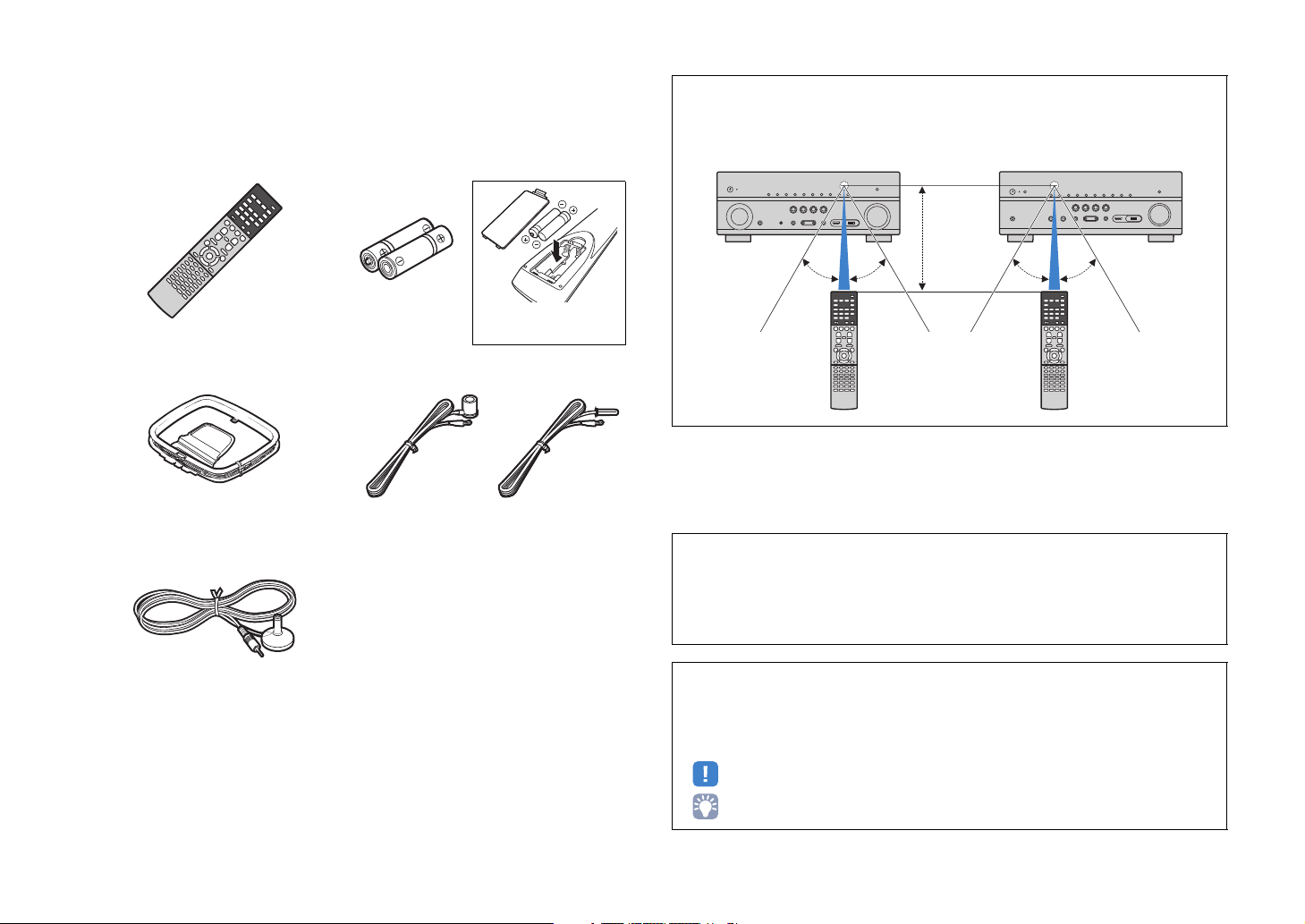
Insert the batteries the right
way round.
30° 30°
Within
6 m (20 ft)
(RX-V779) (RX-V679)
30° 30°
Check that the following accessories are supplied with the product.
Remote control Batteries (AAA, R03, UM-4) (x2)
AM antenna FM antenna
*One of the above is supplied depending on the region of
purchase.
YPAO microphone
Operating range of the remote control
• Point the remote control at the remote control sensor on the unit and remain within the operating range
shown below.
• The illustrations of the main unit and remote control used in this manual are of the RX-V779 (U.S.A.
model), unless otherwise specified.
• In this manual, illustrations of English menu screens are used as examples.
• (RX-V779 [China, Korea, U.K. and Europe models] only)
For information on how to control external devices with the remote control, refer to “Supplement for
Remote Control” on the supplied CD-ROM.
CD-ROM (Owner’s Manual)
Easy Setup Guide
Safety Brochure
En 5
• Some features are not available in certain regions.
• Due to product improvements, specifications and appearance are subject to change without notice.
• This manual explains operations using the supplied remote control.
• This manual describes all the “iPod” and “iPhone” as the “iPod”. “iPod” refers to both “iPod” and
“iPhone” unless otherwise specified.
• indicates precautions for use of the unit and its feature limitations.
• indicates supplementary explanations for better use.
FEATURES
AV receiver (the unit)
Speakers
BD/DVD player
HDMI Control
Audio/Video
TV remote control
Audio
HDMI Control
Audio
Audio/Video
TV
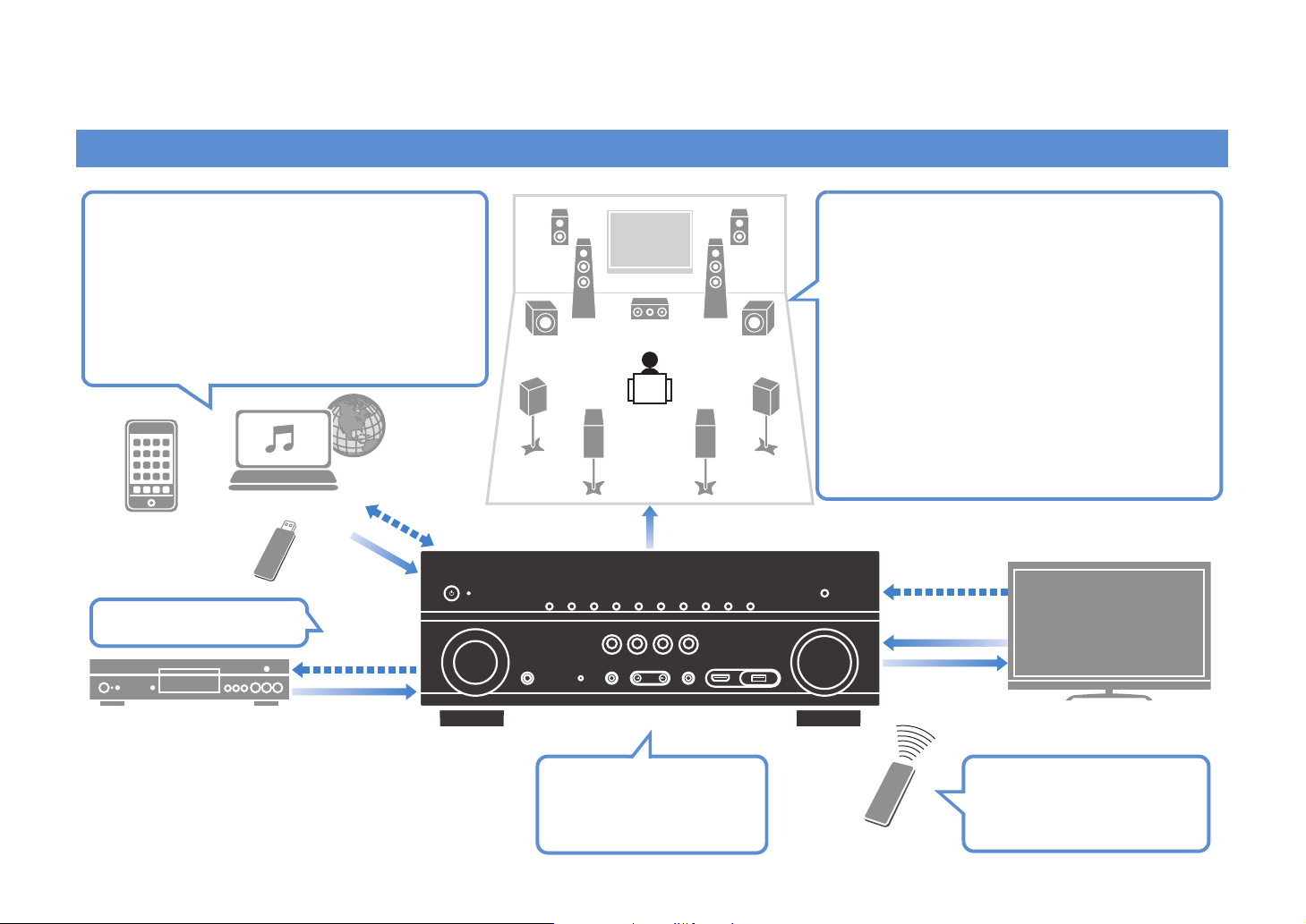
Sequential operation of a TV,
AV receiver, and BD/DVD
player (HDMI Control)
. p.139
Change the input source
and favorite settings with
one touch (SCENE)
. p.54
Supports 2- to 7.1-channel (plus presence)
speaker system. Allows you to enjoy your favorite
acoustic spaces in various styles.
• Automatically optimizing the speaker
settings to suit your room (YPAO)
. p.36
• Reproducing stereo or multichannel
sounds with the sound fields like
actual movie theaters and concert halls
(CINEMA DSP)
. p.56
• Enjoying compressed music with
enhanced sound (Compressed Music
Enhancer)
. p.60
• Playing back music in multiple rooms
(multi-zone)
. p.82
iPod/iPhone/
Bluetooth device
USB device
Audio
Network contents
Wide variety of supported content
•Bluetooth
. p.66
• iPod/iPhone
. p.67
•USB
. p.70
• Media server (PC/NAS)
. p.73
• Internet radio
. p.77
•AirPlay
. p.80
4K Ultra HD signals and
HDCP 2.2 supported
Control
What you can do with the unit
En 6
Full of useful functions!
HDMI Control
TV audio
Video from
external device
Wi-Fi or
Wireless Direct
VSBS
Useful tips
❑ Connecting various devices (p.27)
A number of HDMI jacks and various input/output jacks
on the unit allow you to connect video devices (such as
BD/DVD players), audio devices (such as CD players),
game consoles, camcorders, and other devices.
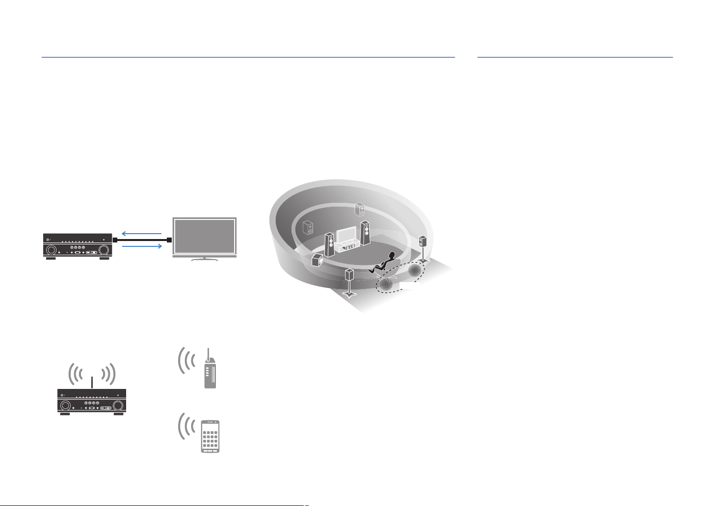
❑ Playing back TV audio in surround sound
with a single HDMI cable connection
(Audio Return Channel: ARC) (p.25)
When using an ARC-compatible TV, you only need one
HDMI cable to enable video output to the TV, audio
input from the TV, and the transmission of HDMI Control
signals.
❑
Various wireless connection methods (
The unit supports the Wi-Fi feature that allows the unit to
connect to your wireless router (access point) without a
network cable connection. In addition, Wireless Direct
enables connecting a mobile device to the unit directly
without router.
p.44
❑ Creating 3-dimensional sound fields (p.56)
Connecting presence speakers allows you to create a
natural 3-dimensional sound field in your own room
(CINEMA DSP 3D). Even when no presence speakers
are connected, the Virtual Presence Speaker (VPS)
function produces 3D surround sound. In addition, the
unit creates Virtual Surround Back Speaker (VSBS)
using the surround speakers to add a sense of depth to
the rear sound field even when no surround back
speakers are connected.
)
❑ Surround playback with 5 speakers placed
in front (p.58)
If you have surround speakers but there is no space to
place them in the rear of your room, you can place them in
the front and enjoy multichannel surround sound with the 5
speakers placed in the front (Virtual CINEMA FRONT).
❑ Low power consumption (p.117)
The ECO mode (power saving function) reduces the
unit’s power consumption.
The combination of video/audio input jacks does not
match an external device...
Use “Audio In” in the “Input” menu to change the
combination of video/audio input jacks so that it matches
p.28
the output jack(s) of your external device (
Video and audio are not synchronized...
Use “Lipsync” in the “Setup” menu to adjust the delay
between video and audio output (p.107).
I want to hear audio from the TV speakers...
Use “Audio Output” in the “Setup” menu to select the
output destination of signals input into the unit (p.111).
Your TV speakers may be selected as an output
destination.
I want to get more bass sounds…
Set “Extra Bass” in the “Option” menu to “On” to enjoy
enhanced bass sounds (p.93).
I want to change the on-screen menu language...
Use “Language” in the “Setup” menu to select a
language from English, Japanese, French, German,
Spanish, Russian, Italian and Chinese (p.35).
I want to update the firmware...
Use “UPDATE” in the “ADVANCED SETUP” menu to
update the unit’s firmware (p.122). If the unit is
connected to the Internet, a message will be displayed
on the TV when a firmware update is available (p.123).
Many other settings are available that let you to
customize the unit. For details, see the following pages.
• Input settings (p.94)
• SCENE settings (p.97)
• Sound program and surround decoder settings (p.99)
• Various function settings (p.102)
• Information view (such as audio signal and video
signal) (p.118)
• System settings (p.120)
).
En 7

Useful applications
■ AV CONTROLLER
“AV CONTROLLER” will turn your smartphone/tablet into
a Wi-Fi enabled remote control for your Yamaha network
products. This application provides you the flexibility to
control the available inputs, volume, mute, power
commands and playback source.
Functions
• Power on/off and volume adjustment
• Input, scene and sound mode selection
• DSP Parameter adjustment
• Playback control (including music selection for some
sources)
• For details, search for “AV CONTROLLER” on the App Store or
Google Play.
■ AV SETUP GUIDE (for tablet)
“AV SETUP GUIDE” is an application that assists you
with cable connections between AV receiver and source
devices as well as AV receiver setup. This application
guides you through the various settings such as
speaker connections, TV and video/audio device
connections and selecting the speaker system.
Functions
• Connection guide (speakers, TV and video/audio
devices)
• Setup guide (YPAO settings and various setup
assistance with illustrations)
• Viewing owner’s manual
• For details, search for “AV SETUP GUIDE” on the App Store or
Google Play.
En 8
Part names and functions
INFO (WPS)ZONE 2
ZONE CONTROL
MEMORY
PRESET
FM AM
TUNING
CONTROL
TV
BD
DVD
NET
RADIO
INPUT
SCENE
MAIN ZONE
PHONES
SILENT
CINEMA
(CONNECT)
STRAIGHT
PURE DIRECT
HDMIIN
5V 1A
VIDEO
VOLUME
AUX
TONE
PROGRAM
YPAO MIC
:9 B2 34561 78 A
C
LF
EDHIJ KG
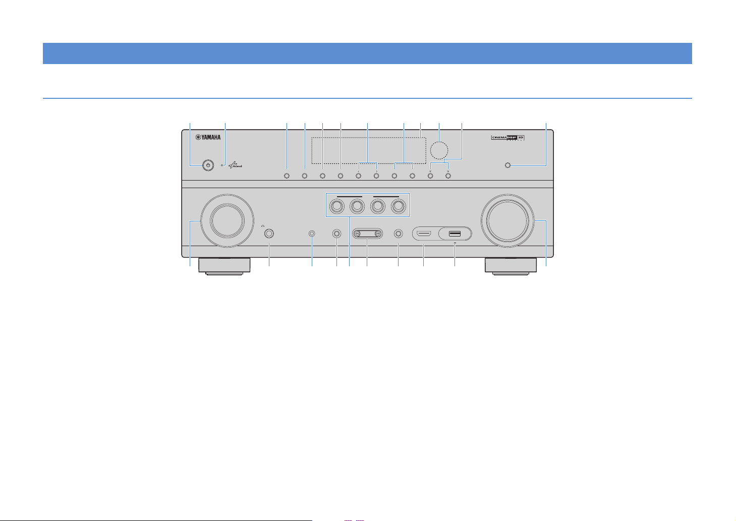
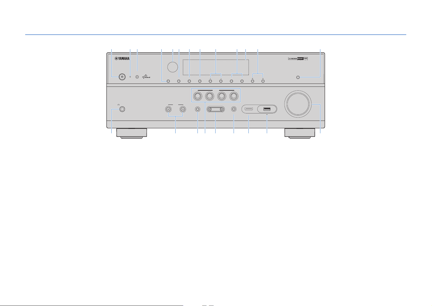
Front panel (RX-V779)
1 MAIN ZONE z key
Turns on/off (standby) the unit.
2 Standby indicator
Lights up when the unit is in standby mode under any of the
following conditions.
• HDMI Control is enabled (p.110)
• Standby Through is enabled (p.111)
• Network Standby is enabled (p.112)
• An iPod is being charged (p.67)
3 ZONE 2 key
Enables/disables the audio output to Zone2 (p.85).
4 ZONE CONTROL key
Changes the zone (main zone or the Zone2) that is controlled
by the keys and knobs on the front panel (p.85).
5 INFO (WPS) key
Selects the information displayed on the front display (p.90).
Enters the wireless network connection setup (WPS push
button configuration) by holding down for 3 seconds (p.47).
6 MEMORY key
Registers FM/AM radio stations as preset stations (p.62).
7 PRESET keys
Select a preset FM/AM radio station (p.62).
8 FM and AM keys
Switch between FM and AM (p.61).
9 Front display
Displays information (p.11).
0 Remote control sensor
Receives remote control signals (p.5).
A TUNING keys
Select the radio frequency (p.61).
B PURE DIRECT key
Enables/disables Pure Direct (p.60).
C INPUT knob
Selects an input source.
D PHONES jack
For connecting headphones.
E YPAO MIC jack
For connecting the supplied YPAO microphone (p.36).
F TONE CONTROL key
Adjusts the high-frequency range and low-frequency range
of output sounds (p.92).
G SCENE keys
Select the registered input source, sound program, and
various settings with one touch. Also, turns on the unit when
it is in standby mode (p.54).
H PROGRAM keys
Select a sound program or a surround decoder (p.55).
I STRAIGHT key
Enables/disables the straight decode mode (p.59).
J VIDEO AUX (HDMI IN) jack
For connecting a device, such as a camcorder and a game
console (p.30).
K USB jack
For connecting a USB storage device (p.70) or an iPod
(p.67).
L VOLUME knob
Adjusts the volume.
En 9
Front panel (RX-V679)
INFO (WPS)ZONE 2
ZONE CONTROL
MEMORY
PRESET
FM AM
TUNING
CONTROL
TV
BD
DVD
NET
RADIO
SCENE
MAIN ZONE
PHONES
SILENT
CINEMA
STRAIGHT
PURE DIRECT
VIDEO
VOLUME
AUX
TONE
PROGRAM
YPAO MIC
INPUT
HDMI IN
5V 1A
(CONNECT)
5A C3 46781 2 9:
D
L
FHIJ KEG
B
1 MAIN ZONE z key
Turns on/off (standby) the unit.
2 Standby indicator
Lights up when the unit is in standby mode under any of the
following conditions.
• HDMI Control is enabled (p.110)
• Standby Through is enabled (p.111)
• Network Standby is enabled (p.112)
• An iPod is being charged (p.67)
3 YPAO MIC jack
For connecting the supplied YPAO microphone (p.36).
4 ZONE 2 key
Enables/disables the audio output to Zone2 (p.85).
5 Remote control sensor
Receives remote control signals (p.5).
6 ZONE CONTROL key
Changes the zone (main zone or the Zone2) that is controlled
by the keys and knobs on the front panel (p.85).
7 INFO (WPS) key
Selects the information displayed on the front display (p.90).
Enters the wireless network connection setup (WPS push
button configuration) by holding down for 3 seconds (p.47).
8 MEMORY key
Registers FM/AM radio stations as preset stations (p.62).
9 PRESET keys
Select a preset FM/AM radio station (p.62).
0 FM and AM keys
Switch between FM and AM (p.61).
A Front display
Displays information (p.11).
B TUNING keys
Select the radio frequency (p.61).
C PURE DIRECT key
Enables/disables Pure Direct (p.60).
D PHONES jack
For connecting headphones.
E INPUT keys
Select an input source.
F TONE CONTROL key
Adjusts the high-frequency range and low-frequency range
of output sounds (p.92).
En 10
G SCENE keys
Select the registered input source, sound program, and
various settings with one touch. Also, turns on the unit when
it is in standby mode (p.54).
H PROGRAM keys
Select a sound program or a surround decoder (p.55).
I STRAIGHT key
Enables/disables the straight decode mode (p.59).
J VIDEO AUX (HDMI IN) jack
For connecting a device, such as a camcorder and a game
console (p.30).
K USB jack
For connecting a USB storage device (p.70) or an iPod
(p.67).
L VOLUME knob
Adjusts the volume.
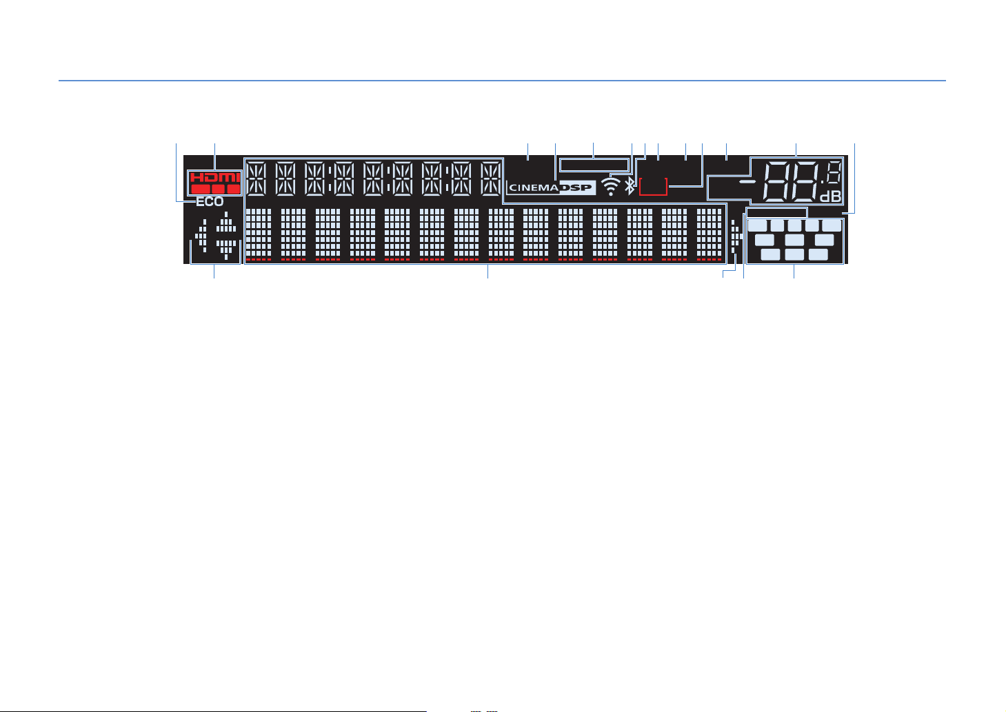
Front display (indicators)
L C R
FPRFPL
SL
SBL SBRSB
SW
SR
VOL.
MUTE
ADAPTIVE DRC VIRTUAL
ENHANCER
TUNEDSTEREO
2
SLEEP
PA RT Y
ZONE
OUT 1
2
2 C34 87 9 A1 :6B5
D DE
F G
1 ECO
Lights up when the unit is in the eco mode (p.117).
2 HDMI
Lights up when HDMI signals are being input or output.
OUT1/OUT2 (RX-V779 only)
Indicates the HDMI OUT jacks currently outputting an HDMI
signal
OUT (RX-V679 only)
Lights up when HDMI signals are being output.
3 ENHANCER
Lights up when Compressed Music Enhancer (p.60) is
working.
4 CINEMA DSP
Lights up when CINEMA DSP or CINEMA DSP 3D (p.56) is
working.
5 STEREO
Lights up when the unit is receiving a stereo FM radio signal.
TUNED
Lights up when the unit is receiving an FM/AM radio station
signal.
7 Bluetooth indicator
Lights up when the unit is connecting to a
(p.66).
8 PA RT Y
Lights up when the unit is in the party mode (p.86).
9 SLEEP
Lights up when the sleep timer is on.
0 ZONE2
Lights up when audio output to Zone2 is enabled (p.85).
A MUTE
Blinks when audio is muted.
B Volume indicator
Indicates the current volume.
C VIRTUAL
Lights up when the Virtual Presence Speaker (VPS) or Virtual
Surround Back Speaker (VSBS) (p.56), or the virtual
surround processing (p.58) is working.
D Cursor indicators
Indicate the remote control cursor keys currently operational.
6 Signal strength indicator
Indicates the strength of the wireless network signal (p.44).
Bluetooth
device
Displays the current status (such as input name and sound
mode name). You can switch the information by pressing
INFO (p.90).
F ADAPTIVE DRC
E Information display
Lights up when Adaptive DRC (p.92) is working.
G Speaker indicators
Indicate speaker terminals from which signals are output.
A Front speaker (L)
S Front speaker (R)
D Center speaker
F Surround speaker (L)
G Surround speaker (R)
H Surround back speaker (L)
J Surround back speaker (R)
K Surround back speaker
B Presence speaker (L)
N Presence speaker (R)
En 11
L Subwoofer
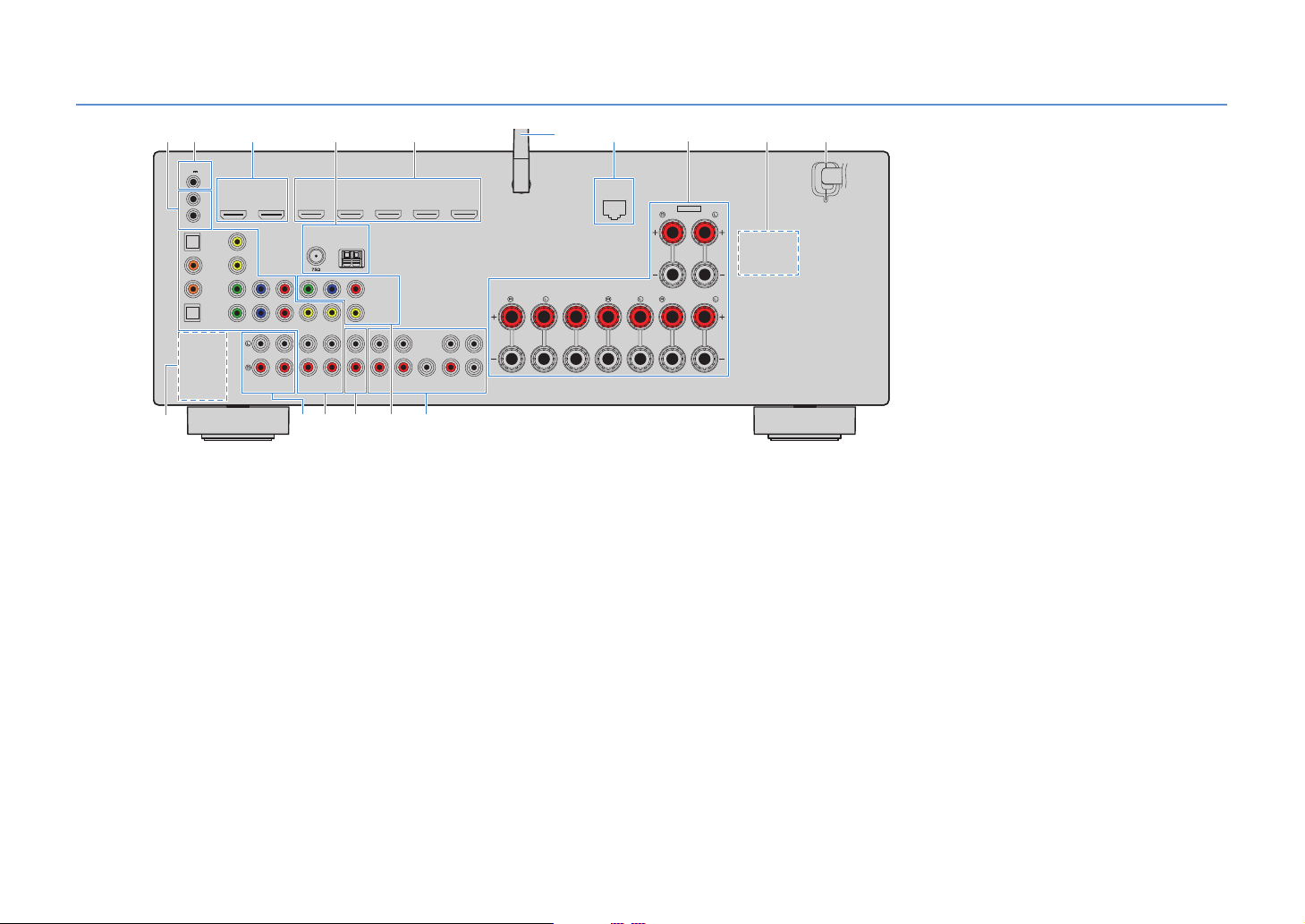
Rear panel (RX-V779)
* The area around the video/audio output jacks is
marked in white on the actual product to
prevent improper connections.
(U.S.A. model)
A
2
TRIGGER OUT
12V
0.1A
IN
OUT
REMOTE
OPTICAL
COAXIAL
OPTICAL
OUT
HDMI
HDCP2.2
12
ARC
VIDEO
(TV)
AV4
AV3
AV2
AV 1
Y
P
PB
COMPONENT VIDEO
AUDIO 1
4
HDMI 1
HDMI 2 HDMI 3
HDCP2.2 HDCP2.2 HDCP2.2
(
)
BD/DVD
ANTENNA
(
)
RADIO
FM
AM
R
Y
PB
R
P
COMPONENT
MONITOR OUT
VIDEO
AUDIO 2
AV 5
B F
C
SINGLE
ZONE 2
SUR. BACK SURROUND
AV 6
ZONE OUT
D
VIDEO
VIDEO
1 REMOTE IN/OUT jacks
For connecting to an infrared signal receiver/emitter that
allows you to operate the unit and other devices from another
room (p.84).
2 TRIGGER OUT jack
For connecting to a device that supports the trigger function
(p.33).
3 HDMI OUT 1–2 jacks
For connecting to HDMI-compatible TVs and outputting
video/audio signals (p.25). When using ARC, TV audio signal
can also be input through the HDMI OUT 1 jack.
4 ANTENNA jacks
For connecting to FM and AM antennas (p.31).
5 HDMI 1–5 jacks
For connecting to HDMI-compatible playback devices and
inputting video/audio signals (p.27).
6 Wireless antenna
For connecting to a network device wirelessly (p.44).
7 NETWORK jack
For connecting to a network with a network cable (p.32).
51 3 7
HDMI 5
HDMI 4
1
2
SUBWOOFER
CENTER FRONT
PRE OUT
6
WIRELESS
CLASS 2 WIRING CABLAGE CLASSE 2
SURROUND CENTER
E
8 SPEAKERS terminals
For connecting to speakers (p.21).
9 VOLTAGE SELECTOR
(General model only)
Selects the switch position according to your local voltage
(p.34).
0 Power cabl e
For connecting to an AC wall outlet (p.34).
A PHONO jacks
(Except for U.S.A. and Canada models)
For connecting to a turntable (p.30).
B AUDIO 1–2 jacks
For connecting to audio playback devices and inputting
audio signals (p.30).
C AV 1–6 jacks
For connecting to video/audio playback devices and
inputting video/audio signals (p.27).
D ZONE2 OUT jacks
For connecting to the external amplifier used in Zone2 and
for outputting audio (p.83).
SPEAKERS
NETWORK
(
NET
FRONT
8
)
EXTRA SP
ZONE2/F.PRESENCE
SURROUND BACK/BI-AMP
9 0
SINGLE
E MONITOR OUT jacks
COMPONENT VIDEO jacks
For connecting to a TV that supports component video and
outputting video signals (p.25).
VIDEO jack
For connecting to a TV that supports composite video and
outputting video signals (p.26).
F PRE OUT jacks
For connecting to a subwoofer with built-in amplifier or to an
external power amplifier (p.33).
En 12
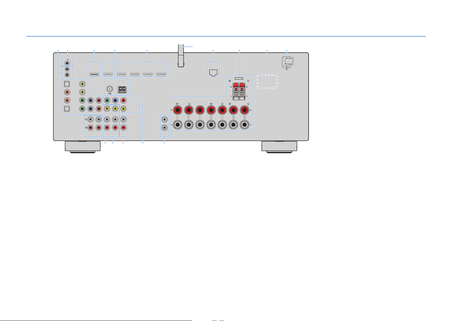
Rear panel (RX-V679)
AUDIO 1
AUDIO 2
OPTICAL
OPTICAL
COAXIAL
VIDEO
AV4
AV3
AV2
AV 1
(TV)
P
B
Y
P
R
COMPONENT
VIDEO
VIDEO
MONITOR OUT
P
B
Y
P
R
HDMI 1
(
BD/DVD
)
HDMI 2 HDMI 3
HDMI 4
HDMI 5
HDCP2.2 HDCP2.2 HDCP2.2
ARC
ANTENNA
FM
AM
SURROUND CENTER
CLASS 2 WIRING CABLAGE CLASSE 2
FRONT
SINGLE
SURROUND BACK/BI-AMP
SPEAKERS
AV 5
VIDEO
AV 6
ZONE OUT
SUBWOOFER
PRE OUT
ZONE 2
NETWORK
TRIGGER OUT
REMOTE
(
NET
)
12V
IN
OUT
0.1A
COMPONENT VIDEO
1
2
HDMI
OUT
(
RADIO
)
WIRELESS
ZONE2/F.PRESENCE
EXTRA SP
HDCP2.2
2
EA
8
C
51 3 7
9 :
B
4 6
D
* The area around the video/audio output jacks is
marked in white on the actual product to prevent
improper connections.
(U.S.A. model)
1 REMOTE IN/OUT jacks
For connecting to an infrared signal receiver/emitter that
allows you to operate the unit and other devices from another
room (p.84).
2 TRIGGER OUT jack
For connecting to a device that supports the trigger function
(p.33).
3 HDMI OUT jack
For connecting to an HDMI-compatible TV and outputting
video/audio signals (p.25). When using ARC, TV audio signal
can also be input through the HDMI OUT jack.
4 ANTENNA jacks
For connecting to FM and AM antennas (p.31).
5 HDMI 1–5 jacks
For connecting to HDMI-compatible playback devices and
inputting video/audio signals (p.27).
6 Wireless antenna
For connecting to a network device wirelessly (p.44).
7 NETWORK jack
For connecting to a network with a network cable (p.32).
8 SPEAKERS terminals
For connecting to speakers (p.21).
9 VOLTAGE SELECTOR
(General model only)
Selects the switch position according to your local voltage
(p.34).
0 Power cabl e
For connecting to an AC wall outlet (p.34).
A AUDIO 1–2 jacks
For connecting to audio playback devices and inputting
audio signals (p.30).
B AV 1–6 jacks
For connecting to video/audio playback devices and
inputting video/audio signals (p.27).
C ZONE2 OUT jacks
For connecting to the external amplifier used in Zone2 and
for outputting audio (p.83).
En 13
D MONITOR OUT jacks
COMPONENT VIDEO jacks
For connecting to a TV that supports component video and
outputting video signals (p.25).
VIDEO jack
For connecting to a TV that supports composite video and
outputting video signals (p.26).
E SUBWOOFER PRE OUT 1–2 jacks
For connecting to a subwoofer with built-in amplifier (p.33).
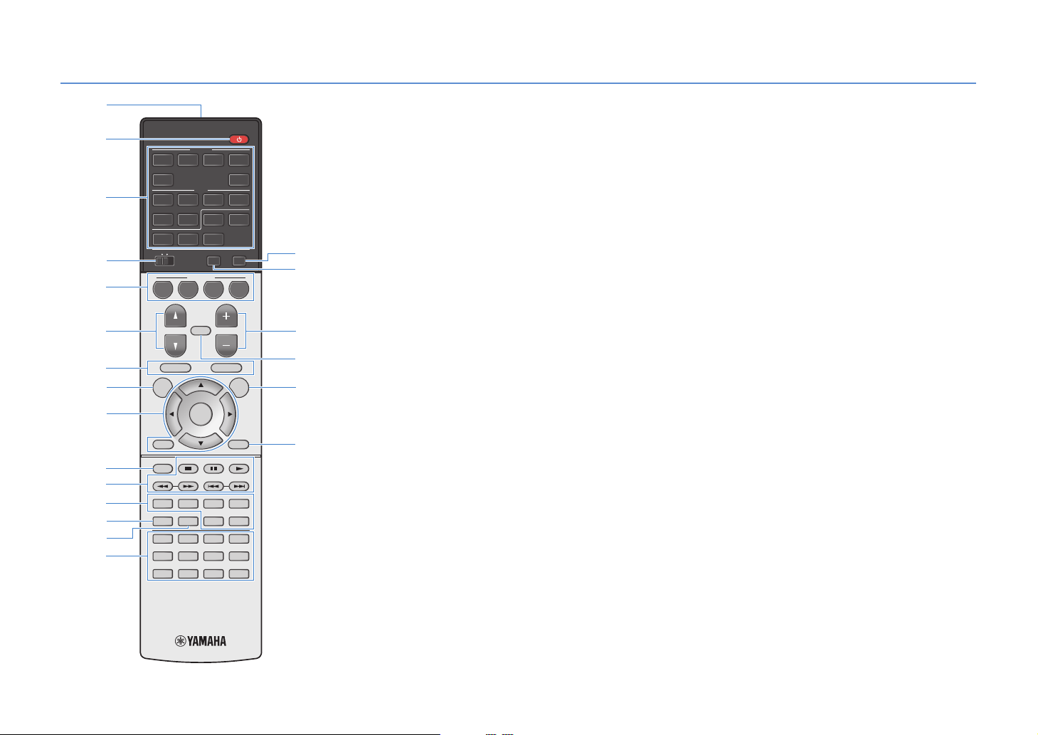
Remote control
G
I
F
J
K
1
3
2
5
4
6
H
7
E
D
8
A
B
:
C
9
(RX-V779 U.S.A. model)
HDMI
123 4
5
AV
12
AUDIO
65
BLUETOOTH
USB
NET
ZONE 2
TOP MENU
TV
SCENE
MUTE
PARTY HDMI OUT
NET
MAIN
BD
DVD
PROGRAM VOLUME
ON
SCREEN
ENTER
MODE
TUNING PRESET
MOVIE
SUR. DECODE
MUSIC
ENHANCER
INFO SLEEP
123 4
5
6 87
90
MEMORY
V-AUX
3 4
TUNER
RADIO
POP-UP/MENU
OPTION
DISPLAYRETURN
BAND
STRAIGHT
PURE DIRECT
ENT
1 Remote control signal transmitter
Transmits infrared signals.
2 z (receiver power) key
Turns on/off (standby) the unit.
3 Input selection keys
Select an input source for playback.
HDMI 1–5 HDMI 1–5 jacks
V-A UX VIDEO AUX jack (on the front panel)
AV 1 – 6 AV 1–6 jacks
AUDIO AUDIO 1–2 jacks (press repeatedly to select
“AUDIO1” or “AUDIO2”)
TUNER FM/AM radio
BLUETOOTH
Bluetooth
connection
(the unit as a
Bluetooth
receiver)
USB USB jack (on the front panel)
NET NETWORK sources (press repeatedly to select
PHONO
a desired network source)
(RX-V779 [except for U.S.A. and Canada models])
PHONO jacks
4 MAIN/ZONE2 switch
Changes the zone (main zone or Zone2) that is controlled by
the remote control (p.85).
5 SCENE keys
Select the registered input source, sound program, and
various settings with one touch. Also, turns on the unit when
it is in standby mode (p.54).
6 PROGRAM keys
Select a sound program (p.55).
7 External device operation keys
Displays menus for the HDMI Control-compatible playback
device (p.139).
8 ON SCREEN key
Displays the on-screen menu on the TV.
9 Menu operation keys
Cursor keys Select a menu or a parameter.
ENTER Confirms a selected item.
RETURN Returns to the previous screen.
0 MODE key
Switches the iPod operation modes (p.69).
A Radio keys
Operate the FM/AM radio when “TUNER” is selected as the
input source (p.61).
BAND Switches between FM and AM radio.
PRESET Select a preset station.
TUNING Select the radio frequency.
External device operation keys
Let you perform playback operations when “USB” or “NET” is
selected as the input source, or control playback of the
HDMI Control-compatible playback device (p.139).
B Sound mode keys
Select a sound mode (p.55).
C INFO key
Selects the information displayed on the front display (p.90).
D SLEEP key
Switches the unit to standby mode automatically after a
specified period of time has elapsed (sleep timer). Press
repeatedly to set the time (120 min, 90 min, 60 min, 30 min, off).
E Numeric keys
Let you enter numerical values, such as radio frequencies.
MEMORY key
Registers FM/AM radio stations as presets (p.62).
En 14
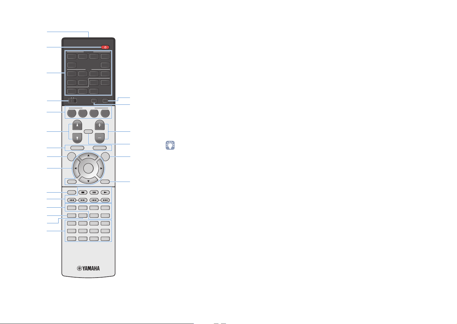
1
(RX-V779 U.S.A. model)
2
3
4
5
6
7
8
9
HDMI
123 4
5
AV
12
AUDIO
65
BLUETOOTH
USB
NET
ZONE 2
TOP MENU
SCENE
TV
MUTE
ENTER
PARTY HDMI OUT
NET
MAIN
BD
DVD
PROGRAM VOLUME
ON
SCREEN
V-AUX
3 4
TUNER
RADIO
POP-UP/MENU
OPTION
F
G
H
I
J
F HDMI OUT key
(RX-V779)
Selects HDMI OUT jacks to be used for video/audio output
(p.53).
(RX-V679)
Enables/disables video/audio output from the HDMI OUT
jack (p.53).
G PA RT Y k e y
Turns on/off the party mode (p.86).
H VOLU ME keys
Adjust the volume.
I MUTE key
Mutes the audio output.
J OPTION key
Displays the option menu (p.91).
K DISPLAY key
Displays status information on the TV (p.90).
• (RX-V779 [China, Korea, U.K. and Europe models] only)
For information on the keys other than those above, refer to
“Supplement for Remote Control” on the supplied CD-ROM.
:
A
B
C
D
E
MODE
TUNING PRESET
MOVIE
MUSIC
INFO SLEEP
123 4
5
90
SUR. DECODE
6 87
ENHANCER
MEMORY
DISPLAYRETURN
BAND
STRAIGHT
PURE DIRECT
ENT
K
En 15

PREPARATIONS
General setup procedure
1 Placing speakers (p.17)
2 Connecting speakers (p.21)
3 Connecting a TV (p.25)
4 Connecting playback devices (p.27)
5 Connecting the FM/AM antennas (p.31)
Connecting a network cable or preparing
6
the wireless antenna (p.32)
7 Connecting other devices (p.33)
8 Connecting the power cable (p.34)
Selecting an on-screen menu language
9
(p.35)
Optimizing the speaker settings
10
automatically (YPAO) (p.36)
Select the speaker layout for the number of speakers that you are using and place them in your room.
Connect the speakers to the unit.
Connect a TV to the unit.
Connect video devices (such as BD/DVD players) and audio devices (such as CD players) to the unit.
Connect the supplied FM/AM antennas to the unit.
Connect the unit to a router (access point) with a network cable, or prepare the wireless antenna for
establishing a wireless network connection.
Connect external devices, such as an external power amplifier (RX-V779 only) and a device compatible
with the trigger function.
After all the connections are complete, plug in the power cable.
Select the desired on-screen menu language (default: English).
Optimize the speaker settings, such as volume balance and acoustic parameters, to suit your room
(YPAO).
Connecting to a network device wirelessly
11
(p.44)
This completes all the preparations. Enjoy playing movies, music, radio and other content with the unit!
Connect the unit to a wireless router (access point) or a mobile device by establishing a wireless
connection.
En 16
1 2 3 4 5 6 7 8 9 10 11
1 Placing speakers
Select the speaker layout for the number of speakers that you are using and place the speakers and subwoofer (with built-in amplifier) in your room. This section describes the
representative speaker layout examples.
Caution
• Under its default settings, the unit is configured for 8-ohm speakers. When connecting 6-ohm speakers, set the unit’s speaker impedance to “6 MIN”. In this case, you can also use 4-ohm speakers as the front speakers.
For details, see “Setting the speaker impedance” (p.20).
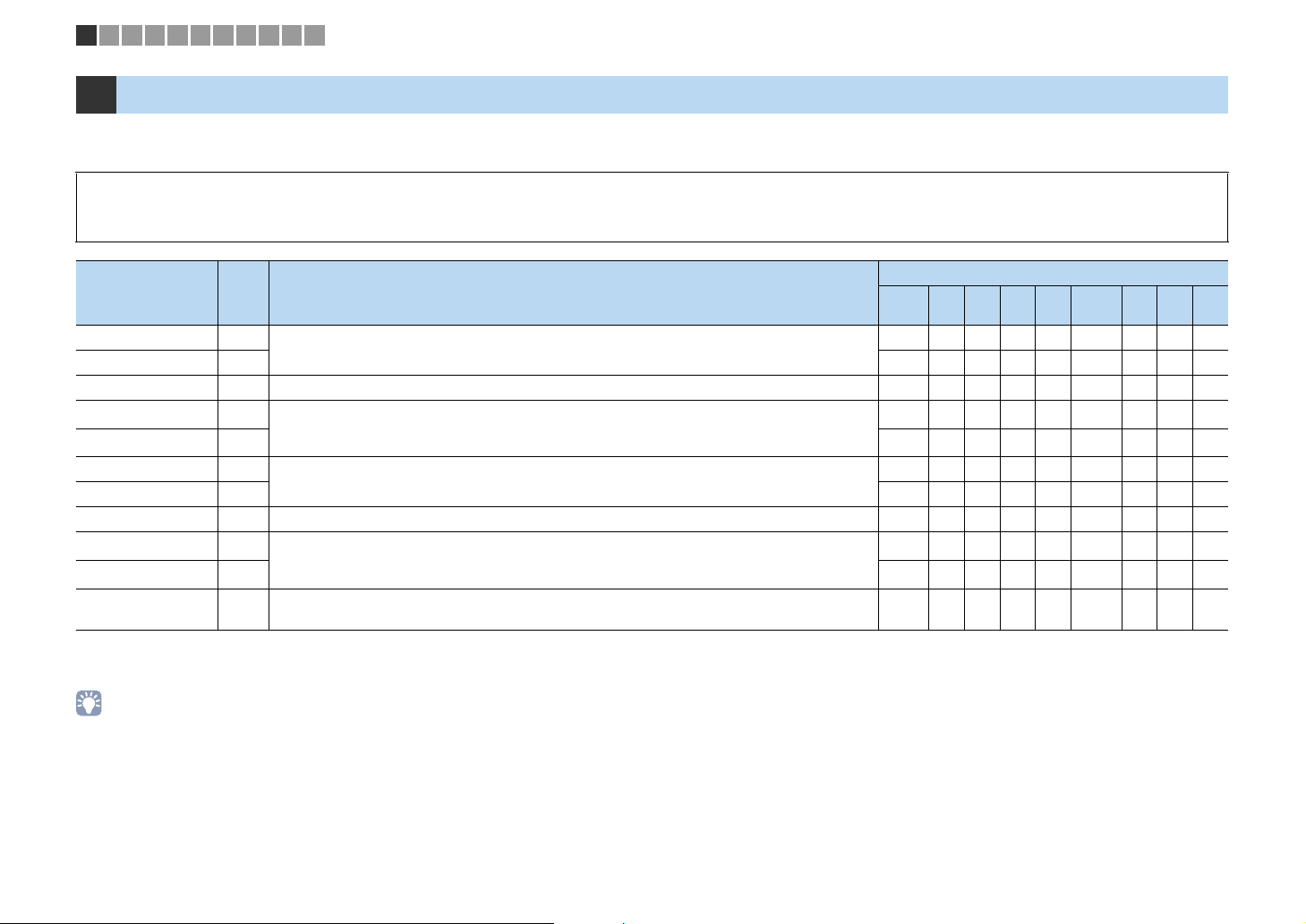
Speaker system (the number of channels)
Speaker type Abbr. Function
Front (L) 1
Front (R) 2 ● ●●●● ● ●●●
Center 3 Produces center channel sounds (such as movie dialogue and vocals). ●●●●●● ●
Surround (L) 4
Surround (R) 5 ●●●●●
Surround back (L) 6
Surround back (R) 7 ●●
Surround back 8 Produces sounds mixed from surround back left/right channel sounds. ●
Presence (L) E
Presence (R) R ●●
Subwoofer 9
Produce front left/right channel sounds (stereo sounds).
Produce surround left/right channel sounds. Surround speakers also produce surround back channel
sounds when no surround back speakers are connected.
Produce surround back left/right channel sounds.
Produce CINEMA DSP effect sounds. In combination with CINEMA DSP 3D (p.56), the presence speakers
create a natural 3-dimensional sound field in your room.
Produces LFE (low-frequency effect) channel sounds and reinforces the bass parts of other channels.
This channel is counted as “0.1”. You can connect 2 subwoofers (with built-in amplifier) to the unit.
7.1+2 7.1 7.1 6.1 5.1
● ●●●● ● ●●●
●●●●●
●●
●●
● ●●●● ● ●●●
Front
5.1
*
*
*
*
4.1 3.1 2.1
1
●
1
●
2
2
If you use five speakers in the front side, use two of them as front surround speakers (*1) or presence speakers (*2). We recommend using them as front surround speakers for
enjoying unprocessed playback (p.59) or presence speakers for enjoying stereoscopic sound fields (p.56).
• For information on the ideal speaker layout, see “Ideal speaker layout” (p.133).
• If you have seven speakers, use two of them as surround back speakers or presence speakers.
To reinforce the rear left/right sounds, use them as surround back speakers.
To create a natural 3-dimensional sound field, use them as presence speakers.
• Two subwoofers connected to the unit output the same sounds.
En 17
45
1
2
39
67
ER
9
45
1
2
39
67
45
1
2
39
8
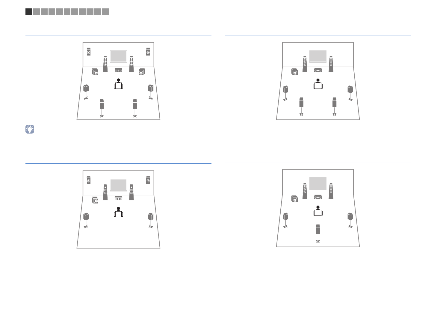
1 2 3 4 5 6 7 8 9 10 11
7.1+2-channel system
• The surround back speakers and presence speakers do not produce sounds simultaneously. The unit
automatically changes the speakers to be used, depending on the selected CINEMA DSP (p.56).
7.1-channel system (using presence speakers)
ER
1
2
39
7.1-channel system (using surround back speakers)
This speaker system creates Virtual Presence Speaker (VPS) using the front, center and
surround speakers to produce a 3-dimensional sound field, and also allows you to
enjoy extended surround sounds using the surround back speakers.
6.1-channel system
45
This speaker system uses the front presence speakers to produce a natural
3-dimensional sound field, and also creates Virtual Surround Back Speaker (VSBS)
using the surround speakers to add a sense of depth to the rear sound field. This
system is suited for enjoying not only 5.1-channel but also for 7.1-channel contents.
This speaker system creates Virtual Presence Speaker (VPS) using the front, center and
surround speakers to produce a 3-dimensional sound field, and also allows you to
enjoy extended surround sounds using the surround back speaker.
En 18
45
12
39
45
12
39
1
2
39
ER
45
12
9
1 2 3 4 5 6 7 8 9 10 11
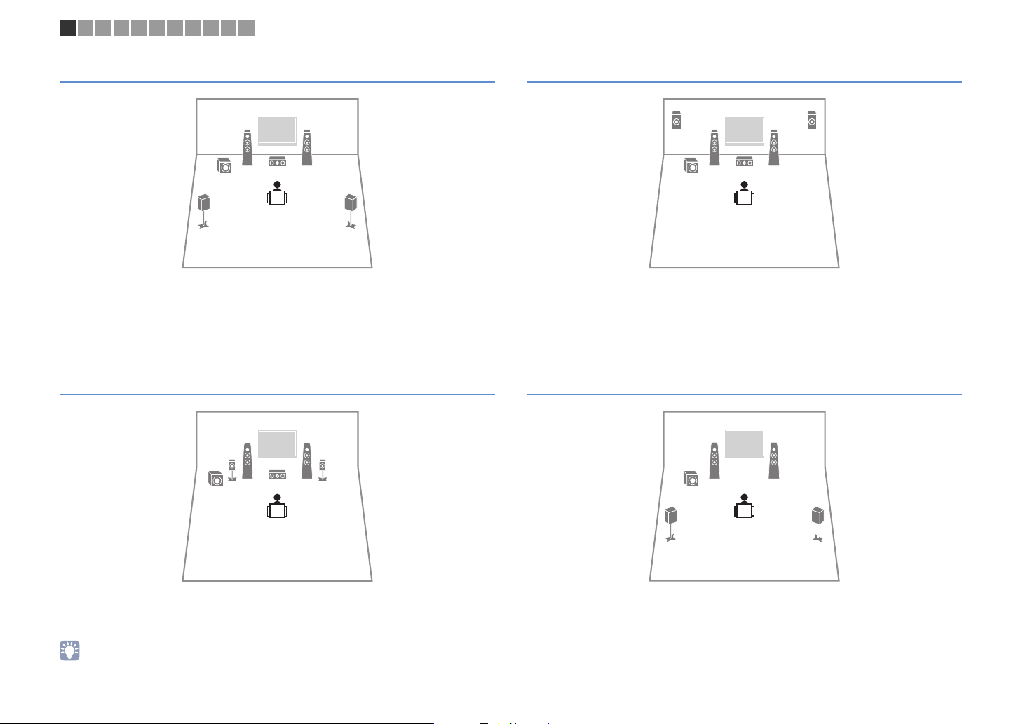
5.1-channel system
This speaker system creates Virtual Presence Speaker (VPS) using the front, center and
surround speakers to produce a 3-dimensional sound field, and also creates Virtual
Surround Back Speaker (VSBS) using the surround speakers to add a sense of depth to
the rear sound field. This system is suited for enjoying not only 5.1-channel but also for
7.1-channel contents.
Front 5.1-channel system (using surround speakers)
Front 5.1-channel system (using presence speakers)
This speaker system uses the front presence speakers to produce a natural
3-dimensional sound field, and creates the virtual surround speakers using the front
speakers to allow you to enjoy multichannel surround sound (Virtual CINEMA DSP).
4.1-channel system
Even when surround speakers are placed in the front side, the unit creates the virtual
surround speakers in the rear side to allow you to enjoy multichannel surround sound (Virtual
CINEMA FRONT) when “Layout (Surround)” (
• You can enjoy surround sound even without the center speaker (front 4.1-channel system).
p.105
) in the “Setup” menu is set to “Front”.
En 19
12
9
MAIN ZONE z
STRAIGHT
SPIMP.8MIN
1 2 3 4 5 6 7 8 9 10 11
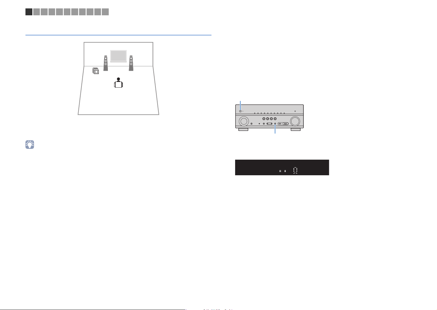
2.1-channel system
Even when no surround speakers are connected, the unit creates the virtual surround
speakers using the front speakers to allow you to enjoy multichannel surround sound
(Virtual CINEMA DSP).
• Add the center speaker to configure a 3.1-channel system.
■ Setting the speaker impedance
Under its default settings, the unit is configured for 8-ohm speakers. When using a
6-ohm speaker for any channel, set the speaker impedance to “6 MIN”. In this case,
you can also use 4-ohm speakers as the front speakers.
Before connecting speakers, connect the power cable to an AC wall
1
outlet.
While holding down STRAIGHT on the front panel, press
2
MAIN ZONE z.
Check that “SP IMP.” is displayed on the front display.
3
Press STRAIGHT to select “6 MIN”.
4
Press MAIN ZONE z to set the unit to standby mode and remove the
5
power cable from the AC wall outlet.
You are now ready to connect the speakers.
En 20
–
+
–
+
SURROUND CENTER
CLASS 2 WIRING CABLAGE CLASSE 2
FRONT
SINGLE
SURROUND BACK/BI-AMP
SPEAKERS
SUBWOOFER
ZONE2/F.PRESENCE
EXTRA SP
1
2
The unit (rear)
SURROUND CENTER
CLASS 2 WIRING CABLAGE CLASSE 2
FRONT
SINGLE
SURROUND BACK/BI-AMP
SPEAKERS
SUBWOOFER
ZONE2/F.PRESENCE
EXTRA SP
1
2
The unit (rear)
1 2 3 4 5 6 7 8 9 10 11
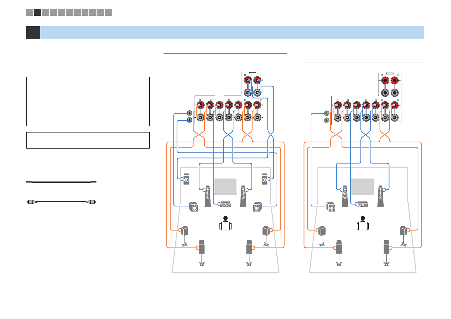
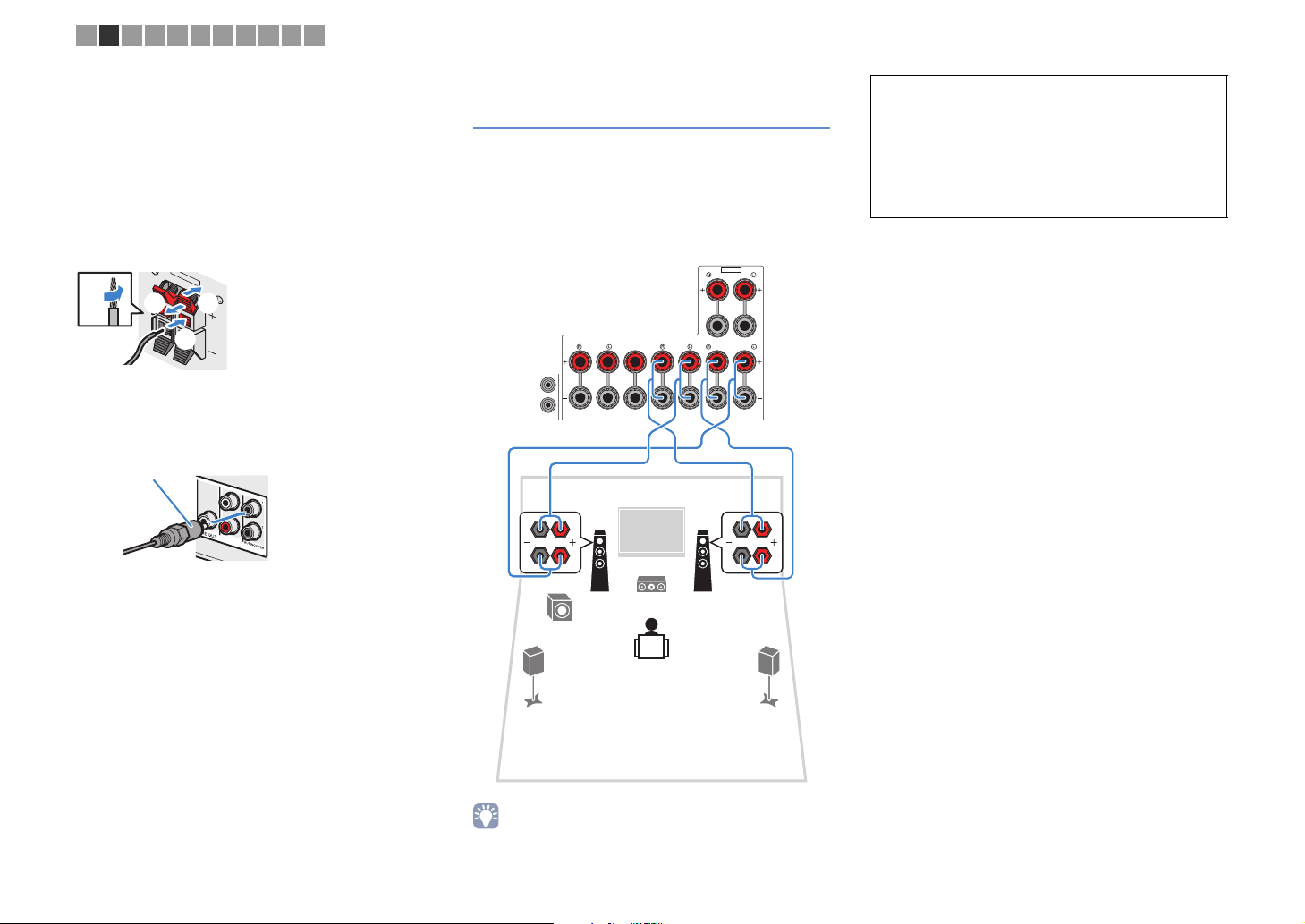
2 Connecting speakers
Connect the speakers placed in your room to the unit.
The following diagrams provide connections for 7.1+2-,
7.1-, and 6.1-channel systems as examples. For other
systems, connect speakers while referring to the
connection diagram for the 6.1-channel system.
Caution
• Remove the unit’s power cable from an AC wall outlet and turn
off the subwoofer before connecting the speakers.
• Ensure that the core wires of the speaker cable do not touch
one another or come into contact with the unit’s metal parts.
Doing so may damage the unit or the speakers. If the speaker
cables short circuit, “Check SP Wires” will appear on the front
display when the unit is turned on.
• The illustrations of the unit (rear) used in this section are of the
RX-V779.
Cables required for connection
(commercially available)
Speaker cables (x the number of speakers)
Audio pin cable (two for connecting two subwoofers)
7.1+2-channel system 7.1-channel system
(using surround back speakers)
ER
1
9
45
3
2
9
1
9
3
45
2
67
En 21
67
SURROUND CENTER
CLASS 2 WIRING CABLAGE CLASSE 2
FRONT
SINGLE
SURROUND BACK/BI-AMP
SPEAKERS
SUBWOOFER
ZONE2/F.PRESENCE
EXTRA SP
1
2
12
3
45
9
ER
The unit (rear)
SURROUND CENTER
CLASS 2 WIRING CABLAGE CLASSE 2
FRONT
SINGLE
SURROUND BACK/BI-AMP
SPEAKERS
SUBWOOFER
ZONE2/F.PRESENCE
EXTRA SP
1
2
12
3
45
9
8
When using only one surround back speaker, connect it
to the SINGLE jack (L side).
The unit (rear)
FRONT
aa
b
d
c
+ (red)
- (black)
FRONT
Banana plug
1 2 3 4 5 6 7 8 9 10 11
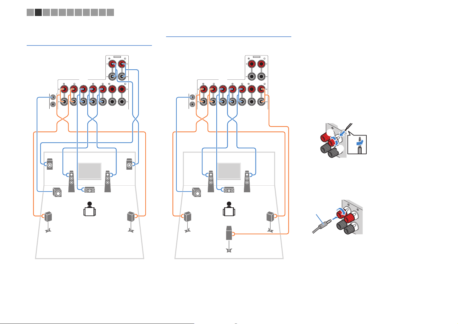
7.1-channel system
(using presence speakers)
6.1-channel system
■ Connecting speaker cables
Speaker cables have two wires. One is for connecting
the negative (-) terminal of the unit and the speaker, and
the other is for the positive (+) terminal. If the wires are
colored to prevent confusion, connect the black wire to
the negative and the other wire to the positive terminal.
a Remove approximately 10 mm (3/8”) of insulation from
the ends of the speaker cable and twist the bare wires of
the cable firmly together.
b Loosen the speaker terminal.
c Insert the bare wires of the cable into the gap on the side
(upper right or bottom left) of the terminal.
d Tighten the terminal.
Using a banana plug
(U.S.A., Canada, China, Australia and General models only)
a Tighten the speaker terminal.
b Insert a banana plug into the end of the terminal.
a
b
En 22
Z
EX
+ (red)
- (black)
CENTER
FRONT
Audio pin cable
12
3
45
9
SURROUND CENTER
CLASS 2 WIRING CABLAGE CLASSE 2
FRONT
SINGLE
SURROUND BACK/BI-AMP
SPEAKERS
SUBWOOFER
ZONE2/F.PRESENCE
EXTRA SP
1
2
The unit (rear)
1 2 3 4 5 6 7 8 9 10 11
Push-type speaker terminals
(RX-V679 only)
a Remove approximately 10 mm (3/8”) of insulation from
the ends of the speaker cable, and twist the bare wires of
the cable firmly together.
b Press down the tab.
c Insert the bare wires of the cable into the hole in the
terminal.
d Release the tab.
ONE 2/F.PRESENCE
TRA SP
aa
d
b
c
■ Connecting the subwoofer
Use an audio pin cable to connect the subwoofer.
Connecting front speakers that support bi-amp connections
When using front speakers that support bi-amp
connections, connect them to the FRONT jacks and
SURROUND BACK/BI-AMP jacks.
To enable the bi-amp function, set “Power Amp Assign”
(p.104) in the “Setup” menu to “5ch BI-AMP” after
connecting the power cable to an AC wall outlet.
Caution
• Before making bi-amp connections, remove any brackets or
cables that connect a woofer with a tweeter. Refer to the
instruction manual of the speakers for details. If you are not
making bi-amp connections, make sure that the brackets or
cables are connected before connecting the speaker cables.
• Surround back speakers cannot be used during bi-amp
connections.
• The FRONT jacks and SURROUND BACK/BI-AMP jacks output the
same signals.
En 23
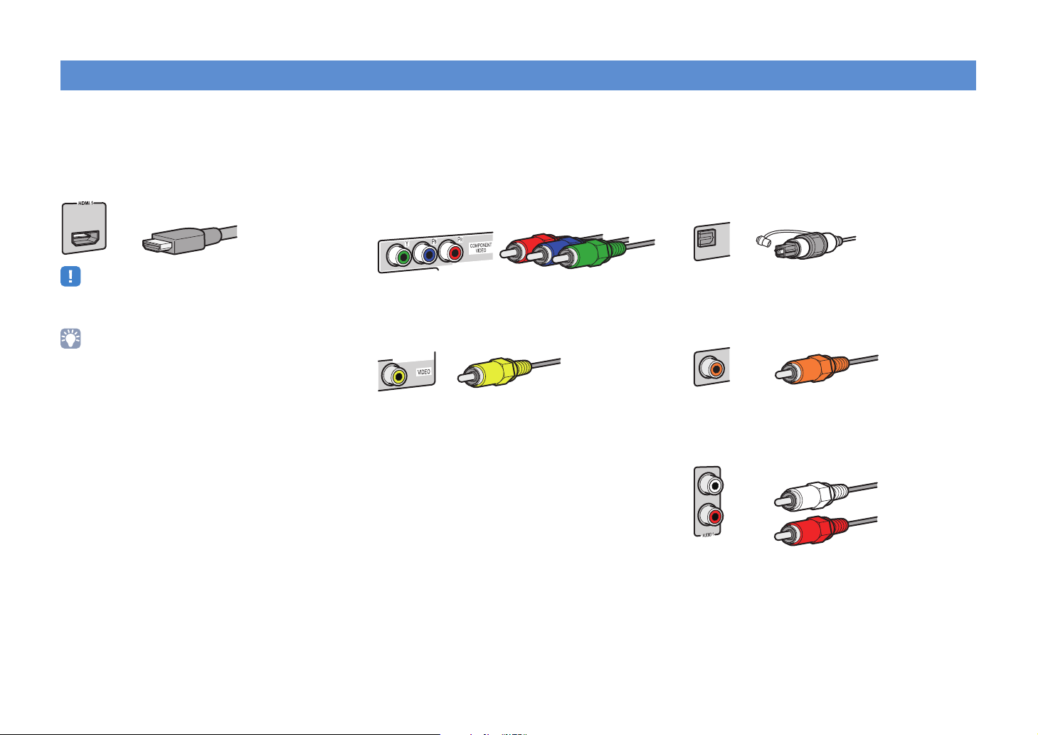
Input/output jacks and cables
HDCP2.2
(BD/DVD)
HDMI cable
Component video cable
Video pin cable
OPTICAL
Digital optical cable
Digital coaxial cable
Stereo pin cable
■ Video/audio jacks
❑ HDMI jacks
Transmit digital video and digital sound through a single
jack. Use an HDMI cable.
• Use a 19-pin HDMI cable with the HDMI logo. We recommend using
a cable less than 5.0 m (16.4 ft) long to prevent signal quality
degradation.
• The unit’s HDMI jacks support the HDMI Control, Audio Return
Channel (ARC), and 3D and 4K Ultra HD video transmission
features.
• Use high speed HDMI cables to enjoy 3D or 4K Ultra HD videos.
■ Video jacks
❑ COMPONENT VIDEO jacks
Transmit video signals separated into three
components: luminance (Y), chrominance blue (P
and chrominance red (P
R). Use a component video
cable with three plugs.
MONITOR OUT
❑ VIDEO jacks
Transmit analog video signals. Use a video pin cable.
MONITOR OUT
B),
■ Audio jacks
❑ OPTICAL jacks
Transmit digital audio signals. Use a digital optical
cable. Remove the tip protector (if available) before
using the cable.
❑ COAXIAL jacks
Transmit digital audio signals. Use a digital coaxial
cable.
COAXIAL
❑ AUDIO jacks
Transmit analog stereo audio signals. Use a stereo pin
cable (RCA cable).
En 24
M
V
O
H
H
A
G
The unit (rear)
HDMI OUT jack
AV 4 (OPTICAL) jack
Audio output
(digital optical)
TV
HDMI input
AUDIO 1
AUDIO 2
OPTICAL
OPTICAL
COAXIAL
VIDEO
AV4
AV3
AV2
AV 1
(TV)
P
B
Y
P
R
COMPONENT
VIDEO
VIDEO
MONITOR OUT
P
B
Y
P
R
HDMI 1
(
BD/DVD
)
HDMI 2 HDMI 3
H
HDCP2.2
HDCP2.2
HDCP2.2 HDCP2.2
12
ARC
ANTENNA
FM
AM
AV 5
VIDEO
AV 6
ZONE OUT
SUR. BACK SURROUNDPRC
SINGLE
ZONE 2
TRIGGER OUT
REMOTE
12V
IN
OUT
0.1A
COMPONENT VIDEO
HDMI
OUT
(
RADIO
)
PR
PB
Y
COMPONENT
VIDEO
P
R
P
B
Y
P
R
P
B
Y
OPTICAL
OPTICAL
AV4
(TV)
O
O
COMPONENT
VIDEO
MONITOR OUT
P
B
Y
P
R
The unit (rear)
MONITOR OUT
(COMPONENT VIDEO)
jacks
Video input
(component video)
AV 4 (OPTICAL) jack
Audio output
(digital optical)
TV
1 2 3 4 5 6 7 8 9 10 11
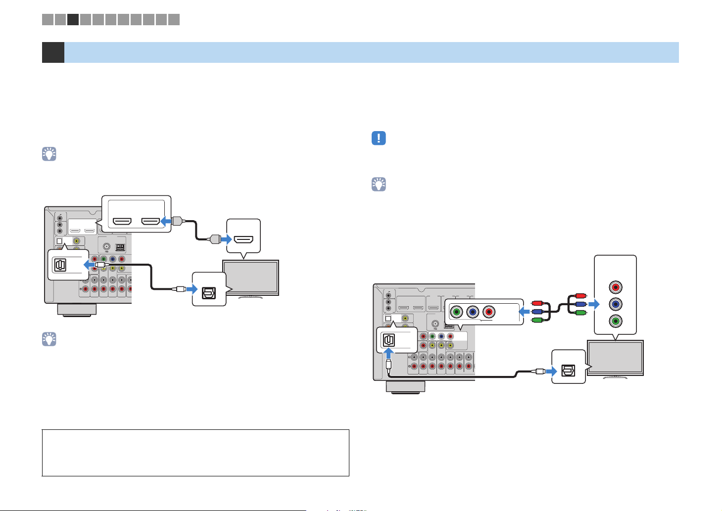
3 Connecting a TV
Connect a TV to the unit so that video input to the unit can be output to the TV.
You can also enjoy playback of TV audio on the unit.
To maximize the performance of the unit, we recommend connecting a TV with an HDMI
cable.
■ HDMI connection
Connect the TV to the unit with an HDMI cable and a digital optical cable.
• (RX-V779 only)
You can connect another TV or a projector by using the HDMI OUT 2 jack (p.26).
OUT
HDMI
HDCP2.2
TRIGGER OUT
12V
0.1A
OUT
HDMI
HDCP2.2
IN
OUT
REMOTE
OPTICAL
VIDEO
(TV)
AV4
COAXIAL
AV3
Y
P
B
OPTICAL
AV2
OPTICAL
(TV)
AV4
AV 1
COMPONENT VIDEO
AUDIO 1
• You do not make a digital optical cable connection between the TV and the unit in the following cases:
– If your TV supports Audio Return Channel (ARC)
– If you will receive TV broadcasts only from the set-top box
• If you connect a TV that suppor ts HDMI Control to the unit with an HDMI cable, you can control the unit’s
power and volume with the TV’s remote control.
To use HDMI Control and ARC, you need to configure the HDMI settings on the unit. For
details on the settings, see “Information on HDMI” (p.139).
About Audio Return Channel (ARC)
• ARC allows audio signals to travel both ways. If you connect a TV that supports ARC to the unit with a
• When using ARC, connect a TV with an HDMI cable that supports ARC.
single HDMI cable, you can output video/audio to the TV or input TV audio to the unit.
21
HDMI 1
HDMI 2
HDCP2.2
12
HDCP2.2
(
)
BD/DVD
ARC
ANTENNA
(
)
RADIO
FM
AM
R
P
Y
P
B
P
R
CO
MONIT
O
VIDEO
SIN
ZONE 2
AUDIO 2
SUR. B
AV 5
AV 6
ZONE OUT
ARC
HDMI
O
OPTICAL
HDMI
HDMI
En 25
■ Component/composite video connection
When connecting any video device with a component video cable, connect the TV to
the MONITOR OUT (COMPONENT VIDEO) jacks.
When connecting any video device with a video pin cable, connect the TV to the
MONITOR OUT (VIDEO) jack.
• If you connect your TV to the unit with a cable other than HDMI, video input to the unit via HDMI cannot be
output to the TV.
• Operations with TV screen are available only when your TV is connected to the unit via HDMI.
• If you will receive TV broadcasts only from the set-top box, you do not need to make an audio cable
connection between the TV and the unit.
❑ COMPONENT VIDEO connection (with a component video cable)
H
R
C
The unit (rear)
MONITOR OUT
(VIDEO) jack
Video input
(composite video)
AV 4 (OPTICAL) jack
Audio output
(digital optical)
TV
M
V
O
H
H
A
G
The unit (rear)
HDMI OUT 2 jack
HDMI input
Projector
TV (already connected)
TV
1 2 3 4 5 6 7 8 9 10 11
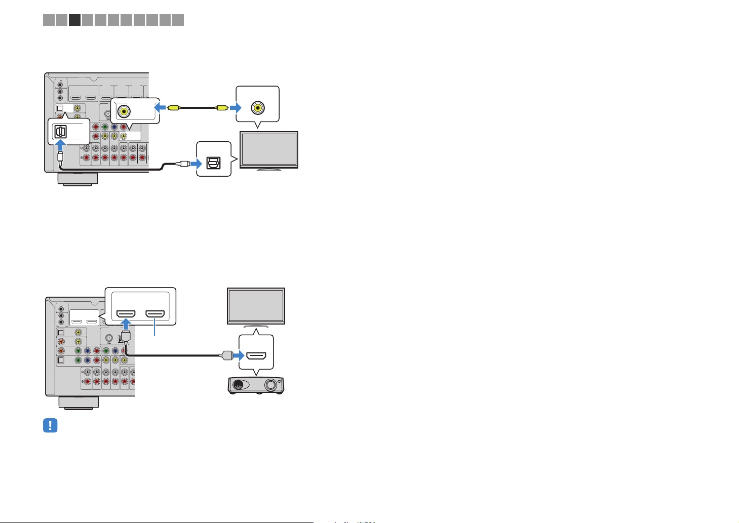
❑ VIDEO (composite video) connection (with a video pin cable)
TRIGGER OUT
12V
0.1A
IN
OUT
REMOTE
OPTICAL
(TV)
AV4
COAXIAL
AV3
Y
OPTICAL
AV2
OPTICAL
AV4
AV 1
O
OUT
HDMI
HDCP2.2
VIDEO
P
B
(TV)
COMPONENT VIDEO
AUDIO 1
HDMI 1
HDMI 2 HDMI 3
HDCP2.2
12
HDCP2.2 HDCP2.2
(
)
BD/DVD
ARC
R
P
AUDIO 2
MONITOR OUT
ANTENNA
(
)
RADIO
FM
AM
VIDEO
Y
P
B
P
R
COMPONENT
VIDEO
MONITOR OUT
VIDEO
VIDEO
SINGLE
ZONE 2
SUR. BACK SURROUND
AV 5
AV 6
ZONE OUT
V
OPTICAL
P
O
VIDEO
V
■ Connecting another TV or a projector
(RX-V779 only)
The unit has two HDMI output jacks. If you connect another TV or a projector to the unit
with an HDMI cable, you can switch the TV (or projector) to be used for watching
videos with the remote control (p.53).
OUT
HDMI
TRIGGER OUT
12V
REMOTE
0.1A
OUT
HDMI
HDCP2.2
IN
12
(
BD/DVD
ARC
OUT
OPTICAL
VIDEO
(TV)
AV4
COAXIAL
AV3
R
P
Y
P
B
AV2
OPTICAL
AV 1
COMPONENT VIDEO
HDCP2.2
21
HDMI 1
HDMI 2
HDCP2.2
HDCP2.2
)
ANTENNA
(
)
RADIO
FM
HDMI
AM
Y
P
B
P
R
CO
MONIT
VIDEO
SIN
ARC
HDMI
HDMI
ZONE 2
AUDIO 2
AUDIO 1
SUR. B
AV 5
AV 6
ZONE OUT
• HDMI Control is not available on the HDMI OUT 2 jack.
En 26
AUDIO 2
P
R
COMPONENT
VIDEO
VIDEO
MONITOR OUT
P
B
Y
P
R
HDMI 1
(
BD/DVD
)
HDMI 2 HDMI 3
HDMI 4
HDMI 5
HDCP2.2 HDCP2.2 HDCP2.2
ARC
ANTENNA
FM
AM
SURROUND CENTER
CLASS 2 WIRING CABLAGE
SPEAKERS
AV 5
VIDEO
AV 6
ZONE OUT
SUBWOOFER
SUR. BACK SURROUND
PRE OUT
CENTER FRONT
SINGLE
ZONE 2
1
2
(
RADIO
)
WIRELESS
HDMI
HDMI 1
(
BD/DVD
)
HDMI 2 HDMI 3
HDMI 4
HDMI 5
HDCP2.2 HDCP2.2 HDCP2.2
HDMI
HDMI
The unit (rear)
HDMI output
Video device
HDMI 1–5 jacks
M
V
O
H
H
A
G
The unit
(rear)
AV 1–2
(COMPONENT VIDEO)
jacks
Video output
(component video)
Video device
Audio output
(digital optical or digital coaxial)
AV 1 (OPTICAL) jack or
AV 2 (COAXIAL) jack
1 2 3 4 5 6 7 8 9 10 11
4 Connecting playback devices
The unit is equipped with a variety of input jacks including HDMI input jacks to allow
you to connect different types of playback devices. For information on how to connect
an iPod or a USB storage device, see the following pages.
– Connecting an iPod (p.67)
– Connecting a USB storage device (p.70)
Connecting video devices (such as BD/DVD players)
Connect video devices such as BD/DVD players, set-top boxes (STBs) and game
consoles to the unit. Depending on the video/audio output jacks available on your video
device, choose one of the following connections. We recommend using an HDMI
connection if the video device has an HDMI output jack.
• If the combination of video/audio input jacks available on the unit does not match your video device, change
its combination according to the output jacks of your device (p.28).
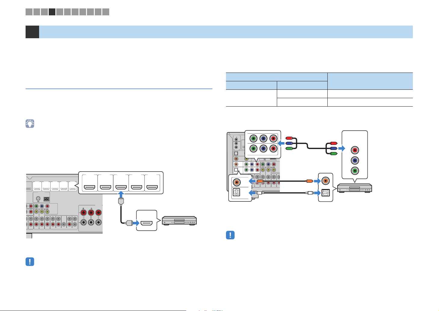
■ HDMI connection
Connect a video device to the unit with an HDMI cable.
■ Component video connection
Connect a video device to the unit with a component video cable and an audio cable
(digital optical or digital coaxial). Choose a set of input jacks (on the unit) depending on
the audio output jacks available on your video device.
Output jacks on video device
Video Audio
Component video
Y
P
(TV)
Y
AV2
AV 1
OUT
HDMI
HDCP2.2
12
VIDEO
P
B
COMPONENT VIDEO
AUDIO 1
B
HDMI 1
HDCP2.2
(
BD/DVD
ARC
COMPONENT VIDEO
R
P
VIDEO
C
AUDIO 2
AV 5
O
TRIGGER OUT
12V
REMOTE
0.1A
IN
OUT
OPTICAL
COAXIAL
OPTICAL
AV4
AV3
AV2
AV 1
OPTICAL
P
R
HDMI 2
HDCP2.2
)
ANTENNA
(
)
RADIO
FM
Y
P
B
AV 6
Digital optical AV 1 (COMPONENT VIDEO + OPTICAL)
Digital coaxial AV 2 (COMPONENT VIDEO + COAXIAL)
R
P
P
B
Y
AM
P
R
CO
MONIT
SIN
ZONE 2
ZONE OUT
SUR. B
C
COAXIAL
O
OPTICAL
If you select the input source by pressing AV 1–2, the video/audio played back on the
video device will be output from the unit.
Input jacks on the unit
COMPONENT
VIDEO
R
P
P
R
P
B
Y
P
B
Y
If you select the input source by pressing HDMI 1–5, the video/audio played back on
the video device will be output from the unit.
• To watch videos input to the HDMI 1–5 jacks, you need to connect your TV to the HDMI OUT jack of the
unit (p.25).
• If your video device supports HDCP 2.2, connect the device to the HDMI 1–3 jacks.
En 27
• The component video signals (other than 480i/576i signals) input to AV 1–2 jacks of the unit can be output
from the MONITOR OUT (COMPONENT VIDEO) jacks only. To watch those videos, you need to connect
your TV to the MONITOR OUT (COMPONENT VIDEO) jacks of the unit (p.25). For details, refer to “Video
signal flow” (p.138).
C
A
Z
The unit (rear)
AV 3–6 (VIDEO)
jack
Video output
(composite video)
Video device
Audio output
(either digital optical,
digital coaxial, or analog stereo)
Any of AV 3 (COAXIAL) jack,
AV 4 (OPTICAL) jack,
AV 5–6 (AUDIO) jacks
O
AV 2 (COMPONENT VIDEO)
jacks
Video output
(component video)
AV 5 (AUDIO) jacks
Video device
Audio output
(analog stereo)
The unit (rear)
1 2 3 4 5 6 7 8 9 10 11
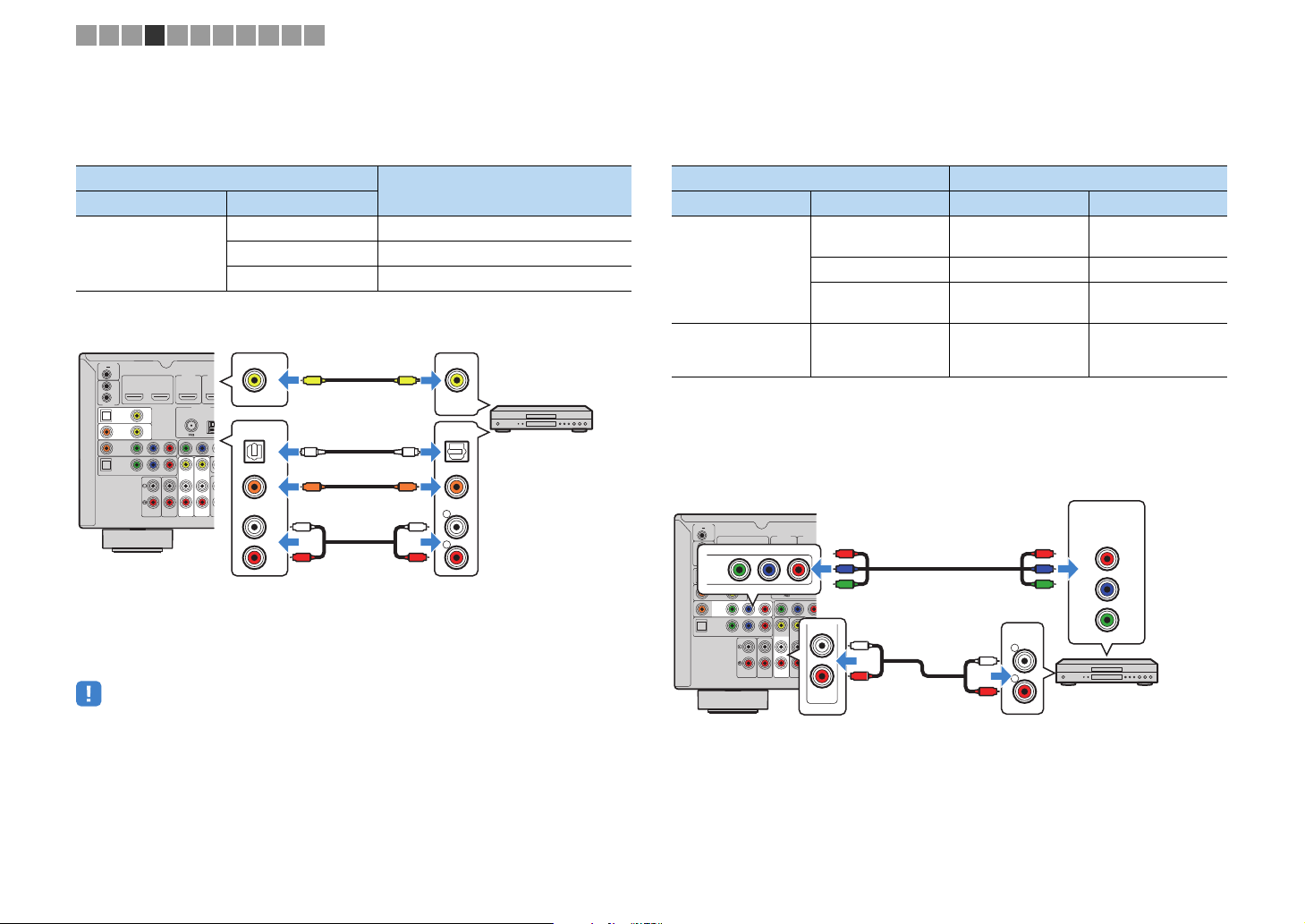
■ Composite video connection
Connect a video device to the unit with a video pin cable and an audio cable (digital
coaxial, digital optical, or stereo pin cable). Choose a set of input jacks (on the unit)
depending on the audio output jacks available on your video device.
Output jacks on video device
Video Audio
Digital coaxial AV 3 (VIDEO + COAXIAL)
Composite video
Digital optical AV 4 (VIDEO + OPTICAL)
Analog stereo AV 5–6 (VIDEO + AUDIO)
TRIGGER OUT
12V
0.1A
IN
OUT
REMOTE
OPTICAL
(TV)
AV4
COAXIAL
AV3
Y
AV2
OPTICAL
AV 1
If you select the input source by pressing AV 3–6, the video/audio played back on the
HDMI 1
OUT
HDMI
HDCP2.2
HDCP2.2
12
(
BD/DVD
ARC
ANTENNA
VIDEO
FM
R
P
Y
P
B
VIDEO
COMPONENT VIDEO
AUDIO 2
AUDIO 1
AV 5
video device will be output from the unit.
• To watch videos input to the AV 3–6 (VIDEO) jacks, you need to connect your TV to the HDMI OUT jack
(p.25) or to the MONITOR OUT (VIDEO) jack (p.26) of the unit. For details, refer to “Video signal flow”
(p.138).
VIDEO
HD
HD
)
(
)
RADIO
P
B
AV 6
V
OPTICAL
OO
COAXIAL
CC
L
R
Input jacks on the unit
VIDEO
V
OPTICAL
COAXIAL
L
L
R
R
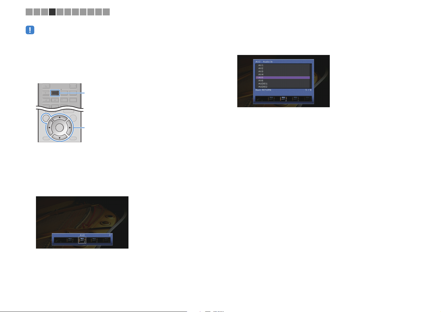
■ Changing the combination of video/audio input jacks
If the combination of video/audio input jacks available on the unit does not match your
video device, change its combination according to the output jacks of your device. You
can connect a video device that has the following video/audio output jacks.
Output jacks on video device Input jacks on the unit
Video Au dio Video Audio
Digital optical HDMI 1–5
HDMI
Digital coaxial HDMI 1–5 AV 2–3 (COAXIAL)
Analog stereo HDMI 1–5
Component video Analog stereo
AV 1–2
(COMPONENT
VIDEO)
❑ Necessary setting
For example, if you have connected a video device to AV 2 (COMPONENT VIDEO) and
AV 5 (AUDIO) jacks of the unit, change the combination setting as follows.
TRIGGER OUT
12V
0.1A
IN
OUT
Y
REMOTE
OPTICAL
(TV)
AV2
AV4
COAXIAL
AV3
Y
AV2
OPTICAL
AV 1
OUT
HDMI
HDCP2.2
12
VIDEO
P
B
COMPONENT VIDEO
AUDIO 1
HDMI 1
HDMI 2
HDCP2.2
HDCP2.2
(
)
BD/DVD
ARC
R
P
P
B
ANTENNA
(
RADIO
FM
R
P
Y
VIDEO
AUDIO 2
AV 5
R
P
P
B
)
AM
Y
P
B
L
ZONE
AV 6
ZONE
R
AV 5
L
R
AUDIO
L
R
R
P
P
B
Y
AV 1 ( OPT ICA L )
AV 4 ( OPT ICA L )
AV 5–6 (AUDIO)
AUDIO 1–2
AV 5–6 (AUDIO)
AUDIO 1–2
COMPONENT
VIDEO
PR
PB
Y
En 28
DISPLAYRETURN
ENTER
ON
SCREEN
OPTION
TOP MENU
POP-UP/MENU
Y
TOP MENU
NET
BLUETOOTH
USB
AV
5
65
V-AUX
12
AUDIO
TUNER
34
V-AUX
AUDIO
TUNER
4
ON SCREEN
ENTER
AV 2
Cursor keys
1 2 3 4 5 6 7 8 9 10 11
• The following operation is available only when your TV is connected to the unit via HDMI.
After connecting external devices (such as a TV and playback
1
devices) and power cable of the unit, turn on the unit.
Press AV 2 to select “AV 2” (video input jack to be used) as the input
2
source.
Press ON SCREEN.
3
Use the cursor keys to select “Input” and press ENTER.
4
Use the cursor keys (e/r) to select “AV2” (video input jack to be
5
used) and press the cursor key (q).
Use the cursor keys to select “Audio In” and press ENTER.
6
Use the cursor keys to select “AV5” (audio input jack to be used).
7
Press ON SCREEN.
8
This completes the necessary settings.
If you select “AV 2” as the input source by pressing AV 2, the video/audio played back
on the video device will be output from the unit.
En 29
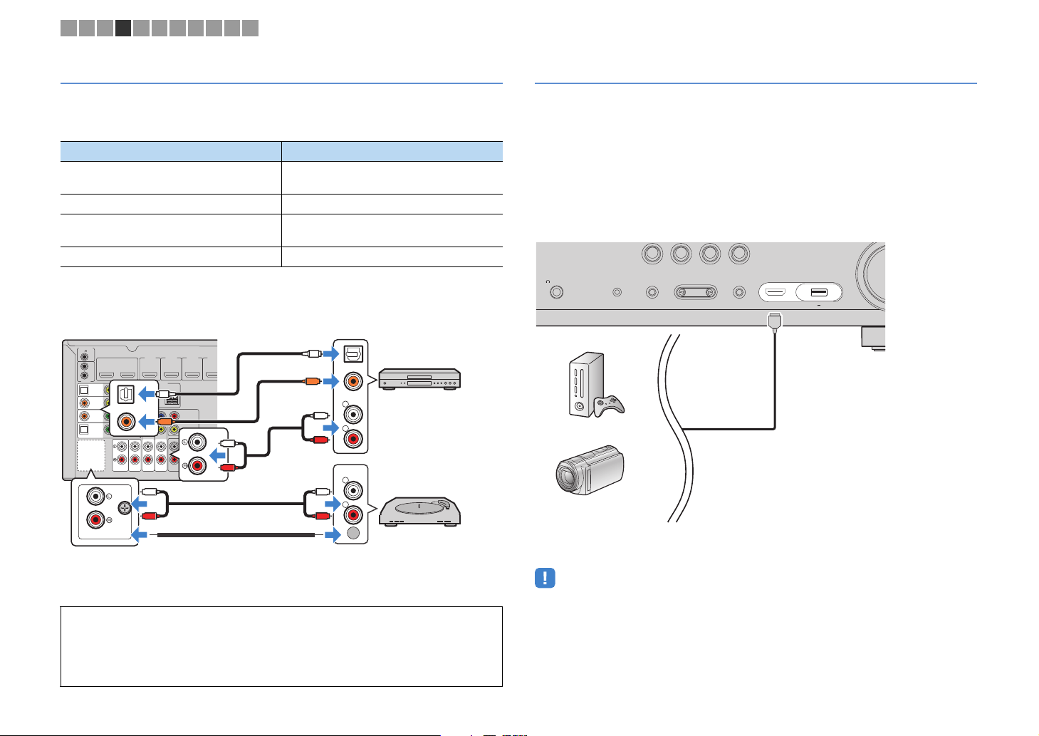
AUDIO 1
AUDIO 2
OPTICAL
OPTICAL
COAXIAL
VIDEO
AV4
AV3
AV2
AV 1
(TV)
P
B
Y
P
R
COMPONENT
VIDEO
VIDEO
MONITOR OUT
P
B
Y
P
R
HDMI 1
(
BD/DVD
)
HDMI 2 HDMI 3
HDMI 4
HDCP2.2
HDCP2.2
HDCP2.2 HDCP2.2
12
ARC
ANTENNA
FM
AM
AV 5
VIDEO
AV 6
ZONE OUT
SUR. BACK SURROUND
PRE OU
CENTER
SINGLE
ZONE 2
TRIGGER OUT
REMOTE
12V
IN
OUT
0.1A
COMPONENT VIDEO
HDMI
OUT
(
RADIO
)
R
L
COAXIAL
OPTICAL
R
L
PHONO
GND
PHONO
GND
OPTICAL
COAXIAL
C
L
R
L
R
O
O
L
R
L
R
C
Audio output
(either digital optical,
digital coaxial, or analog stereo)
AV 1–6 jacks
AUDIO 1–2 jacks
The unit
(rear)
Audio device
PHONO jacks*
Audio output (PHONO)
Turntable
Ground lead
HDMI
Game console
Camcorder
The unit (front)
1 2 3 4 5 6 7 8 9 10 11
Connecting audio devices (such as CD players)
Connect audio devices such as CD players, MD players, and a turntable to the unit.
Depending on the audio output jacks available on your audio device, choose one of the
following connections.
Audio output jacks on audio device Audio output jacks on the unit
Digital optical
Digital coaxial AV 2–3 (COAXIAL)
Analog stereo
Turntable (PHONO) PHONO*
* RX-V779 only (except for U.S.A. and Canada models)
AV 1 (OP T ICA L)
AV 4 (OP T ICA L)
AV 5–6 (AUDIO)
AUDIO 1–2
Connecting to the jacks on the front panel
Use the VIDEO AUX jack to temporarily connect a playback device to the unit.
Use the USB jack to connect an iPod or a USB storage device. For details, see
“Connecting an iPod” (p.67) or “Connecting a USB storage device” (p.70).
Before making a connection, stop playback on the device and turn down the volume on
the unit.
❑ HDMI connection
Connect an HDMI-compatible device (such as game consoles and camcorders) to the
unit with an HDMI cable.
BD
TV
DVD
PHONES
SILENT
CINEMA
YPAO MIC
CONTROL
TONE
PROGRAM
RADIO
NET
AUX
VIDEO
STRAIGHT
(CONNECT)
HDMIIN
5V 1A
If you select the input source by pressing AV 1–6, AUDIO or PHONO*, the audio played
back on the audio device will be output from the unit.
When connecting a turntable
(RX-V779 only [except for U.S.A. and Canada models])
• The PHONO jack of the unit is compatible with an MM cartridge. To connect a turntable with a
low-output MC cartridge, use a boosting transformer.
• Connecting the turntable to the GND terminal of the unit may reduce noise in the signal.
En 30
If you select “V-AUX” as the input source by pressing V-AUX, the video/audio played
back on the device will be output from the unit.
• To watch videos input to the VIDEO AUX (HDMI IN) jack, you need to connect your TV to the HDMI OUT
jack of the unit (p.25).
• You need to prepare an HDMI cable that match the output jacks on your device.
 Loading...