

Page 1

RX-797
Stereo Receiver
Récepteur stéréo
C
OWNER’S MANUAL
MODE D’EMPLOI
Page 2
IMPORTANT SAFETY INSTRUCTIONS
IMPORTANT SAFETY INSTRUCTIONS
CAUTION
RISK OF ELECTRIC SHOCK
DO NOT OPEN
CAUTION: TO REDUCE THE RISK OF
ELECTRIC SHOCK, DO NOT REMOVE
COVER (OR BACK). NO USER-SERVICEABLE
PARTS INSIDE. REFER SERVICING TO
QUALIFIED SERVICE PERSONNEL.
• Explanation of Graphical Symbols
The lightning flash with arrowhead symbol, within an
equilateral triangle, is intended to alert you to the
presence of uninsulated “dangerous voltage” within
the product’s enclosure that may be of sufficient
magnitude to constitute a risk of electric shock to
persons.
The exclamation point within an equilateral triangle
is intended to alert you to the presence of important
operating and maintenance (servicing) instructions in
the literature accompanying the appliance.
Note to CATV system installer:
This reminder is provided to call the CATV system
installer’s attention to Article 820-40 of the NEC that
provides guidelines for proper grounding and, in
particular, specifies that the cable ground shall be
connected to the grounding system of the building, as
close to the point of cable entry as practical.
IMPORTANT
Please record the serial number of this unit in the space
below.
MODEL:
Serial No.:
The serial number is located on the rear of the unit.
Retain this Owner’s Manual in a safe place for future
reference.
1 Read these instructions.
2 Keep these instructions.
3 Heed all warnings.
4 Follow all instructions.
5 Do not use this apparatus near water.
6 Clean only with dry cloth.
7 Do not block any ventilation openings. Install in accordance
with the manufacturer’s instructions.
8 Do not install near any heat sources such as radiators, heat
registers, stoves, or other apparatus (including amplifiers)
that produce heat.
9 Do not defeat the safety purpose of the polarized or
grounding-type plug. A polarized plug has two blades with
one wider than the other. A grounding type plug has two
blades and a third grounding prong. The wide blade or the
third prong are provided for your safety. If the provided plug
does not fit into your outlet, consult an electrician for
replacement of the obsolete outlet.
10 Protect the power cord from being walked on or pinched
particularly at plugs, convenience receptacles, and the point
where they exit from the apparatus.
11 Only use attachments/accessories specified by the
manufacturer.
12 Use only with the cart, stand, tripod,
bracket, or table specified by the
manufacturer, or sold with the apparatus.
When a cart is used, use caution when
moving the cart/apparatus combination to
avoid injury from tip-over.
13 Unplug this apparatus during lightning storms or when
unused for long periods of time.
14 Refer all servicing to qualified service personnel. Servicing
is required when the apparatus has been damaged in any
way, such as power-supply cord or plug is damaged, liquid
has been spilled or objects have fallen into the apparatus, the
apparatus has been exposed to rain or moisture, does not
operate normally, or has been dropped.
We Want You Listening For A Lifetime
YAMAHA and the Electronic Industries Association’s Consumer Electronics Group want you to get the most out of your
equipment by playing it at a safe level. One that lets the sound come through loud and clear without annoying blaring or
distortion – and, most importantly, without affecting your sensitive hearing. Since hearing damage from loud sounds is
often undetectable until it is too late, YAMAHA and the Electronic Industries Association’s Consumer Electronics Group
recommend you to avoid prolonged exposure from excessive volume levels.
i
Page 3

FCC INFORMATION (for US customers)
1 IMPORTANT NOTICE: DO NOT MODIFY THIS
UNIT!
This product, when installed as indicated in the
instructions contained in this manual, meets FCC
requirements. Modifications not expressly approved by
Yamaha may void your authority, granted by the FCC, to
use the product.
2 IMPORTANT: When connecting this product to
accessories and/or another product use only high quality
shielded cables. Cable/s supplied with this product MUST
be used. Follow all installation instructions. Failure to
follow instructions could void your FCC authorization to
use this product in the USA.
3 NOTE: This product has been tested and found to comply
with the requirements listed in FCC Regulations, Part 15
for Class “B” digital devices. Compliance with these
requirements provides a reasonable level of assurance that
your use of this product in a residential environment will
not result in harmful interference with other electronic
devices.
This equipment generates/uses radio frequencies and, if
not installed and used according to the instructions found
in the users manual, may cause interference harmful to the
operation of other electronic devices.
IMPORTANT SAFETY INSTRUCTIONS
Compliance with FCC regulations does not guarantee that
interference will not occur in all installations. If this
product is found to be the source of interference, which
can be determined by turning the unit “OFF” and “ON”,
please try to eliminate the problem by using one of the
following measures:
Relocate either this product or the device that is being
affected by the interference.
Utilize power outlets that are on different branch (circuit
breaker or fuse) circuits or install AC line filter/s.
In the case of radio or TV interference, relocate/reorient
the antenna. If the antenna lead-in is 300 ohm ribbon lead,
change the lead-in to coaxial type cable.
If these corrective measures do not produce satisfactory
results, please contact the local retailer authorized to
distribute this type of product. If you can not locate the
appropriate retailer, please contact Yamaha Electronics
Corp., U.S.A. 6660 Orangethorpe Ave, Buena Park, CA
90620.
The above statements apply ONLY to those products
distributed by Yamaha Corporation of America or its
subsidiaries.
ii
Page 4

CAUTION: READ THIS BEFORE OPERATING YOUR UNIT.
CAUTION: READ THIS BEFORE OPERATING YOUR UNIT.
1 To assure the finest performance, please read this manual
carefully. Keep it in a safe place for future reference.
2 Install this sound system in a well ventilated, cool, dry, clean
place – away from direct sunlight, heat sources, vibration,
dust, moisture, and/or cold. Allow ventilation space of at least
30 cm on the top, 20 cm on the left and right, and 20 cm on
the back of this unit.
3 Locate this unit away from other electrical appliances, motors,
or transformers to avoid humming sounds.
4 Do not expose this unit to sudden temperature changes from
cold to hot, and do not locate this unit in an environment with
high humidity (i.e. a room with a humidifier) to prevent
condensation inside this unit, which may cause an electrical
shock, fire, damage to this unit, and/or personal injury.
5 Avoid installing this unit where foreign objects may fall onto
this unit and/or this unit may be exposed to liquid dripping or
splashing. On the top of this unit, do not place:
– Other components, as they may cause damage and/or
discoloration on the surface of this unit.
– Burning objects (i.e. candles), as they may cause fire,
damage to this unit, and/or personal injury.
– Containers with liquid in them, as they may fall and liquid
may cause electrical shock to the user and/or damage to
this unit.
6 Do not cover this unit with a newspaper, tablecloth, curtain,
etc. in order not to obstruct heat radiation. If the temperature
inside this unit rises, it may cause fire, damage to this unit,
and/or personal injury.
7 Do not plug in this unit to a wall outlet until all connections
are complete.
8 Do not operate this unit upside-down. It may overheat,
possibly causing damage.
9 Do not use force on switches, knobs and/or cords.
10 When disconnecting the power cable from the wall outlet,
grasp the plug; do not pull the cable.
11 Do not clean this unit with chemical solvents; this might
damage the finish. Use a clean, dry cloth.
12 Only voltage specified on this unit must be used. Using this
unit with a higher voltage than specified is dangerous and may
cause fire, damage to this unit, and/or personal injury.
YAMAHA will not be held responsible for any damage
resulting from use of this unit with a voltage other than
specified.
13 To prevent damage by lightning, keep the power cord and
outdoor antennas disconnected from a wall outlet or the unit
during a lightning storm.
14 Do not attempt to modify or fix this unit. Contact qualified
YAMAHA service personnel when any service is needed. The
cabinet should never be opened for any reasons.
15 When not planning to use this unit for long periods of time
(i.e. vacation), disconnect the AC power plug from the wall
outlet.
16 Install this unit near the AC outlet and where the AC power
plug can be reached easily.
17 Be sure to read the “TROUBLESHOOTING” section on
common operating errors before concluding that this unit is
faulty.
18 Before moving this unit, press MASTER ON/OFF to release it
outward to the OFF position, and disconnect the AC power
plug from the wall outlet.
19 VOLTAGE SELECTOR (Asia and General models only)
The VOLTAGE SELECTOR on the rear panel of this unit
must be set for your local main voltage BEFORE plugging
into the AC main supply. Voltages are:
General model .............AC 110/120/220/230–240 V, 50/60 Hz
Asia model ................................ AC 220/230–240 V, 50/60 Hz
\
WARNING
TO REDUCE THE RISK OF FIRE OR ELECTRIC
SHOCK, DO NOT EXPOSE THIS UNIT TO RAIN
OR MOISTURE.
As long as this unit is connected to the AC wall outlet,
it is not disconnected from the AC power source even
if you turn off this unit by MASTER ON/OFF, or
MAIN ZONE ON/OFF and ZONE 2 ON/OFF. In this
state, this unit is designed to consume a very small
quantity of power.
FOR CANADIAN CUSTOMERS
To prevent electric shock, match wide blade of plug to
wide slot and fully insert.
This Class B digital apparatus complies with Canadian
ICES-003.
iii
Page 5

CONTENTS
INTRODUCTION
FEATURES............................................................. 2
SUPPLIED ACCESSORIES ................................. 2
CONTROLS AND FUNCTIONS ......................... 3
Front panel ................................................................. 3
Front panel display .................................................... 5
Rear panel .................................................................. 6
Remote control........................................................... 7
Zone 2 remote control................................................ 9
Installing batteries in the remote controls................ 11
Using the remote controls ........................................ 11
PREPARATION
CONNECTIONS .................................................. 12
Connecting speakers ................................................ 12
Connecting audio and video components................ 13
Connecting the AM and FM antennas ..................... 14
Connecting the power supply cord .......................... 16
Turning on and off this unit ..................................... 17
BASIC OPERATION
PLAYING AND RECORDING .......................... 18
Playing a source....................................................... 18
Adjusting the tonal quality....................................... 20
Recording a source .................................................. 21
Using the sleep timer ............................................... 22
Muting the sound output .......................................... 23
FM/AM TUNING ................................................. 24
Automatic tuning ..................................................... 24
Manual tuning.......................................................... 25
Automatic preset tuning........................................... 26
Manual preset tuning ............................................... 28
Selecting preset stations........................................... 29
Exchanging preset stations ...................................... 29
XM SATELLITE RADIO TUNING .................. 30
What is XM Satellite Radio? ................................... 30
XM Satellite Radio connections .............................. 30
XM Satellite Radio functions .................................. 31
Activating XM Satellite Radio ................................ 33
Basic XM Satellite Radio operations....................... 34
XM Satellite Radio search modes............................ 35
Setting XM Satellite Radio preset channels ............ 37
ADVANCED OPERATION
ADVANCED SETUP ............................................39
Changing the ADVANCED SETUP menu
parameters ........................................................... 39
Switching the remote control ID ............................. 40
ZONE 2 ..................................................................41
Connecting the Zone 2 components ........................ 41
Controlling Zone 2................................................... 42
REMOTE CONTROL FEATURES ...................43
Control area ............................................................. 43
Controlling other components ................................. 44
Setting remote control codes ................................... 45
ADDITIONAL INFORMATION
TROUBLESHOOTING .......................................46
SPECIFICATIONS...............................................49
PREPARATIONINTRODUCTION
OPERATION
BASIC
OPERATION
ADVANCED
INFORMATION
ADDITIONAL
1
English
Page 6
FEATURES
FEATURES
Built-in 2-channel power amplifier
◆ Minimum RMS output power
100 W + 100 W (8 Ω), 0.019% THD, 20 Hz to 20 kHz
◆ Highly dynamic power, low impedance drive
capability
Sophisticated AM/FM tuner
◆ 40-station random access preset tuning
◆ Automatic preset tuning
◆ Preset station exchanging capability
◆ Radio Data System tuning capability
(Europe model only)
Other features
◆ PURE DIRECT button used to reproduce the purest
source sound
◆ CD DIRECT AMP button used to reproduce the purest
CD sound
◆ REC OUT selector independent of input source
selection
◆ Continuously variable loudness control
◆ Sleep timer
◆ Remote control capability
◆ Zone 2 remote control supplied
◆ Zone 2 custom installation facility
XM Satellite Radio
(U.S.A. model only)
◆ XM Satellite Radio tuning capability using the XM
Connect-and-Play
™
digital antenna accessory (sold
separately)
• y indicates a tip for your operation.
• Some operations can be performed by using either the buttons on the front panel of this unit or those on the remote controls. In case
the button names differ between this unit and the remote controls, the names of the buttons on the remote controls are given in
parentheses.
• In case the buttons on the remote control and the Zone 2 remote control have certain functions in common, the illustrations of the
buttons on the remote control are used for explanation throughout the manual.
• This manual is printed prior to production. Design and specifications are subject to change in part as a result of improvements, etc. In
case of differences between the manual and the product, the product has priority.
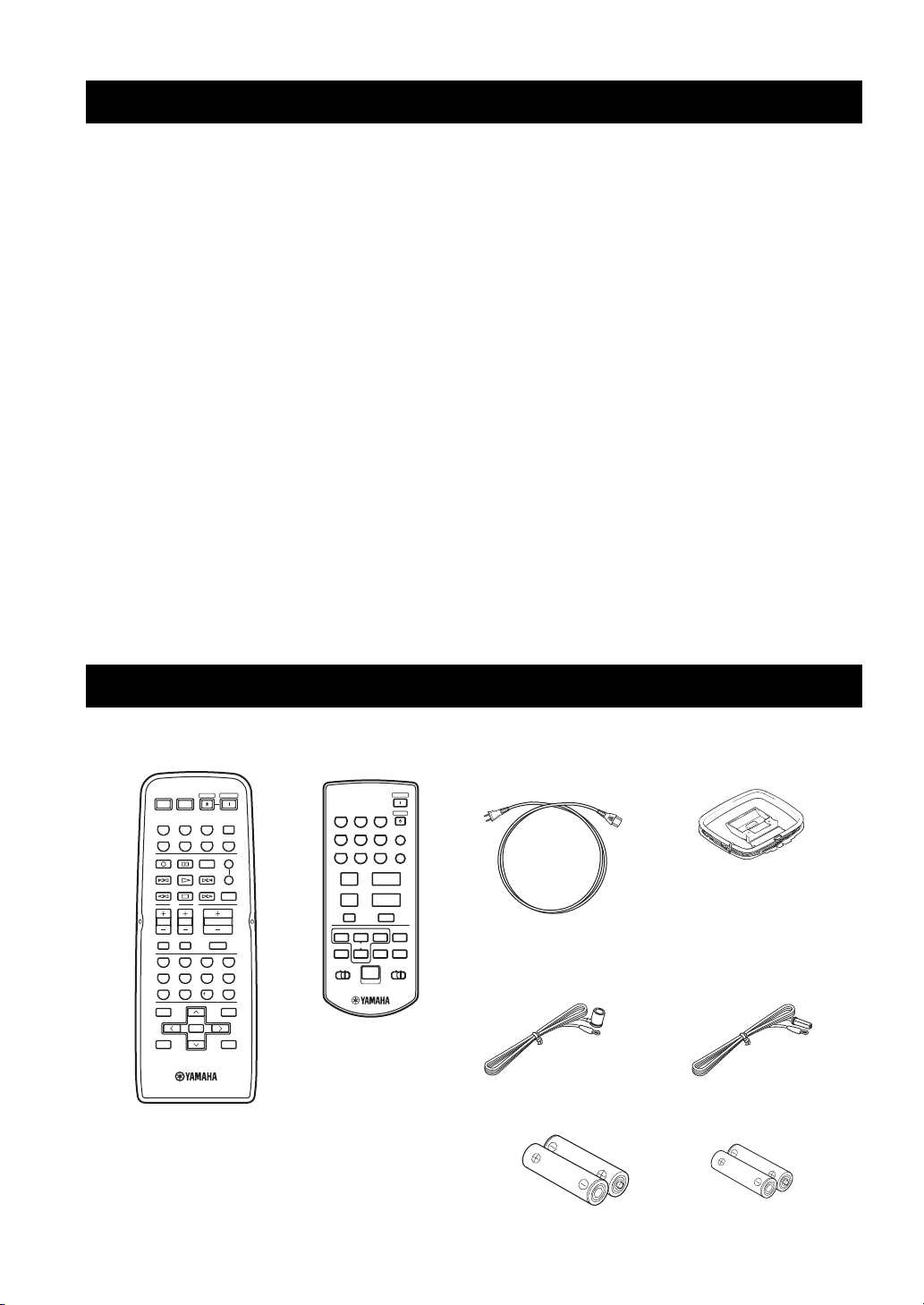
SUPPLIED ACCESSORIES
Please check that you received all of the following parts.
Remote control
POWER POWER
STANDBY
POWER
AVTV
CD
MD/TAPE
TUNER
XM
PHONODVD
VCR
DTV/CBL
REC
CODE SET
DISC SKIP
VOL C H
MUTE INPUT
BAND
A-E/CAT. A-E/CAT.
MEMORY
SPEAKERS
SLEEP
TV
VOLUME
MUTE
4321
81070965
ENT.
MENUTITLE
SRCH MODE
ENTER
DISPLAYRETURN
PRESET/CH
A
B
Zone 2 remote control Power cable
POWER
ZONE 2
PRESET
A/B/C/D/E
u
d
2
89
k
PRESET/CH
s
n
NUMBER
TUNER
A-E/CAT.h
3
6
VOLUME
MUTE
a
STANDBY
ENT
0
+
–
DISPLAY
CAT.
DISC
XMCDID2ID1
CD1PHONO
MD/TAPE4VCR5DTV/CBL
DVD7XM
lA-E/CAT.
wef
ALLpPRESET
b
(Two for Asia model)
Indoor FM antenna
(U.S.A., Canada and
General models)
Batteries (x2)
(AA, R6, UM-3)
AM loop antenna
Indoor FM antenna
(Europe and Australia
models)
Batteries (x2)
(AAA, R03, UM-4)
2
Page 7
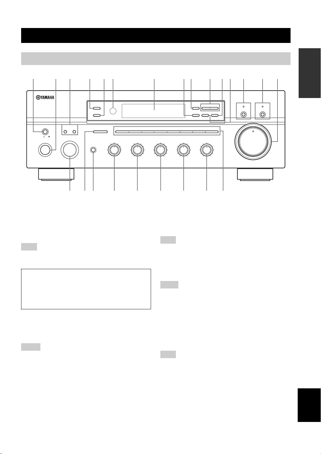
Front panel
12
20
60
26
40
16
-dB
CONTROLS AND FUNCTIONS
CONTROLS AND FUNCTIONS
INTRODUCTION
6312 5498AB7DC0
ZONE 2 ON/OFF
ZONE CONTROL
MASTER SPEAKERS
ON OFF
MAIN ZONE
ON/OFF
BA
INPUT
PHONES
A/B/C/D/E
CATEGORY
DTV/CBL
12345678
REC OUT
MD/TAPECDXM
VCR TUNER
DVD
BASS
101
22
3
PHONO
44
55
–
3
+
HGFIJKLMN
1 MASTER ON/OFF
Press inward to the ON position to turn on the power of
this unit. Press again to release it outward to the OFF
position to turn off this unit.
See page 17 for details.
Note
Even when this unit is turned off, this unit consumes a small
amount of power to preserve the memory.
Memory back-up
The memory back-up circuit prevents the stored data
from being lost. However, the stored data will be lost if
the power cord is disconnected from the AC wall outlet
for more than one week.
2 MAIN ZONE ON/OFF
Turns on Main Zone of this unit or sets it to the standby
mode.
See page 17 for details.
Notes
• This switch is operational only when MASTER ON/OFF is
pressed inward to the ON position.
• In the standby mode, this unit consumes a small amount of
power to receive infrared signals from the remote control.
3 SPEAKERS A/B
Turns on or off the speaker set connected to the
SPEAKERS A and/or SPEAKERS B terminals on the rear
panel each time the corresponding button is pressed (see
page 18).
l
TUNING/CH
h
MEMORY
TUN MODE/DISP
MAN'L/AUTO FM
AUTO/MAN'L
LOUDNESS
FLAT
1
–
30dB
210
3 9
48
57
6
VOLUME
CD DIRECT AMPPURE DIRECT
16
20
12
26
40
60
∞
8
4
2
0
-dB
TREBLE
101
22
3
3
44
55
+
–
FM/AM
XM/ANT
EDIT
SEARCH MODE
DISPLAY
BALANCE
101
22
3
3
44
55
R
L
(U.S.A. model)
4 ZONE 2 ON/OFF
Turns on Zone 2 or set it to the standby mode. When Zone
2 is turned on, signals are output at the ZONE 2 OUT
jacks.
Note
This switch is operational only when MASTER ON/OFF is
pressed inward to the ON position.
5 ZONE CONTROL
Press to control the input source of Zone 2.
Notes
• This button is operational only when Zone 2 is turned on.
• When you press this button, the ZONE 2 indicator flashes in the
front panel display for approximately 5 seconds. Select the
input source of Zone 2 while the indicator is flashing.
• You can select the preset station or channel when TUNER or
XM is selected as the input source of Zone 2.
6 Remote control sensor
Receives infrared signals from the remote control.
Note
Switch the remote control ID between ID1 and ID2 when using
multiple YAMAHA receivers or amplifiers (see pages 9, 39 and
40).
7 Front panel display
Shows information about the operational status of this
unit.
E
English
3
Page 8

CONTROLS AND FUNCTIONS
8 EDIT, SEARCH MODE
Exchanges the assignment of two preset stations with each
other when TUNER is selected as the input source (see
page 29).
Switches between search modes when XM is selected as
the input source (see page 33).
9 FM/AM, XM ANT (ANTENNA)
Switches the reception band between AM and FM when
TUNER is selected as the input source (see page 24).
Shows the reception level of the XM Connect-and-Play
digital antenna (sold separately) when XM is selected as
the input source (see page 31).
0 TUNING/CH l / h
Selects the tuning frequency when TUNER is selected as
the input source (see page 24).
Searches for a radio channel or selects the preset channel
number when XM is selected as the input source (see page
31).
A TUN (TUNING) MODE/DISP (DISPLAY)
Switches the tuning mode between automatic (the AUTO
indicator turns on as a result) and manual (the AUTO
indicator turns off as a result) when TUNER is selected as
the input source.
Switches the XM Satellite Radio information shown in the
front panel display between channel number/name,
category and artist name/song title when XM is selected as
the input source (see page 34).
B MEMORY
Stores a station in the system memory (see page 28).
Sets this unit to the automatic preset tuning mode (see
page 26).
Stores a radio channel in the system memory when XM is
selected as the input source (see page 37).
C PURE DIRECT and indicator
Allows you to listen to a source in the purest possible
sound. The indicator above it lights up when this function
is turned on.
See page 20 for details.
D CD DIRECT AMP and indicator
Allows you to listen to a CD source in the purest possible
sound. The indicator above it lights up and the front panel
display turns off when this function is turned on.
See page 20 for details.
E VOLUME
Increases or decreases the sound output level.
Note
This does not affect the OUT (REC) level.
F INPUT selector
Selects the input source you want to listen to or watch.
G A/B/C/D/E, CATEGORY
Selects the preset station group (A to E) when TUNER is
selected as the input source (see page 27).
Switches between channel categories or selects the preset
channel group when XM is selected as the input source
(see page 35).
H PHONES jack
Outputs audio for private listening with your headphones.
Note
Press SPEAKERS A/B so that the SP A/B indicators turn off
before you connect your headphones to the PHONES jack.
I REC OUT selector
Selects a source for recording to the MD recorder or the
tape deck independently of the INPUT selector setting,
allowing you to record the selected source while listening
to another source (see page 21).
J BASS
Increases or decreases the low frequency response. The 0
position produces a flat response (see page 20).
K TREBLE
Increases or decreases the high frequency response. The 0
position produces a flat response (see page 20).
L BALANCE
Adjusts the sound output balance of the left and right
speakers to compensate for sound imbalances caused by
speaker locations or listening room conditions (see page
20).
M LOUDNESS
Retains a full tonal range at any volume level to
compensate for the human ears’ loss of sensitivity to high
and low-frequency ranges at a low volume level (see page
20).
N Preset station/channel number buttons
(1 to 8)
Selects the preset station/channel number (1 to 8) directly
when TUNER or XM is selected as the input source (see
page 29).
Note
The XM Satellite Radio features (XM ANT, CH, SEARCH
MODE, DISP, CATEGORY, MEMORY and the preset channel
number buttons) are only applicable to the U.S.A. model and are
operational only when XM is selected as the input source. For
details, see “XM SATELLITE RADIO TUNING” on page 30.
4
Page 9
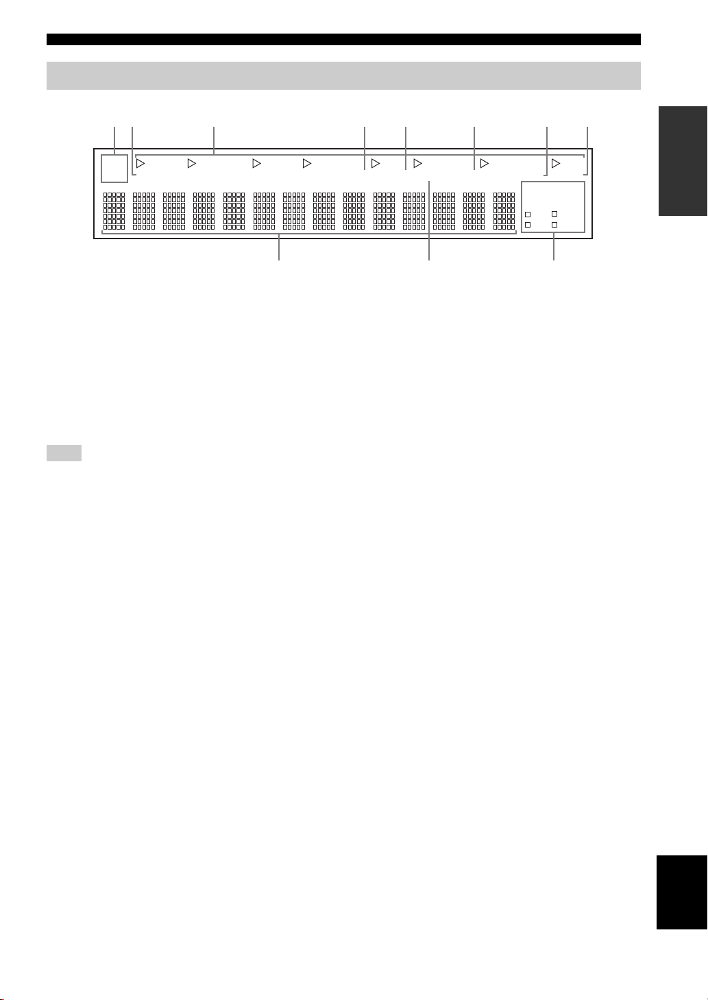
Front panel display
0A9
CONTROLS AND FUNCTIONS
12 4 5 6 738
SP
A B
DVD VCR CD TUNER PHONO
ZONE2 ZONE3 MEMORY AUTO
DTV/CBL
MD/TAPE
1 SP (SPEAKERS) A/B indicators
Light up according to the set of speakers selected.
Both indicators light up when both sets of speakers are
selected.
2 ZONE 2 indicator
Lights up when Zone 2 is turned on.
3 Input source indicators
Light up when this unit is in the corresponding mode.
Note
The XM indicator is only applicable to the U.S.A. model.
4 MEMORY indicator
Flashes for approximately 5 seconds after MEMORY on
the front panel is pressed. While the MEMORY indicator
is flashing, store the displayed station in the system
memory by using A/B/C/D/E and one of the preset station
number buttons on the front panel.
5 AUTO indicator
Lights up when this unit is in the automatic tuning mode.
6 STEREO indicator
Lights up when this unit is receiving a strong signal for an
FM stereo broadcast while the AUTO indicator is lit.
TUNED STEREO
SLEEP
MUTE
HOLDPTY
XM
EON
PTY
PS
RT
CT
7 SLEEP indicator
Lights up when the sleep timer is turned on.
8 MUTE indicator
Flashes while the MUTE function is turned on.
9 Multi-information display
Shows information when adjusting or changing settings.
0 TUNED indicator
Lights up when this unit is tuned into a station.
■ Europe model only
A Radio Data System indicators
The box-shaped indicator beside the name of each Radio
Data System mode lights up when the corresponding
Radio Data System mode is selected.
PTY HOLD indicator
Lights up while searching for stations in the PTY
SEEK mode.
EON indicator
Lights up when the Radio Data System station that
offers the EON data service is being received.
INTRODUCTION
English
5
Page 10
CONTROLS AND FUNCTIONS
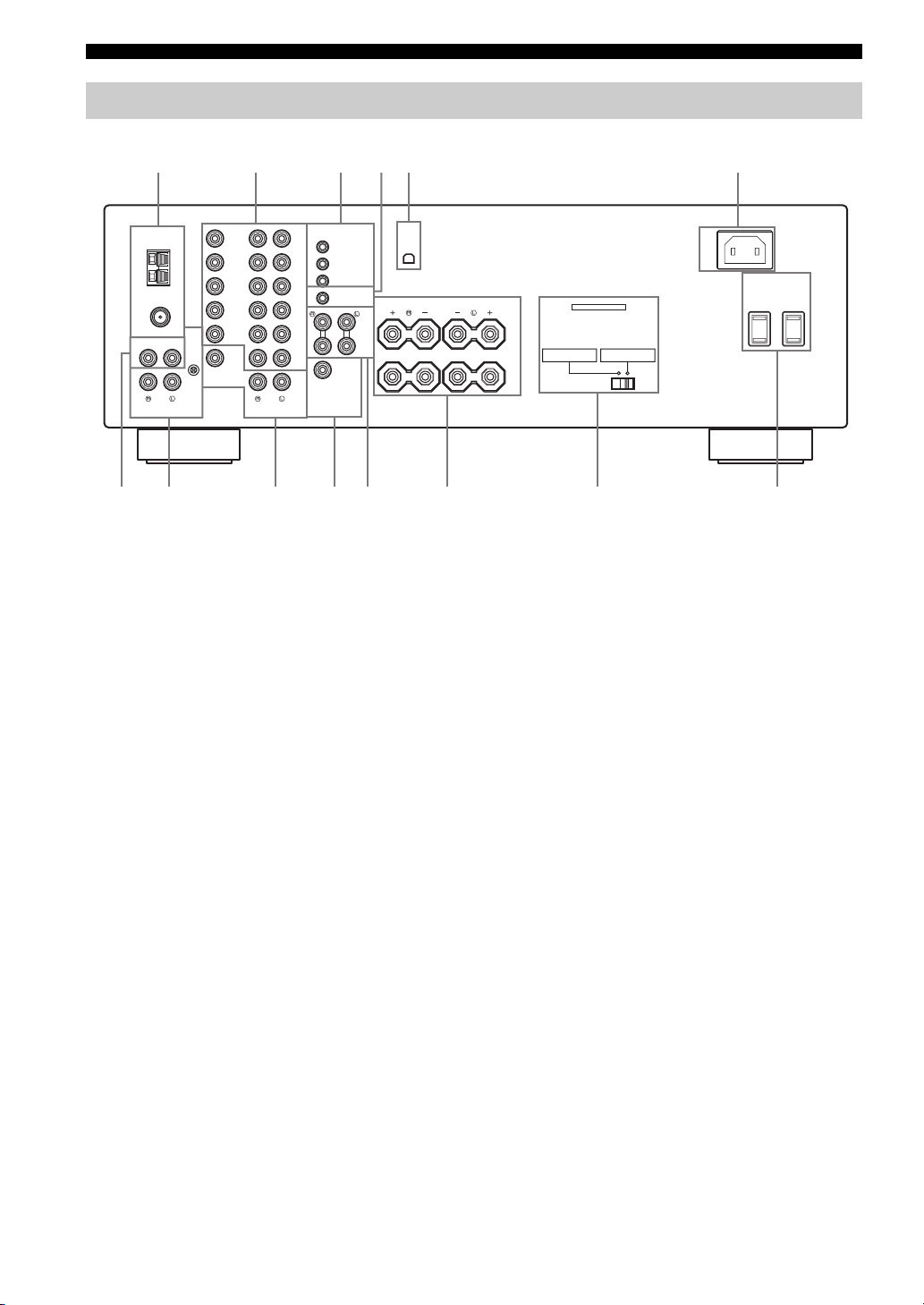
Rear panel
1235 6
TUNER
75Ω
UNBAL.
CD
PHONO
70 CD8AB
DVD
GND
DTV/
CBL
AM
ANT
FM
ANT
IN
VCR
OUT
MONITOR
GND
OUT
ZONE 2
OUT
VIDEO
DVD
DTV/
CBL
IN
VCR
OUT
IN
(PLAY)
MD/
TAPE
OUT
(REC)
ZONE 2
OUT
9
1 Antenna terminals
Connect FM and AM antennas.
See page 14 for connections information.
2 AUDIO/VIDEO jacks
Connect audio and video components.
See page 13 for connection information.
3 REMOTE jacks
These jacks are used to input/output remote control
signals.
See page 41 for connection information.
4 CONTROL OUT jack
This is a control expansion jack. Consult your nearest
authorized YAMAHA dealer or service center about this
jack.
5 XM jack
(U.S.A. model only)
Connect XM Connect-and-Play digital antenna accessory.
See page 30 for connection information.
6 AC IN
Use to plug in the supplied power cable.
See page 16 for connection information.
7 CD jacks
Connect a CD player.
See page 13 for connection information.
IN
OUT
IN
CONTROL OUT
+12V 15mA MAX.
COUPLER
SUB
WOOFER
OUTPUTAUDIOAUDIO
4
XMREMOTE
1
2
SPEAKERS
MAIN
IN
PRE
OUT
CLASS 2 WIRING
A
B
SELECTEUR D'IMPEDANCE
A OR B: 4ΩMIN. /SPEAKER
A+B: 8ΩMIN. /SPEAKER
8 PHONO jacks and GND terminal
Connect a turntable.
See page 13 for connection information.
9 ZONE 2 jacks
Connect a Zone 2 component.
See page 41 for connection information.
0 SUBWOOFER OUTPUT jack
Connect a subwoofer with built-in amplifier.
A COUPLER jacks
Connect an external unit.
See page 16 for connection information.
B SPEAKERS terminals
Connect speakers.
See page 12 for connection information.
C IMPEDANCE SELECTOR switch
Switches the impedance setting.
See page 16 for details.
D AC OUTLET(S) (SWITCHED)
Use to supply power to your other audio and video
components.
See page 16 for details.
■ Asia and General models only
VOLTAGE SEL E CTO R
See page 16 for details.
(U.S.A. model)
IMPEDANCE SELECTOR
SET BEFORE POWER ON
A OR B: 6ΩMIN. /SPEAKER
AC IN
AC OUTLETS
SWITCHED
6
Page 11
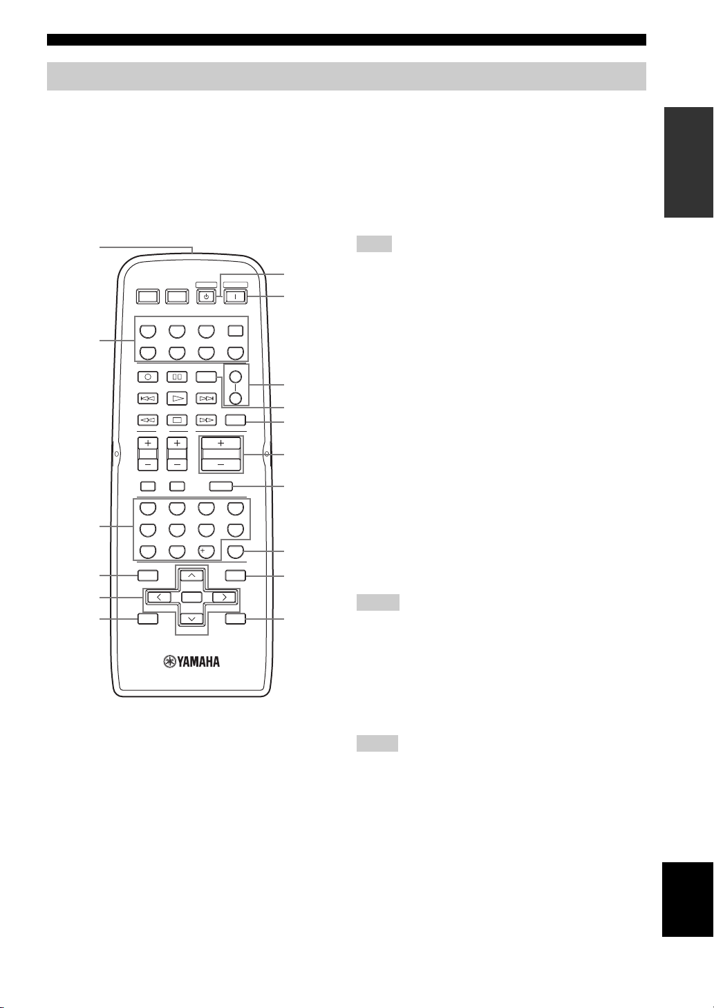
Remote control
CONTROLS AND FUNCTIONS
This section describes the function of each button on the
remote control used to control this unit or other
components made by YAMAHA or other manufacturers.
The functions of the buttons used to control your other
audio and video components are the same as those of the
corresponding buttons on those components. Refer to
those components’ instruction manuals for details. To
operate other components using this remote control, see
“REMOTE CONTROL FEATURES” on page 43.
1
7
8
A
9
B
0
A
B
C
D
E
F
2
3
4
5
6
POWER POWER
AVTV
CD
MD/TAPE
DTV/CBL
REC
DISC SKIP
TV
VOL CH
MUTE INPUT
65
09
BAND
MEMORY
ENTER
A-E/CAT. A-E/CAT.
PRESET/CH
(U.S.A. model)
STANDBY
TUNER
VCR
CODE SET
VOLUME
7
10
MUTE
POWER
XM
PHONODVD
SPEAKERS
SLEEP
4321
8
ENT.
MENUTITLE
SRCH MODE
DISPLAYRETURN
1 Infrared signal transmitter
Sends infrared signals.
2 Input selector buttons
Select the desired input source and change the control area
(see page 43).
3 Numeric buttons
Select the preset station number (1 to 8) when TUNER is
selected as the input source.
Select the preset channel number when XM is selected as
the input source.
4 BAND
Switches to the previously used reception band (FM or
AM) when TUNER is selected as the input source.
Note
The frequency of the previously received station is automatically
recalled.
5 A-E/CAT. (CATEGORY) j / i
Selects the preset station group (A to E) when TUNER
is selected as the input source (see page 29).
Switches between channel categories or selects the
preset channel group (A to E) when XM is selected as
the input source (see page 35).
PRESET/CH u / d
Selects the preset station number (1 to 8) when
TUNER is selected as the input source (see page 29).
Searches for a radio channel or selects the preset
channel number (1 to 8) when XM is selected as the
input source (see page 33).
6 MEMORY
Stores a radio channel in the system memory when XM is
selected as the input source (see page 37).
7 STANDBY
Sets this unit to the standby mode.
Notes
• This button is operational only when MASTER ON/OFF on the
front panel is pressed inward to the ON position.
• In the standby mode, this unit consumes a small amount of
power to receive infrared signals from the remote control.
• This button does not set Zone 2 to the standby mode.
8 POWER
Turns on this unit.
Notes
• This button is operational only when MASTER ON/OFF on the
front panel is pressed inward to the ON position.
• This button does not turn on Zone 2.
INTRODUCTION
7
English
Page 12

CONTROLS AND FUNCTIONS
9 SPEAKERS A/B
Turns on or off the set of speakers connected to the
SPEAKERS A and/or SPEAKERS B terminals on the rear
panel of this unit when the corresponding button is
pressed each time.
0 CODE SET
Use to set up remote control codes (see page 45).
A SLEEP
Sets the sleep timer.
B VOLUME +/–
Increases or decreases the sound output level.
Notes
• This does not affect the OUT (REC) level.
• When you press VOLUME +/– to control the sound output
level of this unit, VOLUME on the front panel rotates.
C MUTE
Mutes the sound output. Press again to restore the sound
output to the previous volume level (see page 23).
Note
The sound output to Zone 2 is not muted.
D ENT. (ENTER)
Confirms an entered channel number during the Direct
Number Access mode when XM is selected as the input
source.
E SRCH (SEARCH) MODE
Switches between the XM Satellite Radio search modes
(see page 35) when XM is selected as the input source.
F DISPLAY
Switches the XM Satellite Radio information shown in the
front panel display between channel number/name,
category and artist name/song title when XM is selected as
the input source.
Note
The XM Satellite Radio features (XM, SRCH MODE, DISPLAY,
A-E/CAT. j / i, PRESET/CH u / d, MEMORY and ENT.) are
only applicable to the U.S.A. model and are operational only
when XM is selected as the input source. For details, see “XM
SATELLITE RADIO TUNING” on page 30.
8
Page 13
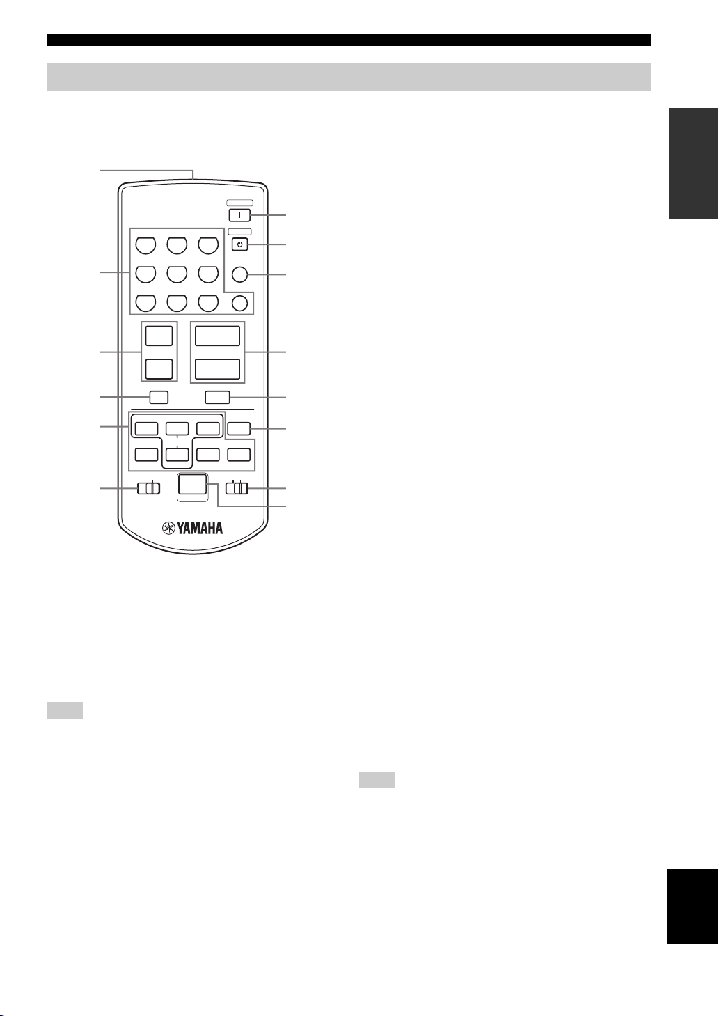
Zone 2 remote control
CONTROLS AND FUNCTIONS
This section describes the function of each button on the
Zone 2 remote control used to control Zone 2. You can
also use the Zone 2 remote control to control the XM
Satellite Radio features and YAMAHA CD players.
1
TUNER
A-E/CAT.h
PRESET
p
3
6
+
VOLUME
–
MUTE
f
a
POWER
STANDBY
ENT
0
DISPLAY
CAT.
DISC
7
8
9
0
A
B
XMCDID2ID1
C
D
2
3
4
5
6
ZONE 2
CD1PHONO
2
MD/TAPE4VCR5DTV/CBL
DVD7XM
89
u
PRESET
d
A/B/C/D/E
k
lA-E/CAT.
w
e
PRESET/CH
ALL
s
b
n
NUMBER
(U.S.A. model)
1 Infrared signal transmitter
Sends infrared signals.
2 Input selector/numeric buttons
Select the desired input source of Zone 2.
Enter a channel number or preset channel number when
XM is selected as the input source.
Note
You must press and hold NUMBER before you press any of these
buttons to enter numbers.
3 PRESET u / d
Selects the preset station number (1 to 8) when TUNER is
selected as the input source.
4 A/B/C/D/E
Selects the preset station group (A to E) when TUNER is
selected as the input source.
5 XM Satellite Radio control buttons
Controls the XM Satellite Radio features when the
CD/XM switch is slid to the XM position.
A-E/CAT. (CATEGORY) l / h
Switches between channel categories or selects the
preset channel group (A to E) when XM is selected as
the input source.
PRESET/CH k / n
Searches for a radio channel or selects the preset
channel number (1 to 8) when XM is selected as the
input source.
ALL
Selects the All Channel Search mode.
PRESET
Selects the Preset Search mode.
CAT. (CATEGORY)
Selects the Category Search mode.
6 ID1/ID2 switch
Switches the remote control ID between ID1 and ID2 (see
page 40).
7 POWER
Turns on Zone 2.
8 STANDBY
Sets Zone 2 to the standby mode.
9 ENT (ENTER)
Confirms an entered channel number during the Direct
Number Access mode when XM is selected as the input
source.
0 VOLUME +/–
Increases or decreases the sound output level of Zone 2.
INTRODUCTION
Note
This does not affect the OUT (REC) level.
English
9
Page 14

CONTROLS AND FUNCTIONS
A MUTE
Mutes the sound output to Zone 2. Press again to restore
the sound output to the previous volume level.
B DISPLAY
Switches the XM Satellite Radio information displayed in
the front panel display between channel number/name,
category and artist name/song title when XM is selected as
the input source.
C CD/XM switch
Switches the function of the control buttons numbered 5,
B and D between controlling YAMAHA CD players and
controlling the XM Satellite Radio features.
D NUMBER
Press and hold before you press the input selector/numeric
buttons to enter numbers to control the XM Satellite Radio
features.
Note
The XM Satellite Radio features (XM, ENT, DISPLAY and the
XM Satellite Radio control buttons) are only applicable to the
U.S.A. model and are operational only when XM is selected as
the input source and the CD/XM switch is slid to the XM
position. For details, see “XM SATELLITE RADIO TUNING”
on page 30.
10
Page 15
Installing batteries in the remote controls
CONTROLS AND FUNCTIONS
■ Notes on batteries
• Change all of the batteries if the operation range of the remote controls decreases.
• Use AA, R6, UM-3 batteries for the remote control and AAA, R03, UM-4 batteries for the Zone 2 remote control.
• Make sure that the polarities are correct. See the illustration inside the battery compartment of each remote control.
• Remove the batteries if the remote controls are not used for an extended period of time.
• Do not use old batteries together with new ones.
• Do not use different types of batteries (such as alkaline and manganese batteries) together. Read the packaging carefully as these
different types of batteries may have the same shape and color.
• We strongly recommend using alkaline batteries.
• If the batteries have leaked, dispose of them immediately. Avoid touching the leaked material or letting it come into contact with
clothing, etc. Clean the battery compartment thoroughly before installing new batteries.
• Do not throw away batteries with general house waste; dispose of them correctly in accordance with your local regulations.
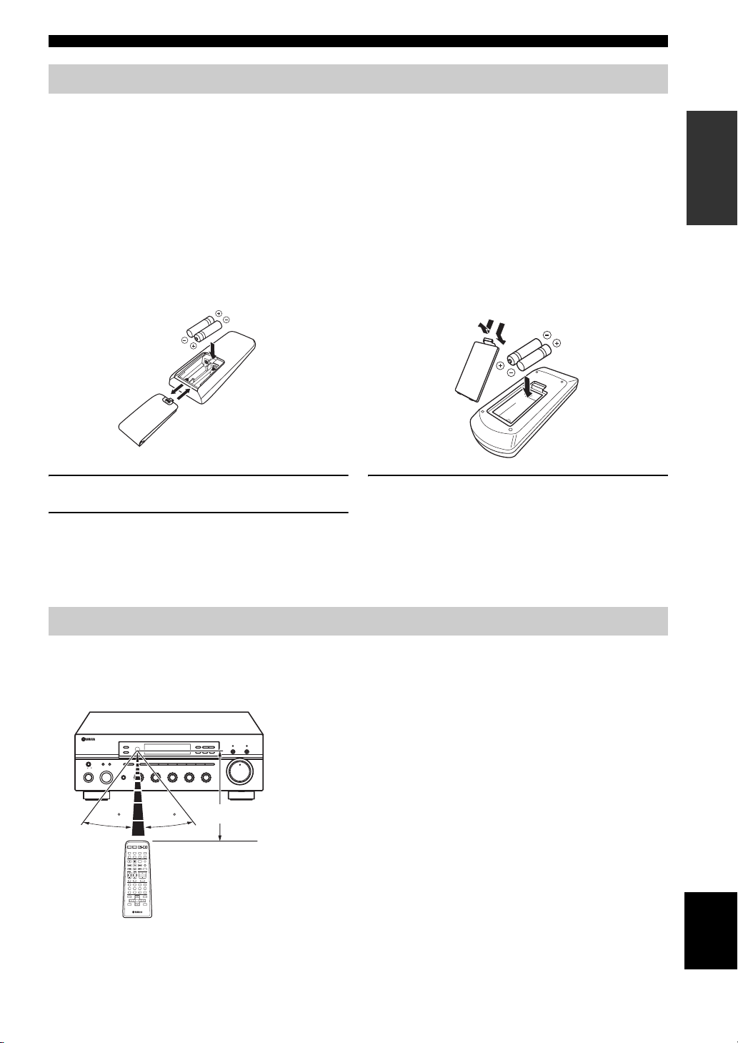
Remote control Zone 2 remote control
1
3
2
1
3
1 Open the battery compartment cover.
3 Close the cover back.
2
2 Insert the supplied batteries in each remote
control according to the polarity markings (+
and –) on the inside of the battery
compartment.
INTRODUCTION
Using the remote controls
The remote controls transmit a directional infrared beam.
Be sure to aim the remote controls directly at the remote control sensor on the front panel of this unit or on the infrared
signal receiver in Zone 2 during operation.
■ Handling the remote controls
• The area between the remote controls and this unit (or the
infrared signal receiver in Zone 2) must be clear of large
obstacles.
• Do not spill water or other liquids on the remote controls.
• Do not drop the remote controls.
• Do not leave or store the remote controls in the following types
of conditions:
– places of high humidity, such as near a bath
– places of high temperature, such as near a heater or a stove
– places of extremely low temperatures
– dusty places
• Do not expose the remote control sensor to strong lighting, in
particular, an inverter type fluorescent lamp; otherwise, the
remote controls may not work properly. If necessary, position
this unit away from direct lighting.
11
MASTER SPEAKERS
ON OFF
MAIN ZONE
ON/OFF
BA
INPUT
ZONE 2 ON/OFF
ZONE CONTROL
A/B/C/D/E
CATEGORY
REC OUT
MD/TAPECDXM
PHONES
VCR TUNER
DTV/CBL
DVD
POWER POWER
STANDBY
AVTV
CD
MD/TAPE
TUNER
VCR
DTV/CBL
REC
AUDIO
DISC SKIP
TV
VOL CH
VOLUME
MUTE INPUT
MUTE
ENTER
A-E/CAT. A-E/CAT.
MEMORY
PRESET/CH
12345678
BASS
TREBLE
BALANCE
101
101
101
22
22
22
3
3
PHONO
3
3
3
44
44
44
55
+
–
55
+
–
55
L
30 30
POWER
XM
PHONODVD
SPEAKERS
A
B
SLEEP
4321
81070965
ENT.
MENUTITLE
SRCH MODEBAND
DISPLAYRETURN
l
TUNING/CH
h
R
FM/AM
XM/ANT
EDIT
SEARCH MODE
3
210
3
48
MEMORY
MAN'L/AUTO FM
LOUDNESS
1
57
CD DIRECT AMPPURE DIRECT
TUN MODE/DISP
AUTO/MAN'L
VOLUME
FLAT
–
30dB
9
6
Approximately 6 m (19.7 ft)
English
Page 16
CONNECTIONS
CONNECTIONS
Connecting speakers
Be sure to connect the left channel (L), right channel (R), “+” (red) and “–” (black) properly. If the connections are faulty,
no sound will be heard from the speakers, and if the polarity of the speaker connections is incorrect, the sound will be
unnatural and lack bass.
CAUTION
• Before connecting the speakers, make sure that the power of this unit is turned off.
• Do not let the bare speaker wires touch each other or do not let them touch any metal part of this unit. This could
damage this unit and/or the speakers.
• Use magnetically shielded speakers. If this type of speakers still creates the interference with the monitor, place the
speakers away from the monitor.
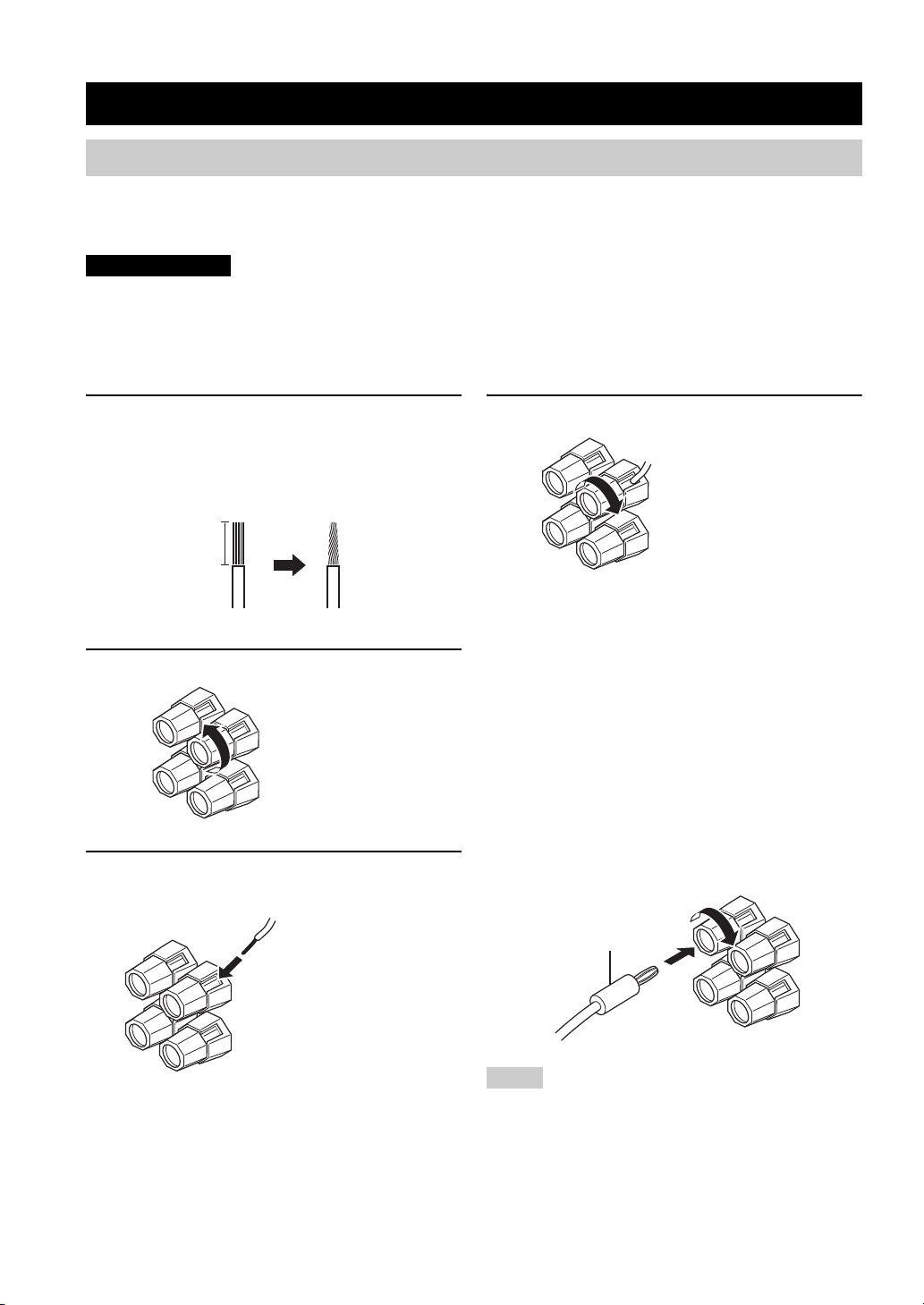
1 Remove approximately 10 mm (3/8 in) of
insulation from the end of each speaker
cable and twist the exposed wires of the
cable together to eliminate the risk of a
short-circuit.
10 mm (3/8 in)
2 Unscrew the knob.
Red: positive (+)
Black: negative (–)
3 Insert one bare wire into the hole in the side
of each terminal.
4 Tighten the knob to secure the wire.
Red: positive (+)
Black: negative (–)
■ Notes on the speaker cord
A speaker cord is actually a pair of insulated cables
running side by side. One cable is colored or shaped
differently, perhaps with a stripe, groove or ridge. Connect
the striped, grooved or ridged cable to the “+” (red)
terminals on this unit and your speaker. Connect the plain
cable to the “–” (black) terminals on this unit and your
speaker.
■ Connecting the banana plug
(U.S.A., Canada, Australia and General
models only)
First, tighten the knob and then insert the banana plug into
the end of the corresponding terminal.
12
Banana plug
Red: positive (+)
Black: negative (–)
Notes
• One or two speaker sets can be connected to this unit. If you use
only one speaker set, connect it to either the SPEAKERS A or
SPEAKERS B terminals.
• Use speakers with the specified impedance shown on the rear
panel of this unit.
Page 17
CONNECTIONS
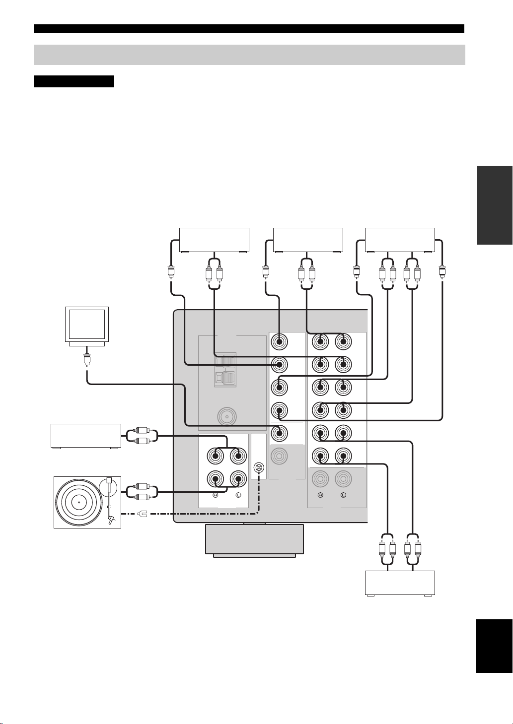
Connecting audio and video components
CAUTION
• Do not connect this unit or other components to the main power until all connections between components are complete.
• All connections must be correct: L (left) to L, R (right) to R, “+” to “+” and “–” to “–”. Also, refer to the owner’s manual for each of
your components.
• Use the RCA type pin plug cables for audio and video components except speakers.
y
• The PHONO jacks are designed to connect a turntable with an MM or high-output MC cartridge. If you have a turntable with a lowoutput MC cartridge, use an in-line boosting transformer or an MC-head amplifier when connecting your turntable to the PHONO
jacks.
• Connect your turntable to the GND terminal to reduce noise in the signal. However, you may hear less noise without the connection to
the GND terminal for some record players.
PREPARATION
Video
monitor
Video in
V
CD player
Turn ta bl e
Audio out
L
R
Audio out
R
L
GND
V
Video out
Digital TV,
Cable TV
TUNER
75Ω
UNBAL.
CD
PHONO
DVD player
Audio out
GND
AM
ANT
FM
ANT
GND
Video out
V
VIDEO
DVD
DTV/
CBL
IN
VCR
OUT
MONITOR
OUT
ZONE 2
OUT
Audio out
LRLR
(PLAY)
TAP E
ZONE 2
AUDIOAUDIO
VCR, etc.
Audio in
Video out
V V
DVD
DTV/
CBL
IN
VCR
OUT
IN
MD/
OUT
(REC)
OUT
Audio out
LR LR
Video in
R
R
L
L
Audio in Audio out
MD recorder,
Tape deck, etc.
English
13
Page 18
CONNECTIONS
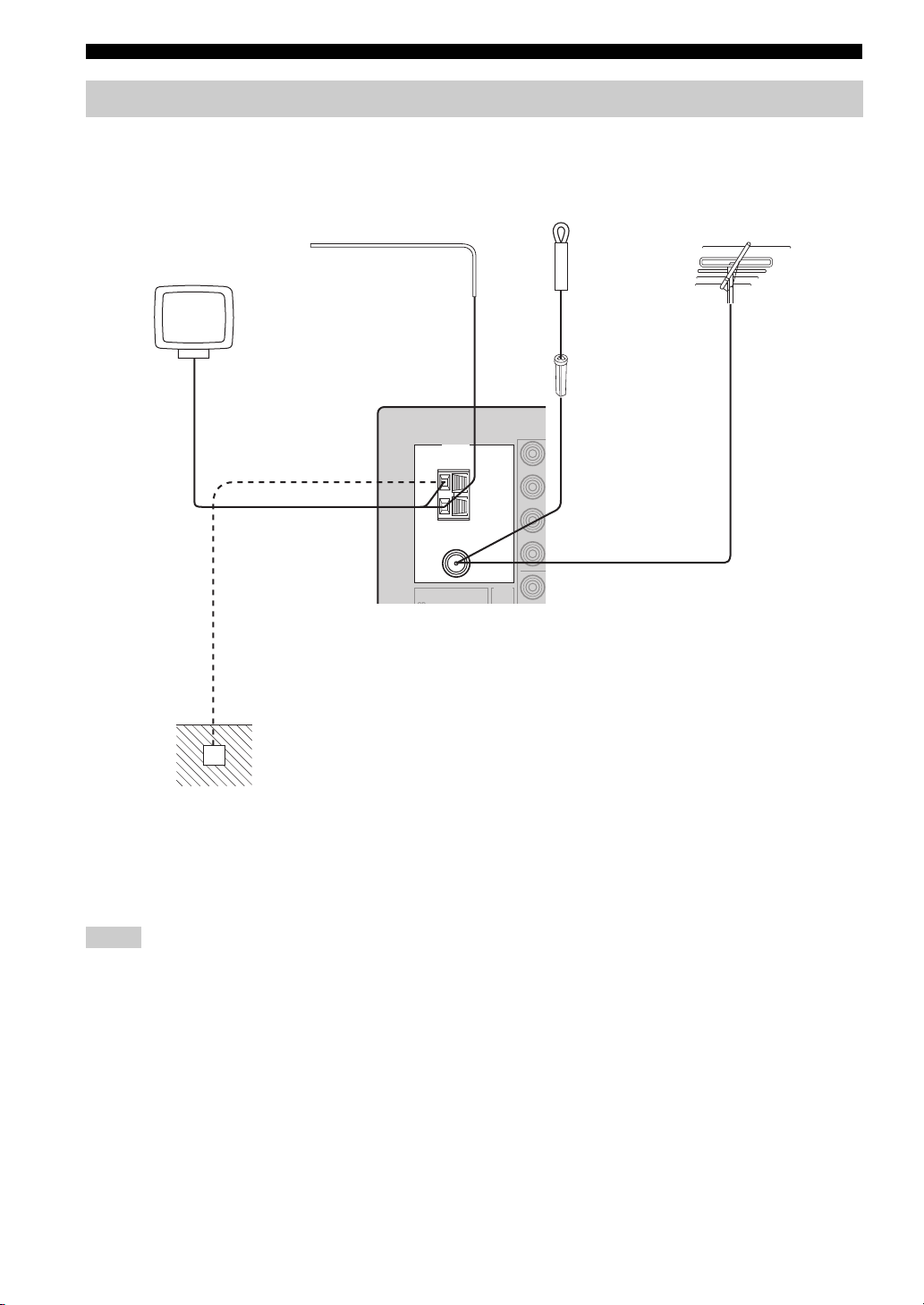
Connecting the AM and FM antennas
Both AM and FM indoor antennas are included with this unit. In general, these antennas should provide sufficient signal
strength. Connect each antenna correctly to the designated terminals.
AM loop antenna
(included)
Outdoor AM antenna
Use a 5 to 10 m of vinylcovered wire extended
outdoors from a window.
TUNER
Indoor FM antenna
(included)
GND
AM
ANT
Outdoor FM antenna
75Ω
UNBAL.
FM
ANT
GND
Ground (GND terminal)
For maximum safety and
minimum interference, connect
the antenna GND terminal to a
good earth ground. A good earth
ground is a metal stake driven into
moist earth.
Notes
• A properly installed outdoor antenna provides clearer reception than an indoor one. If you experience poor reception quality, an
outdoor antenna may improve the quality. Consult your nearest authorized YAMAHA dealer or service center about outdoor antennas.
• If you connect an outdoor FM antenna to this unit, do not connect the indoor FM antenna to this unit.
• To minimize interference from automobile ignition, locate the antenna as far from heavy traffic as possible.
• Keep the feeder cable or coaxial cable as short as possible. Do not bundle or roll up excess cable.
• The antenna should be placed at least 2 meters from reinforced concrete walls or metal structures.
14
Page 19
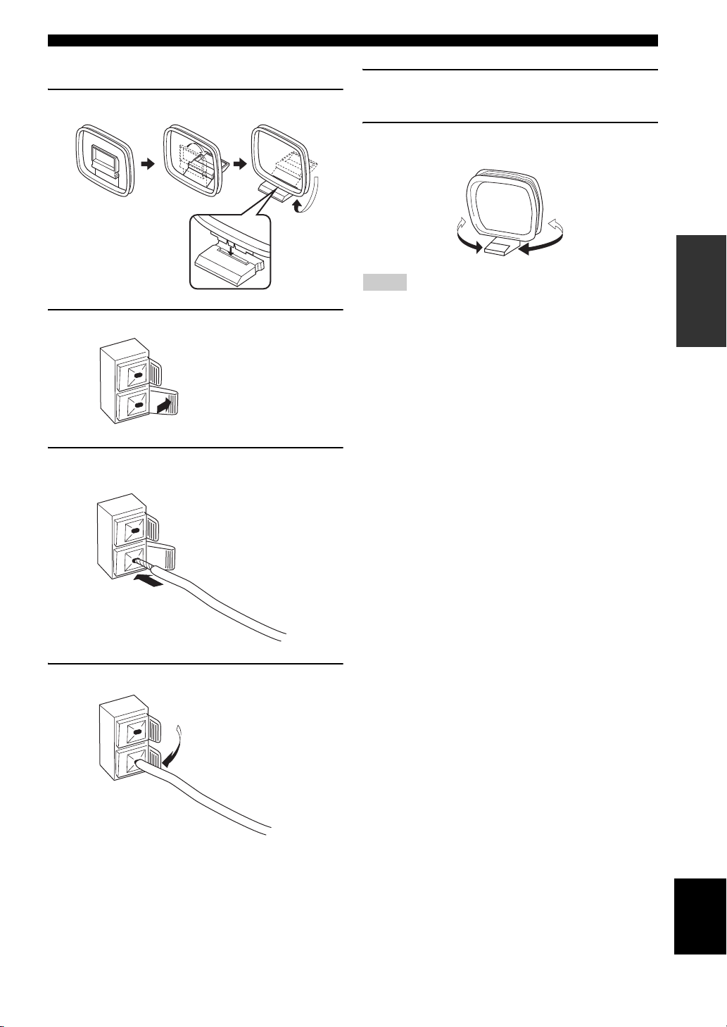
■ Connecting the AM loop antenna
1 Set up the AM loop antenna.
2 Press and hold the tab.
CONNECTIONS
5 Repeat steps 2 to 4 to insert the AM loop
antenna lead wires into the GND terminal.
6 Orient the AM loop antenna for the best
reception.
PREPARATION
Notes
• The AM loop antenna should be placed away from this unit.
• A properly installed outdoor antenna provides clearer reception
than an indoor one. If you experience poor reception quality, an
outdoor antenna may improve the quality. It is recommended
that you should connect a 5 to 10 m of vinyl-covered wire to the
AM ANT terminal and extend it outdoors from a window.
Consult your nearest authorized YAMAHA dealer or service
center about outdoor antennas.
• The AM loop antenna should always be connected, even if an
outdoor AM antenna is connected to this unit.
3 Insert the AM loop antenna lead wires into
the AM ANT terminal.
4 Release the tab.
15
English
Page 20
CONNECTIONS
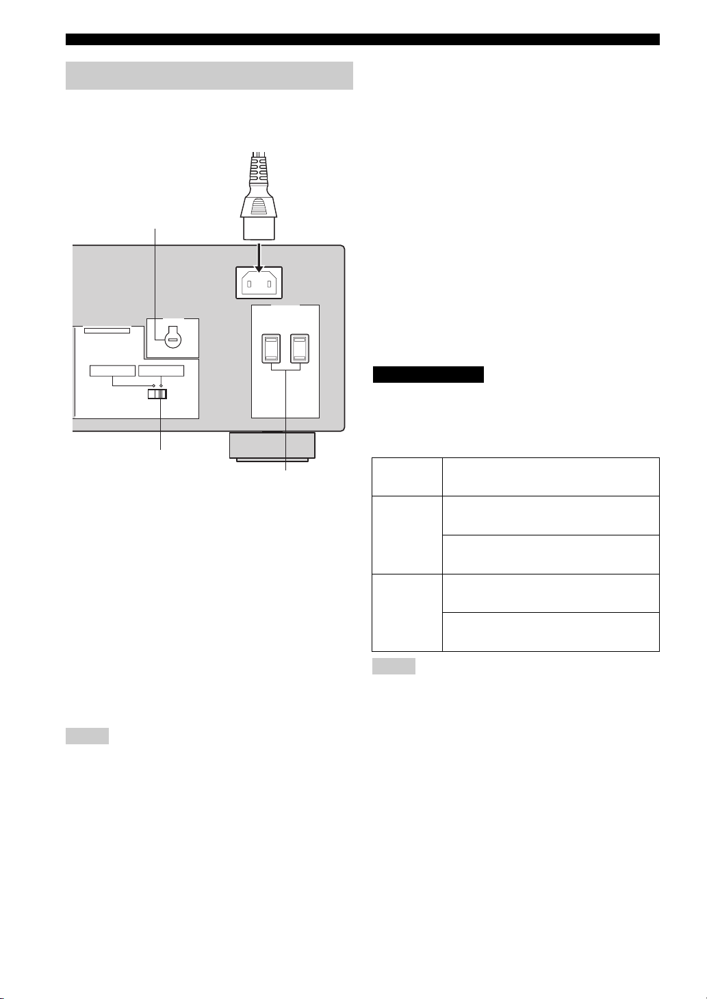
Connecting the power supply cord
Plug the power cable into the AC IN on the rear panel of
this unit and then plug the power supply cord into the AC
wall outlet after all other connections are complete.
Power cable
■ AC OUTLET(S) (SWITCHED)
Australia model ......................................................1 outlet
Other models ....................................................... 2 outlets
Use these outlets to connect the power supply cords from
your other components to this unit. The outlets supply
power to any connected components whenever the power
of this unit is turned on. For information on the maximum
power (total power consumption of components), see
“SPECIFICATIONS” on page 49.
VOLTAGE SELECTOR
AC IN
AC OUTLETS
SWITCHED
AC OUTLET(S)
IMPEDANCE SELECTOR
SET BEFORE POWER ON
SELECTEUR D'IMPEDANCE
A OR B: 4ΩMIN. /SPEAKER
A+B: 8ΩMIN. /SPEAKER
(General model)
A OR B: 6ΩMIN. /SPEAKER
IMPEDANCE SELECTOR
switch
VOLTAGE
SELECTOR
■ COUPLER jacks
Removing the jumper pins from the PRE OUT/MAIN IN
jacks enables this unit to operate separately as a control
amplifier or a power amplifier. These jacks are used to
connect a signal-processing system such as a graphic
equalizer or a surround-sound processor to this unit. If
such an external unit is connected to these jacks, the
VOLUME control of this unit can be used to adjust the
overall sound output level.
To connect an external unit, first remove the jumper pins
from the PRE OUT/MAIN IN jacks and then connect the
input jacks of that external unit to the PRE OUT jacks or
its output jacks to the MAIN IN jacks. For details, refer to
the owner’s manual included with the external unit to be
connected.
Notes
• When you do not use the COUPLER jacks, never remove the
jumper pins from these jacks. If removed, no sound will be
output from this unit.
• When you use this unit with an external unit connected to the
COUPLER jacks, make sure that the CD DIRECT AMP button
and the PURE DIRECT button on the front panel are turned off.
• When you use this unit as a power amplifier, connect the output
jacks of an external control amplifier, etc. to the MAIN IN jacks
of this unit. In this case, the controls of this unit will not
function except the PHONES jack and the SPEAKERS A/B
buttons. Use the controls on the external control amplifier to
make volume adjustments, etc.
■ VOLTAGE SELECTOR
(Asia and General models only)
VOLTAGE SELECTOR on the rear panel of this unit must
be set for your local main voltage BEFORE plugging the
power supply cord into the AC wall outlet.
Voltages are as follows:
Asia model......................... AC 220/230–240 V, 50/60 Hz
General model...... AC 110/120/220/230–240 V, 50/60 Hz
■ IMPEDANCE SELECTOR switch
CAUTION
Do not slide the IMPEDANCE SELECTOR switch while the
power of this unit is turned on, as doing so may damage the unit.
Select the switch position (left or right) according to the
impedance of the speakers in your system.
Switch
position
If you use one set (A or B), the impedance of
each speaker must be 6
Right
If you use two sets (A and B), the impedance
of each speaker must be 12
If you use one set (A or B), the impedance of
each speaker must be 4
Left
If you use two sets (A and B), the impedance
of each speaker must be 8
Notes
• The Canada model cannot use two separate speaker sets (A and
B) simultaneously when the IMPEDANCE SELECTOR switch
is slid to the 6
• If this unit fails to turn on, the IMPEDANCE SELECTOR
switch may not be fully slid to either position. If this is the case,
slide the switch all the way to either position when the power
supply to this unit is completely cut off.
Ω position.
Impedance level
Ω or higher.
Ω or higher.
Ω or higher.
Ω or higher.
16
Page 21

CONNECTIONS
12
20
60
26
40
16
-dB
Turning on and off this unit
When all connections are complete, turn on the power of
this unit.
1
l
TUNING/CH
MASTER SPEAKERS
ON OFF
MAIN ZONE
ON/OFF
ZONE 2 ON/OFF
ZONE CONTROL
BA
A/B/C/D/E
12345678
CATEGORY
INPUT
REC OUT
MD/TAPECDXM
PHONES
VCR TUNER
DTV/CBL
DVD
22
PHONO
3
44
BASS
101
55
–
3
+
TREBLE
101
22
3
44
55
+
–
22
3
3
44
BALANCE
101
55
L
FM/AM
XM/ANT
EDIT
SEARCH MODE
3
R
h
MEMORY
TUN MODE/DISP
MAN'L/AUTO FM
AUTO/MAN'L
LOUDNESS
FLAT
1
–
30dB
210
3
9
48
57
6
CD DIRECT AMPPURE DIRECT
16
20
12
VOLUME
26
8
40
4
2
60
0
∞
-dB
1 Press MASTER ON/OFF on the front panel
inward to the ON position to turn on the
power of this unit.
MASTER
ON OFF
Main Zone of this unit turns on.
You can set Main Zone of this unit to the standby
mode by pressing MAIN ZONE ON/OFF on the front
panel or STANDBY on the remote control.
Press MAIN ZONE ON/OFF on the front panel or
POWER on the remote control to turn Main Zone of
this unit on again.
Press MASTER ON/OFF on the front panel again to
release it outward to the OFF position to turn off this
unit.
y
While MASTER ON/OFF on the front panel is pressed inward to
the ON position, you can turn on Zone 2 or set it to the standby
mode independently (see page 42).
PREPARATION
English
17
Page 22
PLAYING AND RECORDING
12
20
60
26
40
16
-dB
12
20
60
26
40
16
-dB
PLAYING AND RECORDING
CAUTION
Extreme caution should be exercised when you play back CDs encoded in DTS.
If you play back a CD encoded in DTS on a DTS-incompatible CD player, you will only hear some unwanted noise that may damage
your speakers. Check whether your CD player supports CDs encoded in DTS. Also, check the sound output level of your CD player
before you play back a CD encoded in DTS.
Playing a source
2 5
l TUNING/CH
MASTER SPEAKERS
ON OFF
MAIN ZONE
ON/OFF
6
ZONE 2 ON/OFF
ZONE CONTROL
BA
A/B/C/D/E
12345678
CATEGORY
INPUT
PHONES
1
DTV/CBL
6
1
REC OUT
MD/TAPECDXM
VCR TUNER
DVD
22
PHONO
3
44
–
POWER POWER
DISC SKIP
BASS
101
55
CD
REC
TV
VOL CH
3
+
AVTV
MD/TAPE
DTV/CBL
TREBLE
101
22
3
44
55
+
–
STANDBY
TUNER
VCR
CODE SET
VOLUME
22
3
3
44
5
POWER
XM
PHONODVD
SPEAKERS
SLEEP
BALANCE
101
55
L
A
B
FM/AM
XM/ANT
EDIT
SEARCH MODE
3
R
MEMORY
TUN MODE/DISP
MAN'L/AUTO FM
AUTO/MAN'L
LOUDNESS
FLAT
1
–
30dB
210
3
48
57
6
2
4
h
9
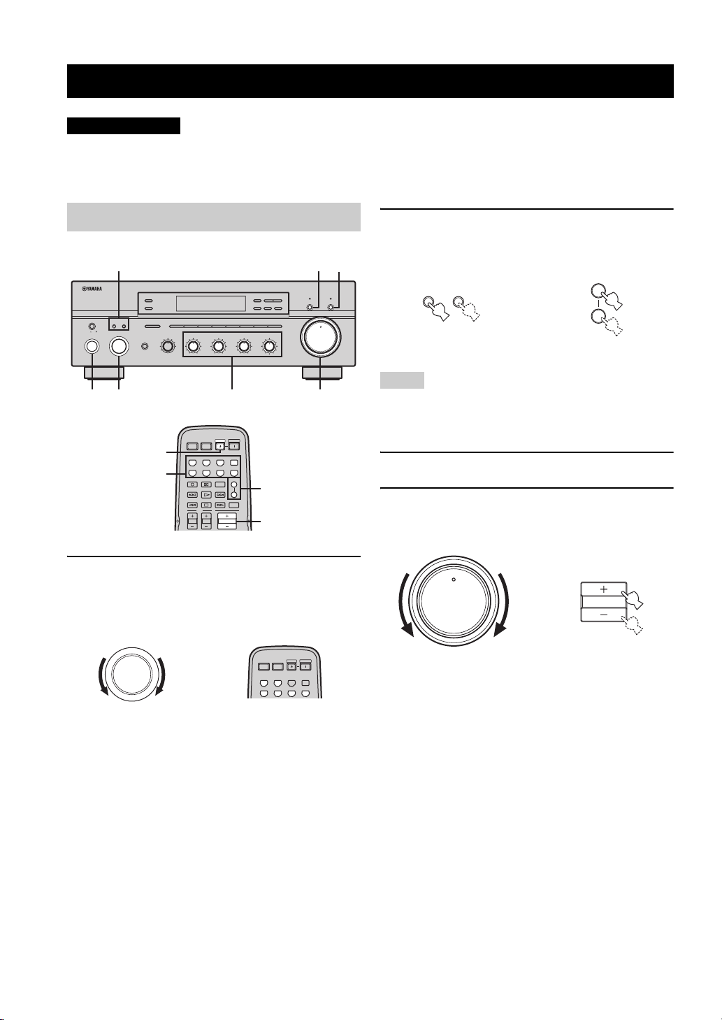
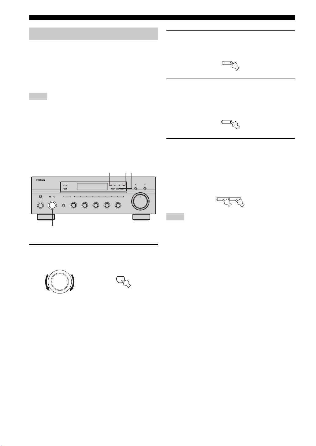
1 Rotate the INPUT selector on the front panel
(or press one of the input selector buttons on
the remote control) to select the desired
input source.
INPUT
POWER POWER
STANDBY
or
AVTV
CD
MD/TAPE
TUNER
DTV/CBL
VCR
5
CD DIRECT AMPPURE DIRECT
16
20
12
VOLUME
26
8
40
4
2
60
0
∞
-dB
4
POWER
XM
PHONODVD
2 Press SPEAKERS A and/or SPEAKERS B on
the front panel or on the remote control to
select speakers A and/or speakers B.
SPEAKERS
BA
Front panel
or
SPEAKERS
A
B
Remote control
Notes
• Both SPEAKERS A and B can be selected.
• Make sure that the IMPEDANCE SELECTOR switch is
correctly set (see page 16).
3 Play the source.
4 Rotate VOLUME on the front panel (or press
VOLUME +/– on the remote control) to adjust
the sound output level.
16
20
VOLUME
26
40
60
Front panel
12
8
4
2
∞
0
-dB
or
VOLU ME
Remote control
Front panel Remote control
18
Page 23

5 Adjust the tonal quality by using the BASS,
TREBLE, BALANCE and LOUDNESS controls
or the CD DIRECT AMP and the PURE
DIRECT buttons on the front panel.
BASS
101
22
3
44
55
–
22
3
3
44
+
TREBLE
101
55
–
22
3
3
44
+
BALANCE
101
55
L
LOUDNESS
210
3
3
48
R
FLAT
1
–
57
6
30dB
9
PLAYING AND RECORDING
PURE DIRECT
CD DIRECT AMP
6 Press MAIN ZONE ON/OFF on the front panel
again (or press STANDBY on the remote
control) to finish using this unit and set it to
the standby mode.
MAIN ZONE
ON/OFF
Front panel
or
STANDBY
Remote control
OPERATION
BASIC
19
English
Page 24
PLAYING AND RECORDING
12
20
60
26
40
16
-dB
Adjusting the tonal quality
■ Adjusting the BALANCE control
Adjusts the sound output balance of the left and right
speakers to compensate for sound imbalance caused by
speaker locations or listening room conditions.
BALANCE
101
22
3
■ Using the CD DIRECT AMP button
Routes input signals from your CD player directly to the
specially built-in amplifier for the CD player. As a result,
the input signals bypass the INPUT selector and the
BASS, TREBLE, BALANCE and LOUDNESS controls
and then sent to the power amplifier, thus eliminating any
alterations to the CD signals and creating the purest
possible sound. The CD DIRECT AMP indicator lights up
and the front panel display turns off after a few seconds.
■ Using the PURE DIRECT button
Routes input signals from your audio sources so that the
input signals bypass the BASS, TREBLE, BALANCE and
LOUDNESS controls, thus eliminating any alterations to
the audio signals and creating the purest possible sound.
3
44
55
R
L
CD DIRECT AMP
PURE DIRECT
■ Adjusting the LOUDNESS control
Retains a full tonal range at any volume level, thus
compensating for the human ears’ loss of sensitivity to
high and low-frequency ranges at a low volume level.
CAUTION
If the CD DIRECT AMP or the PURE DIRECT button is turned
on with the LOUDNESS control set at a certain level, the input
signals bypass the LOUDNESS control, resulting in a sudden
increase in the sound output level. To prevent your ears or the
speakers from being undesirably damaged, be sure to press the
CD DIRECT AMP or the PURE DIRECT button after lowering
the sound output level or after checking that the LOUDNESS
control is properly set.
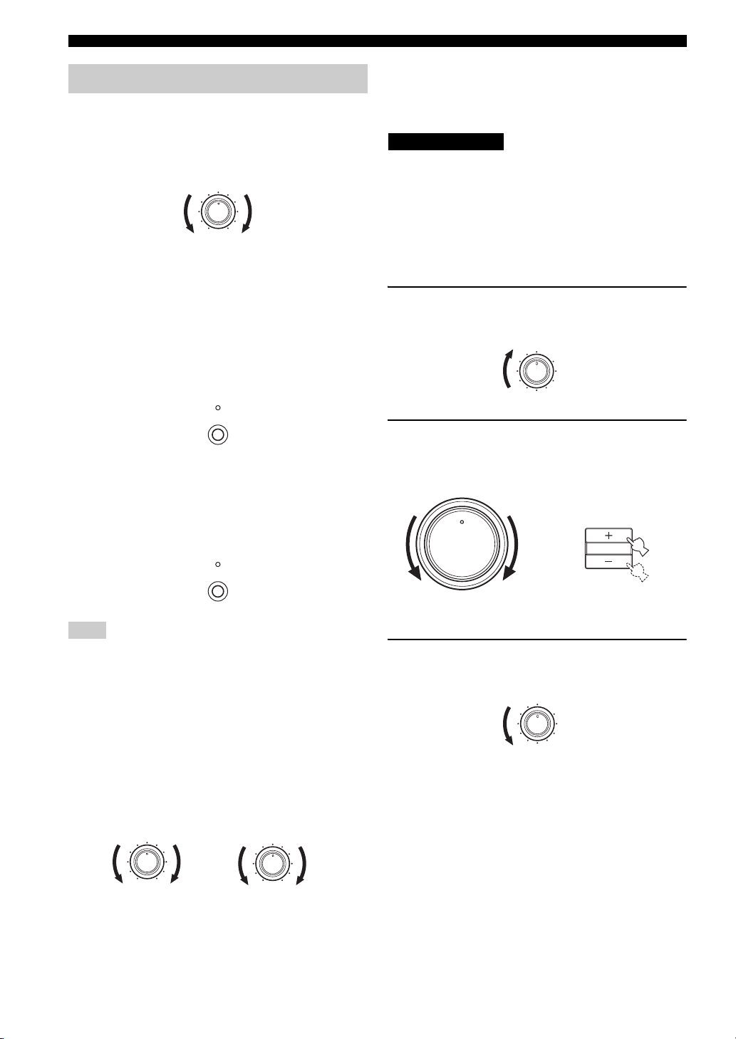
1 Rotate the LOUDNESS control on the front
panel to the FLAT position.
LOUDNESS
FLAT
1
–
30dB
210
3
9
48
57
6
2 Rotate VOLUME on the front panel (or press
VOLUME +/– on the remote control) to set the
sound output level to the loudest listening
level that you would listen to.
16
20
VOLUME
26
40
60
Front panel
12
8
4
or
2
0
∞
-dB
VOLU ME
Remote control
Note
If both the CD DIRECT AMP and the PURE DIRECT buttons
are turned on, only the CD DIRECT AMP button will function.
■ Adjusting the BASS and TREBLE
controls
Adjust the high and low frequency response.
BASS
3 Rotate the LOUDNESS control until the
desired volume is obtained.
LOUDNESS
FLAT
1
–
30dB
210
3
9
48
57
6
Increases or decreases the low frequency response.
TREBLE
Increases or decreases the high frequency response.
BASS
101
22
3
20
3
44
55
+
–
TREBLE
101
22
3
3
44
55
+
–
Page 25
PLAYING AND RECORDING
12
20
60
26
40
16
-dB
12
20
60
26
40
16
-dB
Recording a source
Notes
• The VOLUME, BASS, TREBLE, BALANCE and
LOUDNESS controls and the CD DIRECT AMP and the PURE
DIRECT buttons have no effect on the source being recorded.
• Check the copyright laws in your country to record from
records, CDs, radio, etc. Recording copyright-protected
material may infringe on copyright laws.
l
TUNING/CH
ZONE 2 ON/OFF
ZONE CONTROL
MASTER SPEAKERS
BA
A/B/C/D/E
12345678
ON OFF
MAIN ZONE
ON/OFF
CATEGORY
INPUT
PHONES
MD/TAPECDXM
VCR TUNER
DTV/CBL
DVD
BASS
22
PHONO
3
44
101
55
–
3
+
TREBLE
101
22
3
3
44
55
+
–
3
REC OUT
3
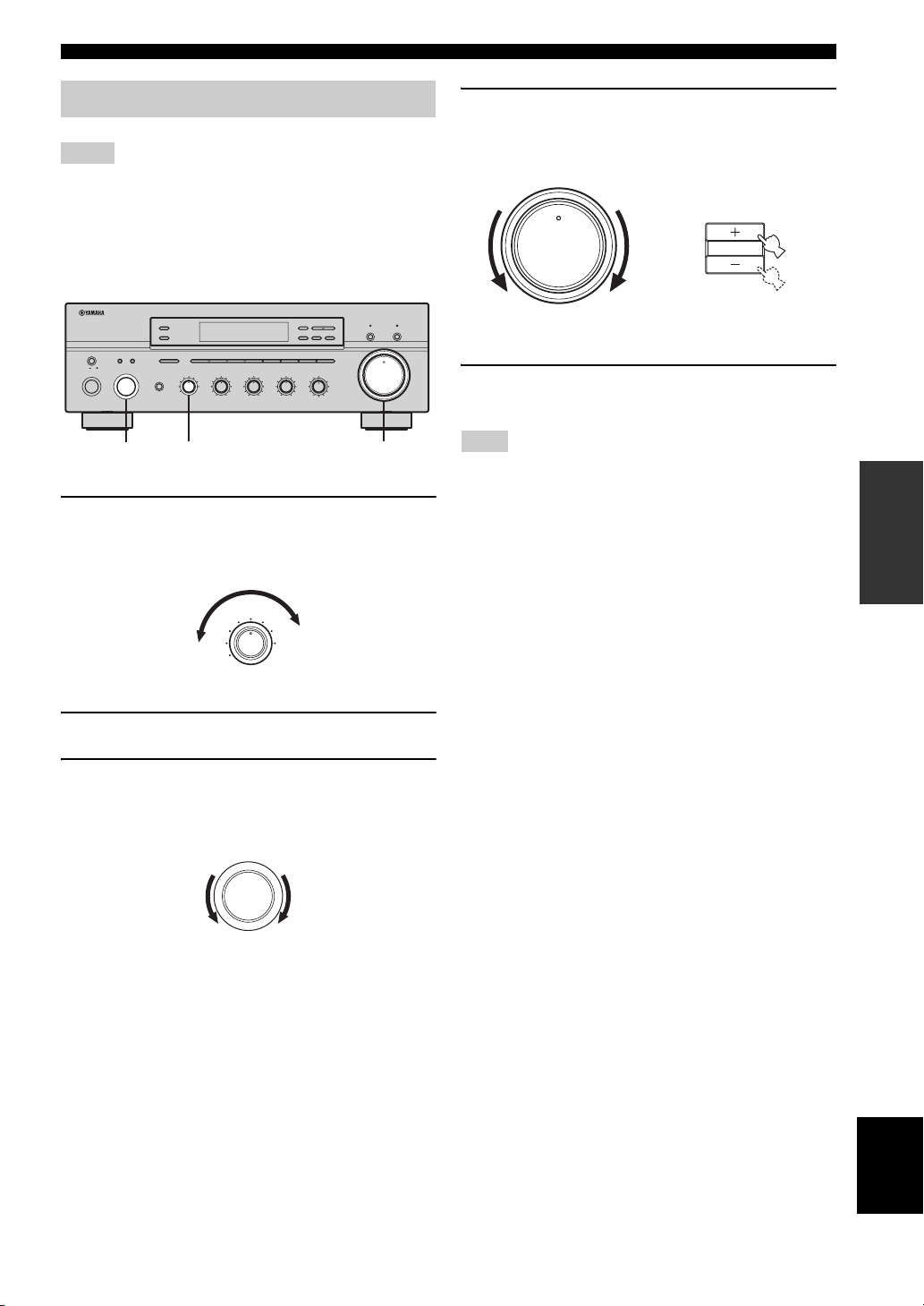
1 Rotate the REC OUT selector on the front
panel to select the source you want to record
from.
REC OUT
MD/TAPECDXM
VCR TUNER
DTV/CBL
DVD
FM/AM
XM/ANT
EDIT
SEARCH MODE
BALANCE
101
22
3
44
55
R
L
PHONO
MEMORY
TUN MODE/DISP
MAN'L/AUTO FM
AUTO/MAN'L
LOUDNESS
FLAT
1
–
30dB
210
3
48
57
6
h
9
CD DIRECT AMPPURE DIRECT
16
20
12
VOLUME
26
40
60
0
∞
-dB
41
4 Rotate VOLUME on the front panel (or press
VOLUME +/– on the remote control) to adjust
the sound output level of the selected source
to record from.
16
20
VOLUME
26
40
60
Front panel
8
4
2
5 Begin recording on the MD recorder, the tape
deck or the VCR connected to this unit.
Note
Selecting another source with the INPUT selector on the front
panel (or the corresponding input selector button on the remote
control) while recording is in progress will not affect the
recording.
y
You can monitor the sound and/or picture being recorded by
rotating the INPUT selector on the front panel (or pressing MD/
TAPE or VCR on the remote control) to select the MD recorder,
the tape deck or the VCR used for recording.
12
8
or
4
2
0
∞
-dB
VOLUME
Remote control
OPERATION
BASIC
2 Play the selected source to record from.
3 Rotate the INPUT selector on the front panel
to confirm the selected source to record
from.
INPUT
English
21
Page 26
PLAYING AND RECORDING
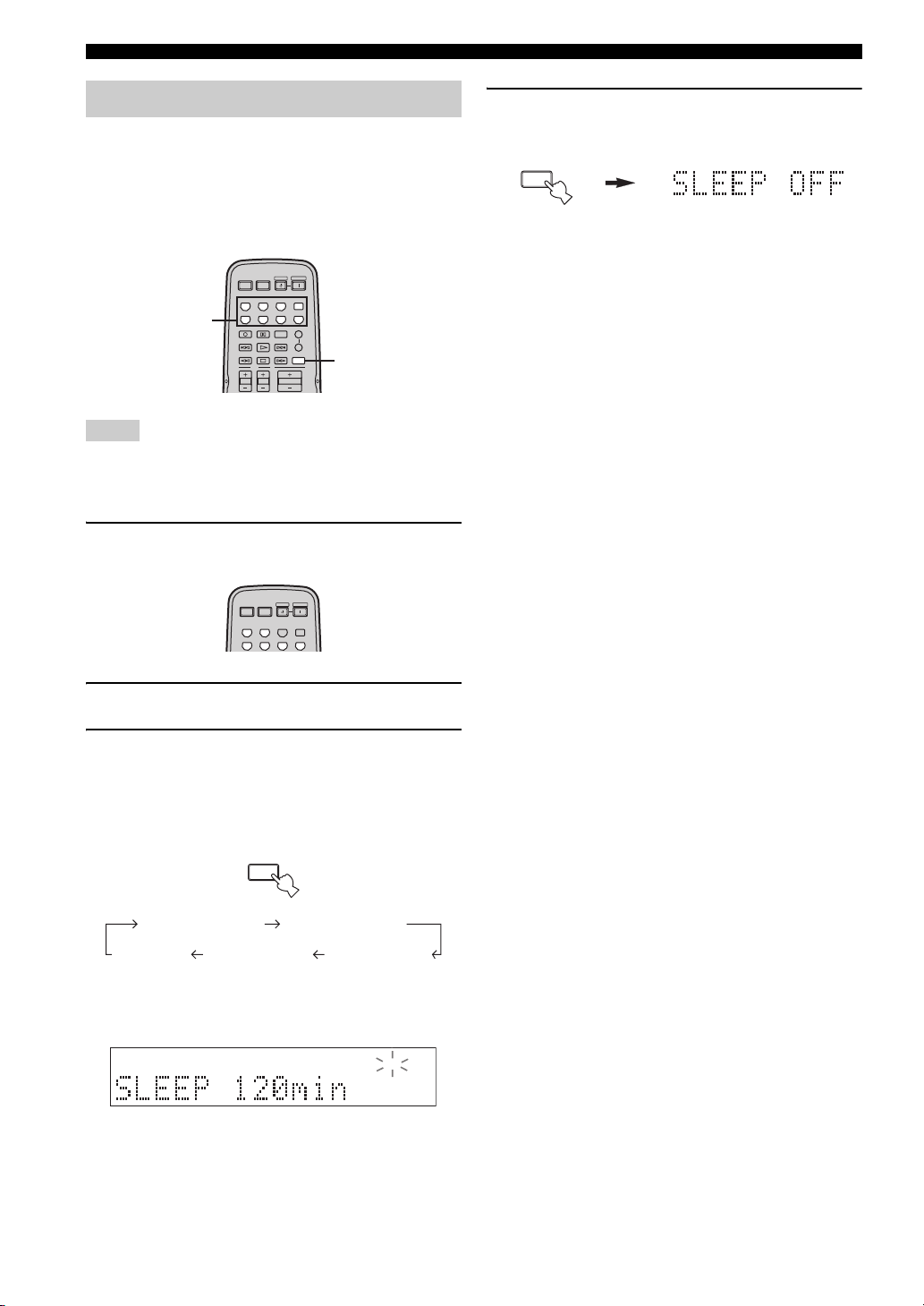
Using the sleep timer
Use this feature to automatically set this unit to the
standby mode after a certain amount of time. The sleep
timer is useful when you are going to sleep while this unit
is playing or recording a source. The sleep timer also
automatically turns off any external components
connected to the AC OUTLET(S).
POWER POWER
STANDBY
POWER
AVTV
CD
MD/TAPE
TUNER
XM
PHONODVD
DTV/CBL
REC
DISC SKIP
TV
VOL CH
POWER POWER
CD
MD/TAPE
DTV/CBL
VCR
CODE SET
SPEAKERS
A
B
SLEEP
VOLUME
STANDBY
AVTV
TUNER
VCR
3
POWER
XM
PHONODVD
1
Notes
• The sleep timer can only be set with the remote control.
• The sleep timer automatically turns off Zone 2. However, the
power of Zone 2 components are not turned off.
1 Press one of the input selector buttons on
the remote control to select an input source.
4 Press SLEEP repeatedly so that SLEEP OFF
appears in the front panel display.
SLEEP
After a few seconds, SLEEP OFF disappears from the
front panel display, and the SLEEP indicator turns
off.
y
The sleep timer setting can also be canceled by pressing
STANDBY on the remote control (or MAIN ZONE ON/OFF or
MASTER ON/OFF on the front panel) to set this unit to the
standby mode.
2 Start playback on the selected input source.
3 Press SLEEP repeatedly to set the amount of
time before this unit is set to the standby
mode.
Each time you press SLEEP, the front panel display
changes as shown below.
SLEEP
SLEEP 120 min SLEEP 90 min
SLEEP 60 minSLEEP 30 minSLEEP OFF
The SLEEP indicator flashes while switching the
amount of time for the sleep timer.
SLEEP
22
Page 27
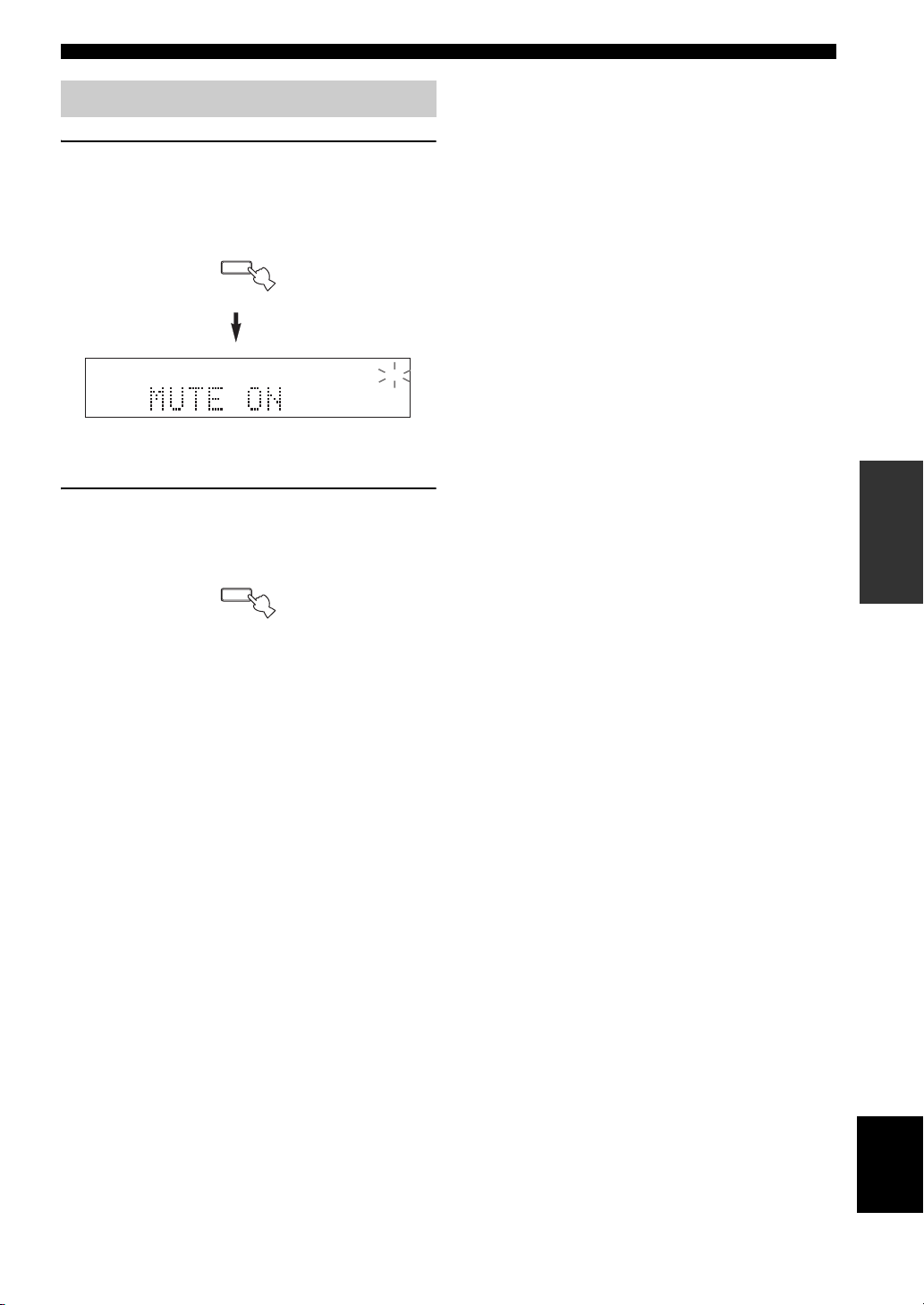
Muting the sound output
1 Press MUTE on the remote control to mute
the sound output.
The MUTE indicator flashes in the front panel
display and MUTE ON appears in the front panel
display.
MUTE
MUTE
After a few seconds, MUTE ON disappears from the
front panel display.
2 Press MUTE on the remote control again to
resume the sound output.
The MUTE indicator disappears from the front panel
display.
MUTE
PLAYING AND RECORDING
OPERATION
BASIC
23
English
Page 28
FM/AM TUNING
12
20
60
26
40
16
-dB
FM/AM TUNING
There are 2 tuning methods; automatic and manual. Select either method according to your preference and the strength of
station signals.
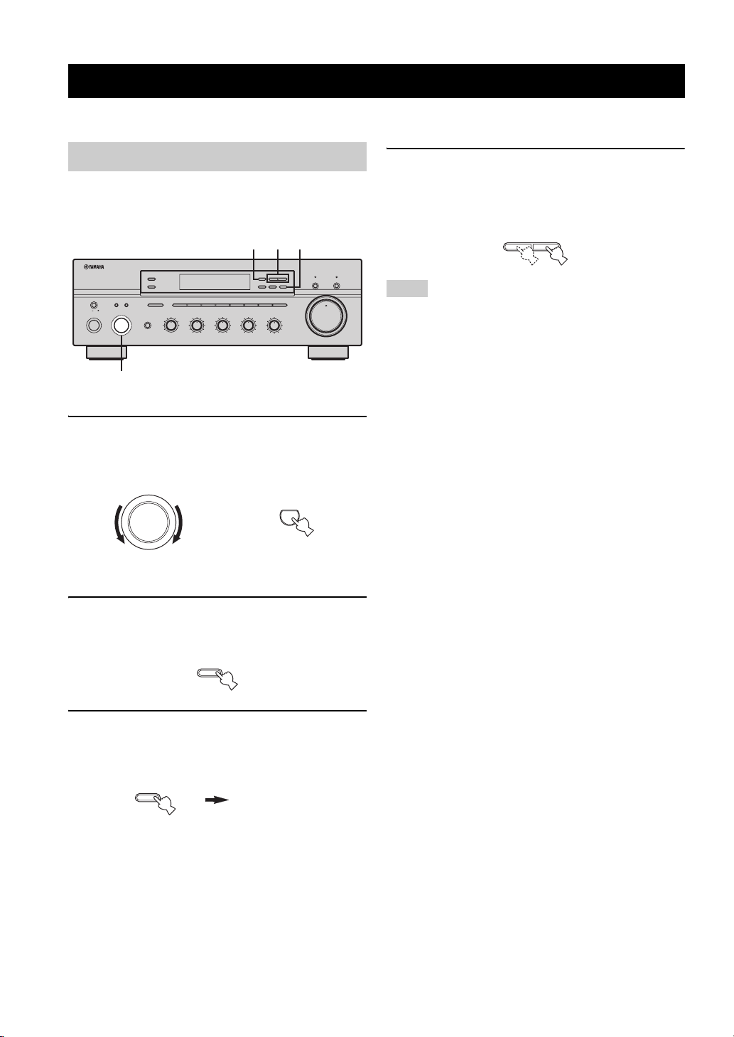
Automatic tuning
Automatic tuning is effective when station signals are
strong and there is no interference.
2 4 3
l TUNING/CH
BALANCE
101
55
L
FM/AM
XM/ANT
EDIT
SEARCH MODE
3
R
h
MEMORY
TUN MODE/DISP
MAN'L/AUTO FM
AUTO/MAN'L
LOUDNESS
FLAT
1
–
30dB
210
3
9
48
57
6
TUNER
CD DIRECT AMPPURE DIRECT
16
20
12
VOLUME
26
8
40
4
2
60
0
∞
-dB
ZONE 2 ON/OFF
ZONE CONTROL
MASTER SPEAKERS
BA
A/B/C/D/E
12345678
ON OFF
MAIN ZONE
ON/OFF
CATEGORY
INPUT
PHONES
MD/TAPECDXM
VCR TUNER
DTV/CBL
DVD
BASS
22
PHONO
3
44
–
101
55
3
+
TREBLE
101
22
3
44
55
+
–
22
3
3
44
REC OUT
1
1 Rotate the INPUT selector (or press TUNER
on the remote control) to select TUNER as
the input source.
INPUT
or
Front panel Remote control
4 Press TUNING/CH l / h once to begin
automatic tuning.
Press h to tune into a higher frequency.
Press l to tune into a lower frequency.
l
TUNING/CH
h
Notes
• When you tune into a station, the frequency of the received
station is shown in the front panel display.
• To search for another station, press TUNING/CH l / h once
more.
• If the tuning search does not stop at the desired station because
the station signals are weak, try using the manual tuning
method.
2 Press FM/AM on the front panel to select the
reception band (FM or AM).
FM or AM appears in the front panel display.
FM/AM
XM/ANT
3 Press TUN MODE on the front panel so that
the AUTO indicator lights up in the front
panel display.
TUN MODE/DISP
AUTO/MAN'L
AUTO
Lights up
24
Page 29
FM/AM TUNING
12
20
60
26
40
16
-dB
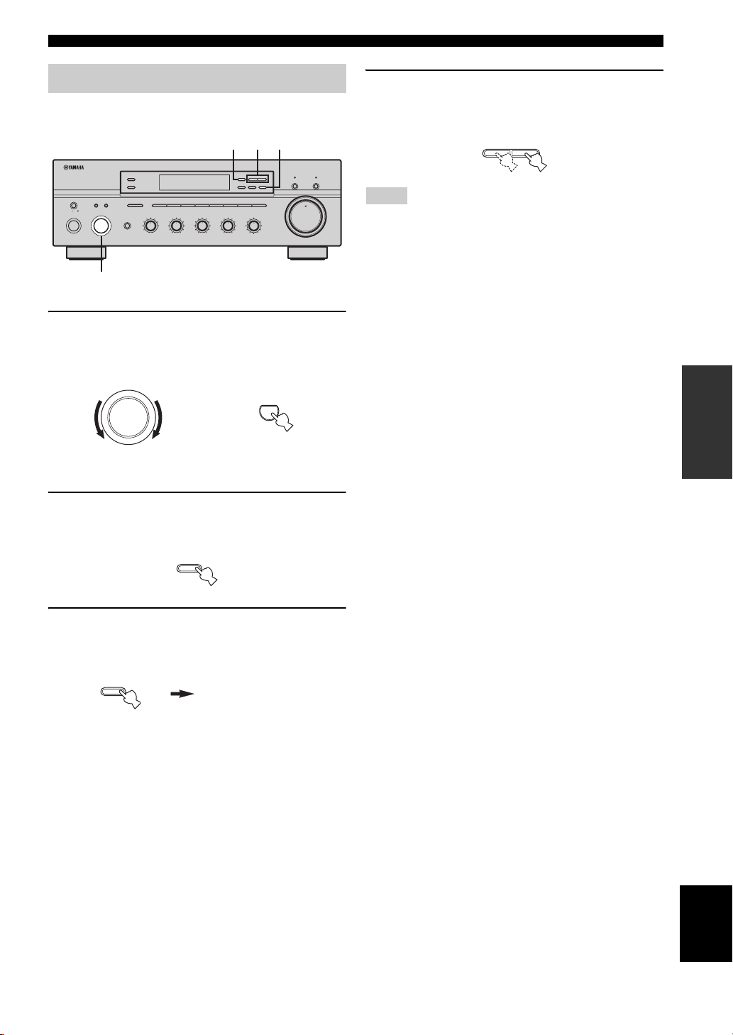
Manual tuning
Manual tuning is effective when station signals are weak.
2 4 3
l
TUNING/CH
ZONE 2 ON/OFF
ZONE CONTROL
MASTER SPEAKERS
BA
A/B/C/D/E
12345678
ON OFF
MAIN ZONE
ON/OFF
CATEGORY
INPUT
REC OUT
MD/TAPECDXM
PHONES
VCR TUNER
DTV/CBL
DVD
22
PHONO
3
44
BASS
101
55
–
3
+
TREBLE
101
22
3
3
44
55
+
–
22
3
44
1
1 Rotate the INPUT selector (or press TUNER
on the remote control) to select TUNER as
the input source.
INPUT
or
Front panel
h
FM/AM
XM/ANT
EDIT
MEMORY
TUN MODE/DISP
SEARCH MODE
MAN'L/AUTO FM
AUTO/MAN'L
BALANCE
LOUDNESS
FLAT
101
1
–
30dB
210
3
3
9
48
55
R
L
57
6
TUNER
Remote control
CD DIRECT AMPPURE DIRECT
16
20
12
VOLUME
26
8
40
4
2
60
0
∞
-dB
4 Press TUNING/CH l / h to manually tune
into the desired station.
Hold down the button to continue tuning search.
l
TUNING/CH
h
Notes
• When you tune into a station, the frequency of the received
station is shown in the front panel display.
• If you tune into an FM station, it is automatically received in the
monaural mode to increase signal quality.
OPERATION
BASIC
2 Press FM/AM on the front panel to select the
reception band (FM or AM).
FM or AM appears in the front panel display.
FM/AM
XM/ANT
3 Press TUN MODE on the front panel so that
the AUTO indicator disappears from the front
panel display.
TUN MODE/DISP
AUTO/MAN'L
AUTO
Disappears
English
25
Page 30
FM/AM TUNING
12
20
60
26
40
16
-dB
Automatic preset tuning
You can use the automatic preset tuning method to
automatically store FM stations. This function enables this
unit to automatically tune into FM stations with strong
signals and store up to 40 (8 stations in each of the 5
groups, A1 to E8) of those received stations in order. You
can then easily recall any preset stations by selecting the
preset station numbers where they are stored.
Notes
• Any station data stored under a preset station number is cleared
when you store a new station under that preset station number.
• If the number of received stations does not reach 40 (E8),
automatic preset tuning automatically stops once searching all
available stations are tuned into and stored.
• Only FM stations with sufficient signal strength are stored
automatically by automatic preset tuning. If the station you
want to store is weak in signal strength, try using the manual
preset tuning method.
l
TUNING/CH
EDIT
MEMORY
MAN'L/AUTO FM
LOUDNESS
FLAT
1
210
3
48
57
6
TUNER
4
3
h
TUN MODE/DISP
AUTO/MAN'L
–
30dB
9
CD DIRECT AMPPURE DIRECT
16
20
12
VOLUME
26
8
40
4
2
60
0
∞
-dB
2
MASTER SPEAKERS
ON OFF
MAIN ZONE
ON/OFF
ZONE 2 ON/OFF
ZONE CONTROL
BA
A/B/C/D/E
12345678
CATEGORY
INPUT
REC OUT
BASS
MD/TAPECDXM
VCR TUNER
DTV/CBL
DVD
22
PHONO
3
44
–
101
55
3
+
22
3
44
–
PHONES
TREBLE
101
55
3
+
BALANCE
101
22
3
44
55
R
L
FM/AM
XM/ANT
SEARCH MODE
3
1
1 Rotate the INPUT selector (or press TUNER
on the remote control) to select TUNER.
INPUT
or
2 Press FM/AM on the front panel to select FM
as the reception band.
FM appears in the front panel display.
FM/AM
XM/ANT
3 Press and hold MEMORY on the front panel
for more than 3 seconds.
The preset station group and the MEMORY and
AUTO indicators flash in the front panel display.
MEMORY
MAN'L/AUTO FM
4 Press TUNING/CH l / h once to begin
automatic preset tuning.
Press h to tune into higher frequencies.
Press l to tune into lower frequencies.
When automatic preset tuning is complete, the
frequency of the last preset station is shown in the
front panel display.
l
TUNING/CH
h
Notes
• If TUNING/CH l / h is not pressed within approximately 5
seconds while the MEMORY and AUTO indicators are
flashing, automatic preset tuning automatically begins from the
currently displayed frequency and proceeds toward higher
frequencies.
• Received stations are sequentially programmed to 8 stations in
each preset station group. If 8 stations are all programmed in a
preset station group, another 8 stations are sequentially
programmed in the next preset station group.
Front panel Remote control
26
Page 31

■ Customized automatic preset tuning
You can specify a preset station group and a preset station
number from which this unit stores the FM stations
received by automatic preset tuning.
1 Press and hold MEMORY on the front panel
for more than 3 seconds.
MEMORY
MAN'L/AUTO FM
FM/AM TUNING
3 Press TUNING/CH l / h on the front panel to
begin automatic preset tuning.
Press h to tune into higher frequencies.
Press l to tune into lower frequencies.
When automatic preset tuning is complete, the
frequency of the last preset station is shown in the
front panel display.
l
TUNING/CH
h
2 Press A/B/C/D/E and then press one of the
preset station/channel number buttons on
the front panel to select the preset station
group and the preset station number where
the first received station will be stored.
For example, if you select C5, the first received
station is automatically programmed to C5 and the
next received stations are sequentially programmed
to C6, C7, etc.
A/B/C/D/E
CATEGORY
12345678
Note
Automatic preset tuning stops when the received stations have all
been stored up to E8.
OPERATION
BASIC
27
English
Page 32

FM/AM TUNING
12
20
60
26
40
16
-dB
Manual preset tuning
You can also manually store up to 40 stations (8 stations in
each of the 5 groups, A1 to E8). You can then easily recall
any preset stations by selecting the preset station numbers
where they are stored.
2
l
TUNING/CH
BALANCE
101
55
L
FM/AM
XM/ANT
EDIT
SEARCH MODE
3
R
MEMORY
MAN'L/AUTO FM
LOUDNESS
FLAT
1
210
3
48
57
h
TUN MODE/DISP
AUTO/MAN'L
VOLUME
26
40
–
30dB
9
60
6
MEMORY
Flashes
CD DIRECT AMPPURE DIRECT
16
20
12
8
4
2
0
∞
-dB
ZONE 2 ON/OFF
ZONE CONTROL
MASTER SPEAKERS
BA
A/B/C/D/E
12345678
ON OFF
MAIN ZONE
ON/OFF
CATEGORY
INPUT
REC OUT
MD/TAPECDXM
PHONES
VCR TUNER
DTV/CBL
DVD
3
22
PHONO
3
44
–
BASS
101
55
3
+
TREBLE
101
22
3
44
55
+
–
22
3
3
44
4
1 Repeat steps 1 to 4 in “Automatic tuning” or
in “Manual tuning” to tune into a station.
When you tune into a station, the frequency of the
received station is shown in the front panel display.
2 Press MEMORY on the front panel.
The MEMORY indicator flashes in the front panel
display for approximately 5 seconds.
MEMORY
MAN'L/AUTO FM
4 Press one of the preset station/channel
number buttons on the front panel to select a
preset station number (1 to 8) where you
want to store the station.
12345678
Note
This operation must be done within 5 seconds while the
MEMORY indicator is flashing in the front panel display.
Otherwise, the manual preset tuning process is automatically
canceled.
5 Press MEMORY on the front panel to store
the station.
6 Repeat steps 1 to 5 to store other stations.
Notes
• Any station data stored under a preset station number is cleared
when you store a new station under that preset station number.
• The reception mode (stereo or monaural) is stored along with
the station frequency.
3 Press A/B/C/D/E on the front panel
repeatedly to select a preset station group (A
to E).
The selected preset station group is shown in the front
panel display.
A/B/C/D/E
CATEGORY
28
Page 33

FM/AM TUNING
12
20
60
26
40
16
-dB
12
20
60
26
40
16
-dB
Selecting preset stations
You can tune into the desired station simply by selecting
the preset station number where it is stored.
l
TUNING/CH
ZONE 2 ON/OFF
ZONE CONTROL
MASTER SPEAKERS
BA
A/B/C/D/E
12345678
ON OFF
MAIN ZONE
ON/OFF
CATEGORY
INPUT
PHONES
1
MD/TAPECDXM
VCR TUNER
DTV/CBL
DVD
BASS
22
PHONO
3
44
101
55
–
3
+
TREBLE
101
22
3
3
44
55
+
–
22
3
44
REC OUT
2
1 Press A/B/C/D/E on the front panel
repeatedly (or press A-E/CAT. j / i on the
remote control) to select a preset station
group (A to E).
The selected preset station group is shown in the front
panel display.
A/B/C/D/E
CATEGORY
Front panel
or
A-E/CAT. A-E/CAT.
2 Press one of the preset station/channel
number buttons on the front panel (or
PRESET/CH u / d on the remote control) to
select a preset station number (1 to 8).
The preset station number appears in the front panel
display along with the reception band and the
frequency.
12345678
Front panel
or
h
FM/AM
XM/ANT
EDIT
MEMORY
TUN MODE/DISP
SEARCH MODE
MAN'L/AUTO FM
AUTO/MAN'L
210
3
3
48
LOUDNESS
1
57
VOLUME
FLAT
–
30dB
9
6
BALANCE
101
55
L
R
ENTER
PRESET/CH
Remote control
CD DIRECT AMPPURE DIRECT
16
20
12
26
8
40
4
2
60
0
∞
-dB
Exchanging preset stations
You can exchange the assignment of two preset stations
with each other. The following procedure describes an
example where a preset station E1 is exchanged with
another preset station A5.
2,4
l
TUNING/CH
ZONE 2 ON/OFF
ZONE CONTROL
MASTER SPEAKERS
BA
A/B/C/D/E
12345678
ON OFF
MAIN ZONE
ON/OFF
CATEGORY
INPUT
PHONES
MD/TAPECDXM
VCR TUNER
DTV/CBL
DVD
BASS
22
PHONO
3
44
–
101
55
3
+
TREBLE
101
22
3
3
44
55
+
–
3
REC OUT
1 Repeat steps 1 and 2 in “Selecting preset
stations” to select a preset station E1.
2 Press EDIT on the front panel.
E1 and the MEMORY indicator flash in the front
panel display.
EDIT
SEARCH MODE
3 Repeat steps 1 and 2 in “Selecting preset
stations” to select another preset station A5.
A5 and the MEMORY indicator flash in the front
panel display.
MEMORY
Flashes
4 Press EDIT on the front panel again.
E1-A5 appears in the front panel display, indicating
that the two preset station assignments have been
exchanged.
EDIT
SEARCH MODE
FM/AM
XM/ANT
SEARCH MODE
BALANCE
101
22
3
44
55
R
L
h
EDIT
MEMORY
TUN MODE/DISP
MAN'L/AUTO FM
AUTO/MAN'L
LOUDNESS
FLAT
1
–
30dB
210
3
9
48
57
6
MEMORY
Flashes
CD DIRECT AMPPURE DIRECT
16
20
12
VOLUME
26
8
40
2
60
0
∞
-dB
4
OPERATION
BASIC
ENTER
A-E/CAT. A-E/CAT.
PRESET/CH
Remote control
English
29
Page 34

XM SATELLITE RADIO TUNING
A
B
(
T
XM SATELLITE RADIO TUNING
What is XM Satellite Radio?
XM Satellite Radio is the satellite radio service with
millions of listeners across the United States broadcasting
live daily. The XM Satellite Radio channel lineup includes
more than 150 digital channels of choice from coast to
coast: 67 commercial-free music channels, featuring hip
hop to opera, classical to country, bluegrass to blues; 64
channels of premier sports, talk, comedy, children’s and
entertainment programming; and more than 26 channels
of the traffic and weather information for major
metropolitan areas nationwide.
Because XM Satellite Radio is a subscription service, you
will need to set up an account and activate service with
XM using your XM Satellite Radio ID number. To check
your ID number, follow “Activating XM Satellite Radio”
on page 33. For further information on XM Satellite Radio
services, visit the XM Satellite Radio website at
“http://www.xmradio.com”.
Notes
• The XM Satellite Radio service is only available in the 48
contiguous United States (not available in Alaska and Hawaii).
• XM Connect-and-Play digital antenna accessory and monthly
subscription are sold separately. For details, visit the XM
Satellite Radio website at “http://www.xmradio.com”.
XM Satellite Radio connections
Connect the XM Connect-and-Play digital antenna
accessory (sold separately) to the XM jack on the rear of
this unit. (For details, refer to the operating instructions
provided with the XM Connect-and-Play digital antenna
accessory.)
XM jack
DVD
IN
DTV/
OUT
CBL
IN
IN
CONTROL OUT
+12V 15mA MAX.
VCR
COUPLER
OUT
IN
PLAY)
MD/
APE
OUT
REC)
SUB
WOOFER
ONE 2
OUT
OUTPUT
Notes
• For information on obtaining the XM Connect-and-Play digital
antenna accessory, visit the XM Satellite Radio website at
“http://www.xmradio.com” or consult your local retailer that
sells XM Ready products.
• To ensure the optimal reception of the XM Satellite Radio
signals, the XM Connect-and-Play digital antenna accessory
must be placed at or near a southerly facing window with no
obstacles in the path to the sky. You can mount it indoors or
outdoors.
XMREMOTE
1
2
SPEAKERS
MAIN
IN
PRE
OUT
CLASS 2 WIRING
Information from XM Satellite Radio, Inc.
Hardware and required basic monthly subscription sold
separately. Premium Channel available at additional monthly
cost. Installation costs and other fees and taxes, including a onetime activation fee may apply. Subscription fee is consumer
only. All fees and programming subject to change.
Subscriptions subject to Customer Agreement available at
xmradio.com. Only available in the 48 contiguous United
States.
© 2005 XM Satellite Radio Inc. All rights reserved. All other
trademarks are the property of their respective owners.
30
Page 35

XM Satellite Radio functions
12
20
60
26
40
16
-dB
This section describes the functions of each control used
for the XM Satellite Radio tuning.
Note
The following controls on the front panel and the remote controls
are only available when
the XM Connect-and-Play digital antenna accessory is connected
XM jack on the rear panel of this unit (see “XM Satellite
to the
Radio connections”).
■ Controls on the front panel
MASTER SPEAKERS
BA
ON OFF
INPUT
MAIN ZONE
ON/OFF
1 SEARCH MODE
Switches between the All Channel Search, Category
Search, and Preset Search modes (see page 35).
2 XM ANT (ANTENNA)
Shows the reception level of the XM Connect-and-Play
digital antenna (sold separately).
XM is selected as the input source and
134
2
3
+
BALANCE
101
22
3
3
44
55
R
L
l TUNING/CH
FM/AM
XM/ANT
EDIT
MEMORY
SEARCH MODE
MAN'L/AUTO FM
LOUDNESS
1
210
3
48
57
FLAT
6
ZONE 2 ON/OFF
ZONE CONTROL
A/B/C/D/E
12345678
CATEGORY
REC OUT
MD/TAPECDXM
PHONES
VCR TUNER
DTV/CBL
PHONO
DVD
BASS
101
22
3
3
44
55
+
–
TREBLE
101
22
3
44
55
–
6 75
h
TUN MODE/DISP
AUTO/MAN'L
–
30dB
9
CD DIRECT AMPPURE DIRECT
16
20
12
VOLUME
26
8
40
4
2
60
0
∞
-dB
8
XM SATELLITE RADIO TUNING
5 INPUT selector
Selects XM as the input source.
6 CATEGORY
All Channel Search mode
Switches between channel categories while staying in
the All Channel Search mode.
Category Search mode
Switches between channel categories.
Preset Search mode
Selects the preset channel group (A to E).
7 Preset channel number buttons
Selects the preset channel number (1 to 8) directly.
Pressing these buttons switches the search mode to the
Preset Search mode.
8 MEMORY
Stores a radio channel in the system memory.
OPERATION
BASIC
3 TUNING/CH l / h
All Channel Search mode
Searches for a radio channel within all channels.
Press and hold for quick search.
Category Search mode
Searches for a radio channel within the selected
category. Press and hold for quick search.
Preset Search mode
Selects the preset channel number (1 to 8).
4 DISP (DISPLAY)
Switches the XM Satellite Radio information shown in the
front panel display between channel number/name,
category and artist name/song title (see page 34).
English
31
Page 36

XM SATELLITE RADIO TUNING
■ Controls on the remote controls
SYSTEM
MD/TAPE
DTV/CBL
AVTV
ENTER
PRESET/CH
STANDBY
TUNER
CODE SET
VCR
VOLUME
MUTE
POWER
PHONODVD
SPEAKERS
SLEEP
MENUTITLE
SRCH MODE
DISPLAYRETURN
XM
4
ZONE 2
CD1PHONO
DVD7XM
PRESET
A/B/C/D/E
lA-E/CAT.
w
ALL
b
u
d
2
8 9
k
e
PRESET/CH
s
n
NUMBER
p
TUNER
VOLUME
A-E/CAT.h
f
PRESET
a
3
6
+
–
MUTE
A
B
4321
81070965
ENT.
5
6
8
2
9
MD/TAPE4VCR5DTV/CBL
7
0
POWER POWER
CD
REC
DISC SKIP
TV
VOL CH
MUTE INPUT
1
BAND
2
3
A-E/CAT. A-E/CAT.
MEMORY
1 Numeric buttons
All Channel Search or Category Search mode
Use 1 to 9 and 0 to enter a channel number directly.
Preset Search mode
Use 1 to 8 to enter a preset channel number directly.
2 A-E/CAT. (CATEGORY) j / i (l / h)
All Channel Search mode
Switches between channel categories while staying in
the All Channel Search mode.
Category Search mode
Switches between channel categories.
Preset Search mode
Selects the preset channel group (A to E).
PRESET/CH u / d (k / n)
All Channel Search mode
Searches for a radio channel within all channels. Press
and hold for quick search.
Category Search mode
Searches for a radio channel within the selected
category. Press and hold for quick search.
Preset Search mode
Selects the preset channel number (1 to 8).
POWER
STANDBY
DISPLAY
CAT.
DISC
5 ENT. (ENT) (ENTER)
Confirms an entered channel number when this unit is in
the Direct Number Access mode (see page 37).
6 SRCH (SEARCH) MODE
Switches between the All Channel Search, Category
Search, and Preset Search modes (see page 35).
7 DISPLAY
ENT
0
0
Switches XM information such as channel number/name,
5
category, or artist name/song title displayed in the front
panel display and on-screen display (see page 34).
8 Input selector/numeric buttons
All Channel Search or Category Search mode
7
A
B
XMCDID2ID1
C
Use 1 to 9 and 0 to enter a channel number directly.
Also refer to 0 NUMBER.
Preset Search mode
Use 1 to 8 to enter a preset channel number directly.
Also refer to 0 NUMBER.
Note
You must press and hold 0 NUMBER before you press any of
these buttons to enter numbers.
9 ALL
Selects the All Channel Search mode.
0 NUMBER
Press and hold before you press the input selector/numeric
buttons to switch the function to enter numbers.
A CAT. (CATEGORY)
Selects the Category Search mode.
B PRESET
Selects the Preset Search mode.
C CD/XM switch
Switches the function of the control buttons on the Zone 2
remote control numbered 2, 7, 9, 0, A and B
between controlling YAMAHA CD players and
controlling the XM Satellite Radio features.
3 MEMORY
Stores a radio channel in the system memory.
4 XM
Selects XM as the input source.
32
Page 37

XM SATELLITE RADIO TUNING
12
20
60
26
40
16
-dB
Activating XM Satellite Radio
To sign up for an account with the XM Satellite Radio
service, an XM Satellite Radio ID number is required.
Follow the procedure below to check your ID number, and
then visit the website at “http://activate.xmradio.com” or
call “1-800-XM-RADIO (1-800-967-2346)” to sign up
with your major credit card handy.
2 3
l
TUNING/CH
ZONE 2 ON/OFF
ZONE CONTROL
MASTER SPEAKERS
BA
A/B/C/D/E
12345678
ON OFF
MAIN ZONE
ON/OFF
CATEGORY
INPUT
PHONES
MD/TAPECDXM
VCR TUNER
DTV/CBL
DVD
BASS
22
PHONO
3
44
101
55
–
3
+
TREBLE
101
22
3
3
44
55
+
–
22
3
44
REC OUT
1
1 Rotate the INPUT selector on the front panel
(or press XM on the remote control) to select
XM as the input source.
INPUT
or
Front panel
If CHECK ANTENNA appears in the front panel
display, the XM Connect-and-Play digital antenna
accessory may not be connected to the XM jack on
the rear panel of this unit properly. See “XM Satellite
Radio connections” on page 30 and check the
connection.
h
FM/AM
XM/ANT
EDIT
MEMORY
TUN MODE/DISP
SEARCH MODE
MAN'L/AUTO FM
AUTO/MAN'L
BALANCE
LOUDNESS
FLAT
101
1
–
30dB
210
3
3
9
48
55
R
L
57
6
XM
Remote control
CD DIRECT AMPPURE DIRECT
16
20
12
VOLUME
26
8
40
4
2
60
0
∞
-dB
2 Press SEARCH MODE on the front panel (or
SRCH MODE on the remote control)
repeatedly to select the All Channel Search
mode.
ALL CH SEARCH appears in the front panel display.
EDIT
SEARCH MODE
Front panel
or
MENU
SRCH MODE
Remote control
3 Press TUNING/CH l / h on the front panel
(or PRESET/CH u / d on the remote control)
to select channel 0.
l
TUNING/CH
h
Front panel
or
ENTER
A-E/CAT. A-E/CAT.
PRESET/CH
Remote control
4 Check the XM Satellite Radio ID number
shown in the front panel display and write it
down.
ID:_____________________________________
OPERATION
BASIC
English
33
Page 38

XM SATELLITE RADIO TUNING
12
20
60
26
40
16
-dB
Basic XM Satellite Radio operations
2
l
TUNING/CH
BALANCE
101
55
L
FM/AM
XM/ANT
EDIT
SEARCH MODE
3
R
h
MEMORY
TUN MODE/DISP
MAN'L/AUTO FM
AUTO/MAN'L
LOUDNESS
FLAT
1
–
30dB
210
3
9
48
57
6
XM
CD DIRECT AMPPURE DIRECT
16
20
12
VOLUME
26
8
40
4
2
60
0
∞
-dB
ZONE 2 ON/OFF
ZONE CONTROL
MASTER SPEAKERS
BA
A/B/C/D/E
12345678
ON OFF
MAIN ZONE
ON/OFF
CATEGORY
INPUT
PHONES
MD/TAPECDXM
VCR TUNER
DTV/CBL
DVD
BASS
22
PHONO
3
44
–
101
55
3
+
TREBLE
101
22
3
44
55
+
–
22
3
3
44
REC OUT
1
1 Rotate the INPUT selector on the front panel
(or press XM on the remote control) to select
XM as the input source.
The XM information (channel number/name,
category or artist name/song title) for the currently
selected channel appears in the front panel display.
INPUT
or
2 Press DISP on the front panel (or DISPLAY on
the remote control) repeatedly to toggle
between the following channel information
display modes.
TUN MODE/DISP
AUTO/MAN'L
Front panel
Channel number
Channel category
When the channel number and the channel name
are displayed:
or
Channel name
Artist name
Song title
DISPLAY
Remote control
Front panel
Remote control
y
Selecting XM as the input source automatically recalls the
previously selected channel.
When the channel category is displayed:
When the artist name and the song title are
displayed:
y
• Up to 14 alphanumeric characters can be shown in the front
panel display at once. If the information contains more than 14
characters, the information scrolls from the right to the left.
• If the information contains a character that cannot be
recognized by this unit, the character will be shown with an
underbar “_”.
Note
If a status message or an error message appears in the front panel
display, see “XM Satellite Radio” on page 48.
34
Page 39

XM SATELLITE RADIO TUNING
12
20
60
26
40
16
-dB
XM Satellite Radio search modes
You can search for the desired channel by using one of the
three search modes (All Channel Search mode, Category
Search mode or Preset Search mode). You can also enter
the number directly to select the desired channel (For
details, see “Direct Number Access mode” on page 37).
■ All Channel Search mode
24
l
TUNING/CH
BALANCE
101
55
L
FM/AM
XM/ANT
EDIT
SEARCH MODE
3
3
R
h
MEMORY
TUN MODE/DISP
MAN'L/AUTO FM
AUTO/MAN'L
LOUDNESS
FLAT
1
–
30dB
210
9
48
57
6
CD DIRECT AMPPURE DIRECT
16
20
12
VOLUME
26
8
40
4
2
60
0
∞
-dB
ZONE 2 ON/OFF
ZONE CONTROL
MASTER SPEAKERS
BA
A/B/C/D/E
12345678
ON OFF
MAIN ZONE
ON/OFF
CATEGORY
INPUT
PHONES
MD/TAPECDXM
VCR TUNER
DTV/CBL
DVD
BASS
22
PHONO
3
44
101
55
–
3
+
TREBLE
101
22
3
3
44
55
+
–
22
3
44
REC OUT
3
1 Repeat step 1 in “Basic XM Satellite Radio
operations”.
2 Press SEARCH MODE on the front panel (or
SRCH MODE on the remote control)
repeatedly to select the All Channel Search
mode.
ALL CH SEARCH appears in the front panel display.
3 Press CATEGORY on the front panel (or A-E/
CAT. j / i on the remote control) repeatedly to
switch between channel categories.
A/B/C/D/E
CATEGORY
Front panel
or
ENTER
A-E/CAT. A-E/CAT.
PRESET/CH
Remote control
4 Press TUNING/CH l / h on the front panel
(or PRESET/CH u / d on the remote control)
repeatedly to search for a channel within all
channels.
l
TUNING/CH
h
or
Front panel
y
To quickly search for a channel, press and hold
TUNING/CH l / h on the front panel (or PRESET/CH u / d
on the remote control).
ENTER
A-E/CAT. A-E/CAT.
PRESET/CH
Remote control
OPERATION
BASIC
EDIT
SEARCH MODE
Front panel
or
Remote control
MENU
SRCH MODE
English
35
Page 40

XM SATELLITE RADIO TUNING
12
20
60
26
40
16
-dB
12
20
60
26
40
16
-dB
■ Category Search mode
24
l
TUNING/CH
MASTER SPEAKERS
ON OFF
MAIN ZONE
ON/OFF
ZONE 2 ON/OFF
ZONE CONTROL
BA
A/B/C/D/E
12345678
CATEGORY
INPUT
REC OUT
MD/TAPECDXM
PHONES
VCR TUNER
DTV/CBL
DVD
22
PHONO
3
44
–
BASS
101
55
3
+
TREBLE
101
22
3
44
55
+
–
22
3
3
44
BALANCE
101
55
L
FM/AM
XM/ANT
EDIT
SEARCH MODE
3
R
h
MEMORY
TUN MODE/DISP
MAN'L/AUTO FM
AUTO/MAN'L
LOUDNESS
FLAT
1
–
30dB
210
3
9
48
57
6
CD DIRECT AMPPURE DIRECT
16
20
12
VOLUME
26
8
40
4
2
60
0
∞
-dB
3
1 Repeat step 1 in “Basic XM Satellite Radio
operations”.
2 Press SEARCH MODE on the front panel (or
SRCH MODE on the remote control)
repeatedly to select the Category Search
mode.
CAT SEARCH appears in the front panel display.
EDIT
SEARCH MODE
Front panel
or
MENU
SRCH MODE
Remote control
■ Preset Search mode
Prior to selecting a preset channel in the Preset Search
mode, you must preset the XM Satellite Radio channels
(see page 37). All preset channels (A1 to E8) recall “001
Preview” as the factory setting.
24
l
TUNING/CH
MASTER SPEAKERS
ON OFF
MAIN ZONE
ON/OFF
ZONE 2 ON/OFF
ZONE CONTROL
BA
A/B/C/D/E
12345678
CATEGORY
INPUT
REC OUT
MD/TAPECDXM
PHONES
VCR TUNER
DTV/CBL
DVD
PHONO
3
BASS
101
22
3
44
55
+
–
TREBLE
101
22
3
3
44
55
+
–
22
3
44
BALANCE
101
55
L
FM/AM
XM/ANT
EDIT
SEARCH MODE
3
R
MEMORY
TUN MODE/DISP
MAN'L/AUTO FM
AUTO/MAN'L
LOUDNESS
FLAT
1
–
30dB
210
3
48
57
6
h
9
CD DIRECT AMPPURE DIRECT
16
20
12
VOLUME
26
8
40
4
2
60
0
∞
-dB
3
1 Repeat step 1 in “Basic XM Satellite Radio
operations”.
2 Press SEARCH MODE on the front panel (or
SRCH MODE on the remote control)
repeatedly to select the Preset Search mode.
PRESET SEARCH appears in the front panel display.
EDIT
SEARCH MODE
Front panel
or
MENU
SRCH MODE
Remote control
3 Press CATEGORY on the front panel (or A-E/
CAT. j / i on the remote control) repeatedly to
switch between channel categories.
A/B/C/D/E
CATEGORY
Front panel
or
ENTER
A-E/CAT. A-E/CAT.
PRESET/CH
Remote control
4 Press TUNING/CH l / h on the front panel
(or PRESET/CH u / d on the remote control)
repeatedly to search for a channel within the
selected channel category.
l
TUNING/CH
h
or
Front panel
y
To quickly search for a channel, press and hold
TUNING/CH l / h (or PRESET/CH u / d on the remote
control).
ENTER
A-E/CAT. A-E/CAT.
PRESET/CH
Remote control
3 Press CATEGORY on the front panel (or A-E/
CAT. j / i on the remote control) repeatedly to
select the preset channel group (A to E).
A/B/C/D/E
CATEGORY
Front panel
or
ENTER
A-E/CAT. A-E/CAT.
PRESET/CH
Remote control
4 Press TUNING/CH l / h on the front panel
(or PRESET/CH u / d on the remote control)
repeatedly to select the preset channel
number (1 to 8).
l
TUNING/CH
h
Front panel
y
You can also select the preset channel number directly by
pressing the preset channel number buttons (1 to 8) on the front
panel or the numeric buttons (1 to 8) on the remote control.
or
ENTER
A-E/CAT. A-E/CAT.
PRESET/CH
Remote control
36
Page 41

■ Direct Number Access mode
12
20
60
26
40
16
-dB
12
20
60
26
40
16
-dB
XM SATELLITE RADIO TUNING
Setting XM Satellite Radio preset channels
2
l
TUNING/CH
MASTER SPEAKERS
ON OFF
MAIN ZONE
ON/OFF
ZONE 2 ON/OFF
ZONE CONTROL
BA
A/B/C/D/E
12345678
CATEGORY
INPUT
PHONES
MD/TAPECDXM
VCR TUNER
DTV/CBL
DVD
BASS
22
PHONO
3
44
101
55
–
3
+
TREBLE
101
22
3
3
44
55
+
–
22
3
44
REC OUT
BALANCE
101
55
L
FM/AM
XM/ANT
EDIT
SEARCH MODE
3
3
R
h
MEMORY
TUN MODE/DISP
MAN'L/AUTO FM
AUTO/MAN'L
LOUDNESS
FLAT
1
–
30dB
210
9
48
57
6
CD DIRECT AMPPURE DIRECT
16
20
12
VOLUME
26
8
40
4
2
60
0
∞
-dB
1 Repeat step 1 in “Basic XM Satellite Radio
operations”.
2 Press SEARCH MODE on the front panel (or
SRCH MODE on the remote control)
repeatedly to select the All Channel Search
mode or the Category Search mode.
ALL CH SEARCH or CAT SEARCH appears in the
front panel display.
EDIT
SEARCH MODE
or
Front panel Remote control
MENU
SRCH MODE
3 Press numeric buttons on the remote control
sequentially to enter the desired channel
number.
4321
81070965
ENT.
MENUTITLE
SRCH MODE
BAND
ENTER
A-E/CAT. A-E/CAT.
PRESET/CH
DISPLAYRETURN
MEMORY
You can use this feature to store up to 40 XM Satellite
Radio channels (8 preset channel numbers in each of the 5
preset channel groups, A1 to E8). You can then easily
recall any preset channel by selecting the preset channel
group and the preset channel number as described in
“Preset Search mode” on page 36.
2,5
l
TUNING/CH
FM/AM
XM/ANT
SEARCH MODE
BALANCE
101
22
3
44
55
R
L
EDIT
MEMORY
MAN'L/AUTO FM
LOUDNESS
FLAT
1
210
3
48
57
6
h
TUN MODE/DISP
AUTO/MAN'L
–
30dB
9
CD DIRECT AMPPURE DIRECT
16
20
12
VOLUME
26
8
40
4
2
60
0
∞
-dB
MASTER SPEAKERS
ON OFF
MAIN ZONE
ON/OFF
ZONE 2 ON/OFF
ZONE CONTROL
BA
A/B/C/D/E
12345678
CATEGORY
INPUT
PHONES
MD/TAPECDXM
VCR TUNER
DTV/CBL
DVD
BASS
22
PHONO
3
44
101
55
–
3
+
TREBLE
101
22
3
3
44
55
+
–
3
REC OUT
3 4
1 Search for the XM Satellite Radio channel
you want to set as a preset channel.
To search for the desired channel, perform the steps
in “All Channel Search mode”, “Category Search
mode” or “Direct Number Access mode”.
2 Press MEMORY on the front panel or on the
remote control.
The MEMORY indicator flashes in the front panel
display for approximately 5 seconds.
MEMORY
MAN'L/AUTO FM
Front panel
or
RETURN
MEMORY
Remote control
OPERATION
BASIC
4 Press ENT. on the remote control to
immediately tune into the channel with fewer
than three digits for the channel number.
ENT.
y
• If no button is pressed within a few seconds after entering onedigit or two-digit channel number, this unit automatically
confirms the entered channel number and tunes into the selected
channel.
• Pressing a button other than the numeric buttons or ENT. on the
remote control cancels the Direct Number Access procedure.
MEMORY
Flashes
English
37
Page 42

XM SATELLITE RADIO TUNING
3
Press CATEGORY on the front panel (or A-E/
CAT.
j
/ i on the remote control) to select the
preset channel group (A to E).
The preset channel group letter appears.
A/B/C/D/E
CATEGORY
or
ENTER
A-E/CAT. A-E/CAT.
PRESET/CH
Front panel Remote control
4 Press one of the preset station/channel
number buttons on the front panel (or
PRESET/CH u / d on the remote control) to
select the preset channel number (1 to 8).
12345678
Front panel
or
ENTER
A-E/CAT. A-E/CAT.
PRESET/CH
Remote control
5 Press MEMORY on the front panel or on the
remote control to preset the selected XM
Satellite Radio channel.
A colon appears next to the preset channel number
for confirmation, and the MEMORY indicator turns
off.
MEMORY
MAN'L/AUTO FM
Front panel
or
RETURN
MEMORY
Remote control
Notes
• Steps 3 to 5 must be done respectively within 5 seconds while
the MEMORY indicator is flashing in the front panel display.
Otherwise, the XM Satellite Radio channel presetting procedure
is automatically canceled.
• Presetting a new channel clears the former preset channel stored
in the same preset channel group and number.
38
Page 43

ADVANCED SETUP
12
20
60
26
40
16
-dB
■ ADVANCED SETUP menu parameters
Change the initial settings (indicated in bold under each
parameter) to reflect the needs of your listening
environment.
Factory presets PRESET
Use to reset all parameters to the factory presets.
Choices: CANCEL, RESET
• Select CANCEL if you do not want the parameters of
this unit to be initialized when you reset the factory
presets.
• Select RESET if you want all of the parameters of this
unit to be initialized when you reset the factory presets.
Notes
• This setting does not affect the parameters in the ADVANCED
SETUP menu.
• The resetting process starts next time you turn on the power of
this unit.
Remote REMOTE
Use to switch the remote control ID of this unit.
Choices: ID1, ID2
• Select ID1 to operate this unit using an alternative
code.
• Select ID2 to operate this unit using the default code.
Note
You must also make settings for the remote control (see page 40)
and the Zone 2 remote control (see page 9).
ADVANCED SETUP
Changing the ADVANCED SETUP menu parameters
The ADVANCED SETUP menu is displayed in the front
panel display.
y
• During the ADVANCED SETUP procedure, audio output is
muted.
• During the ADVANCED SETUP procedure, only MASTER
ON/OFF, A/B/C/D/E and the preset station/channel number
buttons (1 and 2) on the front panel are operational.
1,2,5
l
TUNING/CH
BALANCE
101
55
L
FM/AM
XM/ANT
EDIT
SEARCH MODE
3
R
MEMORY
TUN MODE/DISP
MAN'L/AUTO FM
AUTO/MAN'L
LOUDNESS
FLAT
1
–
30dB
210
3
48
57
6
h
9
CD DIRECT AMPPURE DIRECT
16
20
12
VOLUME
26
8
40
4
2
60
0
∞
-dB
ZONE 2 ON/OFF
ZONE CONTROL
MASTER SPEAKERS
BA
A/B/C/D/E
12345678
ON OFF
MAIN ZONE
ON/OFF
CATEGORY
INPUT
PHONES
MD/TAPECDXM
VCR TUNER
DTV/CBL
DVD
BASS
PHONO
3
101
22
3
44
55
+
–
TREBLE
101
22
3
3
44
55
+
–
22
3
44
REC OUT
2,4 3
1 Press MASTER ON/OFF on the front panel to
release it outward to the OFF position.
MASTER
ON OFF
OPERATION
ADVANCED
Tuner TU
(Asia and General models only)
Use to switch the frequency step selection according to the
frequency spacing in your area.
Choices: AM10/FM100, AM9/FM50
• North, Central and South America:
AM10/FM100 (kHz)
• Other areas: AM9/FM50 (kHz)
2 Press and hold A/B/C/D/E on the front panel
and then press MASTER ON/OFF inward to
the ON position.
The power of this unit is turned on, and the
ADVANCED SETUP menu appears in the front
panel display.
A/B/C/D/E
CATEGORY
While holding down,
press
MASTER
ON OFF
39
English
Page 44

ADVANCED SETUP
3 Press the preset station/channel number
buttons (1 and 2) on the front panel
repeatedly to move through the menu and
select the parameter you want to adjust.
See page 39 for a complete list of available
parameters.
1 2
4 Press A/B/C/D/E on the front panel
repeatedly to toggle between the available
parameters.
A/B/C/D/E
CATEGORY
5 Press MASTER ON/OFF to release it outward
to the OFF position to confirm your setting.
MASTER
ON OFF
Note
The settings you made are reflected next time you turn on the
power of this unit.
Switching the remote control ID
You can select the unit you want to operate with the
remote control by switching the remote control ID.
1 Press and hold CODE SET on the remote
control and then press TUNER on the remote
control.
CODE SET
MENU
2 While holding down CODE SET on the
remote control, use the numeric buttons on
the remote control to enter the three-digit
code number listed in the table below.
CODE SET
MENU
MEMORY
Remote
control ID*
(this unit’s
setting)
ID1
ID2
(default setting)
Function Code number
To operate this
unit using an
alternative code.
To operate this
unit using the
default code.
POWER POWER
AVTV
CD
MD/TAPE
DTV/CBL
BAND
ENTER
A-E/CAT. A-E/CAT.
PRESET/CH
POWER
STANDBY
TUNER
XM
PHONODVD
VCR
4321
81070965
ENT.
MENUTITLE
SRCH MODE
DISPLAYRETURN
801
802
40
*
When you change the remote control ID, you must switch
the remote control ID of this unit (see page 39).
When using multiple YAMAHA receivers or
amplifiers with the same default code setting, you
may unwantedly operate those components
simultaneously. In this case, set one of the alternative
codes for this unit to operate this unit separately.
Note
Also change the remote control ID of the Zone 2 remote control
(see page 9).
Page 45

ZONE 2
ZONE 2
Connecting the Zone 2 components
This unit allows you to configure a multi-room audio and video system. The Zone 2 feature enables you to set this unit to
reproduce separate input sources in the main room and in Zone 2 (the second room) simultaneously. You can also control
this unit from the second room using the supplied Zone 2 remote control.
You need the following additional equipment to use the multi-room system of this unit:
• An infrared signal receiver for the second room.
• An infrared emitter for the main room. This emitter transmits the infrared signals sent by the Zone 2 remote control in
Zone 2 to the components in the main room.
• An amplifier and speakers for the second room.
• A video monitor for the second room.
y
Some YAMAHA models are able to connect directly to the REMOTE OUT jack on the rear panel of this unit. If you own these
products, you may not need to use an infrared emitter. Up to six YAMAHA components can be connected as shown below.
REMOTE
Infrared signal
receiver
IN
This unit
REMOTE
IN
YAMAHA
component
REMOTE
OUT
IN
REMOTE
OUTOUT
YAMAHA
component
■ Multi-room configuration and connections
The following illustration shows an example of the multi-room system configuration and connections.
ZONE 2 VIDEO OUT
ZONE 2 AUDIO OUT
SPEAKERS
MONITOR OUT
DVD player
(or other components)
AUDIO IN
VIDEO IN
Infrared emitter
(Main Zone)
Main room
This unit
REMOTE OUT
MAIN
ZONE 2
y
Since there are many possible ways to connect and use this unit in a multi-room configuration, we recommend that you consult with
your nearest authorized YAMAHA dealer or service center for the Zone 2 connections that best meet your requirements.
Amplifier
Zone 2
remote control
Second room
(Zone 2)
REMOTE IN
Video monitor
Infrared signal
receiver
OPERATION
ADVANCED
Note
If you want to adjust the Zone 2 volume level by using the amplifier in the second room, we recommend setting the Zone 2 volume level
to or near –16 dB.
41
English
Page 46

ZONE 2
Controlling Zone 2
Use the supplied Zone 2 remote control to control the
input source or adjust the sound output level of Zone 2
independently of the listening conditions in the main
room.
1 Press POWER on the Zone 2 remote control
(or ZONE 2 ON/OFF on the front panel) to
turn on Zone 2.
POWER
or
ZONE 2 ON/OFF
Zone 2 remote
Front panel
control
2 Press one of the input selector buttons on
the ZONE 2 remote control to select the input
source of Zone 2.
POWER
ZONE 2
TUNER
2
89
STANDBY
3
6
ENT
0
CD1PHONO
MD/TAPE4VCR5DTV/CBL
DVD7XM
y
You can also control the input source by using the control buttons
on the front panel.
Press ZONE CONTROL on the front panel, and then rotate the
INPUT selector on the front panel to select the desired input
source of Zone 2.
3 Press VOLUME +/– on the Zone 2 remote
control to adjust the sound output level of
Zone 2.
+
VOLUME
–
y
You can mute the sound output to Zone 2 by pressing MUTE on
the ZONE 2 remote control. Press again to restore the sound
output to the previous volume level.
42
Page 47

Control area
REMOTE CONTROL FEATURES
REMOTE CONTROL FEATURES
■ Controlling this unit
The shaded areas below can be used to control this unit.
POWER POWER
DISC SKIP
AVTV
CD
MD/TAPE
DTV/CBL
REC
TV
VOL CH
MUTE INPUT
BAND
ENTER
A-E/CAT. A-E/CAT.
MEMORY
PRESET/CH
STANDBY
TUNER
VCR
CODE SET
VOLUME
MUTE
POWER
XM
PHONODV D
SPEAKERS
SLEEP
4321
81070965
ENT.
MENUTITLE
SRCH MODE
DISPLAYRETURN
The buttons inside the
dotted lines control this
unit in any mode
(POWER, STANDBY,
A
B
SLEEP, the input
selector buttons,
VOLUME +/– and
MUTE).
■ Controlling other components
The shaded areas below can be used to control other
audio and video components made by YAMAHA and
other manufacturers. Each button has a different
function depending on the selected component. Select
the component you want to control by pressing one of
the input selector buttons. The name of the selected
component appears in the front panel display.
POWER POWER
The input selector
buttons switch the
function of the
component control
area below.
Component
control area
You can control up
to 6 different
components by
setting the
appropriate remote
control codes (see
page 45).
AVTV
CD
MD/TAPE
DTV/CBL
REC
REC
DISC SKIP
DISC SKIP
TV
TV
VOL CH
VOL CH
MUTE INPUT
MUTE INPUT
BAND
ENTER
BAND
A-E/CAT. A-E/CAT.
A-E/CAT. A-E/CAT.
MEMORY
PRESET/CH
MEMORY
STANDBY
TUNER
VCR
CODE SET
PRESET/CH
VOLUME
MUTE
ENTER
POWER
PHONODV D
SPEAKERS
CODE SET
SLEEP
MENUTITLE
SRCH MODE
DISPLAYRETURN
XM
A
B
4321
4321
81070965
81070965
ENT.
ENT.
MENUTITLE
SRCH MODE
DISPLAYRETURN
OPERATION
ADVANCED
43
English
Page 48

REMOTE CONTROL FEATURES
STANDBY
POWER
CD
MD/TAPE
TUNER
PHONODVD
SLEEP
A
B
POWER POWER
REC
CODE SET
MUTE
VOLUME
DISC SKIP
MUTE INPUT
AVTV
VCR
DTV/CBL
SPEAKERS
XM
TV
VOL CH
MUTE
MENUTITLE
SRCH MODE
BAND
A-E/CAT. A-E/CAT.
PRESET/CH
4321
81070965
ENT.
DISPLAYRETURN
MEMORY
MUTE INPUT
ENTER
Controlling other components
In addition to controlling this unit, you can also control
other audio and video components made by YAMAHA
and other manufacturers using the supplied remote
control. To control other components, you must set the
appropriate remote control codes.
1
2
3
4
5
6
7
8
9
0
A
B
C
D
DVD player VCR
1
1 AV P OW ER
2 TV POWER
3 ll
Power *
TV power TV power TV power
Search backward Search backward
hh Search forward Search forward
Power *
Digital TV/
Cable TV
1
Power *
VCR search
backward
VCR search
forward
TV CD player Tape deck MD recorder Tuner
1
VCR power
1
Power *
VCR search
backward
VCR search
forward
Power *
1
Power *
1
Power *
TV power TV power TV power TV power
Search backward Search backward Search backward
Search forward Search forward Search forward
1
b Skip backward Skip backward Direction A Skip backward
a Skip forward Skip forward Direction B Skip forward
REC/
DISC SKIP
Disc skip Rec VCR rec VCR rec Disc skip Rec Rec
s Stop Stop VCR stop VCR stop Stop Stop Stop
e Pause Pause VCR pause VCR pause Pause Deck A/B Pause
h Play Play VCR play VCR play Play Play Play
4 TV VOL +
TV volume + TV volume + TV volume + Volume + TV volume + TV volume + TV volume + TV volume +
TV VOL – TV volume – TV volume – TV volume – Volume – TV volume – TV volume – TV volume – TV volume –
5 TV CH +
TV CH –
6 TV MUTE
7 TITLE
8 ENTER
TV channel + Channel + Channel + Channel + TV channel + TV channel + TV channel + TV channel +
TV channel – Channel – Channel – Channel – TV channel – TV channel – TV channel – TV channel –
TV mute TV mute TV mute Mute TV mute TV mute TV mute TV mute
Title Title Title Title Band
Menu enter Menu select Menu select
PRESET/CH uMenu up Menu up Menu up
PRESET/CH dMenu down Menu down Menu down
A-E/CAT. j Menu left Menu left Menu left
A-E/CAT. i Menu right Menu right Menu right
9 RETURN
0 TV INPUT
A 1-9, 0, +10
B ENT.
C MENU
D DISPLAY
*1
This button functions only when the original remote control of the component has the POWER button.
*2
These buttons function for Europe model only.
44
Return Return Return Return
TV input TV input TV input Input TV input TV input TV input TV input
Numeric buttons Numeric buttons Numeric buttons Numeric buttons Numeric buttons Numeric buttons
Enter Enter/recall
Enter/
numeric button
Index
Menu Menu Menu
Display Display Display Display Display
1
Power *
PTY MODE *
PTY START *
FREQ/TEXT *
2
EON *
Preset up
(1 to 8)
Preset down
(1 to 8)
Preset down
(A to E)
Preset up
(A to E)
Preset stations (1-8)
2
2
2
Page 49

REMOTE CONTROL FEATURES
Setting remote control codes
You can control other components by setting the
appropriate remote control codes. Codes can be set up for
each input source. For a complete list of available remote
control codes, refer to “LIST OF REMOTE CONTROL
CODES” at the end of this manual.
The following table show the default component category
(library) and the remote control code for each input
source.
Remote control code default settings
Default
Input
source
component
category
Manufacturer
(library)
CD CD YAMAHA 199
MD/TAPE TA PE YAM AH A 4 99
DVD DVD YAMAHA 699
DTV/CBL*
———
VCR ———
PHONO ———
*
You can only set the TV remote control codes for the DTV/
CBL button. However, other remote control codes can be set
for any input selector buttons except DTV/CBL.
Note
You may not be able to operate your other YAMAHA
components even if the YAMAHA remote control code is
initially set as listed above. In this case, try setting other
YAMAHA remote control codes.
Default
YAMAHA
code
1 Press and hold CODE SET on the remote
control and then press one of the input
selector buttons on the remote control to
select the input source you want to set up.
CODE SET
MENU
POWER POWER
POWER
STANDBY
AVTV
CD
MD/TAPE
TUNER
XM
PHONODVD
DTV/CBL
VCR
Note
You must press and hold CODE SET throughout this
operation.
2 While holding down CODE SET on the
remote control, use the numeric buttons on
the remote control to enter the three-digit
remote control code for the selected input
source.
When the setting succeeds, “PRESET OK” appears;
however, when it does not, “PRESET NG” appears in
the front panel display.
To reset the code, enter the default code for each
input source listed in the remote control code default
settings table.
4321
81070965
CODE SET
MENU
BAND
MEMORY
Notes
• If the manufacturer of your component has more than one
code, try setting each of them until you find the correct
one.
• You can only assign one remote control code to each input
selector button.
ENTER
A-E/CAT. A-E/CAT.
PRESET/CH
SRCH MODE
DISPLAYRETURN
ENT.
MENUTITLE
OPERATION
ADVANCED
45
English
Page 50

TROUBLESHOOTING
TROUBLESHOOTING
Refer to the chart below if this unit does not function properly. If the problem you are experiencing is not listed below or
if the instructions below do not help, set this unit to the standby mode, disconnect the power cord, and contact the nearest
authorized YAMAHA dealer or service center.
■ General
Problem Cause Remedy
This unit fails to turn
on.
No sound Incorrect input or output cable
The sound suddenly
goes off.
Only the speaker on
one side can be
heard.
There is a lack of bass
and no ambience.
A “humming” sound
can be heard.
The volume level is
low while playing a
record.
The volume level
cannot be increased,
or the sound is
distorted.
The power supply cord is not connected or
the plug is not completely inserted.
The impedance setting is incorrect. Set the impedance to match your speakers.
The protection circuitry has been activated
because of a short circuit, etc.
The IMPEDANCE SELECTOR switch on
the rear panel is not set to either end.
This unit has been exposed to a strong
external electric shock (such as lightning
or strong static electricity).
connections.
No appropriate input source has been
selected.
The SPEAKERS A/B switches are not set
properly.
Speaker connections are not secure. Secure the connections.
The protection circuitry has been activated
because of a short circuit, etc.
Incorrect cable connections. Connect the cables properly. If the problem persists,
Incorrect setting for the BALANCE
control.
The + and – wires are connected in
reverse at the amplifier or the speakers.
Incorrect cable connections. Connect the audio plugs firmly. If the problem
No connection from the turntable to the
GND terminal.
The record is being played on a turntable
with an MC cartridge.
The component connected to the MD/
TAPE OUT jacks of this unit is turned off.
Connect the power supply cord firmly.
Check that the speaker wires are not touching each
other and then turn the power of this unit back on.
Set the IMPEDANCE SELECTOR switch to either
end when the power of this unit is turned off.
Set this unit to the standby mode, disconnect the
power supply cord, plug it back in after 30 seconds,
then use it normally.
Connect the cables properly. If the problem persists,
the cables may be defective.
Select an appropriate input source with the INPUT
selector on the front panel (or one of the input
selector buttons on the remote control).
Turn on the corresponding SPEAKERS A or
SPEAKERS B.
Check that the IMPEDANCE SELECTOR setting is
correct.
Check that the speaker wires are not touching each
other and then turn the power of this unit back on.
the cables may be defective.
Set the BALANCE control to the appropriate
position.
Connect the speaker wires to the correct + and –
phase.
persists, the cables may be defective.
Make the GND connection between the turntable and
this unit.
The turntable should be connected to this unit through
the MC head amplifier.
Turn on the power of the component.
See
page
—
16
12
16
—
13
18
18
12
16
12
12, 13
20
12
13
13
—
—
46
Page 51

TROUBLESHOOTING
The sound is
degraded when
listening with the
headphones
connected to the CD
player or the tape
deck connected to
this unit.
The sound level is
low.
The input source
cannot be changed
although the INPUT
selector is rotated.
Using the BASS,
TREBLE, BALANCE
and LOUDNESS
controls does not
affect the tonal
quality.
The power of this unit is turned off, or this
unit is set to the standby mode.
The LOUDNESS control is functioning. Set the LOUDNESS control to the FLAT position.
The CD DIRECT AMP button is turned
on.
The CD DIRECT AMP or the PURE
DIRECT button is turned on.
Turn on the power of this unit.
Turn off the CD DIRECT AMP button.
The CD DIRECT AMP or the PURE DIRECT button
must be turned off to use those controls.
■ Tuner
Problem Cause Remedy
FM stereo
reception is
noisy.
There is
distortion, and
clear reception
cannot be
obtained even
with a good FM
antenna.
FM
The desired
station cannot
be tuned in
with the
automatic
tuning method.
Previously
preset stations
can no longer
be tuned in.
The desired
station cannot
be tuned in
with the
automatic
tuning method.
AM
There are
continuous
crackling and
hissing noises.
There are
buzzing and
whining noises.
The particular characteristics of the FM
stereo broadcasts being received may
cause this problem when the transmitter is
too far away or the antenna input is poor.
There is multipath interference. Adjust the antenna position to eliminate the multipath
The signal is too weak. Try using a high-quality directional FM antenna.
This unit has been disconnected for a long
period.
The signal is weak or the antenna
connections are loose.
The noises may result from lightning,
fluorescent lamps, motors, thermostats or
other electrical equipment.
A TV set is being used nearby. Move this unit away from the TV set.
Check the antenna connections.
Try using a high-quality directional FM antenna.
Try using the manual tuning method.
interference.
Try using the manual tuning method.
Preset the stations again.
Tighten the AM loop antenna connections and orient
it for the best reception.
Try using the manual tuning method.
Try using an outdoor antenna and a ground wire.
This will help somewhat, but it is difficult to
eliminate all noise.
17
20
20
20
See
page
14
25
—
14
25
26
—
25
—
—
INFORMATION
ADDITIONAL
English
47
Page 52

TROUBLESHOOTING
■ XM Satellite Radio
Error message Cause Remedy
CHECK ANTENNA
UPDATING
NO SIGNAL
LOADING
OFF AIR
<XM> - - -
- - - / - - -
<CAT> - - -
The XM Connect-and-Play digital antenna
accessory is not connected, or does not work
properly.
The XM user encryption code is being updated. Wait until the encryption code is updated.
The signal is too weak. Check the XM Connect-and-Play digital antenna accessory
It takes longer than four seconds for audio or
text data to be decoded.
The XM Satellite Radio channel you selected is
not currently broadcasting any signal.
The channel station ID (SID) is no longer
available.
No artist name/feature or song/program title is
available.
No channels are available for the selected
category.
Check the XM Connect-and-Play digital antenna accessory
connections.
connections and orient it for the best reception.
Wait until the decoding process has finished.
Check the channel number again or select another XM
Satellite Radio channel.
Select another channel category by pressing CATEGORY on
the front panel (or A-E/CAT. j / i on the remote control)
repeatedly.
■ Remote control
Problem Cause Remedy
The remote control
does not work nor
function properly.
Wrong distance or angle. The remote control will function within a maximum
Direct sunlight or lighting (from an
inverter type of fluorescent lamp, etc.) is
striking the remote control sensor of this
unit.
The batteries are weak. Replace all batteries.
The remote control ID and this unit’s ID
do not match.
The remote control code was not correctly
set.
Even if the remote control code is
correctly set, there are some models that
do not respond to the remote control.
range of 6 m (19.7 ft) and no more than 30 degrees
off-axis from the front panel.
Reposition this unit.
Switch the remote control ID or this unit’s ID.
Try setting another code of the same manufacturer
using “LIST OF REMOTE CONTROL CODES” at
the end of this manual.
Use the supplied remote control for the components.
See
page
11
—
11
9, 39, 40
45
—
48
Page 53

SPECIFICATIONS
SPECIFICATIONS
AUDIO SECTION
• Minimum RMS Output Power
(8 Ω , 20 Hz to 20 kHz, 0.019% THD) ................ 100 W + 100 W
(6 Ω , 20 Hz to 20 kHz, 0.03% THD) .................. 120 W + 120 W
• Dynamic Power (IHF)
(8/6/4/2 Ω) ..................................................... 140/170/220/290 W
• Maximum Output Power [Europe model only]
(1 kHz, 0.7% THD, 4 Ω) .................................................... 160 W
• IEC Output Power [Europe model only]
(1 kHz, 0.019% THD, 8 Ω) ................................................ 115 W
• Power Band Width
(0.03% THD, 50 W, 8 Ω) ..................................... 10 Hz to 50 kHz
• Damping Factor (SPEAKERS A)
20 Hz to 20 kHz, 8 Ω .................................................. 240 or more
• Maximum Output Power (EIAJ) [Asia and General models only]
(1 kHz, 10% THD, 8/6 Ω) ........................................... 145/170 W
• Maximum Input Signal
PHONO (1 kHz, 0.019% THD) ............................ 70 mV or more
CD, etc. (1 kHz, 0.019% THD) .............................. 2.2 V or more
• Frequency Response
CD, etc. (20 Hz to 20 kHz) ........................................... 0 ± 0.5 dB
CD DIRECT AMP ON (10 Hz to 100 kHz) ................. 0 ± 1.0 dB
• RIAA Equalization Deviation
PHONO ............................................................................ ± 0.5 dB
• Total Harmonic Distortion
PHONO to OUT (REC)
(20 Hz to 20 kHz, 3 V) ......................................... 0.008% or less
CD, etc. to SP OUT
(20 Hz to 20 kHz, 50 W, 8 Ω) ............................... 0.012% or less
• Signal to Noise Ratio (IHF-A Network)
PHONO (5 mV input shorted) ................................ 87 dB or more
CD DIRECT AMP (200 mV input shorted) ..........110 dB or more
• Residual Noise (IHF-A Network)
CD DIRECT AMP ON ....................................................... 30 µV
PURE DIRECT ON ........................................................... 110 µV
• Gain Tracking Error (0 to –60 dB) ................................ 2 dB or less
• Input Sensitivity/Input Impedance
PHONO .................................................................. 3.0 mV/47 kΩ
CD, etc. ................................................................. 200 mV/47 kΩ
MAIN IN ........................................................................1 V/30 kΩ
• Output Level/Output Impedance
OUT (REC)................................................ 200 mV/1.2 kΩ or less
PRE OUT.......................................................................1 V/1.2 kΩ
SUB WOOFER OUTPUT ........................................... 4 V/1.2 kΩ
ZONE 2 OUT .............................................................. 1 V/1.2 kΩ
• Headphone Output/Impedance
(Input 1 kHz, 200 mV, 8 Ω , 0.015% THD)
CD, etc. .................................................................... 0.47 V/470 Ω
• Channel Separation
CD, etc. (5.1 kΩ input shorted, 1/10 kHz) ........ 65/50 dB or more
• Tone Control Characteristics
BASS
Boost/Cut (20 Hz) ........................................................... ±10 dB
Turnover Frequency ........................................................ 350 Hz
TREBLE
Boost/Cut (20 kHz) ......................................................... ±10 dB
Turnover Frequency ....................................................... 3.5 kHz
• Continuous Loudness Control
Attenuation (1 kHz) ............................................................ –30 dB
VIDEO SECTION
• Video Signal Type
[U.S.A., Canada and General models] ................................ NTSC
[Other models] ....................................................................... PAL
• Signal to Noise Ratio ................................................ 50 dB or more
• Frequency Response (MONITOR OUT)
Composite ................................................. 5 Hz to 10 MHz, –3 dB
FM SECTION
• Tuning Range
[U.S.A. and Canada models] ........................... 87.5 to 107.9 MHz
[Asia and General models] ........ 87.5/87.50 to 107.9/108.00 MHz
[Other models] ............................................ 87.50 to 108.00 MHz
• Usable Sensitivity (IHF)........................................ 1.0 µV (11.2 dBf)
• Signal to Noise Ratio (IHF)
Mono/Stereo .............................................................. 76 dB/70 dB
• Harmonic Distortion (1 kHz)
Mono/Stereo ................................................................ 0.2%/0.3%
• Stereo Separation (1 kHz) ....................................................... 45 dB
• Frequency Response ........................... 20 Hz to 15 kHz, +0.5/–2 dB
AM SECTION
• Tuning Range
[U.S.A. and Canada models] .............................. 530 to 1710 kHz
[Asia and General models] ................. 530/531 to 1710/1611 kHz
[Other models] ................................................... 531 to 1611 kHz
• Usable Sensitivity ............................................................. 300 µV/m
GENERAL
• Power Supply
[U.S.A. and Canada models] .............................. AC 120 V, 60 Hz
[Asia model] .................................... AC 220/230-240 V, 50/60 Hz
[General model] ................ AC 110/120/220/230-240 V, 50/60 Hz
[Australia model] ............................................... AC 240 V, 50 Hz
[Europe model] ................................................... AC 230 V, 50 Hz
• Power Consumption
[U.S.A. and Canada models] ................................. 260 W, 360 VA
[Other models] ................................................................... 260 W
• Standby Power Consumption ................................................. 0.1 W
• Maximum Power Consumption [General model only]
(6 Ω , 1 kHz, 10% THD) .................................................... 650 W
•AC Outlets
[Australia model] ............................... 1 (Total 100 W maximum)
[General model] ................................... 2 (Total 50 W maximum)
[Other models] ................................... 2 (Total 100 W maximum)
• Dimensions (W x H x D) ................................ 435 x 151 x 389 mm
(17-1/8” x 5-15/16” x 15-5/16”)
• Weight .................................................................... 10.9 kg (24 lbs.)
* Specifications are subject to change without notice.
INFORMATION
ADDITIONAL
English
49
Page 54

ATTENTION: VEUILLEZ LIRE CE QUI SUIT AVANT D’UTILISER L’APPAREIL.
ATTENTION: VEUILLEZ LIRE CE QUI SUIT AVANT D’UTILISER
L’APPAREIL.
1 Pour utiliser l’appareil au mieux de ses possibilités, lisez
attentivement ce mode d’emploi. Conservez-le soigneusement
pour référence.
2 Installez cet appareil audio dans un endroit bien aéré, frais,
sec et propre – à l’abri de la lumière directe du soleil, des
sources de chaleur ou de vibration, des poussières, de
l’humidité et du froid. Ménagez un espace libre d’au moins
30 cm au-dessus, 20 cm sur la gauche et la droite et 20 cm à
l’arrière de l’appareil pour qu’il soit bien ventilé.
3 Placez l’appareil loin des équipements, moteurs et
transformateurs électriques, pour éviter les ronflements
parasites.
4 N’exposez pas l’appareil à des variations brutales de
température, ne le placez pas dans un environnement très
humide (par exemple dans une pièce contenant un
humidificateur) car cela peut entraîner la condensation
d’humidité à l’intérieur de l’appareil qui elle-même peut être
responsable de secousse électrique, d’incendie, de dommage à
l’appareil ou de blessure corporelle.
5 Evitez d’installer l’appareil dans un endroit où des objets
peuvent tomber, ainsi que là où l’appareil pourrait être exposé
à des éclaboussures ou des gouttes d’eau. Sur le dessus de
l’appareil, ne placez pas:
– D’autres appareils qui peuvent endommager la surface de
l’appareil ou provoquer sa décoloration.
– Des objets se consumant (par exemple, une bougie) qui
peuvent être responsables d’incendie, de dommage à
l’appareil ou de blessure corporelle.
– Des récipients contenant des liquides qui peuvent être à
l’origine de secousse électrique ou de dommage à
l’appareil.
6 Ne couvrez pas l’appareil d’un journal, d’une nappe, d’un
rideau, etc. car cela empêcherait l’évacuation de la chaleur.
Toute augmentation de la température intérieure de l’appareil
peut être responsable d’incendie, de dommage à l’appareil ou
de blessure corporelle.
7 Ne branchez pas la fiche du cordon d’alimentation de
l’appareil sur une prise secteur aussi longtemps que tous les
raccordements n’ont pas été effectués.
8 Ne pas faire fonctionner l’appareil à l’envers. Il risquerait de
chauffer et d’être endommagé.
9 N’exercez aucune force excessive sur les commutateurs, les
boutons et les cordons.
10 Pour débrancher la fiche du cordon d’alimentation au niveau
de la prise secteur, saisissez la fiche et ne tirez pas sur le
cordon.
11 Ne nettoyez pas l’appareil au moyen d’un solvant chimique,
ce qui pourrait endommager la finition. Utilisez un chiffon sec
et propre.
12 N’alimentez l’appareil qu’à partir de la tension prescrite.
Alimenter l’appareil sous une tension plus élevée est
dangereux et peut être responsable d’incendie, de dommage à
l’appareil ou de blessure corporelle. YAMAHA ne saurait être
tenue responsable des dommages résultant de l’alimentation
de l’appareil sous une tension autre que celle prescrite.
13 Pour éviter tout dommage dû à la foudre lors d’orages,
débranchez le cordon d’alimentation secteur et les antennes
extérieures de la prise secteur.
14 Ne tentez pas de modifier ni de réparer l’appareil. Consultez
le service YAMAHA compétent pour toute réparation qui
serait requise. Le coffret de l’appareil ne doit jamais être
ouvert, quelle que soit la raison.
15 Si vous envisagez de ne pas vous servir de l’appareil pendant
une longue période (par exemple, pendant les vacances),
débranchez la fiche du cordon d’alimentation au niveau de la
prise secteur.
16 Installez l’appareil près de la prise secteur et à un endroit tel
que la fiche secteur soit facilement accessible
17 Lisez la section intitulée “GUIDE DE DÉPANNAGE” où
figurent une liste d’erreurs de manipulation communes avant
de conclure que l’appareil présente une anomalie de
fonctionnement.
18 Avant de déplacer l’appareil, appuyez sur MASTER ON/OFF
pour le faire ressortir sur la position OFF, et débranchez la
fiche du cordon d’alimentation secteur de la prise murale.
19 VOLTAGE SELECTOR
(Modèles pour l’Asie et modèle standard seulement)
Le commutateur VOLTAGE SELECTOR placé sur le panneau
arrière de cet appareil doit être convenablement positionné
AVANT de brancher la fiche du cordon d’alimentation secteur.
Les tensions d’alimentation possibles sont:
Modèle standard......... 110/120/220/230–240 V CA, 50/60 Hz
Modèle pour l’Asie .................. 220/230–240 V CA, 50/60 Hz
AVERTISSEMENT
POUR RÉDUIRE LES RISQUES D’INCENDIE OU
DE SECOUSSE ÉLECTRIQUE, N’EXPOSEZ PAS
CET APPAREIL À LA PLUIE OU À L’HUMIDITÉ.
Tant que l’appareil est raccordé à la prise secteur,
il reste connecté au secteur même si vous le mettez
hors tension avec MASTER ON/OFF, ou avec
MAIN ZONE ON/OFF et ZONE 2 ON/OFF.
Dans cet état, l’appareil est conçu pour consommer
une très faible quantité de courant.
POUR LES CONSOMMATEURS CANADIENS
Pour éviter les chocs électriques, introduire la lame la
plus large de la fiche dans la borne correspondante de
la prise et pousser jusqu’au fond.
Cet appareil numérique de la classe B est conforme à
la norme NMB-003 du Canada.
Page 55

TABLE DES MATIÉRES
INTRODUCTION
PARTICULARITÉS .............................................. 2
ACCESSOIRES FOURNIS ................................... 2
COMMANDES ET FONCTIONS ........................ 3
Face avant .................................................................. 3
Afficheur de la face avant.......................................... 5
Panneau arrière .......................................................... 6
Boîtier de télécommande ........................................... 7
Zone 2 boîtier de télécommande................................ 9
Mise en place des piles dans le boîtier de
télécommande...................................................... 11
Utilisation des boîtiers de télécommande ................ 11
PRÉPARATIONS
RACCORDEMENTS........................................... 12
Raccordement des enceintes .................................... 12
Connexion des périphériques audio et vidéo........... 13
Raccordement des antennes AM et FM................... 14
Raccordement du cordon d’alimentation ................. 16
Mise sous tension et hors tension de l’appareil ....... 17
OPÉRATIONS DE BASE
LECTURE ET ENREGISTREMENT ............... 18
Lecture d’une source................................................ 18
Réglage de la qualité du son .................................... 20
Enregistrement d’une source ................................... 21
Utilisation de la minuterie de mise hors service...... 22
Cette touche coupe les sons. .................................... 23
SYNTONISATION FM/AM................................ 24
Syntonisation automatique....................................... 24
Syntonisation manuelle............................................ 25
Mise en mémoire automatique des fréquences ........26
Mise en mémoire manuelle...................................... 28
Choix d’une présélection ......................................... 29
Échange des fréquences ........................................... 29
SYNTONISEUR XM SATELLITE RADIO...... 30
Que recouvre XM Satellite Radio?.......................... 30
Raccordements XM Satellite Radio......................... 30
Fonctions XM Satellite Radio ................................. 31
Activation de XM Satellite Radio............................ 33
Opérations de base de XM Satellite Radio .............. 34
Modes de recherche XM Satellite Radio................. 35
Définition des présélections XM Satellite Radio..... 37
OPÉRATIONS DÉTAILLÉES
RÉGLAGES APPROFONDIS.............................39
Modification des paramètres du menu
ADVANCED SETUP. ........................................ 39
Commutation du numéro d’identification de la
télécommande...................................................... 40
ZONE 2 ..................................................................41
Raccordements des appareils Zone 2....................... 41
Commandes Zone 2 ................................................. 42
PARTICULARITÉS DE LA
TÉLÉCOMMANDE .........................................43
Section des commandes........................................... 43
Commande des autres appareils............................... 44
Enregistrement des codes de commande ................. 45
INFORMATIONS COMPLÉMENTAIRIES
GUIDE DE DÉPANNAGE...................................46
CARACTÉRISTIQUES TECHNIQUES............49
PRÉPARATIONSINTRODUCTION
OPÉRATIONS
DE BASE
OPÉRATIONS
DÉTAILLÉES
COMPLÉMENTAIRIES
INFORMATIONS
Français
1
Page 56

PARTICULARITÉS
PARTICULARITÉS
Amplificateur intégré à 2 voies
◆ Puissance de sortie minimum efficace
100 W + 100 W (8 Ω), 0,019% DHT, 20 Hz à 20 kHz
◆ Puissance ultra-dynamique, capacité d’attaque à basse
impédance
Syntoniseur AM/FM perfectionné
◆ Présélection aléatoire de 40 fréquences
◆ Mise en mémoire automatique des fréquences
◆ Capacité d’échange des stations présélectionnées
◆ Touches de syntonisation Radio Data System
(Modèle pour l’Europe seulement)
Autres particularités
◆ Commutateur PURE DIRECT pour la reproduction la
plus fidèle possible d’une source sonore
◆ Commutateur CD DIRECT AMP pour la reproduction
la plus fidèle possible d’une source sonore
◆ Sélecteur REC OUT de source d’entrée indépendant
◆ Contrôle variable de l’intensité sonore en continu
◆ Minuterie de mise hors service
◆ Commande à distance possible
◆ Télécommande Zone 2 fournie
◆ Service d’installation client Zone 2
XM Satellite Radio
(Modèle pour les États-Unis uniquement)
◆ XM Possibilité de syntonisation Satellite Radio grâce à
l’antenne pour signaux numériques XM Connect-and-
™
Play
, (vendue séparément)
• Le symbole y appelle votre attention sur un conseil d’utilisation.
• Certaines actions peuvent être commandées au moyen des touches de panneau de commande de l’appareil ou de celles de la
télécommande. Lorsque le nom d’une touche du panneau de commande de l’appareil diffère de celui de la télécommande, celui de la
télécommande est donné entre parenthèses.
• Lorsque les touches de la télécommande et la télécommande Zone 2 ont des fonctions communes, les explications du manuel sont
illustrées avec les touches de la télécommande.
• Ce mode d’emploi a été imprimé avant la fabrication de l’appareil. Les caractéristiques et la présentation ont pu être modifiées à fin
d’amélioration, etc. En cas de divergence entre le mode d’emploi et l’appareil, ce dernier prime.
ACCESSOIRES FOURNIS
Veuillez vous assurer que vous possédez bien les postes suivants.
Boîtier de télécommande
POWER POWER
STANDBY
POWER
AVTV
CD
MD/TAPE
TUNER
XM
PHONODVD
VCR
DTV/CBL
REC
CODE SET
SPEAKERS
PRESET/CH
A
B
SLEEP
VOLUME
MUTE
4321
81070965
ENT.
MENUTITLE
SRCH MODE
ENTER
DISPLAYRETURN
DISC SKIP
TV
VOL C H
MUTE INPUT
BAND
A-E/CAT. A-E/CAT.
MEMORY
Zone 2 boîtier de
télécommande
POWER
ZONE 2
PRESET
A/B/C/D/E
u
d
2
89
k
PRESET/CH
s
n
NUMBER
TUNER
A-E/CAT.h
3
6
VOLUME
a
STANDBY
ENT
0
+
–
MUTE
DISPLAY
CAT.
DISC
XMCDID2ID1
CD1PHONO
MD/TAPE4VCR5DTV/CBL
DVD7XM
lA-E/CAT.
wef
ALLpPRESET
b
(Deux pour le modèle
Antenne intérieure FM
(Modèles pour les ÉtatsUnis, le Canada et modèle
standard seulement)
Câble électrique
destiné à l’Asie)
Piles (x2)
(AA, R6, UM-3)
Antenne cadre AM
Antenne intérieure FM
(Modèles pour l’Europe
et l’Australie)
Piles (x2)
(AAA, R03, UM-4)
2
Page 57

Face avant
12
20
60
26
40
16
-dB
COMMANDES ET FONCTIONS
COMMANDES ET FONCTIONS
INTRODUCTION
6312 5498AB7DC0
ZONE 2 ON/OFF
ZONE CONTROL
MASTER SPEAKERS
ON OFF
MAIN ZONE
ON/OFF
BA
INPUT
PHONES
A/B/C/D/E
CATEGORY
DTV/CBL
12345678
REC OUT
MD/TAPECDXM
VCR TUNER
DVD
BASS
101
22
3
PHONO
44
55
–
3
+
HGFIJKLMN
1 MASTER ON/OFF
Appuyez vers la position ON pour mettre cet appareil sous
tension. Appuyez à nouveau pour le ramener hors de la
position OFF et l’éteindre.
Voir page 17 pour plus de détails.
Remarque
Même éteint, cet appareil continue à consommer de l’électricité
pour entretenir la mémoire.
Secours de la mémoire
Le circuit de secours de la mémoire empêche de perdre
les données enregistrées. Toutefois, toutes les données
enregistrées seront perdues si l’appareil est débranché
pendant plus d’une semaine.
2 MAIN ZONE ON/OFF
Cette touche Main Zone met l’appareil en service ou en
veille.
Voir page 17 pour plus de détails.
Remarques
• Cette touche n’agit que lorsque MASTER ON/OFF est en
position ON.
• En veille, l’appareil consomme une faible quantité d’électricité
de manière à être en mesure de recevoir les signaux infrarouges
qui peuvent être émis par le boîtier de télécommande.
3 SPEAKERS A/B
Les enceintes reliées aux prises SPEAKERS A et/ou
SPEAKERS B placées sur le panneau arrière sont mises
en service ou hors service chaque fois que vous appuyez
sur la touche correspondante (voir page 18).
l
TUNING/CH
h
MEMORY
TUN MODE/DISP
MAN'L/AUTO FM
AUTO/MAN'L
LOUDNESS
FLAT
1
–
30dB
210
3 9
48
57
6
VOLUME
CD DIRECT AMPPURE DIRECT
16
20
12
26
40
60
∞
8
4
2
0
-dB
TREBLE
101
22
3
3
44
55
+
–
FM/AM
XM/ANT
EDIT
SEARCH MODE
DISPLAY
BALANCE
101
22
3
3
44
55
R
L
(Modèle pour les États-Unis)
4 ZONE 2 ON/OFF
Appuyez sur Zone 2 ou la positionner sur le mode de
veille. Lorsque la touche Zone 2 est allumée, les signaux
sont envoyés vers les prises ZONE 2 OUT.
Remarque
Cette touche n’agit que lorsque MASTER ON/OFF est en
position ON.
5 ZONE CONTROL
Appuyez pour régler la source d’entrée de Zone 2.
Remarques
• Cette touche est opérationnelle si Zone 2 est activé.
• Si vous appuyez sur cette touche, le témoin ZONE 2 de la
fenêtre du panneau avant clignote pendant environ 5 secondes.
Sélectionnez la source d’entrée de Zone 2 pendant que le
témoin clignote.
• Vous pouvez régler sur la station ou le canal présélectionné si
TUNER ou XM est la source d’entrée de Zone 2.
6 Capteur de télécommande
Il reçoit les signaux émis par le boîtier de télécommande.
Remarque
Commute la télécommande ID entre ID1 et ID2 en cas
d’utilisation de récepteurs ou amplificateurs YAMAHA multiples
(reportez-vous aux pages 9, 39, et 40).
7 Afficheur de la face avant
Il fournit des informations relatives à l’état de l’appareil.
E
Français
3
Page 58

COMMANDES ET FONCTIONS
8 EDIT, SEARCH MODE
Echange l’assignation de deux stations présélectionnées
lorsque TUNER est sélectionné comme source d’entrée
(voir page 29).
Cette touche permet de sélectionner les modes de
recherche lorsque XM est sélectionné comme source
d’entrée (voir page 33).
9 FM/AM, XM ANT (ANTENNA)
Commute la bande de fréquence de réception AM et FM
lorsque TUNER est sélectionné comme source d’entrée
(voir page 24).
Affiche le niveau de réception de l’antenne pour signaux
numériques XM Connect-and-Play (vendue séparément)
si XM est la source d’entrée (voir page 31).
0 TUNING/CH l / h
Sélectionne la fréquence de syntonisation lorsque TUNER
est sélectionné comme source d’entrée (voir page 24).
Cette touche commande une recherche de canal radio ou
sélectionne le numéro de canal présélectionné si XM est la
source d’entrée (voir page 31).
A TUN (TUNING) MODE/DISP (DISPLAY)
Commute le mode de syntonisation automatique (le
témoin AUTO est alors allumé) et manuelle (le témoin
AUTO est alors éteint) lorsque TUNER est sélectionné
comme source d’entrée.
Commute les informations XM Satellite Radio affichées
sur l’afficheur de la face avant entre le numéro du canal/
nom de la station, la catégorie, le nom de l’interprète/titre
de l’oeuvre si XM est la source d’entrée (voir page 34).
B MEMORY
Cette touche met une fréquence en mémoire (voir page
28).
Cette touche règle l’appareil en mode de syntonisation
automatique (voir page 26).
Met en mémoire un canal radio dans le système si XM est
la source d’entrée (voir page 37).
C PURE DIRECT et témoin
Permet de restituer le son le plus pur possible lors de
l’écoute d’une source. Le témoin au-dessus de la touche
s’allume lorsque la fonction est activée.
Voir page 20 pour plus de détails.
D CD DIRECT AMP et témoin
Permet de restituer le son le plus pur possible lors de
l’écoute d’un CD. Le témoin au-dessus de la touche
s’allume et la fenêtre d’affichage du panneau avant
s’éteint lorsque la fonction est activée.
Voir page 20 pour plus de détails.
E VOLUME
Ces touches augmentent ou diminuent le niveau sonore.
Remarque
Elle est sans effet vis-à-vis du niveau OUT (REC).
F Sélecteur INPUT
Ce bouton assure la sélection de la source que vous
désirez écouter ou regarder.
G A/B/C/D/E, CATEGORY
Sélectionne le groupe de stations présélectionnées (A à E)
lorsque TUNER est sélectionné comme source d’entrée
(voir page 27).
Commute entre les catégories du canal ou sélectionne le
groupe de canaux présélectionné si XM est la source
d’entrée (voir page 35).
H Prise PHONES
Fournit les signaux audio destinés à l’écoute au casque.
Remarque
Appuyez SPEAKERS A/B de manière que les témoins SP A/B
s’éteint avant de raccorder les casques à la prise PHONES.
I Sélecteur REC OUT
Sélectionne la source devant être enregistrée sur un
enregistreur MD ou sur la platine à cassette, quel que soit
le réglage du sélecteur INPUT, ce qui permet d’enregistrer
la source sélectionnée tout en écoutant une autre source
(voir page 21).
J BASS
Augmente ou diminue la réponse dans les basses
fréquences. La position 0 produit une fidélité uniforme
(voir page 20).
K TREBLE
Augmente ou diminue la réponse dans les hautes
fréquences. La position 0 produit une fidélité uniforme
(voir page 20).
L BALANCE
Équilibre le son fourni par les enceintes gauche et droite
pour compenser le déséquilibre dû à la disposition des
enceintes ou à la configuration de la pièce (voir page 20).
M LOUDNESS
Retient toute la gamme des sons à bas volume pour
compenser la perte de sensibilité de l’oreille humaine au
niveau des hautes et basses fréquences lorsque le volume
est réduit (voir page 20).
N Touches des numéros des fréquences/canaux
présélectionnés (1 à 8)
Sélectionne le numéro de station/canal présélectionné
(1 à 8) lorsque TUNER ou XM est sélectionné comme
source d’entrée (voir page 29).
Remarque
Les fonctions XM Satellite Radio (XM ANT, CH, SEARCH
MODE, DISP, CATEGORY, MEMORY et les touches des
numéros de canal présélectionnés) ne sont disponibles que sur le
modèle pour les États-Unis. Elles ne sont opérationnelles que si
XM est sélectionné comme source d’entrée. Pour de plus amples
détails, voir “SYNTONISEUR XM SATELLITE RADIO”,
page 30.
4
Page 59

Afficheur de la face avant
0A9
COMMANDES ET FONCTIONS
12 4 5 6 738
SP
A B
DVD VCR CD TUNER PHONO
ZONE2 ZONE3 MEMORY AUTO
DTV/CBL
MD/TAPE
1 Témoins SP (SPEAKERS) A/B
Ces témoins s’allument en fonction du jeu d’enceintes
choisi.
Les deux témoins sont éclairés lorsque les deux jeux
d’enceintes sont sélectionnés.
2 Témoin ZONE 2
S’allume lorsque Zone 2 est activé.
3 Témoins des sources
S’allume quand l’appareil est dans le mode correspondant.
Remarque
Le témoin XM n’est disponible que sur le modèle pour les ÉtatsUnis.
4 Témoin MEMORY
Clignote environ 5 secondes après une pression sur
MEMORY sur la face avant. Lorsque l’indicateur
MEMORY clignote, mémorisez la fréquence affichée dans
la mémoire avec A/B/C/D/E et une des touches de stations
présélectionnées sur la face avant.
5 Témoin AUTO
S’allume quand l’appareil est en mode de syntonisation
automatique.
6 Témoin STEREO
Ce témoin s’éclaire lorsque l’appareil reçoit un signal
stéréophonique FM puissant alors que le témoin AUTO est
éclairé.
TUNED STEREO
SLEEP
MUTE
HOLDPTY
XM
EON
PTY
PS
RT
CT
7 Témoin SLEEP
Ce témoin s’allume lorsque la minuterie de mise hors
service est active.
8 Témoin MUTE
Ce témoin clignote lorsque la fonction (MUTE) est en
service.
9 Afficheur multifonction
Affiche les informations de réglage ou de changement de
paramètres.
0 Témoin TUNED
Ce témoin s’éclaire lorsque l’appareil est accordé sur une
station.
■ Modèle pour l’Europe seulement
A Témoins Radio Data System
Le témoin en forme de carré à côté du nom de chaque
Système de données radio s’allume lorsque le système
correspondant est sélectionné.
Témoin PTY HOLD
S’allume pendant une recherche de stations en mode
PTY SEEK.
Témoin EON
S’éclaire lorsque la station Radio Data System captée
offre le service EON.
INTRODUCTION
Français
5
Page 60

COMMANDES ET FONCTIONS
Panneau arrière
1235 6
4
(Modèle pour les États-Unis)
TUNER
75Ω
UNBAL.
CD
PHONO
70 CD8AB
DVD
GND
DTV/
CBL
AM
ANT
FM
ANT
IN
VCR
OUT
MONITOR
GND
OUT
ZONE 2
OUT
VIDEO
DVD
IN
DTV/
OUT
CBL
IN
IN
CONTROL OUT
+12V 15mA MAX.
VCR
COUPLER
OUT
IN
(PLAY)
MD/
TAPE
OUT
(REC)
SUB
WOOFER
ZONE 2
OUT
OUTPUTAUDIOAUDIO
9
1 Bornes d’antenne
Connexion des antennes FM et AM.
Reportez-vous à la page 14 pour ce qui concerne les
raccordements.
2 Prises AUDIO/VIDEO
Connexion des composants audio et vidéo.
Reportez-vous à la page 13 pour ce qui concerne les
raccordements.
3 Prises REMOTE
Ces prises sont destinées aux signaux d’entrée et de sortie
de la télécommande.
Reportez-vous à la page 41 pour ce qui concerne les
raccordements.
4 Prise CONTROL OUT
Cette prise sert à régler l’expansion. Pour de plus amples
détails concernant cette question, veuillez consulter le
revendeur ou le service après-vente YAMAHA.
5 Prise XM
(Modèle pour les États-Unis uniquement)
Raccordez l’antenne pour signaux numériques XM
Connect-and-Play.
Reportez-vous à la page 30 pour ce qui concerne les
raccordements.
6 AC IN
Utilisé pour brancher le fil électrique fourni.
Voir page 16 pour ce qui concerne les raccordements.
7 Prises CD
Connexion à un lecteur CD.
Reportez-vous à la page 13 pour ce qui concerne les
raccordements.
XMREMOTE
1
2
SPEAKERS
MAIN
IN
PRE
OUT
CLASS 2 WIRING
A
B
SELECTEUR D'IMPEDANCE
A OR B: 4ΩMIN. /SPEAKER
A+B: 8ΩMIN. /SPEAKER
8 Prises PHONO et borne GND
Connexion d’un tourne-disques.
Reportez-vous à la page 13 pour ce qui concerne les
raccordements.
9 Prises ZONE 2
Connexion d’un composant Zone 2.
Reportez-vous à la page 41 pour ce qui concerne les
raccordements.
0 Prise SUBWOOFER OUTPUT
Connexion d’un subwoofer avec amplificateur incorporé.
A Prises COUPLER
Connexion d’une unité périphérique.
Reportez-vous à la page 16 pour ce qui concerne les
raccordements.
B Prises SPEAKERS
Connexion des haut-parleurs.
Voir page 12 pour ce qui concerne les raccordements.
C Sélecteur IMPEDANCE SELECTOR
Commute les réglages d’impédance.
Voir page 16 pour le détail.
D AC OUTLET(S) (SWITCHED)
Utilisez cette prise pour alimenter d’autres appareils
audiovisuels.
Voir page 16 pour le détail.
■ Modèle pour l’Asie et modèle standard
seulement
VOLTAGE SEL E CTO R
Voir page 16 pour le détail.
IMPEDANCE SELECTOR
SET BEFORE POWER ON
A OR B: 6ΩMIN. /SPEAKER
AC IN
AC OUTLETS
SWITCHED
6
Page 61

Boîtier de télécommande
COMMANDES ET FONCTIONS
Cette section décrit les fonctions de chaque touche de la
télécommande, laquelle peut être utilisé avec cet appareil
ou avec d’autres périphériques de YAMAHA ou d’autres
fabricants. Les fonctions des touches agissant sur d’autres
appareils audio ou vidéo sont les mêmes que celles des
touches correspondantes de ces appareils. Reportez-vous
au mode d’emploi de chaque appareil pour le détail. Pour
commander les autres périphériques à l’aide de la
télécommande, voir “PARTICULARITÉS DE LA
TÉLÉCOMMANDE” page 43.
1
POWER POWER
AVTV
CD
MD/TAPE
2
3
4
5
6
DTV/CBL
REC
DISC SKIP
TV
VOL CH
MUTE INPUT
65
09
BAND
A-E/CAT. A-E/CAT.
MEMORY
PRESET/CH
(Modèle pour les États-Unis)
ENTER
STANDBY
TUNER
VCR
CODE SET
VOLUME
7
10
MUTE
POWER
XM
PHONODVD
SPEAKERS
SLEEP
4321
8
ENT.
MENUTITLE
SRCH MODE
DISPLAYRETURN
7
8
A
9
B
0
A
B
C
D
E
F
1 Émetteur de signal infrarouge
Envoie les signaux infrarouges.
2 Touches de sélection d’entrée
Elle assure le choix de la source d’entrée désirable et de la
zone de commande (voir page 43).
3 Touches numériques
Choix du numéro de station présélectionnée (1 à 8)
lorsque TUNER est sélectionné comme source d’entrée.
Choix du numéro de canal présélectionné lorsque XM est
sélectionné comme source d’entrée.
4 BAND
Commute sur la fréquence radio (FM ou AM) écoutée
auparavant lorsque TUNER est sélectionné comme source
d’entrée.
Remarque
Rappel automatique de la station radio précédemment écoutée.
5 A-E/CAT. (CATEGORY) j / i
Sélectionne le groupe de stations présélectionnées
(A à E) lorsque TUNER est sélectionné comme source
d’entrée (voir page 29).
Commute entre les catégories du canal ou sélectionne
le groupe de canaux présélectionné (A à E) si XM est
la source d’entrée (voir page 35).
PRESET/CH u / d
Sélectionne le numéro de station présélectionnée
(1 à 8) lorsque TUNER est sélectionné comme source
d’entrée (voir page 29).
Cette touche commande une recherche de canal radio
ou sélectionne le numéro de canal présélectionné
(1 à 8) si XM est la source d’entrée (voir page 33).
6 MEMORY
Met en mémoire un canal radio dans le système si XM est
la source d’entrée (voir page 37).
7 STANDBY
Cette touche met l’appareil en veille.
Remarques
• Cette touche n’agit que lorsque MASTER ON/OFF sur la face
avant est en position ON.
• En veille, l’appareil consomme une faible quantité d’électricité
de manière à être en mesure de recevoir les signaux infrarouges
qui peuvent être émis par le boîtier de télécommande.
• Cette touche ne permet pas de régler Zone 2 sur le mode de
veille.
8 POWER
Met cet appareil sous tension.
Remarques
• Cette touche n’agit que lorsque MASTER ON/OFF sur la face
avant est en position ON.
• Cette touche n’active pas Zone 2.
INTRODUCTION
Français
7
Page 62

COMMANDES ET FONCTIONS
9 SPEAKERS A/B
Les enceintes reliées aux prises SPEAKERS A et/ou
SPEAKERS B placées sur le panneau arrière sont mises
en service ou hors service chaque fois que vous appuyez
sur la touche correspondante.
0 CODE SET
Utilisez cette touche pour enregistrer les codes de
commande (voir page 45).
A SLEEP
Cette touche assure le réglage de la minuterie de mise hors
service.
B VOLUME +/–
Ces touches augmentent ou diminuent le niveau sonore.
Remarques
• Elle est sans effet vis-à-vis du niveau OUT (REC).
• VOLUME du panneau avant tourne lorsque vous appuyez sur
VOLUME +/– pour régler le volume sonore de l’appareil.
C MUTE
Cette touche coupe les sons. Appuyez une nouvelle fois
sur cette touche pour rétablir le niveau sonore initial
(voir page 23).
Remarque
Le son de Zone 2 n’est pas coupé.
D ENT. (ENTER)
Confirme un numéro de canal saisi pendant le mode
d’accès direct si XM est la source d’entrée.
E SRCH (SEARCH) MODE
Commute entre les modes de recherche de XM Satellite
Radio (voir page 35) si XM est la source d’entrée.
F DISPLAY
Commute les informations XM Satellite Radio affichées
sur l’afficheur de la face avant entre le numéro du canal/
nom de la station, la catégorie, le nom de l’interprète/titre
de l’oeuvre si XM est la source d’entrée.
Remarque
Les fonctions XM Satellite Radio (XM, SRCH MODE,
DISPLAY, A-E/CAT. j / i, PRESET/CH u / d, MEMORY et
ENT.) ne sont disponibles que sur le modèle pour les États-Unis.
Elles ne sont opérationnelles que si XM est la source d’entrée.
Pour de plus amples détails, voir “SYNTONISEUR XM
SATELLITE RADIO”, page 30.
8
Page 63

Zone 2 boîtier de télécommande
COMMANDES ET FONCTIONS
Cette section décrit les fonctions de chaque touche du
boîtier de télécommande Zone 2 pour commander Zone 2.
Vous pouvez également utiliser le boîtier de
télécommande Zone 2 pour commander les fonctions de
Satellite Radio XM et les lecteurs de CD YAMAHA.
1
TUNER
A-E/CAT.h
PRESET
p
3
6
+
VOLUME
–
MUTE
f
a
POWER
STANDBY
ENT
0
DISPLAY
CAT.
DISC
7
8
9
0
A
B
XMCDID2ID1
C
D
ZONE 2
CD1PHONO
2
MD/TAPE4VCR5DTV/CBL
2
DVD7XM
89
u
3
PRESET
d
A/B/C/D/E
4
k
5
6
lA-E/CAT.
w
e
PRESET/CH
ALL
s
b
n
NUMBER
(Modèle pour les États-Unis)
1 Émetteur de signal infrarouge
Envoie les signaux infrarouges.
2 Touches numériques/de sélection d’entrée
Sélectionnez la source d’entrée désirable Zone 2.
Saisissez un numéro de canal ou un numéro de canal
présélectionné si XM est la source d’entrée.
Remarque
Vous devez maintenir la pression d’un doigt sur NUMBER avant
d’appuyer sur une des touches pour saisir les numéros.
3 PRESET u / d
Choix du numéro de station présélectionnée (1 à 8)
lorsque TUNER est sélectionné comme source d’entrée.
4 A/B/C/D/E
Sélectionne le groupe de stations présélectionnées (A à E)
lorsque TUNER est sélectionné comme source d’entrée.
5 Touches de commande de XM Satellite Radio
Commande les fonctions de XM Satellite Radio lorsque le
commutateur CD/XM est poussé sur la position XM.
A-E/CAT. (CATEGORY) l / h
Commute entre les catégories du canal ou sélectionne
le groupe de canaux présélectionné (A à E) si XM est
la source d’entrée.
PRESET/CH k / n
Cette touche commande une recherche de canal radio
ou sélectionne le numéro de canal présélectionné
(1 à 8) si XM est la source d’entrée.
ALL
Sélectionne le mode Recherche sur tous les canaux.
PRESET
Sélectionne le mode Recherche d’une présélection.
CAT. (CATEGORY)
Sélectionne le mode Recherche par catégorie.
6 Sélecteur ID1/ID2
Commute l’ID de la télécommande entre ID1 et ID2
(voir page 40).
7 POWER
Active Zone 2.
8 STANDBY
Cette touche met Zone 2 en veille.
9 ENT (ENTER)
Confirme un numéro de canal saisi pendant le mode
d’accès direct si XM est la source d’entrée.
0 VOLUME +/–
Ces touches augmentent ou diminuent le niveau sonore de
Zone 2.
Remarque
Elle est sans effet vis-à-vis du niveau OUT (REC).
INTRODUCTION
Français
9
Page 64

COMMANDES ET FONCTIONS
A MUTE
Cette touche coupe le son de Zone 2. Appuyez une
nouvelle fois sur cette touche pour rétablir la sortie audio
au niveau initial.
B DISPLAY
Commute les informations XM Satellite Radio affichées
sur l’afficheur de la face avant entre le numéro du canal/
nom de la station, la catégorie, le nom de l’interprète/titre
de l’oeuvre si XM est la source d’entrée.
C Sélecteur CD/XM
Commute les fonctions des touches de commande 5, B
et D pour contrôler les lecteurs CD YAMAHA et les
fonctions de XM Satellite Radio.
D NUMBER
Maintenez la pression d’un doigt avant d’appuyer sur les
touches numériques/de sélection d’entrée pour saisir les
numéros de commande des fonctions de XM Satellite
Radio.
Remarque
Les fonctions XM Satellite Radio (XM, ENT, DISPLAY et les
touches de commande de XM Satellite Radio) ne sont disponibles
que sur le modèle pour les États-Unis. Elles ne sont
opérationnelles que si XM est sélectionné comme source d’entrée
et le commutateur CD/XM est poussé sur la position XM. Pour de
plus amples détails, voir “SYNTONISEUR XM SATELLITE
RADIO”, page 30.
10
Page 65

Mise en place des piles dans le boîtier de télécommande
COMMANDES ET FONCTIONS
■ Remarques concernant les piles
• Dès que la gamme de commande de la télécommande se rétrécit, changez toutes les piles.
• Utilisez des piles AA, R6, UM-3 pour la télécommande, et des piles AAA, R03 ou UM-4 pour la télécommande Zone 2.
• Assurez-vous que les pôles sont correctement orientés. Voir l’illustration fournie dans le logement de pile de chaque télécommande.
• Retirez les piles si la télécommande n’est pas utilisée pendant une période prolongée.
• N’utilisez pas tout à la fois des piles neuves et des piles usagées.
• N’utilisez pas non plus des piles de deux types différents (par exemple, des piles alcalines et des piles au manganèse). Lisez
attentivement les indications portées sur le boîtier des piles car leur apparence peut être la même bien que leur type diffère.
• Il est conseillé d’utiliser des piles alcalines.
• Si les piles ont fui, mettez-les au rebut immédiatement. Dans la mesure du possible, ne touchez pas le produit qui a fui et évitez qu’il
ne vienne en contact avec vos vêtements, etc. Nettoyez soigneusement le logement des piles avant de mettre en place des piles neuves.
• Ne vous débarrassez pas des piles comme s’il s’agissait ordures ménagères; traitez-les conformément à la réglementation locale.
Boîtier de télécommande Zone 2 boîtier de télécommande
1
3
2
1
2
3
1 Ouvrez le couvercle du logement des piles.
3 Fermez le couvercle.
2 Introduisez les piles fournies pour chaque
télécommande en respectant les polarités
(+ et –) indiquées dans le logement de piles.
INTRODUCTION
Utilisation des boîtiers de télécommande
Les télécommandes émettent un faisceau infrarouge étroit.
Veillez à le pointer directement sur les capteurs de télécommande de l’appareil ou sur le récepteur de signal infrarouge de
Zone 2 pour assurer le fonctionnement.
■ Manipulation des boîtiers de
télécommande
• Entre les boîtiers de télécommande et l’appareil (ou le récepteur
de signal infrarouge de Zone 2) l’espace doit être dégagé.
• Ne renversez aucun liquide sur les boîtiers de télécommande.
• Ne laissez pas tomber les boîtiers de télécommande.
• Ne conservez pas, ne rangez pas les boîtiers de télécommande
dans les endroits suivants:
– très humides, par exemple près d’un bain
– très chauds, par exemple près d’un appareil de chauffage ou
d’un poêle
– exposés à des températures très basses
– poussiéreux
• Ne pas exposer le capteur de télécommande à une lumière
puissante, en particulier à une lampe fluorescente à onduleur,
sinon les boîtiers de télécommande ne fonctionneront pas
correctement. Le cas échéant, faites en sorte que le boîtier ne
soit pas directement éclairé.
11
MASTER SPEAKERS
ON OFF
MAIN ZONE
ON/OFF
BA
INPUT
ZONE 2 ON/OFF
ZONE CONTROL
A/B/C/D/E
CATEGORY
REC OUT
MD/TAPECDXM
PHONES
VCR TUNER
DTV/CBL
DVD
POWER POWER
STANDBY
AVTV
CD
MD/TAPE
TUNER
VCR
DTV/CBL
REC
AUDIO
DISC SKIP
TV
VOL CH
VOLUME
MUTE INPUT
MUTE
ENTER
A-E/CAT. A-E/CAT.
MEMORY
PRESET/CH
12345678
BASS
TREBLE
BALANCE
101
101
101
22
22
22
3
3
PHONO
3
3
3
44
44
44
55
+
–
55
+
–
55
L
30 30
POWER
XM
PHONODVD
SPEAKERS
A
B
SLEEP
4321
81070965
ENT.
MENUTITLE
SRCH MODEBAND
DISPLAYRETURN
l
TUNING/CH
h
FM/AM
XM/ANT
EDIT
MEMORY
TUN MODE/DISP
SEARCH MODE
MAN'L/AUTO FM
AUTO/MAN'L
VOLUME
LOUDNESS
FLAT
1
–
30dB
210
3
3
9
48
R
57
6
Environ 6 m.
CD DIRECT AMPPURE DIRECT
Français
Page 66

RACCORDEMENTS
RACCORDEMENTS
Raccordement des enceintes
Assurez-vous que la voie gauche (L), la voie droite (R) et les pôles “+” (rouge) et “–” (noir) sont convenablement reliés.
Si le raccordement est défectueux, aucun son n’est émis par l’enceinte, et si la polarité de la connexion est incorrecte, les
sons manquent de naturel et de composantes graves.
AVERTISSEMENT
• Avant de raccorder les enceintes, assurez-vous que cet appareil est éteint.
• Faites en sorte que la partie dénudée d’un conducteur du câble d’enceinte ne puisse pas venir en contact avec la partie
dénudée de l’autre conducteur, ni avec une pièce métallique de cet appareil. Ce contact pourrait endommager
l’appareil ou/ou les enceintes.
• Utilisez des enceintes à blindage magnétique. Si malgré cela, vous constatez un brouillage du moniteur, éloignez les
enceintes.
1 Enlevez environ 10 mm de la gaine isolante
de l’extrémité de chaque câble d’enceinte et
torsadez les fils du câble pour éviter les
risques de courts-circuits.
10 mm
2 Dévissez la borne.
Rouge: pôle positif (+)
Noir: pôle négatif (–)
3 Introduisez l’extrémité dénudée dans le
perçage de la borne.
4 Vissez la borne pour assurer le maintien du
conducteur.
Rouge: pôle positif (+)
Noir: pôle négatif (–)
■ Remarques sur les câbles d’enceintes
Un câble d’enceinte comporte deux conducteurs isolés
placés côte à côte. Un des conducteurs a une couleur ou une
forme (ruban, rainure, dentelure) qui le distingue de l’autre.
Reliez le conducteur strié, rainuré ou côtelé à la borne “+”
(rouge) de cet appareil et de l’enceinte. Reliez le câble aux
prises “–” (noir) de cet appareil et de l’enceinte.
■ Connexion d’une fiche banane
(Uniquement les modèles pour les ÉtatsUnis, le Canada, l’Australie et les modèles
standard seulement)
Serrez d’abord le bouton et insérez la fiche banane dans la
prise correspondante.
12
Rouge: pôle positif (+)
Noir: pôle négatif (–)
Fiche banane
Remarques
• Une ou deux paires d’enceintes peuvent être raccordées à cet
appareil. Si vous ne disposez que d’une paire d’enceintes, vous
pouvez indifféremment le relier aux prises SPEAKERS A ou
SPEAKERS B.
• Utilisez des enceintes ayant l’impédance indiquée à l’arrière de
cet appareil.
Page 67

RACCORDEMENTS
Connexion des périphériques audio et vidéo.
AVERTISSEMENT
• Ne reliez aucun appareil à l’alimentation secteur aussi longtemps que tous les raccordements ne sont pas terminés.
• Toutes les connexions doivent être correctes: L (gauche) à L, R (droite) à R, “+” à “+” et “–” à “–”. Reportez-vous aussi au mode
d’emploi de chaque appareil.
• Utilisez des câbles à fiches de type RCA pour relier les appareils audio/vidéo, sauf pour les enceintes.
y
• Ces prises PHONO sont conçues pour raccorder un tourne-disque avec MM ou cartouche MC gros volume. Si votre platine tournedisque possède une cartouche MC de faible volume, connectez la platine sur les prises PHONO avec un transformateur survolté ou un
amplificateur de tête MC.
• Raccordez votre tourne-disque à la prise GND pour réduire le bruit parasitant le signal. Toutefois, avec certains tourne-disque les
parasites sont moins importants sans raccordement à la borne GND.
PRÉPARATIONS
Moniteur
vidéo
Entrée vidéo
V
Lecteur de CD
Tourne-disque
Sortie audio
L
R
Sortie audio
R
L
GND
Télévision numérique,
Câble de télévision
75Ω
UNBAL.
CD
PHONO
Sortie audio
TUNER
Sortie vidéo
V
GND
ANT
ANT
Lecteur de DVD
Sortie vidéo
V
AM
FM
GND
VIDEO
DVD
DTV/
CBL
IN
VCR
OUT
MONITOR
OUT
ZONE 2
OUT
Sortie audio
LRLR
AUDIOAUDIO
Magnétoscope, etc.
Entrée audio
Sortie vidéo
V V
DVD
DTV/
CBL
IN
VCR
OUT
IN
(PLAY)
MD/
TAP E
OUT
(REC)
ZONE 2
OUT
Sortie audio
LR LR
Entrée vidéo
R
R
L
L
Entrée audio Sortie audio
Magnétophone MD,
Lecteur de cassette, etc.
13
Français
Page 68

RACCORDEMENTS
Raccordement des antennes AM et FM
Cet appareil est fourni avec une antenne AM et une antenne FM intérieures. En principe, ces antennes doivent être
suffisantes pour capter un signal de puissance convenable. Raccordez ces antennes aux prises prévues à cet effet.
Antenne extérieure AM
Antenne cadre
AM (fournie)
Utilisez un fil de 5 à 10 m,
protégé d’une gaine de vinyle,
que vous déroulerez à
l’extérieur par une fenêtre.
Antenne intérieure FM
TUNER
GND
AM
ANT
(fournie)
Antenne extérieure FM
75Ω
UNBAL.
FM
ANT
GND
Masse (prise GND)
Par souci de sécurité et pour que le
brouillage soit minimum, reliez la
prise GND de l’antenne à une
bonne masse. Une bonne masse
peut être un pieu de métal enfoncé
dans un sol humide.
Remarques
• Une antenne extérieure convenablement installée permet d’obtenir une réception de meilleure qualité qu’une antenne intérieure.
Si vous constatez que la réception est de qualité médiocre, pensez à utiliser une antenne extérieure. Pour de plus amples détails
concernant cette question, veuillez consulter le revendeur ou le service après-vente YAMAHA.
• Si vous raccordez une antenne extérieure FM à cet appareil, ne raccordez pas l’antenne intérieure FM.
• Pour réduire les parasites causés par l’allumage des voitures, installez l’antenne le plus loin possible de la circulation.
• N’utilisez pas un câble plat ou coaxial trop long. N’enroulez pas la partie excédentaire du câble.
• L’antenne devrait être à au moins 2 mètres des murs de béton armé ou des structures métalliques.
14
Page 69

■ Raccordements de l’antenne cadre AM
1 Raccordements de l’antenne cadre AM.
2 Appuyez et maintenez le taquet enfoncé.
3 Rentrez les fils électriques de l’antenne
cadre AM dans la prise AM ANT.
RACCORDEMENTS
5 Répétez les opération 2 à 4 pour rentrer les
fils électriques de l’antenne cadre AM dans la
prise GND.
6 Orientez l’antenne cadre AM de manière à
obtenir la réception la meilleure possible.
PRÉPARATIONS
Remarques
• L’antenne cadre AM doit être placée à distance de cet appareil.
• Une antenne extérieure convenablement installée permet
d’obtenir une réception de meilleure qualité qu’une antenne
intérieure. Si vous constatez que la réception est de qualité
médiocre, pensez à utiliser une antenne extérieure. Il est
conseillé de raccorder un fil de 5 à 10 m, protégé d’une gaine de
vinyle, à la borne AM ANT et de le dérouler à l’extérieur par
une fenêtre. Pour de plus amples détails concernant cette
question, veuillez consulter le revendeur ou le service aprèsvente YAMAHA.
• L’antenne cadre AM doit être reliée à l’appareil, y compris dans
le cas où une antenne AM extérieure est utilisée.
4 Relâchez le taquet.
Français
15
Page 70

RACCORDEMENTS
Raccordement du cordon d’alimentation
Branchez le fil électrique dans AC IN au panneau arrière de
l’appareil puis branchez la fiche du cordon d’alimentation à la
prise secteur lorsque tous les autres accordements été réalisés.
Câble électrique
VOLTAGE SELECTOR
AC IN
AC OUTLETS
VOLTAGE
IMPEDANCE SELECTOR
SET BEFORE POWER ON
SELECTEUR D'IMPEDANCE
A OR B: 4ΩMIN. /SPEAKER
A+B: 8ΩMIN. /SPEAKER
(Modèle standard)
Sélecteur IMPEDANCE
SELECTOR
A OR B: 6ΩMIN. /SPEAKER
SELECTOR
■ Prises COUPLER
Si on retirer les fiches cavalier des prises PRE OUT/
MAIN IN l’appareil peut fonctionner séparément comme
amplificateur de commande ou comme amplificateur de
puissance. Ces prises sont utilisées pour raccorder un
système de traitement des signaux, un égalisateur
graphique ou un processeur d’ambiophonie par exemple,
sur cet appareil. Si vous connectez ce type de périphérique
sur les prises, la commande VOLUME de l’appareil
pourra servir pour régler le niveau du volume d’ensemble.
Pour connecter une unité périphérique, retirez d’abord les fiches
cavalier des prises PRE OUT/MAIN IN puis raccordez les
prises d’entrée du périphérique aux prises PRE OUT ou bien les
prises de sortie aux prises MAIN IN. Pour plus de détails,
reportez-vous au mode d’emploi joint au périphérique connecté.
Remarques
• Lorsque vous n’utlisez pas les prises COUPLER, ne retirez pas
les fiches cavalier de ces prises. Si vous les retirez, vous
n’entendrez plus le son de l’appareil.
• Si vous utilisez cet appareil avec un périphérique connecté sur
les prises COUPLER, vérifiez que la touche CD DIRECT AMP
et la touche PURE DIRECT du panneau avant sont éteints.
• Si vous utilisez cet appareil comme amplificateur de puissance,
raccordez les prises de sortie d’un amplificateur de commande
externe, par exemple, sur les prises MAIN IN de l’appareil.
Dans ce cas, les commandes de l’appareil autres que la prise
PHONES et les touches SPEAKERS A/B ne fonctionneront
pas. Utilisez les commandes de l’amplificateur de commande
périphérique pour régler le volume et autres réglages.
SWITCHED
AC OUTLET(S)
■ AC OUTLET(S) (SWITCHED)
Modèle pour l’Australie............................... 1 prise secteur
Autres modèles .......................................... 2 prises secteur
Utilisez ces prises pour brancher la fiche du cordon
d’alimentation d’autres appareils de la chaîne. Ces prises
alimentent les appareils qui y sont reliés dans la mesure où
cet appareil est lui-même alimenté. Pour connaître la
puissance maximale (consommation totale de l’ensemble
des appareils), eportez-vous au paragraphe voir
“CARACTÉRISTIQUES TECHNIQUES”, page 49.
■ VOLTAGE SELECTOR
(Modèle pour l’Asie et modèle standard
seulement)
Vous devez régler le sélecteur VOLTAGE SELECTOR à
l’arrière de cet appareil sur la tension secteur locale
AVANT de brancher le cordon d’alimentation secteur sur
une prise secteur.
Les tensions sont les suivates:
Modèle pour l’Asie............. CA 220/230–240 V, 50/60 Hz
Modèle standard.... CA 110/120/220/230–240 V, 50/60 Hz
■ Sélecteur IMPEDANCE SELECTOR
AVERTISSEMENT
Ne changez pas la position du sélecteur IMPEDANCE
SELECTOR lorsque l’appareil est allumé pour éviter de
l’endommager.
Sélectionnez la position du sélecteur (gauche ou droite)
selon l’impédance des enceintes de votre système
acoustique.
Position du
sélecteur
Si vous utilisez un jeu d’enceintes (A ou B),
l’impédance de chaque enceinte doit être au
Droite
moins égale à 6
Si vous utilisez deux jeux d’enceintes
(A et B), l’impédance de chaque enceinte doit
être au moins égale à 12
Si vous utilisez un jeu d’enceintes (A ou B),
l’impédance de chaque enceinte doit être au
Gauche
moins égale à 4
Si vous utilisez deux jeux d’enceintes
(A et B), l’impédance de chaque enceinte doit
être au moins égale à 8
Remarques
• Sur le modèle du Canada on ne peut pas utiliser deux paires
d’enceintes (A et B) en même temps lorsque le commutateur
IMPEDANCE SELECTOR est poussé sur la position 6
• Si l’unité ne s’allume pas, vérifiez que le commutateur
IMPEDANCE SELECTOR est complètement poussé sur une
position. S’il ne l’est pas, poussez-le à fond dans un sens ou
l’autre après avoir mis l’appareil hors tension.
Impédance
Ω .
Ω .
Ω .
Ω .
Ω .
16
Page 71

RACCORDEMENTS
12
20
60
26
40
16
-dB
Mise sous tension et hors tension de l’appareil
Tous les raccordements étant réalisés, mettez l’appareil
sous tension.
1
l
TUNING/CH
FM/AM
XM/ANT
SEARCH MODE
BALANCE
101
22
3
44
55
R
L
EDIT
MEMORY
MAN'L/AUTO FM
LOUDNESS
FLAT
1
210
3
48
57
6
h
TUN MODE/DISP
AUTO/MAN'L
–
30dB
9
CD DIRECT AMPPURE DIRECT
16
20
12
VOLUME
26
8
40
4
2
60
0
∞
-dB
MASTER SPEAKERS
ON OFF
MAIN ZONE
ON/OFF
ZONE 2 ON/OFF
ZONE CONTROL
BA
A/B/C/D/E
12345678
CATEGORY
INPUT
REC OUT
MD/TAPECDXM
PHONES
VCR TUNER
DTV/CBL
DVD
22
PHONO
3
44
BASS
101
55
–
3
+
TREBLE
101
22
3
44
55
+
–
3
3
1 Appuyez MASTER ON/OFF du panneau avant
vers la position ON pour mettre cet appareil
sous tension.
MASTER
ON OFF
Main Zone de l’appareil s’allume.
Vous pouvez régler Main Zone de cet appareil sur le
mode de veille. Pour cela, appuyez sur MAIN ZONE
ON/OFF du panneau avant ou sur STANDBY de la
télécommande.
Appuyez sur MAIN ZONE ON/OFF sur la face avant
ou sur POWER sur le boîtier de télécommande pour
remettre Main Zone d’appareil sous tension.
Pour éteindre l’appareil, appuyez sur MASTER
ON/OFF de la face avant pour le relâcher et le
ramener hors de la position OFF.
y
Lorsque MASTER ON/OFF sur la face avant est enfoncé vers la
position ON, vous pouvez activer Zone 2 ou le régler sur le mode
de veille de manière indépendante (voir page 42).
PRÉPARATIONS
Français
17
Page 72

LECTURE ET ENREGISTREMENT
12
20
60
26
40
16
-dB
12
20
60
26
40
16
-dB
LECTURE ET ENREGISTREMENT
AVERTISSEMENT
Il faut être très prudent lorsque vous écoutez des CD codés en DTS.
Lorsque vous écoutez un CD codé en DTS sur un lecteur de CD incompatible avec DTS, vous entendez des parasites qui risquent
d’abîmer les haut-parleurs. Vérifiez que votre lecteur de CD peut lire les CD codés en DTS. Avant d’écouter un disque codé en DTS,
vérifiez également le volume sonore de votre lecteur de CD.
Lecture d’une source
2 5
l
TUNING/CH
FM/AM
XM/ANT
EDIT
SEARCH MODE
BALANCE
101
22
3
44
55
R
L
A
B
h
MEMORY
TUN MODE/DISP
MAN'L/AUTO FM
AUTO/MAN'L
LOUDNESS
FLAT
1
–
30dB
210
3
9
48
57
6
2
4
MASTER SPEAKERS
ON OFF
MAIN ZONE
ON/OFF
6
ZONE 2 ON/OFF
ZONE CONTROL
BA
A/B/C/D/E
12345678
CATEGORY
INPUT
PHONES
1
MD/TAPECDXM
VCR TUNER
DTV/CBL
DVD
6
1
BASS
22
PHONO
3
44
–
101
55
3
+
TREBLE
101
22
3
44
55
+
–
3
3
REC OUT
5
POWER POWER
STANDBY
POWER
AVTV
CD
MD/TAPE
TUNER
XM
PHONODVD
DTV/CBL
VCR
REC
CODE SET
TV
VOL CH
SPEAKERS
SLEEP
VOLUME
DISC SKIP
1 Tournez le sélecteur INPUT sur la face avant
(ou appuyez sur une des touches de
sélection d’entrée sur le boîtier de
télécommande) pour sélectionner la source
que vous voulez écouter.
INPUT
POWER POWER
STANDBY
ou
Face avant Boîtier de télécommande
AVTV
CD
MD/TAPE
TUNER
DTV/CBL
VCR
5
CD DIRECT AMPPURE DIRECT
16
20
12
VOLUME
26
8
40
4
2
60
0
∞
-dB
4
POWER
XM
PHONODVD
2 Appuyez sur SPEAKERS A et/ou SPEAKERS
B sur la face avant ou sur le boîtier de
télécommande pour sélectionner les
enceintes A et/ou B.
SPEAKERS
BA
ou
Face avant Boîtier de
SPEAKERS
A
B
télécommande
Remarques
• Les deux paires SPEAKERS A et B peuvent être sélectionnées.
• Assurez-vous que le sélecteur IMPEDANCE SELECTOR est
correctement réglé (voir page 16).
3 Écoutez la source.
4 Tournez VOLUME sur la face avant (ou
appuyez sur VOLUME +/– sur le boîtier de
télécommande) pour régler le niveau sonore.
16
20
VOLUME
26
40
60
Face avant
12
8
4
2
∞
0
-dB
ou
VOLU ME
Boîtier de
télécommande
18
Page 73

5 Réglez la qualité du son avec les
commandes BASS, TREBLE, BALANCE et
LOUDNESS ou les commutateurs CD DIRECT
AMP et PURE DIRECT sur la face avant.
BASS
101
22
3
44
55
–
22
3
3
44
+
TREBLE
101
55
–
22
3
3
44
+
BALANCE
101
55
L
LOUDNESS
210
3
3
48
R
FLAT
1
–
57
6
LECTURE ET ENREGISTREMENT
30dB
9
PURE DIRECT
CD DIRECT AMP
6 Appuyez une nouvelle fois sur MAIN ZONE
ON/OFF sur la face avant (ou sur STANDBY
sur le boîtier de télécommande) pour arrêter
l’appareil et le mettre en veille.
MAIN ZONE
ON/OFF
Face avant
ou
STANDBY
Boîtier de
télécommande
OPÉRATIONS
DE BASE
19
Français
Page 74

LECTURE ET ENREGISTREMENT
12
20
60
26
40
16
-dB
Réglage de la qualité du son
■ Réglage de la commande BALANCE
Équilibre le son fourni par les enceintes gauche et droite
pour compenser le déséquilibre dû à la disposition des
enceintes ou à la configuration de la pièce.
BALANCE
101
22
3
■ Utilisation du commutateur CD DIRECT
AMP
Achemine les signaux du lecteur de CD directement vers
l’amplificateur spécialement conçu pour la lecture de CD.
Par conséquent, les signaux CD entrants contournent le
sélecteur INPUT et les commandes BASS, TREBLE,
BALANCE et LOUDNESS pour être transmis, sans
altération, directement à l’amplificateur, qui restitue le son
le plus pur possible. Le témoin CD DIRECT AMP
s’allume et l’affichage du panneau avant s’éteint au bout
de quelques secondes.
3
44
55
R
L
■ Réglage de la commande LOUDNESS
Retient toute la gamme des sons à bas volume pour
compenser la perte de sensibilité de l’oreille humaine au
niveau des hautes et basses fréquences lorsque le volume
est réduit.
AVERTISSEMENT
Si le commutateur CD DIRECT AMP ou le commutateur PURE
DIRECT est activé quand la commande LOUDNESS est réglée à
un certain niveau, les signaux entrants contournent la commande
LOUDNESS, ce qui entraîne une augmentation soudaine du
niveau sonore. Pour éviter les lésions de l’oreille ou les
dommages de haut-parleurs, appuyez sur le commutateur CD
DIRECT AMP ou sur le commutateur PURE DIRECT après
avoir réduit le niveau sonore ou après avoir vérifié si la
commande LOUDNESS était réglée correctement.
1 Tournez la commande LOUDNESS sur le
panneau avant sur la position FLAT.
LOUDNESS
FLAT
1
–
30dB
210
3
9
48
57
6
CD DIRECT AMP
2 Tournez VOLUME sur la face avant (ou
appuyez sur VOLUME +/– sur le boîtier de
■ Utilisation du commutateur PURE
DIRECT
Achemine les signaux entrants des sources audio de
manière à ce qu’ils contournent les commandes BASS,
TREBLE, BALANCE et LOUDNESS, et puissent être
transmis sans altération afin de créer le son le plus pur
possible.
PURE DIRECT
Remarque
Lorsque les deux touches CD DIRECT AMP et PURE DIRECT
sont activées, seule la touche CD DIRECT AMP est en fonction.
■ Réglage des commandes BASS et
TREBLE
Régle la réponse dans les hautes et les basses fréquences.
BASS
Augmente ou diminue la réponse dans les basses
fréquences.
TREBLE
Augmente ou diminue la réponse dans les hautes
fréquences.
BASS
101
22
20
3
3
44
55
+
–
TREBLE
101
22
3
3
44
55
+
–
télécommande) pour régler le niveau sonore
au niveau le plus faible possible, mais de
manière à ce qu’il soit encore audible.
16
20
VOLUME
26
40
60
Face avant
12
8
ou
4
2
0
∞
-dB
VOLU ME
Boîtier de
télécommande
3 Tournez la commande LOUDNESS jusqu’à ce
que vous obteniez le volume souhaité.
LOUDNESS
FLAT
1
–
30dB
210
3
9
48
57
6
Page 75

LECTURE ET ENREGISTREMENT
12
20
60
26
40
16
-dB
12
20
60
26
40
16
-dB
Enregistrement d’une source
Remarques
• Les commandes VOLUME, BASS, TREBLE, BALANCE et
LOUDNESS et les commutateur CD DIRECT AMP et PURE
DIRECT n’agissent pas sur la source en cours d’enregistrement.
• Prenez connaissance des lois sur les droits d’auteur en vigueur
dans votre pays avant de copier un microsillon ou un CD, ou
d’enregistrer une émission de radio, etc. La copie d’une œuvre
protégée par des droits d’auteur peut être interdite par la loi.
l
TUNING/CH
ZONE 2 ON/OFF
ZONE CONTROL
MASTER SPEAKERS
BA
A/B/C/D/E
12345678
ON OFF
MAIN ZONE
ON/OFF
CATEGORY
INPUT
REC OUT
MD/TAPECDXM
PHONES
VCR TUNER
DTV/CBL
DVD
22
PHONO
3
44
101
55
–
BASS
3
+
TREBLE
101
22
3
3
44
55
+
–
3
3
1 Tournez le sélecteur REC OUT sur la face
avant pour sélectionner la source que vous
voulez enregistrer.
REC OUT
MD/TAPECDXM
VCR TUNER
DTV/CBL
DVD
FM/AM
XM/ANT
EDIT
SEARCH MODE
BALANCE
101
22
3
44
55
R
L
PHONO
h
MEMORY
TUN MODE/DISP
MAN'L/AUTO FM
AUTO/MAN'L
LOUDNESS
FLAT
1
–
30dB
210
3
9
48
57
6
CD DIRECT AMPPURE DIRECT
16
20
12
VOLUME
26
8
40
4
2
60
0
∞
-dB
41
4 Tournez VOLUME sur la face avant (ou
appuyez sur VOLUME +/– sur le boîtier de
télécommande) pour régler le niveau sonore
de la source que vous voulez enregistrer.
16
20
VOLUME
26
40
60
Face avant
12
8
ou
4
2
0
∞
-dB
VOLUME
Boîtier de
télécommande
5 Commencez l’enregistrement sur
l’enregistreur MD, le lecteur de cassette ou le
magnétoscope à l’unité.
Remarque
La sélection d’une autre source avec le sélecteur INPUT sur la
face avant (ou le sélecteur correspondant de la télécommande) en
cours d’enregistrement n’affectera pas l’enregistrement.
y
Vous pouvez contrôler le son et/ou les images en cours
d’enregistrement à l’aide du sélecteur INPUT du panneau avant
(ou en appuyant sur MD/TAPE ou VCR de la télécommande) afin
de sélectionner l’enregistreur MD, le lecteur de cassette ou le
magnétoscope à cassette utilisé pour l’enregistrement.
OPÉRATIONS
DE BASE
2 Ecoutez ou regardez la source que vous
voulez enregistrer.
3 Tournez le sélecteur INPUT sur la face avant
pour confirmer la source que vous voulez
enregistrer.
INPUT
Français
21
Page 76

LECTURE ET ENREGISTREMENT
Utilisation de la minuterie de mise hors service
Utilisez cette minuterie pour placer l’appareil en veille à
l’expiration d’une certaine période. Cette minuterie est
commode si vous désirez vous coucher alors que
l’appareil fournit un signal ou enregistre celui provenant
d’une source. La minuterie met également hors service
tous les appareils reliés à la prise AC OUTLET(S).
POWER POWER
STANDBY
POWER
AVTV
CD
MD/TAPE
TUNER
XM
PHONODVD
DTV/CBL
REC
DISC SKIP
VOL CH
VCR
CODE SET
SPEAKERS
A
B
SLEEP
TV
VOLUME
3
1
Remarques
• La minuterie de mise hors service ne se règle qu’à partir de la
télécommande.
• La minuterie met automatiquement Zone 2 hors service.
Cependant, l’alimentation des éléments Zone 2 n’est pas
coupée.
1 Appuyez sur un des sélecteurs d’entrée de la
télécommande pour sélectionner une source
d’entrée.
4 Appuyez à plusieurs reprises sur SLEEP de
façon que SLEEP OFF apparaisse sur
l’afficheur de la face avant.
SLEEP
Quelques secondes plus tard, SLEEP OFF disparaît et
le témoin SLEEP s’éteint.
y
La minuterie peut également être annulée en appuyant sur
STANDBY du boîtier de télécommande (ou sur MAIN ZONE
ON/OFF ou MASTER ON/OFF de la face avant), de manière à
placer l’appareil en veille.
POWER POWER
POWER
STANDBY
AVTV
CD
MD/TAPE
TUNER
XM
PHONODVD
DTV/CBL
VCR
2 Commencez la lecture de la source d’entrée
sélectionnée.
3 Appuyez sur SLEEP à plusieurs reprises
pour régler l’intervalle de temps jusqu’au
passage en mode de veille.
À chaque pression sur SLEEP, les indications de
l’afficheur de la face avant changent, comme indiqué
ci-dessous.
SLEEP
SLEEP 120 min SLEEP 90 min
SLEEP 60 minSLEEP 30 minSLEEP OFF
Le témoin SLEEP clignote tandis que vous précisez
le réglage de la minuterie.
SLEEP
22
Page 77

Cette touche coupe les sons.
1 Appuyez sur MUTE du boîtier de
télécommande pour couper le son.
Le témoin MUTE clignote sur le panneau avant et
MUTE ON s’affiche dans la fenêtre du panneau
avant.
MUTE
MUTE
Au bout de quelques secondes MUTE ON disparaît
de la fenêtre du panneau avant.
2 Appuyez à nouveau sur MUTE du boîtier de
télécommande pour remettre le son.
Le témoin MUTE de la fenêtre du panneau avant
disparaît de l’affichage.
MUTE
LECTURE ET ENREGISTREMENT
OPÉRATIONS
DE BASE
23
Français
Page 78

SYNTONISATION FM/AM
12
20
60
26
40
16
-dB
SYNTONISATION FM/AM
Il existe 2 méthodes de syntonisation; automatique et manuelle. Choisissez la méthode que vous préférez et et la
puissance de réception de la station.
Syntonisation automatique
La syntonisation automatique est efficace lorsque les
signaux captés sont puissants et qu’il n’existe aucun
brouillage.
2 4 3
l TUNING/CH
BALANCE
101
55
L
FM/AM
XM/ANT
EDIT
SEARCH MODE
3
R
h
MEMORY
TUN MODE/DISP
MAN'L/AUTO FM
AUTO/MAN'L
LOUDNESS
FLAT
1
–
30dB
210
3
9
48
57
6
TUNER
CD DIRECT AMPPURE DIRECT
16
20
12
VOLUME
26
8
40
4
2
60
0
∞
-dB
ZONE 2 ON/OFF
ZONE CONTROL
MASTER SPEAKERS
BA
A/B/C/D/E
12345678
ON OFF
MAIN ZONE
ON/OFF
CATEGORY
INPUT
PHONES
MD/TAPECDXM
VCR TUNER
DTV/CBL
DVD
BASS
22
PHONO
3
44
–
101
55
3
+
TREBLE
101
22
3
44
55
+
–
22
3
3
44
REC OUT
1
1 Tournez le sélecteur INPUT (ou appuyez sur
TUNER de la télécommande) pour
sélectionner la source d’entrée TUNER.
INPUT
ou
4 Appuyez une fois sur TUNING/CH l / h pour
commander la syntonisation automatique.
Appuyez sur h pour accorder une fréquence
supérieure.
Appuyez sur l pour accorder une fréquence
inférieure.
l
TUNING/CH
h
Remarques
• Lorsqu’une station est accordée, la fréquence de cette station
apparaît sur l’afficheur de la face avant.
• Pour rechercher une autre station, appuyez une fois de plus sur
TUNING/CH l / h.
• Si la recherche ne s’interrompt pas sur la station voulue, du fait
que ses signaux sont trop faibles, essayer la syntonisation
manuelle.
Face avant Boîtier de
télécommande
2 Appuyez sur FM/AM du panneau avant pour
sélectionner la bande de réception (FM ou
AM).
FM ou AM apparaît sur l’afficheur de la face avant.
FM/AM
XM/ANT
3 Appuyez sur TUN MODE sur la face avant de
manière que le témoin AUTO de l’afficheur de
la face avant s’allume.
TUN MODE/DISP
AUTO/MAN'L
AUTO
S’allume
24
Page 79

SYNTONISATION FM/AM
12
20
60
26
40
16
-dB
Syntonisation manuelle
La syntonisation manuelle est efficace pour les stations
dont le signal est trop faible.
2 4 3
l
TUNING/CH
ZONE 2 ON/OFF
ZONE CONTROL
MASTER SPEAKERS
BA
A/B/C/D/E
12345678
ON OFF
MAIN ZONE
ON/OFF
CATEGORY
INPUT
REC OUT
MD/TAPECDXM
PHONES
VCR TUNER
DTV/CBL
DVD
22
3
PHONO
44
BASS
101
55
–
3
+
TREBLE
101
22
3
3
44
55
+
–
22
3
44
1
1 Tournez le sélecteur INPUT (ou appuyez sur
TUNER de la télécommande) pour
sélectionner la source d’entrée TUNER.
INPUT
ou
Face avant Boîtier de
h
FM/AM
XM/ANT
EDIT
MEMORY
TUN MODE/DISP
SEARCH MODE
MAN'L/AUTO FM
AUTO/MAN'L
BALANCE
LOUDNESS
FLAT
101
1
–
30dB
210
3
3
9
48
55
R
L
57
6
TUNER
télécommande
CD DIRECT AMPPURE DIRECT
16
20
12
VOLUME
26
8
40
4
2
60
0
∞
-dB
4 Appuyez sur TUNING/CH l / h pour
effectuer manuellement la syntonisation sur
la station désirée.
Maintenez la pression d’un doigt sur la touche pour
poursuivre la recherche.
l
TUNING/CH
h
Remarques
• Lorsqu’une station est accordée, la fréquence de cette station
apparaît sur l’afficheur de la face avant.
• Si vous accordez une station FM, la réception se fera
automatiquement en monophonie pour que le signal soit de
meilleure qualité.
OPÉRATIONS
DE BASE
2 Appuyez sur FM/AM du panneau avant pour
sélectionner la bande de réception (FM ou
AM).
FM ou AM apparaît sur l’afficheur de la face avant.
FM/AM
XM/ANT
3 Appuyez sur TUN MODE sur la face avant
pour faire disparaître le témoin AUTO de
l’afficheur de la face avant.
TUN MODE/DISP
AUTO/MAN'L
AUTO
S’éteint
Français
25
Page 80

SYNTONISATION FM/AM
12
20
60
26
40
16
-dB
Mise en mémoire automatique des fréquences
Vous pouvez employer la mise en mémoire automatique
pour enregistrer les stations FM. La mise en mémoire
automatique des fréquences FM permet de détecter les
stations puissantes et de mettre en mémoire jusqu’à 40
d’entre elles (5 groupes de 8 fréquences, A1 à E8), dans
l’ordre. Cela fait, vous pouvez syntoniser sur une
quelconque de ces fréquences en indiquant simplement
son numéro.
Remarques
• Les données relatives à une station enregistrée sous un numéro
de présélection sont effacées dès lors que vous sauvegardez de
nouvelles données sous ce même numéro de présélection.
• Si le nombre des stations n’atteint pas les 40 mémoires (E8), la
mise en mémoire automatique s’arrête après le balayage et la
mise en mémoire de toutes les stations disponibles.
• Seules les stations FM dont le signal capté est puissant sont
concernées par la mise en mémoire automatique. Si la station
que vous souhaitez mette en mémoire est trop faible, essayez la
syntonisation manuelle.
l
TUNING/CH
EDIT
MEMORY
MAN'L/AUTO FM
LOUDNESS
FLAT
1
210
3
48
57
6
TUNER
4
3
h
TUN MODE/DISP
AUTO/MAN'L
–
30dB
9
CD DIRECT AMPPURE DIRECT
16
20
12
VOLUME
26
8
40
4
2
60
0
∞
-dB
2
MASTER SPEAKERS
ON OFF
MAIN ZONE
ON/OFF
ZONE 2 ON/OFF
ZONE CONTROL
BA
A/B/C/D/E
12345678
CATEGORY
INPUT
REC OUT
BASS
MD/TAPECDXM
VCR TUNER
DTV/CBL
DVD
22
PHONO
3
44
–
101
55
3
+
22
3
44
–
PHONES
TREBLE
101
55
3
+
BALANCE
101
22
3
44
55
R
L
FM/AM
XM/ANT
SEARCH MODE
3
1
1 Tournez le sélecteur INPUT (ou appuyez sur
TUNER de la télécommande) pour
sélectionner TUNER.
INPUT
ou
2 Appuyez sur FM/AM du panneau avant pour
sélectionner la bande de réception FM.
FM apparaît sur l’afficheur de la face avant.
FM/AM
XM/ANT
3 Appuyez sur MEMORY du panneau avant
pendant au moins 3 secondes.
Le groupe de stations présélectionnées et les témoins
MEMORY et AUTO clignotent à l’affichage du
panneau avant.
MEMORY
MAN'L/AUTO FM
4 Appuyez une fois sur TUNING/CH l / h pour
entamer la syntonisation automatique.
Appuyez sur h pour accorder les fréquences
supérieures.
Appuyez sur l pour accorder une fréquence
inférieure.
Lorsque la mise en mémoire automatique est
terminée, la dernière fréquence retenue est indiquée
sur l’afficheur de la face avant.
l
TUNING/CH
h
Remarques
• Si vous n’appuyez pas sur TUNING/CH l / h dans les 5
secondes quand les témoins MEMORY et AUTO’ clignotent, la
syntonisation automatique commence à partir de la fréquence
affichée en allant vers les fréquences supérieures.
• Les stations sont programmées en séquence pour les 8 stations
de chaque groupe de présélection. Lorsque 8 stations sont
programmées dans un groupe de présélection, les 8 stations qui
suivent seront programmées en séquence dans le groupe de
présélection suivant.
Face avant Boîtier de
26
télécommande
Page 81

■ Mise en mémoire automatique
personnalisée des fréquences
Vous pouvez spécifier un groupe de présélection et un
numéro de station présélectionnée à partir duquel
l’appareil mettra en mémoire les stations FM
automatiquement mises en mémoire.
1 Appuyez, sur MEMORY du panneau avant
pendant au moins 3 secondes.
MEMORY
MAN'L/AUTO FM
2 Appuyez sur A/B/C/D/E puis sur la touche
correspondant au numéro d’une station/du
canal présélectionné sur le panneau avant
pour sélectionner le groupe de présélection
et le numéro de station présélectionnée sur
lesquels sera mise en mémoire la première
station reçue.
Par exemple, si vous sélectionnez C5, la première
station reçue sera automatiquement mise en mémoire
sur C5 et les suivantes seront mises en mémoire dans
l’ordre sur C6, C7, etc.
A/B/C/D/E
CATEGORY
SYNTONISATION FM/AM
3 Appuyez sur TUNING/CH l / h du panneau
avant pour commencer la syntonisation
automatique des stations présélectionnées.
Appuyez sur h pour accorder les fréquences
supérieures.
Appuyez sur l pour accorder une fréquence
inférieure.
Lorsque la mise en mémoire automatique est
terminée, la dernière fréquence retenue est indiquée
sur l’afficheur de la face avant.
l
TUNING/CH
h
Remarque
La mise en mémoire automatique cesse lorsque toutes les
mémoires jusqu’à E8 ont été employées.
OPÉRATIONS
DE BASE
12345678
Français
27
Page 82

SYNTONISATION FM/AM
12
20
60
26
40
16
-dB
Mise en mémoire manuelle
Vous pouvez faire une mise en mémoire manuelle des 40
stations (8 stations dans chacun des 5 groupes, A1 à E8).
Cela fait, vous pouvez syntoniser sur une quelconque de
ces fréquences en indiquant simplement son numéro.
2
l
TUNING/CH
BALANCE
101
55
L
FM/AM
XM/ANT
EDIT
SEARCH MODE
3
R
MEMORY
MAN'L/AUTO FM
LOUDNESS
FLAT
1
210
3
48
57
h
TUN MODE/DISP
AUTO/MAN'L
VOLUME
26
40
–
30dB
9
60
6
MEMORY
Clignote
CD DIRECT AMPPURE DIRECT
16
20
12
8
4
2
0
∞
-dB
ZONE 2 ON/OFF
ZONE CONTROL
MASTER SPEAKERS
BA
A/B/C/D/E
12345678
ON OFF
MAIN ZONE
ON/OFF
CATEGORY
INPUT
REC OUT
MD/TAPECDXM
PHONES
VCR TUNER
DTV/CBL
DVD
3
22
PHONO
3
44
–
BASS
101
55
3
+
TREBLE
101
22
3
44
55
+
–
22
3
3
44
4
1 Répétez les étapes 1 à 4 de “Syntonisation
automatique” ou de “Syntonisation
manuelle” pour régler sur une station.
Lorsqu’une station est accordée, la fréquence de cette
station apparaît sur l’afficheur de la face avant.
2 Appuyez sur MEMORY du panneau avant.
Le témoin MEMORY clignote sur l’afficheur de la
face avant pendant environ 5 secondes.
MEMORY
MAN'L/AUTO FM
4 Appuyez sur une des touches de numéro de
station/canal présélectionné sur le panneau
avant pour attribuer un numéro de station
(1 à 8) à la fréquence que vous souhaitez
mettre en mémoire.
12345678
Remarque
Cette opération doit être effectuée dans les 5 secondes pendant le
clignotement du témoin MEMORY sur l’afficheur de panneau
avant. Sinon la mise en mémoire manuelle s’annule
automatiquement.
5 Appuyez sur MEMORY sur la face avant pour
mettre la station en mémoire.
6 Répétez les opérations 1 à 5 pour les autres
stations.
Remarques
• Les données relatives à une station enregistrée sous un numéro
de présélection sont effacées dès lors que vous sauvegardez de
nouvelles données sous ce même numéro de présélection.
• Le mode de réception (stéréo ou mono) est sauvegardé en même
temps que la fréquence de la station.
3 Appuyez plusieurs fois de suite sur
A/B/C/D/E pour sélectionner un groupe de
stations présélectionnées (A à E) sur
l’afficheur de la face avant.
Le groupe de stations est indiqué sur l’afficheur de la
face avant.
A/B/C/D/E
CATEGORY
28
Page 83

SYNTONISATION FM/AM
12
20
60
26
40
16
-dB
12
20
60
26
40
16
-dB
Choix d’une présélection
Vous pouvez effectuer la syntonisation sur une station en
choisissant simplement le numéro de la mémoire qui
contient la fréquence de cette station.
l
TUNING/CH
BALANCE
101
55
L
FM/AM
XM/ANT
EDIT
SEARCH MODE
3
3
R
h
MEMORY
TUN MODE/DISP
MAN'L/AUTO FM
AUTO/MAN'L
LOUDNESS
FLAT
1
–
30dB
210
9
48
57
6
ENTER
CD DIRECT AMPPURE DIRECT
16
20
12
VOLUME
26
8
40
4
2
60
0
∞
-dB
ZONE 2 ON/OFF
ZONE CONTROL
MASTER SPEAKERS
BA
A/B/C/D/E
12345678
ON OFF
MAIN ZONE
ON/OFF
CATEGORY
INPUT
REC OUT
MD/TAPECDXM
PHONES
VCR TUNER
DTV/CBL
DVD
1
22
PHONO
3
44
BASS
101
55
–
3
+
TREBLE
101
22
3
3
44
55
+
–
2
22
3
44
1 Appuyez plusieurs fois de suite sur
A/B/C/D/E de l’afficheur de la face avant
(ou appuyez sur A-E/CAT. j / i de la
télécommande) pour sélectionner un groupe
de stations présélectionnées (A à E).
Le groupe de stations est indiqué sur l’afficheur de la
face avant.
A/B/C/D/E
CATEGORY
ou
A-E/CAT. A-E/CAT.
Échange des fréquences
Vous pouvez échanger le contenu de deux mémoires de
présélection. Le procédé suivant décrit un exemple
d’échange entre la station présélectionnée E1 et une autre
station présélectionnée A5.
2,4
l
TUNING/CH
ZONE 2 ON/OFF
ZONE CONTROL
MASTER SPEAKERS
BA
A/B/C/D/E
12345678
ON OFF
MAIN ZONE
ON/OFF
CATEGORY
INPUT
PHONES
MD/TAPECDXM
VCR TUNER
DTV/CBL
DVD
BASS
22
PHONO
3
44
101
55
–
3
+
TREBLE
101
22
3
3
44
55
+
–
3
REC OUT
1 Répétez les étapes 1 et 2 de “Choix d’une
présélection” pour sélectionner une station
sur E1.
2 Appuyez sur EDIT du panneau avant.
E1 et le témoin MEMORY clignotent sur l’afficheur
de la face avant.
EDIT
SEARCH MODE
FM/AM
XM/ANT
SEARCH MODE
BALANCE
101
22
3
44
55
R
L
h
EDIT
MEMORY
TUN MODE/DISP
MAN'L/AUTO FM
AUTO/MAN'L
LOUDNESS
FLAT
1
–
30dB
210
3
9
48
57
6
MEMORY
Clignote
CD DIRECT AMPPURE DIRECT
16
20
12
VOLUME
26
8
40
4
2
60
0
∞
-dB
OPÉRATIONS
DE BASE
PRESET/CH
Face avant
Boîtier de télécommande
2 Appuyez sur une des touches indiquant les
numéros de stations/canaux présélectionnés
sur le panneau avant (ou PRESET/CH u / d
du boîtier de télécommande) pour
sélectionner le numéro de la mémoire (1 à 8).
Le numéro de la station présélectionnée est indiqué
sur l’afficheur de la face avant avec la gamme de
réception et la fréquence.
12345678
Face avant
ou
ENTER
A-E/CAT. A-E/CAT.
PRESET/CH
Boîtier de télécommande
3 Répétez les étapes 1 et 2 de “Choix d’une
présélection” pour sélectionner une station
sur A5.
A5 et le témoin MEMORY clignotent sur l’afficheur
de la face avant.
MEMORY
Clignote
4 Appuyez encore une fois sur EDIT du
panneau avant.
E1-A5 apparaît sur l’afficheur de la face avant pour
indiquer que l’assignation des deux stations
présélectionnées a été modifiée.
EDIT
SEARCH MODE
Français
29
Page 84

SYNTONISEUR XM SATELLITE RADIO
A
B
(
SYNTONISEUR XM SATELLITE RADIO
Que recouvre XM Satellite Radio?
Comme son nom l’indique, XM Satellite Radio est un
service radio qui intéresse des millions d’auditeurs aux
États-Unis et diffuse des émissions en direct. L’ensemble
de la chaîne XM Satellite Radio propose plus de 150
canaux numériques entre l’Atlantique et le Pacifique: 67
canaux de musique sans publicité, du hip hop à l’opéra, du
classique au country, du bluegrass au blues; 64 canaux
consacrés aux sports, aux entretiens, à la comédie, aux
enfants et aux divertissements; et plus de 26 canaux
traitant de la circulation automobile et de la météo dans les
grands centres métropolitains.
XM Satellite Radio est un service réservé aux abonnés,
ce qui implique que vous souscriviez un abonnement et
le rendiez actif grâce au numéro d’identification XM
Satellite Radio. Pour vérifier votre numéro
d’identification, procédez comme il est dit au paragraphe
“Activation de XM Satellite Radio”, page 33. Pour de plus
amples détails concernant les services XM Satellite Radio,
consultez le site XM Satellite Radio
“http://www.xmradio.com”.
Remarques
• Le service XM Satellite Radio n’est disponible que dans les 48
états contigus des États-Unis (il n’est pas disponible en Alaska
ni à Hawaii).
• L’antenne pour signaux numériques XM Connect-and-Play et
l’abonnement mensuel sont vendus séparément. Pour de plus
amples détails, consultez le site XM Satellite Radio
“http://www.xmradio.com”.
Raccordements XM Satellite Radio
Reliez l’antenne pour signaux numériques XM Connectand-Play (vendue séparément) à la prise XM placée sur le
panneau arrière de cet appareil. (Pour de plus amples
détails, reportez-vous au mode d’emploi qui accompagne
l’antenne pour signaux numériques XM Connect-andPlay.)
Prise XM
DVD
IN
DTV/
OUT
CBL
IN
IN
CONTROL OUT
+12V 15mA MAX.
VCR
COUPLER
OUT
IN
PLAY)
MD/
APE
OUT
REC)
SUB
WOOFER
ONE 2
OUT
OUTPUT
Remarques
• Pour connaître la manière d’acquérir l’antenne pour signaux
numériques XM Connect-and-Play, consultez le site de XM
Satellite Radio à l’adresse “http://www.xmradio.com”, ou bien
rendez-vous chez un distributeur de produits XM Ready.
• Pour que la réception des signaux XM Satellite Radio soit
optimale, l’antenne XM Connect-and-Play doit faire face au sud
et, convenablement orientée, doit regarder le ciel sans
obstruction. L’antenne peut être à l’intérieur ou à l’extérieur de
l’habitation.
XMREMOTE
1
2
SPEAKERS
MAIN
IN
PRE
OUT
CLASS 2 WIRING
Informations de XM Satellite Radio, Inc.
Le matériel et l’abonnement mensuel requis de base sont
vendus séparément. Canal premium est disponible avec un coût
mensuel supplémentaire. Des frais d’installation ainsi que des
frais et taxes accessoires, y compris des frais d’activation
exceptionnels peuvent s’appliquer. Les frais d’abonnement sont
uniquement à la charge du consommateur. Tous les frais ainsi
que la programmation peuvent être modifiés. Les abonnements
sont soumis à un Contrat de clientèle, disponible à l’adresse
xmradio.com. Disponible uniquement dans les 48 états contigus
des États-Unis.
© 2005 XM Satellite Radio Inc. Tous droits réservés. Toutes les
autres marques citées sont la propriété de leurs détenteurs
respectifs.
30
Page 85

Fonctions XM Satellite Radio
12
20
60
26
40
16
-dB
Cette section traite du rôle des commandes utilisées pour
la syntonisation de XM Satellite Radio.
Remarque
Les commandes suivantes sur la face avant et les commandes du
boîtier de télécommande ne sont disponibles que si XM est la
source d’entrée et l’antenne pour signaux numériques XM
Connect-and-Play est reliée à la prise XM placée à l’arrière de cet
appareil (voir “Raccordements XM Satellite Radio”).
■ Commandes sur la face avant
134
2
l
TUNING/CH
BALANCE
101
55
L
FM/AM
XM/ANT
EDIT
SEARCH MODE
3
3
R
h
MEMORY
TUN MODE/DISP
MAN'L/AUTO FM
AUTO/MAN'L
LOUDNESS
FLAT
1
–
30dB
210
9
48
57
6
8
CD DIRECT AMPPURE DIRECT
16
20
12
VOLUME
26
8
40
4
2
60
0
∞
-dB
ZONE 2 ON/OFF
ZONE CONTROL
MASTER SPEAKERS
BA
A/B/C/D/E
12345678
ON OFF
MAIN ZONE
ON/OFF
CATEGORY
INPUT
REC OUT
MD/TAPECDXM
PHONES
VCR TUNER
DTV/CBL
DVD
22
PHONO
3
44
BASS
101
55
–
3
+
TREBLE
101
22
3
3
44
55
+
–
22
3
44
6 75
1 SEARCH MODE
Cette touche permet d’effectuer une recherche sur tous les
canaux, une recherche par catégorie ou une recherche au
sein des présélections (voir page 35).
2 XM ANT (ANTENNA)
Affiche le niveau de réception de l’antenne pour signaux
numériques XM Connect-and-Play (vendue séparément).
3 TUNING/CH l / h
Recherche sur tous les canaux
Cette touche commande une recherche parmi tous les
canaux. Maintenez la pression d’un doigt pour
effectuer une recherche rapide.
Recherche par catégorie
Cette touche commande une recherche de canal radio
au sein de la catégorie sélectionnée. Maintenez la
pression d’un doigt pour effectuer une recherche
rapide.
Recherche d’une présélection
Sélectionne le numéro de canal présélectionné (1 à 8).
SYNTONISEUR XM SATELLITE RADIO
5 Sélecteur INPUT
Sélectionne XM comme source d’entrée.
6 CATEGORY
Recherche sur tous les canaux
Commute entre les catégories du canal sans
abandonner la recherche sur tous les canaux.
Recherche par catégorie
Commute entre les catégories du canal.
Recherche d’une présélection
Sélectionne le groupe de canaux présélectionnés
(A à E).
7 Touches des numéros des canaux
présélectionnés
Sélectionne directement le numéro de canal
présélectionné (1 à 8). Ces touches permettent de passer
de la recherche à la recherche d’une présélection.
8 MEMORY
Met en mémoire un canal radio dans le système.
OPÉRATIONS
DE BASE
4 DISP (DISPLAY)
Commute les informations XM Satellite Radio affichées
sur l’afficheur de la face avant entre le numéro du canal/
nom de la station, la catégorie, le nom de l’interprète/titre
de l’oeuvre (voir page 34).
Français
31
Page 86

SYNTONISEUR XM SATELLITE RADIO
■
Commandes du boîtier de télécommande
SYSTEM
MD/TAPE
DTV/CBL
AVTV
ENTER
PRESET/CH
STANDBY
TUNER
CODE SET
VCR
VOLUME
MUTE
POWER
PHONODVD
SPEAKERS
SLEEP
MENUTITLE
SRCH MODE
DISPLAYRETURN
XM
4
ZONE 2
CD1PHONO
DVD7XM
PRESET
A/B/C/D/E
lA-E/CAT.
w
ALL
b
u
d
2
8 9
k
e
PRESET/CH
s
n
NUMBER
p
TUNER
VOLUME
A-E/CAT.h
f
PRESET
a
3
6
+
–
MUTE
A
B
4321
81070965
ENT.
5
6
8
2
9
MD/TAPE4VCR5DTV/CBL
7
1
2
3
POWER POWER
CD
REC
DISC SKIP
TV
VOL CH
MUTE INPUT
BAND
A-E/CAT. A-E/CAT.
MEMORY
0
1 Touches numériques
Recherche sur tous les canaux et recherche
par catégorie
Utilisez les touches 1 à 9 et la touche 0 pour taper
directement le numéro d’un canal.
Recherche d’une présélection
Utilisez les touches 1 à 8 pour taper directement le
numéro d’une présélection.
2 A-E/CAT. (CATEGORY) j / i (l / h)
Recherche sur tous les canaux
Commute entre les catégories du canal sans
abandonner la recherche sur tous les canaux.
Recherche par catégorie
Commute entre les catégories du canal.
Recherche d’une présélection
Sélectionne le groupe de canaux présélectionnés
(A à E).
PRESET/CH u / d (k / n)
Recherche sur tous les canaux
Cette touche commande une recherche parmi tous les
canaux. Maintenez la pression d’un doigt pour
effectuer une recherche rapide.
Recherche par catégorie
Cette touche commande une recherche de canal radio
au sein de la catégorie sélectionnée. Maintenez la
pression d’un doigt pour effectuer une recherche
rapide.
Recherche d’une présélection
Sélectionne le numéro de canal présélectionné (1 à 8).
POWER
STANDBY
DISPLAY
CAT.
DISC
5 ENT. (ENT) (ENTER)
Cette touche confirme le numéro de canal tapé lorsque cet
appareil est en mode d’accès direct (voir page 37).
6 SRCH (SEARCH) MODE
Cette touche permet d’effectuer une recherche sur tous les
canaux, une recherche par catégorie ou une recherche au
sein des présélections (voir page 35).
ENT
0
0
7 DISPLAY
5
Cette touche sélectionne l’information XM affichée sur la
face avant et sur l’écran du téléviseur: numéro de canal/
nom de station, catégorie, nom de l’interprète/titre de
l’oeuvre (voir page 34).
8 Touches numériques/de sélection d’entrée
7
A
B
XMCDID2ID1
C
Recherche sur tous les canaux et recherche
par catégorie
Utilisez les touches 1 à 9 et la touche 0 pour taper
directement le numéro d’un canal. Reportez-vous
aussi à 0 NUMBER.
Recherche d’une présélection
Utilisez les touches 1 à 8 pour taper directement le
numéro d’une présélection. Reportez-vous aussi à
0 NUMBER.
Remarque
Vous devez maintenir la pression d’un doigt sur 0 NUMBER
avant d’appuyer sur une des touches pour saisir les numéros.
9 ALL
Sélectionne le mode Recherche sur tous les canaux.
0 NUMBER
Maintenez la pression d’un doigt avant d’appuyer sur les
touches numériques/de sélection d’entrée pour
sélectionner la fonction de saisie des numéros.
A CAT. (CATEGORY)
Sélectionne le mode Recherche par catégorie.
B PRESET
Sélectionne le mode Recherche d’une présélection.
C Sélecteur CD/XM
Commute les fonctions des touches de commande sur le
boîtier de télécommande Zone 2 2, 7, 9, 0, A et B
pour contrôler les lecteurs CD YAMAHA et les fonctions
de XM Satellite Radio.
3 MEMORY
Met en mémoire un canal radio dans le système.
4 XM
Sélectionne XM comme source d’entrée.
32
Page 87

SYNTONISEUR XM SATELLITE RADIO
12
20
60
26
40
16
-dB
Activation de XM Satellite Radio
Pour bénéficier des services de XM Satellite Radio un
numéro d’identification XM Satellite Radio est requis.
Procédez de la manière indiquée ci-dessous pour vérifier
votre numéro d’identification, puis consultez le site
“http://activate.xmradio.com” ou appelez
“1-800-XM-RADIO (1-800-967-2346)” afin de payer
l’abonnement au moyen d’une carte de crédit.
2 3
l
TUNING/CH
BALANCE
101
55
L
FM/AM
XM/ANT
EDIT
SEARCH MODE
3
3
R
h
MEMORY
TUN MODE/DISP
MAN'L/AUTO FM
AUTO/MAN'L
LOUDNESS
FLAT
1
–
30dB
210
9
48
57
6
XM
CD DIRECT AMPPURE DIRECT
16
20
12
VOLUME
26
8
40
4
2
60
0
∞
-dB
ZONE 2 ON/OFF
ZONE CONTROL
MASTER SPEAKERS
BA
A/B/C/D/E
12345678
ON OFF
MAIN ZONE
ON/OFF
CATEGORY
INPUT
REC OUT
MD/TAPECDXM
PHONES
VCR TUNER
DTV/CBL
DVD
22
PHONO
3
44
BASS
101
55
–
3
+
TREBLE
101
22
3
3
44
55
+
–
22
3
44
1
1 Tournez le sélecteur INPUT sur la face avant
(ou appuyez sur XM de la télécommande)
pour sélectionner la source d’entrée XM.
INPUT
ou
2 Appuyez plusieurs fois de suite sur SEARCH
MODE sur la face avant (ou sur SRCH MODE
de la télécommande) pour sélectionner la
recherche sur tous les canaux.
ALL CH SEARCH apparaît sur l’afficheur de la face
avant.
EDIT
SEARCH MODE
Face avant Boîtier de
ou
MENU
SRCH MODE
télécommande
3 Appuyez sur TUNING/CH l / h sur la face
avant (ou sur PRESET/CH u / d de la
télécommande) pour sélectionner le canal 0.
l
TUNING/CH
h
Face avant Boîtier de télécommande
ou
ENTER
A-E/CAT. A-E/CAT.
PRESET/CH
4 Vérifiez le numéro d’identification XM
Satellite Radio qui apparaît sur l’afficheur de
la face avant et notez-le par écrit.
OPÉRATIONS
DE BASE
Face avant
Boîtier de
Si la mention CHECK ANTENNA apparaît sur
l’afficheur de la face avant, il se peut que l’antenne
pour signaux numériques XM Connect-and-Play ne
soit pas convenablement reliée à la prise XM du
panneau arrière de l’appareil. Reportez-vous à
“Raccordements XM Satellite Radio”, page 30 et
vérifiez la liaison.
N° d’identification:___________________________
Français
33
Page 88

SYNTONISEUR XM SATELLITE RADIO
12
20
60
26
40
16
-dB
Opérations de base de XM Satellite Radio
2
l
TUNING/CH
BALANCE
101
55
L
FM/AM
XM/ANT
EDIT
SEARCH MODE
3
R
h
MEMORY
TUN MODE/DISP
MAN'L/AUTO FM
AUTO/MAN'L
LOUDNESS
FLAT
1
–
30dB
210
3
9
48
57
6
XM
CD DIRECT AMPPURE DIRECT
16
20
12
VOLUME
26
8
40
4
2
60
0
∞
-dB
ZONE 2 ON/OFF
ZONE CONTROL
MASTER SPEAKERS
BA
A/B/C/D/E
12345678
ON OFF
MAIN ZONE
ON/OFF
CATEGORY
INPUT
PHONES
MD/TAPECDXM
VCR TUNER
DTV/CBL
DVD
BASS
22
PHONO
3
44
–
101
55
3
+
TREBLE
101
22
3
44
55
+
–
22
3
3
44
REC OUT
1
1 Tournez le sélecteur INPUT sur la face avant
(ou appuyez sur XM de la télécommande)
pour sélectionner la source d’entrée XM.
Vous pouvez faire apparaître des informations XM
(numéro de canal/nom de station, catégorie, nom de
l’interprète/titre de l’œuvre) concernant le canal
sélectionné sur l’afficheur de la face avant.
INPUT
ou
2 Appuyez plusieurs fois de suite sur DISP sur
la face avant (ou sur DISPLAY de la
télécommande) pour afficher l’une des
informations sur la station suivantes.
TUN MODE/DISP
AUTO/MAN'L
Face avant
Nom de la station
Numéro du canal
Nom de l’interprète
Lorsque le numéro du canal et le nom de la
station sont affichés:
Lorsque la catégorie est affichée:
ou
Catégorie
Titre de l’oeuvre
DISPLAY
Boîtier de
télécommande
Face avant Boîtier de
télécommande
y
La sélection de XM comme source d’entrée rappelle
automatiquement le canal sélectionné précédemment.
Lorsque le nom de l’interprète et le titre de
l’œuvre sont affichés:
y
• Au plus, 14 caractères alphanumériques peuvent apparaître
simultanément sur l’afficheur de la face avant. Si l’information
contient plus de 14 caractères, les caractères défilent de la droite
vers la gauche.
• Si l’information comporte un caractère qui n’est pas reconnu
par l’appareil, celui-ci affiche le caractère de soulignement “_”.
Remarque
Si un message d’état ou un message d’erreur apparaît sur l’écran
de la face avant, voir “XM Satellite Radio” à la page 48.
34
Page 89

SYNTONISEUR XM SATELLITE RADIO
12
20
60
26
40
16
-dB
Modes de recherche XM Satellite Radio
Vous pouvez rechercher également la station souhaitée à
l’aide des trois modes de recherche (Recherche sur tous
les canaux, Recherche par catégorie ou Recherche d’une
présélection). Vous pouvez également taper directement le
numéro du canal correspondant (pour les détails, reportezvous à “Accès direct par le numéro”, page 37).
■ Recherche sur tous les canaux
24
l
TUNING/CH
BALANCE
101
55
L
FM/AM
XM/ANT
EDIT
SEARCH MODE
3
3
R
h
MEMORY
TUN MODE/DISP
MAN'L/AUTO FM
AUTO/MAN'L
LOUDNESS
FLAT
1
–
30dB
210
9
48
57
6
CD DIRECT AMPPURE DIRECT
16
20
12
VOLUME
26
8
40
4
2
60
0
∞
-dB
ZONE 2 ON/OFF
ZONE CONTROL
MASTER SPEAKERS
BA
A/B/C/D/E
12345678
ON OFF
MAIN ZONE
ON/OFF
CATEGORY
INPUT
REC OUT
MD/TAPECDXM
PHONES
VCR TUNER
DTV/CBL
DVD
22
PHONO
3
44
BASS
101
55
–
3
+
TREBLE
101
22
3
3
44
55
+
–
22
3
44
3
1 Répétez l’opération 1 dans “Opérations de
base de XM Satellite Radio”.
2 Appuyez plusieurs fois de suite sur SEARCH
MODE sur la face avant (ou sur SRCH MODE
de la télécommande) pour sélectionner la
recherche sur tous les canaux.
ALL CH SEARCH apparaît sur l’afficheur de la face
avant.
3 Appuyez plusieurs fois de suite sur
CATEGORY sur la face avant (ou sur A-E/
CAT. j / i de la télécommande) pour changer
de catégorie du canal.
A/B/C/D/E
CATEGORY
Face avant Boîtier de télécommande
ou
ENTER
A-E/CAT. A-E/CAT.
PRESET/CH
4 Appuyez plusieurs fois de suite sur
TUNING/CH l / h sur la face avant (ou sur
PRESET/CH u / d de la télécommande) pour
rechercher un canal parmi tous les canaux.
l
TUNING/CH
h
ou
Face avant Boîtier de télécommande
y
Pour rechercher rapidement un canal, appuyez sur TUNING/CH
l / h et maintenez la touche enfoncée sur la face avant (ou sur
PRESET/CH u / d sur la télécommande).
ENTER
A-E/CAT. A-E/CAT.
PRESET/CH
OPÉRATIONS
DE BASE
EDIT
SEARCH MODE
ou
MENU
SRCH MODE
Face avant Boîtier de
télécommande
Français
35
Page 90

SYNTONISEUR XM SATELLITE RADIO
12
20
60
26
40
16
-dB
12
20
60
26
40
16
-dB
■ Recherche par catégorie
24
l
TUNING/CH
MASTER SPEAKERS
ON OFF
MAIN ZONE
ON/OFF
ZONE 2 ON/OFF
ZONE CONTROL
BA
A/B/C/D/E
12345678
CATEGORY
INPUT
REC OUT
MD/TAPECDXM
PHONES
VCR TUNER
DTV/CBL
DVD
22
PHONO
3
44
–
BASS
101
55
3
+
TREBLE
101
22
3
44
55
+
–
22
3
3
44
BALANCE
101
55
L
FM/AM
XM/ANT
EDIT
SEARCH MODE
3
R
h
MEMORY
TUN MODE/DISP
MAN'L/AUTO FM
AUTO/MAN'L
LOUDNESS
FLAT
1
–
30dB
210
3
9
48
57
6
CD DIRECT AMPPURE DIRECT
16
20
12
VOLUME
26
8
40
4
2
60
0
∞
-dB
3
1 Répétez l’opération 1 dans “Opérations de
base de XM Satellite Radio”.
2 Appuyez plusieurs fois de suite sur SEARCH
MODE sur la face avant (ou sur SRCH MODE
de la télécommande) pour sélectionner le
mode Recherche par catégorie.
CAT SEARCH apparaît sur l’afficheur de la face avant.
EDIT
SEARCH MODE
ou
Face avant Boîtier de
MENU
SRCH MODE
télécommande
3 Appuyez plusieurs fois de suite sur
CATEGORY sur la face avant (ou sur A-E/
CAT. j / i de la télécommande) pour changer
de catégorie du canal.
A/B/C/D/E
CATEGORY
Face avant Boîtier de télécommande
ou
ENTER
A-E/CAT. A-E/CAT.
PRESET/CH
4 Appuyez plusieurs fois de suite sur TUNING/
CH l / h sur la face avant (ou sur PRESET/
CH u / d de la télécommande) pour
rechercher un canal au sein de la catégorie
sélectionnée.
l
TUNING/CH
h
ou
Face avant Boîtier de télécommande
y
Pour rechercher rapidement un canal, appuyez sur
TUNING/CH l / h et maintenez la touche enfoncée
(ou sur PRESET/CH u / d sur la télécommande).
ENTER
A-E/CAT. A-E/CAT.
PRESET/CH
■ Recherche d’une présélection
Avant de pouvoir effectuer une recherche de présélection, vous devez
présélectionner les canaux XM Satellite Radio (voir page 37). Par
défaut, les présélections (A1 à E8) rappellent “001 Preview”.
24
l
TUNING/CH
MASTER SPEAKERS
ON OFF
MAIN ZONE
ON/OFF
ZONE 2 ON/OFF
ZONE CONTROL
BA
A/B/C/D/E
12345678
CATEGORY
INPUT
REC OUT
MD/TAPECDXM
PHONES
VCR TUNER
DTV/CBL
DVD
PHONO
3
BASS
101
22
3
44
55
+
–
TREBLE
101
22
3
3
44
55
+
–
22
3
44
BALANCE
101
55
L
FM/AM
XM/ANT
EDIT
SEARCH MODE
3
R
h
MEMORY
TUN MODE/DISP
MAN'L/AUTO FM
AUTO/MAN'L
LOUDNESS
FLAT
1
–
30dB
210
3
9
48
57
6
CD DIRECT AMPPURE DIRECT
16
20
12
VOLUME
26
8
40
4
2
60
0
∞
-dB
3
1 Répétez l’opération 1 dans “Opérations de
base de XM Satellite Radio”.
2 Appuyez plusieurs fois de suite sur SEARCH
MODE sur la face avant (ou sur SRCH MODE
de la télécommande) pour sélectionner le
mode Recherche d’une présélection.
PRESET SEARCH apparaît sur l’afficheur de la face avant.
EDIT
SEARCH MODE
ou
Face avant Boîtier de
MENU
SRCH MODE
télécommande
3 Appuyez plusieurs fois de suite sur
CATEGORY sur la face avant (ou sur A-E/
CAT. j / i de la télécommande) pour
sélectionner le groupe de canaux (A à E).
A/B/C/D/E
CATEGORY
Face avant Boîtier de télécommande
4
Appuyez plusieurs fois de suite sur TUNING/CH
l
/ h sur la face avant (ou sur PRESET/CH u / d
de la télécommande) pour sélectionner numéro
de canal présélectionné (1 à 8).
l
TUNING/CH
h
Face avant Boîtier de télécommande
y
Vous pouvez également sélectionner la présélection en tapant
directement le numéro du canal présélectionné (1 à 8) sur la face
avant ou sur les touches numériques (1 à 8) de la télécommande.
ou
ou
ENTER
A-E/CAT. A-E/CAT.
PRESET/CH
ENTER
A-E/CAT. A-E/CAT.
PRESET/CH
36
Page 91

■ Accès direct par le numéro
12
20
60
26
40
16
-dB
12
20
60
26
40
16
-dB
2
h
l TUNING/CH
MASTER SPEAKERS
ON OFF
MAIN ZONE
ON/OFF
ZONE 2 ON/OFF
ZONE CONTROL
BA
A/B/C/D/E
12345678
CATEGORY
INPUT
REC OUT
MD/TAPECDXM
PHONES
VCR TUNER
DTV/CBL
DVD
22
PHONO
3
44
BASS
101
55
–
3
+
TREBLE
101
22
3
3
44
55
+
–
22
3
44
BALANCE
101
55
L
FM/AM
XM/ANT
EDIT
SEARCH MODE
3
3
R
MEMORY
TUN MODE/DISP
MAN'L/AUTO FM
AUTO/MAN'L
LOUDNESS
FLAT
1
–
30dB
210
9
48
57
6
CD DIRECT AMPPURE DIRECT
16
20
12
VOLUME
26
8
40
4
2
60
0
∞
-dB
1 Répétez l’opération 1 dans “Opérations de
base de XM Satellite Radio”.
2 Appuyez plusieurs fois de suite sur SEARCH
MODE sur la face avant (ou sur SRCH MODE
de la télécommande) pour sélectionner
Recherche sur tous les canaux ou Recherche
par catégorie.
ALL CH SEARCH ou CAT SEARCH apparaît sur
l’afficheur de la face avant.
EDIT
SEARCH MODE
ou
Face avant Boîtier de
MENU
SRCH MODE
télécommande
SYNTONISEUR XM SATELLITE RADIO
Définition des présélections XM Satellite Radio
Vous pouvez employer la méthode ci-dessous pour
mettre en mémoire 40 canaux XM Satellite Radio
(8 présélections dans chacun des 5 groupes de canaux,
A1 à E8). Il est alors facile de rappeler une présélection en
choisissant le groupe de canaux auquel elle appartient puis
la présélection elle-même, comme il a été dit au
paragraphe “Recherche d’une présélection”, page 36.
2,5
l
TUNING/CH
ZONE 2 ON/OFF
ZONE CONTROL
MASTER SPEAKERS
BA
A/B/C/D/E
12345678
ON OFF
MAIN ZONE
ON/OFF
CATEGORY
INPUT
REC OUT
MD/TAPECDXM
PHONES
VCR TUNER
DTV/CBL
DVD
22
PHONO
3
44
BASS
101
55
–
3
+
TREBLE
101
22
3
3
44
55
+
–
3
3 4
1 Recherchez le canal XM Satellite Radio à
présélectionner.
Pour rechercher le canal souhaité, effectuez les étapes
dans “Recherche sur tous les canaux”, “Recherche
par catégorie” ou “Accès direct par le numéro”.
FM/AM
XM/ANT
SEARCH MODE
BALANCE
101
22
3
44
55
R
L
EDIT
MEMORY
MAN'L/AUTO FM
LOUDNESS
FLAT
1
210
3
48
57
6
h
TUN MODE/DISP
AUTO/MAN'L
–
30dB
9
CD DIRECT AMPPURE DIRECT
16
20
12
VOLUME
26
8
40
4
2
60
0
∞
-dB
OPÉRATIONS
DE BASE
3 Utilisez les touches numériques de façon
séquentielle sur la télécommande pour taper
le numéro du canal souhaité.
4321
81070965
ENT.
MENUTITLE
SRCH MODE
BAND
ENTER
A-E/CAT. A-E/CAT.
PRESET/CH
DISPLAYRETURN
MEMORY
4 Appuyez sur ENT. sur la télécommande pour
obtenir immédiatement l’accord sur le canal
avec moins de trois chiffres pour le numéro
du canal.
ENT.
y
• Si vous n’appuyez sur aucune touche dans les secondes qui
suivent la frappe d’un nombre à 1 ou 2 chiffres, l’appareil
confirme automatiquement ce nombre et obtient
immédiatement l’accord sur le canal souhaité.
• Si vous appuyez sur une autre touche que les touches
numériques ou la touche ENT. sur la télécommande, la
procédure d’accès direct est annulée.
2 Appuyez sur MEMORY sur la face avant ou
sur la télécommande.
Le témoin MEMORY clignote sur l’afficheur de la
face avant pendant environ 5 secondes.
MEMORY
MAN'L/AUTO FM
ou
Face avant Boîtier de
MEMORY
Clignote
RETURN
MEMORY
télécommande
Français
37
Page 92

SYNTONISEUR XM SATELLITE RADIO
3
Appuyez sur CATEGORY sur la face avant
(ou sur A-E/CAT.
j
/ i de la télécommande)
pour sélectionner le groupe de canaux (A à E).
La lettre désignant le groupe de canaux
présélectionnés s’affiche.
A/B/C/D/E
CATEGORY
Face avant Boîtier de télécommande
ou
ENTER
A-E/CAT. A-E/CAT.
PRESET/CH
4 Appuyez sur une des touches indiquant les
numéros de stations/canaux présélectionnés
sur le panneau avant (ou PRESET/CH u / d
du boîtier de télécommande) pour
sélectionner le numéro de canal de la
mémoire (1 à 8).
12345678
Face avant
ou
ENTER
A-E/CAT. A-E/CAT.
PRESET/CH
Boîtier de télécommande
5 Appuyez sur MEMORY sur la face avant ou
sur la télécommande pour présélectionner le
canal XM Satellite Radio.
Un deux-point apparaît, pour confirmation, en regard
du numéro de présélection de canal et le témoin
MEMORY s’éteint.
MEMORY
MAN'L/AUTO FM
Face avant Boîtier de
ou
RETURN
MEMORY
télécommande
Remarques
• Les opérations 3 à 5 doivent respectivement être effectuées
pendant les 5 secondes du clignotement du témoin MEMORY
sur l’afficheur du panneau avant. Dans le cas contraire, la
procédure de présélection du canal de XM Satellite Radio est
automatiquement annulée.
• La mise en mémoire d’un autre canal efface celui que
contenaient le même groupe et la même présélection.
38
Page 93

RÉGLAGES APPROFONDIS
12
20
60
26
40
16
-dB
■ ADVANCED SETUP paramètres du menu
Modifiez le réglage initial (indiqué en caractères gras sous
chaque paramètre) pour tenir compte des besoins de votre
environnement d’écoute.
Réglages usine PRESET
Utilisez cette fonction pour rétablir les valeurs usine des
paramètres.
Choix: CANCEL, RESET
• Sélectionnez CANCEL si vous ne souhaitez pas que les
paramètres soient initialisés au moment du
rétablissement des valeurs usine.
• Sélectionnez RESET si vous souhaitez que les
paramètres soient initialisés au moment du
rétablissement des valeurs usine.
Remarques
• Ce réglage n’a aucune effet sur les paramètres du menu
ADVANCED SETUP.
• Le rétablissement démarre dès que l’appareil est remis sous
tension.
RÉGLAGES APPROFONDIS
Modification des paramètres du menu ADVANCED SETUP.
La menu ADVANCED SETUP apparaît sur l’afficheur de
la face avant.
y
• Les sons sont coupés pendant la procédure ADVANCED
SETUP.
• Pendant la procédure ADVANCED SETUP, seuls MASTER
ON/OFF, A/B/C/D/E et les touches des numéros de stations/
canaux présélectionnés (1 et 2) sont opérationnels sur la face
avant.
1,2,5
l
TUNING/CH
MASTER SPEAKERS
ON OFF
MAIN ZONE
ON/OFF
ZONE 2 ON/OFF
ZONE CONTROL
BA
A/B/C/D/E
12345678
CATEGORY
INPUT
REC OUT
MD/TAPECDXM
PHONES
VCR TUNER
DTV/CBL
DVD
PHONO
3
BASS
101
22
3
44
55
+
–
TREBLE
101
22
3
3
44
55
+
–
22
3
44
BALANCE
101
55
L
FM/AM
XM/ANT
EDIT
SEARCH MODE
3
R
MEMORY
TUN MODE/DISP
MAN'L/AUTO FM
AUTO/MAN'L
LOUDNESS
FLAT
1
–
30dB
210
3
48
57
6
h
9
CD DIRECT AMPPURE DIRECT
16
20
12
VOLUME
26
8
40
4
2
60
0
∞
-dB
Télécommande REMOTE
Utiliser pour commuter le numéro d’identification de
l’appareil.
Choix: ID1, ID2
• Sélectionnez ID1 pour faire fonctionner l’appareil avec
un code alternatif.
• Sélectionner ID2 pour faire fonctionner l’appareil avec
le code par défaut.
Remarque
Vous devez également faire les réglages sur la télécommande
(voir page 40) et pour la télécommande Zone 2 (voir page 9).
Syntoniseur TU
(Modèle pour l’Asie et modèles standard
seulement)
Utilisez pour modifier l’espacement des fréquences en
fonction de celui de votre région.
Choix: AM10/FM100, AM9/FM50
• Amérique du nord, centrale et du sud:
AM10/FM100 (kHz)
• Autres régions: AM9/FM50 (kHz)
2,4 3
1 Appuyez sur MASTER ON/OFF sur la face
avant pour le dégager hors de la position
OFF.
MASTER
ON OFF
2 Appuyez et maintenez A/B/C/D/E de la face
avant et appuyer sur MASTER ON/OFF à la
position ON.
L’appareil se met en service et le menu ADVANCED
SETUP apparaît sur l’afficheur de la face avant.
A/B/C/D/E
CATEGORY
Tout en maintenant la
pression d’un doigt,
appuyez sur
MASTER
ON OFF
OPÉRATIONS
DÉTAILLÉES
Français
39
Page 94

RÉGLAGES APPROFONDIS
3 Appuyez à plusieurs reprises sur les touches
de numéros de stations/canaux
présélectionnés (1 et 2) de la face avant pour
naviguer dans le menu et sélectionner le
paramètre que vous voulez régler.
Voir page 39 pour la liste complète des paramètres
disponibles.
1 2
4 Appuyez de manière répétée sur A/B/C/D/E
pour accéder aux différents paramètres.
A/B/C/D/E
CATEGORY
5 Appuyez sur MASTER ON/OFF pour le
dégager de la position OFF et confirmer vos
réglages.
MASTER
ON OFF
Remarque
Les réglages entre en vigueur se reflétent à l’occasion que
l’appareil est remis sous tension.
Commutation du numéro d’identification de la télécommande
Pour sélectionner l’appareil que vous voulez utiliser, il suffit
de commuter le numéro d’identification de la télécommande.
1 Appuyez et maintenez CODE SET puis
appuyez sur TUNER de la télécommande.
CODE SET
MENU
2 Saisissez un des codes à trois chiffres du
tableau ci-dessous avec les touches
numériques de la télécommande tout en
maintenant CODE SET enfoncé.
CODE SET
MENU
MEMORY
Numéro
d’identification
de la
télécommande*
(les réglages de
cette unité)
ID1
ID2
(réglage par défaut)
Service
Sélectionnez
pour faire
fonctionner
l’appareil avec
un code
alternatif.
Sélectionnez
pour faire
fonctionner
l’appareil avec le
code par défaut.
POWER POWER
AVTV
CD
MD/TAPE
DTV/CBL
BAND
ENTER
A-E/CAT. A-E/CAT.
PRESET/CH
POWER
STANDBY
TUNER
XM
PHONODVD
VCR
4321
81070965
ENT.
MENUTITLE
SRCH MODE
DISPLAYRETURN
Numéro de
code
801
802
40
*
Lorsque vous modifiez le code d’identification de la
télécommande, vous devez basculer le code
d’identification de l’appareil (voir page 39).
Si vous utilisez plusieurs récepteurs ou amplificateurs
YAMAHA qui ont le même code par défaut, il se peut
que l’un de ces appareils se mettent tous en route en
même temps. Dans ce cas, réglez l’appareil avec un
code alternatif pour pouvoir le mettre en marche
séparément.
Remarque
Changez également le numéro d’identification de la
télécommande Zone 2 (voir page 9).
Page 95

ZONE 2
ZONE 2
Raccordements des appareils Zone 2
Cet appareil permet une configuration domotique du système audio et vidéo. Zone 2 vous permet de régler l’unité pour
une reproduction simultanée de sources d’entrée séparées dans la pièce principale et dans Zone 2 (la seconde pièce).
Vous pouvez également commander l’unité à partir de la deuxième pièce avec la télécommande Zone 2 qui est fournie.
Pour utiliser l’appareil en domotique vous devez vous procurer les équipements suivants:
• Un récepteur de signaux infrarouges pour la seconde pièce.
• Un émetteur d’infrarouges pour la pièce principale. Cet émetteur transmet les signaux infrarouges de la
télécommande Zone 2 vers l’élément Zone 2 de la pièce principale.
• Un amplificateur et des haut-parleurs pour la seconde pièce.
• Un écran vidéo pour la seconde pièce.
y
Certains modèles YAMAHA peuvent se connecter directement sur la prise REMOTE OUT à l’arrière de cette unité. Si vous possédez
déjà ces appareils, vous n’avez pas besoin d’un émetteur d’infrarouges. Vous pouvez connecter jusqu’à six éléments YAMAHA comme
indiqué ci-dessous.
REMOTE
Récepteur de
signaux infrarouges
IN
Cet appareil
REMOTE
IN
Elément YAMAHA
REMOTE
OUT
IN
Elément YAMAHA
REMOTE
OUTOUT
■ Configuration et connexions en domotique.
L’illustration qui suit donne un exemple de configuration et de connexions en domotique.
ZONE 2 VIDEO OUT
ZONE 2 AUDIO OUT
SPEAKERS
MONITOR OUT
Lecteur DVD
(ou autres éléments)
Emetteur d’infrarouges
Cet appareil
AUDIO IN
VIDEO IN
Pièce principale
(Main Zone)
REMOTE OUT
MAIN
ZONE 2
y
Il existe plusieur façons de connecter et utiliser cet appareil avec une configuration domotique, aussi nous vous recommandons de vous
adresser à votre revendeur YAMAHAou à un service après-vente agréé qui vous conseillera sur les connexions Zone 2 les mieux
adaptées à vos besoins.
Amplificateur
Moniteur vidéo
Zone 2 boîtier de
télécommande
Récepteur de signaux
infrarouges
Seconde pièce
(Zone 2)
REMOTE IN
OPÉRATIONS
DÉTAILLÉES
Remarque
Si vous voulez régler le volume Zone 2 pour l’amplificateur de la seconde pièce, nous vous recommandons de régler le volume Zone 2
sur –16 dB environ.
41
Français
Page 96

ZONE 2
Commandes Zone 2
Utilisez la télécommande Zone 2 fournie pour commander
la source d’entrée ou régler le volume de Zone 2
indépendamment des conditions d’écoute de la pièce
principale.
1 Appuyez sur POWER de la télécommande
Zone 2 (ou ZONE 2 ON/OFF sur le panneau
avant) pour mettre Zone 2 sous tension.
POWER
ou
ZONE 2 ON/OFF
Zone 2 boîtier de
Face avant
télécommande
2 Appuyez sur un des sélecteurs d’entrée de la
télécommande ZONE 2 pour sélectionner la
source d’entrée de Zone 2.
POWER
ZONE 2
TUNER
2
89
STANDBY
3
6
ENT
0
CD1PHONO
MD/TAPE4VCR5DTV/CBL
DVD7XM
y
Vous pouvez également contrôler la source d’entrée à partir des
touches de commande du panneau avant.
Appuyez sur ZONE CONTROL du panneau avant et tournez le
sélecteur INPUT du panneau avant sur la source d’entrée désirée
pour Zone 2.
3 Appuyez sur VOLUME +/– du boîtier de
télécommande Zone 2 pour ajuster le son de
Zone 2.
+
VOLUME
–
y
Vous pouvez couper le son d’entré de Zone 2. Pour cela appuyez
sur MUTE de la télécommande ZONE 2. Appuyez une nouvelle
fois sur cette touche pour rétablir la sortie audio au niveau initial.
42
Page 97

PARTICULARITÉS DE LA TÉLÉCOMMANDE
Section des commandes
PARTICULARITÉS DE LA TÉLÉCOMMANDE
■ Commande de cet appareil
Les touches de la zone ombrée ci-dessous peuvent être
utilisées pour commander cette unité.
POWER POWER
AVTV
CD
MD/TAPE
DTV/CBL
REC
DISC SKIP
TV
VOL CH
MUTE INPUT
BAND
ENTER
A-E/CAT. A-E/CAT.
MEMORY
PRESET/CH
STANDBY
TUNER
VCR
CODE SET
VOLUME
MUTE
POWER
XM
PHONODV D
SPEAKERS
SLEEP
4321
81070965
ENT.
MENUTITLE
SRCH MODE
DISPLAYRETURN
Les touches à l’intéri eur
des lignes en pointillé
servent à commander
cet appereil dans
A
B
n’importe quel mode
(POWER, STANDBY,
SLEEP, les sélecteurs
d’entrée, VOLUME +/–
et MUTE).
■ Commande des autres appareils
Les touches de la zone ombrée ci-dessous peuvent
être utilisées pour commander les éléments audio et
vidéo de YAMAHA ou des autres fabricants. Chaque
touche joue en rôle différent en fonction de l’appareil
sélectionné. Sélectionnez l’appareil à régler en
appuyant sur une des touches de sélection d’entrée.
Le nom de l’élément sélectionné apparaît sur
l’afficheur de la face avant.
POWER POWER
Les touches de
sélection d’entrée
déterminent les
fonctions attachées
aux commandes
d’appareil ci-dessous.
Elément section des
commandes
Vous pouvez commander 6
appareils différents après
avoir enregistré les codes
de commande convenables
(Voir page 45).
AVTV
CD
MD/TAPE
DTV/CBL
REC
REC
DISC SKIP
DISC SKIP
TV
TV
VOL CH
VOL CH
MUTE INPUT
MUTE INPUT
BAND
ENTER
BAND
A-E/CAT. A-E/CAT.
A-E/CAT. A-E/CAT.
MEMORY
PRESET/CH
MEMORY
STANDBY
TUNER
VCR
CODE SET
PRESET/CH
VOLUME
MUTE
ENTER
POWER
PHONODV D
SPEAKERS
CODE SET
SLEEP
MENUTITLE
SRCH MODE
DISPLAYRETURN
XM
A
B
4321
4321
81070965
81070965
ENT.
ENT.
MENUTITLE
SRCH MODE
DISPLAYRETURN
OPÉRATIONS
DÉTAILLÉES
43
Français
Page 98

PARTICULARITÉS DE LA TÉLÉCOMMANDE
STANDBY
POWER
CD
MD/TAPE
TUNER
PHONODVD
SLEEP
A
B
POWER POWER
REC
CODE SET
MUTE
VOLUME
DISC SKIP
MUTE INPUT
AVTV
VCR
DTV/CBL
SPEAKERS
XM
TV
VOL CH
MUTE
MENUTITLE
SRCH MODE
BAND
A-E/CAT. A-E/CAT.
PRESET/CH
4321
81070965
ENT.
DISPLAYRETURN
MEMORY
MUTE INPUT
ENTER
Commande des autres appareils
En plus de cet appareil, vous pouvez aussi commander
d’autres éléments audio et vidéo de YAMAHA ou d’autre
fabricants avec la télécommande fournie à cet effet. Pour
1
2
commander les autres éléments, vous devez régler les
codes de télécommande qui conviennent.
3
4
5
Télévision
Lecteur de DVD Magnétoscope
numérique/
Câble de
Télévision Lecteur de CD
télévision
Alimentation
1
1 AV P OW ER
2 TV POWER
3 ll
hh
b
a
REC/
DISC SKIP
s Arrêt Arrêt
e Pause Pause
h Lecture Lecture
4 TV VOL +
TV VOL –
5 TV CH +
TV CH –
6 TV MUTE
7 TITLE
8 ENTER
Alimentation *1Alimentation *1Alimentation *
Alimentation
téléviseur
Recherche vers le
début du support
Recherche vers la
fin du support
Saut vers le début
du support
Saut vers la fin du
support
Saut de disque Enregistrement
Alimentation
téléviseur
Recherche vers le
début du support
Recherche vers la
fin du support
Alimentation
téléviseur
Recherche
magnétoscope à
cassette arrière
Recherche
magnétoscope à
cassette avant
Enregistrement
magnétoscope
Arrêt magnétoscope Arrêt magnétoscope
Pause magnétoscope Pause magnétoscope
Lecture
magnétoscope
Volume télévision + Volume télévision + Volume télévision +
Volume télévision – Volume télévision – Volume télévision –
Chaînes télévision +
Chaînes + Chaînes + Chaînes +
Chaînes télévision – Chaînes – Chaînes – Chaînes – Chaînes télévision – Chaînes télévision – Chaînes télévision – Chaînes télévision –
Silence téléviseur Silence téléviseur Silence téléviseur Silence Silence téléviseur Silence téléviseur Silence téléviseur Silence téléviseur
Titre Titre Titre Titre Bande
Entrée menu Sélection menu Sélection menu
PRESET/CH uHaut du menu Haut du menu Haut du menu
PRESET/CH dBas du menu Bas du menu Bas du menu
A-E/CAT. j Gauche du menu Gauche du menu Gauche du menu
A-E/CAT. i Droite du menu Droite du menu Droite du menu
9 RETURN
0 TV INPUT
A 1-9, 0, +10
B ENT.
C MENU
D DISPLAY
*1
Cette touche n’est valide que si le boîtier de télécommande d’origine de l’appareil possède une touche POWER.
*2
Ces touches ne sont valides que sur le modèle pour l’Europe.
44
Retour Retour Retour Retour
Entrée téléviseur Entrée téléviseur Entrée téléviseur Entrée Entrée téléviseur Entrée téléviseur Entrée téléviseur Entrée téléviseur
Touches
numériques
Touches
numériques
Touches
numériques
Validation Valider/rappeler
Menu Menu Menu
Affichag e Afficha ge Affichage Afficha ge Affichag e
magnétoscope à
cassette
Alimentation *
Recherche
magnétoscope à
cassette arrière
Recherche
magnétoscope à
cassette avant
Enregistrement
magnétoscope
Lecture
magnétoscope
Volume +
Volume –
Touches
numériques
Va li d e r /
touche numérique
Alimentation *1Alimentation *1Alimentation *1Alimentation *
Alimentation
1
téléviseur
Recherche vers le
début du support
Recherche vers la
fin du support
Saut ver s le début
du support
Saut vers la fin du
support
Saut de disque Enregistrement Enregistrement
Arrêt Arrêt Arrêt
Pause Lecteur A/B Pause
Lecture Lecture Lecture
Volume télévision + Volume télévision + Volume télévision + Volume télévision +
Volume télévision – Volume télévision – Volume télévision – Volume télévision –
Chaînes télévision + Chaînes télévision + Chaînes télévision + Chaînes télévision +
Touches
numériques
Lecteur de
cassette
Alimentation
téléviseur
Recherche vers le
début du support
Recherche vers la
fin du support
Direction A
Direction B
6
7
8
9
Magnétophone
MD
Alimentation
téléviseur
Recherche vers le
début du support
Recherche vers la
fin du support
Saut vers le début
du support
Saut vers la fin du
support
Touches
numériques
Index
0
A
B
C
D
Syntoniseur
Alimentation
téléviseur
PTY MODE *
PTY START *
FREQ/TEXT *
2
EON *
Présélection vers
le haut (1 à 8)
Présélection vers
le bas (1 à 8)
Présélection vers
le bas (A à E)
Présélection vers
le haut (A à E)
Présélection de
station (1-8)
1
2
2
2
Page 99

PARTICULARITÉS DE LA TÉLÉCOMMANDE
Enregistrement des codes de commande
Vous pouvez commander d’autres appareils en
enregistrant le code de commande qui convient à chacun.
Les codes peuvent être définis pour chaque zone d’entrée.
La liste des codes disponibles est fournie à la fin de ce
mode d’emploi sous la rubrique “LISTE DES CODES DE
TELECOMMANDE”.
Le tableau suivant indique les catégories d’éléments par
défaut (librairie) et le code de télécommande de chaque
source d’entrée.
Valeurs par défaut des codes de commande
Catégorie
Source
d’appareil
Fabricant
(librairie)
CD CD YAMAHA 199
MD/TAPE CASSETTE YAMAHA 499
DVD DVD YAMAHA 699
DTV/CBL* ———
VCR ———
PHONO ———
*
La touche DTV/CBL ne peut accepter que des codes de
télécommande du téléviseur. Vous pouvez toutefois régler les
autres codes de télécommande sur n’importe quel sélecteur
d’entrée, sauf DTV/CBL.
Remarque
Il se peut que vous ne soyez pas en mesure de commander les
autres appareils YAMAHA bien que le code de télécommande
YAMAHA initial figure dans la liste ci-dessus. Dans ce cas,
essayez de régler avec un autre code de télécommande
YAMAHA.
Code
YAMAHA
par défaut
1 Appuyez et maintenez CODE SET sur la
télécommande et appuyez ensuite sur un
sélecteur d’entrée de la télécommande pour
sélectionner la source d’entrée que vous
désirez régler.
CODE SET
MENU
POWER POWER
POWER
STANDBY
AVTV
CD
MD/TAPE
TUNER
XM
PHONODVD
DTV/CBL
VCR
Remarque
Vous devez maintenir la pression d’un doigt sur la touche
CODE SET tout au long de cette opération.
2 Saisissez un des codes à trois chiffres pour
la source d’entrée sélectionnée. Tapez le
code avec les touches numériques de la
télécommande tout en maintenant CODE
SET enfoncé.
Si le réglage est réussi, “PRESET OK” s’affiche;
cependant, s’il n’est pas réussi “PRESET NG”
s’affiche sur le panneau avant.
Pour rétablir le code, saisissez le code par défaut de
chaque source d’entrée qui est répertorié dans le
tableau des réglages par défaut des codes de
télécommande.
4321
81070965
CODE SET
MENU
BAND
MEMORY
Remarques
• Si plusieurs codes sont prévus par le fabricant de
l’appareil, essayez le réglage de chaque code l’un après
l’autre pour déterminer celui qui convient.
• Vous ne pouvez attribuer qu’un seul code de commande à
chaque touche de sélection d’entrée.
ENTER
A-E/CAT. A-E/CAT.
PRESET/CH
SRCH MODE
DISPLAYRETURN
ENT.
MENUTITLE
OPÉRATIONS
DÉTAILLÉES
45
Français
Page 100

GUIDE DE DÉPANNAGE
GUIDE DE DÉPANNAGE
Reportez-vous au tableau suivant si l’appareil ne fonctionne pas comme il devrait. Si l’anomalie constatée n’est pas
mentionnée, ou encore si les actions correctives suggérées sont sans effet, mettez l’appareil en veille, débranchez la fiche
du cordon d’alimentation et prenez contact avec le revendeur ou le service après-vente de YAMAHA.
■ Généralités
Anomalies Causes possibles Actions correctives
Cet appareil ne
s’allume pas.
Absence de son Les raccordements des câbles d’entrée ou
Les sons
disparaissent
brusquement.
Seule l’enceinte de
gauche ou de droite
émet des sons.
Basses insuffisantes et
absence d’ambiance.
Un “ronflement” se
fait entendre.
Le volume est trop
faible pendant l’écoute
d’un microsillon.
Le niveau de sortie ne
peut pas être augmenté,
ou encore les sons sont
déformés.
La fiche du cordon d’alimentation n’est
pas convenablement branchée, ou pas
branchée du tou.
Le réglage de l’impédance est incorrect. Réglez l’impédance pour la valeur correspondant aux
Le circuit de protection a été actionné du
fait de la présence d’un court-circuit, etc.
Le sélecteur IMPEDANCE SELECTOR à
l’arrière de l’appareil n’est pas réglé sur
un côté ou l’autre.
L’appareil a été soumis à une secousse
électrique puissante (provoquée par
exemple par un orage ou une décharge
d’électricité statique).
de sortie ne sont pas corrects.
Aucune source convenable n’a été
sélectionnée.
Les sélecteurs SPEAKERS A/B ne sont
pas réglés correctement.
Les raccordements des enceintes sont défectueux.
Le circuit de protection a été actionné du
fait de la présence d’un court-circuit, etc.
Les raccordements des câbles sont
incorrects.
Mauvais réglage de la commande BALANCE. Réglez la commande BALANCE sur la position appropriée.
Les fils + et – sont inversés sur
l’amplificateur ou les enceintes.
Les raccordements des câbles sont
incorrects.
Pas de connexion du tourne-disque à la
borne GND.
Le microsillon est lu sur un tourne-disque
équipé d’une cartouche MC.
L’appareil relié aux prises MD/TAPE
OUT de cet appareil n’est pas en service.
Branchez soigneusement la fiche du cordon
d’alimentation.
enceintes.
Assurez-vous que les câbles d’enceintes ne sont pas
en contact entre eux, puis mettez à nouveau cet
appareil en service.
Réglez le sélecteur IMPEDANCE SELECTOR sur un
côté ou l’autre quand l’appareil est hors tension.
Mettez l’appareil en veille, débranchez le cordon
d’alimentation puis rebranchez-le environ 30
secondes plus tard et utilisez l’appareil comme à
l’accoutumée.
Raccordez les câbles comme il convient. Si l’anomalie
persiste, il se peut que les câbles soient défectueux.
Sélectionnez la source souhaitée avec le sélecteur
INPUT sur la face avant (ou avec une des touches de
sélection d’entrée sur le boîtier de télécommande).
Mettre sous tension le SPEAKERS A ou SPEAKERS
B correspondant.
Corrigez les raccordements.
Assurez-vous que le réglage de IMPEDANCE
SELECTOR est correct.
Assurez-vous que les câbles d’enceintes ne sont pas
en contact entre eux, puis mettez à nouveau cet
appareil en service.
Raccordez les câbles comme il convient. Si l’anomalie
persiste, il se peut que les câbles soient défectueux.
Raccordez les fils d’enceintes en respectant la phase
+ et –.
Branchez à fond les fiches audio. Si l’anomalie
persiste, il se peut que les câbles soient défectueux.
Effectuez une liaison à GND entre le tourne-disque et
cet appareil.
Le tourne-disque doit être raccordé à cet appareil par
l’amplificateur de tête MC.
Mettez cet appareil en service.
Voir
page
—
16
12
16
—
13
18
18
12
16
12
12, 13
20
12
13
13
—
—
46
 Loading...