

Page 1
OWNER'S MANUAL
Page 2
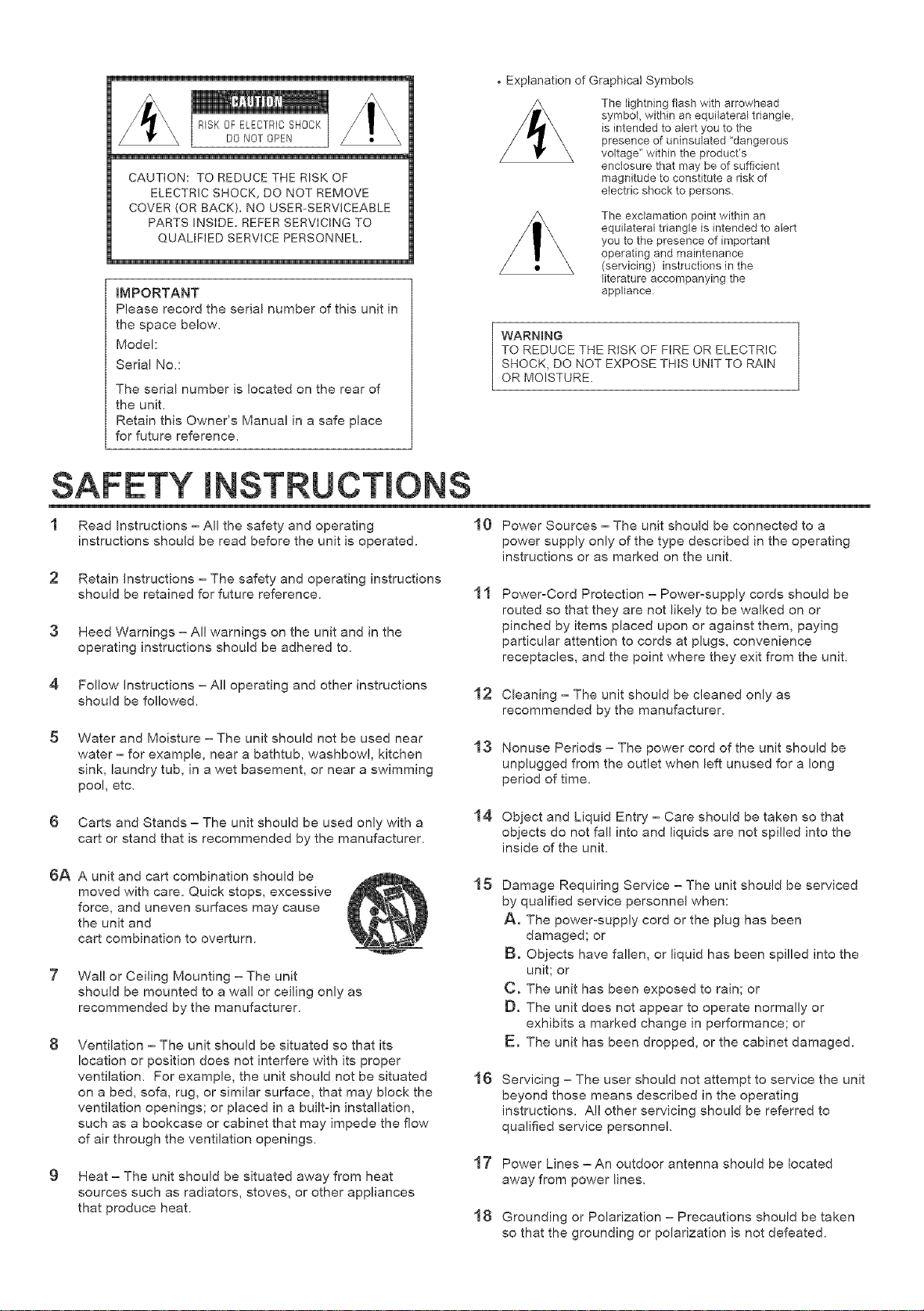
• Explanation of Graphical Symbols
The lightning flash with arrowhead
RISKOF ELECTRICSHOCK
DO NOT OPEN
CAUTION: TO REDUCE THE RISK OF
ELECTRIC SHOCK, DO NOT REMOVE
COVER (OR BACK). NO USER-SERVICEABLE
PARTS INSIDE. REFER SERVICING TO
QUALIFIED SERVICE PERSONNEL.
IMPORTANT
Please record the serial number of this unit in
the space below.
Model:
Serial No.:
The serial number is located on the rear of
the unit.
Retain this Owner's Manual in a safe place
for future reference.
WARNING
TO REDUCE THE RISK OF FIRE OR ELECTRIC
SHOCK, DO NOT EXPOSE THIS UNIT TO RAIN
OR MOISTURE.
symbol, within an equilateral triangle,
is intended to alert you to the
presence of uninsulated "dangerous
voltage" within the product's
enclosure that may be of sufficient
magnitude to constitute a risk of
electric shock to persons.
The exclamation point within an
equilateral triangle is intended to alert
you to the presence of important
operating and maintenance
(servicing) instructions in the
literature accompanying the
appliance
SAFETY INSTRLJ
1 Read Instructions - All the safety and operating 10 Power Sources - The unit should be connected to a
instructions should be read before the unit is operated.
2 Retain Instructions - The safety and operating instructions
should be retained for future reference.
3 Heed Warnings - Al! warnings on the unit and in the
operating instructions should be adhered to.
4
Follow Instructions - All operating and other instructions
should be followed.
5
Water and Moisture - The unit should not be used near
water - for example, near a bathtub, washbowl, kitchen
sink, laundry tub, in a wet basement, or near a swimming
poo!, etc.
power supply only of the type described in the operating
instructions or as marked on the unit.
11
PoweroCord Protection - Powerosupply cords should be
routed so that they are not likely to be walked on or
pinched by items placed upon or against them, paying
particular attention to cords at plugs, convenience
receptacles, and the point where they exit from the unit.
12 Cleaning - The unit should be cleaned only as
recommended by the manufacturer.
13
Nonuse Periods - The power cord of the unit should be
unplugged from the outlet when left unused for a long
period of time.
6 Carts and Stands - The unit should be used only with a
cart or stand that is recommended by the manufacturer.
6A A unit and cart combination should be
moved with care. Quick stops, excessive
force, and uneven surfaces may cause
the unit and
cart combination to overturn.
7 Wall or Ceiling Mounting - The unit
should be mounted to a wall or ceiling only as
recommended by the manufacturer.
Ventilation - The unit should be situated so that its
location or position does not interfere with its proper
ventilation. For example, the unit should not be situated
on a bed, sofa, rug, or similar surface, that may block the
ventilation openings; or placed in a built-in installation,
such as a bookcase or cabinet that may impede the flow
of air through the ventilation openings.
Heat - The unit should be situated away from heat
sources such as radiators, stoves, or other appliances
that produce heat.
14 Object and Liquid Entry - Care should be taken so that
objects do not fall into and liquids are not spilled into the
inside of the unit.
15
Damage Requiring Service - The unit should be serviced
by qualified service personnel when:
A. The power-supply cord or the plug has been
damaged; or
Bo Objects have fallen, or liquid has been spilled into the
unit; or
C, The unit has been exposed to rain; or
Do The unit does not appear to operate normally or
exhibits a marked change in performance; or
Eo The unit has been dropped, or the cabinet damaged.
16
Servicing - The user should not attempt to service the unit
beyond those means described in the operating
instructions. All other servicing should be referred to
qualified service personne!.
17
Power Lines - An outdoor antenna should be located
away from power lines.
18
Grounding or Polarization - Precautions should be taken
so that the grounding or polarization is not defeated.
Page 3
19 ForUScustomersonmy:
OutdoorAntennaGrounding= If an outside antenna is
connected to this unit, be sure the antenna system is
grounded so as to provide some protection against
voltage surges and built-up static charges. Article 810 of
the National Electrical Code, ANSI/NFPA 70, provides
information with regard to proper grounding of the mast
and supporting structure, grounding of the leadqn wire to
an antenna discharge unit, size of grounding conductors,
location of antenna discharge unit, connection to
grounding electrodes, and requirements for the grounding
electrode.
Note to CATV system installer:
This reminder is provided to call the CATV system
installer's attention to Article 820-40 of the NEC that
provides guidelines for proper grounding and, in
particular, specifies that the cable ground shall be
connected to the grounding system of the building, as
close to the point of cable entry as practical.
SPECIAL NOTES FOR FCC COMPOSITE
DEVICE (for US customers on_y)
This device is a composite system. The digital device
component may not cause harmful interference.
EXAMPLE OF ANTENNA GROUNDING
.... ELECTROOESYSTEM
NEO NATIONAL ELECTRICAL CODE
.... POWER SERVICEGROUNDING
(NEC ART250 PARTH)
FCC _NFORMATION (for US customers only)
1. mMPORTANT NOTmCE : DO NOT MODIFY THS UNIT!
This product, when installed as indicated in the
instructions contained in this manual, meets FCC
requirements. Modifications not expressly approved by
Yamaha may void your authority, granted by the FCC, to
use the product.
2. mMPORTANT : When connecting this product to
accessories and/or another product use only high quality
shielded cables. Cable/s supplied with this product
MUST be used. Follow all installation instructions.
Failure to follow instructions could void your FCC
authorization to use this product in the USA.
3. NOTE : This product has been tested and found to
comply with the requirements listed in FCC Regulations,
Part 15 for Class "B" digital devices. Compliance with
these requirements provides a reasonable level of
assurance that your use of this product in a residential
environment will not result in harmful interference with
other electronic devices.
This equipment generates/uses radio frequencies and, if
not installed and used according to the instructions
found in the users manual, may cause interference
harmful to the operation of other electronic devices.
Compliance with FCC regulations does not guarantee that
interference will not occur in all installations. If this product
is found to be the source of interference, which can be
determined by turning the unit 'OFF" and "ON", please try
to eliminate the problem by using one of the following
measures:
Relocate either this product or the device that is being
affected by the interference.
Utilize power outlets that are on different branch (circuit
breaker or fuse) circuits or install AC line filter/s.
In the case of radio or TV interference, relocate/reorient the
antenna. If the antenna leadoin is 300 ohm ribbon lead,
change the leadoin to coaxial type cable.
If these corrective measures do not produce satisfactory
results, please contact the local retailer authorized to
distribute this type of product. If you can not locate the
appropriate retailer, please contact Yamaha Electronics
Corp. U.S.A. 6660 Orangethorpe Ave, Buena Park, CA
90620.
The above statements apply ONLY to those products
distributed by Yamaha Corporation of America or its
subsidiaries.
We Want You Listening For A Lifetime (for US customers only)
YAMAHA and the Electronic Industries Association's
Consumer Electronics Group want you to get the most out of
your equipment by playing it at a safe level. One that lets the
sound come through loud and clear without annoying blaring
or distortion = and, most importantly, without affecting your
sensitive hearing.
Since hearing damage from loud sounds is often
undetectable until it is too late, YAMAHA and the
Electronic Industries Association's Consumer
Electronics Group recommend you to avoid
prolonged exposure from excessive volume levels. ,,_ ,_,_--:Hs_'_c
Page 4
@ 80W + 80W (8_) RMS Output
Power, 0.025% THD, 20-20,000 Hz
@ 90W + 90W (GO) RMS Output
Power, 0.05% THD, 20-20,000 Hz
@ High Dynamic Power, Low _mpedance
Drive Capability
@ Continuousmy Vadabme LOUDNESS Controm
@ CD D_RECT AMP Switch to Reproduce the
Purest CD Sound
@ PURE D_RECT Switch to Reproduce the
Purest Source Sound
@ 40-Station Random Access Preset Tuning
@ Automatic Preset Tuning
@ Preset Station Shifting Capability (Preset
Editing)
@ _F Count Direct PLL Synthesizer Tuning
System
@ Video Signa_ _nputlOutput Capability
@ SLEEP Timer
@ Remote Contro_ Capability
SAFETY INSTRUCTIONS ....... Inside the Front Cover
FEATURES ...................................................... 2
SUPPLIED ACCESSORIES ............................ 3
CAUTION ......................................................... 4
NOTES ABOUT THE REMOTE CONTROL
TRANSMITTER ................................................ 5
CONNECTIONS ............................................... 6
CONTROLS AND THEIR FUNCTIONS ........... 9
BASIC OPERATIONS .................................... 13
TUNING OPERATIONS ................................. 16
PRESET TUNING .......................................... 17
TROUBLESHOOTING ................................... 20
SPECIFICATIONS .......................................... 21
Page 5

After unpacking, check that the following parts are included,
Indoor FM Antenna
AM Loop Antenna
Antenna adapter (U,S.A, and Canada models only)
Remote Control Transmitter
Batteries (size AA, R6, UMo3)
3
Page 6
1.
To assure the finest performance, please read this manual
carefully. Keep it in a safe place for future reference.
2.
Install this unit in a cool, dry, clean place - away from
windows, heat sources, sources of excessive vibration,
dust, moisture and co!& Avoid sources of humming
(transformers, motors). To prevent fire or electrica! shock,
do not expose the unit to rain or water.
3.
Never open the cabinet. If something drops into the set,
contact your dealer.
4.
Do not use force on switches, controls or connection wires.
When moving the unit, first disconnect the power plug and
the wires connected to other equipment. Never pull the
wires themselves.
5.
The openings on the cabinet assure proper ventilation of
the unit. If these openings are obstructed, the temperature
inside the cabinet will rise rapidly. Therefore, avoid placing
objects against these openings, and install the unit in well-
ventilated condition. Be sure to allow a space of at least 10
cm behind, 10 cm on the both sides and 20 cm above the
top panel of the unit. Otherwise it may not only damage the
unit, but also cause fire.
6.
Always set the VOLUME control to "- oo" before starting
the audio source play. Increase the volume gradually to an
appropriate leve! after playback has been started.
7.
Do not attempt to clean the unit with chemical solvents;
this might damage the finish. Use a clean, dry cloth.
8.
Be sure to read the 'TROUBLESHOOTING" section
regarding common operating errors before concluding that
the unit is faulty.
This unit is not disconnected from the AC power source as
long as it is connected to the wall outlet, even if this unit
itself is turned off. This state is called the standby mode.
In this state, this unit is designed to consume a very small
quantity of power.
IM PORTANT
Please record the serial number of this unit in the space
below.
Model:
Serial No.:
The serial number is located on the rear of the unit.
Retain this Owner's Manual in a safe place for future
reference.
WARNING
TO REDUCE THE RISK OF FIRE OR ELECTRIC SHOCK,
DO NOT EXPOSE THIS UNIT TO RAIN OR MOISTURE.
FOR CANADIAN CUSTOMERS
TO PREVENT ELECTRIC SHOCK, MATCH WIDE BLADE
OF PLUG TO WIDE SLOT AND FULLY INSERT.
THIS CLASS B DIGITAL APPARATUS MEETS ALL
REQUIREMENTS OF THE CANADIAN INTERFERENCE-
CAUSING EQUIPMENT REGULATIONS.
.
When not planning to use this unit for long periods of time
(ie, vacation, etc.), disconnect the AC power plug from the
wal! outlet.
10.
To prevent lightning damage, disconnect the AC power
plug and antenna cable when there is an electrical storm.
11.
Grounding or polarization - Precautions should be taken
so that the grounding or polarization of an appliance is not
defeated.
12.
Do not connect audio equipment to the AC outlet on the
rear pane! if the equipment requires more power than the
outlet is rated to provide.
4
Page 7
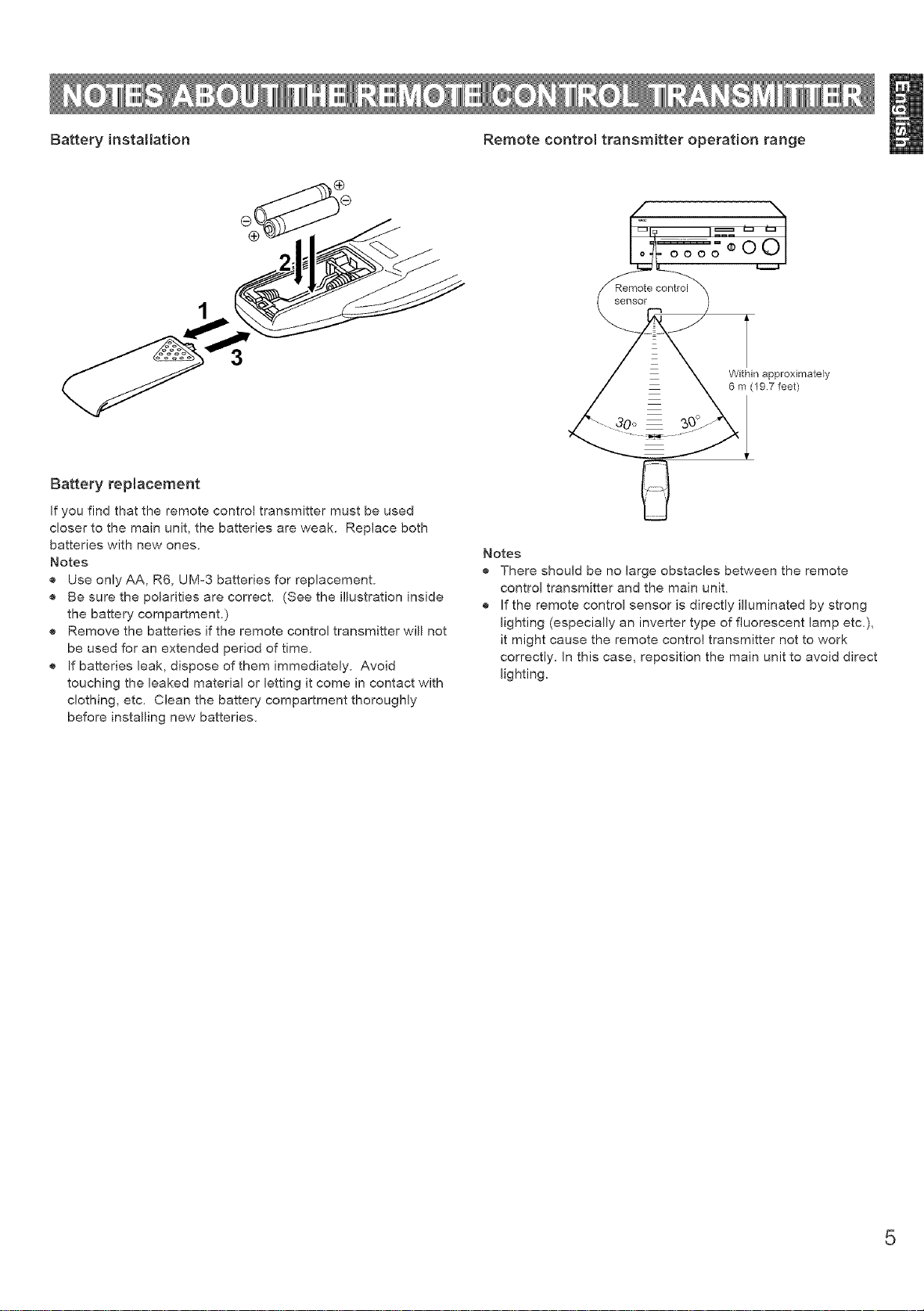
Battery installation Remote control transmitter operation range
oooo¢OO
control
sensor
Battery rep{acement
if you find that the remote control transmitter must be used
closer to the main unit, the batteries are weak. Replace both
batteries with new ones.
Notes
® Use only AA, R6, UM°3 batteries for replacement.
® Be sure the polarities are correct. (See the illustration inside
the battery compartment.)
® Remove the batteries if the remote control transmitter will not
be used for an extended period of time.
® If batteries leak, dispose of them immediately. Avoid
touching the baked material or letting it come in contact with
clothing, etc. Clean the battery compartment thoroughly
before installing new batteries.
z
30°
Notes
® There should be no large obstacles between the remote
control transmitter and the main unit.
® If the remote control sensor is directly illuminated by strong
lighting (especially an inverter type of fluorescent lamp etc.),
it might cause the remote control transmitter not to work
correctly. In this case, reposition the main unit to avoid direct
lighting.
Within approximately
6 m (19 7 feet)
5
Page 8
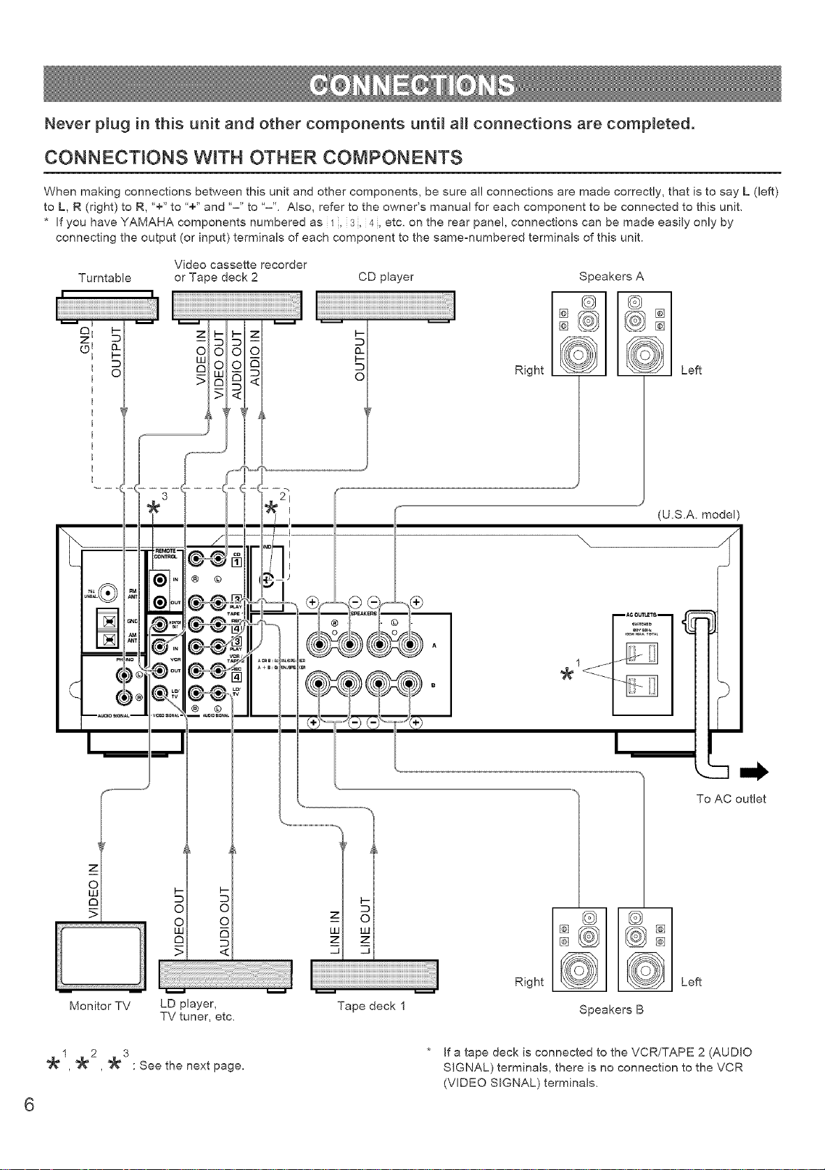
Never p_ug in this unit and other components until aH connections are completed.
CONNECTIONS WITH OTHER COMPONENTS
When making connections between this unit and other components, be sure al! connections are made correctly, that is to say L (left)
to L, R (right) to R, '+" to "+" and '-" to "-'L Also, refer to the owner's manual for each component to be connected to this unit.
* If you have YAMAHA components numbered as 1, 3, 4, etc. on the rear panel, connections can be made easily only by
connecting the output (or input) terminals of each component to the samemumbered terminals of this unit.
Video cassette recorder
Turntable or Tape deck 2
I' 'l
iiiiiiiiiiiiiiiiiiiiiiiiiiiiiiiiiiiiiiiiiiiiiiiiiiiiiiiiiiiiiiiiiiiiiiiiiiiiiiiiiiiiiiiiiiiiiiiiiiiiiiiiiiiiiiiiiiiiiiiiiiiiiiiiiiiiiiiiiiiiiiiiiiii i ! !! !
o I
z I
©I
d.
z I-
i :::D
oo
c_ O
LU
>
t- z
O O
oE
<
--
CD player
Speakers A
Left
Right
z
o
£3
Monitor TV LD player,
TV tuner, etc.
, , : See the next page.
6
Tape deck 1
Speakers B
* If a tape deck is connected to the VCR/TAPE 2 (AUDIO
SIGNAL) terminals, there is no connection to the VCR
(VIDEO SIGNAL) terminals.
Page 9
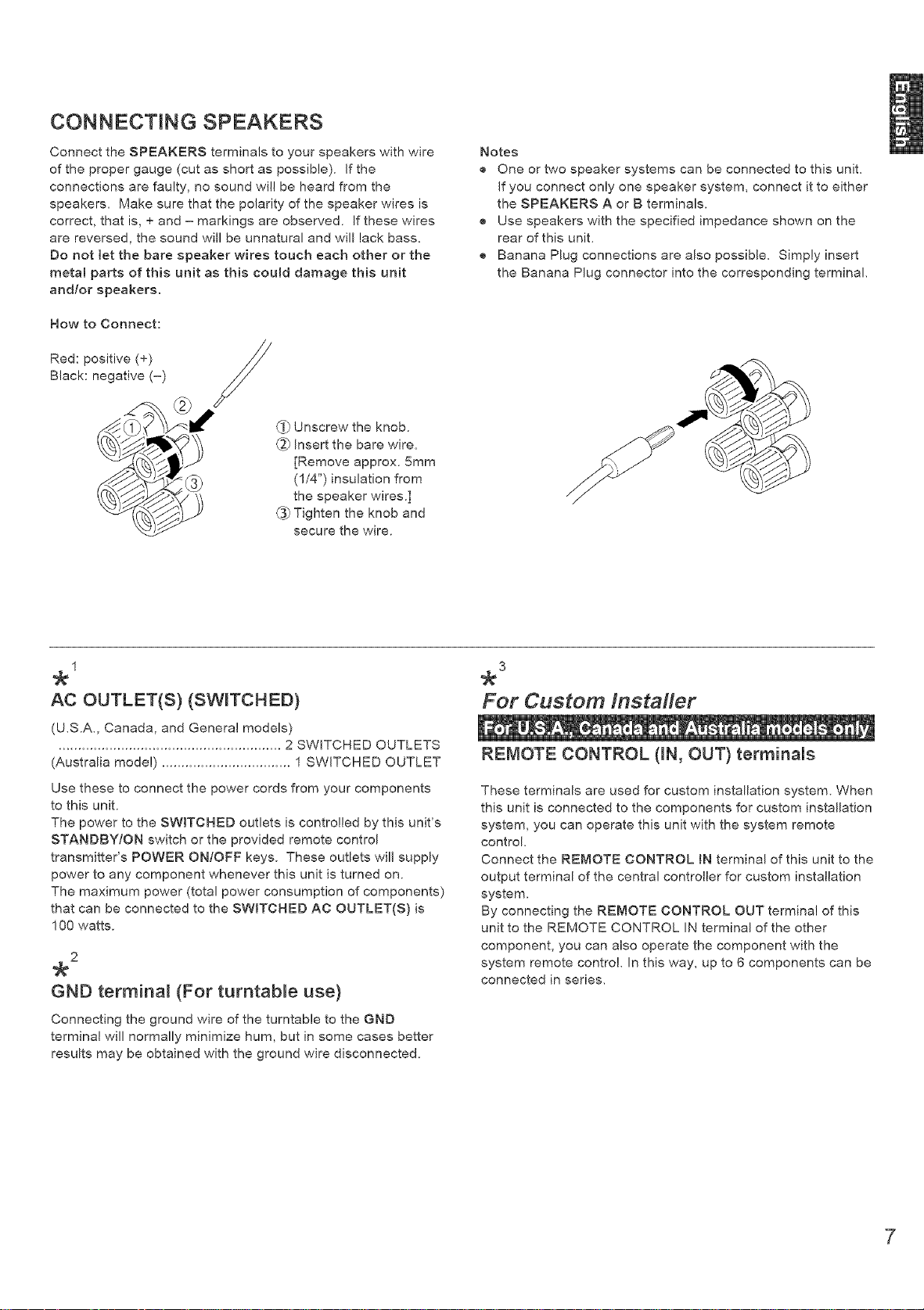
CONNECTING SPEAKERS
Connect the SPEAKERS terminals to your speakers with wire
of the proper gauge (cut as short as possible). If the
connections are faulty, no sound will be heard from the
speakers. Make sure that the polarity of the speaker wires is
correct, that is, + and - markings are observed. If these wires
are reversed, the sound will be unnatural and will lack bass.
Do not let the bare speaker wires touch each other or the
metal parts of this unit as this coumd damage this unit
and/or speakers.
How to Connect:
2
Red: positive (+) //
Black: negative (-)
/
_i.) Unscrew the knob.
(_ Insert the bare wire.
[Remove approx. 5mm
(1/4") insulation from
the speaker wires.]
_ Tighten the knob and
secure the wire.
Notes
® One or two speaker systems can be connected to this unit.
If you connect only one speaker system, connect it to either
the SPEAKERS A or B terminals.
® Use speakers with the specified impedance shown on the
rear of this unit.
® Banana Plug connections are also possible. Simply insert
the Banana Plug connector into the corresponding terminal.
1
AC OUTLET(S)(SWITCHED)
(U.S.A., Canada, and General models)
......................................................... 2 SWITCHED OUTLETS
(Australia model) ................................. 1 SWITCHED OUTLET
Use these to connect the power cords from your components
to this unit.
The power to the SWITCHED outlets is controlled by this unit's
STANDBY/ON switch or the provided remote control
transmitter's POWER ON/OFF keys. These outlets will supply
power to any component whenever this unit is turned on.
The maximum power (total power consumption of components)
that can be connected to the SWITCHED AC OUTLET{S) is
100 watts.
2
GND termina_ (For turntabme use)
Connecting the ground wire of the turntable to the GND
terminal will normally minimize hum, but in some cases better
results may be obtained with the ground wire disconnected.
For Custom Instafler
REMOTE CONTROL 0N, OUT) terminals
These terminals are used for custom installation system. When
this unit is connected to the components for custom installation
system, you can operate this unit with the system remote
control
Connect the REMOTE CONTROL IN terminal of this unit to the
output terminal of the central controller for custom installation
system.
By connecting the REMOTE CONTROL OUT terminal of this
unit to the REMOTE CONTROL IN terminal of the other
component, you can also operate the component with the
system remote control. In this way, up to 6 components can be
connected in series.
Page 10
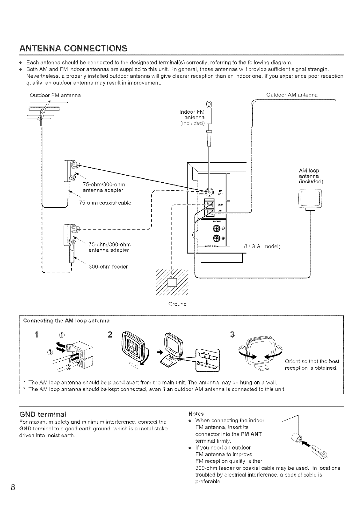
ANTENNA CONNECTIONS
® Each antenna should be connected to the designated terminal(s) correctly, referring to the following diagram.
® Both AM and FM indoor antennas are supplied to this unit. In general, these antennas will provide sufficient signal strength.
Nevertheless, a properly installed outdoor antenna wil! give clearer reception than an indoor one. If you experience poor reception
quality, an outdoor antenna may result in improvement.
Outdoor FM antenna
/_ Indoor FM
_te_ ..... "_ _ .MI/
75°ohm coaxial' cable I _ I._ _oI['"
E
............ <
" 75-ohm/300-ohm ....... _L
antenna adapter
-- I I
300°ohm feeder
Outdoor AM antenna
antenna
(included)
AM loop
antenna
(included)
(U,S.A, model)
Ground
Connecting the AM loop antenna
3
* The AM loop antenna should be placed apart from the main unit. The antenna may be hung on a wall.
* The AM loop antenna should be kept connected, even if an outdoor AM antenna is connected to this unit.
GND terminal
For maximum safety and minimum interference, connect the
GND terminal to a good earth ground, which is a metal stake
driven into moist earth.
Notes
® When connecting the indoor
FM antenna, insert its
connector into the FM ANT
terminal firmly.
® If you need an outdoor
FM antenna to improve
FM reception quality, either
300-ohm feeder or coaxial cable may be used. In locations
troubled by electrical interference, a coaxial cable is
preferable.
8
Orient so that the best
reception is obtained.
Page 11
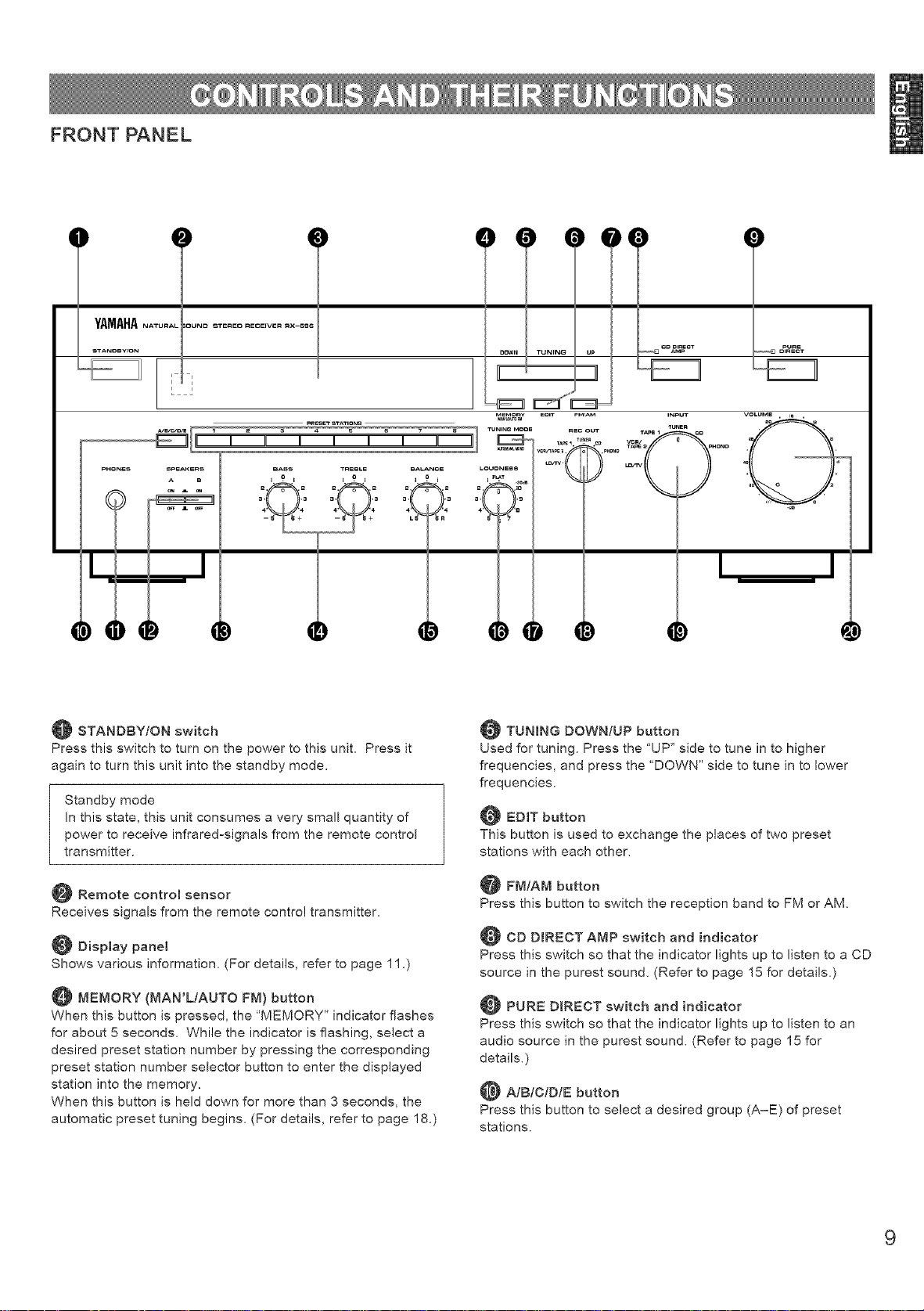
FRONT PANEL
D
STANDBY/ON switch
Press this switch to turn on the power to this unit, Press it
again to turn this unit into the standby mode,
Standby mode
In this state, this unit consumes a very small quantity of
power to receive infrared-signals from the remote control
transmitter.
_ Remote controm sensor
Receives signals from the remote control transmitter,
Display panel
Shows various information. (For details, refer to page 11 .)
MEMORY (MAN'L/AUTO FM) button
When this button is pressed, the "MEMORY" indicator flashes
for about 5 seconds. While the indicator is flashing, select a
desired preset station number by pressing the corresponding
preset station number selector button to enter the displayed
station into the memory.
When this button is held down for more than 3 seconds, the
automatic preset tuning begins. (For details, refer to page 18.)
TUNING DOWN/UP button
Used for tuning. Press the "UP" side to tune in to higher
frequencies, and press the 'DOWN" side to tune in to lower
frequencies.
EDIT button
This button is used to exchange the places of two preset
stations with each other.
@ FM/AM button
Press this button to switch the reception band to FM or AM.
CD DIRECT AMP switch and indicator
Press this switch so that the indicator lights up to listen to a CD
source in the purest sound. (Refer to page 15 for details.)
PURE DIRECT switch and indicator
Press this switch so that the indicator lights up to listen to an
audio source in the purest sound. (Refer to page 15 for
details.)
A/BIC/D/E button
Press this button to select a desired group (A-E) of preset
stations.
9
Page 12
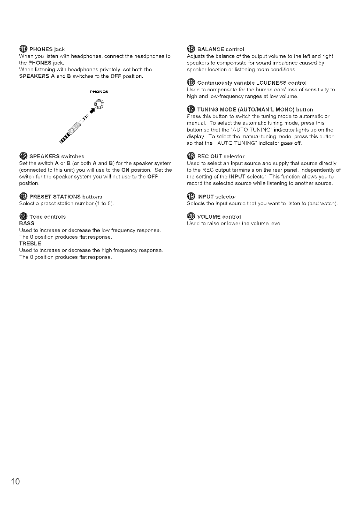
PHONES jack
When you listen with headphones, connect the headphones to
the PHONES jack.
When listening with headphones privately, set both the
SPEAKERS A and B switches to the OFF position,
PHONES
BALANCE control
Adjusts the balance of the output volume to the left and right
speakers to compensate for sound imbalance caused by
speaker location or listening room conditions.
Continuously variable LOUDNESS control
Used to compensate for the human ears' loss of sensitivity to
high and low-frequency ranges at low volume,
TUNmNG MODE (AUTO/MAN'L MONO) button
Press this button to switch the tuning mode to automatic or
manual. To select the automatic tuning mode, press this
button so that the "AUTO TUNING" indicator lights up on the
display. To select the manual tuning mode, press this button
so that the "AUTO TUNING" indicator goes off,
SPEAKERS switches
Set the switch A or B (or both A and B) for the speaker system
(connected to this unit) you will use to the ON position, Set the
switch for the speaker system you will not use to the OFF
position,
PRESET STATIONS buttons
Select a preset station number (1 to 8).
Tone controls
BASS
Used to increase or decrease the low frequency response,
The 0 position produces flat response,
TREBLE
Used to increase or decrease the high frequency response,
The 0 position produces flat response,
REC OUT semector
Used to select an input source and supply that source directly
to the REC output terminals on the rear panel, independently of
the setting of the BNPUT selector. This function allows you to
record the selected source while listening to another source,
mNPUT selector
Selects the input source that you want to listen to (and watch),
VOLUME control
Used to raise or lower the volume leve!,
10
Page 13
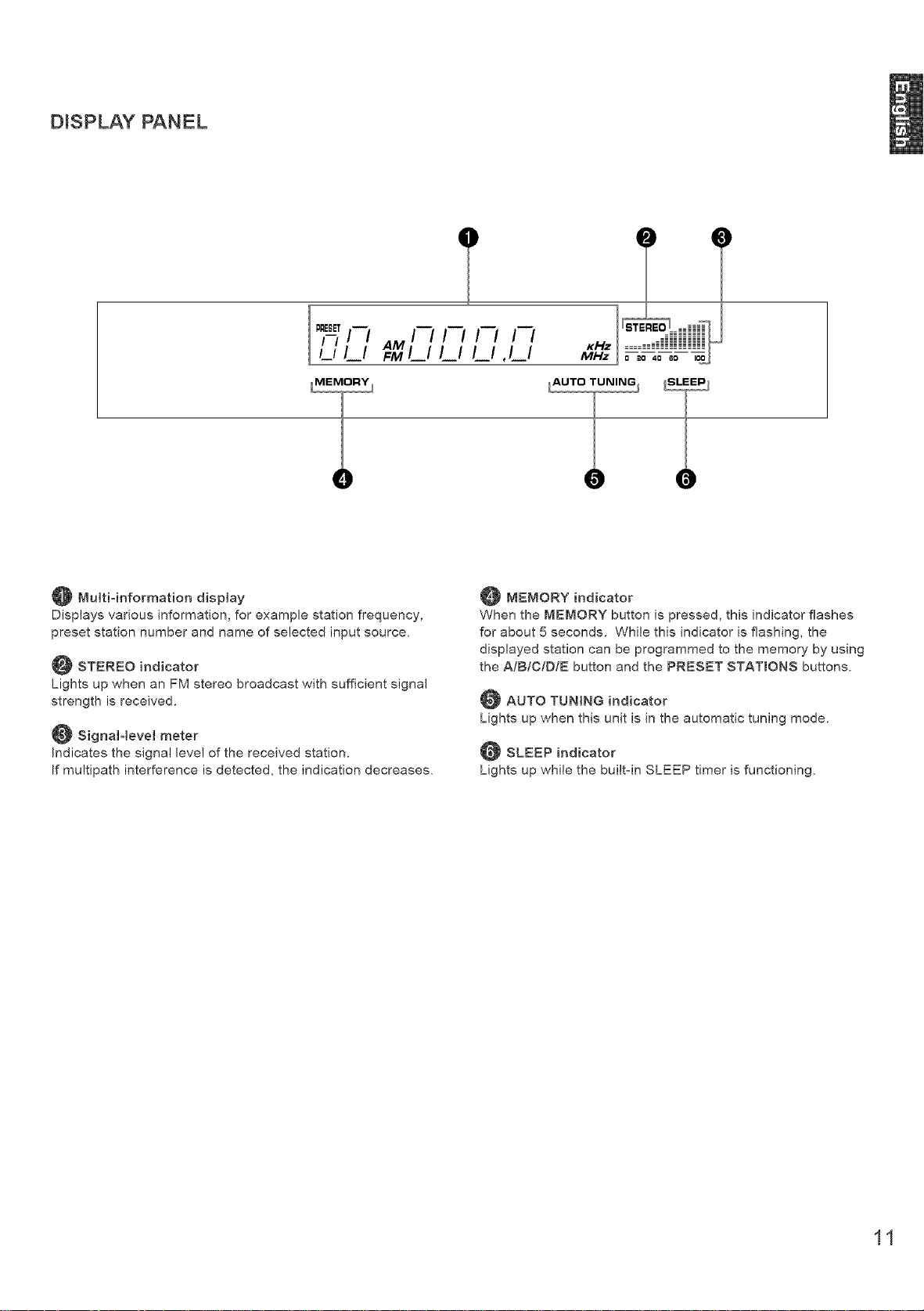
DISPLAY PANEL
II
Multi4nformation display
Displays various information, for example station frequency,
preset station number and name of selected input source.
STEREO indicator
Lights up when an FM stereo broadcast with sufficient signal
strength is received.
_ SignaHevel meter
Indicates the signal level of the received station.
If multipath interference is detected, the indication decreases.
@MEMORY indicator
When the MEMORY button is pressed, this indicator flashes
for about 5 seconds. While this indicator is flashing, the
displayed station can be programmed to the memory by using
the AIBIC/D/E button and the PRESET STATIONS buttons.
AUTO TUNING indicator
Lights up when this unit is in the automatic tuning mode.
SLEEP indicator
Lights up while the built-in SLEEP timer is functioning.
11
Page 14

REMOTE CONTROL TRANSMITTER
The remote control transmitter provided with this unit is designed to control all the most commonly used functions of this unit. If the
CD player and tape deck connected to this unit are YAMAHA components designed for remote control compatibility, this remote
control transmitter will also control various functions of each component.
For Control of This Unit
Tuner keys
Control tuner.
+: Selects higher preset station number.
=: Selects lower preset station number.
YAMAHA HIFI SYSTEM
REMOTE CONTROL TRANSMITTER
AIBIC/DIE: Selects the group (A = E) of preset station
numbers.
POWER ON and OFF keys
Pressing the POWER ON key turns the power to this unit on
and pressing the OFF key turns this unit into the standby
mode.
Bnput semector keys
Select input source.
SLEEP timer key
This unit is automatically turned into the standby mode one
hour after this key is pressed (so that SLEEP indicator lights
up).
YAMAHA
VOLUME +/= keys
Turn the volume level up/down,
For Other Component Control
Identify the remote control transmitter keys with your
component's keys. If these keys are identical, their functions
will be the same. For each key function, refer to the
corresponding instruction in your component's manual.
_Tape deck keys
Control tape deck.
* D[R A, B and A/B are applicable only to double
cassette tape deck.
* For a single cassette deck with automatic reverse
function, pressing DIR A will reverse the direction of
tape running.
_jbCD player keys
Control compact disc player.
* DISC is applicable only to compact disc changer.
12
Page 15

From page 13 to 19, this manual describes how to operate this unit mainly by using the front panel control parts.
To operate this unit on the remote control transmitter, use the corresponding keys on the remote control transmitter.
TO PLAY A SOURCE
2 7
I
4 7 3
1
2
Turn the power on.
3
Select the desired input source by using the INPUT
selector.
(For video sources, turn the TV/monitor ON.)
VOLUME , 18 ,
2O 12
28 8
'_0 4
60 2
.de
Set to the "co" position.
STANDBY/ON
INPUT
TUNER
TAPE I CD
TAPE2 PHONO
LD,'TV
4
Select the speakers to be used.
SPEAKERS
A B
ON _ ON
i )
",.j
If you use two speaker systems, press both the A and B
switches.
5
Play the source. (For detailed information on the
tuning operation, refer to page 16.)
6
VOLUME , I_ ,
28
4e O 4
C
-de
Adjust to the desired output level.
* The name of the selected input source position will
appear on the display. (For 'TUNER", the tuning mode
will appear on the display.)
* Note that selecting each input source position selects the
source which is connected to the corresponding input
terminals on the rear pane!.
If desired, adjust the BASS, TREBLE, BALANCE and
LOUDNESS controls, etc. (Refer to page 15.)
When you finish using this unit
Press the STANDBY/ON switch on the front panel again or
the POWER OFF key on the remote control transmitter to turn
this unit into the standby mode.
13
Page 16

TO RECORD A SOURCE TO TAPE (OR MD)
y_H_ .....................
1
Select the source you want to record,
REC OUT
I_NER
TAr_ I. • .CO
VCI_ftAr_LOfR/2._PHONO,
Play the source.
3
Confirm the source by selecting it with the INPUT
selector and turning up the VOLUME control,
r_ ............. _
--3
13,5
Begin recording on the tape deck (or MD recorder etc.)
or VCR connected to this unit,
To monitor the sound (and/or picture) to be recorded
select the tape deck (or VCR) being used for recording
with the INPUT selector,
INPUT
TUNER
TAPE 1 CO
TAPE 2 PHONO
LD/TV
INPUT VOLUME • _ •
TUNER • •
TAPE_I CO
V_R/ _ 28 S
LD/TV
TAPE 2_ PHONO
c
60
-SB
Notes
® If you want to enjoy another source while recording, select it
with the INPUT selector.
® VOLUME, BASS, TREBLE, BALANCE, LOUDNESS
controls, CD D_RECT AMP switch and PURE DIRECT
switch settings have no effect on the material being
recorded.
14
Page 17

Adjust the balance of the output volume to the left and right
speakers to compensate for sound imbalance caused from
speaker location or listening room conditions.
Because one or two speaker systems can be connected to this
unit, the SPEAKERS switches allow you to select speaker
system A or B, or both at once.
BALANCE
I ? I
2, • • ,2
3"0"3
4 4
L5 5R
BASS TREBLE
i .° i i .° i
3, ,3 3 ,_,34 4 4 4
5 5+ 5 5+
2, " " ,2
BASS : Turn this clockwise to increase (or counter-
clockwise to decrease the low frequency
response,
TREBLE : Turn this clockwise to increase (or counter-
clockwise to decrease) the high frequency
response.
SPEAKERS
A B
ON A ON
This control provides compensation for the human ears' loss of
sensitivity to high and IOwofrequency ranges at low volume.
This control is adjustable to retain full tonal range at any
volume leve!.
LOUONESS
I _L.AT
2, .10
3- -9
"0 a°ds
4 8
s _ 7
VOLUME , IS ,
28 8
40 4
,° i
S0 2
Set to the 'FLAT" position.
Set to the loudest listening
level that you would listen
in.
You can enjoy the purest possible CD sound from your CD
player by setting this switch so that the indicator illuminates.
By doing so, CD's input signals are sent to the builtoin special
amplifier for CD directly bypassing the BNPUT selector, BASS,
TREBLE, BALANCE and LOUDNESS controls, and then sent
to the power amplifier. This signal routing reproduces the
purest CD sound eliminating any alterations to the CD signals.
CD DIRECT
[] AMP
Note
If both CD DIRECT AMP and PURE DIRECT switches are
on, only the CD DIRECT AMP switch will function.
-de
LOUONESS
I _LAT
_" "_ volume is gained.
2.0'o Turn until the desired
4 8
e _ 7
You can enjoy the purest possible sound from your audio
sources by setting this switch so that the indicator illuminates.
By doing so, the audio signals bypass the BASS, TREBLE,
BALANCE and LOUDNESS controls, thus eliminating any
alteration to the audio signals.
PURE
[] DIRECT
15
Page 18

Normally, if station signals are strong and there is no interference, quick automatic-search tuning (AUTOMATIC TUNING) is
possible. However, if signals of the station you want to select are weak, you must tune to it manually (MANUAL TUNING).
4 2
Y_H_ .......................
=
3 1
AUTOMATIC TUNING MANUAL TUNING
1
Select "TUNER" as the input source.
INPUT
TUNER
TAPE1 CD
TAPE 2 PHONO
LDm'V
VCR/_
Select "TUNER" as the input source.
INPUT
TU_ER
TAPE1 CD
TAPE2 PHONO
L_grV
VCR/_
2
Select the reception band (FM or AM) confirming it on
the display.
..........FM or AM ...........
',,.I x \1/
/i\ /i\
3
AUTO TUNING
To tune to a higher frequency, press the right side
once.
To tune to a lower frequency, press the left side once.
OOWN TUNING UP
* If the station where tuning search stops is not the desired
one, press again.
* If the tuning search does not stop at the desired station
(because the signals of the station are weak), change to
the MANUAL TUNING method.
2
Select the reception band (FM or AM) confirming it on
the display.
FM or AM
,,,I/ \l/
/i \ /\
3
TUNFNG MODE
_ Turn the "AUTOTUNING" indicator off.
Tune to a desired station manually.
OOWN TUNING UP
* To continue tuning search, hold down the button.
Note
If you tune to an FM station manually, it is received in monaural
mode automatically to increase the signal quality.
16
Page 19

MANUAL PRESET TUNING
This unit can store station frequencies selected by tuning operation. With this function, you can recall any desired station only by
selecting the preset station number where it is stored. Up to 40 stations (8 stations x 5 groups) can be stored.
2_ 4_
E_ E23 E23
To store stations
Tune to a desired station.
(Refer to the previous page for tuning procedure.)
2
Select a desired group (A - E) of preset stations
confirming it on the display.
/1\
3
Select a preset station number where you want to
program the station before the "MEMORY" indicator
goes off from the display.
1 2 3 4 _ 6 7 8
[__11 II II I I I II II
I I / I / I I .,,idiii
/-/ I r,_ ILl _-I ,LI _., _........_-_-.-_"n"""
PRESET STATION8
/
\ /
-- MEMORY-
Flashes on and off
for about 5 seconds.
To recall a preset station
Select the group of preset stations.
A/B/P./D/E
/,/
Select the preset station number.
1 2 3 4 _ 6 7 8
I_11 II II I I I II II
Notes
" A new setting can be programmed in place of the former
one.
" For presets, the setting of the reception mode (stereo or
monaural) is stored along with the station frequency.
Memory back-up
The memory back-up circuit prevents the programmed data
from being lost even if this unit is turned into the standby
mode or the power plug is disconnected from the AC outlet or
the power is cut due to temporary power failure. If, however,
the power is cut for more than one week, the memory may be
erase& If so, it can be re-programmed by simply following
the PRESET TUNING steps.
pRE_T STATIONS
Shows the displayed station has been
programmed to A1.
* In the same way, program other stations to A2, A3 ... AS.
* You can program more stations to preset station numbers
of other groups in the same way by selecting other groups
in step 2.
17
Page 20

AUTOMATIC PRESET TUNING
You can make use of an automatic preset tuning function for FM stations. With this function, this unit performs automatic tuning and
stores FM stations with strong signals sequentially. Up to 40 stations are stored automatically in the same way as in the manual
preset tuning method on page 17.
2 3 1
V_M_H_.......................
To store stations
When the automatic preset tuning is finished;
1
\1/
FM
/1\
2
The display shows the frequency of the last preset station.
Check the contents and the number of preset stations by
following the procedure of the section 'To recall a preset
station" on page 17.
To recall a preset station
Simply follow the procedure of the section 'To recall a preset
station" on page 17.
t,.-,I
Press and hold for more
than 3 seconds.
3
To tune to higher frequencies, press right side once.
To tune to lower frequencies, press left side once.
* If the TUNING button is not pressed, in a while, the
automatic preset tuning begins automatically toward higher
frequencies.
The automatic preset tuning begins from the frequency
currently displayed. Received stations are programmed to
At, A2 _. A8 sequentially.
* If more than 8 stations are received, they are also
programmed to the preset station numbers of other groups
(B, C, D and E) in that order.
Jf you want to store the first station received by the
automatic preset tuning to a desired preset station
number;
if, for example, you want to store the first received station to
C5, select 'C5" by using the AIBICIDIE button and the
PRESET STATIONS buttons after pressing the MEMORY
button in step 2. Then press the TUNING button. The first
received station is stored to C5, and next stations to C6, C7 ...
sequentially.
if stations are stored up to E8, the automatic preset tuning is
finished automatically.
DOWN TUNING UP
/ZM_Mo.',\
Flashes.
Notes
® You can replace a preset station by another FM or AM
station manually by simply following the procedure of the
section 'To store stations" on page 17.
® If the number of received stations is not enough to be stored
up to E8, the search is finished automatically after searching
all frequencies.
® With this function, only FM stations with sufficient signal
strength are stored automatically. If the station you want to
program is weak in signal strength, tune to it in monaural
manually and program it by following the procedure of the
section 'To store stations" on page 17.
18
Page 21

EXCHANGING PRESET STATIONS
You can exchange the places of two preset stations with each other as shown below,
2, 4
Y_MAH_ ........................
r_z _ i- i
Example)
If you want to shift the preset station on E1 to A5, and vice
versa,
Recall the preset station on E1 (by following the method
of 'To recall a preset station" on page 17),
2 \_ i/
_ MEMORY
--L / --
/ [ x
Flashes_
3
Recall the preset station on A5 by following the same
method as in step 1.
__ ,q _-I __
MEMORY
/ i \
Flashes_
4
i- I _ _ I-II--
r_- I f --I --I
Shows the exchange of stations is completed.
19
Page 22

If the unit fails to operate normally, check the following points to determine whether the fault can be corrected by the simple
measures suggested. If it cannot be corrected, or if the fault is not listed in the SYMPTOM column, disconnect the power cord and
contact your authorized YAMAHA dealer or service center for help.
SYMPTOM CAUSE REMEDY
The unit fails to turn on when the STANDBY/ON Pow'er cord is not plugged in or is not completely Firmly plug M the power cord
switch is pressed. Mserted
It happens that this unit does not work There is an influence of strong external noise
normally. (lightnMg, excessive static Mectbcity, etc) or a
misoperation on this unit while using this unit.
No sound or no picture. Incorrect output cord connections
Appropriate input source is not selected.
The SPEAKERS switches are not set properly.
Speaker connections are not secure.
The sound suddenly goes off.
The protection circuit has been activated because
of short drcuit etc
The SLEEP timer has functioned
Only one side speaker outputs the sound.
Incorrect setting of the BALANCE control
Incorrect cord connections.
Sound "hums".
Incorrect cord connections.
No connection from the turntable to the GND
terminal
The volume level is low while playing a record.
The record is being played on a turntable with an
MC cartridge.
The volume level cannot be increased, or
sound is distorted.
Sound level is low. Set the LOUDNESS control to the FLAT position.
The INPUT selector will not function though it is Switch offthe CD DIRECT AMP switch
turned.
Using the BASS, TREBLE, BALANCE and The CD DIRECT AMP or PURE DIRECT switch is The CD DIRECT AMP and PURE DIRECT switches
LOUDNESS controls does not affect the tone. ON must be switched OFF to use those controls.
The component connected to the REC output
terminals of this unit is turned off.
The LOUDNESS control is functioning
The CD DIRECT AMP switch is ON
FM stereo reception is noisy. Because of the characteristics of FM stereo Check the antenna connections.
broadcasts, this is limited to cases where the Try using a high quality directional FM antenna
transmMer is too far away or the antenna input is Set the TUNING MODE button to the manual tuning
poor mode
There is distortion and clear reception cannot
be obtained even with a good FM antenna,
A desired station cannot be tuned in with the
automatic tuning method,
Previously preset stations can no longer be
tuned in,
A desired station cannot be tuned in with the
automatic tuning method,
There are continuous crackling and hissing Noises resu{t from ligtnMg, fluorescent lamps,
noises, motors, thermostats and other electrical equipment.
There is multipath interference Adjust antenna placement to eliminate multipath
The station is too weak Use the manual tuning method
This unit has been unplugged for a long period Repeat the presetting procedure.
Weak signal or loose antenna connections
There are buzzing and whining noises A tebvision set is being used nearby
(especially in the evening}.
The remote control transmitter does not work. Change the position of the main unitDirect sunlight or lighting (of an inverter type of
fluorescent lamp etc) is striking the remote control
sensor of the main unit,
The batteries of this remote control transmitter are
too weak
The sound is degraded when listening with the Turn the power to this unit on
headphones connected to the compact disc
player or cassette deck that is connected with
this unit,
This unit is in the standby mode,
Turn this unit into the standby mode and disconnect
the AC power cord from the AC outlet After about
30 seconds pass, connect the power and operate
this unit again
Connect the cords properly if the problem persists,
the cords may be defective,
Select an appropbate input source with the INPUT
selector
Set the SPEAKERS switch which corresponds to
the speakers to be used to the ON position
Secure the connections
Turn this unit into the standby mode, and then turn
on to reset the protection circuit
Cancel the SLEEP timer function
Adjust it to the appropriate position.
Connect the cords properly if the problem persists,
the cords may be defective,
Firmly connect the audio p_ugs. If the problem
persists, the cords may be defective
Make the GND connection between the turntable
and this unit
The player should be connected to the unit through
the MC head amplifier
Turn the power to the component on
interference.
Use a high quality directional FM antenna.
Tighten the AM loop antenna connections and
rotate it for best reception.
Use the manual tuning method
Use an outdoor antenna and a ground wire This
will help somewhat but it is difficult to eliminate all
the noises
Relocate this unit away from the TV.
Replace the batteries with new ones.
20
Page 23

AUDIO SECTION
Minimum RMS Output Power per Channel
8 ohms, 20 Hzto 20 kHz, 0025% THD
.................................................... 80W+SOW
6 ohms, 20 Hzto 20 kHz, 005% THD
90W+90W
Maximum Power (EIAJ) [General model only]
8 ohms, 1 kHz, 10% THD ............ 130W
6 ohms, 1 kHz_ 10% THD 150W
Dynamic Power per Channel
(by IHF Dynamic Headroom measuring
method)
8/6/4/2 oh ms .................... 120/140/180/200W
Power Band Width
8 ohms, 40W, 0.05% THD
............................................. 10 Hz to 50 kHz
Damping Factor (SPEAKERS A)
8 ohms, 20 Hz to 20 kHz ............. 240 or more
Input Sensitivity/Impedance
PHONO MM...................... 2.5 mV/47 k-ohms
CD/TAPE I/VCR.TAPE 2/LD.TV
......................................... 150 mV/47 k-ohms
Maximum input Signal
PHONO MM
1 kHz, 0.003% THD ........................ 115 mV
Output Level/Impedance
REC OUT (PHONO) ....... 150 mV/l.5 k-ohms
Headphones Jack Rated Output/impedance
Output Levet (8 ohms, 0.025% THD) .....0.3V
Impedance ..................................... 680 ohms
Frequency Response (20 Hz to 20 kHz)
CD/TAPE 1/VCR.TAPE 2/LD.TV ...... 0_+0.5dB
RIAA Equalization Deviation
PHONO MM .................................... 0_+0.5dB
Total Harmonic Distortion (20 Hz to 20 kHz)
PHONO MM to REC OUT
3V .................................................... 0.003%
CD/TAPE I/VCR.TAPE 2/LD.TV to SP OUT
40W/8 ohms ...................................... 0.01%
Signal-to-Noise Ratio (IHF-A Network)
PHONO MM (5 mV input Shorted) ....... 88 dB
CD DIRECT AMP SW: ON (Shorted)
......................................................... 110dB
Tone Control Characteristics
BASS: Boost/cut ............... _+10dB (20 Hz)
Turnover Frequency ........... 350 Hz
TREBLE: Boost/cut ............. _+10dB (20 kHz)
Turnover Frequency ..........3.5 kHz
Continuously variable LOUDNESS Control
(Level related equalization)
Attenuation ............................ -30 dB (1 kHz)
WDEO SECTION
Input Level/Impedance ........... 1 Vp-p/75 ohms
Output Level/Impedance ........ 1 Vp-p/75 ohms
FM SECTION
Tuning Range
[U.S.A and Canada models]
......................................... 87.5 to 107.9 MHz
[Australia and General models]
875 to 108.0 MHz
50 dB Quieting Sensitivity (IHF, 75 ohms)
Mono ................. 1.55 pV (15.1 dBf)
Stereo 21 pV (37.7 dBf)
Usable Sensitivity (75 ohms)
(30 dB S/N Quieting, 1 kHz, 100% mod.)
............................................. 0.8 _lV (9.3 dBf)
DIN_ Mono (SIN 26 dB) 0.9 pV
DIN, Stereo (SIN 46 dB) 24 pV
Image Response Ratio ............................ 45 dB
IF Response Ratio ................................... 70 dB
Spurious Response Ratio ............ 70 dB
AM Suppression Ratio ............... 55 dB
Capture Ratio ..........................
Alternate Channel Selectivity ......... 85 dB
Signal-to-Noise Ratio (IHF)
Mono/Stereo ............... 80 dB/75 dB
Harmonic Distortion (1 kHz)
Mono/Stereo ..................... 0. I/0 2%
Stereo Separation (1 kHz) ...................... 50 dB
Frequency Response
20 Hz to 15 kHz .............................. 0 _+1.5dB
Selectivity ................................................ 32 dB
Signal-to-Noise Ratio .............................. 50 dB
Image Response Ratio ........................... 40 dB
Spurious Response Ratio ....................... 50 dB
Harmonic Distortion (400 Hz) ................... 0.3%
AUDIO SECTION
Output Level/Impedance
FM (I00% rood, I kHz)
..................................... 500 mV/2.2 k-ohm
AM (30% rood., 400 Hz)
I50 mV/2.2 k-ohm
Power Supply
[USA. and Canada models]
.................................... AC 120V_ 60 Hz
[Australia model] ........... AC 240V, 50 Hz
[General model]
........... AC 110/I 20/220/240V, 60/50 Hz
Power Consumption
[U.S.A. medet] ...................................... 190W
[Canada modet] ....................... 250W, 320VA
[Australia and General models] ............ 210W
Maximum Power Consumption
[General model only] ............................ 450W
AC Outlets
2 SWITCHED OUTLETS
[U.S.A., Canada and General modets]
.......................................... 100W max. total
1 SWITCHED OUTLET
[Australia model] ................ 100W max. total
Dimensions (W x H x D)
...................................... 435 x 151 x 389.8 mm
(17-1/8" x 5-15/16" x 15-3/8")
Weight ............................ 9.5 kg (20 Ibs. 14 oz.)
Accessories ........................... AM loop antenna
Indoor FM antenna
Remote controt transmitter
Batteries
Antenna adapter
(U.S.A. and Canada models only)
Residual Noise (tHF-A Network)
CD DIRECT AMP SW: ON .......... 35 pV
PURE DIRECT SW: ON 90 pV
Channel Separation
CD/TAPE 1/VCR.TAPE 2/LD.TV
(Input 5.1 k-ohms Terminated, 1 kHz)
........................................................... 65 dB
AM SECTION
Tuning Range
[U.S.A, Canada and General models]
.................................... 530 to 1_710 kHz
[Australia modet] .......... 53I to 1,611 kHz
Usable Sensitivity .............................. 100 pV/m
Specifications are subject to change without
notice.
21
Page 24

Nous vous rememions d'avoir porte votre choix sur ce r6cepteur ster6o YAMAHA.
@ Puissance de sortie RMS de 80W + 80W
(8 ohms), distorsion harmonique totale de
0,025%, 20-20.000 Nz
@ Puissance de sortie RMS de 90W + 90W
(6 ohms), distorsion harmonique totale de
0,05%, 20-20.000 Nz
@ Grande puissance dynamique,
entrainement _ impedance faib_e
@ Commande de compensation
physiologique continueHement variable
(LOUDNESS}
@ Interrupteur CD DIRECT AMP pour
obtenir _e son CD _e p_us fid_e
@ Interrupteur PURE DIRECT pour _a
reproduction _a p_us fid_e du son
d'origine
@ Pr_r_glage de syntonisation a_atoire
pour 40 stations
@ Syntonisation pr_r_gl_e automatique
@ Fonction de permutation des stations
pr_r_gl_es (Montage prOrOgUe)
@ Syst_me de syntonisation par
synth_tiseur PLL direct en iF
@ Entr_elsortie video possible
@ Minuterie de Sommei_
@ Fonctionnement par t_commande
CARACTERISTIQUES .................................. 22
ACCESSOIRES FOURNIS ........................... 23
ATTENTION .................................................. 23
REMARQUES CONCERNANT LA
TELECOMMANDE ........................................ 24
RACCORDEMENTS ..................................... 25
LES COMMANDES ET LEURS
FONCTIONS ................................................. 29
FONCTIONNEMENT DE BASE .................... 32
SYNTONISATION ......................................... 35
SYNTONISATION PREREGLEE .................. 36
EN CAS DE DIFFICULTE ............................. 39
CARACTERISTIQUES TECHNIQUES ......... 40
Page 25

Apres le deballage, verifier que les pieces suivantes sont incluses,
Antenne FM interieure
Cadre=antenne AM
Piles (tai!le AA, R6, UM-3)
Adaptateur d'antenne
(Modeles pour les Etats=Unis et le Canada
seulement)
Emetteur de tel6commande
Pour garantir les meilleures performances possible, lire ce
manuel avec attention, Le garder dans un endroit sOr pour
une ref6rence future.
2_
installer votre appareil darts un endroit frais, sec et propre,
loin de fen6tres, sources de chaleur et d'endroits oQ les
vibrations, la poussiere, I'humidite ou le froid sont
importants. Eviter les sources de bourdonnements
(transformateurs, moteurs). Pour eviter les incendies ou
chocs electriques, ne pas exposer I'appareil a la pluie ni
I'humidite,
3_
Ne jamais ouvrir le coffret. Si un objet pen6tre darts
I'appareil, contacter votre revendeur.
4.
Ne pas forcer les commutateurs, boutons ou cables.
Lors du deplacement de I'appareil, d'abord debrancher la
prise d'alimentation et les cables le raccordant a d'autres
appareils, Ne jamais tirer sur le cordon.
5_
Les ouvertures pratiquees sur le coffret assurent une
ventilation adequate de !'appareil. Si ces ouvertures sont
bouchees, la temperature va s'elever rapidement
I'interieur de !'apparei!. Par consequent, eviter de placer
des objets sur ces ouvertures, et installer I'apparei! darts
un endroit suffisamment ventile. Veiller a laisser un espace
d'au moins 10 cm derriere, 10 cm sur les deux c6tes et
20 cm au-dessus du panneau superieur de I'apparei!.
Sinon, non seulement on risque d'endommager I'appareil,
mais aussi de provoquer un incendie,
6,
Toujours regler la commande de volume sur "- oo" avant
de commencer la lecture d'une source audio; augmenter
petit a petit le volume jusqu'a un niveau adequat une fois
que la lecture a commence,
7,
Ne pas essayer de nettoyer I'appareil avec des diluants
chimiques, ceci endommagerait le fini, Utiliser un chiffon
propre et sec,
8,
Bien lire la section "EN CAS DE DIFFICULTE" concernant
les erreurs de fonctionnement communes avant de
conclure que votre appareil est en panne,
9,
Lorsqu'on prevoit de ne pas utiliser cet appareil pendant
Iongtemps (pendant les vacances, par exemple),
debrancher le cordon d'alimentation CA de la prise de
courant secteur,
1 0. Pour eviter des endommagements dus a Forage,
debrancher la prise d'alimentation CA et le cable
d'antenne en cas d'orage,
1 1. Mise a la terre ou polarisation - Des precautions doivent
6tre prises de maniere a ce que la mise a la terre ou la
polarisation d'un appareil ne soit pas annulee,
1 2. Ne pas raccorder d'appareil audio aux prises CA du
panneau arriere si I'appareil demande plus d'alimentation
que la valeur nominale fournie par les prises,
23
Page 26

mMPORTANT
Noter le numero de serie de votre appareil dans I'espace ci-
dessous.
Modele
N ° de serie:
Le numero de serie se trouve a I'arriere de I'appareil.
Garder le manuel d'instructions dans un endroit sot pour
une ref6rence future.
POUR LES CONSOMMATEURS CANADIENS
POUR EVITER LES CHOCS ELECTRIQUES, INTRODUIRE
LA LAME LA PLUS LARGE DE LA FICHE DANS LA BORNE
CORRESPONDANTE DE LA PRISE ET POUSSER
JUSQU'AU FOND.
CETAPPAREIL NUMERIQUE DE LA CLASSE B
RESPECTE TOUTES LES EXIGENCES DU REGLEMENT
SUR LE MATERIEL BROUILLEUR DU CANADA.
AVERTJSSEMENT
Afin d'eviter tout risque d'incendie ou d'electrocution, ne pas
exposer I'appareil a la pluie ni a !'humidite.
Mise en place des piles
÷(
Cet appareil n'est pas d6connecte de la source
d'alimentation CA tant qu'il est branche a la prise secteur,
m6me si Fappareil !ui-m6me est mis hers tension. Cet etat
est appele mode d'attente.
Dans cet etat, I'appareil consomme une tres faible quantite
de courant.
Pottle de fonctionnement de la t_l_commande
D
oooo°O0
provenant de ]a
telecornmande
Remplacement de piles
Si Iorsque I'on utilise la tel6commande il est necessaire de la
rapprocher de I'appareil, les piles sont sans doute decharg6es.
Dans ce cas, remplacer les deux piles par des neuves.
Remarques
® N'utiliser que des piles AA, R6, UM-3 pour le remplacement
des piles.
® Veiller ace que les polarites soient respectees. (Voir
I'illustration se trouvant dans le compartiment des piles.)
® Lorsque I'on n'utilise pas la tel6commande pendant un
certain temps, retirer les piles de la tel6commande.
® Si les piles fuient, les jeter immediatement. Ne pas toucher
I'electroiyte et veiller ace qu'il n'entre pas en contact avec
des v6tements, etc. Nettoyer soigneusement le
compartiment des piles avant de mettre en place des piles
neuves.
24
Portee de 6 metres
envirolq
Remarques
® En outre, veiller & ce qu'il n'y ait aucun obstacle entre la
tel6commande et I'appareil.
® Si le detecteur de tel6commande est expose directement
une forte lure!ere (provenant d'une lampe fluorescente de
type inverseur, etc.), il se peut que la tel6commande ne
fonctionne pas correctement. Dans ce cas, changer la
position de I'appareil principal de fa£;on a eviter une
exposition directe.
Page 27

Ne jamais brancher cet apparei_ et _es autres composants avant d'avoir accomp_i tous _es
raccordements.
RACCORDEMENTS A D'AUTRES APPAREILS
Lors du raccordement de cet appareil aux autres composants veiller & ce que tousles branchements soient effectues correctement,
c'estoaodire entre "L" (gauche) et 'L", entre 'R" (droite) et "R", entre '+" et "+" et entre '-" et "-",
Voir aussi le mode d'emploi de chaque appareil branche & cet appareil.
* S'il y a des composants YAMAHA numerot6s 1, 3, 4, etc. sur le panneau arriere, il est possible d'effectuer facilement les
raccordements en raccordant les bomes de sortie (ou d'entree) de chaque composant aux bomes portant les m6mes numeros sur
cet appareil,
Platine tourne-
disque
Magnetoscope ou
Platine & cassette 2
Lecteur de disque
compact
Enceintes A
I
z t-
t- z
z I
i
O
0 0
o5
uJ
5_
>
<
S
0
Droite
Gauche
® ©
2_1
I
(Modele pour
les Etats-Unis)
Vers une prise CA
Moniteur TV Lecteur Laser Disc,
,,k1 ,,k2 ,,k3
, , : Voir la page suivante,
syntonisateur TV, etc,
z
LId
z
-s
Platine a cassette 1
Droite Gauche
Enceintes B
Au cas oO une platine a cassette est raccordee aux
bornes VCR/TAPE 2 (AUDIO SIGNAL), il n'y a pas de
connexion aux bornes VCR (VIDEO SIGNAL).
25
Page 28

RACCORDEMENT DES ENCEtNTES
Raccorder les bornes SPEAKERS aux enceintes avec des
cables de section adequate et aussi courts que possible. Si les
branchements sont mal faits, aucun son ne sera entendu aux
enceintes. Respecter la polarite des cables de raccord
(reperes + et -). Si les polarites sont inversees, le son per£su
manquera de naturel et de profondeur de basses. Veiller _ ce
que [es portions d_nud_es des c_b[es ne se touchent pas
ou n'entrent pas en contact avec les pi&ces m&talliques de
cet appareil, car cela pourrait endommager I'appareil et/ou
[es enceintes.
Branchement:
Rouge: positif (+)
Noir: negatif (=)
/
{17Devisser le bouton.
(_) Introduire le cable
denud6.
(Enlever environ 5 mm
de gafne pour denuder
le cable.)
(3) Revisser le bouton et
fixer le cable.
Remarques
® Une ou deux paires d'enceintes peuvent 6tre branchees &
cet apparei!. Pour le raccord d'une seule paire d'enceintes,
choisir les bornes d'enceintes (SPEAKERS) A ou B.
® Utiliser des enceintes dont I'impedance correspond a la
valeur indiquee a !'arriere de I'appareil.
® I! est egalement possible d'utiliser des fiches banane. II
suffit d'introduire la fiche banane dans la borne
correspondante.
Prise(s) CA [AC OUTLET(S) (SWITCHED)]
(Modeles pour les Etats-Unis, le Canada et gen6ral)
................................................................... 2 prises commutees
(Mod&le pour I'Australie) ................................ 1 prise commutee
Brancher a ces prises les cordons d'alimentation des appareils
qui composent la chai"ne Hi Fi.
L'al[mentation aux prises commutees SWITCHED est
contrSlee par I'interrupteur STANDBY/ON de cet appareil ou
les touches POWER ON/OFF de la t61ecommande fournie. En
d'autres termes, Iorsque I'appareil est mis sous tension, tous
les appareils qui sont raccordes aces prises seront aussi sous
tension.
La puissance totale maximum (puissance cumulee de tousles
appareils branches) autorisee est de 100 watts au(x) prise(s)
commutee(s) SWITCHED.
2
Borne de raise _ la terre (GND)
(Pour le tourne°disque)
En branchant le cable de raise a la terre d'un tourne-disque a
la borne de mise a la terre, on obtient en gen6ral une
r_,duction du ronflement. Cependant, dans certains cas, les
resultats sont meilleurs si le cable de mise a la terre reste
debranch&
Pour l'instaltateur d'un syst#.me
sp#.cial
Bomes de tei6commande REIVIOTE CONTROL
(iN,OUT)
Ces bomes sont utilisees pour le systeme d'installation
speciale. Lorsque cet appareil est raccorde aux composants du
systeme d'installation speciale, il est possible de faire
fonctionner !'apparel! au moyen de la te!6commande.
Raccorder la borne REMOTE CONTROL _N de cet appareil a
la borne de sortie du contr61eur centrale pour le systeme
d'installation personnalisee.
En raccordant la borne REMOTE CONTROL OUT de cet
apparel! a la borne REMOTE CONTROL IN de Fautre appareil,
il est aussi possible de le faire fonctionner au moyen de la
t6iecommande. De cette fagon, il est possible de raccorder en
serie 6 composants au maximum.
26
Page 29

RACCORDEMENTS DES ANTENNES
® Raccorder chaque antenne correctement aux bornes design6es, se!on les schemas ci-dessous.
® Les deux antennes AM et FM interieures sont fournies avec cet appareil.
En gen6ral, ces antennes sont d'une sensibilite adequate. Cependant, une antenne exterieure installee correctement donnera
une reception plus claire qu'une antenne interieure. Si vous obtenez une qualite de reception mediocre, une antenne extedeure
pourra ameliorer la situation.
Antenne FM exterieure
Antenne FM (
interieure
(incluse)
Antenne AM exterieure
Cadre°
antenne AM
(incluse)
"C&b,ecoaxialde75ohms I
"_" Adaptateur d'antenne ,oooZ/L
75 ohms/300 ohms
(Modele pour les Etats-Unis)
I I
C_ble plat de 300 ohms
Mise a la terre
Raccordement de le cadreoantenne AM
* Le cadre-antenne AM dolt 6tre place a un endroit separ6 de I'appareil principal.
* Toujours laisser le cadre-antenne AM branchee m6me si on utilise aussi une antenne AM exterieure.
Borne de raise _ la terre (GND)
Pour une securit6 maximale et une interference minimale,
raccorder la borne GND a une bonne raise a la terre. Une
bonne prise de terre se fait par un piquet de metal plante dans
une terre humide.
Remarques
® Lorsqu'on branche une antenne
interieure FM, inserer
fermement son connecteur
dans la borne FM ANT.
® Si une antenne FM exterieure
s'avere necessaire pour
ameliorer la qualite de la
reception FM, choisir soit un c&ble de 300 ohms, soit un
c_ble coaxial. Le c_ble coaxial est pref6rable Iorsque le lieu
d'utilisation de I'appareil est g6n6 par des interferences
electriques.
Orienter I'antenne de
maniere & obtenir la
meilleure reception.
Page 30

PANNEAU AVANT
D
PHONES
I
puma
DmeCT
VOLUME • ie •
m
I
,)(
@ [nterrupteur d'attente/marche (STANDBY/ON)
Le presser pour mettre cet apparei! en marche. Le presser &
nouveau pour mettre cet appareil en mode d'attente,
Mode d'attente
Dans cet etat, cet appareil consomme une tres faible
quantite de courant lui permettant de recevoir les signaux
infrarouge de la telecommande.
O Capteur de t&_commande
II repoit les signaux transmis par la telecommande.
_ Panneau d'affichage
Indique diverses informations. (Pour plus de details, voir la
page 30.)
Touche de m@moire/FM auto/manue_
(MEMORY, _AN'L/AUTO FM)
Lorsqu'on appuie sur cette touche, I'indicateur "MEMORY"
clignote pendant environ 5 secondes. Pendant cette periode,
choisir un numero de station prereglee desire en appuyant sur
le selecteur de numero de station prereglee correspondant
pour memoriser la station affichee.
Lorsqu'on maintient cette touche enfoncee pendant plus de 3
secondes, la syntonisation prereglee automatique commence.
(Pour plus de details, voir la page 37.)
Touche de syntonisation bas/haut (TUNING DOWN/UP)
Ella permet de syntoniser les stations. Appuyer sur le c6te
"UP" pour syntoniser des frequences plus hautes, et sur le
c6te 'DOWN" pour syntoniser des frequences plus basses.
Touche Edition (EDIT)
Cette touche est utilisee pour permuter les positions de deux
stations prereglees.
Touche FM/AM
Presser cette touche pour commuter la gamme de reception
sur FM ou AM,
hterrupteur et t_moin d'amp_ification directe du
disque compact (CD D_RECT AMP)
Enfoncer cat interrupteur de maniere que le temoin s'allume
pour ecouter un disque compact avec le son le plus pur
possible. (Pour plus de details, se reporter & la page 34,)
@ hterrupteur et t_moin de son put direct (PURE
D_RECT)
Appuyer sur cet interrupteur de maniere que le temoin s'a!lume
pour ecouter une source sonore avec le son le plus pur
possible. (Pour plus de details, se reporter a la page 34,)
Touche AIBIC/D/E
Appuyer sur cette touche pour selectionner un groupe desire
(A-E) de stations prereglees.
28
Page 31

Prise de casque d'_coute (PHONES)
Pour effectuer une ecoute au casque, brancher le casque
d'ecoute a la prise pour casque (PHONES). Pour obtenir une
ecoute au casque exc!usivement, regler les deux interrupteurs
d'enceintes SPEAKERS Aet B sur la position OFF.
Commande de I'&quilibre sonore (BALANCE)
Regle I'equilibre des sons entre les enceintes gauche et droite
pour compenser tout d6sequilibre provoque par un
emplacement particulier des enceintes ou une disposition
particuliere de la piece d'ecoute.
PHONES
[nterrupteurs d'enceintes (SPEAKERS)
Mettre Finterrupteur A ou B (ou les deux interrupteurs A et B),
correspondant a Fenceinte ou aux enceintes (raccordees a cet
appareil) que I'on veut utiliser, sur la position 'ON". Mettre
I'interrupteur de I'enceinte que I'on ne veut pas utiliser sur la
position 'OFF".
Touches de stations pr_r_gl&es (PRESET STATIONS)
IIs permettent de selectionner un numero de station prer6g!6e
(1 a 8).
Commandes de tonalit_
Basses (BASS)
Erie permet d'augmenter ou de diminuer la reponse en basses
frequences. La position O correspond a une reponse neutre.
Aigus (TREBLE)
Erie permet d'augmenter ou de diminuer la reponse en hautes
frequences. La position 0 correspond a une reponse neutre.
Commande de compensation physio[ogique
continue[[ement variable (LOUDNESS)
Elle permet de compenser la perte de sensibilite de I'oreille
pour les frequences basses et elev6es lots d'une ecoute
faible volume.
Touche de mode de syntonisation automatique/
manuel mono (TUNING MODE, AUTO/MAN'L MONO)
Appuyer sur cette touche pour passer sur le mode de
syntonisation automatique ou manuel. Pour selectionner le
mode de syntonisation automatique, appuyer sur cette touche
de maniere que Findicateur 'AUTO TUNING" s'allume sur
I'affichage. Pour selectionner le mode de syntonisation manuel,
appuyer sur cette touche de maniere que I'indicateur 'AUTO
TUNING" s'eteigne.
@ S_[ecteur de sortie d'enregistrement (REC OUT)
II permet de selectionner une source d'entree et de faire
parvenir cette source directement aux bornes de sortie REC du
panneau arriere, et ce quel que soit le reglage du selecteur
INPUT. Cette fonction permet d'enregistrer la source
selectionn6e tout en ecoutant une autre source.
@ S_lecteur d'entr_e (INPUT)
Sert a selectionner la source d'entree que I'on desire ecouter
(et regarder).
Commande du niveau de volume sonore (VOLUME)
Elle permet d'augmenter ou de diminuer le niveau du volume,
29
Page 32

PANNEAU D'AFFICHAGE
II
_ _ AMI--_/--/ /--/ /T
Affichage multi4nformations
II affiche diverses informations, par exemple la frequence de
station, le numero de station prer6gl6e et le nom de la source
d'entree selectionn6e.
Bndicateur de st6r6o (STEREO)
S'allume Iorsqu'une emission ster6o FM possedant un signal
suffisamment fort est regue.
Compteur de niveau de signal
Indique le niveau de signal de la station revue.
Si des interferences fant6mes sont d6tectees, I'indication du
niveau du signal diminue.
Indicateur de m6moire (MEMORY)
Quand la touche MEMORY est pressee, cet indicateur clignote
pendant environ 5 secondes. Pendant cette periode, la station
affichee peut 6tre memoris6e avec la touche A/B/ClDIE et les
touches PRESET STATIONS.
Indicateur de syntonisation automatique (AUTO
TUNING)
S'allume Iorsque cet appareil est darts le mode de
syntonisation automatique.
[ndicateur de minuterie de sommei[ (SLEEP)
II s'allume Iorsque la minuterie de sommeil est en fonction.
30
Page 33

TELECOMMANDE
La tel6commande fournie avec cet appareil permet de commander toutes les fonctions les plus utilisees de cet appareil. Si le lecteur
de disque compact et la platine a cassette raccordes a cet apparel! sont des appareils YAMAHA compatibles avec le
fonctionnement tel6commande, alors il sera aussi possible de commander les diverses fonctions de chacun des appareils avec
cette tel6commande.
Pour commander cet appareil
Touches de syntonisateur
Ces touches permettent de commander le syntonisateur.
+: Selectionne le numero de station prer6gl6e superieur.
=: Selectionne le numero de station prer6g!6e inferieur.
YAMAHA HIFI SYSTEM
REMOTE CONTROL TRANSMITTER
A/B/C/DIE: Permettent de selectionner les numeros de
stations prer6gl6es des groupes correspondants
(A a E).
Touches d'alimentation et de raise hors tension
(POWER ON et OFF)
Lorsqu'on appuie sur la touche POWER ON, I'appareil est mis
en circuit; Iorsqu'on appuie sur la touche OFF, I'appareil est
mis en mode d'attente.
@ S_lecteurs d'entr&e
IIs permettent de selectionner la source d'entree,
YAMAHA
Touche de minuterie de sommei[ (SLEEP)
Cet appareil est mis automatiquement en mode d'attente une
heure apres qu'on ait appuye sur cette touche (de maniere
que I'indication SLEEP s'allume).
Touches d'augmentation/diminution de volume
sonore (VOLUME +/-}
Ces touches permettent d'augmenter et de diminuer le
volume.
Pour la commande des autres appareils
Identifier les touches de la te!6commande & Faide des touches
de I'appareil. Si ces touches sont identiques, leurs fonctions
seront aussi identiques. En ce qui concerne les fonctions des
touches, se reporter a !'instruction correspondante du manuel
de Fappareil.
_) Touches de platine _ cassette
Elles permettent de commander une platine a cassette.
* Les touches DIR A, Bet A/B sont utilisables seulement
avec une platine a deux cassettes.
* Pour les platines a une seule cassette equip6es de la
fonction de rebobinage automatique, le sens de defilement
de la bande sera inverse Iorsqu'on appuie sur la touche
DIR A.
_jb Touches de lecteur de disque compact
Elles permettent de commander un lecteur de disque compact.
* La touche DISC est utilisable seulement avec un changeur
de disques compacts.
31
Page 34

De la page 32 a la page 38, ce mode d'emploi decrit principalement la maniere de faire fonctionner cet appareil au moyen des
commandes du panneau avant. Pour faire fonctionner cet appareil au moyen de la t6iecommande, utiliser les touches de la
tel6commande portant le m_me nom que celles du panneau avant.
REPRODUCTION D'UNESOURCE
2 7
4 7 3
1
VOLUME • 18 ,
2O 12
28 8
40 4
60 2
-dE
Regler a la position "co"
2
Mettre I'appareil sous tension.
STANDBY/ON
3
Selectionner la source d'entree desir6e au moyen du
selecteur d'entree _NPUT.
(Pour ce qui conceme les sources video, mettre sous
tension le te!6viseur ou le moniteur.)
INPUT
TIJ_ER
TAI_E I CD
TAPE 2 pHONO
L_ZTV
Le nom de la position de source d'entree selectionn6e
appara'_t & I'affichage. (Pour "TUNER", le mode de
syntonisation apparai"t a I'affichage.)
Bien noter que le fait de selectionner chacune des
positions de source d'entree a pour resultat d'acceder
la source qui est raccordee aux bomes d'entree
correspondantes situees sur le panneau arriere.
4
Selectionner les enceintes que I'on veut utiliser.
SPEAKERS
A B
.,'
Lorsqu'on utilise deux paires d'enceintes enfoncer les
interrupteurs A et B.
5
Mettre en marche la source. (Pour les informations
detaill6es concernant le syntonisateur, se reporter a la
page 35.)
6
VOLUME , IS ,
ae 12
28 S
4e 4
_B
Regler le volume au niveau desir6.
Le cas echeant, regler les commandes BASS,
TREBLE, BALANCE et LOUDNESS, etc. (Se reporter
la page 34.).
Apr_s avoir utiiis_ cet appareH
Appuyer a nouveau sur I'interrupteur STANDBY/ON du
panneau avant ou sur la touche POWER OFF de la
telecommande pour faire passer cet appareil au mode
d'attente.
32
Page 35

ENREGISTREMENT D'UNE SOURCE SUR UNE BANDE MAGNETIQUE (OU UN MINIDJSQUE)
y_t_H_ .......................
--3
13,5
1
Selectionner la source que I'on veut enregistrer.
REC OUT
_NER
TAr_ I. • CO
VCI_frAr_LD/_/2._PHON0,
Mettre en marche la source.
3
Verifier la source en la selectionnant & I'aide du
selecteur INPUT et en augmentant le niveau de la
commande VOLUME,
INPUT VOLUME • _ ,
TUNER • •
TAPE_I CD
VCR/ _ ze 8
LD/TV
TAPE 2_ PHONO
coo
Enclencher I'enregistrement sur la platine a cassette
(ou magnetophone & minidisque, etc,) ou sur le
magnetoscope raccorde a cet appareil,
5
Pour contr6Eer les sons a enregistrer (et/ou I'image),
selectionner la platine a cassette (ou le magnetoscope)
utilisee pour I'enregistrement au moyen du selecteur
mNPUT.
INPUT
TUNER
TAPE 1 CD
TAPE 2 PHONO
LDfrV
Remarques
® Pour ecouter une autre source en cours d'enregistrement, la
2
_B
selectionner a I'aide du selecteur mNPUT.
® Le reglage des commandes VOLUME, BASS, TREBLE,
BALANCE, LOUDNESS, de I'interrupteur CD D_RECT AMP
et de I'interrupteur PURE DIRECT n'affecte pas
I'enregistrement.
33
Page 36

Regler I'equilibre des sons entre les enceintes gauche et
droite pour compenser tout des6quilibre provoque par un
emplacement particulier des enceintes ou une disposition
particuliere de la piece d'ecoute.
BALANCE
j .O I
2. " " ,2
3.Q. 3
4 4
L5 5R
Une ou deux paires d'enceintes peuvent 6tre branchees a cet
appareik Les commutateurs d'enceintes SPEAKERS
permettent de faire la selection de la paire A ou B choisie, ou
des deux paires simultanement.
SPEAKERS
A B
ON _ ON
O_ Jt O_
BASS TREBLE
i ? i i .° i
Q 2. • ' .2
3, ,3 3 ._.3
4 4 4 4
5 5+ 5 5+
Basses (BASS) : Tourner la commande vers la droite pour
accentuer les sons de basse frequence,
vers la gauche pour les diminuer.
Aigus (TREBLE) : Toumer la commande vers la droite pour
accentuer les sons de haute frequence,
vers la gauche pour les diminuer.
II est possible d'obtenir le son CD le plus fidele possible du
lecteur de disque compact en reglant cet interrupteur de
maniere que le temoin s'allume. En ce faisant, les signaux
d'entree du disque compact sont envoyes directement
ramplificateur specia! pour disque compact en contournant le
selecteur BNPUT, les commandes BASS, TREBLE,
BALANCE et LOUDNESS, et sont ensuite envoyes
I'amplificateur. Ce mode d'acheminement des signaux permet
d'obtenir une grande fidelit6 du son CD en eliminant toutes les
alt@ations des signaux de disque compact.
Lots d'une ecoute a volume faible, cette commande compense
la perte de sensibilite de roreille humaine pour les frequences
basses et elev6es. Cette commande est reglable afin de
conserver une portee tonale etendue, quel que soit le niveau
de volume des sons.
LOUDNESS
, FL.*, Regler a la position
2. .,o "FLAT".
3* .8
.Q_0dB
4 8
B _ 7
2
VOLUME , IS ,
28 8
40 4
c.o,O
SO 2
-aB
LOUDNESS
i FLAT
• " -30ds
3* .8
{..©,o
4" "8
s _ 7
Regler a son niveau
d'ecoute le plue fort,
Tourner jusqu'a ce que le
volume d6sire soit obtenu.
CC DIRECT
[] AMP
Remarque
Si les interrupteurs CD DIRECT AMP et PURE D{RECT
sont tous deux en position 'ON", I'interrupteur CD DIRECT
AMP seulement fonctionnera,
34
En reglant cet interrupteur de fa£son que le temoin s'allume, il
est possible d'obtenir le son le plus pur des sources audio. En
ce faisant, les signaux audio contoument les commandes
BASS, TREBLE, BALANCE et LOUDNESS, ce qui permet
d'eliminer toute alteration des signaux audio.
PURE
[] DIRECT
Page 37

Lorsque les signaux des stations sont forts et qu'il n'y apas d'interferences, la syntonisation rapide avec recherche automatique
(SYNTONISATION AUTOMATIQUE) est possible. Cependant, si les signaux de la station desirGe sont faibles, il faudra avoir
recours & une syntonisaton manuelle (SYNTONISATION MANUELLE).
4 2
yAM_H_ .......................
• =
0 _ '"" '" :'': "_ :_'
.... _ _©.:.0.:©. "I/
L_J
3 I
SYNTONISATION AUTOMATIQUE
1
Selectionner "TUNER" comme source d'entree.
INPUT
TUNER
TAPE 1 CD
TAPE 2 PHONO
UDm'V
VCR/
2
Selectionner la gamme (FM ou AM) de la station
desirGe, tout en la verifiant sur I'affichage.
,,I/ \I/
..........FM ...... ou ..........AM ..........
/i \ /\
3
TUNrNG MODE \\
' ' _ AUTO TUNING
SYNTONISATION MANUELLE
Selectionner "TUNER" comme source d'entree.
INPUT
TUNER
TAPE 1 CD
TAPE2 PHONO
LDfrV
2
Selectionner la gamme (FM ou AM) de la station
dGsiree, tout en la verifiant sur I'affichage.
FM ou AM
,,,I/ \I/
/i \ /\
3
TUNFN_ MOOE
_ Eteindre I'indicateur"AUTO TUNING".
Pour syntoniser une frequence plus elevGe, appuyer
une fois sur le cSte droit de la touche.
Pour syntoniser une frequence plus basse, appuyer
une fois sur le cSte gauche de la touche.
OOWN TUNING_ UP
* Lorsque le mecanisme de recherche de station s'arrGte sur
une station qui n'est pas la station dGsiree, appuyer
nouveau sur la touche.
* Lorsque le mecanisme de recherche de station ne s'arrGte
pas sur la station desirGe (parce que les signaux de la station
d'emission sont trop faibles), employer la methode de
SYNTONISATION MANUELLE decrite a la page suivante.
Syntoniser manuellement sur la station desirGe.
DOWN TUNIN(_ UP
* Pour continuer la recherche de station, appuyer sur la
touche et la maintenir enfoncee.
Remarque
Lorsqu'on syntonise I'appareil manuellement sur une station
FM, cette station est regue en mode mono, pour permettre
d'ameliorer la qualite de reception des signaux.
35
Page 38

SYNTON!SATION PREREGLEE MANUELLE
Cet appareil peut memoriser la frequence des stations d'emission selectionn6e par syntonisation. Grace a cette fonction, il suffit de
selectionner le numero de station prer6gl6e sur lequel elle est memoris6e pour rappeler la station correspondante. II est possible de
memoriser jusqu'a 40 stations (8 stations sur chacun des 5 groupes).
3
Y_H_ ......................
I
M_morisation des stations
Syntoniser I'appareil sur la station desir6e.
(Se reporter a la page prec6dente pour des informations
detaill6es.)
2
Selectionner le groupe desir6 (A = E) des stations
prer6gl6es tout en le verifiant sur Faffichage.
/1\
3
\ J
-- MEMORY-
J \
Clignote pendant
environ 5 secondes.
Selectionner un numero de station prer6gl6e a I'endroit
oQ !'on vent programmer la station avant que Findicateur
'MEMORY" disparaisse de I'affichage.
1 2 3 4 _ 6 7 8
I_11 II II I I I II II
/ /-//-/ Iq _.,uiiiiii
I _,M IL-I ZI,LI _N, _'-,'_-'-2
Indique que la station affichee a et6
programmee sur A1.
pRESE'r STA'rlI_,I8
/
Pour rappeler une station pr_r_gl_e
Selectionner le groupe de stations prer6gl6es.
:)i;¸
//
Appuyer sur le numero correspondant a la station
prereglee.
1 2 3 4 _ 6 7 8
L_II II II I I I II II
Remarquea
'_ Toute nouveile programmation de station sur une touche de
prereglage efface la programmation precedente.
'_ Le mode de reception (mono ou stereo) est programme en
m_me temps que la frequence de la station.
M_moire de maintien
Le circuit de memoire de maintien evite que les informations
programmees ne soient perdues, si par exemple on met cet
appareil en mode d'attente, ou si la fiche d'alimentation est
retiree de la prise CA, ou encore si le courant est coupe
cause d'une panne de courant.
Si Falimentation est coupee pendant plus d'une semaine, la
memoire peut _tre effac(_,e. Dans ce cas, elle peut _tre
reprogrammee en suivant le processus de SYNTONISATION
PREREGLEE.
A/B/_iI_/E
PRESET _TA'rlON8
* Programmer de la m6me maniere les stations desir6es sur
A2, A3 ... A8.
* De la m6me maniere, il est possible de programmer plus
de stations sur des numeros de pr6reglage de stations
d'autres groupes en selectionnant d'autres groupes
Foperation 2.
36
Page 39

SYNTONtSATION PREREGLEE AUTOMATIQUE
I! est aussi possible d'utiliser la fonction de syntonisation prer6gl6e automatique pour les stations FM seulement. Grace a cette
fonction, I'appareil peut effectuer la syntonisation automatique et la memorisation ordonnee des stations FM emettant des signaux
puissants. Jusqu'a 40 stations peuvent 6tre memoris6es automatiquement sur les touches de prer6glage de station en suivant une
methode similaire a celle indiquee a la page 36 pour la syntonisation prer6gl6e manuelle.
2 3 1
M_morisation des stations
Pour programmer la premiere station regue par
i
2
Appuyer sur la touche
et la maintenir enfoncee
pendant plus de 3
seoondes.
3
DOWN TUNING UP
FM
"\1/
/1\
[\j
Clignote.
syntonisation pr_r_g!_e automatique sur le num_ro
de station pr_r_gl_e voulu;
si Fon veut par exemple programmer la premiere station regue
sur C5, selectionner 'C5" au moyen de la touche A/B/C/D/E et
des touches PRESET STATIONS apres avoir appuy& sur la
touche MEMORY a !'etape 2. Appuyer ensuite sur la touche
TUNING. La premiere station revue est programmee sur C5, et
les stations suivantes sont programmees dans Fordre sur C6,
07...
Lorsque la programmation des stations a (_t6 accomplie sur
tousles numeros jusqu'a E8, la syntonisation prer6gl6e
automatique s'arr6te automatiquement.
Lorsque la syntonisation prer_gl_e automatique est
termin_e;
L'affichage donne la frequence de la derniere station prereglee.
V&rifier la nature et le hombre de stations pr®lees en
suivant la procedure decrite a la section 'Pour rappeler une
station prereglee" a la page 36.
,__2
Pour syntoniser des frequences plus hautes, appuyer une
fois sur le c6te droit.
Pour syntoniser des frequences plus basses, appuyer une
fois sur le c6te gauche.
* Un instant apres, si Fon n'appuie pas sur la touche TUNING,
la syntonisation prer6gl6e automatique commence
automatiquement vers les frequences plus hautes.
La syntonisation prer6gl6e automatique commence a partir
de la frequence actuellement affichee. Les stations regues
sont programmees dans Fordre sur A1, A2__A8.
* Si plus de 8 stations sont regues, elles sont aussi
programmees sur les numeros de stations prer6gl6es des
autres groupes (B, C, D et E) dans cet ordre.
Pout rappeler une station pr_r_g!_e
l! suffit de suivre la procedure decrite a la section "Pour
rappeler une station prereglee" a la page 36.
Remarques
® II est possible de remplacer manuellement une station
prereglee par une autre station FM ou AM en suivant
simplement la procedure decrite a la section ' Memorisation
des stations" a la page 36.
® Si le hombre de stations regues ne suffit pas & remplir tous
les numeros de stations prereglees iusqu'a E8, la recherche
se terminera aprils avoir recherche toutes les frequences de
stations.
® Avec cette fonction, seules les stations FM emettant un
signal suffisamment puissant peuvent _tre memorisees
automatiquement. Si la station que I'on veut programmer
emet un signal faible, il faut la syntoniser manuellement en
mono et la programmer en suivant la procedure decrite & la
section "Memorisation des stations" a la page 36.
37
Page 40

PERMUTATION DE STATIONS PREREGLEES
II est possible de permuter les touches de memorisation de deux stations prer6gl6es de la maniere indiquee ci°dessous,
2, 4
y_MAHA ...........................
Exemple:
Pour permuter la station prer6gl6e de E1 a A5, et vice-versa.
Rappeler la station prer6gl6e sur E1 (en suivant la
methode decrite a la section 'Pour rappeler une station
prer6gl6e" a la page 36).
2
--C / __
MEMORY
/ \
Clignote.
Ensuite, rappeler la station prer6gl6e sur A5 en suivant
la m6me methode qu'a I'etape 1.
\___, I1_ ,/
_14 q _
MEMORY
/ i \
Clignote.
4
i- I _ _ 171--
r_- I r-i _1
Indique que la permutation des stations est terminee,
38
Page 41

Si I'appareil ne fonctionne pas correctement, avant de conclure qu'il est en panne, le verifier selon la liste suivante de problemes
possibles. Cette liste donne des details sur los remedes que vous pouvez appliquer vous-m6me sans avoir a appeler un
specialiste, Si vous avez queique doute ou question, consulter votre revendeur officie! YAMAHA le plus proche,
SYMPTOME CAUSE REMEDE
L'appareil ne ee met pae seas tension Iorequ'on Le cordon d alimentation n'est pas branche oune Bien brancher le cordon d alimentation.
appuie sur Finterrupteur STANDBY/ON. I'est pas completement
Cut appareH ne fonetionne pae normalement. II y a interference de bruits extedeurs puissants
(orage, electdcite statique excessive, etc) ou on a
effectue une operation erronee en utilisant cut
appareil
Pae de son ou pae d'image. Mauvais raccordement des c_bles de sortie.
Selection d entree incorrecte.
Les interrupteurs SPEAKERS ne sent pas
correctement regles.
hes connexions des enceintes ne sent pas correctes
Le son ee coupe eoudainement.
Le circuit de protection s'est declenche dO a un
court-circuit, etc
La minutede SLEEP a ete activee
t3
Lee sons ne sent 6mie aux eneeintee que d'un
E
5. seulc6t_.
E
Le son "bourdonne',
La commande BALANCE n'est pas correctement regl6e
Mauvais raccordement des c_bles.
Mauvais raccordement des c_bles.
Le toume-disque nest pas raccorde a une prise de
mise ale terre.
Le niveau de volume eet bas _ la lecture d'un Le disque est lu surun tourne-disque avec ce}lule
dieque, aimant mobile
II eet impossible d'augmenter le niveau de Lappareil brenche aux barnes de sortie REC de cet
volume, ouil y a une distorsion du son= appareil est hers tension.
Le volume sonore eet faiMe. La fonction de compensation physiologique Placer la commande LOUDNESS sur la position
(LOUDNESS) est activee. FLAT (reponse plate).
II eet impossible de changer la source d'entr_e, L interrupteur CD DIRECT AMP est place sur la Mettre I interrupteur CD DIRECT AMP sur la
bien que le s_leeteur INPUT eoit active, position "ON'. position "OFF"
Lee eommandee BASS, TREBLE, BALANCE et L interrapteur CD DIRECT AMP ou PURE DIRECT Los interrupteurs CD DIRECT AMP et PURE
LOUDNESS ne fonctJonnent pae. est regle sur la position "ON' DIRECT doivent etre places sur la position "OFF"
La r_ception FM st_r_o eet parasit_e. A cause des caracteristiques des emissions FM Verifier les raccordements de I antenne.
stereo, ceci est limite aux cas ok I'emetteur est Essayer d utiliser une antenne FM a eEements
eloigne ou quand I'entree d'antenne est faible multiples
H y a de la dietorsion et une r_eeption claire ne
peat pae _tre obtenue, m_me avee une bonne
antenne FM,
Une station voulue ne pout pae &tre syntonis_e
avee la m_thode de eyntonieation automatique.
Lee stations pr_r_gl_ee pr_alablement ne
peuvent plus &tre syntonie_ee.
Une station voulue ne pout pae _tre syntonis_e
aveela m_thode de syntonieation automatique.
II y a dee craquemente continue et dee bruits de
sifflement.
II y a des interferences fant6mes Ajuster I'emplacement de I'antenne pour eliminer les
La station est trap faible. Utiliser la methode de syntonisation manuelle
Cet appareit a ete debranche pendant Iongtemps. Recommencer le prereglage.
Signal faible ou raccordements I_ches de Iantenne.
Ce sent des bruits provenant d'eclairages, de
lampes fluorescentes, de moteurs, de thermostats
et d autres equipements electdques
II y a dee bruits de ronflemente et d'ondee
Un televiseur est utilise pres de Vappareil
(en partieulier le eoir}.
La t_l_commande ne fonctionne pae.
E
E
8
Le detecteur de telecommande de I'appareil principal
est expos@ a la lumi@re dimcte du soleil (ou d'une
lampe fluorescente de type inverseur, etc )
Les piles de cette telecommande sent trop faibles
Lee sons ee d_gradent Iorequ'on _eoute avec un
casque reii_ _ un leeteur de disque eompaet ou
_ une p_atine _ cassette raeeord_e _ eet
appareiL
Cet appareit est en mode d'attente
Faire passer cet appareil au mode d'attente et
debrancher le cordon d'alimentation de la prise
secteur. Apres environ trente secondes, retablir
Valimentation et utiliser a nouveau cet appareil.
Raccorder correctement les cgbles. Sile probleme
persiste, les c_bles sent peut-etre en mauvais etat.
Selectionner une source d'entree correcte au
moyen du selecteur INPUT.
Regler I'interrupteur SPEAKERS correspondant aux
enceintes que I'on utilise sur la position "ON _
Effectuer des connexions correctes.
Mettre cet appareil en mode d attente puis le
rallumer pour remettre a zero le circuit de
protection.
Desactiver la minutede SLEEP
Regler correctement la commande.
Raccorder correctement les c_bles. Si le probleme
persiste, les cgbles sent peut-etre en mauvais etet.
Raccorder fermement les prises audio Sile probleme
persiste, le c_ble est peut-etre en mauvais etat
Faire le branchement de raise a la terre entre le
toume-disque et cet appareil
Raccorder le tourne-disque a Vappareil par le biais
de I'amplificateur a tote a aimant mobile
Mettre Iappareil concerne sous tension.
pour pouvoir utiliser ces commandes.
Regler la touche TUNING MODE sur le mode de
syntonisation manuelle
interferences fant6mes
Utiliser une antenne FM directionnel[e de bonne
qualite.
Resserrer les raccordements du cadre-antenne AM
et le faire tourner de facon a obtenir la meilleure
reception possible
Utiliser la methode de syntonisation manuelle
Utiliser une antenne exterieure et un c_ble de raise
{a terre Ceci aidera mais it est difficite d eliminer
tout le bruit
E[oigner cet apparei{ du televiseur
Changer la position de I'appareil principal.
Remplacer les piles
Mettre cet appareil sous tension.
39
Page 42

SECTION AUDIO
Puissance de sortie minimum RMS par canal
8 ohms, 20 Hz _ 20 kHz, 0,025% de DHT
...................................................... 80W+80W
6 ohms, 20 Hz _ 20 kHz, 0,05% de DHT
...................................................... 90W+90W
Puissance maximale (EIAJ) [Modele general
seutement]
8 ohms, 1 kHz, 10% de DHT ............... 130W
6 ohms, 1 kHz, 10% de DHT ............... 150W
Puissance dynamique par canal
(Mesuree par ta methode tHF Dynamic
Headroom)
8/6/4/2 oh ms .................... 120/140/180/200W
Largeur de bande de puissance
8 ohms, 40W, 0,05% de DHT
.............................................. 10 Hz_ 50 kHz
Facteur d'amortissement (SPEAKERS A)
8 ohms, 20 Hz _ 20 kHz ........... 240 ou moins
Sensibitite d'entree/impedance
PHONO MM...................... 2,5 mY/47 k-ohms
CD/TAPE I/VCR.TAPE 2/LD.TV
......................................... 150 mV/47 k-ohms
Signat d'entree maximum
PHONO MM
1 kHz, 0,003% de DHT ................... 115 mV
Niveau de sortie/impedance
REC OUT (PHONO) ....... 150 mV/l,5 k-ohms
Sortie nominale de prise de
casque/impedance
Niveau de sortie (8 ohms, 0,025% de DHT)
................................................................ 0,3V
Impedance ..................................... 680 ohms
Reponse en frequence (20 Hz a 20 kHz)
CD/TAPE 1/VCR.TAPE 2/LD.TV
........................................................ 0_+0,5 dB
Deviation d'egalisation RIAA
PHONO MM .................................... 0_+0,5 dB
Distorsion harmonique totate (20 Hz a 20 kHz)
PHONO MM to REC OUT
3V .................................................... 0,003%
CD/TAPE I/VCR.TAPE 2/LD.TV a SP OUT
40W/8 ohms ...................................... 0,01%
Rapport signal/bruit (tHF reseau A)
PHONO MIVl
(5 mV entree court-circuitee) ............. 88 dB
CD DIRECT AMP SW: ON
(court-circuitee) ................................ 110 dB
Bruit residuet (IHF reseau A)
CD DIRECT AMP SW: ON ........... 35 I_V
PURE DIRECT SW: ON 90 pV
Separation des canaux
CD/TAPE 1/VCR.TAPE 2/LD.TV
(entree terminee 5,1 k-ohms, 1 kHz)
........................................................... 65 dB
Carateristiques de contr6te de ta tonalite
BASS: Augmentation/coupure
.............................. _+10dB (20 Hz)
Frequence de retablissement
........................................... 350 Hz
TREBLE: Augmentation/coupure
............................. _+10dB (20 kHz)
Frequence de retablissement
........................................... 3,5 kHz
Commande de compensation physiologique
continueliement variable (LOUDNESS)
(Egaiisation reliee au niveau)
Attenuation .......................... -30 dB (1 kHz)
SECTION VIDEO
Niveau d'entree/impedance ._.1 Vc.c/75 ohms
Niveau de sortie/impedance ...1 Vc.c/75 ohms
SECTION FM
Gamme de syntonisation
[Modeles pour tes Etats-Unis et te Canada]
........................................... 87,5 _ 107,9 MHz
[Modeles pour t'Australie et general]
........................................... 87,5 a 108,0 MHz
Sensibilite de silencieux 50 dB (tHF, 75 ohms)
Mono ................................. 1,55 pV (15,1 dBf)
Stereo .................................. 21 pV (37,7 dBf)
Sensibiiite utilisable (75 ohms)
(silencieux S/B 30 dB, 1 kHz, 100% de rood.)
............................................. 0,8 _._V(9,3 dBf)
DIN, Mono (26 dB) ............................... 0,9 pV
DIN, Stereo (46 dB) .............................. 24 pV
Rapport de reponse d'image ................... 45 dB
Rapport de reponse Ft ............................ 70 dB
Rapport de reponse de bruit ................... 70 dB
Rapport de suppression AM ................... 55 dB
Rapport de capture ................................ 1,5 dB
Selectivite de canal atterne .................... 85 dB
Rapport signal/bruit (IHF)
Mono/Stereo ............................... 80 dB/75 dB
Distorsion harmonique (1 kHz)
Mono/Stereo .................................... 0,1/0,2%
Separation stereo (1 kHz) ....................... 50 dB
Reponse en frequence
20 Hz a 15 kHz ................................ 0_+1,5dB
SECTION AiV]
Gamme de syntonisation
[Modeles pour tes Etats-Unis, le Canada et
general] ................................ 530 a 1.710 kHz
[Modele pour FAustralie]
............................................. 531 _ 1.611 kHz
Sensibilite utitisabIe ........................... 100 #V/m
Selectivite ................................................ 32 dB
Rapport signal/bruit ................................. 50 dB
Rapport de reponse d'image ................... 40 dB
Rapport de reponse de bruit ................... 50 dB
Distorsion harmonique (400 Hz) .............. 0,3%
SECTION AUDIO
Niveau de sortie/impedance
FM (100% de mod., 1 kHz)
..................................... 500 mV/2,2 k-ohms
AM (30% de mod., 400 kHz)
........................................ 150 mV/2,2 k-ohms
Atimentation
[Modeles pour tes Etats-Unis et le Canada]
............................................. CA 120V, 60 Hz
[Modele pour FAustralie] ....... CA 240V, 50 Hz
[Modele generat]
................... CA 110/120/220/240V, 60/50 Hz
Consommation
[Modele pour tes Etats-Unis] ................ 190W
[Modele pour Ie Canada] ......... 250W, 320VA
[Modeles pour FAustralie et general]
.............................................................. 210W
Consommation maximale [Modele general
seutement] ............................................. 450W
Prises CA
2 PRISES COMMUTEES
[Modetes pour les Etats-Unis, te Canada et
generat] ........................ 100W max. au total
1 PRISE COMMUTEE
[Mod@te pour I'Australie]
..................................... 100W max. au total
Dimensions (L x H x P)
...................................... 435x 151 x 389,8 mm
Poids ....................................................... 9,5 kg
Accessoires ........................ Cadre-antenne AM
Antenne FM int_rieure
Emetteur de tetecommande
Piles
Adaptateur d'antenne (Modeles pour les
Etats-Unis et te Canada seulement)
40
Caracteristiques techniques modifiabtes sans
preavis.
Page 43

YAMAHA
YAMAHA ELECTRONICS CORPORATION, USA 6660 ORANGETHORPE AVE BUENA PARK CAL}F 90620 U S A
YAMAHA CANADA MUSIC LTD 135 M_LNER AVE, SC_ARBOROUGH ONTARIO M_S 3R/ CANADA
YAMAHA ELECTRONIK EUROPA Gm.bH SIEMFNSSTR 22 3,1 25462 RELLING_N BEI HAMBURG F R OF GERMANY
YAMAHA ELECTRON_QUE FRANCE SA RU _ AMBRO_SE CROIZAT BF'70 CROISSY BEAUBOURG 77312 MARNE /A VALL_F CFD_X02 FRANCE
YAMAHA ELECTRONICS (UK} LTD YAMAHA HOUSE¸ 200 RICKMANSWORFH ROAD WATFORD HFRFS WDI 7JS ENGLAND
YAMAHA 8CANDINAVEA AB J A WETTERGRENS GATA I BOX 30053 400 43 VASTRA FROLUNDA SWEDEN
YAMAHA MUSIC AUSTRALIA PTY, LTD 17 33 _,_ARK_T ST SOUTH MELBOURN_ 32O5 VIC AUSTRALIA
YAMAHA CORPORATION
VZ85310 Printed in Malaysia
 Loading...