

Page 1

OWNER’S MANUAL
MANUEL DU PROPRIÉTAIRE
USO E MANUTENZIONE
INSTRUKTIONSBOK
OMISTAJAN KÄSIKIRJA
EIERHÅNDBOK
E
F
I
S
SF
N
E
F
S
SF
N
Read this manual carefully before operating this vehicle.
Il convient de lire attentivement ce manuel avant la première utilisation du véhicule.
I
Leggere attentamente questo manuale prima di utilizzare questo veicolo.
Läs den här instruktionsboken noga innan snöskotern används.
Lue tämä käsikirja huolellisesti ennen moottorikelkan käyttöä.
Les denne håndboken nøye før du tar kjøretøyet i bruk.
RX10PSE
RX10PXTE
8HG-28199-S3
Page 2

Original instructions
Notice originale
Istruzioni originali
Bruksanvisning i original
Alkuperäiset ohjeet
Opprinnelige instruksjoner
PRINTED IN JAPAN
2013.06-0.3×1 CR
PRINTED ON RECYCLED PAPER
IMPRIMÉ SUR PAPIER RECYCLÉ
STAMPATO SU CARTA RICICLATA
TRYCKT PÅ ÅTERVUNNET PAPPER
PAINETTU UUSIOPAPERILLE
TRYKKET PÅ RESIRKULERT PAPIR
Page 3
Read this manual carefully
before operating this vehicle.
OWNER’S MANUAL
RX10PSE
RX10PXTE
8HG-28199-S3-E0
Page 4
ESU14033
Read this manual carefully before operating this vehicle. This manual
should stay with this vehicle if it is sold.
EC Declaration of Conformity
conforming to Directive 2006/42/EC
We, YAMAHA MOTOR CO., LTD. 2500 Shingai, Iwata, Japan,
declare in sole responsibility, that the product
RX10GT2 (RX10PS
RX10ST2 (RX10PXT
to which this declaration applies, conforms to the essential health and safety
requirements of Directive 2006/42/EC
(
If applicable
and to the other relevant Directive of EEC
(
If applicable
To effect correct
stated in the Directives of EEC, the
specifications were consulted:
)
(
Title and
/
or number and date of issue of the other Directives of EEC
)
application
(
Title and
/
or number and date of issue of standards and/or specifications
Authorized Representative
YAMAHA MOTOR EUROPE N.V.
Koolhovenlaan 101, 1119 NC Schiphol-Rijk, The Netherlands
) (
JYE8JC00∗EA003507-
) (
JYE8HN00
(
Make, model
2004/108/EC
of the
essential
following-standards and/or
)
health
∗
– – – – – –
Signature
General Manager
Engineering Div., RV Business Unit
Business Development Operations
Date of Issue
Akihiro Tsuzuki
7 November, 2012
EA007714-
and safety requirements
)
)
)
technical
)
Page 5
ESU10131
WARNING
Congratulations on your purchase of a
Yamaha snowmobile. This model is the result
of Yamaha’s vast experience in the production of fine sporting and touring snowmobiles.
It represents the high degree of craftsmanship
and reliability that have made Yamaha a leader in these fields.
This manual will give you an understanding of
the operation, inspection, and basic maintenance of this snowmobile. If you have any
questions concerning the operation or maintenance of your snowmobile, please consult a
Yamaha dealer.
Yamaha continually seeks advancements in
product design and quality. Therefore, while
this manual contains the most current product
information available at the time of printing,
there may be minor discrepancies between
your snowmobile and this manual. If there is
any question concerning this manual, please
consult a Yamaha dealer.
EWS00670
Introduction
RX10PSE
RX10PXTE
OWNER’S MANUAL
©2013 by Yamaha Motor Co., Ltd.
1st Edition, May 2013
All rights reserved.
Any reprinting or unauthorized use
without the written permission of
Yamaha Motor Co., Ltd.
is expressly prohibited.
Printed in Japan.
Please read this manual carefully before
operating this snowmobile. Do not attempt
to operate this snowmobile until you have
attained adequate knowledge of its controls and operating features.
Regular inspections and careful maintenance, along with good operating techniques, will help ensure that you safely
enjoy the capabilities and reliability of this
snowmobile.
Page 6
Important manual information
WARNING
NOTICE
TIP
ESU10151
Particularly important information is distinguished in this manual by the following notations.
This is the safety alert symbol. It is used
to alert you to potential personal injury hazards. Obey all safety messages that follow
this symbol to avoid possible injury or death.
EWS00021
A WARNING indicates a hazardous situation which, if not avoided, could result in
death or serious injury.
ECS00011
A NOTICE indicates special precautions
that must be taken to avoid damage to the
snowmobile or other property.
A TIP provides key information to make procedures easier or clearer.
Page 7

Contents
Location of the important labels ..... 1
Safety information .......................... 10
Description ...................................... 13
Control functions ............................ 15
Main switch .................................. 15
Throttle lever ................................ 15
Throttle override system
(T.O.R.S.) .................................. 15
Multi-function meter unit ............... 16
High beam indicator light .............. 19
Low coolant temperature indicator
light ............................................ 19
Fuel meter and grip/thumb warmer
level indicator ............................ 20
Fuel level warning indicator .......... 21
Oil level/pressure warning
indicator ..................................... 22
Coolant temperature warning
indicator ..................................... 22
Electric power steering warning
indicator “EPS” .......................... 23
Self-diagnosis device ................... 23
Engine stop switch ....................... 23
Headlight beam switch
“LIGHTS” ................................... 24
Grip/thumb warmer adjusting
switch ........................................ 24
Auxiliary DC jack .......................... 24
Brake lever ................................... 25
Parking brake lever ...................... 25
Shift lever ..................................... 26
Drive guard ................................... 26
V-belt holders ............................... 28
Storage compartment ................... 28
Fuel .............................................. 28
Suspension .................................. 29
EXUP system ............................... 38
Pre-operation checks ..................... 39
Pre-operation check list ............... 39
Operation ......................................... 41
Starting the engine ....................... 41
Break-in ........................................ 42
Riding your snowmobile ............... 42
Maximizing drive track life ............ 46
Driving .......................................... 47
Stopping the engine ..................... 48
Transporting ................................. 48
Periodic maintenance and
adjustment....................................... 49
Periodic maintenance chart for the
emission control system ........... 50
General maintenance and
lubrication chart ........................ 51
Tool kit ......................................... 53
Recommended equipment ........... 53
Removing and installing the
shroud and covers .................... 53
Checking the spark plugs ............. 56
Adjusting the throttle lever free
play ........................................... 57
Checking the throttle override
system (T.O.R.S.) ..................... 58
Checking the air filter ................... 59
High-altitude settings ................... 60
Valve clearance ........................... 60
Engine oil and oil filter cartridge ... 60
Cooling system ............................ 64
V-belt ............................................ 66
Drive chain housing ..................... 68
Brake and parking brake .............. 70
Extrovert drive sprocket ............... 72
Skis and ski runners ..................... 72
Steering system ........................... 73
Drive track and slide runners ....... 74
Lubrication ................................... 78
Replacing a headlight bulb ........... 79
Adjusting the headlight beams ..... 81
Page 8

Contents
Fittings and fasteners ................... 82
Battery .......................................... 82
Replacing a fuse .......................... 82
Troubleshooting ............................. 86
Storage ............................................ 91
Specifications ................................. 93
Consumer information.................... 95
Identification number records ....... 95
WARRANTY.................................. 95
Page 9
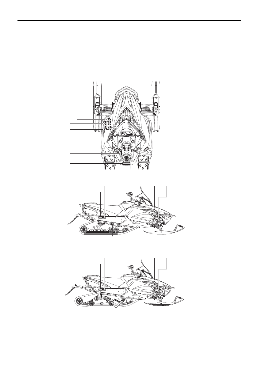
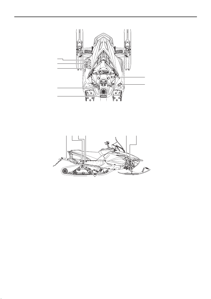
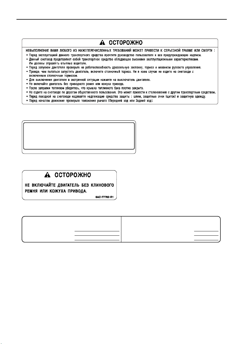
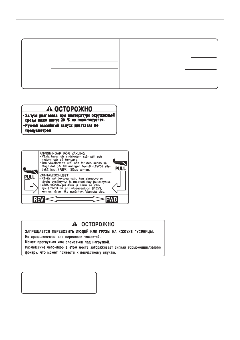
Location of the important labels
RX10PS
79
12
10 118
RX10PXT
7
12
10 11
6
5
4
3
2
1
98
ESU12679
Read and understand all of the labels on your vehicle. They contain important information for
safe and proper operation of your vehicle. Never remove any labels from your vehicle. If a label
becomes difficult to read or comes off, a replacement label is available from your Yamaha dealer.
For EUROPE
1
Page 10
Location of the important labels
DRIVE
1. CHAIN CASE OIL Q’TY
2. CHAIN CASE OIL TYPE
3. TRACK TENSION
* FOR MORE INFO: SEE SERVICE MANUAL FOR THIS
MODEL.
* SPECIFICATIONS SUBJECT TO CHANGE WITHOUT
NOTICE.
ENTRAÎNEMENT
1. CAPACITÉ D’HUILE DU CARTER DE CHAÎNE
2. TYPE D’HUILE DU CARTER DE CHAÎNE
3. FLÈCHE DE LA CHENILLE
* POUR PLUS DE DÉTAIL: VOIR LE MANUEL D’ATELIER
POUR CE MODÈLE.
* LES CARACTÉRISTIQUE TECHNIQUES SONT
SUSCEPTIBLES DE CHANGER SANS NOTIFICATION
PRÉALABLE.
250 cm³ (8.5 oz)
GL-3 75W or 80W
30 ~ 35 mm (1.18 ~ 1.38 in)/100 N (10 kg, 22 lb)
250 cm³
GL-3 75W or 80W
8ES-47578-00
30 ~ 35 mm/100 N (10 kg)
TUNE-UP SPECIFICATIONS
SPECIFICATIONS DE LA MISE AU POINT
8GC-2415E-E0
• PREMIUM UNLEADED GASOLINE.
MIN. OCTANE (PUMP : 91 RON : 95)
• ESSENCE SUPER SANS PLOMB.
INDICE D’OCTANE MIN. (POMPE : 91 RON : 95)
TUNE-UP SPECIFICATIONS
ENGINE
1.SPARK PLUG
2.SPARK PLUG GAP
3.IDLE SPEED
SPECIFICATIONS DE LA MISE AU POINT
MOTEUR
1.TYPE DE BOUGIE
2.ECARTEMENT DES ÉLECTRODES
3.RÉGIME DE RALENTI
CR9EB(NGK)
0.7 ~ 0.8 mm (0.028 ~ 0.031 in)
1600 ± 50 r/min
CR9EB(NGK)
0,7 ~ 0,8 mm
1600 ± 50 r/min
8HG
8HG-1417E-00
1
2
3
4
5
2
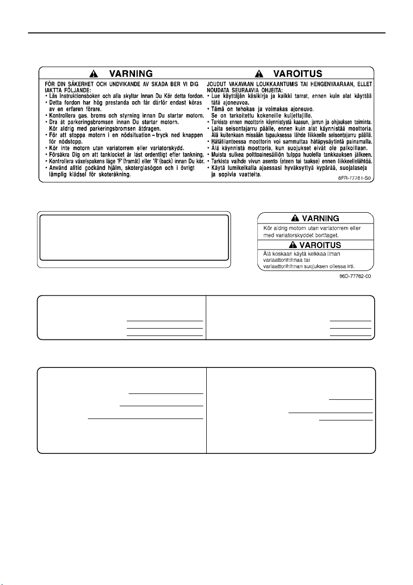
Page 11
Location of the important labels
8HA-77762-S0
8FR-77763-S0
8JC-2156A-00
RX10GT2
111.7 kW 309 kg
8HN-2156A-00
RX10ST2
111.7 kW 317 kg
8 RX10PXT
6
7
8 RX10PS
3
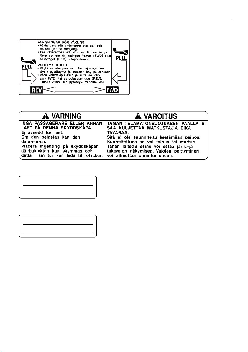
Page 12
Location of the important labels
8FA-S0
8FA-2389C-S0
8AC-2817L-00
YAMAHA MOTOR CO., LTD.
2500 SHINGAI, IWATA, JAPAN
2013
WARNING
This unit contains high pressure nitrogen gas.
Mishandling can cause explosion.
• Read owner’s manual for instructions.
• Do not incinerate, puncture or open.
AVERTISSEMENT
Cette unité contient de I’azote à haute pression.
Une mauvaise manipulation peut entraîner d’explosion.
• Voir le manuel d’utilisateur pour les instructions.
• Ne pas brûler ni perforer ni ouvrir.
8HR-22259-00
WARNING
This unit contains high pressure nitrogen gas.
Mishandling can cause explosion.
• Read owner’s manual for instructions.
• Do not incinerate, puncture or open.
AVERTISSEMENT
Cette unité contient de I’azote à haute pression.
Une mauvaise manipulation peut entraîner d’explosion.
• Voir le manuel d’utilisateur pour les instructions.
• Ne pas brûler ni perforer ni ouvrir.
8JC-22259-00
4AA-22259-40
RX10PXT
11,12
RX10PS
11
12
910
4
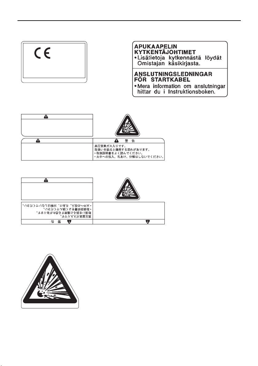
Page 13
Location of the important labels
******
*** kW *** kg
1
23
YAMAHA MOTOR CO., LTD.
2500 SHINGAI, IWATA, JAPAN
****
1
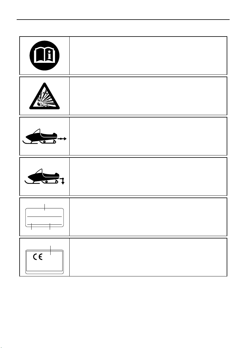
Read the Owner’s manual.
This unit contains high-pressure nitrogen gas.
Mishandling can cause an explosion. Do not incinerate,
puncture or open.
This pictogram shows the sled hitch tow weight limit
(combined weight of the sled and all cargo in the sled).
Overloading can cause loss of control.
Loss of control can result in severe injury or death.
This pictogram shows the sled hitch tongue weight limit
(weight on the sled tongue).
Overloading can cause loss of control.
Loss of control can result in severe injury or death.
1
2
3
Model Name
Max. Power
Mass In Running Order
1
Year of construction
Familiarize yourself with the following pictograms and read the explanatory text.
5
Page 14
Location of the important labels
8
14
12 13
7
5
4
3
2
6
1
119 10
For RUSSIA
6
Page 15
Location of the important labels
8HP-77761-R0
TUNE-UP SPECIFICATIONS
ENGINE
1.SPARK PLUG
2.SPARK PLUG GAP
3.IDLE SPEED
SPECIFICATIONS DE LA MISE AU POINT
MOTEUR
1.TYPE DE BOUGIE
2.ECARTEMENT DES ÉLECTRODES
3.RÉGIME DE RALENTI
CR9EB(NGK)
0.7 ~ 0.8 mm (0.028 ~ 0.031 in)
1600 ± 50 r/min
CR9EB(NGK)
0,7 ~ 0,8 mm
1600 ± 50 r/min
8HG
8HG-1417E-00
8GC-2415E-E0
• PREMIUM UNLEADED GASOLINE.
MIN. OCTANE (PUMP : 91 RON : 95)
• ESSENCE SUPER SANS PLOMB.
INDICE D’OCTANE MIN. (POMPE : 91 RON : 95)
2
3
1
4
7
Page 16
Location of the important labels
5
TUNE-UP SPECIFICATIONS
DRIVE
1. CHAIN CASE OIL Q’TY
2. CHAIN CASE OIL TYPE
3. TRACK TENSION
* FOR MORE INFO: SEE SERVICE MANUAL FOR THIS
MODEL.
* SPECIFICATIONS SUBJECT TO CHANGE WITHOUT
NOTICE.
30 ~ 35 mm (1.18 ~ 1.38 in)/100 N (10 kg, 22 lb)
250 cm³ (8.5 oz)
GL-3 75W or 80W
6
8JE-77764-R0
SPECIFICATIONS DE LA MISE AU POINT
ENTRAÎNEMENT
1. CAPACITÉ D’HUILE DU CARTER DE CHAÎNE
2. TYPE D’HUILE DU CARTER DE CHAÎNE
3. FLÈCHE DE LA CHENILLE
* POUR PLUS DE DÉTAIL: VOIR LE MANUEL D’ATELIER
POUR CE MODÈLE.
* LES CARACTÉRISTIQUE TECHNIQUES SONT
SUSCEPTIBLES DE CHANGER SANS NOTIFICATION
PRÉALABLE.
250 cm³
GL-3 75W or 80W
30 ~ 35 mm/100 N (10 kg)
8ES-47578-00
7
8
9
RX10ST2
111.7 kW 317 kg
8FR-77763-S0
8HA-77762-R0
8HN-2156A-00
8
Page 17
Location of the important labels
8FA-S0
8FA-2389C-S0
4AA-22259-40
8AC-2817L-00
YAMAHA MOTOR CO., LTD.
2500 SHINGAI, IWATA, JAPAN
2013
8HN-2811S-00
10 11
12 13,14
9
Page 18
Safety information
ESU10183
As the vehicle’s owner, you are responsible
for the safe and proper operation of your
snowmobile. When you ride your snowmobile, you must know and use the following for
your safety. Severe injury or death may result
if you ignore any of the following.
Before you operate your snowmobile
● Read the Owner’s Manual and all labels.
Become familiar with all of the operating
controls and their function. Consult a
Yamaha dealer about any control or function you do not understand.
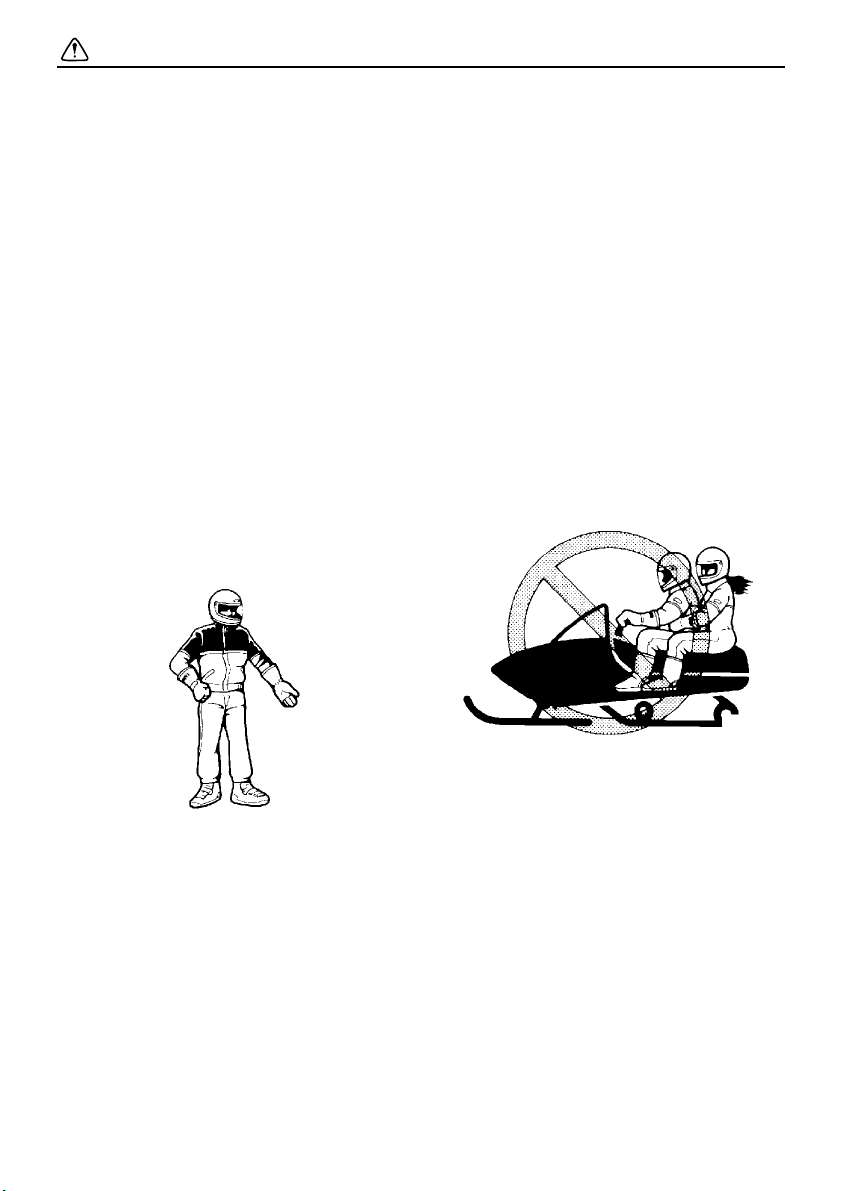
● Wear protective clothing. Wear an ap-
proved helmet, and a face shield or goggles. Also, wear a good quality snowmobile
suit, boots, and a pair of gloves or mittens
that will permit use of your thumbs and fingers for operation of the controls.
creases the possibility of an accident or
equipment damage. See page 39 for a list
of pre-operation checks.
● Apply the parking brake before starting the
engine. Never drive the snowmobile with
the parking brake applied. This may overheat the brake disc and reduce braking ability.
While using your snowmobile
● This snowmobile was not manufactured for
use on public streets, roads, or highways.
Such use is prohibited by law, and you
could collide with another vehicle.
● This snowmobile is designed to carry the
OPERATOR ONLY. Passengers are prohibited. Carrying a passenger can cause
loss of control.
● Do not operate the snowmobile after or
while drinking alcohol or taking drugs. Your
ability to operate the snowmobile is reduced by the influence of alcohol or drugs.
Prepare your snowmobile
● Perform the pre-operation checks each
time you use the vehicle to make sure it is
in safe operating condition. Failure to inspect or maintain the vehicle properly in-
10
● Be careful where you ride. There may be
obstacles hidden beneath the snow. Stay
on established trails to minimize your exposure to hazards. Ride slowly and cautiously
when you ride off of established trails. Hitting a rock or stump, or running into wires
could cause an accident and injury.
● This snowmobile is not designed for use on
surfaces other than snow or ice. Use on dirt,
sand, grass, rocks, or bare pavement may
cause loss of control and may damage the
snowmobile.
Page 19

Safety information
● Always ride with other snowmobilers when
going on a ride. You may need help if you
run out of fuel, have an accident, or damage
your snowmobile.
● Many surfaces such as ice and hardpacked
snow require much longer stopping distances. Be alert, plan ahead and begin decelerating early. The best braking method on
most surfaces is to release the throttle and
apply the brake gently—not suddenly.
Avoid carbon monoxide poisoning
All engine exhaust contains carbon monoxide, a deadly gas. Breathing carbon monoxide
can cause headaches, dizziness, drowsiness,
nausea, confusion, and eventually death.
Carbon monoxide is a colorless, odorless,
tasteless gas which may be present even if
you do not see or smell any engine exhaust.
Deadly levels of carbon monoxide can collect
rapidly and you can quickly be overcome and
be unable to save yourself. Also, deadly levels of carbon monoxide can linger for hours or
days in enclosed or poorly-ventilated areas. If
you experience any symptoms of carbon
monoxide poisoning, leave the area immediately, get fresh air, and SEEK MEDICAL
TREATMENT.
● Do not run the engine indoors. Even if you
try to ventilate engine exhaust with fans or
open windows and doors, carbon monoxide
can rapidly reach dangerous levels.
● Do not run the engine in poorly ventilated or
partially enclosed areas such as barns, garages, or carports.
● Do not run the engine outdoors where en-
gine exhaust can be drawn into a building
through openings such as windows and
doors.
Genuine Yamaha Accessories
Choosing accessories for your snowmobile is
an important decision. Genuine Yamaha Accessories, which are available only from a
Yamaha dealer, have been designed, tested,
and approved by Yamaha for use on your
snowmobile. Many companies with no connection to Yamaha manufacture parts and accessories or offer other modifications for
Yamaha vehicles. Yamaha is not in a position
to test the products that these aftermarket
companies produce. Therefore, Yamaha can
neither endorse nor recommend the use of
accessories not sold by Yamaha or modifications not specifically recommended by
Yamaha, even if sold and installed by a
Yamaha dealer.
Maintenance and storage
● When laying the snowmobile on its side for
maintenance, use a suitable stand to keep
it in a stable and level position.
● Do not leave the snowmobile on its left side
for an extended period of time. Fuel may
leak out from the fuel breather hose.
● Do not allow anyone to stand behind the
snowmobile when starting, inspecting, or
adjusting the snowmobile. A broken track,
track fittings, or debris thrown by the track
could be dangerous to the operator or bystanders.
● Modifications made to the snowmobile not
approved by Yamaha, or the removal of
original equipment may render your snowmobile unsafe for use, which may cause severe personal injury. Modifications may
also make the snowmobile illegal to use.
● Never store the snowmobile with fuel in the
fuel tank inside a building where ignition
sources are present such as hot water and
space heaters, an open flame, sparks,
11
Page 20

Safety information
clothes dryers, and the like. Allow the engine to cool off before storing the snowmobile in an enclosed space.
12
Page 21
ESU10261
Description
RX10PS
1,2,3,4,5 6 7,8,9 10,11 12
131415
RX10PXT
1,2,3,4,5 6 7,8,9 10,11 12
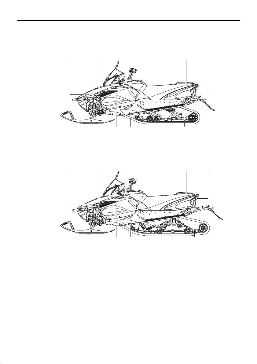
1. Battery
2. Main fuse
3. EPS fuse
4. Fuel injection system fuse
5. Air filter
6. Oil filler cap
7. Fuse box
8. Coolant reservoir
9. Coolant recovery tank
10. Tool kit
11. Storage compartment
12. Tail/brake light
13. Slide rail suspension
131415
14. Drive track
15. V-belt holder
13
Page 22
Description
TIP
1 6 72 3
8910
4
11
5
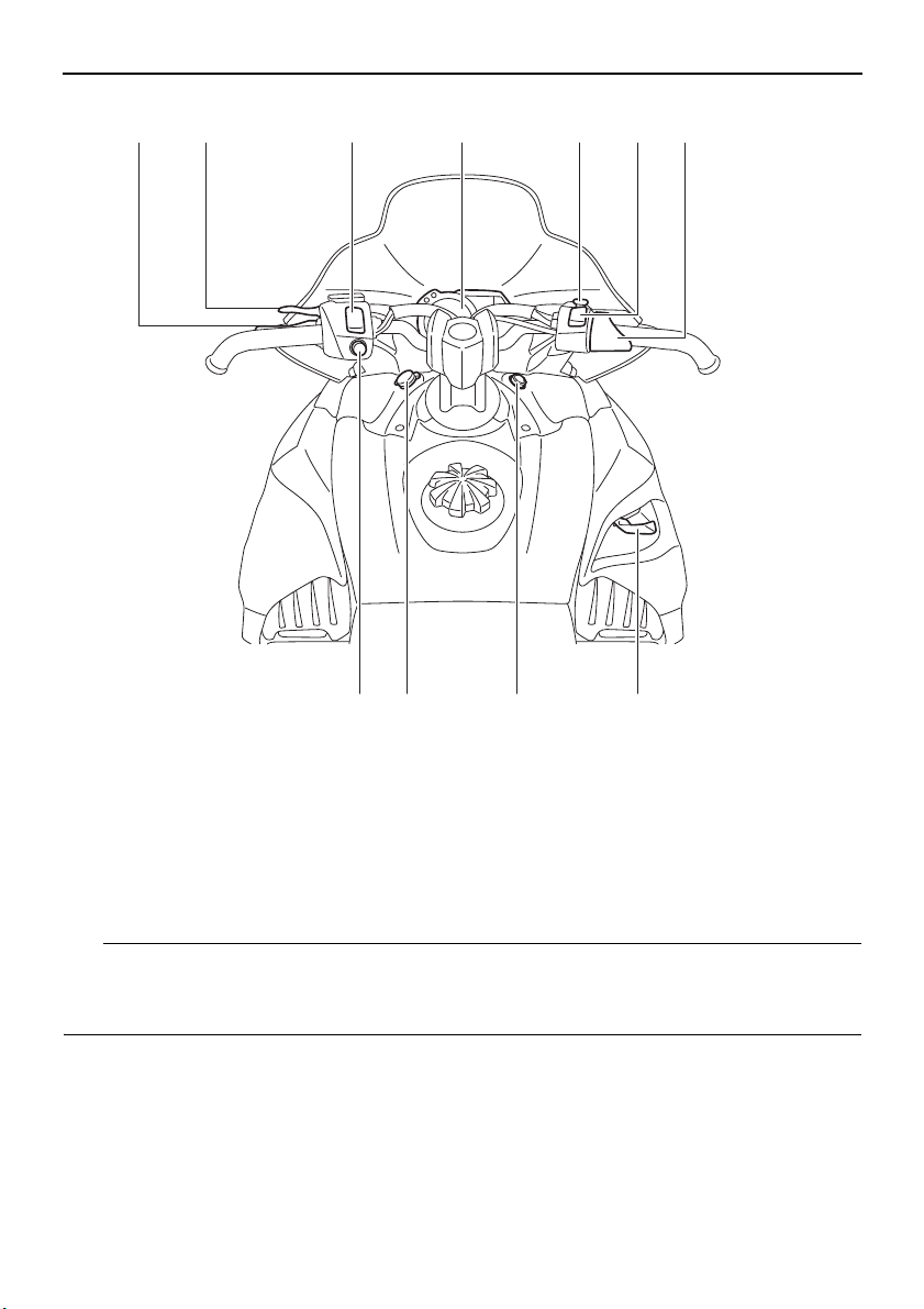
1. Brake lever
2. Parking brake lever
3. Grip warmer adjusting switch
4. Multi-function meter unit
5. Engine stop switch
6. Thumb warmer adjusting switch
● The snowmobile you have purchased may differ slightly from those shown in the figures of
this manual.
● Design and specifications are subjected to change without notice.
7. Throttle lever
8. Shift lever
9. Main switch
10. Auxiliary DC jack
11. Headlight beam switch
14
Page 23
Control functions
TIP
WARNING
13
2
ESU10292
Main switch
The main switch controls the ignition and
lighting systems. The various positions are
described below.
1. Off
2. On
3. Start
Off
The ignition circuit is switched off.
The key can be removed only in this position.
On
The ignition circuit is switched on.
Start
The starting circuit is switched on.
The starter motor cranks the engine.
NOTICE: Release the switch immediately
after the engine starts.
The headlights and taillight come on after the
engine is started.
ESU10312
[ECS00021]
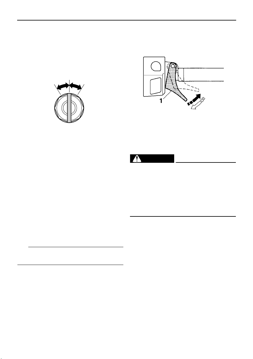
Throttle lever
Once the engine is running cleanly, squeezing the throttle lever will increase the engine
speed and cause engagement of the drive
train. Regulate the speed of the snowmobile
by varying the throttle position. Because the
throttle is spring-loaded, the snowmobile will
decelerate, and the engine will return to idle
when it is released.
1. Throttle lever
ESU13242
Throttle override system (T.O.R.S.)
EWS00041
If the T.O.R.S. is activated, make sure that
the cause of the malfunction has been corrected and that the engine can be operated
without a problem before restarting the
engine. Continuing to operate with a malfunction could cause loss of control or
damage.
If the throttle valves or throttle cable malfunctions during operation, the T.O.R.S. will be activated when the throttle lever is released.
The T.O.R.S. is designed to override the fuel
injection and limit the engine speed to less
than the clutch engagement speed if the throttle valves fail to return to the idle position
when the throttle lever is released. (See page
93 for the clutch engagement speed.)
15
Page 24
Control functions
TIP
Malfunc-
tion
T. O. R . S .
will be ac-
tivated.
Throttle
lever
Throttle
valve
T.O. R.S.
Idling Riding
Released Squeezed Released
Closed Open Open
Engine
runs
properly.
Engine
runs
properly.
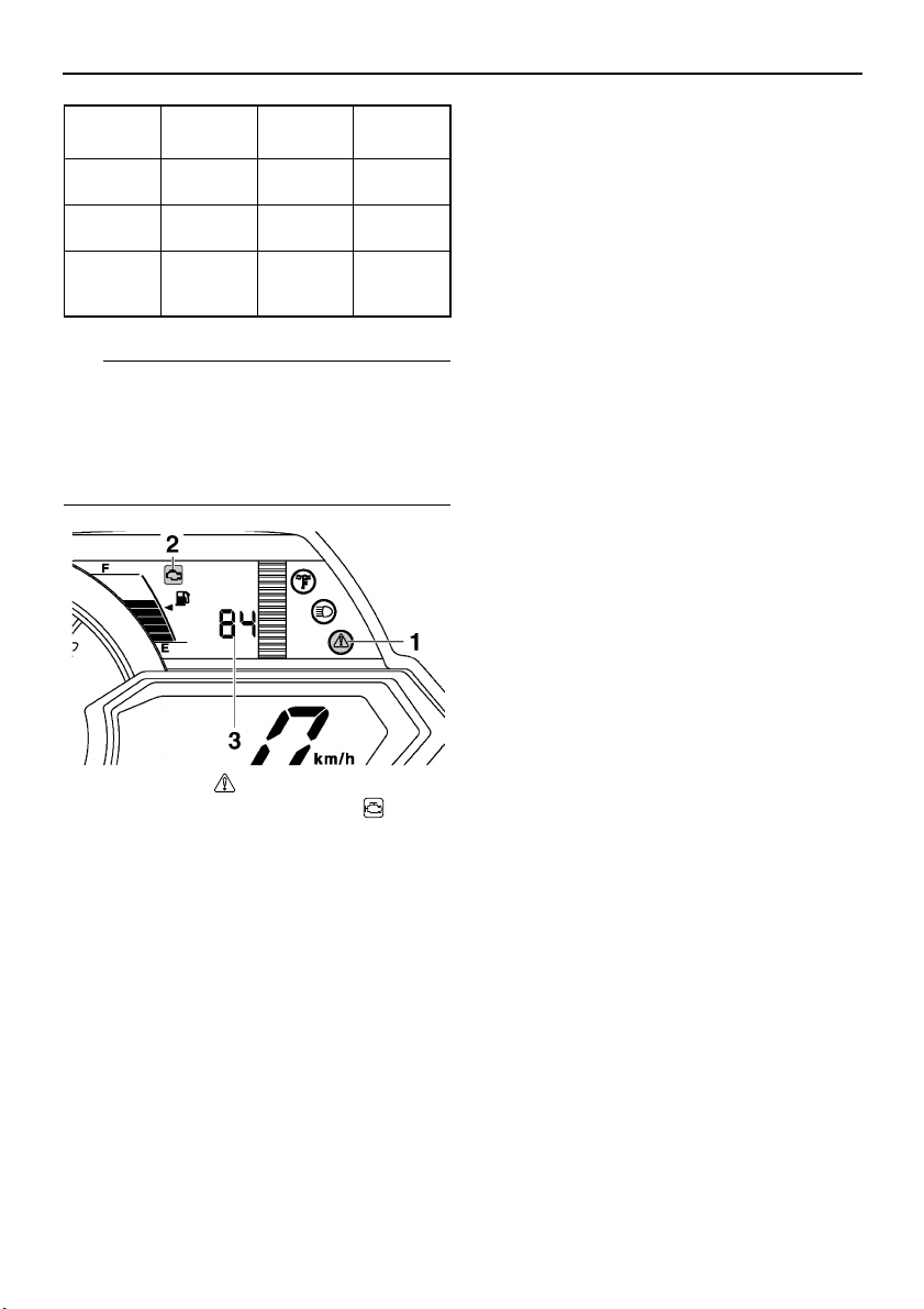
If the T.O.R.S. is activated, the warning light
and engine trouble warning indicator flash,
and the two-digit code “84” displays in the
meter display. If this occurs, have a Yamaha
dealer check the system as soon as possible.
● an oil change tripmeter (which shows the
distance traveled since the periodic oil
change interval was reached)
● a barometer (which shows the ambient
barometric pressure)
● a clock
● warning indicators (which show engine
trouble, coolant temperature, fuel level, oil
level, and oil pressure warnings)
● indicator lights (which show high beam and
low coolant temperature conditions)
● a warning light (which shows warnings to-
gether with the warning indicators)
● a fuel meter (which shows the fuel remain-
ing in the fuel tank)
● a grip/thumb warmer level indicator (which
shows the grip warmer level or the thumb
warmer level)
● a display brightness control function
● an electric power steering warning indicator
When the key is turned to the on position, the
tachometer needle makes one sweep, and
the low coolant temperature indicator light,
the warning light, and all segments of the
meter unit display come on and go off.
1. Warning light “ ”
2. Engine trouble warning indicator “ ”
3. Two-digit code “84”
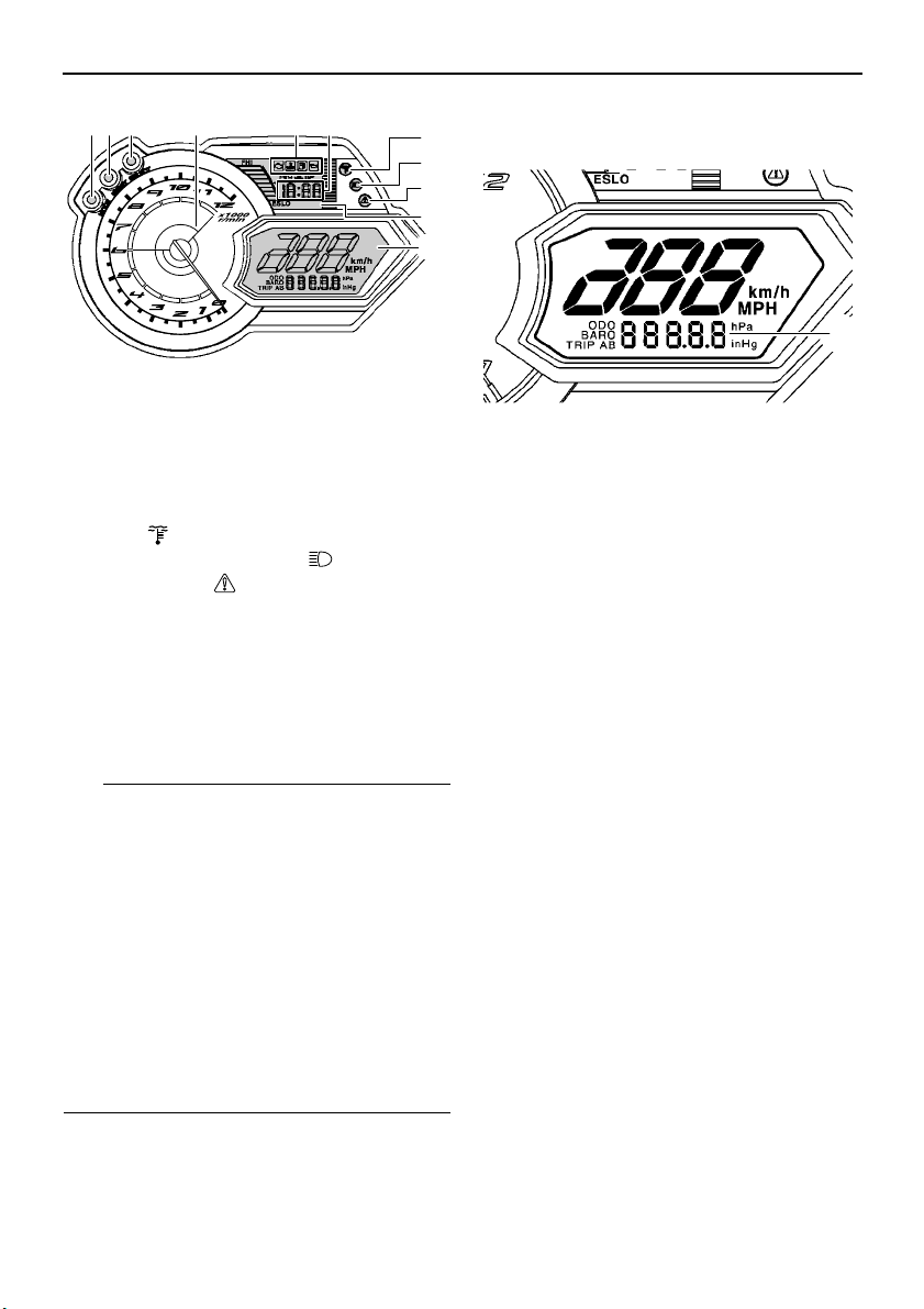
ESU10368
Multi-function meter unit
The multi-function meter unit is equipped with
the following:
● a digital speedometer
● a tachometer
● an odometer
● two tripmeters (which show the distance
traveled since they were last set to zero)
● a fuel reserve tripmeter (which shows the
distance traveled since the fuel level warning indicator and the warning light came on)
16
Page 25
TIP
1. “MODE” button
EPS
12 3 5 6
7
8
11
4
9
10
1
2. “RESET” button
3. “SELECT” button
4. Tachometer
5. Warning indicators
6. Clock
7. Low coolant temperature indicator
light “ ”
8. High beam indicator light “ ”
9. Warning light “ ”
10. Electric power steering warning indicator
“EPS”
11. Meter display
The grip warmer level is initially displayed for
5 seconds, then the display switches to the
fuel meter.
● To switch the speedometer, odometer, and
tripmeter displays between kilometers and
miles, select the odometer mode “ODO”,
and then push the “SELECT” button for at
least 10 seconds while the snowmobile is
stopped.
● To switch the barometer display between
hectopascal “hPa” and inches of mercury
“inHg”, select the barometer mode “BARO”,
and then push the “SELECT” button for at
least 3 seconds while the snowmobile is
stopped.
Control functions
Odometer, tripmeter, and barometer
modes
1. Odometer/tripmeter/barometer
Pushing the “SELECT” button switches the
display between the odometer mode “ODO”,
tripmeter modes “TRIP A” and “TRIP B”, and
barometer mode “BARO” in the following order:
ODO → TRIP A → TRIP B → BARO → ODO
If the fuel level warning indicator and the
warning light come on (see page 20), the
odometer display will automatically change to
the fuel reserve tripmeter mode “TRIP F” and
start counting the distance traveled from that
point. In that case, push the “SELECT” button
to switch the display between the various tripmeter and odometer modes in the following
order:
TRIP F → ODO → TRIP A → TRIP B →
BARO →TRIP F
To reset a tripmeter, select it by pushing the
“SELECT” button, and then push the “RESET” button for at least 1 second. If you do not
reset the fuel reserve tripmeter manually, it
will reset itself automatically, and the display
will return to the prior mode after the snowmobile has been refueled and traveled 5 km (3
mi).
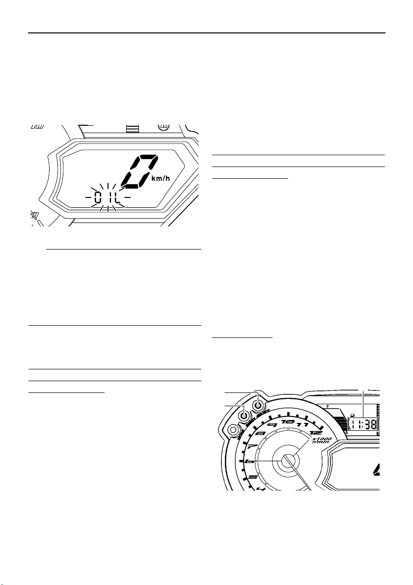
Oil change tripmeter
When the periodic oil change interval is
reached at the initial 800 km (500 mi), then at
every 4000 km (2500 mi) thereafter, the oil
17
Page 26
Control functions
TIP
2
1
3
change tripmeter and “OIL” flash alternately in
the odometer display, and the tripmeter starts
counting the distance traveled from that point.
When this occurs, change the engine oil as
soon as possible. (See page 60 for the oil
change procedure.)
E LO
● The oil change tripmeter will flash only
when the snowmobile is stopped.
● To return to the previous display mode,
push the “SELECT” button. To display the
oil change tripmeter again, turn the key to
the off position, then back to the on position.
After changing the engine oil, reset the oil
change tripmeter as follows.
To reset the oil change tripmeter (when the
engine oil was changed after the oil change
tripmeter appeared)
1. To display the oil change tripmeter, turn
the key to the on position.
2. Push the “RESET” button for at least 1
second while the oil change tripmeter and
“OIL” are flashing alternately in the odometer display. The distance traveled since
the last oil change and “OIL” will flash alternately in the odometer display.
3. Push the “RESET” button for approximately 3 seconds. “00000” and “OIL” will
flash alternately in the odometer display 3
times, and then the display will return to
the previous display mode.
If the engine oil is changed before the oil
change tripmeter appears in the display (i.e.,
before the periodic oil change interval has
been reached), the tripmeter must be reset after the oil change for the next periodic oil
change to be indicated at the correct time.
In that case, reset the oil change tripmeter as
follows.
To reset the oil change tripmeter (when the
engine oil was changed before the oil change
tripmeter appeared)
1. Push the “SELECT” button until “ODO” is
displayed, and then push the “RESET”
button for at least 1 second. The distance
traveled since the last oil change and
“OIL” will flash alternately in the odometer
display.
2. Push the “RESET” button for approximately 3 seconds. “00000” and “OIL” will
flash alternately in the odometer display 3
times, and then the display will return to
the previous display mode.
Clock
To set the clock
1. Push the “SELECT” button and “RESET”
button simultaneously until the hour digits
start flashing.
1. “SELECT” button
2. “RESET” button
3. Clock
18
Page 27
Control functions
TIP
1
2
3
2. Push the “RESET” button to change the
hour setting, and then push the “SELECT” button. The minute digits will start
flashing.
3. Push the “RESET” button to change the
minute setting, and then push the “SELECT” button. The clock starts when the
“SELECT” button is released.
The clock must be set again when the battery
is disconnected.
Display brightness control
This function allows you to adjust the brightness of the meter display to suit the outdoor
lighting conditions.
To adjust the display brightness
1. Turn the key to the off position.
2. Push and hold down the “SELECT” button.
ESU10411
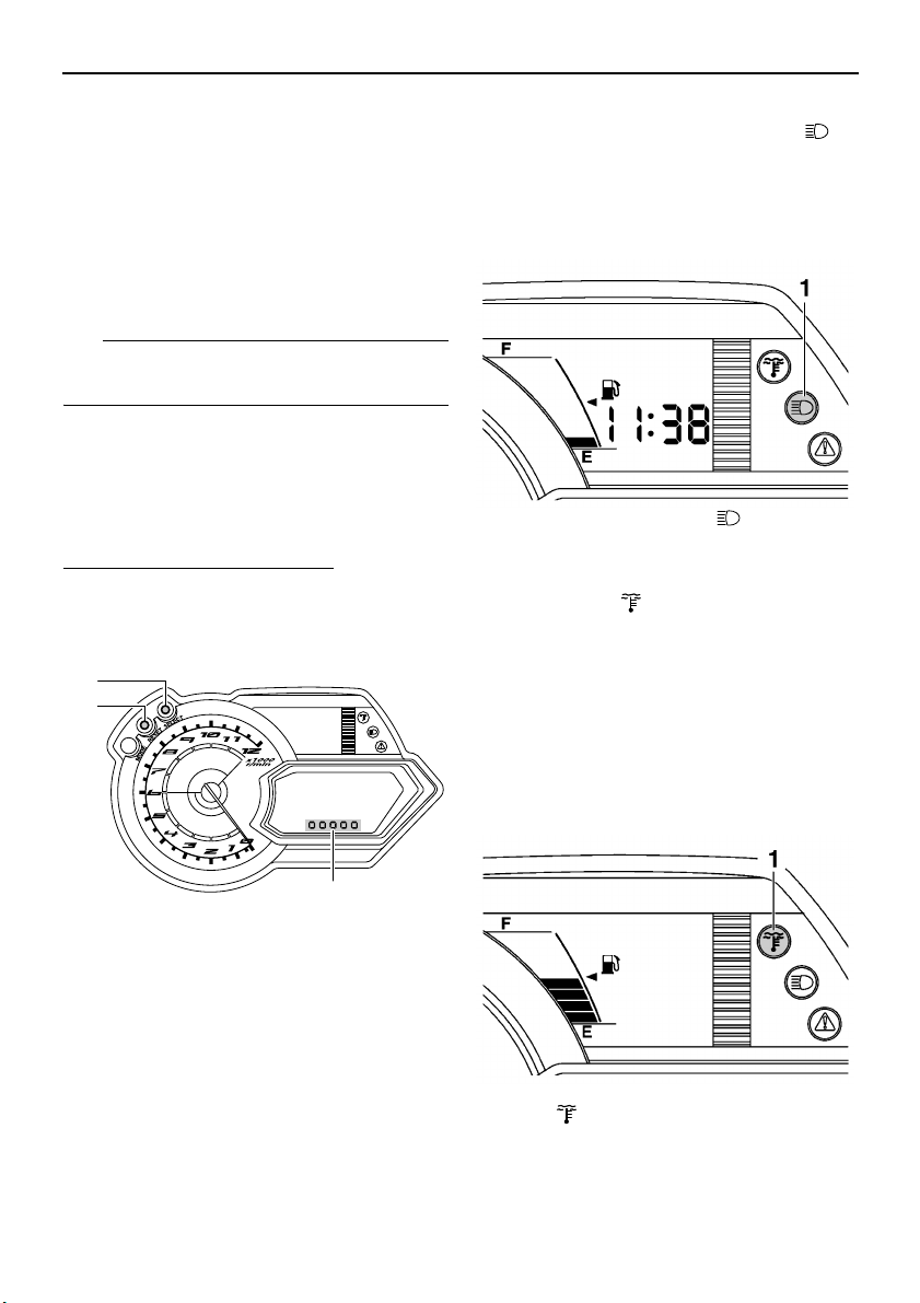
High beam indicator light “ ”
The high beam indicator light comes on when
the high beams of the headlights are switched
on. (See page 24 for headlight beam switch
operation.)
1. High beam indicator light “ ”
ESU10473
Low coolant temperature indicator light “ ”
The low coolant temperature indicator light
comes on when the coolant temperature is
low and informs the rider that the snowmobile
should be warmed up. After the engine is
started, warm it up until the indicator light
goes off.
The snowmobile can be operated normally after the indicator light goes off.
1. “SELECT” button
2. “RESET” button
3. Display brightness level
3. Turn the key to the on position, and then,
after 5 seconds, release the “SELECT”
button.
4. Push the “RESET” button to select the
desired display brightness level, and then
push the “SELECT” button. The normal
display returns when the “SELECT” button is released.
1. Low coolant temperature indicator
light “ ”
19
Page 28
Control functions
TIP
TIP
Drive the snowmobile at low speeds when the
low coolant temperature indicator light is on. If
the engine speed is too high, maximum engine speed is reduced to protect the engine.
ESU10427
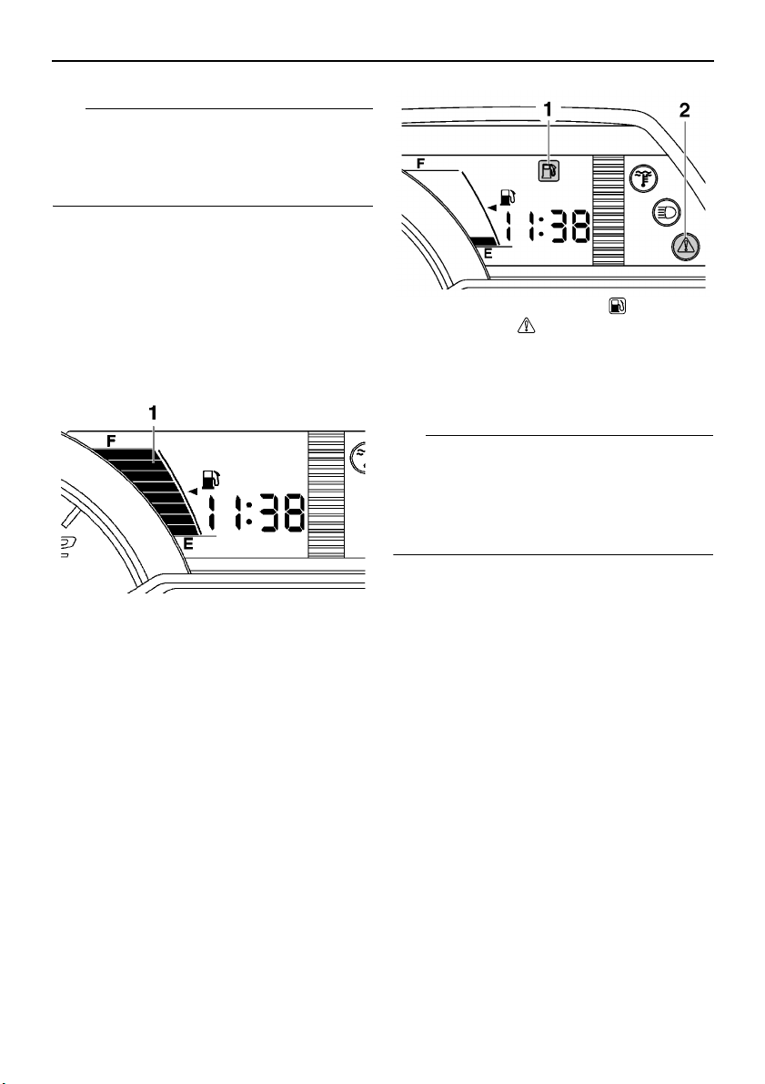
Fuel meter and grip/thumb warmer level indicator
The fuel meter and grip/thumb warmer level
indicator have eight segments which show
the amount of fuel remaining in the fuel tank,
the grip warmer level, or the thumb warmer
level.
1. Fuel level warning indicator “ ”
2. Warning light “ ”
If the fuel level warning indicator and the
warning light come on, refuel as soon as possible.
The snowmobile must be stopped on a level
surface to obtain an accurate fuel meter reading, since the reading changes according to
the movement and inclination of the snowmobile.
1. Fuel meter and grip/thumb warmer level indicator
Fuel meter
The display segments of the fuel meter disappear towards “E” (Empty) as the fuel level decreases. When only one segment is left near
“E”, the fuel level warning indicator and the
warning light come on.
20
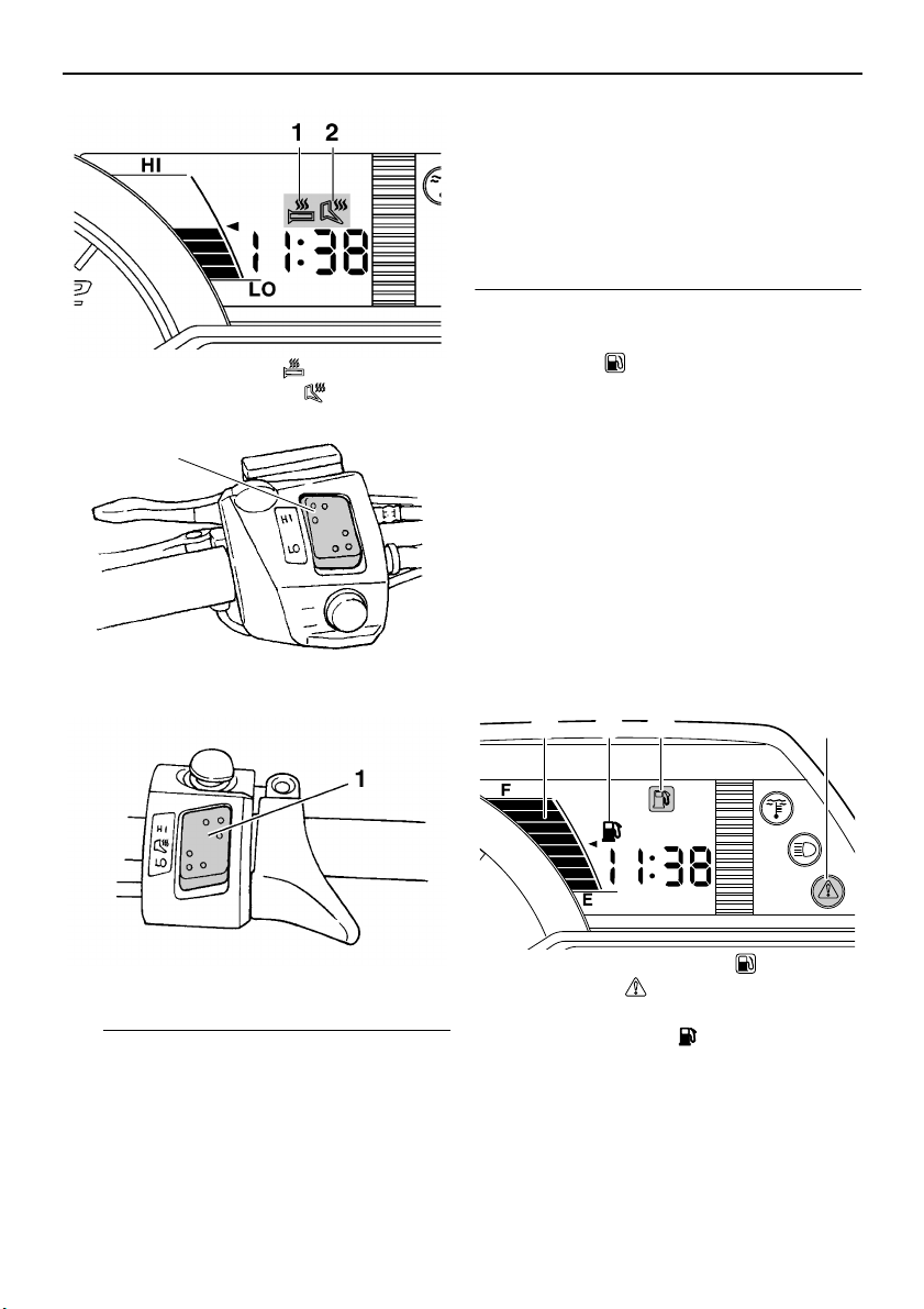
Grip/thumb warmer level indicator
When the grip warmer adjusting switch is
pressed, the grip warmer indicator comes on
and the display switches to the grip warmer
level.
When the thumb warmer adjusting switch is
pressed, the thumb warmer indicator comes
on and the display switches to the thumb
warmer level.
See “Grip/thumb warmer adjusting switch” on
page 24 for detailed information.
Page 29
TIP
1. Grip warmer indicator “ ”
1
31 24
2. Thumb warmer indicator “ ”
1. Grip warmer adjusting switch
Control functions
maximum level. The bottom segment of the
grip/thumb warmer level indicator flashes
once when the grip/thumb warmer adjustment reaches the minimum level.
● When the engine is started, the grip/thumb
warmer levels are set to the levels selected
when the engine was last stopped.
ESU13252
Fuel level warning
indicator “ ”
The fuel level warning indicator and the warning light come on when the fuel level is low.
(See page 20 for details.)
The fuel level warning indicator, the warning
light, the fuel meter indicator, and all segments of the fuel meter start to flash when a
malfunctioning sensor, disconnected coupler,
broken lead, or short circuit is detected by the
self-diagnosis device of the snowmobile to
warn the rider of any of the above problems.
If this occurs, have a Yamaha dealer inspect
the snowmobile as soon as possible.
1. Thumb warmer adjusting switch
● The grip/thumb warmer level is displayed
for 5 seconds after releasing the grip/thumb
warmer adjusting switch, then the display
switches to the fuel meter.
● The top segment of the grip/thumb warmer
level indicator flashes once when the
grip/thumb warmer adjustment reaches the
1. Fuel level warning indicator “ ”
2. Warning light “ ”
3. Fuel meter
4. Fuel meter indicator “ ”
21
Page 30
Control functions
TIP
1
2
ESU13991
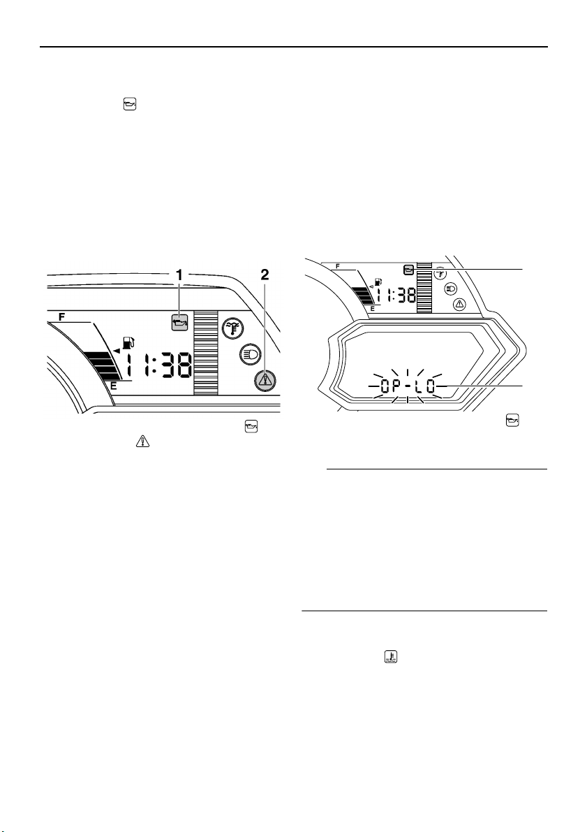
Oil level/pressure warning
indicator “ ”
The oil level/pressure warning indicator has
two functions. The warning indicator comes
on when the engine oil level is low and when
the engine oil pressure is low. The functions
are explained in the following sections.
Oil level warning
The warning indicator and the warning light
come on when the engine oil level is low.
1. Oil level/pressure warning indicator “ ”
2. Warning light “ ”
If the warning indicator and the warning light
come on, place the snowmobile on a level
surface and allow it to idle for one minute.
If the warning indicator and the warning light
go off, the engine oil level is sufficient, however it is getting low. Add engine oil as soon as
possible.
If the warning indicator and the warning light
do not go off, check the engine oil level in the
oil tank (see page 60 for engine oil level
checking procedures), and add engine oil if
necessary.
If the warning indicator and the warning light
still remain on, have a Yamaha dealer check
the snowmobile.
Oil pressure warning
The warning indicator comes on and “OP-LO”
(oil pressure low) appears in the odometer
display if the engine oil pressure is low when
the engine is started. At the same time, the
engine speed is limited to less than the clutch
engagement speed until the warning indicator
goes off.
If the engine oil pressure remains low for one
minute, the engine stops. If this occurs, have
a Yamaha dealer check the snowmobile.
1. Oil level/pressure warning indicator “ ”
2. “OP-LO” (oil pressure low)
If there is no engine oil in the oil passages
when the engine is started, such as after the
engine oil is changed, the warning indicator
may come on and “OP-LO” may appear in the
odometer display for a few seconds until the
oil circulates through the engine. The snowmobile can be operated normally after the
warning indicator goes off.
ESU10513
Coolant temperature warning
indicator “ ”
If the engine overheats, the coolant temperature warning indicator and the warning light
come on. When this occurs, stop the engine
immediately and allow the engine to cool
22
Page 31

down, and then check the coolant level in the
NOTICE
TIP
32 1
coolant reservoir. (See page 64 for checking
procedures.)
1. Coolant temperature warning indicator “ ”
2. Warning light “ ”
ECS00041
Do not continue to operate the engine if it
is overheating.
ESU13812
Electric power steering warning indicator “EPS”
The electric power steering warning indicator
comes on when the key is turned to the on position, and then goes off once the engine is
started. If the warning indicator remains on or
comes on after the engine is started, the EPS
system may not be working correctly. When
this occurs, have a Yamaha dealer check the
EPS system.
1. Electric power steering warning indicator
“EPS”
Control functions
If the steering load is too heavy (i.e., excessive steering use when the snowmobile is
traveling at a slow speed), the power assist is
reduced to protect the EPS motor from overheating.
ESU13365
Self-diagnosis device
This model is equipped with a self-diagnosis
device for various electrical circuits.
If a problem is detected in any of those circuits, the warning light and the engine trouble
warning indicator flash, and an error code displays in the meter display. Note the error
code, and then have a Yamaha dealer inspect
the snowmobile as soon as possible.
NOTICE: Do not continue to operate the
engine longer than necessary if there is an
error code to avoid possible engine damage.
[ECS00820]
1. Warning light “ ”
2. Engine trouble warning indicator “ ”
3. Error code display
ESU10531
Engine stop switch “ ”
The engine stop switch is used to stop the engine in an emergency. Simply push the stop
switch to stop the engine. To start the engine,
pull the stop switch and proceed with starting
the engine. (See page 41 for engine starting
procedures.)
23
Page 32

Control functions
TIP
1
1. Engine stop switch “ ”
During the first few rides, practice using the
stop switch so that you can react quickly in an
emergency.
ESU10661
Headlight beam switch
“LIGHTS”
Push the headlight beam switch to change the
headlight to high beam “HI” or to low beam
“LO”.
1. Headlight beam switch “LIGHTS”
2. High beam “HI”
3. Low beam “LO”
ESU12654
Grip/thumb warmer adjusting switch
The grip warmer adjusting switch and the
thumb warmer adjusting switch control the
electrically heated handlebar grips and throttle lever respectively.
1. Grip warmer adjusting switch
1. Thumb warmer adjusting switch
To raise the temperature
To raise the temperature, press the respective switch to “HI”.
To lower the temperature
To lower the temperature, press the respective switch to “LO”.
See “Fuel meter and grip/thumb warmer level
indicator” on page 20 for detailed information.
ESU10696
Auxiliary DC jack
The auxiliary DC jack is located in the front
panel and can be used for accessories.
The auxiliary DC jack can only be used if the
engine is running.
To use the auxiliary DC jack
1. Start the engine.
24
Page 33

2. Open the auxiliary DC jack cap, and then
NOTICE
TIP
2
1
insert the accessory power plug into the
jack.
Control functions
1. Brake lever
1. Auxiliary DC jack cap
2. Auxiliary DC jack
3. After using the auxiliary DC jack, be sure
to remove the accessory power plug from
the jack and to close the auxiliary DC jack
cap.
ECS00122
● To avoid circuit overload and a possible
fuse blowing, do not use accessories requiring more than the maximum rated
capacity for the auxiliary DC jack. (See
page 82 for the specified fuse amperage.)
● Do not use an automotive cigarette light-
er or other accessory with a plug that
gets hot because the jack can be damaged.
Maximum rated capacity:
DC 12 V, 2.5 A (30 W)
ESU13523
Brake lever
The snowmobile is stopped by braking the entire drive system.
Squeeze the brake lever towards the handlebar grip to stop the snowmobile.
When the brake lever is squeezed, the brake
light comes on.
The brake lever is equipped with a position
adjuster.
To adjust the brake lever position
1. Loosen the locknut.
2. While lightly pushing the brake lever in direction (a), turn the adjusting bolt to set
the brake lever to the desired position.
1. Locknut
2. Adjusting bolt
3. Tighten the locknut securely after adjusting the brake lever position.
ESU10581
Parking brake lever
When parking the snowmobile or starting the
engine, apply the parking brake by moving the
parking brake lever to the left.
25
Page 34

Control functions
NOTICE
WARNING
1
1
2
3
3
2
1
1. Parking brake lever
To release the parking brake, move the parking brake lever to the right.
ESU10593
Shift lever
The shift lever is used to put the snowmobile
into forward or reverse. After coming to a
complete stop, pull the shift lever out, slide it
to “FWD” or to “REV” until it stops, and then
release it.
1. Pull out.
2. Slide to “FWD” (forward).
3. Release.
1. Pull out.
2. Slide to “REV” (reverse).
3. Release.
ECS00072
Do not use the shift lever while the snowmobile is moving, otherwise the drive train
could be damaged.
ESU13314
Drive guard
EWS00402
26
1. Shift lever
● Coming in contact with the rotating V-
belt or clutch parts can cause severe injury or death. Never run the engine with
the drive guard removed.
● Make sure that the drive guard is in-
stalled securely before operating the
snowmobile to protect against severe
Page 35

injury or death from a broken V-belt or
NOTICE
1
2
1
2
1
other part should it come off the snowmobile while it is in operation.
ECS00930
● Never run the engine with the V-belt re-
moved. Clutch components can be damaged.
● Be careful not to scratch the windshield
when removing or installing the drive
guard.
The drive guard is designed to protect the Vbelt clutch and V-belt in case parts break or
come loose.
The drive guard is located behind the left side
cover. (See page 53 for removal procedures.)
To remove the drive guard
1. Pull out the drive guard locking pin from
the drive guard rear holder.
Control functions
To install the drive guard
1. Fit the front slots in the drive guard over
the projections on the drive guard front
holder.
1. Drive guard
2. Drive guard locking pin
2. Lift up the rear of the drive guard as
shown, and then pull the guard rearward
to remove it.
1. Drive guard
2. Align the slots in the rear of the drive
guard with the projections on the drive
guard rear holder, and then insert the
drive guard locking pin into the holder as
shown.
1. Drive guard
2. Drive guard locking pin
27
Page 36

Control functions
NOTICE
WARNING
1
1
2
ESU10761
V-belt holders
Keep a spare V-belt for emergency use by
placing it into the V-belt holders provided.
1. V-belt holder
ECS00180
Make sure that the V-belt is installed securely in the holders.
ESU10811
Storage compartment
The storage compartment is located behind
the seat. Use the storage compartment to
store the tool kit, manuals, spare parts, or other small items.
To open the storage compartment
Turn the fastener 1/2 turn in either direction,
and then fold the storage compartment cover
up.
To close the storage compartment
Fold the storage compartment cover down,
and then turn the fastener to the original position.
ESU10637
Fuel
EWS00071
Gasoline and gasoline vapors are extremely flammable. To avoid fires and explosions and to reduce the risk of injury
when refueling, follow these instructions.
Make sure there is sufficient gasoline in the
tank.
1. Before refueling, turn off the engine and
be sure that nobody is on the snowmobile. Never refuel while smoking, or while
in the vicinity of sparks, open flames, or
other sources of ignition such as the pilot
lights of water heaters and clothes dryers.
2. Do not overfill the fuel tank. Stop filling
when the fuel reaches the bottom of the
filler tube. Because fuel expands when it
heats up, heat from the engine or the sun
can cause fuel to spill out of the fuel tank.
28
1. Fastener
2. Storage compartment
Page 37

WARNING
NOTICE
1. Filler tube
2. Maximum fuel level
3. Wipe up any spilled fuel immediately.
4. Be sure the fuel tank cap is closed securely by turning it clockwise.
EWS00680
Gasoline is poisonous and can cause injury or death. Handle gasoline with care.
Never siphon gasoline by mouth. If you
should swallow some gasoline or inhale a
lot of gasoline vapor, or get some gasoline
in your eyes, see your doctor immediately.
If gasoline spills on your skin, wash with
soap and water. If gasoline spills on your
clothing, change your clothes.
Control functions
Recommended fuel:
RX10PS Min 98 RON UNLEADED
GASOLINE ONLY
RX10PXT Min 95 RON UNLEADED
GASOLINE ONLY (RUS)
RX10PXT Min 98 RON UNLEADED
GASOLINE ONLY (FIN)(SWE)
Fuel tank capacity:
34.6 L (9.14 US gal, 7.61 Imp.gal)
Your Yamaha engine has been designed to
use unleaded gasoline with a research octane
number of 98 or higher. (For Russia, premium
unleaded gasoline with a pump octane number [(R+M)/2] of 91 or higher, or a research
octane number of 95 or higher.)
If the recommended fuel is not used, the engine may not perform as it should.
ECS00094
● Make sure that snow or ice does not en-
ter the fuel tank when refueling.
● The fuel tank should be filled with the
recommended gasoline. The use of other gasoline will cause severe damage to
internal engine parts, such as the valves
and piston rings, as well as to the exhaust system.
ESU14001
Suspension
The suspension can be adjusted to suit rider
preference. Softer settings, for example, may
provide greater rider comfort, while harder
settings may allow more precise handling and
control over certain types of terrain or riding
conditions.
If you are not familiar with suspension adjustments, have a Yamaha dealer make these
adjustments.
29
Page 38

Control functions
WARNING
TIP
WARNING
TIP
(a)
(b)
1
3
2
EWS00151
Read and understand the following information before handling shock absorbers
that contain highly pressurized nitrogen
gas.
● Do not tamper with or attempt to open
the cylinder assemblies.
● Do not subject the shock absorbers to
an open flame or other high heat source.
This may cause the unit to explode due
to excessive gas pressure.
● Do not deform or damage the cylinders
in any way. Cylinder damage will result
in poor damping performance.
● Do not dispose of a damaged or worn
out shock absorber yourself. Take the
shock absorber to a Yamaha dealer for
any service.
Use the special wrench included in the owner’s tool kit to make the suspension adjustments. If the tool kit for your model does not
include the special wrench, the special
wrench can be obtained at a Yamaha dealer.
ESU10894
Adjusting the spring preload of the
front shock absorbers (RX10PXT)
EWS00720
The spring preload of the left and right
shock absorbers must be adjusted to the
same setting. Uneven settings can cause
poor handling and loss of stability.
The spring preload can be adjusted by turning
the adjusting nuts.
Adjust the spring preload as follows.
1. Loosen the locknut.
2. To increase the spring preload and thereby harden the suspension, turn the adjusting nut in direction (a). To decrease
the spring preload and thereby soften the
suspension, turn the adjusting nut in direction (b).
1. Locknut
2. Distance A
3. Spring preload adjusting nut
The spring preload setting is determined by
measuring distance A, shown in the illustration. The longer distance A is, the higher the
spring preload; the shorter distance A is, the
lower the spring preload.
Spring preload setting*:
Minimum (soft):
RX10PXT 130.0 mm (5.12 in)
Standard:
RX10PXT 130.0 mm (5.12 in)
Maximum (hard):
RX10PXT 140.0 mm (5.51 in)
* Distance A changes 1.5 mm (0.06 in)
with each full turn of the adjusting nut.
3. Tighten the locknut to the specified
torque. NOTICE: Always tighten the
locknut against the adjusting nut, and
then tighten the locknut to the specified torque.
[ECS00860]
30
Page 39

Control functions
WARNING
WARNING
NOTICE
TIP
1
Tightening torque:
Locknut:
42 Nm (4.2 m·kgf, 30 ft·lbf)
ESU12557
Adjusting the air pressure of the front
shock absorbers (RX10PS)
EWS00730
The air pressure of the left and right shock
absorbers must be adjusted to the same
setting. Uneven settings can cause poor
handling and loss of stability.
The air pressure of the shock absorbers can
be adjusted using the shock absorber pump
included with your snowmobile.
1. Shock absorber pump
1. Place the snowmobile on a level surface
and apply the parking brake.
2. Lift the front of the snowmobile onto a
suitable stand to raise the skis off the
ground.
3. Remove the air valve cap from the shock
absorber.
1. Air valve cap
4. Install the hose connector of the shock
absorber pump onto the air valve of the
shock absorber and tighten it approximately six turns until the pressure registers on the pump gauge. NOTICE: Do
not overtighten the connector onto
the air valve as this will damage the
connector seal.
[ECS00721]
To adjust the air pressure
EWS00621
Support the snowmobile securely on a
suitable stand before adjusting the shock
absorbers. Otherwise, the snowmobile
could fall and cause injury.
ECS00710
Make sure that there is no load on the
shock absorbers and that they are fully extended before making any air pressure adjustments.
1. Hose connector
If the shock absorber has no air pressure, the
gauge reading will be zero.
31
Page 40

Control functions
TIP
TIP
TIP
5. To increase the air pressure, operate the
pump a few times. The pressure should
increase slowly. If the pressure increases
rapidly, check to make sure that the
pump is properly connected and tightened onto the air valve. To decrease the
air pressure, push the black bleed valve
button. NOTICE: Do not exceed 1034
kPa (10.3 kgf/cm², 150 psi).
[ECS00733]
6. Remove the hose connector from the air
valve.
When removing the connector, the sound of
air escaping may be heard, but this is from the
pump hose, not the shock absorber.
7. Install the air valve cap.
If the front shock absorber bottoms too easily
or rolls too much during cornering, increase
the air pressure by 34 kPa (0.3 kgf/cm², 5 psi).
If the shock absorber is too firm and you want
a more compliant ride, decrease the air pressure by 34 kPa (0.3 kgf/cm², 5 psi).
ESU13135
Adjusting the spring preload of the
center shock absorber and the rear
torsion springs (RX10PXT)
The spring preload can be adjusted by turning
the adjusting nut on the center shock absorber and the adjusters on the rear torsion
springs. Adjust the spring preload as follows.
1. Bleed valve button
Air pressure range:
448–1034 kPa (4.5–10.3 kgf/cm²,
65–150 psi)
Recommended air pressure:
586 kPa (5.9 kgf/cm², 85 psi)
To allow pressure to escape from the pump
and the shock absorber, push the button halfway down and hold it. To allow only a small
amount of pressure to escape, push the button all the way down and quickly release it.
32
Center shock absorber
1. Loosen the locknut.
2. To increase the spring preload and thereby harden the suspension, turn the adjusting nut in direction (a). To decrease
the spring preload and thereby soften the
suspension, turn the adjusting nut in direction (b).
Page 41

TIP
WARNING
1. Spring preload adjusting nut
(a)
(b)
2
1
3
(a)
(b)
2. Distance A
3. Locknut
The spring preload setting is determined by
measuring distance A, shown in the illustration. The longer distance A is, the higher the
spring preload; the shorter distance A is, the
lower the spring preload.
Spring preload setting*:
Minimum (soft):
106.1 mm (4.18 in)
Standard:
122.1 mm (4.81 in)
Maximum (hard):
132.1 mm (5.20 in)
* Distance A changes 1.5 mm (0.06 in)
with each full turn of the adjusting nut.
3. Tighten the locknut to the specified
torque. NOTICE: Always tighten the
locknut against the adjusting nut, and
then tighten the locknut to the specified torque.
Tightening torque:
Locknut:
42 Nm (4.2 m·kgf, 30 ft·lbf)
[ECS00860]
Control functions
Rear torsion springs
EWS00750
The left and right spring preloads must be
adjusted to the same setting. Uneven settings can cause poor handling and loss of
stability.
To increase the spring preload and thereby
harden the suspension, turn the adjuster in direction (a). To decrease the spring preload
and thereby soften the suspension, turn the
adjuster in direction (b).
1. Spring preload adjuster
Spring preload setting:
Minimum (soft):
S
Standard:
M
Maximum (hard):
H
ESU14440
Adjusting the air pressure of the rear
shock absorber (RX10PS)
A shock absorber pump is provided with your
snowmobile to adjust the air pressure of the
shock absorber. This pump is equipped with
an air pressure gauge.
33
Page 42

Control functions
WARNING
NOTICE
TIP
1
1. Shock absorber pump
EWS00800
Support the snowmobile securely on a
suitable stand before adjusting the shock
absorber. Otherwise, the snowmobile
could fall and cause injury.
ECS01030
Make sure that there is no load on the
shock absorber and that it is fully extended before making any air pressure adjustments.
To adjust the air pressure
1. Place the snowmobile on a level surface
and apply the parking brake.
2. Lift the rear of the snowmobile onto a suitable stand to raise the drive track off the
ground.
3. Remove the air valve cap from the shock
absorber.
1. Air valve cap
4. Install the hose connector of the shock
absorber pump onto the air valve of the
shock absorber and tighten it approximately six turns until the pressure registers on the pump gauge. NOTICE: Do
not overtighten the connector onto
the air valve as this will damage the
connector seal.
1. Hose connector
[ECS00721]
If the shock absorber has no air pressure, the
gauge reading will be zero.
5. To increase the air pressure, operate the
pump a few times. The pressure should
increase slowly. If the pressure increases
rapidly, check to make sure that the
pump is properly connected and tightened onto the air valve. To decrease the
34
Page 43

air pressure, push the black bleed valve
TIP
TIP
TIP
button. NOTICE: Do not exceed 1551
kPa (15.5 kgf/cm², 225 psi).
1. Bleed valve button
Air pressure range:
965–1551 kPa (9.7–15.5 kgf/cm²,
140–225 psi)
Recommended air pressure:
1276 kPa (12.8 kgf/cm², 185 psi)
To allow pressure to escape from the pump
and the shock absorber, push the button halfway down and hold it. To allow only a small
amount of pressure to escape, push the button all the way down and quickly release it.
[ECS00981]
Control functions
When removing the connector, the sound of
air escaping may be heard, but this is from the
pump hose, not the shock absorber.
7. Install the air valve cap.
If the shock absorber bottoms too easily or
rolls too much during cornering, increase the
air pressure by 34 kPa (0.3 kgf/cm², 5 psi). If
the shock absorber is too firm and you want a
more compliant ride, decrease the air pressure by 34 kPa (0.3 kgf/cm², 5 psi).
ESU13290
Adjusting the compression damping
force of the rear shock absorber
(RX10PXT)
The compression damping force can be adjusted by turning the adjusting knob.
To increase the compression damping force,
turn the adjusting knob in direction (a). To decrease the compression damping force, turn
the adjusting knob in direction (b). NOTICE:
Do not continue to turn the adjusting knob
in direction (a) after it stops. The shock absorber could be damaged and damping
force adjustments will not be able to be
made. Do not turn the adjusting knob in direction (b) more than 12 click(s). Even if
the adjusting knob is continually turned
after 12 click(s), there will be no change in
the damping force. Be sure to stop the adjusting knob at a position where there is a
click.
[ECS00910]
6. Remove the hose connector from the air
valve.
35
Page 44

Control functions
TIP
TIP
(a)
(b)
1
Min Max
34
5
1
2
1. Compression damping force adjusting knob
Compression damping force setting:
Minimum (soft):
12 click(s) in direction (b)*
Standard:
6 click(s) in direction (b)*
Maximum (hard):
2 click(s) in direction (b)*
* With the adjusting knob fully turned in
direction (a)
ESU11047
Adjusting the control rods
The weight transfer can be adjusted by turning the adjuster on the control rod (RX10PS)
or the adjusting nuts on the control rods
(RX10PXT).
RX10PS
1. Check the control rod length using the
scale on the special wrench as shown.
In order to obtain a precise measurement, the
special wrench corner should touch the control rod adjuster, and the locknut must be
turned so that one of its notches aligns with
the wrench allowing the wrench to fit horizontally on the control rod.
36
1. Special wrench corner
2. Control rod adjuster
3. Scale range
4. Special wrench
5. Control rod length
Use the special wrench in the owner’s tool kit
to make this adjustment.
2. Loosen the locknut.
3. To increase weight transfer, turn the adjuster in direction (a), and to decrease
weight transfer, turn it in direction (b).
WARNING! Never adjust the control
rod beyond the range of the scale on
the special wrench, otherwise the control rod could be damaged, which
could lead to an accident or injury.
[EWS00181]
1. Locknut
2. Control rod adjuster
4. Tighten the locknut while holding the adjuster in place.
Page 45

TIP
Make sure that the special wrench is securely
WARNING
1
fitted on the locknut.
1. Special wrench
Locknut tightening torque:
35 Nm (3.5 m·kgf, 25 ft·lbf)
RX10PXT
EWS00770
Control functions
The left and right adjusting nuts must be
set to the same position. Uneven settings
can cause poor handling and loss of stability.
1. Loosen the locknut while holding the adjusting nut.
1. Locknut
2. Control rod adjusting nut
2. To increase weight transfer, turn the adjusting nut in direction (a), and to decrease weight transfer, turn it in direction
(b). WARNING! Never adjust the con-
trol rods beyond the maximum setting, indicated by red paint; otherwise,
they could be damaged, which could
lead to an accident or injury.
[EWS00173]
37
Page 46

Control functions
NOTICE
1
5
2
3
4
1. Locknut
2. Control rod adjusting nut
3. Standard position
4. Adjustable range
5. Red paint area
3. Tighten the locknut while holding the adjusting nut in place. NOTICE: Always
tighten the locknut against the adjusting nut, and then tighten the locknut to
the specified torque.
Locknut tightening torque:
25 Nm (2.5 m·kgf, 18 ft·lbf)
[ECS00860]
ESU13820
EXUP system
This model is equipped with Yamaha’s EXUP
(EXhaust Ultimate Power valve) system. This
system boosts engine power by means of a
valve that regulates the inner diameter of the
exhaust pipe. The EXUP system valve is constantly adjusted in accordance with the engine speed by a computer-controlled
servomotor.
ECS01020
The EXUP system has been set and extensively tested at the Yamaha factory.
Changing these settings without sufficient
technical knowledge may result in poor
performance of or damage to the engine.
38
Page 47

Pre-operation checks
WARNING
ESU11071
Inspect your vehicle each time you use it to make sure the vehicle is in safe operating condition.
Always follow the inspection and maintenance procedures and schedules described in the
Owner’s Manual.
EWS00191
Failure to inspect or maintain the vehicle properly increases the possibility of an accident or equipment damage. Do not operate the vehicle if you find any problem. If a problem cannot be corrected by the procedures provided in this manual, have the vehicle
inspected by a Yamaha dealer.
ESU11081
Pre-operation check list
ITEM CHECKS PAGE
Fuel
Engine oil
Coolant
V-belt
Drive guard
Brake
Air filter
Tool kit and recommended
equipment
Shroud and covers
Skis and ski runners
• Check fuel level.
• Refuel if necessary.
• Check fuel line for leakage.
• Check oil level in engine.
• If necessary, add recommended oil to specified
level.
• Check vehicle for oil leakage.
• Check coolant level.
• Add if necessary.
• Check for wear and damage.
• Replace if necessary.
• Make sure the drive guard is installed securely.
• Check the drive guard mounts for damage.
• Check operation.
• If soft or spongy, have Yamaha dealer bleed hydraulic system.
• Check brake pads for wear.
• Replace if necessary.
• Check fluid level in master cylinder.
• If necessary, add recommended brake fluid to
specified level.
• Check hydraulic system for leakage.
• Check that there is no snow under the air filter element.
• If necessary, brush off the snow.
• Check for proper placement. 53, 53
• Make sure that the shroud and covers are securely
fastened.
• Check for wear and damage.
• If necessary, have Yamaha dealer replace skis or
ski runners.
28
60
64
66
26
70
59
53
72
39
Page 48

Pre-operation checks
ITEM CHECKS PAGE
Shock absorbers (RX10PS)
Drive track
Slide runners
Steering • Check for excessive free play. 73
Lights, signals and switch-es• Check operation.
Throttle lever
Throttle override system
(T.O.R.S.)
• Check air pressure.
• Adjust if necessary.
• Check the deflection.
• Adjust if necessary.
• Check for wear and damage.
• If necessary, have a Yamaha dealer replace track.
• Check for wear and damage.
• If necessary, have Yamaha dealer replace slide
runners.
• Correct if necessary.
• Make sure that operation is smooth and spring
back to its original position when released.
• Check the T.O.R.S. for proper operation.
• If system is not functioning properly, have Yamaha
dealer check vehicle.
24, 23, 79, 81
31, 33
74
74
15
58
40
Page 49

ESU13502
WARNING
TIP
1
2
Read the Owner’s Manual carefully to become familiar with all controls. If there is a
control or function you do not understand, ask
your Yamaha dealer.
EWS00203
Failure to familiarize yourself with the controls can lead to loss of control, which
could cause an accident or injury.
ESU13212
This model is equipped with:
● an engine oil pressure switch to stop the en-
gine in case an engine oil pressure drop is
detected. To start the engine after this system has stopped the engine, be sure to
place the snowmobile on a level surface,
and then turn the key in the main switch to
the off position, and then to the on position.
Failing to do so will prevent the engine from
starting even though the engine will crank
when turning the key to the start position. If
the engine does not start or if it stops again,
ask a Yamaha dealer to inspect the snowmobile.
● an engine overheating prevention system,
which prevents overheating when the engine is idling. When the engine has been
idling for 3 minutes or longer and the coolant temperature has risen above 100 °C
(212 °F), the engine automatically stops to
prevent overheating. The engine can be
started after it stops.
ESU11303
Starting the engine
1. Apply the parking brake.
Operation
2. Be sure the engine stop switch is in the
run position. The starter motor cannot be
operated when the engine stop switch is
in the off position.
1. Run position
2. Off position
3. Turn the main switch to the start position
and release it when the engine starts.
NOTICE: Release the switch immedi-
ately after the engine starts. If the engine fails to start, release the switch,
wait a few seconds, then try again.
Each attempt should be as short as
possible to preserve the battery. Do
not crank the engine more than 10
seconds on any one attempt.
[ECS00331]
41
Page 50

Operation
NOTICE
WARNING
1
1. Start
4. Warm up the engine until it runs smoothly.
5. Be sure the low coolant temperature indicator light has gone out before operation.
(See page 19 for detailed information
about the indicator light.)
ESU11310
Break-in
There is never a more important period in the
life of your engine than the period between 0
and 500 km (300 mi). For this reason, you
should read the following material carefully.
Since the engine is brand new, do not put an
excessive load on it for the first 500 km (300
mi). The various parts in the engine wear and
polish themselves to the correct operating
clearances. During this period, prolonged fullthrottle operation or any condition that might
result in engine overheating must be avoided.
Operating your snowmobile for the
first time
Start the engine and let it idle for 15 minutes.
0–160 km (0–100 mi)
Avoid prolonged operation above 6000 r/min.
160–500 km (100–300 mi)
Avoid prolonged operation above 8000 r/min.
500 km (300 mi) and beyond
The snowmobile can now be operated normally.
ECS00340
● After 800 km (500 mi) of operation, the
engine oil must be changed and the oil
filter cartridge replaced.
● If any engine trouble should occur dur-
ing the engine break-in period, immediately have a Yamaha dealer check the
snowmobile.
ESU12625
Riding your snowmobile
Getting to know your snowmobile
EWS00211
To avoid severe injury or death:
● Keep both hands on the handlebar dur-
ing operation.
● Never put your feet outside the running
boards.
● Avoid higher speeds or more difficult
maneuvers until you have become thoroughly familiar with your snowmobile
and all of its controls.
A snowmobile is a rider active vehicle, and
your riding position and your balance are the
two basic factors of maneuvering your snowmobile.
Riding your snowmobile requires skills acquired through practice over a period of time.
Take the time to learn the basic techniques
well before attempting more difficult maneuvers.
Riding your new snowmobile can be a very
enjoyable activity, providing you with hours of
pleasure. However, it is essential to familiarize yourself with the operation of the snowmobile to achieve the skill necessary to enjoy
riding safely. Before operating the snowmobile, read this Owner’s Manual completely
and understand the operation of the controls.
42
Page 51

Operation
WARNING
Pay particular attention to the safety information on page 10.
Please read all warning and notice labels on
your snowmobile.
Learning to ride your snowmobile
Before you ride, always perform the pre-operation checks listed on page 39. The short time
spent checking the condition of the snowmobile will be rewarded with added safety and a
more reliable snowmobile. Always wear the
proper clothing for both warmth and to help
protect you from injury if an accident occurs.
Become familiar with operating your snowmobile at low speeds, even if you are an experienced rider. Do not attempt to operate at
maximum performance until you are totally familiar with the snowmobile’s handling and
performance characteristics.
The beginning operator should select a large
flat area to become familiar with the snowmobile. Make sure that this area is free of obstacles and other traffic. You should practice
control of the throttle and brake, and master
turning techniques in this area before trying
more difficult terrain.
Set the parking brake and follow the instructions on page 41 to start the engine. Once the
engine has warmed up, you are ready to begin riding your snowmobile.
Braking
EWS00220
● Many surfaces such as ice and hard-
packed snow require much longer stopping distances. Be alert, plan ahead, and
begin decelerating early.
● Improper use of the brake can cause the
drive track to lose traction, reduce control, and increase the possibility of an
accident.
When slowing down or stopping, release the
throttle and apply the brake gently—not suddenly.
Turning
For most snow surfaces, “body English” is the
key to turning.
As you approach a curve, slow down and begin to turn the handlebar in the desired direction. As you do so, put your weight on the
running board to the inside of the turn and
lean your upper body into the turn.
To start out and accelerate
1. With the engine idling, release the parking brake.
2. Apply the throttle slowly and smoothly.
The V-belt clutch will engage and you will
start to accelerate. WARNING! Do not
allow anyone to stand behind the
snowmobile when starting the engine.
A broken track, track fittings, or debris
thrown by the track could be dangerous to bystanders.
[EWS00690]
This procedure should be practiced at low
speeds many times, in a large flat area with no
obstacles. Once you have learned this technique, you should be able to perform it at higher speeds or in tighter curves. Lean more as
the turn gets sharper or is made at higher
speeds.
43
Page 52

Operation
WARNING
WARNING
Improper riding techniques such as abrupt
throttle changes, excessive braking, incorrect
body movements, or too much speed for the
sharpness of the turn may cause the snowmobile to tip.
If your snowmobile begins to tip while turning,
lean more into the turn to regain balance. If
necessary, gradually let off on the throttle or
steer to the outside of the turn.
Remember:
Avoid higher speeds until you are thoroughly
familiar with the operation of your snowmobile.
Riding uphill
EWS00231
Operation on slopes can lead to loss of
control if proper techniques are not used.
Follow these instructions to reduce your
risk of an accident. Do not try steeper or
more difficult inclines until you have developed your skill on gentle slopes.
You should practice first on gentle slopes. Try
more difficult climbs only after you have developed your skill. As you approach a hill, accelerate before you start the climb, and then
reduce the throttle to prevent track slippage. It
is also important to keep your weight on the
uphill side at all times. On climbs straight up
the hill, this can be accomplished by leaning
forward and, on steeper inclines, standing on
the running boards and leaning forward over
the handlebar. (Also see “Traversing a
slope”.)
Slow down as you reach the crest of the hill,
and be prepared to react to obstacles, sharp
drops, or other vehicles or people which may
be on the other side. If you are unable to continue up a hill, do not spin the track. Stop the
engine and set the parking brake. Then pull
the rear of the snowmobile around to point the
snowmobile back down the hill. When the
snowmobile is pointed downhill, mount your
snowmobile from the uphill side. Restart the
engine, release the parking brake, and descend the hill.
Riding downhill
EWS00240
Use extra caution when applying the brake
during a descent. Excessive braking will
cause the drive track to lock, causing a
loss of control.
When riding downhill, keep speed to a minimum. It is important to apply just enough
throttle to keep the clutch engaged while descending the hill. This will allow you to use engine compression to help slow the
snowmobile, and to keep the snowmobile
from rolling freely down the hill. Also apply the
brake frequently, with light pressure.
44
Page 53

Traversing a slope
WARNING
WARNING
EWS00251
Driving across the face of a slope (“sidehilling”) can lead to overturn or loss of
control if proper techniques are not used.
Follow these instructions to reduce your
risk of an accident. Do not try steeper or
more difficult inclines until you have developed your skill on gentle slopes.
Traversing a slope requires you to properly
position your weight to maintain proper balance. As you travel across the slope, lean
your body to position your weight towards the
uphill side. A recommended riding position is
to kneel with the knee of your downhill leg on
the seat and the foot of your uphill leg on the
running board. This position will make it easier for you to shift your body weight as needed.
Operation
Snow and ice are slippery, so be prepared for
the possibility that your snowmobile could begin to slip sideways on the slope. If this happens, steer in the direction of the slide if there
are no obstacles in your path. As you regain
proper balance, gradually steer again in the
direction you wish to travel.
If your snowmobile starts to tip, steer down
the hill to regain balance. WARNING! If you
are unable to maintain correct balance,
and your snowmobile is going to tip over,
dismount your snowmobile immediately
on the uphill side to avoid being hit or
caught under the snowmobile as it tips
over.
[EWS00261]
Ice or icy surface
EWS00270
When you have to operate on ice or icy
surfaces, drive slowly and cautiously.
Avoid accelerating, turning, and braking
rapidly. Steering is minimal and uncontrolled spins are an ever-present danger.
Operating on ice or icy surfaces can be very
dangerous. Traction for turning, stopping, and
starting is much less than that on snow.
Hard-packed snow
It can be more difficult to negotiate on hardpacked snow as both the skis and drive track
do not have as much traction as when the
snowmobile is operated on fresh snow. Avoid
rapid acceleration, turning, and braking.
Operation on surfaces other than
snow or ice
Operation of your snowmobile on surfaces
other than snow or ice should be avoided. Operation under such conditions will damage or
result in rapid wear of the ski runners, drive
45
Page 54

Operation
WARNING
NOTICE
track, slide runners, and drive sprockets. Operation of the snowmobile on the following
surfaces should be avoided at all times:
● Dirt
● Sand
● Rocks
● Grass
● Bare pavement
Other surfaces that should be avoided for the
sake of drive track and slide runner life are:
● Glare ice surfaces
● Snow mixed with a lot of dirt and sand
All of the above surfaces have one thing in
common in regard to drive track and slide runners: little or no lubricating ability. Drive track
and all slide rail systems require lubrication
(snow or water) between the slide runners
and the slide metal. In the absence of lubrication, the slide runners will rapidly wear and in
severe cases, literally melt away, and the
drive track will be subject to damage or failure.
Also traction aids such as studs, cleats, etc.,
may cause further track damage or failure.
EWS00280
Drive track damage or failure could result
in loss of braking ability and snowmobile
control, which could cause an accident.
● Always check the drive track for damage
or maladjustment before operating the
snowmobile.
● Do not operate the snowmobile if you
find damage to the drive track.
ECS00350
Ride on fresh snow frequently. Operating
on ice or hard-packed snow will rapidly
wear the slide runners.
ESU11350
Maximizing drive track life
Recommendations
Track tension
During initial break-in, the new drive track will
tend to stretch quickly as the track settles. Be
sure to correct the track tension and alignment frequently. (See page 74 for adjustment
procedures.) A loose track can slip (ratchet),
derail or catch on suspension parts causing
severe damage. Do not overtighten the drive
track, otherwise it may increase the friction
between the track and the slide runners, resulting in the rapid wear of both components.
Also, this may put an excessive load on the
suspension components, resulting in component failure.
Marginal snow
The drive track and the slide runners are lubricated and cooled by snow and water. To prevent the drive track and slide runners from
overheating, avoid sustained high-speed usage in areas such as icy trails, frozen lakes
and rivers that have minimal snow coverage.
An overheated track will be weakened internally, which may cause failure or damage.
Off-trail riding
Avoid off-trail riding until there is sufficient
snow coverage. It generally takes several feet
of snow to provide a good overall base to
properly cover debris, such as rocks, logs,
etc. If snow coverage is not sufficient, stay on
trails to avoid impact damage to the drive
track.
Studded track
In general, track life will be shortened when
studs are installed. Drilling stud holes into the
drive track will cut the internal fibers, which
weakens the track. Avoid spinning the drive
track. Studs may catch on an object and pull
out of the track, leaving tears and damage
46
Page 55

around the already weakened area. To mini-
WARNING
WARNING
TIP
TIP
1
2
3
3
2
1
mize possible damage, consult your stud
manufacturer for installation and stud pattern
recommendations.
Yamaha does not recommend track studding.
ESU11395
Driving
EWS00300
Operation
Be sure to read the “SAFETY INFORMATION” section on page 10 and the “Riding
your snowmobile” section on page 42
carefully before operating the snowmobile.
EWS00310
● Make sure that the throttle lever is fully
released and the snowmobile is at a full
stop before shifting.
● Be sure to slide the shift lever to “FWD”
or “REV” until it stops completely and
only while the engine is idling.
● Make sure that the area behind the
snowmobile is clear before reversing.
Watch behind.
● Reduce speed and avoid sharp turning
when operating the snowmobile in reverse.
Make sure that the engine is warmed up
enough before riding.
1. To select the desired operating position,
pull the shift lever out, slide it to “FWD” or
to “REV” until it stops, and then release it.
NOTICE: Do not shift from “FWD” to
“REV” or from “REV” to “FWD” while
the snowmobile is moving, as the
drive train could be damaged.
[ECS00811]
1. Pull out.
2. Slide to “FWD” (forward).
3. Release.
1. Pull out.
2. Slide to “REV” (reverse).
3. Release.
The reverse buzzer beeps while the shift lever
is in reverse.
2. While squeezing the brake lever, release
the parking brake by moving the parking
brake lever to the right, and then release
the brake lever.
47
Page 56

Operation
1
3. Squeeze the throttle lever slowly to start
out.
4. Turn the handlebar in the desired direction.
5. Squeeze the brake lever to stop the
snowmobile.
6. Apply the parking brake by moving the
parking brake lever to the left.
ESU11411
Stopping the engine
● Turn the main switch to the off position to
stop the engine.
1. Off
● Push down the engine stop switch to stop
the engine in an emergency.
ESU11430
Transporting
When transporting your snowmobile on a trailer or in a truck, observe the following recommendations to help protect it from damage:
● If transporting the snowmobile in an open
trailer or truck, put a tight fitting cover on the
snowmobile. A cover specifically designed
for your snowmobile is best. This will help
keep foreign objects out of the cooling
vents, and also help protect the snowmobile against damage from debris on the
road.
● If transporting the snowmobile in an open
trailer or truck in areas where road salt is
used, coat metal suspension surfaces lightly with oil or another protectant. This will
help protect against corrosion. Be sure to
clean the snowmobile when you get to your
destination to remove any corrosive salts.
48
Page 57

Periodic maintenance and adjustment
WARNING
WARNING
WARNING
ESU11452
Periodic inspection, adjustment, and lubrication will keep your snowmobile in the safest and
most efficient condition possible. Safety is an obligation of the vehicle owner/operator. The
most important points of vehicle inspection, adjustment, and lubrication are explained on the
following pages.
EWS00341
Failure to properly maintain the snowmobile or performing maintenance activities incorrectly may increase your risk of injury or death during service or while using the snowmobile. If you are not familiar with snowmobile service, have a Yamaha dealer perform
service.
EWS00700
Turn off the engine when performing maintenance unless otherwise specified.
● A running engine has moving parts that can catch on body parts or clothing, and elec-
trical parts that can cause shocks or fires.
● Running the engine while servicing can lead to eye injury, burns, fire, or carbon mon-
oxide poisoning–possibly leading to death. See page 10 for more information about
carbon monoxide.
EWS00790
Brake discs, calipers, and linings can become very hot during use. To avoid possible
burns, let brake components cool before touching them.
Maintenance, replacement, or repair of the emission control devices and systems may
be performed by any repair establishment or individual that is certified (if applicable).
Proper periodic maintenance of your snowmobile is important in order to enjoy long, pleasurable use. Especially important are the maintenance services related to emission control. These
controls not only function to ensure cleaner air, but are also vital to proper engine operation and
maximum performance. In the following periodic maintenance charts, the services related to
emission control are grouped separately. These services require specialized data, knowledge,
and equipment. Yamaha dealers are trained and equipped to perform these particular services.
49
Page 58

Periodic maintenance and adjustment
ESU11461
Periodic maintenance chart for the emission control system
Items marked with an asterisk should be performed by a Yamaha dealer as they require special
tools, data and technical skills.
INITIAL EVERY
Seasonally
or
4000 km
(2500 mi)
(200 hr)
mi)
PAG E
56
60
—
—
—
—
ITEM REMARKS
Spark plugs
* Valve clearance
Crankcase breather
*
system
* Fuel line
* Fuel injection
* Exhaust system
• Check condition.
• Adjust gap and clean.
• Replace if necessary.
• Check and adjust valve clearance when engine is cold.
• Check breather hose for cracks
or damage.
• Replace if necessary.
• Check fuel hose for cracks or
damage.
• Replace if necessary.
• Check synchronization.
• Adjust if necessary.
• Check for leakage.
• Tighten or replace gasket if
necessary.
1 month
or 800 km
(500 mi)
(40 hr)
Every 40000 km (25000
50
Page 59

Periodic maintenance and adjustment
ESU11565
General maintenance and lubrication chart
INITIAL EVERY
ITEM REMARKS
Engine oil
Engine oil filter car-
*
tridge
* Cooling system
* EXUP system
Primary and sec-
*
ondary clutches
* Drive chain
* Drive chain oil
* Shift lever
Brake and parking
*
brake
Control cables
• Change (warm engine before
draining).
• Replace.
• Check coolant level.
• Bleed the cooling system if
necessary.
• Check operation, cable free
play and pulley position.
• Adjust or replace cables if necessary.
• Check engagement and shift
speed.
• Adjust if necessary.
• Inspect sheaves for wear and
damage.
• Inspect weights/rollers and
bushings for wear for primary.
• Inspect ramp shoes/bushings
for wear for secondary.
• Replace if necessary.
• Lubricate with specified
grease.
• Check chain slack.
• Adjust if necessary.
• Check oil level. 68
• Change. 68
• Lubricate with specified
grease.
• Adjust free play and/or replace
pads if necessary.
• Change brake fluid.
• Make sure that operation is
smooth.
• Lubricate if necessary.
1 month
or 800 km
(500 mi)
(40 hr)
Whenever operating ele-
Initial at 500 km (300 mi)
and every 800 km (500
See TIP following this
Seasonally
or
4000 km
(2500 mi)
(200 hr)
Every
20000 km
(12000 mi)
vation is changed.
mi) thereafter.
chart.
PAG E
60
60
64
—
—
—
—
—
68
—
70
70
78
51
Page 60

Periodic maintenance and adjustment
TIP
INITIAL EVERY
Seasonally
mi)
mi) thereafter.
ITEM REMARKS
Disc brake installa-
*
tion
Extrovert drive
*
sprocket
* Slide runners
Skis and ski run-
*
ners
* Steering system
* Steering bearings
Skis and front
*
shock absorbers
Suspension compo-
*
nent
* Drive track
Fittings and fasteners
* Battery
• Check for slight free play.
• Lubricate shaft with specified
grease as required.
• Check for wear and damage.
• Replace if necessary.
• Check for wear and damage.
• Replace if necessary.
• Check for wear and damage.
• Replace if necessary.
• Check toe-out.
• Adjust if necessary.
• Check bearing assemblies for
looseness.
• Lubricate with specified
grease.
• Lubricate with specified
grease.
• Lubricate with specified
grease.
• Check the deflection.
• Adjust if necessary.
• Make sure that all nuts, bolts
and screws are properly tightened.
• Tighten if necessary.
• Check condition.
• Charge if necessary.
1 month
or 800 km
(500 mi)
(40 hr)
Every 1600 km (1000
Initial at 500 km (300 mi)
and every 800 km (500
or
4000 km
(2500 mi)
(200 hr)
PAG E
—
72
74
72
73
—
78
78
74
82
82
Brake system:
● After disassembling the master cylinder or caliper cylinder, always change the brake fluid.
Regularly check the brake fluid level and add fluid if necessary.
● Replace the oil seals of the master cylinder and caliper cylinder every two years.
● Replace the brake hose every four years, or if cracked or damaged.
52
Page 61

Periodic maintenance and adjustment
NOTICE
TIP
WARNING
1
1
2
3
ESU11742
Tool kit
The service information included in this manual and the tools provided in the owner’s tool
kit are intended to assist you in the performance of preventive maintenance and minor
repairs. However, additional tools such as a
torque wrench may be necessary to perform
certain maintenance work correctly.
1. Tool kit
ECS00360
Before starting the engine, make sure that
the tool kit is properly seated in its holder
and is securely fastened.
● Tow rope
● V-belt
● Light bulbs
When you start out for a long distance trip, extra fuel should be carried as well.
ESU12896
Removing and installing the shroud and covers
EWS00091
Be sure shroud and covers are secured
before operation. A loose shroud or cover
could move and cause loss of control.
Shroud
To remove the shroud
Loosen the fasteners, slowly raise the shroud,
and then unhook the shroud from the shroud
stay.
If you do not have a torque wrench available
during a service operation requiring one, take
your snowmobile to a Yamaha dealer to
check the torque settings and adjust them if
necessary.
ESU14230
Recommended equipment
It is good practice to carry the spare parts and
other necessary equipment with you while
riding the snowmobile so that minor repairs
can be done if necessary. The following
should be carried at all times:
● Flashlight
● Roll of plastic tape
● Steel wire
1. Fastener
2. Shroud
3. Shroud stay
To install the shroud
Hook the end of the shroud onto the shroud
stay, slowly lower it to the original position,
and then tighten the fasteners.
53
Page 62

Periodic maintenance and adjustment
1
12
1
2
1. Shroud stay
Left and right side covers
To remove a side cover
1. Remove the shroud. (See the above procedure.)
2. Loosen the fasteners, pull outward on the
areas shown, and then slide the side cover forward to remove it.
1. Fastener
2. Left side cover
To install a side cover
1. Fit the projection on the rear of the side
cover into the hole in the fuel tank cover.
2. Fit the projections on the side cover into
the slots as shown.
3. Tighten the fasteners.
4. Install the shroud.
Top cover
To remove the top cover
1. Remove the shroud and the left side cover. (See the above procedure.)
2. Remove the screws, and then remove
the cable guide.
54
1. Screw
2. Cable guide
Page 63

Periodic maintenance and adjustment
NOTICE
1
2
2
1
1
1
3. Loosen the quick fastener screws.
1. Quick fastener screw
2. Top cover
4. Lift up the rear of the top cover, disconnect the main switch coupler and the auxiliary DC jack coupler, and then remove
the cover.
To install the top cover
1. Connect the main switch coupler and
auxiliary DC jack coupler.
2. Place the top cover in the original position, making sure to fit the projections on
the cover into the slots in the headlight
unit.
1. Top cover
3. Tighten the quick fastener screws.
4. Pass the brake hose, throttle cable, parking brake cable and wire harness through
the cable guide, place the cable guide in
the original position, and then install the
screws.
1. Top cover
2. Main switch coupler
1. Top cover
2. Auxiliary DC jack coupler
1. Cable guide
5. Install the left side cover and the shroud.
ECS00372
● Make sure that all cables, hoses and
leads are routed properly before installing the shroud and covers.
55
Page 64

Periodic maintenance and adjustment
WARNING
● When installing the shroud and covers,
be sure to tighten the fasteners securely.
ESU11784
Checking the spark plugs
The spark plugs are important engine components and are easy to inspect. The condition
of the spark plugs can indicate the condition of
the engine.
Check the coloration on the white porcelain
insulator around the center electrode. The
ideal coloration at this point is a medium-tolight tan color for a snowmobile that is being
ridden normally. If any spark plug shows a
distinctly different color, there could be something wrong with the engine. For example, a
very white center electrode porcelain color
could indicate an intake track air leak or carburetion problem for that cylinder. Do not attempt to diagnose such problems yourself.
Instead, take the snowmobile to a Yamaha
dealer for inspection and possible repairs.
You should periodically remove and inspect
the spark plugs because heat and deposits
will cause any spark plug to slowly break
down and erode. Consult a Yamaha dealer
before changing to a different type of spark
plug.
Specified spark plug:
Manufacturer:
NGK
Model:
CR9EB
EWS00710
Be sure to use the specified spark plug
and spark plug cap. Otherwise, the
T.O.R.S. may not work properly.
to the end of the threaded portion. If the reach
is too long, overheating and engine damage
may result. If the reach is too short, spark plug
fouling and poor performance may result. Also, if the reach is too short, carbon will form on
the exposed threads resulting in combustion
chamber hot spots and thread damage. Always use a spark plug with the specified
reach.
Spark plug reach:
19.0 mm (0.75 in)
1. Spark plug gap
2. Spark plug reach
Before installing any spark plug, measure the
spark plug gap with a wire thickness gauge
and adjust to specification.
Spark plug gap:
0.7–0.8 mm (0.028–0.031 in)
When installing the spark plug, always clean
the gasket surface. Wipe off any grime from
the threads and tighten the spark plug to the
specified torque.
Spark plug tightening torque:
13 Nm (1.3 m·kgf, 9.4 ft·lbf)
Spark plugs are produced in several different
thread lengths. The thread length or reach is
the distance from the spark plug gasket seat
56
Page 65

Periodic maintenance and adjustment
NOTICE
1
1
3
1
(a)
(b)
2
ECS00382
Make sure that the spark plug caps are securely installed. Otherwise the spark plug
caps could be damaged due to engine vibration.
ESU11838
Adjusting the throttle lever free play
1. Place the snowmobile on a level surface
and apply the parking brake.
2. Remove the shroud, the left and right
side covers, and the top cover. (See page
53 for removal procedures.)
3. Remove the headlight unit bolt on each
side of the snowmobile.
1. Headlight unit
5. Loosen the locknut.
6. To increase the throttle lever free play,
turn the adjusting bolt in direction (a). To
decrease the throttle lever free play, turn
the adjusting bolt in direction (b).
1. Headlight unit bolt
4. Unhook the headlight unit as shown, then
lift it up and move it forward, away from
the air filter case cover. NOTICE: Be
careful not to scratch the snowmobile
when moving the headlight unit.
[ECS00920]
1. Locknut
2. Throttle lever free play adjusting bolt
3. Throttle lever free play
Throttle lever free play:
2.0–3.0 mm (0.08–0.12 in)
57
Page 66

Periodic maintenance and adjustment
WARNING
TIP
1
2
1
7. Tighten the locknut.
8. Install the headlight unit, making sure to
fit the slots on its bottom over the projections on its stay.
1. Slot
2. Projection
9. Fit the weatherstrip on the headlight unit
into the recess in the top of the air filter
case cover.
ESU11863
Checking the throttle override system (T.O.R.S.)
EWS00352
When checking the T.O.R.S., take precautions to avoid snowmobile movement
which could cause an accident:
● Make sure that the throttle lever moves
smoothly with the engine off before
checking the T.O.R.S.
● Make sure that the parking brake is ap-
plied.
● Do not rev the engine to the point that
the clutch engages.
1. Weatherstrip
10. Install the headlight unit bolts, and then
tighten them to the specified torque.
Headlight unit bolt tightening torque:
3.0 Nm (0.30 m·kgf, 2.2 ft·lbf)
11. Install the top cover, the left and right side
covers, and the shroud.
58
Check the T.O.R.S. for proper operation.
1. Start the engine.
Refer to the “Starting the engine” section on
page 41.
2. Hold the pivot point of the throttle lever
away from the throttle switch by putting
your thumb (above) and forefinger (below) between the throttle lever pivot and
the engine stop switch housing.
While holding the pivot point as described
above, squeeze the throttle lever gradually.
Page 67

Periodic maintenance and adjustment
1
1
2
1
1. Throttle lever pivot
2. Engine stop switch housing
3. Throttle lever
The T.O.R.S. will be activated and the
engine speed will be limited to less than
the clutch engagement speed. (See page
93 for the clutch engagement speed.)
WARNING! If the engine speed does
not decrease to less than the clutch
engagement speed, stop the engine
by turning the main switch to the off
position and consult a Yamaha dealer.
Operating the snowmobile with a malfunctioning T.O.R.S. could result in
loss of control.
ESU11887
Checking the air filter
Check that there is no snow under the air filter
element frame after each ride. In addition,
snow may need to be cleaned during a ride
depending on the riding conditions.
[EWS00362]
1. Place the snowmobile on a level surface
and apply the parking brake.
2. Remove the shroud, the left and right
side covers, and the top cover. (See page
53 for removal procedures.)
3. Remove the headlight unit bolt on each
side of the snowmobile, and then unhook
the headlight unit. (See page 57.)
4. Remove the air filter case cover by unhooking the fasteners.
1. Air filter case cover fastener
2. Air filter case cover
5. Lift up the air filter element frame and
check the air filter element. If there is any
snow on the air filter element, remove the
element, brush off the snow, and then install the air filter element.
1. Air filter element frame
59
Page 68

Periodic maintenance and adjustment
WARNING
NOTICE
if there are any changes necessary for the altitude where you plan to ride. NOTICE: The
drive chain gears and V-belt clutch should
be adjusted when operating above a high
altitude of 900 m (3000 ft). Consult a
6. Place the air filter element frame in the
original position, and then install the air
filter case cover by hooking the fasteners.
7. Install the headlight unit.
8. Install the top cover, the left and right side
covers, and the shroud.
ESU11931
High-altitude settings
Operating at high altitude reduces the performance of a gasoline engine about 3% for every 305 m (1000 ft) of elevation. This is
because there is less air as altitude increases.
Less air means less oxygen available for
combustion.
Your snowmobile utilizes an electronic fuel injection system that delivers the optimal air/fuel ratio required by the engine. Therefore, the
fuel injection system does not need to be adjusted, even for operation at high altitude.
Remember:
Less air at higher altitude means there is less
horsepower available, even with the optimal
air/fuel ratio. Expect acceleration and top
speed to be reduced at higher altitudes.
To overcome operating with less power at
high altitudes, your snowmobile may also require different settings for the drive chain
gears and V-belt clutch to avoid poor performance and rapid wear. If you plan to operate
your snowmobile at an altitude different from
the area where you bought it, be sure to consult a Yamaha dealer. The dealer can tell you
Yamaha dealer.
ESU11950
Valve clearance
The valve clearance changes with use, resulting in improper air-fuel mixture and/or engine
noise. To prevent this from occurring, the
valve clearance must be adjusted by a
Yamaha dealer at the intervals specified in
the periodic maintenance chart.
ESU1196A
Engine oil and oil filter cartridge
The engine oil level should be checked before
each use. In addition, the oil must be changed
and the oil filter cartridge replaced at the intervals specified in the periodic maintenance
and lubrication chart.
EWS00370
Engine oil is extremely hot immediately after the engine is turned off. Coming into
contact with or getting any engine oil on
your clothes could result in burns.
ECS00441
● Do not run the engine with too much or
not enough oil in the oil tank. Oil could
spray out or the engine could be damaged.
● Be sure to change the engine oil after
the first 800 km (500 mi) of operation,
and every 4000 km (2500 mi) thereafter
or at the start of a new season, otherwise the engine will wear quickly.
● The oil filter cartridge should be re-
placed after the first 800 km (500 mi) of
operation, and every 20000 km (12000
[ECS00431]
60
Page 69

Periodic maintenance and adjustment
TIP
TIP
mi) of operation thereafter. Have a
Yamaha dealer replace the oil filter cartridge.
To check the engine oil level
1. Place the snowmobile on a level surface
and apply the parking brake.
2. Start the engine, warm it up for 10–15
minutes, and then turn it off.
● The engine can also be warmed up by op-
erating the snowmobile for 10–15 minutes.
● After operating the snowmobile, allow the
engine to idle for at least 10 seconds before
turning it off.
3. Remove the shroud and the right side
cover. (See page 53 for removal procedures.)
4. Disconnect the oil level gauge coupler.
NOTICE: Disconnect the oil level
gauge coupler before removing the oil
filler cap, otherwise the cable could
twist and break.
[ECS00452]
1. Oil level gauge coupler
2. Oil filler cap
5. Remove the oil filler cap, wipe the dipstick
clean, insert it back into the oil filler hole
(without screwing it in), and then remove
it again to check the oil level.
1. Oil filler cap
2. Dipstick
The engine oil should be between the “H” and
“L” level marks on the dipstick.
61
Page 70

Periodic maintenance and adjustment
1
2
3
1
2
1
1. “H” level mark
2. “L” level mark
6. If the engine oil is below the “L” level
mark, add sufficient oil of the recommended type to raise it to the “H” level
mark. (See page 93 for the recommended oil.) NOTICE: When adding the en-
gine oil, be careful not to fill above the
“H” level mark on the dipstick. Use
only the recommended oil. (See page
93.) Make sure that no foreign material
enters the engine oil tank.
7. Insert the dipstick into the oil filler hole,
and then tighten the oil filler cap.
8. Connect the oil level gauge coupler.
9. Install the right side cover and the shroud.
[ECS00462]
To change the engine oil
1. Place the snowmobile on a level surface
and apply the parking brake.
2. Start the engine, warm it up for several
minutes, and then turn it off.
3. Remove the shroud and the right side
cover. (See page 53 for removal procedures.)
4. Remove the screws and bolts, and then
pull the right lower cover outward to remove it.
1. Screw
2. Bolt
3. Right lower cover
5. Remove the bottom panel by removing
the bolts.
1. Bolt
2. Bottom panel
6. Place an oil pan under the oil tank to collect the used oil.
7. Disconnect the oil level gauge coupler.
62
1. Oil level gauge coupler
2. Oil filler cap
Page 71

Periodic maintenance and adjustment
TIP
1
2
1
2
8. Remove the oil filler cap, and then remove the engine oil drain bolt and its gasket to drain the oil from the oil tank.
1. Engine oil drain bolt (oil tank)
2. Gasket
9. Place an oil pan under the engine to collect the used oil.
10. Remove the engine oil drain bolt and its
gasket to drain the oil from the crankcase.
Tightening torques:
Engine oil drain bolt (crankcase):
30 Nm (3.0 m·kgf, 22 ft·lbf)
Engine oil drain bolt (oil tank):
16 Nm (1.6 m·kgf, 12 ft·lbf)
12. Add 2.0 L (2.11 US qt, 1.76 Imp.qt) of the
recommended engine oil to the oil tank,
and then install and tighten the oil filler
cap.
13. Start the engine, warm it up for several
minutes, and then turn it off.
14. Remove the oil filler cap, and then add
sufficient oil of the recommended type to
raise it to the “H” level mark on the dipstick. (See above for checking procedures.) NOTICE: When adding the
engine oil, be careful not to fill above
the “H” level mark on the dipstick. Use
only the recommended oil. (See page
93.) Make sure that no foreign material
enters the engine oil tank.
[ECS00462]
1. Engine oil drain bolt (crankcase)
2. Gasket
Dispose of used oil according to local regulations.
11. Install the engine oil drain bolts and their
new gasket, and then tighten the bolts to
the specified torques.
1. “H” level mark
2. “L” level mark
Recommended engine oil:
See page 93.
Oil quantity:
With oil filter cartridge replacement:
3.0 L (3.17 US qt, 2.64 Imp.qt)
Without oil filter cartridge replacement:
2.8 L (2.96 US qt, 2.46 Imp.qt)
Total amount:
3.8 L (4.02 US qt, 3.34 Imp.qt)
63
Page 72

Periodic maintenance and adjustment
WARNING
1
15. Install and tighten the oil filler cap.
16. Start the engine, and then let it idle for
several minutes while checking it for oil
leakage. If oil is leaking, immediately turn
the engine off and make sure that the engine oil drain bolt, oil tank drain bolt, and
the oil filler cap are installed correctly.
17. Turn the engine off, and then connect the
oil level gauge coupler.
18. Install the bottom panel and the right lower cover, and then install the right side
cover and the shroud. NOTICE: If oil is
leaking or the oil level warning indicator comes on when the engine is running, immediately turn the engine off
and have a Yamaha dealer check the
snowmobile. Continuing to operate
the engine under such conditions
could cause severe engine damage.
[ECS00471]
ESU13871
Cooling system
The coolant level should be checked before
each ride. In addition, the cooling system
must be bled at the intervals specified in the
periodic maintenance and lubrication chart.
EWS00380
Do not remove the coolant reservoir cap
when the engine is hot. Scalding hot fluid
and steam may be blown out under pressure, which could cause serious injury.
When the engine has cooled, place a thick
rag or towel over the coolant reservoir
cap, and slowly rotate the cap counterclockwise to the detent. This procedure allows any residual pressure to escape.
When the hissing sound has stopped,
press down on the cap while turning counterclockwise and remove it.
1. Coolant reservoir cap
To check the coolant level
1. Place the snowmobile on a level surface
and apply the parking brake.
2. Remove the right side cover. (See page
53 for removal procedures.)
3. Check the coolant level in the coolant recovery tank when the engine is cold. If the
coolant level is below the “COLD LEVEL”
mark, add coolant until it reaches the
“COLD LEVEL” mark. (See the following
section “Replenishing the coolant” for
more details.) NOTICE: If coolant is not
available, use distilled water or soft
tap water instead. Do not use hard water or salt water since it is harmful to
the engine. If water has been used instead of coolant, replace it with coolant as soon as possible, otherwise the
cooling system will not be protected
against frost and corrosion. If water
has been added to the coolant, have a
Yamaha dealer check the antifreeze
content of the coolant as soon as possible, otherwise the effectiveness of
the coolant will be reduced.
[ECS00492]
64
Page 73

Periodic maintenance and adjustment
NOTICE
2
1
1
2
COOLANT
COLD LEVEL
1. Coolant recovery tank
2. “COLD LEVEL” mark
4. Install the right side cover.
3. Remove the coolant reservoir cap, fill the
reservoir with the recommended coolant,
and then install the cap.
1. Coolant reservoir cap
2. Coolant recovery tank cap
4. Remove the coolant recovery tank cap,
add the recommended coolant until it
reaches the “COLD LEVEL” mark, and
then install the cap.
Bleeding the cooling system
The cooling system must be bled if the coolant reservoir becomes empty, if air can be
seen in the cooling system, or if there is a
cooling system leak. Consult a Yamaha dealer.
ECS00500
Operating the engine with an improperly
bled cooling system can cause overheating and severe engine damage.
Replenishing the coolant
1. Place the snowmobile on a level surface
2. Remove the shroud, the left and right
and apply the parking brake.
side covers, and the top cover. (See page
53 for removal procedures.)
Recommended antifreeze:
High-quality ethylene glycol antifreeze
containing corrosion inhibitors
Antifreeze and water mixing ratio:
3:2
Total amount:
RX10PS 6.20 L (6.55 US qt,
5.46 Imp.qt)
RX10PXT 6.30 L (6.66 US qt,
5.54 Imp.qt)
5. Start the engine, allow it to idle for several
minutes, and then turn it off.
65
Page 74

Periodic maintenance and adjustment
TIP
WARNING
NOTICE
WARNING
NOTICE
6. Check for any coolant leakage. If coolant
is leaking, check for the cause.
If you find any leaks, consult a Yamaha dealer.
7. Check the coolant level in the coolant
reservoir. If it is not full, remove the coolant reservoir cap, fill the reservoir with the
recommended coolant, and then install
the cap.
8. Install the top cover, the left and right side
covers, and the shroud.
ESU12067
V-belt
EWS00402
● Coming in contact with the rotating V-
belt or clutch parts can cause severe injury or death. Never run the engine with
the drive guard removed.
● Make sure that the drive guard is in-
stalled securely before operating the
snowmobile to protect against severe
injury or death from a broken V-belt or
other part should it come off the snowmobile while it is in operation.
ECS00830
1. V-belt wear limit
New V-belt width:
34.5 mm (1.36 in)
V-belt wear limit width:
32.5 mm (1.28 in)
3. Install the drive guard, and then install the
left side cover and the shroud.
To replace and adjust the V-belt
EWS00411
When installing a new V-belt, make sure
that it is positioned properly. Otherwise,
the V-belt clutch engagement speed will
be changed and the snowmobile may
move unexpectedly when the engine is
started, which could cause an accident.
ECS00511
Never run the engine with the V-belt removed. Clutch components can be damaged.
The V-belt should be checked before each
ride.
To check the V-belt
1. Remove the shroud and the left side cover, and then remove the drive guard.
(See pages 26 and 53 for removal procedures.)
2. Check the V-belt for wear and damage.
Replace if necessary.
66
As the V-belt wears, the position of the Vbelt will change. If the V-belt position is out
of specification, it must be adjusted to ensure proper clutch performance.
Have a Yamaha dealer make this adjustment.
1. Place the snowmobile on a level surface
and apply the parking brake.
2. Remove the shroud and the left side cover, and then remove the drive guard.
(See pages 26 and 53 for removal procedures.)
Page 75

Periodic maintenance and adjustment
2
1
3. Rotate the secondary sliding sheave
clockwise and push it so that it separates
from the secondary fixed sheave.
1. Secondary sliding sheave
2. Secondary fixed sheave
4. Pull the V-belt up over the secondary
fixed sheave.
1. Edge of the secondary sheave assembly
2. Standard V-belt position
1. V-belt
5. Remove the V-belt from the secondary
sheave assembly and primary sheave
assembly.
6. Temporarily install the new V-belt on the
secondary sheave assembly only, and
then measure the V-belt position. Do not
force the V-belt between the sheaves; the
secondary sliding and fixed sheaves
must touch each other.
Standard V-belt position:
From 1.5 mm (0.06 in) above the
edge of the secondary sheave assembly to 0.5 mm (0.02 in) below the
edge
7. If the V-belt position is incorrect, adjust it
by removing or adding a spacer on each
V-belt position adjusting bolt.
67
Page 76

Periodic maintenance and adjustment
10. Rotate the secondary sliding sheave
clockwise and push it so that it separates
from the secondary fixed sheave.
1. Secondary sliding sheave
2. Secondary fixed sheave
11. Install the V-belt between the secondary
sliding and fixed sheaves.
1. V-belt position adjusting bolt
2. Spacer
V-belt position Adjustment
More than 1.5 mm
(0.06 in) above the
edge
From 1.5 mm (0.06 in)
above the edge to 0.5
mm (0.02 in) below
the edge
More than 0.5 mm
(0.02 in) below the
edge
Remove a spacer.
Not necessary (it is
correct).
Add a spacer.
8. Tighten the V-belt position adjusting
bolts.
V-belt position adjusting bolt tightening
torque:
10 Nm (1.0 m·kgf, 7.2 ft·lbf)
9. Install the V-belt over the primary sheave
assembly.
68
1. V-belt
12. Install the drive guard, and then install the
left side cover and the shroud.
ESU12106
Drive chain housing
To check the drive chain housing oil
level
1. Place the snowmobile on a level surface
and apply the parking brake.
2. Remove the shroud and the right side
cover. (See page 53 for removal procedures.)
3. Remove the dipstick, wipe it off with a
clean rag, and then insert it back into the
filler hole.
Page 77

Periodic maintenance and adjustment
1. Dipstick
4. Remove the dipstick and check that the
oil is between the maximum and minimum level marks on the “REVERSE”
side of the dipstick. If the oil is below the
minimum level mark, add sufficient oil of
the recommended type to raise it to the
maximum level mark. NOTICE: Make
sure that no foreign material enters
the drive chain housing.
[ECS00531]
Recommended drive chain oil:
SAE 75W or 80W API GL-3 Gear oil
5. Install the dipstick, making sure to align
the notch in the dipstick handle with the
projection on the drive chain housing.
1. Notch
2. Projection
6. Install the right side cover and the shroud.
To adjust the chain tension
1. Remove the shroud and the right side
cover. (See page 53 for removal procedures.)
2. Loosen the locknut.
3. Turn the chain tension adjusting bolt
clockwise until it is finger tight, and then
loosen it 1/4 turn.
1. Maximum level mark
2. Minimum level mark
1. Locknut
2. Chain tension adjusting bolt
4. While holding the chain tension adjusting
bolt with a wrench, tighten the locknut to
the specified torque.
69
Page 78

Periodic maintenance and adjustment
WARNING
Tightening torque:
Locknut:
25 Nm (2.5 m·kgf, 18 ft·lbf)
5. Install the right side cover and the shroud.
ESU13541
Brake and parking brake
EWS00440
● A soft, spongy feeling in the brake lever
indicates a failure in the brake system.
● Do not operate the snowmobile if you
find any problems in the brake system.
You could lose braking ability, which
could lead to an accident. Ask a Yamaha
dealer to inspect and repair the brake
system.
Test the brake at a low speed when starting
out to make sure that it is working properly. If
the brake does not provide proper braking
performance, inspect the brake for wear or
brake fluid leakage. (See the following section
for more details.)
Checking the brake pads
Check the brake pads for wear according to
the following procedure.
1. Place the snowmobile on a level surface
and apply the parking brake.
2. Remove the shroud and the right side
cover. (See page 53 for removal procedures.)
3. Check the brake pads for wear.
If the brake pads reach the wear limit, ask
a Yamaha dealer to replace them.
1. Brake pad wear limit
Brake pad wear limit:
4.7 mm (0.19 in)
4. Install the right side cover and the shroud.
Checking the parking brake pads
Check the parking brake pads for wear according to the following procedure.
1. Remove the shroud and the right side
cover. (See page 53 for removal procedures.)
2. Check the parking brake pads for wear by
measuring the thickness of the pads. If
the parking brake pads reach the wear
limit, ask a Yamaha dealer to replace
them.
70
1. Parking brake pad wear limit
Parking brake pad wear limit:
1.2 mm (0.047 in)
3. Install the right side cover and the shroud.
Page 79

Periodic maintenance and adjustment
5
4
3
4
3
To adjust the parking brake
As the parking brake pads wear, adjustment
may be necessary to ensure proper brake
performance.
1. Remove the shroud and the right side
cover. (See page 53 for removal procedures.)
2. Loosen the parking brake pad adjusting
bolt locknut and the parking brake pad
adjusting bolt.
3. Loosen the parking brake cable locknut.
4. Turn the parking brake cable adjusting
bolt in or out to adjust the cable length.
1. Parking brake pad adjusting bolt locknut
2. Parking brake pad adjusting bolt
3. Parking brake cable locknut
4. Parking brake cable adjusting bolt
5. Parking brake cable length
1. Parking brake pad
2. Brake disc
3. Parking brake pad adjusting bolt
4. Parking brake pad adjusting bolt locknut
Parking brake pad to brake disc clearance (a) + (b):
1.5–2.0 mm (0.059–0.079 in)
7. Tighten the parking brake pad adjusting
bolt locknut.
8. Install the right side cover and the shroud.
Checking the brake fluid level
Before riding, check that the brake fluid is
above the lower level. Check the brake fluid
level with the top of the reservoir level. Replenish the brake fluid if necessary.
Parking brake cable length:
43.5–46.5 mm (1.713–1.831 in)
5. Tighten the parking brake cable locknut.
6. Turn the parking brake pad adjusting bolt
in or out to adjust the clearance between
the parking brake pads and the brake
disc.
1. Lower level
Specified brake fluid:
DOT 4
71
Page 80

Periodic maintenance and adjustment
WARNING
NOTICE
WARNING
1
2
3
EWS00820
Improper maintenance can result in loss
of braking ability. Observe these precautions:
● Insufficient brake fluid may allow air to
enter the brake system, reducing braking performance.
● Clean the filler cap before removing. Use
only DOT 4 brake fluid from a sealed
container.
● Use only the specified brake fluid; other-
wise, the rubber seals may deteriorate,
causing leakage.
● Refill with the same type of brake fluid.
Adding a brake fluid other than DOT 4
may result in a harmful chemical reaction.
● Be careful that water does not enter the
brake fluid reservoir when refilling. Water will significantly lower the boiling
point of the fluid and may result in vapor
lock.
ECS01050
Changing the brake fluid
EWS00471
Make sure that the brake fluid and the following parts are replaced by a Yamaha
dealer.
Brake fluid replacement is necessary when
the following components are replaced during
the periodic maintenance or if they are damaged or leaking.
● All oil seals of the master cylinder and cali-
per cylinder
● The brake hose
ESU14270
Extrovert drive sprocket
Check the extrovert drive sprocket for wear
and damage. Replace if necessary.
To measure the drive sprocket wear
Measure the drive sprocket tooth width at the
measuring line shown. If the tooth width is 13
mm (0.51 in) or less, replace the drive sprocket.
Brake fluid may damage painted surfaces
or plastic parts. Always clean up spilled
fluid immediately.
As the brake pads wear, it is normal for the
brake fluid level to gradually go down. A low
brake fluid level may indicate worn brake
pads and/or brake system leakage; therefore,
be sure to check the brake pads for wear and
the brake system for leakage. If the brake fluid
level goes down suddenly, have a Yamaha
dealer check the cause before further riding.
72
1. Drive sprocket tooth
2. Measuring line
3. Drive sprocket tooth width
ESU14660
Skis and ski runners
Checking the skis and ski runners
Check the skis and ski runners for wear and
damage. Replace if necessary.
Page 81

Periodic maintenance and adjustment
NOTICE
TIP
1
1
3
2 2
ECS00560
Avoid scratching the skis when loading
and unloading the snowmobile, when
riding in areas with little or no snow, or on
sharp edges such as concrete, curbs, etc.
This will wear or damage the skis.
1. Ski runner wear limit
Aligning the skis
1. Turn the handlebar so the skis face
straight ahead.
2. Check the following for ski alignment:
● Skis are facing forward.
● Ski toe-out (distance A – distance B) is
within specification.
1. Distance A
2. Distance B
Ski toe-out (distance A – distance B):
0.0–15.0 mm (0.00–0.59 in)
Move the front tip of each ski fully inward before measuring or aligning.
1. Ski wear limit (front)
2. Ski runner
3. Ski wear limit (rear)
Ski runner wear limit:
6.0 mm (0.24 in)
Ski wear limit (front):
13.0 mm (0.51 in)
Ski wear limit (rear):
8.0 mm (0.31 in)
3. If the alignment is not correct, consult a
Yamaha dealer.
ESU12152
Steering system
Check the handlebar for excessive free play.
To check the handlebar
1. Push the handlebar up and down and
back and forth.
2. Turn the handlebar slightly to the right
and left.
73
Page 82

Periodic maintenance and adjustment
WARNING
WARNING
Checking the drive track
EWS00490
Do not operate the snowmobile if you find
damage to the drive track, or if it has been
maladjusted. Drive track damage or failure
could result in loss of braking ability and
snowmobile control, which could cause
an accident.
If excessive free play is felt, consult a Yamaha
dealer.
ESU13702
Drive track and slide runners
Drive track
EWS00481
A broken track, track fittings or debris
thrown by the drive track could be dangerous to an operator or bystanders. Observe
the following precautions:
● Do not allow anyone to stand behind the
snowmobile when the engine is running.
● When the rear of the snowmobile is
raised to allow the drive track to spin, a
suitable stand must be used to support
the rear of the snowmobile. Never allow
anyone to hold the rear of the snowmobile off the ground to allow the drive
track to spin. Never allow anyone near a
rotating drive track.
● Inspect the drive track condition fre-
quently. Replace any damaged slide
metal. Replace the drive track if it is
damaged to the depth where fabric reinforcement material is visible or support
rods are broken. Otherwise, track damage or failure could result in loss of
braking ability and snowmobile control,
which could cause an accident.
Check the drive track alignment and deflection, and check the track for wear and damage.
Adjust or replace if necessary. (See the following section for more details.)
Checking the drive track alignment
1. Lift the rear of the snowmobile onto a suitable stand to raise the drive track off the
ground.
2. Start the engine and rotate the drive track
one or two turns. Stop the engine.
3. Check the drive track alignment with the
slide runners. If the alignment is incorrect,
adjust the drive track.
74
Page 83

Periodic maintenance and adjustment
TIP
1
2
1
1. Slide runner
Measuring the drive track deflection
1. Lay the snowmobile on its side.
2. Measure the drive track deflection with a
spring scale. Pull at the center of the drive
track with a force of 100 N (10 kgf, 22 lbf).
1. Spring scale
Measure the gap between the slide runner
and the edge of the track window on both
sides.
1. Drive track deflection
2. Slide runner
Standard drive track deflection:
30.0–35.0 mm (1.18–1.38 in)
3. If the deflection is incorrect, adjust the
drive track.
Adjusting the drive track alignment and deflection (RX10PS)
1. Loosen the rear axle nut.
1. Rear axle nut
2. Lift the rear of the snowmobile onto a suitable stand to raise the drive track off the
ground.
3. Start the engine and rotate the drive track
one or two turns. Stop the engine.
4. Loosen the locknut on the left and the
right sides of the snowmobile, then align
the drive track by turning the adjusting
bolt on each side.
75
Page 84

Periodic maintenance and adjustment
31 23
Drive track
alignment
Left adjusting
bolt
Right adjusting bolt
1. Left adjusting bolt
2. Right adjusting bolt
3. Locknut
Shifted to right
Shifted to
right
Tur n ou t Tu r n i n
Turn in Turn out
Shifted to left
Shifted to left
1. Forward
2. Gap
3. Slide runner
4. Drive track
5. Slide metal
5. Adjust the drive track deflection to specification. NOTICE: The right and left ad-
justing bolts should be turned an
equal amount.
Drive track
deflection
Left adjusting
bolt
Right adjusting bolt
[ECS00970]
More than
specified
Tur n in Tu rn out
Tur n in Tu rn out
Less than
specified
1. Forward
2. Gap
3. Slide runner
4. Drive track
5. Slide metal
76
6. Tighten the locknuts to their specified
torque.
Locknut tightening torque:
59 Nm (5.9 m·kgf, 43 ft·lbf)
7. Recheck alignment and deflection. If necessary, repeat steps 3 to 6 until the proper adjustment is achieved.
8. Lower the snowmobile to the ground.
9. Tighten the rear axle nut.
Rear axle nut tightening torque:
75 Nm (7.5 m·kgf, 54 ft·lbf)
Adjusting the drive track alignment and deflection (RX10PXT)
1. Loosen the rear axle nut.
Page 85

Periodic maintenance and adjustment
Shifted to right
1. Rear axle nut
2. Lift the rear of the snowmobile onto a suitable stand to raise the drive track off the
ground.
3. Start the engine and rotate the drive track
one or two turns. Stop the engine.
4. Align the drive track by turning the left
and right adjusting nuts.
Drive track
alignment
Left adjusting
nut
Right adjusting nut
1. Left adjusting nut
2. Right adjusting nut
Shifted to
right
Tur n ou t Tu r n i n
Turn in Turn out
Shifted to left
1. Forward
2. Gap
3. Slide runner
4. Drive track
5. Slide metal
Shifted to left
1. Forward
2. Gap
3. Slide runner
4. Drive track
5. Slide metal
5. Adjust the drive track deflection to specification. NOTICE: The right and left ad-
justing nuts should be turned an equal
amount.
Drive track
deflection
Left adjusting
nut
Right adjusting nut
[ECS00592]
More than
specified
Tur n in Tu rn out
Tur n in Tu rn out
Less than
specified
77
Page 86

Periodic maintenance and adjustment
NOTICE
WARNING
TIP
12
1
6. Recheck alignment and deflection. If necessary, repeat steps 3 to 5 until the proper adjustment is achieved.
7. Lower the snowmobile to the ground.
8. Tighten the rear axle nut.
Rear axle nut tightening torque:
75 Nm (7.5 m·kgf, 54 ft·lbf)
Slide runners
Check the slide runners for wear and damage.
If the slide runners reach the wear limit, they
should be replaced.
1. Slide runner
2. Wear limit height
Slide runner wear limit height:
10.5 mm (0.41 in)
EWS00511
Do not grease the throttle cable because it
could become frozen, which could cause
loss of control. Apply a dab of grease onto
the cable end only.
For parts equipped with a grease nipple, use
a grease gun.
Lubricants:
Brake lever:
Silicone grease
Other lubrication points:
Low-temperature grease
1. Lubrication point
ECS00350
Ride on fresh snow frequently. Operating
on ice or hard-packed snow will rapidly
wear the slide runners.
ESU12198
Lubrication
Lubricate the following points with the specified grease.
78
1. Throttle cable end
Page 87

Periodic maintenance and adjustment
1
1
11
1
RX10PXT
1. Grease nipple
1. Grease nipple
RX10PS
1. Grease nipple
1. Grease nipple
ESU13882
Replacing a headlight bulb
1. Remove the shroud, the left and right
side covers, and the top cover. (See page
53 for removal procedures.)
2. Remove the headlight unit bolt on each
side of the snowmobile.
1. Headlight unit bolt
3. Unhook the headlight unit as shown, then
lift it up and move it forward. NOTICE: Be
careful not to scratch the snowmobile
when moving the headlight unit.
[ECS00920]
79
Page 88

Periodic maintenance and adjustment
1
2
1
1
2
1
2
1
1
1. Headlight unit
4. Remove the plastic band, and then disconnect the headlight unit couplers.
1. Headlight unit coupler
2. Plastic band
5. Remove the screws, and then remove
the headlight access panel.
1. Screw
2. Headlight access panel
6. Disconnect the headlight coupler.
7. Remove the bulb holder cover.
1. Headlight coupler
2. Bulb holder cover
8. Unhook the bulb holder, and then remove
the burnt-out bulb.
1. Screw
1. Bulb holder
9. Install the new bulb, and then hook the
bulb holder onto the headlight unit.
NOTICE: Keep oil and your hands
80
Page 89

Periodic maintenance and adjustment
1
1
2
1
1
(a)
(b)
away from the glass part of the bulb or
its life and illumination will be affected. If the glass is oil stained, thoroughly clean it with a cloth moistened
with alcohol or lacquer thinner.
1. Do not touch the glass part of the bulb.
Bulb type:
Halogen bulb
10. Install the bulb holder cover, and then
connect the headlight coupler.
11. Install the headlight access panel.
12. Connect the headlight unit couplers, and
then install the plastic band.
13. Install the headlight unit, making sure to
fit the slots on its bottom over the projections on its stay.
[ECS00621]
1. Weatherstrip
15. Install the headlight unit bolts, and then
tighten them to the specified torque.
Tightening torque:
Headlight unit bolt:
3.0 Nm (0.30 m·kgf, 2.2 ft·lbf)
16. Install the top cover, the left and right side
covers, and the shroud.
ESU12270
Adjusting the headlight beams
1. Remove the top cover. (See page 53 for
removal procedures.)
2. Use a Phillips screwdriver to turn the
headlight beam adjusting screw and adjust the headlight beams. To lower the
headlight beams, turn the headlight
beam adjusting screw in direction (a). To
raise the headlight beams, turn the headlight beam adjusting screw in direction
(b).
1. Slot
2. Projection
14. Fit the weatherstrip on the headlight unit
into the recess in the top of the air filter
case cover.
1. Headlight beam adjusting screw
81
Page 90

Periodic maintenance and adjustment
WARNING
WARNING
NOTICE
WARNING
NOTICE
3. Install the top cover.
ESU12290
Fittings and fasteners
Check the tightness of the fittings and fasteners.
Tighten in proper sequence and torque if necessary.
ESU14020
Battery
The battery is located under the air filter case.
(See page 82.)
This model is equipped with a VRLA (Valve
Regulated Lead Acid) battery. There is no
need to check the electrolyte or to add distilled
water. However, the battery lead connections
need to be checked and, if necessary, tightened.
EWS00540
Battery electrolyte is poisonous and dangerous. It contains sulfuric acid and can
cause severe burns. Avoid contact with
skin, eyes, or clothing.
ANTIDOTE:
● EXTERNAL: Flush with water.
● INTERNAL: Drink large quantities of wa-
ter or milk. Follow with milk of magnesia, beaten egg, or vegetable oil. Call
physician immediately.
● EYES: Flush with water for 15 minutes
and get prompt medical attention.
Batteries produce explosive gases. Keep
sparks, flame, cigarettes, etc. away. Ventilate when charging or using in an enclosed space. Always shield your eyes
when working near batteries.
KEEP OUT OF THE REACH OF CHILDREN.
tends to discharge more quickly if the snowmobile is equipped with electrical accessories.
EWS00610
● Never smoke around the battery while it
is being charged. Sparks may ignite the
hydrogen gas created by the battery.
● Disconnect the negative lead first, then
the positive lead from the battery.
● Connect the positive lead first, then the
negative lead to the battery when installing the battery.
● Never connect the battery to or discon-
nect it from the snowmobile while it is
being charged. Sparks may ignite the
hydrogen gas created by the battery.
● Make sure that the battery terminals are
tight.
ECS00843
● To charge a VRLA (Valve Regulated
Lead Acid) battery, a special (constantvoltage) battery charger is required. Using a conventional battery charger will
damage the battery.
● Do not charge the battery quickly.
ESU12338
Replacing a fuse
EWS00550
Be sure to use the specified fuse. A wrong
fuse could cause electrical system damage or A FIRE HAZARD.
ECS00631
Charge or have a Yamaha dealer charge the
battery as soon as possible if it seems to have
discharged. Keep in mind that the battery
82
Be sure to turn the main switch to the off
position and disconnect the negative battery lead to prevent accidental short-circuiting.
Page 91

Periodic maintenance and adjustment
1
1
2
1
1
1
2
The main fuse, the EPS fuse, and the fuel injection system fuse are located under the air
filter case. The fuse box, which contains the
fuses for the individual circuits, is located behind the right side cover.
1. Remove the shroud, the left and right
side covers, and the top cover. (See page
53 for removal procedures.)
2. Remove the headlight unit. (See page
79.)
3. Loosen the joint clamp bolts.
1. Bypass air hose
1. Joint clamp bolt
4. Unhook the air filter case fastener and
disconnect the air temperature sensor
coupler.
1. Air filter case fastener
2. Air temperature sensor coupler
5. Disconnect the crankcase breather hose
and the bypass air hose.
1. Crankcase breather hose
6. Remove the air filter case.
7. Unhook the battery band, and then remove the battery cover.
1. Battery cover
2. Battery band
8. Disconnect the negative battery lead by
removing the bolt.
83
Page 92

Periodic maintenance and adjustment
1
2
1
2
3
4
1
1. Negative battery lead
2. Bolt
9. Replace the blown fuse with one of the
proper amperage.
1. Fuel injection system fuse
2. Spare fuse
3. Main fuse
4. EPS fuse
1. Fuse box
2. “HEAD” (headlight) fuse
3. “SIG” (signaling system) fuse
4. “DC” (auxiliary DC jack) fuse
5. “IGN” (ignition) fuse
6. “FAN” (radiator fan) fuse
7. Spare fuse
234 56
7
84
Page 93

Periodic maintenance and adjustment
TIP
Specified fuses:
Main fuse:
40.0 A
EPS fuse:
30.0 A
Fuel injection system fuse:
10.0 A
Headlight fuse:
20.0 A
Signaling system fuse:
3.0 A
Auxiliary DC jack fuse:
3.0 A
Ignition fuse:
20.0 A
Radiator fan fuse:
5.0 A
Spare fuses:
20.0 A, 10.0 A, 5.0 A, 3.0 A
10. Connect the negative battery lead by installing the bolt.
11. Install the battery cover, and then hook
the battery band onto the holder.
12. Install the air filter case by reversing
steps 3–6.
13. Install the headlight unit.
14. Install the top cover, the left and right side
covers, and the shroud.
If the fuse immediately blows again, ask a
Yamaha dealer to inspect the snowmobile.
85
Page 94

Troubleshooting
1
ESU12385
Engine turns over but does not start
1. Fuel system
● No fuel supplied to combustion cham-
ber
• No fuel in tank:
Supply fuel.
↓
• Clogged fuel line:
Clean fuel line.
↓
• Clogged injector:
Ask a Yamaha dealer to check.
● Fuel supplied to combustion chamber
• Flooded engine:
Crank engine or wipe spark plugs
dry.
2. Electrical system
● Poor spark or no spark
• Spark plugs are dirty with carbon or
are wet:
Remove carbon or wipe spark plugs
dry. Replace if necessary.
↓
• Faulty ignition system:
Ask a Yamaha dealer to check.
↓
• T.O.R.S. malfunction:
Disconnect throttle switch connectors and connect wire harness connectors together to bypass T.O.R.S.
WARNING! Before bypassing the
T.O.R.S., make sure that the throttle returns properly to the fully
closed position. The T.O.R.S. is an
important safety device; in the
case of a malfunction, take the
snowmobile to a Yamaha dealer
immediately for repair.
[EWS00561]
1. Throttle switch connector
3. Compression
● Insufficient
• Loose cylinder head nuts:
Tighten nuts properly.
↓
• Worn or damaged gasket:
Replace gasket.
↓
• Worn or damaged piston and cylinder:
Ask a Yamaha dealer to check.
Discharged battery
If the battery is discharged, the engine can be
started using a fully-charged 12-volt battery
and jumper cables. Two connecting leads
have been provided for jump-starting the
snowmobile. Due to the rubber engine mounting, the snowmobile frame is not a suitable
grounding point for jump-starting the engine.
86
Page 95

WARNING
EWS00570
NOTICE
● Connect the jumper cables only to the
connecting lead terminals. Do not connect them to the frame or any wire or
other lead.
● When connecting the jumper cables, do
not contact the jumper cables or connecting lead terminals to each other or
to the frame or any metal part of the
snowmobile. This can cause electrical
system damage or A FIRE HAZARD.
● Be sure to pull the lead covers back over
the terminals completely. If the terminals are exposed, they could come into
contact with the frame or a metal part of
the snowmobile and this can cause electrical system damage or A FIRE HAZARD.
ECS00650
Use the connecting leads to jump-start the
snowmobile only. Do not use the connecting leads for any other purpose.
Troubleshooting
4. Pull the red (+) connecting lead cover to
expose the terminal through the slit in the
cover, and then connect the red (+) jumper cable to the red (+) connecting lead.
To start the engine using the booster battery
1. Apply the parking brake and turn the key
to the off position.
2. Remove the shroud and the right side
cover. (See page 53 for removal procedures.)
3. Remove the red (+) connecting lead from
the lead holder and move it away from
the black (–) connecting lead. NOTICE:
Be sure to connect the red (+) jumper
cable to the red (+) connecting lead
and the black (–) jumper cable to the
black (–) connecting lead. Do not reverse the connections.
[ECS00661]
87
Page 96

Troubleshooting
5. Connect the other end of the red (+)
jumper cable to the positive (+) terminal
of the booster battery.
6. Connect the black (–) jumper cable to the
negative (–) terminal of the booster battery.
7. Pull the black (–) connecting lead cover
to expose the terminal through the slit in
the cover, and then connect the black (–)
jumper cable to the black (–) connecting
lead.
88
8. Start the engine.
9. Disconnect the black (–) jumper cable
from the black (–) connecting lead, and
then pull the cover completely over the
lead terminal.
10. Disconnect the black (–) jumper cable
from the negative (–) terminal of the battery used to jump-start the engine.
11. Disconnect the red (+) jumper cable from
the positive (+) terminal of the battery
used to jump-start the engine.
12. Disconnect the red (+) jumper cable from
the red (+) connecting lead, and then pull
the cover completely over the lead terminal.
13. Install the red (+) connecting lead into the
lead holder.
14. Install the right side cover and the shroud.
Page 97

TIP
Make sure that both the red (+) connecting
lead and the black (–) connecting lead are
seated securely in the lead holders.
Electric starter does not operate or
operates slowly
● Engine stop switch is pushed in: Pull it out.
● Faulty wire connections: Check connec-
tions or ask a Yamaha dealer to check.
● Discharged battery: Charge battery or see
“Discharged battery” above.
● Seized engine: Seizure is caused by poor
lubrication, inadequate fuel, or an air leak.
Ask a Yamaha dealer to check.
Engine power is low
● Low coolant temperature indicator light is
flashing: Warm engine up.
● Faulty spark plugs: Clean or replace spark
plugs.
● Improper fuel flow: See “Engine turns over
but does not start–Fuel system” above.
● Incorrect V-belt clutch settings for altitude
or conditions: Ask a Yamaha dealer to
check.
Engine constantly backfires or misfires
● Faulty spark plugs: Replace spark plugs.
● Clogged fuel system: See “Engine turns
over but does not start–Fuel system”
above.
● Malfunctioning T.O.R.S.: See “Engine turns
over but does not start–Electrical system”
above.
Engine overheats
● Insufficient coolant: Add coolant.
● Air in cooling system: Bleed cooling system
or ask a Yamaha dealer to check.
● Leaking coolant: Ask a Yamaha dealer to
check.
Troubleshooting
Snowmobile does not move
● Malfunctioning V-belt clutch: Ask a Yamaha
dealer to check.
● Drive track does not move: Foreign object is
caught in drive track, or slide runners have
melted to slide metal due to lack of lubrication.
● Tight, loose, or broken drive chain: Ask a
Yamaha dealer to check.
V-belt twists
● Improper V-belt: Replace with correct V-
belt.
● Incorrect V-belt clutch offset: Ask a Yamaha
dealer to check.
● Loose or broken engine mount(s): Ask a
Yamaha dealer to check.
V-belt slips or becomes extremely hot
● Oily or dirty V-belt or primary and second-
ary sheave assembly surfaces: Clean.
● Problem with driveline: See “V-belt twists”
above.
Engine does not upshift or downshift
properly or engages harshly
● Worn or damaged V-belt: Replace V-belt or
ask a Yamaha dealer to check.
● Incorrect V-belt clutch settings for altitude
or conditions: Ask a Yamaha dealer to
check.
● Worn or sticking primary sheave assembly:
Ask a Yamaha dealer to check.
● Worn or sticking secondary sheave assem-
bly: Ask a Yamaha dealer to check.
Noise or excessive vibration in drive
chain and sprockets
● Broken V-belt clutch components: Ask a
Yamaha dealer to check.
● Worn or damaged bearings: Ask a Yamaha
dealer to check.
● Worn or damaged V-belt with flat spots: Re-
place.
89
Page 98

Troubleshooting
● Worn or damaged idler wheels or shafts:
Ask a Yamaha dealer to check.
● Worn or damaged drive track: Ask a
Yamaha dealer to check.
90
Page 99

Storage
NOTICE
ESU12444
Long-term storage of your snowmobile will require some preventive procedures to guard
against deterioration.
Engine
Perform the following steps to protect the cylinders, piston rings, etc., from corrosion.
1. Remove the spark plug caps and spark
plugs.
2. Pour a teaspoonful of engine oil into each
spark plug bore.
3. Install the spark plug caps onto the spark
plugs, and then place the spark plugs on
the cylinder head so that the electrodes
are grounded. (This will limit sparking
during the next step.)
4. Turn the engine over several times with
the starter. (This will coat the cylinder
walls with oil.) WARNING! To prevent
damage or injury from sparking, make
sure to ground the spark plug electrodes while turning the engine over.
[EWS00601]
5. Remove the spark plug caps from the
spark plugs, and then install the spark
plugs and the spark plug caps.
Fuel
Add a fuel stabilizer to the fuel tank to help
prevent fuel oxidation and gum and varnish
deposits, and to inhibit corrosion in the fuel
system and injectors. In areas where oxygenated fuel (gasohol) is used, consult a Yamaha
dealer.
Chassis
1. Lubricate all specified points with grease.
(See page 78 for detailed information
about the lubrication points.)
2. Loosen the drive track and block up the
chassis so that the track is suspended
above the ground.
3. Clean the exterior of the snowmobile and
apply a rust inhibitor.
4. Store the snowmobile in a dry, well-ventilated place with a porous cover placed
over it.
5. Keep the snowmobile on a level surface
during storage or while transporting.
ECS00870
● Improper cleaning can damage plastic
parts such as shroud, covers, windshields, headlight lenses, meter lenses,
etc. Use only a soft, clean cloth or
sponge with mild detergent and water to
clean plastic.
● Do not use any harsh chemical products
on plastic parts. Be sure to avoid using
cloths or sponges which have been in
contact with strong or abrasive cleaning
products, solvent or thinner, fuel (gasoline), rust removers or inhibitors, brake
fluid, antifreeze or electrolyte.
● Do not use high-pressure washers or
steam-jet cleaners since they cause water seepage and deterioration in the following areas: seals (of the slide rail
suspension, front suspension and
brakes), electric components (couplers,
connectors, instruments, switches and
lights), breather hoses and vents.
● For snowmobiles equipped with a wind-
shield: Do not use strong cleaners or
hard sponges as they will cause dulling
or scratching. Some cleaning compounds for plastic may leave scratches
on the windshield. Test the product on a
small hidden part of the windshield to
make sure that it does not leave any
marks. If the windshield is scratched,
use a quality plastic polishing compound after washing.
91
Page 100

Storage
TIP
Battery
Remove the battery from the snowmobile.
Store it in a cool, dry place that is above 0 °C
(32 °F), but less than 30 °C (90 °F). Check the
condition of the battery once a month, and
charge it as necessary. NOTICE: Always
keep the battery charged. Storing a discharged battery can cause permanent battery damage.
Before installing the battery, have a Yamaha
dealer inspect and fully charge it.
[ECS00691]
92
 Loading...