

Page 1
OWNER’S MANUAL
MANUEL DU PROPRIÉTAIRE
USO E MANUTENZIONE
INSTRUKTIONSBOK
OMISTAJAN KÄSIKIRJA
EIERHÅNDBOK
E
F
I
S
SF
N
E
F
S
SF
N
Read this manual carefully before operating this vehicle.
Il convient de lire attentivement ce manuel avant la première utilisation du véhicule.
I
Leggere attentamente questo manuale prima di utilizzare questo veicolo.
Läs den här instruktionsboken noga innan snöskotern används.
Lue tämä käsikirja huolellisesti ennen moottorikelkan käyttöä.
Les denne håndboken nøye før du tar kjøretøyet i bruk.
RS90PD
RS90PLTD
RST90D
RST90PGTD
RST90PTFD
8HX-28199-S1
Page 2

PRINTED IN JAPAN
2012.05-0.4×1 CR
PRINTED ON RECYCLED PAPER
IMPRIMÉ SUR PAPIER RECYCLÉ
STAMPATO SU CARTA RICICLATA
TRYCKT PÅ ÅTERVUNNET PAPPER
PAINETTU UUSIOPAPERILLE
TRYKKET PÅ RESIRKULERT PAPIR
Page 3
Read this manual carefully
before operating this vehicle.
OWNER’S MANUAL
RS90PD
RS90PLTD
RST90D
RST90PGTD
RST90PTFD
8HX-28199-S1-E0
Page 4

ESU13156
RS10ST(RS90PLT
)(
JYE8HW00∗DA002391-
)
RS10SUV(RST90PTF
)(
JYE8HY00
∗
DA002342-
)
RS10VTGT(RST90PGT
)(
JYE8HX00
∗
DA002326-
)
EC Declaration of Conformity
conforming to Directive 2006/42/EC
(
Make, model
)
to which this declaration applies, conforms to the essential health and safety
requirements of Directive 2006/42/EC
and to the other relevant Directive of EEC
2004/108/EC
(
Title and
/
or number and date of issue of the other Directives of EEC
)
(
If applicable
)
(
If applicable
)
To effect correct
application
of the
essential
health
and safety requirements
stated in the Directives of EEC, the
following-standards and/or
technical
specifications were consulted:
– – – – – –
(
Title and
/
or number and date of issue of standards and/or specifications
)
General Manager
RV Engineering Division
MC Operations
Signature
Date of Issue
Eiji Kato
18 October, 2011
YAMAHA MOTOR EUROPE N.V.
Koolhovenlaan 101, 1119 NC Schiphol-Rijk, The Netherlands
We, YAMAHA MOTOR CO., LTD. 2500 Shingai, Iwata, Japan,
declare in sole responsibility, that the product
Authorized Representative
Read this manual carefully before operating this vehicle. This manual
should stay with this vehicle if it is sold.
Page 5
ESU10131
WARNING
Congratulations on your purchase of a
Yamaha snowmobile. This model is the result
of Yamaha’s vast experience in the production of fine sporting and touring snowmobiles.
It represents the high degree of craftsmanship
and reliability that have made Yamaha a leader in these fields.
This manual will give you an understanding of
the operation, inspection, and basic maintenance of this snowmobile. If you have any
questions concerning the operation or maintenance of your snowmobile, please consult a
Yamaha dealer.
Yamaha continually seeks advancements in
product design and quality. Therefore, while
this manual contains the most current product
information available at the time of printing,
there may be minor discrepancies between
your snowmobile and this manual. If there is
any question concerning this manual, please
consult a Yamaha dealer.
EWS00670
Introduction
RS90PD
RS90PLTD
RST90D
RST90PGTD
RST90PTFD
OWNER’S MANUAL
©2012 by Yamaha Motor Co., Ltd.
1st Edition, March 2012
All rights reserved.
Any reprinting or unauthorized use
without the written permission of
Yamaha Motor Co., Ltd.
is expressly prohibited.
Printed in Japan.
Please read this manual carefully before
operating this snowmobile. Do not attempt
to operate this snowmobile until you have
attained adequate knowledge of its controls and operating features.
Regular inspections and careful maintenance, along with good operating techniques, will help ensure that you safely
enjoy the capabilities and reliability of this
snowmobile.
Page 6
Important manual information
WARNING
NOTICE
TIP
ESU10151
Particularly important information is distinguished in this manual by the following notations.
This is the safety alert symbol. It is used
to alert you to potential personal injury hazards. Obey all safety messages that follow
this symbol to avoid possible injury or death.
EWS00021
A WARNING indicates a hazardous situation which, if not avoided, could result in
death or serious injury.
ECS00011
A NOTICE indicates special precautions
that must be taken to avoid damage to the
snowmobile or other property.
A TIP provides key information to make procedures easier or clearer.
Page 7

Contents
Location of the important labels ..... 1
Safety information .......................... 13
Description ...................................... 16
Control functions ............................ 19
Main switch .................................. 19
Starter (choke) lever (RST90) ...... 19
Throttle lever ................................ 19
Throttle override system
(T.O.R.S.) .................................. 20
Multi-function meter unit ............... 21
High beam indicator light .............. 24
Low coolant temperature indicator
light ............................................ 25
Fuel meter and grip/thumb warmer
level indicator ............................ 26
Fuel level warning indicator .......... 28
Oil level warning indicator
(RST90) ..................................... 28
Oil level/pressure warning indicator
(RS90P / RS90PLT /
RST90PGT / RST90PTF) ......... 29
Coolant temperature warning
indicator ..................................... 30
Electric power steering warning
indicator “EPS”
(RS90P / RS90PLT /
RST90PGT / RST90PTF) ......... 30
Self-diagnosis device ................... 31
Engine stop switch ....................... 31
Headlight beam switch
“LIGHTS” ................................... 32
Grip/thumb warmer adjusting
switch ........................................ 32
Auxiliary DC jack .......................... 33
Helmet shield heater jack [RS90P /
RS90PLT (CANADA) /
RST90PGT (CANADA) /
RST90PTF (CANADA)] ............. 33
Brake lever ................................... 34
Parking brake lever ...................... 34
Shift lever ..................................... 35
Drive guard .................................. 36
V-belt holders ............................... 37
Passenger grips
(RST90PGT / RST90PTF) ........ 37
Passenger grip warmer switch
(RST90 / RST90PGT /
RST90PTF) ............................... 38
Passenger footrests (RST90 /
RST90PGT / RST90PTF) ......... 38
Backrest (RST90 / RST90PGT /
RST90PTF) ............................... 39
Storage compartment
(RS90P / RS90PLT /
RST90PGT / RST90PTF) ......... 40
Storage areas (RST90) ................ 41
Tow hitch [RST90PGT (RUSSIA) /
RST90PTF (CANADA)(RUSSIA)]
and tow hitch bracket
[RST90 / RST90PGT
(CANADA)(EUROPE) /
RST90PTF (EUROPE)] ............ 44
Fuel .............................................. 45
Suspension .................................. 46
Pre-operation checks ..................... 55
Pre-operation check list ............... 55
Operation ......................................... 57
Starting the engine ....................... 57
Break-in ........................................ 59
Riding your snowmobile ............... 59
Maximizing drive track life ............ 63
Driving .......................................... 64
Stopping the engine ..................... 65
Transporting ................................. 65
Periodic maintenance and
adjustment....................................... 67
Periodic maintenance chart for
the emission control system ..... 68
Page 8

Contents
General maintenance and
lubrication chart ......................... 69
Tool kit .......................................... 71
Recommended equipment ........... 72
Removing and installing the shroud
and covers (RS90P / RS90PLT /
RST90PGT / RST90PTF) ......... 72
Opening and closing the shroud
and removing and installing
the right side cover (RST90) ..... 76
Checking the spark plugs ............. 77
Adjusting the engine idling speed
(RST90) ..................................... 78
Adjusting the throttle lever free
play ............................................ 78
Checking the throttle override
system (T.O.R.S.) ..................... 81
Checking the air filter ................... 82
Carburetors (RST90) .................... 86
High-altitude settings .................... 86
Valve clearance ............................ 87
Engine oil and oil filter cartridge ... 87
Cooling system ............................. 93
V-belt ............................................ 97
Drive chain housing .................... 100
Brake and parking brake ............ 102
Extrovert drive sprocket
(RS90P / RS90PLT /
RST90PGT / RST90PTF) ....... 105
Skis and ski runners ................... 105
Steering system ......................... 106
Drive track and slide runners ..... 107
Lubrication .................................. 111
Replacing a headlight bulb ......... 113
Adjusting the headlight beams ... 116
Fittings and fasteners ................. 117
Battery ........................................ 117
Replacing a fuse ........................ 118
Troubleshooting ........................... 126
Storage .......................................... 131
Specifications ............................... 133
Consumer information ................. 137
Identification number records ..... 137
Vehicle Emission Control
Information label
(for CANADA) ......................... 138
WARRANTY ............................... 138
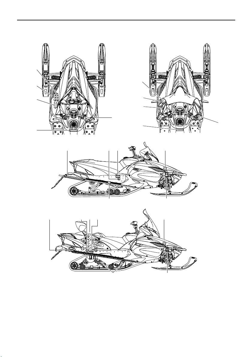
Page 9
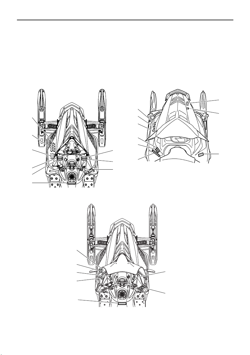
Location of the important labels
1
3
9
2
5
8
4
5
8
4
3
2
1
9
7
6
8
5
4
3
2
1
9
19
20
RS90P / RS90PLT
RST90PGT / RST90PTF
RST90
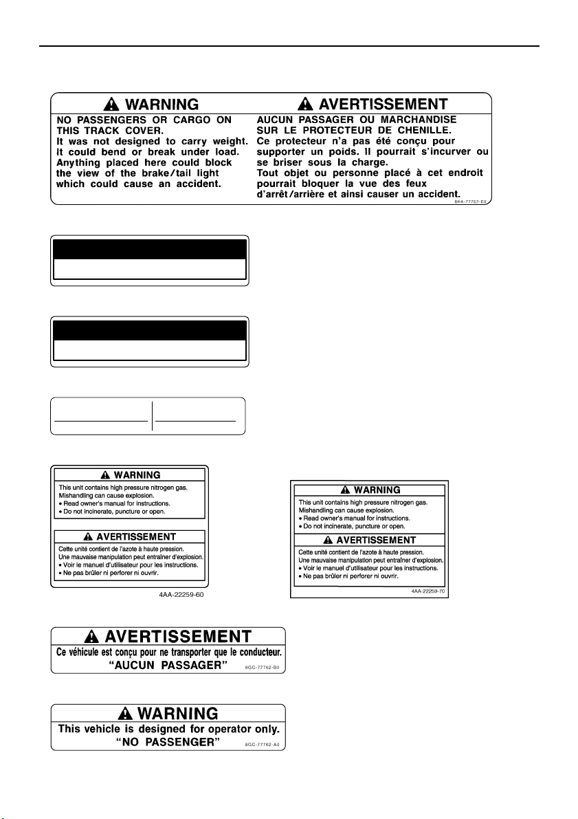
ESU12678
Read and understand all of the labels on your vehicle. They contain important information for
safe and proper operation of your vehicle. Never remove any labels from your vehicle. If a label
becomes difficult to read or comes off, a replacement label is available from your Yamaha dealer.
For CANADA
1
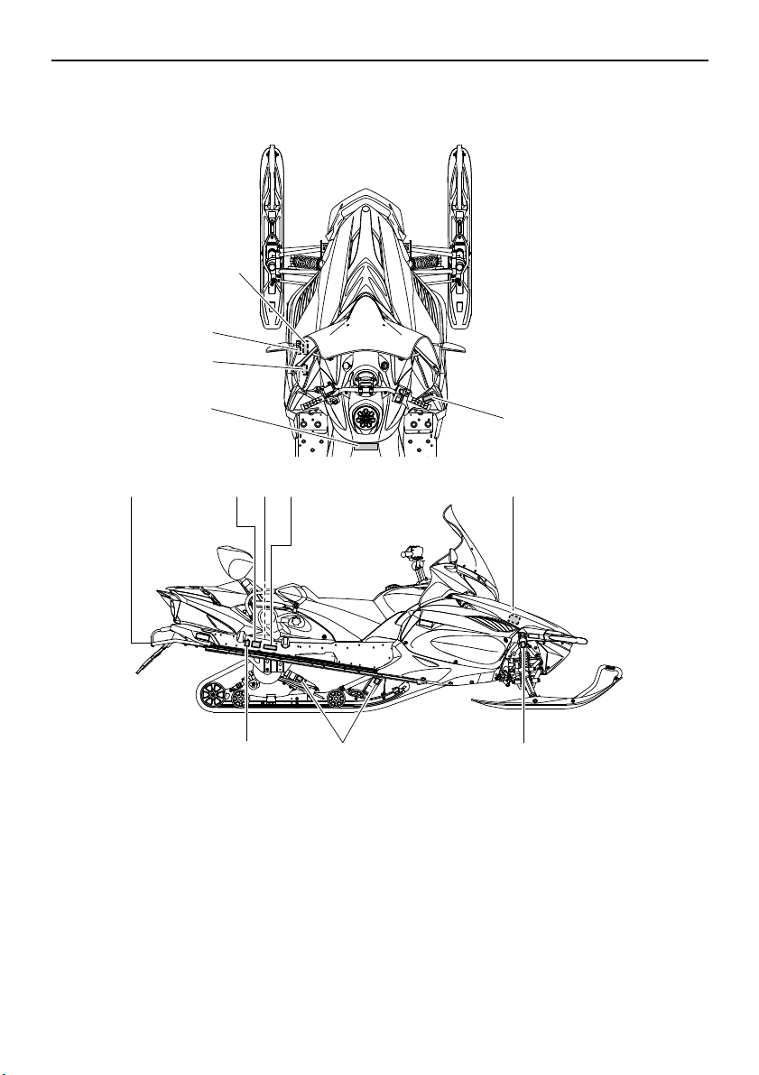
Page 10
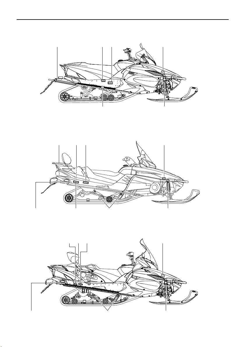
Location of the important labels
12
11
10
13
18
18
12
17
15
11
14
10
17
11
12
18
16
17,18
15
10
RS90P / RS90PLT
RST90PGT / RST90PTF
RST90
16
2
Page 11
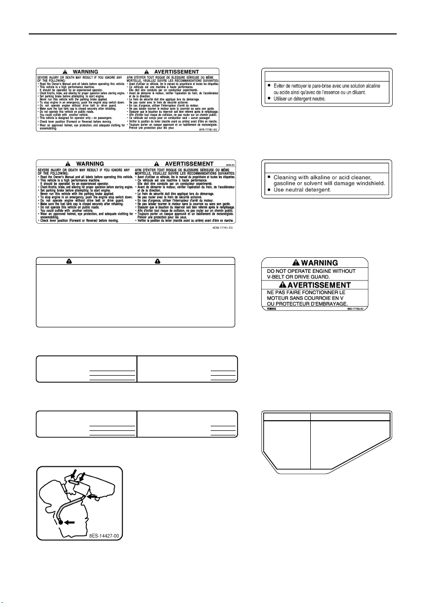
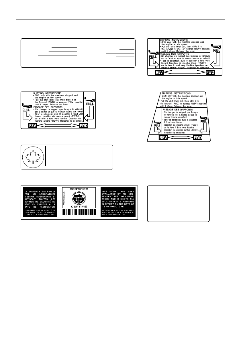
Location of the important labels
ATTENTION
8ET-2815K-10
TUNE-UP SPECIFICATIONS
ENGINE
1.SPARK PLUG
2.SPARK PLUG GAP
3.IDLE SPEED
SPECIFICATION S DE LA MISE AU P OINT
MOTEUR
1.TYPE DE BOUGIE
2.ECARTEMENT DES ÉLECTRODES
3.RÉGIME DE RALENTI
CR8E(NGK)
0.7 ~ 0.8 mm (0.028 ~ 0.031 in)
1300 ± 50 r/min
CR8E(NGK)
0.7 ~ 0.8 mm
1300 ± 50 r/min
8HF
8HF-1417E-00
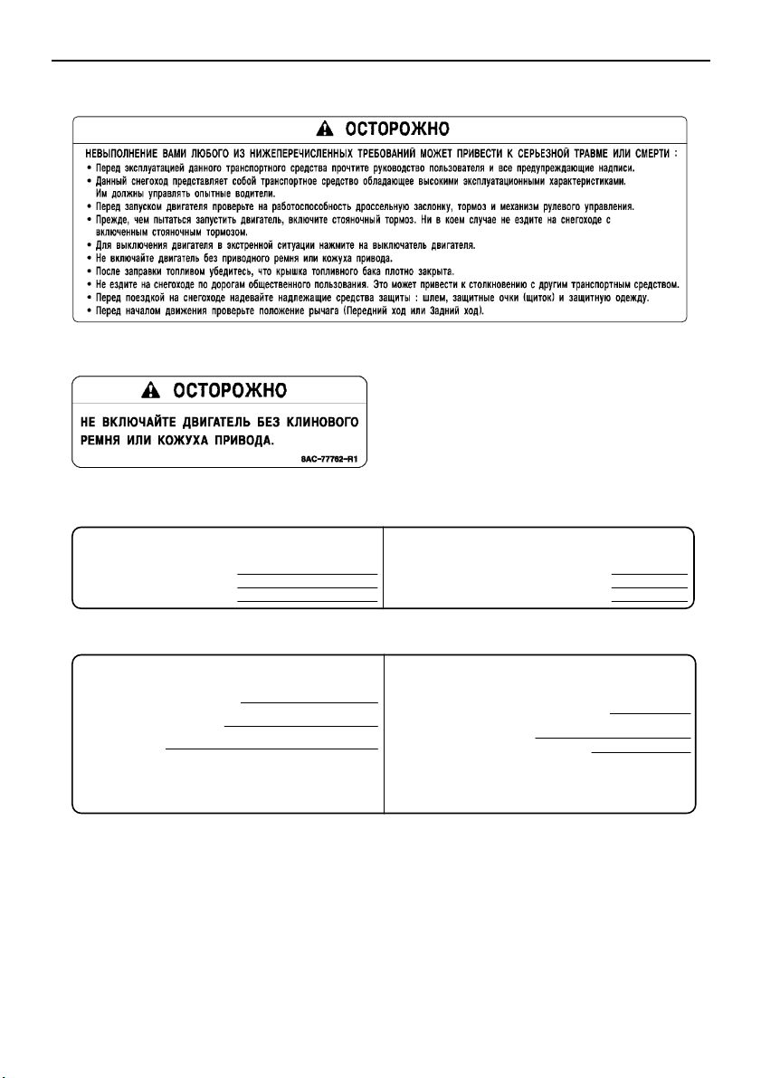
NOTICE
8ET-2815K-00
SEVERE INJURY OR DEATH MAY RESULT IF YOU IGNORE ANY OF
THE FOLLOWING:
•
Read the Owner’s Manual and all labels before operating this vehicle.
• This vehicle is a high performance machine.
It should be operated by an experienced operator.
•
Check throttle, brake, and steering for proper operation before starting engine.
• Set parking brake before attempting to start engine.
Never run this vehicle with the parking brake applied.
•
To stop engine in an emergency, push the engine stop switch down.
• Do not operate engine without drive belt or drive guard.
• Make sure the fuel tank cap is closed securely after refueling.
• Do not operate this vehicle on public roads.
You could collide with another vehicle.
• Check lever position (Forward or Reverse) before moving.
• Weal an approved helmet, eye protection, and adequate clothing
for snowmobiling.
AFIN D’ÉVITER TOUT RISQUE DE BLESSURE SÉRIEUSE OU MÊME MORTELLE,
VEUILLEZ SUIVRE LES RECOMMANDATIONS SUIVANTES:
•
Avant d’utiliser ce véhicule, lire le manuel du propriétaire et toutes les étiquettes.
• Ce véhicule est une machine à haute performance.
Elle doit être conduite par un conducteur expérimenté.
•
Avant de démarrer le moteur, vérifier l’opération du frein, de l’accélérateur
et de la direction.
• Le frein de sécurité doit être appliqué lors du démarrage.
Ne pas rouler avec le frein de sécurité actionné.
• En cas d’urgence, utiliser l’interrupteur d’arrêt du moteur.
• Ne pas laisser tourner le moteur sans la courroie ou sans son garde.
•
S’assurer que le bouchon du réservoir soit bien refermé après le remplissage.
•
Afin d’éviter tout risque de collision, ne pas rouler sur un chemin public.
•
Vérifier la position du levier (marche avant ou arrière) avant d’être en marche.
•
Toujours porter un casque approuvé et un habillement de motoneigiste.
Prévoir une protection pour les yeux.
WARNING AVERTISSEMENT
8HF-77761-E0
NOTICE ATTENTION
Severe engine damage
can result from oil loss if
crankcase breather hoses
are not installed correctly.
Inspect hoses and clamps
for correct installation
after battery service or
air box removal.
See Service Manual.
Des dommages graves risquent de survenir par
suite de fuites d’huile résultant d’un mauvais
branchement des tuyaux de reniflard du carter.
Après l’entretien de la batterie ou après la
dépose de I’épurateur d’air, assurezvous que les brides et les tuyaux
sont installès correctement.
Consultez le manuel
d’entretien.
8GS-2815J-E0
TUNE-UP SPECIFICATIONS
ENGINE
1.SPARK PLUG
2.SPARK PLUG GAP
3.IDLE SPEED
SPECIFICATION S DE LA MISE AU P OINT
MOTEUR
1.TYPE DE BOUGIE
2.ECARTEMENT DES ÉLECTRODES
3.RÉGIME DE RALENTI
CR8E(NGK)
0.7 ~ 0.8 mm (0.028 ~ 0.031 in)
1400 ± 100 r/min
CR8E(NGK)
0.7 ~ 0.8 mm
1400 ± 100 r/min
8ES
8ES-1417E-00
1 RS90P / RS90PLT 2
1 RST90 3
1 RST90PGT / RST90PTF 4
5 RS90P / RS90PLT / RST90PGT / RST90PTF
6 RST905 RST90
7 RST90
3
Page 12
Location of the important labels
DRIVE
1. CHAIN CASE OIL Q’TY
2. CHAIN CASE OIL TYPE
3. TRACK TENSION
* FOR MORE INFO: SEE SERVICE MANUAL FOR THIS
MODEL.
* SPECIFICATIONS SUBJECT TO CHANGE WITHOUT
NOTICE.
ENTRAÎNEMENT
1. CAPACITÉ D’HUILE DU CARTER DE CHAÎNE
2. TYPE D’HUILE DU CARTER DE CHAÎNE
3. FLÈCHE DE LA CHENILLE
* POUR PLUS DE DÉTAIL: VOIR LE MANUEL D’ATELIER
POUR CE MODÈLE.
* LES CARACTÉRISTIQUE TECHNIQUES SONT
SUSCEPTIBLES DE CHANGER SANS NOTIFICATION
PRÉALABLE.
250 cm³ (8.5 oz)
GL-3 75W or 80W
30 ~ 35 mm (1.18 ~ 1.38 in)/100 N (10 kg, 22 lb)
250 cm³
GL-3 75W or 80W
8ES-47578-00
30 ~ 35 mm/100 N (10 kg)
TUNE-UP SPECIFICATIONS
SPECIFICATION S DE LA MISE AU POINT
8ER-E0
8ER-77763-E0
8FR-77763-E0
•
C
M
V
S
S
•
C
A
N
A
D
A
•
N
S
V
A
C
•
T
R
A
N
S
P
O
R
T
506
This spark ignition system meets all requirements of the
Canadian Interference Causing Equipment Regulations.
Ce système d’allumage par étincelle de véhicule
respecte toutes les exigences du Règlement sur le
matériel brouilleur du Canada.
3JK-82377-10
88C-77769-00
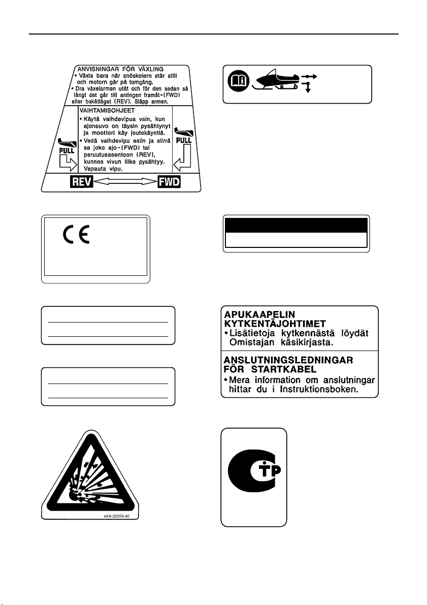
8HF-77763-E0
JUMPER CABLE CONNECTION LEADS
• For connecting procedures, refer to
Owner’s Manual.
FILS DE BRANCHEMENT DES CÂBLES
DE DÉMARRAGE
•
Effectuer le branchement des câbles
de démarrage conformément aux
instructions du Manuel du propriétaire.
8FA-E0
8FA-2389C-E0
8 9 RS90P / RS90PLT
9 RST90 9 RST90PGT / RST90PTF
10
1211
4
Page 13
Location of the important labels
20kg {44lbs}
LOAD LIMIT / CHARGE LIMITE
8FM-24897-01
10kg {22lbs}
LOAD LIMIT / CHARGE LIMITE
8ET-24897-00
MAX. TOWING FORCE
FORCE DE REMORQUAGE MAX.
1176 N (120 kgf), 264 lbf
MAX. VERTICAL FORCE
FORCE VERTICALE MAX.
147 N (15 kgf), 33 lbf
8GS-2817S-E0
13 RS90PLT
14 RST90
15 RST90 / RST90PGT / RST90PTF
16 RST90 / RST90PGT / RST90PTF
17 RST90 / RST90PTF 18 RS90P / RS90PLT /
RST90PGT / RST90PTF
19 RS90P / RS90PLT
20 RS90P / RS90PLT
5
Page 14
Location of the important labels
4
3
2
1
5
RS90PLT
11
8
10
9
RS90PLT
12
12
8
11
7
10
6
12
12
RST90PGT / RST90PTF
RST90PGT / RST90PTF
1
2
5
3
4
For EUROPE
6
Page 15
Location of the important labels
TUNE-UP SPECIFICATIONS
ENGINE
1.SPARK PLUG
2.SPARK PLUG GAP
3.IDLE SPEED
SPECIFICATIONS DE LA MISE AU POINT
MOTEUR
1.TYPE DE BOUGIE
2.ECARTEMENT DES ÉLECTRODES
3.RÉGIME DE RALENTI
CR8E(NGK)
0.7 ~ 0.8 mm (0.028 ~ 0.031 in)
1300 ± 50 r/min
CR8E(NGK)
0.7 ~ 0.8 mm
1300 ± 50 r/min
8HF
8HF-1417E-00
DRIVE
1. CHAIN CASE OIL Q’TY
2. CHAIN CASE OIL TYPE
3. TRACK TENSION
* FOR MORE INFO: SEE SERVICE MANUAL FOR THIS
MODEL.
* SPECIFICATIONS SUBJECT TO CHANGE WITHOUT
NOTICE.
ENTRAÎNEMENT
1. CAPACITÉ D’HUILE DU CARTER DE CHAÎNE
2. TYPE D’HUILE DU CARTER DE CHAÎNE
3. FLÈCHE DE LA CHENILLE
* POUR PLUS DE DÉTAIL: VOIR LE MANUEL D’ATELIER
POUR CE MODÈLE.
* LES CARACTÉRISTIQUE TECHNIQUES SONT
SUSCEPTIBLES DE CHANGER SANS NOTIFICATION
PRÉALABLE.
250 cm³ (8.5 oz)
GL-3 75W or 80W
30 ~ 35 mm (1.18 ~ 1.38 in)/100 N (10 kg, 22 lb)
250 cm³
GL-3 75W or 80W
8ES-47578-00
30 ~ 35 mm/100 N (10 kg)
TUNE-UP SPECIFICATIONS
SPECIFICATIONS DE LA MISE AU POINT
8ER-E0
8ER-77763-E0
8HF-77763-E0
1
2
3
4
5 RS90PLT 5 RST90PGT / RST90PTF
7
Page 16
Location of the important labels
20kg {44lbs}
MAX.BELASTNING/RASKAIN TAAKKA
8FM-24897-11
8FA-S0
8FA-2389C-S0
<
1176 N
<
147 N
8HF-2817S-00
8HW-2156A-00
RS10ST
88.4 kW 313 kg
8HX-2156A-00
RS10VTGT
88.4 kW 347 kg
8HY-2156A-00
RS10SUV
88.4 kW 349 kg
8AC-2817L-00
YAMAHA MOTOR CO., LTD.
2500 SHINGAI, IWATA, JAPAN
2012
6 RST90PGT / RST90PTF
10
8 RS90PLT
8 RST90PGT
8 RST90PTF
11
12
7 RST90PGT / RST90PTF
9 RS90PLT
8
Page 17
Location of the important labels
******
*** kW *** kg
1
23
YAMAHA MOTOR CO., LTD.
2500 SHINGAI, IWATA, JAPAN
****
1
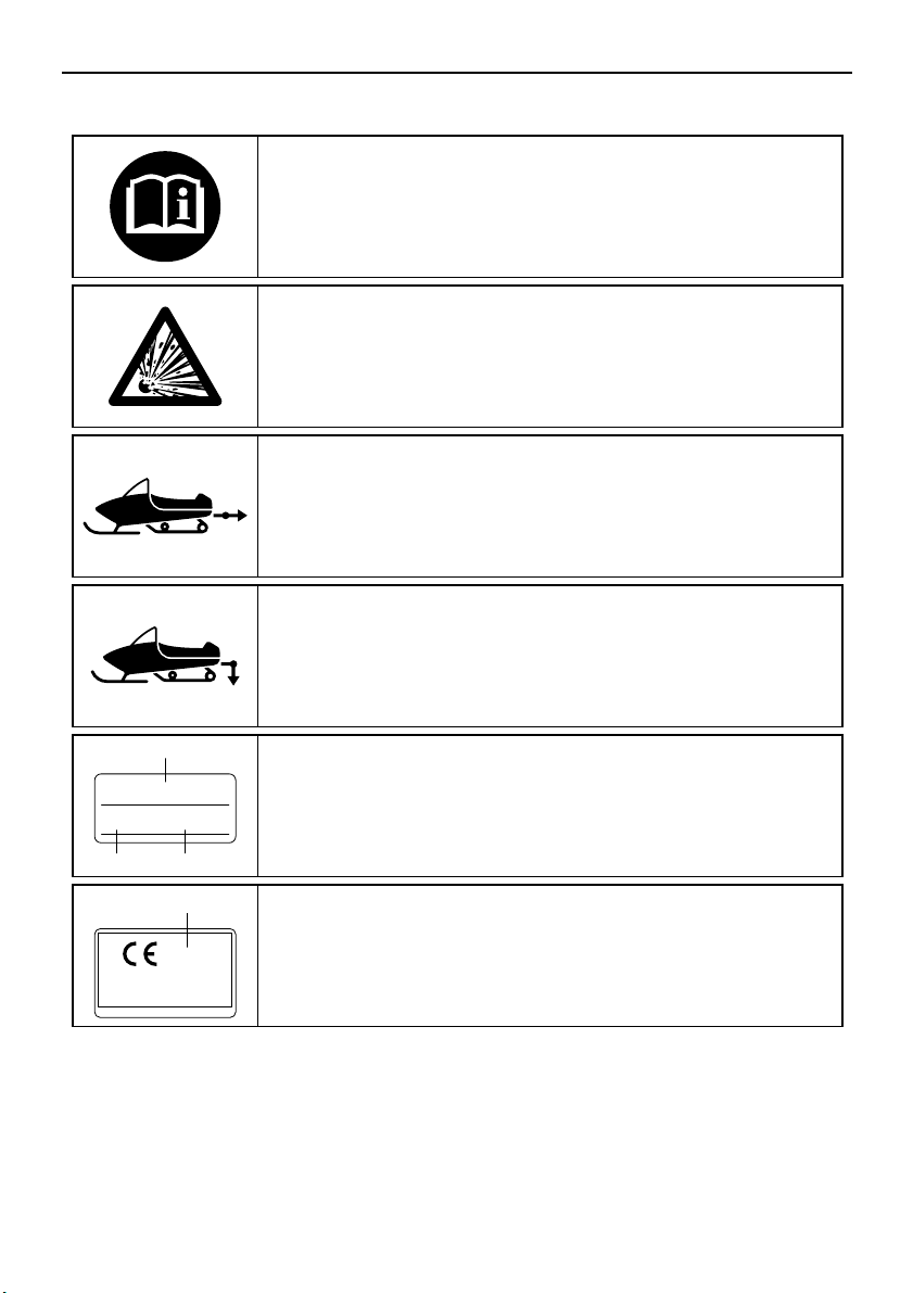
Read the Owner’s manual.
This unit contains high-pressure nitrogen gas.
Mishandling can cause an explosion. Do not incinerate,
puncture or open.
This pictogram shows the sled hitch tow weight limit
(combined weight of the sled and all cargo in the sled).
Overloading can cause loss of control.
Loss of control can result in severe injury or death.
This pictogram shows the sled hitch tongue weight limit
(weight on the sled tongue).
Overloading can cause loss of control.
Loss of control can result in severe injury or death.
1
2
3
Model Name
Max. Power
Mass In Running Order
1
Year of construction
Familiarize yourself with the following pictograms and read the explanatory text.
9
Page 18
Location of the important labels
RST90PGT / RST90PTF
1
2
5
3
4
9
10
8
7
6
11
11
12
For RUSSIA
10
Page 19
Location of the important labels
TUNE-UP SPECIFICATIONS
ENGINE
1.SPARK PLUG
2.SPARK PLUG GAP
3.IDLE SPEED
SPECIFICATIONS DE LA MISE AU POINT
MOTEUR
1.TYPE DE BOUGIE
2.ECARTEMENT DES ÉLECTRODES
3.RÉGIME DE RALENTI
CR8E(NGK)
0.7 ~ 0.8 mm (0.028 ~ 0.031 in)
1300 ± 50 r/min
CR8E(NGK)
0.7 ~ 0.8 mm
1300 ± 50 r/min
8HF
8HF-1417E-00
DRIVE
1. CHAIN CASE OIL Q’TY
2. CHAIN CASE OIL TYPE
3. TRACK TENSION
* FOR MORE INFO: SEE SERVICE MANUAL FOR THIS
MODEL.
* SPECIFICATIONS SUBJECT TO CHANGE WITHOUT
NOTICE.
ENTRAÎNEMENT
1. CAPACITÉ D’HUILE DU CARTER DE CHAÎNE
2. TYPE D’HUILE DU CARTER DE CHAÎNE
3. FLÈCHE DE LA CHENILLE
* POUR PLUS DE DÉTAIL: VOIR LE MANUEL D’ATELIER
POUR CE MODÈLE.
* LES CARACTÉRISTIQUE TECHNIQUES SONT
SUSCEPTIBLES DE CHANGER SANS NOTIFICATION
PRÉALABLE.
250 cm³ (8.5 oz)
GL-3 75W or 80W
30 ~ 35 mm (1.18 ~ 1.38 in)/100 N (10 kg, 22 lb)
250 cm³
GL-3 75W or 80W
8ES-47578-00
30 ~ 35 mm/100 N (10 kg)
TUNE-UP SPECIFICATIONS
SPECIFICATIONS DE LA MISE AU POINT
8HP-77761-R0
1
2
3
4
11
Page 20
Location of the important labels
8HF-77763-S0
20kg {44lbs}
MAX.BELASTNING/RASKAIN TAAKKA
8FM-24897-11
8FA-S0
8FA-2389C-S0
<
1176 N
<
147 N
8HF-2817S-00
8HX-2156A-00
RS10VTGT
88.4 kW 347 kg
8HY-2156A-00
RS10SUV
88.4 kW 349 kg
8AC-2817L-00
YAMAHA MOTOR CO., LTD.
2500 SHINGAI, IWATA, JAPAN
2012
8JF-2818P-R0
56
7
9 RST90PGT
9 RST90PTF
10
1211
8
12
Page 21
Safety information
ESU10193
As the vehicle’s owner, you are responsible
for the safe and proper operation of your
snowmobile. When you ride your snowmobile, you must know and use the following for
your safety. Severe injury or death may result
if you ignore any of the following.
Before you operate your snowmobile
● Read the Owner’s Manual and all labels.
Become familiar with all of the operating
controls and their function. Consult a
Yamaha dealer about any control or function you do not understand.
● Wear protective clothing. Wear an ap-
proved helmet, and a face shield or goggles. Also, wear a good quality snowmobile
suit, boots, and a pair of gloves or mittens
that will permit use of your thumbs and fingers for operation of the controls.
creases the possibility of an accident or
equipment damage. See page 55 for a list
of pre-operation checks.
● Apply the parking brake before starting the
engine. Never drive the snowmobile with
the parking brake applied. This may overheat the brake disc and reduce braking ability.
While using your snowmobile
● This snowmobile was not manufactured for
use on public streets, roads, or highways.
Such use is prohibited by law, and you
could collide with another vehicle.
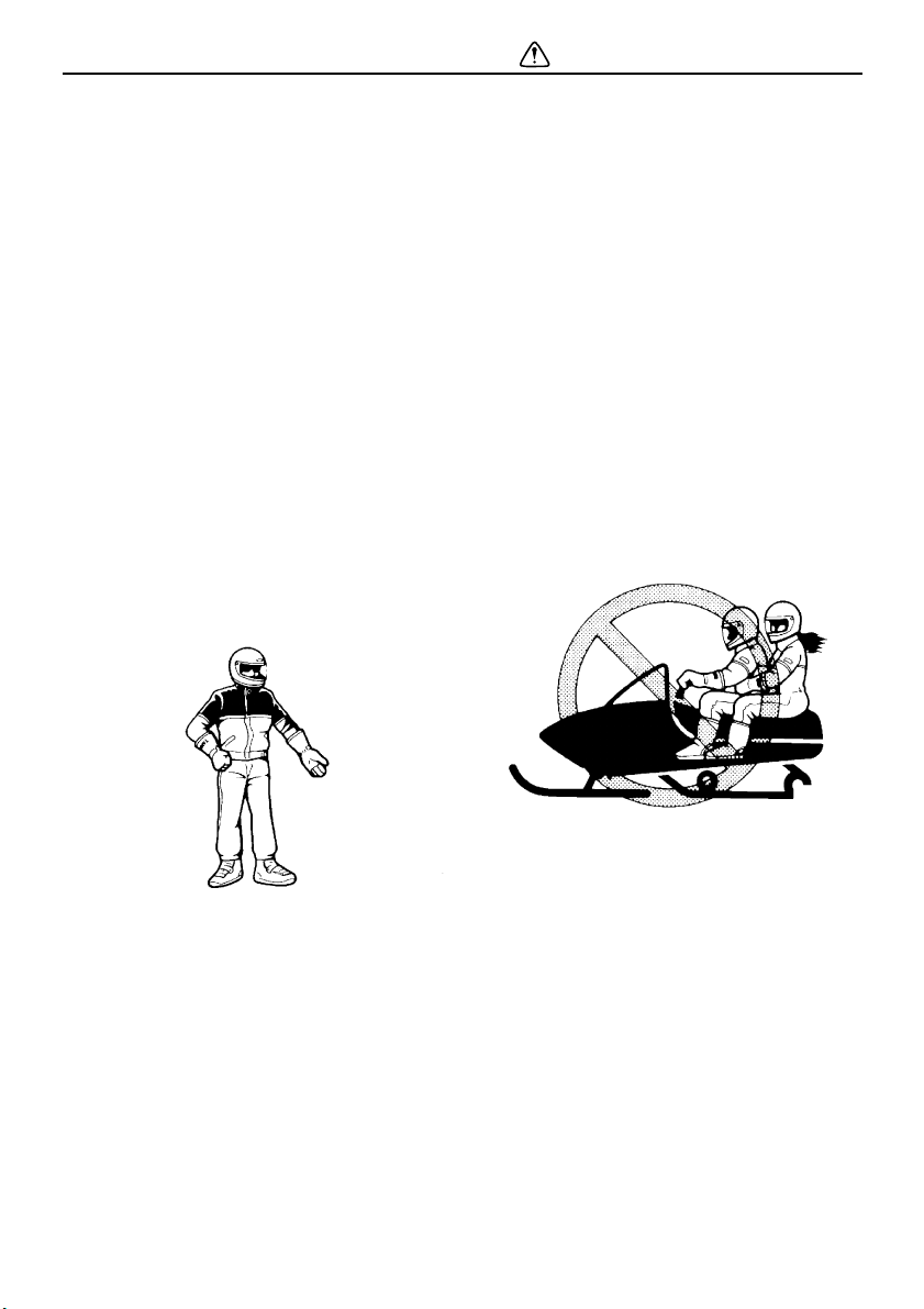
● RS90P and RS90PLT are designed to carry
the OPERATOR ONLY. Passengers are
prohibited. Carrying a passenger can cause
loss of control.
● Do not operate the snowmobile after or
while drinking alcohol or taking drugs. Your
ability to operate the snowmobile is reduced by the influence of alcohol or drugs.
Prepare your snowmobile
● Perform the pre-operation checks each
time you use the vehicle to make sure it is
in safe operating condition. Failure to inspect or maintain the vehicle properly in-
● Be careful where you ride. There may be
obstacles hidden beneath the snow. Stay
on established trails to minimize your exposure to hazards. Ride slowly and cautiously
when you ride off of established trails. Hitting a rock or stump, or running into wires
could cause an accident and injury.
● This snowmobile is not designed for use on
surfaces other than snow or ice. Use on dirt,
sand, grass, rocks, or bare pavement may
cause loss of control and may damage the
snowmobile.
13
Page 22

Safety information
● Always ride with other snowmobilers when
going on a ride. You may need help if you
run out of fuel, have an accident, or damage
your snowmobile.
● Many surfaces such as ice and hardpacked
snow require much longer stopping distances. Be alert, plan ahead and begin decelerating early. The best braking method on
most surfaces is to release the throttle and
apply the brake gently—not suddenly.
Avoid carbon monoxide poisoning
All engine exhaust contains carbon monoxide, a deadly gas. Breathing carbon monoxide
can cause headaches, dizziness, drowsiness,
nausea, confusion, and eventually death.
Carbon monoxide is a colorless, odorless,
tasteless gas which may be present even if
you do not see or smell any engine exhaust.
Deadly levels of carbon monoxide can collect
rapidly and you can quickly be overcome and
be unable to save yourself. Also, deadly levels of carbon monoxide can linger for hours or
days in enclosed or poorly-ventilated areas. If
you experience any symptoms of carbon
monoxide poisoning, leave the area immediately, get fresh air, and SEEK MEDICAL
TREATMENT.
● Do not run the engine indoors. Even if you
try to ventilate engine exhaust with fans or
open windows and doors, carbon monoxide
can rapidly reach dangerous levels.
● Do not run the engine in poorly ventilated or
partially enclosed areas such as barns, garages, or carports.
● Do not run the engine outdoors where en-
gine exhaust can be drawn into a building
through openings such as windows and
doors.
Genuine Yamaha Accessories
Choosing accessories for your snowmobile is
an important decision. Genuine Yamaha Accessories, which are available only from a
Yamaha dealer, have been designed, tested,
and approved by Yamaha for use on your
snowmobile. Many companies with no connection to Yamaha manufacture parts and accessories or offer other modifications for
Yamaha vehicles. Yamaha is not in a position
to test the products that these aftermarket
companies produce. Therefore, Yamaha can
neither endorse nor recommend the use of
accessories not sold by Yamaha or modifications not specifically recommended by
Yamaha, even if sold and installed by a
Yamaha dealer.
Maintenance and storage
● When laying the snowmobile on its side for
maintenance, use a suitable stand to keep
it in a stable and level position.
● Do not leave the snowmobile on its left side
for an extended period of time. Fuel may
leak out from the fuel breather hose.
● Do not allow anyone to stand behind the
snowmobile when starting, inspecting, or
adjusting the snowmobile. A broken track,
track fittings, or debris thrown by the track
could be dangerous to the operator or bystanders.
● Modifications made to the snowmobile not
approved by Yamaha, or the removal of
original equipment may render your snowmobile unsafe for use, which may cause severe personal injury. Modifications may
also make the snowmobile illegal to use.
● Never store the snowmobile with fuel in the
fuel tank inside a building where ignition
sources are present such as hot water and
space heaters, an open flame, sparks,
14
Page 23

clothes dryers, and the like. Allow the engine to cool off before storing the snowmobile in an enclosed space.
Safety information
15
Page 24
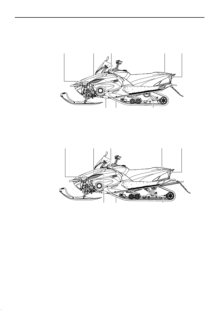
Description
1,2,3 4 5,6,7 8,9 10
111213
1,2,3
RS90P
RS90PLT
4 5,6,7 8,9 10
111213
ESU10261
1. Battery
2. Main fuse
3. Air filter
4. Oil filler cap
5. Fuse box
6. Coolant reservoir
7. Coolant recovery tank
8. Storage compartment
9. Tool kit
10. Tail/brake light
11. Slide rail suspension
12. Drive track
13. V-belt holder
16
Page 25
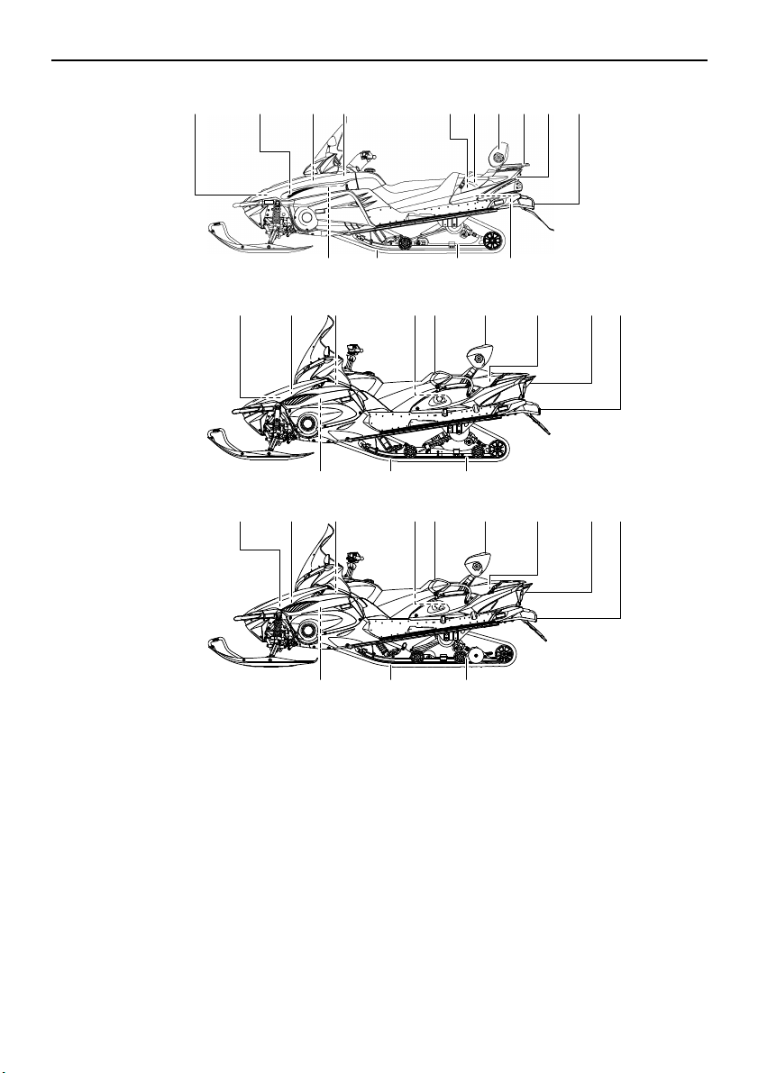
1,2,3 4 7 8 9 10,11,12 13
151617
1,2,3 4 9 10,11,12 13 14
151617
5,6
5,6
14
RST90PGT
RST90
RST90PTF
78
10,12 1,2,3,4 5,620 7 8 9 1913 14
15 181617
Description
1. Battery
2. Main fuse
3. Air filter
4. Oil filler cap
5. Fuse box
6. Coolant reservoir
7. Passenger grip warmer switch
8. Passenger grip
9. Backrest
10. Storage compartment
11. Storage pouch (RST90PGT / RST90PTF)
12. Tool kit
13. Tail/brake light
14. Tow hitch [RST90PGT (RUSSIA) /
RST90PTF (CANADA)(RUSSIA)] / tow hitch
bracket [RST90 / RST90PGT
(CANADA)(EUROPE) / RST90PTF (EUROPE)]
15. Slide rail suspension
16. Drive track
17. V-belt holder
18. Solo touring storage area (RST90)
19. Rear carrier (RST90)
20. Throttle stop screw (RST90)
17
Page 26
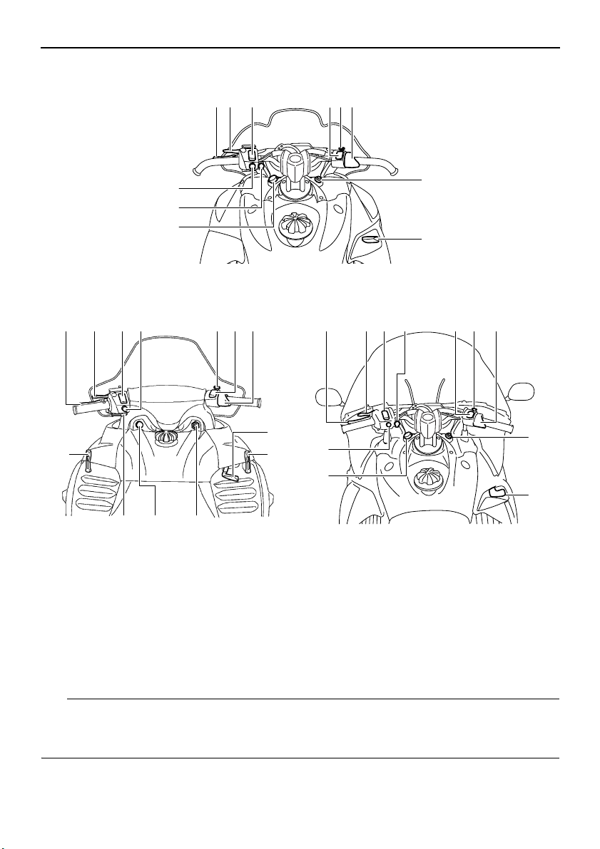
Description
TIP
1 235 647
8
9
10
11
12311
13 810
4 76
9
12
12
1
RS90P / RS90PLT
RST90PGT / RST90PLTRST90
23 647
5
10
8
9
11
1. Brake lever
2. Parking brake lever
3. Grip warmer adjusting switch
4. Thumb warmer adjusting switch
5. Helmet shield heater jack [RS90P /
RS90PLT (CANADA) / RST90PGT
(CANADA) / RST90PTF (CANADA)]
6. Engine stop switch
● The snowmobile you have purchased may differ slightly from those shown in the figures of
this manual.
● Design and specifications are subjected to change without notice.
7. Throttle lever
8. Main switch
9. Shift lever
10. Auxiliary DC jack
11. Headlight beam switch
12. Shroud latch (RST90)
13. Starter (choke) lever (RST90)
18
Page 27
ESU13740
TIP
TIP
13
2
Main switch
The main switch controls the ignition and
lighting systems. The various positions are
described below.
1. Off
2. On
3. Start
Off
The ignition circuit is switched off.
The key can be removed only in this position.
On
The ignition circuit is switched on.
Start
The starting circuit is switched on.
The starter motor cranks the engine.
NOTICE: Release the switch immediately
after the engine starts.
● RS90P / RS90PLT / RST90PGT /
RST90PTF: The headlights and taillight
come on after the engine is started.
● RST90: The headlights, meter lighting, and
taillights come on after the engine is started.
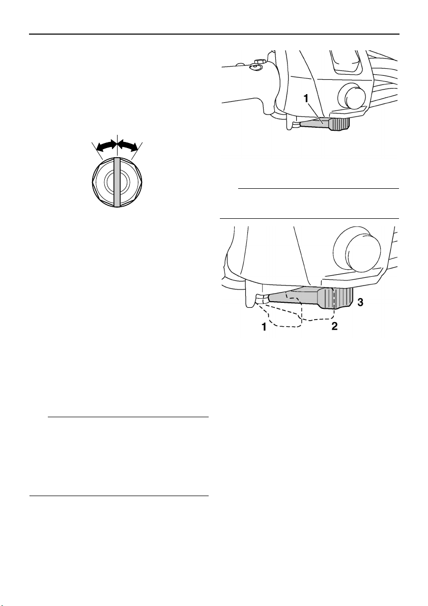
ESU10301
Starter (choke) lever (RST90)
Use the starter (choke) lever when starting
and warming up a cold engine.
[ECS00021]
Control functions
1. Starter (choke) lever
Refer to the “Starting the engine” section on
page 57 for proper operation.
1. When starting a cold engine.
2. Warming up
3. When the engine is warm.
ESU10312
Throttle lever
Once the engine is running cleanly, squeezing the throttle lever will increase the engine
speed and cause engagement of the drive
train. Regulate the speed of the snowmobile
by varying the throttle position. Because the
throttle is spring-loaded, the snowmobile will
decelerate, and the engine will return to idle
when it is released.
19
Page 28
Control functions
WARNING
TIP
1. Throttle lever
ESU13750
Throttle override system (T.O.R.S.)
EWS00041
If the T.O.R.S. is activated, make sure that
the cause of the malfunction has been corrected and that the engine can be operated
without a problem before restarting the
engine. Continuing to operate with a malfunction could cause loss of control or
damage.
If the throttle valves or throttle cable malfunctions during operation, the T.O.R.S. will be activated when the throttle lever is released.
The T.O.R.S. is designed to override the fuel
injection (RS90P / RS90PLT / RST90PGT /
RST90PTF) or ignition (RST90) and limit the
engine speed to less than the clutch engagement speed if the throttle valves fail to return
to the idle position when the throttle lever is
released. (See page 133 for the clutch engagement speed.)
Malfunc-
tion
T. O. R .S .
will be ac-
tivated.
Throttle
lever
Throttle
valve
T.O. R.S.
Idling Riding
Released Squeezed Released
Closed Open Open
Engine
runs
properly.
Engine
runs
properly.
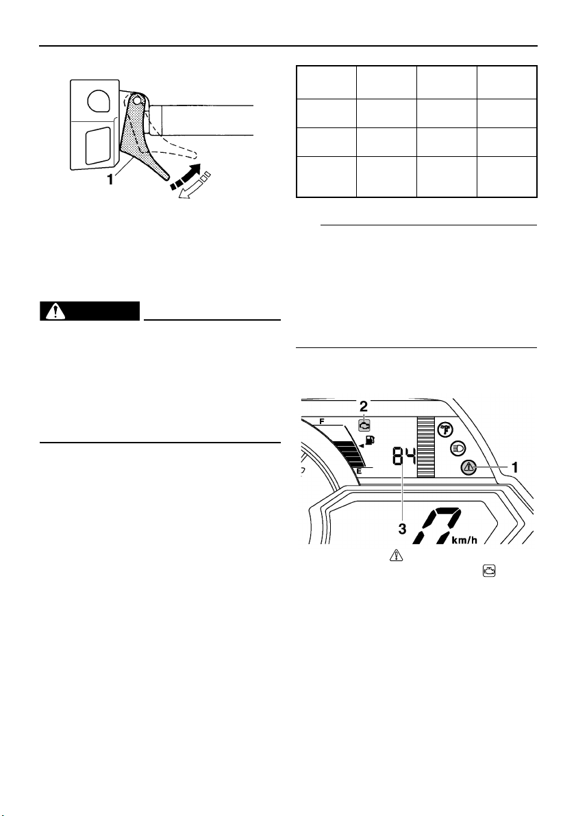
If the T.O.R.S. is activated, the warning light
and engine trouble warning indicator flash,
and the two-digit code “84” displays (RS90P /
RS90PLT / RST90PGT / RST90PTF) or
flashes (RST90) in the meter display. If this
occurs, have a Yamaha dealer check the system as soon as possible.
RS90P / RS90PLT / RST90PGT /
RST90PTF
1. Warning light “ ”
2. Engine trouble warning indicator “ ”
3. Two-digit code “84”
20
Page 29
Control functions
TIP
FHI
E LO EPS
10
9
6
8
12 3 4 5
7
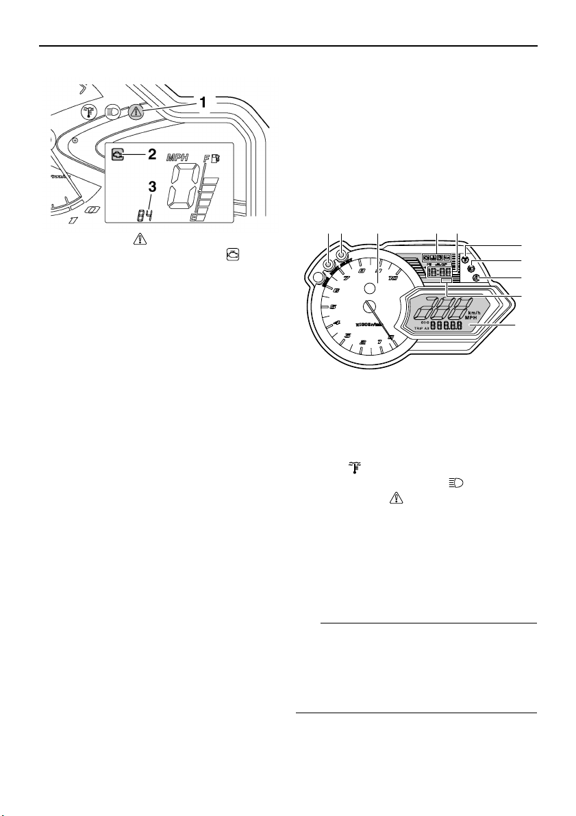
RST90
1. Warning light “ ”
2. Engine trouble warning indicator “ ”
3. Two-digit code “84”
ESU14101
Multi-function meter unit
RS90P / RS90PLT / RST90PGT /
RST90PTF
The multi-function meter unit is equipped with
the following:
● a digital speedometer
● a tachometer
● an odometer
● two tripmeters (which show the distance
traveled since they were last set to zero)
● a fuel reserve tripmeter (which shows the
distance traveled since the fuel level warning indicator and warning light came on)
● an oil change tripmeter (which shows the
distance traveled since the periodic oil
change interval was reached)
● a clock
● warning indicators (which show engine
trouble, coolant temperature, fuel level, and
oil level warnings)
● indicator lights (which show high beam and
low coolant temperature conditions)
● a warning light (which shows warnings to-
gether with the warning indicators)
● a fuel meter (which shows the fuel remain-
ing in the fuel tank)
● a grip/thumb warmer level indicator (which
shows the grip warmer level or the thumb
warmer level)
● a display brightness control function
When the key is turned to the on position, the
tachometer needle makes one sweep, and
the low coolant temperature indicator light,
the warning light, and all segments of the
meter unit display come on and go off.
1. “RESET” button
2. “SELECT” button
3. Tachometer
4. Warning indicators
5. Clock
6. Low coolant temperature indicator
light “ ”
7. High beam indicator light “ ”
8. Warning light “ ”
9. Electric power steering warning indicator
“EPS”
10. Meter display
The grip warmer level is initially displayed for
5 seconds, then the display switches to the
fuel meter.
To switch the speedometer, odometer, and
tripmeter displays between kilometers and
miles, select the odometer mode “ODO”, and
then push the “SELECT” button for at least 10
seconds while the snowmobile is stopped.
21
Page 30
Control functions
TIP
1
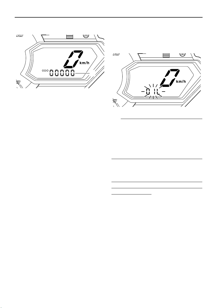
Odometer and tripmeter modes
E LO
1. Odometer/tripmeter/fuel reserve tripmeter
Pushing the “SELECT” button switches the
display between the odometer mode “ODO”
and the tripmeter modes “TRIP A” and “TRIP
B” in the following order:
ODO → TRIP A → TRIP B → ODO
If the fuel level warning indicator and warning
light come on (see page 26), the odometer
display will automatically change to the fuel
reserve tripmeter mode “TRIP F” and start
counting the distance traveled from that point.
In that case, push the “SELECT” button to
switch the display between the various tripmeter and odometer modes in the following
order:
TRIP F → ODO → TRIP A → TRIP B → TRIP
F
To reset a tripmeter, select it by pushing the
“SELECT” button, and then push the “RESET” button for at least 1 second. If you do not
reset the fuel reserve tripmeter manually, it
will reset itself automatically, and the display
will return to the prior mode after the snowmobile has been refueled and traveled 5 km (3
mi).
Oil change tripmeter
When the periodic oil change interval is
reached at the initial 800 km (500 mi), then at
every 4000 km (2500 mi) thereafter, the oil
change tripmeter and “OIL” flash alternately in
the odometer display, and the tripmeter starts
22
counting the distance traveled from that point.
When this occurs, change the engine oil as
soon as possible. (See page 87 for the oil
change procedure.)
E LO
● The oil change tripmeter will flash only
when the snowmobile is stopped.
● To return to the previous display mode,
push the “SELECT” button. To display the
oil change tripmeter again, turn the key to
the off position, then back to the on position.
After changing the engine oil, reset the oil
change tripmeter as follows.
To reset the oil change tripmeter (when the
engine oil was changed after the oil change
tripmeter appeared)
1. To display the oil change tripmeter, turn
the key to the on position.
2. Push the “RESET” button for at least 1
second while the oil change tripmeter and
“OIL” are flashing alternately in the odometer display. The distance traveled since
the last oil change and “OIL” will flash alternately in the odometer display.
3. Push the “RESET” button for approximately 3 seconds. “00000” and “OIL” will
flash alternately in the odometer display 3
times, and then the display will return to
the previous display mode.
Page 31

Control functions
TIP
1
1
If the engine oil is changed before the oil
change tripmeter appears in the display (i.e.,
before the periodic oil change interval has
been reached), the tripmeter must be reset after the oil change for the next periodic oil
change to be indicated at the correct time.
In that case, reset the oil change tripmeter as
follows.
To reset the oil change tripmeter (when the
engine oil was changed before the oil change
tripmeter appeared)
1. Push the “SELECT” button until “ODO” is
displayed, and then push the “RESET”
button for at least 1 second. The distance
traveled since the last oil change and
“OIL” will flash alternately in the odometer
display.
2. Push the “RESET” button for approximately 3 seconds. “00000” and “OIL” will
flash alternately in the odometer display 3
times, and then the display will return to
the previous display mode.
Clock
3. Push the “RESET” button to change the
hour setting, and then push the “SELECT” button. The minute digits will start
flashing.
4. Push the “RESET” button to change the
minute setting, and then push the “SELECT” button. The clock starts when the
“SELECT” button is released.
The clock must be set again when the battery
is disconnected.
Display brightness control
This function allows you to adjust the brightness of the meter unit display to suit the outdoor lighting conditions.
F
E
1. Clock
To set the clock
1. Turn the key to the on position.
2. Push the “SELECT” button and “RESET”
button simultaneously until the hour digits
start flashing.
1. Display brightness level
To adjust the display brightness
1. Turn the key to the off position.
2. Push and hold down the “SELECT” button.
3. Turn the key to the on position, and then,
after 5 seconds, release the “SELECT”
button.
4. Push the “RESET” button to select the
desired display brightness level, and then
push the “SELECT” button. The display
returns to the previous display mode.
RST90
The multi-function meter unit is equipped with
the following:
23
Page 32

Control functions
TIP
1 2 3 4 65 7
1
● a digital speedometer
● a tachometer
● an odometer
● a tripmeter (which shows the distance trav-
eled since it was last set to zero)
● warning indicators (which show engine
trouble, coolant temperature, fuel level, and
oil level warnings)
● indicator lights (which show high beam and
low coolant temperature conditions)
● a warning light (which shows warnings to-
gether with the warning indicators)
● a fuel meter (which shows the fuel remain-
ing in the fuel tank)
● a grip/thumb warmer level indicator (which
shows the grip warmer level or the thumb
warmer level)
After the engine is started, the tachometer
needle makes one sweep, and the low coolant temperature indicator light, the warning
light, and all segments of the meter unit display come on and go off.
To switch the speedometer, odometer, and
tripmeter displays between kilometers and
miles, select the odometer mode “ODO”, and
then push the select/reset button for at least
10 seconds while the snowmobile is stopped.
Odometer and tripmeter modes
Pushing the select/reset button switches the
display between the odometer mode “ODO”
and the tripmeter mode “TRIP” in the following
order:
ODO → TRIP → ODO
1. Tachometer
2. Low coolant temperature indicator
light “ ”
3. High beam indicator light “ ”
4. Warning light “ ”
5. Warning indicators
6. Meter display
7. Select/reset button
The grip warmer level is initially displayed for
5 seconds, then the display switches to the
fuel meter.
24
1. Odometer/tripmeter
To reset the tripmeter, push the select/reset
button for at least 1 second while the tripmeter
is displayed.
ESU10411
High beam indicator light “ ”
The high beam indicator light comes on when
the high beams of the headlights are switched
on. (See page 32 for headlight beam switch
operation.)
Page 33

Control functions
TIP
RS90P / RS90PLT / RST90PGT /
RST90PTF
1. High beam indicator light “ ”
RST90
1. High beam indicator light “ ”
ESU13761
Low coolant temperature indicator light “ ”
The low coolant temperature indicator light
comes on when the coolant temperature is
low and informs the rider that the snowmobile
should be warmed up. After the engine is
started, warm it up until the indicator light
goes off.
The snowmobile can be operated normally after the indicator light goes off.
RS90P / RS90PLT / RST90PGT /
RST90PTF
1. Low coolant temperature indicator
light “ ”
RST90
1. Low coolant temperature indicator
light “ ”
2. Warning light “ ”
3. Engine trouble warning indicator “ ”
4. Two-digit code “86”
● RS90P / RS90PLT / RST90PGT /
RST90PTF: Drive the snowmobile at low
speeds when the low coolant temperature
indicator light is on. If the engine speed is
too high, maximum engine speed is reduced to protect the engine.
● RST90: Drive the snowmobile at low
speeds when the low coolant temperature
indicator light is on. If the engine speed is
too high, the warning light and engine trouble warning indicator flash and the two-digit
25
Page 34

Control functions
TIP
code “86” flashes in the error code display.
When this occurs, maximum engine speed
is reduced to protect the engine.
ESU10427
Fuel meter and grip/thumb warmer level indicator
The fuel meter and grip/thumb warmer level
indicator have eight segments which show
the amount of fuel remaining in the fuel tank,
the grip warmer level, or the thumb warmer
level.
RS90P / RS90PLT / RST90PGT /
RST90PTF
1. Fuel meter and grip/thumb warmer level indicator
Fuel meter
The display segments of the fuel meter disappear towards “E” (Empty) as the fuel level decreases. When only one segment is left near
“E”, the fuel level warning indicator and the
warning light come on.
RS90P / RS90PLT / RST90PGT /
RST90PTF
1. Fuel level warning indicator “ ”
2. Warning light “ ”
RST90
RST90
1. Fuel meter and grip/thumb warmer level indicator
26
1. Fuel level warning indicator “ ”
2. Warning light “ ”
If the fuel level warning indicator and the
warning light come on, refuel as soon as possible.
The snowmobile must be stopped on a level
surface to obtain an accurate fuel meter reading, since the reading changes according to
the movement and inclination of the snowmobile.
Page 35

Control functions
TIP
1
1
Grip/thumb warmer level indicator
When the grip warmer adjusting switch is
pressed, the grip warmer indicator comes on
and the display switches to the grip warmer
level.
When the thumb warmer adjusting switch is
pressed, the thumb warmer indicator comes
on and the display switches to the thumb
warmer level.
See “Grip/thumb warmer adjusting switch” on
page 32 for detailed information.
RS90P / RS90PLT / RST90PGT /
RST90PTF
1. Grip warmer indicator “ ”
2. Thumb warmer indicator “ ”
RS90P / RS90PLT / RST90PGT /
RST90PTF
1. Grip warmer adjusting switch
RST90
1. Grip warmer adjusting switch
RST90
1. Grip warmer indicator “ ”
2. Thumb warmer indicator “ ”
1. Thumb warmer adjusting switch
● The grip/thumb warmer level is displayed
for 5 seconds after releasing the grip/thumb
warmer adjusting switch, then the display
switches to the fuel meter.
27
Page 36

Control functions
31 24
● The top segment of the grip/thumb warmer
level indicator flashes once when the
grip/thumb warmer adjustment reaches the
maximum level. The bottom segment of the
grip/thumb warmer level indicator flashes
once when the grip/thumb warmer adjustment reaches the minimum level.
● When the engine is started, the grip/thumb
warmer levels are set to the levels selected
when the engine was last stopped.
ESU13252
Fuel level warning
indicator “ ”
The fuel level warning indicator and the warning light come on when the fuel level is low.
(See page 26 for details.)
The fuel level warning indicator, the warning
light, the fuel meter indicator (RS90P /
RS90PLT / RST90PGT / RST90PTF), and all
segments of the fuel meter start to flash when
a malfunctioning sensor, disconnected coupler, broken lead, or short circuit is detected
by the self-diagnosis device of the snowmobile to warn the rider of any of the above problems.
If this occurs, have a Yamaha dealer inspect
the snowmobile as soon as possible.
RS90P / RS90PLT / RST90PGT /
RST90PTF
1. Fuel level warning indicator “ ”
2. Warning light “ ”
3. Fuel meter
4. Fuel meter indicator “ ”
RST90
1. Fuel level warning indicator “ ”
2. Warning light “ ”
3. Fuel meter
ESU10463
Oil level warning indicator “ ”
(RST90)
The oil level warning indicator and the warning light come on when the engine oil level is
low.
28
Page 37

Control functions
1. Oil level warning indicator “ ”
2. Warning light “ ”
If the oil level warning indicator and the warning light come on, place the snowmobile on a
level surface and allow it to idle for one
minute.
If the oil level warning indicator and the warning light go off, the engine oil level is sufficient,
however it is getting low. Add engine oil as
soon as possible.
If the oil level warning indicator and the warning light do not go off, check the engine oil level in the oil tank (see page 87 for engine oil
level checking procedures), and add engine
oil if necessary.
If the oil level warning indicator and the warning light still remain on, have a Yamaha dealer
check the snowmobile.
ESU13991
Oil level/pressure warning
indicator “ ” (RS90P /
RS90PLT / RST90PGT /
RST90PTF)
The oil level/pressure warning indicator has
two functions. The warning indicator comes
on when the engine oil level is low and when
the engine oil pressure is low. The functions
are explained in the following sections.
Oil level warning
The warning indicator and the warning light
come on when the engine oil level is low.
1. Oil level/pressure warning indicator “ ”
2. Warning light “ ”
If the warning indicator and the warning light
come on, place the snowmobile on a level
surface and allow it to idle for one minute.
If the warning indicator and the warning light
go off, the engine oil level is sufficient, however it is getting low. Add engine oil as soon as
possible.
If the warning indicator and the warning light
do not go off, check the engine oil level in the
oil tank (see page 87 for engine oil level
checking procedures), and add engine oil if
necessary.
If the warning indicator and the warning light
still remain on, have a Yamaha dealer check
the snowmobile.
Oil pressure warning
The warning indicator comes on and “OP-LO”
(oil pressure low) appears in the odometer
display if the engine oil pressure is low when
the engine is started. At the same time, the
engine speed is limited to less than the clutch
engagement speed until the warning indicator
goes off.
If the engine oil pressure remains low for one
minute, the engine stops. If this occurs, have
a Yamaha dealer check the snowmobile.
29
Page 38

Control functions
TIP
NOTICE
1
2
1. Oil level/pressure warning indicator “ ”
2. “OP-LO” (oil pressure low)
If there is no engine oil in the oil passages
when the engine is started, such as after the
engine oil is changed, the warning indicator
may come on and “OP-LO” may appear in the
odometer display for a few seconds until the
oil circulates through the engine. The snowmobile can be operated normally after the
warning indicator goes off.
ESU10513
Coolant temperature warning
indicator “ ”
If the engine overheats, the coolant temperature warning indicator and the warning light
come on. When this occurs, stop the engine
immediately and allow the engine to cool
down, and then check the coolant level in the
coolant reservoir. (See page 93 for checking
procedures.)
RS90P / RS90PLT / RST90PGT /
RST90PTF
1. Coolant temperature warning indicator “ ”
2. Warning light “ ”
RST90
1. Coolant temperature warning indicator “ ”
2. Warning light “ ”
ECS00041
Do not continue to operate the engine if it
is overheating.
ESU13812
Electric power steering warning
indicator “EPS” (RS90P /
RS90PLT / RST90PGT /
RST90PTF)
The electric power steering warning indicator
comes on when the key is turned to the on position, and then goes off once the engine is
started. If the warning indicator remains on or
comes on after the engine is started, the EPS
30
Page 39

Control functions
TIP
312
1
2
3
system may not be working correctly. When
this occurs, have a Yamaha dealer check the
EPS system.
1. Electric power steering warning indicator
“EPS”
If the steering load is too heavy (i.e., excessive steering use when the snowmobile is
traveling at a slow speed), the power assist is
reduced to protect the EPS motor from overheating.
ESU13771
Self-diagnosis device
This model is equipped with a self-diagnosis
device for various electrical circuits.
If a problem is detected in any of those circuits, the warning light and the engine trouble
warning indicator flash, and an error code displays (RS90P / RS90PLT / RST90PGT /
RST90PTF) or flashes slowly (RST90) in the
meter display. Note the error code, and then
have a Yamaha dealer inspect the snowmobile as soon as possible. NOTICE: Do not
continue to operate the engine longer than
necessary if there is an error code to avoid
possible engine damage.
[ECS00820]
RS90P / RS90PLT / RST90PGT /
RST90PTF
1. Warning light “ ”
2. Engine trouble warning indicator “ ”
3. Error code display
RST90
1. Warning light “ ”
2. Engine trouble warning indicator “ ”
3. Error code display
ESU10531
Engine stop switch “ ”
The engine stop switch is used to stop the engine in an emergency. Simply push the stop
switch to stop the engine. To start the engine,
pull the stop switch and proceed with starting
the engine. (See page 57 for engine starting
procedures.)
31
Page 40

Control functions
1
1
1. Engine stop switch “ ”
During the first few rides, practice using the
stop switch so that you can react quickly in an
emergency.
ESU10661
Headlight beam switch
“LIGHTS”
Push the headlight beam switch to change the
headlight to high beam “HI” or to low beam
“LO”.
RS90P / RS90PLT / RST90PGT /
RST90PTF
1. Grip warmer adjusting switch
RST90
1. Headlight beam switch “LIGHTS”
2. High beam “HI”
3. Low beam “LO”
ESU12654
Grip/thumb warmer adjusting switch
The grip warmer adjusting switch and the
thumb warmer adjusting switch control the
electrically heated handlebar grips and throttle lever respectively.
32
1. Grip warmer adjusting switch
1. Thumb warmer adjusting switch
To raise the temperature
To raise the temperature, press the respective switch to “HI”.
Page 41

Control functions
TIP
NOTICE
1
2
To lower the temperature
To lower the temperature, press the respective switch to “LO”.
See “Fuel meter and grip/thumb warmer level
indicator” on page 26 for detailed information.
ESU10696
Auxiliary DC jack
The auxiliary DC jack is located in the front
panel and can be used for accessories.
The auxiliary DC jack can only be used if the
engine is running.
To use the auxiliary DC jack
1. Start the engine.
2. Open the auxiliary DC jack cap, and then
insert the accessory power plug into the
jack.
RS90P / RS90PLT / RST90PGT /
RST90PTF
RST90
1. Auxiliary DC jack cap
2. Auxiliary DC jack
3. After using the auxiliary DC jack, be sure
to remove the accessory power plug from
the jack and to close the auxiliary DC jack
cap.
ECS00122
● To avoid circuit overload and a possible
fuse blowing, do not use accessories requiring more than the maximum rated
capacity for the auxiliary DC jack. (See
page 118 for the specified fuse amperage.)
● Do not use an automotive cigarette light-
er or other accessory with a plug that
gets hot because the jack can be damaged.
1. Auxiliary DC jack cap
2. Auxiliary DC jack
Maximum rated capacity:
DC 12 V, 2.5 A (30 W)
ESU13264
Helmet shield heater jack
[RS90P / RS90PLT (CANADA) /
RST90PGT (CANADA) /
RST90PTF (CANADA)]
The helmet shield heater jack is located on
the left side of the handlebar.
33
Page 42

Control functions
TIP
NOTICE
TIP
NOTICE
1
2
The helmet shield heater jack can only be
used if the engine is running.
To use the helmet shield heater jack
1. Start the engine.
2. Open the helmet shield heater jack cap,
and then insert the power plug of the helmet shield heater into the jack.
1. Helmet shield heater jack cap
2. Helmet shield heater jack
3. After using the helmet shield heater, be
sure to remove its power plug from the
jack and to close the jack cap.
ECS00892
To avoid circuit overload and a possible
fuse blowing, do not use a helmet shield
heater requiring more than the maximum
rated capacity for the helmet shield heater
jack. (See page 118 for the specified fuse
amperage.)
1. Brake lever
When the brake lever is squeezed, the brake
light comes on.
ECS00060
Make sure that the brake lever end does
not project out over the handlebar end.
This will help prevent brake lever damage
when the snowmobile is placed on its side
for service.
ESU10581
Parking brake lever
When parking the snowmobile or starting the
engine, apply the parking brake by moving the
parking brake lever to the left.
Maximum rated capacity:
DC 12 V, 1.5 A (18 W)
ESU10551
Brake lever
The snowmobile is stopped by braking the entire drive system.
Squeeze the brake lever towards the handlebar grip to stop the snowmobile.
34
1. Parking brake lever
To release the parking brake, move the parking brake lever to the right.
Page 43

Control functions
1
1
2
3
3
2
1
ESU10593
Shift lever
The shift lever is used to put the snowmobile
into forward or reverse. After coming to a
complete stop, pull the shift lever out, slide it
to “FWD” or to “REV” until it stops, and then
release it.
RS90P / RS90PLT / RST90PGT /
RST90PTF
1. Shift lever
1. Pull out.
2. Slide to “REV” (reverse).
3. Release.
RST90
1. Shift lever
1. Pull out.
2. Slide to “FWD” (forward).
3. Release.
1. Pull out.
2. Slide to “FWD” (forward).
3. Release.
35
Page 44

Control functions
NOTICE
WARNING
NOTICE
2
1
1. Pull out.
2. Slide to “REV” (reverse).
3. Release.
ECS00072
Do not use the shift lever while the snowmobile is moving, otherwise the drive train
could be damaged.
ESU14093
Drive guard
EWS00402
The drive guard is designed to protect the Vbelt clutch and V-belt in case parts break or
come loose.
The drive guard is located behind the left side
cover [RS90P / RS90PLT / RST90PGT /
RST90PTF (see page 72 for information on
how to access the drive guard)], or under the
shroud [RST90 (see page 76 for information
on how to access the drive guard)].
To remove the drive guard
1. Pull out the drive guard locking pin from
the drive guard rear holder.
● Coming in contact with the rotating V-
belt or clutch parts can cause severe injury or death. Never run the engine with
the drive guard removed.
● Make sure that the drive guard is in-
stalled securely before operating the
snowmobile to protect against severe
injury or death from a broken V-belt or
other part should it come off the snowmobile while it is in operation.
ECS00930
● Never run the engine with the V-belt re-
moved. Clutch components can be damaged.
● Be careful not to scratch the windshield
when removing or installing the drive
guard.
36
1. Drive guard
2. Drive guard locking pin
2. Lift up the rear of the drive guard as
shown, and then pull the guard rearward
to remove it.
To install the drive guard
1. Fit the front slots in the drive guard over
the projections on the drive guard front
holder.
Page 45

NOTICE
1. Drive guard
1
1
2
1
2. Align the slots in the rear of the drive
guard with the projections on the drive
guard rear holder, and then insert the
drive guard locking pin into the holder as
shown.
Control functions
RS90P / RS90PLT / RST90PGT /
RST90PTF
1. V-belt holder
RST90
1. Drive guard
2. Drive guard locking pin
ESU10761
V-belt holders
Keep a spare V-belt for emergency use by
placing it into the V-belt holders provided.
1. V-belt holder
ECS00180
Make sure that the V-belt is installed securely in the holders.
ESU13302
Passenger grips (RST90PGT /
RST90PTF)
The passenger grips can be installed in three
different positions to suit the passenger’s
preference.
37
Page 46

Control functions
WARNING
2
1
HI
LO
1
3
2
4
RST90
1. Passenger grip
2. Passenger grip adjusting knob
To change the passenger grip position
1. Remove the passenger grip adjusting
knob by turning it counterclockwise.
2. Move the passenger grip to the desired
position.
3. Install the adjusting knob by turning it
clockwise.
EWS00780
Make sure that the passenger grip adjusting knobs are securely tightened after
changing the positions of the passenger
grips.
ESU10681
Passenger grip warmer switch
(RST90 / RST90PGT /
RST90PTF)
The passenger grip warmer switch controls
the electrically heated passenger grips.
1. Passenger grip warmer switch
2. Off
3. “HI” (high)
4. “LO” (low)
RST90PGT / RST90PTF
1. Passenger grip warmer switch
2. Off
3. “HI” (high)
4. “LO” (low)
ESU14050
Passenger footrests (RST90 /
RST90PGT / RST90PTF)
The passenger footrests can be installed in
two (RST90) or three (RST90PGT /
RST90PTF) different positions to suit the passenger’s preference.
To change the position of a footrest, remove
the screws, place the footrest in the desired
position, and then install and tighten the
screws.
38
Page 47

NOTICE
WARNING
RST90
2
1
2
1
2
1
2
1
Control functions
1. Footrest
2. Screw
ECS00131
● Make sure that the screws are tightened
securely after changing the position of
the footrests.
● Do not overtighten the screws, other-
wise the footrest may be damaged.
ESU14130
Backrest (RST90 / RST90PGT /
RST90PTF)
EWS00131
Do not sit on the backrest. Otherwise, you
could lose your balance, fall, and be injured.
The angle (RST90 / RST90PGT /
RST90PTF) and position (RST90PGT /
RST90PTF) of the backrest are adjustable.
To adjust the backrest angle
Turn the backrest adjusting knob until the
backrest reaches the desired angle.
1. Backrest
2. Backrest adjusting knob
RST90PGT / RST90PTF
1. Backrest
2. Backrest adjusting knob
RST90PGT / RST90PTF
To adjust the backrest position
Pull the backrest adjusting lever upward, and
then move the backrest to the desired position.
1. Backrest
2. Backrest adjusting lever
39
Page 48

Control functions
NOTICE
2
1
1
2
When riding without a passenger, the backrest can be moved to the forward-most position, and its angle can be adjusted to suit the
operator’s preference as shown.
ESU14120
Storage compartment (RS90P /
RS90PLT / RST90PGT /
RST90PTF)
RS90P / RS90PLT
The storage compartment is located behind
the seat. Use the storage compartment to
store the tool kit, manuals, spare parts, or other small items.
To open the storage compartment
Turn the fastener 1/2 turn in either direction,
and then fold the storage compartment cover
up.
To close the storage compartment
Fold the storage compartment cover down,
and then turn the fastener to the original position.
RST90PGT / RST90PTF
This snowmobile is equipped with a storage
compartment, which includes a storage
pouch.
Storage compartment
ECS00900
The bottom of the storage compartment
may be hot during or immediately after operating the snowmobile. It can cause
burns if it becomes extremely hot. Furthermore, heat in the storage compartment
can affect the quality of food items, and
deform and discolor plastic items.
The storage compartment is located behind
the seat. Use the storage compartment to
store the storage pouch, spare parts, or other
small items.
To open the storage compartment
Unhook the storage compartment latches and
open the storage compartment lid.
40
1. Fastener
2. Storage compartment
1. Storage compartment latch
2. Storage compartment lid
Page 49

TIP
NOTICE
1. Storage compartment
1
1
1
2
Control functions
ECS00781
Before starting the engine, make sure that
the tool kit is securely fastened and that
the storage pouch zipper is completely
closed.
ESU10823
Storage areas (RST90)
This snowmobile is equipped with a storage
compartment, rear storage area, and rear carrier.
Before opening the storage compartment lid,
move the backrest forward so that the lid can
be opened. (See page 39 for backrest adjustment procedures.)
Maximum load limit:
20 kg (44 lbs)
To close the storage compartment
Close the storage compartment lid, and then
hook the storage compartment latches.
Storage pouch
The storage pouch is located inside the storage compartment. Use the storage pouch to
store the tool kit, manuals, spare parts, or other small items.
Storage compartment
The storage compartment is located under
the shroud.
Open the storage compartment by unhooking
the fasteners, to store the tool kit, spare parts,
or other small items.
1. Storage compartment
2. Fastener
Rear storage area and rear carrier
The rear storage area and the rear carrier are
located at the rear of the snowmobile.
The rear storage area can be used only when
the passenger seat is removed.
1. Storage pouch
41
Page 50

Control functions
1. Rear storage area
2. Rear carrier
Maximum load limit:
Rear storage area:
20 kg (44 lbs)
Rear carrier:
10 kg (22 lbs)
To remove the passenger seat and backrest
1. Pull the carrier lock lever away from the
carrier lock bracket, and then push it
down to unlock the backrest and the rear
carrier.
1. Carrier lock lever
2. Slide both the backrest and the rear carrier forward until they stop, and then remove them.
1. Backrest
2. Rear carrier
3. Remove the passenger seat lock knob,
and then remove the passenger seat.
1. Passenger seat
2. Passenger seat lock knob
4. Align the holes in the rear carrier with the
bolts on the carrier lock bracket, and then
place the rear carrier on the carrier lock
bracket.
42
Page 51

1. Hole
1
2
1
3
4
3
2. Rear carrier
3. Bolt
4. Carrier lock bracket
5. Slide the rear carrier backward until it
stops.
6. Pull the carrier lock lever up to lock the
rear carrier in place. Then, place the lever
under the rear carrier and secure it with
the holder. NOTICE: When using the
rear storage area, do not load any cargo that is too large for it. In addition,
cargo must not project from the edges
of the rear storage area.
1. Carrier lock lever
To install the passenger seat and backrest
1. Remove the rear carrier. (Refer to steps
1–2 in the “To remove the passenger
seat and backrest” section.)
2. Install the passenger seat, and then install the passenger seat lock knob.
[ECS00211]
Control functions
3. Align the holes in the backrest bracket
with the bolts on the carrier lock bracket,
and then place the backrest on the carrier
lock bracket.
1. Hole
1. Bolt
4. Align the holes in the rear carrier with the
bolts on the carrier lock bracket, and then
place the rear carrier on the carrier lock
bracket.
5. Slide both the backrest and the rear carrier backward until they stop.
6. Pull the carrier lock lever up to lock the
backrest and the rear carrier in place.
Then, place the lever under the rear carrier and secure it with the holder.
43
Page 52

Control functions
NOTICE
TIP
1
1
1
1. Carrier lock lever
ESU13202
Tow hitch [RST90PGT
(RUSSIA) / RST90PTF (CANADA)(RUSSIA)] and tow hitch
bracket [RST90 / RST90PGT
(CANADA)(EUROPE) /
RST90PTF (EUROPE)]
ECS00241
To prevent premature wear of the V-belt,
avoid traveling under 10 km/h (6 mi/h)
when towing for long distances or long periods of time.
RUSSIA
1. Tow hitch
Tow weight limit:
120 kgf (264 lbf)
Vertical weight limit:
15 kgf (33 lbf)
Tow hitch bracket [RST90 /
RST90PGT (CANADA)(EUROPE) /
RST90PTF (EUROPE)]
This snowmobile is equipped with a tow hitch
bracket that is used to install a tow hitch.
Use the tow hitch bracket within the specified
weight limits.
Tow hitch [RST90PGT (RUSSIA) /
RST90PTF (CANADA)(RUSSIA)]
Use the tow hitch within the specified weight
limits.
CANADA
1. Tow hitch
44
1. Tow hitch bracket
A tow hitch is available at a Yamaha dealer.
Tow weight limit:
120 kgf (264 lbf)
Vertical weight limit:
15 kgf (33 lbf)
Page 53

ESU10617
WARNING
WARNING
Fuel
EWS00071
Gasoline and gasoline vapors are extremely flammable. To avoid fires and explosions and to reduce the risk of injury
when refueling, follow these instructions.
Make sure there is sufficient gasoline in the
tank.
1. Before refueling, turn off the engine and
be sure that nobody is on the snowmobile. Never refuel while smoking, or while
in the vicinity of sparks, open flames, or
other sources of ignition such as the pilot
lights of water heaters and clothes dryers.
2. Do not overfill the fuel tank. Stop filling
when the fuel reaches the bottom of the
filler tube. Because fuel expands when it
heats up, heat from the engine or the sun
can cause fuel to spill out of the fuel tank.
Control functions
1. Filler tube
2. Maximum fuel level
3. Wipe up any spilled fuel immediately.
4. Be sure the fuel tank cap is closed securely by turning it clockwise.
EWS00680
Gasoline is poisonous and can cause injury or death. Handle gasoline with care.
Never siphon gasoline by mouth. If you
should swallow some gasoline or inhale a
lot of gasoline vapor, or get some gasoline
in your eyes, see your doctor immediately.
If gasoline spills on your skin, wash with
soap and water. If gasoline spills on your
clothing, change your clothes.
45
Page 54

Control functions
NOTICE
WARNING
Recommended fuel:
RS90P REGULAR UNLEADED GASOLINE ONLY
RS90PLT Min 95 RON UNLEADED
GASOLINE ONLY (FIN)(SWE)
RS90PLT REGULAR UNLEADED
GASOLINE ONLY (CAN)
RST90 REGULAR UNLEADED GASOLINE ONLY
RST90PGT Min 91 RON UNLEADED GASOLINE ONLY (RUS)
RST90PGT Min 95 RON UNLEADED GASOLINE ONLY (FIN)(SWE)
RST90PGT REGULAR UNLEADED
GASOLINE ONLY (CAN)
RST90PTF Min 91 RON UNLEADED
GASOLINE ONLY (RUS)
RST90PTF Min 95 RON UNLEADED
GASOLINE ONLY (FIN)(SWE)
RST90PTF REGULAR UNLEADED
GASOLINE ONLY (CAN)
Fuel tank capacity:
RS90P 34.6 L (9.14 US gal,
7.61 Imp.gal)
RS90PLT 34.6 L (9.14 US gal,
7.61 Imp.gal)
RST90 39.3 L (10.38 US gal,
8.65 Imp.gal)
RST90PGT 34.6 L (9.14 US gal,
7.61 Imp.gal)
RST90PTF 34.6 L (9.14 US gal,
7.61 Imp.gal)
Your Yamaha engine has been designed to
use unleaded gasoline with a research octane
number of 95 or higher. (For Canada and
Russia, regular unleaded gasoline with a
pump octane number [(R+M)/2] of 86 or higher, or a research octane number of 91 or higher.)
ECS00093
● Make sure that snow or ice does not en-
ter the fuel tank when refueling.
● The fuel tank should be filled with the
recommended gasoline. The use of other gasoline will cause severe damage to
internal engine parts, such as the valves
and piston rings, as well as to the exhaust system.
For CANADA
● Oxygenated fuels (gasohol) containing
a maximum 10% of ethanol (E10) can be
used, although richer jetting may be required to prevent engine damage. Consult a Yamaha dealer. Gasohol
containing methanol is not recommended.
● Do not use alcohol deicers or water ab-
sorbing additives with oxygenated fuel.
ESU14001
Suspension
The suspension can be adjusted to suit rider
preference. Softer settings, for example, may
provide greater rider comfort, while harder
settings may allow more precise handling and
control over certain types of terrain or riding
conditions.
If you are not familiar with suspension adjustments, have a Yamaha dealer make these
adjustments.
EWS00151
Read and understand the following information before handling shock absorbers
that contain highly pressurized nitrogen
gas.
● Do not tamper with or attempt to open
the cylinder assemblies.
● Do not subject the shock absorbers to
an open flame or other high heat source.
This may cause the unit to explode due
to excessive gas pressure.
● Do not deform or damage the cylinders
in any way. Cylinder damage will result
in poor damping performance.
46
Page 55

● Do not dispose of a damaged or worn
TIP
WARNING
TIP
(a)
(b)
1
3
2
out shock absorber yourself. Take the
shock absorber to a Yamaha dealer for
any service.
Use the special wrench included in the owner’s tool kit to make the suspension adjustments. If the tool kit for your model does not
include the special wrench, the special
wrench can be obtained at a Yamaha dealer.
ESU10894
Adjusting the spring preload of the
front shock absorbers
EWS00720
The spring preload of the left and right
shock absorbers must be adjusted to the
same setting. Uneven settings can cause
poor handling and loss of stability.
The spring preload can be adjusted by turning
the adjusting nuts.
Adjust the spring preload as follows.
1. Loosen the locknut.
2. To increase the spring preload and thereby harden the suspension, turn the adjusting nut in direction (a). To decrease
the spring preload and thereby soften the
suspension, turn the adjusting nut in direction (b).
Control functions
1. Locknut
2. Distance A
3. Spring preload adjusting nut
The spring preload setting is determined by
measuring distance A, shown in the illustration. The longer distance A is, the higher the
spring preload; the shorter distance A is, the
lower the spring preload.
Spring preload setting*:
Minimum (soft):
RS90P / RS90PLT / RST90PGT /
RST90PTF 122.5 mm (4.82 in)
RST90 161.0 mm (6.34 in)
Standard:
RS90P / RS90PLT 129.5 mm (5.10
in)
RST90 162.0 mm (6.38 in)
RST90PGT 122.5 mm (4.82 in)
RST90PTF 134.5 mm (5.30 in)
Maximum (hard):
RS90P / RS90PLT 139.5 mm (5.49
in)
RST90 172.0 mm (6.77 in)
RST90PGT 132.5 mm (5.22 in)
RST90PTF 144.5 mm (5.69 in)
* Distance A changes 1.5 mm (0.06 in)
with each full turn of the adjusting nut.
3. Tighten the locknut to the specified
torque. NOTICE: Always tighten the
locknut against the adjusting nut, and
then tighten the locknut to the specified torque.
[ECS00860]
47
Page 56

Control functions
TIP
WARNING
(a)
(b)
2
1
3
Tightening torque:
Locknut:
42 Nm (4.2 m·kgf, 30 ft·lbf)
ESU13134
Adjusting the spring preload of the
center shock absorber and the rear
torsion springs (RST90 / RST90PGT /
RST90PTF)
The spring preload can be adjusted by turning
the adjusting nut on the center shock absorber and the adjusters on the rear torsion
springs. Adjust the spring preload as follows.
Center shock absorber
1. Loosen the locknut.
2. To increase the spring preload and thereby harden the suspension, turn the adjusting nut in direction (a). To decrease
the spring preload and thereby soften the
suspension, turn the adjusting nut in direction (b).
Spring preload setting*:
Minimum (soft):
RST90 101.5 mm (4.00 in)
RST90PGT 122.1 mm (4.81 in)
RST90PTF 111.0 mm (4.37 in)
Standard:
RST90 102.5 mm (4.04 in)
RST90PGT 122.1 mm (4.81 in)
RST90PTF 112.0 mm (4.41 in)
Maximum (hard):
RST90 112.5 mm (4.43 in)
RST90PGT 132.1 mm (5.20 in)
RST90PTF 122.0 mm (4.80 in)
* Distance A changes 1.5 mm (0.06 in)
with each full turn of the adjusting nut.
3. Tighten the locknut to the specified
torque. NOTICE: Always tighten the
locknut against the adjusting nut, and
then tighten the locknut to the specified torque.
Tightening torque:
Locknut:
42 Nm (4.2 m·kgf, 30 ft·lbf)
Rear torsion springs
EWS00750
[ECS00860]
1. Spring preload adjusting nut
2. Distance A
3. Locknut
The spring preload setting is determined by
measuring distance A, shown in the illustration. The longer distance A is, the higher the
spring preload; the shorter distance A is, the
lower the spring preload.
48
The left and right spring preloads must be
adjusted to the same setting. Uneven settings can cause poor handling and loss of
stability.
To increase the spring preload and thereby
harden the suspension, turn the adjuster in direction (a). To decrease the spring preload
and thereby soften the suspension, turn the
adjuster in direction (b).
Page 57

Control functions
TIP
(a)
(b)
1
(a)
(b)
31
2
1. Spring preload adjuster
Spring preload setting:
Minimum (soft):
S
Standard:
M
Maximum (hard):
H
ESU14300
Adjusting the spring preload of the
rear shock absorber (RS90P /
RS90PLT)
The spring preload can be adjusted by turning
the adjusting nut on the rear shock absorber.
Adjust the spring preload as follows.
1. Loosen the locknut.
2. To increase the spring preload and thereby harden the suspension, turn the adjusting nut in direction (a). To decrease
the spring preload and thereby soften the
suspension, turn the adjusting nut in direction (b).
1. Spring preload adjusting nut
2. Distance A
3. Locknut
The spring preload setting is determined by
measuring distance A, shown in the illustration. The longer distance A is, the higher the
spring preload; the shorter distance A is, the
lower the spring preload.
Spring preload setting*:
Minimum (soft):
147.5 mm (5.81 in)
Standard:
157.5 mm (6.20 in)
Maximum (hard):
182.0 mm (7.17 in)
* Distance A changes 1.5 mm (0.06 in)
with each full turn of the adjusting nut.
3. Tighten the locknut to the specified
torque. NOTICE: Always tighten the
locknut against the adjusting nut, and
then tighten the locknut to the specified torque.
[ECS00860]
Tightening torque:
Locknut:
42 Nm (4.2 m·kgf, 30 ft·lbf)
49
Page 58

Control functions
WARNING
TIP
1
2
3
4
ESU13094
Adjusting the 2-up adjusting blocks
(RST90)
EWS00760
Make sure that the 2-up adjusting blocks
are installed in the same position on both
sides of the snowmobile, otherwise poor
handling and loss of stability may result.
The spring force can be adjusted by changing
the position of the 2-up adjusting blocks.
1. 2-up adjusting block
● Be sure to make this adjustment when
there is no load (rider or cargo) on the
snowmobile.
● Use the special tools included in the own-
er’s tool kit to make the adjustment.
1. Insert the special tools into the 2-up adjusting block as shown.
1. 2-up position (rider and passenger)
2. Solo rider position
3. Special tool
4. Lock pin
2. Pull the lock pin and turn the special tools
to change the block position.
3. Release the lock pin.
4. Remove the special tools from the 2-up
adjusting block.
ESU14310
Adjusting the damping force of the
rear shock absorber (RS90P /
RS90PLT / RST90PGT)
RST90PGT
The compression damping force can be adjusted by turning the adjusting knob.
To increase the compression damping force,
turn the adjusting knob in direction (a). To decrease the compression damping force, turn
the adjusting knob in direction (b). NOTICE:
Do not continue to turn the adjusting knob
in direction (a) after it stops. The shock absorber could be damaged and damping
force adjustments will not be able to be
made. Do not turn the adjusting knob in direction (b) more than 12 click(s). Even if
the adjusting knob is continually turned
after 12 click(s), there will be no change in
the damping force. Be sure to stop the adjusting knob at a position where there is a
click.
[ECS00910]
50
Page 59

Control functions
TIP
(a)
(b)
1
(a)
(b)
1
1. Compression damping force adjusting knob
Compression damping force setting:
Minimum (soft):
12 click(s) in direction (b)*
Standard:
6 click(s) in direction (b)*
Maximum (hard):
2 click(s) in direction (b)*
* With the adjusting knob fully turned in
direction (a)
RS90P / RS90PLT
The rebound damping force can be adjusted
by turning the adjusting knob.
To increase the rebound damping force, turn
the adjusting knob in direction (a). To decrease the rebound damping force, turn the
adjusting knob in direction (b). NOTICE: Do
not continue to turn the adjusting knob in
direction (a) after it stops. The shock absorber could be damaged and damping
force adjustments will not be able to be
made. Do not turn the adjusting knob in direction (b) more than 20 click(s). Even if
the adjusting knob is continually turned
after 20 click(s), there will be no change in
the damping force. Be sure to stop the adjusting knob at a position where there is a
click.
[ECS01060]
1. Rebound damping force adjusting knob
Rebound damping force setting:
Minimum (soft):
20 click(s) in direction (b)*
Standard:
11 click(s) in direction (b)*
Maximum (hard):
3 click(s) in direction (b)*
* With the adjusting knob fully turned in
direction (a)
ESU11047
Adjusting the control rods
The weight transfer can be adjusted by turning the adjuster on the control rod (RS90P /
RS90PLT) or the adjusting nuts on the control
rods (RST90 / RST90PGT / RST90PTF).
RS90P / RS90PLT
1. Check the control rod length using the
scale on the special wrench as shown.
In order to obtain a precise measurement, the
special wrench corner should touch the control rod adjuster, and the locknut must be
turned so that one of its notches aligns with
the wrench allowing the wrench to fit horizontally on the control rod.
51
Page 60

Control functions
TIP
TIP
WARNING
Min Max
34
5
1
2
1
1. Special wrench corner
2. Control rod adjuster
3. Scale range
4. Special wrench
5. Control rod length
Make sure that the special wrench is securely
fitted on the locknut.
1. Special wrench
Use the special wrench in the owner’s tool kit
to make this adjustment.
2. Loosen the locknut.
3. To increase weight transfer, turn the adjuster in direction (a), and to decrease
weight transfer, turn it in direction (b).
WARNING! Never adjust the control
rod beyond the range of the scale on
the special wrench, otherwise the control rod could be damaged, which
could lead to an accident or injury.
[EWS00181]
1. Locknut
2. Control rod adjuster
4. Tighten the locknut while holding the adjuster in place.
Locknut tightening torque:
35 Nm (3.5 m·kgf, 25 ft·lbf)
RST90 / RST90PGT / RST90PTF
EWS00770
The left and right adjusting nuts must be
set to the same position. Uneven settings
can cause poor handling and loss of stability.
1. Loosen the locknut while holding the adjusting nut.
52
Page 61

1. Locknut
1
2
(a)
(b)
1
5
2
3
4
1
5
2
3
4
2. Control rod adjusting nut
2. To increase weight transfer, turn the adjusting nut in direction (a), and to decrease weight transfer, turn it in direction
(b). WARNING! Never adjust the con-
trol rods beyond the maximum setting, indicated by red paint; otherwise,
they could be damaged, which could
lead to an accident or injury.
[EWS00173]
Control functions
RST90 / RST90PGT
1. Locknut
2. Control rod adjusting nut
3. Standard position
4. Adjustable range
5. Red paint area
RST90PTF
1. Locknut
2. Control rod adjusting nut
3. Standard position
4. Adjustable range
5. Red paint area
3. Tighten the locknut while holding the adjusting nut in place. NOTICE: Always
tighten the locknut against the adjusting nut, and then tighten the locknut to
the specified torque.
[ECS00860]
Locknut tightening torque:
25 Nm (2.5 m·kgf, 18 ft·lbf)
53
Page 62

Control functions
WARNING
TIP
(a)
(b)
1
2
ESU13113
Adjusting the spring preload of the
sliding frame extension (RST90PTF)
EWS00750
The left and right spring preloads must be
adjusted to the same setting. Uneven settings can cause poor handling and loss of
stability.
The spring preload of the sliding frame extension can be adjusted by turning the adjusting
nuts.
To increase the spring preload, turn the adjusting nut in direction (a). To decrease the
spring preload, turn the adjusting nut in direction (b).
Spring preload setting*:
Minimum (soft):
16 mm (0.63 in)
Standard:
16 mm (0.63 in)
Maximum (hard):
18 mm (0.71 in)
* Distance A changes 1.25 mm (0.05
in) with each full turn of the adjusting
nut.
1. Spring preload adjusting nut
2. Distance A
The spring preload setting is determined by
measuring distance A, shown in the illustration. The longer distance A is, the higher the
spring preload; the shorter distance A is, the
lower the spring preload.
54
Page 63

Pre-operation checks
WARNING
ESU11071
Inspect your vehicle each time you use it to make sure the vehicle is in safe operating condition.
Always follow the inspection and maintenance procedures and schedules described in the
Owner’s Manual.
EWS00191
Failure to inspect or maintain the vehicle properly increases the possibility of an accident or equipment damage. Do not operate the vehicle if you find any problem. If a problem cannot be corrected by the procedures provided in this manual, have the vehicle
inspected by a Yamaha dealer.
ESU11081
Pre-operation check list
ITEM CHECKS PAGE
Fuel
Engine oil
Coolant
V-belt
Drive guard
Brake
Air filter
Tool kit and recommended
equipment
Shroud and covers
Skis and ski runners
• Check fuel level.
• Refuel if necessary.
• Check fuel line for leakage.
• Check oil level in engine.
• If necessary, add recommended oil to specified
level.
• Check vehicle for oil leakage.
• Check coolant level.
• Add if necessary.
• Check for wear and damage.
• Replace if necessary.
• Make sure the drive guard is installed securely.
• Check the drive guard mounts for damage.
• Check operation.
• If soft or spongy, have Yamaha dealer bleed hydraulic system.
• Check brake pads for wear.
• Replace if necessary.
• Check fluid level in master cylinder.
• If necessary, add recommended brake fluid to
specified level.
• Check hydraulic system for leakage.
• Check that there is no snow under the air filter element.
• If necessary, brush off the snow.
• Check for proper placement. 71, 72
• Make sure that the shroud and covers are securely
fastened.
• Check for wear and damage.
• If necessary, have Yamaha dealer replace skis or
ski runners.
45
87
93
97
36
102
82
72
105
55
Page 64

Pre-operation checks
ITEM CHECKS PAGE
• Check the deflection.
Drive track
Slide runners
Steering • Check for excessive free play. 106
Lights, signals and switch-es• Check operation.
Throttle lever
Throttle override system
(T.O.R.S.)
• Adjust if necessar y.
• Check for wear and damage.
• If necessary, have a Yamaha dealer replace track.
• Check for wear and damage.
• If necessary, have Yamaha dealer replace slide
runners.
32, 31, 113,
• Correct if necessary.
• Make sure that operation is smooth and spring
back to its original position when released.
• Check the T.O.R.S. for proper operation.
• If system is not functioning properly, have Yamaha
dealer check vehicle.
107
107
116
19
81
56
Page 65

Operation
WARNING
TIP
1
2
ESU13500
Read the Owner’s Manual carefully to become familiar with all controls. If there is a
control or function you do not understand, ask
your Yamaha dealer.
EWS00201
Failure to familiarize yourself with the controls can lead to loss of control, which
could cause an accident or injury.
ESU13212
This model is equipped with:
● RS90P / RS90PLT / RST90PGT /
RST90PTF: an engine oil pressure switch
to stop the engine in case an engine oil
pressure drop is detected. To start the engine after this system has stopped the engine, be sure to place the snowmobile on a
level surface, and then turn the key in the
main switch to the off position, and then to
the on position. Failing to do so will prevent
the engine from starting even though the
engine will crank when turning the key to
the start position. If the engine does not
start or if it stops again, ask a Yamaha dealer to inspect the snowmobile.
● an engine overheating prevention system,
which prevents overheating when the engine is idling. When the engine has been
idling for 3 minutes or longer and the coolant temperature has risen above 100 °C
(212 °F), the engine automatically stops to
prevent overheating. The engine can be
started after it stops.
ESU13970
Starting the engine
RS90P / RS90PLT / RST90PGT /
RST90PTF
1. Apply the parking brake.
2. Be sure the engine stop switch is in the
run position. The starter motor cannot be
operated when the engine stop switch is
in the off position.
1. Run position
2. Off position
3. Turn the main switch to the start position
and release it when the engine starts.
NOTICE: Release the switch immediately after the engine starts. If the engine fails to start, release the switch,
wait a few seconds, then try again.
Each attempt should be as short as
possible to preserve the battery. Do
not crank the engine more than 10
seconds on any one attempt.
[ECS00331]
57
Page 66

Operation
TIP
1
1
2
1. Start
4. Warm up the engine until it runs smoothly.
5. Be sure the low coolant temperature indicator light has gone out before operation.
(See page 25 for detailed information
about the indicator light.)
RST90
1. Apply the parking brake.
2. Be sure the engine stop switch is in the
run position. The starter motor cannot be
operated when the engine stop switch is
in the off position.
1. Run position
2. Off position
3. Fully open the starter (choke) lever.
1. Starter (choke) lever
2. Fully open position (cold engine starting)
3. Half-open position (warming engine up)
4. Closed position (warm engine starting)
The starter (choke) lever is not required when
the engine is warm. Move the starter (choke)
lever to the closed position.
4. Turn the main switch to the start position
and release it when the engine starts.
NOTICE: Release the switch immediately after the engine starts. If the engine fails to start, release the switch,
wait a few seconds, then try again.
Each attempt should be as short as
possible to preserve the battery. Do
not crank the engine more than 10
seconds on any one attempt.
[ECS00331]
58
Page 67

NOTICE
WARNING
1. Start
1
5. Warm up the engine, and then close the
starter (choke) lever when the engine
runs smoothly.
6. Be sure the low coolant temperature indicator light has gone out before operation.
(See page 25 for detailed information
about the indicator light.)
ESU11310
Break-in
There is never a more important period in the
life of your engine than the period between 0
and 500 km (300 mi). For this reason, you
should read the following material carefully.
Since the engine is brand new, do not put an
excessive load on it for the first 500 km (300
mi). The various parts in the engine wear and
polish themselves to the correct operating
clearances. During this period, prolonged fullthrottle operation or any condition that might
result in engine overheating must be avoided.
Operating your snowmobile for the
first time
Start the engine and let it idle for 15 minutes.
0–160 km (0–100 mi)
Avoid prolonged operation above 6000 r/min.
160–500 km (100–300 mi)
Avoid prolonged operation above 8000 r/min.
500 km (300 mi) and beyond
The snowmobile can now be operated normally.
Operation
ECS00340
● After 800 km (500 mi) of operation, the
engine oil must be changed and the oil
filter cartridge replaced.
● If any engine trouble should occur dur-
ing the engine break-in period, immediately have a Yamaha dealer check the
snowmobile.
ESU12624
Riding your snowmobile
Getting to know your snowmobile
EWS00211
To avoid severe injury or death:
● Keep both hands on the handlebar dur-
ing operation.
● Never put your feet outside the running
boards.
● Avoid higher speeds or more difficult
maneuvers until you have become thoroughly familiar with your snowmobile
and all of its controls.
A snowmobile is a rider active vehicle, and
your riding position and your balance are the
two basic factors of maneuvering your snowmobile.
Riding your snowmobile requires skills acquired through practice over a period of time.
Take the time to learn the basic techniques
well before attempting more difficult maneuvers.
Riding your new snowmobile can be a very
enjoyable activity, providing you with hours of
pleasure. However, it is essential to familiarize yourself with the operation of the snowmobile to achieve the skill necessary to enjoy
riding safely. Before operating the snowmobile, read this Owner’s Manual completely
and understand the operation of the controls.
59
Page 68

Operation
WARNING
Pay particular attention to the safety information on page 13.
Please read all warning and notice labels on
your snowmobile.
Also, read the Snowmobiler’s Safety Handbook that is supplied with your snowmobile
(for Canada).
Learning to ride your snowmobile
Before you ride, always perform the pre-operation checks listed on page 55. The short time
spent checking the condition of the snowmobile will be rewarded with added safety and a
more reliable snowmobile. Always wear the
proper clothing for both warmth and to help
protect you from injury if an accident occurs.
Become familiar with operating your snowmobile at low speeds, even if you are an experienced rider. Do not attempt to operate at
maximum performance until you are totally familiar with the snowmobile’s handling and
performance characteristics.
The beginning operator should select a large
flat area to become familiar with the snowmobile. Make sure that this area is free of obstacles and other traffic. You should practice
control of the throttle and brake, and master
turning techniques in this area before trying
more difficult terrain.
Set the parking brake and follow the instructions on page 57 to start the engine. Once the
engine has warmed up, you are ready to begin riding your snowmobile.
A broken track, track fittings, or debris
thrown by the track could be dangerous to bystanders.
[EWS00690]
Braking
EWS00220
● Many surfaces such as ice and hard-
packed snow require much longer stopping distances. Be alert, plan ahead, and
begin decelerating early.
● Improper use of the brake can cause the
drive track to lose traction, reduce control, and increase the possibility of an
accident.
When slowing down or stopping, release the
throttle and apply the brake gently—not suddenly.
Turning
For most snow surfaces, “body English” is the
key to turning.
As you approach a curve, slow down and begin to turn the handlebar in the desired direction. As you do so, put your weight on the
running board to the inside of the turn and
lean your upper body into the turn.
To start out and accelerate
1. With the engine idling, release the parking brake.
2. Apply the throttle slowly and smoothly.
The V-belt clutch will engage and you will
start to accelerate. WARNING! Do not
allow anyone to stand behind the
snowmobile when starting the engine.
60
This procedure should be practiced at low
speeds many times, in a large flat area with no
obstacles. Once you have learned this technique, you should be able to perform it at high-
Page 69

er speeds or in tighter curves. Lean more as
WARNING
WARNING
the turn gets sharper or is made at higher
speeds.
Improper riding techniques such as abrupt
throttle changes, excessive braking, incorrect
body movements, or too much speed for the
sharpness of the turn may cause the snowmobile to tip.
If your snowmobile begins to tip while turning,
lean more into the turn to regain balance. If
necessary, gradually let off on the throttle or
steer to the outside of the turn.
Remember:
Avoid higher speeds until you are thoroughly
familiar with the operation of your snowmobile.
Riding uphill
EWS00231
Operation on slopes can lead to loss of
control if proper techniques are not used.
Follow these instructions to reduce your
risk of an accident. Do not try steeper or
more difficult inclines until you have developed your skill on gentle slopes.
You should practice first on gentle slopes. Try
more difficult climbs only after you have developed your skill. As you approach a hill, accelerate before you start the climb, and then
reduce the throttle to prevent track slippage. It
is also important to keep your weight on the
uphill side at all times. On climbs straight up
the hill, this can be accomplished by leaning
forward and, on steeper inclines, standing on
the running boards and leaning forward over
the handlebar. (Also see “Traversing a
slope”.)
Operation
Slow down as you reach the crest of the hill,
and be prepared to react to obstacles, sharp
drops, or other vehicles or people which may
be on the other side. If you are unable to continue up a hill, do not spin the track. Stop the
engine and set the parking brake. Then pull
the rear of the snowmobile around to point the
snowmobile back down the hill. When the
snowmobile is pointed downhill, mount your
snowmobile from the uphill side. Restart the
engine, release the parking brake, and descend the hill.
Riding downhill
EWS00240
Use extra caution when applying the brake
during a descent. Excessive braking will
cause the drive track to lock, causing a
loss of control.
When riding downhill, keep speed to a minimum. It is important to apply just enough
throttle to keep the clutch engaged while descending the hill. This will allow you to use engine compression to help slow the
snowmobile, and to keep the snowmobile
from rolling freely down the hill. Also apply the
brake frequently, with light pressure.
61
Page 70

Operation
WARNING
WARNING
Traversing a slope
EWS00251
Driving across the face of a slope (“sidehilling”) can lead to overturn or loss of
control if proper techniques are not used.
Follow these instructions to reduce your
risk of an accident. Do not try steeper or
more difficult inclines until you have developed your skill on gentle slopes.
Traversing a slope requires you to properly
position your weight to maintain proper balance. As you travel across the slope, lean
your body to position your weight towards the
uphill side. A recommended riding position is
to kneel with the knee of your downhill leg on
the seat and the foot of your uphill leg on the
running board. This position will make it easier for you to shift your body weight as needed.
Snow and ice are slippery, so be prepared for
the possibility that your snowmobile could begin to slip sideways on the slope. If this happens, steer in the direction of the slide if there
are no obstacles in your path. As you regain
proper balance, gradually steer again in the
direction you wish to travel.
If your snowmobile starts to tip, steer down
the hill to regain balance. WARNING! If you
are unable to maintain correct balance,
and your snowmobile is going to tip over,
dismount your snowmobile immediately
on the uphill side to avoid being hit or
caught under the snowmobile as it tips
over.
[EWS00261]
Ice or icy surface
EWS00270
When you have to operate on ice or icy
surfaces, drive slowly and cautiously.
Avoid accelerating, turning, and braking
rapidly. Steering is minimal and uncontrolled spins are an ever-present danger.
Operating on ice or icy surfaces can be very
dangerous. Traction for turning, stopping, and
starting is much less than that on snow.
Hard-packed snow
It can be more difficult to negotiate on hardpacked snow as both the skis and drive track
do not have as much traction as when the
snowmobile is operated on fresh snow. Avoid
rapid acceleration, turning, and braking.
62
Operation on surfaces other than
snow or ice
Operation of your snowmobile on surfaces
other than snow or ice should be avoided. Operation under such conditions will damage or
result in rapid wear of the ski runners, drive
Page 71

Operation
WARNING
NOTICE
track, slide runners, and drive sprockets. Operation of the snowmobile on the following
surfaces should be avoided at all times:
● Dirt
● Sand
● Rocks
● Grass
● Bare pavement
Other surfaces that should be avoided for the
sake of drive track and slide runner life are:
● Glare ice surfaces
● Snow mixed with a lot of dirt and sand
All of the above surfaces have one thing in
common in regard to drive track and slide runners: little or no lubricating ability. Drive track
and all slide rail systems require lubrication
(snow or water) between the slide runners
and the slide metal. In the absence of lubrication, the slide runners will rapidly wear and in
severe cases, literally melt away, and the
drive track will be subject to damage or failure.
Also traction aids such as studs, cleats, etc.,
may cause further track damage or failure.
EWS00280
Drive track damage or failure could result
in loss of braking ability and snowmobile
control, which could cause an accident.
● Always check the drive track for damage
or maladjustment before operating the
snowmobile.
● Do not operate the snowmobile if you
find damage to the drive track.
ECS00350
Ride on fresh snow frequently. Operating
on ice or hard-packed snow will rapidly
wear the slide runners.
ESU11350
Maximizing drive track life
Recommendations
Track tension
During initial break-in, the new drive track will
tend to stretch quickly as the track settles. Be
sure to correct the track tension and alignment frequently. (See page 107 for adjustment procedures.) A loose track can slip
(ratchet), derail or catch on suspension parts
causing severe damage. Do not overtighten
the drive track, otherwise it may increase the
friction between the track and the slide runners, resulting in the rapid wear of both components. Also, this may put an excessive load
on the suspension components, resulting in
component failure.
Marginal snow
The drive track and the slide runners are lubricated and cooled by snow and water. To prevent the drive track and slide runners from
overheating, avoid sustained high-speed usage in areas such as icy trails, frozen lakes
and rivers that have minimal snow coverage.
An overheated track will be weakened internally, which may cause failure or damage.
Off-trail riding
Avoid off-trail riding until there is sufficient
snow coverage. It generally takes several feet
of snow to provide a good overall base to
properly cover debris, such as rocks, logs,
etc. If snow coverage is not sufficient, stay on
trails to avoid impact damage to the drive
track.
Studded track
In general, track life will be shortened when
studs are installed. Drilling stud holes into the
drive track will cut the internal fibers, which
weakens the track. Avoid spinning the drive
track. Studs may catch on an object and pull
out of the track, leaving tears and damage
63
Page 72

Operation
WARNING
WARNING
TIP
1
2
3
3
2
1
around the already weakened area. To minimize possible damage, consult your stud
manufacturer for installation and stud pattern
recommendations.
Yamaha does not recommend track studding.
ESU11395
Driving
EWS00300
Be sure to read the “SAFETY INFORMATION” section on page 13 and the “Riding
your snowmobile” section on page 59
carefully before operating the snowmobile.
EWS00310
● Make sure that the throttle lever is fully
released and the snowmobile is at a full
stop before shifting.
● Be sure to slide the shift lever to “FWD”
or “REV” until it stops completely and
only while the engine is idling.
● Make sure that the area behind the
snowmobile is clear before reversing.
Watch behind.
● Reduce speed and avoid sharp turning
when operating the snowmobile in reverse.
RS90P / RS90PLT / RST90PGT /
RST90PTF
1. Pull out.
2. Slide to “FWD” (forward).
3. Release.
1. Pull out.
2. Slide to “REV” (reverse).
3. Release.
RST90
Make sure that the engine is warmed up
enough before riding.
1. To select the desired operating position,
pull the shift lever out, slide it to “FWD” or
to “REV” until it stops, and then release it.
NOTICE: Do not shift from “FWD” to
“REV” or from “REV” to “FWD” while
the snowmobile is moving, as the
drive train could be damaged.
64
[ECS00811]
1. Pull out.
2. Slide to “FWD” (forward).
3. Release.
Page 73

Operation
TIP
1
1. Pull out.
2. Slide to “REV” (reverse).
3. Release.
The reverse buzzer beeps while the shift lever
is in reverse.
2. While squeezing the brake lever, release
the parking brake by moving the parking
brake lever to the right, and then release
the brake lever.
3. Squeeze the throttle lever slowly to start
out.
4. Turn the handlebar in the desired direction.
5. Squeeze the brake lever to stop the
snowmobile.
6. Apply the parking brake by moving the
parking brake lever to the left.
ESU11411
Stopping the engine
● Turn the main switch to the off position to
stop the engine.
1. Off
● Push down the engine stop switch to stop
the engine in an emergency.
ESU13780
Transporting
When transporting your snowmobile on a trailer or in a truck, observe the following recommendations to help protect it from damage:
● RST90: Make sure that the fuel level in the
fuel tank is lower than the bottom of the carburetors. Otherwise, the vibration and
bumps from the road surface could make it
possible for fuel to flow through the carburetors into the cylinders. This can result in
“hydrostatic lock,” a condition where the engine cannot rotate because of fuel accumulated in the engine. Severe engine damage
can result from hydrostatic lock. When possible, the fuel tank should be empty during
transportation, especially if the trip takes
longer than 30 minutes.
65
Page 74

Operation
● If transporting the snowmobile in an open
trailer or truck, put a tight fitting cover on the
snowmobile. A cover specifically designed
for your snowmobile is best. This will help
keep foreign objects out of the cooling
vents, and also help protect the snowmobile against damage from debris on the
road.
● If transporting the snowmobile in an open
trailer or truck in areas where road salt is
used, coat metal suspension surfaces lightly with oil or another protectant. This will
help protect against corrosion. Be sure to
clean the snowmobile when you get to your
destination to remove any corrosive salts.
66
Page 75

Periodic maintenance and adjustment
WARNING
WARNING
WARNING
ESU13181
Periodic inspection, adjustment, and lubrication will keep your snowmobile in the safest and
most efficient condition possible. Safety is an obligation of the vehicle owner/operator. The
most important points of vehicle inspection, adjustment, and lubrication are explained on the
following pages.
EWS00341
Failure to properly maintain the snowmobile or performing maintenance activities incorrectly may increase your risk of injury or death during service or while using the snowmobile. If you are not familiar with snowmobile service, have a Yamaha dealer perform
service.
EWS00700
Turn off the engine when performing maintenance unless otherwise specified.
● A running engine has moving parts that can catch on body parts or clothing, and elec-
trical parts that can cause shocks or fires.
● Running the engine while servicing can lead to eye injury, burns, fire, or carbon mon-
oxide poisoning–possibly leading to death. See page 13 for more information about
carbon monoxide.
EWS00790
Brake discs, calipers, and linings can become very hot during use. To avoid possible
burns, let brake components cool before touching them.
67
Page 76

Periodic maintenance and adjustment
ESU11461
Periodic maintenance chart for the emission control system
Items marked with an asterisk should be performed by a Yamaha dealer as they require special
tools, data and technical skills.
INITIAL EVERY
ITEM REMARKS
Spark plugs
* Valve clearance
Crankcase breather
*
system
* Fuel filter (RST90)
* Fuel line
* Idle speed (RST90) • Check and adjust idle speed. 78
Fuel injection
(RS90P / RS90PLT /
*
RST90PGT /
RST90PTF)
Carburetors
*
(RST90)
* Exhaust system
• Check condition.
• Adjust gap and clean.
• Replace if necessary.
• Check and adjust valve clearance when engine is cold.
• Check breather hose for cracks
or damage.
• Replace if necessary.
• Check condition.
• Replace if necessary.
• Check fuel hose for cracks or
damage.
• Replace if necessary.
• Check synchronization.
• Adjust if necessary.
• Adjust synchronization. —
• Adjust the jets.
• Check for leakage.
• Tighten or replace gasket if
necessary.
1 month
or 800 km
(500 mi)
(40 hr)
Every 40000 km (25000
Whenever operating
condition (elevation/tem-
perature) is changed.
Seasonally
or
4000 km
(2500 mi)
(200 hr)
mi)
PAG E
77
87
—
—
—
—
86
—
68
Page 77

Periodic maintenance and adjustment
ESU11565
General maintenance and lubrication chart
INITIAL EVERY
ITEM REMARKS
Engine oil
Engine oil filter car-
*
tridge
* Cooling system
Primary and sec-
*
ondary clutches
* Drive chain
* Drive chain oil
* Shift lever
Brake and parking
*
brake
Control cables
Disc brake installa-
*
tion
• Change (warm engine before
draining).
• Replace.
• Check coolant level.
• Bleed the cooling system if
necessary.
• Check engagement and shift
speed.
• Adjust if necessary.
• Inspect sheaves for wear and
damage.
• Inspect weights/rollers and
bushings for wear for primary.
• Inspect ramp shoes/bushings
for wear for secondary.
• Replace if necessary.
• Lubricate with specified
grease.
• Check chain slack.
• Adjust if necessary.
• Check oil level. 100
• Change. 100
• Lubricate with specified
grease.
• Adjust free play and/or replace
pads if necessary.
• Change brake fluid.
• Make sure that operation is
smooth.
• Lubricate if necessary.
• Check for slight free play.
• Lubricate shaft with specified
grease as required.
1 month
or 800 km
(500 mi)
(40 hr)
Whenever operating ele-
Initial at 500 km (300 mi)
and every 800 km (500
See TIP following this
Every 1600 km (1000
Seasonally
or
4000 km
(2500 mi)
(200 hr)
Every
20000 km
(12000 mi)
vation is changed.
mi) thereafter.
chart.
mi)
PAG E
87
87
93
—
—
—
—
100
—
102
102
111
—
69
Page 78

Periodic maintenance and adjustment
TIP
INITIAL EVERY
Seasonally
mi) thereafter.
ITEM REMARKS
Extrovert drive
sprocket (RS90P /
*
RS90PLT /
RST90PGT /
RST90PTF)
* Slide runners
Skis and ski run-
*
ners
* Steering system
* Steering bearings
Skis and front
*
shock absorbers
Suspension compo-
*
nent
* Drive track
Fittings and fasteners
* Battery
• Check for wear and damage.
• Replace if necessary.
• Check for wear and damage.
• Replace if necessary.
• Check for wear and damage.
• Replace if necessary.
• Check toe-out.
• Adjust if necessary.
• Check bearing assemblies for
looseness.
• Lubricate with specified
grease.
• Lubricate with specified
grease.
• Lubricate with specified
grease.
• Check the deflection.
• Adjust if necessary.
• Make sure that all nuts, bolts
and screws are properly tightened.
• Tighten if necessary.
• Check condition.
• Charge if necessary.
1 month
or 800 km
(500 mi)
(40 hr)
Initial at 500 km (300 mi)
and every 800 km (500
or
4000 km
(2500 mi)
(200 hr)
PAG E
105
107
105
106
—
111
111
107
117
117
Brake system:
● After disassembling the master cylinder or caliper cylinder, always change the brake fluid.
Regularly check the brake fluid level and add fluid if necessary.
● Replace the oil seals of the master cylinder and caliper cylinder every two years.
● Replace the brake hose every four years, or if cracked or damaged.
70
Page 79

Periodic maintenance and adjustment
NOTICE
TIP
NOTICE
NOTICE
1
ESU14112
Tool kit
RS90P / RS90PLT / RST90
The owner’s tool kit is located in the storage
compartment. (See page 40 for information
on how to access the storage compartment.)
The service information included in this manual and the tools provided in the owner’s tool
kit are intended to assist you in the performance of preventive maintenance and minor
repairs. However, additional tools such as a
torque wrench may be necessary to perform
certain maintenance work correctly.
RS90P / RS90PLT
If you do not have a torque wrench available
during a service operation requiring one, take
your snowmobile to a Yamaha dealer to
check the torque settings and adjust them if
necessary.
RST90PGT / RST90PTF
The owner’s tool kit is located in the storage
pouch. (See page 40 for information on how
to access the storage compartment.)
The service information included in this manual and the tools provided in the owner’s tool
kit are intended to assist you in the performance of preventive maintenance and minor
repairs. However, additional tools such as a
torque wrench may be necessary to perform
certain maintenance work correctly.
1. Tool kit
RST90
1. Tool kit
ECS00360
Before starting the engine, make sure that
the tool kit is properly seated in its holder
and is securely fastened.
1. Tool kit
ECS00781
Before starting the engine, make sure that
the tool kit is securely fastened and that
the storage pouch zipper is completely
closed.
ECS00940
● Be sure to slide the covers onto the
short end of each hexagon wrench before placing the wrenches in the tool kit.
● Securely tie the strap around the tool kit.
71
Page 80

Periodic maintenance and adjustment
TIP
WARNING
1
2
34
3
2
1
ESU14143
If you do not have a torque wrench available
during a service operation requiring one, take
your snowmobile to a Yamaha dealer to
check the torque settings and adjust them if
necessary.
1. Hexagon wrench cover
2. Hexagon wrench
3. Tool kit
4. Strap
ESU14230
Recommended equipment
It is good practice to carry the spare parts and
other necessary equipment with you while
riding the snowmobile so that minor repairs
can be done if necessary. The following
should be carried at all times:
● Flashlight
● Roll of plastic tape
● Steel wire
● Tow rope
● V-belt
● Light bulbs
When you start out for a long distance trip, extra fuel should be carried as well.
Removing and installing the
shroud and covers (RS90P /
RS90PLT / RST90PGT /
RST90PTF)
EWS00091
Be sure shroud and covers are secured
before operation. A loose shroud or cover
could move and cause loss of control.
Shroud
To remove the shroud
Loosen the fasteners, slowly raise the shroud,
and then unhook the shroud from the shroud
stay.
1. Fastener
2. Shroud
3. Shroud stay
To install the shroud
Hook the end of the shroud onto the shroud
stay, slowly lower it to the original position,
and then tighten the fasteners.
72
Page 81

Periodic maintenance and adjustment
1
2
1
1. Shroud stay
Left and right side covers
To remove a side cover
1. Remove the shroud. (See the above procedure.)
2. Loosen the fasteners, pull outward on the
areas shown, and then slide the side cover forward to remove it.
1. Fastener
2. Left side cover
To install a side cover
1. Fit the projection on the rear of the side
cover into the hole in the fuel tank cover.
2. Fit the projections on the side cover into
the slots as shown.
3. Tighten the fasteners.
4. Install the shroud.
Top cover (RS90P / RS90PLT)
To remove the top cover
1. Remove the shroud and the left side cover. (See the above procedures.)
2. Disconnect the auxiliary DC jack coupler.
1. Auxiliary DC jack coupler
73
Page 82

Periodic maintenance and adjustment
NOTICE
1
2
2
1
1
1
3. Remove the screws, and then remove
the cable guide.
1. Screw
2. Cable guide
4. Loosen the quick fastener screws.
To install the top cover
1. Connect the main switch coupler.
2. Place the top cover in the original position, making sure to fit the projections on
the cover into the slots in the headlight
unit.
1. Top cover
3. Tighten the quick fastener screws.
4. Pass the brake hose, throttle cable, parking brake cable and wire harness through
the cable guide, place the cable guide in
the original position, and then install the
screws.
1. Quick fastener screw
2. Top cover
5. Lift up the rear of the top cover, disconnect the main switch coupler, and then
remove the cover.
1. Top cover
2. Main switch coupler
74
1. Cable guide
5. Connect the auxiliary DC jack coupler.
6. Install the left side cover and the shroud.
ECS00372
● Make sure that all cables, hoses and
leads are routed properly before installing the shroud and covers.
Page 83

Periodic maintenance and adjustment
1
1
2
1
1
2
● When installing the shroud and covers,
be sure to tighten the fasteners securely.
Top cover (RST90PGT / RST90PTF)
To remove the top cover
1. Remove the shroud and the left side cover. (See the above procedures.)
2. Disconnect the auxiliary DC jack coupler.
1. Auxiliary DC jack coupler
3. Remove the screws, and then remove
the cable guide.
1. Windshield stay rubber cover
5. Loosen the quick fastener screws.
6. Lift up the rear of the top cover, disconnect the main switch coupler, and then
remove the cover.
1. Screw
2. Cable guide
4. Pull the windshield stay rubber covers
upward.
1. Top cover
2. Main switch coupler
To install the top cover
1. Connect the main switch coupler.
2. Place the top cover in the original position, making sure to fit the projections on
the cover into the slots in the headlight
unit.
75
Page 84

Periodic maintenance and adjustment
NOTICE
WARNING
2
1
1
3
2 1
Shroud
To open the shroud
Unhook the shroud latches, and then slowly
raise the shroud forward until it stops.
3. Tighten the quick fastener screws.
4. Place the windshield stay rubber covers
in their original position.
5. Pass the brake hose, throttle cable, parking brake cable and wire harness through
the cable guide, place the cable guide in
the original position, and then install the
screws.
6. Connect the auxiliary DC jack coupler.
7. Install the left side cover and the shroud.
ECS00372
● Make sure that all cables, hoses and
leads are routed properly before installing the shroud and covers.
● When installing the shroud and covers,
be sure to tighten the fasteners securely.
ESU13962
Opening and closing the
shroud and removing and installing the right side cover
(RST90)
EWS00810
1. Shroud latch
2. Shroud
To close the shroud
Slowly lower the shroud to its original position,
and then hook the shroud latches.
Right side cover
To remove the right side cover
1. Open the shroud. (See the above procedure.)
2. Remove the screws and bolts, and then
remove the right side cover.
Be sure the shroud and right side cover
are secured before operation. A loose
shroud or cover could move and cause
loss of control.
76
1. Screw
2. Bolt
3. Right side cover
Page 85

Periodic maintenance and adjustment
NOTICE
WARNING
To install the right side cover
1. Place the right side cover in the original
position, and then tighten the bolts and
screws.
2. Close the shroud.
ECS01040
● Make sure that all cables, leads, and
hoses are routed properly before closing the shroud and installing the right
side cover.
● When installing the right side cover, be
sure to tighten the bolts and screws securely.
ESU11784
Checking the spark plugs
The spark plugs are important engine components and are easy to inspect. The condition
of the spark plugs can indicate the condition of
the engine.
Check the coloration on the white porcelain
insulator around the center electrode. The
ideal coloration at this point is a medium-tolight tan color for a snowmobile that is being
ridden normally. If any spark plug shows a
distinctly different color, there could be something wrong with the engine. For example, a
very white center electrode porcelain color
could indicate an intake track air leak or carburetion problem for that cylinder. Do not attempt to diagnose such problems yourself.
Instead, take the snowmobile to a Yamaha
dealer for inspection and possible repairs.
You should periodically remove and inspect
the spark plugs because heat and deposits
will cause any spark plug to slowly break
down and erode. Consult a Yamaha dealer
before changing to a different type of spark
plug.
Specified spark plug:
Manufacturer:
NGK
Model:
CR8E
EWS00710
Be sure to use the specified spark plug
and spark plug cap. Otherwise, the
T.O.R.S. may not work properly.
Spark plugs are produced in several different
thread lengths. The thread length or reach is
the distance from the spark plug gasket seat
to the end of the threaded portion. If the reach
is too long, overheating and engine damage
may result. If the reach is too short, spark plug
fouling and poor performance may result. Also, if the reach is too short, carbon will form on
the exposed threads resulting in combustion
chamber hot spots and thread damage. Always use a spark plug with the specified
reach.
Spark plug reach:
19.0 mm (0.75 in)
1. Spark plug gap
2. Spark plug reach
Before installing any spark plug, measure the
spark plug gap with a wire thickness gauge
and adjust to specification.
77
Page 86

Periodic maintenance and adjustment
NOTICE
TIP
1
1
Spark plug gap:
0.7–0.8 mm (0.028–0.031 in)
When installing the spark plug, always clean
the gasket surface. Wipe off any grime from
the threads and tighten the spark plug to the
specified torque.
Spark plug tightening torque:
13 Nm (1.3 m·kgf, 9.4 ft·lbf)
ECS00382
Make sure that the spark plug caps are securely installed. Otherwise the spark plug
caps could be damaged due to engine vibration.
ESU11795
Adjusting the engine idling speed (RST90)
1. Place the snowmobile on a level surface
and apply the parking brake.
2. Start the engine and warm it up.
Refer to the “Starting the engine” section on
page 57.
3. Open the shroud.
4. Turn the throttle stop screw in or out to
adjust the engine idling speed.
Standard engine idling speed:
1300–1500 r/min
5. Close the shroud.
ESU14071
Adjusting the throttle lever free play
RS90P / RS90PLT
1. Place the snowmobile on a level surface
and apply the parking brake.
2. Remove the shroud, the left and right
side covers, and the top cover. (See page
72 for removal procedures.)
3. Remove the headlight unit bolt on each
side of the snowmobile.
1. Headlight unit bolt
4. Unhook the headlight unit as shown, then
lift it up and move it forward, away from
the handlebar. NOTICE: Be careful not
to scratch the snowmobile when moving the headlight unit.
[ECS00920]
1. Throttle stop screw
1. Headlight unit
78
Page 87

Periodic maintenance and adjustment
NOTICE
3
1
2
(a)
(b)
1
2
1
5. Loosen the locknut.
6. To increase the throttle lever free play,
turn the adjusting bolt in direction (a). To
decrease the throttle lever free play, turn
the adjusting bolt in direction (b).
1. Slot
2. Projection
9. Fit the weatherstrip on the headlight unit
into the recess in the top of the air filter
case cover.
1. Locknut
2. Throttle lever free play adjusting bolt
3. Throttle lever free play
Throttle lever free play:
2.0–3.0 mm (0.08–0.12 in)
7. Tighten the locknut.
8. Install the headlight unit, making sure to
fit the slots on its bottom onto the projections on its stay.
1. Weatherstrip
10. Install the headlight unit bolts, and then
tighten them to the specified torque.
Tightening torque:
Headlight unit bolt:
3.0 Nm (0.30 m·kgf, 2.2 ft·lbf)
11. Install the top cover, the left and right side
covers, and the shroud.
RST90
ECS00410
Be sure to adjust the engine idling speed
first.
1. Place the snowmobile on a level surface
and apply the parking brake.
79
Page 88

Periodic maintenance and adjustment
3
1
2
(b)
(a)
1
2
1
2. Open the shroud.
3. Loosen the locknut.
4. To increase the throttle lever free play,
turn the adjusting bolt in direction (a). To
decrease the throttle lever free play, turn
the adjusting bolt in direction (b).
1. Headlight unit bolt
2. Windshield stay bolt
4. Unhook the headlight unit as shown, then
lift it up and move it forward, away from
the handlebar. NOTICE: Be careful not
1. Locknut
2. Throttle lever free play adjusting bolt
3. Throttle lever free play
Throttle lever free play:
2.0–3.0 mm (0.08–0.12 in)
5. Tighten the locknut.
6. Close the shroud.
to scratch the snowmobile when moving the headlight unit.
[ECS00920]
RST90PGT / RST90PTF
1. Place the snowmobile on a level surface
and apply the parking brake.
2. Remove the shroud and the top cover.
(See page 72 for removal procedures.)
3. Remove the headlight unit bolt and the
windshield stay bolts on each side of the
snowmobile.
80
1. Headlight unit
5. Loosen the locknut.
6. To increase the throttle lever free play,
turn the adjusting bolt in direction (a). To
decrease the throttle lever free play, turn
the adjusting bolt in direction (b).
Page 89

Periodic maintenance and adjustment
WARNING
3
2
1
(a)
(b)
1
2
1
1. Locknut
2. Throttle lever free play adjusting bolt
3. Throttle lever free play
Throttle lever free play:
2.0–3.0 mm (0.08–0.12 in)
7. Tighten the locknut.
8. Install the headlight unit, making sure to
fit the slots on its bottom onto the projections on its stay.
1. Slot
2. Projection
9. Fit the weatherstrip on the headlight unit
into the recess in the top of the air filter
case cover.
1. Weatherstrip
10. Install the headlight unit bolts and windshield stay bolts, and then tighten them to
their specified torques.
Tightening torques:
Headlight unit bolt:
3.0 Nm (0.30 m·kgf, 2.2 ft·lbf)
Windshield stay bolt:
14 Nm (1.4 m·kgf, 10 ft·lbf)
11. Install the top cover and the shroud.
ESU11863
Checking the throttle override system (T.O.R.S.)
EWS00352
When checking the T.O.R.S., take precautions to avoid snowmobile movement
which could cause an accident:
● Make sure that the throttle lever moves
smoothly with the engine off before
checking the T.O.R.S.
● Make sure that the parking brake is ap-
plied.
● Do not rev the engine to the point that
the clutch engages.
81
Page 90

Periodic maintenance and adjustment
TIP
Check the T.O.R.S. for proper operation.
1. Start the engine.
Refer to the “Starting the engine” section on
page 57.
2. Hold the pivot point of the throttle lever
away from the throttle switch by putting
your thumb (above) and forefinger (below) between the throttle lever pivot and
the engine stop switch housing.
While holding the pivot point as described
above, squeeze the throttle lever gradually.
1. Throttle lever pivot
2. Engine stop switch housing
3. Throttle lever
The T.O.R.S. will be activated and the
engine speed will be limited to less than
the clutch engagement speed. (See page
133 for the clutch engagement speed.)
WARNING! If the engine speed does
not decrease to less than the clutch
engagement speed, stop the engine
by turning the main switch to the off
position and consult a Yamaha dealer.
Operating the snowmobile with a malfunctioning T.O.R.S. could result in
loss of control.
ESU14081
[EWS00362]
Checking the air filter
Check that there is no snow under the air filter
element frame after each ride. In addition,
snow may need to be cleaned during a ride
depending on the riding conditions.
82
Page 91

Periodic maintenance and adjustment
1
1
1
1
1
RS90P / RS90PLT
1. Place the snowmobile on a level surface
and apply the parking brake.
2. Remove the shroud, the left and right
side covers, and the top cover. (See page
72 for removal procedures.)
3. Remove the headlight unit bolt on each
side of the snowmobile.
1. Headlight unit bolt
4. Unhook the headlight unit as shown, then
lift it up and move it rearward, away from
the air filter case cover. NOTICE: Be
careful not to scratch the snowmobile
when moving the headlight unit.
[ECS00920]
1. Air filter case cover fastener
6. Lift up the air filter element frame and
check the air filter element. If there is any
snow on the air filter element, remove the
element, brush off the snow, and then install the air filter element.
1. Headlight unit
5. Remove the air filter case cover by unhooking the fasteners.
1. Air filter element frame
7. Place the air filter element frame in the
original position, and then install the air
filter case cover by hooking the fasteners.
83
Page 92

Periodic maintenance and adjustment
1
2
1
2
1
1
8. Install the headlight unit, making sure to
fit the slots on its bottom onto the projections on its stay.
1. Slot
2. Projection
9. Fit the weatherstrip on the headlight unit
into the recess in the top of the air filter
case cover.
3. Remove the air filter case cover by unhooking the case fastener and the case
cover fasteners.
1. Air filter case fastener
2. Air filter case cover fastener
4. Lift up the air filter element frame and
check the air filter element. If there is any
snow on the air filter element, remove the
element, brush off the snow, and then install the air filter element.
1. Weatherstrip
10. Install the headlight unit bolts, and then
tighten them to the specified torque.
Tightening torque:
Headlight unit bolt:
3.0 Nm (0.30 m·kgf, 2.2 ft·lbf)
11. Install the top cover, the left and right side
covers, and the shroud.
RST90
1. Place the snowmobile on a level surface
2. Open the shroud.
84
and apply the parking brake.
1. Air filter element frame
Page 93

Periodic maintenance and adjustment
1
2
1
1
1
1
5. Place the air filter element frame in the
original position.
6. Install the air filter case cover and attach
the air filter case by hooking all the fasteners.
7. Close the shroud.
RST90PGT / RST90PTF
1. Place the snowmobile on a level surface
and apply the parking brake.
2. Remove the shroud and the top cover.
(See page 72 for removal procedures.)
3. Remove the headlight unit bolt and the
windshield stay bolts on each side of the
snowmobile.
1. Headlight unit
5. Remove the air filter case cover by unhooking the fasteners.
1. Headlight unit bolt
2. Windshield stay bolt
4. Unhook the headlight unit as shown, then
lift it up and move it rearward, away from
the air filter case cover. NOTICE: Be
careful not to scratch the snowmobile
when moving the headlight unit.
[ECS00920]
1. Air filter case cover fastener
6. Lift up the air filter element frame and
check the air filter element. If there is any
snow on the air filter element, remove the
element, brush off the snow, and then install the air filter element.
1. Air filter element frame
85
Page 94

Periodic maintenance and adjustment
1
2
1
10. Install the headlight unit bolts and windshield stay bolts, and then tighten them to
their specified torques.
Tightening torques:
Headlight unit bolt:
3.0 Nm (0.30 m·kgf, 2.2 ft·lbf)
Windshield stay bolt:
14 Nm (1.4 m·kgf, 10 ft·lbf)
11. Install the top cover and the shroud.
7. Place the air filter element frame in the
original position, and then install the air
filter case cover by hooking the fasteners.
8. Install the headlight unit, making sure to
fit the slots on its bottom onto the projections on its stay.
1. Slot
2. Projection
9. Fit the weatherstrip on the headlight unit
into the recess in the top of the air filter
case cover.
1. Weatherstrip
ESU11911
Carburetors (RST90)
The carburetors are an important part of the
engine and its emission control system, which
require very sophisticated adjustment. Therefore, carburetor adjustments should be left to
a Yamaha dealer, who has the necessary professional knowledge and experience.
ESU13980
High-altitude settings
Operating at high altitude reduces the performance of a gasoline engine about 3% for every 305 m (1000 ft) of elevation. This is
because there is less air as altitude increases.
Less air means less oxygen available for
combustion.
RS90P / RS90PLT / RST90PGT /
RST90PTF: Your snowmobile utilizes an
electronic fuel injection system that delivers
the optimal air/fuel ratio required by the engine. Therefore, the fuel injection system
does not need to be adjusted, even for operation at high altitude.
RST90: Your snowmobile can be adjusted to
overcome most of the problems found in highaltitude riding. Carburetor adjustments are the
most important. Less air at high altitude
makes the air/fuel ratio too rich, which can
cause poor performance. Common problems
are hard starting, bogging, and plug fouling.
Proper carburetion adjustments will correct
the air/fuel ratio. Be sure to have a Yamaha
dealer make these adjustments.
86
Page 95

Periodic maintenance and adjustment
WARNING
NOTICE
TIP
Remember:
Less air at higher altitude means there is less
horsepower available, even with the optimal
air/fuel ratio. Expect acceleration and top
speed to be reduced at higher altitudes.
To overcome operating with less power at
high altitudes, your snowmobile may also require different settings for the drive chain
gears and V-belt clutch to avoid poor performance and rapid wear. If you plan to operate
your snowmobile at an altitude different from
the area where you bought it, be sure to consult a Yamaha dealer. The dealer can tell you
if there are any changes necessary for the altitude where you plan to ride. NOTICE: The
drive chain gears and V-belt clutch should
be adjusted when operating above a high
altitude of 900 m (3000 ft). Consult a
Yamaha dealer.
ESU11950
[ECS00431]
Valve clearance
The valve clearance changes with use, resulting in improper air-fuel mixture and/or engine
noise. To prevent this from occurring, the
valve clearance must be adjusted by a
Yamaha dealer at the intervals specified in
the periodic maintenance chart.
ESU13797
Engine oil and oil filter cartridge
The engine oil level should be checked before
each use. In addition, the oil must be changed
and the oil filter cartridge replaced at the intervals specified in the periodic maintenance
and lubrication chart.
EWS00370
Engine oil is extremely hot immediately after the engine is turned off. Coming into
contact with or getting any engine oil on
your clothes could result in burns.
ECS00482
● Do not run the engine with too much or
not enough oil in the oil tank. Oil could
spray out or the engine could be damaged.
● Be sure to change the engine oil after
the first 800 km (500 mi) of operation,
and every 4000 km (2500 mi) thereafter
or at the start of a new season, otherwise the engine will wear quickly.
● The oil filter cartridge should be re-
placed after the first 800 km (500 mi) of
operation, and every 20000 km (12000
mi) of operation thereafter.
To check the engine oil level
1. Place the snowmobile on a level surface
and apply the parking brake.
2. Start the engine, warm it up for 10–15
minutes, and then turn it off.
● The engine can also be warmed up by driv-
ing the snowmobile for 10–15 minutes.
● After operating the snowmobile, allow the
engine to idle for at least 10 seconds before
turning it off.
87
Page 96

Periodic maintenance and adjustment
TIP
2
1
3. Remove the shroud and the right side
cover [RS90P / RS90PLT / RST90PGT /
RST90PTF (see page 72 for the procedures)], or open the shroud [RST90
(page 76 for the procedures)].
4. Disconnect the oil level gauge coupler.
NOTICE: Disconnect the oil level
gauge coupler before removing the oil
filler cap, otherwise the cable could
twist and break.
RS90P / RS90PLT / RST90PGT /
RST90PTF
1. Oil level gauge coupler
2. Oil filler cap
[ECS00452]
1. Oil filler cap
2. Dipstick
The engine oil should be between the “H” and
“L” level marks on the dipstick.
RS90P / RS90PLT / RST90PGT /
RST90PTF
RST90
1. Oil level gauge coupler
2. Oil filler cap
5. Remove the oil filler cap, wipe the dipstick
clean, insert it back into the oil filler hole
(without screwing it in), and then remove
it again to check the oil level.
88
1. “H” level mark
2. “L” level mark
RST90
1. “H” level mark
2. “L” level mark
Page 97

Periodic maintenance and adjustment
21
1
3
2
1
6. If the engine oil is below the “L” level
mark, add sufficient oil of the recommended type to raise it to the “H” level
mark. (See page 133 for the recommended oil.) NOTICE: When adding the en-
gine oil, be careful not to fill above the
“H” level mark on the dipstick. Use
only the recommended oil. (See page
133.) Make sure that no foreign material enters the engine oil tank.
7. Insert the dipstick into the oil filler hole,
and then tighten the oil filler cap.
8. Connect the oil level gauge coupler.
9. Install the right side cover and the shroud,
or close the shroud.
[ECS00462]
To change the engine oil (with or without oil filter cartridge replacement)
1. Place the snowmobile on a level surface
and apply the parking brake.
2. Start the engine, warm it up for several
minutes, and then turn it off.
3. Remove the shroud, the right side cover,
and the top cover [RS90P / RS90PLT /
RST90PGT / RST90PTF (see page 72
for the procedures)], or open the shroud
and remove the right side cover [RST90
(see page 76 for the procedures)].
4. Remove the screws and the bolts, and
then pull the right lower cover outward to
remove it (RS90P / RS90PLT /
RST90PGT / RST90PTF).
RS90P / RS90PLT / RST90PGT /
RST90PTF
1. Screw
2. Bolt
3. Right lower cover
5. Remove the bottom panel by removing
the bolts.
1. Bolt
2. Bottom panel
6. Place an oil pan under the oil tank to collect the used oil.
7. Disconnect the oil level gauge coupler.
89
Page 98

Periodic maintenance and adjustment
2
1
1
1
2
RS90P / RS90PLT / RST90PGT /
RST90PTF
1. Oil level gauge coupler
2. Oil filler cap
RST90
1. Oil level gauge coupler
2. Oil filler cap
8. Remove the oil filler cap and the cylinder
head cap, and then remove the engine oil
drain bolt and its gasket to drain the oil
from the oil tank.
RS90P / RS90PLT / RST90PGT /
RST90PTF
1. Cylinder head cap
RST90
1. Cylinder head cap
RS90P / RS90PLT / RST90PGT /
RST90PTF
90
1. Engine oil drain bolt (oil tank)
2. Gasket
Page 99

RST90
TIP
TIP
TIP
1
2
3
1
2
1
Periodic maintenance and adjustment
1. Engine oil drain bolt (oil tank)
2. Gasket
9. Place an oil pan under the engine to collect the used oil.
10. Remove the engine oil drain bolt and its
gasket to drain the oil from the crankcase.
1. Engine oil drain bolt (crankcase)
2. Gasket
3. “ ” mark
● A “ ” mark is stamped on the crankcase
near the engine oil drain bolt for easy identification.
● Dispose of used oil according to local regu-
lations.
● Skip steps 11–13 if the oil filter cartridge is
not being replaced.
11. Remove the oil filter cartridge with an oil
filter wrench.
1. Oil filter cartridge
An oil filter wrench is available at a Yamaha
dealer.
12. Apply a thin coat of engine oil to the Oring of the new oil filter cartridge.
1. O-ring
Make sure that the O-ring is properly seated.
13. Install the new oil filter cartridge with an
oil filter wrench, and then tighten it to the
specified torque.
Tightening torque:
Oil filter cartridge:
17 Nm (1.7 m·kgf, 12 ft·lbf)
14. Install the engine oil drain bolts and their
new gasket, and then tighten the bolts to
the specified torques.
91
Page 100

Periodic maintenance and adjustment
1
2
Tightening torques:
Engine oil drain bolt (crankcase):
10 Nm (1.0 m·kgf, 7.2 ft·lbf)
Engine oil drain bolt (oil tank):
16 Nm (1.6 m·kgf, 12 ft·lbf)
15. Add 2.0 L (2.11 US qt, 1.76 Imp.qt) of the
recommended engine oil to the oil tank,
and then install and tighten the oil filler
cap and the cylinder head cap.
Recommended engine oil:
See page 133.
16. Start the engine, warm it up for several
minutes, and then turn it off.
17. Remove the oil filler cap, and then add
sufficient oil of the recommended type to
raise it to the “H” level mark on the dipstick. NOTICE: When adding the en-
gine oil, be careful not to fill above the
“H” level mark on the dipstick. Use
only the recommended oil. (See page
133.) Make sure that no foreign material enters the engine oil tank.
RS90P / RS90PLT / RST90PGT /
RST90PTF
1. “H” level mark
2. “L” level mark
[ECS00462]
92
RST90
1. “H” level mark
2. “L” level mark
Recommended engine oil:
See page 133.
Oil quantity:
With oil filter cartridge replacement:
RS90P 3.3 L (3.49 US qt,
2.90 Imp.qt)
RS90PLT 3.3 L (3.49 US qt,
2.90 Imp.qt)
RST90 3.0 L (3.17 US qt,
2.64 Imp.qt)
RST90PGT 3.3 L (3.49 US qt,
2.90 Imp.qt)
RST90PTF 3.3 L (3.49 US qt,
2.90 Imp.qt)
Without oil filter cartridge replacement:
RS90P 3.1 L (3.28 US qt,
2.73 Imp.qt)
RS90PLT 3.1 L (3.28 US qt,
2.73 Imp.qt)
RST90 2.8 L (2.96 US qt,
2.46 Imp.qt)
RST90PGT 3.1 L (3.28 US qt,
2.73 Imp.qt)
RST90PTF 3.1 L (3.28 US qt,
2.73 Imp.qt)
Total amount:
RS90P 4.0 L (4.23 US qt, 3.52 Imp.qt)
RS90PLT 4.0 L (4.23 US qt,
3.52 Imp.qt)
RST90 3.7 L (3.91 US qt, 3.26 Imp.qt)
RST90PGT 4.0 L (4.23 US qt,
3.52 Imp.qt)
RST90PTF 4.0 L (4.23 US qt,
3.52 Imp.qt)
 Loading...