

Page 1
ヤマハ電子ドラムラックシステム
このたびはヤマハ電子ドラムラックシステム RS65 をお買い上げいただきまして、まことにありがとうございます。
お使いになる前に、この組立説明書をよくお読みになり、安全に正しくお使いくださいますようお願い申し上げます。
RS65
組立説明書
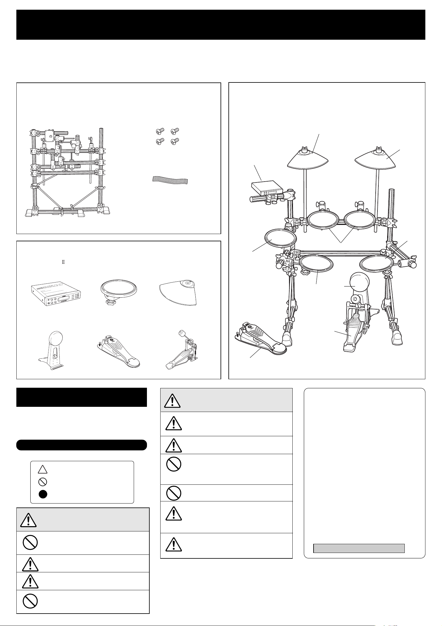
■RS65 梱包内容
RS65 総組立(開梱時) トラス小ネジM5x8
●パッド、ドラムトリガーモジュール類(別売品)
qDTXPRESS
ドラムトリガーモジュール
※ ラックを組み立てる前に、すべての部品がそろっ
ていることを確認してください。
(モジュールホルダー止めネジ x4)
ケーブルバンド(x10)
組立説明書(本紙)
wTP65/65S
ドラムパッド
ePCY65/65S
シンバルパッド
■RS65 +パッド類:セットアップ例
ePCY65S
e
q
w
w
w
rKP65
キックパッド
tHH65
ハイハットコントロールペダル
安全へのこころがけ
ご使用の前に、この『安全へのこころがけ』を
よくお読みのうえ正しくお使いください。
特にお子様には、最初にご家族の方、
または指導者から取扱い方法の指導をお願いいたします。
人身傷害の危険を防止するには
〜以下の指示を必ず守ってください〜
注意(危険・警告を含む)を促す
内容があることを告げるものです。
禁止の行為を告げるものです。
行為を強制したり指示する
内容を告げるものです。
この表示を無視して誤った取扱いをすると、
注意
フットスイッチやフットペダルの下に、手や足を入
れないでください。
挟まれてけがの原因となります。
クランプを調節する際、指に注意してください。
指が挟まれてけがをする恐れがあります。
人が傷害を負ったり、財産が損害を受ける危
険の恐れがある内容を示しています。
yフットペダル
※ FP-700 など
警告
t
この表示を無視して誤った取扱いをす
ると、人が死亡又は重傷を負う危険の
恐れがある内容を示しています。
設置場所は床面が平らで丈夫な所にしてくださ
い。床が傾いていたり、段差がありますと不安定
となり、転倒する恐れがあります。
固定用ネジはしっかり締め付けてください。
転倒、落下等によりけがの原因となります。
高さや角度の調整をおこなう際、急にネジを緩め
ないでください。パッドが落下したり、ラック、
パイプが滑り落ちて手や指を挟む等けがの原因と
なります。
ラックに腰かけたり踏み台にしないでください。転
倒したり壊れたりして、けがの原因となります。
小さなお子様が触ったり、近づく場合は注意して
ください。多くのパイプやアームが並びますの
で、動きによっては体をぶつけたりして、けがを
する恐れがあります。
パッドやモジュールのセッティングの際は、ケー
ブルの引きまわしに注意してください。
足を引っかけて転倒する恐れがあります。
wTP65S
r
y
■ ヤマハ株式会社 EM 営業統括部
各地区お問い合わせ先
●EM北海道
〒 064-8543札幌市中央区南 10 条西 1 丁目 1-50
TEL011(512)6113
●EM仙台
〒980-0804仙台市青葉区大町 2-2-10
TEL022(222)6147
●EM東京
〒 108-8568東京都港区高輪 2-17-11
TEL03(5488)5471
●EM名古屋
〒 460-8588名古屋市中区錦 1-18-28
TEL052(201)5199
●EM大阪
〒542-0081大阪市中央区南船場 3-12-9
TEL06(6252)5231
●EM九州
〒812-8508福岡市博多区博多駅前 2-11-4
TEL092(472)2130
ホームページ http://www.yamaha.co.jp/
パイプの端面や内面及びネジの先端にご注意くださ
い。尖った部分等で指にけがをする恐れがあります。
電子ドラムラックには、アコースティックドラムを
取り付けないでください。クランプの破損や、ドラ
ムの落下などで、けがをする恐れがあります。
*仕様および外観は改良のため予告なく変更する場合があります。
Page 2
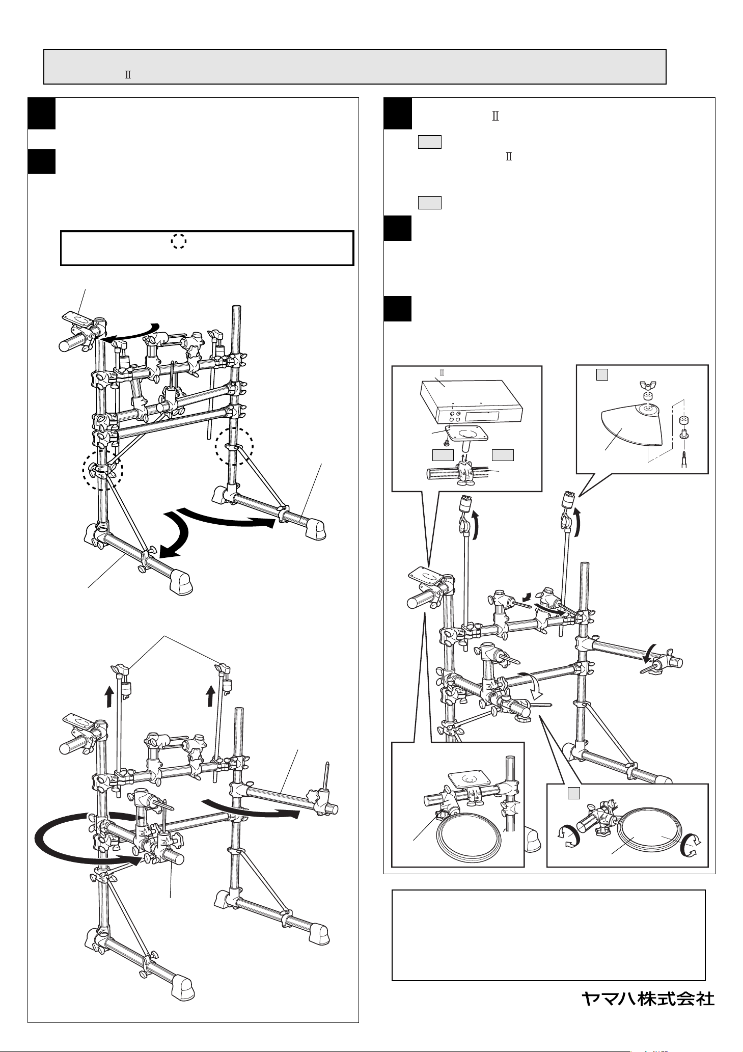
■RS65 組み立て手順
※RS65本体は各部品がすでに組まれた状態で梱包されています。箱から取り出しましたら、以下の手順に従って組立完成させてください。
DTXPRESS
を取り付ける際、ドライバー(+)を使用します。あらかじめご用意ください。
1
2
箱から取り出しましたら、全ての緩衝材を取り外します。
各部品のセットアップ
・下図を参考に動かす部分のボルトを緩め、セット完了しましたら
ボルトを締め付け固定します。
セットアップは q 〜 u の順番で進めます。
注意:セットアップ前に 印内のボルトをあらかじめ緩めてから
モジュールホルダー集成
行ってください。
e
3
4
5
DTXPRESS
DTXPRESSの取り付け
3-1 モジュールホルダーをホルダークランプより取り外し、
DTXPRESS
を付属のネジで取り付けます。
必ず付属のネジを使用してください。本体の落下や破損の原因
となります。
3-2 再度モジュールホルダーをホルダークランプに取り付けます。
シンバルパッドの取り付け
シンバルパッドをシンバルホルダーに取り付け、向きを調整し、固
定します。(取り付け方法は、シンバルパッドの取扱説明書をご参照
ください。)
ドラムパッドの取り付け
ドラムパッドを六角ロッドシリンダーに取り付け、向きを調整し、
固定します。
手順4
注意
→
左レッグ集成
注意
←
w
q
シンバルホルダー
rt
右レッグ集成
モジュール
ホルダー
手順3-1 手順3-2
ホルダー
クランプ
シンバル
パッド
y
サイドアーム(L)集成
サイドアーム(R)集成
u
ハイハット用ドラムパッドクランプは
こちらにも取り付けることが
できます。
手順5
ドラムパッド
クランプ
クランプやパッドなど各部の固定ネジはしっかりと締め付けてください。
緩かったり締めすぎたりすると、落下や破損の原因となります。ご注意く
ださい。
組み立てが完成したら、キックパッド、ハイハットコントロールペダルな
どをセットし、結線します。各ケーブルは、演奏のじゃまにならないよう
に、ケーブルバンドでパイプに固定しましょう。
一度セッティングされたものを動かす際も、必ずボルトを緩めてから行っ
てください。
ドラムパッド
EM 営業統括部企画推進室
TEL.03(5488)5445
V960280
Page 3

YAMAHA
Electronic Drum Rack System
RS65
Thank you for purchasing the Yamaha Electronic Drum Rack System RS65.
Before using, thoroughly read these assembly instructions, and use this product safely and correctly.
■ RS65 Rack Stand Parts
* Before assembling the rack stand, make sure all of the parts shown below
are included.
Overall Assembly RS65
(When the box is opened)
Small Screws M5 X8
(Module Holder Fixing Screws X4)
Cable Band (x10)
■ RS65+Pad
q
Assembly Instructions
grouping : Set up example
ePCY65S
e
Assembly Instructions
(this sheet)
● Pad and Drum Trigger Grouping (option)
qDTXPRESS
Drum Trigger Module
rKP65
Kick Pad
wTP65/65S
Drum Pad
tHH65
Hi-hat Control Pedal
ePCY65/65S
Cymbal Pad
yFoot Pedal
* FP-700 etc.
t
w
wTP65S
w
w
r
y
PRECAUTIONS
Before using, please read this “Assembly Instruction” sheet,
and use this product in a safe and proper manner.
Especially for children, parents or an instructor should teach the
children the proper manner in which to use the device.
Topreventagainstaccidentsandinjury
Pleasefollowthecautionslistedbelow
Caution (including danger, or warning). This mark indicates
cautions in which you should pay close attention to.
Acts indicated with this icon are prohibited and should not
be attempted.
This icon indicates acts that you are urged to follow.
●
* Specifications are subject to change without notice.
If this symbol is ignored and the equipment is
used improperly, fatal injury to persons or se-
WARNING
rious damage could occur.
Always set the instrument on a flat and solid surface.
Placement on a sloping, unstable surface or on steps
may result in the instrument being unstable and overturning.
Make sure all bolts are tightened firmly. Loose bolts
may result in the rack overturning or parts dropping
causing injury.
When adjusting the height or angle, do not suddenly
loosen the bolt. The pad may drop, the rack or pipes
may slip, pinching or causing injury to hands or fingers.
Do not sit or step on the rack. The rack may overturn
or be damaged resulting in injury.
Please be careful when children are close to or touching the product. The product has many pipes and arms
so careless movement around the product may result
in injury.
When setting the pads and modules, please pay close
attention in regards to the handling and setting of
cables. Feet may become entangled in the cables resulting in falls.
* Specifications are subject to change without notice.
CAUTION
If this symbol is ignored and the equipment is
used improperly, there is a danger of injury to
persons handling the equipment, and material
damage could occur.
Do not put your hands or feet under the foot pedal or
foot switch. They may be pinched resulting in injury.
Watch your fingers when adjusting clamps. They may
become pinched resulting in injury.
Be careful around pipe ends, inside the pipe and screw
ends. Metal shavings, etc. may injure your fingers.
Do not attach acoustic drums to the electronic drum
rack. Clamps may be damaged and drums may drop,
causing injury.
Page 4

■ RS65 Assembly
* Parts for the RS65's main structure have already been assembled before packing. After removing the unit from the box, follow
the instructions described below to complete the assembly.
A Phillips (+) screwdriver is required when attaching the DTXPRESS module. Please prepare one before starting assembly.
1
2
After removing the unit from the box, remove all cushion material.
Setting up the parts
• Loosen the bolts on the movable arms and legs, as shown in the diagrams below, then secure the bolts firmly once setting is complete.
Follow the setup order (q-u) in the diagrams shown below.
Caution : Make sure the bolts marked with a " " are loosened before
setting up.
Module Holder Assembly
e
3
4
5
DTXPRESS
Attaching the DTXPRESS
3-1 Remove the module holder from the holder clamp, and use the
supplied screws to attach the DTXPRESS
Make sure only the supplied screws are used. Using any other
screws may result in the unit falling off the holder or damage.
3-2 Reattach the module holder to the holder clamp.
.
Attaching the cymbal pads
Attach the cymbal pads to the cymbal holders and adjust their position,
then secure in place. (Please refer to the Owner's Manual that came
with the cymbal pads on attaching the cymbal pads.)
Attaching the drum pads
Attach drum pads to the hexagonal rod cylinder and adjust their position, the secure in place.
Step 4
Caution
^
Left Leg Assembly
Caution
$
Right Leg Assembly
w
q
Cymbal Holder
rt
Module
Holder
Step 3-1
Step 3-2
Holder
Clamp
Cymbal Pad
y
Side Arm (L) Assembly
Side Arm (R) Assembly
u
The hi-hat drum pad clamp can
also be attached to this arm.
Step 5
Drum Pad
Clamp
Drum Pad
Make sure all bolts on clamps, pads, etc., are firmly tightened.
Loose or over-tightened bolts may result in the part falling off and/or damage. Please use caution.
After assembly is complete, setup the kick pad, hi-hat control pedal, etc., and
connect the cables. Use the supplied cable bands to secure the cables to the
frame pipes to keep cables out of the way during performance.
If the rack is moved even after setup is complete, make sure the bolts are
loosened before moving the rack.
PrintedinIndonesia
 Loading...