

Page 1

|-1Т-Т1121^^И
ШЁжтлл^
Page 2

A WARNING
The engine exhaust from this product
contains chemicais known to the
State of Caiifornia to cause cancer, birth
defects or other reproductive harm.
YAMAHA
PW80T
OWNER'S SERVICE MANUAL
©2004 by Yamaha Motor Corporation, U.S.A.
1st Edition, April 2004
All rights reserved. Any reprinting or
unauthorized use without the written
permission of Yamaha Motor Corporation
U.S.A. is expressly prohibited.
Printed in Japan.
P/N. LIT-11626-18-30
LIT-CALIF-65-01
Page 3

NOTICE
Some data in this manual may become outdated due to improvements made to this model in
the future. If there is any question you have regarding this manual or your machine, please con
sult your Yamaha dealer.
INTRODUCTION
Congratulations on your purchase of the Yamaha PW80.
This model represents the product of many years of Yamaha experience in the production of fine
sporting, touring, and pacesetting racing machines. You can now appreciate the high degrees
of craftsmanship and reliability that have made Yamaha a leader in these fields. This manual will
provide you with a good basic understanding of the features, operation, and basic maintenance
and inspection items of this vehicle. If you have any questions regarding the operation or main
tenance of your machine, please consult your Yamaha dealer.
Particularly important information is distinguished in this manual by the following notations:
The Safety Alert Symbol means ATTENTION! BECOME ALERT! YOUR
^ SAFETY IS INVOLVED!
A WARNING
NOTE:
Failure to follow WARNING instructions could result in severe injury or
death to the machine operator, a bystander, or a person inspecting or repair
ing the machine.
A CAUTION indicates special precautions that must be taken to avoid
damage to the machine.
A NOTE provides key information to make procedures easier or clearer.
Page 4

A WARNING
READ THIS MANUAL CAREFULLY FOR INSTRUCTIONS ON HOW TO
PROPERLY OPERATE THIS MACHINE.
ADULT INSTRUCTION AND SUPERVISION ARE REQUIRED.
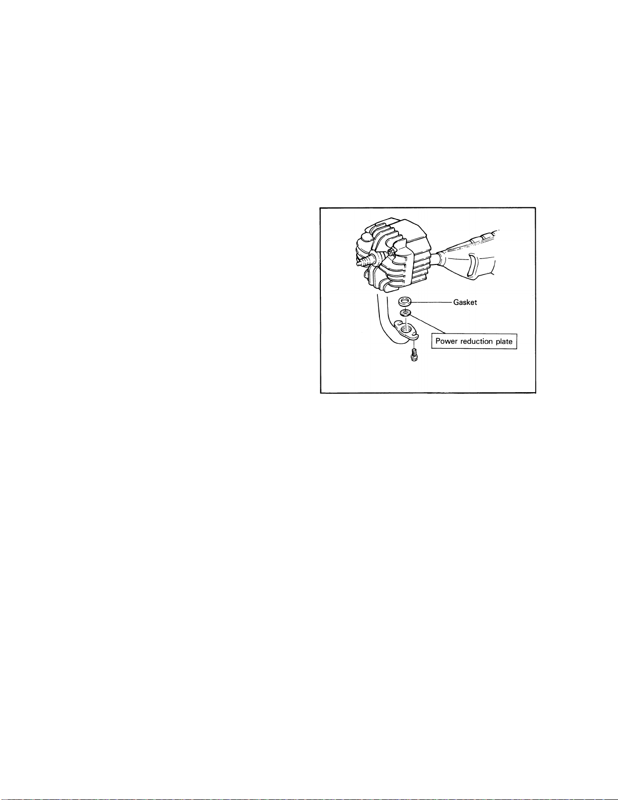
THIS MODEL IS PROVIDED WITH A POWER REDUCTION PLATE FOR THE BE
GINNING RIDER. DO NOT REMOVE THESE ITEMS UNTILTHE ADULT SUPERVISIOR HAS JUDGED THE RIDER TO BE PROFICIENT.
WEIGHT OF THE RIDER SHOULD NOT EXCEED 40 kg (88 lb).
ALWAYS WEAR A HELMET AND SUITABLE PROTECTIVE CLOTHING
WHEN RIDING.
DO NOT TOUCH ANY MOVING PARTS OR HEATED AREAS.
ALWAYS PERFORM PRE-OPERATION CHECKS. REFER TO PAGE 5.
THIS MACHINE IS DESIGNED TO CARRY THE OPERATOR ONLY. NO
PASSENGERS.
THIS MACHINE IS DESIGNED FOR OFF-ROAD USE ONLY. IT IS NOT
SUITABLE FOR ON-ROAD USE.
IMPORTANT NOTICE
This machine is designed for off-road use only by young operators under adult instruction
and supervision. It is illegal for this machine to be operated on any public street, road, or
highway. Off-road use on public lands may be illegal. Please check local regulations before
riding.
A SAFETY INFORMATION
GASOLINE IS HIGHLY FLAMMABLE:
* Always turn off the engine when refueling.
* Take care not to spill on the engine or exhaust pipe/muffler, when refuel
ing.
* Never refuel while smoking or in the vicinity of an open flame.
If you should swallow some gasoline or inhale a lot of gasoline vapor, or
allow some gasoline to get in your eye(s), see your doctor immediately. If
any gasoline spills on your skin or clothing, immediately wash it with soap
and water, and change your clothes.
Always turn off the engine before leaving the machine unattended. When
parking the machine, note the following:
* The engine and exhaust pipe(s)/muffler(s) may be hot. Park the machine
in a place where pedestrians or children are not likely to touch the
machine.
* Do not park the machine on a slope or soft ground; the machine may over
turn.
When transporting the machine in another vehicle, be sure it is kept upright
and that the fuel cock is turned to the "OFF". If it should lean over, gasoline
may leak out of the carburetor or fuel tank.
5.
Never start your engine or let it run for any length of time in a closed area.
The exhaust fumes are poisonous and may cause loss of consciousness and
death within a short time. Always operate your machine in an area with ade
quate ventilation.
Always wear a helmet, gloves, boots, trousers, and jacket for motocross
6.
riding.
Page 5
FOR THE PARENTS
Since this model is intended for beginning riders, it is equipped with an safety device
that let you limit the operating speed of the machine; the power reduction plate. It limits
the output of the engine.
As your child's riding skills improve, you can remove the power reduction plate. Since
removal of this plate will result in a significant increase in power.
Please use this safety device to match the machine's output to your child's riding skills.
• A power reduction plate is provided in the
cylinder exhaust port. Removal of this plate
adds to the vehicle output power.
Page 6

OFF-ROAD MOTORCYCLE LIMITED WARRANTY
Yamaha Motor Corporation, U.S.A. hereby warrants
that each new Yamaha off-road motorcycle purchas
ed from an authorized Yamaha motorcycle dealer in the
continental United States will be free from defects in
material and workmanship for the period of time stated
herein, subject to certain stated limitations.
THE PERIOD OF WARRANTY for Yamaha off-road
motorcycles shall be ninety (90) days from the date
of purchase, with no mileage limitation.
MODELS EXCLUDED FROM WARRANTY include
those machines used for non-Yamaha-authorized ren
ting, leasing, or other commercial purposes.
DURING THE PERIOD OF WARRANTY any authorized
Yamaha motorcycle dealer will, free of charge, repair
or replace, at Yamaha's option, any part adjudged
defective by Yamaha due to faulty workmanship or
material from the factory. Parts used in warranty
repairs will be warranted for the balance of the pro
duct's warranty period. All parts replaced under war
ranty become property of Yamaha Motor Corporation
U.S.A.
GENERAL EXCLUSIONS from this warranty shall
include any failures caused by:
a. Competition or racing use (except TY models used
for sanctioned trials).
b. Installation of parts or accessories that are not
qualitatively equivalent to genuine Yamaha parts.
c. Abnormal strain, neglect, or abuse.
d. Lack of proper maintenance.
e. Accident or collision damage.
f. Modification to original parts.
g. Damage due to improper transportation.
YAMAHA MOTOR CORPORATION, U.S.A.
SPECIFIC EXCLUSIONS from this warranty shall
include parts replaced due to normal wear or routine
maintenance.
THE CUSTOMER'S RESPONSIBILITY under this war
ranty shall be to:
1. Operate and maintain the motorcycle as specified
in the appropriate Owner's Manual, and
2. Give notice to an authorized Yamaha motorcycle
dealer of any and all apparent defects within ten
(10) days after discovery, and make the machine
available at that time for inspection and repairs at
such dealer's place of business.
WARRANTY TRANSFER: To transfer the warranty
from the original purchaser to any subsequent pur
chaser, it is imperative that the machine be inspected
and registered for warranty by an authorized Yamaha
motorcycle dealer. In order for this warranty to remain
in effect, this inspection and registration must take
place within ten (10) days after transfer. An inspec
tion and registration fee will be charged for this service.
YAMAHA MOTOR CORPORATION, U.S.A. MAKES NO
OTHER WARRANTY OF ANY KIND, EXPRESSED OR
IMPLIED. ALL IMPLIED WARRANTIES OF
MERCHANTABILITY AND FITNESS FOR A
PARTICULAR PURPOSE WHICH EXCEED THE
OBLIGATIONS AND TIME LIMITS STATED IN THIS
WARRANTY ARE HEREBY DISCLAIMED BY YAMAHA
MOTOR CORPORATION, U.S.A. AND EXCLUDED
FROM THIS WARRANTY.
SOME STATES DO NOT ALLOW LIMITATIONS ON
HOW LONG AN IMPLIED WARRANTY LASTS, SO THE
ABOVE LIMITATION MAY NOT APPLY TO YOU. ALSO
EXCLUDED FROM THIS WARRANTY ARE ANY
INCIDENTAL OR CONSEQUENTIAL DAMAGES
INCLUDING LOSS OF USE. SOME STATES DO NOT
ALLOW THE EXCLUSION OR LIMITATION OF
INCIDENTAL OR CONSEQUENTIAL DAMAGES, SO
THE ABOVE EXCLUSION MAY NOT APPLY TO YOU.
THIS WARRANTY GIVES YOU SPECIFIC LEGAL
RIGHTS, AND YOU MAY ALSO HAVE OTHER RIGHTS
WHICH VARY FROM STATE TO STATE.
YAMAHA MOTOR CORPORATION, U.S.A.
P. O. Box 6555
Cypress, California 90630
WARRANTY QUESTIONS AND ANSWERS CUSTOMER SERVICE
Q. What costs are my responsibility during the warranty period?
A. The customer's responsibility includes all costs of normal maintenance services, non
warranty repairs, accident and collision damage, and oil, oil filters, air filters, spark
plugs, and brake shoes or pads.
Q. What are some examples of "abnormal" strain, neglect, or abuse?
A. These terms are general and overlap each other in areas. Specific examples include:
Running the machine out of oil; sustained high-rpm, full-throttle use; operating the
machine with a broken or damaged part which causes another part to fail; damage
or failure due to improper or careless transporation and or tie down; and so on. If
you have any specific questions on operation or maintenance, please contact your
dealer for advice.
Q. Does the warranty cover incidental costs such as towing or transportation due to
a failure?
A. No. The warranty is limited to repair of the machine itself.
Q. May I perform any or all of the recommended maintenance shown in the Owner's
Manual instead of having the dealer do them?
A. Yes, if you are a qualified mechanic and follow the procedures specified in the Owner's
and Service Manual. We do recommend, however, that items requiring special tools
or equipment be done by a Yamaha motorcycle dealer.
Q. Will the warranty be void or cancelled if I do not operate or maintain my new
motorcycle exactly as specified in the Owner's Manual?
A. No. The warranty on a new motorcycle cannot be "voided" or "cancelled." However,
if a particular failure is caused by operation or maintenance other than as shown
in the Owner's Manual, that failure may not be covered under warranty.
Q. What responsibility does my dealer have under this warranty?
A. Each Yamaha motorcycle dealer is expected to:
1. Completely set up every new machine before sale.
2. Explain the operation, maintenance, and warranty requirements to your satisfation at the time of sale, and upon your request at any later date.
In addition, each Yamaha motorcycle dealer is held responsible for his setup, service
and warranty repair work.
Q. Is the warranty transferable to second owners?
A. Yes. The remainder of the existing warranty can be transferred upon request. The
unit has to be inspected and re-registered by an authorized Yamaha motorcycle dealer
for the warranty coverage to remain effective.
If your machine requires warranty service, you must take it to any authorized
Yamaha motorcycle dealer within the continental United States. Be sure to
bring your warranty registration identification or other valid proof of the
original date of purchase. If a question or problem arises regarding warranty,
first contact the owner of the dealership. Since all warranty matters are
handled at the dealer level, this person is in the best position to help you.
If you are still not satisfied and require additional assistance, please write:
YAMAHA MOTOR CORPORATION U.S.A.
CUSTOMER RELATIONS DEPARTMENT
When contacting Yamaha Motor Corporation, U.S.A. don't forget to include
any important information such as names, addresses, model, V.I.N. (frame
number), dates, and receipts.
The federal government requires each manufacturer of a motor vehicle to
maintain a complete, up-to-date list of all first purchasers against the
possibility of a safety-related defect and recall. This list is compiled from
the purchase registrations sent to Yamaha Motor Corporation, U.S.A. by the
selling dealer at the time of your purchase.
If you should move after you have purchased your new motorcycle, please
advise us of your new address by sending a postcard listing your motorcycle
model name, V.I.N. (frame number), dealer number (or dealer's name) as it is
shown on your warranty identification, your name and new mailing address.
Mail to :
YAMAHA MOTOR CORPORATION, U.S.A.
This will ensure that Yamaha Motor Corporation, U.S.A. has an up-to-date
registration record in accordance with federal law.
P.O. Box 6555
Cypress, California 90630
CHANGE OF ADDRESS
WARRANTY DEPARTMENT
P.O. Box 6555
Cypress, California 90630
Page 7
A SAFETY INFORMATION
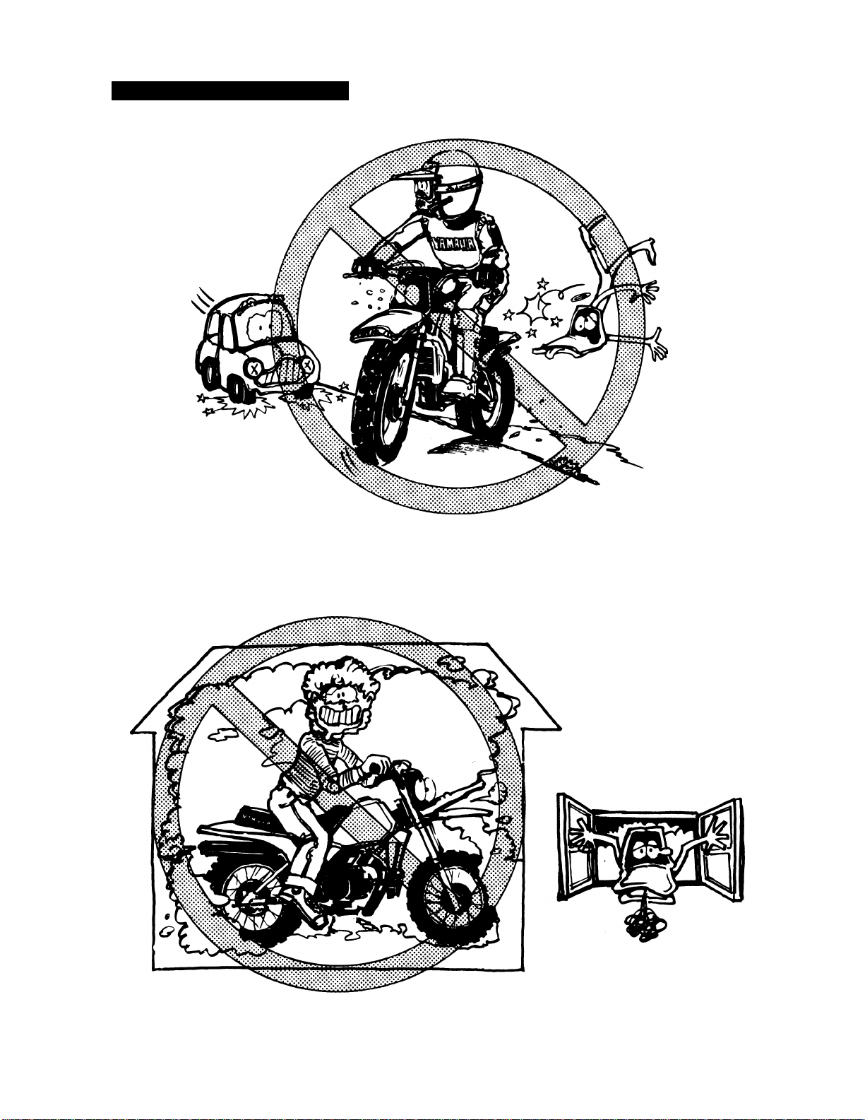
1. Don't ride it on the street.
2. Don't run the engine inside a building.
Page 8

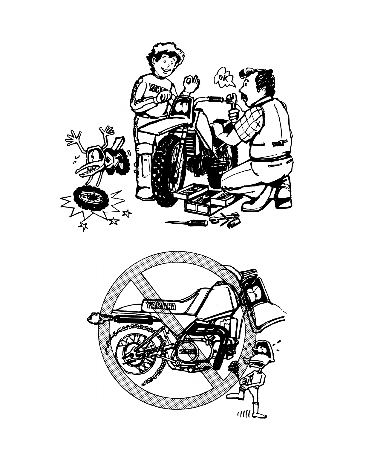
3. This is a one-seater motorbike. Don't give any person a ride.
4. Let's learn how to ride properly. Ask your parents for any question.
Page 9

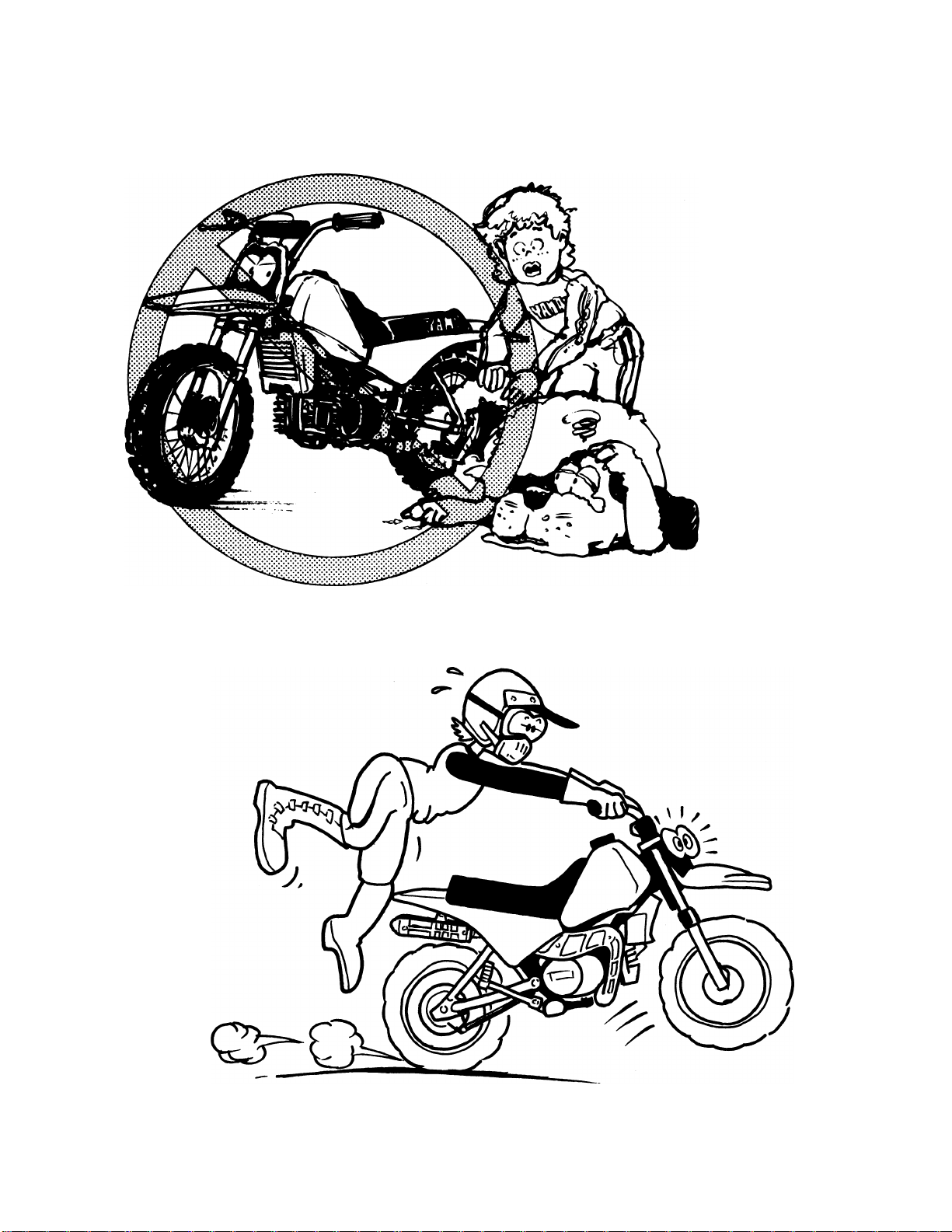
5. When riding the machine, be sure to wear a helmet as illustrated.
Long sleeved trainer
Motocross pants
Boots
Helmet
Goggles
Mouth guard
Gloves
6. When going for riding, be sure to be with your family. Never go alone.
Page 10
7. Before riding the machine, ask your parents to check the machine very carefully.
8. Don't touch the areas shown below, or you'll get burnt in the hand.
Page 11
9. Don't touch rotating or moving parts.
10. Before starting the engine, be sure to shift the transmission into neutral.
Page 12

CONTENTS
GENERAL INFORMATION.........................................................................................................................1
DESCRIPTION....................................................................................................................................1
MACHINE IDENTIFICATION .............................................................................................................1
CONTROL FUNCTIONS ....................................................................................................................2
FUEL AND OIL....................................................................................................................................3
PRE-OPERATION CHECKS...............................................................................................................5
STARTING AND OPERATION ..........................................................................................................6
PERIODIC MAINTENANCE AND ADJUSTMENT .. .
MAINTENANCE AND LUBRICATION SCHEDULE CHART
SPECIAL TOOLS .............................................................................................................................. 8
ADJUSTMENT...................................................................................................................................10
MAINTENANCE AND MINOR REPAIRS..................................................................................................19
PREPARATION FOR SERVICE.......................................................................................................19
ENGINE..............................................................................................................................................19
CHASSIS ......................................................................................................................................... 31
MISCELLANEOUS................................................................................................................................... 37
ELECTRICAL COMPONENTS AND WIRING DIAGRAM...............................................................37
TROUBLESHOOTING......................................................................................................................40
CLEANING AND STORAGE ...........................................................................................................41
SPECIFICATIONS.............................................................................................................................42
CABLE ROUTING.............................................................................................................................50
NOISE REGULATION............................................................................................................................... 52
MAINTENANCE RECORD ........................................................................................................................52
...................
............................................................
............................................................
7
7
Page 13
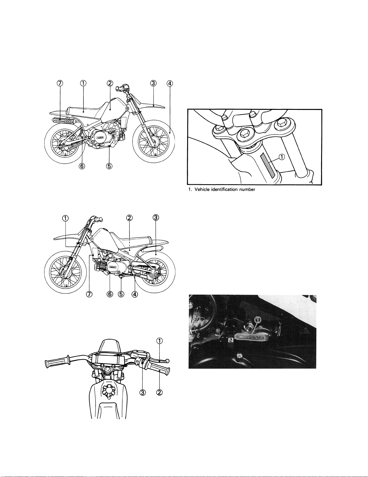
GENERAL INFORMATION
1. Seat
2. Fuel tank
3. Front fender
4. Front wheel
DESCRIPTION
5. Brake pedal
6. Kick starter
7. Muffler
MACHINE
IDENTIFICATION
VEHICLE IDENTIFICATION NUMBER
The vehicle identification number is stamped
into the steering head pipe.
NOTE:
The vehicle identification number is used to
identify your machine and may be used to
register your machine with the licensing
authority in your state.
--------------------------------------
1. Front fork
2. Monocross suspension
3. Rear wheel
4. Sidestand
1. Front brake lever
2. Throttle grip
3. "ENGINE STOP" switch
ENGINE SERIAL NUMBER
The engine serial number is stamped on the left
side of the engine on top of the crankcase.
5. Footrest
6. Shift pedal
7. Air filter
1. Engine serial number
NOTE:
The first digits of these numbers are for model
identifications; the remaining digits are the unit
production number.
Keep a record of these numbers for reference
when ordering parts from a Yamaha dealer.
-1-
Page 14
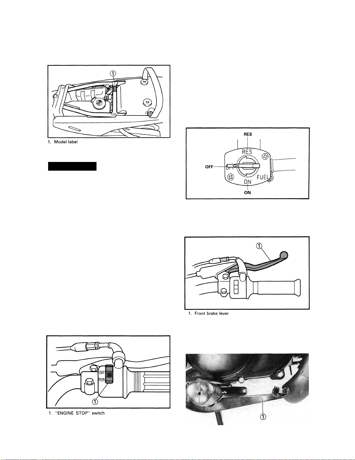
MODEL LABEL
The model label (T) is affixed to the frame
under the rider's seat. This information will
be needed to order spare parts.
CONTROL FUNCTIONS
A WARNING
Before riding this machine, become tho
roughly familiar with all operating controls
and their function.
Consult a Yamaha dealer or other qualified
mechanic regarding any control or func
tion you do not thoroughly understand.
I— NOTICE:
This machine is designed strictly for
competition use only. It is not equipped
with highway approved lighting. Off
road use on public land may be illegal.
--------------------------------------------
OFF: With the lever in this position, fuel will
not flow. Always return the lever to this
position when the engine is not running.
ON: With the lever in this position, fuel flows
to the carburetor. Normal riding is done
with the lever in this position.
RES: This indicates reserve. If you run out of
fuel while riding, move the lever to this
position. FILL THE TANK AT THE
FIRST OPPORTUNITY. BE SURE TO
SET THE LEVER TO "ON" AFTER
REFUELING.
FRONT BRAKE LEVER
The front brake lever is located on the right
handlebar, pull it toward the handlebar to ac
tivate the front brake.
"ENGINE STOP" SWITCH
Make sure that the engine stop switch is posi
tioned to "RUN". The engine switch has been
equipped to ensure safety in an emergency
such when the machine is upset or trouble
takes place in the throttle system. The engine
will not start or run when the engine stop
switch is turned to "OFF".
FUEL COCK
The fuel cock supplies fuel from the tank to car
buretor while filtering the fuel. The fuel cock
has the three positions;
REAR BRAKE PEDAL
The rear brake pedal is on the right side of the
machine. Press down on the brake pedal to ac
tivate the rear brake.
1. Rear brake pedal
2-
Page 15
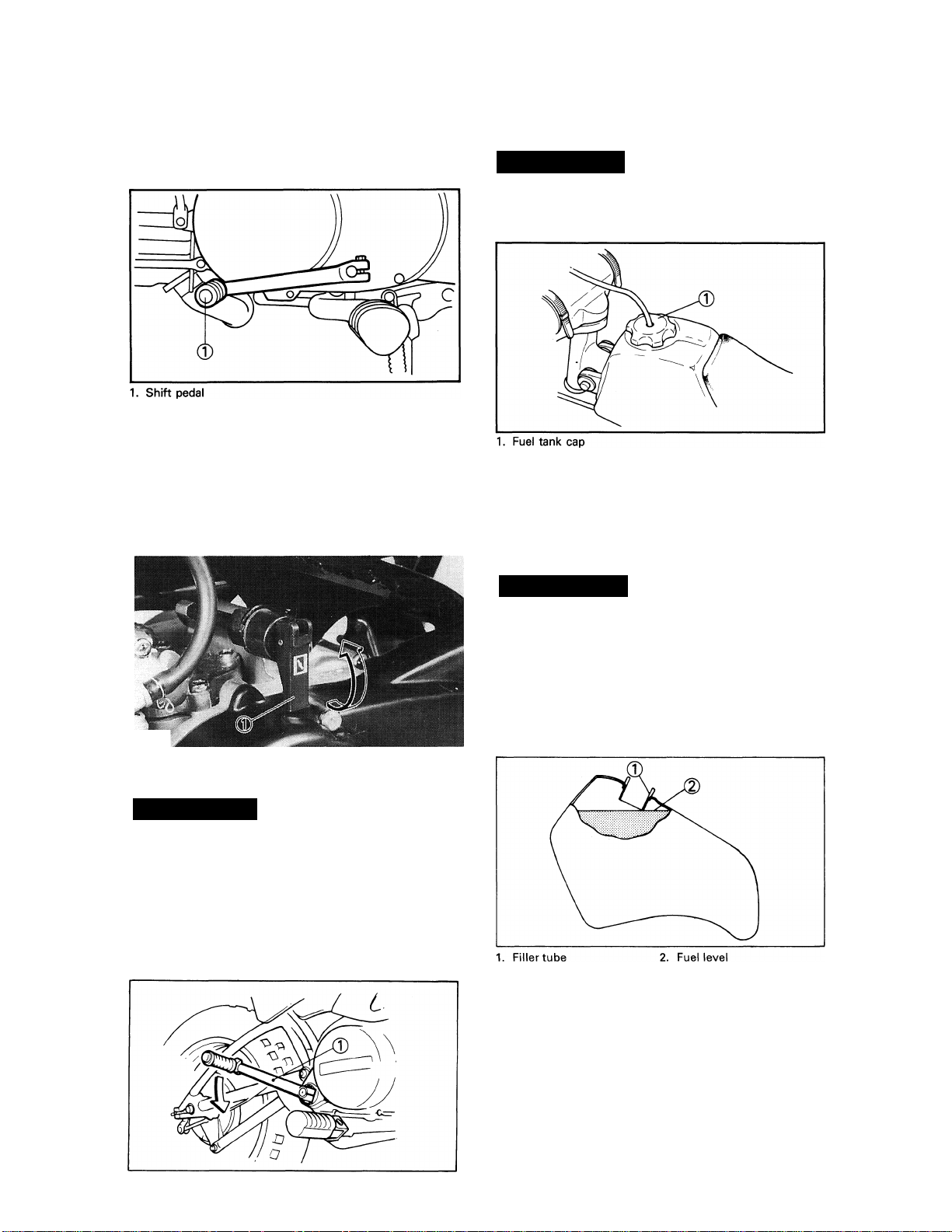
SHIFT PEDAL
The gear ratios of the constant mesh 3-speed
transmission are ideally spaced. The gears can
be shifted by using the shift pedal on the left
side of the engine.
STARTER LEVER (CHOKE)
When cold, the engine requires a richer air/fuel
mixture for starting. A separate starter circuit,
which is controlled by the starter lever, sup
plies this mixture.
Pull the lever out to open the circuit (for star
ting) and push the lever in to close the circuit.
FUEL TANK CAP
Remove the fuel tank cap by turning counter
clockwise.
▲ warning
Do not overfill the fuel tank. Avoid spill
ing fuel on the hot engine.
FUEL AND OIL
FUEL
Use regular gasoline. Always use fresh, name
brand gasoline.
1. Starter lever
KICK STARTER
▲WARNING
Before starting the engine, be sure to
shift the transmission into neutral.
Rotate the kick starter 0 away from the en
gine. Push the starter down lightly with your
foot until the gears engage, then kick
smoothly and forcefully to start the engine.
▲ warning
Do not overfill the fuel tank. Avoid spill
ing fuel on the hot engine. Do not fill the
fuel tank above the bottom of the filler
tube as shown in the illustration or it may
overflow when the fuel heats up later and
expands.
Recommended fuel:
UNLEADED GASOLINE ONLY
Fuel tank capacity:
Total:
4.9 L (1.08 Imp gal, 1.29 US gal)
Reserve:
1.0 L (0.22 Imp gal, 0.26 US gal)
1. Kickstarter
-3-
Page 16
Your Yamaha engine has been designed to use
regular unleaded gasoline with a pump octane
number ([R + M]/2) of 86 or higher, or research
octane number of 91 or higher. If knocking or
pinging occurs, use a different brand of gaso
line or premium unleaded fuel. Unleaded fuel
will give you longer spark plug life and reduced
maintenance cost.
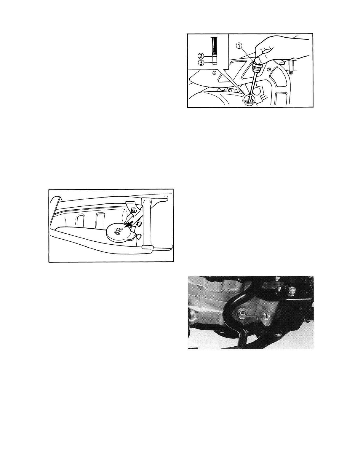
ENGINE OIL (OIL TANK)
Make sure there is sufficient engine oil in the
oil tank. If necessary add oil.
Recommended oil:
Yamalube 2-S or air-cooled
2-stroke engine oil
Oil tank capacity:
0.95 L (0.84 Imp qt, 1.00 US qt)
1. Dip stick
2. Maximum level
3. Minimum level
Recommended oil
Yamalube 4 (10W30)
or SAE 10W30 type SE motor oil
Oil capacity:
Total amount:
0.75 L (0.66 Imp qt, 0.79 US qt)
Periodic oil change:
0.65 L (0.57 Imp qt, 0.69 US qt)
The dip stick has a Minimum and Maximum
mark, and the oil level should be between the
two. If the level is lower, then and sufficient
oil to raise it to the proper level.
On the bottom of the engine there is a drain
plug. Remove it and drain all the transmission
oil out. Reinstall the drain plug (make sure it
is tight). Add oil through the dip stick hole.
TRANSMISSION OIL
The only servicing for you to do is to check and
fill the transmission lubricating oil. The trans
mission dip stick is located right above the kick
starter. To check the level, warm the engine
up for several minutes, screw the dip stick com
pletely out and then just rest the stick in the
hole.
NOTE:
When checking transmission oil level with the
dip stick, let the unscrewed dip stick just rest
on the case threads. Also, be sure the machine
is positioned straight up.
------------------------------------------
1. Drain plug
Drain plug torque:
20 Nm (2.0m*kg, 14fHb)
NOTE: ______________________________
Do not add any chemical additives. Transmis
sion oil also lubricates the clatch and additives
could cause the clutch to slip.
-4-
Page 17
PRE-OPERATION CHECKS
Item
Brake
Transmission oil
Drive chain
Spark plug
Throttle Check for proper throttle cable operation
Air filter
Wheels and tires
Fittings/fasteners
Check operation/adjustment
Change oil as required
Check alignment/ adjustment/ lubrication
Check color/condition
Foam type — must be clean and damp w/oil always 11^12
Check pressure/runout/spoke tightness/bead stopper/axle nuts
Check all — tighten as necessary
NOTE:______________________________________________________________________
Pre-operation checks should be made each time the machine is used. Such an inspection can
be thoroughly accomplished in a very short time; and the added safety it assures is more than
worth the time involved.
Routine Page
5, 14
4
15
10
5, 12
5, 16,31 ~ 34
5, 46, 47, 49
A WARNING
If any item in the PRE-OPERATION CHECK is not working properly, have it inspected
and repaired before operating the machine.
BRAKE (FRONT AND REAR)
Check for correct play in the brake lever and
pedal and make sure they are working proper
ly. Check the brakes at tow speed shortly after
starting out. If the play is correct, make an
adjustment.
WHEEL
Check the wheel runout and damage, and
check the tightness of spokes.
TIRES
Check the tire pressure and check the tires for
wear.
Front
Rear
100 kPa (1.0 kgf/cm^ 15 psi)
100 kPa (1.0 kgf/cm', 15 psi)
THROTTLE GRIP
Turn the throttle grip to see that it operates pro
perly and that the play is normal. Make certain
the throttle springs are closed when released.
"ENGINE STOP" SWITCH
Start the engine and make sure the "ENGINE
STOP" switch functions properly.
FITTINGS/FASTENERS
Always check the tightness of chassis fittings
and fasteners before a ride. Use the chart on
page 46, 47 and 49 to find the correct torque.
-5-
Page 18

STARTING AND
OPERATION
CAUTION:
Prior to operating the machine, perform
steps listed in pre-operation check list.
A WARNING
Never start your engine or let it run for any
length of time in a closed area. The ex
haust fumes are poisonous and can cause
loss of consciousness and death within a
short time. Always operate your machine
in an area with adequate ventilation.
STARTING A COLD ENGINE
AWARNING
Before starting the engine, be sure to
shift the transmission into neutral.
1. Turn the fuel cock to "ON".
2. Operate the starter (choke) and complete
ly close the throttle grip.
3. Slide the "ENGINE STOP" switch to the
"RUN".
4. Kick the kick starter with full strength to
start the engine.
5. After the engine starts, warm up for one
or two minutes. Make sure the starter
(choke) is returned to the original position
before riding.
STARTING A WARM ENGINE
To start a warm engine, refer to the "Starting
a cold engine" section. The starter (choke)
should not be used. The throttle should be
opened slightly.
CAUTION:
See "Break-in Section" prior to operating
engine for the first time.
WARMING UP
To get maximum engine life, always "warm
up" the engine before starting off. Never ac
celerate hard with a cold engine! To see
whether or not the engine is warm, see if it
responds to throttle normally with the starter
(choke) turned off.
A WARNING
Before starting off, be sure to turn up or
remove the side stand.
Failure to retract the side stand completely
can result in a serious accident when you
try to turn a corner.
ENGINE BREAK-IN
1. Prior to starting, fill fuel tank with gasoline
and oil tank with specified oil.
2. Allow engine to warm up. Check engine
idling speed. Check operating controls
and engine stop switch operation.
3. Operate machine is lower gears at
moderate throttle setting for 3 — 5 min
utes. Check spark plug condition.
4.
Allow engine to cool. Repeat procedure,
running for 5 minutes. Very briefly, shift
to higher gears and check full throttle
response. Check spark plug condition.
5.
Allow engine to cool. Repeat procedure,
running for 5 minutes. Full throttle and
higher gears may be used, but avoid sus
tained full throttle operation. Check spark
plug condition.
6.
Allow engine to cool. Remove top end
and inspect. Remove "high" spots on
piston with No. 600 grit, wet sandpaper.
Clean, and carefully reassemble.
7.
Check entire unit for loose or misadjusted
fittings/controls/fasteners.
8.
Re-start engine and check through entire
operating range thoroughly. Stop. Check
spark plug condition. Re-start. After 10 ~
15 minutes operation, machine is ready
to ride.
-6-
Page 19

PERIODIC MAINTENANCE AND
ADJUSTMENT
MAINTENANCE AND LUBRICATION SCHEDULE CHART
The maintenance and lubrication schedule chart should be considered strictly as a guide to general
maintenance and lubrication intervals. You must take into consideration that weather, terrain,
geographical locations, and a variety of individual uses all tend to demand that each owner alter
this time schedule to match his environment. For example, if the machine is continually operated
in an area of high humidity then all parts must be lubricated much more frequently that shown
on the chart to avoid rust and damage. If you are in doubt as to how closely you can follow these
time recommendations, check with the Yamaha dealer in your area.
Lubrication intervals
Item
Transmission oil change
Drive chain
Con trol cables All apply thoroughly
Throttle grip and housing App ly lig htly
Brake pe dal shaft
Stand sh aft pivot
Front forks
Steering ball race
Wheel bearings Do not over-p ack yearly or...
Warm en gine before draining
Lub e/Adjust as req uired
Rem ove/ Clea n / Lube/ Adjust
App ly lig htly
App ly lig htly
Drain completely
Inspect thoroughly / Pack
moderately
Rem arks
Yam alub e 4-cycle oil or SAE 10W30
type SE motor oil
Yam alub e Chain and Cable L ube or
SAE 10W 30 m otor oil
Yam aha Cable Lub e or WD-40
Yam aha Cable Lub e or WD-40
Yam aha Cable Lub e or WD-40
Yam aha Cable Lub e or WD-40
Yam aha fork oil 20 wt or equivalent
Medium-weight wh eel bearin g grease
Medium-weight wh eel bearin g grease
Periodic maintenance intervals
Item
Brake sy stem (com plete)
Clutch
Spa rk plug
Spa rk arrester
Wheels and tires
Fittings and fasten ers
Drive chain
Air filter Wet type — clean / Replace as required (No .2)
Fue l cock
Ignition timing
Autolube pum p
Carburetor ad justm ent Chec k / operation / Timings
Carburetor overhaul
Cylinder compression Preventive maintenance check
Dec arbonize e ngin e
Che ck / Adjust as required — repair as required
Che ck / Adjust as required
Inspect / Clean or replace as requ ired
Clean
Pressure / Runout / Spoke — tension
Tighten before eac h trip and / or
Ten sion / Alig nment (No.1)
Clean / F lush tank as require d
Adjust / Clean or replac e as required
Che ck / Adjust / Air bleeding
Clean / R epair as required / Refit / Adjust
Includes exhaust s ystem
Rem arks
Typ e
Initial (hour)
10 20 40
O
O O
See service notes
o
o
The reafter
every (hour)
80 4 0 80 160
O
o o
o o
o
o
o
o
o o
o
o O o
Initial (hour)
10 20 40 80 40 80 160
o o O
o o o
O o o o
O o o o
o o o o
o o o o
o o o o
o o o
o o o o
o o o o
o o
o
o o o o
o o
The reafter
every (hour)
o
o
o
o
SERVICE NOTES:_____________________________________________________________
No. 1. DRIVE CHAIN: In addition to tension and alignment, chain must be lubricated every 0.5-1.0
hour. If unit is subjected to extremely hard usage and wet weather riding, chain must
be checked constantly. See "Lubrication Intervals" for additional details.
No. 2. AIR FILTER: Remove and clean filter every 20 - 40 hours.
-7-
Page 20
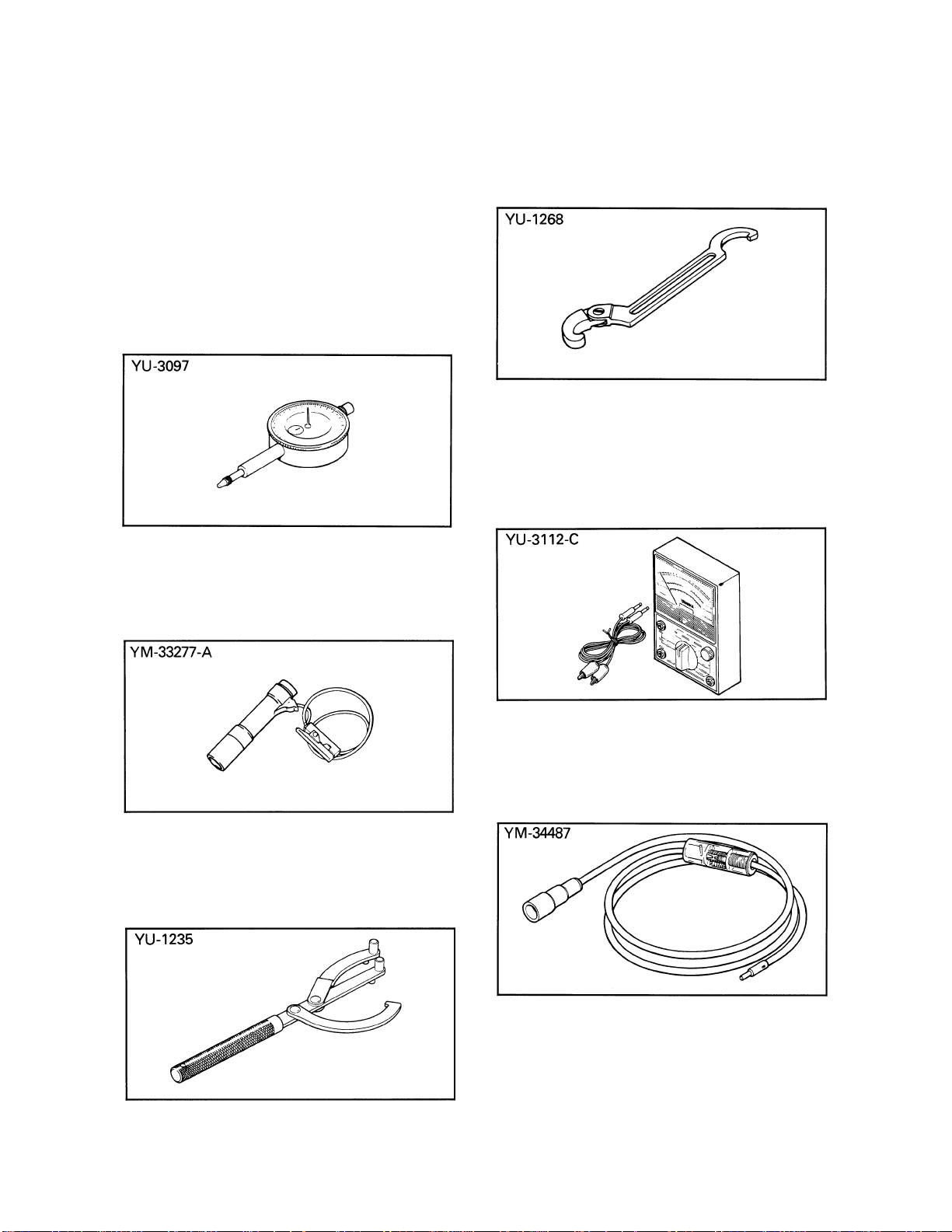
SPECIAL TOOLS
The following special tools are required to per
form maintenance, adjustments, and repairs on
your machine. These tools can be obtained
through your Yamaha dealer.
FOR ENGINE SERVICE
1. Dial Gauge
P/N. YU-3097
This tool is used for adjusting the oil pump
stroke.
FOR CHASSIS SERVICE
1. Ring Nut Wrench
P/N. YU-1268
This tool is used to loosen or tighten the steer
ing ring nut.
FOR ELECTRICAL SERVICE
1. Yamaha Pocket Tester
P/N. YU-3112-C
Use this tool to inspect the coil resistance, out
put voltage and amperage.
2. Inductive Timing Light
P/N. YM-33277-A
This tool is necessary for checking the ignition
timing.
3. Rotor Holding Tool
P/N. YU-1235
This tool is used when loosening or tightening
the flywheel magneto securing nut.
2. Dynamic Spark Tester
P/N. YM-34487
This instrument is necessary for checking the
ignition system components.
Page 21

LUBRICATION
-9-
Page 22

ADJUSTMENT
A WARNING
The engine, exhaust pipe(s), and muffler(s)
will be very hot after the engine has been
run. Be careful not to touch them or to
allow any clothing item to contact them
during inspection or repair.
SPARK PLU^
Standard spark plug:
BP6HS (NGK) or W20FP
(DENSO)
1. Measure the electrode gap with a wire
thickness gauge.
This situation is quite common during the
engine break-in period. However, use the
standard plug. If the insulator tip shows
a very light tan or white color or is actually
pure white or if the electrodes show signs
of melting, then a spark plug with a col
der heat range is required.
NOTE:
If a torque wrench is not available when you
are installing a spark plug, a good estimate of
the correct torque is 1 /4 to 1 /2 turns past finger
tight. Have the spark plug torqued to the cor
rect value as soon as possible with a torque
wrench.
______________________________
IGNITION TIMING CHECKING
1. Ignition timing is checked with Inductive
Timing Light by observing the position of
the stationary punch mark on the stator
and the punch mark on the rotor.
Adjustment can be made by bending the
side electrode.
Electrode gap:
0.6-0.7 mm (0.024-0.028 in)
When installing the plug, always, clean
the gasket surface and use a new gasket.
Wipe off any grime from the threads and
torque the spark plug properly.
Spark plug torque:
25 Nm (2.5 m-kg, 18 ft lb)
2. The insulator must be a medium-to-light
tan color. If not, check carburetion, igni
tion timing and gas-oil mixing ratio.
If the porcelain is a very dark brown or
black color, then a plug with a hotter heat
range may be required.
1. Punch mark
^ Using a Inductive Timing Light, check to
see that the stationary punch mark and
punch mark on the flywheel magneto are
aligned.
a. Remove the crankcase cover (L).
b. Connect the timing light to the spark plug
lead.
c. Start the engine and keep it running at the
specified speed. Use a tachometer for
checking.
2. Stationary punch mark
■10-
Page 23

d. While running the engine at the specified
speed, check to see that the stationary
punch mark is aligned with the punch
mark. If the marks are out of alignment,
check to see that the woodruff key is
broken or flywheel assembly is out of
alignment.
Ignition timing: 20.6°/4,000 r/min
AIR FILTER CLEANING
The most critical aspect of routine maintenance
on a racing machine is proper air filter mainte
nance. The air filter on a motocross must be
serviced after every practice session and moto
to ensure maximum engine performance and
life. For convenience, many racers prepare two
or three spare air filters ahead of time and simp
ly switch filters between practices and motos.
Follow these instructions to service foam air
filters correctly:
3. Using uncontaminated cleaning solvent,
thoroughly wash the filter element; wash
it gently to avoid damage.
4. Squeeze the solvent from the filter ele
ment.
1. Remove the cleaner case cap.
2. Pull out the element and guide from the
cleaner case cap.
CAUTION:
Do not twist or wring the filter element,
as it can easily be torn or otherwise dam
aged.
5. Using liquid dishwashing detergent and
water, again wash the air filter element.
Rinse the element with water, squeeze it,
and allow the element to dry completely.
6 Pour a liberal amount of high-quality,
foam-air-filter oil into a plastic bag. Put
the filter element in the bag and thorough
ly work the oil into the element.
-11
Page 24

Recommended oil: Foam-air-filter oil
If for any reason you should use another
type, use air cooled 2-stroke engine oil.
CAUTiON:
Never use motor oil on a foam air filter ele
ment. Motor oil will not remain suspend
ed in the filter element.
7. Remove the filter element from the plastic
bag and squeeze out the excess oil.
Again, avoid twisting or wringing the air
filter element. The element should be
damp, but not dripping, with oil.
CAUTiON:
Never operate the engine with the air filter
element removed. This will allow un
filtered air to enter, causing rapid wear and
possible engine damage. Additionally,
operation without the filter element will
affect carburetor jetting with subsequent
poor performance and possible engine
overheating.
THROTTLE CABLE ADJUSTMENT
Check the play in turning direction of throttle
grip. The play should be 3~5 mm (0.12 — 0.20
in) at grip flange, loosen the lock nut and turn
the cable adjuster to make the necessary ad
justment. Tighten the lock nut.
8. Reinstall the filter in the machine, and
make sure the sealing surface of the filter
is seated properly. Complete reassembly
of the machine, and check all the fittings
for tightness.
NOTE:
Each time filter element maintenance is per
formed, check the air inlet to the filter case for
obstructions. Check the air cleaner joint rub
ber to the carburetor and manifold fittings for
an air-tight seal. Tighten all fittings thoroughly
to avoid the possibility of unfiltered air enter
ing the engine.
--------------------------------------
IDLE SPEED ADJUSTMENT
1. Turn the pilot air screw in until lightly
seated.
2. Back out 1 and 1 /2 turns. Start the engine
and warm it up.
1. Pilot air screw
Pilot air screw:
1-1/2 turns out
3. Turn the throttle stop screw until idle is
at desired r/min.
-12-
Page 25

4. Turn the pilot air screw in or out until the
idle speed is at the highest possible r/min.
5. Turn the throttle stop screw in or out un
til idle speed is at desired r/min.
Idle speed:
1,650—1,750 r/min
1. Throttle stop screw
If the engine, when warm, hesitates after
adjusting as described, turn the idle air
mixture screw in or out in 1/4 turn in
crements until the problem is eliminate.
NOTE: --------------------------------------------------
Pilot air and throttle stop screws should be ad
justed so that engine response from idle posi
tion is rapid and without hesitation.
AUTOLUBE PUMP
1. Cable adjustment
a. Remove the grommet from the oil pump
cover.
b. Start the engine.
c. When the throttle cable becomes tight
and the engine begins to run faster, hold
the throttle grip steady and check to see
that the match mark on the adjust pulley
is aligned with the pump case mark. If
not, loosen the pump cable locknut and
make adjustment by turning the adjuster.
1. Adjuster
Lock nut
NOTE:-
After adjusting, be sure to tighten the lock nut
completely.
2. Air bleeding
The oil pump just be bled after the oil pipe
or oil pump is reinstalled.
a. Remove the oil pump cover.
b. Remove the bleeder bolt.
c. When the bleeder bolt is removed, oil con
taining air bubbles flows out. Let the oil
flow out until air bubbles completely
disappear, and reinstall the bleeder bolt.
NOTE:
______________________________
• Place a rag or oil can under the engine.
• Add the Autolube oil to the oil tank before
bleeding.
• Thoroughly clean the engine exterior of oil.
3. Minimum plunger stroke adjustment
a. Set the dial gauge as illustrated, and
check to see if the plunger stroke is cor
rect while keeping the engine idling.
1. Set position
3. Pump case mark
2. Mark
-13-
Page 26

b. To adjust the plunger stroke, first loosen
the lock nut.
c. Turn the adjusting bolt in or out for pro
per adjustment.
Turning the adjusting bolt clockwise de
creases the plunger stroke; while turning
counterclockwise increases the plunger
stroke.
d. When the correct stroke is attained,
tighten the lock nut.
Free play (a):
10-20 mm (0.39 - 0.79 in)
Minimum stroke
Maximum stroke
0.40 - 0.45 mm
(0.016^0.0l8in)
1.00 ~ 1.10 mm
(0.039 «^0.043 in)
FRONT BRAKE ADJUSTMENT
Front brake cable free play can be adjusted
to suit rider preference, but a minimum
free play of 10 ~ 20 mm (0.39 ~ 0.79 in)
should be maintained. Free play can be ad
justed at handlebar lever and brake shoe
plate.
1. Loosen the lock nut on the brake lever
holder and then, fully turn the adjuster in.
2. Loosen the lock nut on the shoe plate and
turn the adjuster in or out until proper ad
justment is achieved.
3. Unless the shoe plate adjuster helps bring
a proper play, turn the lever holder ad
juster.
4. Tighten the lock nuts.
REAR BRAKE ADJUSTMENT
The rear brake should be adjusted so the end
of the brake pedal moves 20 ~ 30 mm (0.8 ~ 1.2
in). To adjust, turn the adjuster on the brake
rod clockwise to reduce play; turn the adjuster
counterclockwise to increase play.
Free play (a):
10-20 mm (0.39 - 0.79 in)
-14-
Page 27

DRIVE CHAIN SLACK CHECK
NOTE:
Before checking and/or adjusting, rotate rear
wheel through several revolutions and check
tension several times to find the tightest point.
Adjust chain tension with rear wheel in this
"tight chain" position.
Elevate the rear wheel by placing the suit
able stand under the engine.
Then measure the play at the bottom of the
chain at a point midway between the drive and
driven sprockets.
________________________
3. Adjusting nut
4. After adjusting, be sure to tighten the
rear wheel axle nut.
Tightening torque:
60 Nm (6.0 m • kg, 43 ft • lb)
5. Also tighten the lock nuts against the
rear arm.
The normal vertical deflection is approximate
ly 40~53 mm (1.6~2.1 in). If the chain deflection
is not as specified, adjust the chain tension.
Drive chain slack (a):
40 ~ 53 mm (1.6 ~ 2.1 in)
DRIVE CHAIN SLACK ADJUSTMENT
CAUTION:
Too small chain slack will overload the en
gine and other vital parts; keep the slack
within the specified limits.
1. Loosen the rear brake rod adjuster.
2. Loosen the rear wheel axle nut and
lock nuts.
3. To tighten chain, turn chain puller adjust
ing nut clockwise. Too loosen chain, turn
adjusting nuts counterclockwise and
push wheel forward. Turn each adjusting
nut exactly the same amount to maintain
correct axle alignment. (There are marks
on each side of rear arm and on each
chain puller; use them to check for proper
alignment.)
Tightening torque:
7 Nm (0.7 m-kg, 5.1 ft-lb)
6. In the final step, adjust the play in the
brake pedal.
DRIVE CHAIN LUBRICATION
The chain consists of many parts which work
against each other. If the chain is not maintain
ed properly, it will wear out rapidly. Form the
habit of periodically servicing the chain. This
service is especially necessary when driving in
dusty conditions.
1. Use any of the many brands of spray type
chain lubricant. First, remove dirt and
mud from the chain with a brush or cloth
and then spray the lubricant between both
rows of side plates and on all center
rollers.
2. To clean the entire chain, first remove the
chain from the machine, dip it in solvent
and clean out as much dirt as possible.
Then take the chain out of the solvent and
dry it. After drying, lubricate the chain to
prevent the formation of rust.
-15-
Page 28

TIRE PRESSURE CHECK
Improper tire pressure affects the smoothness
of the tire, traction, handling and the life of the
tires. Always maintain the correct tire pressure.
Tire pressure:
Front 100 kPa (1.0 kgf/cm^, 15 psi)
Rear 100 kPad.O kgf/cmM5psi)
CHECK THE SPOKES
If the spokes are loose or bent, tighten or
replace them. They should be checked before
each use.
STEERING HEAD INSPECTION
Periodically inspect the condition of the steer
ing. Worn out or loose steering bearings may
be dangerous.
Place a suitable stand under the engine to hold
the front wheel of the machine off the ground;
then hold the lower end of the front fork and
try to move forward and backward.
1. Steering shaft bolt
2. Ring Nut Wrench
CAUTION: ___________________
Forks must swing from lock to lock
without binding or catching.
3. Tighten the steering shaft bolt.
Tightening torque:
42 Nm (4.2 m *kg, 30ft‘lb)
NOTE:---------------------------------------------------
Steering head disassembly must be perform
ed by a Yamaha dealer or other qualified
mechanic.
FRONT FORK OIL CHANGE
A WARNING
1. Fork oil leakage can cause loss of
stability and safe handling. Have any
problem corrected before operating
the machine.
2. Support the machine securely so there is no danger of it falling over.
STEERING HEAD ADJUSTMENT
1. To adjust, loosen the steering shaft bolt.
2. Use the Ring Nut Wrench to tighten the
ring nut.
1. Elevate the front wheel by placing a
suitable stand under the engine.
2. Remove the brake cable clamp.
1. Brake cable clamp
-16-
Page 29

3. Remove the number plate.
NOTE:
Select the weight oil that suits local conditions
and your preference (lighter for less damping;
heavier for more damping).
11. After filling, slowly pump the outer tube
______________________________
up and down to distribute the oil.
4. Remove the handlebar.
5. Remove the front wheel. (Refer to page
32.)
6. Remove the cap bolt from the inner tube.
7. Loosen the pinch bolt.
8. Remove the front fork.
9. Drain the fork oil.
10. Installing the front fork on the machine.
Bring up the front fork to the correct po
sition and partially tighten the underbrack
et pinch bolt.
Pour specified amount of oil into the in
ner tube through the upper end opening.
NOTE:
Adjust the oil levels in both right and left front
forks so they are even.
12. Inspect 0-ring on fork cap bolt and
1. Cap bolt
13. Install the front wheel. (Refer to page 32.)
14. Install the handlebar.
___________^__________________
replace if damaged.
Install the fork cap bolt and torque to
specification.
Fork cap bolt torque:
40 Nm (4.0 m • kg, 29 ft • lb)
2. 0-ring
Handle holder upper torque:
13 Nm (1.3 m.kg, 9.4 ft-lb)
Recommended oil:
Yamaha fork oil 15 wt or equivalent
Capacity per leg:
60 cm^ (2.1 Imp oz, 20 US oz)
Pinch bolt torque:
33 Nm (3.3 m-kg, 24 ft-lb)
15. Install the number plate and the brake ca
ble clamp.
REAR SHOCK ABSORBER (MONOCROSS
SUSPENSION "DE CARBON" SYSTEM)
A WARNING
This shock absorber contains highly com
pressed nitrogen gas.
Read and understand the following infor
mation before handling the shock ab
sorber. The manufacturer cannot be held
responsible for property damage or per
sonal injury that may result from improper
handling.
-17-
Page 30

1. Do not tamper with or attempt to
open the cylinder assembly. Injury
may result.
2. Do not subject shock absorber to an
open flame or other high heat. This
may cause the unit to explode due to
excessive gas pressure.
3. Do not deform or damage the cylinder
in any way. Cylinder damage will
result in poor damping performance.
4. Handle it with great care, for a score
or scratch in the piston rod sliding
portion will cause oil leakage.
NOTES ON DISPOSAL
(YAMAHA DEALERS ONLY)
Gas pressure must be released before disposal
of shock absorber. To do so, drill a 2 ~ 3 mm
(0.08 ~ 0.12 in) hole ® through the cylinder
wall at a point 10 ~ 15 mm (0.4 ~ 0.6 in) (a)
above the bottom of the cylinder.
2. Remove the spring guide.
NOTE: ______________________________
While compressing the spring, remove the
spring guide.
3. To stiffen the spring preload, install the
circlip into the groove (a). To soften the
spring preload, install the circlip into
the groove ®.
NOTE: ______________________________
Do not spread the circlip too much.
CAUTiOM;
Wear eye protection to prevent eye
damage from escaping gas and/or metal
chips.
A WARNING
To dispose of a damage or wornout shock
absorber, take the unit to your Yamaha
dealer for this disposal procedure.
REAR SHOCK ABSORBER SPRING PRE
LOAD ADJUSTMENT
1. Remove the rear shock absorber.
(Refer to page 34.)
Standard installation position.
Groove (g)
4. Install the spring guide.
NOTE:
_________________
While compressing the spring, install the
spring guide.
5. Install the rear shock absorber.
(Refer to page 35.)
■18-
Page 31

MAINTENANCE AND MINOR
REPAIRS
PREPARATION FOR
SERVICE
1. Before servicing the machine, be sure to
clean machine exteriors.
2. Place the removed parts, always on a tray
in the order of removal.
3. When replacing parts, always use genuine
Yamaha parts to maintain better perfor
mance, durability and safety.
4. All gaskets and seals should be replaced
when an engine is overhauled. All gasket
surfaces must be cleaned.
5. Properly oil all mating engine and trans
mission parts during assembly.
6. All circlips should be inspected before
assembly. Replace distorted circlips.
7. Always replace cotter pins and piston pin
clips after one use.
8. When installing parts, apply grease or oil
to them, as required, and following the
torque chart. (Refer to "Maintenance and
Lubrication Schedule Chart.")
9. For assembly, reverse the procedure for
removal.
ENGINE
CARBURETOR
-19-
1. Turn fuel cock lever to the "OFF".
2. Disconnect the fuel hose and oil delivery
pipe.
3. Loosen the carburetor joint screw and air
cleaner joint screw.
Page 32

4. Rotate the carburetor, remove the mix
ing chamber top, and carburetor assem
bly.
1. Carburetor
5. Remove the float chamber body and main
jet.
Standard main jet: #125
2. Mixing chamber top
Inspection
1. Examine carburetor body and fuel
passages. If contaminated, wash car
buretor in petroleum based solvent. Do
not use caustic carburetor cleaning solu
tions. Blow out all passages and jets with
compressed air.
2. Examine condition of floats. If floats are
leaking or damaged, they should be
replaced.
3. Inspect inlet needle valve and seat for
wear or contamination. Replace these
components as a set.
r- IMPORTANT;
--------------------------------------
The Carburetor has been set for
normal sea level conditions. The
standard setting is the result of exten
sive testing and does not usuaiiy re
quire changing. However, under condi
tions of high atmospheric pressure or
heavy ioad (deep sand or mud) the
standard main jet should be replaced
with another main jet. if the carburetor
requires any other setting changes to
suit iocai conditions of aititude, weath
er, etc., the change must be made with
great care. Improper carburetor setting
changes wiil cause poor engine perfor
mance and possibie engine damage.
Please consult a Yamaha dealer or other
qualified mechanic about any carbure
tor setting changes before actuaiiy go
ing about them.
Adjustment
1. Float height
a. Checking
Hold the carburetor in an upside down
position. Incline the carburetor at
60°~70° (so that the end of the float
valve does not hang down of float
weight), and measure the distance from
the mating surface of the float chamber
(gasket removed) and carburetor to the
top of the float using a gauge.
Float height:
20.8 - 22.8 mm (0.82 - 0.90 in)
Level with carburetor base
-20-
Page 33

b. Adjustment
CAUTION:
L The valve stopper controls the movement
of the valve. Check the valve stopper
height.
Check the needle valve and valve seat for
wear before adjustment.
Make the adjustment by bending the tang
on the float arm.
2. Jet needle
The mid-range air/fuel supply is affected
by the position of the needle in the nee
dle jet. If it is necessary to alter the mid
range air/fuel mixture characteristics of
the machine, the jet needle position may
be changed. Move the jet needle up for
a leaner condition or toward the bottom
position for a richer condition.
Jet needle type: 3E3
Clip position: No. 3 Groove
Valve stopper height (a):
7.4~7.8 mm (0.291 -0.307 in)
If the valve stopper height is not within
specification, replace the valve stopper.
tolerance, replace reed valve.
Reed valve bending limit:
0.2 mm (0.008 in)
Inspection
1. Inspect rubber intake manifold for signs
of weathering, checking or other deterio
ration.
2. Inspect reed petals for signs of fatigue and
cracks. Reed petals should fit flush or
nearly flush against neoprene seats. If in
doubt as to sealing ability, apply suction
to carburetor side of assembly. Leakage
should be slight to moderate.
5. Manifold:
Check the distortion of manifold surface.
If the distortion is out of limit, resurface
it on the #600 wet sandpaper.
Distortion limit: 0.1 mm (0.004 in)
-21-
Page 34

MUFFLER
With the carburetor removed, proceed as
follows:
^WARNING
Be sure the exhaust pipe and muffler are cool before cleaning the spark arrester.
Removal
1. Remove the two nuts and remove seat.
2. Remove the three bolts from the side
cover assembly and two bands.
1. Muffler
a. Using a rounded scraper, remove ex
cess carbon deposits from manifold
area of exhaust pipe.
b. Check muffler gasket condition. The
gasket seat is located around the
cylinder exhaust port.
2. Spark arrester cleaning
a. Remove the bolt ®.
b. Remove the tailpipe (2) by pulling out
of the muffler.
c. Use a wire brush to remove any car
bon deposits from the spark arrester
portion of the tailpipe (2).
d. Tap the tailpipe (2) lightly and remove
the carbon deposits from the outside
portion of the tailpipe.
e. Insert the tailpipe into the muffler
and align the bolt hole.
f. Install the bolt ® and tighten it.
3. Remove the muffler mounting bolts from
the cylinder and remove the silencer
mounting bolts.
Maintenance
^WARNING
•Always let the exhaust system cool prior
to touching exhaust components.
•Do not start the engine when cleaning
the exhaust system.
----------------
------------------------------------------------------------------------------------------------------------------------------------------------^22-
Tightening torque:
8 Nm (0.8 m-kg, 5.8 ft-lb)
1. Bolt
a. Tailpipe
TOP END
Removal
1. Remove spark plug cap and spark plug.
2. Remove the cylinder head securing nuts
(4 nuts).
Remove cylinder head and gasket.
Page 35

NOTE:
Break each nut loose (1/4 turn) prior to remov
ing.
_________________________
Maintenance
Cylinder head
1. Using a rounded scraper, remove car
bon deposits from combustion chamber.
Take care to avoid damaging the spark
plug threads. Do not use a sharp instru
ment. Avoid scratching the metal sur
face.
3. With the piston at top dead center, raise
the cylinder until the cylinder skirts clear
crankcase. Stuff a clean shop rag into
crankcase cavity, around rod, to prevent
dirt and other foreign particles from enter
ing. Remove cylinder.
4. Remove the piston pin clip from the
piston. Push the piston pin out from op
posite side. Remove the piston.
NOTE:
If the pin hangs up, use a piston pin puller. Do
not hammer on pin as damage to rod, piston
and bearing will result.
------------------------------------------
2. Place the head on a surface plate. There
should be no warpage. Correct by resur
facing. Place 400 ~ 600 grit wet emery
sandpaper on surface plate and re-sur
face head using a figure-eight sanding
pattern. Rotate head several times to
avoid removing too much material from
one side.
3. Clean the spark plug gasket mating sur
face throughly.
Cylinder
1. Using a rounded scraper, remove carbon
deposits from exhaust port.
■=!-23-
Page 36

2. Check cylinder bore. Using a cylinder
hone, remove any scoring. Hone lightly,
using smooth stones. Hone no more than
required to avoid excess piston clearance.
center and bottom just above exhaust
port. Compare minimum and maximum
measurements. If over tolerance and not
correctable by honing, rebore to next
oversize.
Piston
1. Using a scraper, remove carbon deposits
from piston crown.
2. Break a used piston ring in two. File end
square. De-burr edges to avoid scratching
ring groove and clean carbon deposits
from ring grooves.
3.
Using 400 ~ 600 grit wet sandpaper, lightly
sand score marks and lacquer deposits
from sides of piston. Sand in a crisscross
pattern. Do not sand excessively.
Piston outside diameter measurement
2.
Using an outside micrometer, measure
piston diameter. The measuring point is
at right-angles to the piston pin holes,
about 5 mm (0.2 in) from the bottom of
the piston skirts.
Make a correct calculation of the piston
clearance using the following formula.
• PISTON CLEARANCE
= Minimum Cylinder Diameter
- Maximum Piston Diameter
Piston clearance
1. Cylinder bore measurement
Using a cylinder gauge set to standard
bore size, measure the cylinder. Measure
front-to-rear and side-to-side at top.
EXAMPLE:
PISTON CLEARANCE
= 47.000 mm-46.965 mm = 0.035 mm
(1.8504 in-1.8490 in = 0.0014 in)
Norminal piston clearance
0.033-0.038 mm (0.0013-0.0015 in)
-24-
Page 37

If beyond tolerance replace piston or rebore
cylinder as required.
Piston rings
1. Remove ring from piston.
2. Insert ring into cylinder. Push down ap
proximately 20 mm (0.79 in) using piston
crown to maintain right-angle to bore.
Measure installed end gap. If beyond
tolerance, replace.
Ring end gap installed (top and 2nd):
0.15-0.35 mm (0.006-0.014 in)
3. With rings installed in grooves, insert
feeler gauge between ring and groove. If
beyond tolerance, replace ring and/or
piston as required.
Ring groove clearance:
0.020-0.060 mm (0.0008-0.0024 in)
NOTE:
New rings require break-in. Follow first portion
of new machine break-in procedure.
Piston pin bearing and connecting rod
1. Check the pin for signs of wear. If any
2. Check the pin and bearing for signs of
3. Check the bearing cage for excessive
4. Apply a light film of oil to pin and bear
5. Mount the dial gauge at right angles to
------------------------------------------
wear is evident, replace pin and bearing.
heat discoloration. If excessive (heavily
blued), replace both.
wear. Check the rollers for signs of flat
spots. If found, replace pin and bearing.
ing surfaces. Install in connecting rod
small end. Check for play. There should
be no noticeable vertical play. If play ex
ists, check connecting rod small end
diameter for wear. Replace pin and bear
ing or all as required.
connecting rod small end holding the bot
tom of rod toward the dial indicator, rock
top of rod and measure axial play.
Holding cylinder towards light, check for
4.
full seating of ring around bore. If not fully
seated, check cylinder. If cylinder is not
out-of-round, replace piston ring.
During installation, make sure ring ends
5.
are properly fitted around ring locating pin
in piston groove. Apply liberal coating of
two-stroke oil to ring.
Connecting rod axial play:
1.0 mm (0.04 in)
-25-
Page 38

6. Remove the dial gauge and slide the con
necting rod to one side. Insert a feeler
gauge between the side of the connec
ting rod big end and the crank wheel.
Measure clearance.
Connecting rod/crank side clearance:
0.30-0.80 mm (0.012-0.031 in)
7. If any of the above measurements exceed
tolerance, crankshaft repair is required.
Take the machine to your authorized
dealer.
8. During reassembly apply a liberal coating
of two-stroke oil to the piston pin and
bearing. Apply several drops of oil to the
connecting rod big end. Apply several
drops of oil into each crankshaft bearings
oil delivery hole.
CLUTCH
Removal
1. Remove the kick starter.
2. Remove the pan head screws holding the
case cover in place and remove the cover.
Note the position of the dowel pins.
NOTE:
Drain transmission oil before removing cover.
------------------------------------------
ft
3. Using the Rotor Holder, remove the
clutch securing nut and lock washer. Re
move the clutch boss and driven gear
(clutch housing).
-26-
Page 39

1. Rotor Holder
4. Remove the circlip, pressure plate, clutch
plates, friction plates, one-way clutch,
and clutch boss from the clutch housing.
Inspection
1. Measure each clutch spring and off
spring. If beyond tolerance, replace.
NOTE:
------------------------------------------
For optimum performance, if any plate requires
replacement, it is advisable to replace the en
tire set.
4. Check each clutch plate for signs of heat
damage and warpage. Place on surface
plate (plate glass is acceptable) and use
feeler gauge.
Clutch plate warp allowance:
0.1 mm (0.004 in)
^
OFF spring free length
Clutch spring free length
New
30.5 mm
(1.20 In)
12.9 mm
(0.51 in)
Minimum
28.5 mm
(1.12 in)
11.9 mm
(0.47 in)
2. Check the plates for signs of warpage and
heat damage, replace as required.
3. Measure the friction plates at three or four
points. If their minimum thickness ex
ceeds tolerance, replace.
Friction plate
thickness
New
3.0 mm
(0.118 In)
Wear limit
2.7 mm
(0.106 in)
Checking the ball
5.
Check balls for excessive wear or damage.
If such wear is found, replace balls.
Checking the ratchet mechanism
Check for damage or wear on each pawl
and dog. If damaged or worn to excess,
replace it. Check the pawl-spring for
damage and tension. If damaged or
fatigued to excess, replace it.
-27-
Page 40

7. Measure the gap between the friction
plate and pressure plate with a thickness
gauge.
If the gap is found incorrect, it should be
properly adjusted by changing the
thickness of the clutch plate.
Thickness:
1.2, 1.4 or 1.6 mm
(0.047, 0.055, 0.063 in)
Clutch adjustment gap (a):
1.40-1.75 mm (0.055-0.069 in)
KICK STARTER
Removal
1. Unhook the kick spring from its post in
the crankcase. Allow it to relax. Then
remove the kick axle assembly by rotating
the shaft counterclockwise and then pull
ing out the entire assembly. Check the
gear teeth for wear and breakage.
Inspection
1. The kick clip friction force is 0.9 — 1.5 kg
(2.0-3.3 lb).
If above pressure is too strong, spring
wear and kick starter slipping will result.
If it is too weak, the same slippage will
occur particularly at low temperatures. Do
not try to bend the clip.
2. Check the clip for damage and wear, and
determine whether or not, it should be
replaced.
-28-
Page 41

Reassembly
1. While keeping the kick stopper upwards,
engage the kick axle return spring with the
slot on the end of the kick axle.
And hook the spring to the spring hook.
Check whether the kick starter acts cor
rectly and whether it returns to its home
position.
2. After installing the kick assembly be sure
to check whether it operates smoothly or
not.
Inspection
1. Check the shift shaft for bends.
If bent excessively replace it.
2. Check the shift lever and the return spring
for fatigue.
If fatigued excessively, replace it.
3. Check the stopper lever for wear. If worn
to excess, replace it.
SHIFTER
NOTE:
Shifter maintenance should be performed with
clutch assembly removed.
------------------------------------------
Removal
1. Remove the shift lever assembly and stop
per lever.
4. After installation of the shift shaft, check
the clearances A and A' (between the
prongs of shift lever 1 and shift drum pins)
are equal.
1. Stopper lever
Installation
1. Before installation, grease the shift shaft
oil seal.
2. Be sure to install the stopper lever first,
and then shift shaft assembly.
-29-
Page 42

CRANKCASE
®=3»y
KICK STARTER
-30-
Page 43

CHASSIS
FRONT WHEEL
REAR WHEEL
0 16Nm (1.6m-kg,11ft lb)
0 16Nm (1.6m kg,1in ibf
07Nm (0.7m-kg,5.1ft-lb)
g) \ 7Nm (0.7m-kg,5.1ft-lb)
25Nm (2.5m-kg,18ft lb)
0: Tightening torque
0: Apply grease
0 7Nm (0.7m kg,5.1ft-lb)
60Nm (6.0m-kg,43ft-lb)
-31
Page 44

FRONT WHEEL Removal
1. Elevate the front wheel by placing a
suitable stand under the engine.
2. Remove the brake cable: Loosen all ca
ble adjuster screws and remove cable
from handle lever holder. Then remove
cable from cam lever at front brake shoe
plate.
3. Remove the axle nut ® and the wash
er®.
REAR WHEEL Removal
1. Elevate the rear wheel by placing a
suitable stand under the engine.
2. Remove the tension bar and the brake rod
from the brake shoe plate. The tension bar
can be removed by removing the cotter
pin and nut from the tension bar bolt. The
brake rod can be removed by removing
the adjuster.
3.
Disconnect the drive chain.
Loosen the lock nuts and chain slack
4.
adjusting nuts on both sides.
Remove the axle nut and washer.
5.
4. Turn and pull out the front wheel axle; the
wheel assembly can now be removed.
Installation
When installing front wheel, reverse the
removal procedure taking the following steps:
1. Check for proper engagement of the boss
on the outer fork tube with the locating
slot on the brake shoe plate.
2. Tighten the axle nut.
Axle nut torque:
35 Nm (3.5 m -kg, 25 ft lb)
1. Adjuster
2. Brake rod
3. Tension bar
4. Lock nut
5. Adjusting nut
6. Axle nut
Washer
6. The rear wheel assembly can be removed
from the machine by pulling the wheel
axle.
Installation
The rear wheel can be installed by reversing
the removal procedure. Take the following
steps.
1. When connecting the chain, make certain
closed end of master link clip is facing
direction of rotation.
-32-
2. Be sure to adjust the chain slack. (Refer
to "Drive chain slack adjustment".)
Page 45

3. Tighten the axle nut and tension bar
nut.
Axle nut torque:
60 Nm (6.0 m*kg, 43 ft»lb)
Tension bar nut:
16 Nm (1.6 m*kg, 11 ft*lb)
4. Insert the new cotter pin into the ten
sion bar bolt.
A WARNING
Always use a new cotter pin.
4. Starting opposite the valve stem on one
side, use two round-ended tire irons to
work the bead off the rim.
NOTE:
Use a tire removal lubricant and be careful not
to pinch the tube vyith the tire irons.
5. Remove the valve stem from its hole and
6. If the tire is to be changed, remove the
____
_____________________
remove the tube.
second bead from the rim using the tire
irons and tire lubricant.
5. Bend the end of the cotter pin.
BRAKE SHOE INSPECTION
Measure the outside diameter of the brake shoe
set with slide calipers.
If they measure less than replacement limit,
replace them. Smooth out any rough spots on
shoe surface with sandpaper.
Brake shoe diameter
Replacement limit
Front
95 mm
(3.74 in)
92 mm
(3.62 in)
Rear
110 mm
(4.33 in)
107 mm
(4.21 in)
BRAKE DRUM INSPECTION
Check the inner surface of the brake drum and
remove any scratches with emery cloth.
Remove any oil with a cloth dipped in solvent.
If damage is more extensive, have a Yamaha
dealer or other qualified mechanic replace the
wheel hub.
TIRE
Removal and repair
1. Remove the wheel from the machine.
2. Remove the lock nut from valve stem and
release as much air as possible from the
tire.
3. Push both tire beads away from the edges
of the rim.
Inspection
1. Use a cloth to check for nails or other
sharp objects in the tire.
CAUTION:
_____________________
Always use a cloth to avoid cutting your
hand.
2. Check for faults in the side wall. If there
is any fault, the tire should be replaced
as a damaged tire may burst at high
speeds, which is extremely dangerous.
3. Inflate the tube with air and check the
valve stem and the tube for damage and
leakage, replace as required. Some leaks
can be patched in an emergency, but it
is best to replace tube.
Reassembly
1. Install one tire bead on the rim using tire
irons and lubricant and then install the
tube.
2. Inflate tube with air to about one-third the
specified pressure. Hit the outer cir
cumference of the tire with a soft ham
mer to make certain the tube is hot caught
between tire and rim. Release air from
tube.
Inspect rim band and replace if damaged.
3.
4.
Install second tire bead starting opposite
the valve stem using the irons and tire
mounting lubricant.
5.
Inflate tire to approximately 294 kPa (3
kgf/cm^, 42 psi) and then reduce pres
sure to specified setting.
-33-
Page 46

CAUTION:
_____________________
Check the valve stem; it must be pointing
directly at center of wheel hub. If angled
in any direction, release air and adjust tube
position.
REPLACING WHEEL BEARINGS
If the bearings allow excessive play in the wheel
or if they do not turn smoothly have your dealer
replace the wheel bearings.
CHECKING RIM
1. Check for cracks, bends or warpage of
rim. If a rim is deformed or cracked, it
must be replaced.
2. Check the wheel run-out.
If deflection exceeds tolerance, check
wheel bearing or replace wheel as
required.
2. Turn the fuel cock to “OFF" and discon
nect the fuel pipe.
3. Remove the fuel tank mounting bolt and
holding band from fuel tank. Lift rear of
the fuel tank up and pull back to clear
frame mounts. Remove tank.
Rim run-out limits;
Vertical — 2.0 mm (0.08 in)
Lateral — 2.0 mm (0.08 in)
REAR SHOCK ABSORBER
(MONOCROSS SUSPENSION)
Removal
1. Remove the seat and side cover assembly.
4. Elevate rear wheel by placing a suitable
stand under the engine.
5. Remove the cotter pin and remove the pin
from the frame.
6. Remove the cotter pin and remove the pin
from the swingarm.
-34-
Page 47

7. Remove the rear shock absorber from the
machine. (To remove, pull the rear shock
backward while lifting up the frame.)
8. When reassembling, reverse the removal
procedure taking care of the following
points:
a. Always use new cotter pins.
b. Apply the molybdenum disulfide
grease on the pins.
SWINGARM INSPECTION
1. With shock absorber removed, grasp the
ends of the swingarm and move them
from right to left to check for free play.
Swingarm free play: 1.0 mm (0.04 in)
LUBRICATION OF LEVER, PEDALS, ETC.
1. Lubricate the pivoting parts of the brake
lever with Yamaha Chain and Cable Lube
or SAE 10W30 motor oil.
2. Lubricate the shaft of the brake pedal with
lithium base grease.
-35-
Page 48

CABLE INSPECTION AND LUBRICATION
1. Damage to the outer housing of the vari
ous cables, may cause corrosion and
often free movement will be obstructed.
An unsafe condition may result so replace
as soon as possible.
2. If the inner cables do not operate smooth
ly, lubricate or ask a Yamaha dealer or
other qualified mechanic to replace them.
Recommended lubricant:
Yamaha Chain and Cable Lube or
SAE 10W30 motor oil
THROTTLE CABLE AND GRIP
LUBRICATION
The throttle twist grip assembly should be
greased at the time that the cable is lubricated,
since the grip must be removed to get at the
end of the throttle cable. Two screws clamp
the throttle housing to the handlebar. Once
these two are removed, the end of the cable
can be held high to pour in several drops of
lubricant. With the throttle grip disassembled,
coat the metal surface of the grip assembly with
a suitable all-purpose grease to cut down fric
tion. (See lubrication chart.)
-36-
Page 49

MISCELLANEOUS
ELECTRICAL COMPONENTS AND WIRING DIAGRAM
ELECTRICAL COMPONENTS
0 CDI unit
0 "ENGINE STOP" switch
0 Ignition coil
0 Spark plug
d) CDI magneto
COLOR CODE
B.......................Black
0 .......................Orange
B/R
...................
B/W
..................
Black/Red
Black/White
WIRING DIAGRAM
-37-
Page 50

TROUBLESHOOTIIMG
1. No spark is produced or weak.
SPARK GAP TEST
1. Disconnect the spark plug cap from spark
plug.
2. The engine starts but will not pick up
speed.
. Clean or replace.
• Check ignition timing.
• In case of ignition failure
with all the above check
ups providing in good
order, replace the C.D.I.
unit.
"ENGINE STOP" SWITCH INSPECTION
1. Inspect:
• "ENGINE STOP" switch conduct
Tester (-I-) lead^Black/White lead (T)
Tester ( —) lead^Black lead (2)
B/W© B(D
---
o
OFF
RUN
No continuity in the "OFF" position^ Replace.
Continuity in the "RUN" position-»Replace.
---
Tester selector position
0
fixl
-38-
Page 51

IGNITION COIL INSPECTION
1. Inspect:
•Primary coil resistance
Out of specificationReplace.
CDI MAGNETO INSPECTION
1. Inspect:
• Charging coil resistance
Out of specification-^Replace.
Tester ( + ) lead^Orange lead 0
Tester (-) lead^Black lead (5)
Primary Coil
Resistance
0.32-0.48 n at
20°C (68°F)
Tester Selector
Position
fix 1
2. Inspect:
•Secondary coil resistance
Out of specification-»Replace.
Tester ( + ) leadBlack/Red lead 0
Tester (-) lead-»Black lead (2)
Charging Coil
Resistance
200 - 300 Q at
20°C (68°F)
Tester Selector
Position
fix 100
Tester (+) lead -»Spark plug lead ®
Tester (-) lead Orange lead (2)
Secondary Coil
Resistance
5.68-8.52 kQ at
20°C (68°F)
Tester Selector
Position
kfixl
-39-
Page 52

TROUBLESHOOTING
Although Yamaha machines are given a rigid
inspection before shipment from the factory,
trouble may occur in operation. If this hap
pens, check the machine in accordance with
the procedures given in the troubleshooting
chart below. If repair is necessary, ask a
Yamaha dealer.
The skilled technicians at a Yamaha dealer
provide excellent service. For replacement
parts, use only genuine Yamaha parts. Imita
Troubleshooting chart
tion parts are similar in shape but often in
ferior in quality of materials and workman
ship; consequently, service life is shorter and
more expensive repairs may be necessitated.
Any fault in the fuel, compression or ignition
system can cause poor starting or loss of
power while riding. The troubleshooting
chart describes quick and easy procedures for
checking these systems.
-40-
Page 53

CLEANING AND
STORAGE
Cleaning
Frequent thorough cleaning of your machine
will not only enhance its appearance but will
improve general performance and extend the
useful life of many components.
1. Before cleaning the machine:
a. Block off end of exhaust pipe to prevent
water entry; a plastic bag and strong rub
ber band may be used.
b. Remove air cleaner or protect it from
water with plastic covering.
c. Make sure spark plug(s), fuel tank cap,
transmission oil filler cap are properly
installed.
2. If engine case is excessively greasy, app
ly degreaser with a paint brush. Do not
apply degreaser to chain, sprockets, or
wheel axles.
3. Rinse dirt and degreaser off with garden
hose, using only enough hose pressure to
do the job.
CAUTION:
Excessive hose pressure may cause water
seepage and contamination of wheel bear
ings, front forks, brakes, and transmission
seals. Many expensive repair bills have
resulted from improper high pressure
detergent applications such as those
available in coin-operated car washers.
4. Once the majority of the dirt has been
hosed off, wash all surfaces with warm
water and mild, detergent-type soap. An
old tooth brush or bottle brush is handy
to reach hard-to-get-to places.
5. Rinse machine off immediately with clean
water and dry all surfaces with a chamois,
clean towel, or soft absorbent cloth.
6. Immediately after washing, remove ex
cess moisture from chain and lubricate to
prevent rust.
7. Chrome-plated parts such as handlebars,
rims, spokes, forks, etc., may be further
cleaned with automotive chrome cleaner.
8. Clean the seat with a vinyl uphostery
cleaner to keep the cover pliable and
glossy.
9. Automotive-type wax may be applied to
all painted and chrome-plate surfaces.
Avoid combination cleaner-waxes. Many
contain abrasive which may mar paint or
protective finish on fuel and oil tanks.
10. After finishing, start the engine im
mediately and allow to idle for several
minutes.
NOTE:
Water may enter the air cleaner case during
washing the machine. Be sure to remove the
grommet attached to the lower left part of the
case and drain the water, as required.
-------------------------------------------
Storage
Long term storage (60 days or more) of your
motorcycle will require some preventive pro
cedures to insure against deterioration. After
cleaning machine thoroughly, prepare for
storage as follows:
1. Drain fuel tank, fuel lines, and carburetor
float bowl(s).
2. Remove the empty fuel tank, pour a cup
of SAE 10W30 oil in tank, shake the tank
to coat inner surfaces thoroughly and
drain off excess oil. Reinstall the tank.
3. Remove spark plug(s), pour about one
tablespoon of SAE 10W30 oil in spark
plug hole(s) and reinstall spark plugs. Kick
engine over seceral times (with ignition
off) to coat cylinder walls with oil.
4. Remove drive chain. Clean thoroughly
with solvent and lubricate. Re-install chain
or store in a plastic bag (tie to frame for
safe-keeping).
5. Lubricate all the control cables.
6. Block up frame to raise both wheels off
ground.
7. Tie a plastic bag over exhaust pipe
outlet(s) to prevent moisture from
entering.
8. If storing in humid or salt-air atmosphere,
coat all exposed metal surfaces with a
light film of oil. Do not apply oil to rub
ber parts or seat cover.
NOTE:
Make any necessary repairs before storing the
machine.
------------------------------------------
-41
Page 54

General
SPECIFICATIONS
Model:
Code Number
Dimensions:
Overall Length
Overall Width
Overall Height
Seat Height
Wheelbase
Minimum Ground Clearance
Dry Weight:
Without oil and fuel
Engine:
Engine Type
Cylinder Arrangement
Displacement:
Bore X Stroke
Compression a Ratio
Starting System
Lubrication System:
Engine Oil:
Oil Tank Capacity
Oil Grade
Item
PW80
3RVJ
1,540mm (60.6in)
640 mm (25.2in)
880 mm (34.6in)
635mm (25.0in)
1,055mm (41.5in)
185mm ( 7.3in)
57.0 kg (125.7 lb)
Air cooled 2-stroke, gasoline, torque induction
Single cylinder, forward inclined
79 cm^ (2.78 Imp oz, 2.67 US oz)
47.0x45.6 mm (1.850x1.795 in)
6.6; 1
Kick Starter
Separate system (Yamaha Autolube)
0.95 L (0.84 Imp qt, 1.00 US qt)
Yamalube 2-S or air-cooled 2-stroke engine oil
Transmission Oil:
Periodic Oil Change 0.65 L (0.57 Imp qt, 0.69 US qt)
Total Amount
Oil Grade
Air Filter:
Fuel:
Type
Tank Capacity
Reserve Amount
Carburetor:
Type
Manufacturer
0.75 L (0.66 Imp qt, 0.79 US qt)
Yamalube 4 (10W30) or SAE 10W30 type SE motor oil
Wet type element
UNLEADED GASOLINE ONLY
4.9 L (1.08 Imp gal, 1.29 US gal)
1.0 L (0.22 Imp gal, 0.26 US gal)
VM15SC
MIKUNI
-42-
Page 55

Spark Plug:
Ty pe / Ma n uf a ct u rer
Gap
Item
PW80
BP6HS/NGK, W20FP/DENSO
0.6~ 0.7 mm (0.024 ~ 0.028in)
Clutch Type:
Transmission:
Primary Reduction System
Primary Reduction Ratio
Secondary Reduction System
Secondary Reduction Ratio
Transmission Type
Operation
Gear Ratio: 1st
2nd
3rd
Chassis:
Frame Type
Caster Angle
Trail
Tire:
Type
Size(F)
Size(R)
Tire Pressure:
Front
Rear
Brake:
Front Brake Type
Operation
Rear Brake Type
Operation
Wet, centrifugal automatic
Gear
66/21 (3.143)
Chain drive
32/15(2.133)
Constant mesh, 3-speed
Left foot operation
39/12(3.250)
29/16(1.812)
22/17(1.294)
Steel tube backbone
26°
62 mm (2.44in)
With tube
2.50-14-4PR
3.00-12-4PR
100 kPa (1.0 kgf/cm^, 15 psi)
100 kPa (1.0 kgf/cm^ 15 psi)
Drum brake
Right hand operation
Drum brake
Right foot operation
Suspension:
Front Suspension
Rear Suspension
Shock Absorber:
Front Shock Absorber
Rear Shock Absorber
Wheel Travel:
Front Wheel Travel
Rear Wheel Travel
Electrical:
Ignition System
Generator System
Telescopic fork
Swingarm (Monocrosssuspension)
Coil spring. Oil damper
Gas, Coil spring. Oil damper
110 mm (4.3 In)
95 mm (3.7 in)
C.D.I. Magneto
Flywheel magneto
-43-
Page 56

Engine
Cylinder Head:
Warp Limit
Cylinder:
Bore Size
Taper Limit
Out of Round Limit
Piston:
Piston Size/
Measuring Point*
Piston Clearance
Piston offset
Piston Ring:
Sectional Sketch
Item
o
Top Ring/2nd Ring
PW80
0.03mm (0.0012in)
* Lines indicate straightedge measurement.
47.000-47.014 mm (1.8504-1.8509 in)
0.05 mm (0.0020 in)
0.01 mm (0.0004 in)
46.964-46.979 mm (1.8490-1.8496 in)/5 mm (0.2 in)
0.033^0.038 mm (0.0013^0.0015 in)
0.2 mm (0.008 in), IN-side
Keystone
B = 2.0 mm (0.079 in)
T = 2.0mm (0.079 in)
End Gap (Installed)
Side Clearance (Installed) Top Ring/2nd Ring
Crankshaft:
Crank Width “k"
Run Out Limit ''C"
Connecting Rod Big End Side Clearance '"D"
Small End Free Play “F’
Top Ring/2nd Ring
0.15 - 0.35 mm (0.006 - 0.014 in)
0.020^ 0.060 mm (0.0008-0.0024 in)
47.90-47.95 mm (1.886-1.888 in)
0.05 mm (0.0020 in)
0.30-0.80 mm (0.012-0.031 in)
1.0 mm (0.039 in)
-44-
Page 57

Item
Clutch:
Friction Plate Thickness/Quantity
Wear Limit
Clutch Plate Thickness/Quantity
Warp Limit
Clutch Spring Free Length/Quantity
Shifter:
Shifting Type
PW80
2.9'-SA mm (0.114-0.122 in)
2.7 mm (0.106 in)
1.2--1.6 mm (0.047 — 0.063 in)x5
0.1 mm (0.004 in)
12.9 mm (0.51 in) x6
Cam drum and guide bar
Kick Starter Type:
Kick Clip Friction Force
Carburetor:
Type/Manufacturer/Quantity
I.D. Mark
Main Jet (M.J.)
Main Air Jet
Jet Needle-clip Position (J.N.) 3E3-3
Needle Jet
Cutaway
Pilot Jet
Pilot Qutlet Size
Air Screw (turns out)
Valve Seat Size
Starter Jet (G.S.)
Float Height (F.H.)
Reed Valve:
Material
Thickness*
Valve Stopper Height
Valve Bending Limit
(M.A.J.) 02.5
(N.J.)
(C.A.)
(P.J.)
(P.Q.)
(P.A.S.)
(V.S.)
Ratchet type
P = 0.9-1.5 kg (2.0-3.3 lb)
VM15SC/MIKUNI/1 pc.
21W01
#125
E-4
2.5
#15
00.9
01.2
20.8 - 22.8 mm (0.82 - 0.90 in)
Gl N6
0.2 mm (0.008 in)
7.4-7.8 mm (0.291-0.307 In)
0.2 mm (0.008 in)
1-1/2
#30
-45-
Page 58

Tightening Torque
Part to be tightened Thread size
Spark plug
Cylinder head (nut)
(stud)
Oil pump cover (upper)
(lower)
Oil pump
Carburetor joint
Read valve
Exhaust pipe (front)
Silencer protector
Crankcase
Oil drain bolt
Blind plug
Crankcase cover (left)
Crankcase cover (right)
Kick starter
Primary drive gear
Clutch boss
Bearing plate cover
Shift guide
Torsion spring (shift shaft) stopper bolt
Stopper lever
Shift pedal
Rotor
Stator
Q'ty
M14 xl.25
M 7 xl.O
M 7 xl.O
M 6 xl.O
M 6 xl.O 1
M 5 xO.8
M 6 xl.O
1
4
4
1 7 0.7
2 4 0.4
4
Nm m*kg
25 2.5 18
10 1.0
8 0.8 5.8
7 0.7
6 0.6 4.3
M 3 xO.5 3 1 0.1
M 8 xl.25
M 5 xO.8
M 6 xl.O 10
2
18 1.8 13
2 4 0.4
7 0.7
M12 x1.5 1 20 2.0
M10 xl.25
M 6 xl.O
M 6 xl.O
1
23 2.3
4 7 0.7
7 7 0.7
M 6 xl.O 1 15 1.5
M12 xl.O
1
50 5.0 36
ft-lb
7.2
5.1
5.1
2.9
0.7
2.9
5.1
14
17
5.1
5.1
11
M16 xl.O 1 50 5.0 36
M 6 xl.O
M 6 xl.O
M 8 xl.25
M 6 xl.O 1 10 1.0
M 6 xl.O
M12 xl.25
M 5 xO.8
2
2
1
8 0.8 5.8
8 0.8 5.8
20 2.0
1 7 0.7
1
2
60 6.0 43
5 0.5 3.6
14
7.2
5.1
Chassis
Steering System:
Steering Bearing Type
Front Suspension:
Front Fork Travel
Fork Spring Free Length
Spring Rate
Optional Spring
Oil Capacity or Oil Level
Oil Grade
Rear Suspension:
Shock Absorber Travel
Spring Free Length
Spring Rate
Optional Spring
Enclosed Gas Pressure
Item
PW80
Ball bearing
110 mm (4.3 in)
425.1 mm (16.74 in)
K = 3.5 N/mm (0.35 kg/mm, 19.6 Ib/in)
No
60 cm^ (2.1 Imp oz, 2.0 US oz)/188.5 mm (7.42 in)
(From top of inner tube fully compressed without spring)
Yamaha fork oil 15wt or equivalent
48mm (1.89in)
169 mm (6.65in)
K = 42.3 N/mm (4.23 kg/mm, 237 Ib/in)
No
2,000 kPa (20 kg/cm^ 284 psi)
-46-
Page 59

Item
Swingarm:
Swingarm Free Play Limit End
Wheel:
Front Wheel Type
Rear Wheel Type
Front Rim Size/Material 1.40x14/Steel
Rear Rim Size/Material
Rim Runout Limit Vertical 2.0mm (0.08in)
Lateral
Drive Chain:
Type/ Manufacturer
Number of Links 83 links + joint
Chain Free Play
Drum Brake:
Type Front
Rear Leading trailing
Drum Inside Dia. Front 95mm (3.74in)
Rear 110 mm (4.33 in)
Brake Lever & Brake Pedal:
Brake Lever Free Play
Brake Pedal Position 3mm (0.12in)
Brake Pedal Free Play
1.0 mm (0.04 in)
Spoke Wheel
Spoke Wheel
1.60x12/Steel
2.0mm (0.08in)
DID420M/DAIDO
40 - 53 mm (1.6 ~ 2.1 in)
Leading trailing
Limit: 96 mm (3.78 in)
Limit: 111 mm (4.37 in)
10-20 mm (0.39 ~ 0.79 in)
10-20 mm (0.39 - 0.79 in)
(Vertical height below footrest top.)
PW80
Tightening Torque
Part to be tightened
Front wheel axle
Handle crown - Inner tube
Under bracket - Inner tube MlOx 1.25
Handle crown - Steering shaft
Handle crown - Handle holder under
Handle holder under - Handle holder upper
Steering ring nut
Engine mount - Front
Engine mount - Under
Engine mount - Center
Rear wheel axle
Lock nut (drive chain puller)
Nipple (spoke)
Sprocket wheel
Footrest - Frame (R)
Footrest - Frame (L)
Footrest - Sidestand
Front brake cam lever
Rear brake cam lever
Tension bar - Swingarm
Tension bar - Brake shoe plate
Starter lever
Swingarm - Frame
Fuel tank - Frame
Fuel tank - Fuel cock
Thread Size
MlOx 1.25
M20x 1.0 2
MlOx 1.25 1
MlOx 1.25
M 6x 1.0
M25x 1.0
M 8x 1.25
M 8 X 1.25
M 8x1.25
M12x 1.25 1
M 6x1.0
—
M 8 X 1.25 4 25
M 8x1.25
M 8x1.25
M 8 X 1.25
M 6x 1.0
M 6x 1.0
M 8x1.25
M 8x 1.25
Mil X 1.25
MlOx 1.25
M 6x 1.0
M 6x 1.0
Q'ty
1 35 3.5 25
2
2 40 4.0
4
1
1
1
1
2
64
1 26 2.6
1 26
1
1
1
1
1
1
1 31 3.1
2 10
2
Nm m*kg ft*lb
40
33
42
13
1 0.1
23 2.3
26 2.6
23 2.3
60 6.0 43
7
2
21 2.1 15
7 0.7
7 0.7 5.1
16
16
1
7
4.0 29
3.3
4.2
1.3
0.7
0.2
2.5
2.6 19
1.6
1.6
0.1
1.0
0.7 5.1
24
30
29
9.4
0.7
17
19
17
5.1
1.4
18
19
5.1
11
11
0.7
22
7.2
-47-
Page 60

Electrical
Item
Ignition System:
Ignition Timing (B.T.D.C.)
Advancer Type
C.D.I.:
Model/Manufacturer
Charging Coil Resistance (Color)
C.D.I. Unit-Model/Manufacturer
Ignition Coil:
Model/ Manufacturer
Minimum Spark Gap
Primary Winding Resistance
Secondary Winding Resistance
Charging System:
PW80
20.6° at 4,000 r/min
Electrical
4BC-00 / SHY
200 - 300 Q at 20°C (68°F) (Black/Red - Black)
4BC-00 / SHY
4BC-00 / SHY
6 mm (0.24 in)
0.32 ~ 0.48 n at 20“C (68°F)
5.68 ~ 8.52 k£2 at 20°C (68°F)
Flywheel magneto
-48-
Page 61

TORQUE SPECIFICATIONS
The list below covers those stud/bolt sizes with
standard I.S.O. pitch threads. Torque specifi
cations for components with thread pitches
other than standard are given within the ap
plicable chapter. Torque specifications call for
dry, clean threads. Components such as the
cylinder or cylinder head should be at room
temperature prior to torquing. A cylinder head
or any other item with several fasteners should
be torqued down in a cross-wise pattern in suc
cessive stages until torque specification is
reached. The method is similar to installing as
automobile wheel and will avoid warping the
component.
A
(Nut)
B
(Bolt)
10 mm
12 mm 8 mm
14 mm 10 mm
17 mm 12 mm
19 mm 14 mm
22 mm
6 mm 6
16 mm
General torque
specifications
Nm
15
30
55
85
130
mkg
ftib
0.6
1.5
3.0 22
5.5
8.5
13
4.3
11
40
61
94
A. Distance across flats
B. Outside thread diameter
DEFINITION OF UNITS
Unit Read
mm millimeter
cm centimeter
kg
N
Nm
m kg Meter kilogram
Pa
N/mm Newton per millimeter N/mm Spring rate
L
cm^
r/min
kilogram
Newton 1 kg X m/sec^
Newton meter
Pascal N/m'
Liter
Cubic centimeter or Capacity
Revolution per minute
Definition
10“^ meter
10'^ meter
lO^gram Weight
N X m
m X kg
Length
Length
Force
Torque
Torque
Pressure
Volume
Engine Speed
Measure
-49-
Page 62

CABLE ROUTING
Throttle cable 1
Cable cylinder
Install the cable cylinder between the
cleaner case and down-tube.
-50-
Page 63

'ENGINE STOP” switch lead
Position the clamp 70 mm (2.76 in) before
the center of the carburetor.
-51-
Page 64

NOISE REGULATION.
TAMPERING WITH NOISE CONTROL SYSTEM PROHIBITED:
Federal law prohibits the following acts or the causing thereof: (1)
The removal or rendering inoperative by any person other than for purposes of maintenance, repair,
or replacement of any device or element of design incorporated into any new vehicle for the pur
pose of noise control prior to its sale or delivery to the ultimate purchaser or while it is in use
or (2) the use of the vehicle after such device or element of design has been removed or rendered
inoperative by any person.
“AMONG THOSE ACTS PRESUMED TO CONSTITUTE TAMPERING ARE THE ACTS
LISTED BELOW."
These acts include tampering with the following systems; i.e., modification, removal, etc.
Muffler
Exhaust system
Intake system
Exhaust pipe
Silencer
Air cleaner case
Air cleaner element
Intake duct
MAINTENANCE RECORD
Copies of work orders and/or receipts for parts you purchase and install will be required to docu
ment maintenance done in accordance with the emission warranty. The chart below is printed
only as a reminder to you that the maintenance work is required. It is not acceptable proof of
maintenance work.
MAINTENANCE
INTERVAL
1 Month
4 Months
7 Months
13 Months
19 Months
25 Months
31 Months
37 Months
43 Months
49 Months
55 Months
61 Months
DATE
OF
SERVICE
MILEAGE
SERVICING DEALER
NAME AND ADDRESS
REMARKS
-52-
 Loading...