

Yamaha NS-SW500 Owner's Manual
Subwoofer
NS-SW500
OWNER’S MANUAL
MANUAL DE INSTRUCCIONES
RTL
English Español
中文

Thank you for selecting this YAMAHA product.
CAUTION: Read this before operating your unit
Please read the following operating precautions before use.
YAMAHA will not be held responsible for any damage
and/or injury caused by not following the cautions below.
• To assure the finest performance, please read this manual
carefully. Keep it in a safe place for future reference.
• Install this unit in a cool, dry, clean place - away from
windows, heat sources, sources of excessive vibration,
dust, moisture and cold. Avoid sources of humming
(transformers, motors). To prevent fire or electrical
shock, do not expose this unit to rain or water.
• The voltage to be used must be the same as that specified
on the rear panel. Using this unit with a higher voltage
than specified is dangerous and may cause a fire and/or
electric shock.
• Do not use force on switches, controls or connection
wires. When moving the unit, first disconnect the power
plug and the wires connected to other equipment. Never
pull the wires themselves.
• When not planning to use this unit for a long period (ie.,
vacation, etc.), disconnect the AC power plug from the
wall outlet.
• To prevent lightning damage, disconnect the AC power
plug when there is an electric storm.
• Since this unit has a built-in power amplifier, heat will
radiate from the rear panel. Place the unit apart from the
walls, allowing at least 20 cm of space above, behind and
on both sides of the unit to prevent fire or damage.
Furthermore, do not position with the rear panel facing
down on the floor or other surfaces.
• Do not cover the rear panel of this unit with a newspaper,
a tablecloth, a curtain, etc., in order not to obstruct heat
radiation. If the temperature inside the unit rises, it may
cause fire, damage to the unit and/or personal injury.
• Do not place the following objects on this unit:
- Glass, china, small metallic, etc.
If glass, etc., falls as a result of vibrations and breaks, it
may cause bodily injury.
- A burning candle etc.
If the candle falls as a result of vibration, it may cause
fire and bodily injury.
- A vessel containing water
If the vessel falls as a result of vibration and water
spills, it may cause damage to the speaker, and/or you
may get an electric shock.
• Do not place this unit where foreign material, such as
dripping water. It might cause fire, damage to this unit,
and/or personal injury.
• Never put a hand or a foreign object into the YST port
located on the right side of this unit. When moving this
unit, do not hold the port, as it might cause personal
injury and/or damage to this unit.
• Never place a fragile object near the YST port of this
unit. If the object falls or drops as a result of the air
pressure, it may cause damage to the unit and/or personal
injury.
• Never open the cabinet. It might cause an electric shock,
since this unit uses a high voltage. It might also cause
personal injury and/or damage to this unit. If something
drops into the set, contact your dealer.
• When using a humidifier, be sure to avoid condensation
inside this unit by allowing enough space around this
unit or avoiding excess humidification. Condensation
might cause fire, damage to this unit, and/or electric
shock.
• Super-bass frequencies reproduced by this unit may
cause a turntable to generate a howling sound. In such a
case, move this unit away from the turntable.
• This unit may be damaged if certain sounds are
continuously output at high volume level. For example,
if 20 Hz-50 Hz sine waves from a test disc, bass sounds
from electronic instruments, etc., are continuously
output, or when the stylus of a turntable touches the
surface of a disc, reduce the volume level to prevent this
unit from being damaged.
• If you hear distortion (i.e., unnatural, intermittent
“rapping” or “hammering” sounds) coming from this
unit, reduce the volume level. Extremely loud playing of
a movie soundtrack’s low frequency, bass-heavy sounds
or similarly loud popular music passages can damage
this speaker system.
• Vibration generated by super-bass frequencies may
distort images on a TV. In such a case, move this unit
away from the TV set.
• Do not attempt to clean this unit with chemical solvents
as this might damage the finish. Use a clean, dry cloth.
• Be sure to read the “TROUBLESHOOTING” section
regarding common operating errors before concluding
that the unit is faulty.
• Install this unit near the wall outlet and where the AC
power plug can be reached easily.
• Secure placement or installation is the owner’s
responsibility. YAMAHA shall not be liable for any
accident caused by improper placement or
installation of speakers.
• VOLTAGE SELECTOR
(Asia and General models only)
The voltage selector switch on the rear panel of this
unit must be set to your local main voltage BEFORE
plugging this unit into the AC main supply. Voltages
are 110-120 V/220-240 V.
i En
WARNING
1
2
TO REDUCE THE RISK OF FIRE OR ELECTRIC SHOCK,
DO NOT EXPOSE THIS APPLIANCE TO RAIN OR
MOISTURE.
This unit is not disconnected from the AC power
source as long as it is connected to the wall outlet, even
if this unit itself is turned off. In this state, this unit is
designed to consume a very small quantity of power.
Taking care of the speaker
To maintain the spotless glossy surface of the polished
finish, wipe it with a soft, dry cloth. To avoid damage
to the finish, do not apply chemical solvents, such as
alcohol, benzine, thinner, insecticide, etc. Also, do not
use a damp cloth, or any type of cloth that contains
chemical solvents, or place a plastic or vinyl sheet on
top of the speaker. Otherwise, the finish may peel, the
color may fade, or the sheet may stick to the surface.
Yamaha recommends that you use a Yamaha Unicon
cloth (sold separately). For heavy dirt, use a Yamaha
Piano Unicon (sold separately). You can purchase a
Yamaha Unicon cloth and Piano Unicon at your
nearest Yamaha dealer.
CONTENTS
FEATURES......................................................................1
SUPPLIED ACCESSORY..............................................1
PLACEMENT .................................................................1
Subwoofer orientation.................................................1
CONTROLS AND THEIR FUNCTIONS...................... 2
CONNECTIONS.............................................................3
Connecting to line output (pin jack) terminal(s)
of the amplifier.......................................................3
Connecting to speaker output terminals
of the amplifier.......................................................4
Connecting to the INPUT1/OUTPUT terminals of the
subwoofer
SYSTEM CONNECTIONS .......................................5
Plugging the subwoofer into an AC outlet
AUTOMATIC POWER-SWITCHING FUNCTION
Setting the AUTO STANDBY switch ........................5
ADJUSTING THE BALANCE......................................6
Subwoofer frequency characteristics ..........................7
ADVANCED YAMAHA ACTIVE SERVO
TECHNOLOGY II .........................................................7
TROUBLESHOOTING..................................................8
SPECIFICATIONS.........................................................8
....................................................................4
........................5
...........5
English
ii En
FEATURES
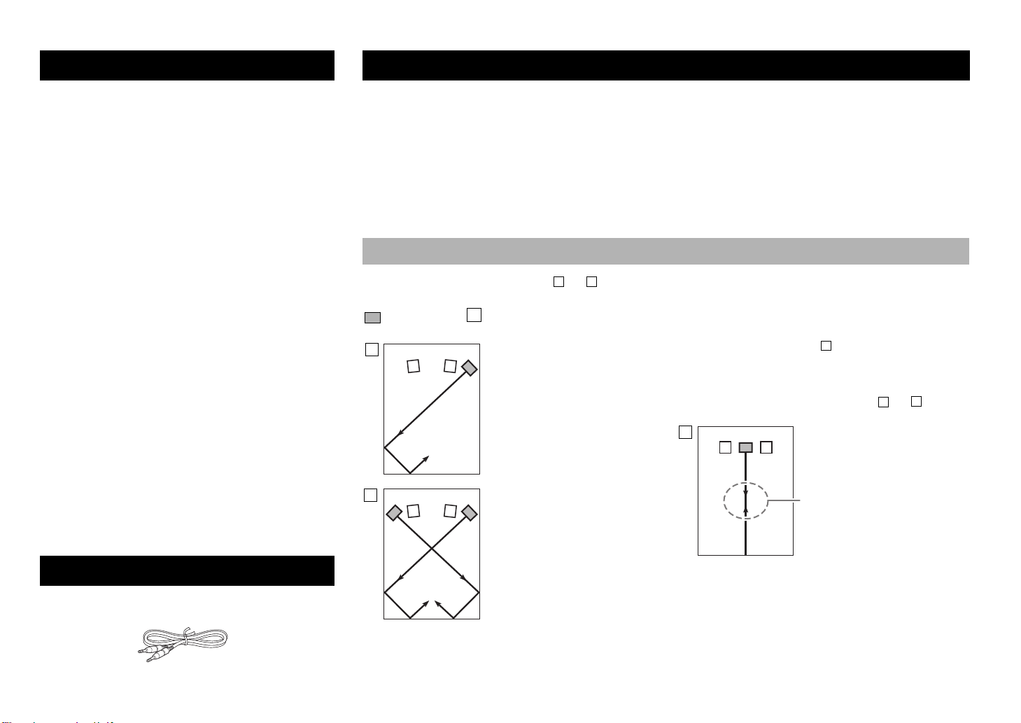
System control cable (5 m x 1)
A
B
A
B
C
A
B
C
PLACEMENT
• This subwoofer system employs Advanced Yamaha
Active Servo Technology II, which Yamaha has
developed for the production of higher quality, superbass sound. (Refer to page 7 for details on Advanced
Yamaha Active Servo Technology II.) This super-bass
sound adds a more realistic, theater-in-the-home effect to
your stereo system.
• This subwoofer can easily be added to your existing audio
system by connecting to either the speaker terminals or the
line output (pin jack) terminals of the amplifier.
• For effective use of the subwoofer, the subwoofer’s
super-bass sound should be matched to the sounds of
your front speakers. You can create the best sound
quality for various listening conditions by using the
HIGH CUT control and the PHASE switch.
• The Automatic power-switching function saves you the
trouble of pressing the power switch to turn the power on
and off.
• The subwoofer can be linked to a Yamaha component for
simultaneous power on/off operation.
Use the supplied system control cable to connect the
subwoofer to a Yamaha component that features a
system connector jack. When you turn on or off the
power to the connected component, the subwoofer will
also be turned on or off.
• You can select a bass effect suitable for the source by
using the B.A.S.S. switch.
• This subwoofer system is equipped with a linear port
unique to Yamaha that provides smooth bass response
during playback, minimizing extraneous noise not
included in the original input signal.
Since the low-end frequencies of audio signals feature long wavelengths, they are almost non-directional to human ears.
The super-bass range does not create a stereo image. Therefore, a single subwoofer may be enough to produce a highquality super-bass sound. However, using two subwoofers (similarly to L and R front speakers) can enhance your acoustic
experience.
Notes
• This unit features a magnetically shielded design. However, there is still a chance that placing it too close to a CRT-type TV set
might impair picture color. Should this happen, move this unit away from the TV set.
• If the speaker volume is very loud, furniture or window glass may resonate and the subwoofer itself may vibrate. In this case,
lower the volume level. To limit resonance, use a thick curtain or similar cloth that tends to absorb sound vibrations effectively.
Also, changing the subwoofer position may be helpful.
Subwoofer orientation
Place the subwoofer as shown in fig. or for the optimum effect.
: subwoofer : front speaker
Using one subwoofer
Place the subwoofer on the
outside of either the left or right
front speaker.
Using two subwoofers
Place them on the outside of
each front speaker.
The placement shown in fig. is also possible. However,
if the subwoofer system is placed directly facing the wall,
the bass effect may suffer due to cancellation of direct and
reflected sounds. To prevent this from happening, place the
subwoofer system at an angle, as in fig. or .
Note
There may be a case that you
cannot obtain enough super-bass
sound from the subwoofer due to
standing waves.
SUPPLIED ACCESSORY
After unpacking, check that the following accessory is
contained.
1 En
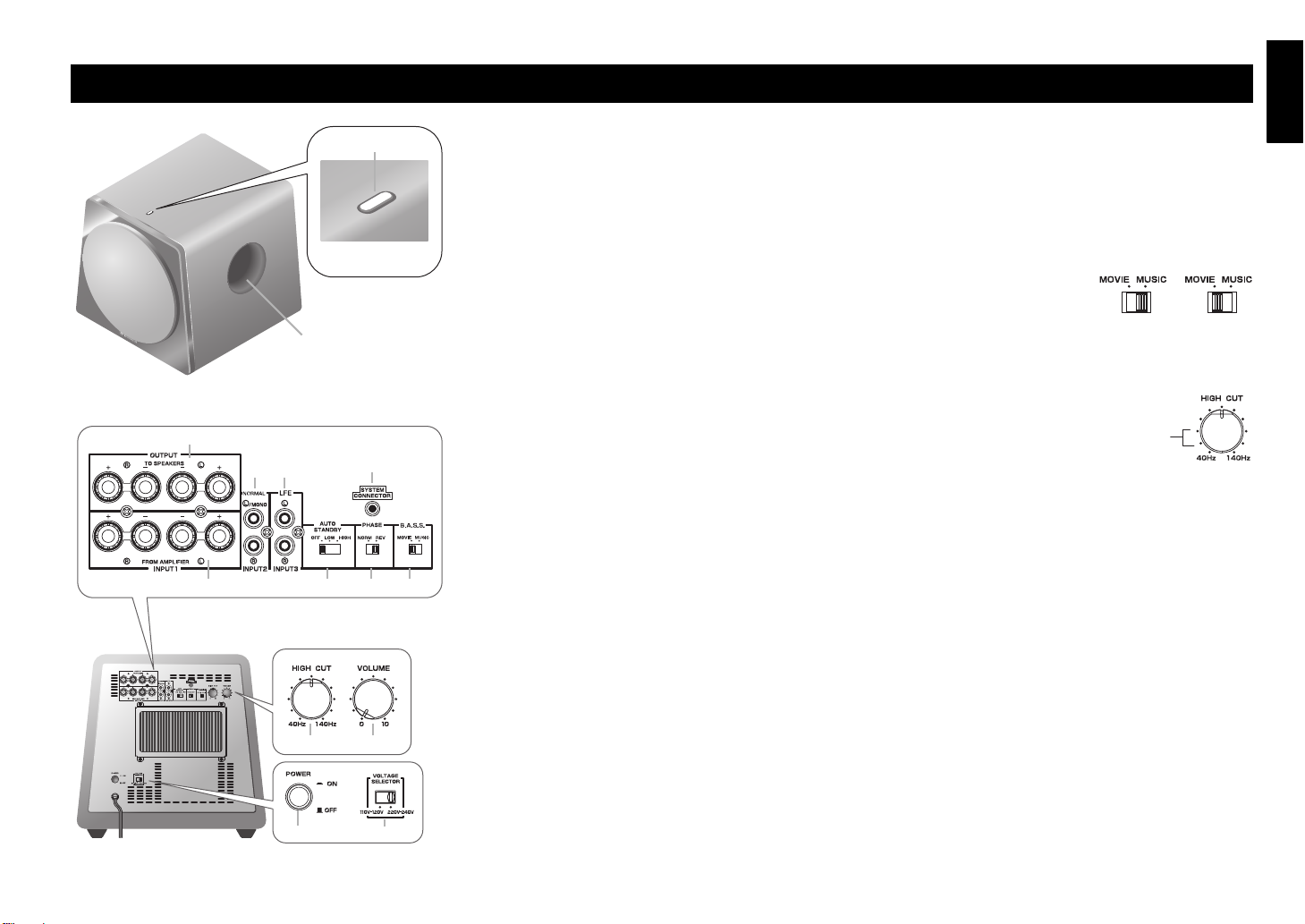
CONTROLS AND THEIR FUNCTIONS
Front
panel
Rear panel
Top panel
#
@!
45
3
6
)
798
1
2
$
* One graduation
of this control
represents 10 Hz.
English
1 Indicator
Green:
Red:
The subwoofer is turned on.
The Automatic power-switching function
has activated, and the subwoofer is in
standby mode.
Off:
The subwoofer is turned off.
2 Port
Outputs super-bass sound.
3 OUTPUT (TO SPEAKERS) terminals ( page 3)
Can be used for connecting to the main speakers.
Signals from the INPUT1 terminals are sent to these
terminals.
4 INPUT2 (NORMAL) terminals ( page 3)
Used to input line level signals from the amplifier.
5 INPUT3 (LFE) terminals ( page 3)
The HIGH CUT control ! has no effect on the signals
input to these terminals.
6 SYSTEM CONNECTOR jack ( page 5)
Connect the supplied system control cable here. If you
use the system control cable to connect a subwoofer to
a Yamaha component (that features a system connector
jack), turning on or off the power to the connected
component automatically turns the subwoofer on or off.
7
INPUT1 (FROM AMPLIFIER)
terminals ( page 4)
Used to connect the subwoofer with the speaker
terminals of the amplifier.
8 AUTO STANDBY (HIGH/LOW/OFF) switch
( page 5)
This switch is originally set to the OFF position. By
setting this switch to the HIGH or LOW position, the
subwoofer’s automatic power-switching function
operates. If you do not need this function, leave this
switch in the OFF position.
Note
Be sure to set the POWER switch to OFF before you set
the AUTO STANDBY switch.
9 PHASE switch ( page 6)
This switch is to be set to the REV (reverse) position.
However, depending on your speaker system or listening
conditions, there may be a case when better sound quality
is obtained by setting this switch to the NORM (normal)
position. Select the best position by ear.
) B.A.S.S. (Bass Action Selector System) switch
( page 6)
When this switch is set to
MUSIC, the bass sound in
audio software is well
reproduced. When the switch is set to MOVIE, the bass
sound in video software is well reproduced.
! HIGH CUT control ( page 6)
Adjusts the high
frequency cut off point.
Frequencies higher than
the frequency selected by
this control are all cut off (and not output).
@ VOLUME control
Adjusts the volume level. Turn the control clockwise to
increase the volume, and counterclockwise to decrease
the volume.
# POWER switch
During normal usage, set this switch to ON. If you plan
not to use the subwoofer for a long period of time, set
the switch to OFF.
$ VOLTAGE SELECTOR switch
(Asia and General models only)
If the preset setting of the switch is incorrect, set the
switch to the proper voltage (110-120 V/220-240 V) of
your area.
Consult your dealer if you are unsure of the correct
setting.
WARNING
Be sure to unplug the subwoofer before setting the
VOLTAGE SELECTOR switch correctly.
2 En
CONNECTIONS
1
2
1
Subwoofer
To AC outlet
Amplifier or
receiver
1 Mono pin cable
2 Audio pin cable
Amplifier or
receiver
To AC outlet To AC outlet
Subwoofer
1 Mono pin cable
Subwoofer
1 Mono pin cable
Choose one of the following connection methods most suitable for your audio system.
Choose this method if your amplifier has line output (pin jack) terminal(s).
( this page)
Choose this method if your amplifier has no line output (pin jack)
terminals. ( page 4)
Notes
• Unplug the subwoofer and other audio/video components before making connections, and do
not plug them in until all connections are completed.
• Connecting methods and terminal names on your component (such as an amplifier or receiver)
may be different from those used in this book. Please refer to the owner’s manual that came
with your component.
• All connections must be correct, that is to say L (left) to L; R (right) to R; “+” to “+” and “–” to “–”.
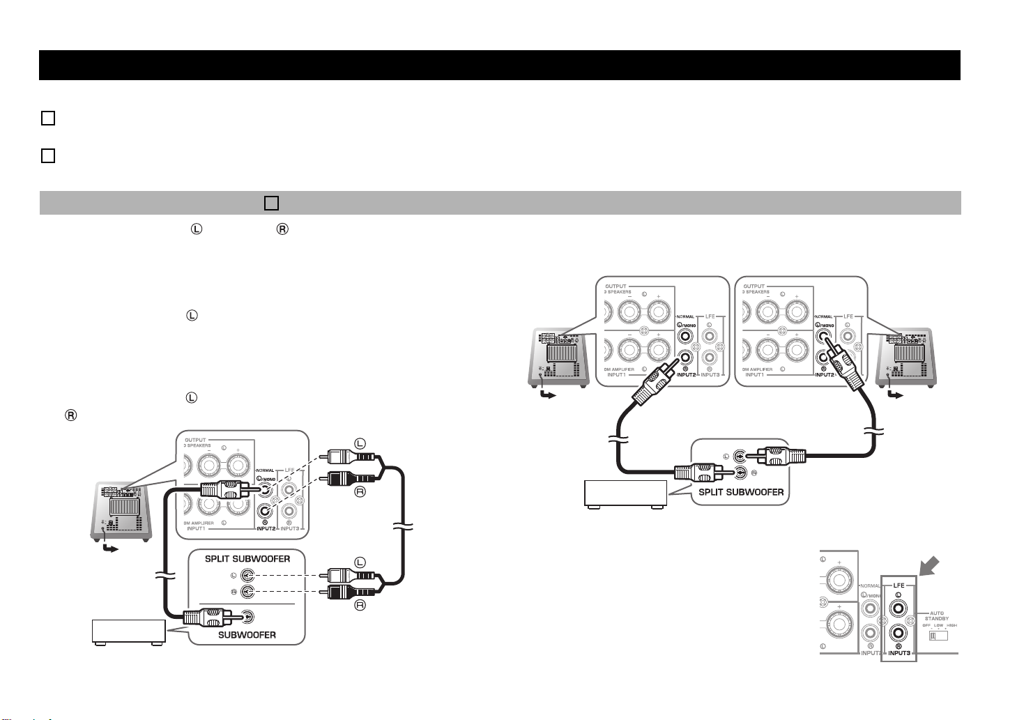
Connecting to line output (pin jack) terminal(s) of the amplifier
Audio signals input from the /MONO and INPUT 2 terminals on the subwoofer will not be output from the OUTPUT (TO SPEAKERS) terminals.
Example: Connecting one subwoofer
Use a commercially-available Mono pin cable 1 or a commercially-available Audio
pin cable 2 to make the connections.
• Connect the SUBWOOFER (or LOW PASS, etc.) terminal on the rear of the amplifier
(or AV receiver) to the /MONO INPUT2 terminal of the subwoofer using a
commercially-available Mono pin cable 1.
Alternatively,
•
When connecting the subwoofer to the SPLIT SUBWOOFER terminals (
R channels) on the rear panel of the amplifier, use a commercially-available Audio pin
cable 2 to connect the
/MONO INPUT2 terminal to the “L” side, and the
INPUT2 terminal to the “R” side of the SPLIT SUBWOOFER terminals.
featuring L and
Example: Connecting two subwoofers
3 En
Connecting to the INPUT3 (LFE) terminal(s)
If your amplifier can cut off high frequencies from
signals sent to the subwoofer, connect the amplifier to
the subwoofer’s INPUT3 (LFE) terminal(s).This will
promote higher sound quality because the signal routing
in the subwoofer is shortened by passing the built-in
HIGH CUT circuit.

Connecting to speaker output terminals of the amplifier
2
Right front
speaker
Subwoofer
To AC outlet
Left front
speaker
Speaker output
terminals
Amplifier or
receiver
Right front
speaker
To AC outlet
To AC outlet
Subwoofer
Subwoofer
Left front
speaker
Speaker output
terminals
Amplifier or
receiver
10 mm
(3/8")
Good No Good
Red:
positive (+)
Black:
negative (
–)
2
1
■ Example: Connecting the subwoofer to an amplifier that
features one set of speaker output terminals
Use speaker cables to connect the speaker output terminals of the amplifier to the
subwoofer’s INPUT 1 (FROM AMPLIFIER) terminals. Connect the front speakers to the
subwoofer’s OUTPUT (TO SPEAKERS) terminals. Although the subwoofer is connected
between the front speakers and the amplifier, the sound volume or quality will not be
affected.
Connecting one subwoofer
Connecting two subwoofers
■ Example: Connecting the subwoofer to an amplifier featuring two
sets of speaker output terminals (A and B) that can output sound
signals simultaneously
Set the amplifier so that both sets of speaker output terminals (A and B) will output
sound signals simultaneously. Then, connect the front speakers to terminals A, and
connect the subwoofer to terminals B.
Note
If your amplifier features two sets of speaker output terminals that do NOT output sound
signals simultaneously, please refer to the example for connecting an amplifier that has
only one set of speaker output terminals (see the figure on the left).
Connecting to the INPUT1/OUTPUT terminals of the subwoofer
■
Before connecting
Remove 10 mm (3/8") of insulation from the ends of the
speaker cables.
■ How to connect
1. Loosen the terminal’s knob, as shown in the figure.
2. Insert the bare wire.
3. Tighten the knob.
4. Test the firmness of the connection by pulling lightly
on the cable at the terminal.
■ Connecting the banana plug
1. Tighten the terminal knob.
2. Simply insert the banana plug into the terminal.
1
English
2
3
Notes
• Make sure that the “+” and “–” polarity markings of the speaker cables are observed and set
correctly. If these cables are reversed, the sound will be unnatural and lack bass.
• Do not let the bare speaker wires touch each other, because this could damage the subwoofer
or the amplifier.
• If the connections are faulty, no sound will be heard from the subwoofer or the speakers. Do
not insert the insulation into the hole. Sound may not be produced.
• To avoid accidents resulting from tripping over loose speaker cables, fix them to the floor.
4 En
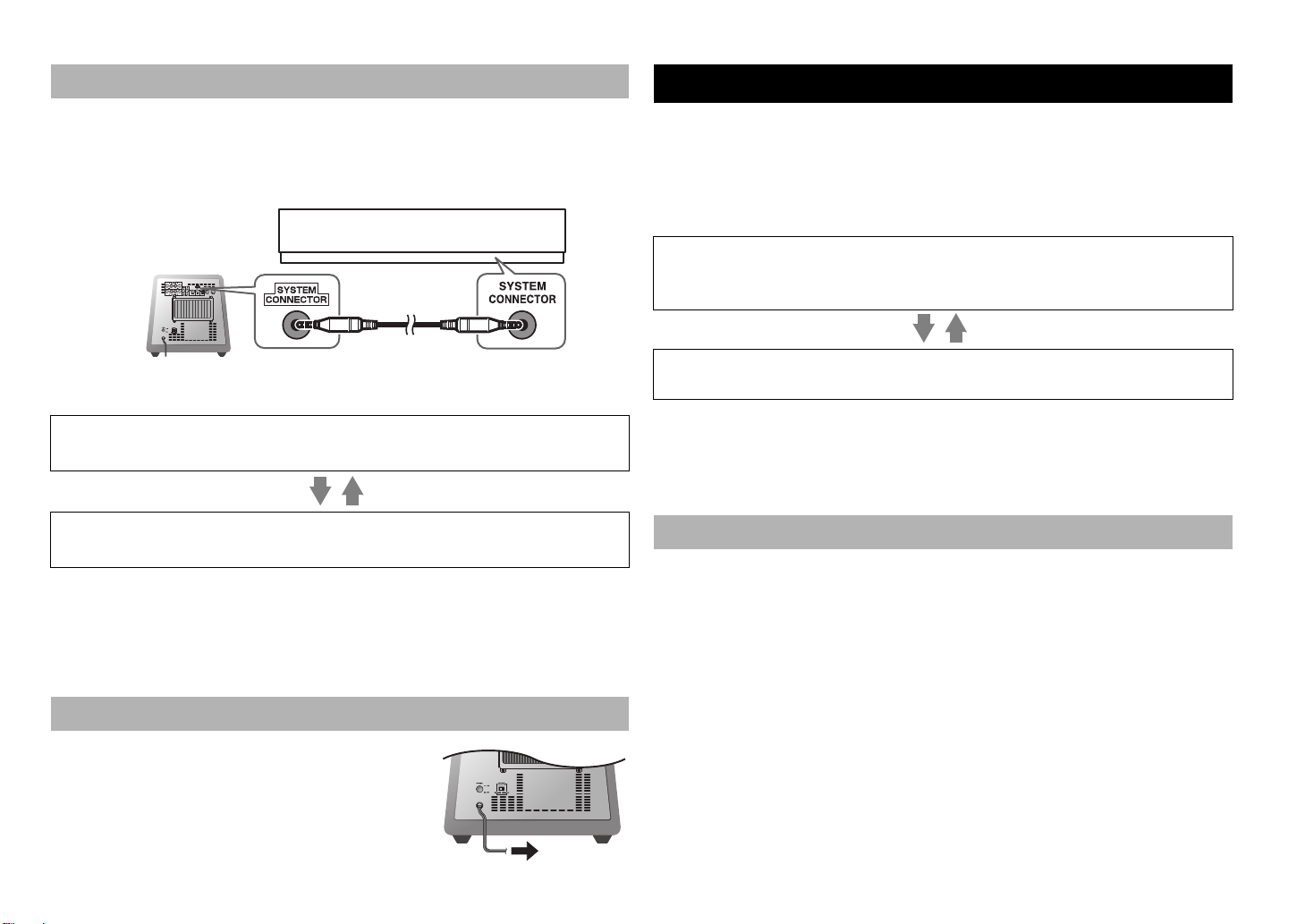
SYSTEM CONNECTIONS
Subwoofer
Supplied system
control cable
Yamaha Digital Sound Projector
To AC outlet
AUTOMATIC POWER-SWITCHING FUNCTION
If you use the supplied system control cable to connect a subwoofer to a Yamaha component
(e.g., Yamaha Digital Sound Projector that features a system connector jack), turning on or off
the power to the connected component automatically turns the subwoofer on or off.
■ Connection example
How the System Connection works
Turning on the power to the connected component will automatically turn on the subwoofer.
* The indicator lights green.
Turning off the power to the connected component will automatically turn off the subwoofer.
* The indicator turns off.
Notes
• For this feature to be available, the POWER switch on the subwoofer must be set to ON.
• Powering on/off via the system connection takes priority over the Automatic power-switching
function. (While the unit is turned on, the Automatic power-switching function is enabled.)
• To modify the settings of the connected components, please refer to the owner’s manual that
came with the respective component.
Plugging the subwoofer into an AC outlet
After all connections are completed, plug the subwoofer
and other audio/video components into AC outlets.
This function automatically places the subwoofer in standby mode if the subwoofer does
not detect a signal from the amplifier for a certain period of time. The subwoofer
automatically turns on as soon as it detects a signal from the amplifier.
The Automatic power-switching function works as follows when the AUTO STANDBY
(HIGH/LOW/OFF) switch is set to LOW or HIGH. (Normally, set the switch to LOW.)
How the Automatic power-switching function works
The subwoofer automatically enters standby mode if it does not receive an input signal
(*1) from the amplifier for 7 or 8 minutes (*2).
* The indicator color changes from green to red.
When the subwoofer detects an input signal (*1) from the amplifier, the subwoofer
automatically turns on. * The indicator color changes from red to green.
*1
When the Automatic power-switching function is enabled, the subwoofer will detect a bass signal input of
below 200Hz (such as sound effects of explosion in action movies, bass guitar or bass drum sound, etc.).
*2
This value may vary depending on the system environment. For example, it may be affected by noise
generated from other equipment.
Note
The Automatic power-switching function is available only when the POWER switch is set to ON.
Setting the AUTO STANDBY switch
Note
Be sure to set the POWER switch to OFF before you set the AUTO STANDBY switch.
LOW: The Automatic power-switching function activates at a certain level of input signal.
To enable the function, select this position.
HIGH:If the Automatic power-switching function does not work well when the AUTO
STANDBY switch is set to LOW, select this position. If the function still does not
work, slightly raise the LFE LEVEL on the amplifier.
The Automatic power-switchingy function may unexpectedly activate due to the
OFF:
system environment, for example, if the subwoofer detects noise generated from the
peripheral components. In this case, select this position to disable the Automatic powerswitching function, and manually turn the unit on or off by using the POWER switch.
Notes
• The subwoofer uses a small amount of power in auto-standby mode.
• If you plan not to use the subwoofer for a long period of time, set the POWER switch on the
rear panel to OFF, or unplug the power cable from the AC outlet.
5 En
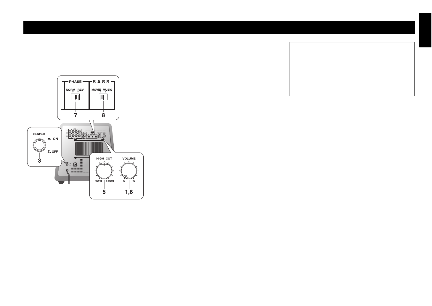
ADJUSTING THE BALANCE
Rear panel
English
To achieve natural sound with an effective super-bass
component, you must adjust the volume and tone balance
between the subwoofer and the front speakers. Follow the
procedure described below.
1. Set the VOLUME control to minimum (0).
2. Turn on the power to the component(s) connected to
the subwoofer.
If the component is connected to the subwoofer’s
SYSTEM CONNECTOR jack, turn on the power to
that component.
3. Set the POWER switch on the subwoofer to ON.
* The indicator lights green.
4. Play a source that contains low-frequency components
and adjust the output level of the front speakers using
the amplifier’s volume control to the desired listening
level. (Set all tone controls to flat.)
5. Adjust the HIGH CUT control to the position where the
desired response can be obtained.
Normally, set the control to a level a little higher than
the front speaker’s rated minimum reproducible
frequency*.
* The front speaker’s rated minimum reproducible frequency can
be looked up in the speakers’ catalog or owner’s manual.
* The HIGH CUT control has no effect on signals input to the
INPUT 3 LFE terminals.
6. Increase the volume gradually to adjust the volume
balance between the subwoofer and the front speakers.
Normally, set the control to a level where you can
obtain a little more bass effect than when the subwoofer
is not used.
7. Set the PHASE switch to the position which yields the
more natural (or preferable) phasing.
8. Set the B.A.S.S. switch to “MOVIE” or “MUSIC”
according to the played source.
MOVIE:
When a movie type source is played, the low-frequency
effects are enhanced to allow listeners to enjoy a more
powerful sound. (The sound will be richer and deeper.)
MUSIC:
When an ordinary music source is played, the excessive
low-frequency components are cut off to make the
sound clearer. (The sound will carry less bass and
reproduce the melody line more clearly.)
Note
Once the volume balance between the subwoofer and the front
speakers is adjusted, you can adjust the volume of your entire
sound system by using the amplifier’s volume control.
However, if you replace the front speakers, you will need to
make this adjustment again.
PHASE switch
In most situations, set this switch to select the
reverse mode. However, depending on your speaker
systems or listening condition, there may be a case
when better sound quality is obtained by selecting
the normal mode. Select the better mode by
monitoring the sound.
6 En
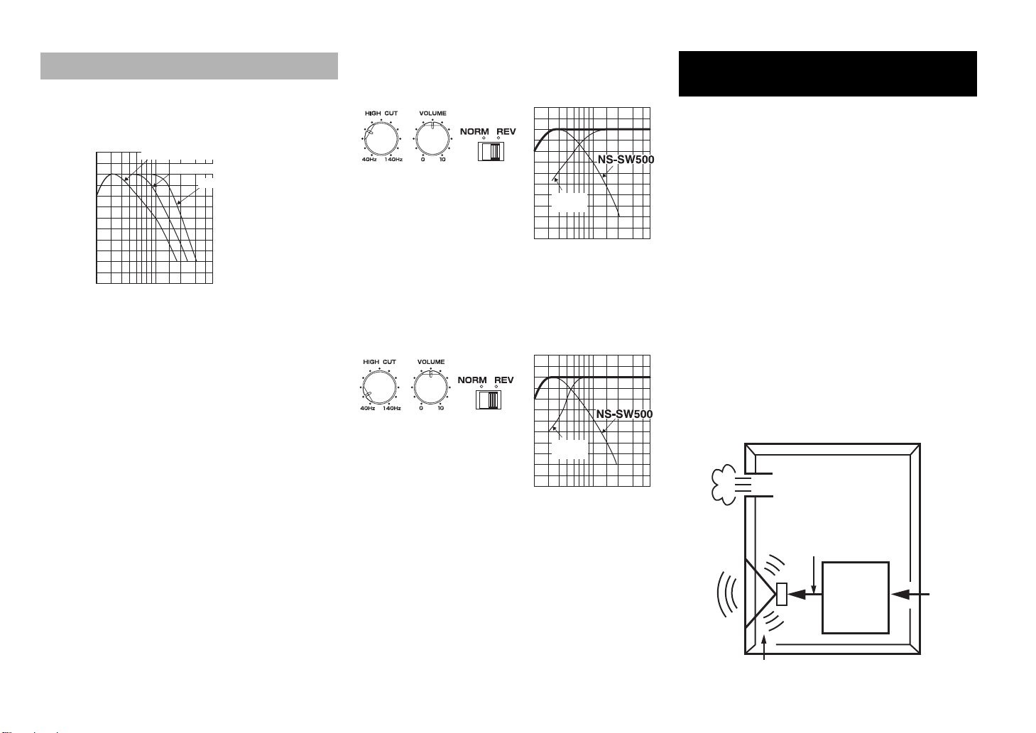
Subwoofer frequency characteristics
20 50 100 200 500Hz
40
50
60
70
80
90
dB
HIGH CUT 40 Hz
HIGH CUT 90 Hz
HIGH CUT 140 Hz
20 50 100 200 500Hz
40
50
60
70
80
90
dB
PHASE
Frequency response graph*
(70 Hz) (REV)
Front
speaker
Frequency response graph*
PHASE
Fron t
speaker
(50 Hz) (REV)
Highamplitude
bass sound
Por t
Cabinet
Advanced impedance
Converter
Active Servo
Processing
Amplifier
Signals of low amplitude
Air woofer
(Helmholtz resonator)
Signals
The figures below show the optimum adjustment of each
control and the frequency characteristics when the
subwoofer is combined with a typical front speaker system.
■ When combined with 10 cm (4") or 13 cm (5")
acoustic suspension, 2-way system front
speakers
■ When combined with 20 cm (8") or 25 cm (10")
acoustic suspension, 2-way system front
speakers
dB
90
80
70
60
50
40
20 50 100 200 500Hz
ADVANCED YAMAHA
ACTIVE SERVO TECHNOLOGY II
In 1988, Yamaha brought to the marketplace speaker
systems utilizing YST (Yamaha Active Servo Technology)
to give powerful, high quality bass reproduction. This
technique uses a direct connection between the amplifier
and speaker, allowing accurate signal transmission and
precise speaker control.
As this technology uses speaker units controlled by the
negative impedance drive of the amplifier and resonance
generated between the speaker cabinet volume and port, it
creates more resonant energy (the “air woofer” concept)
than the standard bass reflex method. This allows for bass
reproduction from much smaller cabinets than was
previously possible.
Yamaha’s newly developed Advanced YST II adds many
refinements to Yamaha Active Servo Technology,
allowing better control of the forces driving the amplifier
and speaker. From the amplifier’s point of view, the
speaker impedance changes depending on the sound
frequency. Yamaha developed a new circuit design
combining negative-impedance and constant-current
drives, which provides a more stable performance and clear
bass reproduction, without any murkiness.
7 En
* This diagram does not depict actual frequency response
characteristics.
 Loading...