

Yamaha NS-PSW700, DVR-700, NS-P700 Service Manual
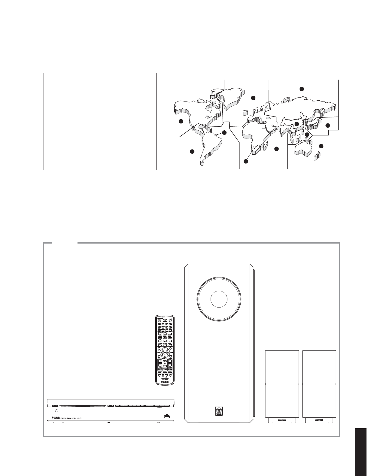
* The DVX-700 consists of the DVR-700, NS-PSW700 and NS-P700.
When accepting a repair order from the user, it is recommended to receive DVR-700, NS-PSW700 and NS-P700
as a set for the repair work.
* When DVD MODULE P.C.B. of the DVR-700 is replaced, the serial number and new device key (ID number)
MUST be reported to YCJ (Yamaha Corporation Japan) by email.
Email: ycav-keycontrol@gmx.yamaha.com
For more information, refer to “SERVICE PRECAUTIONS”.
DVR-700/
NS-PSW700/NS-P700
101120
SERVICE MANUAL
IMPORTANT NOTICE
This manual has been provided for the use of authorized YAMAHA Retailers and their service personnel.
It has been assumed that basic service procedures inherent to the industry, and more specifi cally YAMAHA Products, are already known
and understood by the users, and have therefore not been restated.
WARNING:
Failure to follow appropriate service and safety procedures when servicing this product may result in personal injury,
destruction of expensive components, and failure of the product to perform as specifi ed. For these reasons, we advise
all YAMAHA product owners that any service required should be performed by an authorized YAMAHA Retailer or
the appointed service representative.
IMPORTANT:
The presentation or sale of this manual to any individual or fi rm does not constitute authorization, certifi cation or
recognition of any applicable technical capabilities, or establish a principle-agent relationship of any form.
The data provided is believed to be accurate and applicable to the unit(s) indicated on the cover. The research, engineering, and service
departments of YAMAHA are continually striving to improve YAMAHA products. Modifications are, therefore, inevitable and
specifi cations are subject to change without notice or obligation to retrofi t. Should any discrepancy appear to exist, please contact the
distributor's Service Division.
WARNING:
Static discharges can destroy expensive components. Discharge any static electricity your body may have
accumulated by grounding yourself to the ground buss in the unit (heavy gauge black wires connect to this buss).
IMPORTANT:
Turn the unit OFF during disassembly and part replacement. Recheck all work before you apply power to the unit.
■ CONTENTS
TO SERVICE PERSONNEL ........................................ 2–3
PREVENTION OF ELECTROSTATIC DISCHARGE ......4
REGION MANAGEMENT INFORMATION .....................5
SYSTEM COMPOSITION ................................................5
FRONT PANELS .........................................................6–8
REAR PANELS .........................................................9–10
REMOTE CONTROL PANELS ..................................... 11
SPECIFICATIONS ................................................... 12–14
INTERNAL VIEW .......................................................... 15
SERVICE PRECAUTIONS ...................................... 16–17
DVR-700 DISASSEMBLY PROCEDURES ............. 18–20
NS-PSW700 DISASSEMBLY PROCEDURES .......21–23
UPDATING FIRMWARE ..........................................24–37
SELF-DIAGNOSTIC FUNCTION ............................38–63
DISPLAY DATA .......................................................64–65
IC DATA ...................................................................66–83
PIN CONNECTION DIAGRAMS .............................84–86
BLOCK DIAGRAMS ................................................87–89
PRINTED CIRCUIT BOARDS .................................90–98
SCHEMATIC DIAGRAMS ..................................... 99–106
REPLACEMENT PARTS LIST .............................107–117
REMOTE CONTROL ............................................118–119
SYSTEM MENU ...........................................................120
animate '08.12
P.O.Box 1, Hamamatsu, Japan
Copyright © 2008 All rights reserved.
This manual is copyrighted by YAMAHA and may not be copied or
redistributed either in print or electronically without permission.
DVD CONTROLLER
DVR-700
SUBWOOFER / SYSTEM CONTROL
NS-PSW700
SPEAKERS
NS-P700
DVD HOME THEATER SYSTEM
DVX-700
本资料由OKXIA视听皮带资源库www.okxia.cn提供
2
DVR-700/NS-PSW700/NS-P700
DVR-700/
NS-PSW700/NS-P700
This product contains chemicals known to the State of California to cause cancer, or birth defects or other reproductive
harm.
DO NOT PLACE SOLDER, ELECTRICAL/ELECTRONIC OR PLASTIC COMPONENTS IN YOUR MOUTH FOR ANY REASON
WHATSOEVER!
Avoid prolonged, unprotected contact between solder and your skin! When soldering, do not inhale solder fumes or
expose eyes to solder/flux vapor!
If you come in contact with solder or components located inside the enclosure of this product, wash your hands before
handling food.
1. Critical Components Information
Components having special characteristics are marked ⚠ and
must be replaced with parts having specifications equal to those
originally installed.
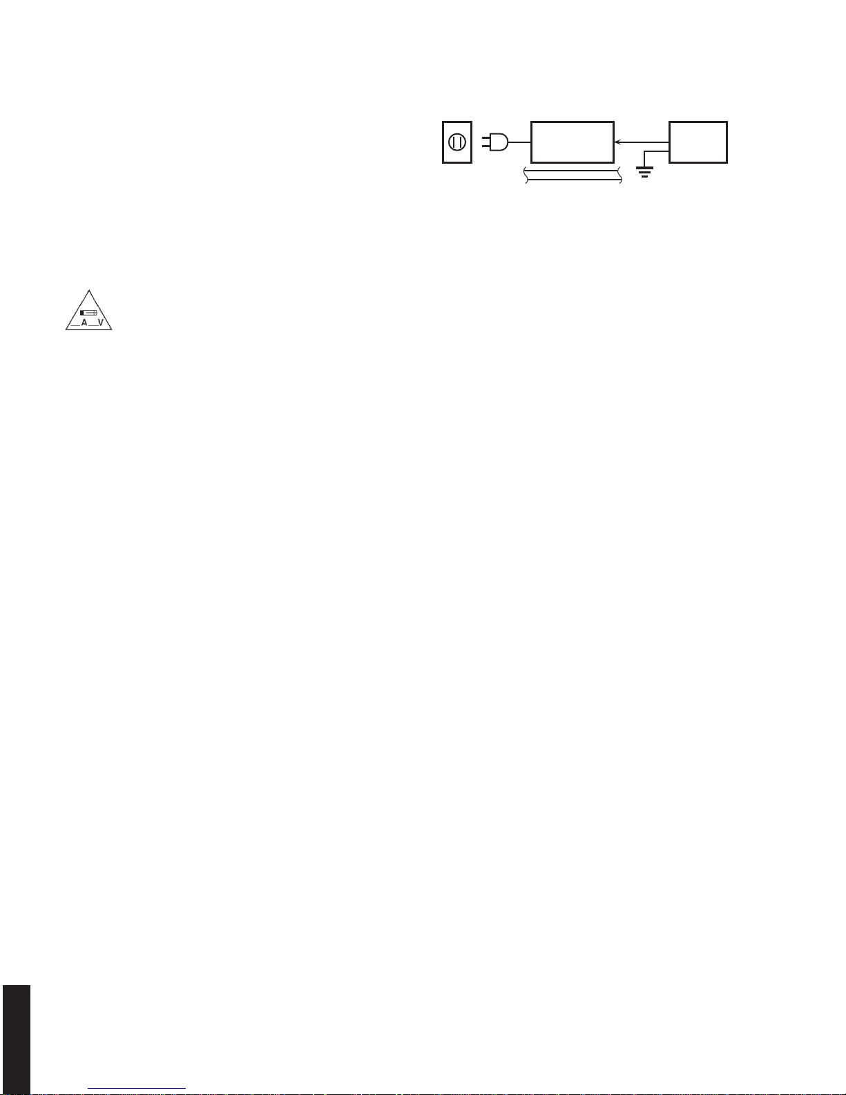
2. Leakage Current Measurement (For 120V Models Only)
When service has been completed, it is imperative to verify
that all exposed conductive surfaces are properly insulated
from supply circuits.
• Meter impedance should be equivalent to 1500 ohms shunted
by 0.15 μF.
All of the P.C.B.s installed in this unit and solder joints are soldered using the lead free solder.
Among some types of lead free solder currently available, it is recommended to use one of the following types for the
repair work.
• Sn + Ag + Cu (tin + silver + copper)
• Sn + Cu (tin + copper)
• Sn + Zn + Bi (tin + zinc + bismuth)
Caution:
As the melting point temperature of the lead free solder is about 30°C to 40°C (50°F to 70°F) higher than that of the lead
solder, be sure to use a soldering iron suitable to each solder.
■ TO SERVICE PERSONNEL
• Leakage current must not exceed 0.5mA.
• Be sure to test for leakage with the AC plug in both polarities.
WALL
OUTLET
EQUIPMENT
UNDER TEST
AC LEAKAGE
TESTER OR
EQUIVALENT
INSULATING
TABLE
WARNING: CHEMICAL CONTENT NOTICE!
About lead free solder
WARNING: Laser Safety
This product contains a laser beam component. This component may emit invisible, as well as visible radiation,
which may cause eye damage. To protect your eyes and skin from laser radiation, the following precautions must
be used during servicing of the unit.
1) When testing and/or repairing any component within the product, keep your eyes and skin more than 30 cm/1 feet
away from the laser pick-up unit at all times. Do not stare at the laser beam at any time.
2) Do not attempt to readjust, disassemble or repair the laser pick-up, unless noted elsewhere in this manual.
3) CAUTION: Use of controls, adjustments or performance of procedures other than those specified herein may result in
hazardous radiation exposure.
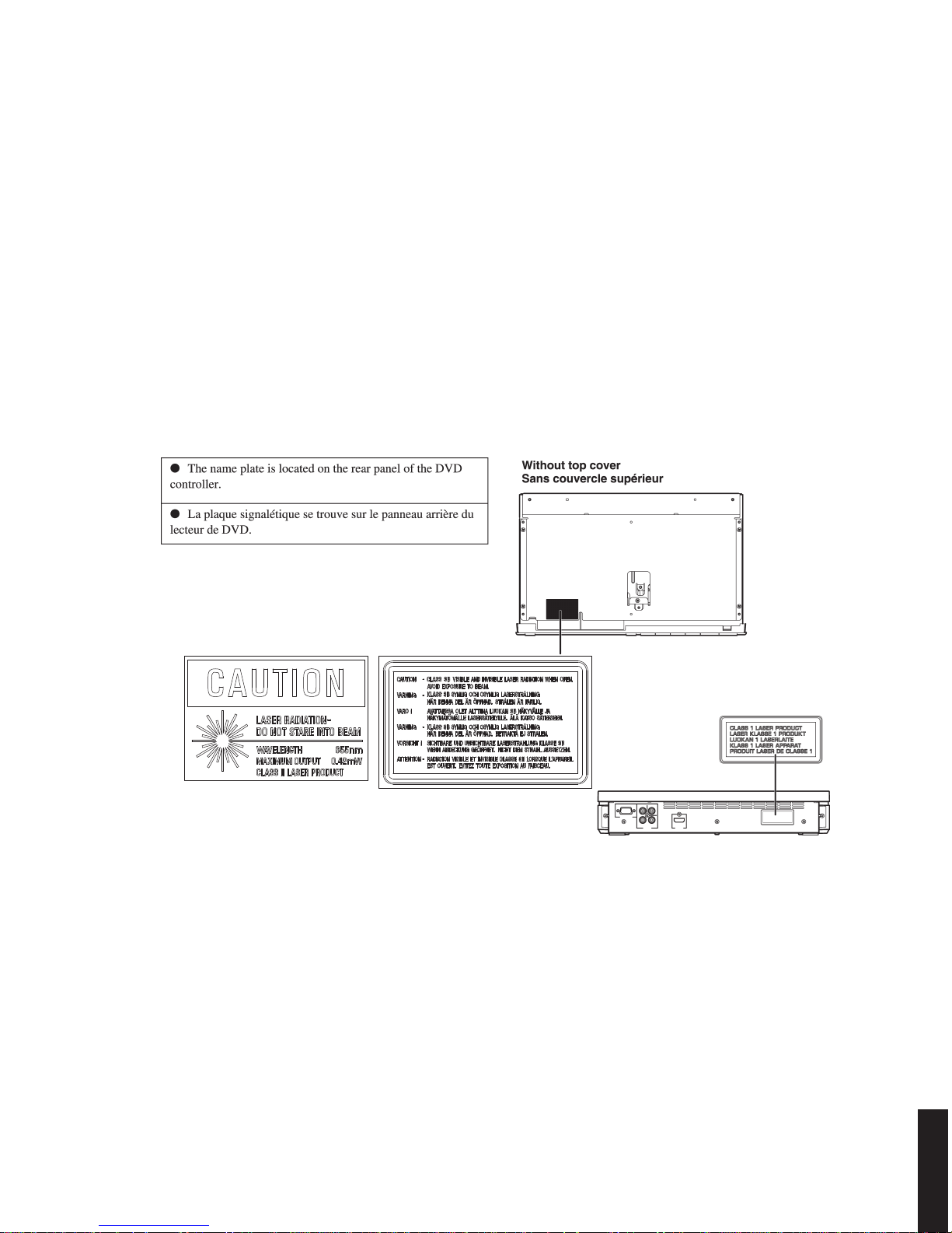
For U model
“CAUTION”
“F701: FOR CONTINUED PROTECTION AGAINST RISK OF FIRE, REPLACE ONLY WITH SAME TYPE 5A, 125V
FUSE.”
For C model
CAUTION
F701: REPLACE WITH SAME TYPE 5A, 125V FUSE.
ATTENTION
F701: UTILISER UN FUSIBLE DE RECHANGE DE MÉME TYPE DE 5A, 125V.
3
DVR-700/NS-PSW700/NS-P700
DVR-700/
NS-PSW700/NS-P700
Laser Emitting conditions:
1) When the Top Cover is removed, and the STANDBY/ON SW is turned to the “ON” position, the laser component will
emit a beam for several seconds to detect if a disc is present. During this time (5-10 sec.) the laser may radiate
through the lens of the laser pick-up unit. Do not attempt any servicing during this period!
If no disc is detected, the laser will stop emitting the beam. When a disc is loaded, you will not be exposed to any
laser emissions.
2) The laser power level can be adjusted with the VR on the pick-up PWB, however, this level has been set by the factory
prior to shipping from the factory. Do not adjust this laser level control unless instruction is provided elsewhere in this
manual. Adjustment of this control can increase the laser emission level from the device.
Type: Semiconductor laser ALGaInP
Wave length: 655 nm (DVD) / 790 nm (VCD/CD)
Output Power: 5 mW (DVD) / 7 mW (VCD/CD)
Beam divergence: 20 degrees
Laser Diode Properties
The primary side of the power supply carries live mains voltage when the player is connected to the mains even
when the player is switched off !
This primary area is not shielded so it is possible to accidentally touch copper tracks and/or components when servicing
the player.
Service personnel have to take precautions to prevent touching this area or components in this area.
Note:
The screws on the DVD mechanism may never be touched, removed or re-adjusted.
Handle the DVD mechanism with care when the unit has to be exchanged!
The DVD mechanism is very sensitive for dropping or giving shocks.
Warning for power supply
U, C models A, G, F, L, V models
4
DVR-700/NS-PSW700/NS-P700
DVR-700/
NS-PSW700/NS-P700
Some semiconductor (solid state) devices can be damaged easily by static electricity. Such components commonly are
called Electrostatically Sensitive (ES) Devices. Examples of typical ES devices are integrated circuits and some field-effect
transistors and semiconductor “chip” components. The following techniques should be used to help reduce the incidence
of component damage caused by electro static discharge (ESD).
1. Immediately before handling any semiconductor component or semiconductor-equipped assembly, drain off any ESD
on your body by touching a known earth ground. Alternatively, obtain and wear a commercially available discharging
ESD wrist strap, which should be removed for potential shock reasons prior to applying power to the unit under test.
2. After removing an electrical assembly equipped with ES devices, place the assembly on a conductive surface such as
aluminum foil, to prevent electrostatic charge buildup or exposure of the assembly.
3. Use only a grounded-tip soldering iron to solder or unsolder ES devices.
4. Use only an anti-static solder removal device. Some solder removal devices not classified as “anti-static (ESD protected)” can generate electrical charge sufficient to damage ES devices.
5. Do not use freon-propelled chemicals. These can generate electrical charges sufficient to damage ES devices.
6. Do not remove a replacement ES device from its protective package until immediately before you are ready to install it.
(Most replacement ES devices are packaged with leads electrically shorted together by conductive foam, aluminum foil
or comparable conductive material).
7. Immediately before removing the protective material from the leads of a replacement ES device, touch the protective
material to the chassis or circuit assembly into which the device will be installed.
CAUTION: Be sure no power is applied to the chassis or circuit, and observe all other safety precautions.
8. Minimize bodily motions when handling unpackaged replacement ES devices. (Otherwise harmless motion such as
brushing together of your fabric clothes or lifting of your foot from a carpeted floor can generate static electricity (ESD)
sufficient to damage an ES device).
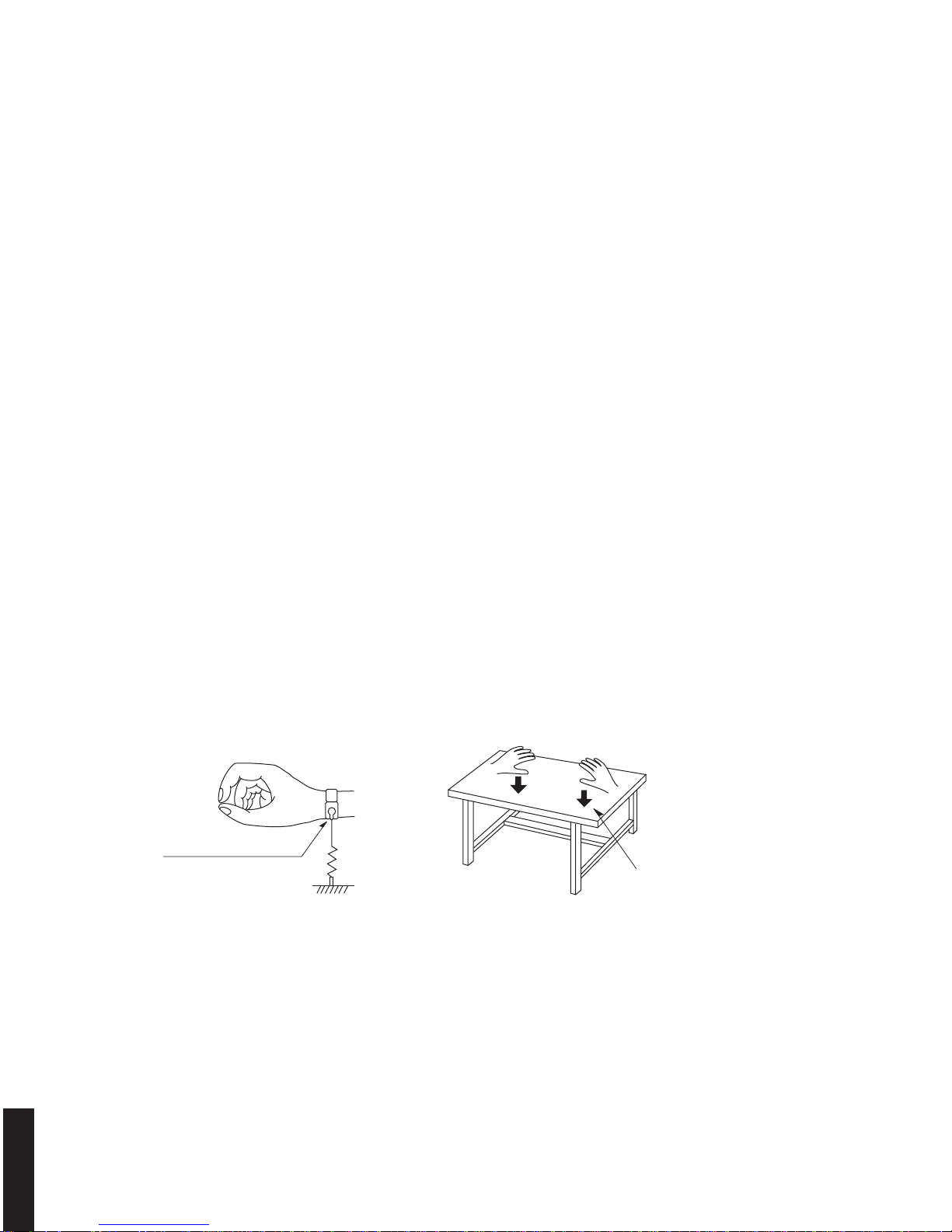
Grounding for electrostatic breakdown prevention
1. Human body grounding.
Use the antistatic wrist strap to discharge the static electricity from your body.
2. Work table grounding.
Put a conductive material (sheet) or steel sheet on the area where the optical pickup is placed and ground the sheet.
Caution:
The static electricity of your clothes will not be grounded through the wrist strap. So take care not to let your clothes touch
the optical pickup.
■ PREVENTION OF ELECTROSTATIC DISCHARGE
1M-ohms
Conductive material
(sheet) or steel sheet
Anti-static wrist strap
5
DVR-700/NS-PSW700/NS-P700
DVR-700/
NS-PSW700/NS-P700
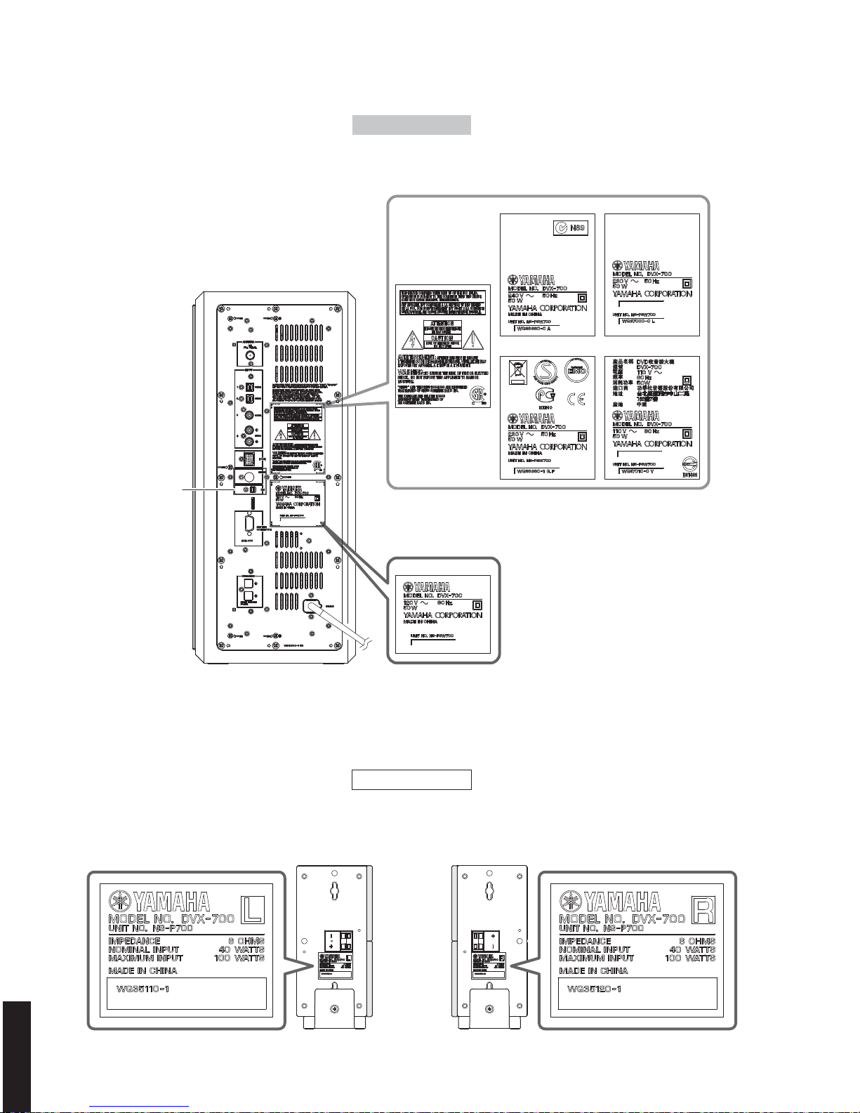
▼ DVR-700
▼ NS-P700 L / R
▼ NS-PSW700
DVX-700
This product incorporates copyright
protection technology that is protected
by method claims of certain U.S. patents
and other intellectual property rights
owned by Macrovision Corporation
and other rights owners. Use of this
copyright protection technology must be
authorized by Macrovision Corporation,
and is intended for home and other
limited viewing uses only unless
otherwise authorized by Macrovision
Corporation. Reverse engineering or
disassembly is prohibited.
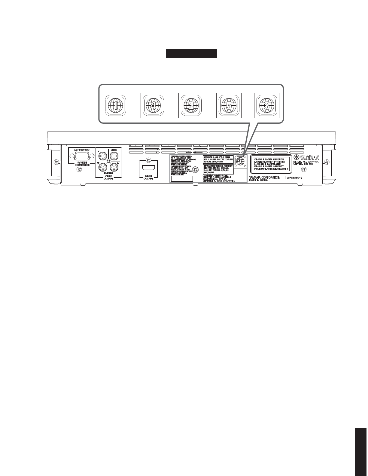
Region Management Information: This DVD player is designed and manufactured to respond to the Region
Management Information that is recorded on a DVD disc. If the Region number described on the DVD disc does
not correspond to the Region number of this DVD player, this DVD player cannot play this disc.
■ REGION MANAGEMENT INFORMATION
1
4
2
2
2
2
5
5
4
3
6
The DVX-700 consists of the DVR-700, NS-PSW700 and NS-P700.
■ SYSTEM COMPOSITION
6
DVR-700/NS-PSW700/NS-P700
DVR-700/
NS-PSW700/NS-P700
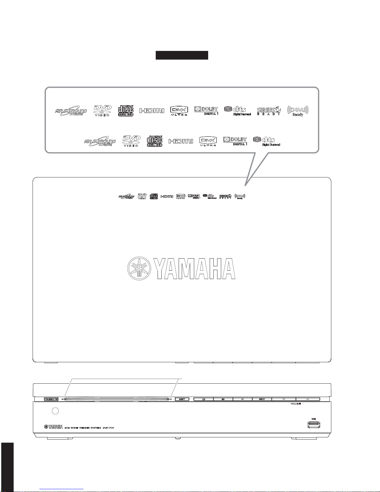
U, C, A, G, F, L, V models
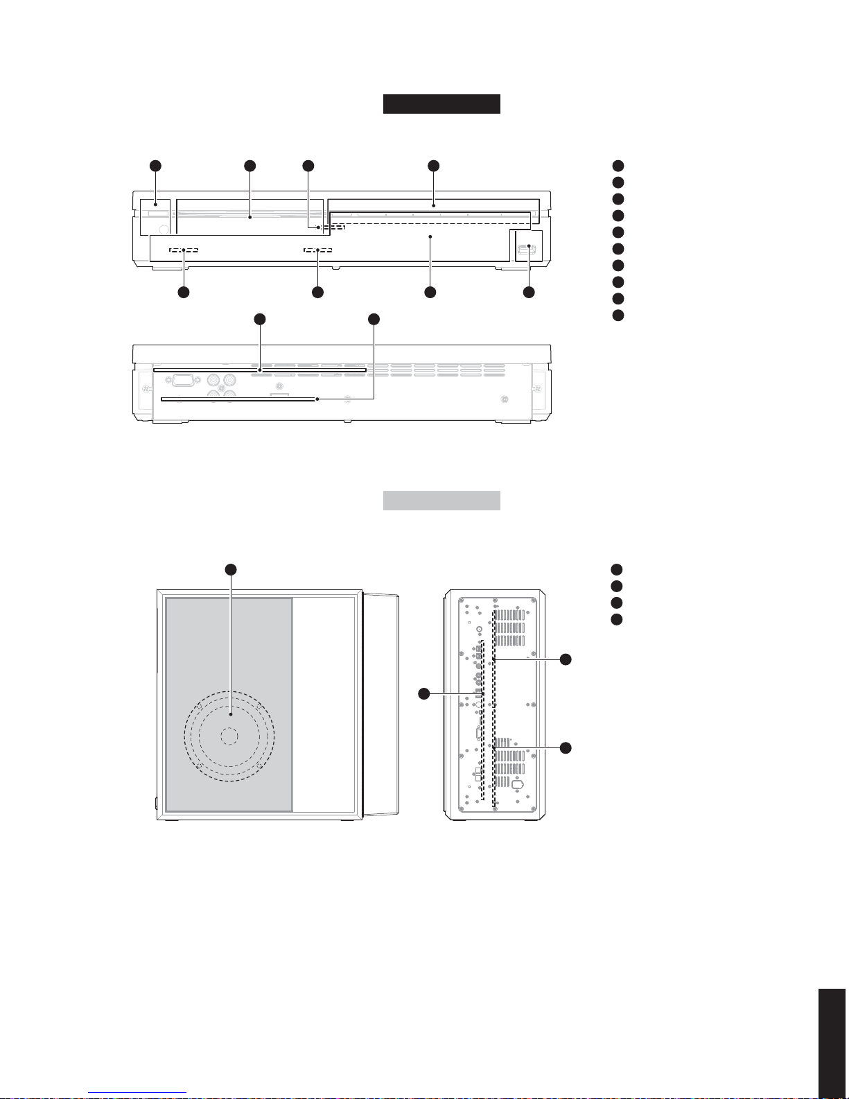
■ FRONT PANELS
DVR-700
▼ Front view
▼ Top view
(A, G, F, L, V models)
POWER indicators
(U, C model)
7
DVR-700/NS-PSW700/NS-P700
DVR-700/
NS-PSW700/NS-P700
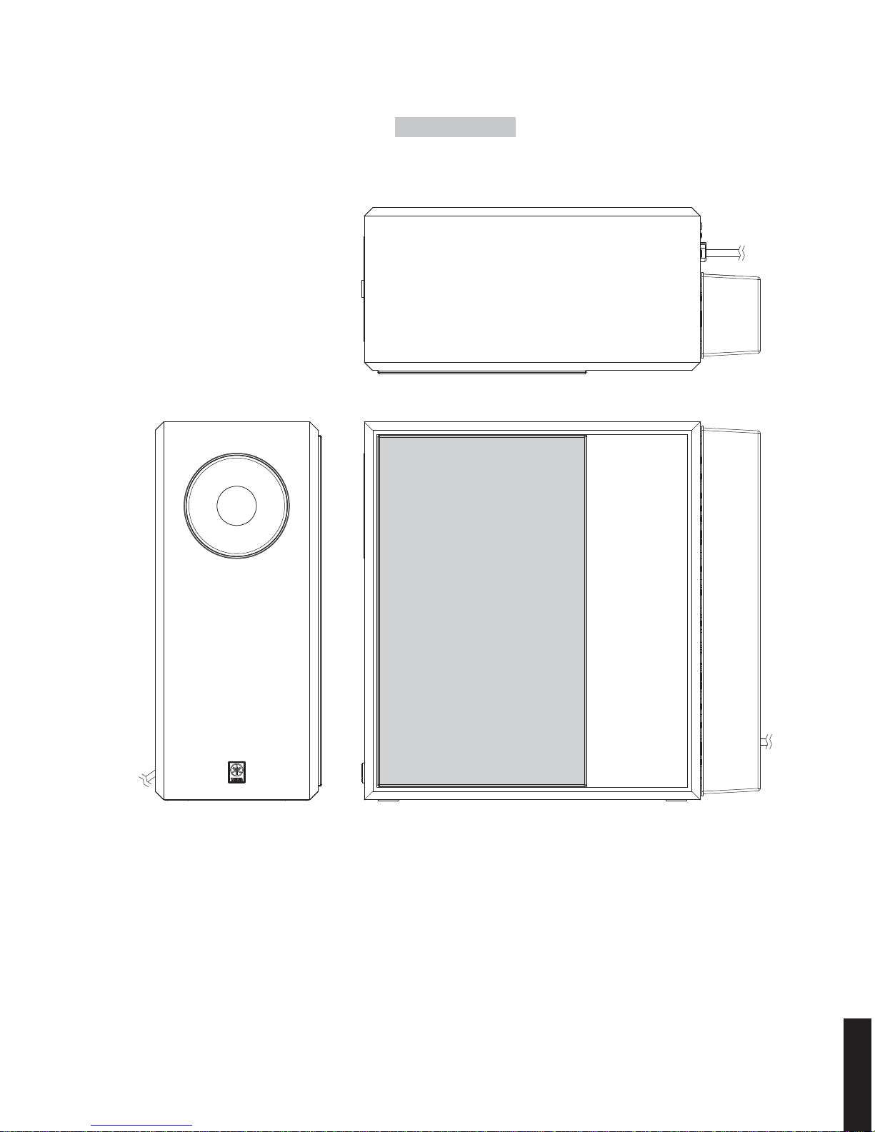
U, C, A, G, F, L, V models
NS-PSW700
▼ Front view ▼ Side view
▼ Top view
8
DVR-700/NS-PSW700/NS-P700
DVR-700/
NS-PSW700/NS-P700
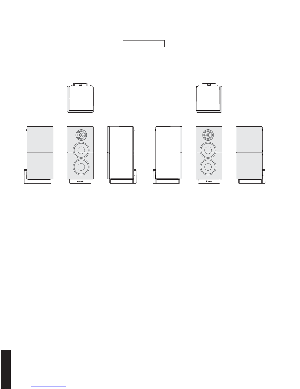
▼ Front view
▼ Side view ▼ Front view ▼ Side view▼ Side view
▼ Top view
NS-P700 R ▼ Top viewNS-P700 L
▼ Side view
NS-P700
9
DVR-700/NS-PSW700/NS-P700
DVR-700/
NS-PSW700/NS-P700
G model L, V modelsA modelU, C models F model
■ REAR PANELS
U, C, A, G, F, L, V models
DVR-700
10
DVR-700/NS-PSW700/NS-P700
DVR-700/
NS-PSW700/NS-P700
NS-P700 RNS-P700 L
U, C, A, G, F, L, V models
NS-PSW700
U, C, A, G, F, L, V models
NS-P700
U, C models
U, C models
U, C models
A model
G, F models
L model
V model
11
DVR-700/NS-PSW700/NS-P700
DVR-700/
NS-PSW700/NS-P700
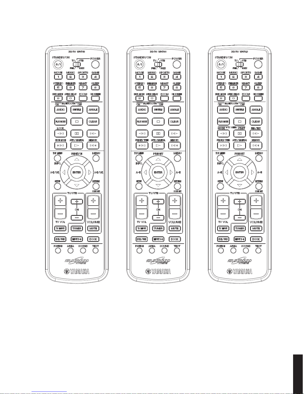
■ REMOTE CONTROL PANELS
U, C models A, L, V models G, F models

12
DVR-700/NS-PSW700/NS-P700
DVR-700/
NS-PSW700/NS-P700
■ SPECIFICATIONS
■ Speaker Section
Type ............................................Bass reflex speaker system
Magnetic shielding type
Driver
Woofer ..................................16 cm (6-5/16") cone type x 1
Frequency Response
.................................................... 35 Hz to 130 kHz (-10dB)
■ Input/Output Section
Input Terminal
Analog audio ........................... INPUT4 (AUX L/R: pin jack)
Digital audio .......................................INPUT1, 2 (OPTICAL)
INPUT3 (COAXIAL)
Others .............................DOCK (YDS-10, YDS-11, YBA-10)
FM antenna terminal
XM tuner (U, C models)
SIRIUS tuner (U, C models)
Output Terminal
Analog audio ................................................ SPEAKERS L/R
Others ...............................................SYSTEM CONNECTOR
■ General
Power Supply
U, C models ..................................................... AC 120 V, 60 Hz
A model ............................................................ AC 240 V, 50 Hz
G, F, L models .................................................. AC 230 V, 50 Hz
V model ............................................................ AC 110 V, 60 Hz
Power Consumption
......................................................................................50 W
Standby Power Consumption (reference data)
.......................................................................Less than 1 W
Dimensions (W x H x D)
Excluding legs ......................194 mm x 450 mm x 400 mm
(7-5/8" x 17-11/16" x 15-3/4")
Weight .................................................13 kg (28 lbs. 10 oz.)
Finish
Black color .................................U, C, A, G, F, L, V models
■ Speaker Section
Type ..................................................Magnetic shielding type
Driver
Woofer .................................5.5 cm (2-3/16") cone type x 2
Tweeter ......................2.5 cm (1") balanced dome type x 1
Frequency Response
.................................................... 130 Hz to 20 kHz (-10dB)
Input Power
Nominal ......................................................................... 40 W
Maximum .................................................................... 100 W
■ General
Dimensions (W x H x D)
Excluding stands
...............................................95 mm x 190 mm x 98 mm
(3-3/4" x 7-1/2" x 3-7/8")
Including stands
Upright position
...........................................95 mm x 206 mm x 106 mm
(3-3/4" x 8-1/8" x 4-3/16")
Horizontal position
.........................................190 mm x 111 mm x 106 mm
(7-1/2" x 4-3/8" x 4-3/16")
Weight (Excluding stands)
.............................................................1.2 kg (2 lbs. 10 oz.)
Finish
Black color .................................U, C, A, G, F, L, V models
DVR-700
NS-PSW700
NS-P700
■ Input/Output Section
Input Terminal
Others .............................................................................USB
Output Terminal
Video .......................................................VIDEO (composite)
COMPONENT (Y, P
B
, PR)
HDMI
Others ...............................................SYSTEM CONNECTOR
■ General
Dimensions (W x H x D)
.............................................360 mm x 68 mm x 224 mm
(14-3/16" x 2-11/16" x 8-13/16")
Weight ..................................................2.6 kg (5 lbs. 11 oz.)
Finish
Black color .................................U, C, A, G, F, L, V models
■ Amplifier Section
Maximum Power (JEITA, 6 ohms, 10 % THD)
SP OUT (1 kHz) ........................................................... 70 W
SUBWOOFER (100 Hz) ................................................ 70 W
Minimum RMS Output Power (6 ohms, 1 % THD)
SP OUT (1 kHz) ........................................................... 55 W
SUBWOOFER (100 Hz) ................................................ 55 W
Input Sensitivity/Input Impedance
AUX ......................................................... 350 mV/32 k-ohms
Maximum Input Signal Level (1 kHz, DSP=Thru)
AUX .................................................................2.2 V or more
Frequency Response (Analog, Digital input)
SP OUT .................................................. -2.0 ±1 dB (20 Hz)
0 dB (1 kHz)
-0.5 ±1 dB (20 kHz)
Signal to Noise Ratio (IHF-A network)
SP OUT
Analog .........................................................82 dB or more
Digital ..........................................................98 dB or more
Total Harmonic Distortion
(Analog, Digital 20 kHz-LPF, 1 kHz, 18.5 V/6 ohms)
SP OUT ..........................................................0.06 % or less
Residual Noise
(Analog, Digital 20 kHz-LPF, 1 kHz, 18.5 V/6 ohms)
SP OUT ......................................................................138 μV
13
DVR-700/NS-PSW700/NS-P700
DVR-700/
NS-PSW700/NS-P700
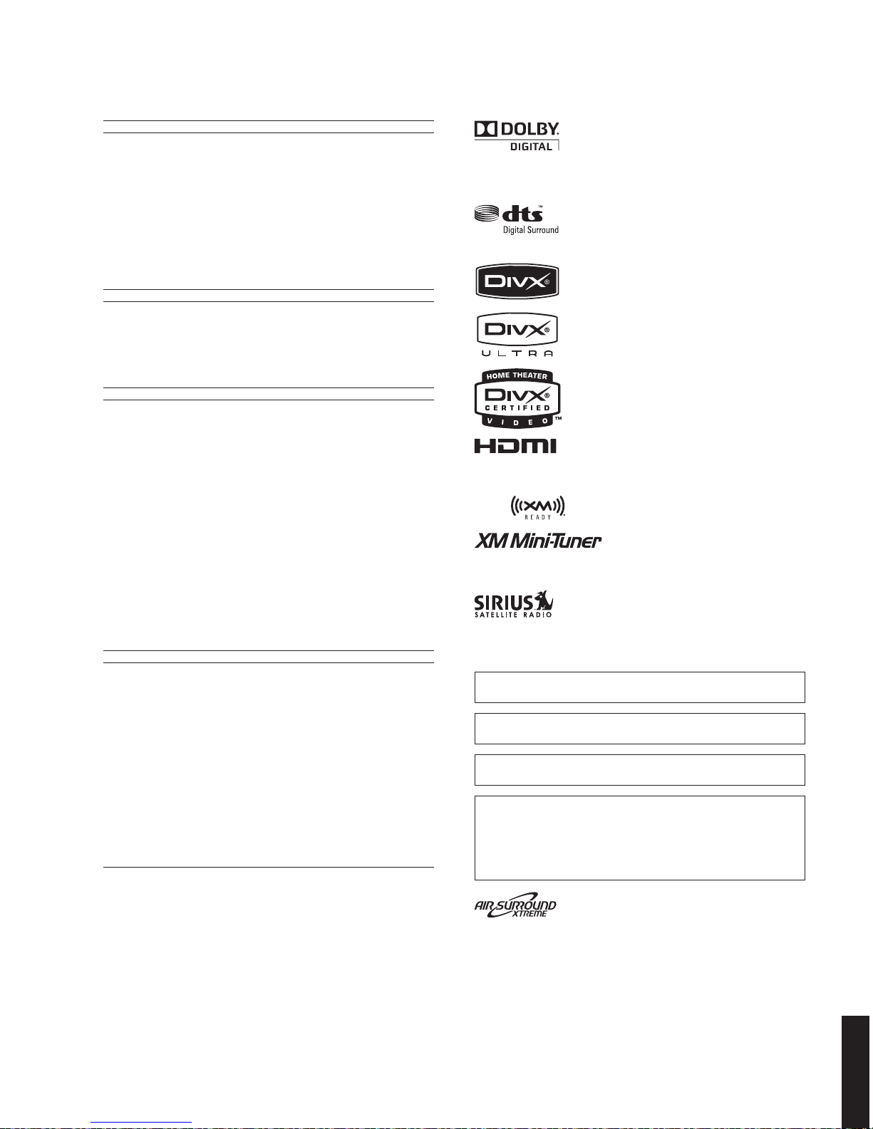
Manufactured under license from Dolby Laboratories. “Dolby”, “Pro
Logic”, “MLP Lossless” and the double-D symbol are trademarks of Dolby
Laboratories.
“DTS” and “DTS Digital Surround” are registered trademarks of DTS, Inc.
HDMI, the HDMI logo and High Definition Multimedia Interface are
trademarks or registered trademarks of HDMI Licensing LLC.
The XM name and related logos are registered trademarks of XM Satellite
Radio Inc.
©2006 SIRIUS Satellite Radio Inc. “SIRIUS”, “SiriusConnect”, the SIRIUS
dog logo, channel names and logos are trademarks of SIRIUS Satellite
Radio Inc.
This system employs new technologies and algorithms that make it
possible to achieve 7-channel surround sound with only two speakers,
and without using wall reflections.
DivX
®
, DivX® Ultra Certified, and associated logos
are trademarks of DivX
®
, Inc. and are used under
license.
U .......................U.S.A. model
C .................Canadian model
A ................ Australian model
G .................European model
F .................... Russian model
L .................Singapore model
V ..................... Taiwan model
■ DVD Section
Video Output
Composite .................................................1 Vp-p (75 ohms)
Y Output/Component Video Output
Component ...............................................1 Vp-p (75 ohms)
Pb Output/Component Video Output
Component ............................................0.7 Vp-p (75 ohms)
Pr Output/Component Video Output
Component ............................................0.7 Vp-p (75 ohms)
■ Tuner Section
FM Tuning Range
U, C models ....................................... 87.50 to 107.90 MHz
A, G, F, L, V models .......................... 87.50 to 108.00 MHz
* G, F models: RDS function 75 ohms unbalanced
■ Other Section
Sound Field (MOVIE, MUSIC, SPORTS, GAME)
......................................................................Surround mode
Night listening mode
Extended stereo
Compressed music enhancer
Virtual Surround Processor
.....................................................AIR SURROUND XTREME
Audio Decode
..........................................................................Dolby Digital
Dolby Pro Logic II
DTS
MPEG2
Speakers Distance Mode
........................................................Wide / Normal / Narrow
■ General
Accessories
Remote control ................................................................ x 1
Battery (R6, AA, UM-3) ................................................... x 2
Indoor FM antenna (1.4 m) ............................................. x 1
Speaker cable ass’y (4 m) .............................................. x 2
System cable (4 m) ......................................................... x 1
Video pin cable (1.5 m) .................................................. x 1
Cover (for NS-PSW700) ................................................... x 1
Screw (for cover / 3x6) ................................................. x 6
Stand (for NS-P700) ........................................................ x 2
Nonskid pad (for stand) ............................................. x 18
Screw (for stand / 4x10) ............................................... x 2
* Specifications are subject to change without notice due to product
improvements.
“Apple”, “iPod”, and “iTunes” are trademarks of Apple Inc., registered
in the U.S. and other countries.
Bluetooth is a registered trademark of Bluetooth SIG and is used by
Yamaha in accordance with a license agreement.
Windows Media is either a registered trademark or trademark of
Microsoft Corporation in the United States and/or other countries.
This product incorporates copyright protection technology that is
protected by U.S. patents and other intellectual property rights.
Use of this copyright protection technology must be authorized by
Macrovision, and is intended for home and other limited viewing uses
only unless otherwise authorized by Macrovision. Reverse engineering
or disassembly is prohibited.

14
DVR-700/NS-PSW700/NS-P700
DVR-700/
NS-PSW700/NS-P700
194 (7-5/8")
▼ Front view ▼ Side view
400 (15-3/4")
71.5
(2-13/16")
450 (17-11/16")
• DIMENSIONS
DVR-700
NS-PSW700
NS-P700
360 (14-3/16")
68
(2-11/16")
224 (8-13/16")
▼ Front view ▼ Side view
95
(3-3/4")
190
(7-1/2")
106
(4-3/16")
98
(3-7/8")
106
(4-3/16")
78
(3-1/16")
96.5
(3-13/16")
▼ Upright position ▼ Horizontal position
Front view
Front view Front view
Side view Rear view
206 (8-1/8")
126
(4-15/16")
50 (2")
111
(4-3/8")
Unit: mm (inch)
Unit: mm (inch)
Unit: mm (inch)
15
DVR-700/NS-PSW700/NS-P700
DVR-700/
NS-PSW700/NS-P700
OPERATION (4) P.C.B.
DVD MECHANISM UNIT
OPERATION (3) P.C.B.
OPERATION (2) P.C.B.
FRONT (2) P.C.B.
OPERATION (1) P.C.B.
OPERATION (6) P.C.B.
OPERATION (5) P.C.B.
FRONT (1) P.C.B.
DVD MODULE P.C.B.
Rear view
Front view
1
2
3
4
5
6
7
8
9
10
12
9
4
8765
3
10
DVR-700
NS-PSW700
DRIVER WOOFER
MAIN P.C.B.
SUB P.C.B.
POWER P.C.B.
Side view Rear view
11
12
13
14
11
12
13
14
■ INTERNAL VIEW
16
DVR-700/NS-PSW700/NS-P700
DVR-700/
NS-PSW700/NS-P700
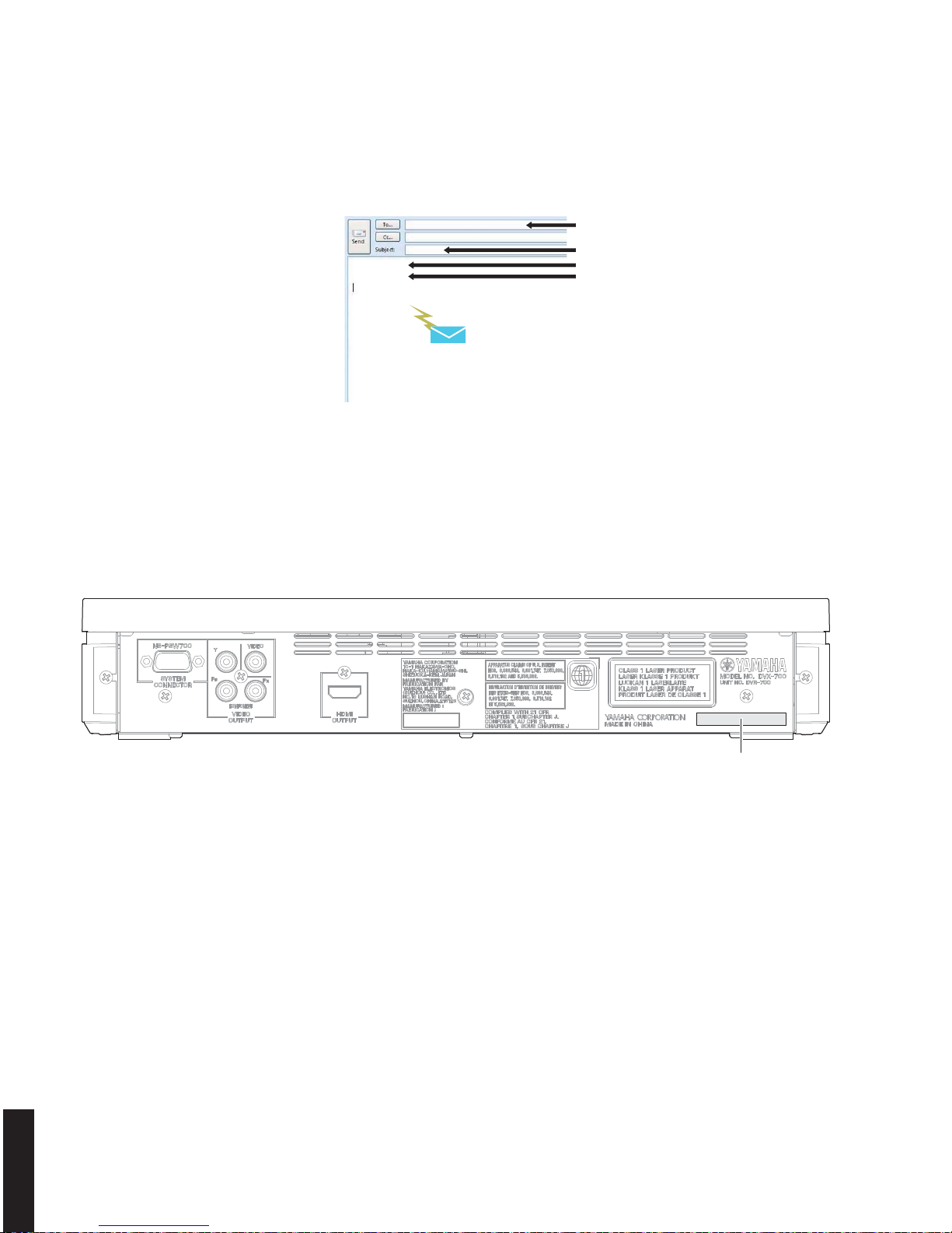
T015018XZ
Send this email to YCJ
ycav-keycontrol@gmx.yamaha.com
ycav-keycontrol@gmx.yamaha.com
DVR-700
008000215
Model name
Serial number of DVR-700
ID number (device key)
DVR-700
Rear view
Serial number
■ SERVICE PRECAUTIONS
When DVD MODULE P.C.B. of the DVR-700 is replaced, the serial number and new ID number (device key) must be reported to YCJ (Yamaha Corporation Japan) by email. (Fig. 1)
Fig. 1
● Check the Serial Number
The serial number “SER.No.xxxxxxx” can be found at the rear panel of the DVR-700. (Fig. 2)
Fig. 2
Email: ycav-keycontrol@gmx.yamaha.com
17
DVR-700/NS-PSW700/NS-P700
DVR-700/
NS-PSW700/NS-P700
1-1VOL1 DVD:-setting- xxx:DVDIDCLR
3
2
1
New ID number (device key)
* The displayed “008000215” is an
example.
ID Number ?
<CLEAR> Exit
008000215
*********
(Player's ID Number Setting)
Input ID Number !
Compare
2. Press “ (down) ” key once to select main menu 22 DVD SETTING.
3. Press “
(right) ” key twice to select sub-menu 22-3 DVD ID CLR.
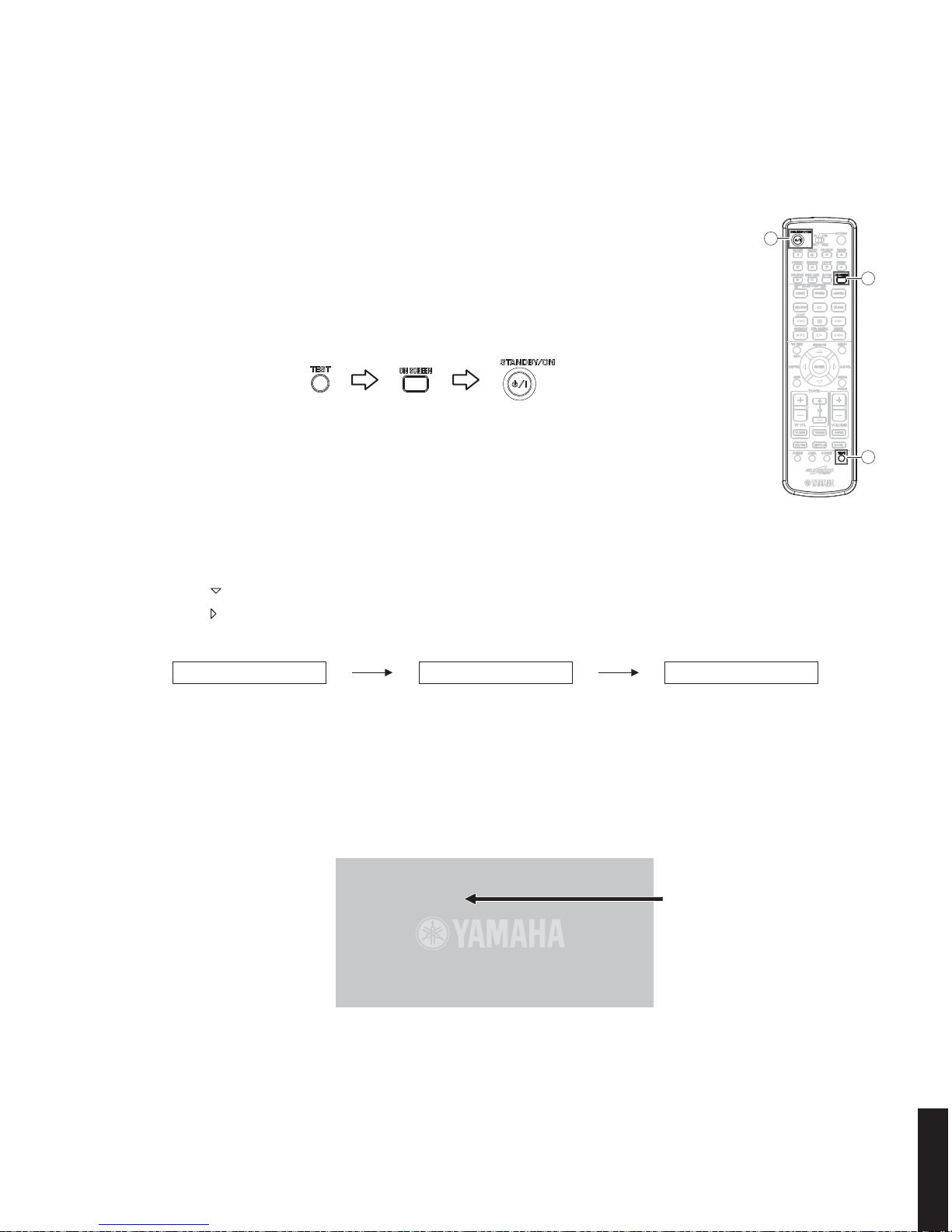
6. To exit the self-diagnostic function, press “STANDBY/ON” key to turn off the power.
4. Press “ENTER” key once. Wait about 15 seconds.
5. New ID number (device key) will appear on TV monitor screen as shown below.
Note: While the ID number is displayed, never operate any keys on the remote control.
Fig. 4
Fig. 5
● Check the New ID Number (Device key)
Connection
Connect the VIDEO OUT terminal of DVR-700 to the VIDEO IN terminal of the TV monitor with a video pin cable.
Fig. 3
Self-diagnostic function starting display Main menu 22 – DVD SETTING sub-menu 22-3 – DVD ID CLR
Operation Procedure
Perform following steps while watching the TV monitor screen and using the keys on the remote
control.
1. With this unit in the standby mode, press the keys on the remote control in the order as shown
below.
The self-diagnostic function is activated. (Fig. 3)
18
DVR-700/NS-PSW700/NS-P700
DVR-700/
NS-PSW700/NS-P700
Side panel R
Top cover
Frame top
Side panel L
Hook
1
1
3
3
3
2
3
4
4
4
4
2
5
Remove the screw located
at the back.
Rear side
Front side
Bottom view
3
3 3
3 3
5335
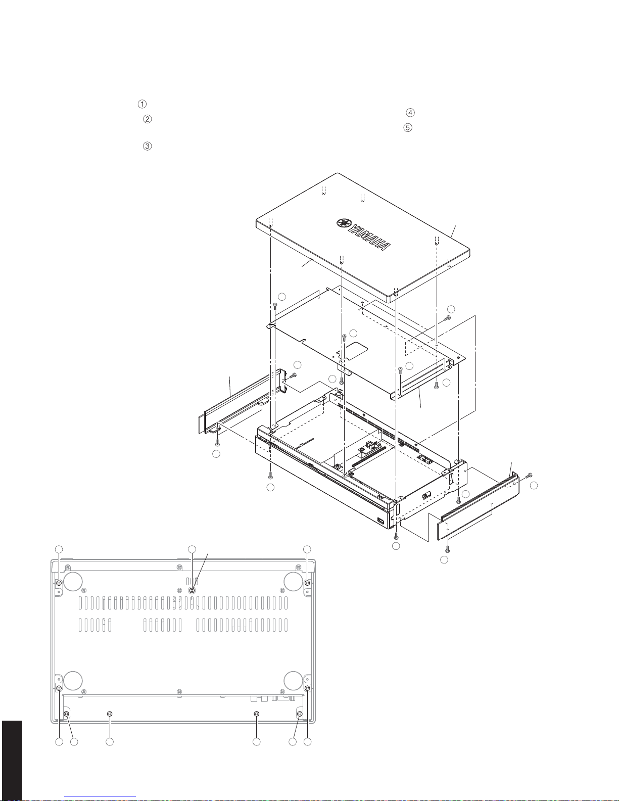
■ DVR-700 DISASSEMBLY PROCEDURES
(Remove parts in the order as numbered.)
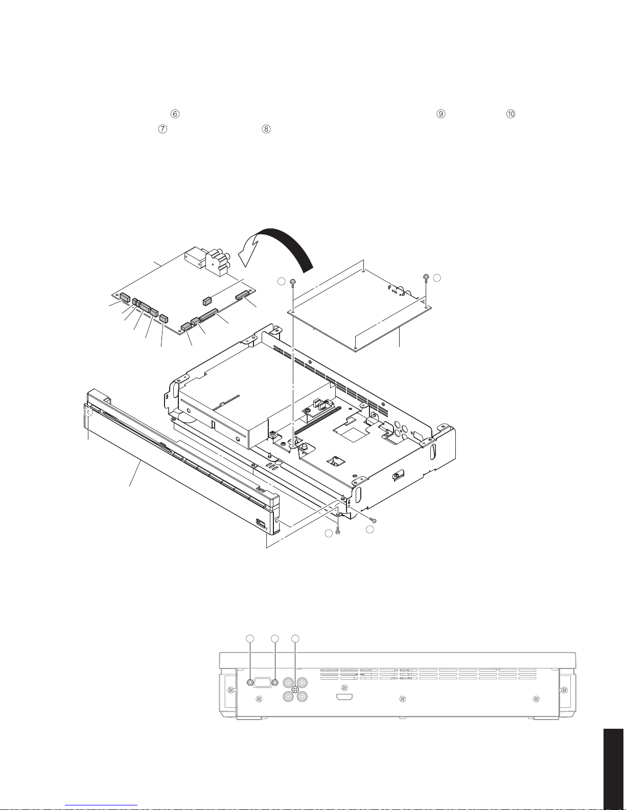
1. Removal of Top Cover
a. Remove 3 screws ( ). Remove the side panel L. (Fig. 1)
b. Remove 3 screws (
). Remove the side panel R.
(Fig. 1)
c. Remove 7 screws (
). (Fig. 2)
d. Release a hook. Remove the top cover. (Fig. 1)
2. Removal of Frame Top
a. Remove 7 screws ( ). (Fig. 1)
b. Remove 2 screws (
). (Fig. 2)
c. Remove the frame top. (Fig. 1)
Fig. 1
Fig. 2
19
DVR-700/NS-PSW700/NS-P700
DVR-700/
NS-PSW700/NS-P700
FRONT (1) P.C.B.
Front panel ass'y
FRONT (1) P.C.B.
CB317
CB321
CB319
CB311
CB314
CB315
CB320
CB313
CB304
CB301
CB305
Hook
6
6
9
10
Rear view
8 8 7
3. Removal of FRONT (1) P.C.B.
a. Remove 4 screws ( ). (Fig. 3)
b. Remove screw (
) and 2 jack screws ( ). (Fig. 4)
c. Turn over the FRONT (1) P.C.B.. (Fig. 3)
d. Remove CB301, CB304-305, CB311, CB313-315,
CB317, CB319 and CB320-321. (Fig. 3)
e. Remove the FRONT (1) P.C.B.. (Fig. 3)
4. Removal of Front Panel Ass’y
a. Remove 3 screws ( ) and screw ( ). (Fig. 3)
b. Release a hook. Remove the front panel ass’y. (Fig. 3)
Fig. 3
Fig. 4
20
DVR-700/NS-PSW700/NS-P700
DVR-700/
NS-PSW700/NS-P700
Use a clip or the like to ground
the unit.
Clip
Terminal side
17 mm
(0.67")
DVD module P.C.B.
OPERATION (3) P.C.B.
CN966
CN964
CN965
CB9
DVD mechanism unit
Frame P.C.B.
13
12
13
12
15
14
14
11
11
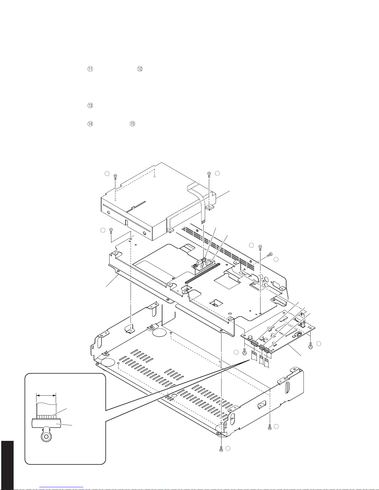
5. Removal of DVD Mechanism Unit and DVD module P.C.B.
a. Remove 6 screws ( ) and 2 screws ( ). (Fig. 5)
b. Remove the DVD mechanism unit , DVD module P.C.B. and frame PCB together. (Fig. 5)
c. Remove CB9 and CN965. (Fig. 5)
d. Remove CN966, and ground the terminal side of the flexible flat cable with a clip or the like. (Fig. 5)
e. Remove 4 screws (
). (Fig. 5)
f. Remove the DVD mechanism unit. (Fig. 5)
g. Remove 4 screws (
) and screw ( ). Fig. 5)
h. Remove CN964. (Fig. 5)
i. Remove the DVD module P.C.B.. (Fig. 5)
Fig. 5
21
DVR-700/NS-PSW700/NS-P700
DVR-700/
NS-PSW700/NS-P700
Metalblade
Cabinet ass'y
Flatblade screwdriver
Side grille ass'y
Dowels
Driver woofer
Connectors
1
■ NS-PSW700 DISASSEMBLY PROCEDURES
(Remove parts in the order as numbered.)
Disconnect the power cable from the AC outlet.
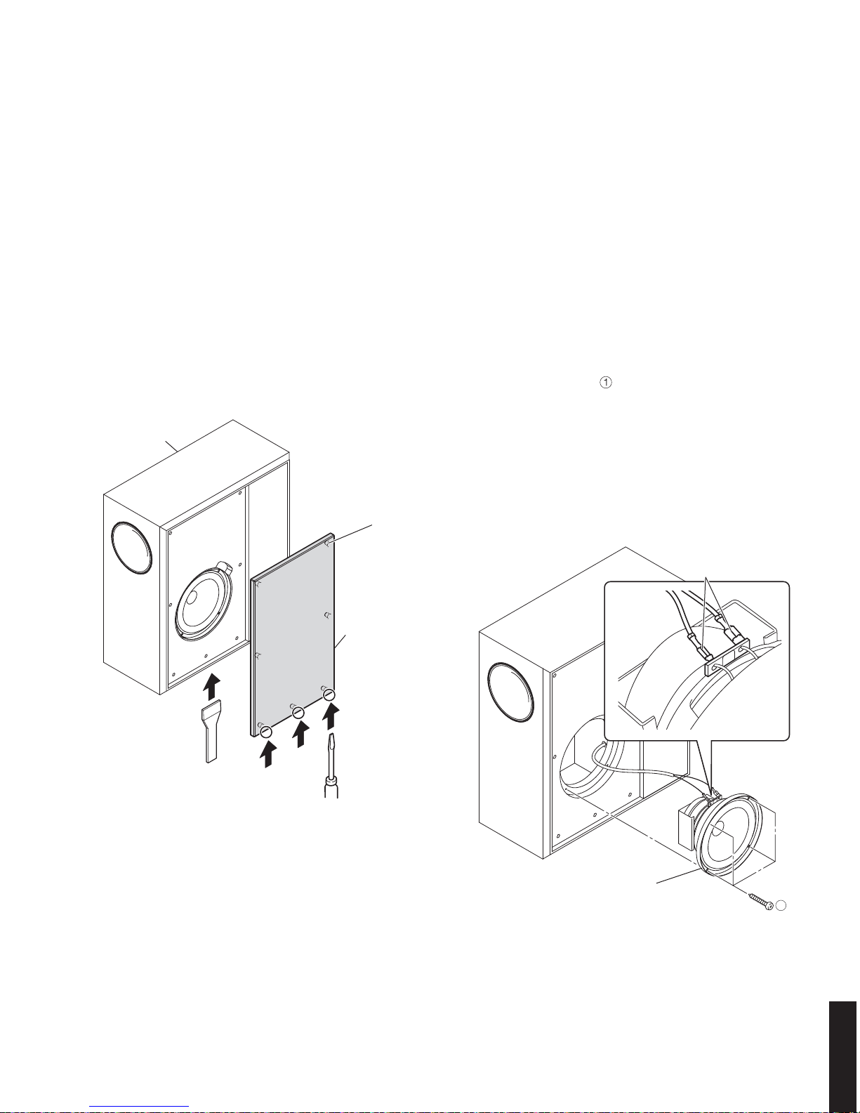
1. Removal of Side Grille Ass’y
* The side grille ass’y is fixed to the NS-PSW700
cabinet ass’y with dowels at 7 locations. As a
flatblade screwdriver is used for removal, use special
care not to cause damage to the NS-PSW700
cabinet ass’y.
a. First, insert a flatblade screwdriver at 3 dowel positions
and push up the side grille ass’y. (Fig. 1)
b. Next, using the metalblade or the like, push the side
grille ass’y upward until it comes off. (Fig. 1)
Fig. 2
Fig. 1
Note:
• Removing the side grille ass’y with the flatblade
screwdriver only without using the metalblade or
the like may cause damage to the side grille ass’y.
• When installing the side grille ass’y, apply quickdrying bond or the like to dowels and then fit them
into dowel holes for secure installation.
(The side grille ass’y will come off easily if its
dowels are fitted into dowel holes without applying
quick-drying bond or the like.)
2. Removal of Driver Woofer
a. Remove 4 screws ( ). (Fig. 2)
b. Pull out the driver woofer.
c. Disconnect the connector connected to the terminal
of the driver woofer. (Fig. 2)
d. Remove the driver woofer. (Fig. 2)

22
DVR-700/NS-PSW700/NS-P700
DVR-700/
NS-PSW700/NS-P700
Rear panel ass'y
CB802
Cover
2
3
3
3
3
3
3
3
3
3 3
3 3 3
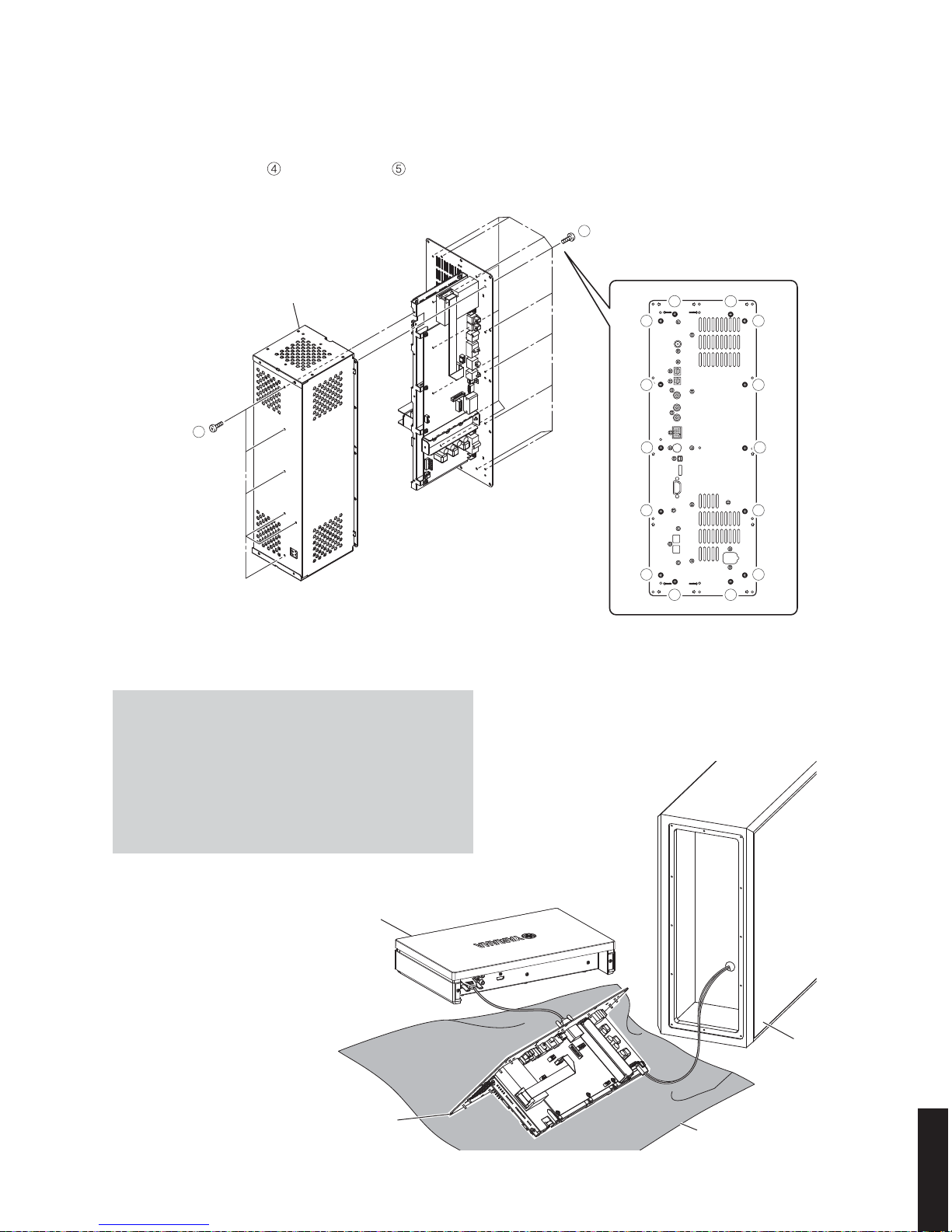
3. Removal of Cover
* If the cover (accessory) is installed, remove it first.
a. Remove 6 screws (
). (Fig. 3)
* Screws (
) are identified with arrow marks (COVER ).
b. Remove the cover. (Fig. 3)
4. Removal of Rear Panel Ass’y
a. Remove 12 screws ( ). (Fig. 3)
* Screws (
) are identified with arrow marks ( ).
b. Pull out the rear panel ass’y. (Fig. 3)
c. Remove CB802. (Fig. 3)
d. Remove the rear panel ass’y. (Fig. 3)
Fig. 3
23
DVR-700/NS-PSW700/NS-P700
DVR-700/
NS-PSW700/NS-P700
Rear panel ass'y
Rubber sheet and cloth
DVR-700
NS-PSW700
Chassis cover ass'y
5
4
4 4
4 4
4
4
4
4
4
4
4
4
44
5. Removal of Chassis Cover Ass’y
a. Remove 14 screws ( ) and 6 screws ( ). (Fig. 4)
b. Remove the chassis cover ass’y. (Fig. 4)
When checking the P.C.B.s:
• Spread the rubber sheet and the cloth.
Then place the rear panel ass’y on the cloth and
check it. (Fig. 5)
• Reconnect all cables (connectors) that have been
disconnected.
• When connecting the flexible flat cable, be careful
with polarity.
Fig. 4
Fig. 5
24
DVR-700/NS-PSW700/NS-P700
DVR-700/
NS-PSW700/NS-P700
Pin No.2 RxD Pin No.2 RxD
Pin No.3 TxD Pin No.3 TxD
Pin No.5 GND Pin No.5 GND
Pin No.7 RTS Pin No.7 RTS
Pin No.8 CTS Pin No.8 CTS
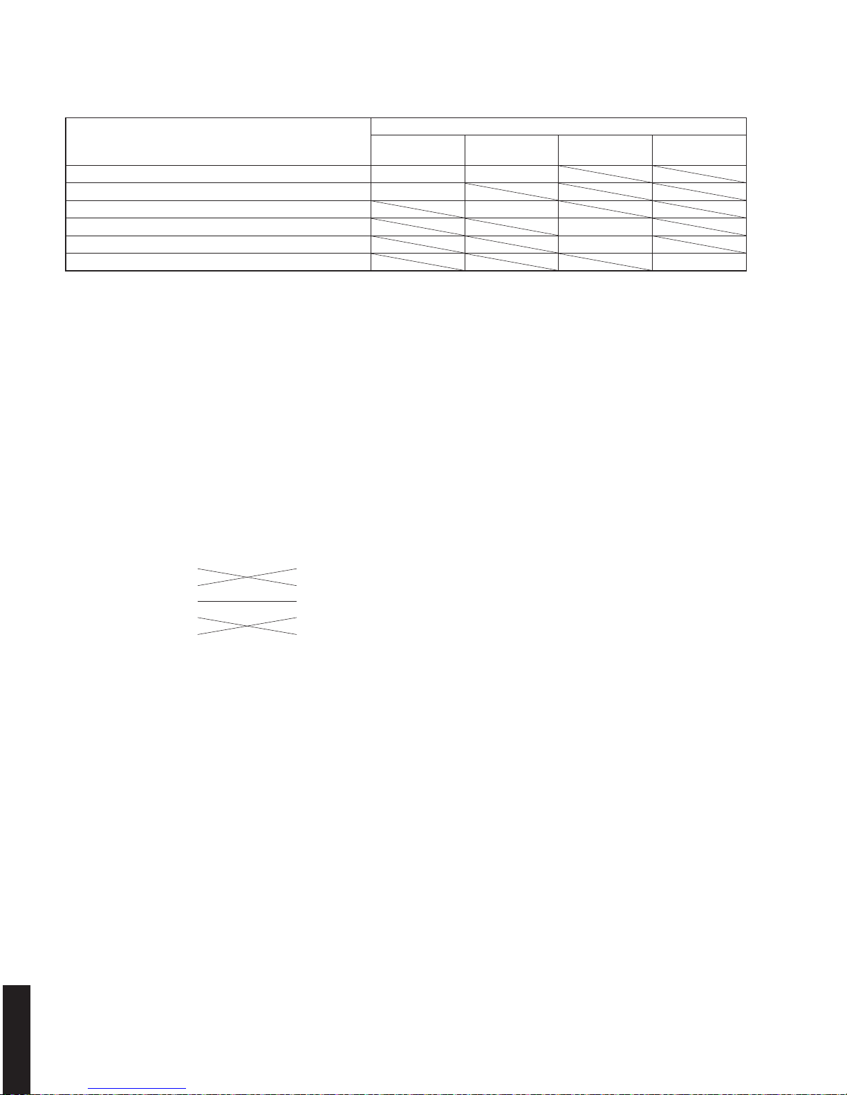
When replacing the following parts, be sure to write the latest firmware.
Replaced parts
Write the latest firmware to
Main
Microprocessor
DSP
Sub-
Microprocessor
Module Board
MAIN P.C.B. (NS-PSW700) yes yes
IC500 (Main microprocessor) of MAIN P.C.B. (NS-PSW700) yes
IC303 (DSP (TI) flash ROM) of MAIN P.C.B. (NS-PSW700) yes
FRONT P.C.B. (DVR-700) yes
IC303 (Sub-microprocessor) of FRONT P.C.B. (DVR-700) yes
DVD module P.C.B. (DVR-700) yes
■ UPDATING FIRMWARE
● Required tools
• Windows 98/2000/Me/XP, PC with a serial port (RS232C)
• Firmware downloader program
DSP_FLASHER_v3.0.exe : for main microprocessor
DSP_FLASHER_v2.7.exe : for DSP (TI FLASH ROM)
FlashSta.exe : for sub-microprocessor
• Firmware
D700_xxxxx.mot : for main microprocessor
DVX700_data1_verx_xx.hex : for DSP (TI FLASH ROM)
D700S_xxxx.mot : for sub-microprocessor
S8CAxxxx.BIN : for module board
• RS232C cross cable “D-sub 9 pin female”
(Specifications)
• RS232C conversion adaptor (Part No.: WR492800)
●
Preparation
1. For writing to the main microprocessor, DSP and sub-microprocessor:
Download firmware upgrading program and firmware from the specified source to the same folder of the PC.
2. For writing to the module board:
Make the Firmware CD by writing the firmware of module board into the root folder of the CD-R.
Set the CD volume label to “PIONEER”.
●
Precautions
• While writing firmware, keep the other application software on the PC closed.
It is also recommended to keep the software on the task tray closed as well.
• Do not turn off the power while writing firmware.
●
Confirmation of firmware version and checksum
Before and after writing firmware, check the firmware version and checksum by using the self-diagnostic function
menu.
1. Start up the self-diagnostic function and select “11. CPU INFORMATION” menu.
2. Have the firmware version and checksum displayed by using sub-menu.
For more information, refer to “SELF-DIAGNOSTIC FUNCTION”.
25
DVR-700/NS-PSW700/NS-P700
DVR-700/
NS-PSW700/NS-P700
SW301
FLASH
UCOM
OTHER
SW301
FLASH
UCOM
OTHER
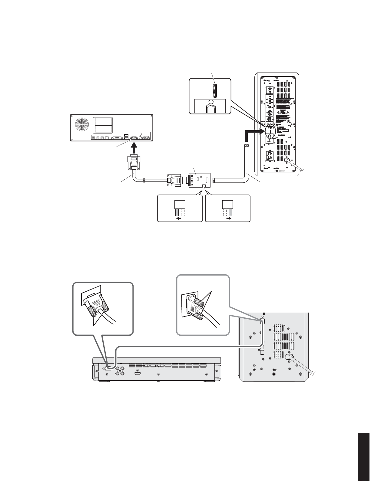
Serial port (RS232C)
RS232C cross cable
For main microprocessor For DSP
Flexible flat cable (9P)
RS232C conversion adaptor
PC
Writing port
NS-PSW700 rear panel
Tighten the screws.
DVR-700
NS-PSW700
Tighten the screws.
System cable
●
Connection Diagrams
Connection Diagram 1
Connection Diagram 2
26
DVR-700/NS-PSW700/NS-P700
DVR-700/
NS-PSW700/NS-P700
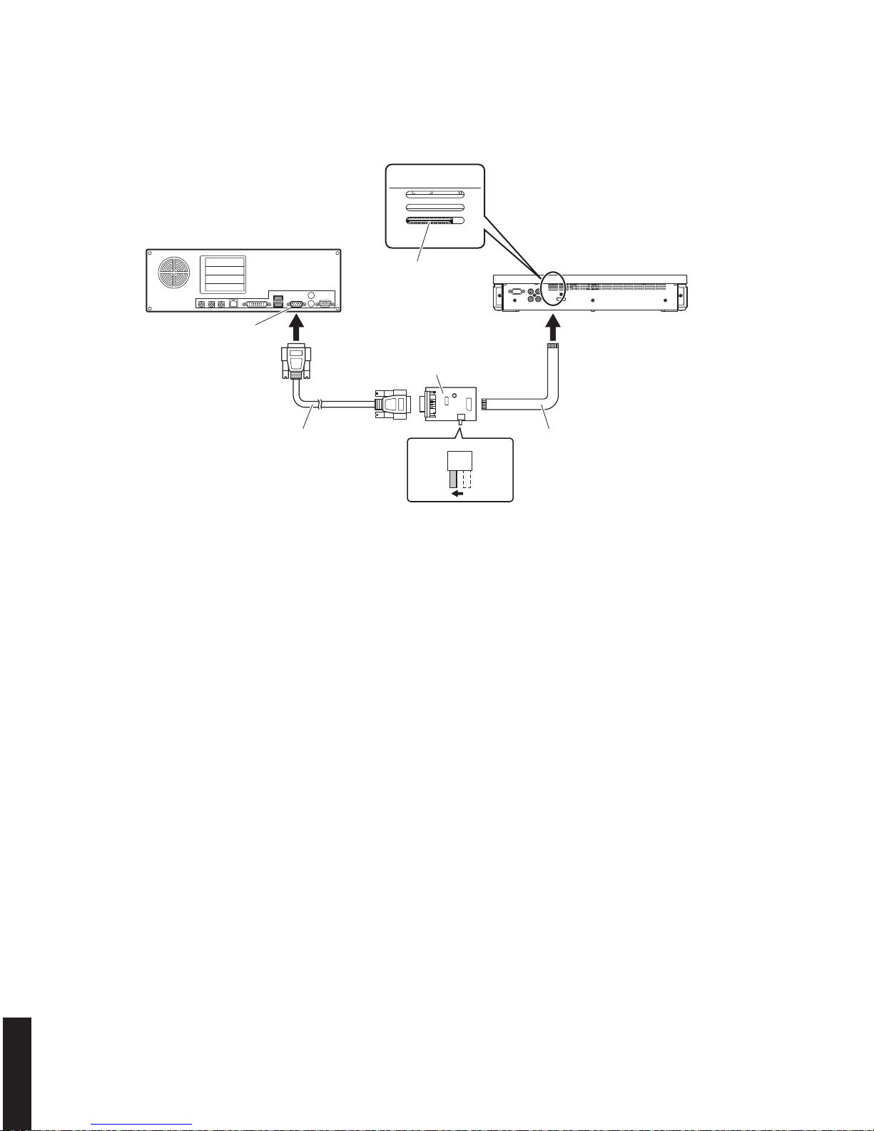
SW301
FLASH
UCOM
OTHER
Serial port (RS232C)
RS232C cross cable
RS232C conversion adaptor
PC
Writing port
DVR-700 rear panel
Flexible flat cable (9P)
Connection Diagram 3
27
DVR-700/NS-PSW700/NS-P700
DVR-700/
NS-PSW700/NS-P700
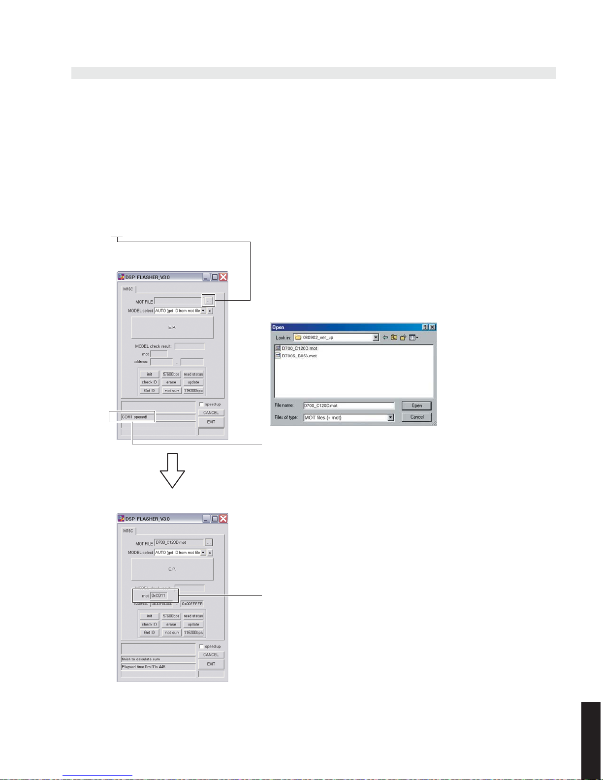
Check to make sure that the serial port is open.
If “COM x opened!” is not displayed, it is possible that 232C port of the
PC has a problem.
The checksum of the ROM code is displayed in the frame of “mot sum:”
(to be used for confirmation after writing)
When the mot file is loaded
Writing to the Main Microprocessor
Connection
1. Connect the writing port of NS-PSW700 to the serial port (RS232C) of the PC with RS232C cross cable, RS232C
conversion adaptor and flexible flat cable. (See connection diagram 1)
2. Set the switch (SW301) of RS232C conversion adaptor to the “FLASH UCOM” side. (See connection diagram 1)
Operation procedures
1. Start up “DSP_FLASHER_v3.0.exe”.
“DSP FLASHER_V3.0” is displayed. (Fig. 1)
2. Select the firmware.
Click [...]. (Fig. 1)
Select “D700_xxxxx.mot”. (Fig. 1)
Fig. 1
3. Connect the power cable of the NS-PSW700 to the AC outlet.
28
DVR-700/NS-PSW700/NS-P700
DVR-700/
NS-PSW700/NS-P700
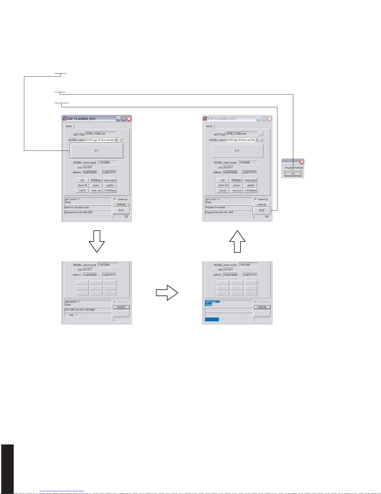
Fig. 2
4. Click [E.P.] to start writing. (Fig. 2)
5. When writing is completed, “Program Finished!” is displayed. (Fig. 2)
Click [OK]. (Fig. 3)
6. Click [EXIT] to end “DSP FLASHER_v3.0.exe”. (Fig. 2)
7. Disconnect the power cable of the NS-PSW700 from the AC outlet.
29
DVR-700/NS-PSW700/NS-P700
DVR-700/
NS-PSW700/NS-P700
Writing to DSP
Connection
1. Connect the writing port of the NS-PSW700 to the serial port (RS232C) of the PC with RS232C cross cable, RS232C
conversion adaptor and flexible flat cable. (See connection diagram 1)
2. Set the switch (SW301) of RS232C conversion adaptor to the “OTHER” side. (See connection diagram 1)
3. Connect the DVR-700 and the NS-PSW700 with the system cable (D-sub 15pin cable) supplied with this unit. (See
connection diagram 2)
Operation procedures
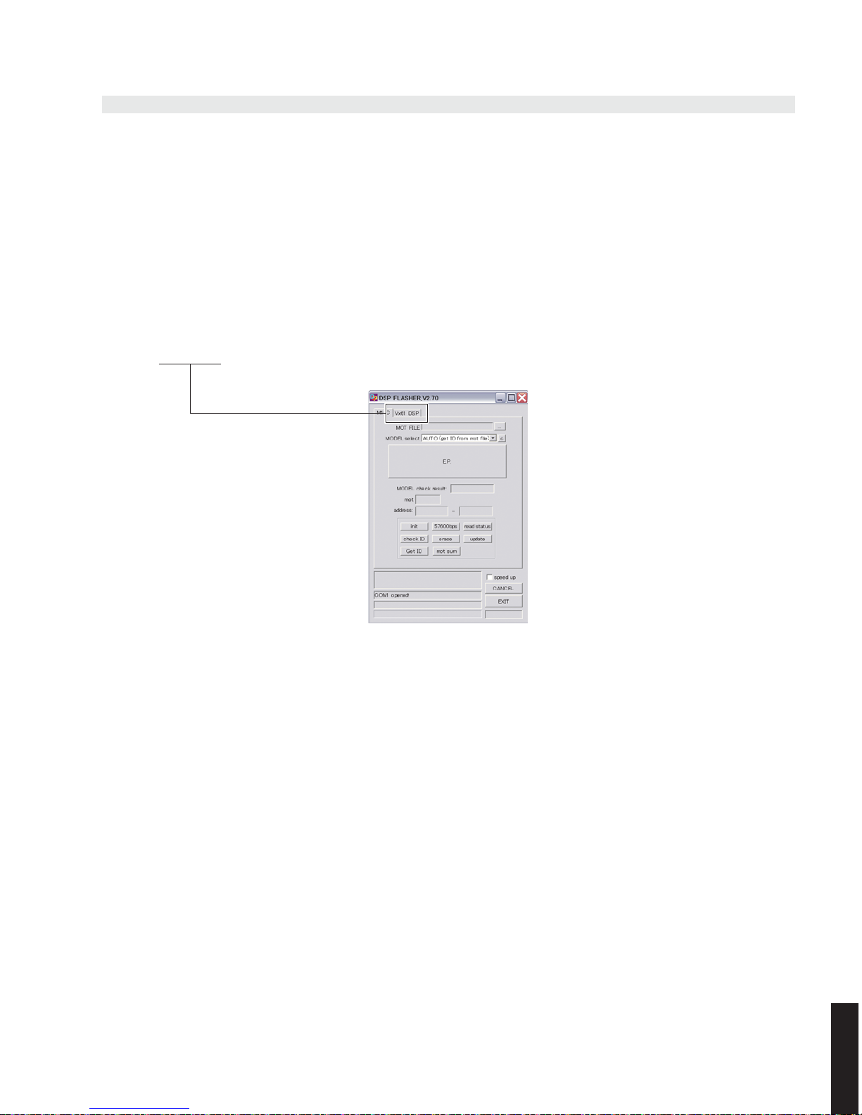
1. Start up “DSP_FLASHER Ver2.7.exe”.
“DSP FLASHER_V2.70” is displayed. (Fig. 1)
2. Click [Vx61 DSP]. (Fig. 1)
Fig. 1
30
DVR-700/NS-PSW700/NS-P700
DVR-700/
NS-PSW700/NS-P700
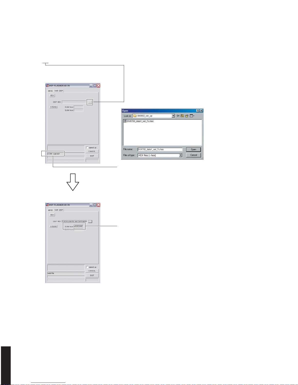
Check to make sure that the serial port is open.
If “COM x opened!” is not displayed, it is possible that 232C port of the
PC has a problem.
The checksum of the ROM code is displayed in the frame of “SUM from
FILE” (to be used for confirmation after writing)
When the hex file is loaded
3. Select the firmware.
Click [...]. (Fig. 2)
Select “DVX700_data1_verx_xx.hex”. (Fig. 2)
4. Connect the power cable of the NS-PSW700 to the AC outlet.
5. Make sure that the DVR-700 is in the standby mode.
6. Start up the self-diagnostic function mode by pressing the “TEST” key, “ON SCREEN” key and “STANDBY/ON” key on
the remote control in order.
7. Select the “15-1 DSP STBY” menu by pressing the “ ▲ (up) ” (Forward) key and “ ▼ (down) ” (Reverse) key on the
remote control.
Fig. 2
 Loading...