

Page 1

®
YAMAHA
AUTHORIZED
PRODUCT MANUAL
MULTITRACK CASSETTE RECORDER
Page 2
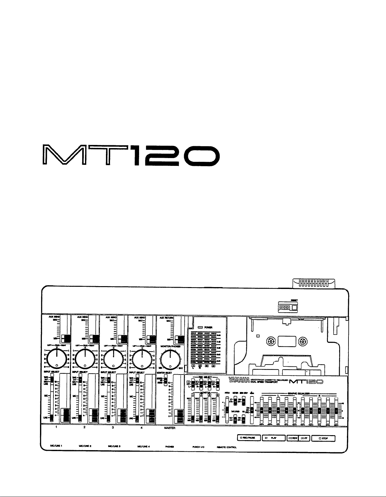
YAMAHA
MULTITRACK CASSETTE RECORDER
OPERATION MANUAL
Page 3
ll
Explanation of Graphical Symbols
The exclamation point within an equilateral triangle is
intended to alert the user to the presence of important
operating and maintenace (servicing) instructions in the
literature accompanying the product.
The lightning flash with arrowhead symbol within an
equilateral triangle is intended to alert the user of the
presence of uninsulated “dangerous voltage” within
the product’s enclosure that may be of sufficient mag-
nitude to constitute a risk of electric shock to persons.
SAFETY INSTRUCTIONS (PREPARED IN ACCORDANCE WITH UL STANDARD 1270)
1.
Read Instructions—All the safety and operating instructions
should be read before the appliance is operated.
Retain Instructions—The safety. and operating instructions
2.
should be retained for future reference.
Heed Warnings—All warnings on the appliance and in the
3.
operating instructions should be adhered to.
4.
Follow Instructions—All operating and use instructions should
be followed.
Water and Moisture—The appliance should not be used near
5.
water—for example, near a bathtub, or near a swimming
pool, and the like.
Carts and Stands—The appliance
6.
should be used only with a cart or
stand that is recommended by the
manufacturer.
6A.
An appliance and cart combination
should be moved with care. Quick
stops, excessive force, and uneven
surfaces may cause the appliance
and cart combination to overturn.
7.
Wall or Ceiling Mounting—The appliance should be mounted
to a wall or ceiling only as recommended by the manufacturer.
8.
Ventilation—The appliance should be situated so that its
location or position does not interfere with its proper ventilation. For example, the appliance should not be situated on
a bed, sofa, rug, or similar surface that may block the ventilation openings; or placed in a built-in installation, such
as a bookcase or cabinet that may impede the flow of air
through the ventilation openings.
9.
Heat—The appliance should be situated away from heat
sources such as radiators, heat registers, stoves, or other
appliances (including amplifiers) that produce heat.
10.
Power Sources—The appliance should be connected to a
power supply only of the type described in the operating
instructions or as marked on the appliance.
Grounding or Polarization—The precautions that should be
11.
taken so that the grounding or polarization means of an
appliance is not defeated.
12.
Power-Cord Protection—Power-supply cords should be routed
so that they are not likely to be walked on or pinched by
items placed upon or against them, paying particular attention to cords at plugs, convenience receptacles, and the point
where they exit from the appliance.
13.
Cleaning—The appliance should be cleaned only as recommended by the manufacturer.
14.
Nonuse Periods—The power cord of the appliance should
be unplugged from the outlet when left unused for a long
period of time.
15.
Object and Liquid Entry—Care should be taken so that ob-
jects do not fall and liquids are not spilled into the enclo-
sure through openings.
16.
Damage Requiring Service—The appliance should be serviced by qualified service personnel when:
A. The power-supply cord or the plug has been damaged;
or
B. Objects have fallen, or liquid has been spilled into the
appliance; or
C.
The appliance has been exposed to rain, or
D.
The appliance does not appear to operate normally or
exhibits a marked change in performance; or
E.
The appliance has been dropped, or the enclosure dam-
aged.
17.
Servicing—The user should not attempt service the appliance beyond that described in the operating instructions.
Page 4

FCC INFORMATION (U.S.A.)
1.
IMPORTANT NOTICE: DO NOT MODIFY THIS UNIT!
This product, when installed as indicated in the instructions contained in this manual, meets FCC requirements. Modifications not expressly approved by
Yamaha may void your authority, granted by the FCC, to use the product.
2.
IMPORTANT: When connecting this product to accessories and/or another product use only high quality shielded cables. Cable/s supplied with this
product MUST be used. Follow all installation instructions. Failure to follow instructions could void your FCC authorization to use this product in the USA.
3.
NOTE: This product has been tested and found to comply with the requirements listed in FCC Regulations, Part 15 for Class “B” digital devices,
Compliance with these requirements provides a reasonable level of assurance that your use of this product in a residential environment will not result in
harmful interference with other electronic devices. This equipment generates/uses radio frequencies and, if not installed and used according to the
instructions found in the users manual, may cause interference harmful to the operation of other electronic devices. Compliance with FCC regulations
does not guarantee that interference will not occur in all installations. If this product is found to be the source of interference, which can be determined
by turning the unit “OFF” and “ON”, please try to eliminate the problem by using one of the following measures:
Relocate either this product or the device that is being affected by the interference.
Utilize power outlets that are on different branch (circuit breaker or fuse) circuits or install AC line filter/s.
In the case of radio or TV interference, relocate/reorient the antenna. If the antenna lead-in is 300 ohm ribbon lead, change the lead-in to co-axial type
cable.
If these corrective measures do not produce satisfactory results, please contact the local retailer authorized to distribute this type of product. If you can
not locate the appropriate, please contact Yamaha Corporation of America, Electronic Service Division, 6600 Orangethorpe Ave. Buena Park, CA 90620
* This applies only to products distributed by YAMAHA CORPORATION OF AMERICA.
CANADA
THIS DIGITAL APPARATUS DOES NOT EXCEED THE “CLASS B” LIMITS FOR RADIO NOISE EMISSIONS FROM DIGITAL APPARATUS SET OUT IN
THE RADIO INTERFERENCE REGULATION OF THE CANADIAN DEPARTMENT OF COMMUNICATIONS.
LE PRESENT APPAREIL NUMERIQUE N’EMET PAS DE BRUITS RADIOELECTRIQUES DEPASSANT LES LIMITES APPLICABLES AUX APPAREILS
NUMERIQUES DE LA “CLASSE B” PRESCRITES DANS LE REGLEMENT SUR LE BROUILLAGE RADIOELECTRIQUE EDICTE PAR LE MINISTERE
DES COMMUNICATIONS DU CANADA.
* This applies only to products distributed by YAMAHA CANADA MUSIC LTD.
Dette apparat overholder det gaeldende EF-direktiv
vedrørende radiostøj.
Cet appareil est conforme aux prescriptions de la
directive communautaire 87/308/CEE.
Diese Geräte entsprechen der EG-Richtlinie 82/
499/EWG und/oder 87/308/EWG.
This product complies with the radio frequency
interference requirements of the Council Directive 82/499/EEC and/or 87/308/EEC.
Questo apparecchio è conforme al D.M.13 aprile
1989 (Direttiva CEE/87/308) sulla soppressione
dei radiodisturbi.
Este producto está de acuerdo con los requisitos
sobre interferencias de radio frequencia fijados
por el Consejo Directive 87/308/CEE.
YAMAHA CORPORATION
Connecting the Plug and Cord
IMPORTANT. The wires in this mains lead are coloured in accordance with the following
code:
As the colours of the wires in the mains lead of this apparatus may not correspond with the
coloured markings identifying the terminals in your plug proceed as follows:
The wire which is coloured BLUE must be connected to the terminal which is marked with
the lettcr N or coloured BLACK.
The wire which is coloured BROWN must be connected to the terminal which is marked
with the letter L or coloured RED.
Making sure that neither core is connected to the earth terminal of the three pin plug.
IMPORTANT NOTICE FOR THE UNITED KINGDOM
BLUE : NEUTRAL
BROWN : LIVE
* This applies only to products distributed by YAMAHA - KEMBLE MUSIC (U.K.) LTD.
WARNING: CHEMICAL CONTENT NOTICE!
The solder used in the manufacture of this product contains LEAD. In addition, the electrical/electronic and/or plastic (where applicable) components may
also contain traces of chemicals found by the California Health and Welfare Agency (and possibly other entities) to cause cancer and/or birth defects or other
reproductive harm.
DO NOT REMOVE ANY ENCLOSURE COMPONENTS! There are no user serviceable parts inside, All service should be performed by a service representative
authorized by Yamaha to perform such service.
IMPORTANT MESSAGE: Yamaha strives to produce products that are both user safe and environmentally “friendly”. We sincerely believe that our products
meet these goals. However, in keeping with both the spirit and the letter of various statutes we have included the messages shown above and others in various
locations in this manual.
*
This applies only to products distributed by YAMAHA CORPORATION OF AMERICA.
1
Page 5

CONGRATULATIONS!
Your MT120 Multitrack Cassette Recorder is a powerful recording tool that will enable you
to work with sound in many ways. No other multitrack cassette recorder offers the straightforward
simplicity and ease-of-use of the MT120. Whether you need to record acoustic instruments or
voice using microphones, electronic instruments and line-level sources, or a creative blend of
the two, the MT120 makes the process of building tracks extraordinarily smooth and simple.
You can simply record and remix four tracks, or use the multitrack “ping-pong” recording
technique to individually record up to ten independent parts — adding sound layer by layer
until you create exactly the arrangement and texture your imagination demands with its
ability to record on all four tracks at once, or in any combination, MT120 is the ideal choice
for recording bands or layering tracks at home. And, because it’s a YAMAHA, you know that
the MT120 will give you the very finest sound quality and overall performance available.
In order to make use of the MT120’s many features and obtain maximum performance, we
urge you to read this operation manual thoroughly — and keep it in a safe place for later
reference.
CONTENTS
PRECAUTIONS
THE CONTROLS AND CONNECTORS 4
MT120 CONTROLS AND THEIR FUNCTIONS
CONNECTION EXAMPLES
ABOUT CASSETTE TAPES
THE RECORDING PROCESS
RECORDING THE FIRST TRACK
STEP 1:
STEP 2:
STEP 3: SETTING RECORDING LEVELS
STEP 4:
OVERDUBBING
PING-PONG RECORDING
A PING-PONG RECORDING EXAMPLE 18
MIXDOWN
USING THE GRAPHIC EQUALIZER
USING THE TAPE OUT JACKS
USING THE AUX SEND/RETURN LOOP
PUNCH-IN/OUT RECORDING
MAINTENANCE
SPECIFICATIONS
BLOCK DIAGRAM
CHANNEL-TO-TRACK ASSIGNMENT
MONITOR SETUP
RECORD
10
11
12
13
13
14
15
15
16
17
19
20
21
22
23
24
25
79
3
5
2
Page 6

PRECAUTIONS
1.
AVOID EXCESSIVE HEAT, HUMIDITY, DUST
AND VIBRATION
Keep the unit away from locations where it is likely to
be exposed to high temperatures or humidity — such
as near radiators, stoves, etc. Also avoid locations
which are subject to excessive dust accumulation or
vibration which could cause mechanical damage.
2.
AVOID PHYSICAL SHOCKS
Strong physical shocks to the unit can cause damage.
Handle it with care.
3.
DO NOT OPEN THE CASE OR ATTEMPT
REPAIRS OR MODIFICATION YOURSELF
This product contains no user-serviceable parts. For
other than routine cleaning, refer maintenance to qualified
YAMAHA personnel. Opening the case and/or tamper-
ing with the internal circuitry will void the warranty.
4.
MAKE SURE POWER IS OFF BEFORE MAK-
ING OR REMOVING CONNECTIONS
Always turn the power OFF prior to connecting or dis-
connecting cables. This is important to prevent damage
to the unit itself as well as other connected equipment.
7. ALWAYS USE THE CORRECT POWER SUPPLY
The MT120 is sold with the appropriate power specifications for the local area (power supply voltage and
power consumption are listed on the bottom panel). If
you move to a different area that might have a different
AC mains voltage, however, be sure to check with your
nearest YAMAHA dealer before using your MT120.
8.
KEEP THE HEADS AND TAPE PATH CLEAN
To ensure consistent high performance and sound quality
from your MT120, it is important to clean the head and
tape path regularly (ideally before each recording ses-
sion). To do this, use a cleaning kit specifically designed for use with cassette tape equipment.
9.
USE ONLY HIGH-QUALITY CHROME CAS-
SETTE TAPE
The MT120 is designed for use with CrO2 (chrome)
formulation tape, and will not provide proper performance
with any other type of tape. Always choose cassette
tapes from a reliable manufacturer.
5. HANDLE CABLES CAREFULLY
Always plug and unplug cables — including the AC
— by gripping the connector, not the cord.
cord
6.
CLEAN WITH A SOFT DRY CLOTH
Never use solvents such as benzine or thinner to clean
the unit. Wipe clean with a soft, dry cloth.
3
Page 7
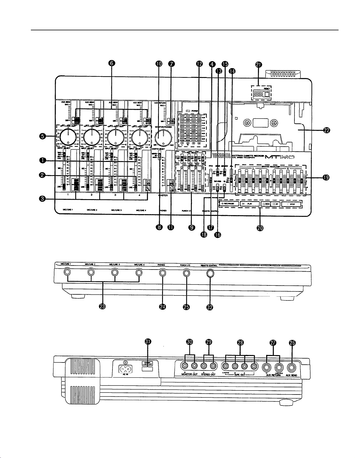
THE CONTROLS AND CONNECTORS
— CONTROL PANEL —
— FRONT PANEL —
— REAR PANEL —
4
MT120 MULTlTRACK CASSETTE RECORDER
Page 8
MT120 CONTROLS AND THEIR FUNCTIONS
[Note] The terms “channel” and “track”: In this owner’s manual, the term “channel” refers to the circuitry and
controls required to process one input source. MT120’s mixer section has four “channels.” The term “track”
refers to the magnetic bands on tape used to store signals recorded by MT120’s recorder section. Since
MT120 records four separate bands of audio on tape, it is a four-“track” recorder.
INPUT SELECT Switches
The INPUT SELECT switches are used to select the
input source for each of the four channels.
TAPE:
OFF:
MIC/LINE:
[Note] All channels which are not in use should be set
Select this position to play back already recorded material. When selected, mixer channel 1
will receive playback from track 1; channels 2, 3,
& 4 will receive tracks 2, 3, & 4 respectively.
In this position, the channel receives no input
signal.
In this position, the channel can receive a
microphone, keyboard, or other line-level signal
which is connected to the input jack.
to “OFF” position.
MIC/LINE Gain Controls
The gain controls adjust the sensitivity of the channel
inputs to accept a wide range of signal levels — from
line to microphone. The gain controls are used in conjunction for the input faders to set the optimum recording level with a wide range of sources (see “SETTING
RECORDING LEVELS” on page 15).
[Note] A gain control only affects the level of the signal
connected to the input jack.
Input Faders
The input faders are used to adjust the level (volume)
of the corresponding mixer channel’s signal, whether it
comes from a source plugged into an input jack or from
the MT120’s recorder section. (The INPUT SELECT
switches are used to choose between the two.) The
faders are used to set up the optimum levels when
recording, and to balance (mix) the sound from the
recorder’s tracks when playing back a recording.
Noise and distortion are at their lowest at input fader
level “7”.
[Note]
When any of the REC SELECT switches are set
to a position other than OFF, the red indicator
LED of the transport REC/PAUSE button will flash,
indicating that the MT120 is set up to record.
Recording will commence when the PLAY button
is pressed after pressing the REC/PAUSE button. If all REC SELECT switches are set to OFF,
the unit will not record even if the REC/PAUSE
and PLAY buttons are pressed.
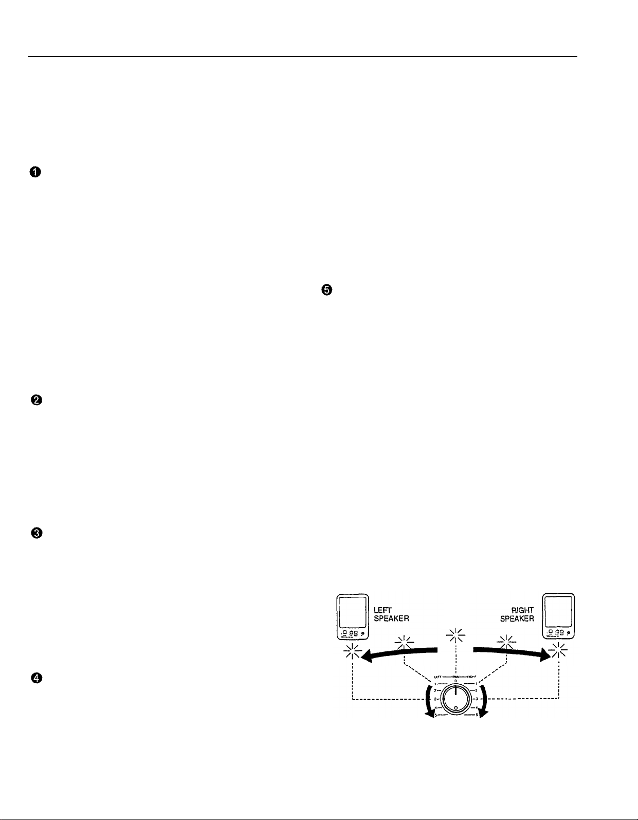
PAN Controls
The PAN controls assign the signal from the corre-
sponding mixer channel to any desired position in the
“stereo sound field”. If a PAN control is set to the
maximum “LEFT” position, the signal from, that channel
will appear only at the left-channel MT120 output (STEREO
OUT L). If the PAN control is set fully RIGHT, the
signal will appear only at the STEREO OUT R output
jack. If a PAN control is set to its center position, then
the signal from that channel will appear equally at both
the left- and right-channel outputs, and the sound will
appear to come from the center of the stereo sound
field, a point midway between the two stereo speakers.
By varying the level of the signal sent to the left-and
right-channel outputs, the PAN control can be used to
position the sound at any point in the stereo spectrum.
The PAN controls can also be used during recording to
assign the signal from several channels to a single
track of the recorder section, or to assign a channel to
a differently-numbered recorder track (see “CHANNEL-
TO-TRACK ASSIGNMENT” on page 13).
REC SELECT Switches
The REC SELECT switches are used when recording
to assign (send) the signal from each mixer channel
either directly to the corresponding track of the recorder or to a different track via the PAN controls (see
"CHANNEL-TO-TRACK ASSIGNMENT” on page. 13).
5
Page 9

AUX SEND Controls
The AUX SEND controls are used primarily when adding effects such as reverberation or echo to the sound
of a channel or track. The AUX SEND control on each
mixer channel determines the amount of signal from
that channel sent to the AUX SEND jack. The AUX
SEND jack must be connected to the input of an external signal processor such as the YAMAHA EMP100
Multi-effect Processor (see “USING THE AUX SEND/
RETURN LOOP” on page 22).
AUX RETURN Control
The AUX RETURN control determines the level at which
the signal from an external signal processor is re-
turned and mixed in with the MT120’s main stereo
output signal. The output from an external signal proc-
essor fed by the AUX SEND jack must be connected to
the AUX RETURN jack(s) (see “USING THE AUX SEND/
RETURN LOOP” on page 22).
MASTER Fader
The MASTER fader sets the overall output level of the
MT120 mixer section, and thus the level of the output
signal appearing at the STEREO OUT jacks. The MASTER fader also affects recording level when any of the
mixer section’s channels are assigned to the recorder’s tracks via the PAN controls (see “SETTlNG RECORDING LEVELS” on page 15).
LED Peak Meters
The four LED peak meters accurately display output
levels from the MT120’s four recorder tracks when the
METER switch is set to “4TR”, or meters 1 and 2
display the level of signals appearing at the mixer
section’s stereo outputs (the STEREO OUT jacks) when
the METER switch is set to “ST.”
The LED peak meters are a guide for setting up the
optimum recording levels. (see “SETTING RECORD-
ING LEVELS” on page 15).
MONITOR SELECT Switch
MONITOR: This position is selected to listen to the
four tape tracks. In this position a mix from the
four MONITOR controls is sent to the PHONES
jack and the MONITOR OUT jack.
MIX: This position is selected to hear a combination of
the four tape tracks and input sources connected
to the input jacks. The mix from the MONITOR
controls is combined with the stereo output from
the mixer section and sent to the PHONES jack
and MONITOR OUT jack.
STEREO:
This position is selected to monitor the stereo
output from the mixer section. In this position, the
mix sent to the MONITOR OUT jack and PHONES
jack is the same mix that is sent to the STEREO
OUT jacks.
MONITOR Controls 1 — 4
The four MONITOR controls determine the level of the
signal from the corresponding recorder tracks which is
sent to the PHONES jack and MONITOR OUT jacks
when the MONITOR SELECT switch is set to either
“MONITOR” or “MIX.” The MONITOR controls are primarily used to set up the optimum levels for monitoring
recorded tracks while recording new material
(overdubbing).
MONITOR/PHONES Control
This control is used to set headphone and control room
listening level. It adjusts the level of signal sent to the
PHONES jack and MONITOR OUT jacks with out affecting the signal level appearing at the STEREO OUT
jacks.
6
MT120 MULTITRACK CASSETTE RECORDER
METER Switch
When the METER switch is set to “ST,” meters 1 and 2
display the level of signals appearing at the mixer
section’s stereo outputs (the STEREO OUT jacks). When
set to “4TR,” the four LED peak meters display the
level of the corresponding recorder track signals.
dbx ON/OFF Switch
The dbx switch determines whether the MT120’s internal dbx noise reduction system is ON or OFF. For
normal recording and playback using the MT120, the
dbx switch should be turned ON. This provides a significantly improved signal-to-noise ratio (as much as
85 dB) so your recordings will sound cleaner and have
much less tape hiss.
If dbx noise reduction is to be activated during synchrorecording, set the switch to “SYNC”.
For dbx noise reduction to be effective, it must be
turned ON both during recording and playback.
The dbx switch may be turned OFF when playing back
tapes that were recorded on other equipment and which
are
not
dbx-encoded.
“For Error-free SYNC Recording”
l
When recording the FSK signal, set the Track 4 recording level between 0 and +3dB.
l
For recording and playback of the FSK signal on
Track 4, set the dbx switch to the “SYNC” position.
When the dbx switch is set to “SYNC”, Tracks 1 to
*
3 are set to dbx ON.
l
Do not record signals (music, etc.) other than the
FSK signal on Track 4, when the dbx switch is set to
the “SYNC” position.
l
If other signals (music, etc.) are recorded during recording of the FSK signal, avoid using adjacent tracks,
if possible.
Page 10

ZERO STOP Switch
When the transport is in rewind, the ZERO STOP function automatically stops the tape at a specified location. To set the ZERO STOP point, play the tape to the
desired location and reset the tape counter to ZERO
by pressing the counter reset button. In rewind, with
the ZERO STOP switch “ON”, the transport will stop
when the tape counter reaches the vicinity of “999” (may
deviate due to tape slack). This is particularly handy in
the multitrack “overdub” process when it is necessary
to repeatedly rewind the tape and play from the same
point.
TAPE SPEED Switch
The TAPE SPEED switch selects either the standard
4.8-cm/sec cassette tape speed, or the MT120’s spe-
cial 9.5-cm/sec high tape speed. Use the standard
(4.8) speed when replaying tapes recorded on stand-
ard cassette recorders, or to obtain maximum tape
economy. When you want maximum sound quality, use
the high (9.5) tape speed. The improvement in sound
quality provided by the high tape speed is significant,
and we recommend that you use the high speed for all
important recordings.
[Note] Never change the TAPE SPEED setting while
the tape is running.
PITCH Control
The PITCH control varies tape speed by approx. ± 10%,
making it possible to “tune” material recorded on the
MT120 to match the pitch of musical instruments, or to
slightly lengthen or shorten the running time of a recording to meet specific timing requirements. Tape speed
is normal when the PITCH control is set to its center
click-stop position. Tape speed is increased by sliding
the control towards the “+” end of the scale, and de-
creased by sliding the control towards the “–” end of
the scale.
EQ Switch
This switch turns the graphic equalizer on and off.
Graphic Equalizer
An equalizer is used to tailor the signal to help it stand
out or integrate into a mix. MT120’s graphic equalizer is
a powerful signal shaping tool which allows you to aug-
ment or attenuate signal components up to approx. 10
dB in five frequency bands. The graphic equalizer can
be switched ON to enhance signals as they are recorded
on tape, and again in playback.
[Note] When switched ON, the graphic equalizer can
affect signals being routed to tape via the PAN
controls when the REC SELECT switches which
are set to “L” or “R”. The graphic equalizer will not
affect signals being routed to tape via REC SELECT switches which are set to “1 — 4”.
Transport Controls
These light touch electronic transport controls provide
smooth, sure control of the tape transport functions.
REC/PAUSE Button: When this button is pressed dur-
ing tape stop, the REC mode track will be set to
the record-ready mode. When this button is pressed
during tape recording (first press REC/PAUSE button
and then PLAY button), the recording can be in-
terrupted temporarily. For resuming recording, press
the PLAY button.
REC/PAUSE Indicator:
state (lit, slow/fast/specific blinking, and unlit), the
indicator indicates one of the following 5 modes:
•
Indicator lit: More than one track is set to REC
mode and the REC/PAUSE button has been
pressed (record-ready mode).
Recording of the track set to REC mode is underway
(during recording PLAY indicator will light-up as
well).
• Indicator slowly blinking: More than one track
is set to REC mode and the REC/PAUSE button
has not been pressed.
When pressing PLAY button, the unit will enter
not the recording mode but the playback mode.
•
Indicator fast blinking:
mode.
• Indicator specificly blinking (warning indica-
tion):
The indicator blinks twice in specific intervals.
The foot switch is connected to the PUNCH l/O
jack and all of the REC SELECT switches are
set to “OFF”.
•
Indicator unlit:
mode (PLAY mode).
[Note] Only tracks for which the REC SELECT switch
is set to a recording position will be recorded
when the RECORD mode is activated.
[Note] The RECORD mode cannot be activated if a
cassette is loaded from which the record-prevention tab has been removed.
PLAY Button: Using this button, you can select the 3
functions playback start, recording start, and punch-
in/out start.
• Playback start: Starts the playback of the track
set to PLAY mode (REC SELECT switch set to
OFF).
•
Recording start:
set to REC mode (REC SELECT switch not in
position OFF) when the record-ready mode has
been selected using REC/PAUSE button.
According to its corresponding
Indicates punch-in standby
None of the tracks is set to REC
Starts the recording of the track
7
Page 11

•
Punch-in/out start:
foot switch is connected to PUNCH l/O jack,
even if the record-ready mode has not been acti-
vated using REC/PAUSE button.
PLAY Indicator: According to its state (lit, slow/fast
blinking), this indicator indicates one of the following 3 modes:
• Indicator lit: PLAY button has been pressed.
• Indicator fast blinking: FF button or REW but-
ton has been pressed during playback (CUE/
REVIEW mode).
•
Indicator slowly blinking:
approximately 4 seconds after the POWER switch
has been turned on. (During this period the but-
tons are inoperative.)
Starts punch-in/out when the
Continues blinking for
[Note] Since the MT120 uses the entire width of the
cassette tape to record four tracks, the cassette
can only be recorded on one side. Never change
the TAPE SPEED setting while the tape is running.
REW (REWIND): Press this button the rewind the tape.
If the ZERO STOP switch is ON, the tape will stop
rewinding when the counter reaches the vicinity of
“999.”
FF (FAST FORWARD): Press this button the wind the
tape ahead at high speed. When this button is
pressed while in the PLAY mode, the audio will be
heard as the tape winds ahead at high speed.
STOP: Immediately stops the transport and/or defeats
the RECORD mode.
Tape Counter and RESET Button
This three-digit tape counter provides a handy index of
tape position. It’s a good idea to write down the counter readings for important points of a recording, so you
can locate them easily afterwards. The RESET button
resets the counter to “000” at the current tape position.
This is a useful function when used in conjunction with
the ZERO STOP switch to identify specific positions on
the tape.
Cassette Compartment
Your cassette tape is loaded here. Use only high-qual-
ity chrome (CrO2) formula cassette tape. Other tape
formulations will not provide optimum frequency response
and signal-to-noise performance.
A “lifter-tab” is provided at the right side of the cassette
compartment cover. Lift the cover using this tab. Hold
the cassette with the open end (the end at which you
can see tape) facing the transport controls. First, press
the rear edge of the cassette DOWN and UNDER the
central retaining finger at the rear of the cassette compartment. Then gently press the front of the cassette
DOWN to seat the cassette in place. (SEE DIAGRAM)
MIC/LINE Input Jacks 7 — 4
These four input jacks accept signals from microphones,
or from line-level sources including, electronic keyboards,
electric guitars and basses and tape players. The four
channel inputs are standard monaural 1/4” phone jacks.
When a source is plugged into one of these jacks, its
signal is sent to the corresponding channel of the MT120’s
mixer.
PHONES Jack
Any pair of stereo monitor headphones with an imped-
ance of between approximately 8 and 40 ohms can be
plugged into this jack. Headphone monitoring is the
most convenient way to listen to the MT120’s various
signals. High-quality headphones such as the YAMAHA
RH5M or MH100 are ideal for this purpose.
PUNCH l/O Footswitch Jack
An optional YAMAHA FC4 or FC5 Footswitch can be
connected to this jack to permit foot-controlled punch-in
and punch-out recording (see “PUNCH-IN/OUT RECORDING” on page 23).
AUX SEND Jack
AUX RETURN R and L (MONO) Jacks
The AUX SEND and RETURN jacks make it simple to
use an external signal processor (such as the YAMAHA
EMP100 Multi-effect Processor) to add effects to MT120
signals. The AUX SEND jack should be connected to
the input of your signal processor, and the output from
your signal processor should be connected to the AUX
RETURN jack. If your signal processor produces only
monaural output, it should be connected to the L (MONO)
AUX RETURN jack (see “USING THE AUX SEND/RETURN LOOP” on page 22).
8
MT120 MULTITRACK CASSETTE RECORDER
Page 12

TAPE OUT Jacks 1 — 4
The four TAPE OUT jacks are direct outputs from the
corresponding tracks of the MT120 recorder. These RCA
pin type jacks make it possible to feed the output from
the four recorder tracks to an external mixing console.
The TAPE OUT jacks can also be used to feed each of
the recorder’s tracks to external signal processors, the
output of which can then be returned to the MT120’s
mixer inputs.
STEREO OUT R and L Jacks
These are the main outputs from the MT120, delivering
the stereo output signal from the MT120 mixer section.
The RCA pin-type STEREO OUT jacks can be con-
nected to a stereo sound system for monitoring and
listening. You can record a mixdown of your tape tracks
when these jacks are connected to the inputs of a stereo
recorder.
MONITOR OUT R and L Jacks
These jacks output the same signal fed to the PHONES
jack (at line level). Control the level (volume) of the
output using the MONITOR/PHONES control. The
MONITOR OUT jacks can be connected to a stereo
sound system for monitoring and listening. They are
RCA pin type jacks.
POWER Switch
Press the POWER switch once to turn power ON, a
second time to turn power OFF. When the power is ON,
the POWER LED above the LED peak meters on the
MT120 top panel will light. Make sure that the input faders
are set to “0” and the AUX RETURN level control is set
to “MIN” before turning power on.
[Note] When the power of the unit is turned on, a
initializing function will be activated so that for a
period of approximately 4 seconds it can not be
operated. During the initialisation process the PLAY
indicator will blink slowly.
REMOTE CONTROL connector
When the optional Remote Controller RCM1 is connected, tape transport operations
(REC/PAUSE, PLAY, REW, FF, STOP) can be performed from a distance.
9
Page 13

CONNECTION EXAMPLES
— BASIC CONNECTIONS —
* Make sure the power to all equipment is OFF when making connections.
10 MT120 MULTITRACK CASSETTE RECORDER
Page 14

ABOUT CASSETTE TAPES
This unit is designed to be used only with Chromeposition tape, and will not work properly with Ferrichrome tape formulations.
CrO2 tape (Bias: HIGH; EQ: 70µs) should be used. Also, the use tapes longer than 90 minutes (C-120, etc.) is not recommended
because they exhibit poorer performance, and can be the cause of equipment failure.
l Preventing accidental erasure of recordings
To keep from inadvertently erasing a prized recording, all
cassette tapes have record protection tabs along the rear
edge of the cassette shell. If this tab is broken out using a
screwdriver or any other appropriate implement, it will not
be possible to record on the corresponding side of the
tape. This will protect your recordings from accidental erasure. To protect a 4-track recording, it’s necessary to break
out the tabs for both the A and B sides of the tape.
When you’d like to record over a tape with the tabs broken
out, just cover the holes (where the tabs were) with a
small piece of adhesive tape.
•
PREVENTING ACCIDENTAL TAPE ERASURE:
•
RECORDING OVER A TAPE WITH THE TABS BROKEN
OUT:
ll
Taking up tape slack
If the tape in the cassette is slack, or some portion of the
tape is out of the cassette shell, there is a risk it may
become tangled around the capstan or pinchroller. In order
to correct this, insert a pencil or ballpoint pen into the
center of one reel, and rotate to take up loose tape slack.
ll Storing cassette tapes
To prevent tape slack during storage, keep tapes in their
cases. Do not store tapes in direct sunlight, or in places
with high heat or humidity, as this may damage the tapes.
Also, keep the tapes away from magnetic fields, emitted
from devices such as televisions or speakers, because the
recordings can be erased or sonically altered to some
degree.
11
Page 15

THE RECORDING PROCESS
For details pertaining to the operation of MT120 controls, please refer to page 5, “MT120 CONTROLS AND THEIR FUNC-
TIONS”.
Recording with the MT120 is a very simple process. All you need is the MT120, a pair of monitor headphones, and an
instrument, microphone, or other signal source.
The multitrack recording process can be basically broken down into the following steps:
1.
Record the First Track.
a)
Select channel-to-track assignment for input source.
b) Set Record Level.
c) Record.
2.
Overdub on the Remaining Tracks.
a)
Select channel-to-track assignment for each overdub.
b) Set records level for each overdub.
c)
Record the overdub.
3.
Track Combining.
a)
If necessary, use “ping pong” technique to combine tracks and clear them for additional overdubs.
4.
Mixdown.
a)
Set up for monitoring the mix.
b)
Set up a rough mix and add effects.
c)
Finalize and rehearse the mix.
d)Connect the MT120 STEREO OUT jacks to a stereo cassette recorder.
e)
Record (from the MT120 to the stereo cassette recorder).
These steps (and what the recording terms mean) will be described in detail below, so its a good idea to read through the
following sections in sequence in order to get a clear picture of the overall recording process.
12
MT120 MULTITRACK CASSETTE RECORDER
Page 16

RECORDING THE FIRST TRACK
STEP 1: CHANNEL-TO-TRACK ASSIGNMENT
The first step in making any recording is to assign the channel to which your instrument or other source is connected to one
of the recorder’s tracks.
Depending on what you are recording, you might want to record a single instrument or other source on a single track of the
tape, or you might want to combine several instruments or other sources and record them on a single track. The MT120
offers two “channel-to-track assignment” methods.
Direct Channel-to-Track Assignment
With this method, an instrument or source connected to
one of the mixer’s channels is fed directly to the corre-
spondingly numbered track of the recorder. You can record
a single track like this, or up to all four tracks simultaneously.
Using this method, only one input source can be recorded
on a single track.
For direct channel-to-track assignment, the REC SELECT
switches are set to the “number” position (1, 2, 3 or 4). For
example, if the channel 1 REC SELECT switch is set to
“1,” the channel 1 signal will be sent directly to track 1 of
the recorder. This applies in the same way to all other
channels and tracks.
Panned Channel-to-Track Assignment
The panned channel-to-track assignment method makes it
possible to assign several of the mixer’s channels to a
single recorder track, or single mixer channels can be
assigned to a track of a different numbers.
Each of the REC SELECT switches has either an “L” or “R”
position. These correspond to the left (L) and right (R)
channels of the mixer’s stereo output. If track 1’s REC
SELECT switch is set to “L” for example, track 1 will
receive any signals which are “panned” LEFT. Therefore,
it is possible to send the signal from channel 1 to track 4
by selecting “R” on track 4’s REC SELECT switch and
panning channel 1 RIGHT. In addition, any other channels
which are panned RIGHT will also be recorded on track 4
if the faders for those channels are at raised. The assign-
ment illustrated below is achieved by setting track 4’s REC
SELECT switch to “R” and setting the PAN controls on
channels 1, 2 and 3 fully right. Channel 4’s pan control is
set fully LEFT to prevent its signal from reaching track 4 of
the recorder.
[Note] When a REC SELECT switch is set to “L” or “R”
the track will also record signal from the “LEFT or
RIGHT side” of the AUX return. Therefore, effects
can be recorded along with input sources.
13
Page 17

STEP 2: MONITOR SETUP
Once your source is connected to an input channel and that channel is assigned to one of the recorder’s tracks, you should
set up your monitor system so that you can listen to the track as it is recorded.
The MT120 allows you to monitor the material being recorded either via a pair of headphones connected to the PHONES
jack or via a sound system with speakers connected to the MONITOR OUT jacks. The level appearing at the PHONES
jack and MONITOR OUT jacks is controlled by the MONITOR/PHONES control. The MONITOR SELECT switch has three
positions which allow you to listen to tape tracks only (MONITOR position), input sources (STEREO position), or a combi-
nation (MIX position).
MONITOR: In this position only the output from the re-
corder’s four tracks is sent directly to the PHONES
jack and the MONITOR OUT jacks via the four
MONITOR controls. The MONITOR controls are used
to create the desired monitor “mix”. This setup is
ideal for general monitoring while recording because
it allows you to listen to the four tape tracks while
leaving input faders available to route signal sources
to tape. Material already recorded on any of the
recorder’s tracks is delivered to the PHONES jack
and MONITOR OUT jacks via the corresponding
MONITOR controls. In this case, an input source can
only be heard when it is assigned to a track via the
appropriate REC SELECT switch, and the TRANSPORT controls are in the RECORD or RECORD/
PAUSE mode.
MIX: Both the output from the recorder’s four tracks (via
the MONITOR controls) and the stereo output from
the mixer section are sent to the PHONES jack and
MONITOR OUT jacks.
STEREO:
[Note] Speakers should not be used for monitoring if
Only the stereo output from the mixer section is
sent to the PHONES jack and MONITOR OUT jacks.
This setting is most useful for mixdown of a completed
multitrack recording, since you want to hear the mix
produced by the mixer section’s input faders and any
effects applied using the AUX SEND and RETURN
controls while mixing.
you will be recording via microphones, since the
monitor sound will leak into the microphone(s)
and spoil the recording.
14 MT120 MULTITRACK CASSETTE RECORDER
Page 18

STEP 3: SETTlNG RECORDING LEVELS
Setting optimum recording levels is vitally important to achieve the best possible recording quality.
4.
1.
Make sure that a cassette has been loaded into the
cassette compartment, and that it is wound to the point
at which you intend to start your recording. It’s a good
idea to press the counter RESET button to set the
counter to “000” at this point so that you can automatically locate the beginning of the recording later using
the ZERO STOP function.
2.
Start by setting the channel input fader to be used set
to its minimum (“0”) position, and the MIC/LINE gain
control all the way to LINE.
3.
Press transport REC/PAUSE button, this activates MT120’s
record circuit, and puts the transport in RECORD/PAUSE
mode. Tape will not be moving. Play the source at the
highest (loudest) level that it will be played during re-
cording.
Set the MASTER fader to about “7” or “8” on the scale
and gradually raise the input fader until you begin to
hear the source sound and see the LED peak meter
come to life. If your source is an electric instrument
(guitar or bass) or a microphone, you may also have to
slide the MIC/LINE gain control towards the MIC end of
its scale to get a sufficiently high meter reading. Adjust
the input fader and MIC/LINE gain control so that the
meter reading averages between about “0” and “+3” on
the scale. Ideally, the input fader should be set at about
“7” or “8” on its scale to achieve the above-mentioned
meter reading. This is to ensure the best possible signalto-noise ratio and allow plenty of plus and minus leeway
for later adjustment. If the fader setting is way off, try
adjusting the volume control on the instrument or other
source until you can get the optimum reading with a
fader setting between “7” and “8.” After levels are set,
press STOP button to disengage RECORD/PAUSE
transport status.
STEP 4: RECORD
When you have inserted a cassette, assigned the input channel to a recorder track, checked the monitor settings and set the
optimum record level for the new track, you’re ready to record.
[Note] Make sure the PITCH control is OFF (slider in the center position) while recording your first track.
1.Press the REC/PAUSE button and then the PLAY button
to start recording, wait a few seconds, and start playing.
2.
When you’ve finished recording the track, press the
transport STOP button, turn the REC SELECT switch
for the track just recorded to the OFF position, rewind
the tape (the tape will stop automatically at a counter
reading around “999” if the ZERO STOP switch is ON).
3.
Play back the recording (press the PLAY button) and
listen to the track to make sure that everything went as
planned.
[Note]
If you plan to record using microphones and you
will be monitoring in the same room as where the
microphones are set up, we recommend the use
of headphones while actual recording is taking
place. If speakers are used for monitoring during
recording, their sound can “leak” back into the
microphones compromising the quality of your recording.
15
Page 19

OVERDUBBING
Overdubbing is the process of recording a new track (or new tracks) while monitoring previously recorded tracks. If you’re
only planning to record a maximum of four tracks, you can go ahead and overdub the second, third and fourth tracks. If
you’re planning to use the “ping-pong” recording technique to record more than four parts, however, record only three tracks
and then move on to the ping-pong step (see “PING-PONG RECORDING” on page 17).
1.
Plug the instrument or other source to be recorded into
an available channel input.
2.
Make sure that the REC SELECT switches of previously-recorded tracks are set to OFF so that previously
recorded tracks aren’t erased when the new track is
recorded.
3.
Set up the channel-to-track assignment for the new
track.
4.
Check your monitor settings to ensure that you can
monitor the previously recorded track(s) as well as the
new track to be recorded (the MONITOR SELECT switch
should normally be set to MONITOR.)
5.
Set the recording level for the new track.
6.
You can now “rehearse” the overdub without actually
recording by simply playing back the already-recorded
track(s) and playing the new part. When MONITOR
select is in the MONITOR position, it is not possible to
hear input source unless MT120’s transport is in RECORD
or RECORD/PAUSE. If you are not ready to actually
record your overdub, and would like to hear the new
input source along with previously recorded tracks, set
the MONITOR select switch to the MIX position.
7.
Make sure the tape is rewound to the beginning of the
piece and start recording.
These steps are simply repeated to overdub tracks 3 and
4.
16 MT120 MULTITRACK CASSETTE RECORDER
Page 20

PING-PONG RECORDING
Ping-pong recording is a technique you can use to squeeze more than just 4 parts onto your 4-track machine.
This is accomplished by re-recording a mix of existing tracks onto an open track. Once tracks have been combined in this
way on a new track, the original tracks can be erased, clearing them for additional overdubs,
In ping-pong recording, you can record parts on tracks 1,
2, and 3, for example, and then re-record these tracks
onto track 4, using the mixer controls to set up the right
balance between the 3 original tracks. You now have a
“mix” of the first 3 tracks on track 4, and tracks 1, 2, and 3
are available for more recording. That’s already the equivalent
of 6 “tracks” on your 4-track recorder. While mixing the
first 3 tracks down onto track 4 you can also mix in a live
instrument via the MT120 mixer section. That would give
you 4 parts recorded on track 4 of the tape. With the 3
tracks you still have available for recording, that’s a total
of 7 tracks. Now, if you record only 2 of the remaining
tracks and ping-pong these to track 3 while mixing in
another live instrument, you’ll have 4 parts on tracks 4, 3
parts on track 3, and 2 tracks available. That’s a total of 9.
Following this procedure it is actually possible to record
up to 10 individual tracks without re-recording any single
track more than once (refer to the illustration).
[Note]
Ping-ponging is a critical step because the tracks
to be ping-ponged must be mixed
you can go on to recording the subsequent tracks.
This is because once they’re ping-ponged and
new material has been recorded on the original
tracks, their balance and individual sound cannot
be changed unless you go back and record the
original tracks all over again.
[Note]
[Note]
It is recommended that you record using the 9.5
cm/sec tape speed with dbx ON if you plan to
combine tracks using the ping-pong technique.
Under some conditions, use of the 4.8 cm/sec
tape speed with noise reduction OFF will cause
feedback when a previously recorded track is re-
recorded onto an adjacent track.
Ping-Pong recording technique requires that multiple
tracks are directed to tape via PAN controls. Re-
member that a signal appearing at the stereo AUX
RETURN will also be added along with the tracks
being recorded or ping-ponged. To prevent an
effect from being recorded, set the AUX RETURN
fader to “0” (all the way off).
perfectly
before
EXAMPLE: Recording tracks “1” through “10” using the Ping-pong process.
17
Page 21

PING-PONG RECORDING EXAMPLE
The following is an example of how you would ping-pong material recorded on tracks 1, 2 and 3 onto track 4.
Here’s how the controls should be set:
1.
l
INPUT SELECT switches
Make sure that the channel 1, 2 and 3 INPUT SELECT
switches are set to TAPE and the channel-4 INPUT
SELECT switch is set to OFF.
l
Input Faders
To begin with, set the input 1 through 3 faders to about
“7” on their scales, and set the MASTER fader to “0.”
l
REC SELECT Switches
The channel 1 through 3 REC SELECT switches must
be set to OFF, and the channel-4 REC SELECT switch
should be set to “R.”
l
AUX SEND Controls
Set all four AUX SEND controls to MIN for the time
being.
l
GRAPHIC EQUALIZER Switch
Switch this OFF for the time being.
l
PAN Controls
Since the channel-4 REC SELECT switch is set to “R,”
the channel 1 through 3 PAN controls must be rotated
full clockwise (right) to assign the track 1, 2 and 3
signals to track 4 of the tape. The channel-4 PAN con-
trol can be set to center.
l
AUX RETURN Control
Set to MIN for the time being.
l
MONITOR SELECT Switch
Set to MIX so you’ll only hear signals from the MT120
recorder.
l
MONITOR Controls
Set the channel 1 through 3 MONITOR controls fully
counter-clockwise, and the channel-4 MONITOR control
to about center or a position that will provide the best
monitoring level.
Play back the tape. Gradually increase the MASTER
fader setting until you can hear the tracks you’ve recorded
and the channel-4 meter reads around “0” on the meter
scale. Adjust the MONITOR 4 control for the most comfortable monitoring level.
2.Adjust the input 1, 2 and 3 faders — carefully — until
you get the desired balance between the first three
tracks. You’ll notice that as you adjust the balance
between tracks the channel-4 meter reading might change
considerably. You’ll have to compensate for this as you
set up the ping-pong mix by adjusting the MASTER
fader.
3.
At this time the GRAPHIC EQUALIZER may be switched
“on” and used to enhance the sound-quality of tracks as
they are combined.
4.AUX SEND controls on the channels may be used to
add an effect to the balance. The amount of effect
added is controlled by the AUX RETURN fader.
5.
When everything is set up perfectly, rewind the tape to
the beginning and start recording. Sit back and wait
until the ping-pong is complete, then stop the recorder.
Now play back the tape and listen to the ping-ponged
track carefully. If something sounds odd, go back and
repeat the ping-pong process. You can do this as many
times as necessary until you get it right — then go on to
the next step.
6.Complete your recording by overdubbing and using the
Ping-Pong technique as necessary.
[Note]
Only one output (left or right) of the effect will be
recorded. If the RECORD SELECT switch is set to
“L”, the output of the effect processor connected
to the LEFT AUX RETURN jack will be recorded.
If the RECORD SELECT switch is set to “R”, the
output of the effect processor connected to the
RIGHT AUX RETURN jack will be recorded.
18 MT120 MULTlTRACK CASSETTE RECORDER
Page 22

MIXDOWN
Mixdown is the last stage in the recording process at which time you can blend and polish the sounds to create the final
product.
A “MIX” is created by finely balancing the four tracks to achieve just the right sound. This final balance is achieved using
MT120’s mixer section and is re-recorded onto a conventional stereo tape deck. Tracks can be faded in or out as required,
and refinements such as overall reverberation or equalization can be added using external signal processing equipment and
MT120’s 5-band on-board GRAPHIC EQUALIZER. The mixer’s PAN controls can be used to position each track at their
appropriate location in the stereo image, and you may even want to move or PAN a sound from one channel to the other to
create a dramatic effect.
Here’s how your system should be set up:
1.
l
INPUT SELECT Switches
Make sure that all four INPUT SELECT switches are set
to TAPE.
l
Input Faders
Set all channels to “0” (minimum).
l
REC SELECT Switches
Set all REC SELECT Switches to OFF.
l
AUX SEND Controls
Set all four AUX SEND controls to MIN for the time
being.
l
GRAPHIC EQUALIZER Switch
Switch this OFF for the time being.
l
PAN Controls
Start with all PAN controls set to center.
l
MASTER Fader
Set to about “7” or “8” on the scale.
l
AUX RETURN Control
Set to MIN for the time being.
l
MONITOR SELECT Switch
You will want to monitor the same signal which appears
at the STEREO OUT jacks, so set this switch to STEREO.
We recommend using an external sound system or a
pair of powered monitor speakers (such as the YAMAHA
MS101 Monitor Speaker) for mixdown.
l
MONITOR Controls
Set all MONITOR controls fully counter-clockwise.
l
METER Switch
ST.
l
dbx Switch
If you started recording with the dbx switch set to ON,
leave it there. If OFF, it should stay OFF.
Sit in a comfortable, central position in front of your
monitor speakers.
2.
Listen to, evaluate, and adjust the sound of each track
individually. This simply means raising the fader of a
single track, adding effects or other signal processing
as required, then repeating the process on the next
track until all tracks have been carefully checked. MT120’s
5-band GRAPHIC EQUALIZER can be used to add or
subtract high, mid, and low frequency components from
the overall mix, creating a more exciting and coherent
marriage of the tracks. If you have an external signal
processing device such as the YAMAHA EMP 100 Multieffect Processor connected into the MT120’s AUX SEND/
RETURN loop as described in the following section
(“USING THE AUX SEND/RETURN LOOP), it’s a simple
matter to select the desired effect on your signal processor
and add the required amount of effect to each track
using the AUX SEND controls. The AUX RETURN con-
trol must also be set to an appropriate level.
3.
When all tracks have been individually checked, bring
all input faders up to about “7” or “8” on the scale and
play back the tape. Adjust the faders for the best overall
balance. Now adjust the PAN controls to place each
track at the desired location in the stereo sound field.
Now listen carefully — too much or too little reverb on
any track? Readjust the AUX SEND controls to achieve
the desired effect. Balance not quite right? Keep readjusting
until you are satisfied. You should also rehearse any
fades or pans you plan to do while actually recording
the mix.
4.
When you’re sure everything is ready, prepare to actu-
ally record the mix. Connect the MT120 STEREO OUT
jacks to the inputs of a stereo cassette recorder. Plug
your monitor headphones into the stereo cassette deck
phones jack if you want to listen as you record the mix,
or simply leave them connected to the MT120 PHONES
jack and listen with the MONITOR SELECT switch set
to STEREO. Use the stereo cassette deck record level
control(s) and, if necessary, the MT120 MASTER fader
to set the optimum record level, then go ahead and
record. The MT120 MASTER fader can also be used to
add a slow fade at the end of the piece.
19
Page 23

USING THE GRAPHIC EQUALIZER
The MT120 has a stereo 5-band graphic equalizer built in. As the block diagram below makes clear, signals assigned to the
left and right channels by the PAN control and level adjusted using the MASTER fader are sent to the equalizer. Therefore,
it can be used during ping-pong recording, mixdown operation and when recording with the REC SELECT control set to “L”
or ‘R.” The equalizer cannot be used when the REC SELECT control is set to “1” — “4,” however, since each channel signal
is recorded directly on the appropriate track.
The graphic equalizer affects only the signal paths marked with bold lines in the diagram below.
20 MT120 MULTITRACK CASSETTE RECORDER
Page 24

USING THE TAPE OUT JACKS
The tape out jacks can be used to feed the tape outputs to an external mixer. In mixdown, individual tracks can be
processed using a signal processor, which receives signal from the TAPE OUT jack and the output of which is returned to a
channel’s INPUT jack. See diagram.
Processing Individual Tracks In Mixdown Using TAPE OUT Jacks
21
Page 25

USING THE AUX SEND/RETURN LOOP
The MT120’s AUX SEND controls function like a secondary mixer that derives its input signals from the main mixer’s four
channels and combines them into a mono signal which is delivered via the AUX SEND jack (refer to the diagram below). You
can use the AUX SEND controls to create an “effect mix”, independent of the main mix, thus adding the required degree of
effect to each channel signal. The AUX SEND signal is sent to the input of an external signal processor (reverb, echo or
other effect device), and the output from the signal processor is returned to the AUX RETURN jacks. The level of the signal
received at the AUX RETURN jacks can be adjusted using the AUX RETURN control, and the resulting signal is combined
with the MT120’s main stereo output signal.
Since the returned effect signal is combined with the mixer’s stereo output signal, the AUX SEND/RETURN loop can be
used in mixdown to add an effect to tracks when they are being recorded. In this case tracks must be assigned to tape using
the “panned channel-to-track” assignment method (see page 13).
[Note]
22
Since the AUX SEND/RETURN loop returns the
effect signal to the mixer section’s stereo outputs,
effects can be added to channels during pingpong recording as long as the panned channel-totrack assignment method is used. The AUX SEND/
RETURN loop cannot be used to add effects when
recording tracks which have been assigned using
the direct channel-to-track assignment method.
MT120 MULTITRACK CASSETTE RECORDER
Page 26

PUNCH-IN/OUT RECORDING
Punch-in/out recording makes it possible to re-record a short segment of an otherwise perfect track in order to correct a
mistake or “brush up” an important passage. You “punch-in” at the point where you begin recording the new segment, and
“punch-out” at the end of the new segment so that the previously-recorded material is not erased.
Punch-in/out Using the REC SELECT Switches
1.
With all REC SELECT switches set to OFF, start the
recorder running —
to be re-recorded begins — in the record-ready mode
by pressing the REC/PAUSE button and then the PLAY
button with all track REC SELECT switches set to OFF.
The red REC/PAUSE LED will flash indicating that the
transport is in the record-ready mode. The MONITOR
SELECT switch should be set to MONITOR so you can
hear all the tracks.
2. At a convenient break in the track switch the track to be
corrected to the record mode (punch-in by switching the
REC SELECT switch for that track to the appropriate
record position) and start playing the new material to be
recorded. The REC/PAUSE LED will light continuously
as soon as the REC SELECT switch is set to a record
position.
3.
At the end of the re-recorded segment switch the track
back to the play mode (punch-out by switching the REC
SELECT switch for that track to OFF). The red REC/
PAUSE LED will begin to flash.
a few measures before the section
Footswitch Punch-in/out
1.
Plug a YAMAHA FC4 or FC5 (optional) footswitch into
the MT120 PUNCH l/O jack.
2. Set the REC SELECT switch for the track to be punchedin to the appropriate record position, and press the
REC/PAUSE button to activate the rec/pause mode.
The red REC/PAUSE LED should flash instead of lighting continuously. If the red REC/PAUSE LED lights
continuously, press the footswitch once so that it flashes.
If the LED lights continuously, press the footswitch once
so that it flashes.
CAUTION:
3.
Press the PLAY button to start the transport running in
the record-ready mode.
4.
Press the footswitch to punch-in. The red REC/PAUSE
LED will light continuously.
WHEN USING A FOOTSWITCH, MAKE SURE
THE RED REC/PAUSE LED LIGHT IS FLASHING,
NOT STEADY BEFORE PUTTING THE TRANSPORT IN RECORD. THIS WILL PREVENT ACCIDENTAL ERASURE OF EXISTING MATERIAL.
DO NOT PRESS REC/PAUSE AND PLAY.
TRACK 1
TRACK 2
TRACK 3
TRACK 4
All tracks monitored in PLAYBACK mode (the deck is in the
REC mode, but the track REC
SELECT switches are set to
OFF).
Begin playback
5.
Press the footswitch a second time to punch-out. The
red REC/PAUSE LED will begin to flash.
STOP
The record mode is engaged
for track 3 only when the track
3 REC SELECT switch is set
to an ON position.
It's a good idea to actually start playing a little
before the punch-in point.
23
Page 27

MAINTENANCE
The MT120 recording & playback head has been precision-constructed to extremely fine tolerances in order to make highquality 4-track recording possible. Optimum performance can only be achieved if the head surface is kept immaculately
clean. Cleaning should be carried out at regular intervals — at least after every 10 hours of use
Dirty heads can cause any of, or a combination of, the following problems:
l Recording, playback and erasure are not possible.
l Reduced playback sound level.
l Fluctuating and or/distorted sound.
l Excessive noise.
l A drop in level at the high frequencies.
If any of the above problems occur, clean the heads careful
before
assuming the fault is with the recorder. Use a commercially
available head-cleaning kit (read the instructions provided with the kit), or wipe carefully with a cloth or cotton swab that has
been dampened with isopropyl alcohol. Also clean the pinch roller at the same time as the heads.
* Clean the Shaded Areas
24 MT120 MULTITRACK CASSETTE RECORDER
Page 28

SPEClFlCATlONS
TAPE TRANSPORT
Tape Type
Heads
Tape Speed
Pitch Control
Wow & Flutter
Rewind Time
Motor
Chrome (70 microsec. EQ)
4-channel Permalloy rec/play head
4-channel ferrite erase head
4.8 cm/sec., 9.5 cm/sec.
Approx. ± 10%
Less than 0.12% WRMS
Approx. 110 sec., for C-60 tape
DC servo motor
CONNECTORS
Input 1 — 4
AUX RETURN L & R
STEREO OUT L & R
PHONES
TAPE OUT 1 — 4
AUX SEND
MONITOR OUT L & R
Input Impedance
Rated Input Level
Max. Input Level
Min. Input Level
Input Impedance
Rated Input Level
Min. Input Level
Output Impedance
Load Impedance
Rated Output Level
Load Impedance
Max. Output Level
Output Impedance
Load Impedance
Rated Output Level
Output Impedance
Load Impedance
Rated Output Level
Output Impedance
Load Impedance
Rated Output Level
10k-ohms
-10 dB to -50 dB (fader nominal)
+ 10 dB (gain control min.)
-56 dB (gain control, fader max.)
10k-ohms
-10 dB (AUX RETURN level control nominal)
-16 dB (AUX RETURN level control max.)
1 k-ohm
Greater than 10 k-ohms
-10 dB into 50 k-ohms
8 to 40 ohms
45 mW + 45 mW/40 ohms
1 k-ohm
Greater than 10 k-ohms
-10dB into 50 k-ohms
1 k-ohm
Greater than 10 k-ohms
-10 dB into 50 k-ohms
1 k-ohm
Greater than 10 k-ohms
-10 dB into 50 k-ohms
ELECTRICAL SPECIFICATIONS
Frequency Response
S/N ratio (3% THD Level)
Distortion
Channel Separation
Erasure Ratio
Noise Reduction
Graphic Equalizer
GENERAL
Power Requirements
Power Consumption
Dimensions (WxHxD)
Weight 2.6 kg (5 Ibs 12 oz)
dbx is a trademark
0 dB = 0.775 Vr.m.s.
All specifications subject to change without notice.
(NR OUT)
of dbx Incorporated.
40 Hz to 18 kHz,
40 Hz to 13 kHz,
85 dB, dbx ON, IHF-A
1.0% at 315 Hz, dbx ON, -13 dB Rec. Level
Greater than 65 dB at 1 kHz, dbx ON, (B.P.F)
Greater than 70 dB at 1 kHz, dbx ON
dbx *
100, 400, 1k, 5k,
U.S. & Canadian Models: 120 V AC, 60 Hz
UK Model: 240 VAC, 50 Hz
General Model: 230 V AC, 50 Hz
16 W
410 x 80.8 x 237 mm (16-1/8" x 3-3/16" x 9-5/16")
±3 dB at 9.5
±3 dB at 4.8
10kHz (± 10
cm/sec.
cm/sec.
dB), Q =0.7
25
Page 29

BLOCK DIAGRAM
Page 30

Page 31

CAUTION
The power switch does not disconnect the complete apparatus from the mains line.
ATTENTION
L’appareil reste toujours sous tension lorsque la touche secteur est en position arrêt.
ACHTUNG
Das Gerät steht auch bei der Netzschalter-Stellung “Aus” noch unter Spannung.
OBSERVERA
Apparaten kopplas inte bort frän växelströmskällan (nätet) sä Iänge som den är ansluten till
vägguttaget, även om själva apparaten har stängts av.
ADVARSEL
Netspsæendingen til dette apparat er IKKE afbrudt, sälæenge netledningen siddr i en
stikkontakt, som er t endt - ogsä selvom der or slukket pä apparatets afbryder.
VAROITUS
Laitteen toisiopiiriin kytketty käyttökytkin ei irroita koko laitetta verkosta.
AVVERTENZA
L’apparecchio rimane sotto tensione anche quando è spento tramite I'interuttore principale.
SERVICE
This product is supported by YAMAHA’s worldwide network
of factory trained and qualified dealer service personnel. In
the event of a problem, contact your nearest YAMAHA dealer.
ENTRETIEN
L'entretien de cet appareil est assure par le réseau mondial
YAMAHA de personnel d'entretien qualifié et formé en usine
des concessionnaires. En cas de problème, prendre contact
avec le concessionnaire YAMAHA le plus proche.
KUNDENDIENST
Für dieses Gerät steht das weltweite YAMAHA Kundendienstnetz
mit qualifiziertem, werksgeschultem Personal zur Verfügung. Bei
Störungen und Problemen wenden Sie sich bitte an lhren
YAMAHA-Handler.
Page 32

YAMAHA
9202 R4
Printed in Japan
Page 33

YAMAHA
Yamaha Corporation of America
6600 Orangethorpe Avenue, P.O. Box 6600, Buena Park, CA 90622-6600
9/15 26680
Recyclable
 Loading...