

Page 1

mLAN EXPANSION BOARD
mLAN8E
Owner’s manual
Bedienungsanleitung
Mode d’emploi
EnglishDeutschFrançais
Page 2

FCC INFORMATION (U.S.A.)
1. IMPORTANT NOTICE: DO NOT MODIFY THIS UNIT!
This product, when installed as indicated in the instructions contained in this manual, meets FCC requirements. Modifications not
expressly approved by Yamaha may void your authority, granted
by the FCC, to use the product.
2. IMPORTANT: When connecting this product to accessories and/
or another product use only high quality shielded cables. Cable/s
supplied with this product MUST be used. Follow all installation
instructions. Failure to follow instructions could void your FCC
authorization to use this product in the USA.
3. NOTE: This product has been tested and found to comply with
the requirements listed in FCC Regulations, Part 15 for Class “B”
digital devices. Compliance with these requirements provides a
reasonable level of assurance that your use of this product in a
residential environment will not result in harmful interference with
other electronic devices. This equipment generates/uses radio
frequencies and, if not installed and used according to the instructions found in the users manual, may cause interference harmful
to the operation of other electronic devices. Compliance with FCC
* This applies only to products distributed by YAMAHA CORPORATION OF AMERICA.
CANADA
This Class B digital apparatus complies with Canadian ICES-003.
Cet appareil numérique de la classe B est conforme à la norme NMB-003 du Canada.
regulations does not guarantee that interference will not occur in
all installations. If this product is found to be the source of interference, which can be determined by turning the unit “OFF” and
“ON”, please try to eliminate the problem by using one of the
following measures:
Relocate either this product or the device that is being affected by
the interference.
Utilize power outlets that are on different branch (circuit breaker
or fuse) circuits or install AC line filter/s.
In the case of radio or TV interference, relocate/reorient the antenna. If the antenna lead-in is 300 ohm ribbon lead, change the
lead-in to co-axial type cable.
If these corrective measures do not produce satisfactory results,
please contact the local retailer authorized to distribute this type
of product. If you can not locate the appropriate retailer, please
contact Yamaha Corporation of America, Electronic Service Division, 6600 Orangethorpe Ave, Buena Park, CA90620
The above statements apply ONLY to those products distributed
by Yamaha Corporation of America or its subsidiaries.
(class B)
• This applies only to products distributed by Yamaha Canada Music Ltd.
(class B)
• Ceci ne s’applique qu’aux produits distribués par Yamaha Canada Musique Ltée.
2
Page 3
Table of Contents
Introduction ...................................................................................4
Installing the mLAN8E ................................................................... 4
Package Contents........................................................................... 4
Features .......................................................................................... 5
Names and Functions..................................................................... 6
Connections.................................................................................... 7
Internal Configuration of the mLAN8E.......................................... 8
Settings on the device in which the mLAN8E is installed ........... 10
For the A5000/A4000.........................................................................10
For the CS6x/CS6R/S80 .....................................................................15
LED Messages............................................................................... 21
Specifications................................................................................ 22
English
3
Page 4
Introduction
Thank you for purchasing the Yamaha mLAN8E. The mLAN8E is an expansion board that
provides an mLAN interface. mLAN is a digital network designed for music and based on the IEEE
1394 high performance serial bus. mLAN makes it easy to construct sophisticated networks for
audio and MIDI signals without having to re-configure the cabling as was necessary with
previous systems.
The mLAN8E includes mixer functionality, and is a powerful enhancement to your music
production system.
In order to take full advantage of the mLAN8E’s functionality, please read this manual carefully.
After reading this manual, keep it for future reference.
English
Installing the mLAN8E
Installation of the mLAN8E must be performed by one of the qualified Yamaha service personnel or Yamaha dealers listed at the end of the manual of the device in which the mLAN8E is to
be installed.
Package Contents
• mLAN8E unit
• mLAN Tools (CD-ROM)
• IEEE1394 cable (4.5m)
• 26-pin flat cable (for connecting mLAN8E and mLAN8E-compatible devices)
• Tape (for fastening cables)
• Owner’s manual (this document)
• mLAN Guide Book
• mLAN Tools Installation Guide
About the included CD-ROM
The included CD-ROM contains software that is useful when used in conjunction with the
mLAN8E. The software includes “mLAN Patchbay” which allows audio /MIDI signal routing
between electronic musical instruments connected to the mLAN8E to be controlled from your
computer, and “mLAN Mixer” which allows the mixer/dynamics processor functionality of the
mLAN8E to be controlled from your computer. For details refer to the separate “mLAN Tools
Installation Guide.”
Yamaha cannot be held responsible for damage caused by improper use or
modifications to the instrument, or data that is lost or destroyed.
The illustrations and LCD screens shown in this Owner’s Manual are for instructional purposes only, and
may appear somewhat different from those on your device.
The company names and product names in this Owner’s Manual are the trademarks or registered
trademarks of their respective companies.
4
Page 5

Features
■
Fast data transfer via mLAN
mLAN is a digital network designed for music. It uses the IEEE 1394 high performance serial bus,
and allows you to construct systems that are more sophisticated yet simpler than ever before. For
details on mLAN, refer to the separate “mLAN Guidebook.”
■
16 channel mixer functionality
A 16 channel digital audio mixer is built in.
■
Built-in equalizer / dynamics processor
A four-band equalizer and dynamics processor provide sophisticated audio control.
*
*
English
* Mixer / equalizer / dynamics processor settings are made using the included “mLAN
Mixer” application. For details refer to the mLAN Mixer manual (electronic manual).
5
Page 6
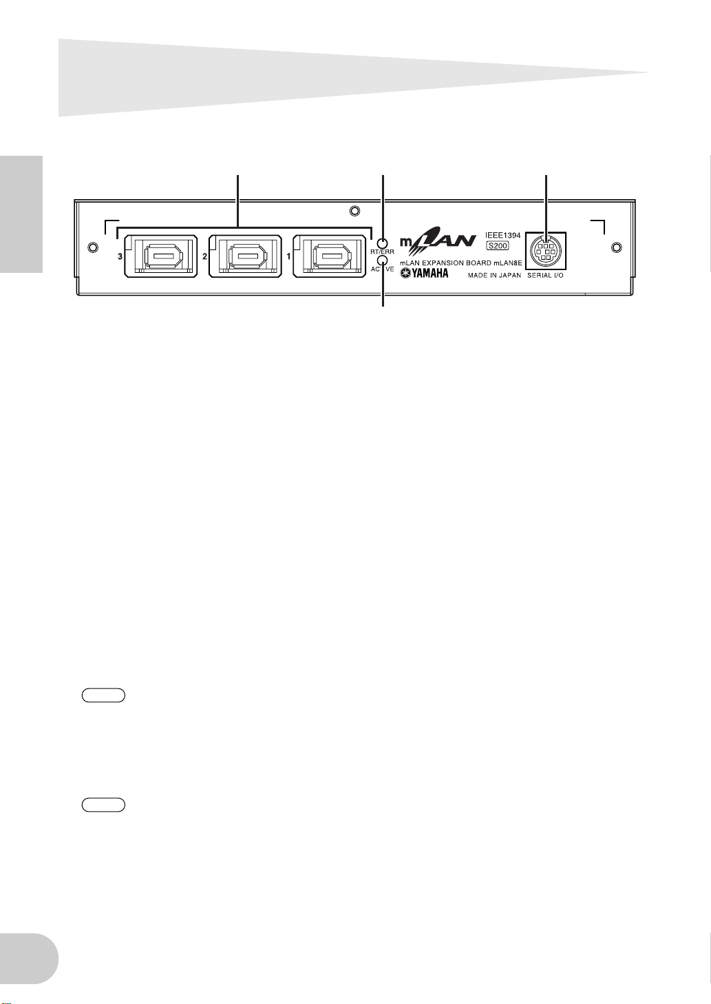
Names and Functions
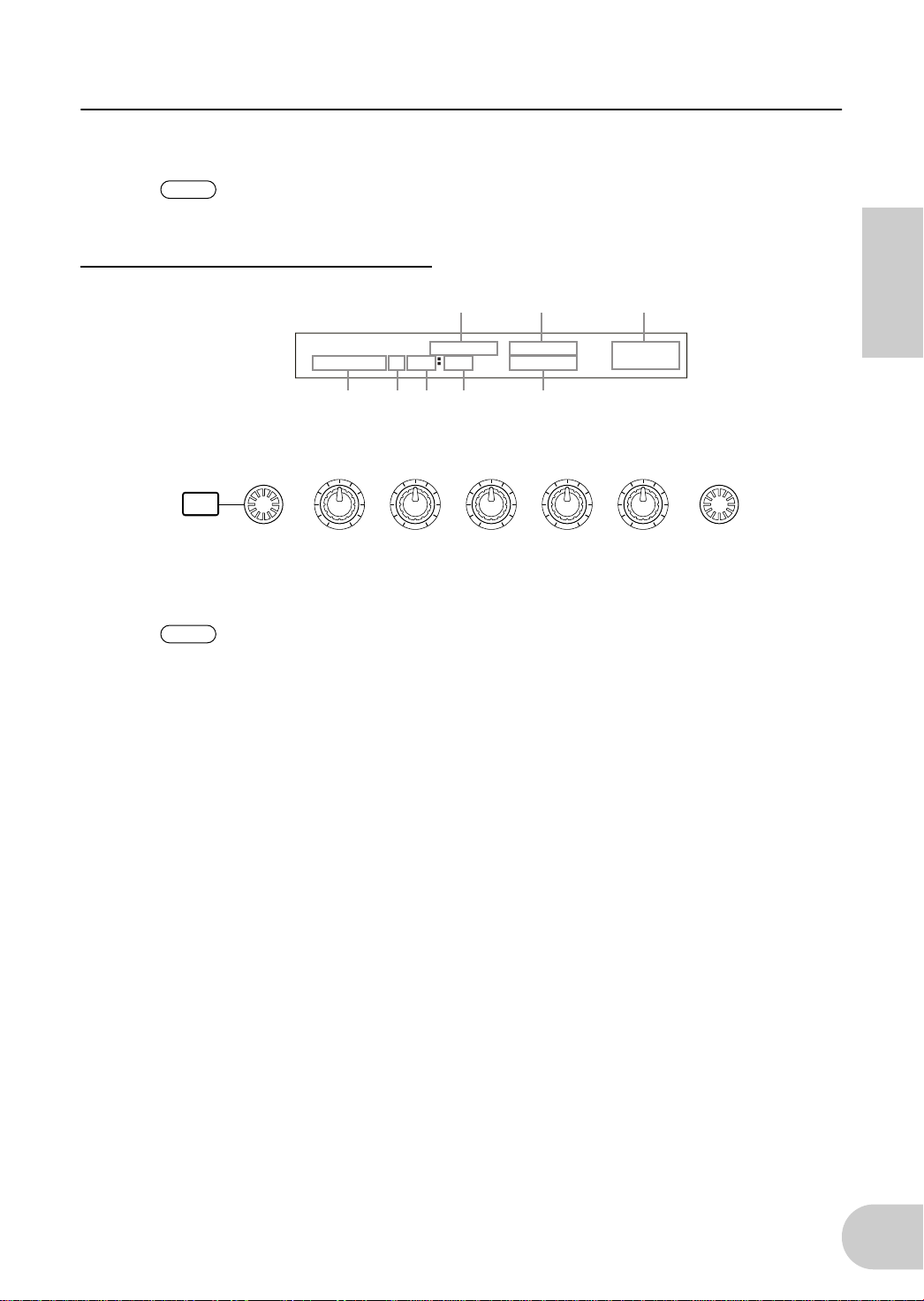
Rear Panel
English
A
SERIAL I/O jack
This jack is used to connect the mLAN8E directly to a personal computer via a serial cable. Use this
jack to connect the mLAN8E and the computer when you are using the mLAN Patchbay and mLAN
Mixer on Windows. This is not used to input or output MIDI and audio signals. Refer to page 7 for
more information on the connections.
B
mLAN (IEEE1394) jacks
These jacks are used to connect mLAN devices or IEEE1394-compatible devices via IEEE1394 standard (6-pin) cables. Each jack has an LED in the upper left corner to indicate the following statuses.
green : The mLAN8E or connected device is a “leaf” node.
off : Not connected.
red : If the cable is disconnected, the sound will be interrupted on a connected device or other
3 12
4
device.
C
RT/ERR LED
This LED indicates the following statuses.
green : The mLAN8E is a “root.”
orange : An error has occurred. (IEEE1394 bus-related)
red : An error has occurred. (Other errors)
off : Status other than above.
NOTE
D
ACTIVE LED
This LED indicates the following statuses.
blue : The relay function is active.
off : The relay function is disabled.
NOTE
Refer to “LED Messages” on page 21 for information on the error indication.
Since the mLAN8E does not function as a bus relay when the power is turned off, the active
LED also indicates whether the power to the unit is on (blue) or off.
6
Page 7
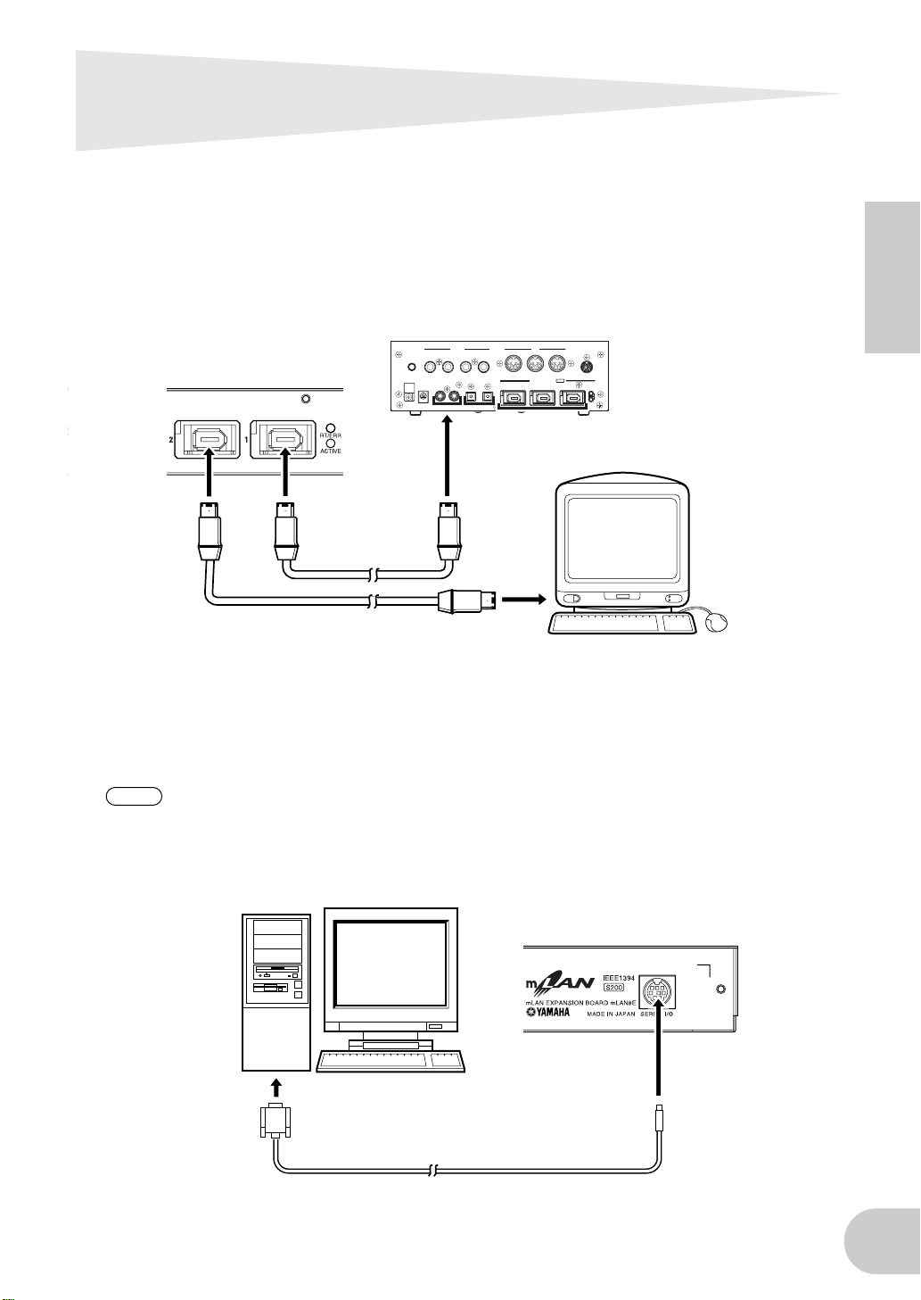
Connections
Here’s how to connect the mLAN8E to other mLAN devices or to your computer.
Connecting an mLAN (IEEE1394) device
Use an IEEE1394 standard (6-pin) cable to connect the mLAN (IEEE1394) jack on the mLAN
(IEEE1394) device to the mLAN (IEEE1394) jack on the mLAN8E. At this time, you do not have to
turn off the power to either device.
mLAN8E
mLAN (IEEE1394) device
CONTRAST ANALOG MIDI
IEEE1394
standard cable
OUT2/R OUT1/L IN2/R IN1/L
DC IN
OUT IN OUT IN
OUT-B OUT-A IN
OPTICALCOAXIAL
SERIAL I/O
mLAN IEEE1394 S200
123
RT/ERR
ACTIVE
Macintosh computer
that supports FireWire
English
IEEE1394 standard cable
Connecting a Windows computer (serial connection)
Use a serial cable to connect the computer’s RS232C jack to the mLAN8E’s SERIAL I/O jack. At this
time, make sure that the power to the computer and the device in which the mLAN8E is installed
is turned off.
NOTE
Use a standard D-SUB 9P → MINI DIN 8P cable.
Make this serial connection when using the included software on Windo ws. To use on a Macintosh, connect the mLAN8E’s mLAN jack and the Macintosh’s FireWire port using an IEEE1394
cable. (See “Connecting an mLAN device.”)
mLAN8E
computer
RS-232C
(DB9)
7
Page 8
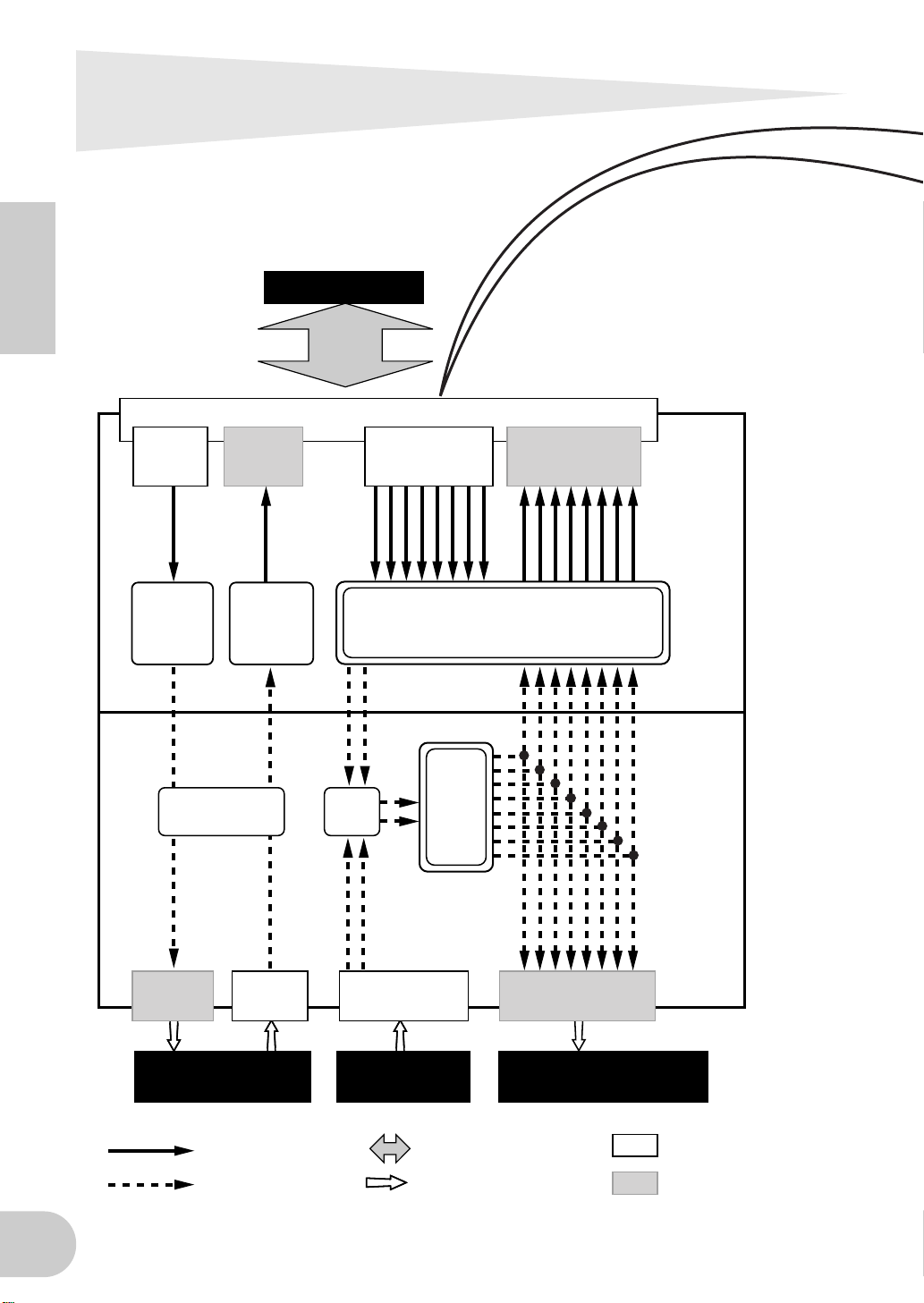
Internal Configuration of the
mLAN8E
English
mLAN device
mLAN jacks1-3
mLAN
MIDI IN
mLAN MIDI/
MIDI
conversion
MIDI transmit/
receive section
mLAN
MIDI OUT
MIDI/
mLAN MIDI
conversion
Source
select
MIDI INMIDI OUT ANALOG IN ANALOG OUT
mLAN
audio input*
2
Digital Mixer section*
Tone
generator
section
mLAN
audio output
1
mLAN8E
mLAN8E-
compatible
device
MIDI device
mLAN signals
non-mLAN signals
audio device
mLAN cables
non-mLAN cables
e.g., mixer,
powered speakers
Input
Output
8
Page 9
Internal Configuration of the mLAN8E
mLAN plugs (in Mixer mode)
mLAN output plugs (Indicated in the
“From” field in mLAN Patchbay.)
mLAN audio
Mix L (stereo mix L)
Mix R (Stereo mix R)
AUX1
AUX2
AUX3
AUX4
AUX5
AUX6
mLAN MIDI
MIDI OUT
NOTE
NOTE
In Direct mode, the number and names of plugs displayed will differ according to the
device in which the mLAN8E is installed (page 22).
There are no mLAN input plugs corresponding to the A/D INPUT of the CS6x/CS6R/S80.
mLAN input plugs (Indicated in the
“To” field in mLAN Patchbay.)
mLAN audio
CH9
CH10
CH11
CH12
CH13
CH14
CH15
CH16
mLAN MIDI
MIDI IN
The diagram on the left illustrates the entire signal flow.
The mLAN8E has 16-channel digital mixer functionality, and can mix mLAN audio signals with audio
signals produced by the device that contains the mLAN8E.
The input/output destinations of these signals and the mixer functionality can be easily controlled
from your computer by using the included mLAN Tools.
English
NOTE
*1 The included mLAN Mixer application is required in order to make digital mixer settings. For details on
the structure of the digital mixer section, refer to the block diagram of the mLAN Mixer manual.
*2 For mLAN audio inputs, you can select from any 8 channels on the bus (system).
The mLAN8E mixer section features Direct mode and Mixer mode. When the mLAN Mixer is
not being used, the unit is in Direct mode, in which signals are input and output directly. When
mLAN Mixer is being used, the unit enters Mixer mode. The default setting (when you turn on
the power to the unit) is Direct mode. If you turn the power to the device off, then on while
mLAN Mixer is running, restart mLAN Mixer.
9
Page 10
Settings on the device in which
NOTE
NOTE
the mLAN8E is installed
For the A5000/A4000
English
If the mLAN8E is installed in the A5000/A4000, you will be able to make mLAN-related settings.
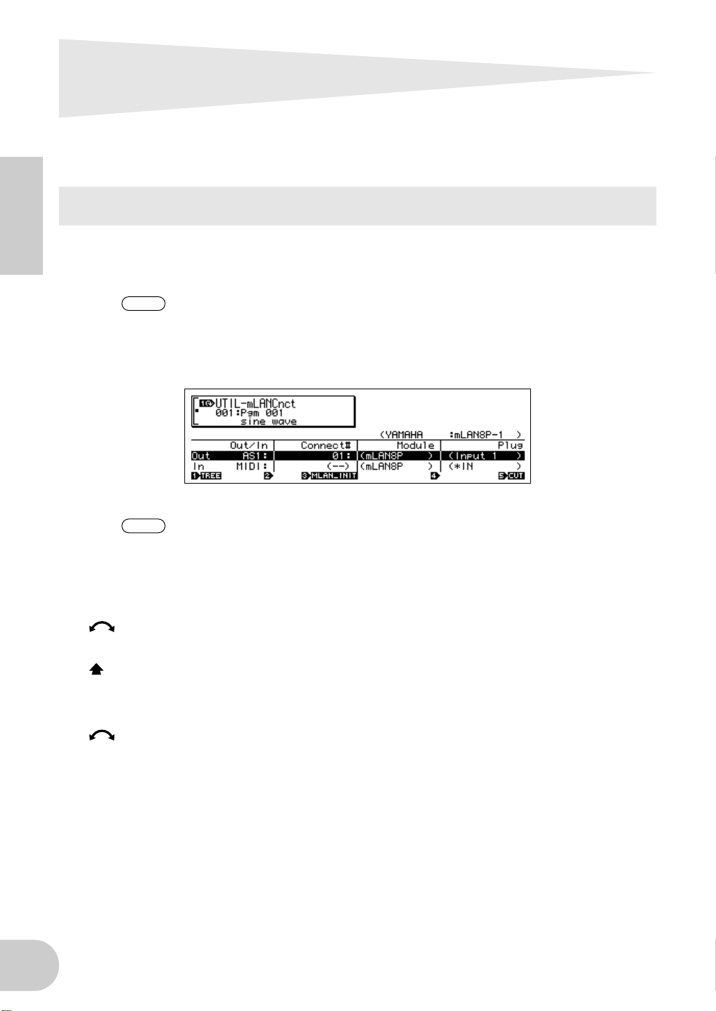
mLAN settings are made in Utility mode.
In order to use mLAN, you must first access the mLAN Configuration page
and set MIDI Input to a setting other than MIDI IN.
mLAN Cnct (mLAN connections)
mLAN connections tone generators are saved in the mLAN8E. They cannot
be saved on disk.
Cursor 1 Out (output)
Knob 1
■
[ turn] Move cursor / switch pages
Move the cursor or switch pages.
[ press] Tree View
Access the Tree View screen.
Knob 2
■
[ turn] Out (select output plug)
Select the mLAN plug of the mLAN8E that will be the output source.
❑
Setting:
AS (assignable) 1~6, DIG-L, DIG-R, MIDI
10
Page 11
Settings on the device in which the mLAN8E is installed
NOTE
NOTE
NOTE
NOTE
■
Knob 3
[ turn] Connect# (select connection number of the connected mLAN device)
Select the connection number of the connected mLAN device. In the case of numbers for
which a connection has already been made, the module name and plug name will be displayed in parentheses. If there are fewer than 62 connections, you can select “New” and create a new connection (mLAN input plug).
❑
Setting:
[ press] mLAN_INIT (mLAN initialize)
Initialize mLAN-related settings. This will be executed after you reply to a confirmation dialog
box.
All connection settings will be set to “---”. The Word Clock Mode will be “Auto.”
Knob 4
■
[ turn] Module (select connected module)
Select an mLAN device on the mLAN bus (system). When you select a valid mLAN device, the
top line will show the vendor name and the Nickname.
1~62, New
The Nickname settings will not be initialized.
Settings cannot be modified for the connection number of an already-established connection.
English
Knob 5
■
[ turn] Plug (select connected mLAN plug)
Select the mLAN input plug of the connected mLAN device.
The connection is executed by CONNECT (press knob 5). If after making
your selection, you change pages, move the cursor, or change the Out or
Connect# settings without executing CONNECT, the selected value will be
cleared.
If there are no plugs that can be selected, this will be displayed as “---.”
[ press] CONNECT
Connect to the mLAN input plug of the selected mLAN device.
If the connection number is “New,” this function will appear if you have selected a module
name or plug name that can be connected.
[ press] CUT (disconnect)
Break the selected connection.
This function will appear if you have selected an already-connected module name / plug
name.
11
Page 12
Settings on the device in which the mLAN8E is installed
NOTE
NOTE
NOTE
Cursor 2 In (input)
■
Knob 1
[ turn] Move cursor / switch pages
Move the cursor or switch pages.
[ press] Tree View
Access the Tree View screen.
Knob 2
■
English
[ turn] In (select input plug)
Select the mLAN8E mLAN plug that will input the signal. If a connection has already been
made, the module name and plug name will be displayed in parentheses.
❑
Setting:
■
Knob 3
Display only
If unconnected, this will indicate “New.”
[ press] mLAN_INIT (mLAN initialize)
Initialize mLAN-related settings. This will be executed after you reply to a confirmation dialog
box.
All connection settings will be set to “---”. The Word Clock Mode will be “Auto.”
AD-L, AD-R, MIDI
The Nickname settings will not be initialized.
Knob 4
■
[ turn] Select connected module
Select an mLAN device on the mLAN bus (system). When you select a valid mLAN device, the
top line will show the vendor name and the Nickname.
■
Knob 5
[ turn] Select connected mLAN plug
Select an mLAN output plug on the connected mLAN device.
The connection is executed by CONNECT (press knob 5). If after making
your selection, you change pages, move the cursor, or change the Out or
Connect# settings without executing CONNECT, the selected value will be
cleared.
If there are no plugs that can be selected, this will be displayed as “---.”
[ press] CONNECT
Connect to the mLAN output plug of the selected mLAN device.
If the node number is “New,” this function will appear if you have selected a module name or
plug name that can be connected.
[ press] CUT (disconnect)
Break the selected connection.
This function will appear if you have selected an already-connected module name or plug
name.
12
Page 13
Settings on the device in which the mLAN8E is installed
NOTE
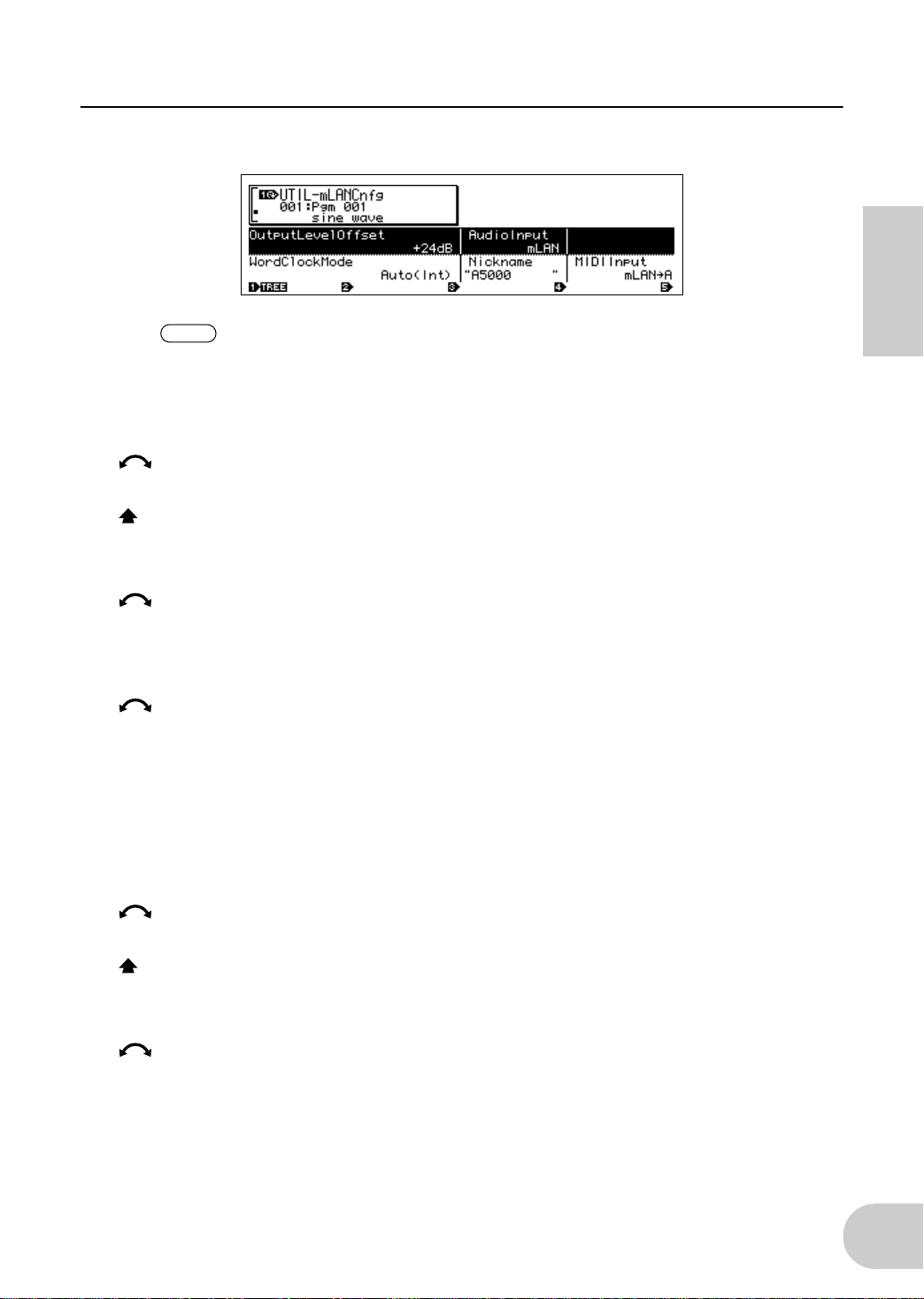
mLAN Cnfg (mLAN configuration)
Output Level Offset, Word Clock Mode, and Nickname settings are saved in
the mLAN8E. They cannot be saved on disk.
Cursor
■
■
■
1
Knob 1
[ turn] Move cursor / switch pages
Move the cursor or switch pages.
[ press] Tree View
Access the Tree View screen.
Knob 2
[ turn] Output Level Offset
Specify the output volume (offset value) for all mLAN audio outputs.
❑
Setting:
Knob 4
[ turn] Audio Input (audio input select)
Select the audio input source.
❑
Setting
ADIn: Use two analog audio channels from the INPUT jacks of the A5000/A4000.
mLAN: Use two mLAN audio channels. The audio signals from the INPUT jacks of the A5000/
+0 dB ~ +24 dB
A4000 will not be input.
English
Cursor
■
■
2
Knob 1
[ turn] Move cursor / switch pages
Move the cursor or switch pages.
[ press] Tree View
Access the Tree View screen.
Knob 3
[ turn] Word Clock Mode
Specify the word clock.
❑
Setting
Auto: The word clock of the audio output will automatically synchronize to an 44.1 kHz external
device. The A5000/A4000 may function as the master in some cases, or as the slave in
other cases.
Group1Master (44.1 kHz): The A5000/A4000 will function as a 44.1 kHz master device.
13
Page 14
Settings on the device in which the mLAN8E is installed
NOTE
NOTE
Before the Word Clock Mode is selected or after SET is executed, this will indicate the current
Word Clock Mode. The display has the following significance.
•
Auto(Int): Operating in Auto Mode on the internal clock
•
Auto(Ext): Operating in Auto Mode as a slave
•
---(Int): Operating in Manual Mode on the internal clock
•
---(Ext): Operating in Manual mode as a slave
English
[ press] SET (finalize word clock)
Finalize the selected Word Clock Mode setting.
■
Knob 4
Nickname (display only)
Displays the Nickname of the A5000/A4000.
[ press] Rename
Set the Nickname.
Knob 5
■
[ turn] MIDI Input (MIDI Input selection)
❑
Regardless of this setting, the same MIDI output data is sent from both MIDI
OUT and mLAN MIDI.
Regardless of this setting, the MIDI THRU connector will re-transmit the data
that was input to MIDI IN.
Setting
MIDI IN: MIDI messages input from the MIDI IN connectors will play the A5000/A4000; mLAN will
not be used.
mLAN->A: MIDI messages from the mLAN MIDI input will be sent to the MIDI IN-A por t. MIDI mes-
sages from the rear panel MIDI IN-A connector will not be input (A5000 only).
mLAN->B: MIDI messages from the mLAN MIDI input will be sent to the MIDI IN-B por t. MIDI mes-
sages from the rear panel MIDI IN-B connector will not be input (A5000 only).
mLAN: MIDI messages from the mLAN MIDI input will be input to the MIDI IN por t. MIDI mes-
sages from the rear panel MIDI IN connector will not be input (A4000 only).
14
Page 15
Settings on the device in which the mLAN8E is installed
For the CS6x/CS6R/S80
If the mLAN8E is installed in the CS6x/CS6R/S80, you will be able to make mLAN-related settings.
mLAN settings are made mainly in Utility mode.
MIDI settings
1
Press the [UTILITY] key to enter Utility mode.
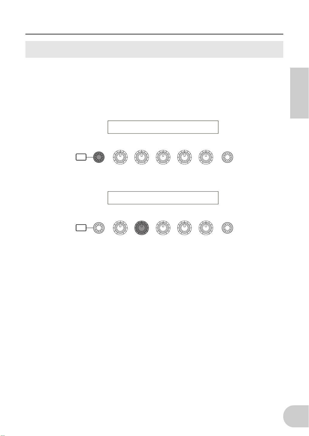
2
Turn the [PAGE] knob to access the “MIDI Other” page.
MIDI Other) In ThruPort Sync SeqCtrl
Sys MIDI 1 int on
English
SHIFT P A GE
3
Use knob [B] to set “In” to “mLAN.”
SHIFT P A GE
/
ELEMENT
PART
MIDI Other) In ThruPort Sync SeqCtrl
Sys mLAN 1 int on
/
ELEMENT
PART
DATAABC1 2
DATAABC1 2
15
Page 16
Settings on the device in which the mLAN8E is installed
NOTE
NOTE
NOTE
MIDI Other
An CS6x/CS6R/S80 in which the mLAN8E is installed will have the following additional functions.
MIDI Other) In ThruPort Sync SeqCtrl
Sys mLAN 1 int on
■
In (MIDI Input)
English
Select whether to use the MIDI connector or the mLAN connector as the input route for MIDI
messages. If you select “mLAN,” the HOST SELECT switch will have no effect, and MIDI messages from devices connected to the TO HOST connector or MIDI IN connector will not be
input.
❑
Setting:
MIDI, mLAN
Regardless of this setting, MIDI OUT messages will be output both from the
MIDI OUT connector and the mLAN connector.
If you select mLAN, MIDI OUT messages will not be output from TO HOST.
If you select mLAN, the ThruPort setting will have no effect.
■
Sync (when the above MIDI Input = mLAN)
When playing in synchronization with an external device, specify whether the CS6x/CS6R/S80
will operate using its own internal clock or the MIDI Clock received via the mLAN connector. If
you select “Int (internal),” the CS6x/CS6R/S80 will operate using its own internal clock. Select
this when using the CS6x/CS6R/S80 by itself or as the master of a synchronized performance
using MIDI Clock. If you select “MIDI,” the CS6x/CS6R/S80 will operate according to the
MIDI Clock received via the mLAN connector. Select this when using the CS6x/CS6R/S80 as a
slave of a synchronized performance using MIDI Clock.
❑
Setting:
■
SeqCtrl (Sequence Control) (when the above MIDI Input = mLAN)
MIDI, int (internal)
Specify whether or not you wish to transmit and receive the mLAN MIDI messages Start, Stop,
and Continue. This is also a switch for outputting MIDI Clock from mLAN MIDI output.
❑
Setting:
off (don’t transmit or receive), on (transmit and receive)
16
Page 17
Settings on the device in which the mLAN8E is installed
NOTE
NOTE
mLAN Connection, Word Clock, and Nickname settings
The method of entering each page is the same as for MIDI Setting. In Utility
mode, turn the [PAGE] knob to display the desired page. (Page 15)
mLAN Connect (mLAN connection)
3
mLAN Connect)YAMAHA :Vivien [ENTER]
MIDI OUT->New:S80 MIDI-IN toCnct
6
1 2 7
SHIFT PAGE
PART
/
ELEMENT
A
mLAN plug of the mLAN8E
The number of plugs and their names will differ depending on the device in
which the mLAN8E is installed.
B
This indicates an input setting (<-) or output setting (->). In the example
5
4 8
DATAABC1 2
shown above, the MIDI OUT plug of the mLAN8E is being connected to an
external S80 (Nickname=Vivien).
C
Vendor name of connected device
D
Nickname of connected device
English
E
Connection number of connected device
F
Module name of connected device
G
mLAN plug name of connected device
H
Connect/disconnect
[ENTER] toCnct ... press the [ENTER] key to connect
[ENTER] toCut ... press the [ENTER] key to disconnect
17
Page 18
Settings on the device in which the mLAN8E is installed
NOTE
NOTE
NOTE
NOTE
NOTE
•
mLAN8E output settings
(1) Turn knob [A] to select the output source mLAN plug of the mLAN8E.
You can turn knob [B] to check up to 62 Connection numbers for destination
mLAN devices.
If no previously-specified connection destinations are found, the display will
indicate “*****”.
English
If the connection has not been established, “New” will be displayed above
knob [B], and “[ENTER] toCnct” will be displayed above knob [2].
If the connection has already been established, the current connection destination will be displayed. Also, “[ENTER] To Cut” will be displayed above
knob [2]. In this case, pressing [ENTER] will cut the connection.
(2) Turn knob [C] to select an mLAN device on the mLAN bus (system). The upper line will show
the vendor name, and the lower line will show the module name.
(3) Turn knob [1] to select the mLAN input plug of the connected mLAN device, and press the
[ENTER] key. The connection will be executed, and the “New” indication will change to a
number.
To change an existing connection, you must first break the connection and
then specify a new connection.
If the names (vendor name, module name, mLAN plug name) of the connected device exceed eight characters, only the first eight characters will be
displayed.
18
Page 19
Settings on the device in which the mLAN8E is installed
NOTE
NOTE
NOTE
NOTE
NOTE
NOTE
•
mLAN8E input settings
An mLAN input plug of the mLAN8E can have only one connection.
(1) Turn knob [A] to select the mLAN8E mLAN plug that will input the signal. The module name
and plug name for the destination device will be displayed as “-----”.
If a connection has already been established, the current connection destination will be displayed. Also, the display will indicate “[ENTER] To Cut”
above knob 2. In this case, press [ENTER] to break that connection.
(2) Turn knob [C] to select an mLAN device on the mLAN bus (system). The upper line will show
the vendor name, and the lower line will light the module name.
(3) Turn knob [1] to select an mLAN input plug on the destination mLAN device, and press
[ENTER] to execute the connection.
To change an existing connection, you must first break the connection and
then specify a new connection.
If the names (vendor name, module name, mLAN plug name) of the connected device exceed eight characters, only the first eight characters will be
displayed.
English
mLAN connections tone generators are saved in the mLAN8E. They cannot
be saved on a memory card.
mLAN W
ord Clock
Select the Word Clock.
mLAN WordClock) Mode [ENTER]
Sys Group1Master(44.1kHz) to Set
Mode
■
Select whether the CS6x/CS6R/S80 will function as the Word Clock Master (Group 1 Master)
of the connected mLAN Audio network, or whether the slave/master setting will be selected
automatically (auto). When you select the Mode and press [ENTER], a confirmation screen will
appear. To execute the setting press [YES]. To cancel press [NO]. When the setting has been
finalized, the display will indicate “(int)” or “(ext=********)” at the right of Mode. “(int)” indicates that the CS6x/CS6R/S80 in which the mLAN8E is installed is acting as the word clock
master. “(ext=********)” indicates that it is acting as the slave of an external module named
“********”.
❑
Setting:
auto (44.1 kHz), Group1Master (44.1 kHz)
This setting is stored in the mLAN8E. It cannot be saved on a memory card.
19
Page 20

Settings on the device in which the mLAN8E is installed
NOTE
mLAN initialize
This initializes the mLAN connection and word clock settings of the mLAN8E installed in the
CS6x/CS6R/S80. When you press [ENTER], a confirmation screen will appear. Press [YES] to exe-
cute the initialization, or press [NO] to cancel.
mLAN Initialize) [ENTER]
Sys to Init
English
The Nickname settings will not be initialized.
mLAN Nickname
Specify the nickname of the CS6x/CS6R/S80 in which the mLAN8E is installed. The input procedure is the same as when inputting a CS6x/CS6R/S80 voice name.
After inputting the name, press [ENTER] to finalize it.
mLAN Nickname) a-Z 0-? Cursor
Sys [Vivien ]
Other mLAN-related settings
•
Voice mode
For OSC Pan (oscillator pan) Output, you will be able to specify ind3~ind6.
•
Performance mode
For LYR Out (layer out) Output, you will be able to specify ind3~ind6.
•
Phrase Clip mode (CS6x/CS6R)
For OSC Pan (oscillator pan) Output, you will be able to specify ind3--ind6.
20
Page 21

LED Messages
LED messages
Function Status
mLAN1–3
RT/ERR Indicates root and error.
ACTIVE Indicates the status of the relay function. Blue ... The relay function is enabled.
Indicates if sound from sources other than the
device being disconnected is interrupted.
Error messages
Red ... Sound is interrupted.
Green ... Sound is not interrupted. (leaf node)
Red/orange ... An error has occurred.
Green ... The mLAN8E is a “root.”
English
32 1 RT
red orange
red orange
red red orange
green
green
red red
orange The number of hops exceeds 16. Check the number of hops.
orange The power to the bus is insufficient.
red red MIDI IN transfer rate is not correct. Check the MIDI transfer rate setting.
red
Cause Action
The topology of the connected
devices creates a loop.
Cycle Start Packet is not transmitted
to the bus. (Audio/MIDI data cannot
be transmitted.)
A malfunctioning device exists on the
bus.
Data transmission exceeds the MIDI
transfer rate.
The sound is interrupted for some reason, or the devices are not syncing.
Check to see if any part of the connection creates a loop.
Remove the malfunctioning device.
Remove the malfunctioning device.
Add a power provider to the bus, or
remove a power consumer from the
bus.
Check to see if the transmitting
device is operating properly.
Check the word clock setting on the
mLAN8E and the source.
21
Page 22

Specifications
mLAN
Sampling rate
Functions
English
Jacks
mLAN plugs
IEEE1394 High Performance Serial Bus
Data Rate S200, Isochronous Resource Manager capable, Bus Manager capa-
ble, Connection Manager
Conforms to IEC61883-6 Audio and Music Protocol
Digital Audio 8in/8out, MIDI 1in/1out
44.1kHz
Direct Mode
Input: 2 (max), Output: 8 (max)
Mixer Mode
Input: 16 (max) Link, Gain, ATT, Phase, EQ (4Band)*, Dynamics*, AUX Send
(x6), Pre/Post (x6), Channel on/off, Meter, Pan, Fader
Output: 8 (max) Level, Balance, AUX Link, AUX Master (x6)
* Up to eight channels
mLAN IEEE1394 (1, 2, 3), SERIAL I/O
Direct mode
A5000/A4000 AS1–6 OUT, DG-L OUT, DG-R OUT, AD-L IN, AD-R IN,
MIDI OUT, MIDI IN
CS6x/CS6R/S80 IND1–6 OUT, L OUT, R OUT, MIDI OUT, MIDI IN
Mixer mode Mix L, Mix R, AUX1–6, CH9–16, MIDI OUT, MIDI IN
NOTE
For more information, refer to “mLAN plugs (in Mixer mode)”
on page 9.
Display
Power consumption
Specifications and descriptions in this owner’s manual are for information purposes only. Yamaha Corp. reserves the right
to change or modify products or specifications at any time without prior notice.Since specifications, equipment or options
may not be the same in every locale, please check with your Yamaha dealer.
Rear panel: mLAN 1/2/3 LED, ACTIVE LED, RT (Root)/ERR (Error) LED
4 W
22
Page 23

Inhalt
Einführung...................................................................................... 4
Installation der mLAN8E ................................................................ 4
Lieferumfang .................................................................................. 4
Leistungsmerkmale ........................................................................5
Bezeichnungen und Funktionen.................................................... 6
Anschlüsse ...................................................................................... 7
Interne Konfiguration des mLAN8E............................................... 8
Einstellungen am Gerät, in dem die mLAN8E eingebaut ist....... 10
Beim A5000/A4000 ............................................................................10
Beim CS6x/CS6R/S80.........................................................................15
Meldungen der LED-Anzeigen..................................................... 21
Technische Daten......................................................................... 22
Deutsch
3
Page 24

Einführung
Vielen Dank für den Kauf der Yamaha mLAN8E. mLAN ist ein digitales Netzwerk für Musik und
basiert auf dem seriellen Hochleistungsbus IEEE 1394. Mit mLAN können Sie sehr einfach
anspruchsvolle Netzwerke für Audio-und MIDI-Signale aufbauen und verwalten, ohne immer
wieder einzelne Kabelverbindungen herstellen oder lösen zu müssen.
Die mLAN8E bietet Mischpultfunktionen und stellt eine leistungsfähige Erweiterung Ihres
Musikproduktionssystems dar.
Um alle Vorteile der Funktionen des mLAN8E nutzen zu können, lesen Sie diese Anleitung bitte
genau durch. Bewahren Sie die Anleitung zum späteren Nachschlagen bitte gut auf.
Installation der mLAN8E
Die Installation der mLAN8E muß durch qualifiziertes Yamaha-Fachpersonal oder einen der
Yamaha-Händler durch geführt werden, der am Ende der Anleitung des Gerätes aufgeführt ist,
in dem die mLAN8E installiert werden soll.
Deutsch
Lieferumfang
•
mLAN8E-Karte
•
mLAN-Tools (CD-ROM)
•
IEEE1394-Kabel (4,5m)
•
26-poliges Flachkabel (um mLAN8E und mLAN8E-kompatible Geräte miteinander zu verbinden)
•
Streifen (zum Befestigen der Kabel)
•
Bedienungsanleitung (dieses Handbuch)
•
mLAN-Leitfaden
•
Installationshandbuch für mLAN-Tools
Die beiliegende CD-ROM
Die mitgelieferte CD-ROM enthält Software, die für die Verwendung der mLAN8E nützlich sein
kann. Die Software enthält „mLAN Patchbay“, womit Sie das Routing der Audio- und MIDISignale zwischen elektronischen Musikinstrumenten, die an der mLAN8E angeschlossen sind,
von Ihrem Computer aus steuern können, sowie „mLAN Mixer“, womit Sie die Funktionen des
Mixers und des Dynamik-Prozessors des mLAN8E von Ihrem Computer aus steuern können.
Weitere Informationen hierzu finden Sie in der „Installationsanleitung für mLAN-Tools“.
Yamaha haftet nicht für Schäden, die auf eine nicht bestimmungsgemäße Verwendung
oder auf Änderungen am Instrument zurückzuführen sind, oder für den Verlust oder die
Zerstörung von Daten.
Die Abbildungen und LCD-Anzeigen in dieser Bedienungsanleitung dienen lediglich der Illustration und
können vom tatsächlichen Erscheinungsbild auf Ihrem Gerät abweichen.
Die in dieser Bedienungsanleitung erwähnten Firmen- und Produktnamen sind Warenzeichen bzw.
eingetragene Warenzeichen der jeweiligen Firmen.
4
Page 25

Leistungsmerkmale
■
Schnelle Datenübertragung über mLAN
mLAN ist ein digitales Netzwerk für Musik. Es verwendet den seriellen Hochleistungs-Bus IEEE
1394 und ermöglicht den Aufbau von Systemen, die noch komplexer und dabei einfacher zu
handhaben sind als je zuvor. Für Einzelheiten zu mLAN lesen Sie bitte das gesonderte „mLAN
Guidebook“.
■
16-Kanal-Mischpult-Funktion
Ein 16-kanaliges Digitalmischpult ist eingebaut.
■
Eingebaute Klangregelung / Dynamikprozessor
Ein vierbandiger Equalizer und ein Dynamikprozessor bieten eine ausgefeilte Klangkontrolle.
*
*
Deutsch
* Die Einstellungen des Mischpultes (Mixer), der Klangregelung (Equalizer) und des
Dynamikprozessors werden mit Hilfe der mitgelieferten Software „mLAN Mixer“
vorgenommen. Einzelheiten hierzu finden Sie im mLAN-Driver-Handbuch (im PDF-Format).
5
Page 26

Bezeichnungen und Funktionen
Rückseite
A
SERIAL I/O-Buchse
Über diese Buchse können Sie die mLAN8E über ein serielles Kabel direkt mit einem PC verbinden.
Deutsch
Schließen Sie die mLAN8E hierüber an einen Computer an, wenn Sie mLAN-Patchbay und mLANMixer unter Windows verwenden. Dieser Anschluß dient nicht zum Senden und Empfangen von
MIDI- und Audiosignalen. Weitere Informationen zu den Verbindungen finden Sie auf Seite 7.
B
mLAN-(IEEE1394)-Buchsen
An diesen Buchsen können Sie mLAN-Geräte oder IEEE1394-kompatible Geräte über 6-polige Kabel
nach IEEE1394-Standard anschließen. Jede Buchse besitzt in der oberen linken Ecke eine LEDAnzeige, an der die folgenden Statusangaben abgelesen werden können.
grün : Die mLAN8E oder das angeschlossene Gerät ist ein „Zweigknoten”.
aus : Nicht angeschlossen.
rot : Durch Abziehen des angeschlossenen Geräts wird die Klangwiedergabe von anderen
3 12
4
Geräten unterbrochen.
C
RT/ERR-LED
An dieser LED-Anzeige lassen sich die folgenden Statusangaben ablesen:
grün : Die mLAN8E ist ein „Stamm“.
orange : Ein Fehler ist aufgetreten. (In Bezug auf den IEEE1394-Bus)
rot : Ein Fehler ist aufgetreten. (Andere Fehler)
aus : Anderer Status als die zuvor genannten.
HINWEIS
D
ACTIVE-LED
An dieser LED-Anzeige lassen sich die folgenden Statusangaben ablesen:
blau : Die Weiterleitungsfunktion ist aktiviert.
aus : Die Weiterleitungsfunktion ist deaktiviert.
HINWEIS
Informationen zur Fehleranzeige finden Sie unter „LED-Meldungen“ auf Seite 21.
Da die mLAN8E im ausgeschalteten Zustand nicht als Bus-Relay funktioniert (d. h. keine
Signale weiterleitet), zeigt die ACTIVE-LED auch an, ob die Einheit eingeschaltet (blau) oder
ausgeschaltet ist.
6
Page 27

Anschlüsse
Hier erfahren Sie, wie Sie den mLAN8E an andere mLAN-Geräte oder an Ihren Computer
anschließen können.
Anschließen eines mLAN-(IEEE1394)-Geräts
Verbinden Sie mit einem als Zubehör erhältlichen, 6-poligen Kabel nach IEEE1394-Standard die
mLAN-(IEEE1394)-Buchse des mLAN-(IEEE1394)-Geräts mit der mLAN-(IEEE1394)-Buchse der
mLAN8E. Dazu muß keines der Geräte ausgeschaltet werden.
mLAN8E
CONTRAST ANALOG MIDI
IEEE1394-
Standardkabel
mLAN-(IEEE1394)-Gerät
OUT2/R OUT1/L IN2/R IN1/L
DC IN
OUT IN OUT IN
OUT-B OUT-A IN
OPTICALCOAXIAL
SERIAL I/O
mLAN IEEE1394 S200
123
RT/ERR
ACTIVE
Macintosh-Computer
mit FireWire
Deutsch
IEEE1394-Standardkabel
Anschließen eines Windows-Computers (serielle Verbindung)
Schließen Sie über serielles Kabel die RS232C-Buchse des Computers an der SERIAL I/O-Buchse
der mLAN8E an. Stellen Sie dazu sicher, daß Computer und das Gerät, in dem die mLAN8E
installiert ist, ausgeschaltet sind.
HINWEIS
Verwenden Sie ein 9-poliges Standard-D-SUB → 8-poliges Mini-DIN-Kabel.
Stellen Sie diese serielle Verbindung her, w enn Sie die mitgelief erte Software unter Windows
benutzen. Um die Software auf einem Macintosh-Rechner zu verwenden, verbinden Sie die
mLAN-Buchse der mLAN8E über ein IEEE1394-Kabel mit der FireWire-Schnittstelle des
Macintosh. (Lesen Sie dazu „Anschließen eines mLAN-Geräts“.)
mLAN8E
Computer
RS-232C
(DB9)
7
Page 28

Interne Konfiguration der
mLAN8E
mLAN-Gerät
mLAN-Buchsen 1-3
Deutsch
mLAN-
MIDI IN
mLAN-MIDI/
MIDI-
Konvertierung
MIDI-Übertragung
Empfang
mLAN-
MIDI OUT
MIDI/
mLAN-MIDI-
Konvertierung
Source-
Auswahl
MIDI INMIDI OUT ANALOG IN ANALOG OUT
mLAN-
Audioeingang*
Digitalmischpult*
Ton-
generator
2
MLAN-
Audio-Ausgang
1
mLAN8E
mLAN8E
-kompatibles
Gerät
MIDI-Gerät
mLAN-Signale
Andere Signale
(nicht mLAN)
Audio-Gerät
mLAN-Kabel
Andere Kabel
(nicht mLAN)
z.B., Aktiv-
lautsprecher
Eingang
Ausgang
8
Page 29

Interne Konfiguration der mLAN8E
mLAN-Stecker (im Mixer-Modus)
mLAN-Ausgangsstecker (angezeigt im
„From“-Feld von mLAN Patchbay).
mLAN-Audio
Mix L (stereo mix L)
Mix R (Stereo mix R)
AUX1
AUX2
AUX3
AUX4
AUX5
AUX6
mLAN-MIDI
MIDI OUT
HINWEIS
HINWEIS
Im Direkt-Modus unterscheiden sich Anzahl und Namen der Stecker je nach dem
Gerät, in dem das mLAN8E installiert ist (Seite 22).
Es gibt keine mLAN-Eingangsstecker passend für die A/D-Eingänge des
CS6x/CS6R/S80.
mLAN-Eingangsstecker (angezeigt
im „To“-Feld von mLAN Patchbay).
mLAN audio
CH9
CH10
CH11
CH12
CH13
CH14
CH15
CH16
mLAN-MIDI
MIDI IN
Das Diagramm links zeigt den gesamten Signalfluß.
Die mLAN8E besitzt die Funktionen eines eingebauten, 16-kanaligen Digitalmischpultes und kann so
mLAN-Audiosignale mit den Audiosignalen desjenigen Gerätes mischen, in dem die mLAN8E
eingebaut ist.
Die Routings der Ein- und Ausgänge sowie die Mischpultfunktionen können sehr einfach mit den
mitgelieferten mLAN Tools über Ihren Computer gesteuert werden.
Deutsch
HINWEIS
*1 Die beiliegende Anwendung „mLAN Mixer“ ist erforderlich für die Einstellung des Digitalmischpults.
Weitere Informationen zur Struktur des Digitalmischpult-Blocks finden Sie im Blockschaltplan im mLANMixer-Handbuch.
*2 Für den mLAN-Audioeingang können Sie beliebig aus 8 Kanälen des Bus (Systems) auswählen.
Der Mischpult-Block der mLAN8E befindet sich entweder im Direkt-Modus oder im MixerModus. Wenn mLAN Mixer nicht verwendet wird, ist die Einheit im Direkt-Modus, in dem einund ausgehende Signale direkt weitergeleitet werden. Wird mLAN Mixer verwendet,
wechselt die Einheit in den Mixer-Modus. Die Standardeinstellung (beim Einschalten des
Geräts) ist der Direkt-Modus. Wenn Sie das Gerät aus- und wieder einschalten, während
mLAN Mixer läuft, sollten Sie mLAN Mixer neu starten.
9
Page 30

Einstellungen am Gerät, in dem die mLAN8E eingebaut ist
Beim A5000/A4000
Wenn die mLAN8E im A5000/A4000 eingebaut ist, können Sie mLAN-bezogene Einstellungen
vornehmen. mLAN-Einstellungen erfolgen im Utility-Modus.
HINWEIS
Um mLAN benutzen zu können, müssen Sie zuerst die Seite „mLAN
Configuration“ aufrufen und den MIDI-Eingang auf einen anderen Wert als
MIDI IN einstellen.
mLAN Cnct (mLAN-Verbindungen)
Deutsch
HINWEIS
Cursor 1 Out (Ausgang)
■
Knopf 1
[ Drehen] Cursor bewegen / Seiten umschalten
Bewegt den Cursor oder schaltet Seiten um.
[ Drücken] Tree View (Baumdarstellung)
Anzeige mit der Baumdarstellung aufrufen.
mLAN-Verbindungen zu Tongeneratoren werden in der mLAN8E
gespeichert. Sie können nicht auf Diskette gespeichert werden.
10
Knopf 2
■
[ Drehen] Out (Ausgangsstecker auswählen)
Wählen Sie den mLAN-Stecker der mLAN8E, der das Ausgangssignal führen soll.
❑
Einstellungen:
AS (zuweisbar) 1~6, DIG-L, DIG-R, MIDI
Page 31

Einstellungen an dem Gerät, in dem die mLAN8E eingebaut ist
■
Knopf 3
[ Drehen] Connect# (Anschlußnummer des ausgewählten mLAN-Gerätes einstellen)
Hier stellen Sie die Anschlußnummer des ausgewählten mLAN-Gerätes ein. Bei Nummern, die
bereits vergeben sind, erscheinen Modul- und Steckernamen in Klammern. Wenn weniger als
62 Verbindungen bestehen, können Sie den Eintrag „New“ wählen und eine neue Verbindung
erzeugen (mLAN-Eingangsstecker).
❑
Einstellungen:
[ Drücken] mLAN_INIT (mLAN initialisieren)
Initialisiert mLAN-bezogene Einstellungen. Diese Funktion wird ausgeführt, nachdem Sie
einen Dialog bestätigt haben.
Alle Verbindungseinstellungen werden auf „---“ eingestellt. Der Word-Clock-Modus wird auf
„Auto“ eingestellt.
1~62, New
■
HINWEIS
Knopf 4
Die Nickname-Einstellungen werden nicht initialisiert.
[ Drehen] Module (angeschlossenes Modul auswählen)
Wählt ein mLAN-Gerät auf dem mLAN-Bus (System) aus. Wenn Sie ein gültiges mLAN-Gerät
auswählen, wird in der oberen Zeile der Herstellername und der „Spitzname“ (Nickname)
angezeigt.
■
HINWEIS
Knopf 5
Die Einstellungen bereits aufgebauter Verbindungen können nicht
geändert werden.
[ Drehen] Plug (angeschlossenen mLAN-Stecker auswählen)
Wählt den mLAN-Eingangsstecker des angeschlossenen mLAN-Gerätes.
HINWEIS
HINWEIS
Die Verbindung wird durch den CONNECT-Befehl (Knopf 5 drücken)
hergestellt. Wenn Sie nach der Auswahl die Seite umschalten, den Cursor
bewegen oder die Einstellungen bei Out oder Connect# ändern, ohne
CONNECT auszuwählen, wird der ausgewählte Wert gelöscht.
Wenn keine Stecker vorhanden sind, die ausgewählt werden können, wird
dies durch „---“ angezeigt.
Deutsch
[ Drücken] CONNECT
Baut die Verbindung zum mLAN-Eingangsstecker des ausgewählten mLAN-Gerätes auf.
Wenn die Nummer der Verbindung „New“ ist, erscheint diese Funktion, sobald Sie einen
Modul- oder Steckernamen ausgewählt haben, der verbunden werden kann.
[ Drücken] CUT (trennen)
Bricht die bestehende Verbindung ab.
Diese Funktion erscheint, wenn Sie den Namen eines bereits verbundenen Moduls bzw.
Steckers auswählen.
11
Page 32

Einstellungen an dem Gerät, in dem die mLAN8E eingebaut ist
Cursor 2 In (Eingang)
■
Knopf 1
[ Drehen] Cursor bewegen / Seiten umschalten
Bewegt den Cursor oder schaltet Seiten um.
[ Drücken] Tree View (Baumdarstellung)
Anzeige mit der Baumdarstellung aufrufen.
■
Knopf 2
[ Drehen] In (Eingangsstecker auswählen)
Wählen Sie den mLAN-Stecker der mLAN8E, der das Eingangssignal führt. Wenn bereits eine
Verbindung besteht, erscheinen Modul- und Steckernamen in Klammern.
❑
■
Knopf 3
nur Anzeige
Wenn nicht verbunden, steht hier „New“ (Neu).
Deutsch
[ Drücken] mLAN_INIT (mLAN initialisieren)
Initialisiert mLAN-bezogene Einstellungen. Diese Funktion wird ausgeführt, nachdem Sie
einen Dialog bestätigt haben.
Alle Verbindungseinstellungen werden auf „---“ eingestellt. Der Word-Clock-Modus wird auf
„Auto“ eingestellt.
Einstellungen:
AD-L, AD-R, MIDI
HINWEIS
■
Knopf 4
[ Drehen] (angeschlossenes Modul auswählen)
Wählt ein mLAN-Gerät auf dem mLAN-Bus (System) aus. Wenn Sie ein gültiges mLAN-Gerät
auswählen, wird in der oberen Zeile der Herstellername und der „Spitzname“ (engl.
Nickname) angezeigt.
■
Knopf 5
[ Drehen] (angeschlossenen mLAN-Stecker auswählen)
Wählt den mLAN-Ausgangsstecker des angeschlossenen mLAN-Gerätes aus.
HINWEIS
HINWEIS
[ Drücken] CONNECT
Baut die Verbindung zum mLAN-Ausgangsstecker des ausgewählten mLAN-Gerätes auf.
Wenn bei der Knotennummer der Verbindung „New“ steht, erscheint diese Funktion, sobald
Sie einen Modul- oder Steckernamen ausgewählt haben, der verbunden werden kann.
Die Nickname-Einstellungen werden nicht initialisiert.
Die Verbindung wird durch den CONNECT-Befehl (Knopf 5 drücken)
hergestellt. Wenn Sie nach der Auswahl die Seite umschalten, den Cursor
bewegen oder die Einstellungen bei Out oder Connect# ändern, ohne
CONNECT auszuwählen, wird der ausgewählte Wert gelöscht.
Wenn keine Stecker vorhanden sind, die ausgewählt werden können, wird
dies durch „---“ angezeigt.
12
[ Drücken] CUT (trennen)
Bricht die bestehende Verbindung ab.
Diese Funktion erscheint, wenn Sie den Namen eines bereits verbundenen Moduls bzw.
Steckers auswählen.
Page 33

Einstellungen an dem Gerät, in dem die mLAN8E eingebaut ist
mLAN Cnfg (mLAN-Konfiguration)
HINWEIS
Cursor
■
■
■
1
Knopf 1
[ Drehen] Cursor bewegen / Seiten umschalten
Bewegt den Cursor oder schaltet Seiten um.
[ Drücken] Tree View (Baumdarstellung)
Anzeige mit der Baumdarstellung aufrufen.
Knopf 2
[ Drehen] Output Level Offset (Pegelversatz)
Gibt den Wert für den Versatz der Ausgangslautstärke (Offset Value) für alle mLANAudioausgänge.
❑
Einstellungen:
Knopf 4
[ Drehen] Audio Input (Audio-Eingang auswählen)
Auswahl der Audio-Eingangssignalquelle.
❑
Einstellen
ADIn: Verwendet zwei analoge Audiokanäle von den Eingangsbuchsen (INPUT) des A5000/
mLAN: Verwendet zwei mLAN-Audiokanäle. Die Audiosignale von den INPUT-Buchsen des
„Output Level Offset“, der Word-Clock-Modus und der Spitzname werden in
der mLAN8E gespeichert. Sie können nicht auf Diskette gespeichert
werden.
+0 dB ~ +24 dB
A4000.
A5000/A4000 werden nicht als Eingänge verwendet.
Deutsch
Cursor
■
■
2
Knopf 1
[ Drehen] Cursor bewegen / Seiten umschalten
Bewegt den Cursor oder schaltet Seiten um.
[ Drücken] Tree View (Baumdarstellung)
Anzeige mit der Baumdarstellung aufrufen.
Knopf 3
[ Drehen] Word Clock Mode (Word-Clock-Modus)
Gibt die Wordclock an.
❑
Einstellen
Auto: Die Wordclock des Audio-Ausgangs synchronisiert automatisch zu einem externen 44,1-
kHz-Gerät. Der A5000/A4000 kann in bestimmten Konstellationen als Master, in anderen
als Slave fungieren.
Group1Master (44,1 kHz): Der A5000/A4000 dient als 44,1-kHz-Master.
13
Page 34

Einstellungen an dem Gerät, in dem die mLAN8E eingebaut ist
Bevor der Wordclock-Modus ausgewählt wird, oder nachdem SET ausgeführt wurde, zeigt
dies den aktuellen Wordclock-Modus an. Im Display wird folgendes angezeigt.
•
Auto(Int): Betrieb im Auto-Modus zur internen Clock
•
Auto(Ext): Betrieb im Auto-Modus als Slave
•
---(Int): Betrieb im manuellen Modus zur internen Clock
•
---(Ext): Betrieb im manuellen Modus als Slave
[ Drücken] SET (Wordclock-Einstellung abschließen)
Schließt die Einstellung des Wordclock-Modus ab.
■
Knopf 4
Nickname (nur Anzeige)
Zeigt den Spitznamen des A5000/A4000 an.
[ Drücken] Rename
Deutsch
Der Spitzname kann eingestellt oder umbenannt werden.
Knopf 5
■
[ Drehen] MIDI Input (Auswahl des MIDI-Eingangs)
HINWEIS
HINWEIS
❑
Einstellen
MIDI IN: MIDI-Nachrichten von den MIDI-IN-Buchsen steuern den A5000/A4000; mLAN wird nicht
mLAN->A: MIDI-Nachrichten vom mLAN-MIDI-Eingang werden zum Port MIDI IN-A gesandt. MIDI-
mLAN->B: MIDI-Nachrichten vom mLAN-MIDI-Eingang werden zum Port MIDI IN-B gesandt. MIDI-
mLAN: MIDI-Nachrichten vom mLAN-MIDI-Eingang werden zum Port MIDI IN gesandt. MIDI-
Unabhängig von dieser Einstellung werden die gleichen MIDIAusgangsdaten sowohl am MIDI OUT wie auch am mLAN-MIDI-Ausgang
gesendet.
Unabhängig von dieser Einstellung sendet die MIDI-THRU-Buchse die am
MIDI IN empfangenen Daten.
verwendet.
Nachrichten von der rückseitigen Buchse MIDI IN-A werden nicht empfangen (nur
A5000).
Nachrichten von der rückseitigen Buchse MIDI IN-B werden nicht empfangen (nur
A5000).
Nachrichten von der rückseitigen Buchse MIDI IN werden nicht empfangen (nur A4000).
14
Page 35

Einstellungen an dem Gerät, in dem die mLAN8E eingebaut ist
Beim CS6x/CS6R/S80
Wenn die mLAN8E im CS6x/CS6R/S80 eingebaut ist, können Sie mLAN-bezogene Einstellungen
vornehmen. mLAN-Einstellungen erfolgen hauptsächlich im Utility-Modus.
MIDI-Einstellungen
1
Schalten Sie mit der [UTILITY]-Taste in den Utility-Modus.
2
Drehen Sie am [PAGE]-Knopf, bis die Seite „MIDI Other“ angezeigt wird.
MIDI Other) In ThruPort Sync SeqCtrl
Sys MIDI 1 int on
SHIFT P A GE
/
ELEMENT
PART
3
Benutzen Sie Knopf [B], um „In“ auf „mLAN“ einzustellen.
MIDI Other) In ThruPort Sync SeqCtrl
Sys mLAN 1 int on
SHIFT P A GE
/
ELEMENT
PART
DATAABC1 2
Deutsch
DATAABC1 2
15
Page 36

Einstellungen an dem Gerät, in dem die mLAN8E eingebaut ist
MIDI Other (Sonstige MIDI-Einstellungen)
Ein CS6x/CS6R/S80, in dem die mLAN8E eingebaut ist, hat die folgenden Zusatzfunktionen.
MIDI Other) In ThruPort Sync SeqCtrl
Sys mLAN 1 int on
■
In (MIDI-Eingang)
Hier wählen Sie, ob die MIDI-Buchse oder der mLAN-Anschluß als Eingang für MIDINachrichten dienen soll. Wenn Sie „mLAN“ wählen, hat der Schalter HOST SELECT keine
Wirkung, und MIDI-Nachrichten von den an einer der Buchsen TO HOST oder MIDI IN
angeschlossenen Geräte werden nicht empfangen.
❑
Einstellung:
MIDI, mLAN
Deutsch
■
Sync (Wenn der obige MIDI Input = mLAN ist)
Für die zu einem externen Gerät synchronisierten Wiedergabe geben Sie hier an, ob der CS6x/
CS6R/S80 zu seiner eigenen, internen Clock synchronisiert oder zu der MIDI-Clock, die am
mLAN-Anschluß empfangen wird. Wenn Sie „Int (internal)“ wählen, läuft der CS6x/CS6R/S80
nach dessen interner Clock. Wählen Sie diese Einstellung, wenn Sie den CS6x/CS6R/S80 als
eigenständiges Gerät oder als Master einer per MIDI-Clock synchronisierten Wiedergabe
verwenden. Wenn Sie „MIDI“ wählen, läuft der CS6x/CS6R/S80 synchron zu der MIDI-Clock,
die er an der mLAN-Buchse empfängt. Wählen Sie diese Einstellung, wenn Sie den CS6x/
CS6R/S80 bei einer per MIDI-Clock synchronisierten Wiedergabe als Slave verwenden.
❑
SeqCtrl (Sequenzer-Steuerung) (Wenn der obige MIDI Input = mLAN ist)
■
Hier geben Sie an, ob die mLAN-MIDI-Meldungen Start, Stop und Continue (Fortsetzen)
empfangen und gesendet werden sollen oder nicht. Dies dient gleichzeitig als Ein-/AusSchalter für die MIDI-Clock am mLAN-MIDI-Ausgang.
❑
HINWEIS
HINWEIS
HINWEIS
Einstellungen:
Einstellungen:
Unabhängig von dieser Einstellung werden die gleichen MIDIAusgangsdaten sowohl am MIDI OUT wie auch am mLAN-MIDI-Ausgang
gesendet.
Wenn Sie mLAN wählen, werden keine MIDI-Ausgangsdaten an der
Buchse TO HOST ausgegeben.
Wenn Sie mLAN wählen, hat die ThruPort-Einstellung keine Wirkung.
MIDI, int (intern)
off (weder Senden noch Empfangen), on (Senden und Empfangen)
16
Page 37

Einstellungen an dem Gerät, in dem die mLAN8E eingebaut ist
Einstellungen der mLAN-Verbindung, der Wordclock und
des Spitznamens
HINWEIS
Auf allen Seiten entspricht die Eingabe der MIDI-Einstellung. Im UtilityModus drehen Sie an dem [PAGE]-Knopf, um die gewünschte Seite
aufzurufen. (Seite 15)
mLAN Connect (mLAN-Verbindung)
mLAN Connect)YAMAHA :Vivien [ENTER]
MIDI OUT->New:S80 MIDI-IN toCnct
5
SHIFT PAGE
A
mLAN-Stecker der mLAN8E
HINWEIS
Die Anzahl sowie die Bezeichnungen der Stecker hängen davon ab, in
welchem Gerät die mLAN8E installiert ist.
1 2 7
PART
/
ELEMENT
3
6
4 8
DATAABC1 2
Deutsch
B
Dies zeigt die Einstellung eines Eingangs (<-) oder Ausgangs (->) an. Im obigen
Beispiel wird der MIDI-OUT-Stecker des mLAN8E an einen externen S80
angeschlossen (Spitzname = Vivien).
C
Herstellername des angeschlossenen Gerätes
D
Spitzname des angeschlossenen Gerätes
E
Anschlußnummer des angeschlossenen Gerätes
F
Modulname (Modell) des angeschlossenen Gerätes
G
Name des mLAN-Steckers des angeschlossenen Gerätes
H
Verbinden/Trennen
[ENTER] toCnct ... drücken Sie die Taste [ENTER] zum Verbinden
[ENTER] toCut ... drücken Sie die Taste [ENTER] zum Trennen
17
Page 38

Einstellungen an dem Gerät, in dem die mLAN8E eingebaut ist
•
mLAN8E-Ausgangseinstellungen
(1) Drehen Sie am Knopf [A], um den mLAN-Aussgangsstecker des mLAN8E auszuwählen.
HINWEIS
HINWEIS
HINWEIS
Mit Knopf [B] können Sie bis zu 62 Anschlußnummern für mLANZielgeräte prüfen.
Wenn keine Verbindungsziele angegeben sind, zeigt die Anzeige „*****“.
Wenn die Verbindung noch nicht hergestellt wurde, wird oberhalb von
Knopf [B] „New“ angezeigt, und über Knopf [2] steht „[ENTER] toCnct“.
Wenn die Verbindung hergestellt wurde, wird das aktuelle Verbindungsziel
angezeigt. Zusätzlich wird über Knopf [2] „[ENTER] To Cut“ angezeigt.
Dies bedeutet, daß ein Druck auf [ENTER] die Verbindung trennt.
(2) Drehen Sie Knopf [C], um ein mLAN-Gerät auf dem mLAN-Bus (System) auszuwählen. In der
oberen Zeile wird der Herstellername, in der unteren Zeile der „Spitzname“ (Nickname)
angezeigt.
Deutsch
(3) Drehen Sie am Knopf [1], um den mLAN-Eingangsstecker des angeschlossenen mLAN-Gerätes
auszuwählen, und drücken Sie [ENTER]. Die Verbindung wird hergestellt, und der Eintrag
„New“ ändert sich zu einer Nummer.
HINWEIS
HINWEIS
Um eine bestehende Verbindung ändern zu können, müssen Sie zunächst
die Verbindung löschen und dann eine neue Verbindung angeben.
Wenn die Länge der Namen (für Hersteller, Modul und mLAN-Stecker)
acht Zeichen überschreiten, werden nur die ersten acht Zeichen
dargestellt.
18
Page 39

Einstellungen an dem Gerät, in dem die mLAN8E eingebaut ist
•
mLAN8E-Eingangseinstellungen
HINWEIS
Ein mLAN-Eingangsstecker des mLAN8E kann nur eine Verbindung
besitzen.
(1) Drehen Sie am Knopf [A], um den mLAN-Stecker des mLAN8E auszuwählen, an dem ein
Eingangssignal anliegt. Modul- und Steckername des Zielgerätes werden als „-----“ angezeigt.
HINWEIS
Wenn bereits eine Verbindung besteht, wird das aktuelle Verbindungsziel
angezeigt. Zusätzlich wird über Knopf [2] „[ENTER] To Cut“ angezeigt.
Drücken Sie in diesem Fall [ENTER], um die Verbindung zu trennen.
(2) Drehen Sie am Knopf [C], um ein mLAN-Gerät auf dem mLAN-Bus (System) auszuwählen. In
der oberen Zeile wird der Herstellername angezeigt, und in der unteren Zeile wird der Name
des Moduls hervorgehoben.
(3) Drehen Sie am Knopf [1] um den mLAN-Eingangsstecker des angeschlossenen mLAN-Gerätes
auszuwählen, und drücken Sie [ENTER], um die Verbindung herzustellen.
HINWEIS
HINWEIS
HINWEIS
Um eine bestehende Verbindung ändern zu können, müssen Sie zunächst
die Verbindung löschen und dann eine neue Verbindung angeben.
Wenn die Länge der Namen (für Hersteller, Modul und mLAN-Stecker)
acht Zeichen überschreiten, werden nur die ersten acht Zeichen
dargestellt.
mLAN-Verbindungen zu Tongeneratoren werden in der mLAN8E
gespeichert. Sie können nicht auf einer Speicherkarte gespeichert
werden.
Deutsch
mLAN W
ord Clock
Wählt die Word Clock aus.
mLAN WordClock) Mode [ENTER]
Sys Group1Master(44.1kHz) to Set
Mode (Modus)
■
Dieser Parameter bestimmt, ob der CS6x/CS6R/S80 generell als Wordclock-Master (Group 1
Master) des angeschlossenen mLAN-Audionetzwerks dienen soll, oder ob die Slave/MasterEinstellung automatisch ausgewählt wird (auto). Wenn Sie den Modus ändern und [ENTER]
drücken, erscheint eine Bestätigungsanzeige. Um die Einstellung zu bestätigen, drücken Sie
[YES]. Für Abbruch drücken Sie [NO]. Nachdem Sie die Einstellung bestätigt haben, zeigt die
Anzeige „(int)“ oder „(ext=********)“ rechts von „Mode“. „(int)“ bedeutet, daß der CS6x/
CS6R/S80, in dem die mLAN8E eingebaut ist, als Wordclock-Master fungiert. „(ext=********)“
zeigt an, daß er als Slave eines externen Moduls namens „********“ arbeitet.
❑
Einstellungen:
HINWEIS
auto (44,1 kHz), Group1Master (44,1 kHz)
Diese Einstellung wird in der mLAN8E gespeichert. Sie kann nicht auf
einer Speicherkarte gespeichert werden.
19
Page 40

Einstellungen an dem Gerät, in dem die mLAN8E eingebaut ist
mLAN Initialize (mLAN initialisieren)
Dies initialisiert die mLAN-Verbindungen und die Wordclock-Einstellungen der mLAN8E, die im
CS6x/CS6R/S80 eingebauten mLAN8E. Wenn Sie [ENTER] drücken, erscheint eine
Bestätigungsanzeige. Drücken Sie [YES], um die Einstellung zu bestätigen, oder [NO] für Abbruch.
mLAN Initialize) [ENTER]
Sys to Init
HINWEIS
Die „Nickname“-Einstellungen werden nicht initialisiert.
mLAN Nickname
Gibt den Spitznamen (Nickname) des CS6x/CS6R/S80 an, in dem die mLAN8E eingebaut ist. Die
Eingabe entspricht der Namenseingabe für Voices im CS6x/CS6R/S80.
Drücken Sie nach Eingabe des Namens [ENTER], um die Eingabe zu bestätigen.
mLAN Nickname) a-Z 0-? Cursor
Deutsch
Sys [Vivien ]
Andere mLAN-bezogene Einstellungen
•
Voice-Modus
Für die Ausgabe von OSC Pan (Panorama des Oszillators) können Sie ind3~ind6 angeben.
•
Performance-Modus
Für die Ausgabe von LYR Out (Layer-Ausgang) können Sie ind3~ind6 angeben.
•
Phrase-Clip-Modus (CS6x/CS6R)
Für die Ausgabe von OSC Pan (Panorama des Oszillators) können Sie ind3--ind6 angeben.
20
Page 41

Meldungen der LED-Anzeigen
Meldungen der LED-Anzeigen
Funktion Status
Zeigt an, ob das Trennen des
mLAN1–3
RT/ERR
ACTIVE
angeschlossenen Geräts zur
Tonunterbrechung von anderen Quellen
führt.
Zur Anzeige des Stamms und zur
Fehleranzeige.
Zeigt den Status der Weiterleitungsfunktion
an.
Fehlermeldungen
rot ... Ton wird unterbrochen.
grün ... Ton wird nicht unterbrochen.
(Zweigknoten)
rot/orange ... Ein Fehler ist aufgetreten.
grün ... Die mLAN8E ist ein Stammknoten.
blau ... Die Weiterleitungsfunktion ist aktiviert.
32 1 RT
Die Anordnung der Verbindungen der
rot orange
rot orange
rot rot orange Der Bus enthält ein fehlerhaftes Gerät. Entfernen Sie das fehlerhafte Gerät.
grün orange Die Anzahl der Hops überschreitet 16. Überprüfen Sie die Anzahl der Hops.
grün
rot rot
orange
rot rot
angeschlossenen Geräte erzeugt eine
Schleife (Loop).
Cycle Start Packet wird nicht an den
Bus gesendet. (Audio-/MIDI-Daten
können nicht gesendet werden.)
Die Stromversorgung des Bus ist
unzureichend.
MIDI IN-Übertragungsrate ist nicht
korrekt.
Die Anzahl der Daten überschreitet die
MIDI-Übertragungsrate.
Der Ton wird unterbrochen, oder die
rot
Geräte sind nicht synchronisiert.
Ursache Aktion
Überprüfen Sie, ob ein Teil der
Verbindungen eine Schleife erzeugt.
Entfernen Sie das fehlerhafte Gerät.
Fügen Sie dem Bus eine zusätzliche
Stromquelle hinzu, oder entfernen Sie
ein Strom verbrauchendes Gerät.
Überprüfen Sie die Einstellung der
MIDI-Übertragungsrate.
Überprüfen Sie, ob das Sendegerät
ordnungsgemäß funktioniert.
Überprüfen Sie die WordclockEinstellung der mLAN8E und der
Signalquelle.
Deutsch
21
Page 42

Technische Daten
mLAN
Abtastrate
Funktionen
Buchsen
mLAN plugs
Deutsch
Serieller Hochleistungs-Bus IEEE1394
Datenrate S200, Fähigkeit zur isochronen Ressourcenverwaltung, Bus-Managerfähig, Verbindungsmanager
Entspricht dem Audio- und Musikprotokoll IEC61883-6
Digital Audio: 8 Ein-/8 Ausgänge, MIDI: 1 Eingang/1 Ausgang
44,1 kHz
Direct-Modus
Eingänge: 2 (max.), Ausgänge: 8 (max.)
Mixer-Modus
Eingänge: 16 (max.), Link, Gain, ATT, Phase, EQ (4-Band)*, Dynamik*, AUX Send
(x 6), Pre/Post (x 6), Channel on/off, Meter, Pan, Fader
Ausgänge: 8 (max.), Lautstärke, Balance, AUX Link, AUX Master (x 6)
*Bis zu acht Kanäle
mLAN IEEE 1394 (1, 2, 3), SERIAL I/O
Direct-Modus
A5000/A4000 AS1–6 OUT, DG-L OUT, DG-R OUT, AD-L IN, AD-R IN,
MIDI OUT, MIDI IN
CS6x/CS6R/S80 IND1–6 OUT, L OUT, R OUT, MIDI OUT, MIDI IN
Mixer-Modus Mix L, Mix R, AUX1–6, CH9–16, MIDI OUT, MIDI IN
HINWEIS
Für weitere Informationen lesen Sie bitte den Abschnitt
„mLAN-Stecker (im Mixer-Modus)“ auf Seite 9.
Display
Stromverbrauch
Die in dieser Bedienungsanleitung enthaltenen technische Daten und Beschreibungen dienen lediglich der Information.
Yamaha Corp. behält sich das Recht vor, jederzeit die Produkte zu modifizieren oder die technischen Daten ohne vorherige
Ankündigung zu ändern. Da die Technischen Daten, die Ausstattung oder Optionen nicht an jedem Ort der Welt die
gleichen sind, wenden Sie sich diesbezüglich an Ihren Yamaha-Händler.
Rückseite: mLAN 1/2/3-LED, ACTIVE-LED, RT/ERR-LED
4 W
22
Page 43

Table des matières
Introduction ...................................................................................4
Installation de mLAN8E.................................................................. 4
Contenu du carton ......................................................................... 4
Fonctionnalités............................................................................... 5
Noms et fonctions.......................................................................... 6
Connexions..................................................................................... 7
Configuration interne de mLAN8E ................................................ 8
Réglages du dispositif sur lequel la carte mLAN8E est installée... 10
Pour le A5000/A4000.........................................................................10
Pour le CS6x/CS6R/S80 .....................................................................15
Messages DEL............................................................................... 21
Spécifications................................................................................ 22
Français
3
Page 44

Introduction
Merci d'avoir acheté mLAN8E de Yamaha. mLAN8E est une carte d'extension fournissant une
interface mLAN. mLAN est un réseau numérique conçu pour les systèmes de musique et basé sur
le bus série IEEE 1394 de haute performance. mLAN facilite la construction de réseaux élaborés
pour les signaux audio et MIDI sans opérer de reconnexion de câbles, comme c'était le cas avec
les systèmes précédents.
mLAN8E comprend une fonctionnalité de mixage et constitue une amélioration de taille à votre
système de production musicale.
Pour bénéficier pleinement des avantages de la fonctionnalité de mLAN8E, lisez attentivement ce
manuel, puis conservez-le à portée de main pour vous y référer ultérieurement.
Installation de mLAN8E
L'installation de mLAN8E doit être effectuée par un technicien Yamaha qualifié ou un
distributeur Yamaha dont le nom figure à la fin du mode d'emploi du dispositif sur lequel la
carte mLAN8E doit être installée.
Contenu du carton
•
Unité de mLAN8E
•
mLAN Tools (Outils mLAN)(CD-ROM)
•
Câble IEEE1394 (4,5m)
•
Câble plat à 26 broches (utilisé pour connecter le mLAN8E et d'autres appareils compatibles avec le mLAN8E)
•
Français
Ruban (pour attacher les câbles)
•
Mode d'emploi (ce manuel)
•
mLAn Guide Book (Guide du mLAN)
•
mLAN Tools Installation Guide (Manuel d'installation des outils mLAN)
À propos du CD-ROM fourni
Le CD-ROM inclus comporte des applications dont l'utilisation est très utile en conjonction avec
la carte mLAN8E. Les logiciels comprennent « mLAN Patchbay » qui vous permet de commander
l'acheminement des signaux MIDI / audio entre les différents instruments de musique reliés à
mLAN8E à partir de votre ordinateur et « mLAN Mixer » qui vous autorise à contrôler la fonction
de processeur de dynamiques / mixeur de mLAN8E depuis votre ordinateur. Pour plus
d'informations, veuillez vous reporter au guide d'installation des outils mLAN.
Yamaha ne peut être tenu responsable des détériorations causées par une mauvaise
manipulation de l'instrument ou par des modifications apportées par l'utilisateur, ni des
données perdues ou détruites.
Les illustrations et les écrans d'afficheurs à cristaux liquides figurant dans ce mode d'emploi servent
uniquement à expliciter les instructions et peuvent différer légèrement de ceux apparaissant sur votre
dispositif.
Les noms de sociétés et de produits apparaissant dans ce mode d'emploi sont des marques ou des marques
déposées de leurs propriétaires respectifs.
4
Page 45

Fonctionnalités
■
Transfert rapide de données via mLAN
Le réseau numérique « mLAN » est conçu pour les applications musicales. Il utilise le bus série IEEE
1394 de haute performance, et vous permet de construire des systèmes qui sont de plus en plus
élaborés et en même temps plus simples. Pour les détails sur mLAN, reportez-vous au manuel
« mLAN Guidebook » fourni séparément.
■
Fonction de mixeur à 16 canaux
Mixeur audio numérique intégré à 16 canaux.
■
Égaliseur / processeur de dynamiques intégré
Un égaliseur et processeur de dynamiques à quatre bandes fournit un contrôle audio très élaboré.
*
*
Français
* Les réglages de mixeur / égaliseur / processeur de dynamiques s'effectuent à l'aide de
l'application « mLAN Mixer » incluse. Pour les détails, reportez-vous au mode d'emploi
de mLAN Mixer (manuel électronique).
5
Page 46

Noms et fonctions
Panneau arrière
A
Prise SERIAL I/O
Cette prise sert à brancher le mLAN8E directement à un ordinateur via un câble série. Utilisez-la
pour connecter le mLAN8E à l'ordinateur lors de l'exploitation de mLAN Patchbay ou mLAN Mixer
sous Windows. Cette prise ne peut pas servir à recevoir ou envoyer des signaux MIDI et des signaux
audio. Reportez-vous à la page 7 pour plus d'informations sur les connexions.
B
Prises mLAN (IEEE1394)
Ces prises sont utilisées pour connecter les dispositifs mLAN ou les dispositifs compatibles avec
l'IEEE1394 via des câbles standard IEEE1394 (à 6 broches). Chaque prise possède une DEL dans le
coin supérieur gauche qui indique les statuts suivants.
verte : le mLAN8E ou le dispositif connecté est un nœud « feuille ».
Français
éteinte : pas de connexion.
rouge : le son provenant d'un autre dispositif connecté s'interrompt lorsque vous retirez le câble.
3 12
4
C
DEL RT/ERR
Cette DEL indique les statuts suivants.
verte : le mLAN8E est une « racine ».
orange : une erreur s'est produite (liée au bus IEEE1394).
rouge : une erreur s'est produite (autres types d'erreurs).
éteinte : statut autre que ceux cités ci-dessus.
NOTE
D
DEL ACTIVE
Cette DEL indique les statuts suivants.
bleue : la fonction de relais est activée.
éteinte : la fonction de relais est désactivée.
NOTE
Reportez-vous à la section « Messages DEL » à la page 21 pour plus d'informations sur
l'indication d'erreur.
Étant donné que le mLAN8E ne fonctionne pas comme un relais de bus lorsque l'appareil est
mis hors tension, la DEL active indique également si l'appareil est allumé (bleue) ou éteint.
6
Page 47

Connexions
Cette section présente les instructions pour connecter mLAN8E à d'autres dispositifs mLAN ou à
votre ordinateur.
Connexion d'un dispositif mLAN (IEEE1394)
Utilisez un câble standard IEEE1394 (à 6 broches) fourni en option pour connecter la prise mLAN
(IEEE1394) du dispositif mLAN (IEEE1394) à la prise mLAN (IEEE1394) de mLAN8E. Cette
connexion ne nécessite pas la mise hors tension des dispositifs concernés.
mLAN8E
Dispositif mLAN (IEEE1394)
CONTRAST ANALOG MIDI
Câble standard
IEEE1394
OUT2/R OUT1/L IN2/R IN1/L
DC IN
OUT IN OUT IN
OUT-B OUT-A IN
OPTICALCOAXIAL
prenant en charge FireWire
SERIAL I/O
mLAN IEEE1394 S200
123
RT/ERR
ACTIVE
Ordinateur Macintosh
Câble standard IEEE1394
Connexion d'un ordinateur Windows (connexion en série)
Utilisez un câble série pour brancher la prise RS232C de l'ordinateur à la prise SERIAL I/O de
mLAN8E. Assurez-vous que l'ordinateur et le dispositif sur lequel le mLAN8E est installé sont hors
tension.
NOTE
Utilisez un câble standard D-SUB 9P (9 broches) → MINI DIN 8P (8 broches).
Procédez à cette connexion en série lors de l'exploitation du logiciel fourni sous Windows.
Sous Macintosh, connectez la prise mLAN de mLAN8E et le port FireWire du Macintosh à
l'aide d'un câble EEE1394. (Voir la section « Connexion d'un dispositif mLAN ».)
mLAN8E
ordinateur
RS-232C
(DB9)
Français
7
Page 48

Configuration interne de
mLAN8E
Dispositif mLAN
Prises mLAN 1-3
Français
MIDI IN
de mLAN
conversion
MIDI mLAN /
MIDI
Section de transmission /
MIDI OUT
de mLAN
conversion
MIDI /
MIDI mLAN
réception MIDI
MIDI INMIDI OUT ANALOG IN ANALOG OUT
Sélection de
la source
entrée audio
2
mLAN*
Section du mixeur numérique*
Section
du
générateur
de son
sortie audio
mLAN
1
mLAN8E
dispositif
compatible
mLAN8E
Dispositif MIDI
Signaux mLAN
Signaux non mLAN
Dispositif audio
Câbles mLAN
Câbles non mLAN
par exemple, un mixeur,
des enceintes à amplificateur
Entrée
Sortie
8
Page 49

Configuration interne de mLAN8E
prise mLAN (en mode Mixer (Mixeur))
Prises de sortie mLAN (indiquées dans
la zone « From » dans mLAN Patchbay).
mLAN audio
Mix L (Mixage stéréo gauche)
Mix R (Mixage stéréo droit)
AUX1
AUX2
AUX3
AUX4
AUX5
AUX6
mLAN MIDI
MIDI OUT
NOTE
NOTE
En mode Direct, les numéros et noms des prises affichées varient selon le dispositif sur
lequel mLAN8E est installé (page 22).
Il n'y a pas de prise d'entrée mLAN correspondant à l'entrée A/D INPUT (A/N) de
CS6x/CS6R/S80.
Prises d'entrée mLAN (indiquées
dans la zone « To » dans
mLAN Patchbay).
mLAN audio
CH9
CH10
CH11
CH12
CH13
CH14
CH15
CH16
mLAN MIDI
MIDI IN
Le graphique de gauche illustre l'ensemble du flux de signaux.
La carte mLAN8E dispose d'une fonctionnalité de mixeur numérique à 16 canaux et peut mixer les
signaux audio mLAN avec les signaux audio produits par le dispositif sur lequel elle est installée.
Les destinations d'entrée / de sortie de ces signaux et la fonctionnalité de mixage peuvent être
facilement commandées depuis votre ordinateur à l'aide de l'application « mLAN Tools » incluse.
Français
NOTE
*1 Il est nécessaire d'utiliser l'application « mLAN Mixer » fournie pour effectuer les réglages du mixeur
numérique. Pour les détails sur la structure du mixeur numérique, reportez-vous à la section « Schéma
fonctionnel » du mode d'emploi de mLAN Mixer.
*2 Pour les entrées audio mLAN, vous pouvez sélectionner l'un des 8 canaux du bus (système).
La section de mixage de mLAN8E fonctionne en mode Direct et en mode Mixer (Mixeur).
Lorsque mLAN Mixer n'est pas utilisé, l'appareil est en mode Direct et les signaux sont alors
directement reçus et envoyés. Lorsque mLAN Mixer est exécuté, l'appareil passe en mode
Mixer. Le mode Direct est le réglage par défaut (lorsque vous mettez l'appareil sous tension).
Si vous éteignez le dispositif et le rallumez alors que mLAN Mixer est en cours d'exécution,
vous devez faire redémarrer mLAN Mixer.
9
Page 50

Réglages du dispositif sur lequel
NOTE
NOTE
la carte mLAN8E est installée
Pour le A5000/A4000
Si la carte mLAN8E est installée sur le A5000/A4000, vous serez à même d'effectuer des réglages
mLAN. Ces derniers doivent se faire en mode Utility (Utilitaires).
Pour utiliser mLAN, il faut d'abord accéder à la page Configuration de mLAN
et spécifier l'entrée MIDI Input sur une valeur autre que MIDI IN.
mLAN Cnct (connexions mLAN)
Français
Curseur 1 Out (sortie)
Bouton 1
■
[ Tournez] Déplace le curseur / change de page
Déplace le curseur ou change de page.
[ Appuyez sur] Tree View
Fait accéder à l'écran Tree View (Arborescence).
■
Bouton 2
[ Tournez] Out (sélection de la prise de sortie)
Sélectionne la prise mLAN de mLAN8E qui servira de source de sortie.
❑
Réglage :
Les générateurs de son des connexions mLAN sont sauvegardés dans la
carte mLAN8E. Ils ne peuvent pas être enregistrés sur disque.
AS (assignable) 1~6, DIG-L, DIG-R, MIDI
10
Page 51

Réglages du dispositif sur lequel la carte mLAN8E est installée
NOTE
NOTE
NOTE
NOTE
■
Bouton 3
[ Tournez] Connect# (sélection du numéro de connexion du dispositif mLAN
raccordé)
Sélectionne le numéro de connexion du dispositif mLAN branché. Dans le cas de numéros
pour lesquels une connexion a déjà été effectuée, le nom du module et celui de la prise seront
affichés entre parenthèses. S'il a moins de 62 connexions, vous pouvez sélectionner « New »
(Nouveau) et créer une nouvelle connexion (prise d'entrée mLAN).
❑
Réglage :
[ Appuyez sur] mLAN_INIT (initialiser mLAN)
Initialise les réglages relatifs à mLAN. Cette commande sera exécutée après votre réponse à la
boîte de dialogue de confirmation.
Tous les réglages de connexion doivent être spécifiés sur « --- ». Le mode Word Clock (Horloge
de mots) doit être réglé sur « Auto » (Automatique).
Bouton 4
■
[ Tournez] Module (sélection du module connecté)
Sélectionne un dispositif mLAN sur le bus (système) mLAN. Lorsque vous sélectionnez un
dispositif mLAN valable, la ligne supérieure affiche le nom du vendeur et le surnom
(Nickname).
1~62, New
Les réglages de Nickname (Surnom) ne seront pas initialisés.
Les réglages ne peuvent pas être modifiés pour le numéro de connexion
d'un connexion déjà établie.
■
Bouton 5
[ Tournez] Plug (sélection de la prise mLAN connectée)
Sélectionne la prise d'entrée mLAN du dispositif mLAN connecté.
La connexion est exécutée à l'aide de la fonction CONNECT (appuyez sur le
bouton 5). Une fois que vous avez opéré votre sélection, si vous changez de
page, déplacez le curseur ou modifiez les réglages Out ou Connect# sans
exécuter la fonction CONNECT, la valeur sélectionnée sera effacée.
Si aucune prise ne peut être sélectionnée, ceci s'affiche comme « --- ».
[ Appuyez sur] CONNECT
Connecte à la prise d'entrée mLAN du dispositif mLAN sélectionné.
Si le numéro de connexion est « New », cette fonction apparaît si vous sélectionnez un nom
de module ou de prise qui ne peut pas être connecté.
[ Appuyez sur] CUT (déconnexion)
Rompt la connexion sélectionnée.
Cette fonction apparaît si vous sélectionnez un nom de module ou de prise déjà connecté.
Français
11
Page 52

Réglages du dispositif sur lequel la carte mLAN8E est installée
NOTE
NOTE
NOTE
Curseur 2 In (entrée)
■
Bouton 1
[ Tournez] Déplace le curseur / change de page
Déplace le curseur ou change de page.
[ Appuyez sur] Tree View
Fait accéder à l'écran Tree View (Arborescence).
Bouton 2
■
[ Tournez] In (sélection de prise d'entrée)
Sélectionne la prise mLAN de mLAN8E qui servira d'entrée. Si une connexion a déjà été
effectuée, le nom du module et celui de la prise seront affichés entre parenthèses.
❑
Réglage :
■
Bouton 3
Affichage uniquement
Si l'élément n'est pas connecté, ceci indique « New ».
[ Appuyez sur] mLAN_INIT (initialiser mLAN )
Initialise les réglages relatifs à mLAN. Cette commande sera exécutée après votre réponse à la
boîte de dialogue de confirmation.
Tous les réglages de connexion sont spécifiés sur « --- ». Le mode Word Clock est réglé sur
« Auto ».
AD-L, AD-R, MIDI
Français
■
■
12
Les réglages de Nickname (Surnom) ne seront pas initialisés.
Bouton 4
[ Tournez] Sélection d'un module connecté
Sélectionne un dispositif mLAN sur le bus (système) mLAN. Lorsque vous sélectionnez un
dispositif mLAN valable, la ligne supérieure affiche le nom du vendeur et le surnom.
Bouton 5
[ Tournez] Sélection d'une prise mLAN connectée
Sélectionne une prise de sortie mLAN sur le dispositif mLAN connecté.
La connexion est exécutée à l'aide de la fonction CONNECT (appuyez sur le
bouton 5). Une fois que vous avez opéré votre sélection, si vous changez de
page, déplacez le curseur ou modifiez les réglages Out ou Connect# sans
exécuter la fonction CONNECT, la valeur sélectionnée sera effacée.
Si aucune prise ne peut être sélectionnée, ceci s'affiche comme « --- ».
[ Appuyez sur] CONNECT
Connecte à la prise d'entrée mLAN du dispositif mLAN sélectionné.
Si le numéro de nœud est « New », cette fonction apparaît si vous sélectionnez un nom de
module ou de prise qui peut être connectée.
[ Appuyez sur] CUT (déconnexion)
Rompt la connexion sélectionnée.
Cette fonction apparaît si vous sélectionnez un nom de module ou de prise déjà connectés.
Page 53

Réglages du dispositif sur lequel la carte mLAN8E est installée
NOTE
mLAN Cnfg (configuration de mLAN )
Les réglages Output Level Offset (Décalage du niveau de sortie), mode
Word Clock (Horloge de mots) et Nickname (Surnom) sont sauvegardés sur
la carte mLAN8E. Ils ne peuvent pas être enregistrés sur disque.
Curseur
■
■
■
Curseur
■
1
Bouton 1
[ Tournez] Déplace le curseur / change de page
Déplace le curseur ou change de page.
[ Appuyez sur] Tree View
Fait accéder à l'écran Tree View (Arborescence).
Bouton 2
[ Tournez] Output Level Offset (Décalage de niveau de sortie)
Spécifie le volume de sortie (valeur de décalage) pour toutes les sorties mLAN audio.
❑
Réglage :
Bouton 4
[ Tournez] Audio Input (sélection de l'entrée audio)
Sélectionne la source d'entrée audio.
❑
Réglage
ADIn : Utilise deux canaux audio analogues à partir des prises INPUT du A5000/A4000.
mLAN : Utilise deux canaux audio mLAN. Les signaux audio des prises audio INPUT du A5000/
+0 dB ~ +24 dB
A4000 ne sont pas reçus.
2
Bouton 1
[ Tournez] Déplace le curseur / change de page
Déplace le curseur ou change de page.
Français
[ Appuyez sur] Tree View
Fait accéder à l'écran Tree View (Arborescence).
Bouton 3
■
[ Tournez] Word Clock Mode (Mode Word Clock)
Spécifie l'horloge de mots.
❑
Réglage
Auto : L'horloge de mots de la sortie audio est automatiquement synchronisée sur un dispositif
externe de 44,1 kHz. Le A5000/A4000 peut fonctionner comme maître dans certains cas et
comme esclave dans d'autres.
Group1Master (44,1 kHz) : Le A5000/A4000 fonctionne comme un dispositif maître de 44,1 kHz.
13
Page 54

Réglages sur le dispositif sur lequel la carte mLAN8E est installée
NOTE
NOTE
Avant de sélectionner le mode Word Clock ou après avoir exécuté SET, ceci indique le mode
Word Clock actuellement sélectionné. La signification de l'affichage est comme suit :
•
Auto(Int) : Fonctionnement en mode Auto sur l'horloge interne
•
Auto(Ext) : Fonctionnement en mode Auto comme esclave
•
---(Int) : Fonctionnement en mode Manual (Manuel) sur l'horloge interne
•
---(Ext) : Fonctionnement en mode Manual comme esclave
[ Appuyez sur] SET (confirmation de l'horloge de mots)
Confirme le réglage sélectionné du mode Word Clock.
■
Bouton 4
Nickname (affichage uniquement)
Affiche le surnom de A5000/A4000.
[ Appuyez sur] Rename (Renommer)
Détermine le surnom.
Bouton 5
■
[ Tournez] MIDI Input (sélection de l'entrée MIDI)
Indépendamment de ce réglage, les mêmes données de sortie MIDI sont
transmis depuis MIDI OUT et MIDI de mLAN.
Français
❑
Indépendamment de ce réglage, le connecteur MIDI THRU retransmet les
données reçues sur MIDI IN.
Réglage
MIDI IN : Les messages MIDI transmis depuis les connecteurs MIDI IN sont joués sur le A5000/
A4000 ; mLAN n'est pas utilisé.
mLAN->A : Les messages MIDI reçus sur l'entrée MIDI de mLAN sont transmis au port MIDI IN-A.
Les messages MIDI du connecteur MIDI IN-A situé sur le panneau arrière ne sont pas
reçus (A5000 uniquement).
mLAN->B : Les messages MIDI reçus sur l'entrée MIDI de mLAN sont transmis au port MIDI IN-B.
Les messages MIDI du connecteur MIDI IN-B situé sur le panneau arrière ne sont pas
reçus (A5000 uniquement).
mLAN : Les messages MIDI reçus sur l'entrée MIDI de mLAN sont reçus sur le port d'entrée MIDI
IN. Les messages provenant du connecteur MIDI IN situé sur le panneau arrière ne sont
pas reçus (A4000 uniquement).
14
Page 55

Réglages du dispositif sur lequel la carte mLAN8E est installée
Pour le CS6x/CS6R/S80
Si la carte mLAN8E est installée sur le CS6x/CS6R/S80, vous serez en mesure d'effectuer des
réglages mLAn. Ces derniers sont généralement faits en mode Utility (Utilitaires).
Réglages MIDI
1
Appuyez sur la touche [UTILITY] pour accéder au mode Utility.
2
Tournez le bouton [PAGE] pour accéder à la page « MIDI Other » (Autres paramètres MIDI).
MIDI Other) In ThruPort Sync SeqCtrl
Sys MIDI 1 int on
SHIFT PAGE
/
ELEMENT
PART
3
Utilisez le bouton [B] pour régler « In » sur « mLAN ».
MIDI Other) In ThruPort Sync SeqCtrl
Sys mLAN 1 int on
SHIFT PAGE
/
ELEMENT
PART
DATAABC1 2
DATAABC1 2
Français
15
Page 56

Réglages du dispositif sur lequel la carte mLAN8E est installée
NOTE
NOTE
NOTE
MIDI Other (Autres paramètres MIDI)
Le CS6x/CS6R/S80 sur lequel la carte mLAN8E est installée comporte les fonctions
supplémentaires suivantes.
MIDI Other) In ThruPort Sync SeqCtrl
Sys mLAN 1 int on
In (Entrée MIDI)
■
Choisissez d'utiliser soit le connecteur MIDI soit le connecteur mLAN comme routage d'entrée
des messages MIDI. Si vous sélectionnez « mLAN », le sélecteur HOST SELECT n'a aucun effet,
et les messages MIDI provenant des dispositifs connectés au connecteur TO HOST ou au
connecteur MIDI IN ne seront pas reçus.
❑
Réglage :
MIDI, mLAN
Indépendamment de ce réglage, les messages MIDI OUT sont envoyés à
partir des connecteurs MIDI OUT et mLAN à la fois.
Si vous sélectionnez mLAN, les messages MIDI OUT ne seront pas envoyés
à partir du connecteur TO HOST.
Sync (lorsque l'entrée MIDI Input = mLAN)
■
Lorsque vous jouez en synchronisation avec un dispositif externe, spécifiez si CS6x/CS6R/S80
Français
doit fonctionner à l'aide de sa propre horloge interne ou de l'horloge MIDI reçue via le
connecteur mLAN. Si vous sélectionnez « Int (internal) », le CS6x/CS6R/S80 fonctionne en
utilisant sa propre horloge interne. Sélectionnez ce réglage lorsque vous utilisez le CS6x/
CS6R/S80 tout seul ou comme maître d'une performance synchronisée à l'aide de MIDI Clock
(Horloge MIDI). Si vous sélectionnez « MIDI », le CS6x/CS6R/S80 fonctionne selon l'horloge
MIDI reçue via le connecteur mLAN. Sélectionnez ce réglage lorsque vous utilisez le CS6x/
CS6R/S80 comme esclave d'une performance synchronisée à l'aide de MIDI Clock.
❑
■
SeqCtrl (Sequence Control) (lorsque l'entrée MIDI Input = mLAN)
Spécifiez si vous souhaitez transmettre et recevoir les messages MIDI de mLAN Start
(démarrer), Stop (Arrêter) et Continue (Continuer). Ceci est aussi un commutateur de sortie
pour l'horloge MIDI à partir d'une sortie MIDI de mLAN.
❑
Réglage :
Réglage :
Si vous sélectionnez mLAN, le réglage ThruPort n'aura aucun effet.
MIDI, int (interne)
off (pas de transmission ni de réception), on (transmission et réception)
16
Page 57

Réglages sur le dispositif sur lequel la carte mLAN8E est installée
NOTE
NOTE
Réglages mLAN Connection, Word Clock et Nickname
La méthode pour valider chaque page est la même que pour le réglage
MIDI. En mode Utility, tournez le bouton [PAGE] pour afficher la page
souhaitée. (voir page 15)
mLAN Connect (connexion mLAN)
3
mLAN Connect)YAMAHA :Vivien [ENTER]
MIDI OUT->New:S80 MIDI-IN toCnct
6
1 2 7
SHIFT PAGE
PART
/
ELEMENT
A
Prise mLAN de mLAN8E
Le numéro des prises et leur nom varient selon le dispositif sur lequel la
carte mLAN8E est installée.
B
Cela indique un réglage d'entrée (<-) ou de sortie (->). Dans l'exemple ci-
5
4 8
DATAABC1 2
dessus, la prise MIDI OUT de mLAN8E est connectée à un S80 externe
(Surnom=Vivien).
C
Nom du vendeur du dispositif connecté
D
Surnom du dispositif connecté
Français
E
Numéro de connexion du dispositif connecté
F
Nom du module du dispositif connecté
G
Nom de la prise mLAN du dispositif connecté
H
Connecter / déconnecter
[ENTER] toCnct ... appuyez sur la touche [ENTER] pour établir la connexion
[ENTER] toCut ... appuyez sur la touche [ENTER] pour effectuer la déconnexion
17
Page 58

Réglages sur le dispositif sur lequel la carte mLAN8E est installée
NOTE
NOTE
NOTE
NOTE
NOTE
•
Réglages de sortie de mLAN8E
(1) Tournez le bouton [A] pour sélectionner la prise mLAN de la source de sortie de mLAN8E.
Vous pouvez tourner le bouton [B] pour vérifier jusqu'à 62 numéros de
connexion pour des dispositifs mLAN de destination.
Si aucune destination de connexion déjà spécifiée n'a été trouvée,
l'affichage indique « ***** ».
Si la connexion n'a pas été établie, « New » s'affiche au-dessus du bouton
[B] et « [ENTER] toCnct » apparaît au-dessus du bouton [2].
Si la connexion a déjà été établie, la destination de connexion actuellement
sélectionnée s'affiche. Il faut noter aussi que « [ENTER] To Cut » apparaît
également au-dessus du bouton [2]. Dans ce cas, le fait d'appuyer sur la
touche [ENTER] provoque la rupture de la connexion.
(2) Tournez le bouton [C] pour sélectionner un dispositif mLAN sur le bus (système) mLAN. La
ligne supérieure affiche le nom du vendeur et la ligne inférieure le nom du module.
(3) Tournez le bouton [1] pour sélectionner la prise d'entrée mLAN du dispositif mLAN connecté,
puis appuyez sur la touche [ENTER]. La connexion s'exécute, et l'indication « New » cède la
place à un numéro.
Français
Pour modifier une connexion existante, vous devez d'abord rompre la
connexion puis en spécifier une nouvelle.
Si les noms (nom de vendeur, nom de module, nom de prise mLAn) du
dispositif connecté dépassent huit caractères, seuls les huit premiers
caractères s'affichent.
18
Page 59

Réglages sur le dispositif sur lequel la carte mLAN8E est installée
NOTE
NOTE
NOTE
NOTE
NOTE
NOTE
Réglages d'entrée de mLAN8E
•
Une prise d'entrée mLAN de mLAN8E ne peut avoir qu'une seule connexion.
(1) Tournez le bouton [A] pour sélectionner la prise de mLAN8E mLAN qui reçoit le signal. Le nom
du module et le nom de la prise pour le dispositif de destination s'affichent comme « ----- ».
Si une connexion a déjà été établie, la destination de connexion
actuellement sélectionnée s'affiche. L'écran fait également apparaître
« [ENTER] To Cut » au-dessus du bouton 2. Dans ce cas, appuyez sur
[ENTER] pour rompre la connexion.
(2) Tournez le bouton [C] pour sélectionner un dispositif mLAN sur le bus (système) mLAN. La
ligne supérieure affiche le nom du vendeur et le nom du module est mis en évidence à la ligne
inférieure.
(3) Tournez le bouton [1] pour sélectionner la prise d'entrée mLAN sur le dispositif mLAN de
destination, puis appuyez sur [ENTER] pour exécuter la connexion.
Pour modifier une connexion existante, il faut d'abord la rompre pour en
spécifier une nouvelle.
Si les noms (nom du vendeur, nom du module ou nom de la prise mLAN) du
dispositif connecté excèdent les huit caractères, seuls les huit premiers
caractères sont affichés.
Les générateurs de son des connexions mLAn sont sauvegardés dans la
carte mLAN8E. Ils ne peuvent pas être enregistrés sur disque.
mLAN W
ordClock (Horloge de mots de mLAN)
Sélection de l'horloge de mots.
mLAN WordClock) Mode [ENTER]
Sys Group1Master(44.1kHz) to Set
Mode
■
Choisissez si vous souhaitez que le CS6x/CS6R/S80 fonctionne comme horloge de mots
maître (maître du Groupe 1) du réseau mLAn audio connecté ou que le réglage maître /
esclave soit automatiquement sélectionné (auto). Lorsque vous sélectionnez le mode souhaité
puis appuyez sur la touche [ENTER], un écran de confirmation s'affiche. Pour exécuter le
réglage, appuyez sur [YES]. Pour annuler, appuyez sur [NO]. Lorsque le réglage a été
confirmé, l'afficheur indique « (int) » ou « (ext=********)» à la droite du mode. « (int) » indique
que le CS6x/CS6R/S80 sur lequel la carte mLAN8E est installée fonctionne comme une
horloge de mots maître. « (ext=********) » signale qu'il fonctionne comme esclave d'un
module externe dont le nom est « ******** ».
❑
Réglage :
auto (44,1 kHz), Group1Master (44,1 kHz)
Français
Ce réglage est stocké sur la carte mLAN8E. Il ne peut pas être enregistré
sur une carte à mémoire.
19
Page 60

Réglages sur le dispositif sur lequel la carte mLAN8E est installée
NOTE
mLAN Initialize
Ceci initialise la connexion mLAN et les réglages d'horloge de mots de la carte mLAN8E installée
sur le CS6x/CS6R/S80. Lorsque vous appuyez sur la touche [ENTER], un écran de confirmation
apparaît. Appuyez sur [YES] pour exécuter l'initialisation ou sur [NO] pour annuler.
mLAN Initialize) [ENTER]
Sys to Init
Les réglages de surnom ne sont pas initialisés.
mLAN Nickname (Surnom de mLAN)
Spécifiez le surnom du CS6x/CS6R/S80 sur lequel la carte mLAN8E est installée. La procédure est
la même que pour la saisie d'un nom de voix dans le CS6x/CS6R/S80.
Après avoir entré le nom, appuyez sur [ENTER] pour le confirmer.
mLAN Nickname) a-Z 0-? Cursor
Sys [Vivien ]
Autres réglages mLAN
•
Mode Voix
Pour OSC Pan Output (Sortie panoramique de l'oscillateur), vous pouvez spécifier ind3~ind6.
•
Français
Mode Performance
Pour LYR Out Output (Sortie en couche), vous pouvez spécifier ind3~ind6.
•
Mode Phrase Clip (CS6x/CS6R)
Pour OSC Pan Output, vous pouvez spécifier ind3--ind6.
20
Page 61

Messages DEL
Messages DEL
Fonction Statut
Indique si des sons provenant de sources
mLAN1–3
RT/ERR Indique une racine et une erreur.
ACTIVE Indique le statut de la fonction de relais. Bleue… la fonction de relais est autorisée.
autres que le dispositif déconnecté sont
interrompus.
Messages d'erreur
Rouge … le son est interrompu.
Verte … le son n'est pas interrompu.
(nœud feuille)
Rouge/orange … une erreur s'est produite.
Verte … mLAN8E est une « racine ».
32 1 RT
rouge orange
rouge orange
rouge rouge orange
orange Le nombre de sauts est supérieur à 16. Vérifiez le nombre de sauts.
vert
vert
rouge rouge
rouge rouge
orange L'alimentation du bus est insuffisante.
rouge
Cause Action
La topologie des dispositifs connectés
crée une boucle.
Le paquet de lancement du cycle n'est
pas transmis au bus. (Les données
audio/MIDI ne peuvent pas être
transmises.)
Un dispositif défectueux se trouve sur
le bus.
Le taux de transfert MIDI IN n'est pas
correct.
La transmission des données excède le
taux de transfert MIDI.
Le son s'interrompt pour une raison
quelconque ou les dispositifs ne sont
pas synchronisés.
Vérifiez si une partie de la connexion
crée une boucle.
Retirez le dispositif défectueux.
Retirez le dispositif défectueux.
Ajoutez une source d'alimentation au
bus ou retirez un consommateur
d'énergie du bus.
Vérifiez le réglage du taux de transfert
MIDI.
Vérifiez si le dispositif de transmission
fonctionne correctement.
Vérifiez le réglage de l'horloge de
mots sur mLAN8E et la source.
Français
21
Page 62

Spécifications
mLAN
Taux d'échantillonnage
Fonctions
Jacks
mLAN plugs
Français
Bus série IEEE1394 de haute performance
débit binaire S200, gestionnaire de ressources isochrone, gestionnaire de bus,
gestionnaire de connexion
Conforme au protocole musique et audio IEC61883-6
8 entrées/8 sorties audio numériques, 1 entrée/1 sortie MIDI
44,1kHz
Mode Direct
Entrée : 2 (max), Sortie : 8 (max)
Mode Mixer
Entrée : 16 (max) Link, Gain, ATT, Phase, EQ (4Band)*, Dynamics*, AUX Send (x6),
Pre/Post (x6), Channel on/off, Meter, Pan, Fader
Sortie : 8 (max) Level, Balance, AUX Link, AUX Master (x6)
* 2 Jusqu'à huit canaux
mLAN IEEE1394 (1, 2, 3), SERIAL I/O
Mode Direct
A5000/A4000 AS1–6 OUT (Sortie AS1-6), DG-L OUT (Sortie DG gauche),
DG-R OUT (Sortie DG droite), AD-L IN (Entrée AD gauche),
AD-R IN (Entrée AD droite), MIDI OUT (Sortie MIDI), MIDI IN
(Entrée MIDI)
CS6x/CS6R/S80 IND1–6 OUT (Sortie IND1-6), L OUT (Sortie gauche), R OUT
(Sortie droite), MIDI OUT (Sortie MIDI), MIDI IN (Entrée MIDI)
Mode Mixer (Mixeur) Mix L (Mixage gauche), Mix R (Mixage droite), AUX1–6
(Auxiliaire 1-6), CH9–16 (Canal 9-16), MIDI OUT (Sortie
MIDI), MIDI IN (Entrée MIDI)
NOTE
Affichage
Consommation d'énergie
Les caractéristiques techniques et descriptions de ce mode d'emploi sont uniquement données à titre d'information.
Yamaha Corp. se réserve le droit de modifier les produits ou les caractéristiques techniques à tout moment sans
avertissement préalable. Étant donné que les caractéristiques techniques, les équipements et les options peuvent différer
d'un pays à l'autre, adressez-vous à votre distributeur Yamaha.
Panneau arrière : DEL mLAN 1/2/3, DEL ACTIVE, DEL RT/ERR
4 W
Pour plus d'informations, reportez-vous à la section « Prises
mLAN (en mode Mixer (Mixeur)) », page 9.
22
Page 63

Yamaha Manual Library (English versions only)
http://www2.yamaha.co.jp/manual/english/
This document is printed on recycled chlorine free
(ECF) paper with soy ink.
Auf Recycling-Umweltpapier gedruckt.
Ce document a été imprimé sur du papier recyclé non
blanchi au chlore.
M.D.G.,Pro A udio & Digital Musical Instrument Division, Yamaha Corporation
© 2000 Yamaha Corporation
V485680 010APAP2.2-02B0 Printed in Japan
 Loading...