

Page 1
MIXING
CONSOLES
-24/-40C/-56C
Page 2
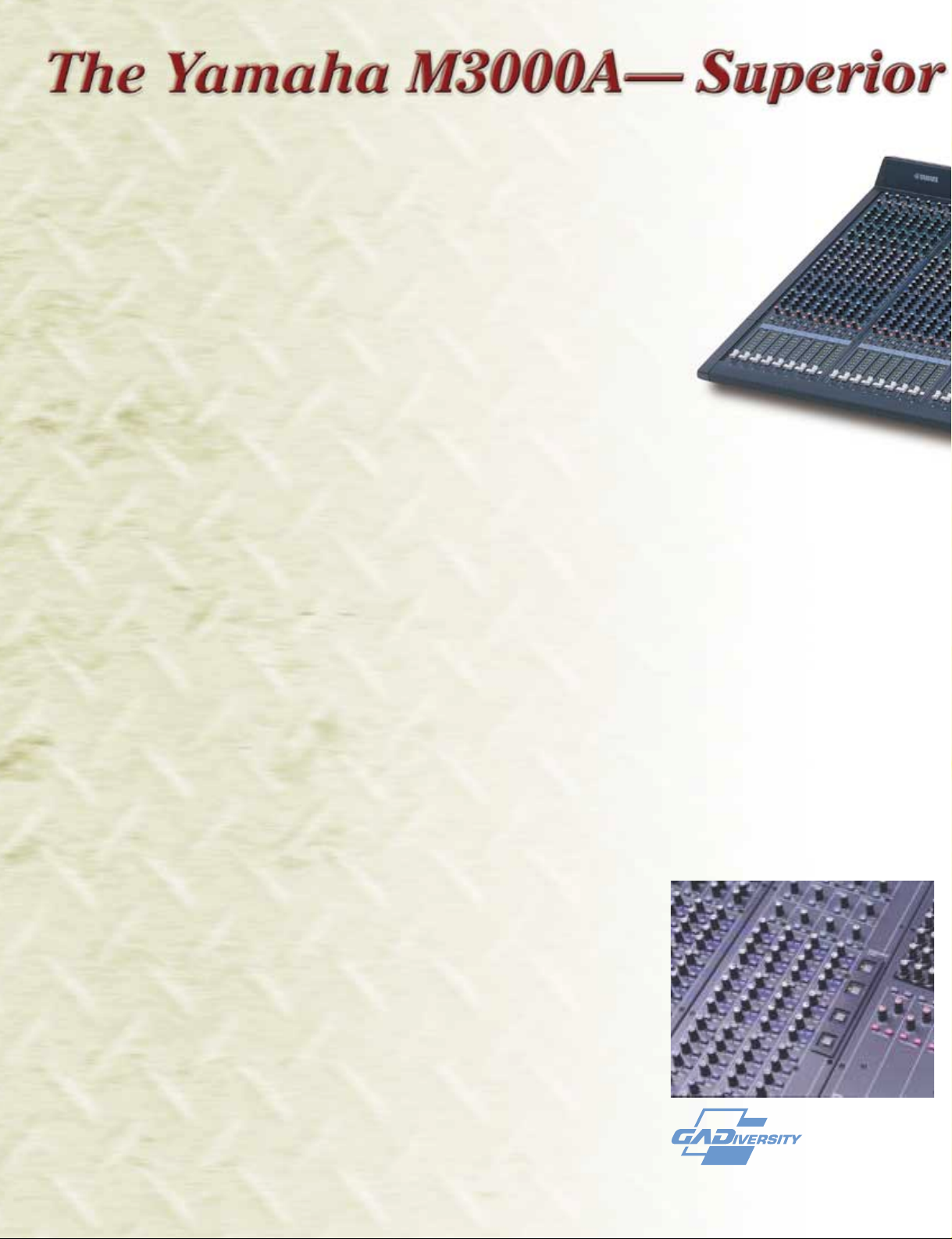
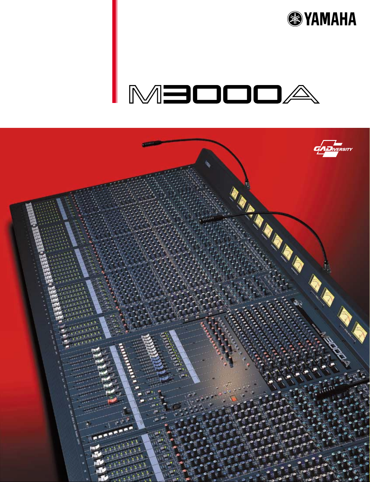
The superior quality and versatility of Yamaha professional audio consoles should be no
surprise to anyone who is familiar with sound reinforcement. The Yamaha M3000A,
however, is bound to raise a few eyebrows. It offers the same industry-leading
standards of audio quality and rugged reliability that Yamaha is famous for, plus a
number of innovative features for unprecedented versatility and applicability. And
best of all, its wide selection of input configurations—24, 40 and 56 input
models—are available at prices that are sure to make the budget-minded
professional smile.
Read on and learn how Yamaha has, once again, redefined the
leading edge of sound reinforcement.
●
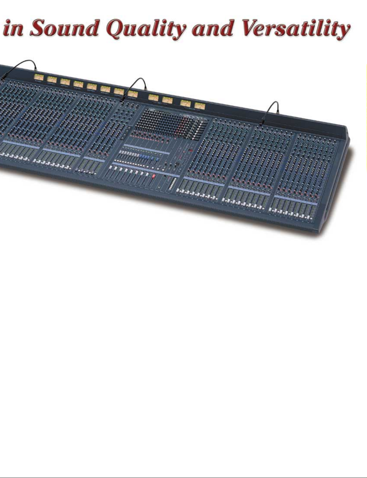
56, 40 or 24 mono channel configurations, both with 4 stereo
channels.
●
All mono inputs feature switchable phantom power, 26dB pad
switches, 44dB gain trim, phase switch, sweepable high-pass filter,
and fully-sweepable 4-band EQ.
●
16 mix busses with Yamaha’s GA (Group/Aux) Diversity system on
mix busses 1 through 8.
●
Mix busses 1 through 16 switchable for pre- or post-fader operation
in 4-buss groups.
●
Mix sends 13/14 and 15/16 configured as stereo sends with pan/
balance controls.
●
3-point signal indicators on all channels with SIGNAL, NOMINAL,
and PEAK LEDs.
●
All channels assignable to 8 VCA groups with full-length VCA
master faders and mute switches.
●
Balanced outputs for all 16 mix busses, the stereo buss, and the 8
matrix submixes.
●
20 x 8 submix matrix mixes signals from all 16 mix busses, the
stereo buss, and stereo matrix sub inputs.
●
Insert patch points on all input channels, all mix busses, and the
stereo outputs.
●
Memory for up to 128 mute scenes with 8 direct recall switches and
numeric keys for fast access to scenes.
●
Scene direct recall switches can alternatively be used as 8 mute
group switches.
●
MIDI-controlled scene recall or complete mute automation.
●
Dual stereo outputs with independent level control.
●
VCA EXTERNAL I/O connector allows linking two M3000As, or an
M3000A with another VCA-compatible Yamaha console.
●
All PFL/AFL switches are combined with an LED that lights when
the switch is on. Lock type push switches are also two-tone for
quick switch position recognition.
●
High-performance external power supply (two power supplies can
be parallel connected for automatic switchover in case of failure).
The Most Dynamic Buss
System Available
Most mixing consoles have a fixed buss
system: say 4 groups busses, 3 or 4
auxiliary busses, a stereo buss, and maybe
a mono buss. The numbers and variations
are endless, but you’re stuck with the
configuration you initially purchased. If
your buss requirements change, you need a
new console. And if your buss requirements change from project to project, you’ll
need a console with way more capacity
Page 3
than any single job requires. The
M3000A’s GA (Group/Aux) Diversity system
gives you the flexibility to match the
console’s buss configuration to a wide
range of signal-routing requirements. 8 of
its 16 mix busses can be switched from
auxiliary send status to group type operation in 2-buss groups, so you can have 2
groups and 14 auxiliary sends, 6 groups
and 10 auxiliary sends, or any other
combination the job requires.
Features For Unmatched
Control Flexibility
In addition to the GA Diversity system,
the M3000A expands the limits of console
control versatility with several innovative
features. A scene memory with MIDIcontrol capability, for example, lets you
store and instantly recall mute settings for
all input channels and mix busses output
from the panel controls, or from an external
MIDI device. You can even use a MIDI
sequencer or a computer running MIDI
sequencing software for total mute automation. Then there’s VCA grouping: all input
channels can be individually assigned to
any of 8 VCA groups, then the corresponding VCA master fader will simultaneously
control the relative levels of all assigned
channels via VCAs built right into the
channel strips so that no signal degradation
occurs. And how about a 20 x 8 submix
matrix output that can provide as many as
eight independent mixes of the signals on
the M3000A’s 16 mix busses, the stereo
buss, and matrix sub inputs?
We have no way of knowing exactly what
you need from a mixing console, but we
have spared no effort or expense in ensuring that the M3000A offers the versatility
you need to get any job done with maximum ease and efficiency.
Clean Signals From Input
To Output
Many mixer circuits must handle lowlevel signals - the head amplifiers, for
example - and must be designed with extra
care or they can be a major source of noise
and distortion. Other critical design criteria
include inter-stage matching, internal
impedance, circuit layout, grounding,
component selection, and a veritable
plethora of other factors that affect performance and the mixer’s overall “sound”.
Here’s where Yamaha technology makes a
real difference. Whether you’re using
microphone or line input, Yamaha’s highperformance circuitry gives you an exceptionally clean, quiet signal from input to
output. But then there’s RF rejection. RF
(Radio Frequency) noise generated by
motors, video monitors, and digital equipment of almost any kind can make the
cleanest, quietest circuitry virtually worthless. The M3000A boasts outstanding RF
noise rejection, so you can use it just about
anywhere without picking up unwanted
interference that can degrade your signal.
Specs You Can Trust
Yamaha never has “tweaked” specifications. Never will. It’s amazing how mediocre specs can be made to look impressive
by simply optimizing test conditions. The
electrical specifications we publish are all
brutally honest, measured under the stated
and/or industry-standard conditions. When
in doubt, we urge you to use the most
sensitive sound measurement devices
available: your own ears. They’ll tell you
who you can trust.
Rugged & Reliable
From connectors to controls to chassis,
the GA consoles are built to last. Whether
used in an installation or taken on the road,
these attractively-finished, rugged consoles
will keep on performing with the utmost
reliability.
Page 4

MONO & STEREO INPUT CHANNELS
MONO INPUTS
STEREO INPUTS
■ Inputs
The M3000A has 56, 40 or 24 mono and
4 stereo input channels with balanced
XLR-type microphone/line inputs. Phantom
power is independently switchable for all
mono inputs, providing direct compatibility
with high-performance phantom-powered
condenser microphones and DI boxes.
Stereo line sources can be directly
connected to either of 4 stereo input
channels (a total of eight inputs) via
switchable “A” or “B” inputs: the “A” inputs
are balanced XLR type connectors, and
the “B” inputs are standard RCA pin jacks
type for compatibility with the widest
possible range of line sources.
■ Channel Insertion
Insert send/return patch points are
included on all mono channels for convenient insertion of compressor/limiters (a
must for top-quality vocal sound), equalizers, or any other outboard equipment you
might need to apply to individual channels.
■ Input Controls & Level Matching
Gain trim controls with a 44dB range on
all mono inputs, and independent 40dB
gain controls for the A and B inputs on the
stereo channels, facilitate optimum level
matching with a wide range of sources.
The mono inputs additionally feature 26dB
pad switches and phase switches for easy
input phase correction.
■ Filters & Flexible 4-band
Channel EQ
All mono channels feature a switchable
high-pass filters, sweepable from 20 Hz to
400 Hz to effectively eliminate rumble and
other low-frequency noise. The mono
channels also feature a very flexible 4band equalizer which provides sweepable
frequencies for all four bands as well as
switchable bandwidth for the HI MID and
LO MID bands. The stereo channels offer
fixed-frequency 4-band equalization with
switchable HI MID and LO MID bandwidth.
EQ bypass switches are provided on all
channels so equalization can be punched
in or out as required without having to
change settings.
■ Eight Group/Aux Sends
The M1 through M8 “Mix Send” controls
feed the M3000A console’s unique GA
Diversity system. When a FIX/VAR switch
in the master section is set to the “VAR”
position, the corresponding pair of send
controls (1/2, 3/4, 5/6, or 7/8) function as
auxiliary sends: i.e. the send control
adjusts the level of the signal sent to the
corresponding mix buss, and the send
switch (M1 … M8) simply turns the
corresponding send on or off. If a FIX/VAR
switch is set to the “FIX” position, the
corresponding send controls then function
as post-fader group sends: The send
control is bypassed, and the send switch
functions as a group assign switch. For
even further flexibility the M1 through M4
control group and the M5 through M8
control group can be independently
switched for pre- or post-fader send.
■ Eight Aux Sends
The M9 through M12 controls function
as mono auxiliary sends, feeding the
corresponding mix buss. The remaining
four sends are configured as dual stereo
sends (13/14 and 15/16) with balance
controls. These controls can be switched
to receive the pre- or post-fader signal in
groups of four (i.e. the four mono sends as
one group and the two stereo sends as the
second group).
■ Stereo Assign & Pan/Balance
Controls
Stereo assign switches and pan
controls on each mono channel - stereo
assign switches and balance controls on
the stereo channels - assign the corresponding channel signal to the console’s
stereo buss.
■ 3-point Level Indicators
All mono and stereo channels feature 3point level indicators for accurate monitoring of pre-fader signal levels. SIGNAL,
NOM (nominal), and PEAK LEDs provide a
broader “view” of channel signal levels
than the usual one- or two-LED indicators.
■ Channel Faders, Pre-fader
Listen, & Channel ON Switches
Smooth, noise-free 100-mm linear
faders make it easy to set up the optimum
balance between channels, while PFL
(Pre-Fader Listen) switches allow convenient solo monitoring of the channel’s prefader signal. All channels additionally
feature channel on switches that can be
used to switch the channel signal into or
out of the mix without changing any other
settings.
■ VCA Group Assign
A feature taken directly from Yamaha’s
industry-leading PM3500 series mixing
consoles, VCA grouping allows channels
to be grouped and assigned to any of
eight VCA master faders in the master
section without actually re-routing the
channel signals, thus maintaining unsurpassed signal quality. The VCA GROUP
switches (1 … 8) next to each channel
fader assign the channel to the corresponding VCA master fader. The highperformance VCAs (Voltage Controlled
Amplifiers) are located immediately before
the channel faders, and thus function in
essentially the same way as the channel
faders themselves, adjusting the level of
the channel’s post fader signal.
Page 5

MASTER CONTROLS
Page 6

■ GA Diversity FIX/VARI Switches
The core of the GA console’s innovative GA
Diversity system, these switches determine
whether the corresponding pairs of sends on
the input channels - M1 through M8 - function
as auxiliary or group sends (see “Eight Group/
Aux Sends” for more details).
■ Mix Buss Masters
The first eight mix buss master strips - M1
through M8 - receive either the aux signal or
the group signal from the channel sends,
depending on the setting of the corresponding
GA Diversity FIX/VARI switch. Mix masters M9
through M16 receive the auxiliary signal from
the corresponding channel send controls.
While M9 through M12 have independent
controls, M13 through M16 are configured as
dual stereo masters (M13/14 and M15/16).
Each of these mix master control groups has
its own linear fader as well as a “TO STEREO”
switch and pan control (balance controls on
the stereo pairs) which assign the mix buss
signal to the console’s stereo buss. “TO
MATRIX” switches assign the corresponding
mix master signal to the console’s matrix mix
(below). The mix buss master strips AFL (AfterFader Listen) switches for convenient solo
monitoring, and ON/EDIT switches equivalent
to those on the input channels.
■ Mix Outputs, Inserts & Sub Inputs
All 16 mix busses feed balanced XLR type
outputs. They also feature insert patch points
for auxiliary signal processing, as well as sub
inputs which allow external line-level signals to
be individually added to the mix signals as
required.
■ Dual Stereo Masters
The stereo buss feeds two stereo output
pairs: stereo A and stereo B. The main linear
stereo fader feeds the balanced stereo A
outputs, with AFL listen capability and a “TO
MATRIX” routing switch. The stereo B signal
feeds a second balanced output pair via the
rotary stereo B level control.
■ Submix Matrix
The matrix mix concept was a Yamaha
innovation which has virtually become an
industry standard in professional audio
consoles. The M3000A features a 20 x 8
matrix mix which allows the 16 mix buss
signals, the stereo A signals, and the matrix L
and R sub input signals to be mixed to eight
balanced outputs for extra stage monitor
mixes, zoned speaker mixes, or just about any
type of mix the job requires. All eight matrix
mixes include mix on/off switches and AFL
switches.
■ VCA Group Masters
The eight VCA group masters include a 100mm linear fader which controls the assigned
channel VCAs (see “VCA Group Assign”), a
VCA mute switch which mutes the assigned
channel VCAs, and a nominal level LED.
A VCA EXTERNAL I/O connector allows two
M3000A consoles to be connected - or an
M3000A can be connected to any other VCAcompatible Yamaha console such as the
PM3500 - for linked VCA group control.
■ 128 MIDI Scene Memory/
8 Mute Groups
The M3000A console the channel, mix
master, and stereo A on/off functions are
electronically controlled by a microcomputer
and MIDI interface. Up to 128 mute “scenes”
can be stored in memory and recalled either
via the panel controls or an external MIDI
device. Eight DIRECT RECALL switches can be
used for instant recall of the most often-used
scenes, while others can be recalled via the
numeric keys. The memory contents can be
checked and edited at any time without
actually affecting the mix.
A utility function allows the DIRECT RECALL
switches to be re-assigned for “mute group”
switching, which allows mutiple mute scenes
to be engaged at the same, adding the mute
assignments for all active scenes.
In addition to recalling complete scenes,
external MIDI control can be used to individu-
ally turn the applicable channels and busses
off or on as required. A MIDI sequencer or
computer, for example, could be used for
complete mute automation. And since the
M3000A also transmits MIDI program change
messages whenever a scene is recalled, it can
be linked to MIDI-controllable signal processors so that appropriate effects are recalled
automatically. Furthermore, scene data can be
dumped to a MIDI data recorder or other
storage device for long-term storage.
■ Flexible Monitoring & Metering
Convenient monitoring is provided by
balanced monitor outputs and phones output
with independent level controls. In addition to
monitoring the stereo buss, the monitor signal
can be derived from either of the M3000A’s
two 2TR IN tape inputs. There’s also a L+R
switch which sums the left- and right-channel
signals for mono monitoring.
A total of 12 large, illuminated VU meters
with built-in peak-reading LEDs provide
accurate visual level monitoring. Eight of these
can be switched to display the levels on mix
busses 1 through 8 or 9 through 16, or the
levels at the eight matrix outputs. The remaining four display the stereo A L and R and cue L
and R levels.
■ Oscillator/Talkback Module
In addition to a panel microphone connector, level control and switch for talkback, the
M3000A includes a versatile oscillator which
provides pink noise as well as 10 kHz, 1 kHz,
and 100 Hz sine waves for precise calibration
and testing. The oscillator signal is assignable
to the mix busses in pairs or groups of four
(1/2, 3/4, 5/6. 7/8, 9 through 12, and 13
through 16) and/or the stereo buss.
■ Lamp Connectors
Connectors for up to three Yamaha LA1800
console lamps are provided on the M3000A
rear panel.
PW3000MA Power Supply
A newly developed, high-performance PW3000MA power supply unit is available as an
optional accessory for the M3000A mixing console. Two PW3000MA units can be
parallel connected so that if one fails the other will automatically take over — with no
need for any extra automatic switchover equipment.
PW3000MA Specifications
Power consumption
U.S. and Canadian model: 120V AC,60Hz / 500W 600 VA
European model: 230V AC, 50Hz/ 500W
Australian model: 240V AC, 50Hz/ 500W
Dimensions (H × D × W)
103.5 × 455 × 480 mm (4-1/16” × 17-5/16” × 18-7/8”)
Weight 15kg (33.1 Ibs)
Accessory Connecting cable (1m) × 1
Rear Panel
Page 7

M3000A-56C Front and Rear Panels
M3000A-40C Front and Rear Panels
M3000A-24 Front and Rear Panels
Page 8

BLOCK DIAGRAM
(SUB)(ST)
M1-M8
to Meter
ST OUT (+4dB)
MIX SUB IN (+4dB)
from ST CH
from INPUT
CUE SUB IN (+4dB)
L
R
CUE CONTROL
CUE SUB IN
to PFL L
to PFL R
to PFL ON
to PFL L
to PFL R
to PFL ON
ON
from ST CH
from Ctrl Master
from Ctrl Master
from Ctrl Master
from MIX
from INPUT
ST SUB IN (+4dB)
ST SUB IN
L
R
STEREO TO MATRIX (0dB)MIX TO MATRIX (0dB)
MATRIX SUB IN (+4dB)
LEVEL
MONITOR L+R (–3dB)
MATRIX OUT (+4dB)
LEVEL, PHONES
+30dB
+20dB
+10dB
0dB
–10dB
–20dB
–30dB
–40dB
–50dB
–60dB
PHONES (10mW@8 ohms)
MONITOR OUT (+4dB)
2TR IN 2 (–10dBV)
2TR IN 1 (+4dB)
STEREO TO MONITOR (0dB)MIX TO STEREO (0dB) ST INSERT I/O (0dB)
Talkback LEVEL
Ch Fader
MIX INSERT I/O (0dB)
MIX Master Fader ST Master Fader
MIX OUT (+4dB)
(ST Ch) MIX1-12(VARIABLE) (–9dB)
(Mono Ch) MIX(VARIABLE), (ST Ch) MIX13-16 (–6dB)
MIX(FIX), STEREO, PFL (0dB)
DIRECT OUT (0dB)
INSERT I/O (0dB)
MIX SUB IN
to ST R
to ST L
MIC(Talkback in)(–50dB)
Max before clip
GAIN Max (–30dB)
GAIN Max (–20dB)
ST CH INPUT A
ST CH INPUT B
ST CH INPUT A/B
GAIN Min (+10dB)GAIN Min (+10dB)
GAIN Min (–16dB)
GAIN Max (–34dB)
PAD 26dB
PAD 26dB
PAD 0dB
PAD 0dB
GAIN Max (–60dB)
–60dB
–50dB
–40dB
–30dB
–20dB
–10dB
0dB
+10dB
+20dB
+30dB
1
2
7
8
from VCA Master
CONTROL
ONCHECK
ON/EDIT
from Ctrl Master
from Ctrl Master
to Mute Control
Ctrl Master
METER SEL
DIRECT
RECALL
MEMORY
MIDI
to Meter select
to INPUT, ST CH
from VCA Master
OUT
IN
THRU
MATRIX
M9-M16
ON/OFF
1kHz
100Hz
10kHz
PINK
CHECK
STORE
RECALL
UTILITY
890
ENTER
8
7
2
1
1
2
ON/EDIT
CHECK ON
CONTROL
ON/EDIT
CHECK ON
CONTROL
CONTROL
ONCHECK
ON/EDIT
ON/EDIT
CHECK ON
CONTROL
MIX 15-16: Same as MIX 13-14
MIX 10, 11, 12: Same as MIX 9
MIX 3-4, 5-6, 7-8: Same as MIX 1-2
MIX 2: Same as MIX 1
ON
from
STEREO B R
CUE R
STEREO B L
CUE L
from
from
from
from
from
from
from
from
from
from STEREO A R
from STEREO A L
MIX 8
MIX 16
MATRIX 8
MIX 7
MIX 15
MATRIX 7
MIX 6
MIX 14
MATRIX 6
MIX 5
MIX 13
MATRIX 5
MIX 4
MIX 12
MATRIX 1
MIX 3
MIX 11
MATRIX 4
MIX 2
MIX 10
MATRIX 2
MIX 1
MIX 9
MATRIX 1
to Meter
to Meter
to Meter
to Meter
to Meter
to ST L
to ST R
INPUT
MASTER
VCA
MASTER/SLAVE
VCA
EXTERNAL I/O
VCA MUTE
NOMINAL
VCA MUTE
NOMINAL
VCA MUTE
NOMINAL
ST
LEVEL
BA
OFF/ON
MIC HA
NOMINAL
VCA MUTE
ON
L+R
ON
BA
BABABA
Phones
PHONES
10
928
16
1
2TR IN
2
1
1/2
BA
BA
BA
BA
L
R
L
R
MASTER PFL
LEVEL
L
R
MONITOR
OUT
VARIABLE
FIX
AFL
AFL
TO MATRIX
to AFL ON
to MAS PFL L
to MAS PFL R
to MAS AFL L
to MAS AFL R
AFL
TO MATRIX
TO MATRIX
PAN
TO STEREO
AFL
to MAS AFL L
to MAS AFL R
to MAS PFL L
to MAS PFL R
to AFL ON
to AFL ON
to MAS PFL L
to MAS PFL R
to MAS AFL L
to MAS AFL R
MATRIX
SUB IN
R
L
BA
BA
AFL
PFL
LRON
MAS
AFL
MAS
LR
PFL
STEREO A
L
SUB INLSUB IN
R
STEREO A
R
LEVEL ON
MATRIX
OUT 1-8
to
Meter
AFL
(MIX)
TO MATRIX
LEVEL
ST OUT B
L
R
ST
INSERT
I/O LSTINSERT
I/O R
R
L
ST OUT A
CONTROL
ONCHECK
ON/EDIT
BAL
TO STEREO
MIX OUT 14
MIX
INSERT
I/O
MIX
INSERT
I/O
MIX OUT 13
MIX OUT 9
MIX OUT 1
AFL
TO STEREO
PAN
TO MATRIX
MIX
INSERT
I/O
ST
RL
LR
MIX
(FIX)
MIX
(VARIABLE)
B
A
M15
M16
HA
HA
GAIN A GAIN A
BAL
M13
M14
BAL
PRE
M1
PRE
PRE
M9
M10
M11
M12
PFL
M2
M3
M4
PRE
M5
M6
M7
M8
M8
M7
M6
M5
PRE
M4
M3
M2
BAL
VCA
ST CH
1-4
INPUT A
INPUT B
R
L
R
L
4 Stage EQ
HA
HA
EQ
4 Stage EQ
VCA
ST
8
7
2
1
PFL
DIRECT OUT
Internal Jumper
PRE
M15/
M16
M13/
M14
PAN
PAN
M12
M11
M10
M9
PRE
PRE
M1
PEAK
NOM
SIGNAL
ST
VCA
INSERT I/O
4 Stage EQ
EQHPF
HPF
PHANTOM
MASTER
+48V
Input
1-24/1-40
+48V
26dB
PAD
PAN
HA
GAIN
PEAK
NOM
SIGNAL
MIX
INSERT
I/O
1 3 5 7 12345678
2468
9111315
10 12 14 16
M1M2M3M4M5M6M7M8M9
M10
M11
M12
M13
M14
M15
M16
M1-M2
M3-M4
M5-M6
M7-M8
M9-M12
M13-M16
f
g
f
g
f
g
Q
f
g
Q
LO
LO-MID
HI-MID
HI
LO
LO-MID
HI-MID
HI
g
Q
g
g
g
Q
M1/M9/MATRIX 1
M2/M10/MATRIX 2
M3/M11/MATRIX 3
M4/M12/MATRIX 4
M5/M13/MATRIX 5
M6/M14/MATRIX 6
M7/M15/MATRIX 7
M8/M16/MATRIX 8
STEREO A L
STEREO A R
STEREO B/CUE L
STEREO B/CUE R
from Ctrl Master
from Ctrl Master
1357
2468
9111315
10 12 14 16
LR
LR
Page 9

Input specifications
405.6mm (15-15/16")49.4mm
(1-15/16")
455mm (17-5/16")
292mm (11-1/2")56.8mm
(2-1/4")
480mm (18-7/8")
308mm (12-1/8")
86mm
(3-3/8")
86mm
(3-3/8")
88mm
(3-16/7")
103.5mm
(4-1/16")
noitcennoCDAP
TUPNIHC
)42~1(
)04~1(
)65~1(
)4~1(]R,L[
)4~1(]R,L[
0
62
0
62
TUPNIAHCTS
TUPNIBHCTS
NIKCABKLATk01 Ω 006–05 Ω sciM
]R,L[1NIRT2
]R,L[2NIRT2
]R,L[NIBUSEUC
]R,L[NIBUSXIRTAM
)61~1(NIBUS
)04,42~1(NITRESNIHC
)61~1(NITRESNI
0 dB=0.775 Vrms.
*1 XLR connectors are balanced.
*2 XLR connector is unbalanced.
*3 Phone Jacks are unbalanced.
Output specifications
niaG
mirT
− 06
− 61
− 03
+ 01 − )Vm321(Bd61 + )V54.2(Bd01 + )V5.42(Bd03
− 02
+ 01
daoLlautcA
ecnadepmI
k3 Ω
006–05 Ω sciM
&
006 Ω seniL
k5 Ω 006 Ω seniL
k01 Ω 006 Ω seniL
htiWesUroF
lanimoN
6*ytivitisneSlanimoNpilCerofebxaM
− )Vm930.0(Bd68 − )Vm577.0(Bd06 − )Vm577.0(Bd04
− )Vm577.0(Bd06 − )Vm5.51(Bd43 − )Vm551(Bd41
− )Vm61.6(Bd24 − )Vm321(Bd61 + )V32.1(Bd4
− )Vm321(Bd61 + )V54.2(Bd01 + )V5.42(Bd03
− )Vm32.1(Bd65 − )Vm5.42(Bd03 − )Vm542(Bd01
− )Vm88.3(Bd64 − )Vm5.77(Bd02
− )Vm321(Bd61 + )V54.2(Bd01 + )V5.42(Bd03
leveLtupnI
− )Vm883.0(Bd66 − )Vm54.2(Bd05 − )Vm5.77(Bd02
k01 Ω 006 Ω seniL
− )V616.0(Bd2 + )V32.1(Bd4 + )V3.21(Bd42
− )Vm851(Bd8.31 − )Vm613(Bd8.7 + )V51.3(Bd2.21
− )V616.0(Bd2
XIM]R,L[NIBUSOERETS
k01 Ω 006 Ω seniL
− )Vm883(Bd6
)V32.1(Bd4+
− )Vm8.83(Bd62
XIM]R,L[NITRESNIOERETS
k01 Ω 006 Ω seniL
*4 SUB IN Phone Jacks (TRS) are unbalanced (T=SIGNAL, R=GND, S=GND).
*5 INSERT Phone Jacks (TRS) are unbalanced (T=OUTPUT, R=INPUT, S=GND).
*6 Sensitivity is the lowest level that will produce an output of +4 dB (1.23 V), or the nominal
output level when the unit is set to maximum level.
− )Vm542(Bd01
)V577.0(Bd0
rexiMnIrotcennoC
1*epyt13-3-RLX
1*epyt13-3-RLX
)V577.0(Bd0
3*kcaJenohP
2*epyt13-3-RLX
1*epyt13-3-RLX
3*kcaJenohP
+ )V3.21(Bd42
+ )V57.7(Bd02
4*)SRT(kcaJenohP
5*)SRT(kcaJenohP
noitcennoC
]R,L[TUOAOERETS
]R,L[TUOBOERETS
)61~1(TUOXIM
]R,L[TUOROTINOM
)8~1(TUOXIRTAM
)04,42~1(TUOTCERIDHC
)04,42~1(TUOTRESNIHC
]R,L[TUOTRESNIOERETS
)61~1(TUOTRESNIXIM
]R,L[TUOSENOHP001 Ω
• 0 dB=0.775 Vrms.
*1 All XLR connectors are balanced.
*2 CH DIRECT OUT Phone Jacks (TRS) are unbalanced (T=SIGNAL, R=GND, S=GND).
ecruoSlautcA
ecnadepmI
051 Ω 006 Ω seniL
006 Ω k01 Ω seniL)V577.0(Bd0
006 Ω k01 Ω seniL)V577.0(Bd0
8 Ω senohPWm1Wm02
04 Ω senohPWm3Wm57
M3000A Dimensions
lanimoNhtiWesUroF
lanimoNpilCerofebxaM
leveLtuptuO
+ )V32.1(Bd4 + )V3.21(Bd42
+ )V57.7(Bd02
+ )V57.7(Bd02
*3 INSERT Phone Jacks (TRS) are unbalanced (T=OUTPUT, R=INPUT, S=GND).
*4 Stereo Phone Jack is unbalanced.
PW3000MA Dimensions
265mm (10-7/16")
(34-3/8")
m
874m
rexiMnIrotcennoC
1*epyt23-3-RLX
2*)SRT(kcaJenohP
3*)SRT(kcaJenohP
4*kcaJenohPoeretS
M3000A-24: 1515mm (59-5/8")
M3000A-40C: 2043mm (80-7/16")
M3000A-56C: 2571mm (101-1/4")
Page 10

General specifications
Total Harmonic Distortion Less than 0.1% (THD + N)
(Master output) 20 Hz–20 kHz @ +14 dB 600 Ω
Frequency Response 0 + 1, -3 dB
(Master Output) 20 Hz–20 kHz @ +4 dB 600 Ω
Hum & Noise (20 Hz–20 kHz) *1 −128 dB Equivalent Input Noise.
Rs = 150 Ω−97 dB Residual Output Noise.
Input Gain = Max. −99 dB Residual Output Noise. (OTHERS)
Input Pad = OFF
||
Input sensitivity=-60 dB
Crosstalk
Maximum V oltage Gain
CH INPUT PAD SW 26 dB
CH INPUT GAIN control 44 dB variable
ST CH INPUT GAIN control 40 dB variable (ST CH A INPUT)
CH INPUT High Pass Filter 12 dB/octave roll-off below 20–400 Hz at −3 dB
CH INPUT Equalization
−64 dB (68 dB S/N) MIX OUT Master Level control and one CH
−80 dB (84 dB S/N) STEREO OUT Master fader at nominal level and
−75 dB (79 dB S/N) MIX OUT (VARIABLE) Master Level control at
−81 dB (85 dB S/N) MIX OUT (FIX) Master Level control at nominal
−90 dB (94 dB S/N) MATRIX OUT Master level control at nominal
−80 dB @ 1 kHz adjacent inputs.
−70 dB @ 1 kHz input to output. (CH INPUT)
−50 dB @ 1 kHz input to output. (ST CH INPUT)
70 dB CH INPUT to DIRECT OUT
60 dB CH INPUT to CH INSERT OUT
80 dB CH INPUT to MIX OUT (VARIABLE, Pre Fader)
90 dB CH INPUT to MIX OUT (VARIABLE, Post Fader)
84 dB CH INPUT to MIX OUT (FIX; 1–8, Post Fader)
84 dB CH INPUT to STEREO A OUT (CH to ST)
80 dB CH INPUT to STEREO B OUT (CH to ST)
100 dB CH INPUT to STEREO A OUT (VARIABLE,
96 dB CH INPUT to MATRIX OUT (VARIABLE,
70 dB CH INPUT to MONITOR OUT (PFL)
47 dB ST CH A INPUT to MIX OUT (VARIABLE;1–12,
54 dB ST CH A INPUT to MIX OUT (FIX;1–8)
44 dB ST CH B INPUT to MIX OUT (FIX;1–8)
70 dB TALKBACK IN to MIX OUT
6 dB SUB IN to STEREO B OUT, MONITOR OUT,
10 dB SUB IN to STEREO A OUT, MIX OUT
6 dB 2TR IN 1 to MONITOR OUT
17.8 dB 2TR IN 2 to MONITOR OUT
+15, −15 dB maximum
HIGH 1k–20 kHz (peaking, Q=0.667)
HIGH-MID 400 –8 kHz (peaking, Q=1.41/2.88)
LOW-MID 80–1.6 kHz (peaking, Q=1.41/2.88)
LOW 30–600 Hz (peaking, Q=0.667)
fader at nominal level.
all CH assign SW’s off and all MIX to ST SW’s
off.
nominal level and all CH assign SW’s off.
level and all CH assign SW’s off.
level and all Matrix Mix controls at minimum
level.
MIX; Post Fader) (via MIX to ST)
MIX; Post Fader) (via MIX to MATRIX)
Pre Fader)
MATRIX OUT
30 dB variable (ST CH B INPUT)
point.
(MATRIX[1-8] Output)
ST CH INPUT Equalization
Phantom Power +48VDC is applied to balanced inputs (via 6.8 kΩ current-limiting/
CH LED Indicators
ST CH LED Indicators
Oscillator/Noise
Scene Memory
VU Meters
VU Meter Peak Indicators
Dimension
Weight 56C: 128 kg (282.2 Ibs.), 40C: 108 kg (238.1 Ibs.), 24: 85 kg (187.4 Ibs.)
Accessory
●
*1 Hum & Noise are measured with a 6 dB/octave filter @ 12.7 kHz;equivalent to a
+15, −15 dB maximum
HIGH 20 kHz (peaking, Q=0.667)
HIGH-MID 3 kHz (peaking, Q=1.41/2.88)
LOW-MID 800 Hz (peaking, Q=1.41/2.88)
LOW 50 Hz (peaking, Q=0.667)
isolation resistors) for powering condenser microphones ; may be turned
ON or OFF via rear-panel phantom Master switch.
When Master is ON, individual channels may be turned ON or OFF via
+48V switches (with red LED) on each input channel.
PEAK LED (red) built into each CH INPUT turns on
NOM LED (yellow) built into each CH INPUT turns on
SIGNAL LED (green) built into each CH INPUT turns on
PEAK LED (red) built into each ST CH INPUT turns on
NOM LED (yellow) built into each ST CH INPUT turns
SIGNAL LED (green) built into each ST CH INPUT turns
Switchable sine wave @ 100 Hz, 1 kHz or 10 kHz (1% T.H.D. @ +4 dB
output), or pink noise.
Direct Scene Memory recall switches (1–8)
Switchable Scene Memory recall (1–128)
12 illuminated meters
(0VU= +4 dB output @ 600 Ω load)
#1 ; MIX1 / MIX9 / MATRIX1
#2 ; MIX2 / MIX10 / MATRIX2
#3 ; MIX3 / MIX11 / MATRIX3
#4 ; MIX4 / MIX12 / MATRIX4
#5 ; MIX5 / MIX13 / MATRIX5
#6 ; MIX6 / MIX14 / MATRIX6
#7 ; MIX7 / MIX15 / MATRIX7
#8 ; MIX8 / MIX16 / MATRIX8
#9 ; STEREO A L
#10; STEREO A R
#11; STEREO B L / CUE L
#12; STEREO B R / CUR R
LED(red) built into each VU meter turns on when output signal is above
the level 3 dB lower than clipping level.
Height 265 mm (10-6/7”)
Depth 874 mm (34-3/8”)
Width 56C: 2571 mm (101-1/4”)
Connecting cable (3m) × 1
when pre-Fader level reaches +18 dB.
when pre-Fader level reaches 0 dB.
when pre-Fader level reaches −10 dB.
when pre-Fader [L+R] level reaches +18 dB.
on when pre-Fader [L+R] level reaches 0 dB.
on when pre-Fader [L+R] level reaches −10 dB.
40C: 2043mm (80-7/16”)
24: 1515mm (59-5/8”)
0 dB is referenced to 0.775 Vrms.
20 kHz filter with infinite dB/octave attenuation.
All specifications subject to change without notice.
For details please contact:
http://www.yamaha.co.jp/english
Y AMAHA W eb Site
http://www.yamaha.co.jp/product/proaudio/homeenglish/
This document is printed on chlorine free (ECF) paper.
LPA438 0033 Printed in Japan
 Loading...