

Page 1
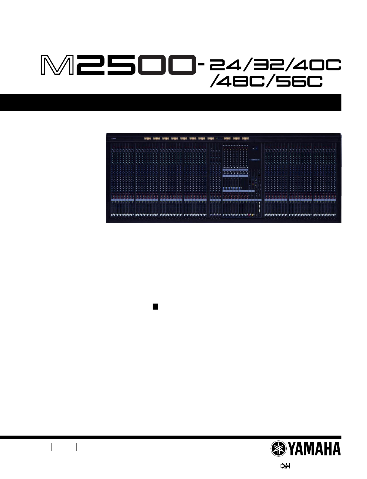
M2500
MIXING CONSOLE
SERVICE MANUAL
M2500-56C
CONTENTS
SPECIFICATIONS .............................................. 3/5
DIMENSIONS ............................................................ 8
PANEL LAYOUT ..................................... 9
CIRCUIT BOARD LAYOUT .............. 16
DISASSEMBLY PROCEDURE ............................ 18
LSI PIN DESCRIPTION .............................. 26
IC BLOCK DIAGRAM ................................... 30
CIRCUIT BOARDS ....................................... 33
INSPECTIONS ....................................................... 61/69
TEST PROGRAM ............................. 76/78
ERROR MESSAGES ....................... 80/81
MIDI IMPLEMENTATION CHART ......................................... 82
CIRCUIT DIAGRAMS
PARTS LIST
011484
PA
M2500-24 20000220-850000
M2500-32 20000220-1000000
M2500-40C 20000220-1150000
1/2
M2500-48C 20000220-1300000
M2500-56C 20000220-1450000
PW3000MA 20000220-100000
HAMAMATSU, JAPAN
1.50K-5972 Printed in Japan 2000.02
1
Page 2
M2500
IMPOR TANT NOTICE
This manual has been provided for the use of authorized Yamaha Retailers and their service personnel. It has been assumed
that basic service procedures inherent to the industry, and more specifically Yamaha Products, are already known and understood by the users, and have therefore not been restated.
WARNING : Failure to follow appropriate service and safety procedures when servicing this product may result in per-
IMPORTANT : This presentation or sale of this manual to any individual or firm does not constitute authorization certifi-
The data provided is belived to be accurate and applicable to the unit(s) indicated on the cover. The research engineering, and
service departments of Yamaha are continually striving to improve Yamaha products. Modifications are, therefore, inevitable
and changes in specification are subject to change without notice or obligation to retrofit. Should any discrepancy appear to
exist, please contact the distributor’s Service Division.
WARNING : Static discharges can destroy expensive components. Discharge any static electricity your body may have
IMPORTANT : Turn the unit OFF during disassembly and parts replacement. Recheck all work before you apply power
sonal injury, destruction of expensive components and failure of the product to perform as specified. For
these reasons, we advise all Yamaha product owners that all service required should be performed by an
authorized Yamaha Retailer or the appointed service representative.
cation, recognition of any applicable technical capabilities, or establish a principal-agent relationship of
any form.
accumulated by grounding yourself to the ground bus in the unit (heavy gauge black wires connect to
this bus.)
to the unit.
LITHIUM BA TTERY HANDLING
This product uses a lithium battery for memory back-up.
WARNING : Lithium batteries are dangerous because they can be exploded by improper handling. Observe the following pre-
Leave lithium battery replacement to qualified service personnel.
Always replace with batteries of the same type.
When installing on the PC board by soldering, solder using the connection terminals provided on the battery cells.
Never solder directly to the cells. Perform the soldering as quickly as possible.
Never reverse the battery polarities when installing.
Do not short the batteries.
Do not attempt to recharge these batteries.
Do not disasemble the batteries.
Never heat batteries or throw them into fire.
ADVARSEL!
Lithiumbatteri-Eksplosionsfare ved fejlagtig handtering. Udskiftning ma kun ske med batteri af samme fabrikat og type. lever det brugte
batteri tilbage til leverandren.
VARNING
Explosionsfara vid felaktigt batteribyte.
Anvand samma batterityp eller en ekvivalent typ som rekommenderas av apparattillverkaren.
Kassera anvant batteri enligt fabrikantens instruktion.
VAROITUS
Paristo voi rajahtaa, jos se on virheellisesti asennettu.
Vaihda paristo ainoastaan laitevalmistajan suosittelemaan tyyppiiin.
Havita kaytetty paristo valmistajan ohjeiden mukaisesti.
The following information complies with Dutch official Gazette 1995. 45; ESSENTIALS OF ORDER ON THE COLLECTION OF BATTERIES.
• Please refer to the diassembly procedure for the removal of Back-up Battery.
• Leest u voor het verwijderen van de backup batterij deze beschrijving.
cautions when handling or replacing lithium batteries.
WARNING: CHEMICAL CONTENT NOTICE!
The solder used in the production of this product contains LEAD. In addition, other electrical/electronic and/or plastic (Where
applicable) components may also contain traces of chemicals found by the California Health and Welfare Agency (and possibly
other entities) to cause cancer and/or birth defects or other reproductive harm.
DO NOT PLACE SOLDER, ELECTRICAL/ELECTRONIC OR PLASTIC COMPONENTS IN YOUR MOUTH FOR ANY REASON WHAT
SO EVER!
Avoid prolonged, unprotected contact between solder and your skin! When soldering, do not inhale solder fumes or expose
eyes to solder/flux vapor!
If you come in contact with solder or components located inside the enclosure of this product, wash your hands before handling
food.
WARNING
Components having special characteristics are marked and must be replaced with parts having specification equal to those
originally installed.
2
Page 3
SPECIFICATIONS
M2500
General specifications
0 dB is referenced to 0.775 Vrms.
Total Harmonic Distortion Less than 0.1% (THD+N)
(Master output) 20 Hz–20 kHz @ +14 dB 600 Ω
Frequency Response 0+1, –3 dB
(Master Output) 20 Hz–20 kHz @ +4 dB 600 Ω
Hum & Noise (20 Hz–20 kHz)*1
Rs= 150 Ω –99 dB Residual Output Noise.
Input Gain= Max.
Input Pad= OFF
||
Input sensitivity= –60 dB
–64 dB(68 dB S/N) STEREO OUT Master Level control and
–80 dB(84 dB S/N) STEREO OUT, MONO/C OUT Master f ader
–81 dB(85 dB S/N) GROUP1/AUX7–GROUP8/AUX14 OUT
–75 dB(79 dB S/N) AUX1–6, AUX7/GROUP1–AUX14/GROUP8
–90 dB(94 dB S/N) MATRIX OUT Master level control at nomi-
Crosstalk –70 dB @ 1 kHz adjacent inputs.
–70 dB @ 1 kH input to output. (CH INPUT)
–50 dB @ 1 kHz input to output. (ST CH INPUT)
Maximum Voltage Gain
GROUP/AUX FLIP SW= off
60 dB CH INPUT to CH INSERT OUT
84 dB CH INPUT to GROUP1/AUX7–GROUP8/
80 dB CH INPUT to AUX1, 2 OUT(Pre Fader)
90 dB CH INPUT to AUX3–6, AUX7/GROUP1–
84 dB CH INPUT to STEREO OUT(CH to ST)
70 dB CH INPUT to MONITOR OUT(PFL)
CH INPUT PAD SW 26 dB
CH INPUT GAIN control 44 dB variable
ST CH 1A, 2–4 INPUT GAIN control
ST CH 1B INPUT GAIN control
CH INPUT High Pass Filter 18 dB/octave
CH INPUT Equalization
+15, –15 dB maximum
HIGH 10 kHz (shelving)
HIGH-MID 400– 8 kHz (peaking)
LOW-MID 80–1.6 kHz (peaking)
LOW 100 Hz (shelving)
Gain control at minimum level
–128 dB Equivalent Input Noise.
(STEREO OUT, MONO/C OUT,
GROUP/AUX OUT, AUX OUT,
AUX/GROUP OUT)
one Ch fader at nominal level.
at nominal level and all Ch assign SW’s off
and all GROUP to ST SW’s off.
Master Level control at nominal lev el and all
Ch assign SW’s off.
GROUP/AUX FLIP SW off.
OUT Master Level control at nominal level
and all Ch send controls at minimum.
GROUP/AUX FLIP SW off.
nal level and all Matrix Mix controls at minimum level.
AUX14 OUT
AUX14/GROUP8 OUT(Post Fader)
40 dB variable
30 dB variable
roll-off below 80 Hz at –3 dB point.
ST CH INPUT Equalization
+15, –15 dB maximum
Phantom Power +48 VDC is applied to balanced inputs (via
CH LED Indicators
ST CH LED Indicators
Oscillator/Noise Switchable sine wave @ 100 Hz, 1 kHz or
Scene Memory Direct Scene Memory recall switches (1–8)
VU Meters 11 illuminated meters
VU Meter Peak Indicators LED(red) built into each VU meter turns on
Dimension Heigt 265 mm
Weight 102kg(56C), 93kg(48C), 84kg(40C),
*1 Hum & Noise are measured with a 6 dB/octave filter @ 12.7 kHz;
equivalent to a 20 kHz filter with infinite dB/octave attenuation.
For European Model
Purchaser/User information specified in EN55103-1 and EN55103-2.
Conformed Enviroment: E1, E2, E3 and E4.
PEAK LED(red) built into each CH INPUT turns on
NOM LED(yellow) b uilt into each CH INPUT turns
SIGNAL LED(green) built into each CH INPUT turns
PEAK LED(red) built into each ST CH INPUT turns
NOM LED(yellow) built into each ST CH INPUT
SIGNAL LED(green) built into each ST CH INPUT
#1 ; GROUP1/AUX7
#2 ; GROUP2/AUX8
#3 ; GROUP3/AUX9
#4 ; GROUP4/AUX10
#5 ; GROUP5/AUX11
#6 ; GROUP6/AUX12
#7 ; GROUP7/AUX13
#8 ; GROUP8/AUX14
#9 ; STEREO L
#10 ; MONO/C
#11 ; STEREO R
Depth 875 mm (except rear connectors)
Width 2385 mm(56C), 2142 mm(48C),
HIGH 10 kHz (shelving)
LOW 100 Hz (shelving)
6.8 kΩ current-limiting/isolation resistors) for
powering condenser microphones; may be
turned ON or OFF via rear-panel phantom
Master switch.
When Master is ON, individual channels
may be turned ON or OFF via +48V
switches (with red LED) on each input channel.
when pre-Fader level reaches +17 dB.
on when pre-Fader level reaches 0 dB.
on when pre-Fader level reaches –13 dB.
on when pre-Fader [L+R] level reaches
+17 dB.
turns on when pre-Fader [L+R] level
reaches 0 dB.
turns on when pre-Fader [L+R] level
reaches –13 dB.
10 kHz, or pink noise.
Switchable Scene Memory recall (1–128)
(0VU= +4 dB output @ 600Ω load)
•
AUX1•AUX7/GROUP1•MATRIX1
•
AUX2•AUX8/GROUP2•MATRIX2
•
AUX3•AUX9/GROUP3•MATRIX3
•
AUX4•AUX10/GROUP4•MATRIX4
•
AUX5•AUX11/GROUP5•MATRIX5
•
AUX6•AUX12/GROUP6•MATRIX6
•
NONE•AUX13/GROUP7•MATRIX7
•
NONE•AUX14/GROUP8•MATRIX8
•
PFL/AFL L
•
PFL/AFL R
when output signal is above the level 3 dB
lower than clipping level.
1899 mm(40C), 1642 mm(32),
1400 mm(24)
71kg(32), 62kg(24)
3
Page 4
M2500
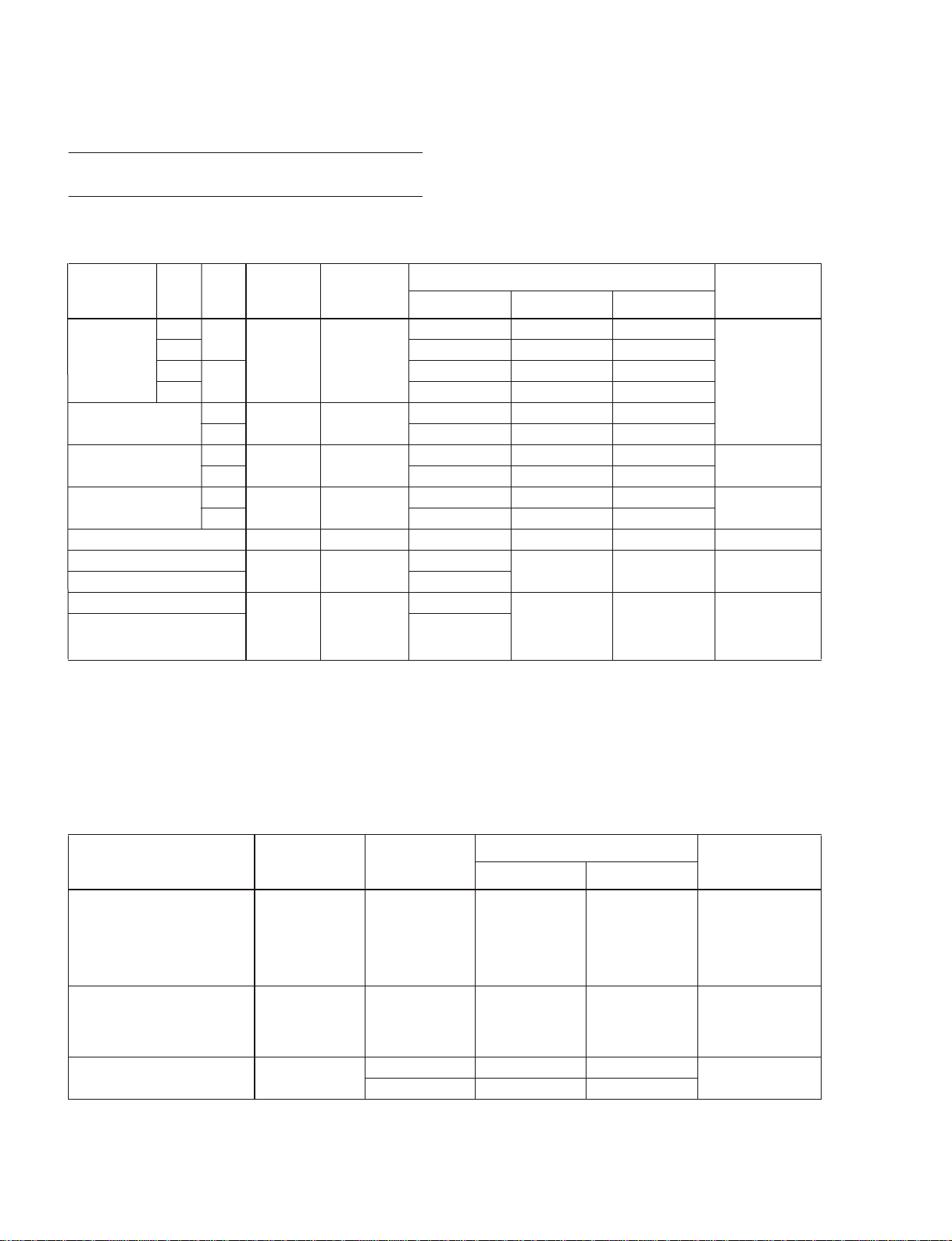
Input/output characteristics
Input specifications
Connection PAD
CH INPUT
*8
(1–n)
ST CH 1A INPUT
[L, R]
ST CH 1B INPUT
[L, R]
ST CH INPUT
[L, R] (2–4)
*9
Input Level
Nominal Max before Clip
Gain
Actual Load
Trim
Impedance
0
–60
26 –54 dB(1.55 mV) –34 dB(15.5 mV) –14 dB(155 mV)
0
–16
26 –10 dB(245 mV) +10 dB(2.45 V) +30 dB(24.5 V)
–30
+10 –10 dB(245 mV) +10 dB(2.45 V) +30 dB(24.5 V)
–20
+10 –10 dB(245 mV) +10 dB(2.45 V) +30 dB(24.5 V)
–30
+10 –10 dB(245 mV) +10 dB(2.45 V) +30 dB(24.5 V)
3 kΩ
5 kΩ 600 Ω Lines
10 kΩ 600 Ω Lines
5 kΩ 600 Ω Lines
For Use With
Nominal
50–600 Ω Mics
&
600 Ω Lines
Sensitivity
–80 dB(0.078 mV) –60 dB(0.775 mV) –40 dB(7.75 mV)
–36 dB(12.3 mV) –16 dB(123 mV) +4 dB(1.23 V)
–50 dB(2.45 mV) –30 dB(24.5 mV) –10 dB(245 mV)
–40 dB(7.75 mV) –20 dB(77.5 mV) 0 dB(0.775 V)
–50 dB(2.45 mV) –30 dB(24.5 mV) –10 dB(245 mV)
*1
Connector In
Mixer
XLR-3-31 type
Phono Jack
Phone Jack(TRS)
TALKBACK IN 10 kΩ 50–600 Ω Mics –66 dB(0.388 mV) –50 dB(2.45 mV) –20 dB(77.5 mV) XLR-3-31 type
MATRIX SUB IN [L, R]
STEREO [L, R] MONO/C SUB IN –6 dB(388 mV)
CH INSERT IN (1–n)
*8
STEREO [L, R] MONO/C INSERT IN
GRP/AUX INSERT IN (1/7–8/14)
10 kΩ 600 Ω Lines
10 kΩ 600 Ω Lines
–2 dB(0.616 V)
–26 dB(38.8 mV)
–10 dB(245 mV)
+4 dB(1.23 V) +24 dB(12.3 V) Phone Jack(TRS)
0 dB(0.775 V) +20 dB(7.75 V) Phone Jack(TRS)
AUX INSERT IN (1–6)
*1 0 dB=0.775 Vrms.
*2 Balanced.
*3 Unbalanced.
*4 Balanced (T=HOT, R=COLD, S=GND).
*5 Unbalanced.
*6 Unbalanced (T=SIGNAL, R=GND, S=GND).
*7 Unbalanced (T=OUTPUT, R=INPUT, S=GND).
*8 n=56, 48, 40, 32 or 24
*9 Sensitivity is the lowest level that will produce an output of +4 dB(1.23 V), or the nominal output level when the unit is set to maximum level.
*2
*3
*4
*5
*6
*7
Output specifications
Connection
STEREO OUT [L, R]
MONO/C OUT
GRP/AUX OUT (1/7–8/14)
AUX/GRP OUT (7/1–14/8)
AUX OUT (1–6)
MONITOR OUT [L, R, MONO/C]
MATRIX OUT (1–8)
CH INSERT OUT (1–n)
STEREO INSERT OUT [L, R]
MONO/C INSERT OUT
GRP/AUX INSERT OUT (1/7–8/14)
AUX INSERT IN (1–6)
PHONES OUT [L, R] 100 Ω
*1 0 dB=0.775 Vrms.
*2 Balanced.
*3 Unbalanced (T=OUTPUT, R=INPUT, S=GND).
*4 Unbalanced.
*5 n=56, 48, 40, 32 or 24
4
*5
Actual Source
Impedance
For Use With
Nominal
Output Level
Nominal Max before Clip
*1
Connector In Mixer
150 Ω 600 Ω Lines +4 dB(1.23 V) +24 dB(12.3 V) XLR-3-32 type
600 Ω 10 kΩ Lines 0 dB(0.775 V) +20 dB(7.75 V) Phone Jack(TRS)
8 Ω Phones 10 mW 20 mW
40 Ω Phones 30 mW 75 mW
Stereo Phone Jack
*2
*3
*4
Page 5
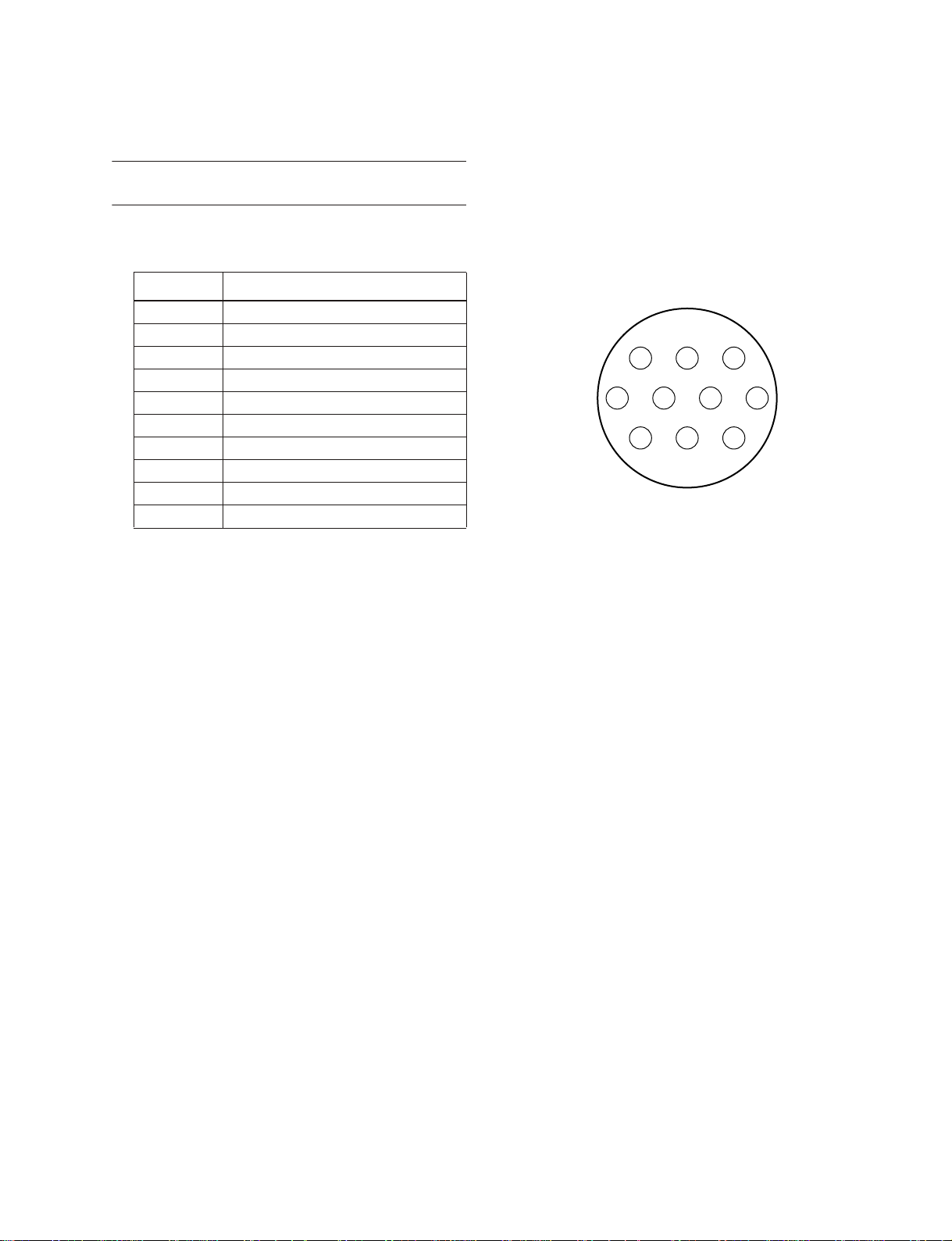
Other
Connector wiring
Pin No. Signal name
1 Power supply remote
2 +15 V
3 ±15 V GND
4 +48 V GND
5 –15 V
6 +12 V
7 +12 V GND / power supply remote
8 Power supply remote
9 +48 V
10 FRAME GND
M2500
3 2 1
7 6 5 4
10 9 8
Included items
Power supply connection cable (3 m, 10 pin)
7
Page 6
M2500
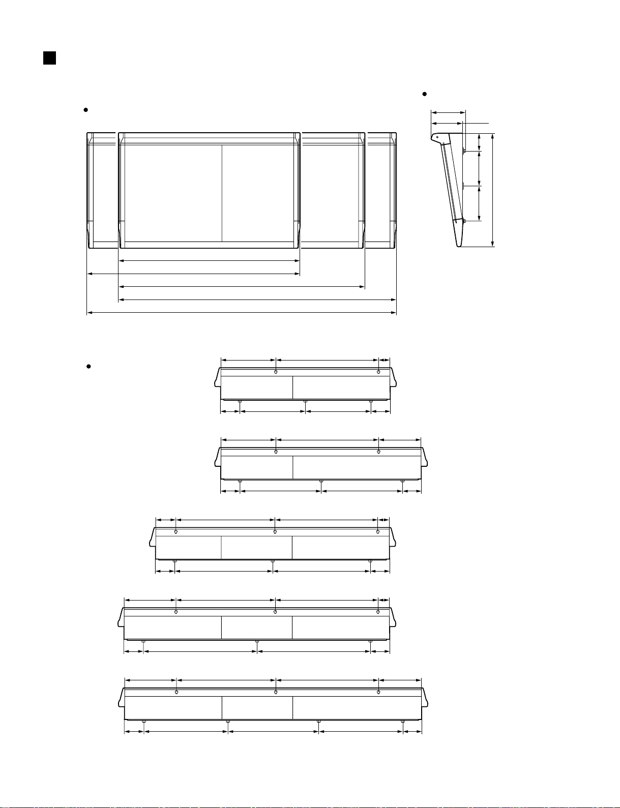
DIMENSIONS
Front
1400: M2500-24
1642: M2500-32
1899: M2500-40C
2142: M2500-48C
2385: M2500-56C
Side
265
23242
137270270
875
Rear
792422 88
55 55
55 55
55 55
55 55
847 847
968 968
597 597
792422 331
718 718
792768154 88
792768399 88
M2500-24
M2500-32
M2500-40C
M2500-48C
792768399 331
M2500-56C
55 55
8
740 740700
Units :mm
Page 7
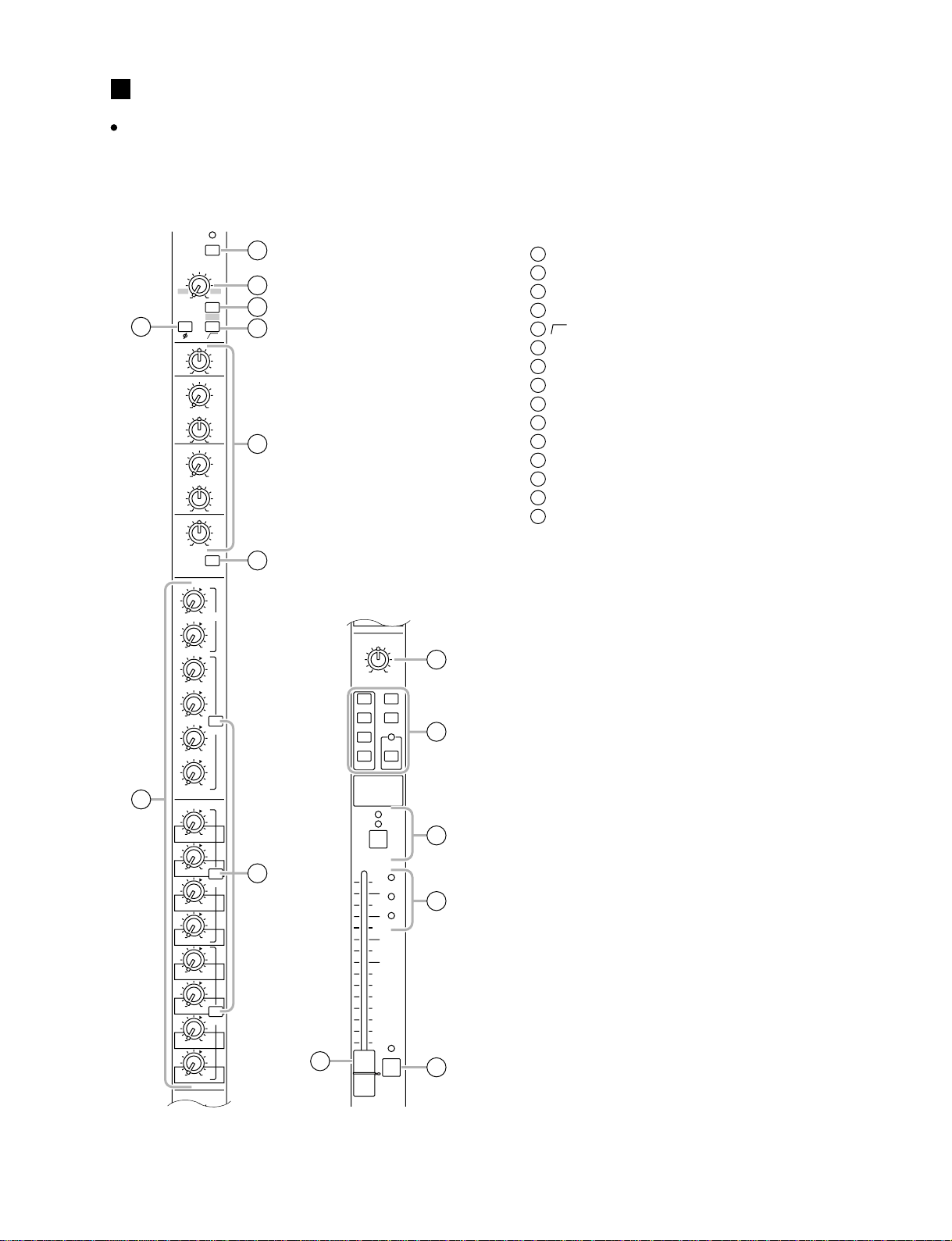
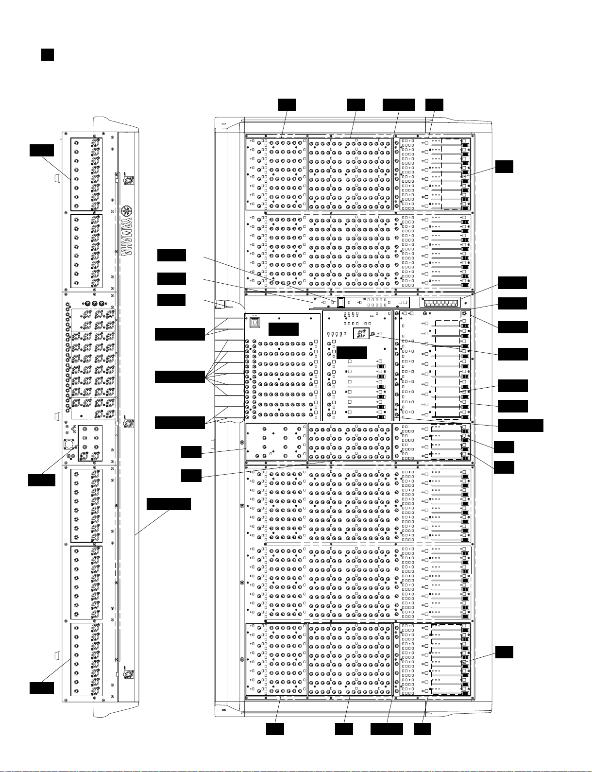
PANEL LAYOUT
Control panel
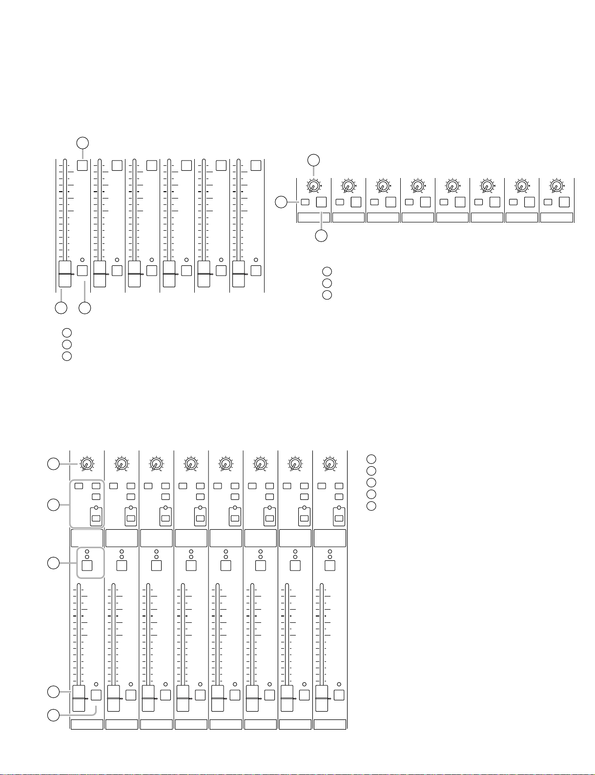
Input channel section
Monaural input channels
M2500
EQ
PRE
PRE
PRE
1
2
–34
3
5
80
6
7
010
AUX14
PAN
LCR
ODD EVEN
1-2
MONO
3-4
5-6
7-8
CHECK
ON
10
ST
11
LCR
12
ON/EDIT
9
14
10
PEAK
5
SIGNAL
0
5
10
20
30
40
50
60
NOM
PFL
13
15
+48V
GAIN
+10
–16 –60
26dB
4
HI
–15 +15
HI-MID
400 8k
–15 +15
LO-MID
80 1.6k
–15 +15
LO
–15 +15
010
AUX1 PRE
010
AUX2
010
AUX3
010
AUX4
010
AUX5
010
AUX6
8
010
AUX7
010
AUX8
010
AUX9
010
AUX10
010
AUX11
010
AUX12
010
AUX13
010
AUX14
PAN
C
+48 V (phantom power) switch
1
GAIN control
2
26 dB pad switch
3
φ
(phase) switch
4
(high pass filter) switch
5
80
EQ controls
6
EQ switch
7
AUX 1–AUX 14 controls
8
PRE switches
9
PAN control
10
Channel assign switches
11
ON/EDIT switch / ON, CHECK indicators
12
PEAK/NOM/SIGNAL indicators
13
Channel fader
14
PFL (pre-fader listen) switch
15
9
Page 8
M2500
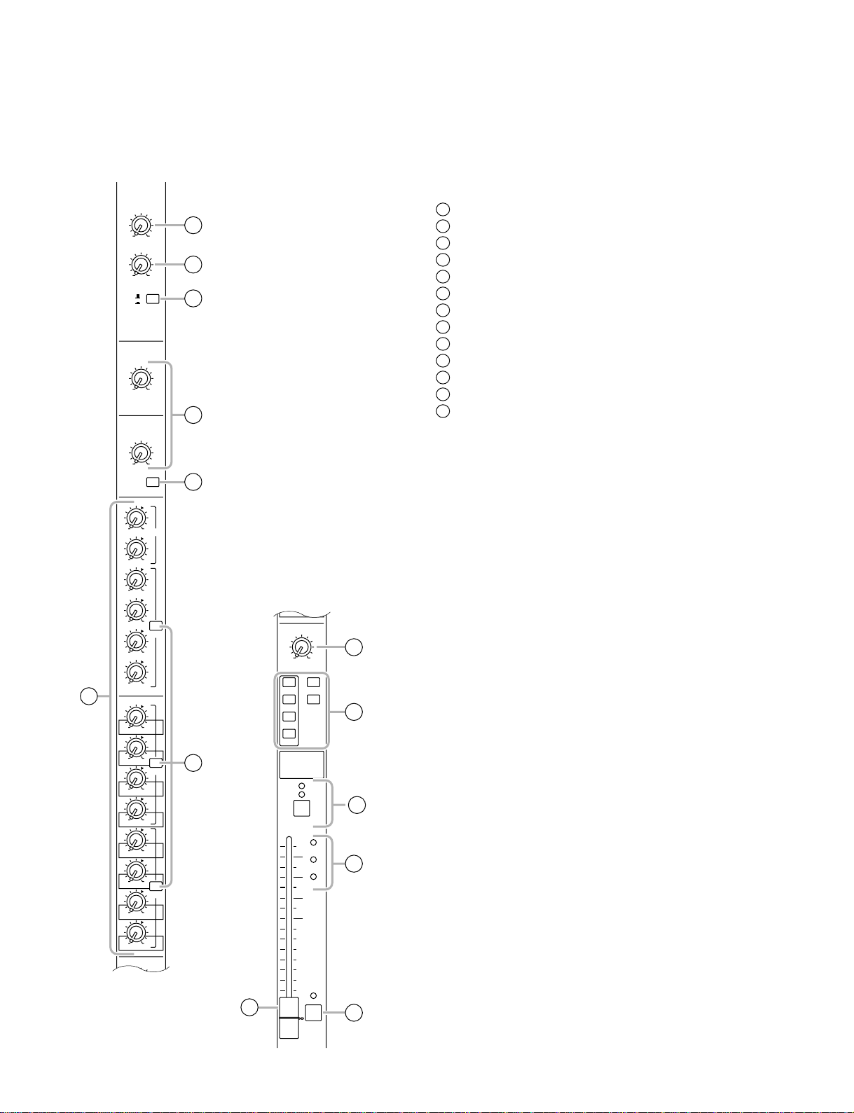
Stereo input channels
GAIN
A
+10 –30
B
+10 –20
HI
–15 +15
LO
GAIN A control
1
GAIN B control
1
2
A
B
3
4
2
A/B switch
3
EQ controls
4
EQ switch
5
AUX 1–AUX 14 controls
6
PRE switches
7
BAL control
8
Channel assign switches
9
ON/EDIT switch / ON, CHECK indicators
10
PEAK/NOM/SIGNAL indicators
11
Channel fader
12
PFL (pre-fader listen) switch
13
–15 +15
5
EQ
010
AUX1 PRE
010
AUX2
010
AUX3
010
010
AUX4
PRE
010
AUX5
010
AUX6
6
010
AUX7
010
AUX8
010
AUX9
010
AUX10
010
AUX11
010
AUX12
010
AUX13
010
AUX14
BAL
LCR
ODD EVEN
PRE
PRE
7
12
AUX14
BAL
LR
ODD EVEN
1-2
3-4
5-6
7-8
ON/EDIT
10
5
SIGNAL
0
5
10
20
30
40
50
60
ST
MONO
CHECK
ON
PEAK
NOM
PFL
8
9
10
11
13
10
Page 9
M2500
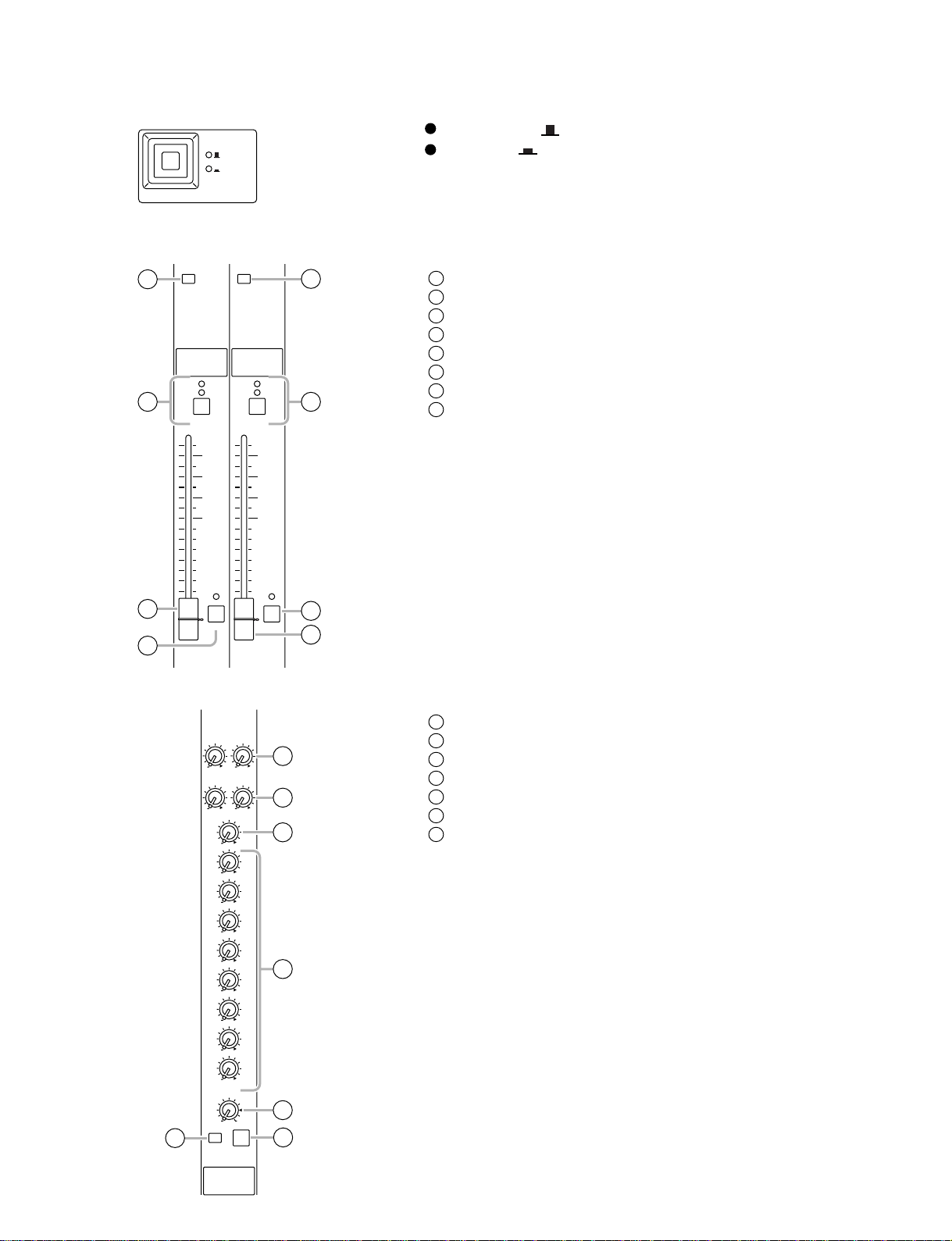
GROUP/AUX master section
AUX 1-6 section
1
10
5
0
5
10
20
30
40
50
60
AUX1
2
ON switches
1
AUX 1–6 master faders
2
AFL (after fader listen) switches
3
10
ON
5
0
5
10
20
30
40
50
60
AFL
AUX2
10
ON
5
0
5
10
20
30
40
50
60
AFL
AUX3
10
ON
5
0
5
10
20
30
40
50
60
AFL
AUX4
3
A7/G1-A14/G8 section
10
ON
5
0
5
10
20
30
40
50
60
AFL
AUX5
10
ON
AFL
ON
5
0
5
10
20
30
40
50
60
2
AFL
AUX6
1
010
LEVEL
ON
AFL
A7 / G1
010
LEVEL
ON
AFL
A8 / G2
3
LEVEL control
1
ON switch
2
AFL switch
3
010
LEVEL
ON
AFL
A9 / G3
010
LEVEL
ON
AFL
A10 / G4
010
LEVEL
ON
AFL
A11 / G5
010
LEVEL
ON
AFL
A12 / G6
010
LEVEL
ON
AFL
A13 / G7
010
LEVEL
ON
AFL
A14 / G8
G1/A7-G8/A14 section
PAN
4
MATRIX ST
5
6
7
8
G1 / A7
LCR
ON/EDIT
10
5
0
5
10
20
30
40
50
60
MONO
LCR
CHECK
ON
AFL
PAN
LCR
MATRIX ST
MONO
CHECK
ON
ON/EDIT
10
5
0
5
10
20
30
40
50
60
G2 / A8
LCR
AFL
PAN
LCR
MATRIX ST
MONO
CHECK
ON
ON/EDIT
10
5
0
5
10
20
30
40
50
60
G3 / A9
LCR
AFL
PAN
LCR
MATRIX ST
MONO
CHECK
ON
ON/EDIT
10
5
0
5
10
20
30
40
50
60
G4 / A10
LCR
AFL
PAN
LCR
MATRIX ST
MONO
CHECK
ON
ON/EDIT
10
5
0
5
10
20
30
40
50
60
G5 / A11
LCR
AFL
PAN
LCR
MATRIX ST
MONO
CHECK
ON
ON/EDIT
10
5
0
5
10
20
30
40
50
60
G6 / A12
LCR
AFL
PAN
LCR
MATRIX ST
MONO
CHECK
ON
ON/EDIT
10
5
0
5
10
20
30
40
50
60
G7 / A13
LCR
AFL
PAN
LCR
MATRIX ST
MONO
CHECK
ON
ON/EDIT
10
5
0
5
10
20
30
40
50
60
G8 / A14
LCR
AFL
PAN control
4
Channel assign switches
5
ON/EDIT switch / ON, CHECK indicators
6
Fader
7
AFL (after fader listen) switch
8
11
Page 10
M2500
GROUP/AUX FLIP switch
GROUP
AUX
GROUP/AUX FLIP
Stereo/monaural master section
STEREO section MONO/C section
1
2
MATRIX MATRIX
CHECK
ON
CHECK
ON
ON/EDITON/EDIT
5
6
When GROUP ( ) is selected
When AUX ( ) is selected
MATRIX switch
1
ON/EDIT switch / ON, CHECK indicators
2
Fader
3
AFL switch
4
MATRIX switch
5
ON/EDIT switch / ON, CHECK indicators
6
Fader
7
AFL switch
8
10
5
0
5
10
20
30
40
50
3
60
4
Matrix section
AFL
SUB IN
ST
0
MONO/C
0
G1 / A7
0
G2 / A8
0
G3 / A9
0
G4 / A10
0
G5 / A11
0
G6 / A12
0
G7 / A13
0
G8 / A14
10
5
0
5
10
20
30
40
50
60
8
AFL
7
MONO/CSTEREO
SUB IN L/R control
1
ST L/R controls
2
0L0
0L0
1
R
2
R
3
MONO/C control
3
G1/A7–G8/A14 controls
4
LEVEL control
5
ON switch
6
AFL switch
7
4
12
010
LEVEL
6
ON
MATRIX 1
5
7
AFL
Page 11
M2500
G1-8/A7-14
AUX1-6
A7-14/G1-8
MATRIX
METER
SELECT
1
2
3
4
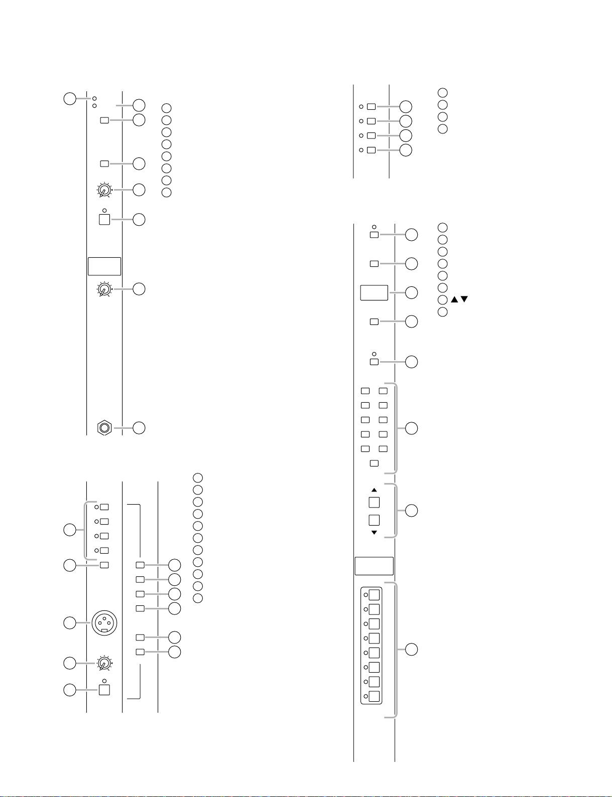
Monitor section
1
INPUT
MASTER
MASTER
PFL
L+R
010
LEVEL
ON
MONITOR
010
PHONES
Meter select section
MATRIX switch
1
A7-14/G1-8 switch
2
3
4
5
INPUT indicator
1
MASTER indicator
2
MASTER PFL switch
3
L+R switch
4
LEVEL control
5
ON switch
6
PHONES (headphone) control
7
PHONES jack
8
2
AUX 1-6 switch
3
G1-8/A7-14 switch
4
Control section
6
UTILITY
RECALL
7
MEMORY
STORE
CHECK
1
2
3
4
5
UTILITY switch
1
RECALL switch
2
MEMORY display
3
STORE switch
4
CHECK switch
5
0–9/ENTER switches
6
/ switches
7
DIRECT RECALL 1–8 switches
8
8
Talkback/oscillator section
PINK
1
2
10kHz
1kHz
100Hz
ON
OSCILLATOR
AUX1-2
AUX3-6
AUX7-10
AUX11-14
3
ST
MONO/C
4
5
MIC
010
TB/OSC
ON
TALKBACK
6
7
8
9
10
11
OSCILLATOR select switches
1
OSCILLATOR ON switch
2
MIC jack
3
TB/OSC control
4
ON switch
5
AUX 1-2 switch
6
AUX 3-6 switch
7
AUX 7-10 switch
8
AUX 11-14 switch
9
ST switch
10
MONO/C switch
11
1 2
3 4
5 6
7 8
9
ENTER
SCENE
MEMORY
DIRECT
RECALL
CONTROL
6
0
7
1
2
3
4
8
5
6
7
8
13
Page 12
M2500
+
3
0
1
3
PEAK
V
7
10
20
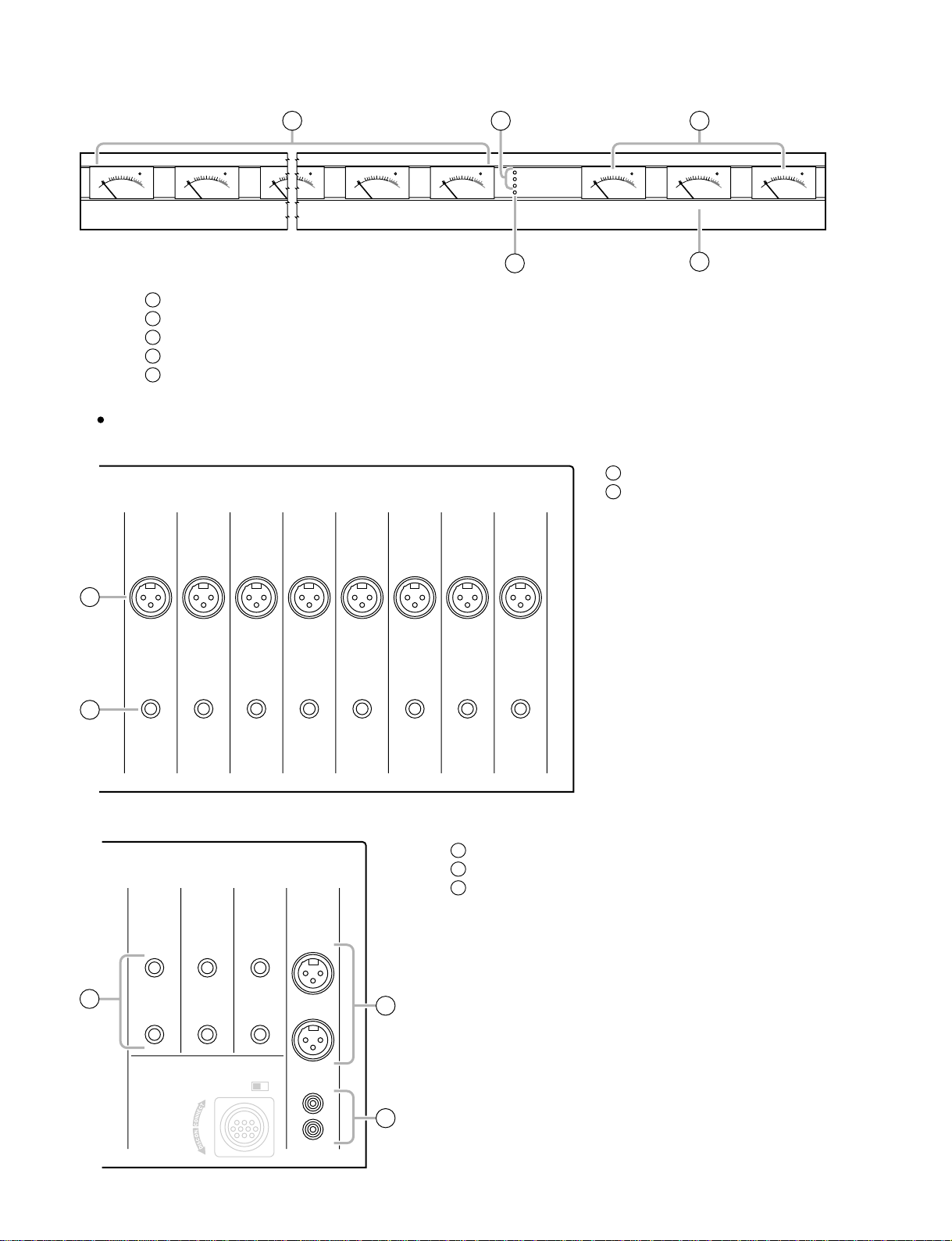
Meter bridge
PEAK
357
1
0
10
20
3
+
VU
1
2
3
4
5
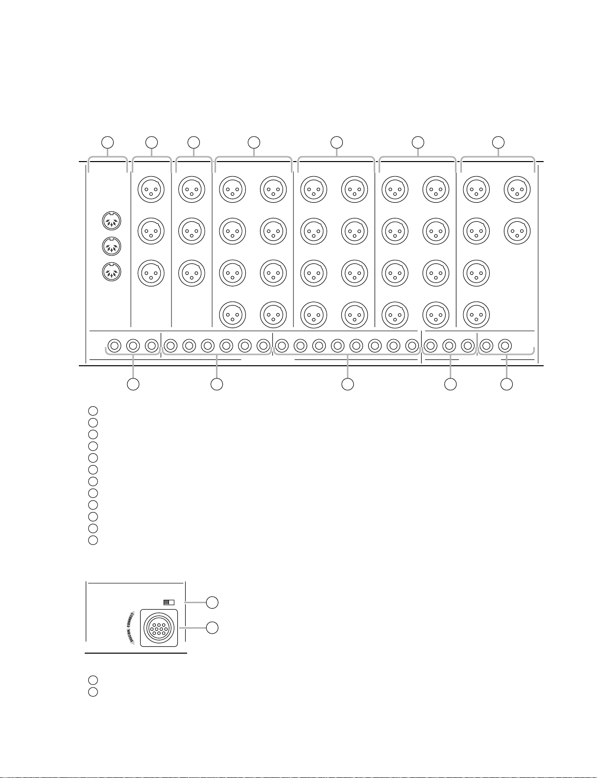
Rear panel
PEAK
357
1
0
10
20
3
+
VU
1/7–8/14 level meters
+15V/–15V/+12V indicators
PHANTOM MASTER indicator
STEREO, PFL/AFL level meters
MONO/C level meter
1 2 4
Monaural input channel input/output jacks
24
INPUT
23
INPUT
22
INPUT
21
INPUT
INPUT
–
10
20
STEREO R
PFL/AFL R
PEAK
357
1
0
3
+
VU
PEAK
357
1
0
10
20
3
+
VU
PEAK
357
10
20
VU
8/147/132/81/7
+15V
1
0
3
–15V
+12V
+
PHANTOM MASTER
20
10
PFL/AFL L
PEAK
357
1
0
3
+
VU
3
INPUT jacks
1
INSERT I/O jacks
2
20
19
INPUT
18
INPUT
17
INPUT
PEAK
357
1
0
10
20
3
+
VU
MONO/CSTEREO L
5
1
INSERT
I/O
I/O
INSERT
0
dB
INSERT
0
dB
I/O
INSERT
0
dB
I/O
INSERT
0
dB
2
Stereo input channel input/output jacks
INPUT
R
ST CH 1
INPUT A
L
R
ST CH 4
ST CH 3
INPUT
L/MONO
5
L/MONO
R
ST CH 2
INPUT
L/MONO
R
I/O
I/O
INSERT
0
dB
INSERT
0
dB
3
4
5
INSERT
I/O
I/O
0
0
dB
dB
INPUT A jacks
INPUT B jacks
INPUT jacks
3
PHANTOM
MASTER
OFF ON
INPUT B
L
4
READ OWNER’S MANUAL
R
DC POWER INPUT
14
Page 13
Master section input/output jacks
M2500
12
MIDI
IN
OUT
THRU
6 5 4 3
MONITOR
OUT
+4
dB
L
MONO
/C
R
ST OUT
+4
MONO
11 10
AUX OUT jacks
1
GRP/AUX OUT jacks
2
AUX/GRP OUT jacks
3
MATRIX OUT jacks
4
ST OUT, MONO/C OUT jacks
5
MONITOR OUT jacks
6
SUB IN MATRIX jacks
7
SUB IN ST L/R, MONO/C jack
8
INSERT I/O G1/A7–G8/A14 jacks
9
INSERT I/O AUX jacks
10
INSERT I/O ST L/R, MONO jacks
11
MIDI connectors
12
dB
L
/C
R
AUX
MATRIX OUT
123456
INSERT I/O
2 1
+4
dB
15
26
37
48
+4
dB
AUX/GRP OUT
A11/
G6
A12/
G6
A13/
G7
A14/
G8
+4
dB
A7/
G1
A8/
G2
A9/
G3
A10/
G4
GRP/AUX OUT
G5/
A11
G6/
A12
G7/
A13
G8/
A14
+4
dB
G1/
A7
G2/
A8
G3/
A9
G4/
A10
AUX OUT
ST LMONO/CST RST LMONO/CST R G1/A7G2/A8G3/A9G4/A10G5/A11G6/A12G7/A13G8/A14
SUB IN
+4
dB
13
24
5
6
MATRIX
LR
+4
dB
9 8 7
PHANTOM
MASTER
OFF ON
READ OWNER’S MANUAL
PHANTOM MASTER switch
13
DC POWER INPUT connector
14
DC POWER INPUT
13
14
15
Page 14
M2500
INJK
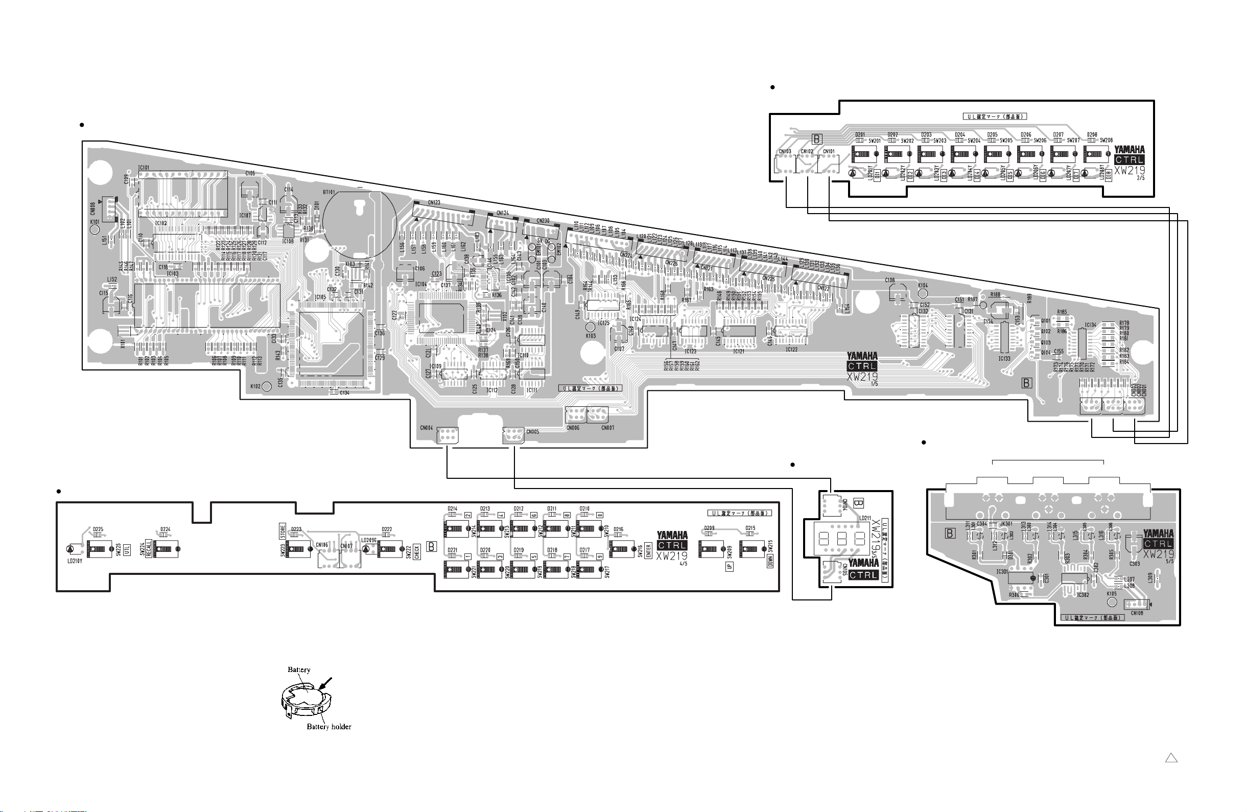
CIRCUIT BOARD LAYOUT
IN1 IN3IN2 INPAN
IN4
CTRL 3/5
STJK
CTRL 4/5
CTRL 5/5
MASOUT3
MASOUT4
MASOUT1
MASOUT
ST1
ST2
MAS1
MAS2 1/2
CTRL 2/5
CTRL 1/5
MAS3 2/2
MAS2 2/2
MAS4
MAS3 1/2
MASPAN
ST4
ST3
INJK
16
IN1 IN2 INPAN IN3
IN4
56CH
Page 15
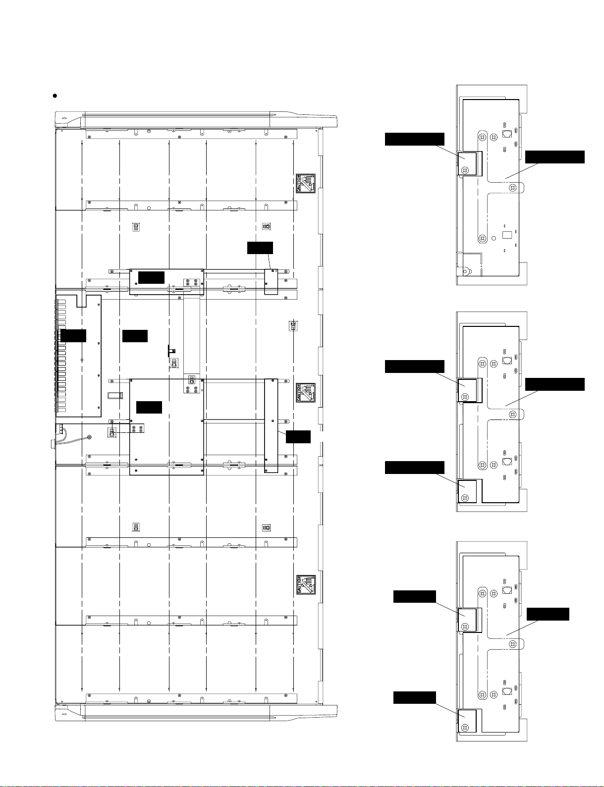
M2500-56C
ISRT 3/6
ISRT 5/6
METER2 2/2
2/3
M2500
METER2 2/2
1/3
ISRT 1/6
ISRT 6/6
ISRT 2/6
ISRT 4/6
METER2 1/2
2/3
METER2 1/2
3/3
METER1
2/3
METER2 1/2
1/3
METER1
1/3
METER1
3/3
17
Page 16
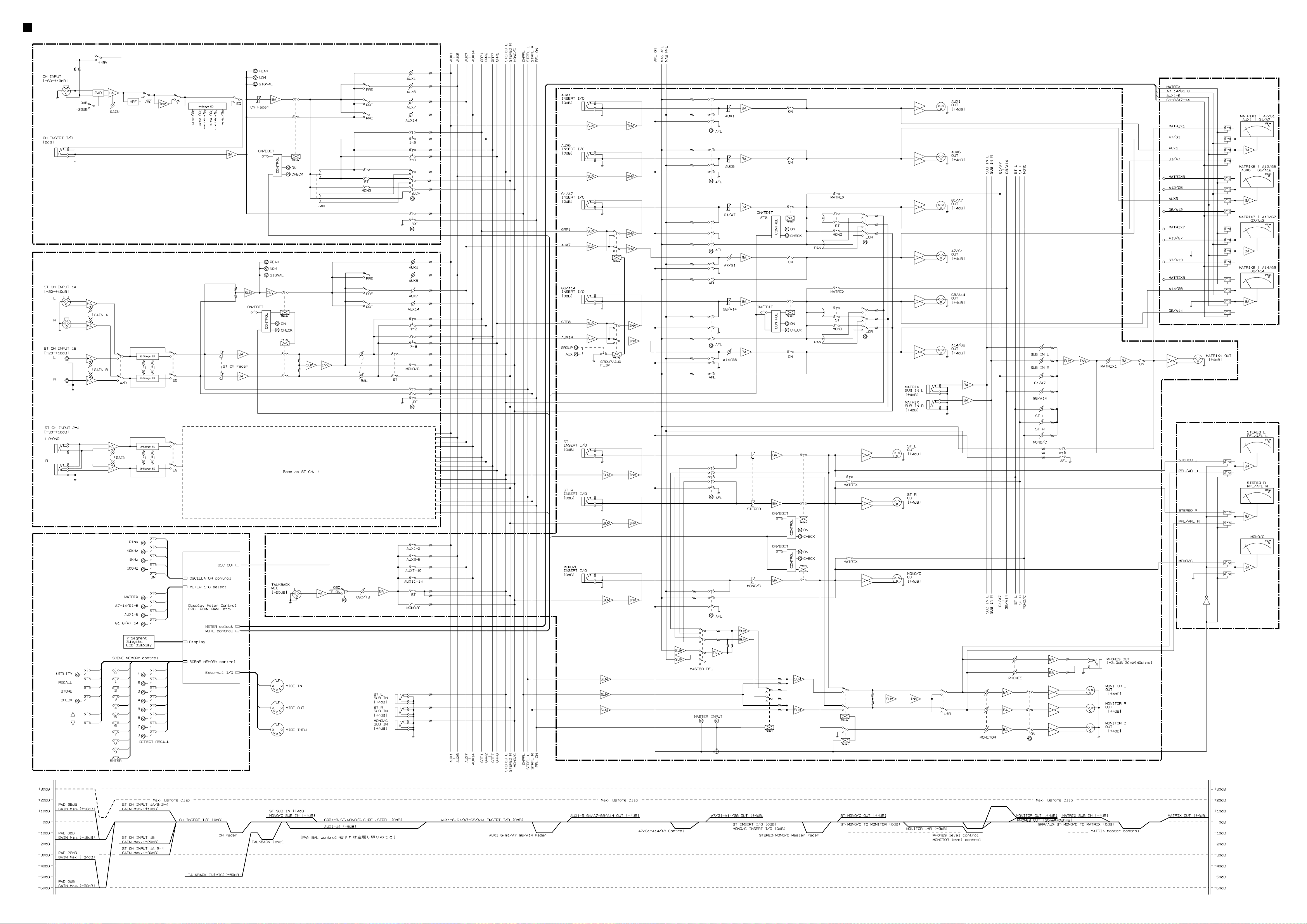
<P.2>M2500 BLOCK & LEVEL DIAGRAM
CH INPUT(IN
INPUT(ST
)
)
MASTER(MAS
)
METER
CONTROL
METER
Page 17

CIRCUIT BOARDS
CONTENTS
MASOUT1 Circuit Board ......................................34
MASOUT2 Circuit Board.......................................35
MASOUT3 Circuit Board.......................................36
METER1 Circuit Board .........................................37
METER2 Circuit Board .........................................37
METER3 Circuit Board .........................................37
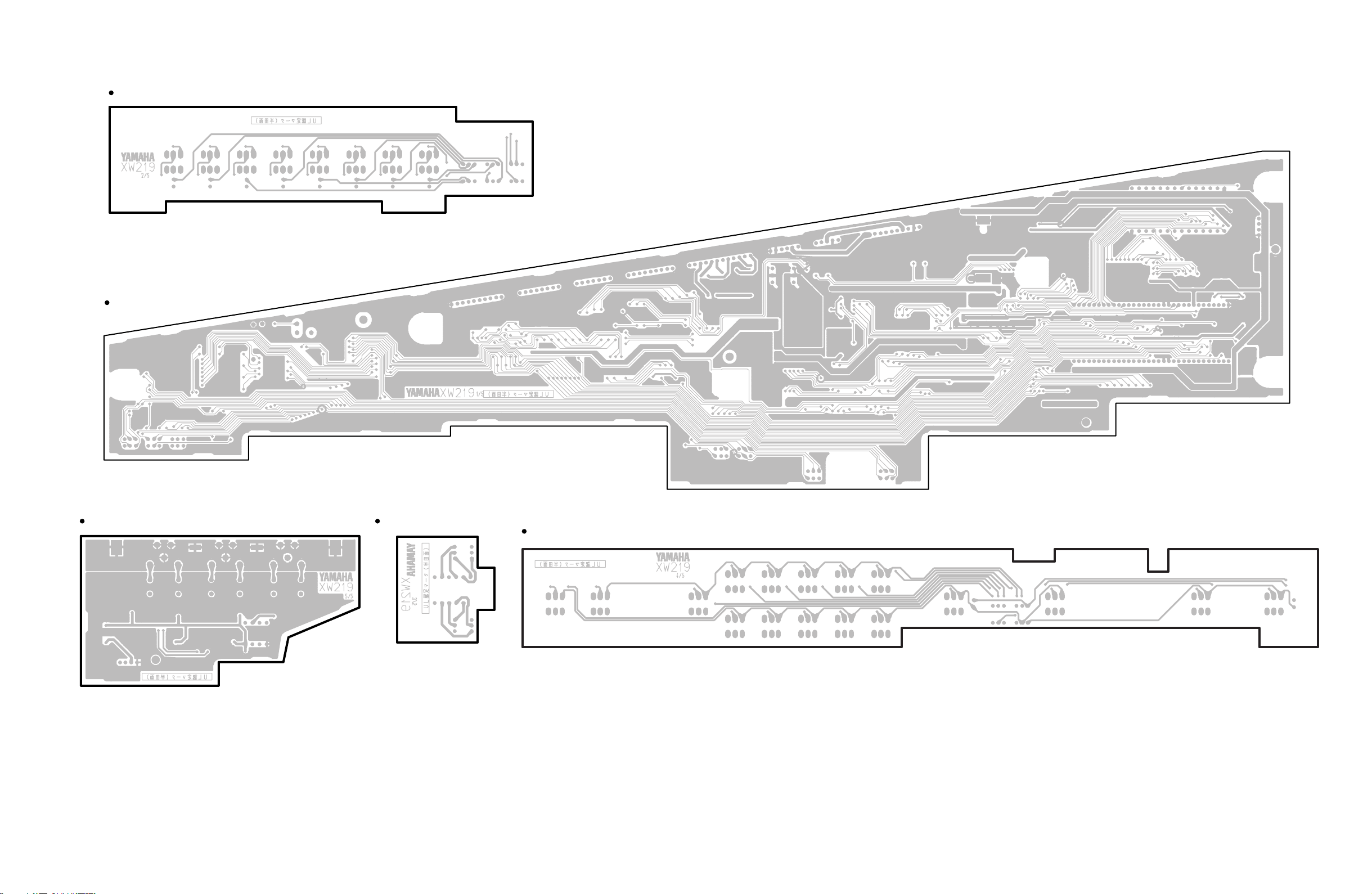
CTRL 1/5 Circuit Board ........................................38
CTRL 2/5 Circuit Board ........................................38
CTRL 3/5 Circuit Board ........................................38
CTRL 4/5 Circuit Board ........................................38
CTRL 5/5 Circuit Board ........................................38
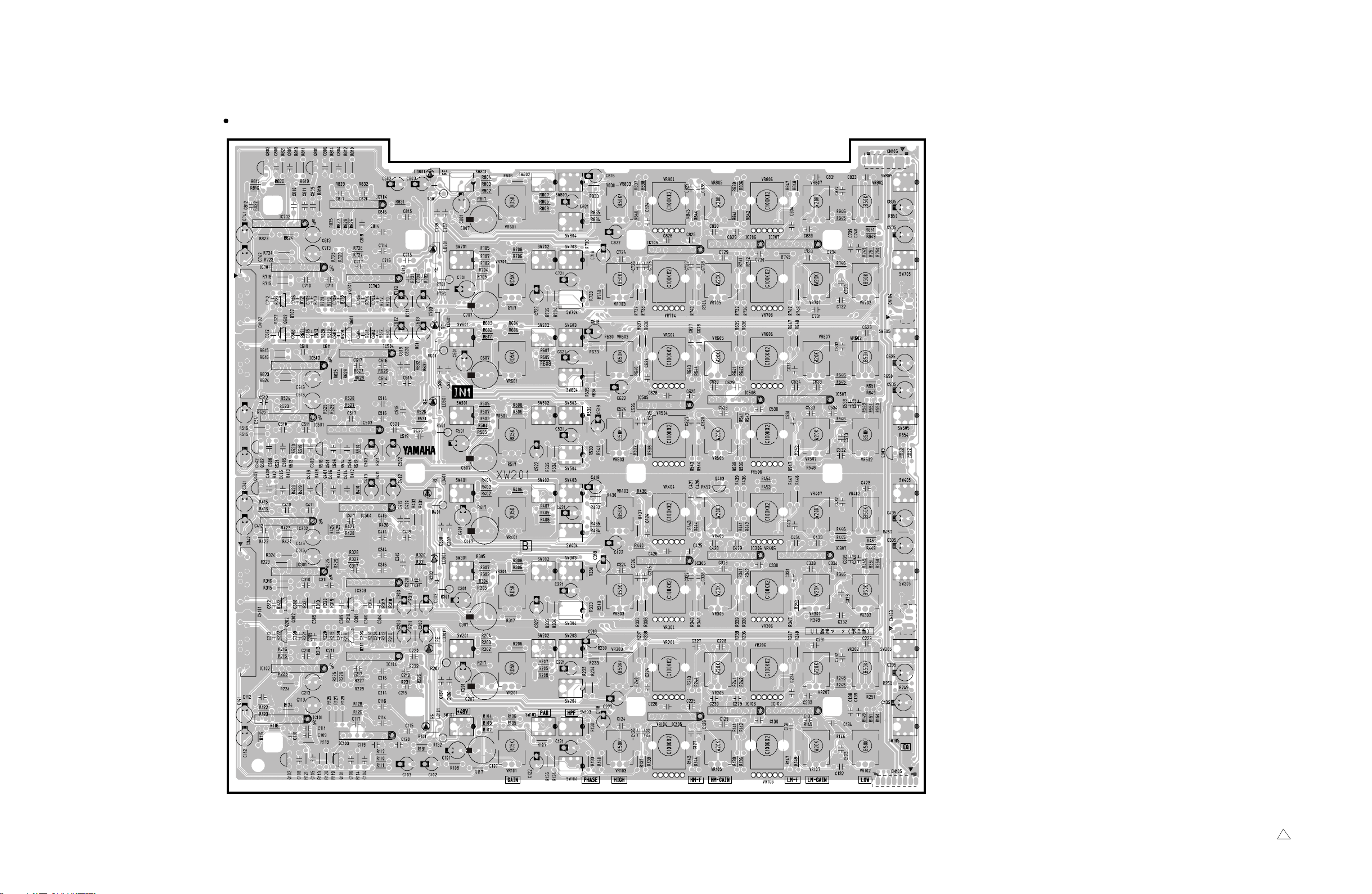
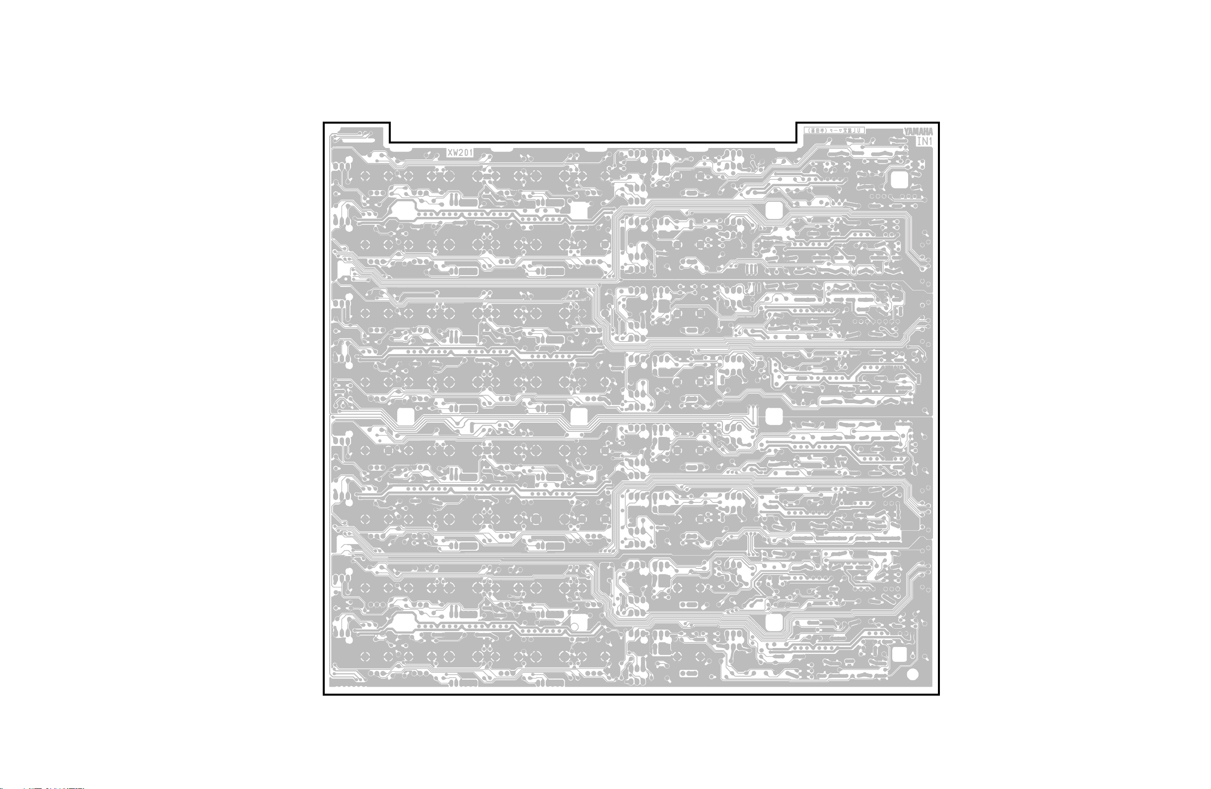
IN1 Circuit Board ..................................................40
IN2 Circuit Board ..................................................42
IN3 Circuit Board ..................................................44
IN4 Circuit Board ..................................................46
IN JK Circuit Board ...............................................47
IN PAN Circuit Board ............................................47
ISRT 1/6 Circuit Board ..........................................48
ISRT 2/6 Circuit Board ..........................................49
ISRT 3/6 Circuit Board ..........................................49
ISRT 4/6 Circuit Board ..........................................48
ISRT 5/6 Circuit Board ..........................................48
ISRT 6/6 Circuit Board ..........................................48
MAS1 1/2 Circuit Board ........................................48
MAS1 2/2 Circuit Board ........................................48
MAS2 1/2 Circuit Board ........................................52
MAS2 2/2 Circuit Board ........................................52
MAS3 1/2 Circuit Board ........................................54
MAS3 2/2 Circuit Board ........................................54
MAS4 Circuit Board ..............................................56
MAS PAN Circuit Board ........................................56
ST1 Circuit Board .................................................57
ST2 Circuit Board .................................................58
ST3 Circuit Board .................................................59
ST4 Circuit Board .................................................60
STJK 1/2 Circuit Board .........................................60
STJK 2/2 Circuit Board .........................................60
M2500
Note : See parts list for details of circuit board component parts.
33
Page 18
M2500
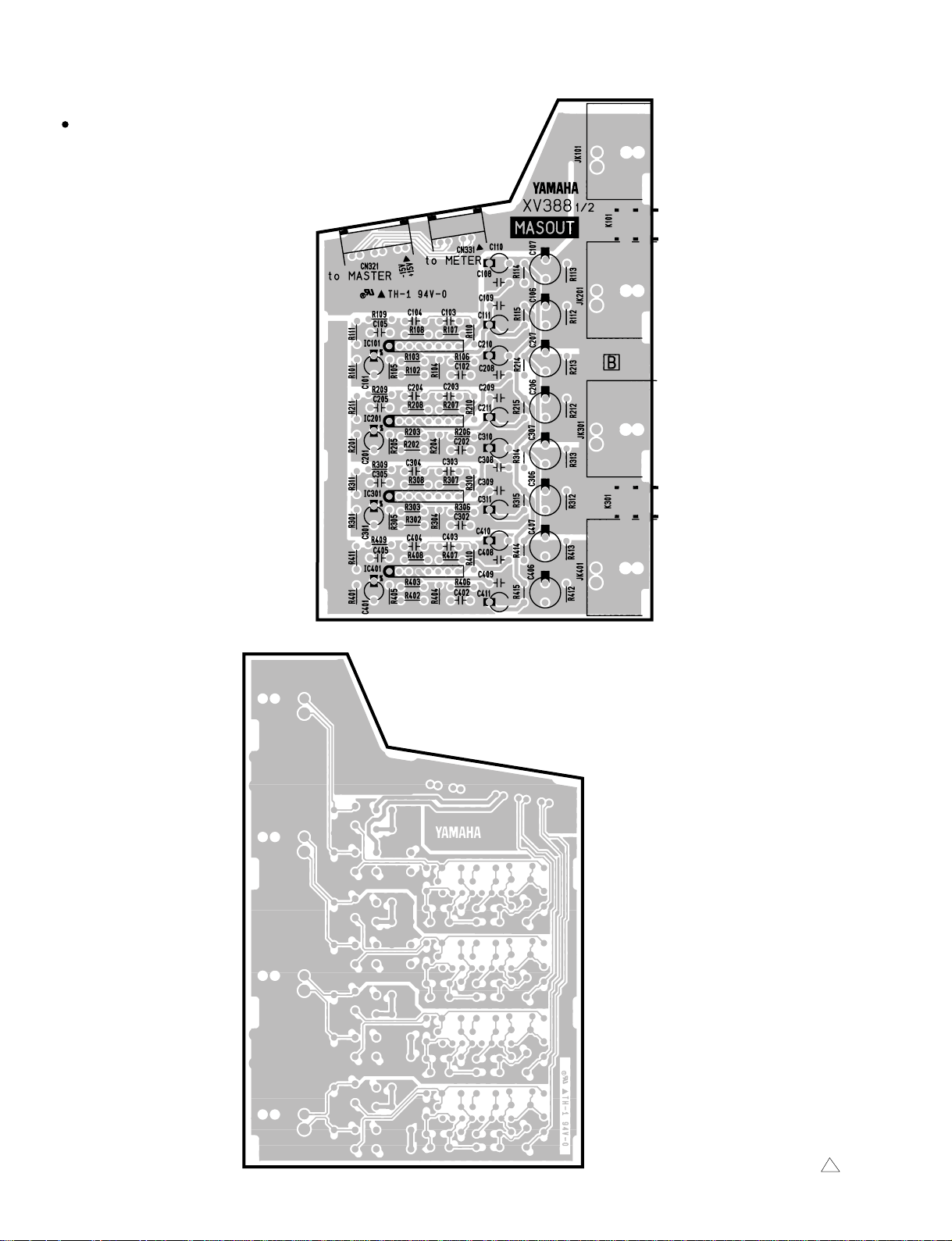
MASOUT1 Circuit Board
to METER1
-CN104
MATRIX OUT (5, 1)
AUX/GRP OUT (A11/G6, A7/G1)
GRP/AUX OUT (G5/A11, G1/A7)
AUX OUT (3)
CN321:
(AUX OUT 326)
MAS2-CN205
(AUX/GRP OUT A7/G1~A10/G4)
MAS2-CN206
(AUX/GRP OUT A11/G5~A14/G8)
MAS2-CN207
(GRP/AUX OUT G1/A7~G4/A10)
MAS3-CN308
(GRP/AUX OUT G5/A11~G8/A14)
MAS3-CN309
(MATRIX OUT 1~4)
MAS1-CN101
(MATRIX OUT 5~8)
MAS1-CN102
MATRIX OUT (6, 2)
AUX/GRP OUT (A12/G6, A8/G2)
GRP/AUX OUT (G6/A12, G2/A8)
AUX OUT (4)
MATRIX OUT (7, 3)
AUX/GRP OUT (A13/G7, A9/G3)
GRP/AUX OUT (G7/A13, G3/A9)
AUX OUT (5)
MATRIX OUT (8, 4)
AUX/GRP OUT (A14/G8, A10/G4)
GRP/AUX OUT (G8/A14, G4/A10)
AUX OUT (6)
Component side
34
Pattern side
MASOUT1 : 3NA-V230710 1
Page 19
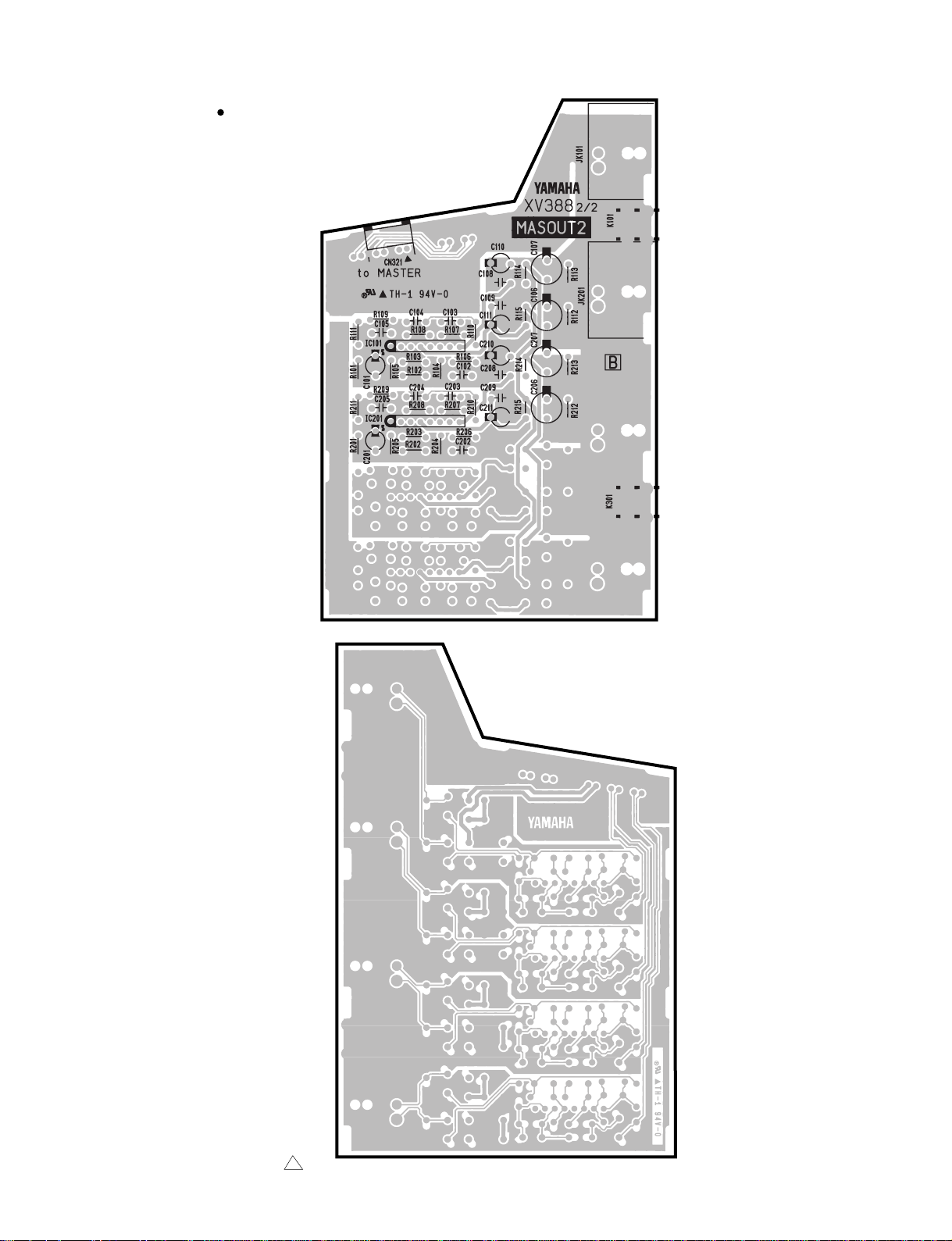
MASOUT2 Circuit Board
to MAS2
-CN204
M2500
AUX OUT
1
AUX OUT
2
Component side
MASOUT2 : 3NA-V230710 1
Pattern side
35
Page 20
M2500
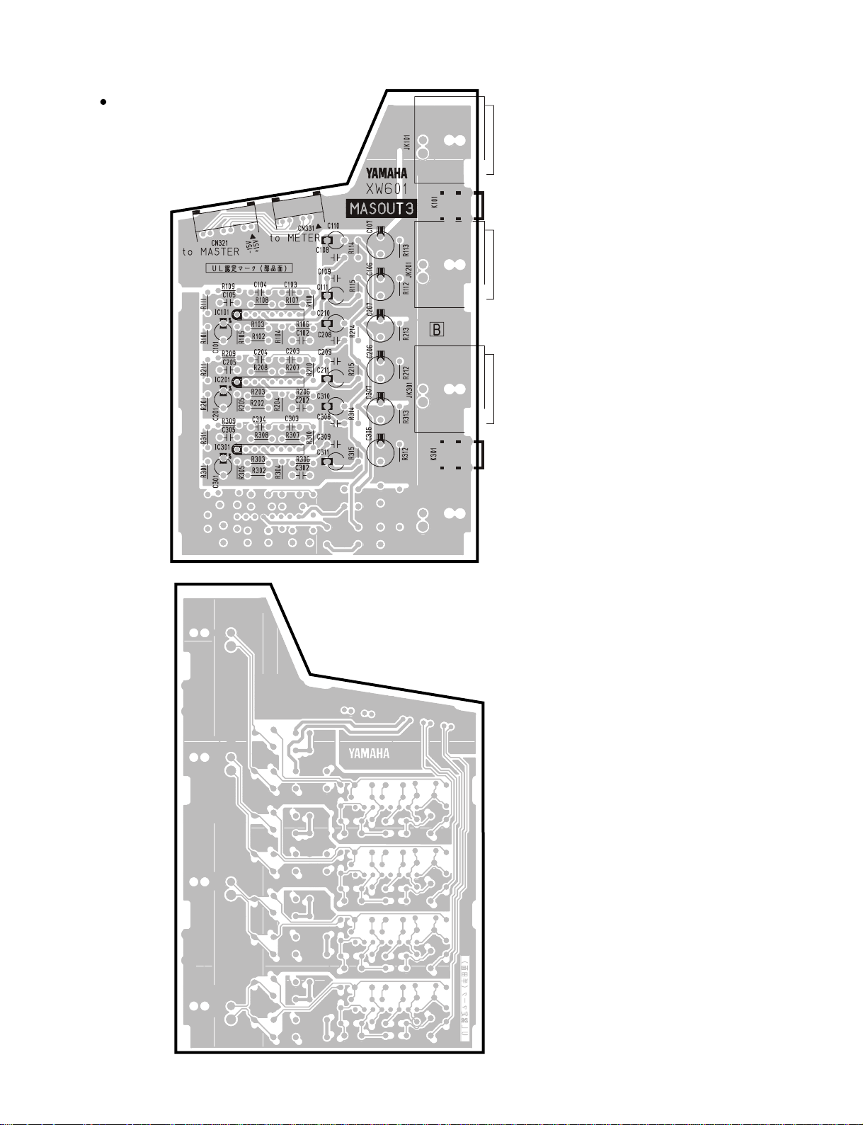
MASOUT3 Circuit Board
to MAS3-CN310 (ST OUT)
to MAS3-CN321 (MON1)
MONITOR OUT (L)
ST OUT (L)
to METER 2-1, 2-2-CN104
MONITOR OUT (MONO/C)
ST OUT (MONO/C)
MONITOR OUT (R)
ST OUT (R)
Component side
36
Pattern side
MASOUT3 : 3NA-V431500
Page 21
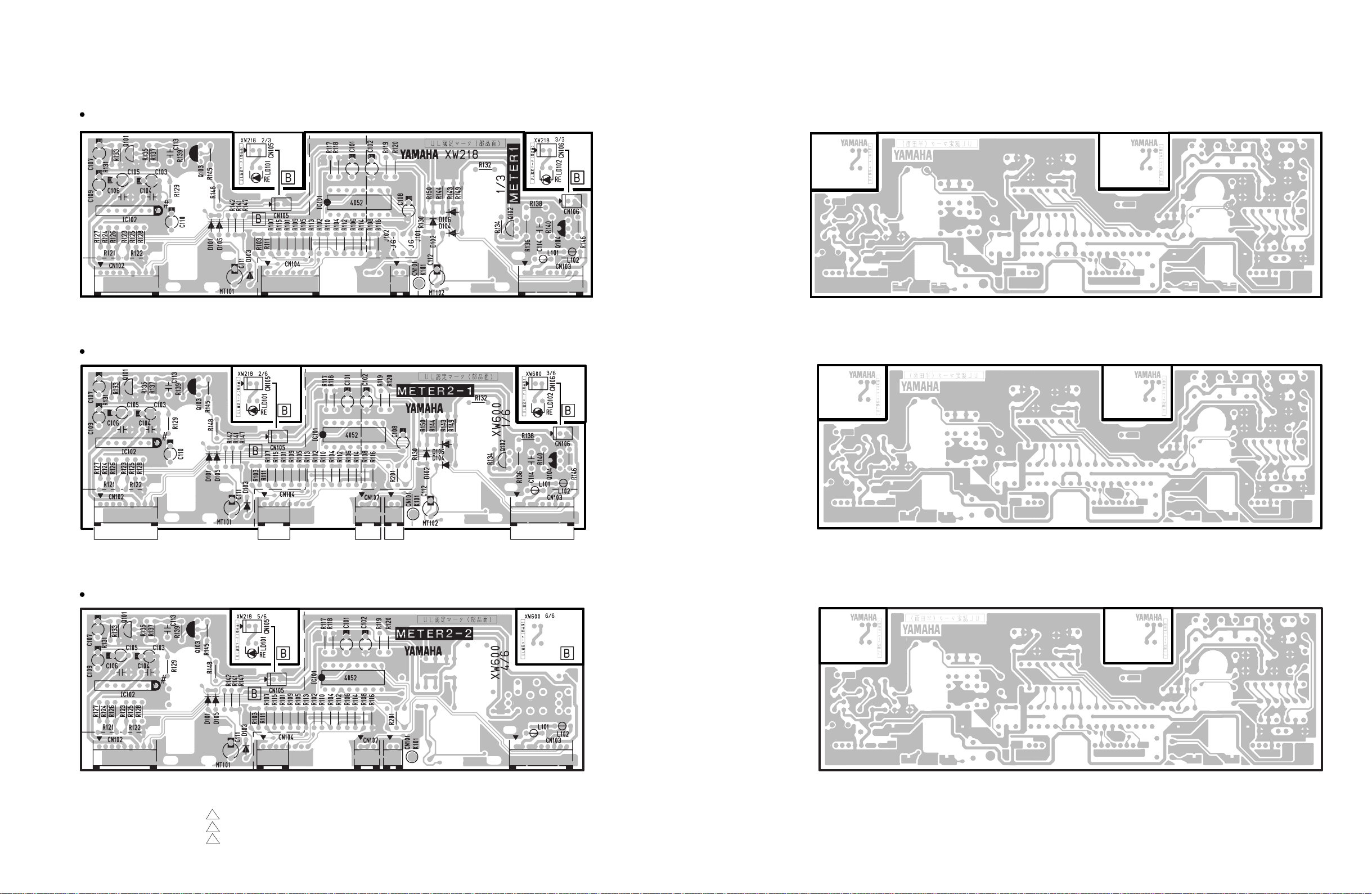
METER1 Circuit Board
M2500
to METER
METER2-1 Circuit Board
to METER
NC
METER2-2 Circuit Board
MASOUT2-CN331
to MASOUT3
-CN331
to GOOSE NECKto MASOUT1
to ISRT
& METER
to GOOSE
NECK
to INSERT
to METER
Component side
Component side
Pattern side
Pattern side
to METER
NC
METER1: 3NA-V431480 2
METER2-1: 3NA-V431490 1
METER2-2: 3NA-V431490 1
to MASOUT3
-CN331
to ISRT
& METER
to GOOSE
& NECK
Component side
Pattern side
37
Page 22
M2500
CTRL Circuit Board 1/5
CTRL Circuit Board 2/5
to CTRL5/5
-CN108
to MAS 2
-CN209
to MAS 2
-CN210
to ISRT
-CN409 to ISRT
to CTRL4/5
-CN106
-CN405
to CTRL4/5
-CN107
to ISRT
-CN406
N.C.
to ISRT
-CN404
N.C.
Component side
CTRL Circuit Board 3/5
Component side
CTRL Circuit Board 5/5
IN OUT THRU
MIDI
38
CTRL Circuit Board 4/5
Battery VN103500
VN103600(Battery holder for VN103500)
• Notice for back-up battery removal
Push the battery as shows in figure,
then the battery will pop up.
• Druk de batterij naar beneden zoals
aangeven in de tekening, de batterij
springt dan naar voren.
to CTRL1/5
-CN006
to CTRL1/5
-CN007
Component side
Component side
to CTRL1/5
-CN108
Component side
CTRL: 3NA-V431460 3
Page 23
CTRL Circuit Board 2/5
CTRL Circuit Board 1/5
M2500
Pattern side
CTRL Circuit Board 5/5
Pattern side
CTRL Circuit Board 3/5
Pattern side
CTRL Circuit Board 4/5
Pattern side
Pattern side
39
Page 24
M2500
to INJK-CN602
IN1 Circuit Board
to IN1-CN105
ISRT-CN212
NC
to IN2
-CN202
40
to INJK-CN601
to IN2
-CN201
to IN2-CN106
ISRT-CN314
NC
Component side
3NA-V431320 1
Page 25
M2500
Pattern side
41
Page 26
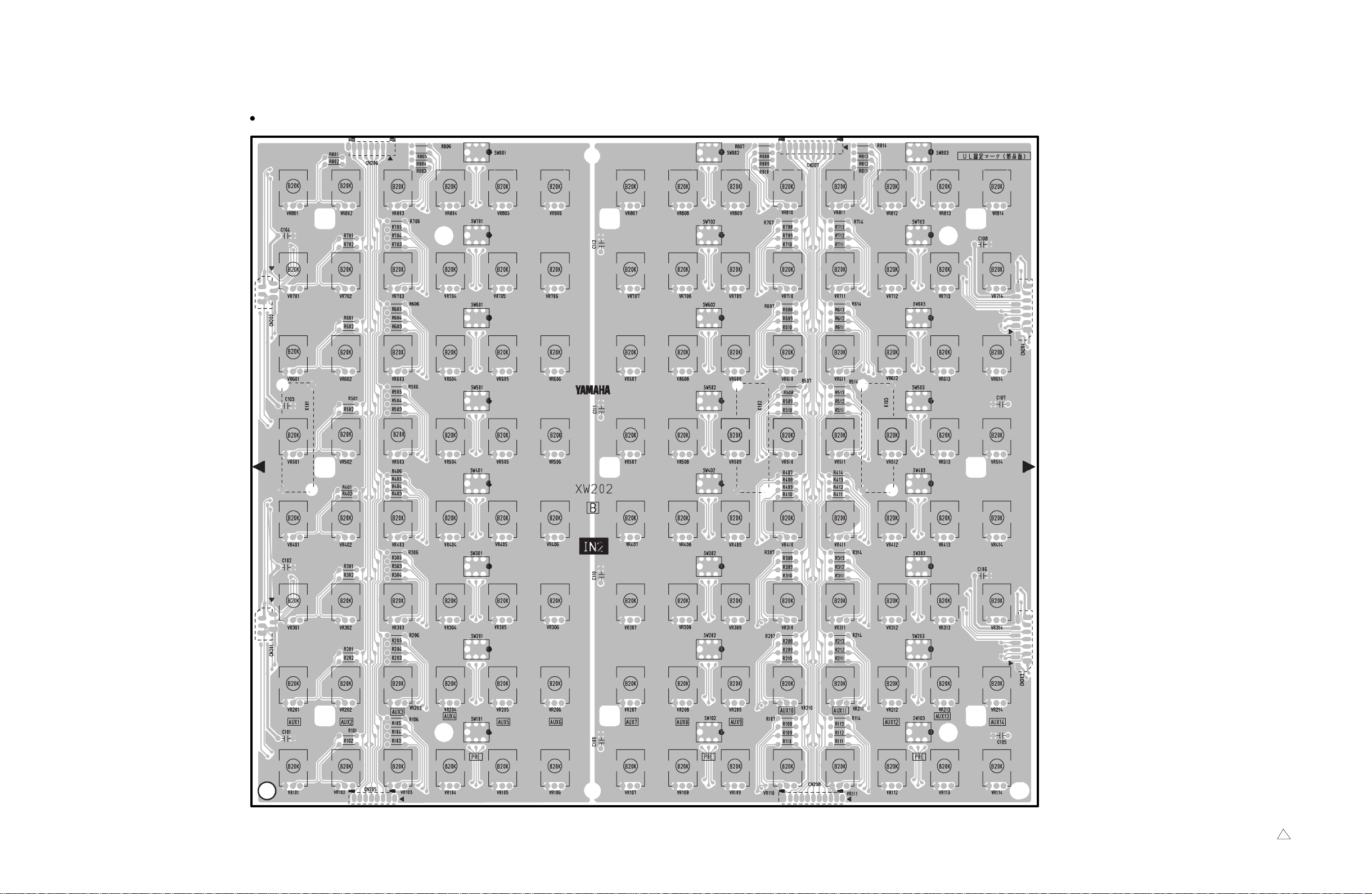
M2500
to IN1
-CN104
IN2 Circuit Board
to IN2-CN208
ISRT-CN203, 205
NC
to IN3
-CN302
42
to IN1
-CN103
to IN2-CN206
ISRT-CN301
NC
to IN2-CN207
ISRT-CN303, 305
NC
to IN3
-CN301
Component side
3NA-V431330 1
Page 27
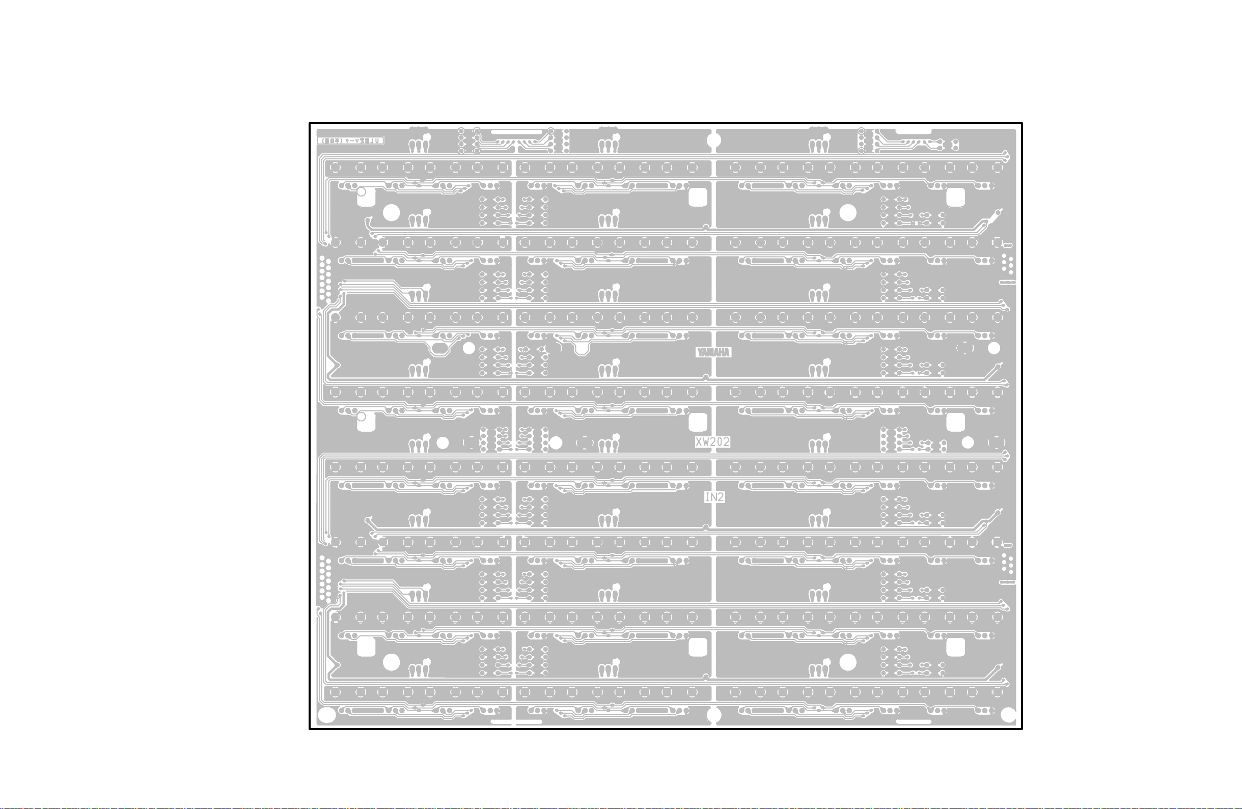
M2500
Pattern side
43
Page 28
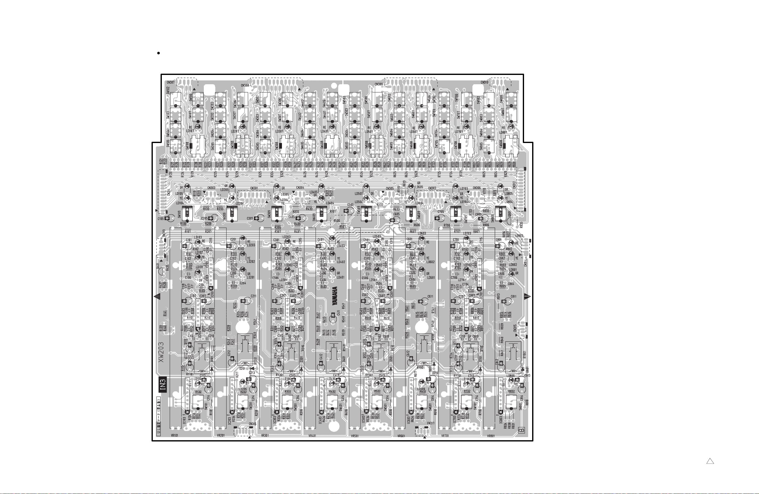
M2500
IN3 Circuit Board
to INPAN-CN501 to INPAN-CN502 to INPAN-CN503 to INPAN-CN504
to IN3-CN312
ISRT-CN306, 308
NC
CN303: to IN4-CN401
CN301: to IN2-CN203
CN304: to IN4-CN402
to IN3-CN314
ISRT-CN313
NC
to IN3-CN311
ISRT-CN206, 208
NC
CN305: to IN4-CN403
CN302: to IN2-CN204
CN306: to IN4-CN404
to IN3-CN313
ISRT-CN213
NC
to IN4-CN405
44
to IN4-CN408 to IN4-CN409
Component side
3NA-V431350 1
Page 29
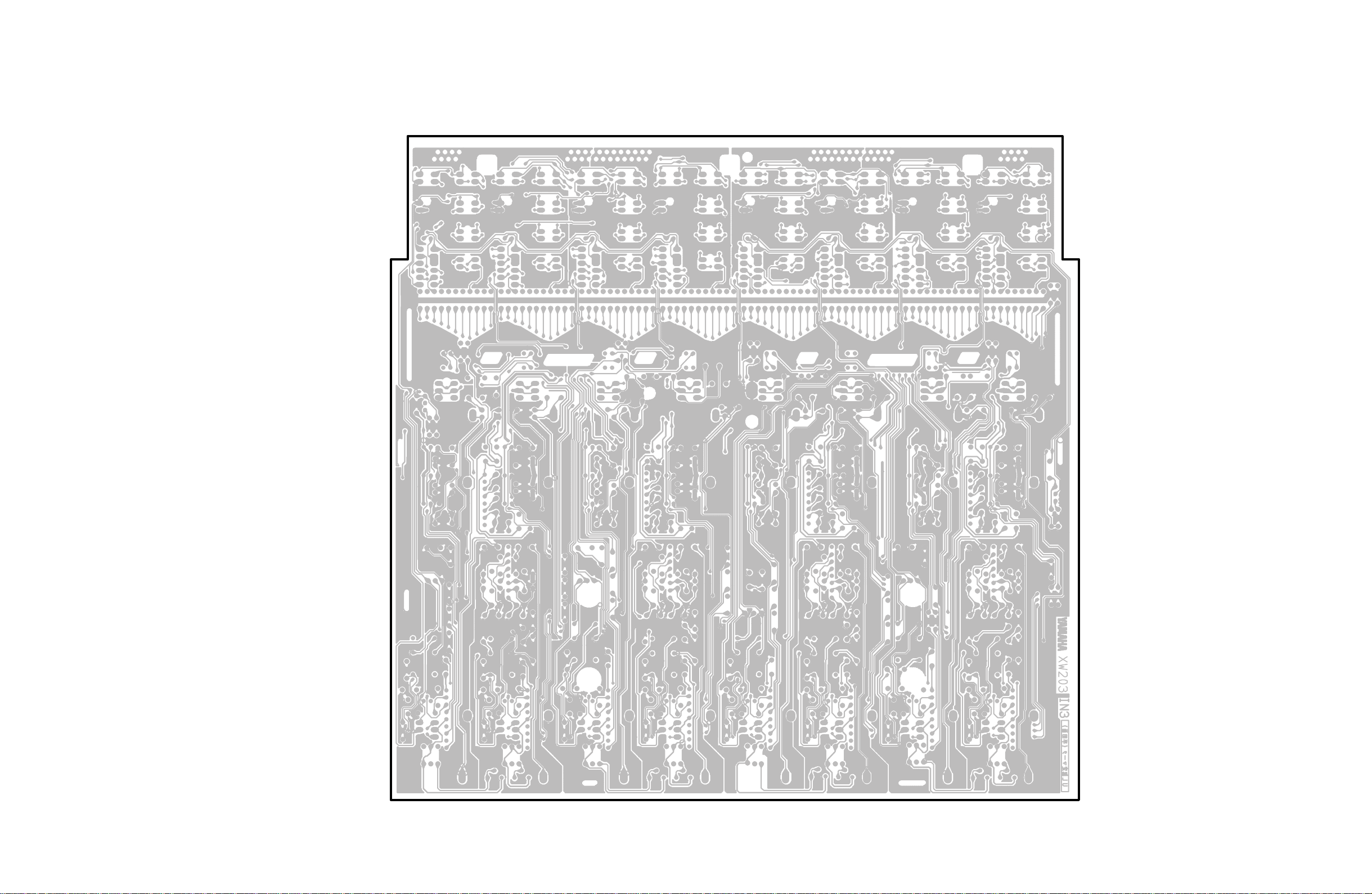
M2500
Pattern side
45
Page 30
M2500
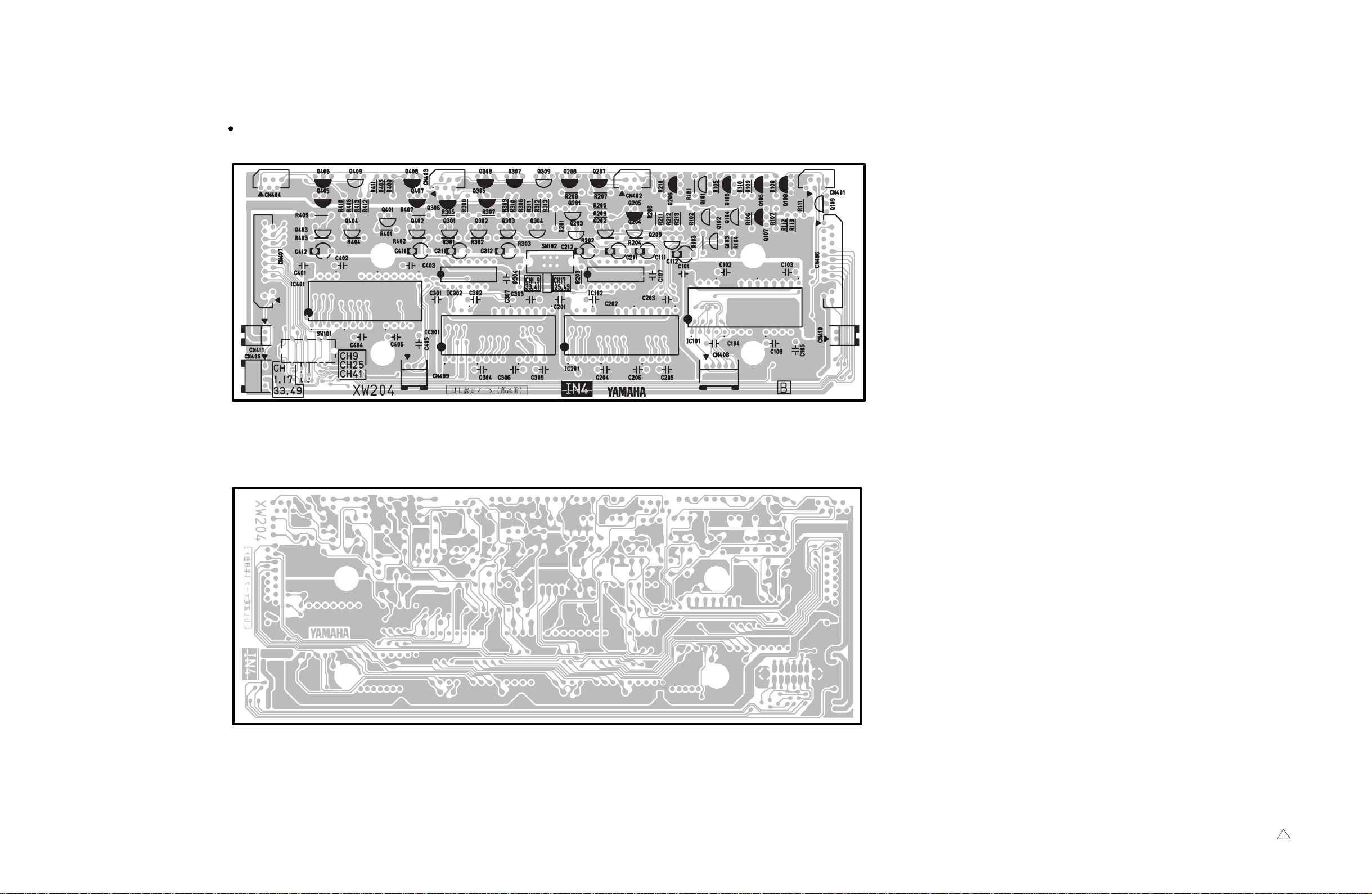
IN4 Circuit Board
to IN3-CN305 to IN3-CN305 to IN3-CN304 to IN3-CN303
to IN4-CN406
ISRT-CN401
NC
to IN4-CN410
ISRT-CN239
NC
to IN3-CN315
to IN3-CN317
to IN3-CN316
to IN4-CN407
ISRT-CN502
NC
to IN4-CN411
ISRT-CN315
NC
Component side
46
Pattern side
3NA-V431360 1
Page 31

INJK Circuit Board
M2500
to IN1-CN102 to IN1-CN101
Component side
INPAN Circuit Board
to IN3-CN307 to IN3-CN308 to IN3-CN309
to IN3-CN310
Component side
INJK: 3NA-V431270 1
INPAN: 3NA-V431340 2
47
Page 32

M2500
ISRT 1/6 Circuit Board
to METER
ISRT 4/6 Circuit Board
to IN4-CN407
to ST4
-CN405
to MAS2
-CN211
to ISRT 4/6
-CN403
to IN4
-CN406
Component side
ISRT 5/6 Circuit Board
to MAS1
-CN104
to ISRT 2/6
-CN234
to ISRT 2/6
-CN236
to MAS1
-CN103
to MAS3-CN305
to MAS3
-CN306
to ISRT 2/6
-CN235
to MAS2
-CN202
to MAS2
-CN203
to MAS2
-CN208
to MAS3
-CN307
Component side
to MAS2
-CN213
to CTRL
-CN224
to CTRL
-CN225
to CTRL
-CN226
to CTRL
-CN230
to CTRL 2/6
-CN220
to ISRT 5/6
-CN501
Pattern side
ISRT 6/6 Circuit Board
Component side
Pattern side
48
Pattern side
Component side
Pattern side
ISRT: 3NA-V431470 1
Page 33

ISRT 2/6 Circuit Board
CN208:
to IN3(L)-CN312
CN207:
to IN3(*L)-GND
CN206:
to IN3(L)-CN312
CN210:
to IN2(L)-GND
CN203:
to IN2(L)-CN208
CN202:
to IN2(L)-GND
CN201:
to IN2(L)-CN206
to IN4(L)-CN411
to IN3(L)-CN314
to IN1(L)-CN106
CN216: to ST3-CN7
CN215: to ST1-CN104
CN238: to ST2-CN210
CN227:
to STJK2/2-CN102
DCIN
CN229: DCIN(1P)
CN234:
to ISRT 1/6-CN101
CN235:
to ISRT 1/6-CN103
M2500
CN251: to ST2-CN206
CN252: to ST2-CN207
CN253: to ST2-CN208
CN254: to ST2-CN209
CN255: to ST2-CN208
CN256: to ST3-CN308
CN257: to ST3-CN310
CN258: to ST3-CN308
to MAS2-CN218
to MAS3-CN314
ISRT 3/6 Circuit Board
ISRT: 3NA-V431470 1
to ISRT3/6-CN309
to ISRT2/6-CN209 to ISRT2/6-CN214
to MAS3
-CN319
to MAS2
-CN221
Component side
Component side
to ISRT 1/6
-CN104
to MAS1
-CN105
to MAS1-CN109
CN214:
to ISRT3/6-CN312
to METER
CN220:
to ISRT4/6-CN407
CN228:
to ISRT6/6-CN601
CN225: to MAS2-CN212
CN237: to MAS2-CN222
CN313: to IN3(R)-CN313
CN315: to IN4(R)-CN410
CN301: to IN2(R)-CN205
CN302: to IN2(R)-GND
CN303: to IN2(R)-CN207
CN304: to IN2(R)-GND
to IN1(R)
-CN105
CN305: to IN2(R)-CN207
CN310: to IN2(R)-GND
CN306: to IN3(R)-CN311
CN307: to IN3(R)-GND
CN308: to IN3(R)-CN311
Pattern side
Pattern side
49
Page 34

M2500
MAS1 1/2 Circuit Board
to MASOUT-CN321
to MASOUT-CN321 to ISRT-CN111 to ISRT-CN102 to ISRT-CN217
to ISRT
-CN219
MAS1 2/2 Circuit Board
Component side
50
to MAS2-CN201
Component side
to MAS3-CN311 to MAS2-CN215
3NA-V431410 1
Page 35

MAS1 1/2 Circuit Board
MAS1 2/2 Circuit Board
Pattern side
M2500
Pattern side
51
Page 36

M2500
MAS2 1/2, 2/2 Circuit Board
to MAS1-CN108to CTQL-CN123to ISRT-CN106to ISRT-CN105to MAS1-CN106
CN216:
to MAS3-CN312
CN217:
to MAS3-CN313
CN204:
to MASOUT-CN321
CN206:
to MASOUT-CN321
CN205:
to MASOUT-CN321
CN207:
to MASOUT-CN321
CN208:
to ISRT-CN109
to CTRL-CN214
to ISRT-CN408
CN224:
to MAS2 1/2-CN225
CN224:
to MAS2 1/2-CN225
CN225:
to MAS2-CN224
52
to MAS3-CN315 CN222: to ISRT-CN237 to MAS3
-CN320
to MAS3
-CN316
CN221:
to ISRT-CN223
CN214:
to MAS3-CN318
to ISRT-CN225
to ISRT1/6-CN151
CN226:
to MAS3-CN329
Component side
3NA-V431420 1
Page 37

M2500
Pattern side
53
Page 38

M2500
to MAS2
-CN217
MAS3 1/2 Circuit Board
to MASPAN-CN103to MASPAN-CN102 to MASPAN-CN104 to MAS2-CN219
to MAS2-CN226to MASPAN-CN101to ISRT-CN107
MAS3 2/2 Circuit Board
Component side
to MASOUT
-CN321
to MAS2-CN216
CN305:
CN324:
to MAS4-CN401
CN308:
to MASOUT-CN321
CN325:
to MAS4-CN402
CN311:
to MAS1-CN107
CN326:
to MAS4-CN403
CN306:
to ISRT-CN108
CN309:
to MASOUT-CN321
CN327:
to MAS4-CN404
CN314:
to ISRT-CN221
CN307:
to ISRT-CN110
CN328:
to MAS4-CN405
to MASPAN-CN105
to MAS2-CN214
to ISRT-CN224
Component side
to MAS2-CN219
CN310:
to MASOUT-CN321
3NA-V431440 1
54
Page 39

Pattern side
M2500
Pattern side
55
Page 40

M2500
to MAS3-CN304 to MAS3-CN317
MAS4 Circuit Board
to MAS3-CN328 to MAS3-CN327 to MAS3-CN326 to MAS3-CN325 to MAS3-CN324
to ST4
-CN406
MASPAN 1/2 Circuit Board
to MAS3-CN303 to MAS3-CN302 to MAS3-CN301
MASPAN 2/2 Circuit Board
Component side
56
Component side
Component side
MAS4: 3NA-V431450 2
MASPAN: 3NA-V431430 2
Page 41

to STJK
-CN101
ST1 Circuit Board
M2500
to ST2-CN202
to ST2-CN201
Component side
to ISRT-CN215
3NA-V431370 1
Pattern side
57
Page 42

M2500
ST2 Circuit Board
to ST1-CN202
to ST1-CN102
to ISRT
-CN252
to ISRT
-CN251
to ISRT
-CN253, 255
to ISRT
-CN238
CN209: to ISRT
-CN254
to ST3
-CN302
to ST3
-CN303
to ST3
-CN301
Component side
58
Pattern side
3NA-V431380 1
Page 43

to ST2
-CN204
ST3 Circuit Board
CN301: to ST2-CN203
CN302: to ST2-CN205
to ST4-CN402
M2500
to ST4-CN404
to ST4
-CN403
to ISRT
-CN256, 258
to ISRT
-CN257
to ISRT
-CN216
Component side
to ST4
-CN401
3NA-V431390 2
Pattern side
59
Page 44

to ISRT-CN227
to ST1-CN101
M2500
to ST3
-CN305
to MAS4
-CN406
to ST3
-CN309
ST4 Circuit Board
to ST3
-CN304
to ISRT
-CN402
STJK 1/2 Circuit Board
STJK 2/2 Circuit Board
Component side
Component side
Component side
to ST3-CN306
60
Pattern side
ST4: 3NA-V431400 1
STJK: 3NA-V431300 1
Page 45

M2500
DISASSEMBLY PROCEDURE
A Assembly
1 Meter Panel
1-1 Remov e the screws marked [210], [220] and [230].
The Meter Panel can then be removed. (Fig. 1)
The type and quantity of the screws marked [210]
and [220] are:
[210]: 24CH:10, 32CH:11, 40CH:13, 48CH:14, 56CH:15
[220]: 24CH:7, 32CH:8, 40CH:9, 48CH:10, 56CH:11
2 MONO Assembly
2-1 Remove the meter panel (See Procedure 1.)
2-2 Remove the screws marked [160] and [180]. (Fig. 1)
Lift the fader side of the control panel and then
remove the MONO Assembly by pulling it forward.
[160]: 40CH:21, 56CH:31
[180]: 24CH:26, 32CH:31, 40CH:26, 48CH:52, 56CH:26
Rear view
Top view
(Bottom)
[210] [110]
[220]
(Top)
(REAR)
Side view
[230]
18
(FRONT)
[120] [160][180]
[120]: Bind Head Tapping Screw-B 3.0X8 FMZN2BL (EP600190)
[160]: Bind Head Tapping Screw-B 3.0X8 FMZN2BL (EP600190)
[180]: Bind Head Tapping Screw-B 3.0X8 FMZN2BL (EP600190)
[210]: Bind Head Tapping Screw-B 4.0X8 FMZN2BL (EG340190)
[220]: Bind Head Screw 4.0X8 FMZN2BL (EG340360)
[230]: Bind Head Screw 4.0X25 MFZN2BL
Fig.1
Page 46

3 MASTER Assembly
3-1 Remove the meter panel. (See Procedure 1.)
3-2 Remove the twenty [20] screws marked [120]. Lift
the fader side of the control panel, remove the
connectors and then remove the MASTER Assembly
by pulling it forward. (Fig. 1)
B Circuit Board
1 MONO Assembly
1-1 Remove the meter panel. (See Procedure A1.)
1-2 Remove the MONO assembly. (See Procedure A2.)
1-3 Remove the follo wing circuit boards by remo ving the
screws indicated for each of them. (Fig. 2)
M2500
Circuit Board & Unit
IN1
IN2
IN3
IN4
Ref No.
40
70
130
150
PARTS NAME
Hexagon Socket Tapping Screw-P 3X25 MFZNBL
Hexagon Socket Tapping Screw-P 3X25 MFZNBL
Bind Head Tapping Screw-B 3.0X8 MFZN2BL
PCB Support CS-0305 KSS
[40]
[70] [70]
[40]
PARTS No.
V3289800
V3289800
EP600190
EP600230
IN1
IN2
Q'ty
11
9
8
4
[180]
[120]
[180]
[120]
[130][130]
Fig.2
INPAN
IN3
IN4
19
Page 47

M2500
2 MASTER Assembly
2-1 Remove the meter panel. (See Procedure A1.)
2-2 Remove the MASTER assembly . (See Procedure A3.)
2-3 Remove the f ollowing circuit boards according to the
listed order by removing the screws indicated for
each of them. (Fig3)
Circuit Board & Unit
ST1
ST2
ST3
ST4
Circuit Board & Unit
MAS1
MAS2 1/2
MAS2 2/2
MAS3 1/2
MAS3 2/2
MASPAN 1/2
MASPAN 2/2
Circuit Board & Unit
CTRL 1/5~4/5
CTRL 5/5
*1 OVERALL ASSEMBLY
Ref No.
60
90
150
140
170
Ref No.
220
280
270
290
350
340
400
400
Ref No.
470
110*
PARTS NAME
Hexagon Socket Tapping Screw-P 3X25 MFZNBL
Hexagon Socket Tapping Screw-P 3X25 MFZNBL
Hexagon Socket Tapping Screw-P 3X25 MFZNBL
Bind Head Tapping Screw-B 3.0X8 MFZN2BL
PCB Support CBS-6K
PARTS NAME
Hexagon Socket Tapping Screw-P 3X25 MFZNBL
Hexagon Socket Tapping Screw-P 3X25 MFZNBL
Bind Head Tapping Screw-B 3.0X8 MFZN2BL
Bonding Tapping Screw-B 3.0X8 MFZN2BL
Hexagon Socket Tapping Screw-P 3X25 MFZNBL
Bind Head Tapping Screw-B 3.0X8 MFZN2BL
Nut
Bind Head Tapping Screw-B 3.0X8 MFZN2BL
Bind Head Tapping Screw-B 3.0X8 MFZN2BL
PARTS NAME
Bind Head Tapping Screw-B 3.0X8 MFZN2BL
1
Bonding Tapping Screw-B 3.0X8 MFZN2BL
PARTS No.
V3289800
V3289800
V3289800
EP600190
PARTS No.
V3289800
V3289800
EP600190
VN413300
V3289800
EP600190
EP600190
EP600190
PARTS No.
EP600190
VN413300
Q'ty
8
6
2
4
4
Q'ty
12
8
6
2
5
10
2
2
Q'ty
12
2
20
Page 48

[60]
[90]
[220]
[280]
[270]
[290]
CTRL
CTRL
CTRL
[470]
5/5
4/5
3/5
MAS1
MAS2 1/2
M2500
ST1
ST2
[150]
[140]
[140]
[340]
[280]
[400]
[350]
[470]
[470]
CTRL
1/5
[470]
CTRL
2/5
MAS3 2/2
Fig.3
Battery VN103500
VN103600(Battery holder for VN103500)
MAS2 2/2
MASPANMASPAN
MAS3 1/2
MAS4
1/22/2
ST3
ST4
• Notice for back-up battery removal
Push the battery as shows in figure,
then the battery will pop up.
• Druk de batterij naar beneden zoals
aangeven in de tekening, de batterij
springt dan naar voren.
Note that the battery is installed on the CTRL circuit board
but it is not a component part.
21
Page 49

M2500
3 MASOUT 1, 2, 3
3-1 Remove the meter panel. (See Procedure A1.)
3-2 Remove the MASTER assembly . (See Procedure A3.)
3-3 Remove the twelve (12) screws marked [30] from
the rear panel. The MASOUT 1 circuit board can
then be removed. (Fig. 4)
3-4 Remove the forty-eight (48) screws marked [50] from
the rear panel. The MASOUT 2 circuit board can
then be removed. (Fig. 4)
3-5 Remove the twelve (12) screws marked [70] from
the rear panel. The MASOUT 3 circuit board can
then be removed. (Fig. 4)
4 ISRT 1/6 ~ 6/6
4-1 Remove the meter panel. (See Procedure A1.)
4-2 Remove the MASTER assembly . (See Procedure A3.)
4-3 Remove the MONO assembly. (See Procedure A2.)
Remove the follo wing circuit boards according to the
listed order by removing the screws indicated for
each of them.
Circuit Board & Unit
ISRT 1/6
ISRT 2/6
ISRT 3/6
ISRT 4/6
ISRT 5/6
ISRT 6/6
Ref No.
380
420
440
390
440
390
390
390
390
PARTS NAME
PCB Support CBS-6K GIN LIAN
Bind Head Screw 4.0X8 MFZN2BL
Bind Head Screw 4.0X8 MFZN2BL
Bind Head Tapping Screw-B 3.0X8 MFZN2BL
Bind Head Screw 4.0X8 MFZN2BL
Bind Head Screw 4.0X8 MFZN2BL
Bind Head Screw 4.0X8 MFZN2BL
Bind Head Screw 4.0X8 MFZN2BL
Bind Head Screw 4.0X8 MFZN2BL
PARTS No.
VZ336600
EG340360
EG340360
EP600190
EG340360
EG340360
EG340360
EG340360
EG340360
Q'ty
4
4
4
8
4
4
4
4
1
22
Page 50

M2500
[110][50] [30] [70]
[390]
4/6
[390]
5/6
[390]
2/6
[420] [440]
6/6
[440]
3/6
[390]
[380]
Earth Bar(LARGE
)
[390]
Bus Earth Bar
1/6
CTRL 5/5MASOUT3MASOUT1MASOUT2
INST INST
INST
ISRT
INST
ISRT
[30]: Bonding Tapping Screw-B 3.0X8 MFZN2BL (VN413300)
[50]: Bonding Tapping Screw-B 3.0X8 MFZN2BL (VN413300)
[70]: Bonding Tapping Screw-B 3.0X8 MFZN2BL (VN413300)
Fig.4
Fig.5
23
Page 51

M2500
5 INJK
5-1 Remove the meter panel. (See Procedure A1.)
5-2 Remove the MONO assembly. (See Procedure A2.)
5-3 Remov e the screws marked [460] and the hexagonalnuts
marked [A] from the rear panel. The INJK can then be
removed. (Fig. 6)
6 STJK
6-1 Remove the meter panel. (See Procedure A1.)
6-2 Remove the MASTER assembly . (See Procedure A3.)
6-3 Remove the two (2) screws marked [480] and the
six (6) hexagonal nuts marked [B]
from the rear panel. The STJK can then be remo ved.
(Fig. 6)
7 Meter 1 and Meter 2
7-1 Remove the meter panel. (See Procedure A1.)
7-2 Remove the f our (4) screws marked [80]. The Meters
can then be removed. (Fig. 7)
7-3 Remove the Meter 1 1/3 to 3/3 circuit boards by
removing the seven (7) scre ws marked [70]. (Fig. 7)
7-4 Remove the Meter 2 1/2 circuit board by removing
the seven (7) screws marked [70]. (Fig. 7)
7-5 Remove the Meter 2 2/2 circuit board by removing
the five (5) screws marked [70]. (Fig. 7)
24
INJK STJK INJK
[460] [480] [460]
INJKSTJKINJK
[460]: Bonding Tapping Screw-B 3.0X8 MFZN2BL (VN413300)
[480]: Bonding Tapping Screw-B 3.0X8 MFZN2BL (VN413300)
Fig.6
Page 52

M2500
[70] [70]
[70]
[70]
METER1METER1
METER1
METER2 2/2
METER2 2/2
2/33/3
1/3
3/3METER2 1/2
[70]
2/3
1/3
2/3METER2 1/2
1/3METER2 1/2
[80] [80] [80] [80]
[70]: Bind Head Tapping Screw-B 3.0X8 MFZN2BL (EP600190)
Fig.7
25
Page 53

M2500
0
R
/
L
A
E
E
LSI PIN DESCRIPTION
HD6435208A00P (XK278A00) CPU <H8/520>
PIN
NO.
10 /WR O Write strobe 42 AVCC Analog power supply
11 VCC Power supply 43 P50 O
12 MD0 I 44 P51 O
13 MD1 I Mode select 45 P52 O
14 MD2 I 46 P53 O Port 5
15 /RES I Reset 47 P54 O
16 NMI I Non-maskable interrupt request 48 P55 O
17 VSS Ground 49 P56 O
18 D0 I/O 50 P57 O
19 D1 I/O 51 VSS Ground
20 D2 I/O 52 AVSS Analog ground
21 D3 I/O Data bus 53 AN0 I
22 D4 I/O 54 AN1 I Analog data input
23 D5 I/O 55 AN2 I
24 D6 I/O 56 AN3 I
25 D7 I/O 57 AVCC Analog power supply
26 A0 O 58 TXD2 O Transmit data
27 A1 O 59 RXD2 I Receive data
28 A2 O 60 A19 O Address bus
29 A3 O Address bus 61 TXD1 O Transmit data
30 A4 O 62 RXD1 I Receive data
31 A5 O 63 SCLK I Clock for serial operation
32 A6 O 64 VSS Ground
NAME I/O FUNCTION
1 EXT I Clock 33 A7 O
2 EXTAL I 34 A8 O
3 /WAIT I Bus cycle wait 35 A9 O
4 /IRQ0 O Interrupt request 36 A10 O
5 A18 O 37 A11 O Address bus
6 A17 O Address bus 38 A12 O
7 A16 O 39 A13 O
8 /AS O Address strobe 40 A14 O
9 /RD O Read strobe 41 A15 O
PIN
NO.
NAME I/O FUNCTION
AK4320-VM-E1 (XR361A00) DAC
PIN
NO.
NAME I/O FUNCTION
1 CKS I Clock select 13 DEM1 I De-emphasis mode
2 DVDD Digital VDD 14 DIF
3 DVSS Digital GND 15 DIF1 I
4XTOO Xtal out 16 VCNT I Mute Control
5 XTI I Xtal in 17 AOUT
6
7 BICK I Serial bit clock 19 VCOM O Common
8 SDAT
9 LRCK I L/R clock 21 AVSS Analog VSS
10 SMUT
11 HOLD I Soft mute hold 23 DZF O Zero input
12 DEM0 I De-emphasis mode 24 ZMUT
PD I Power down 18 AOUT
I Serial data input 20 AVDD Analog VDD
I Soft mute 22 VREF I V reference
PIN
NO.
NAME I/O FUNCTION
I
O Analog output R
O Analog output L
I Zero mute
Input format
26
Page 54

LZ95300 (XP451A00) Gate Array
PIN
NO.
NAME I/O FUNCTION
PIN
NO.
NAME I/O FUNCTION
1 INC O INPUT CUE ON/OFF 15 /CSW I CUE switch input
2 CPR O VCA CUE PRE PAN ON/OFF 16 VCA8 I
3 CPST O VCA CUE POST PAN ON/OFF 17 VCA7 I
4 COFF O All CUE OFF 18 VCA6 I
5 CPU I H: CPU mode, L: Local mode 19 VCA5 I VCA GROUP switch input
6 C0 I 20 VCA4 I
7 C1 I CPU address bus 2 1 VCA3 I
8 C2 I 22 VCA2 I
9 C3 I 23 VCA1 I
10 /RES I Reset 24 /SLSF I SOLO SAFE switch input
11 DATA I/O Data input/output 25 /CHK I CHECK LED ON/OFF
12 IRQ O
When /ONSW and /CSW change; H.
When CPU reads data; L.
26 /ONSW I ON switch input
13 /CS I Chip select 27 /ONRY O ON relay & LED ON/OFF
14 GND Digital ground 28 VDD Digital power supply
Function of DATA
DATA
C3 C2 C1 C0 R/W
MODE FUNCTION 0 1
0000WON RELAY SET Sets /ONRY OFF ON
0001 RON SW READ Reads /ONSW OFF ON
0010WCUE RELAY SET Sets INC ON OFF ON
0011 RCUE SW READ Reads /CSW OFF ON
0100WCHECK LED SET Sets /CHK OFF ON
0101WVCA PRE/POST SET Sets CVCA CUE PRE/POST PAN POST PRE
0110WSOLO SET
Sets SOLO
When SOLO is set, CUE or
SOLO SAFE is not ON, /ONRY is
set to OFF.
OFF SOLO
0111WVCA1 CUE SET Sets VCA1 CUE OFF ON
1000WVCA1 CUE SET Sets VCA1 CUE OFF ON
1001WVCA2 CUE SET Sets VCA2 CUE OFF ON
:::: : : : : :
:: : ::
1111WVCA8 CUE SET Sets VCA8 CUE OFF ON
M2500
::::
27
Page 55

M2500
C
4
)
3
)
2
)
2
)
k
0
t
A
)
)
YSP99 LZ95XD59 (XM047A00) Gate Array
PIN
NO.
NAME I/O FUNCTION
1NC 41A9 I
2 MCLK O Master clock 42 A8 I
3 DESYN O Sync for DEQI
4 CD04 I 44 CD1 I
5 CD03 I 45 CDROM I CARD/ROM select
6 CD02 I 46 ROM4 I
7 CD01 I 47 ROM3 I
8 CDI
9 CDI
10 CDI
11 CDI1 O Control data output (DEQ IC19
12 +Vdd 52 GND
13 GND 53 +Vdd
14 L4 O 54 SEL2 I
15 L3 O 55 SEL1 I
16 L2 O 56 XX2 I
17 L1 O 57 XX1 I
18 LCD O LCD enable 58 MDCK O MIDI cloc
19 KEYN O KEY enable 59 TRG
20 LED O LED enable 60 E I
21 CDA14 O 61 RWN I Read write pulse
22 CDA13 O 62 ICN I Initial clear
23 CARDN O CARD enable 63 ACI
24 GND 64 GND
25 RAWN O RAM write enable 65 TXD I DSP control data input
26 RAON O RAM read enable 66 RXD O DSP control data output
27 RMA16 O 67 XCLK O Transfer clock
28 RMA15 O 68 WCLK O Word clock
29 RMA14 O 69 SCLK O Serial data transfer clock 64fs
30 RMA13 O 70 FSYNC O N C
31 +Vdd 71 ADLR O NC
32 GND 72 GND
33 ROMN O ROM read enable 73 +Vdd
34 A15 I 74 SCLKN O Serial data sift clock
35 A14 I 75 DCLK O 256fs clock
36 A13 I 76 XI I Clock input/(Xtal
37 A12 I 77 XO O output/(Xtal
38 A11 I 78 GND
39 A10 I 79 TRIG I Trigger input
40 NC 80 SYNCN O Sync clock
O Control data output (DSP2
O Control data output (MOD
O Control data output (DEQ IC17
Control data input
LED scan pulse
CARD address
ROM address back select
CPU address bus
PIN
NO.
NAME I/O FUNCTION
43 CD2 I
48 ROM2 I
49 ROM1 I
50 YY
51 YY1 I
CARD page select
ROM page control
I
Dividing select
Control data select
O Trigger ou
O ACIA enable
28
Page 56

M2500
YSS228E-F (XQ962D00) DSP3 (Digital Signal Processor)
PIN
NO.
10
11
12
13
14
15
16
17
18
19
20
21
22
23
24
25
26
27
28
29
30
31
32
33
34
35
36
37
38
39
40
41
42
43
44
45
46
47
48
49
50
51
52
53
54
55
56
57
58
59
60
61
62
63
64
65
66
67
68
69
70
71
72
73
74
75
76
77
78
79
80
NAME
VSS
1
2
3
VDD
4
/SYNCI
5
/SYNCO
6
CKI
7
CKO
8
CKSL
9
VSS
MCKS
/SSYNC
/TEST
BTYP
/IRQ
TRIG
VDD
VSS
/CS
/DS
R/W
CA7
CA6
CA5
CA4
CA3
CA2
CA1
CA0/CD15
CD14
CD13
CD12
CD11
CD10
CD09
CD08
CD07
CD06
VSS
VDD
CD05
CD04
CD03
CD02
CD01
CD00
/DTACK
SI0
SI1
SI2
SI3
SI4
SI5
SI6
SI7
VSS
VDD
SO0
SO1
SO2
SO3
SO4
SO5
SO6
SO7
DB00
DB01
DB02
DB03
DB04
DB05
DB06
DB07
DB08
DB09
DB10
DB11
DB12
VDD
XI
XO
/IC
I/O
O
O
O
I/O
I/O
I/O
I/O
I/O
I/O
I/O
I/O
I/O
I/O
I/O
I/O
I/O
I/O
I/O
I/O
I/O
O
O
O
O
O
O
O
O
O
I/O
I/O
I/O
I/O
I/O
I/O
I/O
I/O
I/O
I/O
I/O
I/O
I/O
FUNCTION
Ground
I
I
I
I
I
I
I
I
I
I
I
I
I
I
I
I
I
I
I
I
I
I
I
I
I
I
I
System master clock input (60 M or30 MHz)
System master clock input (60 M or30 MHz)
Power supply
System synch. input
System synch. output
System clock input (30 MHz)
System clock output (30 MHz)
System master clock select (0:60 M,1:30 MHz)
Ground
Master clock for serial I/O(128 xFs)
Synch. signal for serial I/O
Initial clear
Test mode setting
CPU data bus 8/16 bit select(0:8,1:16)
Interrupt request
Trigger signal
Power supply
Ground
Chip select
Data strobe
Read/Write select
CPU address bus
CPU address/data bus
CPU data bus
Ground
Power supply
CPU data bus
DTACK signal output
Serial data input
Ground
Power supply
Serial data output
Parallel data bus
Power supply
PIN
NO.
81
82
83
84
85
86
87
88
89
90
91
92
93
94
95
96
97
98
99
100
101
102
103
104
105
106
107
108
109
110
111
112
113
114
115
116
117
118
119
120
121
122
123
124
125
126
127
128
129
130
131
132
133
134
135
136
137
138
139
140
141
142
143
144
145
146
147
148
149
150
151
152
153
154
155
156
157
158
159
160
NAME
VSS
DB13
DB14
DB15
DB16
DB17
DB18
DB19
DB20
DB21
DB22
DB23
DB24
DB25
DB26
DB27
DB28
DB29
DB30
DB31
TIMO/DBOE
VSS
VDD
DA00
DA01
DA02
DA03
DA04
DA05
DA06
DA07
DA08
DA09
DA10
DA11
DA12
DA13
DA14
DA15
VSS
VDD
DA16
DA17
DA18
DA19
DA20
DA21
DA22
DA23
DA24
DA25
DA26
DA27
DA28
DA29
DA30
DA31
VDD
VSS
A00
A01
A02
A03
A04
A05
A06
A07
A08
A09
A10
A11
A12
A13
A14
A15/RAS
A16/CAS
A17/CE
/WE
/OE
VDD
I/O
I/O
I/O
I/O
I/O
I/O
I/O
I/O
I/O
I/O
I/O
I/O
I/O
I/O
I/O
I/O
I/O
I/O
I/O
I/O
I/O
I/O
I/O
I/O
I/O
I/O
I/O
I/O
I/O
I/O
I/O
I/O
I/O
I/O
I/O
I/O
I/O
I/O
I/O
I/O
I/O
I/O
I/O
I/O
I/O
I/O
I/O
I/O
I/O
I/O
I/O
I/O
I/O
I/O
DM : IC2, 3
FUNCTION
Ground
Parallel data bus
Timing signal/Parallel data bus control
Ground
Power supply
External memory data bus
Ground
Power supply
External memory data bus
Power supply
O
O
O
O
O
O
O
O
O
O
O
O
O
O
O
O
O
O
O
O
Ground
External memory address bus
External memory address bus/Row address strobe
External memory address bus/Column address strobe
External memory address bus/Chip enable
External memory write enable
External memory output enable
Power supply
29
Page 57

M2500
IC BLOCK DIAGRAM
BA6144 (XA552A00)
ST4: IC121,IC221,IC321,IC421
IN3: IC103,IC203,IC303,IC403,
IC503,IC603,IC703,IC803
METER DRIVER
+ + + + +
1 2 3 4 5 6 7 8 9
+
CONSTANT
CURRENT
NJM2068-D(XM356A00
)
ST1: IC101~106,IC201~204,
IC301~305,IC401~404
MAS3: IC952,IC953
MAS2: IC101,IC151,IC301,IC351,IC501,
IC551,IC751,IC901~903
MAS1: IC101~103,IC301~303,IC501~503,
IC701~703
ISRT:
IC101~104,IC111~115,IC121~124,
IC201~217
IN1: IC103~107,IC303~307,IC503~507,
IC703~707
NJM2082M(T1)(XN797A00)
CTRL: IC108
NJM4558L-D(XQ212A00)
METER1: IC102
METER2: IC102
NJM4556AL(XP844A00)
MAS: IC951
NJM4580L(XF195A00)
ST2: IC101~103,IC301~303
ST3: IC101,IC201,IC301,IC401
MASOUT3:
MSOUT1,2:
MAS3: IC101,IC301,IC501,IC701,
IC901,IC902
MAS1: IC901
IN3: IC101,IC102,IC301,IC501,IC502,
IC701,IC702
IN1: IC101,IC102,IC301,IC501,IC502,
IC701,IC702
M5238AP(XM085A00)
DC: IC101,IC201,IC202
OP AMP OP AMP
+
1A2 3 4 5 6 7 8
IN V
+
IN
OUT
AAA
+
+
IN
BBB
B
OUT
1Output A
2
Inverting
Input A
Input A
DC Voltage
Supply
3
4
+
VIN
Non-Inverting
IC101,IC201,IC301
IC301,IC201,IC301,IC401
+DC Voltage
+V
8
Supply
7
6
5
Output B
Inverting
Input B
Non-Inverting
Input B
+
+
V
SN74HC00NSR (XE165A00)
CTRL: IC113
SN74HC04NSR (XD830A00)
CTRL: IC109
NAND INVERTER DECODER
1
1A
2
1Y
3
2A
4
2Y
5
3A
6
3Y
7
Vss
14
VDD
13
6A
12
6Y
11
5A
10
5Y
9
4A
8
4Y
30
1
1A
2
1B
3
1Y
4
2A
5
2B
6
2Y
7
SS
V
14
V
DD
13
4B
12
4A
11
4Y
10
3B
9
3A
8
3Y
SN74HC138NSR (XD835A00)
CTRL: IC124
Select
Enable
Output
1
A
2
B
3
C
4
G2A G2A
5
G2B G2B
6
G1 G1
7
Y7 Y7
8
GND
B
C
16
A
Y6
Vcc
15
Y0Y0
14
Y1Y1
13
Y2Y2
12
Y3
Y3
Output
11
Y4Y4
10
Y5Y5
9
Y6
Page 58

M2500
SN74HC14NSR (XC725A00)
CTRL: IC110,IC302
SN74HC174NSR (XD836A00)
CTRL: IC123
SN74HC245NSR (XD838A00)
CTRL: IC121,IC125,IC131
INVERTER D-FF BUFFER
GND
11A
2
1Y
3
2A
4
2Y
5
3A
6
3Y
7
DD
V
14
6A
13
6Y
12
5A
11
5Y
10
4A
9
4Y
8
SN74HC273NSR (XH223A00)
CTRL: IC132
1
CLEAR
2
DD
1Q
GG
QQ
CK CK
3
1D
4
2D
DCK
G
5
Q
2Q
6
DCK
3D
G
Q
7
3Q
8
GND
SN74HC32NSR (XD833A00)
CTRL: IC112
16
Vcc
15
6Q
14
6D
13
5D
DCK
G
Q
12
5Q
11
DCK
4D
G
Q
10
4Q
9
CK
A1
A2
A3
A4
A5
A6
A7
A8
GND
SN74HC374ANSR (XQ042A00)
CTRL: IC122
D-FF OR D-FF
GND
1CLEAR
2
1Q
3
1D
4
2D
5
2Q
6
3Q
7
3D
8
4D
9
4Q
10
QQ
CL CL
CK CK
DD
D
CL
QQ
QQ
CL CL
CK
D
DDCK
CL
Q
CC
V
20
8Q
19
8D
18
7D
17
CK
DCK
CL
7Q
16
6Q
15
CK
D
6D
14
5D
13
CK
CL
Q
5Q
12
CLOCK
11
11A
2
1B
3
1Y
4
2A
5
2B
6
2Y
7
GND
CC
V
14
4B
13
4A
12
4Y
11
3B
10
3A
9
3Y
8
OUTPUT
CONTROL
GND
1Q
1D
2D
2Q
3Q
3D
4D
4Q
1D1R
2
3
4
5
6
7
8
9
10
1 20
2 19
Q
Q
OE
OE
DCK
DCK
Q
Q
DCK
DCK
Q
DCK
DCK
OE
OE
Q
Q
OE
OE
DCK
DCK
OE
OE
Q
3 18
4 17
5 16
6 15
7 14
8 13
9 12
10 11
20
19
18
17
16
15
14
13
12
11
CC
V
G
B1
B2
B3
B4
B5
B6
B7
B8
Vcc
8Q
8D
7D
7Q
6Q
6D
5D
5Q
CLOCK
TC4052BP (XA053A00)
METER1: IC101
METER2: IC101
SN74HC02AP (IR000200)
ST4: IC102 MAS4: IC102,502,902
IN4: IC102,IC302
MULTIPLEXER NOR
Y-COM
1
0Y
2
2Y
2Y
Y-COM
3
3Y
4
3Y
5
1Y
1Y
6
INH
INH
7
V
EE
8
VSS
0Y
X-COM
B
16
DD
V
2X
15
2X
14
1X
1X
13
X-COM
0X
12
0X
11
3X
3X
A
10
A
9
B
SN74HC139AP (IR013900)
MAS2: IC910
DECODER
1
1G
1
1Y
2
1A
3
1B
4
2Y
5
2A
6
2B
7
Vss
14
Vcc
13
4Y
12
4A
11
4B
10
3Y
9
3A
8
3B
GND
G
2
A
1A
3
1B
B
4
1Y0
Y0
5
1Y1
Y1
6
1Y2
Y2
7
1Y3
Y3
8
16
Vcc
G
15
2G
A
14
2A
B
13
2B
Y0
12
2Y0
Y1
11
2Y1
Y2
10
2Y2
Y3
9
2Y3
31
Page 59

Page 60

ABCDEFGHI JKLMNOPQ
)
1
IN1
INJK
2
<P.3>M2500 OVERALL CIRCUIT DIAGRAM(IN1,IN2,INJK
OP AMP
OP AMP OP AMP
OP AMP
OP AMP OP AMP
NEXT P.C.B.
(O2)
[P.11 - L3]
NEXT P.C.B.(K2
[P.11 - H9]
M2500
1
)
2
3
3
4
4
5
5
IN2
6
OP AMP
OP AMP OP AMP
OP AMP
OP AMP OP AMP
NEXT P.C.B.(P7
[P.11 - K1]
)
NEXT P.C.B.
(K7)
7
[P.11 - K3]
6
7
8
9
10
NEXT P.C.B.(P9
ISRT-CN303
[P.11 - K1]
ISRT-CN305
[P.11 - L1]
8
9
)
NEXT P.C.B.
(L9)
ISRT-CN203
[P.11 - K3]
ISRT-CN205
[P.11 - L3]
10
11
12
11
[P.4 - I5][P.4 - B4,5]
M2500M2500
12
ABCDEFGHI JKLMNOPQ
Page 61

1 2 3 4 5 6 7 8 9 10 11 12
A
B
M2500 WIRING
<P.12>
METER1
METER1METER1
3/32/3
1/3
MSOUT2
MASOUT
MAS1
1/2
ISRT
1/6
ISRT
M2500
A
B
6/6
C
D
E
METER1
METER1 METER1
2/3 3/3
METER1
METER1 METER1
2/3 3/3
METER1
1/3
1/3
1/3
MASOUT
MASOUT
MASOUT
MASOUT
MAS2
2/2
MAS2
1/2
ISRT
C
2/6
D
(J6)
E
G
MASOUT
(P4)
METER1 METER1
2/3 3/3
CTRL
MAS1
F
2/2
MASOUT
MAS3
1/3
F
(P4)
MASPAN
METER2 1/2
1/3
MSOUT3
METER2 1/2 METER2 1/2
2/3 3/3
MSOUT3
MAS3
G
2/2
H
METER2 2/2
1/3
MAS4
METER2 2/2
2/3
(O8)
Those items on the right of this broken line are not used for M2500-24 and M2500-32.
I
1
INJK
INJK
1
H
I
K
2/6 3/6
ISRT ISRT
)(
J
J11
(
IN1
IN1
)
(
J1
J
STJK
(
)
D11
)(
K11
IN2
ST1
IN2
)
K1
(
K
)
K11
)
K1
(
L
M
)(
L11
(
)(
N11
IN3
INPAN
ST2
ST3
IN3
INPAN
)
L1
(
)
N1
(
L
M
N
O
P
)(
O11
)
O11
IN4
(
F11
N
)
O1
(
(H6)
IN4
ST4
)
O1
(
ISRT
4/6
ISRT
5/6
)
)
1
The number of blocks "INJK-IN1-IN2-IN3-INPAN-IN4" varies depending on the ch version.
Blocks on the left of MasterBlocks on the left of Master
O
P
Q
(F7)
M2500 M2500
1 2 3 4 5 6 7 8 9 10 11 12
Q
Page 62

ABCDEFGHI JKLMNOPQ
)
1
IN3
[P.5 - E8]
<P.4>M2500 OVERALL CIRCUIT DIAGRAM(IN3
)
(
B3
)
(
)
H12
NEXT P.C.B.(P12
ISRT-CN306 [P.11 - M1]
ISRT-CN308 [P.11 - N1]
M2500
1
OP AMP OP AMP
2
[P.5 - G8]
[P.5 - E8]
[P.5 - G9]
(M3)
(M5)
(M8)
(
M10
METER
)
DRIVER
(B2)
[P.11 - L3]
[P.11 - H10]
METER
DRIVER
(B2)
OP AMPOP AMP
2
3
3
[P.5 - E8]
)
H2
(
4
4
[P.3 - M11]
OP AMP OP AMP
OP AMP OP AMP
[P.3 - O11]
5
5
METER
DRIVER
[P.5 - B2]
METER
DRIVER
(B3)
[P.5 - B5,6]
(B3)
6
6
[P.5 - B3,4]
7
7
[P.5 - E10]
OP AMP
OP AMP
[P.5 - G10]
OP AMP
OP AMP
METER
DRIVER
METER
DRIVER
8
8
(B3)
(B3)
9
9
OP AMP
OP AMP
OP AMP
OP AMP
10
11
12
METER
DRIVER
(B3)
(O,P2)
[P.5 - B7]
METER
DRIVER
(B3)
NEXT P.C.B.(H1
[P.11 - L3,M3]
10
11
)
M2500M2500
12
ABCDEFGHI JKLMNOPQ
Page 63

ABCDEFGHI JKLMNOPQ
)
1
M2500 OVERALL CIRCUIT DIAGRAM(IN4,INPAN,METER,CTRL 1/5,2/5,3/5,4/5,5/5
INPAN
<P.5>
CTRL
5/5
PhotoCoupler
CTRL
4/5
M2500
1
2
2
[P.4 - B5]
INVERTER
METER
3
3
[P.4 - B6]
[P.11 - I9]
CTRL
2/5
CTRL
3/5
4
4
MULTIPLEXER
DRIVER
OP AMP
DRIVER
5
5
[P.11 - E6]
BUFFER
[P.4 - I5,6]
METER2-1/2 METER2-2/2METER1
install
not install
not install
not install not install
install
install
install
install
6
6
[P.4 - I11]
other
OP AMP
CTRL
1/5
EPROM 512K SRAM 256K
D-FF
7
7
[P.4 - B2]
[P.4 - B3]
8
IN4
OP AMP
INTER FACE
[P.4 - B2]
NEXT P.C.B.(F8)NEXT P.C.B.(E8
[P.11 - M3] [P.11 - H9]
OP AMP
INTER FACE
)
[P.4 - I2]
CPU
GATE ARRAY
INVERTER
NAND
OR
NAND
INVERTER
DSP3
8
9
9
INVERTER
OR
DAC
OR
OP AMP
OP AMP
SYSTEM
RESET
[P.4 - B3]
10
11
NEXT P.C.B.(G11
[P.11 - N6]
INVERTER
BUFFER
D-FF
OP AMP
[P.4 - I7]
[P.4 - B7]
INTER FACE
)
INTER FACE
NEXT P.C.B.(A11
[P.11 - K6]
)
[P.11 - K8]
OP AMP
D-FF
DECODER
[P.11 - M7] [P.11 - M7]
BUFFER
[P.9 - J8]
[P.11 - M6]
[P.9 - N7]
10
11
12
M2500M2500
12
ABCDEFGHI JKLMNOPQ
Page 64

ABCDEFGHI JKLMNOPQ
)
1
<P.6>M2500 OVERALL CIRCUIT DIAGRAM(ST1,ST2
M2500
1
ST1 ST2
2
(K6)
(L4)
(K6)
(M4)
(M6)
(M4)
(M6)
(N4)
[P.7 - E4]
OP AMP
[P.7 - O4]
OP AMP
2
3
3
OP AMP
[P.11 - K5]
[P.11 - K5]
4
4
[P.11 - H11]
OP AMP
(K2)
(K2)(K2)(
5
OP AMP
K2
)
OP AMP
5
(
)
I10
[P.7 - B4]
6
)
K2
(
)
(
K2
OP AMP
[P.7 - B9]
)
K2
(
)
K2
(
OP AMP
6
OP AMP
OP AMP
7
7
OP AMP
8
9
10
OP AMP
OP AMP
OP AMP
(M5)
CN253
[P.11 - K5]
CN255
[P.11 - L5]
8
9
10
[P.11 - L5]
11
12
OP AMP
OP AMP
11
12
OP AMP
[P.11 - H11]
M2500M2500
ABCDEFGHI JKLMNOPQ
Page 65

ABCDEFGHI JKLMNOPQ
)
1
<P.7>M2500 OVERALL CIRCUIT DIAGRAM(ST3,ST4,STJK
to ISRT-CN256 [P.11 - M5]
to ISRT-CN258 [P.11 - M5]
M2500
1
STJK
ST3
[P.11 - I8]
2
OP AMP
(
)
M12
(
)
N11
3
2
3
[P.6 - K6]
[P.6 - B3]
4
4
[P.6 - K2]
OP AMP
5
5
[P.11 - H11]
(I8)
6
6
[P.11 - M5]
METER
ST4
NOR
DRIVER
7
7
(
)
N12
OP AMP
METER
DRIVER
8
8
9
10
[P.6 - M6]
OP AMP
(B6)
[P.11 - L7]
INTERFACE
NOR
9
METER
DRIVER
10
METER
DRIVER
11
12
INTERFACE
[P.8 - J9]
(B3)
(B7)(B2)
M2500M2500
11
12
ABCDEFGHI JKLMNOPQ
Page 66

ABCDEFGHI JKLMNOPQ
)
1
MAS1
2/2
<P.8>M2500 OVERALL CIRCUIT DIAGRAM(MAS1 1/2,MAS1 2/2,MAS4
[P.9 - B2] [P.11 - O9] [P.11 - O9]
M2500
1
2
2
[P.11 - I10]
3
OP AMP
OP AMP
OP AMP
OP AMP
OP AMP
3
MAS1
1/2
4
4
OP AMP
OP AMP
OP AMP
OP AMP
OP AMP
5
5
[P.11 - B5]
[P.9 - B6]
OP AMP
OP AMP
6
6
[P.10 - N6]
[P.11 - I10]
[P.11 - H1]
7
7
MAS4
NOR
8
INTERFACE
INTERFACE
NOR
INTERFACE
NOR
8
9
10
OP AMP
OP AMP
OP AMP
OP AMP
OP AMP
OP AMP
[P.7 - J11]
NOR
[P.10 - B8]
NOR
[P.10 - B9]
[P.10 - B10]
9
10
11
12
[P.10 - B8]
INTERFACE
INTERFACE
[P.10 - B9]
11
M2500M2500
12
ABCDEFGHI JKLMNOPQ
Page 67

ABCDEFGHI JKLMNOPQ
)
1
[P.11 - O9] [P.11 - O9]
<P.9>M2500 OVERALL CIRCUIT DIAGRAM(MAS2
[P.11 - O9]
M2500
1
MAS2
2
[P.8 - E1]
2
3
3
4
4
[P.10 - H11] [P.10 - H11]
OP AMP
OP AMP
OP AMP
OP AMP
OP AMP
OP AMP
OP AMP
OP AMP
OP AMP
OP AMP
5
5
[P.8 - B6]
6
6
[P.11 - G4]
[P.11 - O9]
[P.11 - E2]
7
7
OP AMP OP AMP
[P.5 - P11]
[P.11 - L7]
DECODER
8
9
10
OP AMP
OP AMP
OP AMP
OP AMP
[P.10 - H8]
[P.11 - G11]
[P.10 - M7]
[P.11 - E12]
[P.5 - P10]
[P.11 - E10] [P.10 - H8]
[P.11 - B8]
[P.11 - D6]
8
9
10
11
12
[P.10 - M6]
OP AMP
[P.10 - M6]
[P.11 - E4]
OP AMP
M2500M2500
11
12
ABCDEFGHI JKLMNOPQ
Page 68

ABCDEFGHI JKLMNOPQ
)
1
<P.10>M2500 OVERALL CIRCUIT DIAGRAM(MAS3,MASPAN
M2500
1
MAS3
(A5)
MASPAN
[P.11 - G3]
2
OP AMP
(N7)
(F8)
(B8)
[P.11 - O9]
[P.11 - G3]
(B9)
OP AMP
(N6)
(
F10
[P.11 - O9]
(F8)
2
OP AMP
[P.11 - O9]
)
3
3
(
)
B10
[P.11 - G5]
(B8)
OP AMP
(N7)
(F8)
(B9)
OP AMP
(N6)
(
F10
(D8)
(I8)
)
4
4
OP AMP
(B8)
OP AMP
5
OP AMP
(
B10
)
5
(N6)
(
D10
(
)
)
(
)
H10
[P.9 - H11]
F10
(B8)
(N7)
(D8)
(B9)
6
6
[P.9 - H10]
[P.9 - H9]
(
H2 6
(
D2 6
)
)
[P.8 - D6]
(
D10
)
(B8)
OP AMP
(N7)
(D8)
(B9)
OP AMP
(N6)
(
D10
)
7
7
(O4)(
(B2)
O2
)
[P.9 - K10]
OP AMP
8
8
[P.8 - L8]
[P.8 - L11]
[P.8 - N8]
(B4)
(B5)
(B6,7)
(G2)
(G4)
(D6)(D5)(
)(D2)
D4
[P.9 - H9]
)
M4
(
(J9)
9
9
[P.11 - G9]
[P.11 - O9]
[P.8 - N11]
(G5)
(G6,7)
(O7)
(O6)
(O9)
OP AMP
(M5)
10
11
[P.8 - P8]
[P.11 - B7]
(K3)
(K5)
(H6)(H5)(
)(H2)
H4
10
OP AMP
[P.9 - B4]
11
[P.9 - B4]
12
M2500M2500
12
ABCDEFGHI JKLMNOPQ
Page 69

ABCDEFGHI JKLMNOPQ
1
M2500 OVERALL CIRCUIT DIAGRAM(ISRT 1/6,2/6,3/6,4/5,5/6,6/6,MASOUT
OP AMP
ISRT
1/6
OP AMP
)
G7
(
2
)
[P.9 - K6]
[P.8 - C6]
ISRT
3/6
[P.3 - K7]
RR
[P.3 - K9]
R
RR
[P.3 - K9] [P.4 - H1]
R
R
RR
[P.4 - H1]
M2500
1
2
OP AMP
[P.10 - B2]
3
)
H10
(
R
[P.4 - H3]
R
[P.3 - K2]
R
[P.5 - E8]
3
L
[P.4 - P12]
L
)
(
)(
11
C7
F8
4
[P.9 - D12]
ISRT
2/6
[P.3 - P7]
L
L
[P.3 - P9]
L
L
L
L
[P.4 - P12][P.3 - P9]
L
4
)
B7
(
)
11
[P.9 - D6][P.10 - J4] [P.10 - F2]
[P.8 - B5]
5
)
G8
[P.6 - L3]
[P.6 - L4]
[P.6 - K6]
[P.6 - K6][P.6 - K10] [P.7 - H1]
[P.7 - H1]
[P.7 - F6]
B9
(
)
9
,
E8
(
5
4/6
ISRT
5/6
)(
I11
(
ISRT
6/6
ISRT
(H9)
OP AMP
6
6
[P.9 - N10]
REGULATOR +5V
[P.5 - D5]
L
[P.5 - G11]
[P.7 - I10]
OP AMP
ISRT
(P4)
(P4)
7
[P.10 - B11]
(P4)
2/6
(P4)
(P4)
(P4)
(G8)
(G8)
(G8)
(G8)
(G8)
OP AMP
(G8)
(G8)
)
)
11
11
D9
C9
(
(
8
14
GAP1
AUX7
(P4)
(E7)
(E8)
(E7)
)
B2
(
[P.9 - O8]
[P.5 - O11]
[P.5 - L12]
[P.5 - N12]
)
H9
(
R
[P.5 - B11]
7
(G8)
8
(P4)
(P4)
[P.9 - N8]
(P4)
(G8)
(G8)
(P5)
(G8)
OP AMP
(P5)
(G7)
9
(P4)
(P4)
(P4)
(G7)
(G7)
(P4)
(P4)
(P4)
(G7)
(P5)
(G7)
(G7)
[P.9 - K10]
(G8)
OP AMP
(D7)
(D8)
(D8)
(D9)
(F7)
(F8)
(F8)
)
B5
(
[P.10 - H9]
(C6)
)
M7
(
(
G11
(
E11
[P.5 - I11]
8
to MAS3-CN309 [P.10 - I3]to MAS2-CN207 [P.9 - C7]
to MAS2-CN205 [P.9 - F2]
to MAS2-CN204 [P.9 - C2]
to METER-CN331
)
to MAS2-CN206 [P.9 - K2]
to MAS3-CN321 [P.10 - N9]
to MAS3-CN310 [P.10 - N2]
to MAS3-CN308 [P.10 - E2]
to MAS1 1/2-CN101 [P.8 - G1]
to MAS1 1/2-CN102 [P.8 - L1]
MASOUT
)
9
10
11
12
M2500
(P4)
(P4)
(P4)
(P4)
(P4)
(P4)
(G7)
(G7)
(G7)
(G7)
(G7)
(P4)
(P4)
(P4)
(P4)
(P4)
(G7)
(G7)
(G7)
(G7)
(G7)
(H9)
[P.9 - H10]
)
H9
(
[P.9 - H9]
[P.6 - N11]
[P.4 - I3] [P.3 - O2] [P.5 - F8]
)
J3
(
[P.6 - I4]
[P.7 - A5]
[P.8 - B3] [P.8 - B6] [P.5 - D4] [P.7 - N2]
)
B6
(
KEC-92331
10
11
1
M2500
12
ABCDEFGHI JKLMNOPQ
Page 70

PARTS LIST
MIXING CONSOLE
CONTENTS
OVERALL ASSEMBLY ............................................. 2
CHASSIS ASSEMBLY ................................ 4
MASTERE ASSEMBLY ............................. 8
MONO IN ASSEMBLY
(MONO16, MONO24, MONO32) .......................................... 10
METER PANEL ASSEMBLY ....................... 12
ELECTRICAL PARTS ......................................... 14
Notes : DESTINATION ABBREVIATIONS
A : Australian model
B : British model
C : Canadian model
D : German model
E : European model
F : French model
H : North European model
I : Indonesian model
J : Japanese model
WARNING
Components having special characteristics are marked and must be replaced with parts having
specification equal to those originally installed.
M: South African model
O: Chinese model
Q: South-east Asia model
T : Taiwan model
U : U.S.A. model
V : General export model (110V)
W: General export model (220)
N,X : General export model
Y : Export model
The numbers “QTY” show quantities for each unit.
The parts with “--” in “PART NO.” are not available as spare parts.
This mark “ } ” in the REMARKS column means these parts are interchangeable.
The second letter of the shaded (
The second letter of the shaded (
) part number is O, not zero.
) part number is I, not one.
Page 71

M2500
OVERALL ASSEMBLY
REF NO. PART NO. DESCRIPTION REMARKS QTY
10 Shassis Assembly 24CH (V442480)
10 Shassis Assembly 32CH (V442490)
10 Shassis Assembly 40CH (V442500)
10 Shassis Assembly 48CH (V442510)
10 Shassis Assembly 56CH (V442520)
20 Circuit Board MSOUT1 315
NX819680
30 Bonding Tapping Screw-B 3.0X8 MFZN2BL 60 01
VN413300
40 Circuit Board MSOUT2 13
NX819720
50 Bonding Tapping Screw-B 3.0X8 MFZN2BL 16 01
*
VN413300
60 Circuit Board MASOUT3
AAX09050
70 Bonding Tapping Screw-B 3.0X8 MFZN2BL 16 01
VN413300
100 MASTER Assembly (V442530)
110 Bonding Tapping Screw-B 3.0X8 MFZN2BL 201
VN413300
120 Bind Head Tapping Screw-B 3.0X8 MFZN2BL 17 01
EP600190
150 Mono 16 Assembly 40CH (V442540)
150 MONO 32 Assembly 56CH (V442560)
160 Bind Head Tapping Screw-B 3.0X8 MFZN2BL 40/56CH 21/31 01
EP600190
170 MONO 24 Assembly 24,40,56CH (V442550)
170 MONO 32 Assembly 32CH (V442560)
170 MONO 24 Assembly 48CH (V442550) 2
180 Bind Head Tapping Screw-B 3.0X8 MFZN2BL 26/31/26/52/26 01
EP600190
200 Meter Panel Assembly 24CH (V442570)
200 Meter Panel Assembly 32CH (V442580)
200 Meter Panel Assembly 40CH (V442590)
200 Meter Panel Assembly 48CH (V442600)
200 Meter Panel Assembly 56CH (V442610)
210 Bind Head Tapping Screw-B 4.0X8 MFZN2BL 10/11/13/14/15 01
EG340190
220 Bind Head Screw 4.0X8 MFZN2BL 7/8/9/10/11 01
EG340360
230 Bind Head Screw 4.0X25 MFZN2BL 201
VB923200
300 Connector Assembly METER ASSY (V431280)
310 Connector Assembly OUT ASSY (V431260)
320 Connector Assembly INBUS ASSY 1/1/2/2/2 (V431290)
321 Connector Assembly 2426&2426 2P 900L (V541440)
322 Connector Assembly 2426&2426 5P 900L (V541490)
330 Connector Assembly STBUS ASSY (V431310)
340 Connector Assembly INSERT ASSY (V431250)
500 Cord Binder KWS-2 KSS 17/17/19/19/19 (V295160)
510 Cord Holder CV-100 6/6/9/9/9 01
VV104600
520 Cord Binder TS-1214 KSS (V487090)
OVERALL ASSEMBLY M2500-24/32/40/48/56
Overall Assembly 24CH (V442400)
--
Overall Assembly 32CH (V442410)
--
Overall Assembly 40CH (V442430)
--
Overall Assembly 48CH (V442450)
--
Overall Assembly 56CH (V442470)
--
--
--
--
--
--
--
--
--
--
--
--
--
--
--
--
--
--
--
--
--
--
--
--
--
--
RANK
1 DC Power Supply Cable 22
*
*
V2301600
1a Connector 10 PLS-2410-PMA
V3228500
1b Connector 10 PLS-2410-PFA
V3228400
: New Parts
ACCESSORIES
RANK: Japan only
2
Page 72

M2500
〈
56CH
〉
3
Page 73

M2500
CHASSIS ASSEMBLY
Left side view
Left side Right side
Left side Right side
Left side Right side
Right side view
Left side Right side
Left side Right side
4
Page 74

Top view<56CH
M2500
>
baab
bb
5
Page 75

M2500
Rear view<32CH
>
a
Rear view<56CH
Top view<56CH
>
>
6
Page 76

M2500
REF NO. PART NO. DESCRIPTION REMARKS QTY
SHASSIS ASSEMBLY M2500-24/32/40/48/56
Shassis Assembly 24CH (V442480)
--
SHassis Assembly 32CH (V442490)
--
Shassis Assembly 40CH (V442500)
--
Shassis Assembly 48CH (V442510)
--
Shassis Assembly 56CH (V442520)
10 Bottom Shassis 24CH (V426250)
10 Bottom Shassis 32CH (V426260)
10 Bottom Shassis 40CH (V426270)
10 Bottom Shassis 48CH (V426280)
10 Bottom Shassis 56CH (V426290)
20 Foot 6/6/6/6/8 01
30 Bind Head Tapping Screw-B 4.0X12 MFZN2BL 6/6/6/6/8 01
50 Side Frame LEFT (V426300)
60 Side Frame RIGHT (V426310)
70 Bind Head Tapping Screw-B 4.0X8 MFZN2BL 801
80 Corner Pad Angle Bracket FRONT LEFT 05
90 Corner Pad Angle Bracket FRONT RIGHT 05
100 Bind Head Tapping Screw-B 4.0X8 MFZN2BL 801
110 Corner Pad FRONT LEFT 06
120 Corner Pad FRONT RIGHT 06
130 Bind Head Tapping Screw-B 4.0X20 MFZN2BL 10 01
140 Corner Pad Angle Bracket REAR LEFT 05
150 Corner Pad Angle Bracket REAR RIGHT 05
160 Bind Head Tapping Screw-B 4.0X8 MFZN2BL 601
170 Corner Pad REAR LEFT 05
180 Corner Pad REAR RIGHT 05
190 Bind Head Tapping Screw-B 4.0X20 MFZN2BL 801
200 Side Pad 216
210 Bind Head Tapping Screw-B 4.0X8 MFZN2BL 16 01
220 Center Frame LEFT (V426320) 3
230 Center Frame RIGHT 6/6/6/6/8 (V426330)
240 Bind Head Tapping Screw-B 4.0X8 MFZN2BL 27/30/39/42/45 01
250 Front Pad 24CH
*
250 Front Pad 32CH
250 Front Pad 40CH
250 Front Pad 48CH
250 Front Pad 56CH
260 Bind Head Tapping Screw-B 4.0X8 MFZN2BL 9/10/11/12/13 01
270 Rear Panel 16 40CH (V426350)
270 Rear Panel 24L 48CH (V426360)
270 Rear Panel 32 56CH (V426380)
280 Rear Panel 24L 24CH, 40CH (V426360)
280 Rear Panel 32 32CH (V426380)
280 Rear Panel 24R1 48CH (V426370)
280 Rear Panel 24R2 56CH (V431180)
290 Rear Panel CR (V426400)
300 Bind Head Tapping Screw-B 4.0X8 MFZN2BL 15/17/21/23/25 01
310 Rear Stay 6/6/9/10/11 (V446330)
320 Bind Head Tapping Screw-B 4.0X8 MFZN2BL 12/14/18/20/22 01
350 PCB Support 2/2/3/3/3 (V446370)
360 Bind Head Tapping Screw-B 4.0X8 MFZN2BL 6/6/9/9/9 01
*
370a Circuit Board ISRT 1,6/6
*
370b Circuit Board ISRT 2,3,4,5/6
380 PCB Support CBS-6K GIN LIAN 401
390 Bind Head Tapping Screw-B 3.0X8 MFZN2BL 9/9/15/15/15 01
400 Bonding Tapping Screw-B 3.0X8 MFZN2BL 11 01
410 Earth Bar LARGE 05
420 Bind Head Screw 4.0X8 MFZN2BL 701
430 Bus Earth Bar 40,48,56CH (V426600)
440 Bind Head Screw 4.0X8 MFZN2BL 40,48,56CH 8 01
450 Circuit Board INJK 3/4/5/6/7
*
460 Bonding Tapping Screw-B 3.0X8 MFZN2BL 48/64/80/96/112 01
470 Circuit Board STJK
*
480 Bonding Tapping Screw-B 3.0X8 MFZN2BL 501
*
500 Connector Assembly DC IN ASSY
500a Connector, DC 10 PLS-2410-RF 11
510 Bind Head Screw 4.0X8 MFZN2BL 301
520 Bind Head Tapping Screw-B 3.0X8 MFZN2BL 401
590 FFC Cable BNCDP=1.25K-35-80 2/2/6/8/10 (V468110)
: New Parts
--
--
--
--
--
-VV085600
VR138400
--
-EG340190
V2428500
V2428600
EG340190
V2311400
V2311500
VS205900
V2428700
V2428800
EG340190
V2311600
V2311700
VS205900
V2311200
EG340190
--
-EG340190
V4265000
V4265100
V4265200
V4265300
V4265400
EG340190
--
--
--
--
--
--
--
-EG340190
-EG340190
-EG340190
AAX09080
AAX09090
VZ336600
EP600190
VN413300
V2425100
EG340360
-EG340360
AAX08980
VN413300
AAX08990
VN413300
V4290700
V2558000
EG340360
EP600190
--
RANK : Japan only
RANK
REF NO. PART NO. DESCRIPTION REMARKS QTY
595 FFC Cable SBNCDP1.25-K-35-80 (V468090) 5
600 FFC Cable BNCDP=1.25K-14-400 (V436040)
610 FFC Cable BNCDP=1.25K-20-300 40,48,56CH (V436070)
620 FFC Cable BNCDP=1.25K-20-600 2/2/3/3/3 (V436090)
630 FFC Cable BNCDP=1.25K-24-300 (V436120)
640 FFC Cable BNCDP=1.25K-35-300 40,48,56CH (V436150)
650 Connector Assembly KR-KR 2P 300L (V468170)
*
660 Connector Assembly KR-KR 6P 750L (V541910)
670 Connector Assembly KR-KR 8P 700L (V468250)
680 Connector Assembly KR-KR 9P 700L (V468290)
690 Connector Assembly KR-KR 12P 850L (V468320)
700 Connector Assembly 2426&2426 11P 350L 48CH (V444570)
710 Connector Assembly KR-KR 13P 500L (V468340)
800 Cord Binder TS-1214 KSS (V487090) 3
810 Cord Binder TS-0708 KSS 2/2/3/3/3 02
820 Cable Clamp FCW-30 (V487100)
: New Parts
--
--
--
--
--
--
--
--
--
--
--
--
--
--
VZ765100
--
RANK : Japan only
RANK
7
Page 77

M2500
MASTER ASSEMBLY
8
Page 78

M2500
REF NO. PART NO. DESCRIPTION REMARKS QTY
MASTER ASSEMBLY M2500-24/32/40/48/56
--
*
*
*
*
*
V4266400
20 Escutcheon
V2256500
30 Stop Ring 2.4 301
V4313700
40 Circuit Board ST1
V3291600
50 PCB Support BL 801
V3289800
60 Hexagon Socket Tapping Scr 3X25 MFZNBL 801
V4313800
70 Circuit Board ST2
V3291600
80 PCB Support BL 601
V3289800
90 Hexagon Socket Tapping Scr 3X25 MFZNBL 601
V4313900
100 Circuit Board ST3
V4262400
10 Control Panel MASTER
110 Fader Fittings ST (V426440) 2
VR139400
120 Bind Head Screw 3.0X4 MFZN2BL 801
V3291600
130 PCB Support BL 201
EP600190
140 Bind Head Tapping Screw-B 3.0X8 MFZN2BL 401
V3289800
150 Hexagon Socket Tapping Scr 3X25 MFZNBL 201
*
*
*
AAX09020
160 Circuit Board ST4
VZ336600
170 PCB Support CBS-6K 401
V4314100
200 Circuit Board MAS1
V3291600
210 PCB Support BL 12 01
V3289800
220 Hexagon Socket Tapping Scr 3X25 MFZNBL 12 01
V4314200
230 Circuit Board MAS2
240 Fader Fittings AUX (V426450) 2
VR139400
250 Bind Head Screw 3.0X4 MFZN2BL 12 01
V3291600
260 PCB Support BL 801
EP600190
270 Bind Head Tapping Screw-B 3.0X8 MFZN2BL 601
V3289800
280 Hexagon Socket Tapping Scr 3X25 MFZNBL 801
VN413300
290 Bonding Tapping Screw-B 3.0X8 MFZN2BL 201
*
V4314400
300 Circuit Board MAS3
310 Fader Fittings GRP (V426460) 2
VR139400
320 Bind Head Screw 3.0X4 MFZN2BL 20 01
V3291600
330 PCB Support BL NIFCO 501
EP600190
340 Bind Head Tapping Screw-B 3.0X8 MFZN2BL 10 01
V3289800
350 Hexagon Socket Tapping Scr 3X25 MFZNBL 501
*
*
AAX09040
360 Circuit Board MAS4
VZ336600
370 PCB Support CBS-6K GIN LIAN 701
AAX09030
380 Circuit Board MASPAN
390 VR Fitting MA (V426420)
EP600190
400 Bind Head Tapping Screw-B 3.0X8 MFZN2BL 401
VN103500
450a Lithium Battery CR2032 03
*
V4314600
450b Circuit Board CTRL
460 Shield Plate CTL (V426340)
EP600190
470 Bind Head Tapping Screw-B 3.0X8 MFZN2BL 12 01
480 Window (V231180)
490 Guide (V231190)
EP600190
500 Bind Head Tapping Screw-B 3.0X8 MFZN2BL 601
VU860200
600 Knob (small) MX-GREEN/D-GRAY STEREO1-4(HI1-4,LO1-4) 8 01
VU860300
610 Knob (small) MX-BLUE/D-GRAY STEREO1-4(AUX1-6) 24 01
VU860400
620 Knob (small) RED/D-GRAY STEREO1-4(BAL1-4), 28 01
MASTER Assembly (V442530)
--
--
--
--
--
--
--
GLP/AUX1-8(PAN1-8),
MATRIX1-8(ST-L,R)
*
V4470000
630 Knob (small) YELLOW/D-GRAY MATRIX1-8(MONO/C) 8
VU859700
640 Knob (small) N-GRAY/D-GRAY STEREO1-8(GAIN A,GAIN B, 136 01
GAIN,AUC7-14),
MATRIX1-8(SUS L,SUS R,
G1/A7-G8/A14),
A7/G1-A14/G8(LEVEL),
TB/OSC,MONOTOR LEVEL,
PHONES
V2947000
650 Fader Knob BLACK/N-GRAY G1-G7 8 01
VV135600
660 Fader Knob RED/CD-GRAY 1CH-4CH 4 01
V2946900
670 Fader Knob BLACK/MX-BLUE AUX1-6 6 01
VU860600
680 Fader Knob CL-GRAY/RED STEREO 01
*
V4468900
690 Fader Knob BLACK/YELLOW MONO/C
VZ968600
700 Button L NO.947 CD-GRAY SCENE MEMORY,
710 Button L NO.946 CL-GRAY D∆RECT RECALL(1-8) 8 01
VZ968700
720 Button S NO.947 CD-GRAY 1-9,0,NTER 15 01
VZ968500
800 FFC Cable BNCDP=1.25K-6-50 (V435960)
810 FFC Cable BNCDP=1.25K-6-70 (V435970) 3
--
--
: New Parts
, 201
RANK : Japan only
RANK
REF NO. PART NO. DESCRIPTION REMARKS QTY
820 FFC Cable BNCDP=1.25K-8-60 (V435990) 5
830 FFC Cable BNCDP=1.25K-6-100 (V468130)
840 FFC Cable BNCDP=1.25K-14-60 (V436010) 8
850 FFC Cable BNCDP=1.25K-14-150 (V436030) 2
870 Connector Assembly KR-KR 2P 80L (V468160) 2
880 Connector Assembly KR-KR 4P 60L (V468190)
890 Connector Assembly KR-KR 5P 250L (V468220)
900 Connector Assembly KR-KR 9P 180L (V487950)
910 Connector Assembly KR-KR 11P 250L (V468310)
920 Connector Assembly 2426&2426 10P 60L (V444560)
: New Parts
--
--
--
--
--
--
--
--
--
--
RANK : Japan only
RANK
9
Page 79

M2500
MONO IN ASSEMBLY (MONO16, MONO24 & MONO32)
10
〈
MONO16
〉
Page 80

M2500
REF NO. PART NO. DESCRIPTION REMARKS QTY
MONO 16 ASSEMBLY M2500-40
MONO 16 Assembly (V442540)
10 Control Panel 16CH
*
20 Circuit Board IN1 2
*
30 PCB Support BL 22 01
40 Hexagon Socket Tapping Scr 3X25 MFZNBL 22 01
*
50 Circuit Board IN2 2
60 PCB Support BL 18 01
70 Hexagon Socket Tapping Scr 3X25 MFZNBL 18 01
80 Circuit Board IN3 2
*
90 Fader Fittings MO (V426430) 4
100 Bind Head Screw 3.0X4 MFZN2BL 32 01
110 PCB Support BL 601
120 Hexagon Socket Tapping Scr 3X25 MFZNBL 601
130 Bind Head Tapping Screw-B 3.0X8 MFZN2BL 16 01
140 Circuit Board IN4
*
145 Shield Plate S (V473810) 2
150 PCB Support CS-0305 KSS (V487810) 16
*
160 Circuit Board INPAN
170 VR Fittings MO (V426410) 2
180 Bind Head Tapping Screw-B 3.0X8 MFZN2BL 601
190 Earth Bar 16 (V426610) 4
200 Bind Head Screw 4.0X8 MFZN2BL 16 01
300 Knob (small) MX-GREEN/D-GRAY EQ(HI,LO-MID) 48 01
310 Knob (small) 556C-LGREEN/D-GRAY EQ(HI-MID,LO) 48 01
320 Knob (small) MX-BLUE/D-GRAY PRE(AUX1-6) 96 01
330 Knob (small) N-GRAY/D-GRAY GAIN 144 01
340 Knob (small) RED/D-GRAY PAN 16 01
350 Fader Knob BLACK/CL-GRAY FADER 16 01
400 FFC Cable BNCDP=1.25K-6-50 (V435960) 4
410 FFC Cable BNCDP=1.25K-8-60 (V435990) 4
420 FFC Cable BNCDP=1.25K-14-150 (V436030) 4
430 FFC Cable BNCDP=1.25K-24-50 (V436100) 4
450 FFC Cable BNCDP=1.25K-20-90 (V436060)
460 Connector Assembly KR-KR 3P 40L (V468180) 2
470 Connector Assembly KR-KR 5P 40L (V468200) 3
490 Connector Assembly KR-KR 7P 40L (V362110) 2
500 Connector Assembly KR-KR 10P 40L (V468300)
510 Connector Assembly KR-KR 13P 40L (V468330)
520 Connector Assembly KR-KR 4P 120L (V487960) 2
530 FFC Cable BNCDP=1.25K-6-100 (V468130) 8
540 Connector Assembly 2426&2426 2P 80L
-V4261700
V4313200
V3291600
V3289800
V4313300
V3291600
V3289800
V4313500
-VR139400
V3291600
V3289800
EP600190
AAX09010
--
-AAX09000
-EP600190
-EG340360
VU860200
VZ968800
VU860300
VU859700
VU860400
VU860500
--
--
--
--
--
--
--
--
--
--
--
--
--
MONO 24 ASSEMBLY M2500-24/40/48/56
MONO 24 Assembly (V442550)
10 Control Panel 24CH
*
*
20 Circuit Board IN1 3
30 PCB Support BL 33 01
40 Hexagon Socket Tapping Scr 3X25 MFZNBL 33 01
50 Circuit Board IN2 3
*
60 PCB Support BL 27 01
70 Hexagon Socket Tapping Scr 3X25 MFZNBL 27 01
*
80 Circuit board IN3 3
90 Fader Fittings MO (V426430) 6
100 Bind Head Screw 3.0X4 MFZN2BL 48 01
110 PCB Support BL 901
120 Hexagon Socket Tapping Scr 3X25 MFZNBL 901
130 Bind Head Tapping Screw-B 3.0X8 MFZN2BL 24 01
*
140 Circuit Board IN4 3
145 Shield Plate S (V473810) 3
150 PCB Support CS-0305 KSS (V487810) 24
160 Circuit Board INPAN 3
*
170 VR Fittings MO (V426410) 3
180 Bind Head Tapping Screw-B 3.0X8 MFZN2BL 901
190 Earth Bar 24 (V426620) 4
200 Bind Head Screw 4.0X8 MFZN2BL 24 01
300 Knob (small) MX-GREEN/D-GRAY EQ(HI,LO-MID) 72 01
310 Knob (small) 556C-LGREEN/D-GRAY EQ(HI-MID,LO) 72 01
320 Knob (small) MX-BLUE/D-GRAY PRE(AUX1-6) 144 01
330 Knob (small) N-GRAY/D-GRAY GAIN 216 01
: New Parts
-V4262200
V4313200
V3291600
V3289800
V4313300
V3291600
V3289800
V4313500
-VR139400
V3291600
V3289800
EP600190
AAX09010
--
-AAX09000
-EP600190
-EG340360
VU860200
VZ968800
VU860300
VU859700
RANK : Japan only
RANK
REF NO. PART NO. DESCRIPTION REMARKS QTY
340 Knob (small) RED/D-GRAY PAN 24 01
VU860400
350 Fader Knob BLACK/CL-GRAY FADER 24 01
VU860500
400 FFC Cable BNCDP=1.25K-6-50 (V435960) 6
410 FFC Cable BNCDP=1.25K-8-60 (V435990) 6
420 FFC Cable BNCDP=1.25K-14-150 (V436030) 6
430 FFC Cable BNCDP=1.25K-24-50 (V436100) 6
450 FFC Cable BNCDP=1.25K-20-90 (V436060) 2
460 Connector Assembly KR-KR 3P 40L (V468180) 3
470 Connector Assembly KR-KR 5P 40L (V468200) 5
490 Connector Assembly KR-KR 7P 40L (V362110) 4
500 Connector Assembly KR-KR 10P 40L (V468300) 2
510 Connector Assembly KR-KR 13P 40L (V468330) 2
520 Connector Assembly KR-KR 4P 120L (V487960) 3
530 FFC Cable BNCDP=1.25K-6-100 (V468130) 12
540 Connector Assembly 2426&2426 2P 80L 2
--
--
--
--
--
--
--
--
--
--
--
--
--
MONO 32 ASSEMBLY M2500-32/56
MONO 32 Assembly (V442560)
*
10 Control Assembly 32CH
*
20 Circuit Board IN1 4
30 PCB Support BL 44 01
40 Hexagon Socket Tapping Scr 3X25 MFZNBL 44 01
*
50 Circuit Board IN2 4
60 PCB Support BL 36 01
70 Hexagon Socket Tapping Scr 3X25 MFZNBL 36 01
*
80 Circuit Board IN3 4
90 Fader Fittings MO (V426430) 8
100 Bind Head Screw 3.0X4 MFZN2BL 64 01
110 PCB Support BL 12 01
120 Hexagon Socket Tapping Scr 3X25 MFZNBL 12 01
130 Bind Head Tapping Screw-B 3.0X8 MFZN2BL 32 01
*
140 Circuit Board IN4 2
145 Shield Plate S (V473810) 4
150 PCB Support CS-0305 KSS (V487810) 32
*
160 Circuit Board INPAN 2
170 VR Fittings MO (V426410) 4
180 Bind Head Tapping Screw-B 3.0X8 MFZN2BL 12 01
190 Earth Bar 32 (V426630) 4
200 Bind Head Screw 4.0X8 MFZN2BL 32 01
300 Knob (small) MX-GREEN/D-GRAY EQ(HI,LO-MID) 96 01
310 Knob (small) 556C-LGREEN/D-GRAY EQ(HI-MID,LO) 96 01
320 Knob (small) MX-BLUE/D-GRAY PRE(AUX1-6) 192 01
330 Knob (small) N-GRAY/D-GRAY GAIN 288 01
340 Knob (small) RED/D-GRAY PAN 32 01
350 Fader Knob BLACK/CL-GRAY FADER 32 01
400 FFC Cable BNCDP=1.25K-6-50 (V435960) 8
410 FFC Cable BNCDP=1.25K-8-60 (V435990) 8
420 FFC Cable BNCDP=1.25K-14-150 (V436030) 8
430 FFC Cable BNCDP=1.25K-24-50 (V436100) 8
450 FFC Cable BNCDP=1.25K-20-90 (V436060) 3
460 Connector Assembly KR-KR 3P 40L (V468180) 4
470 Connector Assembly KR-KR 5P 40L (V468200) 7
490 Connector Assembly KR-KR 7P 40L (V362110) 6
500 Connector Assembly KR-KR 10P 40L (V468300) 3
510 Connector Assembly KR-KR 13P 40L (V468330) 3
520 Connector Assembly KR-KR 4P 120L (V487960) 4
530 FFC Cable BNCDP=1.25K-6-100 (V468130) 16
: New Parts
-V4262300
V4313200
V3291600
V3289800
V4313300
V3291600
V3289800
V4313500
-VR139400
V3291600
V3289800
EP600190
AAX09010
--
-AAX09000
-EP600190
-EG340360
VU860200
VZ968800
VU860300
VU859700
VU860400
VU860500
--
--
--
--
--
--
--
--
--
--
--
--
RANK : Japan only
RANK
11
Page 81

M2500
METER PANEL ASSEMBLY
Front view
Front view
Rear view
b
(
4 pcs.
(
1 pcs.
a
a
a
(
)
b
)
Right side view
1 pcs.
)
MAS1 2/2
Front view
Bottom view
Rear view
Power supply LED
only
12
Page 82

M2500
REF NO. PART NO. DESCRIPTION REMARKS QTY
10 Meter Panel 24CH
*
*
*
*
*
*
*
*
*
V4265500
10 Meter Panel 32CH
V4265600
10 Meter Panel 40CH
V4265700
10 Meter Panel 48CH
V4265800
10 Meter Panel 56CH
V4265900
20 Circuit Board METER1 2
AAX09060
30a Circuit Board METER2 1/2 1,2,3/3
AAX09100
30b Circuit Board METER2 2/2 1,2/3
AAX09070
40 Analog Meter VU TN-72 11
V3855100
60 Meter Bracket (V426470) 6
70 Bind Head Tapping Screw-B 3.0X8 MFZN2BL 29 01
EP600190
75 Bind Head Tapping Screw-P 3.0X8 MFZN2BL 11 01
EP600190
80 Bind Head Tapping Screw-B 4.0X8 MFZN2BL 26 01
EG340190
100 Connector Assembly LAMP L ASSY 09
V2426000
100a Ceramic Capacitor-F 0.01 50V Z 01
FG644100
100b XLM Connector HA16PRK-4S 07
VS647300
110 Connector Assembly LAMP S ASSY 209
V2426100
110a Ceramic Capacitor-F 0.01 50V Z 01
FG644100
110b XLM Connector HA16PRK-4S 07
VS647300
120 Pan Head Screw 2.6X8 MFNI33 4/4/6/6/6 4 01
EE620190
150 Meter Panel Fittings L (V426480) 2
160 Meter Panel Fittings R (V426490)
165 Bind Head Tapping Screw-B 3.0X8 MFZN2BL 01
EP600190
170 Bind Head Tapping Screw-B 4.0X8 MFZN2BL 901
EG340190
200 Connector Assembly KR-KR 9P 60L (V468260) 4
210 Connector Assembly KR-KR 9P 140L (V468280)
METER PANEL ASSEMBLY
Meter Panel Assembly 24CH (V442570)
--
Meter Panel Assembly 32CH (V442580)
--
Meter Panel Assembly 40CH (V442590)
--
Meter Panel Assembly 48CH (V442600)
--
Meter Panel Assembly 56CH (V442610)
--
--
--
--
--
--
RANK
: New Parts RANK: Japan only
13
Page 83

M2500
ELECTRICAL PARTS
REF NO. PART NO. DESCRIPTION REMARKS QTY
*
*
*
*
*
*
*
*
*
*
*
*
*
*
*
*
*
*
*
*
*
*
*
*
*
V4314600
V4313200
V4313300
V4313500
AAX09010
AAX08980
AAX09000
AAX09080
AAX09090
V4314100
V4314200
V4314400
AAX09040
AAX09030
AAX09060
AAX09070
AAX09100
NX819680
NX819720
AAX09050
V4313700
V4313800
V4313900
AAX09020
AAX08990
V4314600
CB056250
VL184700
BT101 Battery Holder CR2032 03
VN103600
CN001 Connector 5532-NA 6P TE 01
VN304300
-007 Connector 5532-NA 6P TE 01
VN304300
CN008 Connector Base Post PH- 4P TE 01
VB390000
CN101 Connector 5533-NAPB 6P SE 01
VN304000
-107 Connector 5533-NAPB 6P SE 01
VN304000
CN108 Connector Assembly SAN&PH 4P 350L 05
V2504100
CN121 Connector Base Post PH- 7P TE 01
VB390300
CN122 Connector Base Post PH-10P TE 01
VB390600
CN123 Connector Base Post PH-11P TE 01
VB390700
CN124 Connector Base Post PH- 5P TE 01
VB390100
CN224 Connector Base Post PH-12P TE 01
VB390800
CN225 Connector Base Post PH- 8P TE 01
VB390400
CN226 Connector Base Post PH- 9P TE 03
VB390500
CN230 Connector Base Post PH- 6P TE 01
VB390200
D101 Diode 1SS355 TE-17 01
VT332900
D201 Diode 1SS355 TE-17 01
VT332900
-225 Diode 1SS355 TE-17 01
VT332900
D301 Diode 1SS355 TE-17 01
VT332900
EM101 LC Filter LS MT Y223NB 02
FZ006970
EM102 LC Filter LS MT Y223NB 02
FZ006970
IC101 IC EPROM 512K
XW642C00
IC102 IC W24258S-70LE-EL10 SRAM 256K 07
XV411A00
IC102 IC CY62256LL-70SNCT SRAM 256K
XW433A00
IC103 IC HD6435208A00P CPU (MAIN) 09
XK278A00
IC104 IC YSP99 LZ95D59 GATE ARRAY 07
XM047A00
IC105 IC YSS228E-F DSP3 20
XQ962D00
IC106 IC AK4320-VM-E1 DAC 07
XR361A00
IC107 IC M62021FP SYSTEM RESET 04
XI686A00
IC108 IC NJM2082M(T1) OP AMP 02
XN797A00
IC109 IC SN74HC04NSR INVERTER 01
XD830A00
IC110 IC SN74HC14NSR INVERTER 03
XC725A00
IC111 IC SN74HC00NSR NAND 01
XE165A00
IC112 IC SN74HC32NSR OR 01
XD833A00
IC121 IC SN74HC245NSR BUFFER 04
XD838A00
IC122 IC SN74HC374ANSR D-FF 03
XQ042A00
IC123 IC SN74HC174NSR D FF 02
XD836A00
IC124 IC SN74HC138NSR DECODER 02
XD835A00
IC125 IC SN74HC245NSR BUFFER 04
XD838A00
IC131 IC SN74HC245NSR BUFFER 04
XD838A00
: New Parts RANK: Japan only
ELECTRICAL PARTS M2500-24/32/40/48/56
Circuit board CTRL (XW219B0)
Circuit Board IN1 (XW201B0)
Circuit Board IN2 (XW202B0)
Circuit Board IN3 (XW203B0)
Circuit Board IN4 (XW204B0)
Circuit Board INJK (XW206B0)
Circuit Board INPAN (XW205B0)
Circuit Board ISRT 1,6/6 (XW217B0)
Circuit Board ISRT 2,3,4,5/6 (XW217B0)
Circuit Board MAS1 (XW212B0)
Circuit Board MAS2 (XW213B0)
Circuit Board MAS3 (XW21BA0)
Circuit Board MAS4 (XW215B0)
Circuit Board MASPAN (XW216B0)
Circuit Board METER1 (XW218B0)
Circuit Board METER2 2/2 1,2/3 (XW600B0)
Circuit Board METER2 1/2 1,2,3/3 (XW600B0)
Circuit Board MSOUT1 (XV388D0)
Circuit Board MSOUT2 (XV388D0)
Circuit Board MASOUT3 (XW601B0)
Circuit Board ST1 (XW207B0)
Circuit Board ST2 (XW208B0)
Circuit Board ST3 (XW209B0)
Circuit Board ST4 (XW210B0)
Circuit Board STJK (XW211B0)
Circuit board CTRL (XW219B0)
LED Spacer 01
IC Socket DICF-28CS-E 02
RANK
14
Page 84

M2500
REF NO. PART NO. DESCRIPTION REMARKS QTY
IC132 IC SN74HC273NSR D-FF 01
XH223A00
IC133 IC TD62503F DRIVER 03
XJ467A00
IC134 IC TD62503F DRIVER 03
XJ467A00
IC301 Photo Coupler 6N137 05
VD473200
IC302 IC SN74HC14NSR INVERTER 03
XC725A00
JK301 DIN Connector 3DIN YKF51-5046 04
VI466400
K101 Style Pin IMSA-6024 01
VB966900
-105 Style Pin IMSA-6024 01
VB966900
L101 Chip Inductance BLM21B751S 2125 03
VS740100
-144 Chip Inductance BLM21B751S 2125 03
VS740100
L151 Chip Inductance BLM21B751S 2125 03
VS740100
-169 Chip Inductance BLM21B751S 2125 03
VS740100
L307 Chip Inductance BLM21B751S 2125 03
VS740100
-309 Chip Inductance BLM21B751S 2125 03
VS740100
L311 Chip Inductance BLM21B751S 2125 03
VS740100
-315 Chip Inductance BLM21B751S 2125 03
VS740100
L316 Chip Inductance BLM21B751S 2125 03
VS740100
LD201 LED SLR-342YY3F YE DIRECT RECALL 01
V2693000
-208 LED SLR-342YY3F YE 01
V2693000
LD209 LED SLR-342MG3F GR CHECK 01
VR080300
LD210 LED SLR-342YY3F YE UTILITY 01
V2693000
LD211 LED Display LB-303VA 06
VN135500
Q101 Digital T ransistor DTB123EK 01
VQ736500
-104 Digital Transistor DTB123EK 01
VQ736500
SW201 Push Switch 2C-2S Non-Lock DIRECT RECALL1-8,
*
*
*
*
*
V3835200
-225 Push Switch 2C-2S Non-Lock SCENE MEMORY Number0-9,
V3835200
X101 Ceramic Resonator 20.00M CSTCV20.00
V4584600
X102 Ceramic Resonator 11.2M CSTCV11.2
V4440400
X103 Ceramic Resonator 30.00M CSTCV30MX
V3743900
UB044100
UB245100
UF037100
UG038100
RD154820
RD155150
RD254330
RD255220
RD256100
RD256220
RD257220
RD259470
HV753100
VC744700
Monolithic Ceramic Cap. F 0.01 50V Z C:141 01
Monolithic Ceramic Cap. F 0.1 25V Z C:102,104,109-111,113, 01
Electrolytic Cap. (chip) 10 16V C:112,144 01
Electrolytic Cap. (chip) 100 16V C:101,103,105-108,114, 01
Carbon Resistor (chip) 82.0 1/4 J R:142 01
Carbon Resistor (chip) 150.0 1/4 J R:178-186
Carbon Resistor (chip) 33.0 0.1 J R:106-113,143 01
Carbon Resistor (chip) 220.0 0.1 J R:139,164,165,301-305 01
Carbon Resistor (chip) 1.0K 0.1 J R:156-163,169,306 01
Carbon Resistor (chip) 2.2K 0.1 J R:144,148-155 01
Carbon Resistor (chip) 22.0K 0.1 J R:101-105,114-130,132, 01
Carbon Resistor (chip) 4.7M 0.1 J R:131,140,141 01
Flame Proof C. Resistor 1.0 1/4 J R:187 01
Metal Oxide Film Resistor 75.0 1W J R:188,189 01
ENTER,CHECK,STORE,MEMORY,
RECALL,UTILITY
116-118,121-136,138,
139,142,143,145-149,
151-153,155,301,302,
304
115,137,140,154,303
133,145-147,166-168,
170-177
RANK
*
*
*
V4313200
V4467500
V4467700
VV307300
CN101 Connector, FFC 52045 35P TE (VQ04840)
CN102 Connector, FFC 52045 35P TE (VQ04840)
CN103 Connector, FFC 52045 6P TE (VQ04700)
CN104 Connector, FFC 52045 6P TE (VQ04700)
CN105 Connector Base Post M2426XX 7P TE 01
VV066700
CN106 Connector Base Post M2426XX 7P TE 01
VV066700
IC101 IC NJM4580L OP AMP 04
XF195A00
IC102 IC NJM4580L OP AMP 04
XF195A00
IC103 IC NJM2068L-D OP AMP 02
XM356A00
: New Parts RANK: Japan only
Circuit Board IN1 (XW201B0)
Push Button S CD-GRAY/WHITE SW101-104,201-204,301-304, 32
401-404,501-504,601-604,
701-704,801-804(+48V,
20dB,φ)
Push Button S MX-GREEN/WHITE SW105,205,305,405,505, 8
605,705,805(EQ)
LED Spacer 01
--
--
--
--
15
Page 85

M2500
REF NO. PART NO. DESCRIPTION REMARKS QTY
-107 IC NJM2068L-D OP AMP 02
XM356A00
IC301 IC NJM4580L OP AMP 04
XF195A00
IC302 IC NJM4580L OP AMP 04
XF195A00
IC303 IC NJM2068L-D OP AMP 02
XM356A00
-307 IC NJM2068L-D OP AMP 02
XM356A00
IC501 IC NJM4580L OP AMP 04
XF195A00
IC502 IC NJM4580L OP AMP 04
XF195A00
IC503 IC NJM2068L-D OP AMP 02
XM356A00
-507 IC NJM2068L-D OP AMP 02
XM356A00
IC701 IC NJM4580L OP AMP 04
XF195A00
IC702 IC NJM4580L OP AMP 04
XF195A00
IC703 IC NJM2068L-D OP AMP 02
XM356A00
-707 IC NJM2068L-D OP AMP 02
XM356A00
LD101 LED LT311G-41-C13 RE +48V 01
VV620800
LD201 LED LT311G-41-C13 RE +48V 01
VV620800
LD301 LED LT311G-41-C13 RE +48V 01
VV620800
LD401 LED LT311G-41-C13 RE +48V 01
VV620800
LD501 LED LT311G-41-C13 RE +48V 01
VV620800
LD601 LED LT311G-41-C13 RE +48V 01
VV620800
LD701 LED LT311G-41-C13 RE +48V 01
VV620800
LD801 LED LT311G-41-C13 RE +48V 01
VV620800
Q101 Transistor 2SC2240 GR,BL 01
IC224030
Q102 Transistor 2SC2240 GR,BL 01
IC224030
Q201 Transistor 2SC2240 GR,BL 01
IC224030
Q202 Transistor 2SC2240 GR,BL 01
IC224030
Q301 Transistor 2SC2240 GR,BL 01
IC224030
Q302 Transistor 2SC2240 GR,BL 01
IC224030
Q401 Transistor 2SC2240 GR,BL 01
IC224030
Q402 Transistor 2SC2240 GR,BL 01
IC224030
Q403 T ransistor 2SC1815 Y,GR 01
IC1815M0
Q501 Transistor 2SC2240 GR,BL 01
IC224030
Q502 Transistor 2SC2240 GR,BL 01
IC224030
Q601 Transistor 2SC2240 GR,BL 01
IC224030
Q602 Transistor 2SC2240 GR,BL 01
IC224030
Q701 Transistor 2SC2240 GR,BL 01
IC224030
Q702 Transistor 2SC2240 GR,BL 01
IC224030
Q801 Transistor 2SC2240 GR,BL 01
IC224030
Q802 Transistor 2SC2240 GR,BL 01
IC224030
Q803 T ransistor 2SC1815 Y,GR 01
IC1815M0
SW101 Push Switch 2C-2S Lock +48V,20dB,φ,/80,EQ 01
VZ587700
-105 Push Switch 2C-2S Lock 01
VZ587700
SW201 Push Switch 2C-2S Lock +48V,20dB,φ,/80,EQ 01
VZ587700
-205 Push Switch 2C-2S Lock 01
VZ587700
SW301 Push Switch 2C-2S Lock +48V,20dB,φ,/80,EQ 01
VZ587700
-305 Push Switch 2C-2S Lock 01
VZ587700
SW401 Push Switch 2C-2S Lock +48V,20dB,φ,/80,EQ 01
VZ587700
-405 Push Switch 2C-2S Lock 01
VZ587700
SW501 Push Switch 2C-2S Lock +48V,20dB,φ,/80,EQ 01
VZ587700
-505 Push Switch 2C-2S Lock 01
VZ587700
SW601 Push Switch 2C-2S Lock +48V,20dB,φ,/80,EQ 01
VZ587700
-605 Push Switch 2C-2S Lock 01
VZ587700
SW701 Push Switch 2C-2S Lock +48V,20dB,φ,/80,EQ 01
VZ587700
-705 Push Switch 2C-2S Lock 01
VZ587700
SW801 Push Switch 2C-2S Lock +48V,20dB,φ,/80,EQ 01
VZ587700
-805 Push Switch 2C-2S Lock 01
VZ587700
VR101 Rotary Variable Resistor RD 5.0K RK09K113 GAIN 04
VU804500
VR102 Rotary Variable Resistor B 50.0K RK09D113 EQ(LO) 04
V3161000
VR103 Rotary Variable Resistor B 50.0K RK09D113 EQ(HI) 04
V3161000
VR104 Rotary Variable Resistor C 100K RK12L123 EQ(HI-MID) 05
VZ611200
VR105 Rotary Variable Resistor W 20.0K RK09D113 EQ(HI-MID) 04
V3161100
VR106 Rotary Variable Resistor C 100K RK12L123 EQ(LO-MID) 05
VZ611200
VR107 Rotary Variable Resistor W 20.0K RK09D113 EQ(LO-MID) 04
V3161100
VR201 Rotary Variable Resistor RD 5.0K RK09K113 GAIN 04
VU804500
VR202 Rotary Variable Resistor B 50.0K RK09D113 EQ(LO) 04
V3161000
VR203 Rotary Variable Resistor B 50.0K RK09D113 EQ(HI) 04
V3161000
VR204 Rotary Variable Resistor C 100K RK12L123 EQ(HI-MID) 05
VZ611200
VR205 Rotary Variable Resistor W 20.0K RK09D113 EQ(HI-MID) 04
V3161100
VR206 Rotary Variable Resistor C 100K RK12L123 EQ(LO-MID) 05
VZ611200
VR207 Rotary Variable Resistor W 20.0K RK09D113 EQ(LO-MID) 04
V3161100
VR301 Rotary Variable Resistor RD 5.0K RK09K113 GAIN 04
VU804500
: New Parts RANK: Japan only
RANK
16
Page 86

M2500
REF NO. PART NO. DESCRIPTION REMARKS QTY
VR302 Rotary Variable Resistor B 50.0K RK09D113 EQ(LO) 04
V3161000
VR303 Rotary Variable Resistor B 50.0K RK09D113 EQ(HI) 04
V3161000
VR304 Rotary Variable Resistor C 100K RK12L123 EQ(HI-MID) 05
VZ611200
VR305 Rotary Variable Resistor W 20.0K RK09D113 EQ(HI-MID) 04
V3161100
VR306 Rotary Variable Resistor C 100K RK12L123 EQ(LO-MID) 05
VZ611200
VR307 Rotary Variable Resistor W 20.0K RK09D113 EQ(LO-MID) 04
V3161100
VR401 Rotary Variable Resistor RD 5.0K RK09K113 GAIN 04
VU804500
VR402 Rotary Variable Resistor B 50.0K RK09D113 EQ(LO) 04
V3161000
VR403 Rotary Variable Resistor B 50.0K RK09D113 EQ(HI) 04
V3161000
VR404 Rotary Variable Resistor C 100K RK12L123 EQ(HI-MID) 05
VZ611200
VR405 Rotary Variable Resistor W 20.0K RK09D113 EQ(HI-MID) 04
V3161100
VR406 Rotary Variable Resistor C 100K RK12L123 EQ(LO-MID) 05
VZ611200
VR407 Rotary Variable Resistor W 20.0K RK09D113 EQ(LO-MID) 04
V3161100
VR501 Rotary Variable Resistor RD 5.0K RK09K113 GAIN 04
VU804500
VR502 Rotary Variable Resistor B 50.0K RK09D113 EQ(LO) 04
V3161000
VR503 Rotary Variable Resistor B 50.0K RK09D113 EQ(HI) 04
V3161000
VR504 Rotary Variable Resistor C 100K RK12L123 EQ(HI-MID) 05
VZ611200
VR505 Rotary Variable Resistor W 20.0K RK09D113 EQ(HI-MID) 04
V3161100
VR506 Rotary Variable Resistor C 100K RK12L123 EQ(LO-MID) 05
VZ611200
VR507 Rotary Variable Resistor W 20.0K RK09D113 EQ(LO-MID) 04
V3161100
VR601 Rotary Variable Resistor RD 5.0K RK09K113 GAIN 04
VU804500
VR602 Rotary Variable Resistor B 50.0K RK09D113 EQ(LO) 04
V3161000
VR603 Rotary Variable Resistor B 50.0K RK09D113 EQ(HI) 04
V3161000
VR604 Rotary Variable Resistor C 100K RK12L123 EQ(HI-MID) 05
VZ611200
VR605 Rotary Variable Resistor W 20.0K RK09D113 EQ(HI-MID) 04
V3161100
VR606 Rotary Variable Resistor C 100K RK12L123 EQ(LO-MID) 05
VZ611200
VR607 Rotary Variable Resistor W 20.0K RK09D113 EQ(LO-MID) 04
V3161100
VR701 Rotary Variable Resistor RD 5.0K RK09K113 GAIN 04
VU804500
VR702 Rotary Variable Resistor B 50.0K RK09D113 EQ(LO) 04
V3161000
VR703 Rotary Variable Resistor B 50.0K RK09D113 EQ(HI) 04
V3161000
VR704 Rotary Variable Resistor C 100K RK12L123 EQ(HI-MID) 05
VZ611200
VR705 Rotary Variable Resistor W 20.0K RK09D113 EQ(HI-MID) 04
V3161100
VR706 Rotary Variable Resistor C 100K RK12L123 EQ(LO-MID) 05
VZ611200
VR707 Rotary Variable Resistor W 20.0K RK09D113 EQ(LO-MID) 04
V3161100
VR801 Rotary Variable Resistor RD 5.0K RK09K113 GAIN 04
VU804500
VR802 Rotary Variable Resistor B 50.0K RK09D113 EQ(LO) 04
V3161000
VR803 Rotary Variable Resistor B 50.0K RK09D113 EQ(HI) 04
V3161000
VR804 Rotary Variable Resistor C 100K RK12L123 EQ(HI-MID) 05
VZ611200
VR805 Rotary Variable Resistor W 20.0K RK09D113 EQ(HI-MID) 04
V3161100
VR806 Rotary Variable Resistor C 100K RK12L123 EQ(LO-MID) 05
VZ611200
VR807 Rotary Variable Resistor W 20.0K RK09D113 EQ(LO-MID) 04
V3161100
VV061500
VV062300
VV062700
VV190000
VZ597000
VZ597100
VZ597200
VV064400
VZ352700
VZ352800
VZ353000
VZ353200
: New Parts RANK: Japan only
Mylar Capacitor 0.012 50V J C:131,231,331,431,531, 01
631,731,831
Mylar Capacitor 0.039 50V J C:123,223,323,423,523, 01
523,623,723,823
Mylar Capacitor 0.082 50V J C:115,116,215,216,315, 01
316,415,416,515,516,
615,616,715,716,815,
816
Mylar Capacitor 820P 50V J C:124,224,324,424,524, 01
624,724,824
Mylar Capacitor 2400P 50V J C:127,227,327,427,527, 01
627,727,827
Mylar Capacitor 6200P 50V J C:128,228,328,428,528, 01
628,728,828
Mylar Capacitor 0.03 50V J C:132,232,332,432,532, 01
632,732,832
Monolithic Mylar Capacitor 0.82 50V J C:114,214,314,414,514, 03
614,714,814
Ceramic Capacitor-SL 10P 50V J C:109,112,209,212,309, 01
312,409,412,509,512,
609,612,709,712,809,
812
Ceramic Capacitor-SL 22P 50V J C:130,134,230,234,330, 01
334,430,434,530,534,
630,634,730,734,830,
834
Ceramic Capacitor-SL 33P 50V J C:111,211,311,411,511, 01
611,711,811
Ceramic Capacitor-SL 47P 50V J C:120,125,220,225,320, 01
RANK
17
Page 87

M2500
REF NO. PART NO. DESCRIPTION REMARKS QTY
VZ353500
VZ353600
VZ353700
VZ353800
VZ354000
UJ847100
UJ847470
UJ867470
UR858100
*
*
V4270900
VV330700
VV488800
V4587500
HF454100
HF455100
HF456150
HF456270
HF456470
HF456510
HF456560
: New Parts RANK: Japan only
Ceramic Capacitor-SL 100P 50V J C:117,119,126,129,133, 01
Ceramic Cap.-B 220P 50V K C:110,210,310,410,510, 01
Ceramic Cap.-B 330P 50V K C:104,105,204,205,304,
Ceramic Cap.-B 470P 50V K C:106,108,206,208,306, 01
Ceramic Capacitor-F 0.01 50V Z C:136-139,337-340, 01
Electrolytic Cap. 10.00 25.0V C:118,122,218,222,318, 01
Electrolytic Cap. 47.00 25.0V C:135,235,335,435,535, 01
Electrolytic Cap. 47.00 50.0V C:101,201,301,401,501, 01
Electrolytic Cap. 100 35V C:141,142,341,342,541,
Electrolytic Cap. 10.00 25.0V C:121,221,321,421,521,
Electrolytic Cap. 470 10.0V C:107,207,307,407,507,
Electrolytic Cap.-LLM 10.00 50.0V C:102,103,202,203,302, 01
Electrolytic Cap.-NP 10.00 25.0V C:113,213,313,413,513,
Carbon Resistor 10.0 1/4 J R:110,111,114,121,129, 01
Carbon Resistor 100.0 1/4 J R:452,852 01
Carbon Resistor 1.5K 1/4 J R:453,853 01
Carbon Resistor 2.7K 1/4 J R:126,226,326,426,526, 01
Carbon Resistor 4.7K 1/4 J R:137,237,337,437,537, 01
Carbon Resistor 5.1K 1/4 J R:143,144,147,148,243, 01
Carbon Resistor 5.6K 1/4 J R:140,240,340,440,540, 01
325,420,425,520,525,
620,625,720,725,820,
825
217,219,226,229,233,
317,319,326,329,333,
417,419,426,429,433,
517,519,526,529,533,
617,619,626,629,633,
717,719,726,729,733,
817,819,826,829,833
610,710,810
305,404,405,504,505,
604,605,704,705,804,
805
308,406,408,506,508,
606,608,706,708,806,
808
537-540,737-740
322,418,422,518,522,
618,622,718,722,818,
822
635,735,835
601,701,801
542,741,742
621,721,821
607,707,807
303,402,403,502,503,
602,603,702,703,802,
803
613,713,813
133,149,210,211,214,
221,229,233,249,310,
311,314,321,329,333,
349,410,411,414,421,
429,433,449,510,511,
514,521,529,533,549,
610,611,614,621,629,
633,649,710,711,714,
721,729,733,749,810,
811,814,821,829,833,
849
626,726,826
637,737,837
244,247,248,343,344,
347,348,443,444,447,
448,543,544,547,548,
643,644,647,648,743,
744,747,748,843,844,
847,848
640,740,840
RANK
18
Page 88

M2500
REF NO. PART NO. DESCRIPTION REMARKS QTY
HF456820
HF457100
HF457120
HF457330
HF457470
HF457510
HF458100
HF458220
VV058400
VV064900
VV065100
VV065200
VV065300
VV065400
VV065500
VV065900
VV066100
VZ598300
Carbon Resistor 8.2K 1/4 J R:141,142,145,146,241, 01
242,245,246,341,342,
345,346,441,442,445,
446,541,542,545,546,
641,642,645,646,741,
742,745,746,841,842,
845,846
Carbon Resistor 10.0K 1/4 J R:131,132,136,139,231, 01
232,236,239,331,332,
336,339,431,432,436,
439,531,532,536,539,
631,632,636,639,731,
732,736,739,831,832,
836,839
Carbon Resistor 12.0K 1/4 J R:127,227,327,427,454, 01
527,627,727,827,854
Carbon Resistor 33.0K 1/4 J R:138,238,338,438,538, 01
638,738,838
Carbon Resistor 47.0K 1/4 J R:150,250,350,450,550, 01
650,750,850
Carbon Resistor 51.0K 1/4 J R:128,228,328,428,528, 01
628,728,828
Carbon Resistor 100.0K 1/4 J R:102,202,302,402,502, 01
602,702,802
Carbon Resistor 220.0K 1/4 J R:125,130,134,135,151, 01
225,230,234,235,251,
325,330,334,335,351,
425,430,434,435,451,
525,530,534,535,551,
625,630,634,635,651,
725,730,734,735,751,
825,830,834,835,851
Flame Proof C. Resistor 390.0 1/4 J R:101,201,301,401,501, 01
601,701,801
Metal Film Resistor 20.0 1/4 F R:117,217,317,417,517, 01
617,717,817
Metal Film Resistor 2.2K 1/4 F R:115,116,215,216,315, 01
316,415,416,515,516,
615,616,715,716,815,
816
Metal Film Resistor 4.7K 1/4 F R:105,107,123,124,205, 05
207,223,224,305,307,
323,324,405,407,423,
424,505,507,523,524,
605,607,623,624,705,
707,723,724,805,807,
823,824
Metal Film Resistor 6.8K 1/4 F R:103,104,203,204,303, 01
304,403,404,503,504,
603,604,703,704,803,
804
Metal Film Resistor 8.2K 1/4 F R:119,120,219,220,319, 01
320,419,420,519,520,
619,620,719,720,819,
820
Metal Film Resistor 10K 1/4 F R:108,208,308,408,508, 01
608,708,808
Metal Film Resistor 24K 1/4 F R:118,122,218,222,318, 01
322,418,422,518,522,
618,622,718,722,818,
822
Metal Film Resistor 47K 1/4 F R:112,113,212,213,312, 01
313,412,413,512,513,
612,613,712,713,812,
813
Metal Film Resistor 510.0 1/4 F R:106,206,306,406,506, 01
606,706,806
RANK
*
V4313300
V3297600
: New Parts RANK: Japan only
Circuit Board IN2 (XV202B0)
Earth Terminal 03
19
Page 89

M2500
REF NO. PART NO. DESCRIPTION REMARKS QTY
*
*
V4467500
V4467800
CN201 Connector, FFC 52045 6P TE (VQ04700)
CN202 Connector, FFC 52045 6P TE (VQ04700)
CN203 Connector, FFC 52045 14P TE 01
VN394900
CN204 Connector, FFC 52045 14P TE 01
VN394900
CN205 Connector Base Post M2426XX 7P TE 01
VV066700
CN206 Connector Base Post M2426XX 7P TE 01
VV066700
CN207 Connector Base Post M2426XX 10P TE 01
VV067000
CN208 Connector Base Post M2426XX 10P TE 01
VV067000
SW101 Push Switch 2C-2S Lock PRE(AUX3-6,AUX7-10, 01
VZ587700
-103 Push Switch 2C-2S Lock AUX11-14) 01
VZ587700
SW201 Push Switch 2C-2S Lock PRE(AUX3-6,AUX7-10, 01
VZ587700
-203 Push Switch 2C-2S Lock AUX11-14) 01
VZ587700
SW301 Push Switch 2C-2S Lock PRE(AUX3-6,AUX7-10, 01
VZ587700
-303 Push Switch 2C-2S Lock AUX11-14) 01
VZ587700
SW401 Push Switch 2C-2S Lock PRE(AUX3-6,AUX7-10, 01
VZ587700
-403 Push Switch 2C-2S Lock AUX11-14) 01
VZ587700
SW501 Push Switch 2C-2S Lock PRE(AUX3-6,AUX7-10, 01
VZ587700
-503 Push Switch 2C-2S Lock AUX11-14) 01
VZ587700
SW601 Push Switch 2C-2S Lock PRE(AUX3-6,AUX7-10, 01
VZ587700
-603 Push Switch 2C-2S Lock AUX11-14) 01
VZ587700
SW701 Push Switch 2C-2S Lock PRE(AUX3-6,AUX7-10, 01
VZ587700
-703 Push Switch 2C-2S Lock AUX11-14) 01
VZ587700
SW801 Push Switch 2C-2S Lock PRE(AUX3-6,AUX7-10, 01
VZ587700
-803 Push Switch 2C-2S Lock AUX11-14) 01
VZ587700
VR101 Rotary Variable Resistor B 20K RK09D113 AUX1-14 01
VZ660000
-114 Rotary Variable Resistor B 20K RK09D113 01
VZ660000
VR201 Rotary Variable Resistor B 20K RK09D113 AUX1-14 01
VZ660000
-214 Rotary Variable Resistor B 20K RK09D113 01
VZ660000
VR301 Rotary Variable Resistor B 20K RK09D113 AUX1-14 01
VZ660000
-314 Rotary Variable Resistor B 20K RK09D113 01
VZ660000
VR401 Rotary Variable Resistor B 20K RK09D113 AUX1-14 01
VZ660000
-414 Rotary Variable Resistor B 20K RK09D113 01
VZ660000
VR501 Rotary Variable Resistor B 20K RK09D113 AUX1-14 01
VZ660000
-514 Rotary Variable Resistor B 20K RK09D113 01
VZ660000
VR601 Rotary Variable Resistor B 20K RK09D113 AUX1-14 01
VZ660000
-614 Rotary Variable Resistor B 20K RK09D113 01
VZ660000
VR701 Rotary Variable Resistor B 20K RK09D113 AUX1-14 01
VZ660000
-714 Rotary Variable Resistor B 20K RK09D113 01
VZ660000
VR801 Rotary Variable Resistor B 20K RK09D113 AUX1-14 01
VZ660000
-814 Rotary Variable Resistor B 20K RK09D113 01
VZ660000
VZ353900
HF457180
Push Button S CD-GRAY/WHITE SW102,103,202,203,302, 16
303,402,403,502,503,602,
603,702,703,802,803(PRE
(AUX7-10,AUX11-14))
Push Button S MX-BLUE/WHITE SW101,201,301,401,501, 8
601,701,801(PRE(AUX3-6))
--
--
Ceramic Cap.-B 1000P 50V K C:101-112 01
Carbon Resistor 18.0K 1/4 J R:101-114,201-214, 01
301-314,401-414,
501-514,601-614,
701-714,801,814
RANK
*
*
*
*
*
V4313500
V3297600
V4467500
V4468000
V4468200
V4469400
VV307300
VZ968600
CN301 Connector, FFC 52045 14P TE 01
VN394900
: New Parts RANK: Japan only
Circuit Board IN3 (XW203B0)
Earth Terminal 03
Push Button S CD-GRAY/WHITE SW102-105,202-205,302-305, 32
402-405,502-505,602-605,
702-705,802-805(1-2,3-4,
5-6,7-8)
Push Button S RED/WHITE SW106,108,206,208,306, 16
308,406,408,506,508,606,
608,706,708,806,808
(ST,LCR)
Push Button S YELLOW/WHITE SW107,207,307,407,507, 8
607,707,807(MONO)
Push Button L CL-GRAY/RED SW101,201,301,401,501, 8
601,701,801(PFL)
LED Spacer 01
Button NO.947 CD-GRAY SW109,209,309,409,509, 8 01
609,709,809(ON/EDIT)
20
Page 90

M2500
REF NO. PART NO. DESCRIPTION REMARKS QTY
CN302 Connector, FFC 52045 14P TE 01
VN394900
CN303 Connector, FFC 52045 6P TE (VQ04700)
-306 Connector, FFC 52045 6P TE (VQ04700)
CN307 Connector, FFC 52045 8P TE 01
CN308 Connector, FFC 52045 24P TE 01
CN309 Connector, FFC 52045 24P TE 01
CN310 Connector, FFC 52045 8P TE 01
CN311 Connector Base Post M2426XX 13P TE (VV06730)
CN312 Connector Base Post M2426XX 13P TE (VV06730)
CN313 Connector Base Post M2426XX 5P TE 01
CN314 Connector Base Post M2426XX 5P TE 01
CN315 Connector Base Post M2426XX 4P TE 01
CN316 Connector Base Post M2426XX 5P TE 01
CN317 Connector Base Post M2426XX 3P TE 01
D101 Diode 1SS133,176,HSS104 01
D201 Diode 1SS133,176,HSS104 01
D301 Diode 1SS133,176,HSS104 01
D401 Diode 1SS133,176,HSS104 01
D501 Diode 1SS133,176,HSS104 01
D601 Diode 1SS133,176,HSS104 01
D701 Diode 1SS133,176,HSS104 01
D801 Diode 1SS133,176,HSS104 01
IC101 IC NJM4580L OP AMP 04
IC102 IC NJM4580L OP AMP 04
IC103 IC BA6144 METER RIVER 03
IC203 IC BA6144 METER RIVER 03
IC301 IC NJM4580L OP AMP 04
IC302 IC NJM4580L OP AMP 04
IC303 IC BA6144 METER RIVER 03
IC403 IC BA6144 METER RIVER 03
IC501 IC NJM4580L OP AMP 04
IC502 IC NJM4580L OP AMP 04
IC503 IC BA6144 METER RIVER 03
IC603 IC BA6144 METER RIVER 03
IC701 IC NJM4580L OP AMP 04
IC702 IC NJM4580L OP AMP 04
IC703 IC BA6144 METER RIVER 03
IC803 IC BA6144 METER RIVER 03
LD101 LED LT321-41-C13 GR SIGNAL 01
LD102 LED L T331-41-C13 YE NOM 01
LD103 LED LT311G-41-C13 RE PEAK 01
LD104 LED L T331-41-C13 YE ON/EDIT(ON) 01
LD105 LED LT321-41-C13 GR ON/EDIT(CHECK) 01
LD106 LED L T331-41-C13 YE PFL 01
LD107 LED LT311G-41-C13 RE LCR 01
LD201 LED LT321-41-C13 GR SIGNAL 01
LD202 LED L T331-41-C13 YE NOM 01
LD203 LED LT311G-41-C13 RE PEAK 01
LD204 LED L T331-41-C13 YE ON/EDIT(ON) 01
LD205 LED LT321-41-C13 GR ON/EDIT(CHECK) 01
LD206 LED L T331-41-C13 YE PFL 01
LD207 LED LT311G-41-C13 RE LCR 01
LD301 LED LT321-41-C13 GR SIGNAL 01
LD302 LED L T331-41-C13 YE NOM 01
LD303 LED LT311G-41-C13 RE PEAK 01
LD304 LED L T331-41-C13 YE ON/EDIT(ON) 01
LD305 LED LT321-41-C13 GR ON/EDIT(CHECK) 01
LD306 LED L T331-41-C13 YE PFL 01
LD307 LED LT311G-41-C13 RE LCR 01
LD401 LED LT321-41-C13 GR SIGNAL 01
LD402 LED L T331-41-C13 YE NOM 01
LD403 LED LT311G-41-C13 RE PEAK 01
LD404 LED L T331-41-C13 YE ON/EDIT(ON) 01
LD405 LED LT321-41-C13 GR ON/EDIT(CHECK) 01
LD406 LED L T331-41-C13 YE PFL 01
LD407 LED LT311G-41-C13 RE LCR 01
LD501 LED LT321-41-C13 GR SIGNAL 01
LD502 LED L T331-41-C13 YE NOM 01
LD503 LED LT311G-41-C13 RE PEAK 01
LD504 LED L T331-41-C13 YE ON/EDIT(ON) 01
: New Parts RANK: Japan only
--
-VP682200
VP127700
VP127700
VP682200
--
-VV066500
VV066500
VV066400
VV066500
VV066300
VD631600
VD631600
VD631600
VD631600
VD631600
VD631600
VD631600
VD631600
XF195A00
XF195A00
XA552A00
XA552A00
XF195A00
XF195A00
XA552A00
XA552A00
XF195A00
XF195A00
XA552A00
XA552A00
XF195A00
XF195A00
XA552A00
XA552A00
VV621000
VV938100
VV620800
VV938100
VV621000
VV938100
VV620800
VV621000
VV938100
VV620800
VV938100
VV621000
VV938100
VV620800
VV621000
VV938100
VV620800
VV938100
VV621000
VV938100
VV620800
VV621000
VV938100
VV620800
VV938100
VV621000
VV938100
VV620800
VV621000
VV938100
VV620800
VV938100
RANK
21
Page 91

M2500
REF NO. PART NO. DESCRIPTION REMARKS QTY
LD505 LED LT321-41-C13 GR ON/EDIT(CHECK) 01
VV621000
LD506 LED L T331-41-C13 YE PFL 01
VV938100
LD507 LED LT311G-41-C13 RE LCR 01
VV620800
LD601 LED LT321-41-C13 GR SIGNAL 01
VV621000
LD602 LED L T331-41-C13 YE NOM 01
VV938100
LD603 LED LT311G-41-C13 RE PEAK 01
VV620800
LD604 LED L T331-41-C13 YE ON/EDIT(ON) 01
VV938100
LD605 LED LT321-41-C13 GR ON/EDIT(CHECK) 01
VV621000
LD606 LED L T331-41-C13 YE PFL 01
VV938100
LD607 LED LT311G-41-C13 RE LCR 01
VV620800
LD701 LED LT321-41-C13 GR SIGNAL 01
VV621000
LD702 LED L T331-41-C13 YE NOM 01
VV938100
LD703 LED LT311G-41-C13 RE PEAK 01
VV620800
LD704 LED L T331-41-C13 YE ON/EDIT(ON) 01
VV938100
LD705 LED LT321-41-C13 GR ON/EDIT(CHECK) 01
VV621000
LD706 LED L T331-41-C13 YE PFL 01
VV938100
LD707 LED LT311G-41-C13 RE LCR 01
VV620800
LD801 LED LT321-41-C13 GR SIGNAL 01
VV621000
LD802 LED L T331-41-C13 YE NOM 01
VV938100
LD803 LED LT311G-41-C13 RE PEAK 01
VV620800
LD804 LED L T331-41-C13 YE ON/EDIT(ON) 01
VV938100
LD805 LED LT321-41-C13 GR ON/EDIT(CHECK) 01
VV621000
LD806 LED L T331-41-C13 YE PFL 01
VV938100
LD807 LED LT311G-41-C13 RE LCR 01
VV620800
Q401 T ransistor 2SC1815 Y,GR 01
IC1815M0
Q801 T ransistor 2SC1815 Y,GR 01
IC1815M0
RY101 Relay DC RY 12W-OH-K 05
VM640200
RY201 Relay DC RY 12W-OH-K 05
VM640200
RY301 Relay DC RY 12W-OH-K 05
VM640200
RY401 Relay DC RY 12W-OH-K 05
VM640200
RY501 Relay DC RY 12W-OH-K 05
VM640200
RY601 Relay DC RY 12W-OH-K 05
VM640200
RY701 Relay DC RY 12W-OH-K 05
VM640200
RY801 Relay DC RY 12W-OH-K 05
VM640200
SW101 Push Switch 2C-2S Lock PFL,1-2,3-4,5-6,7-8,ST, 01
VZ587700
-107 Push Switch 2C-2S Lock MONO 01
VZ587700
SW108 Push Switch ESB68149 LCR 03
VZ251800
SW109 Push Switch 2C-2S Non-Lock ON/EDIT
*
*
*
*
*
*
*
*
*
*
*
*
V3835200
SW201 Push Switch 2C-2S Lock PFL,1-2,3-4,5-6,7-8,ST, 01
VZ587700
-207 Push Switch 2C-2S Lock MONO 01
VZ587700
SW208 Push Switch ESB68149 LCR 03
VZ251800
SW209 Push Switch 2C-2S Non-Lock ON/EDIT
V3835200
SW301 Push Switch 2C-2S Lock PFL,1-2,3-4,5-6,7-8,ST, 01
VZ587700
-307 Push Switch 2C-2S Lock MONO 01
VZ587700
SW308 Push Switch ESB68149 LCR 03
VZ251800
SW309 Push Switch 2C-2S Non-Lock ON/EDIT
V3835200
SW401 Push Switch 2C-2S Lock PFL,1-2,3-4,5-6,7-8,ST, 01
VZ587700
-407 Push Switch 2C-2S Lock MONO 01
VZ587700
SW408 Push Switch ESB68149 LCR 03
VZ251800
SW409 Push Switch 2C-2S Non-Lock ON/EDIT
V3835200
SW501 Push Switch 2C-2S Lock PFL,1-2,3-4,5-6,7-8,ST, 01
VZ587700
-507 Push Switch 2C-2S Lock MONO 01
VZ587700
SW508 Push Switch ESB68149 LCR 03
VZ251800
SW509 Push Switch 2C-2S Non-Lock ON/EDIT
V3835200
SW601 Push Switch 2C-2S Lock PFL,1-2,3-4,5-6,7-8,ST, 01
VZ587700
-607 Push Switch 2C-2S Lock MONO 01
VZ587700
SW608 Push Switch ESB68149 LCR 03
VZ251800
SW609 Push Switch 2C-2S Non-Lock ON/EDIT
V3835200
SW701 Push Switch 2C-2S Lock PFL,1-2,3-4,5-6,7-8,ST, 01
VZ587700
-707 Push Switch 2C-2S Lock MONO 01
VZ587700
SW708 Push Switch ESB68149 LCR 03
VZ251800
SW709 Push Switch 2C-2S Non-Lock ON/EDIT
V3835200
SW801 Push Switch 2C-2S Lock PFL,1-2,3-4,5-6,7-8,ST, 01
VZ587700
-807 Push Switch 2C-2S Lock MONO 01
VZ587700
SW808 Push Switch ESB68149 LCR 03
VZ251800
SW809 Push Switch 2C-2S Non-Lock ON/EDIT
V3835200
VR101 Slide Variable Resistor D 10.0K RSA0N11S FADER 05
V5114600
VR201 Slide Variable Resistor D 10.0K RSA0N11S FADER 05
V5114600
VR301 Slide Variable Resistor D 10.0K RSA0N11S FADER 05
V5114600
VR401 Slide Variable Resistor D 10.0K RSA0N11S FADER 05
V5114600
: New Parts RANK: Japan only
RANK
22
Page 92

M2500
REF NO. PART NO. DESCRIPTION REMARKS QTY
VR501 Slide Variable Resistor D 10.0K RSA0N11S FADER 05
*
*
*
*
V5114600
VR601 Slide Variable Resistor D 10.0K RSA0N11S FADER 05
V5114600
VR701 Slide Variable Resistor D 10.0K RSA0N11S FADER 05
V5114600
VR801 Slide Variable Resistor D 10.0K RSA0N11S FADER 05
V5114600
VZ353200
VZ353400
VZ353500
VZ353900
VZ354000
UJ847100
UJ847470
HF454100
HF454220
HF455100
HF455220
HF456120
HF456150
HF456180
HF456470
HF456510
HF457100
HF457120
HF457180
: New Parts RANK: Japan only
Ceramic Capacitor-SL 47P 50V J C:104,204,304,404,504, 01
604,704,804
Ceramic Capacitor-SL 68P 50V J C:110,210,310,410,510, 01
610,710,810
Ceramic Capacitor-SL 100P 50V J C:102,103,108,109,202, 01
203,208,209,302,303,
308,309,402,403,408,
409,502,503,508,509,
602,603,608,609,702,
703,708,709,802,803,
808,809
Ceramic Cap.-B 1000P 50V K C:106,206,306,406,506, 01
606,706,806
Ceramic Capacitor-F 0.01 50V Z C:115-118,315-318, 01
515-518,715-718
Electrolytic Cap. 10.00 25.0V C:101,107,112-114,201, 01
207,212-214,301,307,
312-314,401,407,
412-414,501,507,
512-514,601,607,
612-614,701,707,
712-714,801,807,812-814
Electrolytic Cap. 47.00 25.0V C:105,111,205,211,305, 01
311,405,411,505,511,
605,611,705,711,805,
811
Carbon Resistor 10.0 1/4 J R:113,213,313,413,513, 01
513,613,713,813
Carbon Resistor 22.0 1/4 J R:103,106,203,206,303, 01
306,403,406,503,506,
603,606,703,706,803,
806
Carbon Resistor 100.0 1/4 J R:118,218,318,418,437, 01
518,618,718,818,837
Carbon Resistor 220.0 1/4 J R:108,110,208,210,308, 01
310,408,410,508,510,
608,610,708,710,808,
810
Carbon Resistor 1.2K 1/4 J R:139-141,239-241, 01
339-341,439-441,
539-541,639-641,
739-741,839-841
Carbon Resistor 1.5K 1/4 J R:436,836 01
Carbon Resistor 1.8K 1/4 J R:117,134,138,217,234, 01
238,317,334,338,417,
434,438,517,534,538,
617,634,638,717,734,
738,817,834,838
Carbon Resistor 4.7K 1/4 J R:111,133,211,233,311, 01
333,411,433,511,533,
611,633,711,733,811,
833
Carbon Resistor 5.1K 1/4 J R:101,102,104,105,201, 01
202,204,205,301,302,
304,305,401,402,404,
405,501,502,504,505,
601,602,604,605,701,
702,704,705,801,802,
804,805
Carbon Resistor 10.0K 1/4 J R:112,212,312,412,512, 01
612,712,812
Carbon Resistor 12.0K 1/4 J R:435,835 01
Carbon Resistor 18.0K 1/4 J R:119-130,219-230, 01
319-330,419-430,
519-530,619-630,
719-730,819-830
RANK
23
Page 93

M2500
REF NO. PART NO. DESCRIPTION REMARKS QTY
HF457220
HF457470
HF457560
HF458100
*
*
*
*
*
*
*
AAX09010
CN401 Connector, FFC 52045 6P TE (VQ04700)
-404 Connector, FFC 52045 6P TE (VQ04700)
CN405 Connector Base Post M2426XXR 4P SE 01
VV067800
CN406 Connector, FFC 52045 20P TE 01
VQ047500
CN407 Connector, FFC 52045 20P TE 01
VQ047500
CN408 Connector Base Post M2426XXR 5P SE 01
VV067900
CN409 Connector Base Post M2426XXR 3P SE 01
VV067700
CN410 Connector Base Post M2426XXR 2P SE
VV067600
CN411 Connector Base Post M2426XXR 2P SE
VV067600
IC101 IC PM25 LZ95300 INTERFACE 04
XP451A00
IC102 IC TC74HC02AP NOR 03
IR000200
IC201 IC PM25 LZ95300 INTERFACE 04
XP451A00
IC301 IC PM25 LZ95300 INTERFACE 04
XP451A00
IC302 IC TC74HC02AP NOR 03
IR000200
IC401 IC PM25 LZ95300 INTERFACE 04
XP451A00
Q101 T ransistor 2SC1815 Y,GR 01
IC1815M0
-104 Transistor 2SC1815 Y,GR 01
IC1815M0
Q105 Transistor 2SA1015 O,Y 01
IA101590
-108 Transistor 2SA1015 O,Y 01
IA101590
Q109 T ransistor 2SC1815 Y,GR 01
IC1815M0
Q201 T ransistor 2SC1815 Y,GR 01
IC1815M0
-204 Transistor 2SC1815 Y,GR 01
IC1815M0
Q205 Transistor 2SA1015 O,Y 01
IA101590
-208 Transistor 2SA1015 O,Y 01
IA101590
Q209 T ransistor 2SC1815 Y,GR 01
IC1815M0
Q301 T ransistor 2SC1815 Y,GR 01
IC1815M0
-304 Transistor 2SC1815 Y,GR 01
IC1815M0
Q305 Transistor 2SA1015 O,Y 01
IA101590
-308 Transistor 2SA1015 O,Y 01
IA101590
Q309 T ransistor 2SC1815 Y,GR 01
IC1815M0
Q401 T ransistor 2SC1815 Y,GR 01
IC1815M0
-404 Transistor 2SC1815 Y,GR 01
IC1815M0
Q405 Transistor 2SA1015 O,Y 01
IA101590
-408 Transistor 2SA1015 O,Y 01
IA101590
Q409 T ransistor 2SC1815 Y,GR 01
IC1815M0
SW101 Slide Switch SSSF142NA1 02
V4584500
SW102 Slide Switch SSSF122NA1 02
V4584400
V5398100
VZ353500
VZ354000
VZ354600
HF455100
HF456150
HF457100
HF457120
HF457470
HF458100
Carbon Resistor 22.0K 1/4 J R:131,231,331,431,531, 01
631,731,831
Carbon Resistor 47.0K 1/4 J R:109,209,309,409,509, 01
609,709,809
Carbon Resistor 56.0K 1/4 J R:132,232,332,432,532, 01
632,732,832
Carbon Resistor 100.0K 1/4 J R:107,114-116,207, 01
214-216,307,314-316,
407,414-416,507,
514-516,607,614-616,
707,714-716,807,814-816
Circuit Board IN4 (XW204B0)
--
--
Electrolytic Cap. 4.7 50.0V C:111,112,211,212,311,
312,411,412
Ceramic Capacitor-SL 100P 50V J C:104,105,204,205,304, 01
305,404,405
Ceramic Capacitor-F 0.01 50V Z C:107,307 01
Monolithic Ceramic Cap. 0.1 50V Z C:101-103,106,201-,203, 01
206,301-303,306,
401-403,406
Carbon Resistor 100.0 1/4 J R:113,213,313,413 01
Carbon Resistor 1.5K 1/4 J R:112,212,312,412 01
Carbon Resistor 10.0K 1/4 J R:101-104,201-204, 01
301-304,401-404
Carbon Resistor 12.0K 1/4 J R:111,211,311,411 01
Carbon Resistor 47.0K 1/4 J R:107-110,207-210, 01
307-310,407-410
Carbon Resistor 100.0K 1/4 J R:105,106,205,206,305, 01
306,405,406
RANK
*
AAX08980
CN601 Connector, FFC 52045 35P TE (VQ04840)
: New Parts RANK: Japan only
Circuit Board INJK (XW206B0)
--
24
Page 94

M2500
REF NO. PART NO. DESCRIPTION REMARKS QTY
CN602 Connector, FFC 52045 35P TE (VQ04840)
JK101 XLM Connector XLR NC3FAV1-0 INPUT 04
-108 XLM Connector XLR NC3FAV1-0 04
JK109 Phone Jack LJ-0695-4R-A INSERT I/O 0dB 02
-116 Phone Jack LJ-0695-4R-A 02
*
CN501 Connector, FFC 52045 8P TE 01
CN502 Connector, FFC 52045 24P TE 01
CN503 Connector, FFC 52045 24P TE 01
CN504 Connector, FFC 52045 8P TE 01
VR101 Rotary Variable Resistor AC20K&T A C20K&T40K P AN
*
-108 Rotary Variable Resistor AC20K&T AC20K&T40K
*
*
*
CN101 Connector, FFC 52045 24P TE 01
CN102 Connector Base Post M2426XX 2P TE 01
CN103 Connector, FFC 52045 14P TE 01
CN104 Connector Base Post M2426XX 8P TE 01
CN105 Connector Base Post M2426XX 6P TE 01
CN106 Connector Base Post M2426XX 7P TE 01
CN107 Connector Base Post M2426XX 4P TE 01
CN108 Connector Base Post M2426XX 10P TE 01
CN109 Connector Base Post M2426XX 9P TE 01
CN110 Connector Base Post M2426XX 5P TE 01
CN111 Connector Base Post M2426XX 3P TE 01
CN151 Connector Base Post M2426XX 4P TE 01
CN152 Connector Base Post M2426XX 3P TE 01
CN201 Connector Base Post M2426XX 10P TE 01
CN202 Base Post Connector VH- 4P TE 01
CN203 Connector Base Post M2426XX 8P TE 01
CN204 Base Post Connector VH- 4P TE 01
CN205 Connector Base Post M2426XX 7P TE 01
CN206 Connector Base Post M2426XX 12P TE 01
CN207 Base Post Connector VH- 4P TE 01
CN208 Connector Base Post M2426XX 8P TE 01
CN209 Connector, FFC 52044 35P SE 01
CN210 Base Post Connector VH- 4P TE 01
CN212 Connector Base Post M2426XX 7P TE 01
CN213 Connector Base Post M2426XX 5P TE 01
CN214 Connector Base Post M2426XX 11P TE 01
CN215 Connector Base Post M2426XX 6P TE 01
CN216 Connector Base Post M2426XX 5P TE 01
CN217 Connector Base Post M2426XX 10P TE 01
CN218 Connector Base Post M2426XX 11P TE 01
CN219 Connector Base Post M2426XX 5P TE 01
CN220 Connector Base Post M2426XX 13P TE (VV06730)
CN221 Connector Base Post M2426XX 8P TE 01
CN222 Connector Base Post M2426XX 9P TE 01
CN223 Connector Base Post M2426XX 5P TE 01
CN224 Connector Base Post M2426XX 3P TE 01
CN225 Connector Base Post M2426XX 4P TE 01
CN227 Connector Base Post M2426XX 2P TE 01
CN228 Connector Assembly 1018&1018 4P 160L (V527060)
CN229 Base Post Connector VH- 2P TE 01
CN230 Fasten T erminal TP82223-22 01
-233 Fasten Terminal TP82223-22 01
CN234 Connector, FFC 52045 24P TE 01
CN235 Connector, FFC 52045 14P TE 01
CN236 Connector Assembly 2426&1018 8P 250L (V440690)
CN237 Connector Base Post M2426XX 2P TE 01
CN238 Connector Base Post M2426XX 4P TE 01
CN239 Connector Base Post M2426XX 2P TE
CN251 Connector Base Post M2426XX 10P TE 01
CN252 Base Post Connector VH- 2P TE 01
CN253 Connector Base Post M2426XX 6P TE 01
: New Parts RANK: Japan only
-VU805200
VU805200
V2954500
V2954500
VZ353500
HF455330
AAX09000
VV291400
VP682200
VP127700
VP127700
VP682200
V3820800
V3820800
AAX09080
AAX09090
VP127700
VV066200
VN394900
VV066800
VV066600
VV066700
VV066400
VV067000
VV066900
VV066500
VV066300
VV066400
VV066300
VV067000
LB932040
VV066800
LB932040
VV066700
VV067200
LB932040
VV066800
VQ046400
LB932040
VV066700
VV066500
VV067100
VV066600
VV066500
VV067000
VV067100
VV066500
-VV066800
VV066900
VV066500
VV066300
VV066400
VV066200
-LB932020
VZ005700
VZ005700
VP127700
VN394900
-VV066200
VV066400
VV066200
VV067000
LB932020
VV066600
Ceramic Capacitor-SL 100P 50V J C:101-116 01
Carbon Resistor 330.0 1/4 J R:101-108 01
Circuit Board INPAN (XW205B0)
Jumper Wire 0.6 01
Circuit Board ISRT 1,6/6 (XW217B0)
Circuit Board ISRT 2,3,4,5/6 (XW217B0)
RANK
25
Page 95

M2500
REF NO. PART NO. DESCRIPTION REMARKS QTY
CN254 Base Post Connector VH- 2P TE 01
LB932020
CN255 Connector Base Post M2426XX 7P TE 01
VV066700
CN256 Connector Base Post M2426XX 12P TE 01
VV067200
CN257 Base Post Connector VH- 2P TE 01
LB932020
CN258 Connector Base Post M2426XX 9P TE 01
VV066900
CN301 Connector Base Post M2426XX 10P TE 01
VV067000
CN302 Base Post Connector VH- 4P TE 01
LB932040
CN303 Connector Base Post M2426XX 8P TE 01
VV066800
CN304 Base Post Connector VH- 4P TE 01
LB932040
CN305 Connector Base Post M2426XX 7P TE 01
VV066700
CN306 Connector Base Post M2426XX 12P TE 01
VV067200
CN307 Base Post Connector VH- 4P TE 01
LB932040
CN308 Connector Base Post M2426XX 8P TE 01
VV066800
CN309 Connector, FFC 52044 35P SE 01
VQ046400
CN310 Base Post Connector VH- 4P TE 01
LB932040
CN312 Connector Base Post M2426XX 11P TE 01
VV067100
CN313 Connector Base Post M2426XX 5P TE 01
VV066500
CN314 Connector Base Post M2426XX 7P TE 01
VV066700
CN315 Connector Base Post M2426XX 2P TE
VV066200
CN401 Connector, FFC 52045 20P TE 01
VQ047500
-403 Connector, FFC 52045 20P TE 01
VQ047500
CN404 Connector Base Post M2426XX 8P TE 01
VV066800
CN405 Connector Base Post M2426XX 12P TE 01
VV067200
CN406 Connector Base Post M2426XX 9P TE 01
VV066900
CN407 Connector Base Post M2426XX 13P TE (VV06730)
CN408 Connector Base Post M2426XX 2P TE 01
CN409 Connector Base Post M2426XX 6P TE 01
CN501 Connector, FFC 52044 20P SE 01
CN502 Connector, FFC 52045 20P TE 01
D101 Diode 1SS133,176,HSS104 01
-108 Diode 1SS133,176,HSS104 01
D201 Diode 1SS133,176,HSS104 01
-05 Diode 1SS133,176,HSS104 01
EM201 Noice Filter ZJSR5101-223TA 01
-203 Noice Filter ZJSR5101-223TA 01
F201 Fuse SIP 4A 125V J/U/C 01
-207 Fuse SIP 4A 125V J/U/C 01
IC101 IC NJM2068L-D OP AMP 02
-104 IC NJM2068L-D OP AMP 02
IC111 IC NJM2068L-D OP AMP 02
-115 IC NJM2068L-D OP AMP 02
IC121 IC NJM2068L-D OP AMP 02
-124 IC NJM2068L-D OP AMP 02
IC201 IC NJM2068L-D OP AMP 02
-217 IC NJM2068L-D OP AMP 02
IC601 IC NJM7805FA REGULATOR +5V 02
JK101 Phone Jack JY-6313 INSERT I/O 0dB 02
-122 Phone Jack JY-6313 SUB IN +4dB 02
K101 Phone Jack Holder (VZ70940)
-111 Phone Jack Holder (VZ70940)
K201 Terminal Angle Bracket 01
-204 Terminal Angle Bracket 01
K301 Terminal Angle Bracket 01
K302 Terminal Angle Bracket 01
K401 Style Pin IMSA-6024 01
Q101 Transistor 2SA1015 O,Y 01
Q201 T ransistor 2SC1815 Y,GR 01
Q202 Transistor 2SA1015 O,Y 01
Q203 T ransistor 2SC1815 Y,GR 01
Q204 Transistor 2SA1015 O,Y 01
-206 Transistor 2SA1015 O,Y 01
RY101 Relay DC RY 12W-OH-K 05
-108 Relay DC RY 12W-OH-K 05
RY201 Relay DC RY 12W-OH-K 05
SW401 Slide Switch SSSF122NA1
*
: New Parts RANK: Japan only
-VV066200
VV066600
VQ045000
VQ047500
VD631600
VD631600
VD631600
VD631600
VV056900
VV056900
V2696300
V2696300
XM356A00
XM356A00
XM356A00
XM356A00
XM356A00
XM356A00
XM356A00
XM356A00
XJ607A00
VZ661000
VZ661000
--
-V2402600
V2402600
V2402600
V2402600
VB966900
IA101590
IC1815M0
IA101590
IC1815M0
IA101590
IA101590
VM640200
VM640200
VM640200
V4584400
VV062800
VZ352800
VZ353200
Mylar Capacitor 0.1 50V J C:365,366,368,370,601,602 01
Ceramic Capacitor-SL 22P 50V J C:242,245,250,253,258, 01
261,266,269,274,277,
282,285,290,293
Ceramic Capacitor-SL 47P 50V J C:103,110,115,122,127, 01
RANK
26
Page 96

M2500
REF NO. PART NO. DESCRIPTION REMARKS QTY
VZ353500
VZ353600
VZ354000
UJ639220
UJ659100
UJ838220
UJ847100
UJ847470
UJ867470
HF454100
HF456220
HF456470
HF457100
: New Parts RANK: Japan only
Ceramic Capacitor-SL 100P 50V J C:102,109,114,121,126, 01
Ceramic Cap.-B 220P 50V K C:201,204,209,212,217, 01
Ceramic Capacitor-F 0.01 50V Z C:105,106,117,118,129, 01
Electrolytic Cap. 2200 16.0V C:369 02
Electrolytic Cap. 1000 35.0V C:361-364 02
Electrolytic Cap. 220.00 16.0V C:371-373 01
Electrolytic Cap. 10.00 25.0V C:351,352 01
Electrolytic Cap. 47.00 25.0V C:101,104,107,108, 01
Electrolytic Cap. 47.00 50.0V C:367 01
Carbon Resistor 10.0 1/4 J R:202,205,208,211,214, 01
Carbon Resistor 2.2K 1/4 J R:401 01
Carbon Resistor 4.7K 1/4 J R:362,364-366,368,370-374 01
Carbon Resistor 10.0K 1/4 J R:102,103,108,109,114, 01
127,134,139,146,151,
157,161,167,171,177,
181,187,191,202,205,
210,213,218,221,226,
229,302,305,310,313,
318,321,327,331,336,
340,343,402,405,408,
411,414,417,420,423
133,138,145,150,156,
160,166,170,176,180,
186,190,401,404,407,
410,413,416,419,422
220,225,228,241,244,
249,252,257,260,265,
268,273,276,281,284,
289,292,301,304,309,
312,317,320,326,330,
335,339,342
130,141,142,153,154,
163,164,173,174,183,
184,193,194,207,208,
215,216,223,224,231,
232,247,248,255,256,
263,264,271,272,279,
280,287,288,295,296,
307,308,315,316,323,
324,333,334,337,338,
345,346,353,425-432
111-113,116,119,120,
123-125,128,131,132,
135-137,140,143,144,
147-149,152,155,158,
159,162,165,168,169,
172,175,178,179,182,
185,188,189,192,
195-197,203,206,211,
214,219,222,227,230,
243,246,251,254,259,
262,267,270,275,278,
283,286,291,294,303,
306,311,314,319,322,
325,328,329,332,341,
344,403,406,409,412,
415,418,421,424
217,220,223,232,235,
238,241,244,247,250,
253,256,259,262,265,
268,271,303,307,311,
314,317,320,327,334,
341,346,601-617,623,
626,629,632,635,638,
641,644
115,120,121,126,127,
132,133,138,139,144,
145,150,151,154,155,
158,159,162,163,166,
167,170,171,174,175,
RANK
27
Page 97

M2500
REF NO. PART NO. DESCRIPTION REMARKS QTY
HF457180
HF457220
HF457300
HF457360
HF457470
HF458100
HF458220
HF458470
Carbon Resistor 18.0K 1/4 J R:201,204,207,210,213, 01
Carbon Resistor 22.0K 1/4 J R:375 01
Carbon Resistor 30.0K 1/4 J R:301,305,309 01
Carbon Resistor 36.0K 1/4 J R:231,234,237,240,243, 01
Carbon Resistor 47.0K 1/4 J R:363,369,376,391 01
Carbon Resistor 100.0K 1/4 J R:104,106,110,112,116, 01
Carbon Resistor 220.0K 1/4 J R:101,105,107,111,113, 01
Carbon Resistor 470.0K 1/4 J R:193,194,203,206,209, 01
178,179,182,183,191,
192,361,367,377,378,
621,622,624,625,627,
628,630,631,633,634,
636,637,639,640,642,
643
216,219,222,225-227,
302,306,310,313,316,
319,323-326,330-333,
336-340,343-345
246,249,252,255,258,
261,264,267,270,273-286
118,122,124,128,130,
134,136,140,142,146,
148,152,156,160,164,
168,172,176,180,184,
195-197,315,318,321
117,119,123,125,129,
131,135,137,141,143,
147,149,153,157,161,
165,169,173,177,181,
233,236,239,242,245,
248,304,308,312,322,
328,329,335,342,347
212,215,218,221,224,
251,254,257,260,263,
266,269,272,501-516
RANK
*
*
*
V4314100
V4467500
V4469400
VV307300
CN101 Connector Base Post M2426XX 9P TE 01
VV066900
CN102 Connector Base Post M2426XX 8P TE 01
VV066800
CN103 Connector Base Post M2426XX 3P TE 01
VV066300
CN104 Connector Base Post M2426XX 2P TE 01
VV066200
CN105 Connector Base Post M2426XX 10P TE 01
VV067000
CN106 Connector, FFC 52045 8P TE 01
VP682200
CN107 Connector Base Post M2426XX 13P TE (VV06730)
CN108 Connector Base Post M2426XX 10P TE 01
VV067000
CN109 Connector Base Post M2426XX 5P TE 01
VV066500
IC101 IC NJM2068L-D OP AMP 02
XM356A00
-103 IC NJM2068L-D OP AMP 02
XM356A00
IC301 IC NJM2068L-D OP AMP 02
XM356A00
-303 IC NJM2068L-D OP AMP 02
XM356A00
IC501 IC NJM2068L-D OP AMP 02
XM356A00
-503 IC NJM2068L-D OP AMP 02
XM356A00
IC701 IC NJM2068L-D OP AMP 02
XM356A00
-703 IC NJM2068L-D OP AMP 02
XM356A00
IC901 IC NJM4580L OP AMP 04
XF195A00
LD901 LED LT321-41-C13 GR GROUP 01
VV621000
LD902 LED L T331-41-C13 YE A UX 01
VV938100
LD903 LED LT311G-41-C13 RE -48V 01
VV620800
LD904 LED LT321-41-C13 GR -12V,+15V,-15V 01
VV621000
-906 LED LT321-41-C13 GR 01
VV621000
SW101 Push Switch 2C-2S Lock A7/G1(ON) 01
VZ587700
SW102 Push Switch ESB68149 A7/G1(AFL) 03
VZ251800
: New Parts RANK: Japan only
Circuit Board MAS1 (XW212B0)
Push Button S CD-GRAY/WHITE SW101,201,301,401,501, 8
601,701,801
(A7/G1-A14/G8(ON))
Push Button L CL-GRAY/RED SW901(GROUP/AUX FLIP), 9
102,202,302,402,502,
602,702,802
(A7/G1-A14/G8(AFL))
LED Spacer 01
--
28
Page 98

M2500
REF NO. PART NO. DESCRIPTION REMARKS QTY
SW201 Push Switch 2C-2S Lock A8/G2(ON) 01
VZ587700
SW202 Push Switch ESB68149 A8/G2(AFL) 03
VZ251800
SW301 Push Switch 2C-2S Lock A9/G3(ON) 01
VZ587700
SW302 Push Switch ESB68149 A9/G3(AFL) 03
VZ251800
SW401 Push Switch 2C-2S Lock A10/G4(ON) 01
VZ587700
SW402 Push Switch ESB68149 A10/G4(AFL) 03
VZ251800
SW501 Push Switch 2C-2S Lock A11/G5(ON) 01
VZ587700
SW502 Push Switch ESB68149 A11/G5(AFL) 03
VZ251800
SW601 Push Switch 2C-2S Lock A12/G6(ON) 01
VZ587700
SW602 Push Switch ESB68149 A12/G6(AFL) 03
VZ251800
SW701 Push Switch 2C-2S Lock A13/G7(ON) 01
VZ587700
SW702 Push Switch ESB68149 A13/G7(AFL) 03
VZ251800
SW801 Push Switch 2C-2S Lock A14/G8(ON) 01
VZ587700
SW802 Push Switch ESB68149 A14/G8(AFL) 03
VZ251800
SW901 Push Switch 2C-2S Lock GROUP/AUX FLIP 01
VZ587700
VR101 Rotary Variable Resistor A 20.0K RK09K113 SUBIN(L,R),G1/A7-G8/A14, 04
VU804600
-114 Rotary Variable Resistor A 20.0K RK09K113 ST(L,R),MONO/C,LEVEL 04
VU804600
VR201 Rotary Variable Resistor A 20.0K RK09K113 SUBIN(L,R),G1/A7-G8/A14, 04
VU804600
-214 Rotary Variable Resistor A 20.0K RK09K113 ST(L,R),MONO/C,LEVEL 04
VU804600
VR301 Rotary Variable Resistor A 20.0K RK09K113 SUBIN(L,R),G1/A7-G8/A14, 04
VU804600
-314 Rotary Variable Resistor A 20.0K RK09K113 ST(L,R),MONO/C,LEVEL 04
VU804600
VR401 Rotary Variable Resistor A 20.0K RK09K113 SUBIN(L,R),G1/A7-G8/A14, 04
VU804600
-414 Rotary Variable Resistor A 20.0K RK09K113 ST(L,R),MONO/C,LEVEL 04
VU804600
VR501 Rotary Variable Resistor A 20.0K RK09K113 SUBIN(L,R),G1/A7-G8/A14, 04
VU804600
-514 Rotary Variable Resistor A 20.0K RK09K113 ST(L,R),MONO/C,LEVEL 04
VU804600
VR601 Rotary Variable Resistor A 20.0K RK09K113 SUBIN(L,R),G1/A7-G8/A14, 04
VU804600
-614 Rotary Variable Resistor A 20.0K RK09K113 ST(L,R),MONO/C,LEVEL 04
VU804600
VR701 Rotary Variable Resistor A 20.0K RK09K113 SUBIN(L,R),G1/A7-G8/A14, 04
VU804600
-714 Rotary Variable Resistor A 20.0K RK09K113 ST(L,R),MONO/C,LEVEL 04
VU804600
VR801 Rotary Variable Resistor A 20.0K RK09K113 SUBIN(L,R),G1/A7-G8/A14, 04
VU804600
-814 Rotary Variable Resistor A 20.0K RK09K113 ST(L,R),MONO/C,LEVEL 04
VU804600
ZD901 Zener Diode MTZ J 33.0B 33.0V 01
VG443700
VZ353200
VZ353400
VZ353500
VZ353600
VZ353900
VZ354000
UJ847100
UJ847470
HF454100
HF454470
HF455100
HF455220
HF456180
HF456200
HF456220
: New Parts RANK: Japan only
Ceramic Capacitor-SL 47P 50V J C:102-104,202-204, 01
302-304,402-404,
502-504,602-604,
702-704,802-804,
903-908
Ceramic Capacitor-SL 68P 50V J C:109,209,309,409,509, 01
609,709,809
Ceramic Capacitor-SL 100P 50V J C:107,108,207,208,307, 01
308,407,408,507,508,
607,608,707,708,807,
808
Ceramic Cap.-B 220P 50V K C:101,201,301,401,501, 01
604,701,801
Ceramic Cap.-B 1000P 50V K C:111,112,211,311,312, 01
411,511,512,611,711,
712,811,913
Ceramic Capacitor-F 0.01 50V Z C:113-116,313-316, 01
513-516,713-716,
911,912
Electrolytic Cap. 10.00 25.0V C:106,206,306,406,506, 01
606,706,806,901,902
Electrolytic Cap. 47.00 25.0V C:105,110,205,210,305, 01
310,405,410,505,510,
605,610,705,710,805,
810,909,910
Carbon Resistor 10.0 1/4 J R:123,223,323,423,523, 01
623,723,823,909,910
Carbon Resistor 47.0 1/4 J R:117,217,317,417,517, 01
617,717,817
Carbon Resistor 100.0 1/4 J R:125,225,325,425,525, 01
625,725,825
Carbon Resistor 220.0 1/4 J R:118,120,218,220,318, 01
320,418,420,518,520,
618,620,718,720,818,
820
Carbon Resistor 1.8K 1/4 J R:913,914,916 01
Carbon Resistor 2.0K 1/4 J R:917,918 01
Carbon Resistor 2.2K 1/4 J R:915 01
RANK
29
Page 99

M2500
REF NO. PART NO. DESCRIPTION REMARKS QTY
HF457100
HF457150
HF457160
HF457180
HF458100
*
*
*
*
*
*
*
V4314200
V4467500
V4467800
V4468000
V4468200
V4469300
V4469400
VV307300
VZ968500
V2947200
CN201 Connector, FFC 52045 8P TE 01
VP682200
CN202 Connector Base Post M2426XX 6P TE 01
VV066600
CN203 Connector Base Post M2426XX 7P TE 01
VV066700
CN204 Connector Base Post M2426XX 5P TE 01
VV066500
CN205 Connector Base Post M2426XX 8P TE 01
VV066800
-207 Connector Base Post M2426XX 8P TE 01
VV066800
CN208 Connector Base Post M2426XX 9P TE 01
VV066900
CN209 Connector Base Post M2426XX 11P TE 01
VV067100
CN210 Connector Base Post M2426XX 5P TE 01
VV066500
CN211 Connector Base Post M2426XX 2P TE 01
VV066200
CN212 Connector Base Post M2426XX 4P TE 01
VV066400
CN213 Connector Base Post M2426XX 3P TE 01
VV066300
CN214 Connector Base Post M2426XX 7P TE 01
VV066700
CN215 Connector Base Post M2426XX 10P TE 01
VV067000
: New Parts RANK: Japan only
Carbon Resistor 10.0K 1/4 J R:121,122,221,222,321, 01
322,421,422,521,522,
621,622,721,722,821,
822,903,904,907,908
Carbon Resistor 15.0K 1/4 J R:115,116,215,216,315, 01
316,415,416,515,516,
615,616,715,716,815,
816
Carbon Resistor 16.0K 1/4 J R:901,902,905,906 01
Carbon Resistor 18.0K 1/4 J R:101-114,119,126,127, 01
201-214,219,226,227,
301-314,319,326,327,
401-414,419,426,427,
501-514,519,526,527,
601-614,619,626,627,
701-714,719,726,727,
801-814,819,826,827
Carbon Resistor 100.0K 1/4 J R:124,224,324,424,524, 01
624,724,824,911,912
Circuit Board MAS2 (XW213B0)
Push Button S CD-GRAY/WHITE SW151,251,351,451,551, 13
651,751,851
(A7/G1-A14/G8(ON))
SW906(OSCILLATOR(ON),
SW909(AUX7-10),910(AUX11-
14),913(MASTER PFL),
914(MONITOR(L+R))
Push Button S MX-BLUE/WHITE SW907(AUX1-2),908(AUX3-6) 2
Push Button S RED/WHITE SW911(ST)
Push Button S YELLOW/WHITE SW912(MONO/C)
Push Button L CD-GRAY/WHITE SW101(AUX1(ON)),201(AUX2 7
(ON)),301(AUX3(ON)),
401(AUX4(ON)),501(AUX5
(ON)),601(AUX6(ON)),
901(TALKBACK(ON))
Push Button L CL-GRAY/RED SW102(AUX1(AFL)),202(AUX2 14
(AFL)),302(AUX3(AFL)),
402(AUX4(AFL)),502(AUX5
(AFL)),602(AUX6(AFL)),
152(A7/G1(AFL)),252(A8/
G2(AFL)),352(A9/G3
(AFL)),452(A10/G4
(AFL)),552(A11/G5(AFL)),
652(A12/G6(AFL)),752
(A13/G7(AFL)),852
(A14/G8(AFL))
LED Spacer 01
Button S NO.947 CD-GRAY SW902-905(OSCILLATOR(PINK, 7 01
100Hz,1kHz,10kHz)),
915(MASTER SELECT
(G1-8/A7-14)),917(MASTER
SELECT(A7-14/G1-8)),
918(MASTER SELECT
(MATRIX))
Button S MX-BLUE SW916(AUX1-6) 01
RANK
30
 Loading...