

Yamaha M2500-56C, M2500-48C, M2500-40C, M2500-32, M2500-24 Service Manual
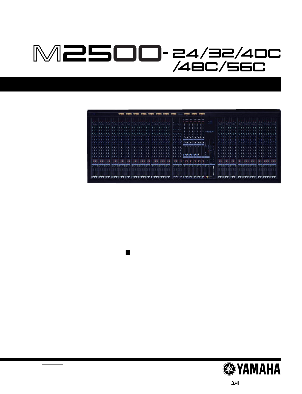
M2500
MIXING CONSOLE
SERVICE MANUAL
M2500-56C
CONTENTS
SPECIFICATIONS .............................................. 3/5
DIMENSIONS ............................................................ 8
PANEL LAYOUT ..................................... 9
CIRCUIT BOARD LAYOUT .............. 16
DISASSEMBLY PROCEDURE ............................ 18
LSI PIN DESCRIPTION .............................. 26
IC BLOCK DIAGRAM ................................... 30
CIRCUIT BOARDS ....................................... 33
INSPECTIONS ....................................................... 61/69
TEST PROGRAM ............................. 76/78
ERROR MESSAGES ....................... 80/81
MIDI IMPLEMENTATION CHART ......................................... 82
CIRCUIT DIAGRAMS
PARTS LIST
011484
PA
M2500-24 20000220-850000
M2500-32 20000220-1000000
M2500-40C 20000220-1150000
1/2
M2500-48C 20000220-1300000
M2500-56C 20000220-1450000
PW3000MA 20000220-100000
HAMAMATSU, JAPAN
1.50K-5972 Printed in Japan 2000.02
1
M2500
IMPOR TANT NOTICE
This manual has been provided for the use of authorized Yamaha Retailers and their service personnel. It has been assumed
that basic service procedures inherent to the industry, and more specifically Yamaha Products, are already known and understood by the users, and have therefore not been restated.
WARNING : Failure to follow appropriate service and safety procedures when servicing this product may result in per-
IMPORTANT : This presentation or sale of this manual to any individual or firm does not constitute authorization certifi-
The data provided is belived to be accurate and applicable to the unit(s) indicated on the cover. The research engineering, and
service departments of Yamaha are continually striving to improve Yamaha products. Modifications are, therefore, inevitable
and changes in specification are subject to change without notice or obligation to retrofit. Should any discrepancy appear to
exist, please contact the distributor’s Service Division.
WARNING : Static discharges can destroy expensive components. Discharge any static electricity your body may have
IMPORTANT : Turn the unit OFF during disassembly and parts replacement. Recheck all work before you apply power
sonal injury, destruction of expensive components and failure of the product to perform as specified. For
these reasons, we advise all Yamaha product owners that all service required should be performed by an
authorized Yamaha Retailer or the appointed service representative.
cation, recognition of any applicable technical capabilities, or establish a principal-agent relationship of
any form.
accumulated by grounding yourself to the ground bus in the unit (heavy gauge black wires connect to
this bus.)
to the unit.
LITHIUM BA TTERY HANDLING
This product uses a lithium battery for memory back-up.
WARNING : Lithium batteries are dangerous because they can be exploded by improper handling. Observe the following pre-
Leave lithium battery replacement to qualified service personnel.
Always replace with batteries of the same type.
When installing on the PC board by soldering, solder using the connection terminals provided on the battery cells.
Never solder directly to the cells. Perform the soldering as quickly as possible.
Never reverse the battery polarities when installing.
Do not short the batteries.
Do not attempt to recharge these batteries.
Do not disasemble the batteries.
Never heat batteries or throw them into fire.
ADVARSEL!
Lithiumbatteri-Eksplosionsfare ved fejlagtig handtering. Udskiftning ma kun ske med batteri af samme fabrikat og type. lever det brugte
batteri tilbage til leverandren.
VARNING
Explosionsfara vid felaktigt batteribyte.
Anvand samma batterityp eller en ekvivalent typ som rekommenderas av apparattillverkaren.
Kassera anvant batteri enligt fabrikantens instruktion.
VAROITUS
Paristo voi rajahtaa, jos se on virheellisesti asennettu.
Vaihda paristo ainoastaan laitevalmistajan suosittelemaan tyyppiiin.
Havita kaytetty paristo valmistajan ohjeiden mukaisesti.
The following information complies with Dutch official Gazette 1995. 45; ESSENTIALS OF ORDER ON THE COLLECTION OF BATTERIES.
• Please refer to the diassembly procedure for the removal of Back-up Battery.
• Leest u voor het verwijderen van de backup batterij deze beschrijving.
cautions when handling or replacing lithium batteries.
WARNING: CHEMICAL CONTENT NOTICE!
The solder used in the production of this product contains LEAD. In addition, other electrical/electronic and/or plastic (Where
applicable) components may also contain traces of chemicals found by the California Health and Welfare Agency (and possibly
other entities) to cause cancer and/or birth defects or other reproductive harm.
DO NOT PLACE SOLDER, ELECTRICAL/ELECTRONIC OR PLASTIC COMPONENTS IN YOUR MOUTH FOR ANY REASON WHAT
SO EVER!
Avoid prolonged, unprotected contact between solder and your skin! When soldering, do not inhale solder fumes or expose
eyes to solder/flux vapor!
If you come in contact with solder or components located inside the enclosure of this product, wash your hands before handling
food.
WARNING
Components having special characteristics are marked and must be replaced with parts having specification equal to those
originally installed.
2
SPECIFICATIONS
M2500
General specifications
0 dB is referenced to 0.775 Vrms.
Total Harmonic Distortion Less than 0.1% (THD+N)
(Master output) 20 Hz–20 kHz @ +14 dB 600 Ω
Frequency Response 0+1, –3 dB
(Master Output) 20 Hz–20 kHz @ +4 dB 600 Ω
Hum & Noise (20 Hz–20 kHz)*1
Rs= 150 Ω –99 dB Residual Output Noise.
Input Gain= Max.
Input Pad= OFF
||
Input sensitivity= –60 dB
–64 dB(68 dB S/N) STEREO OUT Master Level control and
–80 dB(84 dB S/N) STEREO OUT, MONO/C OUT Master f ader
–81 dB(85 dB S/N) GROUP1/AUX7–GROUP8/AUX14 OUT
–75 dB(79 dB S/N) AUX1–6, AUX7/GROUP1–AUX14/GROUP8
–90 dB(94 dB S/N) MATRIX OUT Master level control at nomi-
Crosstalk –70 dB @ 1 kHz adjacent inputs.
–70 dB @ 1 kH input to output. (CH INPUT)
–50 dB @ 1 kHz input to output. (ST CH INPUT)
Maximum Voltage Gain
GROUP/AUX FLIP SW= off
60 dB CH INPUT to CH INSERT OUT
84 dB CH INPUT to GROUP1/AUX7–GROUP8/
80 dB CH INPUT to AUX1, 2 OUT(Pre Fader)
90 dB CH INPUT to AUX3–6, AUX7/GROUP1–
84 dB CH INPUT to STEREO OUT(CH to ST)
70 dB CH INPUT to MONITOR OUT(PFL)
CH INPUT PAD SW 26 dB
CH INPUT GAIN control 44 dB variable
ST CH 1A, 2–4 INPUT GAIN control
ST CH 1B INPUT GAIN control
CH INPUT High Pass Filter 18 dB/octave
CH INPUT Equalization
+15, –15 dB maximum
HIGH 10 kHz (shelving)
HIGH-MID 400– 8 kHz (peaking)
LOW-MID 80–1.6 kHz (peaking)
LOW 100 Hz (shelving)
Gain control at minimum level
–128 dB Equivalent Input Noise.
(STEREO OUT, MONO/C OUT,
GROUP/AUX OUT, AUX OUT,
AUX/GROUP OUT)
one Ch fader at nominal level.
at nominal level and all Ch assign SW’s off
and all GROUP to ST SW’s off.
Master Level control at nominal lev el and all
Ch assign SW’s off.
GROUP/AUX FLIP SW off.
OUT Master Level control at nominal level
and all Ch send controls at minimum.
GROUP/AUX FLIP SW off.
nal level and all Matrix Mix controls at minimum level.
AUX14 OUT
AUX14/GROUP8 OUT(Post Fader)
40 dB variable
30 dB variable
roll-off below 80 Hz at –3 dB point.
ST CH INPUT Equalization
+15, –15 dB maximum
Phantom Power +48 VDC is applied to balanced inputs (via
CH LED Indicators
ST CH LED Indicators
Oscillator/Noise Switchable sine wave @ 100 Hz, 1 kHz or
Scene Memory Direct Scene Memory recall switches (1–8)
VU Meters 11 illuminated meters
VU Meter Peak Indicators LED(red) built into each VU meter turns on
Dimension Heigt 265 mm
Weight 102kg(56C), 93kg(48C), 84kg(40C),
*1 Hum & Noise are measured with a 6 dB/octave filter @ 12.7 kHz;
equivalent to a 20 kHz filter with infinite dB/octave attenuation.
For European Model
Purchaser/User information specified in EN55103-1 and EN55103-2.
Conformed Enviroment: E1, E2, E3 and E4.
PEAK LED(red) built into each CH INPUT turns on
NOM LED(yellow) b uilt into each CH INPUT turns
SIGNAL LED(green) built into each CH INPUT turns
PEAK LED(red) built into each ST CH INPUT turns
NOM LED(yellow) built into each ST CH INPUT
SIGNAL LED(green) built into each ST CH INPUT
#1 ; GROUP1/AUX7
#2 ; GROUP2/AUX8
#3 ; GROUP3/AUX9
#4 ; GROUP4/AUX10
#5 ; GROUP5/AUX11
#6 ; GROUP6/AUX12
#7 ; GROUP7/AUX13
#8 ; GROUP8/AUX14
#9 ; STEREO L
#10 ; MONO/C
#11 ; STEREO R
Depth 875 mm (except rear connectors)
Width 2385 mm(56C), 2142 mm(48C),
HIGH 10 kHz (shelving)
LOW 100 Hz (shelving)
6.8 kΩ current-limiting/isolation resistors) for
powering condenser microphones; may be
turned ON or OFF via rear-panel phantom
Master switch.
When Master is ON, individual channels
may be turned ON or OFF via +48V
switches (with red LED) on each input channel.
when pre-Fader level reaches +17 dB.
on when pre-Fader level reaches 0 dB.
on when pre-Fader level reaches –13 dB.
on when pre-Fader [L+R] level reaches
+17 dB.
turns on when pre-Fader [L+R] level
reaches 0 dB.
turns on when pre-Fader [L+R] level
reaches –13 dB.
10 kHz, or pink noise.
Switchable Scene Memory recall (1–128)
(0VU= +4 dB output @ 600Ω load)
•
AUX1•AUX7/GROUP1•MATRIX1
•
AUX2•AUX8/GROUP2•MATRIX2
•
AUX3•AUX9/GROUP3•MATRIX3
•
AUX4•AUX10/GROUP4•MATRIX4
•
AUX5•AUX11/GROUP5•MATRIX5
•
AUX6•AUX12/GROUP6•MATRIX6
•
NONE•AUX13/GROUP7•MATRIX7
•
NONE•AUX14/GROUP8•MATRIX8
•
PFL/AFL L
•
PFL/AFL R
when output signal is above the level 3 dB
lower than clipping level.
1899 mm(40C), 1642 mm(32),
1400 mm(24)
71kg(32), 62kg(24)
3
M2500
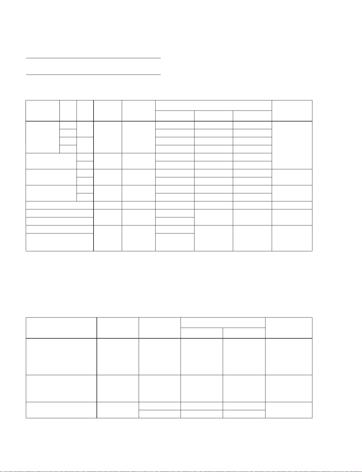
Input/output characteristics
Input specifications
Connection PAD
CH INPUT
*8
(1–n)
ST CH 1A INPUT
[L, R]
ST CH 1B INPUT
[L, R]
ST CH INPUT
[L, R] (2–4)
*9
Input Level
Nominal Max before Clip
Gain
Actual Load
Trim
Impedance
0
–60
26 –54 dB(1.55 mV) –34 dB(15.5 mV) –14 dB(155 mV)
0
–16
26 –10 dB(245 mV) +10 dB(2.45 V) +30 dB(24.5 V)
–30
+10 –10 dB(245 mV) +10 dB(2.45 V) +30 dB(24.5 V)
–20
+10 –10 dB(245 mV) +10 dB(2.45 V) +30 dB(24.5 V)
–30
+10 –10 dB(245 mV) +10 dB(2.45 V) +30 dB(24.5 V)
3 kΩ
5 kΩ 600 Ω Lines
10 kΩ 600 Ω Lines
5 kΩ 600 Ω Lines
For Use With
Nominal
50–600 Ω Mics
&
600 Ω Lines
Sensitivity
–80 dB(0.078 mV) –60 dB(0.775 mV) –40 dB(7.75 mV)
–36 dB(12.3 mV) –16 dB(123 mV) +4 dB(1.23 V)
–50 dB(2.45 mV) –30 dB(24.5 mV) –10 dB(245 mV)
–40 dB(7.75 mV) –20 dB(77.5 mV) 0 dB(0.775 V)
–50 dB(2.45 mV) –30 dB(24.5 mV) –10 dB(245 mV)
*1
Connector In
Mixer
XLR-3-31 type
Phono Jack
Phone Jack(TRS)
TALKBACK IN 10 kΩ 50–600 Ω Mics –66 dB(0.388 mV) –50 dB(2.45 mV) –20 dB(77.5 mV) XLR-3-31 type
MATRIX SUB IN [L, R]
STEREO [L, R] MONO/C SUB IN –6 dB(388 mV)
CH INSERT IN (1–n)
*8
STEREO [L, R] MONO/C INSERT IN
GRP/AUX INSERT IN (1/7–8/14)
10 kΩ 600 Ω Lines
10 kΩ 600 Ω Lines
–2 dB(0.616 V)
–26 dB(38.8 mV)
–10 dB(245 mV)
+4 dB(1.23 V) +24 dB(12.3 V) Phone Jack(TRS)
0 dB(0.775 V) +20 dB(7.75 V) Phone Jack(TRS)
AUX INSERT IN (1–6)
*1 0 dB=0.775 Vrms.
*2 Balanced.
*3 Unbalanced.
*4 Balanced (T=HOT, R=COLD, S=GND).
*5 Unbalanced.
*6 Unbalanced (T=SIGNAL, R=GND, S=GND).
*7 Unbalanced (T=OUTPUT, R=INPUT, S=GND).
*8 n=56, 48, 40, 32 or 24
*9 Sensitivity is the lowest level that will produce an output of +4 dB(1.23 V), or the nominal output level when the unit is set to maximum level.
*2
*3
*4
*5
*6
*7
Output specifications
Connection
STEREO OUT [L, R]
MONO/C OUT
GRP/AUX OUT (1/7–8/14)
AUX/GRP OUT (7/1–14/8)
AUX OUT (1–6)
MONITOR OUT [L, R, MONO/C]
MATRIX OUT (1–8)
CH INSERT OUT (1–n)
STEREO INSERT OUT [L, R]
MONO/C INSERT OUT
GRP/AUX INSERT OUT (1/7–8/14)
AUX INSERT IN (1–6)
PHONES OUT [L, R] 100 Ω
*1 0 dB=0.775 Vrms.
*2 Balanced.
*3 Unbalanced (T=OUTPUT, R=INPUT, S=GND).
*4 Unbalanced.
*5 n=56, 48, 40, 32 or 24
4
*5
Actual Source
Impedance
For Use With
Nominal
Output Level
Nominal Max before Clip
*1
Connector In Mixer
150 Ω 600 Ω Lines +4 dB(1.23 V) +24 dB(12.3 V) XLR-3-32 type
600 Ω 10 kΩ Lines 0 dB(0.775 V) +20 dB(7.75 V) Phone Jack(TRS)
8 Ω Phones 10 mW 20 mW
40 Ω Phones 30 mW 75 mW
Stereo Phone Jack
*2
*3
*4
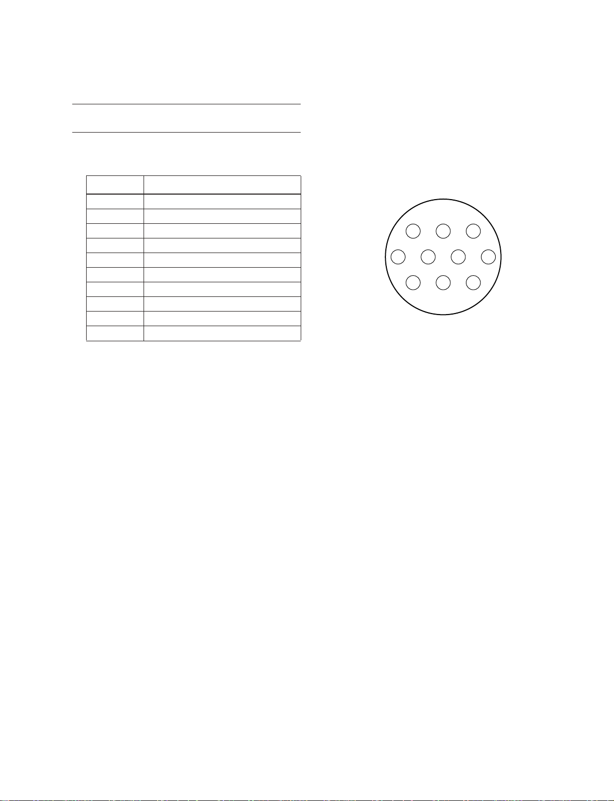
Other
Connector wiring
Pin No. Signal name
1 Power supply remote
2 +15 V
3 ±15 V GND
4 +48 V GND
5 –15 V
6 +12 V
7 +12 V GND / power supply remote
8 Power supply remote
9 +48 V
10 FRAME GND
M2500
3 2 1
7 6 5 4
10 9 8
Included items
Power supply connection cable (3 m, 10 pin)
7
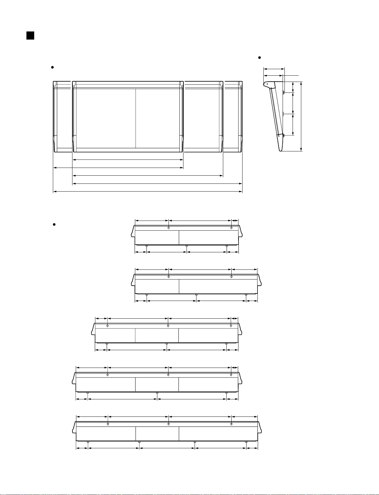
M2500
DIMENSIONS
Front
1400: M2500-24
1642: M2500-32
1899: M2500-40C
2142: M2500-48C
2385: M2500-56C
Side
265
23242
137270270
875
Rear
792422 88
55 55
55 55
55 55
55 55
847 847
968 968
597 597
792422 331
718 718
792768154 88
792768399 88
M2500-24
M2500-32
M2500-40C
M2500-48C
792768399 331
M2500-56C
55 55
8
740 740700
Units :mm
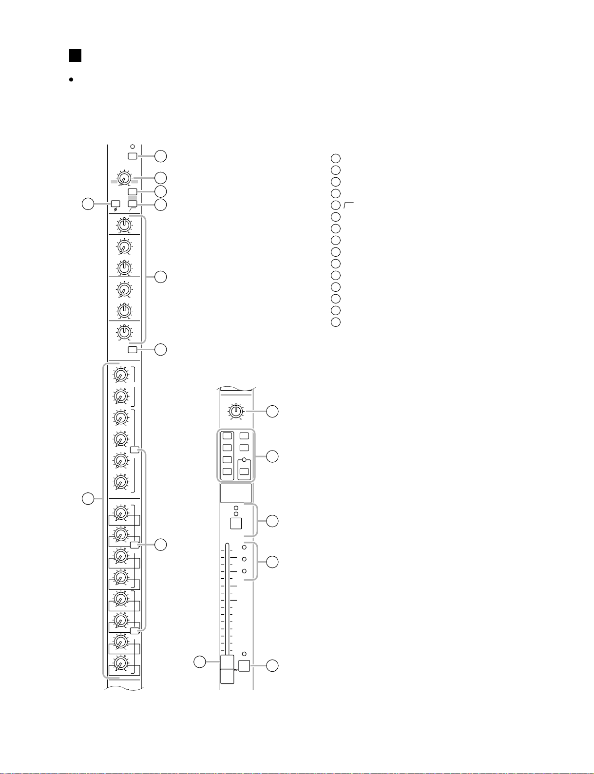
PANEL LAYOUT
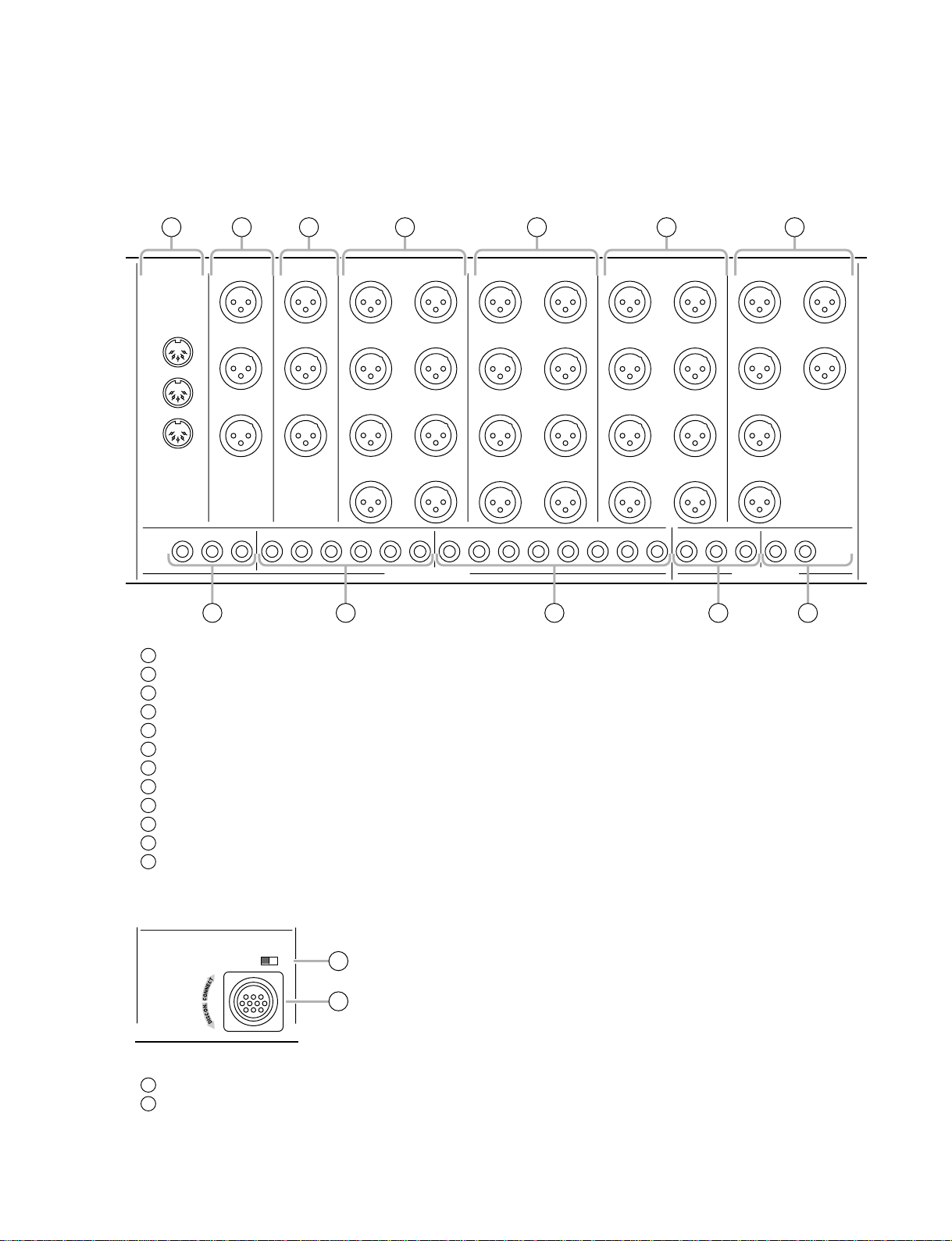
Control panel
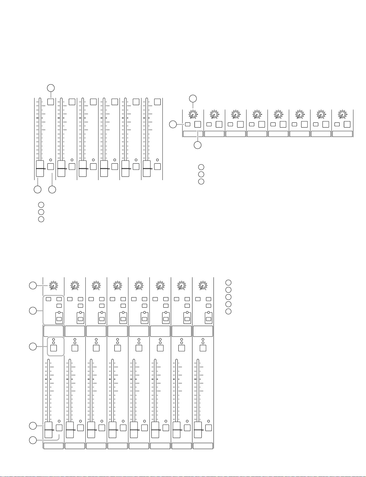
Input channel section
Monaural input channels
M2500
EQ
PRE
PRE
PRE
1
2
–34
3
5
80
6
7
010
AUX14
PAN
LCR
ODD EVEN
1-2
MONO
3-4
5-6
7-8
CHECK
ON
10
ST
11
LCR
12
ON/EDIT
9
14
10
PEAK
5
SIGNAL
0
5
10
20
30
40
50
60
NOM
PFL
13
15
+48V
GAIN
+10
–16 –60
26dB
4
HI
–15 +15
HI-MID
400 8k
–15 +15
LO-MID
80 1.6k
–15 +15
LO
–15 +15
010
AUX1 PRE
010
AUX2
010
AUX3
010
AUX4
010
AUX5
010
AUX6
8
010
AUX7
010
AUX8
010
AUX9
010
AUX10
010
AUX11
010
AUX12
010
AUX13
010
AUX14
PAN
C
+48 V (phantom power) switch
1
GAIN control
2
26 dB pad switch
3
φ
(phase) switch
4
(high pass filter) switch
5
80
EQ controls
6
EQ switch
7
AUX 1–AUX 14 controls
8
PRE switches
9
PAN control
10
Channel assign switches
11
ON/EDIT switch / ON, CHECK indicators
12
PEAK/NOM/SIGNAL indicators
13
Channel fader
14
PFL (pre-fader listen) switch
15
9
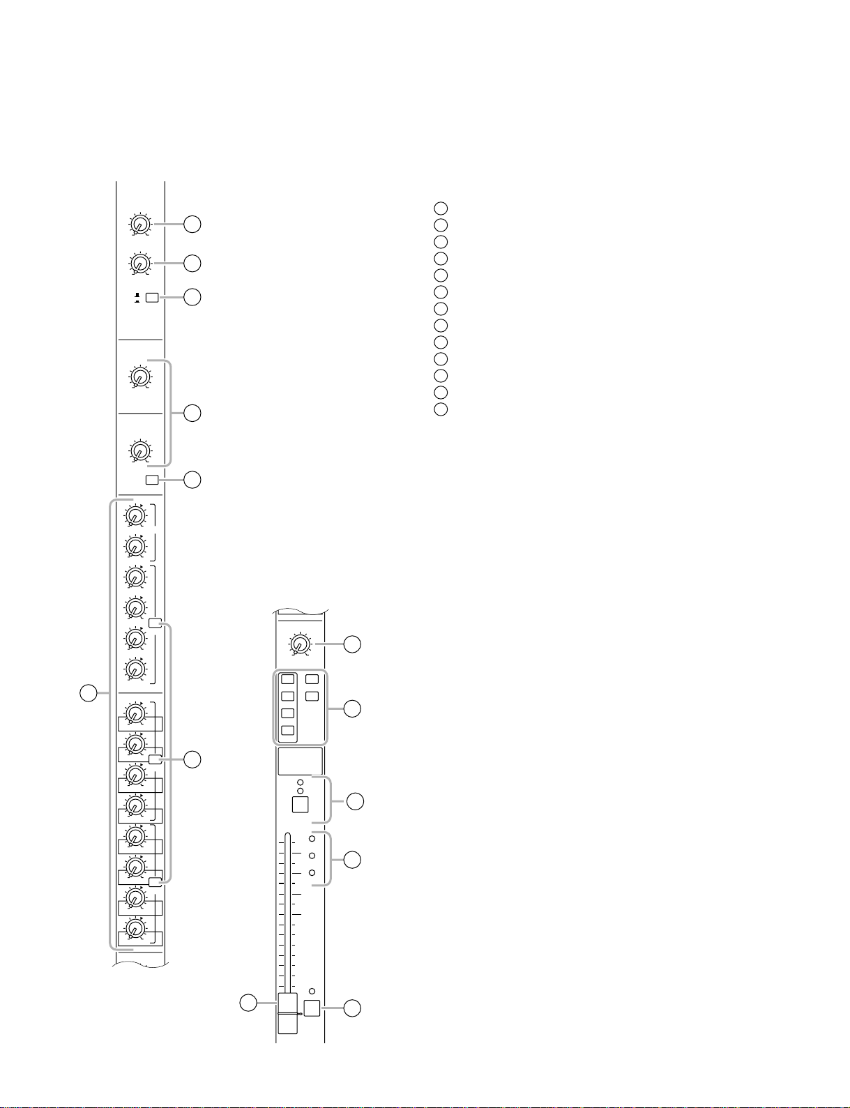
M2500
Stereo input channels
GAIN
A
+10 –30
B
+10 –20
HI
–15 +15
LO
GAIN A control
1
GAIN B control
1
2
A
B
3
4
2
A/B switch
3
EQ controls
4
EQ switch
5
AUX 1–AUX 14 controls
6
PRE switches
7
BAL control
8
Channel assign switches
9
ON/EDIT switch / ON, CHECK indicators
10
PEAK/NOM/SIGNAL indicators
11
Channel fader
12
PFL (pre-fader listen) switch
13
–15 +15
5
EQ
010
AUX1 PRE
010
AUX2
010
AUX3
010
010
AUX4
PRE
010
AUX5
010
AUX6
6
010
AUX7
010
AUX8
010
AUX9
010
AUX10
010
AUX11
010
AUX12
010
AUX13
010
AUX14
BAL
LCR
ODD EVEN
PRE
PRE
7
12
AUX14
BAL
LR
ODD EVEN
1-2
3-4
5-6
7-8
ON/EDIT
10
5
SIGNAL
0
5
10
20
30
40
50
60
ST
MONO
CHECK
ON
PEAK
NOM
PFL
8
9
10
11
13
10
M2500
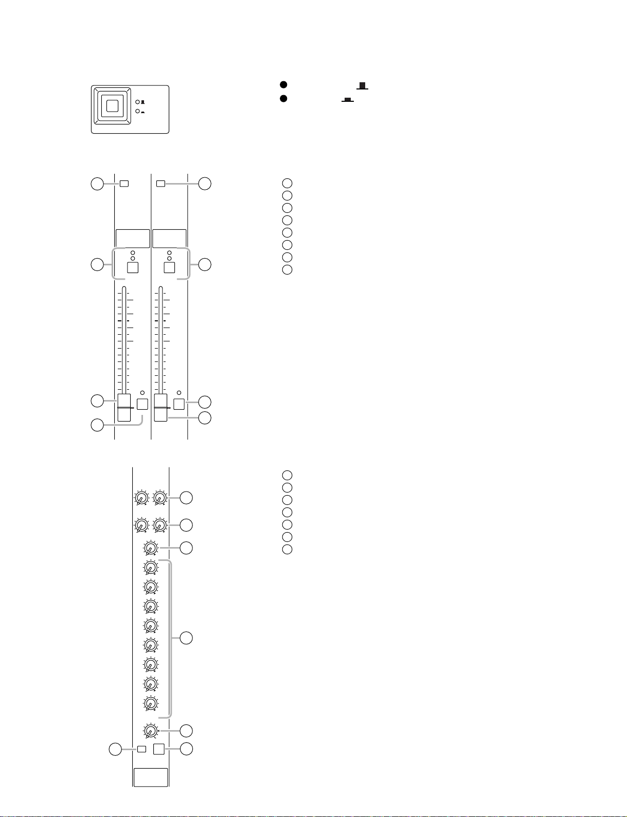
GROUP/AUX master section
AUX 1-6 section
1
10
5
0
5
10
20
30
40
50
60
AUX1
2
ON switches
1
AUX 1–6 master faders
2
AFL (after fader listen) switches
3
10
ON
5
0
5
10
20
30
40
50
60
AFL
AUX2
10
ON
5
0
5
10
20
30
40
50
60
AFL
AUX3
10
ON
5
0
5
10
20
30
40
50
60
AFL
AUX4
3
A7/G1-A14/G8 section
10
ON
5
0
5
10
20
30
40
50
60
AFL
AUX5
10
ON
AFL
ON
5
0
5
10
20
30
40
50
60
2
AFL
AUX6
1
010
LEVEL
ON
AFL
A7 / G1
010
LEVEL
ON
AFL
A8 / G2
3
LEVEL control
1
ON switch
2
AFL switch
3
010
LEVEL
ON
AFL
A9 / G3
010
LEVEL
ON
AFL
A10 / G4
010
LEVEL
ON
AFL
A11 / G5
010
LEVEL
ON
AFL
A12 / G6
010
LEVEL
ON
AFL
A13 / G7
010
LEVEL
ON
AFL
A14 / G8
G1/A7-G8/A14 section
PAN
4
MATRIX ST
5
6
7
8
G1 / A7
LCR
ON/EDIT
10
5
0
5
10
20
30
40
50
60
MONO
LCR
CHECK
ON
AFL
PAN
LCR
MATRIX ST
MONO
CHECK
ON
ON/EDIT
10
5
0
5
10
20
30
40
50
60
G2 / A8
LCR
AFL
PAN
LCR
MATRIX ST
MONO
CHECK
ON
ON/EDIT
10
5
0
5
10
20
30
40
50
60
G3 / A9
LCR
AFL
PAN
LCR
MATRIX ST
MONO
CHECK
ON
ON/EDIT
10
5
0
5
10
20
30
40
50
60
G4 / A10
LCR
AFL
PAN
LCR
MATRIX ST
MONO
CHECK
ON
ON/EDIT
10
5
0
5
10
20
30
40
50
60
G5 / A11
LCR
AFL
PAN
LCR
MATRIX ST
MONO
CHECK
ON
ON/EDIT
10
5
0
5
10
20
30
40
50
60
G6 / A12
LCR
AFL
PAN
LCR
MATRIX ST
MONO
CHECK
ON
ON/EDIT
10
5
0
5
10
20
30
40
50
60
G7 / A13
LCR
AFL
PAN
LCR
MATRIX ST
MONO
CHECK
ON
ON/EDIT
10
5
0
5
10
20
30
40
50
60
G8 / A14
LCR
AFL
PAN control
4
Channel assign switches
5
ON/EDIT switch / ON, CHECK indicators
6
Fader
7
AFL (after fader listen) switch
8
11
M2500
GROUP/AUX FLIP switch
GROUP
AUX
GROUP/AUX FLIP
Stereo/monaural master section
STEREO section MONO/C section
1
2
MATRIX MATRIX
CHECK
ON
CHECK
ON
ON/EDITON/EDIT
5
6
When GROUP ( ) is selected
When AUX ( ) is selected
MATRIX switch
1
ON/EDIT switch / ON, CHECK indicators
2
Fader
3
AFL switch
4
MATRIX switch
5
ON/EDIT switch / ON, CHECK indicators
6
Fader
7
AFL switch
8
10
5
0
5
10
20
30
40
50
3
60
4
Matrix section
AFL
SUB IN
ST
0
MONO/C
0
G1 / A7
0
G2 / A8
0
G3 / A9
0
G4 / A10
0
G5 / A11
0
G6 / A12
0
G7 / A13
0
G8 / A14
10
5
0
5
10
20
30
40
50
60
8
AFL
7
MONO/CSTEREO
SUB IN L/R control
1
ST L/R controls
2
0L0
0L0
1
R
2
R
3
MONO/C control
3
G1/A7–G8/A14 controls
4
LEVEL control
5
ON switch
6
AFL switch
7
4
12
010
LEVEL
6
ON
MATRIX 1
5
7
AFL
M2500
G1-8/A7-14
AUX1-6
A7-14/G1-8
MATRIX
METER
SELECT
1
2
3
4
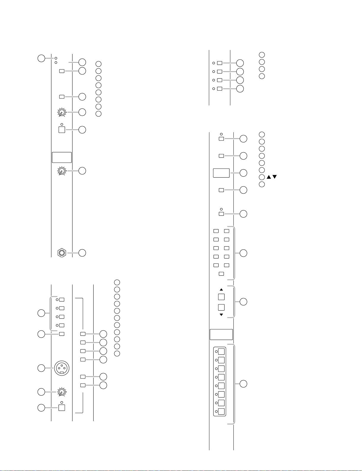
Monitor section
1
INPUT
MASTER
MASTER
PFL
L+R
010
LEVEL
ON
MONITOR
010
PHONES
Meter select section
MATRIX switch
1
A7-14/G1-8 switch
2
3
4
5
INPUT indicator
1
MASTER indicator
2
MASTER PFL switch
3
L+R switch
4
LEVEL control
5
ON switch
6
PHONES (headphone) control
7
PHONES jack
8
2
AUX 1-6 switch
3
G1-8/A7-14 switch
4
Control section
6
UTILITY
RECALL
7
MEMORY
STORE
CHECK
1
2
3
4
5
UTILITY switch
1
RECALL switch
2
MEMORY display
3
STORE switch
4
CHECK switch
5
0–9/ENTER switches
6
/ switches
7
DIRECT RECALL 1–8 switches
8
8
Talkback/oscillator section
PINK
1
2
10kHz
1kHz
100Hz
ON
OSCILLATOR
AUX1-2
AUX3-6
AUX7-10
AUX11-14
3
ST
MONO/C
4
5
MIC
010
TB/OSC
ON
TALKBACK
6
7
8
9
10
11
OSCILLATOR select switches
1
OSCILLATOR ON switch
2
MIC jack
3
TB/OSC control
4
ON switch
5
AUX 1-2 switch
6
AUX 3-6 switch
7
AUX 7-10 switch
8
AUX 11-14 switch
9
ST switch
10
MONO/C switch
11
1 2
3 4
5 6
7 8
9
ENTER
SCENE
MEMORY
DIRECT
RECALL
CONTROL
6
0
7
1
2
3
4
8
5
6
7
8
13
M2500
+
3
0
1
3
PEAK
V
7
10
20
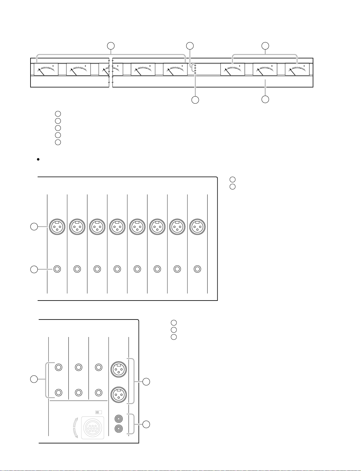
Meter bridge
PEAK
357
1
0
10
20
3
+
VU
1
2
3
4
5
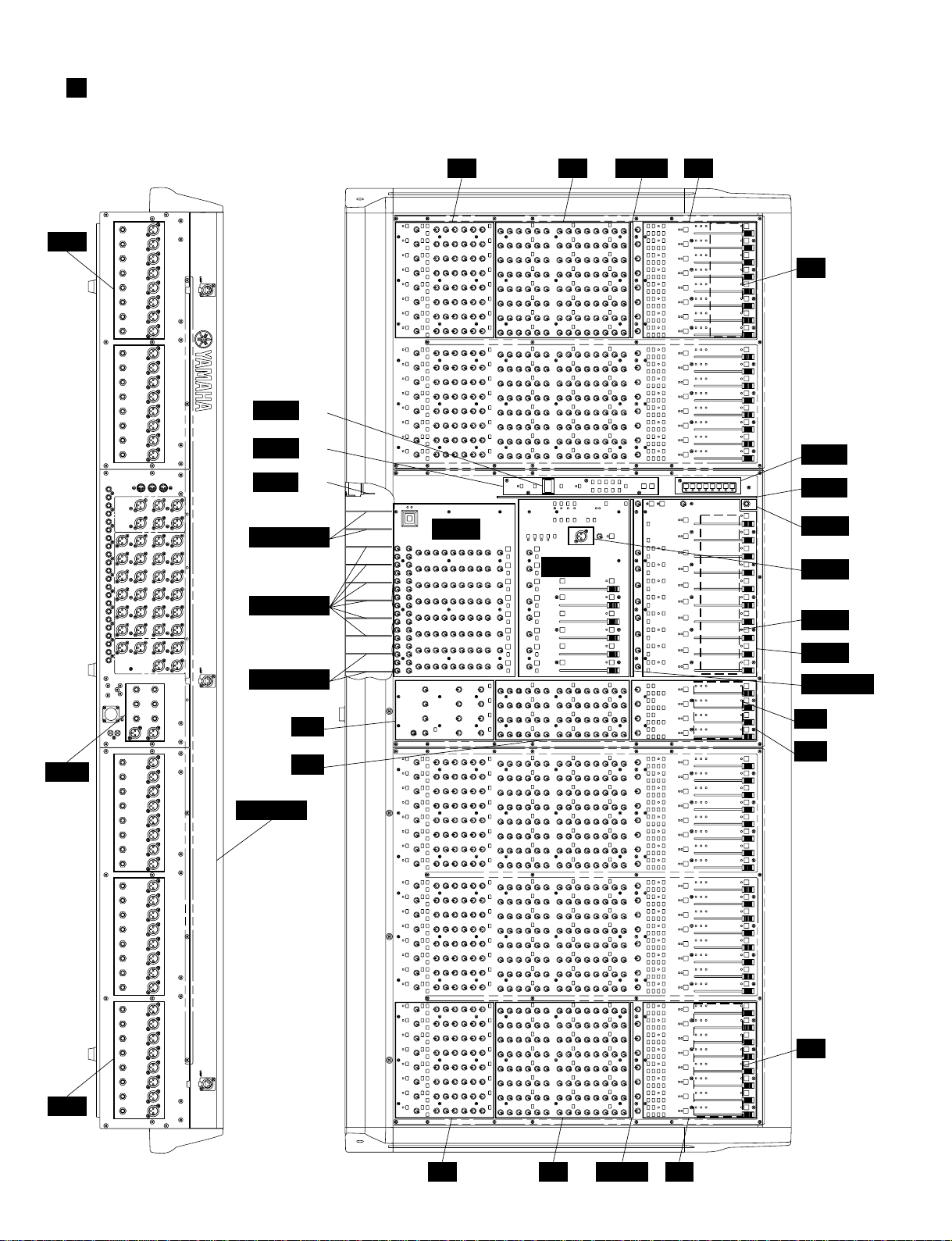
Rear panel
PEAK
357
1
0
10
20
3
+
VU
1/7–8/14 level meters
+15V/–15V/+12V indicators
PHANTOM MASTER indicator
STEREO, PFL/AFL level meters
MONO/C level meter
1 2 4
Monaural input channel input/output jacks
24
INPUT
23
INPUT
22
INPUT
21
INPUT
INPUT
–
10
20
STEREO R
PFL/AFL R
PEAK
357
1
0
3
+
VU
PEAK
357
1
0
10
20
3
+
VU
PEAK
357
10
20
VU
8/147/132/81/7
+15V
1
0
3
–15V
+12V
+
PHANTOM MASTER
20
10
PFL/AFL L
PEAK
357
1
0
3
+
VU
3
INPUT jacks
1
INSERT I/O jacks
2
20
19
INPUT
18
INPUT
17
INPUT
PEAK
357
1
0
10
20
3
+
VU
MONO/CSTEREO L
5
1
INSERT
I/O
I/O
INSERT
0
dB
INSERT
0
dB
I/O
INSERT
0
dB
I/O
INSERT
0
dB
2
Stereo input channel input/output jacks
INPUT
R
ST CH 1
INPUT A
L
R
ST CH 4
ST CH 3
INPUT
L/MONO
5
L/MONO
R
ST CH 2
INPUT
L/MONO
R
I/O
I/O
INSERT
0
dB
INSERT
0
dB
3
4
5
INSERT
I/O
I/O
0
0
dB
dB
INPUT A jacks
INPUT B jacks
INPUT jacks
3
PHANTOM
MASTER
OFF ON
INPUT B
L
4
READ OWNER’S MANUAL
R
DC POWER INPUT
14
Master section input/output jacks
M2500
12
MIDI
IN
OUT
THRU
6 5 4 3
MONITOR
OUT
+4
dB
L
MONO
/C
R
ST OUT
+4
MONO
11 10
AUX OUT jacks
1
GRP/AUX OUT jacks
2
AUX/GRP OUT jacks
3
MATRIX OUT jacks
4
ST OUT, MONO/C OUT jacks
5
MONITOR OUT jacks
6
SUB IN MATRIX jacks
7
SUB IN ST L/R, MONO/C jack
8
INSERT I/O G1/A7–G8/A14 jacks
9
INSERT I/O AUX jacks
10
INSERT I/O ST L/R, MONO jacks
11
MIDI connectors
12
dB
L
/C
R
AUX
MATRIX OUT
123456
INSERT I/O
2 1
+4
dB
15
26
37
48
+4
dB
AUX/GRP OUT
A11/
G6
A12/
G6
A13/
G7
A14/
G8
+4
dB
A7/
G1
A8/
G2
A9/
G3
A10/
G4
GRP/AUX OUT
G5/
A11
G6/
A12
G7/
A13
G8/
A14
+4
dB
G1/
A7
G2/
A8
G3/
A9
G4/
A10
AUX OUT
ST LMONO/CST RST LMONO/CST R G1/A7G2/A8G3/A9G4/A10G5/A11G6/A12G7/A13G8/A14
SUB IN
+4
dB
13
24
5
6
MATRIX
LR
+4
dB
9 8 7
PHANTOM
MASTER
OFF ON
READ OWNER’S MANUAL
PHANTOM MASTER switch
13
DC POWER INPUT connector
14
DC POWER INPUT
13
14
15
M2500
INJK
CIRCUIT BOARD LAYOUT
IN1 IN3IN2 INPAN
IN4
CTRL 3/5
STJK
CTRL 4/5
CTRL 5/5
MASOUT3
MASOUT4
MASOUT1
MASOUT
ST1
ST2
MAS1
MAS2 1/2
CTRL 2/5
CTRL 1/5
MAS3 2/2
MAS2 2/2
MAS4
MAS3 1/2
MASPAN
ST4
ST3
INJK
16
IN1 IN2 INPAN IN3
IN4
56CH
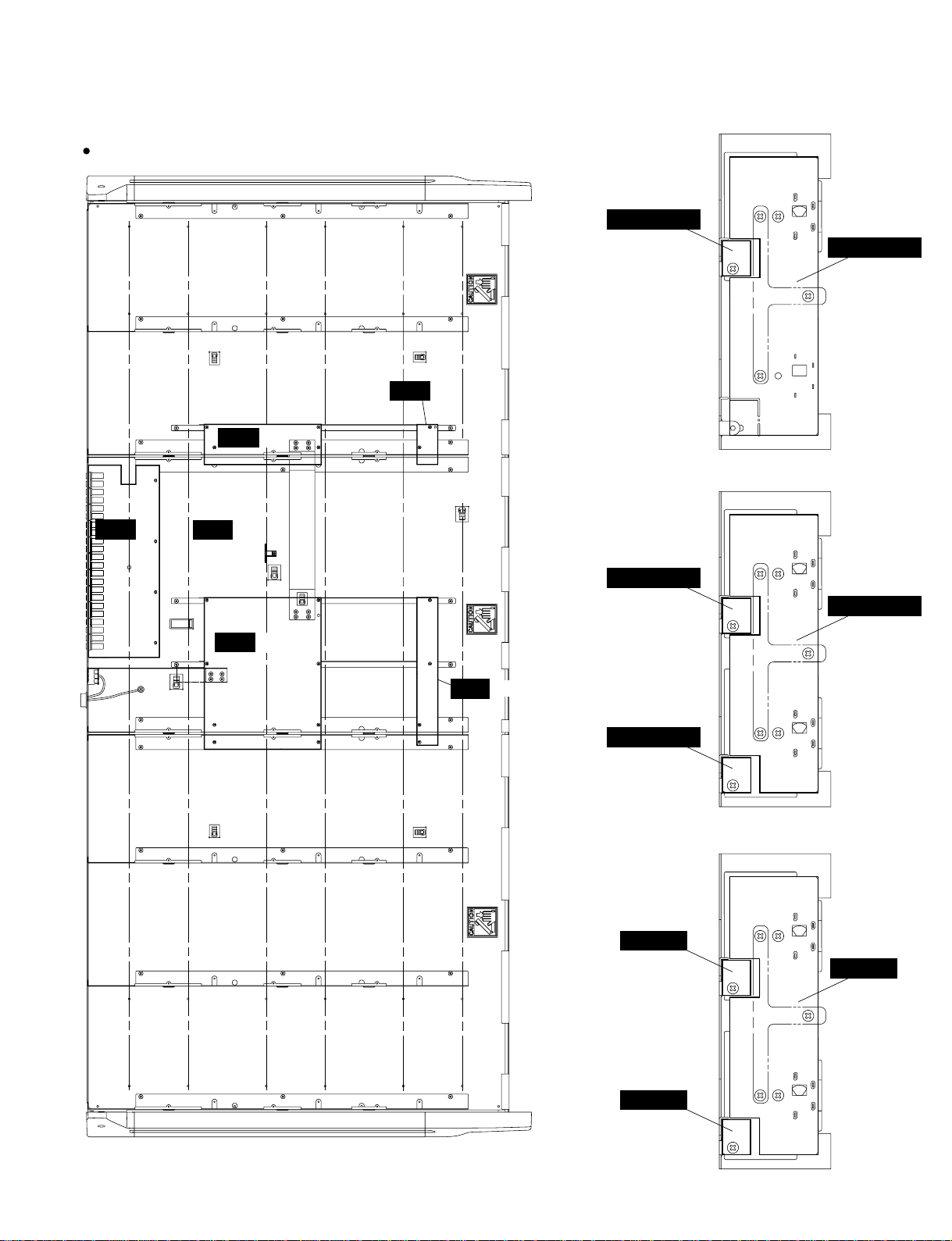
M2500-56C
ISRT 3/6
ISRT 5/6
METER2 2/2
2/3
M2500
METER2 2/2
1/3
ISRT 1/6
ISRT 6/6
ISRT 2/6
ISRT 4/6
METER2 1/2
2/3
METER2 1/2
3/3
METER1
2/3
METER2 1/2
1/3
METER1
1/3
METER1
3/3
17
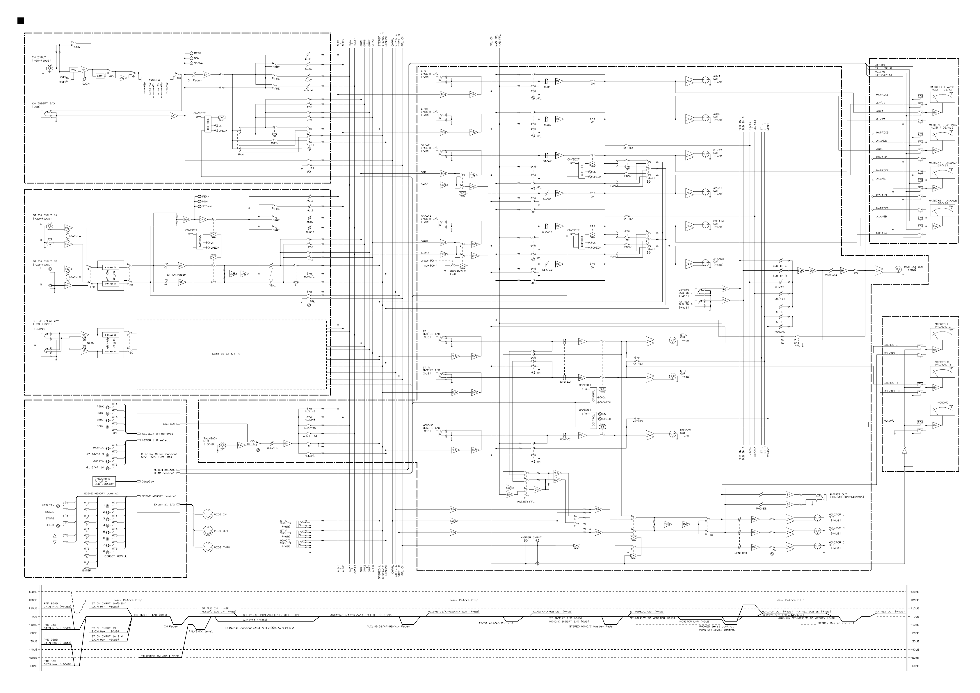
<P.2>M2500 BLOCK & LEVEL DIAGRAM
CH INPUT(IN
INPUT(ST
)
)
MASTER(MAS
)
METER
CONTROL
METER

CIRCUIT BOARDS
CONTENTS
MASOUT1 Circuit Board ......................................34
MASOUT2 Circuit Board.......................................35
MASOUT3 Circuit Board.......................................36
METER1 Circuit Board .........................................37
METER2 Circuit Board .........................................37
METER3 Circuit Board .........................................37
CTRL 1/5 Circuit Board ........................................38
CTRL 2/5 Circuit Board ........................................38
CTRL 3/5 Circuit Board ........................................38
CTRL 4/5 Circuit Board ........................................38
CTRL 5/5 Circuit Board ........................................38
IN1 Circuit Board ..................................................40
IN2 Circuit Board ..................................................42
IN3 Circuit Board ..................................................44
IN4 Circuit Board ..................................................46
IN JK Circuit Board ...............................................47
IN PAN Circuit Board ............................................47
ISRT 1/6 Circuit Board ..........................................48
ISRT 2/6 Circuit Board ..........................................49
ISRT 3/6 Circuit Board ..........................................49
ISRT 4/6 Circuit Board ..........................................48
ISRT 5/6 Circuit Board ..........................................48
ISRT 6/6 Circuit Board ..........................................48
MAS1 1/2 Circuit Board ........................................48
MAS1 2/2 Circuit Board ........................................48
MAS2 1/2 Circuit Board ........................................52
MAS2 2/2 Circuit Board ........................................52
MAS3 1/2 Circuit Board ........................................54
MAS3 2/2 Circuit Board ........................................54
MAS4 Circuit Board ..............................................56
MAS PAN Circuit Board ........................................56
ST1 Circuit Board .................................................57
ST2 Circuit Board .................................................58
ST3 Circuit Board .................................................59
ST4 Circuit Board .................................................60
STJK 1/2 Circuit Board .........................................60
STJK 2/2 Circuit Board .........................................60
M2500
Note : See parts list for details of circuit board component parts.
33
M2500
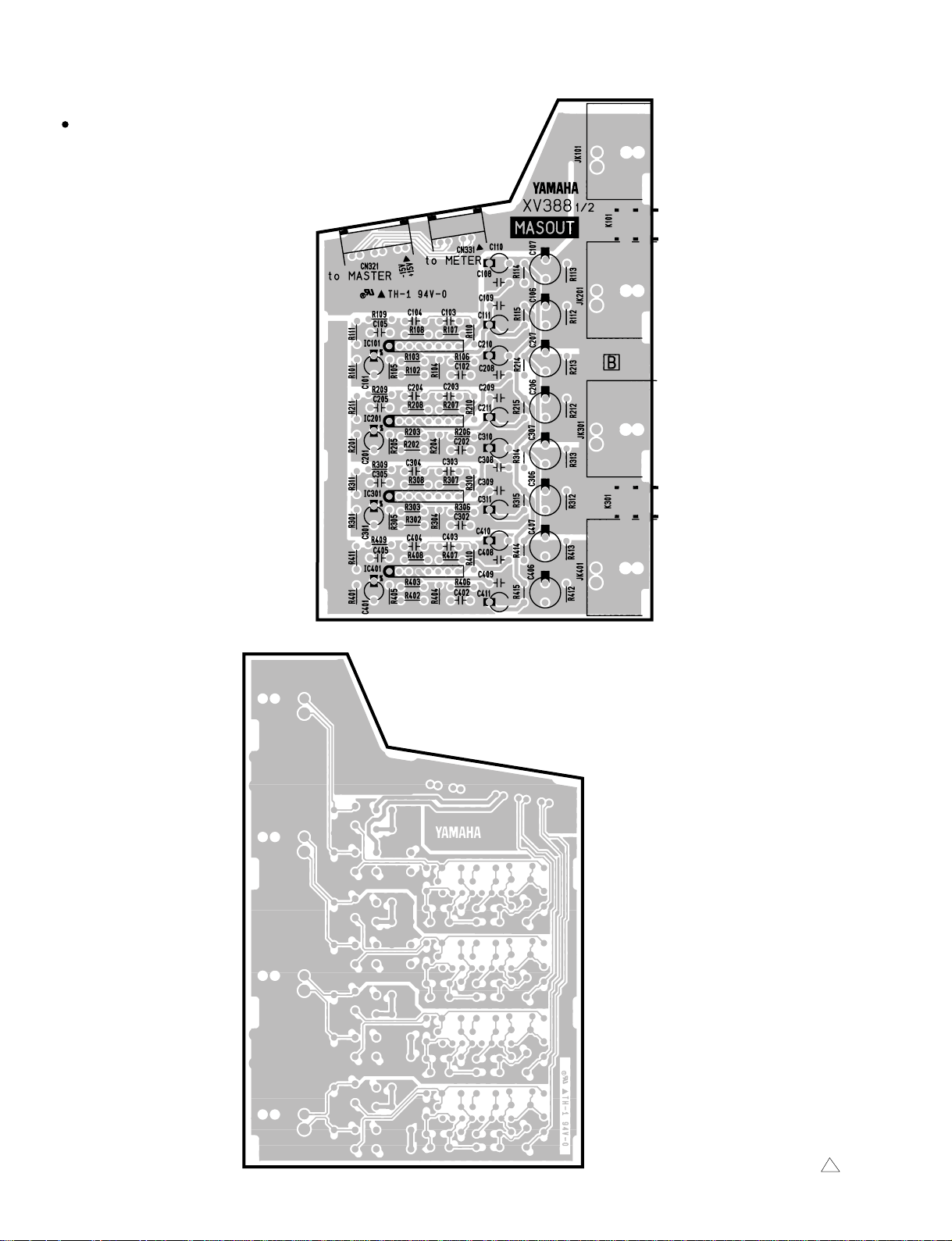
MASOUT1 Circuit Board
to METER1
-CN104
MATRIX OUT (5, 1)
AUX/GRP OUT (A11/G6, A7/G1)
GRP/AUX OUT (G5/A11, G1/A7)
AUX OUT (3)
CN321:
(AUX OUT 326)
MAS2-CN205
(AUX/GRP OUT A7/G1~A10/G4)
MAS2-CN206
(AUX/GRP OUT A11/G5~A14/G8)
MAS2-CN207
(GRP/AUX OUT G1/A7~G4/A10)
MAS3-CN308
(GRP/AUX OUT G5/A11~G8/A14)
MAS3-CN309
(MATRIX OUT 1~4)
MAS1-CN101
(MATRIX OUT 5~8)
MAS1-CN102
MATRIX OUT (6, 2)
AUX/GRP OUT (A12/G6, A8/G2)
GRP/AUX OUT (G6/A12, G2/A8)
AUX OUT (4)
MATRIX OUT (7, 3)
AUX/GRP OUT (A13/G7, A9/G3)
GRP/AUX OUT (G7/A13, G3/A9)
AUX OUT (5)
MATRIX OUT (8, 4)
AUX/GRP OUT (A14/G8, A10/G4)
GRP/AUX OUT (G8/A14, G4/A10)
AUX OUT (6)
Component side
34
Pattern side
MASOUT1 : 3NA-V230710 1
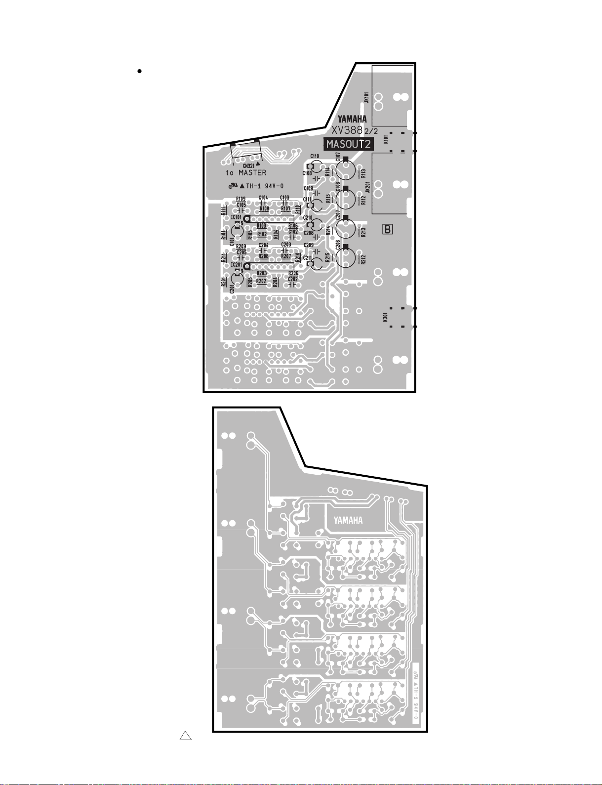
MASOUT2 Circuit Board
to MAS2
-CN204
M2500
AUX OUT
1
AUX OUT
2
Component side
MASOUT2 : 3NA-V230710 1
Pattern side
35
M2500
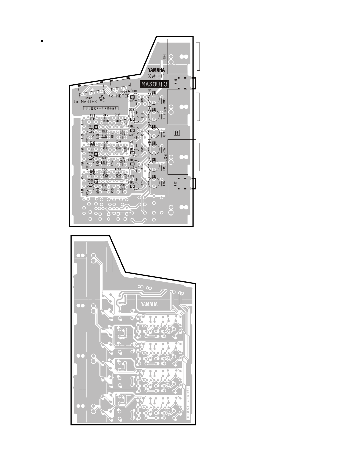
MASOUT3 Circuit Board
to MAS3-CN310 (ST OUT)
to MAS3-CN321 (MON1)
MONITOR OUT (L)
ST OUT (L)
to METER 2-1, 2-2-CN104
MONITOR OUT (MONO/C)
ST OUT (MONO/C)
MONITOR OUT (R)
ST OUT (R)
Component side
36
Pattern side
MASOUT3 : 3NA-V431500
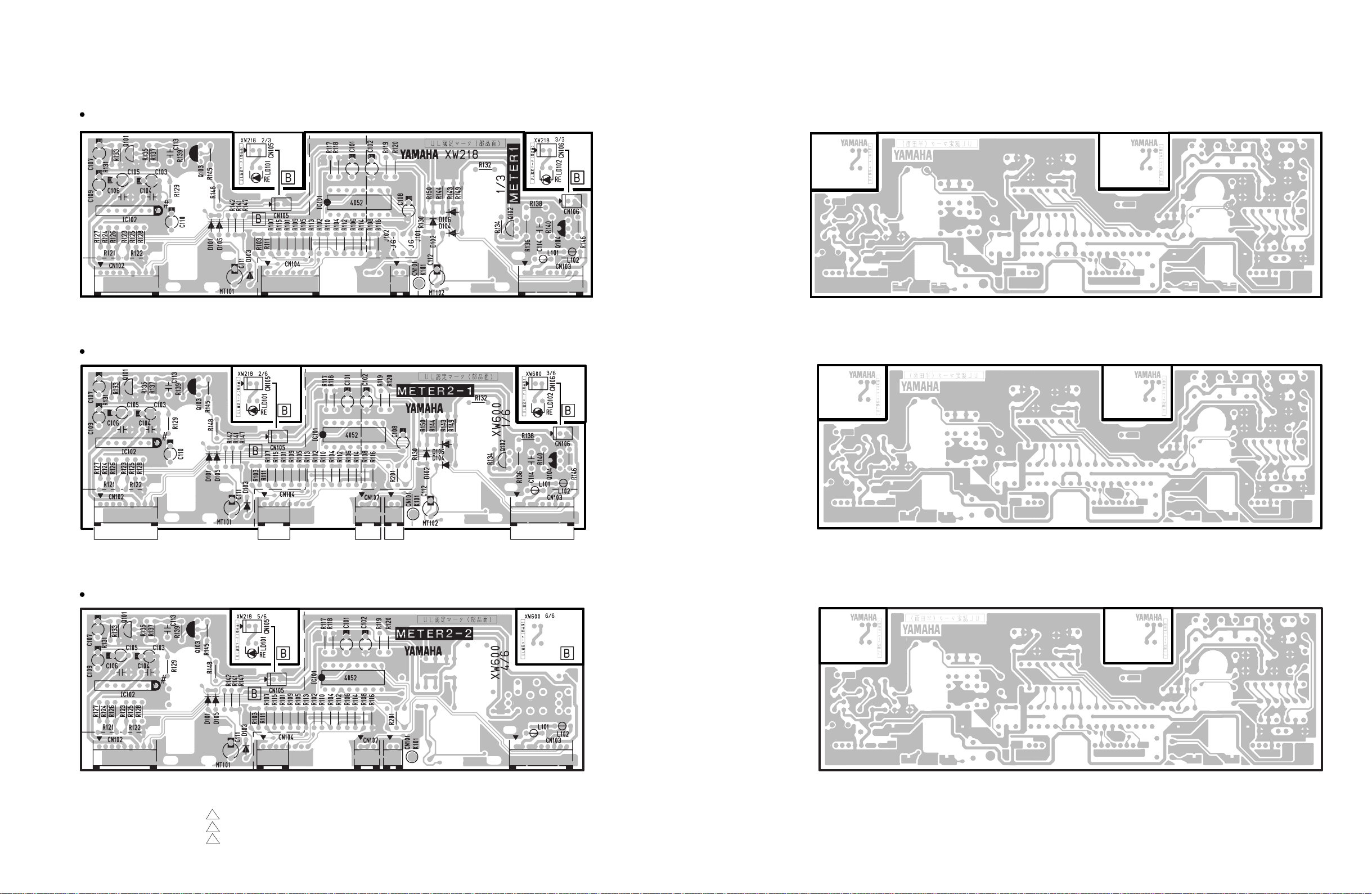
METER1 Circuit Board
M2500
to METER
METER2-1 Circuit Board
to METER
NC
METER2-2 Circuit Board
MASOUT2-CN331
to MASOUT3
-CN331
to GOOSE NECKto MASOUT1
to ISRT
& METER
to GOOSE
NECK
to INSERT
to METER
Component side
Component side
Pattern side
Pattern side
to METER
NC
METER1: 3NA-V431480 2
METER2-1: 3NA-V431490 1
METER2-2: 3NA-V431490 1
to MASOUT3
-CN331
to ISRT
& METER
to GOOSE
& NECK
Component side
Pattern side
37
M2500
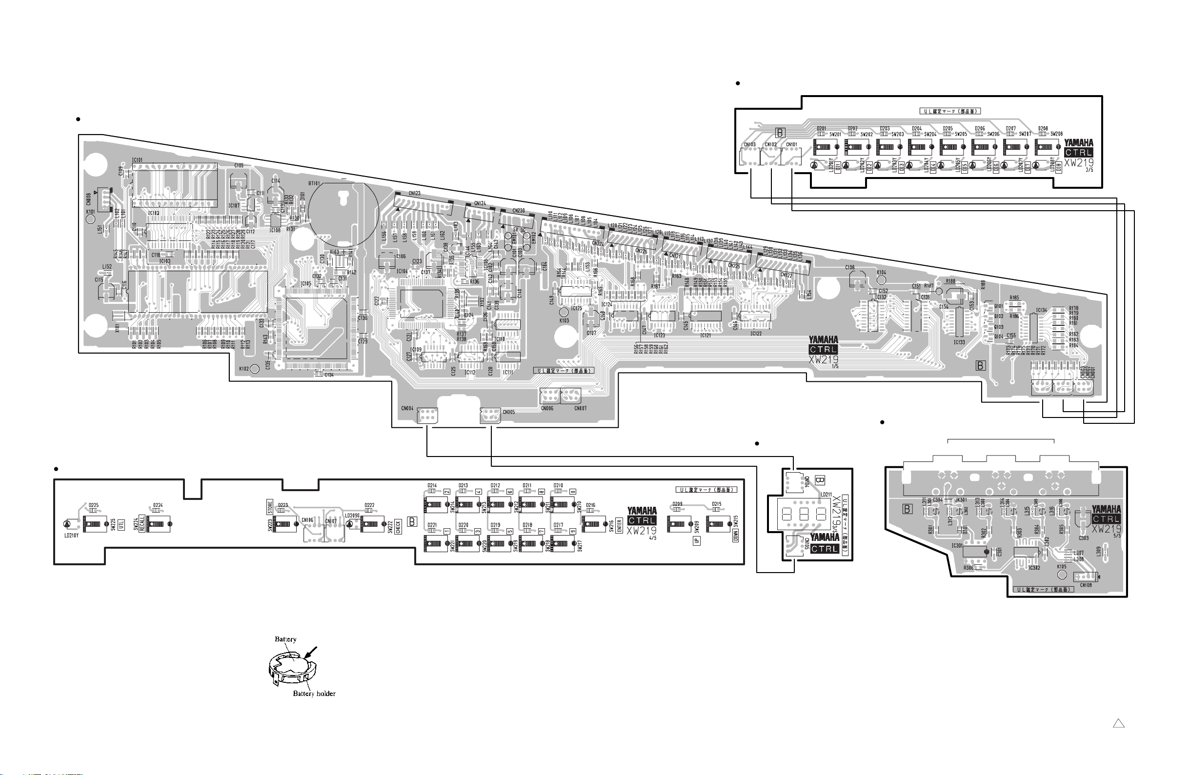
CTRL Circuit Board 1/5
CTRL Circuit Board 2/5
to CTRL5/5
-CN108
to MAS 2
-CN209
to MAS 2
-CN210
to ISRT
-CN409 to ISRT
to CTRL4/5
-CN106
-CN405
to CTRL4/5
-CN107
to ISRT
-CN406
N.C.
to ISRT
-CN404
N.C.
Component side
CTRL Circuit Board 3/5
Component side
CTRL Circuit Board 5/5
IN OUT THRU
MIDI
38
CTRL Circuit Board 4/5
Battery VN103500
VN103600(Battery holder for VN103500)
• Notice for back-up battery removal
Push the battery as shows in figure,
then the battery will pop up.
• Druk de batterij naar beneden zoals
aangeven in de tekening, de batterij
springt dan naar voren.
to CTRL1/5
-CN006
to CTRL1/5
-CN007
Component side
Component side
to CTRL1/5
-CN108
Component side
CTRL: 3NA-V431460 3
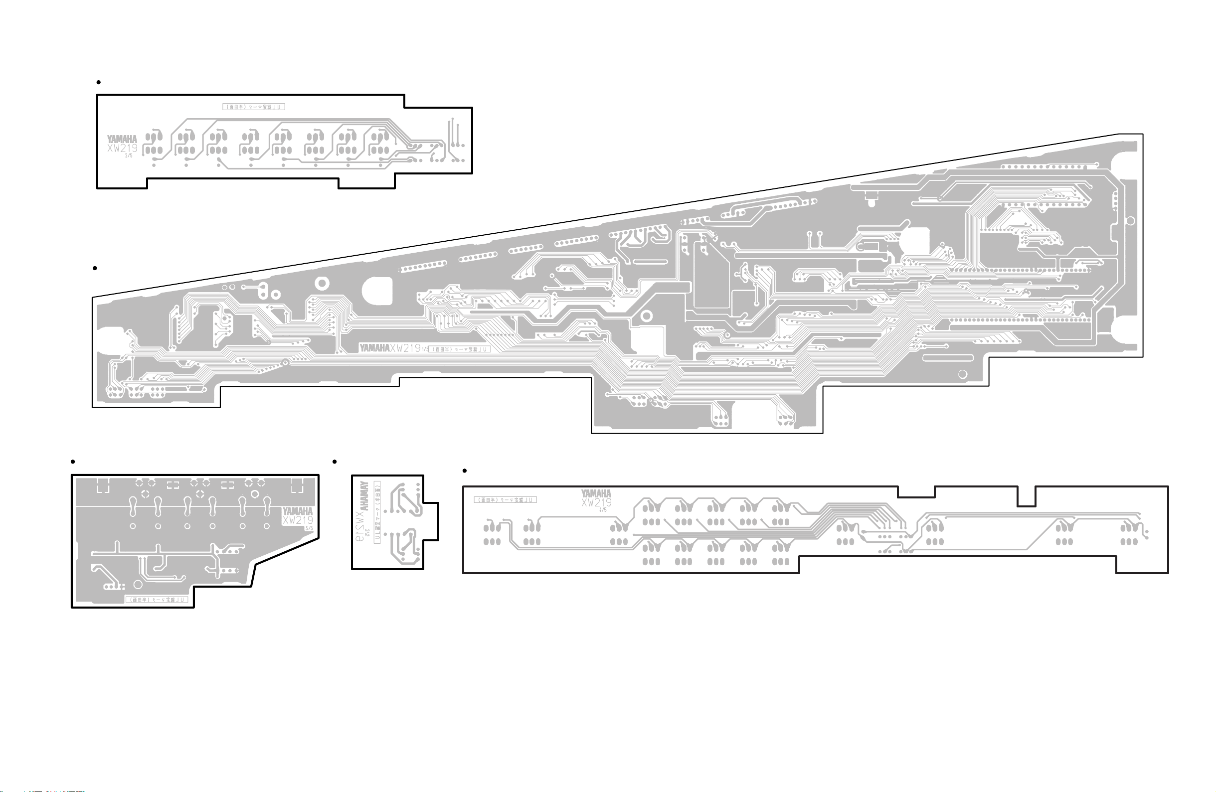
CTRL Circuit Board 2/5
CTRL Circuit Board 1/5
M2500
Pattern side
CTRL Circuit Board 5/5
Pattern side
CTRL Circuit Board 3/5
Pattern side
CTRL Circuit Board 4/5
Pattern side
Pattern side
39
M2500
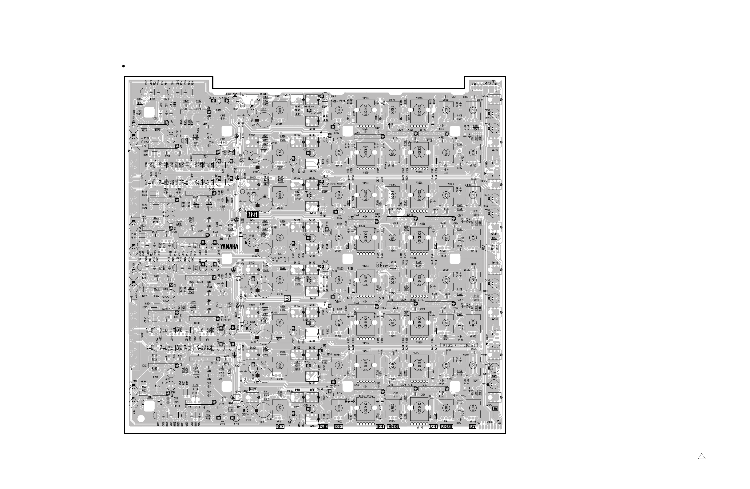
to INJK-CN602
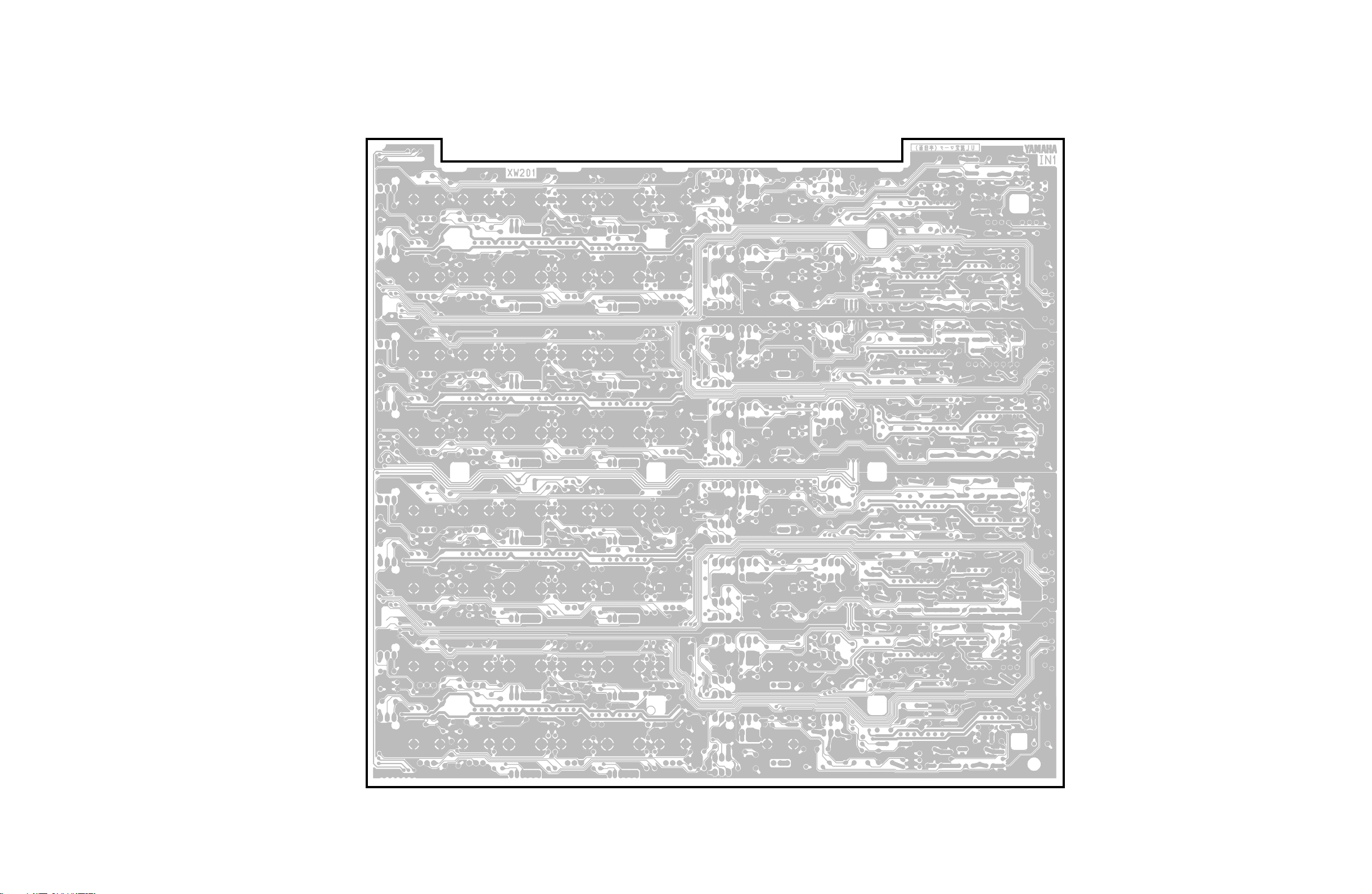
IN1 Circuit Board
to IN1-CN105
ISRT-CN212
NC
to IN2
-CN202
40
to INJK-CN601
to IN2
-CN201
to IN2-CN106
ISRT-CN314
NC
Component side
3NA-V431320 1
M2500
Pattern side
41
M2500
to IN1
-CN104
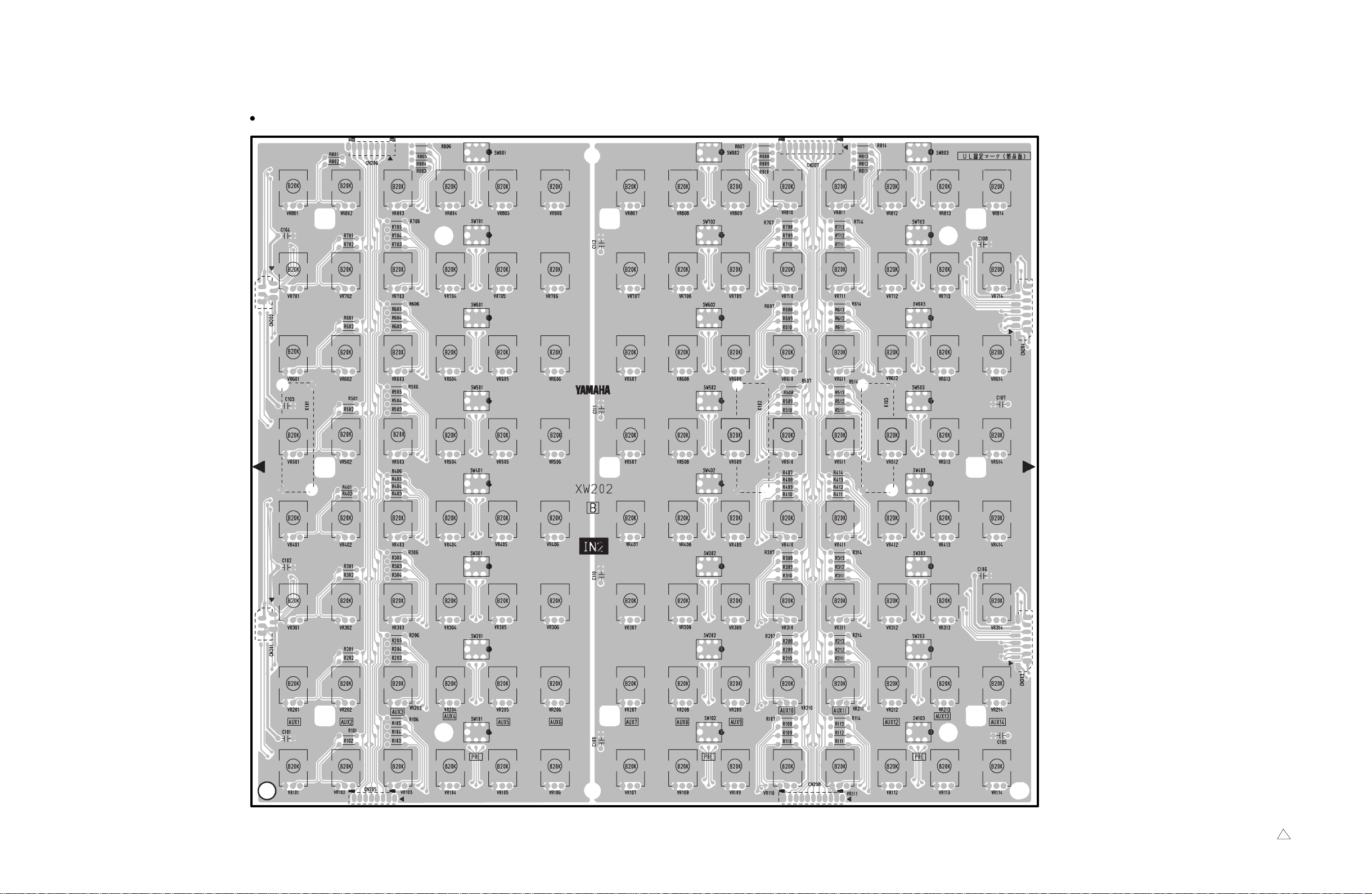
IN2 Circuit Board
to IN2-CN208
ISRT-CN203, 205
NC
to IN3
-CN302
42
to IN1
-CN103
to IN2-CN206
ISRT-CN301
NC
to IN2-CN207
ISRT-CN303, 305
NC
to IN3
-CN301
Component side
3NA-V431330 1
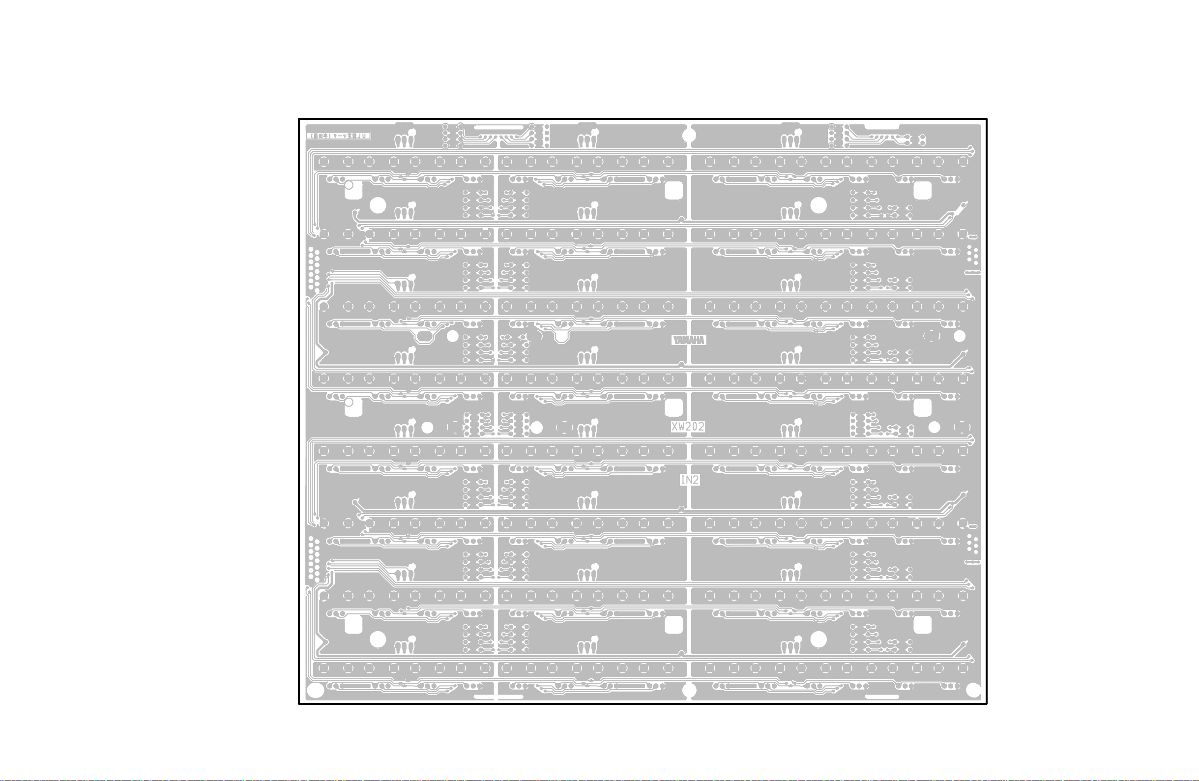
M2500
Pattern side
43
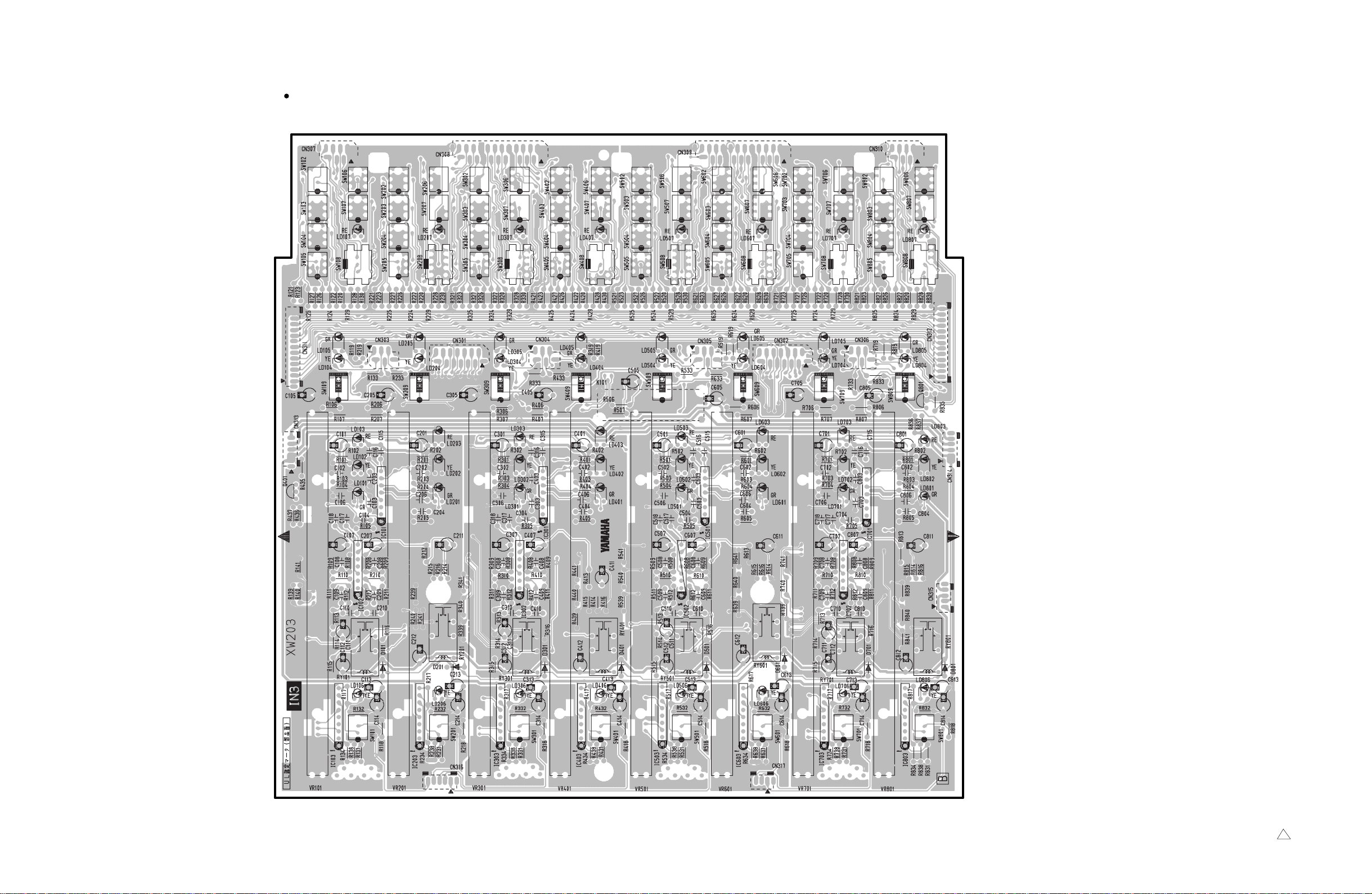
M2500
IN3 Circuit Board
to INPAN-CN501 to INPAN-CN502 to INPAN-CN503 to INPAN-CN504
to IN3-CN312
ISRT-CN306, 308
NC
CN303: to IN4-CN401
CN301: to IN2-CN203
CN304: to IN4-CN402
to IN3-CN314
ISRT-CN313
NC
to IN3-CN311
ISRT-CN206, 208
NC
CN305: to IN4-CN403
CN302: to IN2-CN204
CN306: to IN4-CN404
to IN3-CN313
ISRT-CN213
NC
to IN4-CN405
44
to IN4-CN408 to IN4-CN409
Component side
3NA-V431350 1
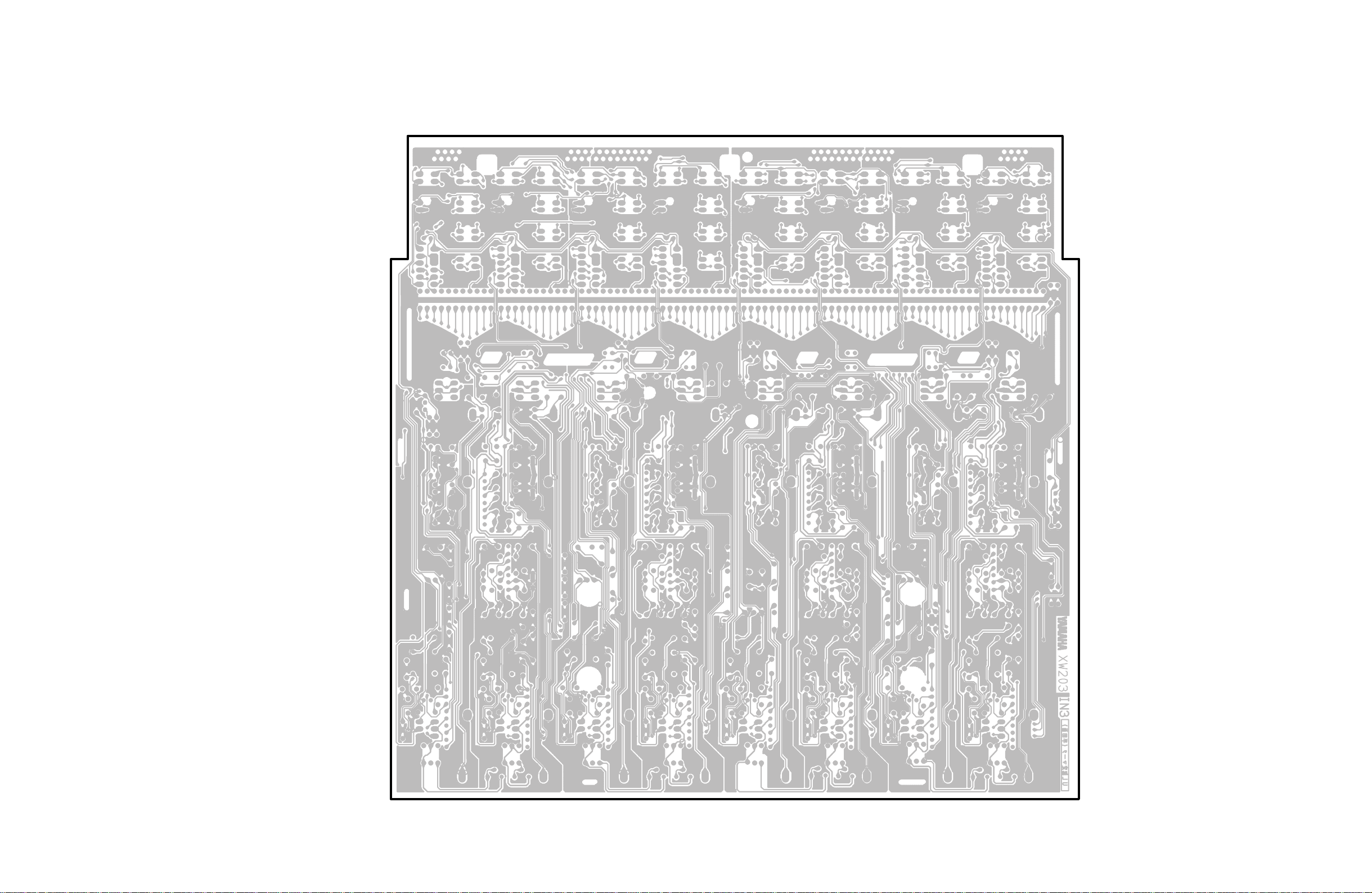
M2500
Pattern side
45
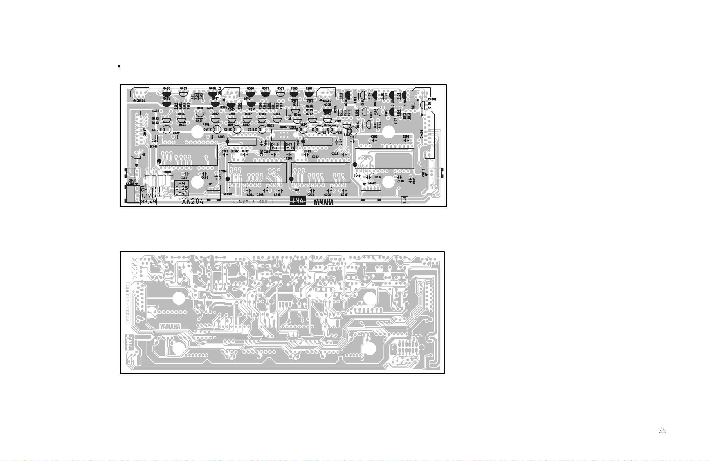
M2500
IN4 Circuit Board
to IN3-CN305 to IN3-CN305 to IN3-CN304 to IN3-CN303
to IN4-CN406
ISRT-CN401
NC
to IN4-CN410
ISRT-CN239
NC
to IN3-CN315
to IN3-CN317
to IN3-CN316
to IN4-CN407
ISRT-CN502
NC
to IN4-CN411
ISRT-CN315
NC
Component side
46
Pattern side
3NA-V431360 1
 Loading...