

YAMAHA 200A, L200A PARTS CATALOGUE

200A
L200A
60H-28197-5E-11
290446
SERVICE MANUAL

NOTICE
This manual has been prepared by Yamaha primarily for use by Yamaha dealers and their trained
mechanics when performing maintenance procedures and repairs to Yamaha equipment. It has
been written to suit the needs of persons who have a basic understanding of the mechanical and
electrical concepts and procedures inherent in the work, for without such knowledge attempted
repairs or service to the equipment could render it unsafe or unfit for use.
Because Yamaha has a policy of continuously improving its products, models may differ in detail
from the descriptions and illustrations given in this publication. Use only the latest edition of this
manual. Authorized Yamaha dealers are notified periodically of modifications and significant
changes in specifications and procedures, and these are incorporated in successive editions of this
manual.
Important information
Particularly important information is distinguished in this manual by the following notations:
⁄ The Safety Alert Symbol means ATTENTION! BECOME ALERT! YOUR SAFETY IS
INVOLVED!
Failure to follow WARNING instructions could result in severe injury or death to the machine
operator, a bystander, or a person inspecting or repairing the outboard motor.
A CAUTION indicates special precautions that must be taken to avoid damage to the outboard
motor.
NOTE:
A NOTE provides key information to make procedures easier or clearer.
200A, L200A
SERVICE MANUAL
©2002 by Yamaha Motor Co., Ltd.
1st Edition, February 2002
All rights reserved.
Any reprinting or unauthorized use
without the written permission of
Yamaha Motor Co., Ltd.
is expressly prohibited.
Printed in Japan
Contents
General information
Specifications
Periodic checks and adjustments
Fuel system
Power unit
GEN
INFO
SPEC
CHK
ADJ
FUEL
POWR
Lower unit
Bracket unit
Electrical systems
Troubleshooting
Index
LOWR
BRKT
–+
ELEC
TRBL
SHTG

GEN
GEN
INFO
INFO
General information
General information
General information
How to use this manual ................................................................................................1-1
Manual format...........................................................................................................1-1
Symbols ....................................................................................................................1-2
Safety while working..................................................................................................... 1-3
Fire prevention..........................................................................................................1-3
Ventilation .................................................................................................................1-3
Self-protection...........................................................................................................1-3
Parts, lubricants, and sealants..................................................................................1-3
Good working practices ............................................................................................1-4
Disassembly and assembly ......................................................................................1-4
Identification ..................................................................................................................1-5
Applicable models.....................................................................................................1-5
Serial number ...........................................................................................................1-5
Features and benefits ...................................................................................................1-6
Hour meter................................................................................................................1-6
Exhaust components (Factory option) ......................................................................1-7
Piston and cylinder ...................................................................................................1-8
Connecting rod .........................................................................................................1-9
Gasket.....................................................................................................................1-10
Reduction gear and clutch ......................................................................................1-11
Power unit mount bolt .............................................................................................1-12
Propeller selection ......................................................................................................1-13
Propeller size ..........................................................................................................1-13
Selection .................................................................................................................1-13
Predelivery checks...................................................................................................... 1-14
Checking the fuel system........................................................................................1-14
Checking the gear oil ..............................................................................................1-14
Checking the battery...............................................................................................1-14
Checking the outboard motor mounting position ....................................................1-14
60H5E11

Checking the remote control cables........................................................................1-15
Checking the steering system.................................................................................1-15
Checking the gearshift and throttle operation .........................................................1-15
Checking the tilt sytem............................................................................................1-15
Checking the engine start switch and engine stop switch, engine shut-off switch.........
Checking the pilot water outlet................................................................................1-16
Test run ...................................................................................................................1-16
Break-in ..................................................................................................................1-17
After test run ...........................................................................................................1-17
1-16
1
60H5E11
GEN
A
1
2
3
4
5
6
7
8
9
10
11
12
13
14
15
INFO
General information
How to use this manual
Manual format
The format of this manual has been designed to make service procedures clear and easy to understand. Use the information below as a guide for effective and quality service.
1 Parts are shown and detailed in an exploded diagram and are listed in the components list.
2 Tightening torque specifications are provided in the exploded diagrams and after a numbered step
with tightening instructions.
3 Symbols are used to indicate important aspects of a procedure, such as the grade of lubricant and
lubrication point.
4 The components list consist of parts and part quantities, as well as bolt, screw, O-ring, and hose
dimensions.
5 Service points regarding removal, checking, and installation are shown in individual illustrations to
explain the relevant procedure.
NOTE:
For troubleshooting procedures, see Chapter 9, “Troubleshooting.”
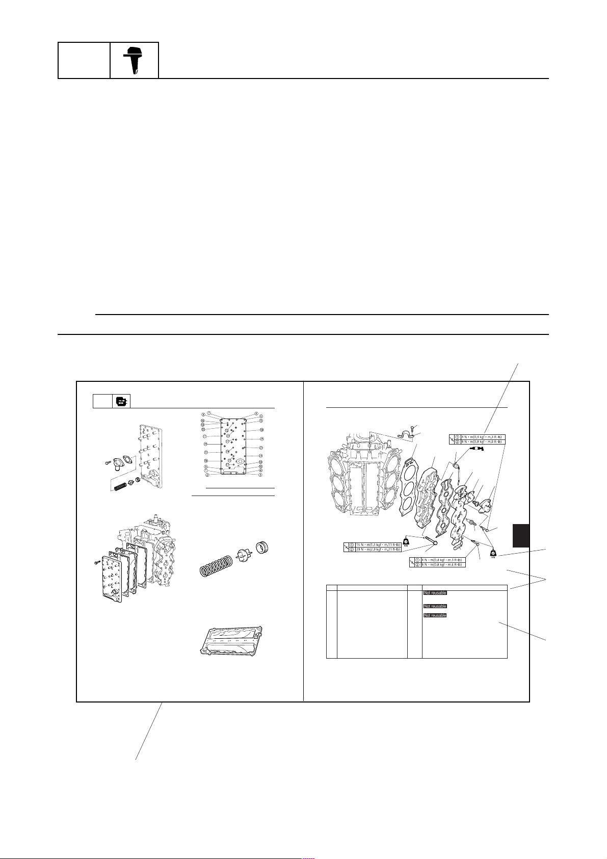
POWR
Removing the exhaust cover
1. Remove the pressure control valve.
2. Remove the exhaust outer cover, and the
exhaust inner cover.
Power unit
60H50250
60H50260
NOTE:
Loosen the bolts in the sequence shown.
3. Remove the cylinder block exhaust inner
cover.
4. Check the pressure control valve for cracks
or damage. Also check the pressure control valve seat for deformation. Replace
them if necessary.
5. Check the spring for fatigue or deformation. Replace it if necessary.
6. Check the exhaust cover for distortion or
corrosion. Replace it if necessary.
60H50265
60H50270
60H50275
Cylinder head
No. Part name Q’ty Remarks
1 Gasket 2
2 Cylinder head 2
3 Thermo switch 2
4 Gasket 2
5 Cylinder head cover 2
6 Gasket 2
7 Thermostat 2
8 Thermostat cover 2
9 Bolt 8 M6 x 40 mm
10 Bolt 36 M6 x 30 mm
11 Bolt 24 M8 x 60 mm
12 Clamp 1
13 Bolt 2 M8 x 20 mm
14 Engine hanger 1
15 Spark plug 6
Exhaust / Cylinder head
60H50280
2
5
3
1
4
5-21
1-1
5
60H5E11
60H5E11
5-22
60H5E11
How to use this manual
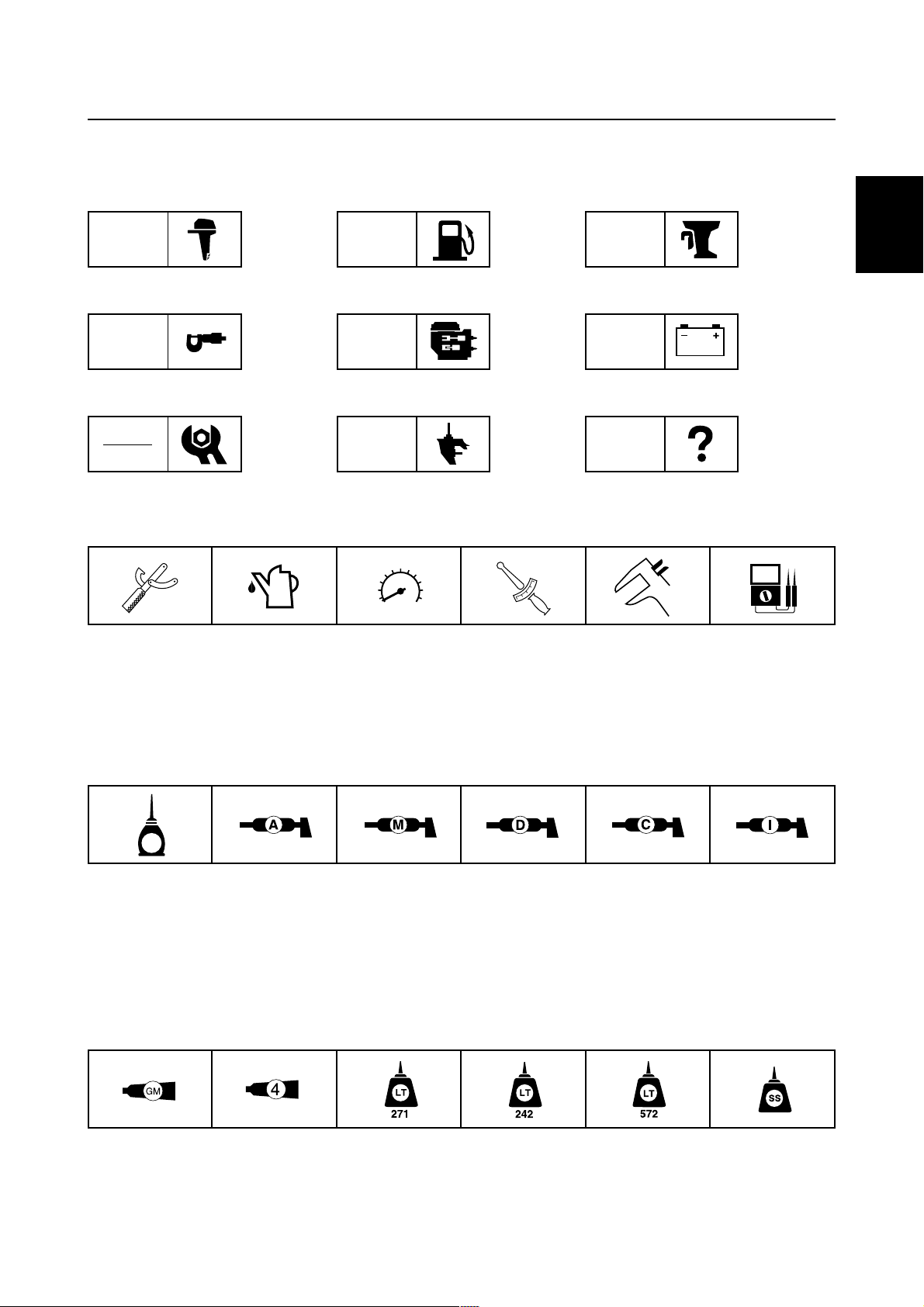
Symbols
The symbols below are designed to indicate the content of a chapter.
General information Fuel system Bracket unit
GEN
INFO
Specifications Power unit Electrical systems
SPEC
Periodic checks and adjustments Lower unit Troubleshooting
CHK
ADJ
Symbols 1 to 6 indicate specific data.
123456
1 Special tool
2 Specified oil or fluid
3 Specified engine speed
FUEL
POWR
LOWR
BRKT
ELEC
TRBL
SHTG
T
.
R
.
4 Specified tightening torque
5 Specified measurement
6 Specified electrical value
(Resistance, Voltage, Electric current)
1
Symbols 7 to B in an exploded diagram indicate the grade of lubricant and the lubrication point.
7890AB
E
7 Apply Yamaha 4-stroke motor oil
8 Apply water resistant grease (Yamaha grease A)
9 Apply molybdenum disulfide grease
0 Apply corrosion resistant grease
(Yamaha grease D)
Symbols C to H in an exploded diagram indicate the type of sealant or locking agent and the application point.
CDEFGH
C Apply Gasket Maker
D Apply Yamabond 4
E Apply LOCTITE 271 (Red)
A Apply low temperature resistant grease
(Yamaha grease C)
B Apply injector grease
F Apply LOCTITE 242 (Blue)
G Apply LOCTITE 572
H Apply silicon sealant
60H5E11
1-2
GEN
INFO
General information
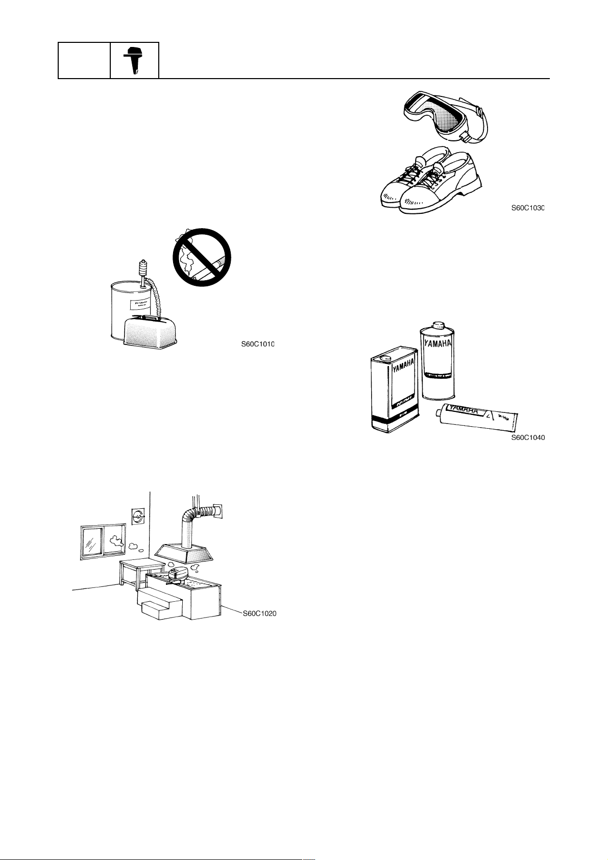
Safety while working
To prevent an accident or injury and to ensure
quality service, follow the safety procedures
provided below.
Fire prevention
Gasoline is highly flammable.
Keep gasoline and all flammable products
away from heat, sparks, and open flames.
Parts, lubricants, and sealants
Use only genuine Yamaha parts, lubricants,
and sealants or those recommended by
Yamaha, when servicing or repairing the
outboard motor.
Ventilation
Gasoline vapor and exhaust gas are heavier
than air and extremely poisonous. If inhaled
in large quantities they may cause loss of
consciousness and death within a short time.
When test running an engine indoors (e.g., in
a water tank) be sure to do so where adequate
ventilation can be maintained.
Self-protection
Protect your eyes by wearing safety glasses
or safety goggles during all operations involving drilling and grinding, or when using an air
compressor.
Protect your hands and feet by wearing protective gloves and safety shoes when necessary.
Under normal conditions, the lubricants mentioned in this manual should not harm or be
hazardous to your skin. However, you should
follow these precautions to minimize any risk
when working with lubricants.
1. Maintain good standards of personal and
industrial hygiene.
2. Change and wash clothing as soon as possible if soiled with lubricants.
3. Avoid contact with skin. Do not, for example, place a soiled rag in your pocket.
4. Wash hands and any other part of the body
thoroughly with soap and hot water after
contact with a lubricant or lubricant soiled
clothing has been made.
5. To protect your skin, apply a protective
cream to your hands before working on the
outboard motor.
1-3
60H5E11
Safety while working
6. Keep a supply of clean, lint-free cloths for
wiping up spills, etc.
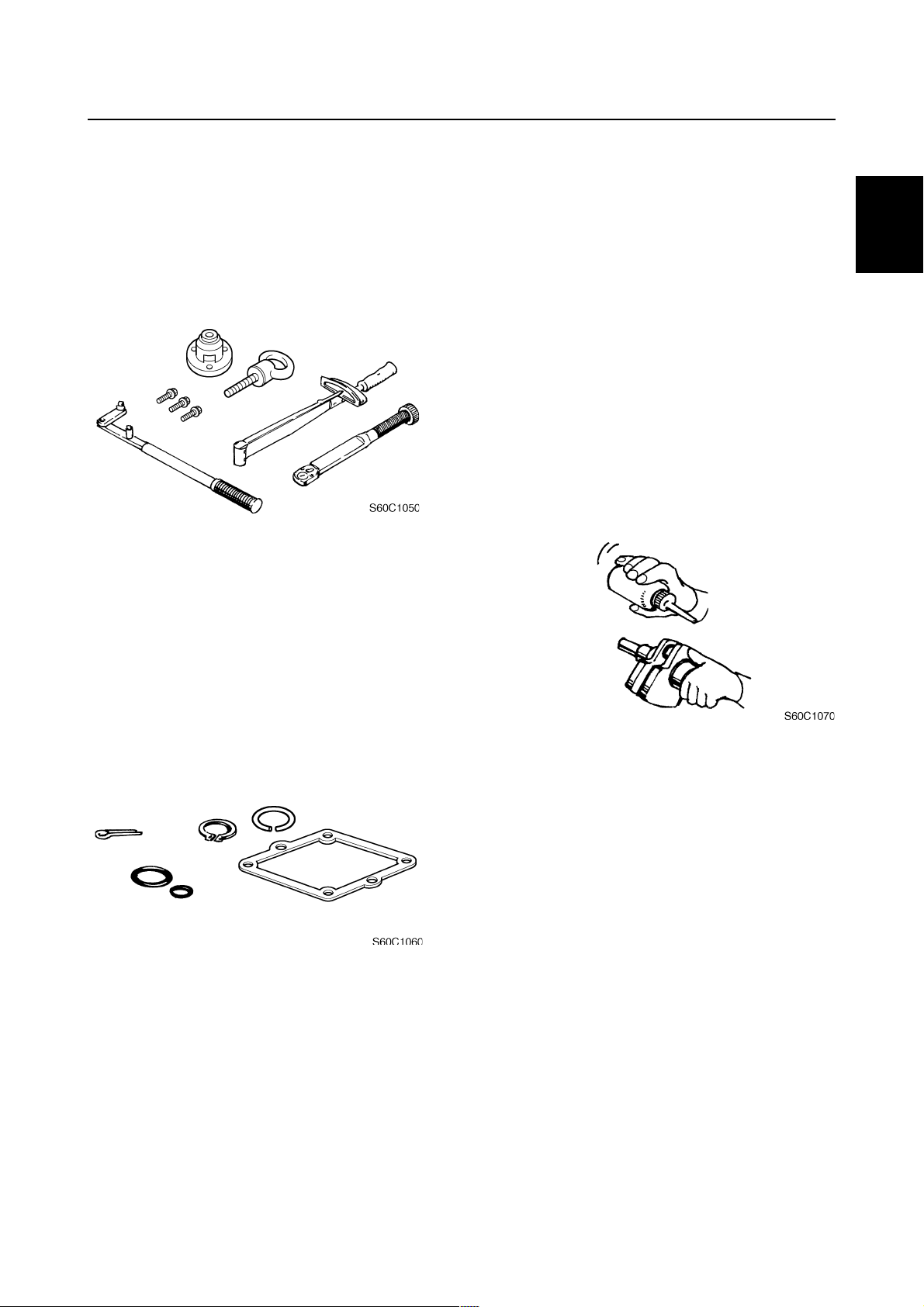
Good working practices
Special tools
Use the recommended special tools to protect
parts from damage. Use the right tool in
the right manner-do not improvise.
Tightening torques
Follow the tightening torque specifications
provided throughout the manual. When tightening nuts, bolts, and screws, tighten the
large sizes first, and tighten fasteners starting
in the center and moving outward.
Disassembly and assembly
1. Use compressed air to remove dust and
dirt during disassembly.
2. Apply engine oil to the contact surfaces of
moving parts before assembly.
3. Install bearings with the manufacture identification mark in the direction indicated in
the installation procedure. In addition, be
sure to lubricate the bearings liberally.
4. Apply a thin coat of water-resistant grease
to the lip and periphery of an oil seal before installation.
5. Check that moving parts operate normally
after assembly.
1
Non-reusable parts
Always use new gaskets, seals, O-rings, cotter pins, circlips, etc., when installing or
assembling parts.
60H5E11
1-4
GEN
INFO
General information
Identification
Applicable models
This manual covers the following models.
Applicable models
200AET,L200AET
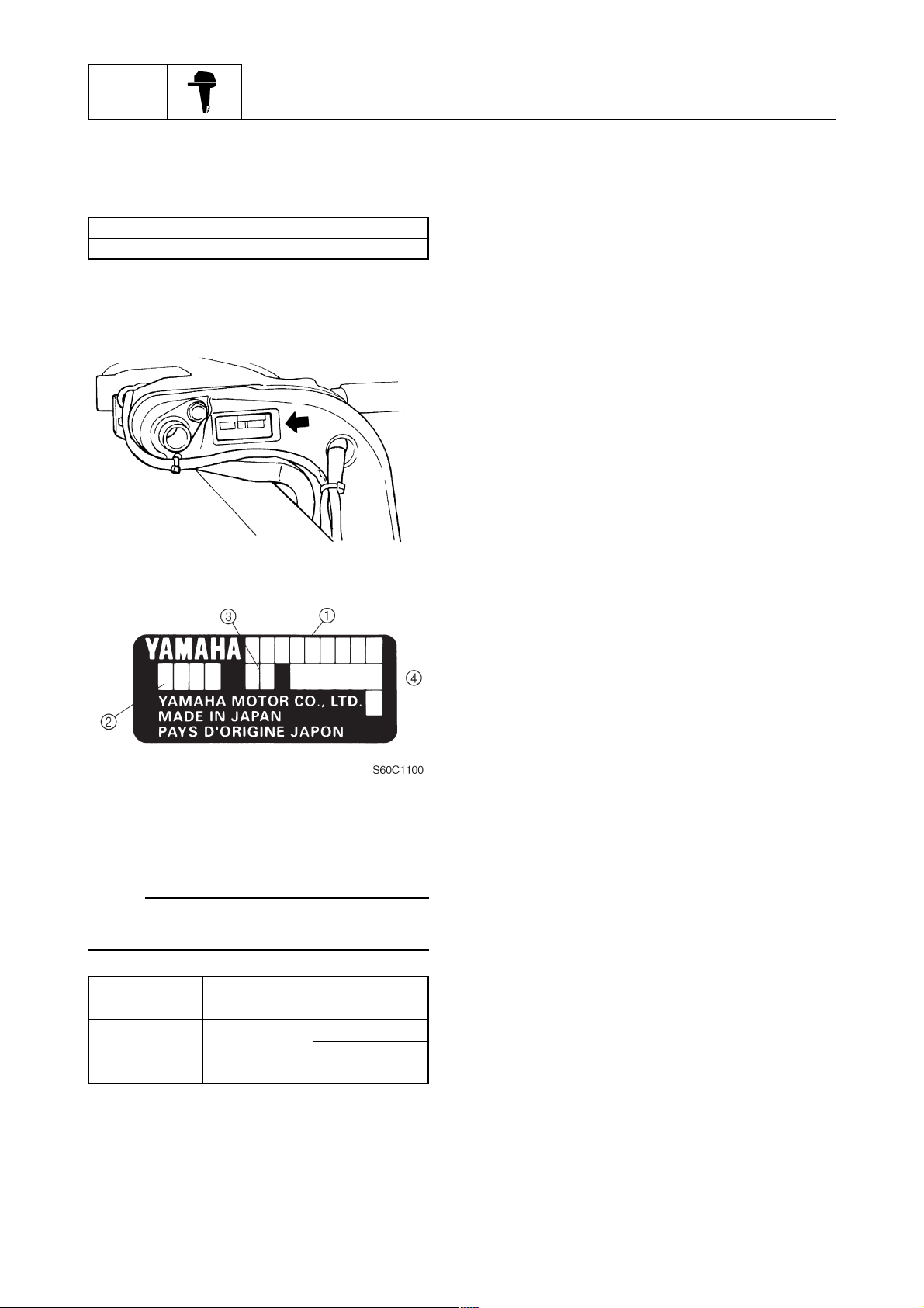
Serial number
The outboard motor serial number is stamped
on a label attached to the port clamp bracket.
60H10000
1 Model name
2 Approved model code
3 Transom height
4 Serial number
NOTE:
If the serial number label is removed, VOID
marks will appear on the label.
Model name
200AET
L200AET
Approved
model code
60H
60J
Starting
serial No.
L: 800101X: 850101X: 800101-
1-5
60H5E11
Identification / Features and benefits
Features and benefits
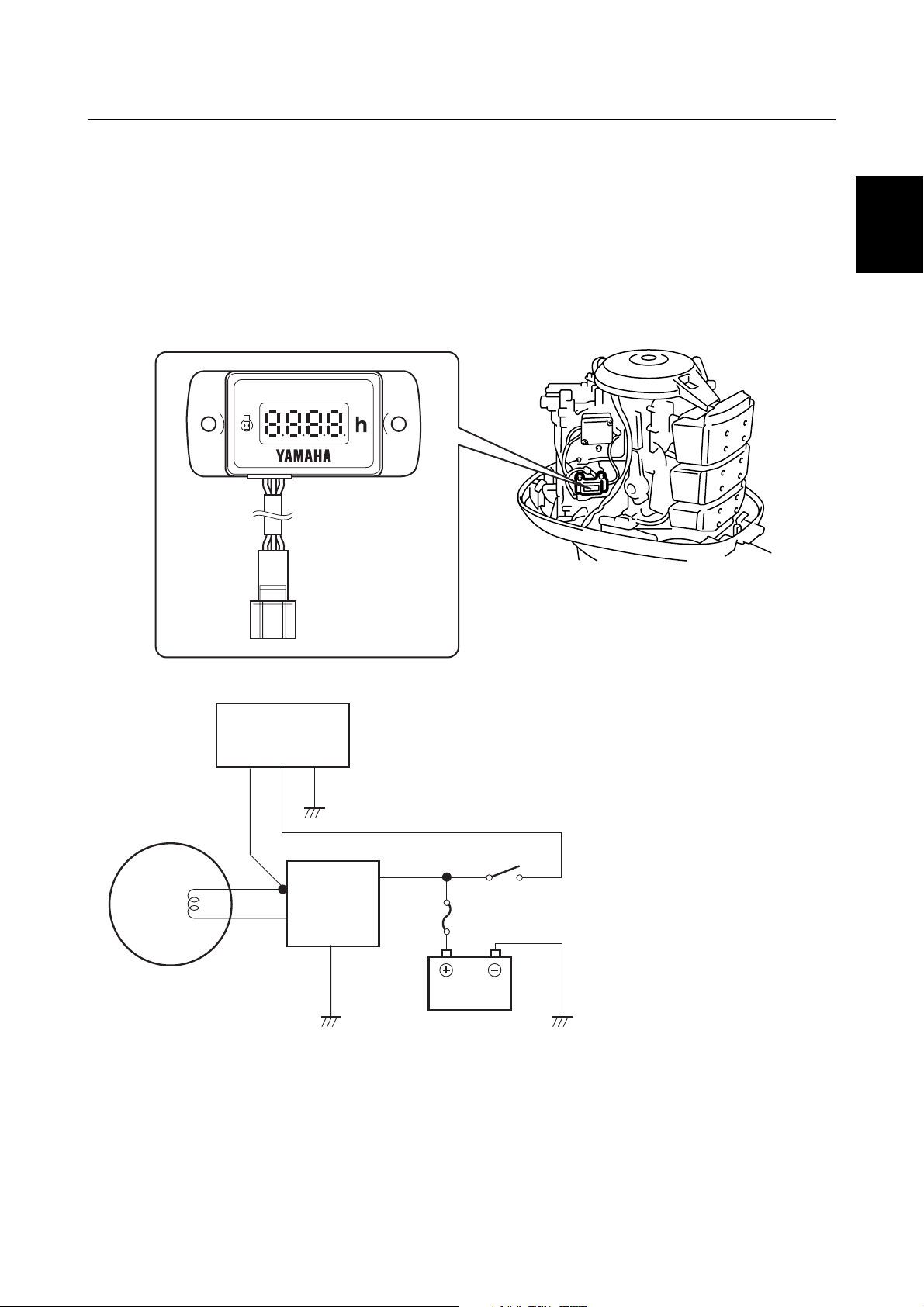
Hour meter
A hour meter is incorporated for easier control of interval time for the periodic maintenance.
As the main switch is turned on, all segments light up for 2 seconds to check that the Light Emitting
Diode is not failed.
Then, the meter indicates the total of hours which the engine has been run since manufacture.
The indicated hour is the accumulated time detected by the pulse signal from the lighting coil.
The accumulated hour is held forever, and cannot reset.
1
Pulse
(G/W)
Lighting
coil
Flywheel magnet
Hour meter
Hour meter
Rectifier
Regulator
(G)
(B)
Wiring diagram
Grand (B)
Power source (Y)
(R)
Fuse
Battery
Main
switch
(B)
G/W
: Green/White
G
: Green
Y
: Yellow
B
: Black
R
: Red
60H5E11
60H10010
1-6
GEN
INFO
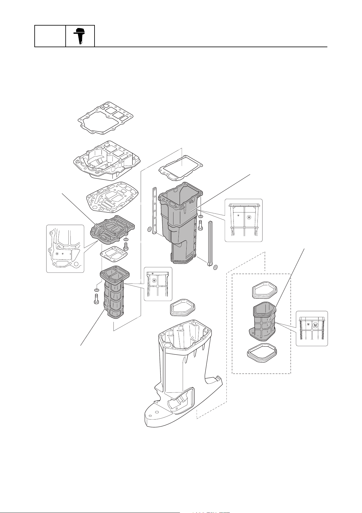
Exhaust components (Factory option)
The cylindrical components have been painted externally and internally after the anodic oxide coating
to make a film for additional corrosion-resistance.
Exhaust
guide plate
General information
Muffler
Exhaust manifold
Exhaust
manifold
extension
(Muffler 2)
For X transom
1-7
60H10030
60H5E11
Features and benefits
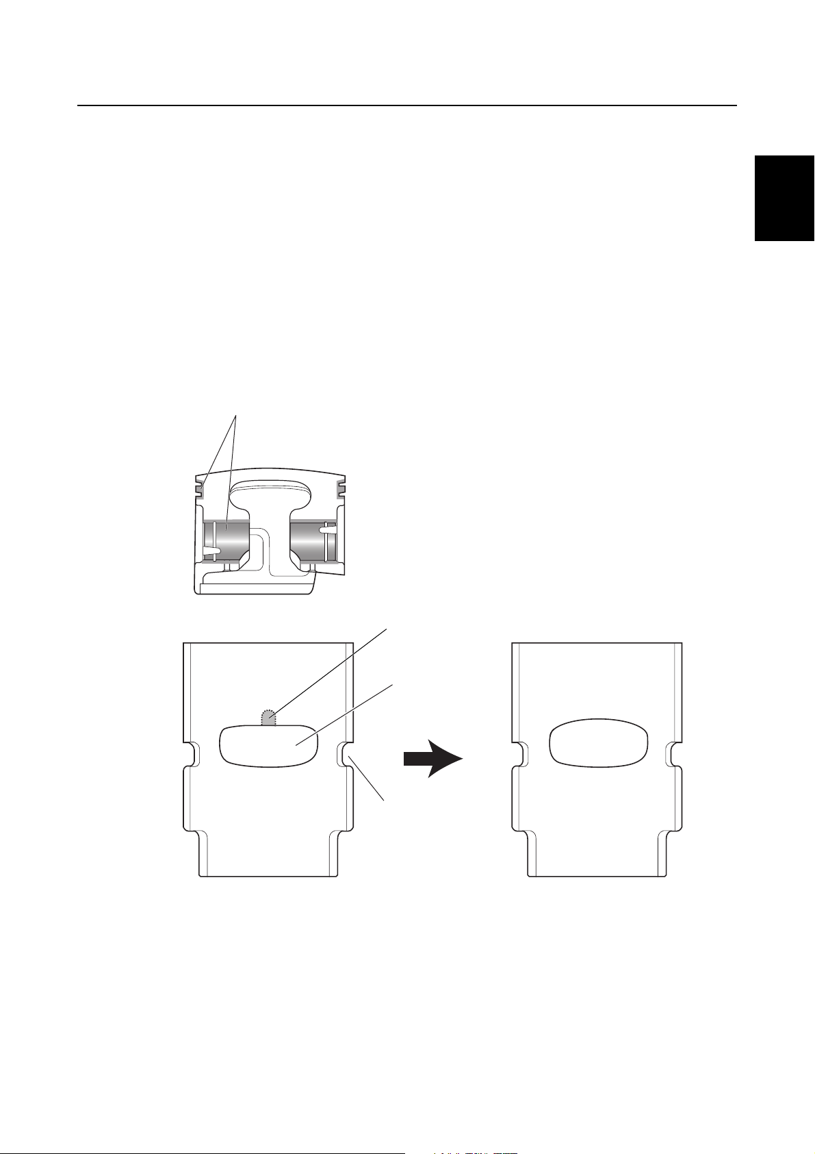
Piston and cylinder
Following items have been given to improve the durability for the piston and cylinder.
A hard anodic oxide coating has been given to the piston pin boss and piston ring groove of the #1
and #2 piston.
Multilayer plating has been given to the piston ring.
The cylinder sleeve without the exhaust slit has been adopted not to accumulate some deposits,
which can prevent the piston rings from entwining.
Also, the shape of the exhaust port has been given the gradual curve design to obtain the best engine
performance and avoid scuffing of the piston ring.
Hard anodic oxide coating
1
Piston
Cylinder sleeve
Exhaust slit
Exhaust port
Scavenging port
Cylinder sleeve
(New models)(Previous models)
60H5E11
60H10040
1-8
GEN
INFO
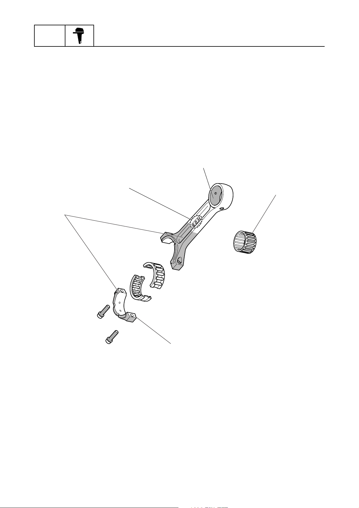
Connecting rod
A process of the carburizing and quenching has been given to the inside of the small end to increase
the strength.
The small end bearing has been given 18 rollers, adding one roller from the previous model, to
increase the durability.
The mating face of the big end bearing has been given a large area to increase the rigidity after
assembling the bearing cap, which increases the rigidty.
Also, a silver plating (30-40µ) has been given to the outside portion of the big end to increase the less
friction.
General information
Carburizing and quenching
Silver plating
Identification mark
Bearing with 18 rollers
Larger mating face
1-9
Connecting rod and bearings
60H10050
60H5E11
Features and benefits
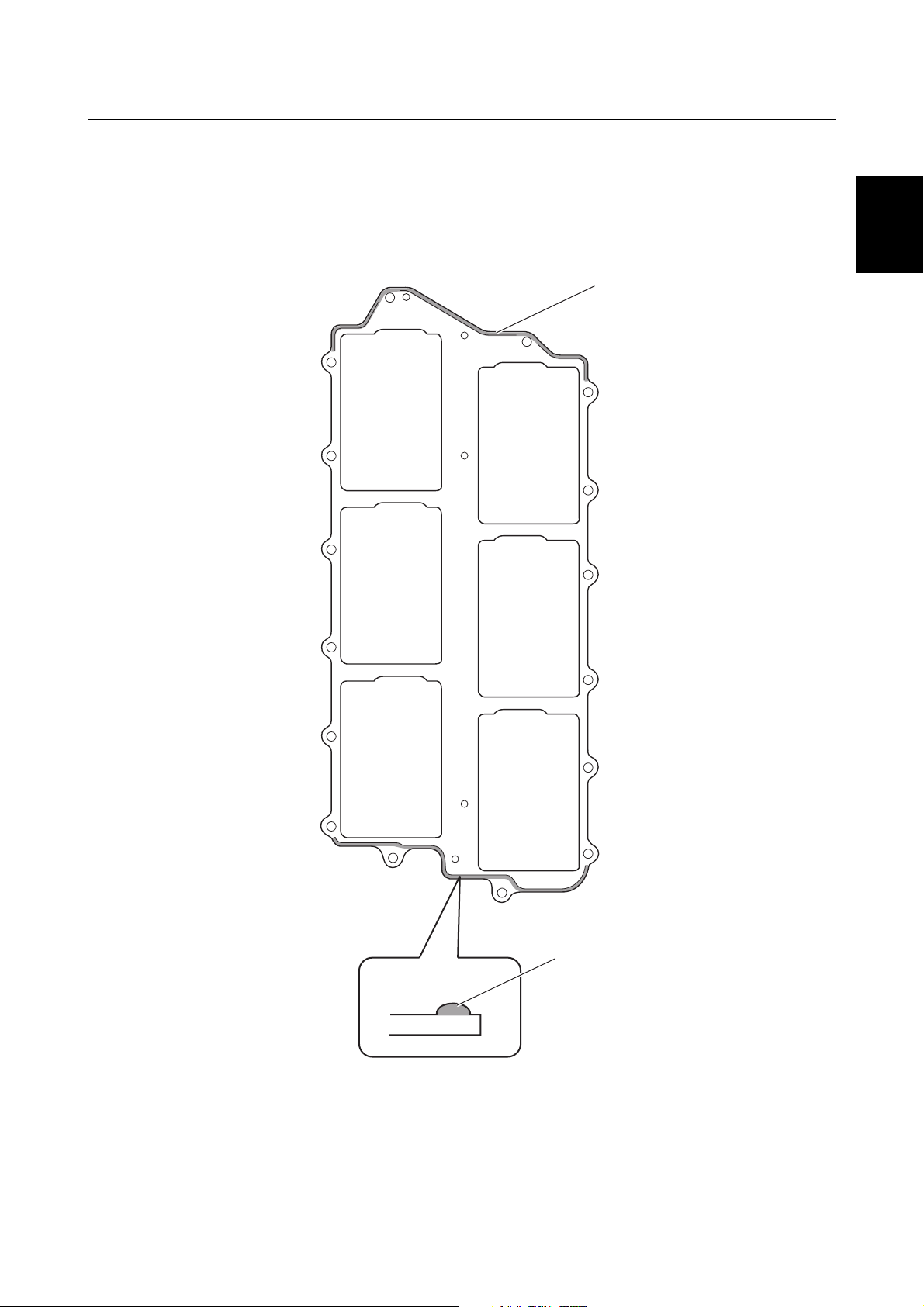
Gasket
The intake manifold gasket has been given a silicon bead to increase more sealer.
Silicon bead
1
60H5E11
Silicon bead
Gasket with silicon bead
60H10060
1-10
GEN
INFO
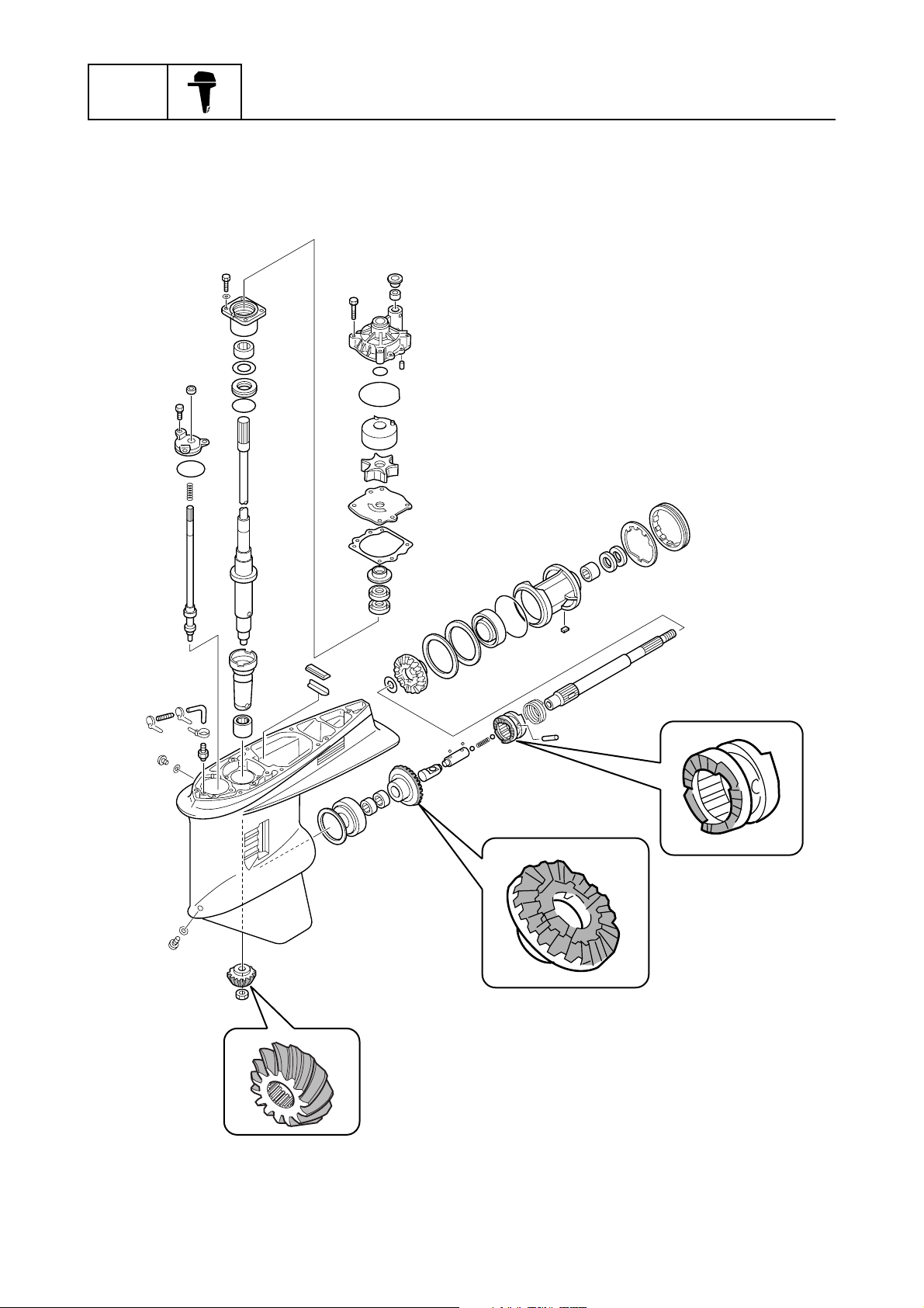
Reduction gear and clutch
The process of the double shot-peening has been given to the surface of the teeth portion of the
pinion gear, forward gear and dog clutch to increase the durability.
General information
1-11
Dog clutch
Forward gear
Pinion gear
60H10070
60H5E11
Features and benefits
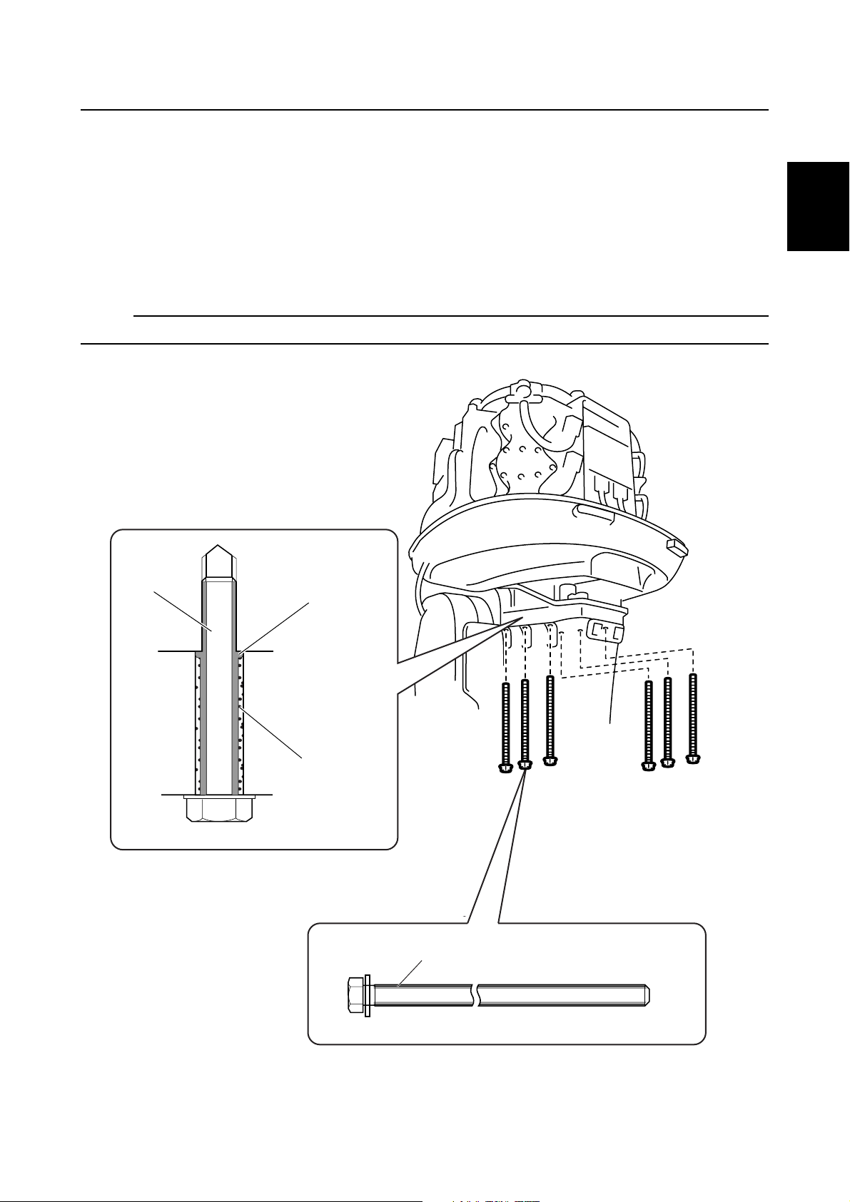
Power unit mount bolt
A fully threaded bolt coated with a sealing material to the thread portion has been adopted for mounting the power unit.
This gives a sealing function to the bolt, which will help prevent the bolt from sticking by the salt water
entering into the thread hole and crystallizing .
Also, the bolt can come out by turning, due to the full thread structure and the sealing material having
a function as an insulator, even if the bolt hole has been choked with corroded particles.
Therefore, an easier servicing such as removing the power unit can be obtained.
NOTE:
Apply a sealing material such as LOCTITE 572 to the bolt thread if the bolt is reused.
1
Bolt
Sealing material
Corroded particles
Bolt hole
Coating with a sealing material
60H5E11
Full threaded bolt
60H10080
1-12
GEN
INFO
General information
Propeller selection
The performance of a boat and outboard motor will be critically affected by the size and type
of propeller you choose. Propellers greatly affect boat speed, acceleration, engine life, fuel
economy, and even boating and steering capabilities. An incorrect choice could adversely
affect performance and could also seriously
damage the engine.
Use the following information as a guide for
selecting a propeller that meets the operating
conditions of the boat and the outboard motor.
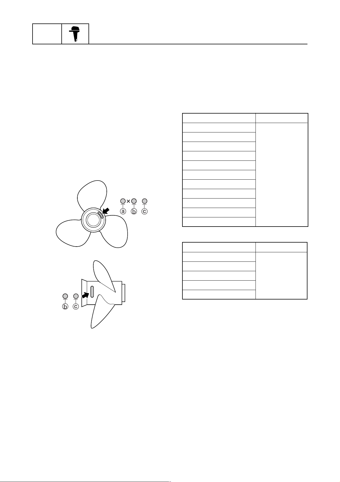
Propeller size
The size of the propeller is indicated on the
propeller blade or outside of the propeller boss.
-
Selection
When the engine speed is at the full throttle
operating range (4,500 – 5,500 r/min), the ideal
propeller for the boat is one that provides maximum performance in relation to boat speed and
fuel consumption.
Regular rotation model
Propeller size (in) Material
13 1/2 x 23-M
13 3/8 x 23-M
13 3/8 x 25-M
13 3/4 x 17-M
13 3/4 x 19-M2
13 3/4 x 21-M Stainless steel
14 x 19-M
14 1/2 x 17-M
14 5/8 x 16-M
15 1/4 x 15-M
15 3/4 x 13-M
-
A Propeller diameter (in inches)
B Propeller pitch (in inches)
C Propeller type (propeller mark)
S60C1110
S60C1125
Counter rotation model
Propeller size (in) Material
13 3/4 x 17-ML
13 3/4 x 19-ML
13 3/4 x 21-ML Stainless steel
13 3/8 x 23-ML
14 1/2 x 17-ML
1-13
60H5E11
Features and benefits / Propeller selection
Predelivery checks
To make the delivery process smooth and efficient, the predelivery checks should be completed as explained below.
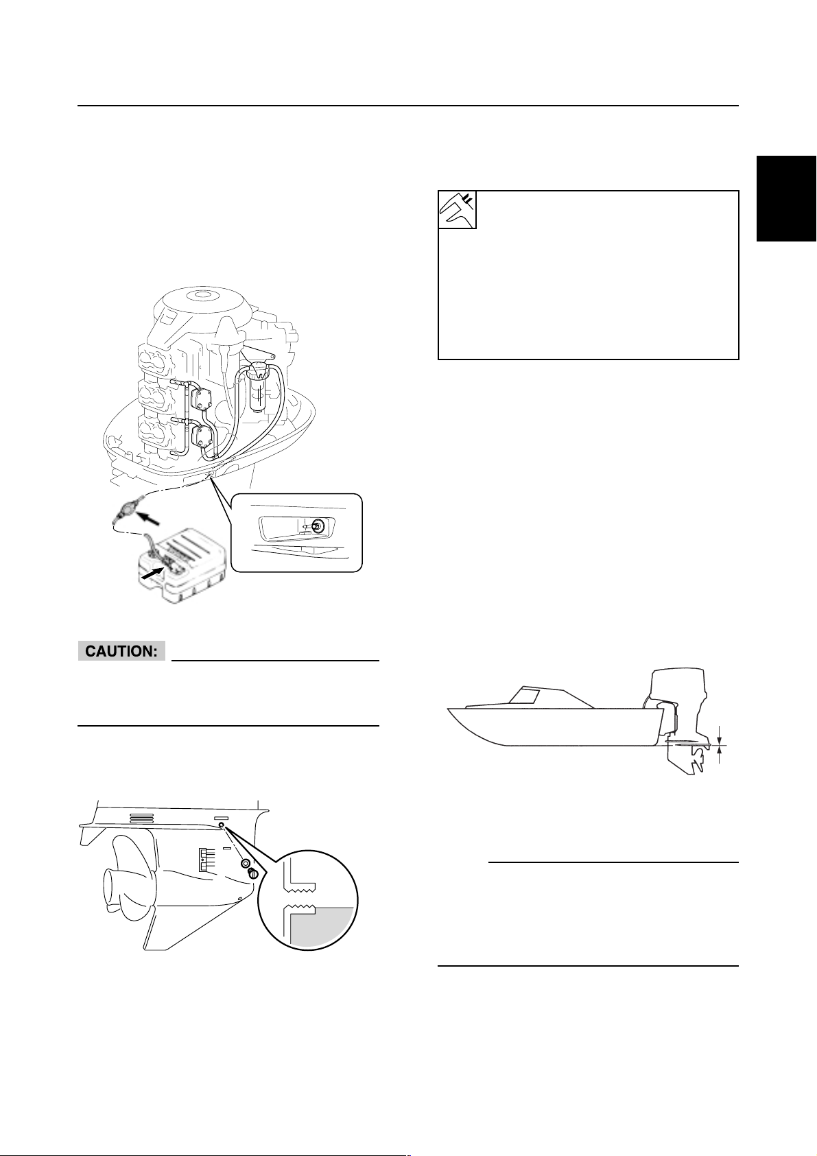
Checking the fuel system
1. Check that the fuel hoses are securely connected and that the fuel tank is full with fuel.
60H00000
Checking the battery
1. Check the capacity, electrolyte level, and
specified gravity of the battery.
Recommend battery:
CCA / SAE (Minimum) : 380 (A)
CCA / EN (Minimum) : 430 (A)
RC (Minimum) : 124 (Minute)
20HR (Minimum) : 70 (AH)
JIS: 65D31-95E41
Electrolyte specified gravity:
1.280 at 20°C (68°F)
2. Check that the red and black battery cables
are securely connected.
Checking the outboard motor mounting position
1. Check that the anti-cavitation plate is
aligned with the bottom of the boat. If the
mounting height is too high, cavitation will
occur and propulsion will be reduced.
Also, the engine speed will increase abnormally and cause the engine to overheat. If
the mounting height is too low, water resistance will increase and reduce engine efficiency.
1
Use pre-mixed fuel only.
Fuel and oil mixing ratio is 50:1. For breakin period, 25:1 mixture shall be used.
Checking the gear oil
1. Check the gear oil level.
60H30450
S60C1160
NOTE:
The optimum mounting height is affected by
the combination of the boat and the outboard
motor. To determine the optimum mounting
height, test run the outboard motor at different
heights.
2. Check that the clamp brackets are secured
with the mounting bolts.
60H5E11
1-14
GEN
INFO
General information
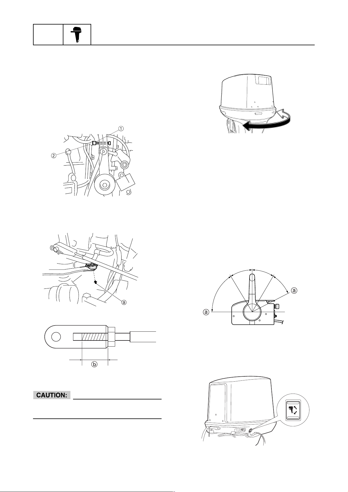
Checking the remote control cables
1. Set the remote control lever to the neutral
position and fully close the throttle lever.
2. Check that the basic ignition timing adjusting screw 1 on the magnet control lever is
in contact with the stopper 2 on the crankcase when the throttle lever is in the fully
closed position.
60H30110
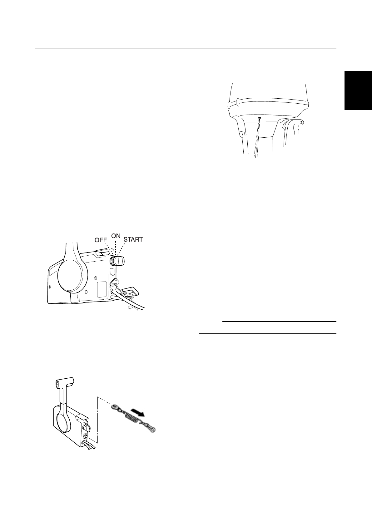
3. Check that the set pin on the shift rod is
aligned with the arrow mark A on the bottom cowling .
Checking the steering system
1. Check that the steering operates smoothly.
60H10090
2. Check that there is no interference with
wires, hoses, or remote control cable when
the outboard motor is steered.
Checking the gearshift and throttle
operation
1. Check that the gearshift operates smoothly
when the remote control lever is shifted from
neutral into forward or reverse.
2. Check that the throttle operates smoothly
when the remote control lever is shifted from
the fully closed position to the fully open
position A.
N
F
R
60H30427
60H10420
The shift/throttle cable joint must be screwed
in a minimum of 8.0 mm (0.31 in)
B.B.
B.
B.B.
1-15
S60C1210
Checking the tilt system
1. Check that the outboard motor tilts up and
down smoothly when operating the power
trim and tilt unit.
60H10095
60H5E11
Predelivery checks
2. Check that there is no abnormal noise produced when the outboard motor is tilted up
or down.
3. Check that there is no interference with
wires, hoses, or remote control cable when
the tilted-up outboard motor is steered.
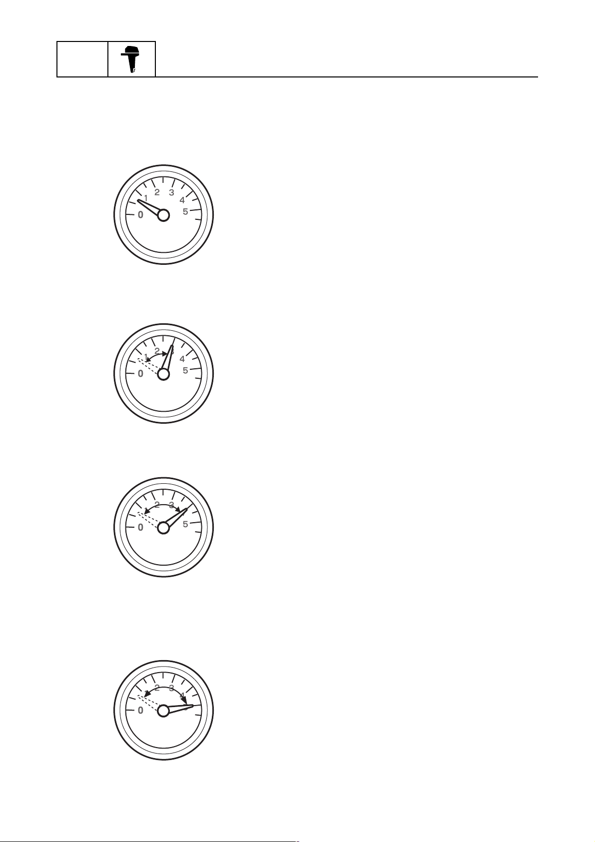
4. Check that the trim meter points down when
the outboard motor is trimmed all the way
down.
Also check that the trim meter moves toward up position when the outboard motor
is trimmed up.
Checking the engine start switch and
engine stop switch, engine shut-off
switch
1. Check that the engine starts when the engine start switch is turned to START.
Checking the pilot water outlet
1. Start the engine, and check that cooling water is discharged from the pilot water outlet.
1
60H30100
Test run
1. Start the engine, and then check the engine idle speed after the engine has been
warmed up.
2. Check that the gearshift operates smoothly.
3. Operate at trolling speed.
60H10097
2. Check that the engine turns off when the
engine start switch is turned to OFF.
3. Check that the engine turns off when the
engine shut-off cord is pulled from the engine shut-off switch.
4. Run the outboard motor for one hour at
3,000 r/min or at half throttle, then for another hour at 4,000 r/min or at 3/4 throttle.
5. Check that the outboard motor does not tilt
up when shifting into reverse and that water does not flow in over the transom.
NOTE:
The test run is part of the break-in operation.
60H5E11
S60C1220
1-16
GEN
INFO
General information
Break-in
Perform the break-in operation in the following
four stages.
1. Keep the engine running at idle for the initial ten minutes.
60H10100
2. Fifty minutes at 3,000 r/min. or less.
After test run
1. Check for water in the gear oil.
2. Check for fuel leakage in the cowling.
3. After a test run and while the engine is at
idle, flush the cooling water passage with
fresh water using the flushing kit.
60H10110
3. One hour at 4,000 r/min. or less.
60H10120
4. For another eight hours, run at 5,000 r/min.
or less, with repeated wide-open-throttle operation that lasts five minutes or less.
1-17
60H10130
60H5E11

SPEC
Specifications
Genral Specifications....................................................................................................2-1
Maintenance specifications..........................................................................................2-3
Power Unit................................................................................................................. 2-3
Lower Unit.................................................................................................................2-4
Electrical ...................................................................................................................2-5
Dimentions ................................................................................................................2-7
Tightening torques ........................................................................................................ 2-9
Specified torques ......................................................................................................2-9
General torques ......................................................................................................2-10
2
60H5E11
SPEC
General Information
Genral Specifications
Item Unit
Dimension
Overall length
Overall width
Overall height
(L)
(X)
Transom height
(L)
(X)
Weight(*1)
(L)
(X)
Performance
Maximum output
Full throttle operating range
Maximum fuel consumption
Idle speed
Power unit
Type
Total displacement
Bore x Stroke
Compression ratio
Minimum compression pressure(*2)
Control system
Starting system
Enrichment system
Ignition control system
Ignition timing
Advance pick up timing
Maximum generator output
Spark plug(*3)
Cooling system
Exhaust system
Lubrication system
mm (in)
mm (in)
mm (in)
mm (in)
mm (in)
mm (in)
kg (lb)
kg (lb)
kW(HP)
r/min
L(US gal,Imp gal)/hr
r/min
3
(cu. in)
cm
mm (in)
2
kPa(kg/cm
)
Degree
Degree
V, A
Model
200AET L200AET
828(32.6)
600(23.6)
1,577(62.1) –
1,703(67.0)
516(20.3) –
642(25.3)
180(396) –
184(405) 186(410)
147.1(200) @ 5,000 r/min
4,500 - 5,500
81(21.4,17.8) @ 5,500 r/min
700
2-stroke,90,V6
2,596(158.4)
90.0(3.54) x 68.0(2.68)
5.9
520(5.2)
Remote control
Electric motor
Choke valve
CDI
ATDC7-BTDC18
ATDC 7
12,14 @ 5,500 r/min
B8HS-10,BR8HS-10
Water
Through propeller boss
Pre-mixed fuel (50:1)
(*1) Includes a stainless steel propeller and excludes oil and rigging parts.
(*2) At 20°C(68°F) and sea level.
(*3) BR8HS-10 is for Carib and China version.
2-1
60H5E11

Genral Specifications
Item Unit
Fuel and oil
Fuel type
Fuel rating
Engin oil type
Engin oil grade
Gear oil type
Gear oil grade
Gear oil quantity
Bracket unit
Trim angl (At 12° boat transom)
Tilt-up angle
Steering angle
Drive unit
Gear shift positions
Gear ratio
Reduction gear type
Clutch type
Propeller shaft type
Propeller direction (Rear view)
Propeller ID mark
Electrical
Recommend battery
CCA / SAE (Minimum)
CCA / EN (Minimum)
RC (Minimum)
20HR (Minimum)
JIS
RON(*4)
NMMA-certified
API
SAE
3
(oz)
cm
Degree
Degree
Degree
A
A
Minute
AH
Model
200AET L200AET
Regular unleaded gasoline
84
2-stroke outboard motor oil
TCW-3
Hypoid gear oil
GL-4
90
980(34.5) 870(30.6)
– 4 – 16
70
35+35
F-N-R
1.86(14/26)
Spiral bevel gear
Dog clutch
Spline
Clocklwise Counterclockwise
MML
380
430
120
70
65D31-95E41
2
(*4) RON; Reseach Octance Number
60H5E11
2-2
SPEC
General Information
Maintenance specifications
Power unit
Item Unit
Power unit
Compression pressure*
(reference data)
Compression pressure*
(minimum)
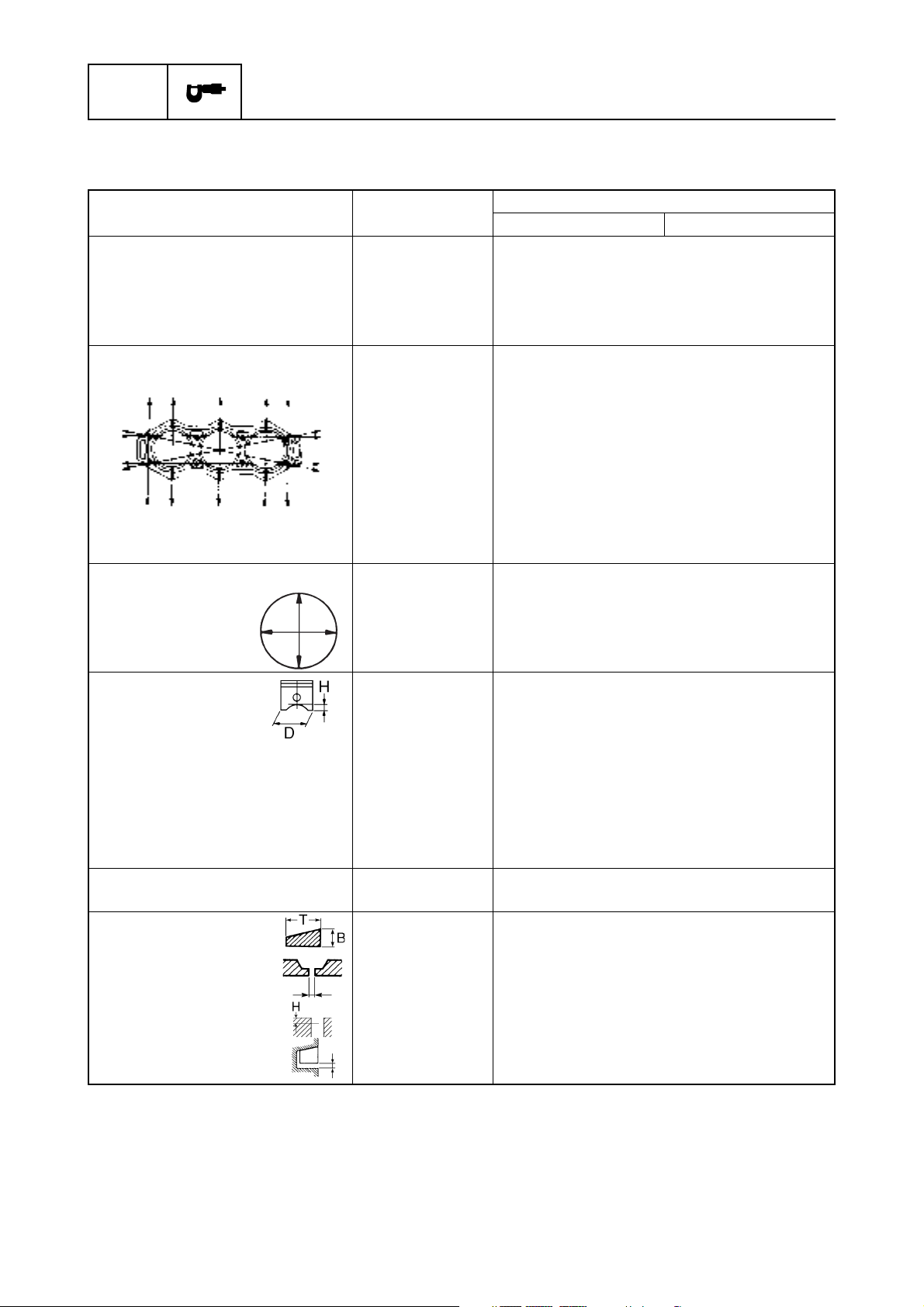
Cylinder heads
Warpage limit
(lines indicate straightedge position)
Cylinders
Bore size
Bore size limit
Taper limit
Out-of-round limit
Pistons
Piston diameter (D)
Measuring point (H)
Piston pin boss inside diameter
Oversize piston
1st
Oversize piston diameter
2nd
Oversize piston diameter
Piston pins
Outside diameter
Piston rings
Top ring, 2nd ring
Dimension B
Dimension T
End gap
Measuring point (H)
Side clearance
kPa
(kgf/cm2, psi)
kPa
2
(kgf/cm
, psi)
mm (in)
mm (in)
mm (in)
mm (in)
mm (in)
mm (in)
mm (in)
mm (in)
mm (in)
mm (in)
mm (in)
mm (in)
mm (in)
mm (in)
mm (in)
mm (in)
mm (in)
mm (in)
Model
200AET L200AET
700 (7.0, 101.5)
520 (5.2, 75.4)
0.1 (0.04)
90.00 - 90.02 (3.5433 - 3.5441)
90.10 (3.5472)
0.08 (0.0031)
0.05 (0.0020)
89.895 - 89.915 (3.5392 - 3.5400)
10 (0.39)
23.074-23.085 (0.9084-0.9089)
+ 0.25 (0.0098)
90.145 - 90.165 (3.5490 - 3.5498)
+ 0.5 (0.0196)
90.395 - 90.415 (3.5589 - 3.5596)
23.065 - 23.070 (0.9081 - 0.9083)
1.97 - 1.99 (0.0776 - 0.0783)
2.7 - 2.9 (0.1063 - 0.1142)
0.3 - 0.4 (0.0118 - 0.0157)
20 (0.79)
0.02 - 0.06 (0.0008 - 0.0024)
* Measuring conditions:
Ambient temperature 20°C (68°F), wide open the throttle valve and the choke valve, with plugs
disconnected from all cylinders.
The figures are for reference only.
2-3
60H5E11

Maintenance specifications
Item Unit
Connecting rods
Small-end inside diameter
Big-end inside diameter
Big-end side clearance
Small-end axial play limit
Crankshaft
Crankshaft journal Diameter
Crank pin Diameter
Run-out limit
Thermostats
Opening temperature
Fully open temperature
Valve open lower limit
Carburetor
ID mark
Main jet
Main air jet
Pilot jet
Pilot air jet
Pilot screw
Float height (with gasket)
Engine idle speed
Reed valves
valve stopper height
warpage limit
mm (in)
mm (in)
mm (in)
mm (in)
mm (in)
mm (in)
mm (in)
°C (°F)
°C (°F)
mm (in)
#
#
#
#
turns out
mm (in)
r/min
mm (in)
mm (in)
Model
200AET L200AET
28.070 - 28.082 (1.1051 - 1.1056)
46.010 - 46.025 (1.8114 - 1.8120)
0.12 - 0.26 (0.0047 - 0.0102)
2.0 (0.08)
53.975 - 53.991 (2.1250 - 2.1256)
35.985 - 36.000 (1.4167 - 1.4173)
0.03 (0.0012)
50 (122)
60 (140)
3.0 (0.12)
64E01
No.1,3:150 / No.2,4:154 / No.5:152 / No.6:158
270
84
60
1 1/8 ± 1/4 (7/8 - 1 3/8)
15.5 - 16.5 (0.61 - 0.65)
675 - 725
6.5 (0.26)
0.2 (0.08)
2
Lower unit
Item Unit
Gear backlash
Pinion-to-forward gear
Pinion-to-reverse gear
Pinion shims
Forward gear shims
Reverse gear shims
Propeller shaft shims
Drive shaft
Run-out limit
Propeller shaft
End play
mm (in)
mm (in)
mm
mm
mm
mm
mm (in)
mm (in)
Model
200AET L200AET
0.25 - 0.46 0.21 - 0.43
(0.0098 - 0.0181) (0.0083 - 0.0169)
0.74 - 1.29 0.98 - 1.30
(0.0291 - 0.0508) (0.0386 - 0.0512)
0.10, 0.12, 0.15, 0.18, 0.30, 0.40, 0.50
0.10, 0.12, 0.15, 0.18, 0.30, 0.40, 0.50
0.10, 0.12, 0.15, 0.18, 0.30, 0.40, 0.50
— 0.10, 0.12, 0.15, 0.18,
0.30, 0.40, 0.50
0.1 (0.0039)
— 0.25 - 0.35
(0.0098 - 0.0138)
60H5E11
2-4
SPEC
Electrical
General Information
Item Unit
Ignition system
Ignition timing
(standard ignition timing)
(full advance)
Piston position
(full advance)
Pulser coil output peak voltage
(W/B - W/L, W/Br - W/Y, W/G - W/R)
at cranking 1(*1)
at cranking 2(*1)
at 1,500 r/min
at 3,500 r/min
Pulser coil resistance(*2)
(W/B - W/L, W/Br - W/Y, W/G - W/R)
Charge coil output peak voltage
(Br - R)
at cranking 1(*1)
at cranking 2(*1)
at 1,500 r/min
at 3,500 r/min
(L - B/R)
at cranking 1(*1)
at cranking 2(*1)
at 1,500 r/min
at 3,500 r/min
Charge coil resistance(*2)
(Br - R)
(L - B/R)
CDI unit output peak voltage
(B/W - B)
at cranking (loaded)
at 1,500 r/min
at 3,500 r/min
Spark plug gap
Ignition spark gap
Spark plug cap resistance
Ignition coil resistance
Primary coil (B/W-B)
Secondary coil (LEAD-B)
Thermoswitch
ON
OFF
Choke solenoid
Resistance
Degree
Degree
mm (in)
V
V
V
V
Ω
V
V
V
V
V
V
V
V
Ω
Ω
V
V
V
mm (in)
mm (in)
Ω
Ω at 20°C (68°F)
Ω at 20°C (68°F)
°C (°F)
°C (°F)
Ω
Model
200AET L200AET
ATDC 7
BTDC 18
2.05 (0.0807)
2.5
2.0
9.5
16.0
256 - 384
80
90
165
165
30
30
160
165
428 - 642
64.4 - 96.6
65
140
135
1.0 - 1.1 mm (0.039 - 0.043 in)
6 (0.24)
4.0 - 6.0
0.18 - 0.24
3.26 - 4.88
84 - 90 (183 - 194)
60 - 74 (140 - 165)
3.4 - 4.0
(*1) Cranking 1: unloaded Cranking 2: loaded
(*2) The figures are for reference only.
2-5
60H5E11
Maintenance specifications
Item Unit
Starter motor
Type
Output
Cranking time limit
Brushes
Standard length
Wear limit
Commutator
Standard diameter
Wear limit
Mica
Standard undercut
Wear limit
Charging system
Fuse
Lighting coil output peak
voltage (G - G/W)
at cranking(*1)
at 1,500 r/min(*1)
at 3,500 r/min(*1)
Lighting coil resistance(*2)
(G - G/W)
Rectifier Regulator output
peak voltage (R - B)
at 1,500 r/min(*1)
at 3,500 r/min(*1)
Charging current
Power trim and tilt system
Trim sensor
Setting resistance
Resistance (P - B)
Fluid type
Brushes
Standard length
Wear limit
Commutator
Standard diameter
Wear limit
Hydraulic pressure (UP)
(DOWN)
kW
Second
mm (in)
mm (in)
mm (in)
mm (in)
mm (in)
mm (in)
A
V
V
V
Ω
V
V
V, A
at 6,000 r/min
Ω
Ω
mm (in)
mm (in)
mm (in)
mm (in)
MPa (kgf/cm
MPa (kgf/cm
Model
200AET L200AET
Bendix
1.1
30
17 (0.67)
10 (0.39)
2
33 (1.30)
32 (1.26)
0.8 (0.031)
0.2 (0.008)
20
3
20.0
50.0
0.20 - 0.30
18
45
12, 14
9 - 11
9 - 379
ATF Dexron II
9.8 (0.386)
4.8 (0.189)
22 (0.87)
21 (0.83)
2
)
2
)
10 - 12 (100 - 120)
6 - 9 (60 - 90)
(*1) Unloaded
(*2) The figures are for reference only.
60H5E11
2-6
SPEC
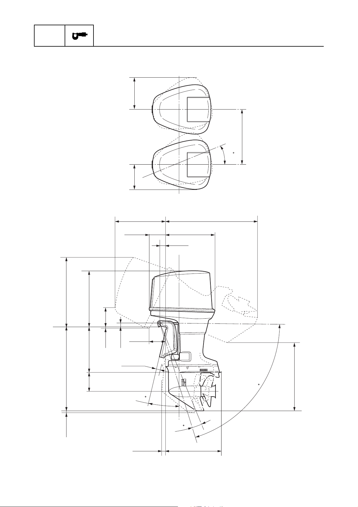
Dimensions
Exterior
General Information
426(16.8)
300(11.8)
569(22.4)
mm(in)
660(26.0)
35
L: 1,032(40.6)
X: 1,144(45.0)
788(31.0)
L: 516(20.3)
L: 946(37.2)
X: 1,072(42.2)
631(24.8)
205(8.1)
26(1.0)
X: 642(25.3)
210(8.3)
173(6.8)
45(1.8)
L: 48(1.9)
X: 61(2.4)
12
543(21.4)188(7.4)
74(2.9)
70
L: 762(30.0)
X: 837(33.0)
2-7
31(1.2)
L: 54(2.1)
X: 62(2.4)
4
634(25.0)
60H5E11
 Loading...