

Yamaha JW-II Service Manual
SERVICE MANUAL
[XA41, XA42, XA43]
XA4-28197-00 (English)
Electric power-assist unit for wheelchairs
This manual has been compiled as a guide to installing the on commercial wheelchairs, and providing after-sales service. Information which duplicates that contained in the
Service Manual has been omitted.

Introduction
This service manual describes ordinary inspections and adjustments, as well
as assembly procedures.
April 1999
The symbols noted below are used in this manual to indicate items which are necessary in order to
handle the product correctly, and to carry out inspections and servicing.
This indicates a precaution concerning safety.
WARNING
Indicates that misuse may lead to death or severe injury.
CAUTION:
Indicates that misuse may lead to injury or material damage.
NOTE: Indicates proper operation and points regarding inspection and maintenance.
Yamaha Motor Co., Ltd.
New Business Development Division
• The contents and specifications noted in this manual are subject to change without notice, due
to improvements.
• Photographs and contents may differ from the actual products in some respects, based on
changes in specifications and other factors.
• This Service Manual is intended for use by persons with basic knowledge and skills.
• Persons without general knowledge and expertise in the servicing of the product should not
carry out inspections, adjustments, disassembly, assembly, or other procedures relying simply
on this Service Manual.
This can result in problems with servicing, and in damage to the equipment and other problems.

Index
Introduction ...................................................................................... 1
Model Variations .................................................................................. 1
Principal Specifications ............................................................................... 2
Special Tools/Supplemental Materials ........................................................ 3
Tightening Torques for Principal Portions ................................................... 4
Installation: Preparation....................................................... 5
Basic Judgment Concerning Applicability of ........................................ 5
Parts Supplied in the Same Package.......................................................... 6
Tools Required/Installation Based on Wheelchair Type ............................. 7
Installation Based on Wheelchair Type ....................................................... 8
Optional Parts ............................................................................................. 9
Others ....................................................................................................... 10
Installation: Procedure ........................................................ 11
Detachable Type ....................................................................................... 11
Fixed Type ................................................................................................ 14
Installation: Inspection And Adjustment
After Installing
.............................................................................. 15
Inspection Points and Adjustment Points .................................................. 15
Service At Delivery .................................................................. 19
Outline of the Running Control System ..................................................... 19
Explaining
Operation Characteristics to the User .............................. 21
Battery.................................................................................................. 24
Names of Parts and Circuits ..................................................................... 24
Construction and Characteristics of Nickel Hydrogen Batteries................ 25
Battery Construction and Characteristics .................................................. 26
Battery Functions ...................................................................................... 29
Battery Charger........................................................................... 35
Names and Functions of Parts .................................................................. 35
After Service .................................................................................. 39
Self diagnosis function .............................................................................. 39
What to do When LED Warning Light is ON ............................................. 40
Adjustment Points When Replacing Wheels ............................................. 41
Ordering Parts ........................................................................................... 42

1
Introduction Model Variations
•
The is available in nine variations. Please be careful to order the specific model
desired.
Variations and Principal specifications
Model Name Assist Axle Tire Size Hand Rim Catalogue
Type Ratio Indication
-24S 1.5
Detachable Type
24×1 3/8 WO SUS
-24SR ↑ Fixed type ↑↑
XA41
-22S ↑
Detachable Type
22×1 3/8 WO ↑
A type
-22SR ↑ Fixed Type ↑↑
-24K 3
Detachable Type
24×1 3/8 WO
Vinyl chloride coating
-24KR ↑ Fixed Type ↑↑
XA42
-22K ↑
Detachable Type
22×1 3/8 WO ↑
B type
-22KR ↑ Fixed Type ↑↑
XA43 -22CR 3.7 ↑ 22×1 3/8 WO
SUS (for 20-inch tires)
C type
Reference
<Model designation>
Example -22 K R
R: Type with the wheels fixed with nuts. (Those
without the R have detachable wheels.)
K: Type recommended for users with weak grasp-
ing power (ex: quadriplegia). (catalogue indication: B type) The power assist function will work
with weak manual operation input. Hand rims
are vinyl chloride coated.
S: Type recommended for those with sufficient
grasping power (ex: paraplegia). (catalogue indication: A type) The power assist function will
work after with sufficient manual operation in
put. Stainless steel hand rims.
C: This type is recommended for persons capable
of operating with one hand (ex. hemiplegia).
(catalogue indication: C type)
Steering is done with a foot.
22: Tires with nominal diameter of 22 inches.
24: Tires with nominal diameter of 24 inches.
<Selecting Specifications>
The wheelchair should be tried by the user before the final specifications are decided.
• Notes for test use:
1. On an indoor level course, users will judge type B to be easier to use, because of no appreciable
differences between types A and B. Therefore, an outdoor course with a slope of approximately
4° is recommended.
2. Users should test types A and B under varying conditions, including indoor and outdoor use, and
on inclined surfaces and level surfaces where travel is likely to be particular fast or slow.
<
<
<

2
Introduction
• Guidelines for selecting type A or B or C
1. A type is suitable for those who are capable of grasping the hand rims (such as paraplegics) and
have enough strength to travel easily up a slope of about 4° (inclination of a slope inside a building). Users with this much strength may not like the way uphill travel feels with the type B model,
because the hand rims feel loosely mounted.
2. B type is suitable for those who are incapable of grasping the hand rims (such as quadriplegics)
and have difficulty traveling up a slope of about 4° manually by themselves. Slopes will become
easier if climbed slowly. If these users use the A type, they will not be able to use the power assist
function effectively, since they are incapable of pushing the hand rims sufficiently.
✽ If the user tests the type B model and feels that there is a sense of scraping bottom when the
hand rims are turned slightly forcefully, the type A model is more suitable. The type A model
should be test-ridden before the final specifications are decided.
3. The C type is designed for persons who are able to operate one hand rim with one hand and to
steer with one foot (such as hemiplegia). (Steering cannot be done by the hand rim alone.)
Model Variation/
Principal Specifications
XA41 (catalogue indication: A type)
XA42 (catalogue indication: B type)
XA43 (catalogue indication: C type)
A and B types 15.8 Kg
C type 17.2 Kg
22×1 3/8WO (tire outer diameter: 570 ± 3 mm)
24×1 3/8WO (tire outer diameter: 608 ± 3 mm)
Direct current brush type motor
24 V
90 W×2 (Left wheel × 1, right wheel × 1)
A and B types Approx. 15 km
C type Approx. 10 km
(For continuous travel on a level surface at 5 km/h,
the C type is 3.5 km/h.)
A and B types 0 to 6 km/h
C type 0 to 4 km/h
Microcomputer control
Belt + gear type (rear wheel direct drive)
Right and left hand rim steering. (C: Foot)
Brake assist + manual wheelchair brake
Nickel-Hydrogen battery (fast-charging type)
Two 1.2 V × 20-cell batteries connected in series, 24 V
6.7 Ah (5-hour ratio)
2.9 Kg
JWC-2
AC 100 ~ 240 V, multi-input
50/60 Hz
Fast 2.6 A trickle 100 mA
Forced air-cool
0 to 40°C (battery temperature)
2.5 to 3.0 h
30A blade-type micro-fuse
Competition silver
Circuit silver
Model Type
Unit Weight
Tire Size (2 types): nominal diameter of 22 inches
nominal diameter of 24 inches
Power Assist Unit: Model Type
Rated Voltage
Rated Output
Travel Distance After Single Charge
Range of Assisted Speeds
Control
Drive
Steering
Braking
Battery: Model Type
Nominal Voltage
Nominal Capacity
Weight
Charger: Model Type
Input Voltage
Input Frequency
Charging Current
Cooling Method
Range of Temperature at Start of Charging
Charging Time
Overcurrent Interception
Coloring: Cap, Wheel and Hub Case, Transmission
Principal Specifications
3
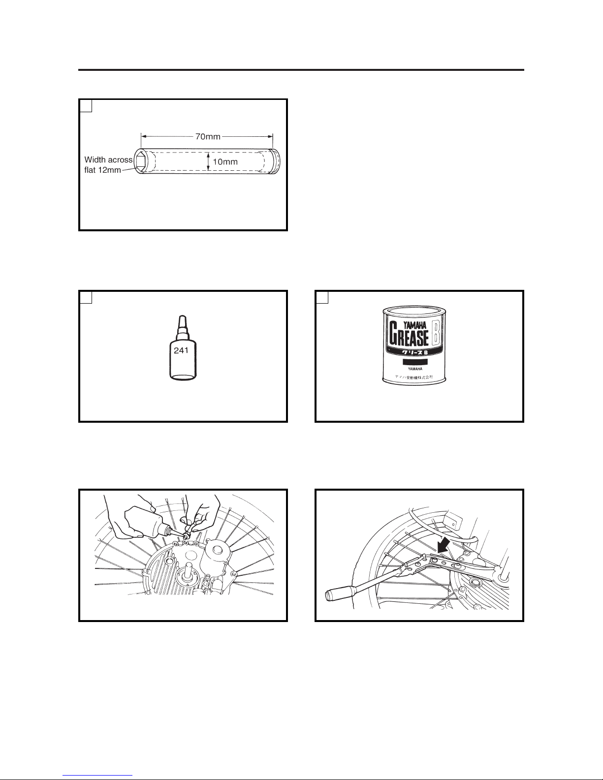
Introduction Special Tools/Supplemental Materials
Deep socket wrench with 10 mm bore (market
product)
This is necessary when tightening the stopper with
the torque wrench.
1
Thread lock Locktite 241
To be applied to threaded portions that easily come
loose, such as screws for stoppers, as in the figure
below.
Grease B (general type) 90890-69916
General waterproof grease can be used on sliding
portions, spin axis bearings, and gear contact
portions.
2
Supplemental Materials
• Where to apply thread lock
1. Threaded portion of the stopper
Degrease the threaded portion before applying thread
lock.
Special tools
2. Threaded portion of the main switch
3. Threaded portion of installation bolt for the
pipe outer (hand rim).
1
4
Introduction
•
The following portions around the axle area are related to safety. When installing the unit, make
sure these are sufficiently tightened, in the range specified below. If the tightening torque is too
loose, there is a danger of loosening, and if tightening is too tight, there is a danger of breakage.
Tightening Torques for
Principal Portions
Tightening portion
Detachable axle nut
Fixed axle flange nut
Stopper (torque stop) bolt
Clamp bracket Ass’y bolt
Bracket clamp bolt
Main switch angle adjusting bolt
Main switch length adjusting screw
Bracket battery mounting bolt
1
2
3
4
5
6
7
8
Tool size
24 mm socket
17 mm deep socket
12 mm deep socket
12 mm socket
5 mm hexagon socket
4 mm hexagon socket
5 mm hexagon socket
12 mm deep socket
Tightening torque
40 to 50 N·m (400 to 500 kgf·cm)
40 to 50 N·m (400 to 500 kgf·cm)
8.5 to 12 N·m (85 to 120 kgf·cm)
12 to 15 N·m (120 to 150 kgf·cm)
7.5 to 12 N·m (75 to 120 kgf·cm)
8 to 12 N·m (80 to 120 kgf·cm)
7.5 to 12 N·m (75 to 120 kgf·cm)
11 to 13 N·m (110 to 130 kgf·cm)
Remarks
Apply thread lock
Apply thread lock
Apply thread lock
1
2
43
65
87
5
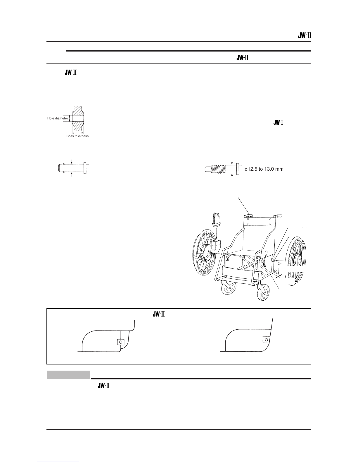
NOTE:
Please be aware that there are wheelchairs in the market on which the cannot be installed.
• The can be installed on wheelchairs which meet all of the following conditions.
1. JIS standard vehicles with a tire size of 22 or 24 inches.
2. Wheelchairs with one back pipe with a pipe diameter of ø19 to 26 mm.
3. The diameter of the axle hole and boss thickness are as follows.
<Detachable type> <Fixed type>
Hole diameter: 16, 18 and 20 mm Hole diameter: 12.5 to 13.5 mm
(same with
)
Boss thickness: 30 mm or below Boss thickness: 30 mm or below
(28 mm recommended) (28 mm recommended)
4. Axle diameter
<Detachable type> <Fixed type>
ø12.7 mm
5. The distance from the center of the axle hole
to the base pipe must be 105 mm or more,
and there must be 43 mm or more of space
in front of the back pipe.
6. Non-reclining type
Installation: Preparation
Basic Judgment Concerning
Applicability of
Example of a wheelchair on which the cannot be installed
CAUTION:
Do not install the on a wheelchair that has been in use for a long time and is no longer
durable.
Examples:
• Deformation or weakness is observed in rivet portions, bolt tightening portions,
and casters.
• Corrosion or wear is observed.
• Wheelchair that has been in use for 4 years or more.
Push handle pipe
Back pipe
Axle hole
105 mm or more
43 mm
Base pipe
• Pipe in the rear • Eccentricity in the back pipe and axle hole
6
Installation: Preparation
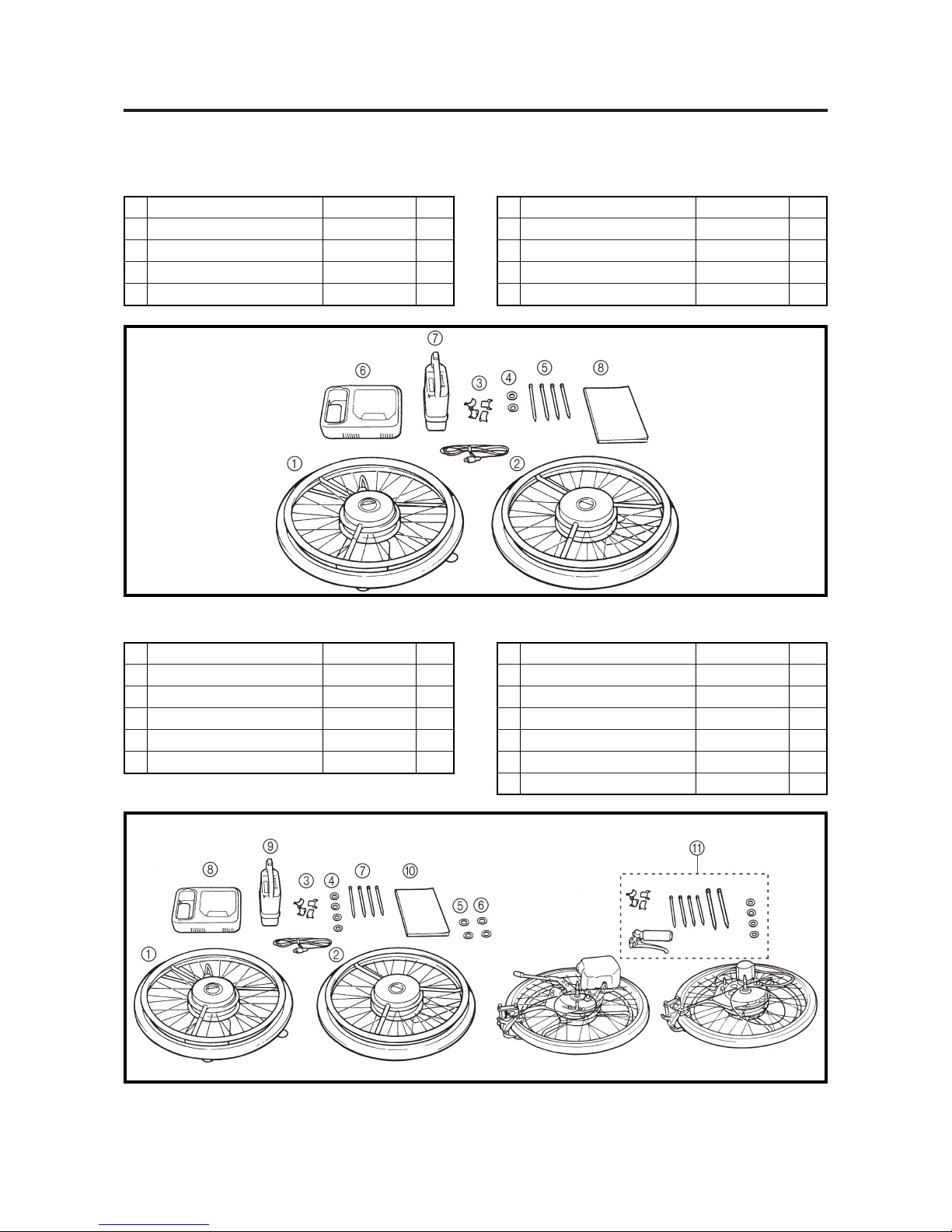
Parts Supplied in
the Same Package
No. Name Part Number
Quantity
1
Right (wheel + tilt lock) assembly
1
2
Left (wheel + tilt lock) assembly
1
3 Spacer (for ø 22 mm) XA3-43141-00 4
4 Washer (for adjustment) 92907-18600 2
No. Name Part Number
Quantity
5 Clamp 90465-10098 4
6 Battery charger XA4-82107-00 1
7 Battery assembly XA4-82110-00 1
8 Manual set
✽ 1
• Standard supplied parts differ to some extent, depending on whether the wheels are
detachable or fixed.
• Detachable type (22S, 24S, 22K, 24K)
• Fixed type (22SR, 24SR, 20KR, 22KR, 24KR, 22CR)
Detachable type
No. Name Part Number
Quantity
1
Right (wheel + tilt lock) assembly
Differs from detachable type
1
2
Left (wheel + tilt lock) assembly
Differs from detachable type
1
3 Spacer (for ø 22 mm) XA3-43141-00 4
4 Washer (for adjustment) 92903-12200 4
5 Washer (tilt lock hole spacer) 90201-12541 2
No. Name Part Number
Quantity
6 Washer (for adjustment) 92907-18600 2
7 Clamp 90465-10098 4
8 Battery charger XA4-82107-01 1
9 Battery assembly XA4-82110-00 1
0 Manual set ✽ 1
A Auxiliary brake set C type only 1
Fixed type
✽ Manual set A type: XA4-W2819-00
B type: XA4-W2819-50
C type: XA4-W2819-80
7
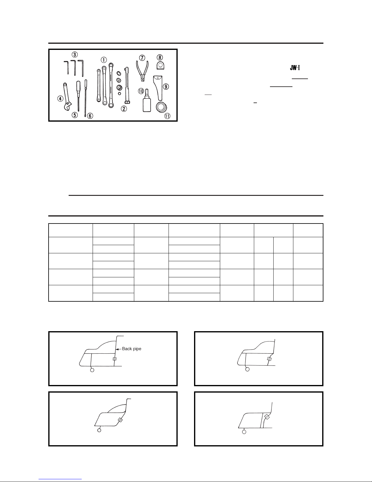
• The following tools are required.
(Those items which are not underlined
are identical to those of the
.)
1 Closed wrench (12-14) (14-17) (22-24)
2 Torque wrench, socket (
12 deep) (17 deep)
(
24) (5mm hexagon)
3 Hexagon wrench (
2) (4) (5)
4 Monkey wrench
5 Driver (plus, medium size)
6 Driver (minus, small size with long shaft)
7 Nipper (one blade)
8 Measurer
9 Vernier calipers
0 Thread lock
A Grease
Installation: Preparation
Tools Required/Installation Based on
Wheelchair Type
Tire Size (inch)
24
22
24
22
24
22
24
22
Frame Type
Standard type
Sports Type
Offset Axle Type
Module Type
• At delivery, this is set to the standard type.
Battery
Bracket Angle
E
F
F
F
Length of the
Main switch
Extended
Standard setting
Extended
Standard setting
Extended
Standard setting
Extended
Standard setting
Angle of the
Main switch
3
8
3
3
Position of the
Clamp Bracket
Front
Rear
Front
Rear
Position of the
Stopper
Left Right
25
Left Right
26
Left Right
26
Left Right
26
• Preparation for installation
NOTE:
Before installing, change the mounting position of the parts to match the wheelchair type, following the
chart below. The chart may not conform to some wheelchairs.
Frame Type
Standard Type
Back pipe and axle mounting portion pipe are in a
straight line.
Offset Axle Type
Angle difference between the back pipe and axle
mounting portion pipe is small.
Sports Type
Angle difference between the back pipe and axle
mounting portion pipe is large.
Module Type
Angle difference is large, as in the sports type.
8
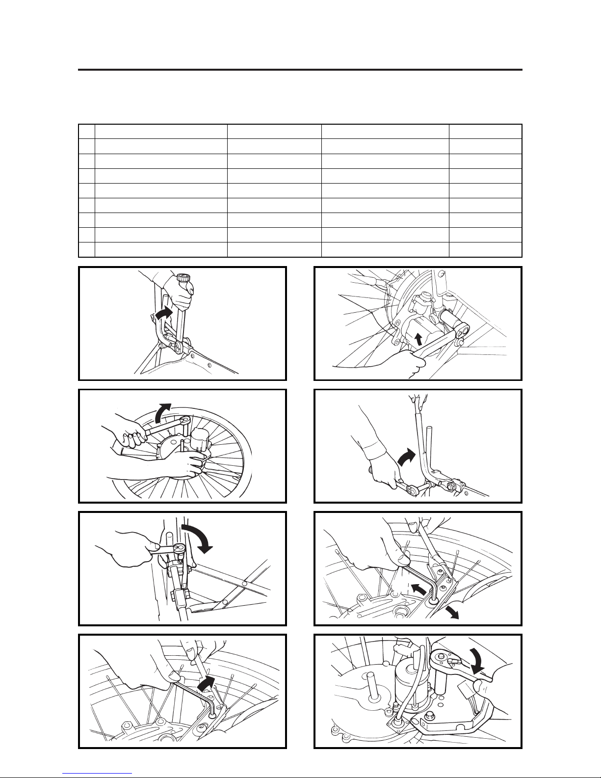
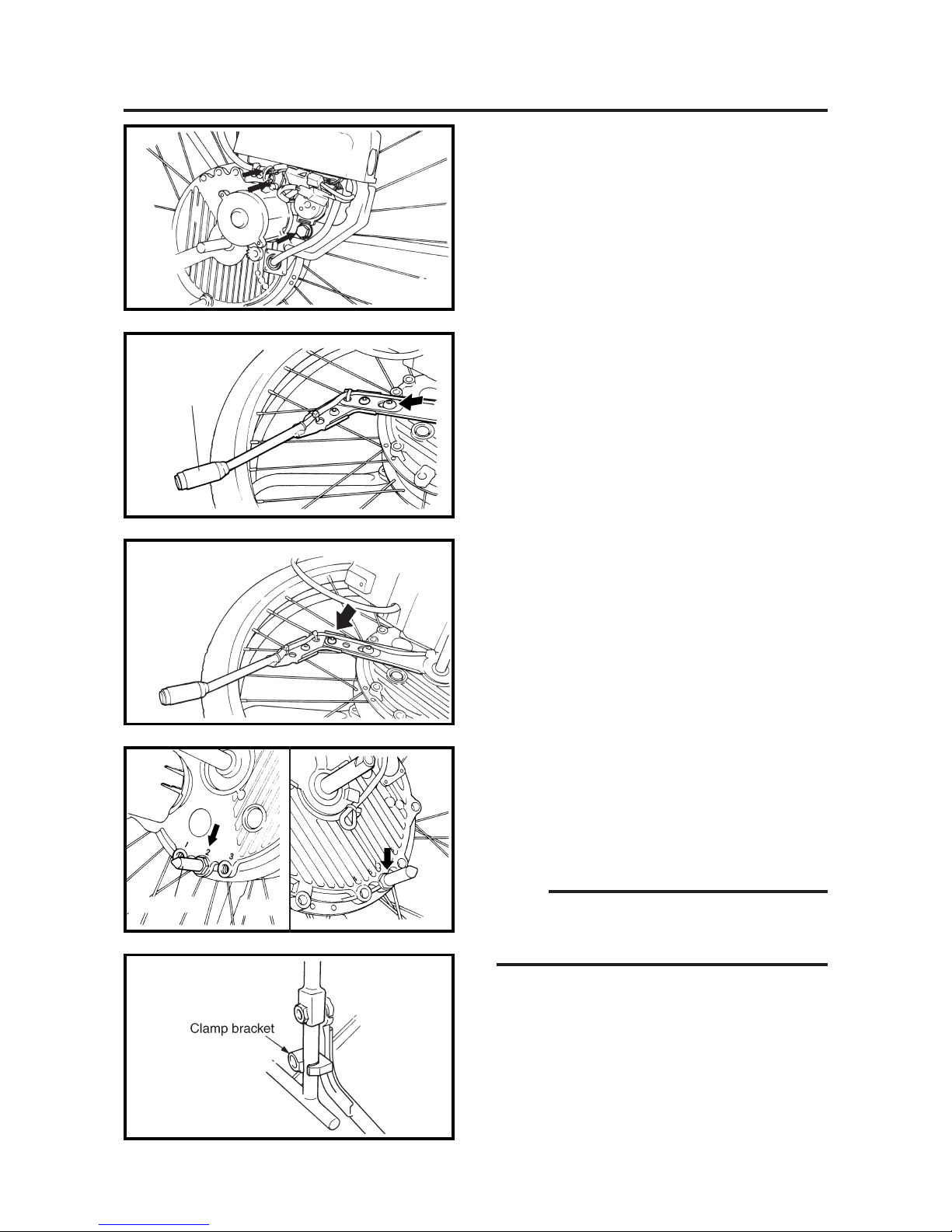
Installation: Preparation
1. Angle adjustment of the battery bracket
If the battery box is sharply tilted when the
wheel assembly is installed, remove the
three bolts indicated by the arrows, and
straighten the battery box.
2. Adjustment of the main switch length
and angle
Adjust the level position until the switch lever button is easy to operate, when doing
this, adjust the positioning of the wires as
well.
3. Adjustment of the stoppers
At delivery, the stoppers are installed in position 2 for the left and position 4 for the
right. For the sports type, change the stopper positions to position 1 for the left and position 6 for the right.
NOTE:
Apply thread lock to the threaded portions of the
stoppers and tighten with the specified tightening torque.
4. Position of the clamp bracket
The installed clamp bracket is shown in the
figure as the standard type, with the insert
inlet of stopper located at the back pipe front
side.
Installation Based on
Wheelchair Type
Main switch
Right side
Left side
Right side
Left side
Stopper
9
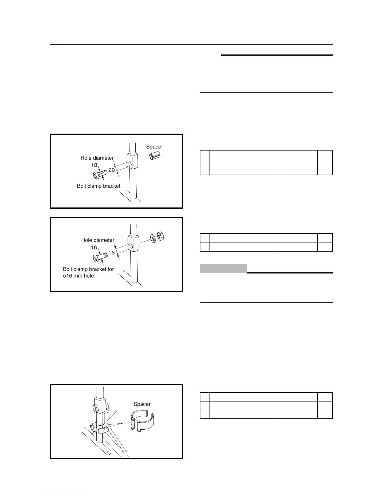
Installation: Preparation Optional Parts
NOTE:
When installing, the following parts may be
necessary, depending on the wheelchair. Please
request Yamaha for the parts when ordering
delivery.
1. Detachable type with an axle hole diameter
of 20 mm
No. Name Part Number
Quantity
1
Spacer,
tube clamp bracket 2
XA3-43142-00 4
2. Detachable type with an axle hole diameter
of 16 mm
No. Name Part Number
Quantity
1 Bolt, clamp set A
XA3-W4313-10
2
CAUTION:
Set the nut tightening torque slightly lower
than the standard.
25 to 30 N·m (250 to 300 kgf·cm)
3. Frame pipe diameter other than ø22 mm
No. Name Part Number
Quantity
2 Spacer (for ø24 mm) XA3-43141-10 4
3 Spacer (for ø19 mm) XA3-43141-20 4

10
Installation: Preparation Others
•
Other preparations
• Cleaning the wheelchair
If the wheelchair requires cleaning, this should be done before installation.
CAUTION:
The wheelchair should not be washed with water after it has been assembled, as this can cause
breakdowns.
• Retighten the various components.
Retighten the screws if there are any loose screws in the arm rests, seat, frame, or brakes.
• Initial charging
Charge the battery before starting the installation.
New batteries cannot be used without being charged. Charge the battery before starting the installation. It takes about 3 hours to charge the battery completely.
CAUTION:
When charging batteries, choose a place with good ventilation and an ambient temperature of
10 to 30°C.
• Handling the various parts
Handle the various parts with care. Parts can be damaged if they are dropped.
CAUTION:
Placing the wheel directly on the floor can damage the cap and wheel. Spread a protective cloth
under the wheel.
11
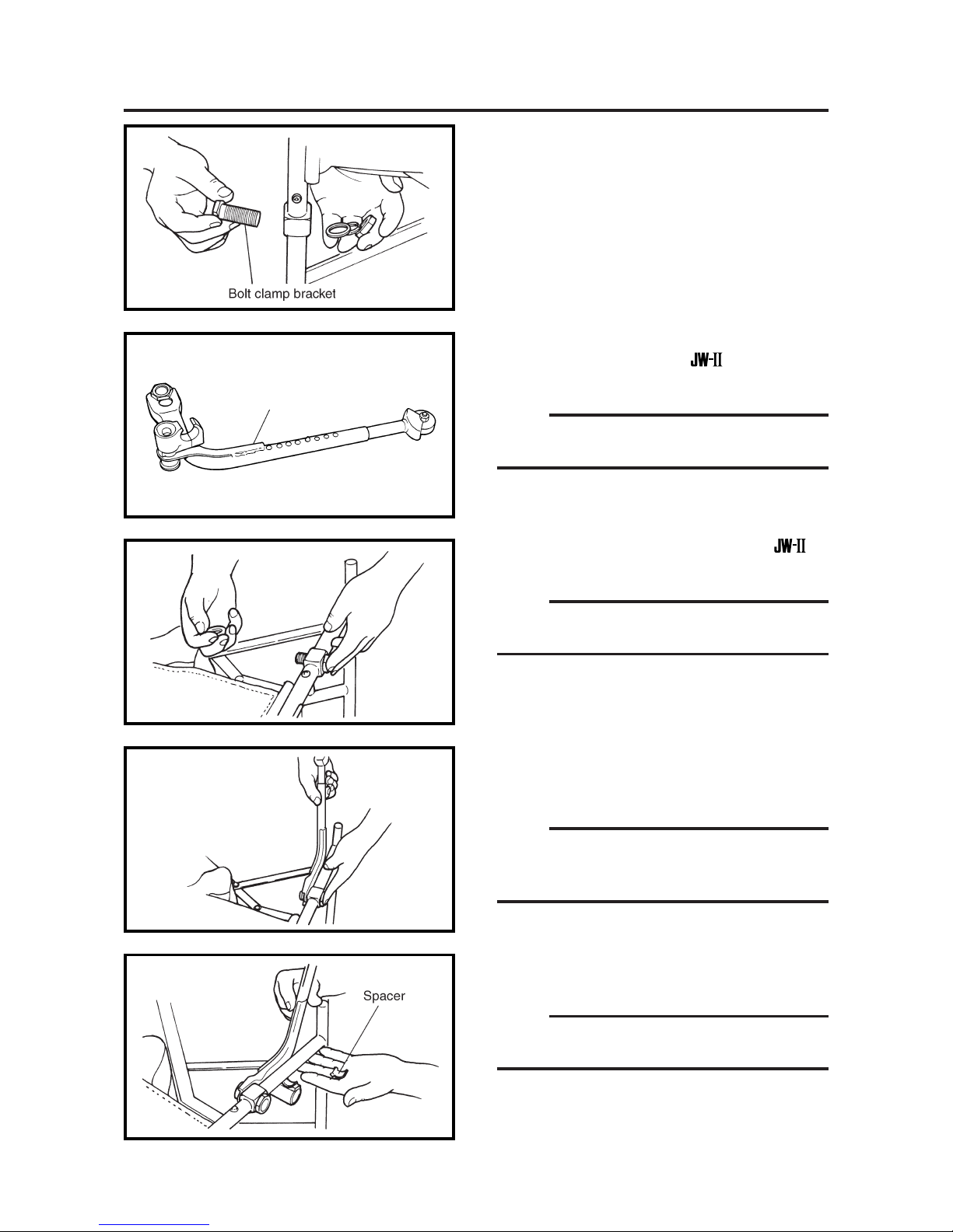
Installation: Procedure Detachable Type
1. Remove the wheel and bolt clamp bracket
from the wheelchair.
2. Remove the tilt lock assembly which is tentatively installed on the
wheel assem-
bly.
NOTE:
Place the tilt lock assembly in order to recognize
which is right and left.
3. Install the bolt clamp bracket of the on
the wheelchair frame.
NOTE:
Place the bolt head portion from the frame
outside.
4. Insert the tilt lock into the bolt clamp bracket
and apply the washer and nut. Then tighten
them tentatively.
NOTE:
The tilt lock has a longitudinal hole in it. As a
standard, the upper end of the hole should be
used.
5. Install the fitting spacer on the clamp
bracket.
NOTE:
Select a spacer which fits the pipe diameter of
the frame.
Tilt lock assembly
 Loading...