

Page 1

1987 - 1990
Downloaded from www.ScooterTime.net
MOTORCYCLE
SERVICE MANUAL
Model : CE50T, CG50A, CG50U, CG50W
2YT281972000
*2YT281972000*
Page 2
CE50T
Downloaded from www.ScooterTime.net
SERVICE MANUAL
©1986 by Yamaha Motor Co., Ltd.
1st Edition, November 1986
All rights reserved. Any reprinting or
unauthorized use without the written
permission of Yamaha Motor Co., Ltd.
is expressly prohibited.
Page 3
3
Downloaded from www.ScooterTime.net
Page 4
NOTICE
Downloaded from www.ScooterTime.net
This manual was written by the Yamaha Motor Company primarily for use by Yamaha dealers and
their qualified mechanics. It is not possible to put an entire mechanic's education into one manual,
so it is assumed that persons using this book to perform maintenance and repairs on Yamaha scooter
have a basic understanding of the mechanical concepts and procedures inherent in scooter repair tech-
nology. Without: such knowledge, attempted repairs or service to this model may render it unfit to
use and/or unsafe.
Yamaha Motor Company, Ltd. is continually striving to improve all models manufactured by Yamaha.
Modifications and significant changes in specifications or procedures will be forwarded to all Autho-
rized Yamaha dealers and will, where applicable, appear in future editions of this manual.
TECHNICAL PUBLICATIONS
SERVICE DIVISION
MOTORCYCLES OPERATIONS
YAMAHA MOTOR CO., LTD.
HOW TO USE THiS MANUAL
PARTICULARLY iMPORTANT iNFORMATiON
This material is distinguished by the following notation.
D
NOTE: A NOTE provides key information to make procedureseasier or clearer.
ili ii i iiil ACAUTIONindicatesspecialproceduresthatmustbefollowedtoavoid
damage to the scooter.
A WARNING indicatesspecial procedures that must be followed to avoid injury
to a scooter operator or person inspecting or repairingthe scooter.
MANUAL FORMAT
All of the procedures in this manual are organized in a sequential, step-by-step format. The informa-
tion has been compiled to provide the mechanic with an easy to read, handy reference that contains
comprehensive explanations of all disassembly, repair, assembly, and inspection operations.
In this revised format, the condition of afaulty component will precede an arrow symbol and the course
of action required will follow the symbol, e.g.,
• Bearings
Pitting/Damage_ Replace.
EXPLODED DIAGRAM
Each chapter provides exploded diagrams before each disassembly section for ease in identifying cor-
rect disassembly and assembly procedures.
Page 5
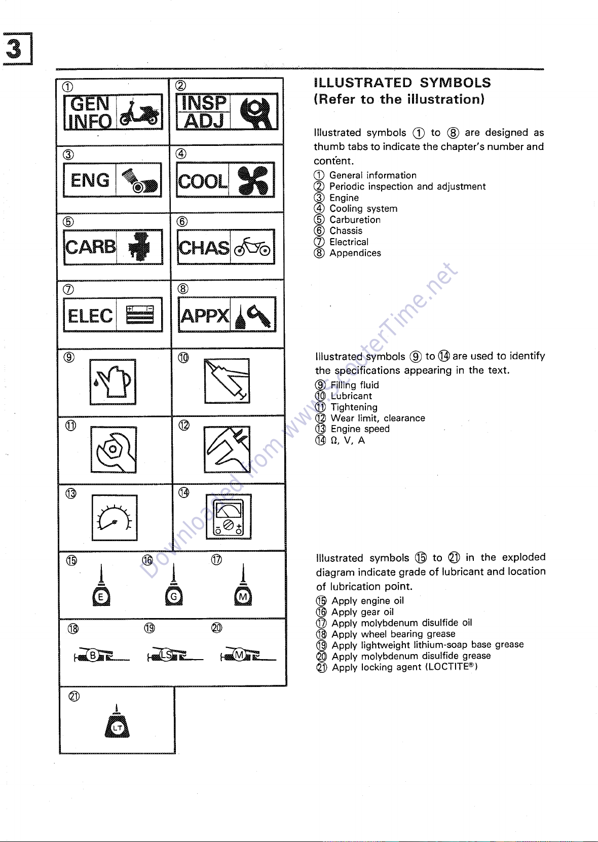
(9 ® iLLUSTRATED SYMBOLS
Downloaded from www.ScooterTime.net
IGENINFO (Refer to the illustration)
Illustrated symbols (_) to _) are designed as
thumb tabs to indicate the chapter's number and
(_ (_) content.
ENG OOL Periodic inspection and adjustment
(_ (_) _ Carburetion
ICARB[ ]_ 1 _"AS1_I _(_)_; pter'nCdl'ces
® ®
® ® _ Illustrated symbols (_ to (_) are used to identify
%_JDI IC _i General information
_ EngineCooling system
Chassis
@
6_ _ the specifications appearing in the text.
(_) Filling fluid
(_ Lubricant
(_) Tightening
_Wear limit, clearance(_) (_) -- Engine speed
@ @
® ®
.,1 _ j diagram indicate grade of lubricant and location
- _ = of lubrication point.
_ _ ® Apply engine o,1
@ (_ (_ @(_Apply molybdenum disulfide oilApply wheel bearing grease
_ _ _ _L_.._ _(_))Apply lightweight lithium-soap base grease
@
Illustrated symbols (_ to (_ in the exploded
® Apply gear oil
Apply molybdenum disulfide grease
Apply locking agent (LOCTITE ®)
®
l
m
i
Page 6
INDEX
Downloaded from www.ScooterTime.net
GENERAL,NFORMAT,ON
ENGINE OVERHAUL '_'%_
ENG _
CARBURETION
CARB_,
CHASSIS CHAS_
L..,-.-----J
ELECTRICAL ELEC_
APPENDICES APPX_
Page 7
i
Downloaded from www.ScooterTime.net
!
i
i
1
p,
Page 8
GEN
Downloaded from www.ScooterTime.net
CHAPTER 1
GENERAL INFORMATNON
SCOOTER IDENTIFICATION ....................................... B-3
VEHICLE IDENTIFICATION NUMBER .............................. B-3
ENGINE SERIAL NUMBER ....................................... B-3
IMPORTANT INFORMATION ...................................... B-3
ALl. REPLACEMENT PARTS ..................................... B-3
GASKETS, OIL SEALS, AND O-RINGS ............................ B-3
LOCK WASHER/PLATES AND COTTER PINS ..................... B-3
BEARINGS AND OIL SEALS ..................................... B-4
CIRCLIPS ...................................................... B-4
SPECIAL TOOLS .................................................. B-4
FOR TUNE-UP .................................................. B-4
FOR ENGINE SERVICE .......................................... B-4
FOR CHASSIS SERVICE ......................................... B-5
FOR ELECTRICAL COMPONENTS ................................ B-5
m
Page 9

Downloaded from www.ScooterTime.net
Page 10
INFO
Downloaded from www.ScooterTime.net
SCOOTER IDENTIFICATION
GENERAL
INFORMATION
SCOOTER IDENTIFICATION
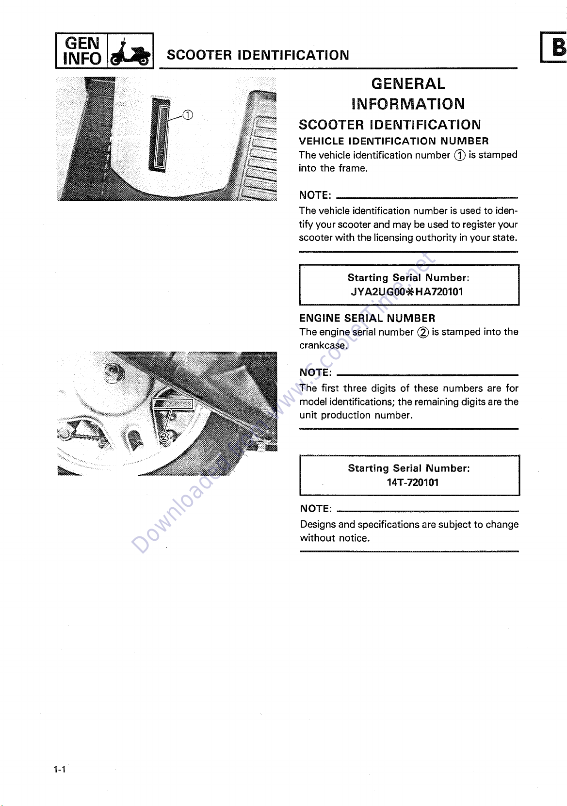
VEHICLE IDENTIFICATION NUMBER
The vehicle identification number (~ is stamped
into the frame.
NOTE:
The vehicle identification number is used to iden-
tify your scooter and may be used to register your
scooter with the licensing outhority in your state.
Starting Serial Number:
JYA2U G00-~ H A720101
ENGINE SERIAL NUMBER
The engine serial number (~ is stamped into the
crankcase.
NOTE:
The first three digits of these numbers are for
model identifications; the remaining digits are the
unit production number.
Starting Serial Number:
14T-720101
NOTE:
Designs and specifications are subject to change
without notice.
1-1
Page 11
IMPORTANT INFORMATION INFO
Downloaded from www.ScooterTime.net
I°E"
IMPORTANT INFORMATION
ALL REPLACEMENT PARTS
1. Use only genuine Yamaha parts for all
replacements. Use oiland/or grease recom-
mended by Yamaha for assembly and adjust-
ment. Other brands may be similar in func-
tion and appearance, but inferior in quality.
GASKETS, OIL SEALS, AND O-RINGS
1. All gaskets, seals, and O-rings should be
replaced when an engine is overhauled. All
gasket surfaces, oil seal lips and O-rings must
be cleaned.
2. Properly oil all mating parts and bearings dur-
ing reassembly. Apply grease to the oil seal
lips.
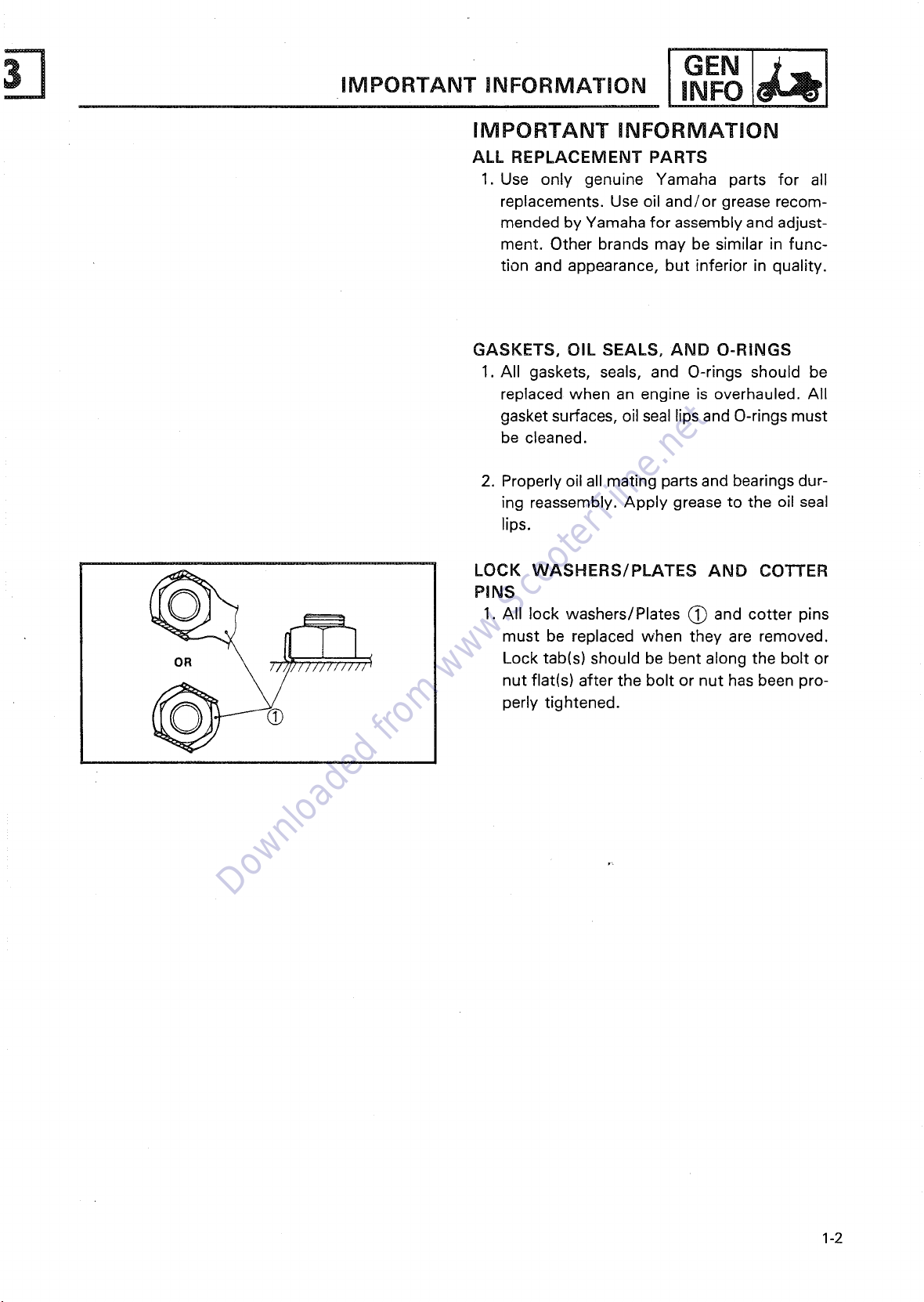
LOCK WASHERS/PLATES AND COTTER
PINS
must be replaced when they are removed.
Lock tab(s) should be bent along the bolt or
nut flat(s) after the bolt or nut has been pro-
perly tightened.
1. All lock washers/Plates (_ and cotter pins
1-2
Page 12
INFO iMPORTANT iNFORMATiON
Downloaded from www.ScooterTime.net
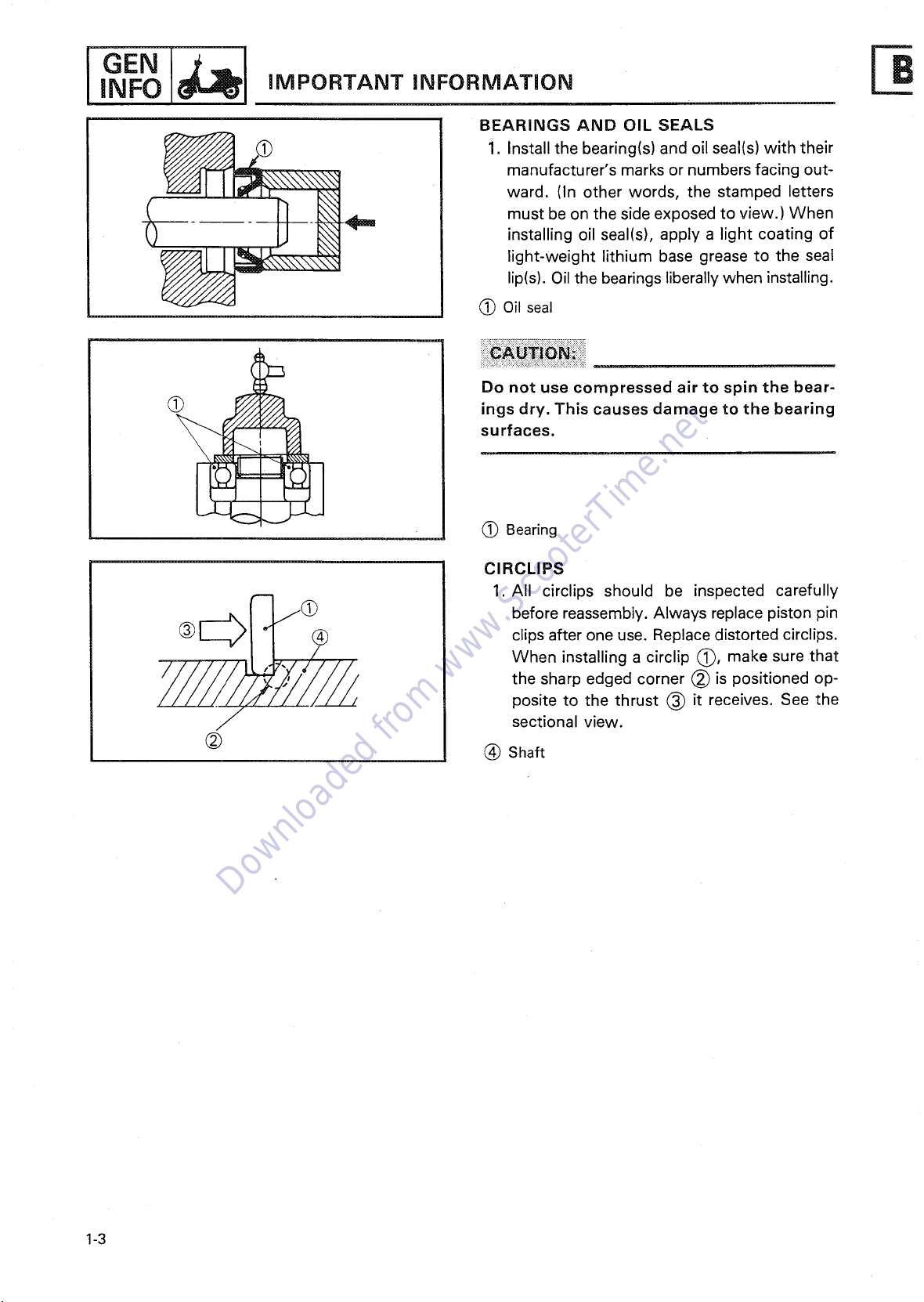
BEARINGS AND OIL SEALS
manufacturer's marks or numbers facing out-
ward. (In other words, the stamped letters
__) _ must be on the side exposed to view.) When
(_ ings dry. This causes damage to the bearing
_/._/7_/_////_ When installing a cirelip (_, make sure th at
/J sectional view.
installing oil seal(s), apply a light coating of
i. Install the bearing(s) and oil seal(s) with their
lip(s). Oil the bearings liberally when installing.
light-weight lithium base grease to the seal
(_ Oil seal
Do not use compressed air to spin the bear-
surfaces.
(_ Bearing
CIRCLIPS
1. All circlips should be inspected carefully
clips after one use. Replace distorted circlips.
e orereas ereoaceO ton
the sharp edged corner (_ is positioned op-
posite to the thrust (_) it receives. See the
(_) (_) Shaft
1-3
Page 13
3
Downloaded from www.ScooterTime.net
GEN
I
SPECIAL TOOLS I
SPECIAL TOOLS
The proper special tools are necessary for com-
plete and accurate tune-up and assembly. Using
the correct special tool will help prevent damage
caused by the use of improper tools or improvis-
ed techniques.
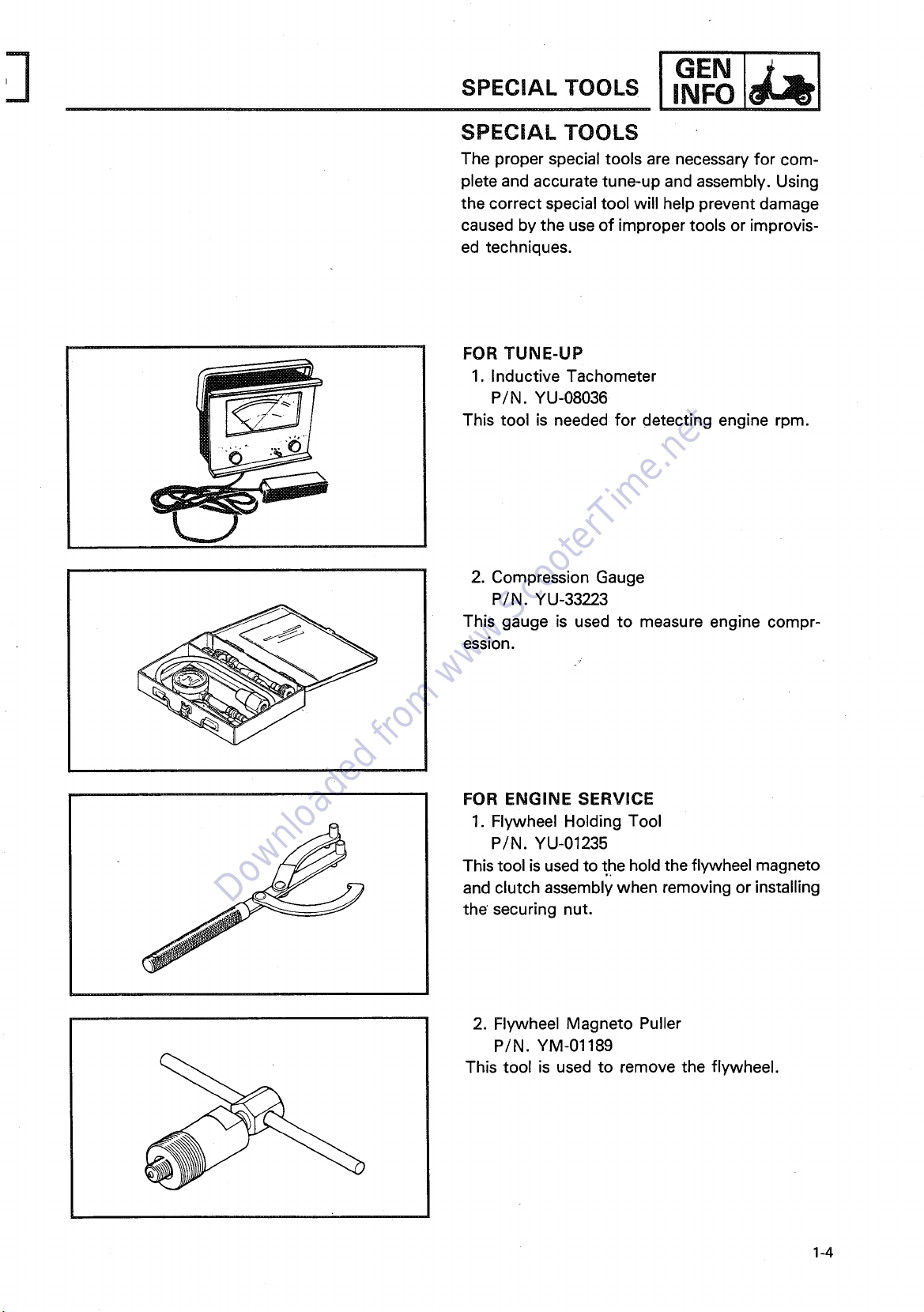
FOR TUNE-UP
1. Inductive Tachometer
P/N. YU-08036
This tool is needed for detecting engine rpm.
2. Compression Gauge
P/N. YU-33223
This gauge is used to measure engine compr-
ession.
FOR ENGINE SERVICE
1. Flywheel Holding Tool
P/N. YU-01235
This tool is used to the hold the flywheel magneto
and clutch assembly when removing or installing
the securing nut.
2. Flywheel Magneto Puller
P/N.
YM-01189
This tool is used to remove the flywheel.
1-4
Page 14
I GEN
Downloaded from www.ScooterTime.net
SPECIAL TOOLS
i ............. ir
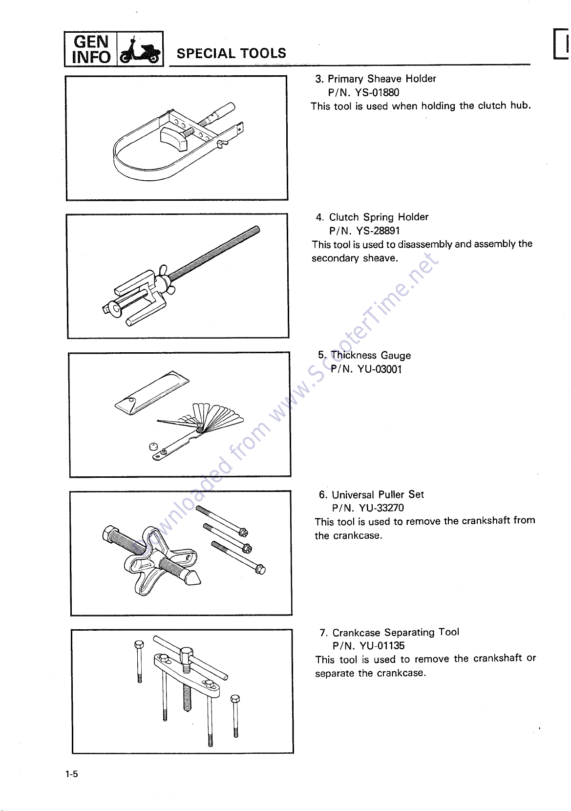
3. Primary Sheave Holder
P/N.
YS-01880
This tool is used when holding the clutch hub.
4. Clutch Spring Holder
P/N.
YS-28891
This tool is used to disassembly and assembly the
secondary sheave.
P
5.
Thickness Gauge
P/N. YU-03001
6.
Universal Puller Set
P/N. YU-33270
This tool is used to remove the crankshaft from
the crankcase.
7. Crankcase Separating Tool
P/N. YU-01135
This tool is used to remove the crankshaft or
separate the crankcase.
1-5
Page 15
I
Downloaded from www.ScooterTime.net
GEN
SPECIAL TOOLS I
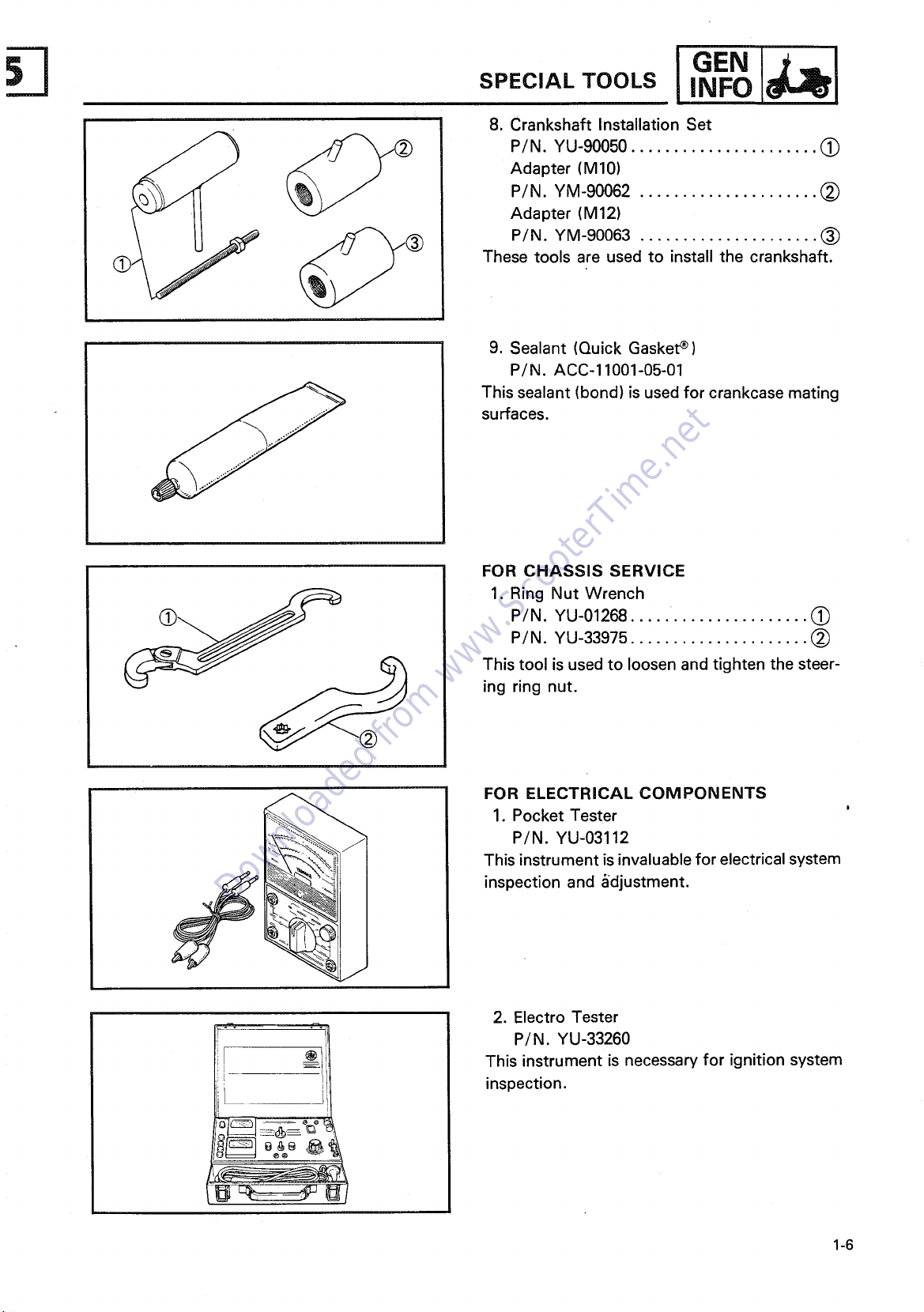
8. Crankshaft Installation Set
P/N. YU-90050 ...................... (~)
Adapter (M10)
P/N. YM-90062 ..................... (~
Adapter (M12)
P/N. YM-90063 ..................... ~)
These tools are used to install the crankshaft.
9. Sealant (Quick Gasket ~)
P/N. ACC-11001-05-01
This sealant (bond) is used for crankcase mating
surfaces.
,.Fol l
@
!J
FOR CHASSIS SERVICE
1. Ring Nut Wrench
P/N. YU-01268 (~
P/N. YU-33975 ..................... (~
This tool is used to loosen and tighten the steer-
ing ring nut.
FOR ELECTRICAL COMPONENTS
1. Pocket Tester
P/N. YU-03112
This instrument is invaluable for electrical system
inspection and §djustment.
2. Electro Tester
P/N. YU-33260
This instrument is necessary for ignition system
inspection.
1-6
Page 16
INSP
Downloaded from www.ScooterTime.net
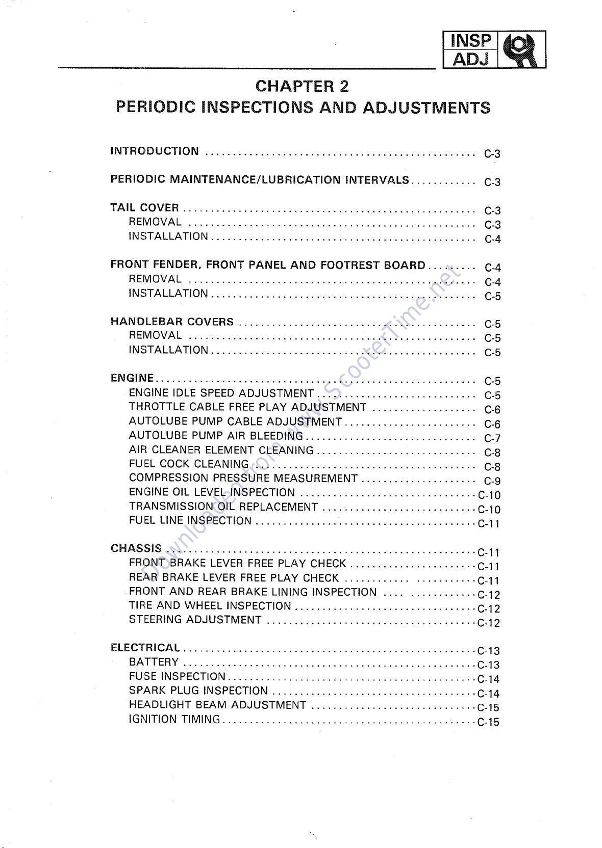
CHAPTER 2
PERiODiC iNSPECTiONS AND ADJUSTMENTS
INTRODUCTION ................................................. C-3
PERIODIC MAINTENANCE/LUBRICATION INTERVALS ............ C-3
TAIL COVER ..................................................... C-3
REMOVAL .................................................... C-3
INSTALLATION ................................................ C-4
FRONT FENDER, FRONT PANEL AND FOOTREST BOARD ......... C-4
REMOVAL .................................................... C-4
INSTALLATION ................................................ C°5
HANDLEBAR COVERS ........................................... C-5
REMOVAL ..................................................... C-5
INSTALLATION ................................................ C-5
ENGINE .......................................................... C-5
ENGINE IDLE SPEED ADJUSTMENT ............................. C-5
THROTTLE CABLE FREE PLAY ADJUSTMENT ................... C-6
AUTOLUBE PUMP CABLE ADJUSTMENT ........................ C-6
AUTOLUBE PUMP AIR BLEEDING ............................... C°7
AIR CLEANER ELEMENT CLEANING ............................. C-8
FUEL COCK CLEANING ........................................ C-8
COMPRESSION PRESSURE MEASUREMENT ..................... C-9
ENGINE OIL LEVEL INSPECTION ................................ C-10
TRANSMISSION OIL REPLACEMENT .... ........................ C-10
FUEL LINE INSPECTION ........................................ C-11
CHASSIS ........................................................ C-11
FRONT BRAKE LEVER FREE PLAY CHECK ....................... C-11
REAR BRAKE LEVER FREE PLAY CHECK ....................... C-11
FRONT AND REAR BRAKE LINING INSPECTION ................ C-12
TIRE AND WHEEL INSPECTION ................................. C-12
STEERING ADJUSTMENT ...................................... C-12
ELECTRICAL ..................................................... C-13
BATTERY ..................................................... C-13
FUSE INSPECTION ............................................. C-14
SPARK PLUG INSPECTION ..................................... C-14
HEADLIGHT BEAM ADJUSTMENT .............................. C-15
IGNITION TIMING ......................................... ..... C-15
Page 17
Downloaded from www.ScooterTime.net
Page 18
ADJ LUBRICATION iNTERVALS
Downloaded from www.ScooterTime.net
I INSPli 1 INTRODUCTION/PERIODIC MAINTENANCE/ B
PERIODIC INSPECTIONS AND ADJUSTMENTS
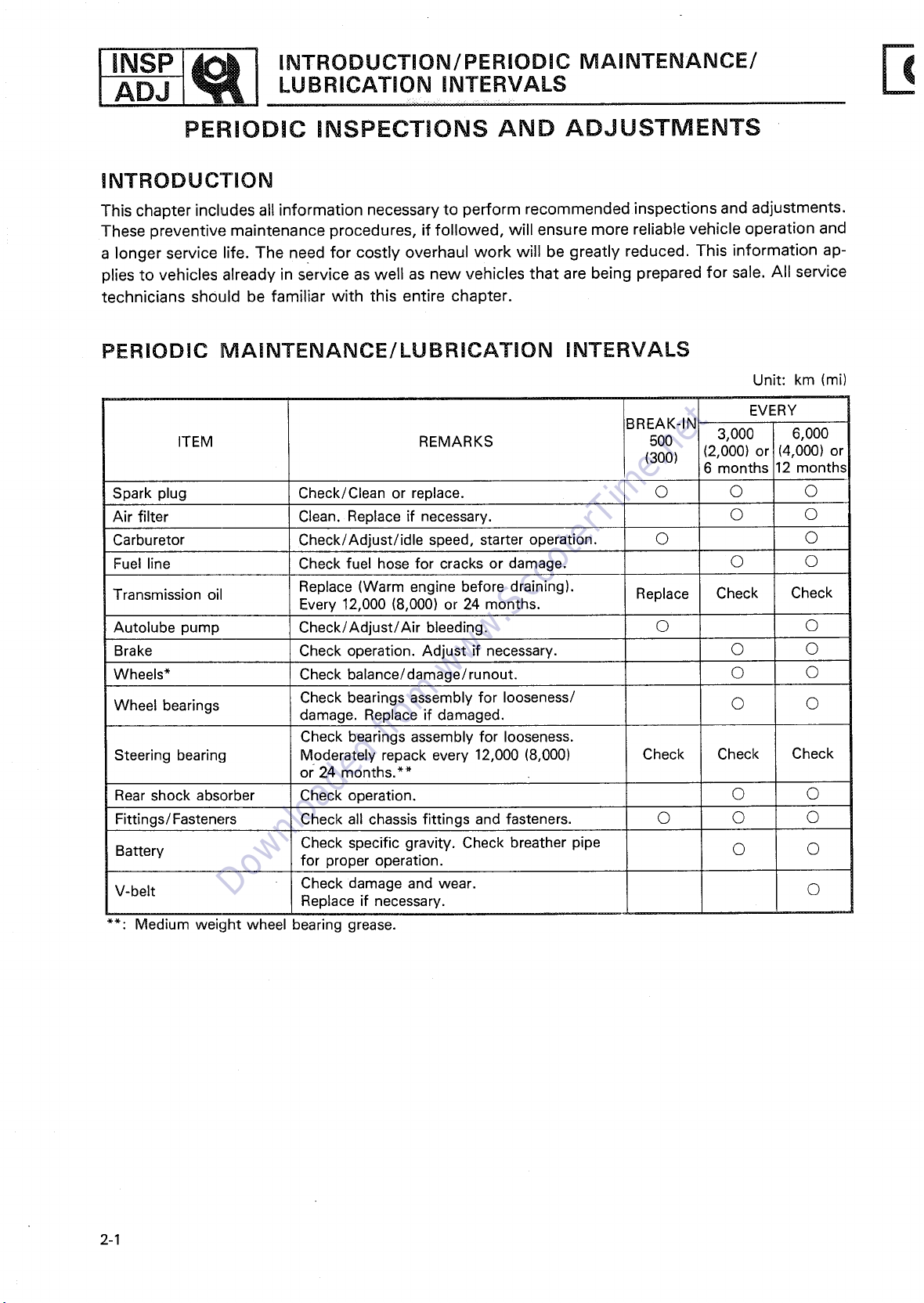
INTRODUCTION
This chapter includes all information necessary to perform recommended inspections and adjustments.
These preventiw, • maintenance procedures, if followed, will ensure more reliable vehicle operation and
a longer service life. The need for costly overhaul work will be greatly reduced. This information ap-
plies to vehicles already in service as well as new vehicles that are being prepared for sale. All service
technicians should be familiar with this entire chapter.
PERIODIC MAINTENANCE/LUBRICATION INTERVALS
Unit: km (mi)
BREAK-IN
ITEM REMARKS 500 3,000 6,000
(300) (2,000) or (4,000) or
Spark plug Check/Clean or replace. O © O
Air filter Clean. Replace if necessary. O ©
Carburetor Check/Adjust/idle speed, starter operation. © ©
Fuel line Check fuel hose for cracks or damage. O O
Transmission oil Replace (Warm engine before draining). Replace Check Check
Autolube pump Check/Adjust/Air bleeding. O O
Brake Check operation. Adjust if necessary. O O
Wheels* Check balance/damage/runout. O O
Wheel bearings damage. Replace if damaged.
Steering bearing Moderately repack every 12,000 (8,000) Check Check Check
Rear shock absorber Check operation. O O
Fittings/Fasteners Check all chassis fittings and fasteners. O O O
Battery for proper operation.
Every 12,000 (8,000) or 24 months.
Check bearings assembly for looseness/ O O
Check bearings assembly for looseness.
or 24 months.**
Check specific gravity. Check breather pipe O O
EVERY
6 months 12 months
V-belt Check damage and wear. O
**: Medium weight wheel bearing grease.
2-1
Replace if necessary.
Page 19
TAIL COVER ADJ
Downloaded from www.ScooterTime.net
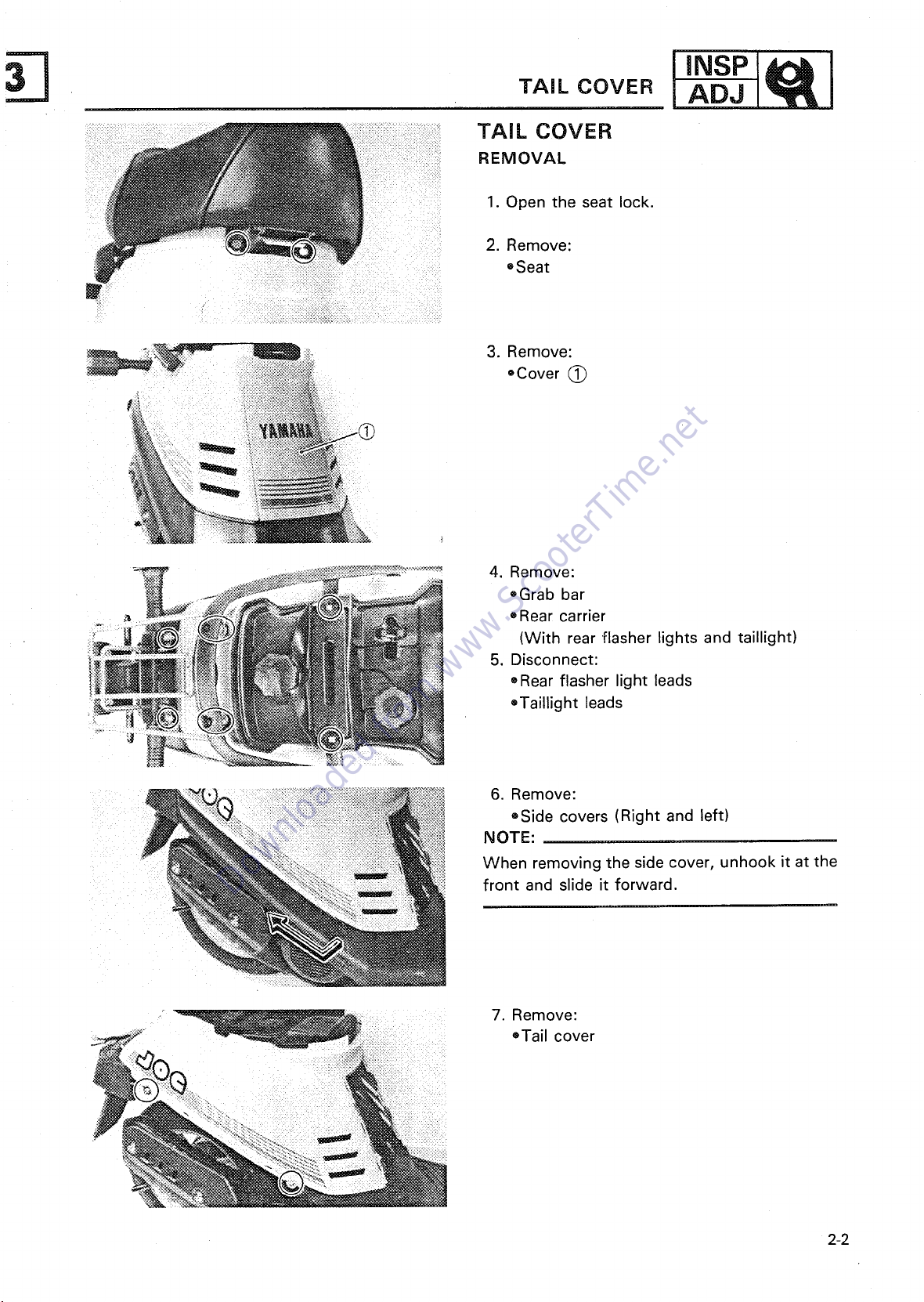
TAIL COVER
REMOVAL
1. Open the seat lock.
2. Remove:
=Seat
3. Remove:
-Cover (_
4. Remove:
,Grab bar
_ , Rear carrier
(With rear flasher lights and taillight)
5. Disconnect:
,Rear flasher light leads
•Taillight leads
6. Remove:
®Side covers (Right and left)
NOTE:
When removing the side cover, unhook it at the
front and slide it forward.
7. Remove:
=Tail cover
: !!
2-2
Page 20
INSP E
Downloaded from www.ScooterTime.net
ADJ _1 TA'LCOVER
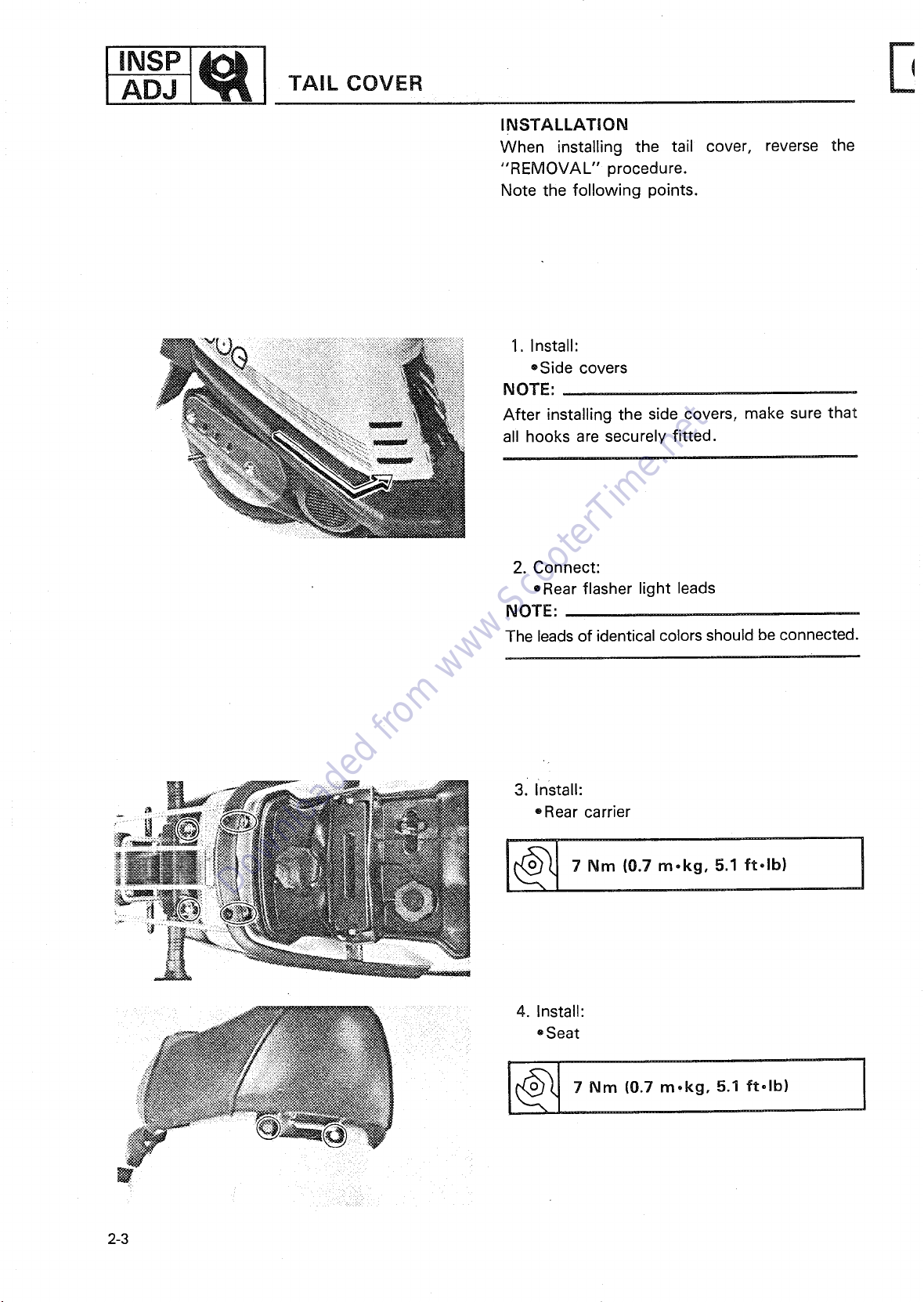
INSTALLATION
When installing the tail cover, reverse the
"REMOVAL" procedure.
Note the following points.
1. Install:
®Side covers
NOTE:
After installing the side covers, make sure that
all hooks are securely fitted.
2. Connect:
eRear flasher light leads
NOTE:
The leadsof identical colors should beconnected.
31install:
i_J_. ®Rear carrier
i__i 7Nm (0.7 m,kg, 5.1 ft-lb)
4. Install:
eSeat
!_ 7 Nm (0.7 5.1 ft,lb)
2-3
m,kg,
Page 21
I FRONT FENDER, FRONT PANEL INSP
Downloaded from www.ScooterTime.net
- i
AND FOOTREST BOARD ADJ
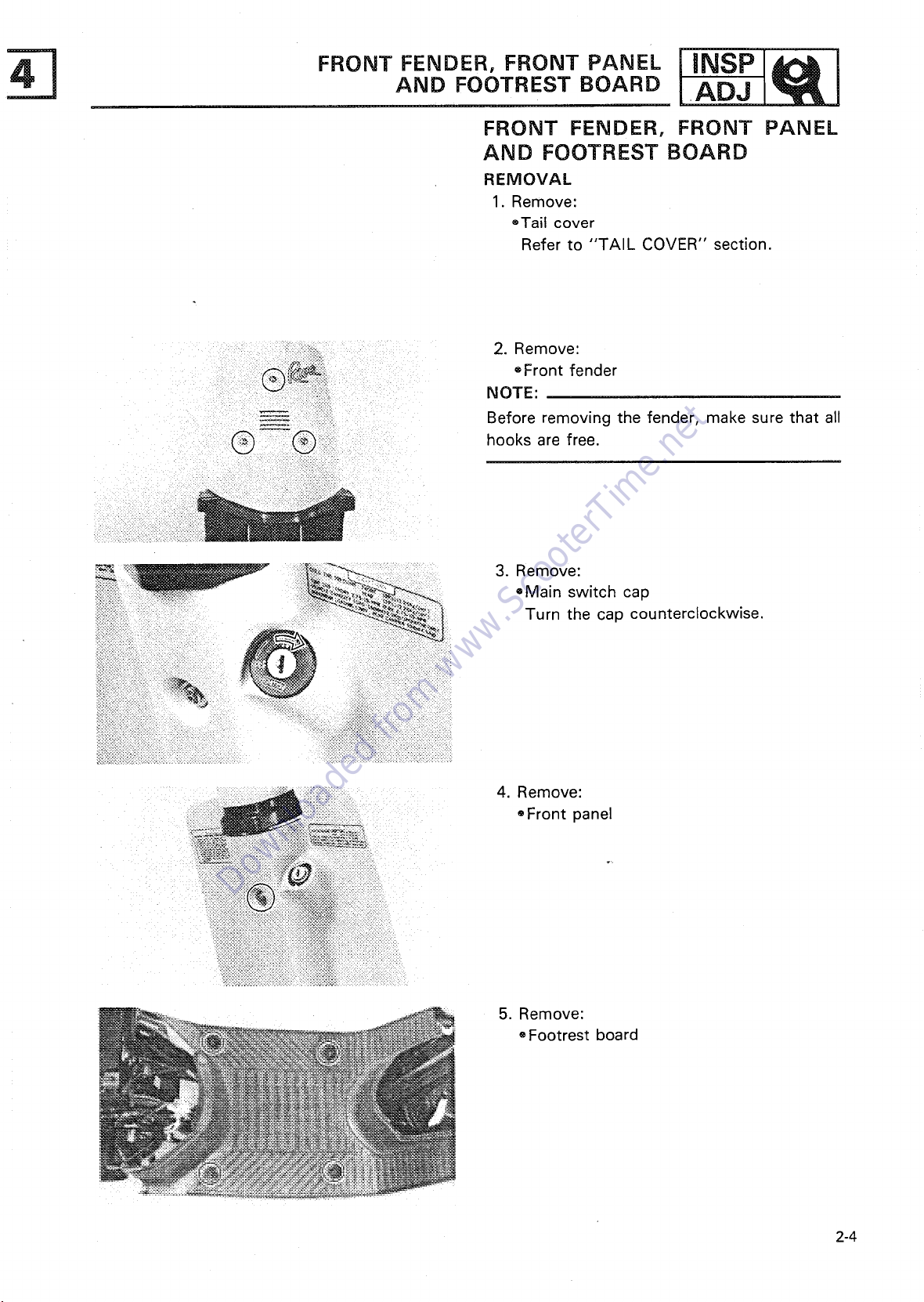
FRONT FENDER, FRONT PANEL AND FOOTREST BOARD
REMOVAL
1. Remove:
-Tail cover
Refer to "TAIL COVER" section.
2. Remove:
®Front fender
_, NOTE:
@ i:Q::!i hooks are free.
_N % - -_ - 3. Remove:
_iiiii:iiii___" ,Main switch cap
i:iiii!i!ilii_ii Turn the cap counterclockwise.
!_-::
Before removing the fender, make sure that all
4. Remove:
®Front panel
5. Remove:
, Footrest board
2-4
Page 22
I INSP
Downloaded from www.ScooterTime.net
FRONT FENDER, FRONT PANEL
AND FOOTREST BOARD/HANDLEBAR COVERS
I
NSTALLATION
Reverse the "REMOVAL" procedure.
Note the following points,
1. Install:
® Front fender
NOTE:
After installing the front fender, make sure that
all hooks are securely fitted.
E
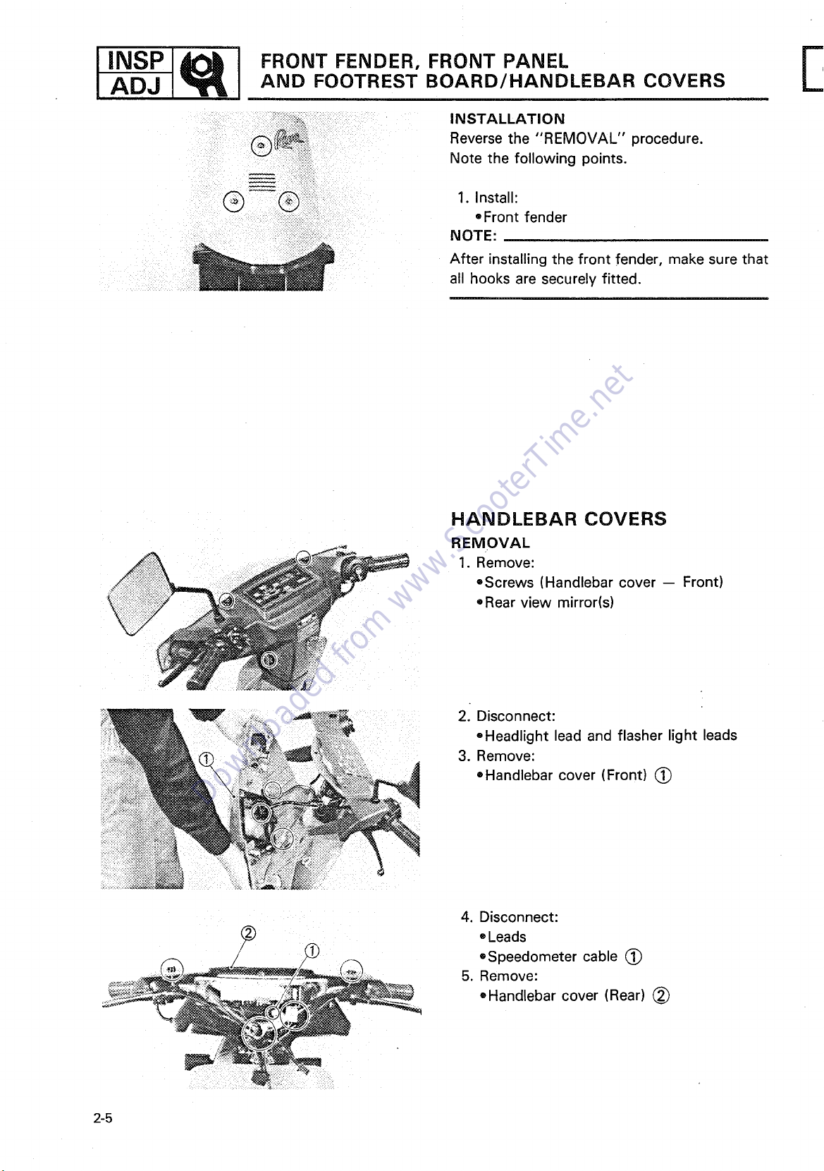
HANDLEBAR COVERS
REMOVAL
1. Remove:
=Screws (Handlebar cover -- Front)
=Rear view mirror(s)
2. Disconnect:
-Headlight lead and flasher light leads
3. Remove:
-Handlebar cover (Front) (~
4. Disconnect:
® Leads
-Speedometer cable (~
5. Remove:
®Handlebar cover (Rear) (~
2-5
Page 23

ENGINE iDLE SPEED ADJUSTMENT I ADJ
Downloaded from www.ScooterTime.net
INSTALLATION
1. Install:
oHandlebar cover (Rear) (~)
2. Connect:
• Leads
oSpeedometer cable (~)
NOTE:
Position the cables as shown.
Front brake cable
(~) Throttle cable
(~) Rear brake cable
I
3. Connect:
eHeadlight lead and flasher ]~ght leads
4. Install:
® Handlebar cover (Front)
®Rear view mirror(s)
ENGINE
ENGINE iDLE SPEED ADJUSTMENT
1. Remove:
• Tail cover,.
Refer to "TAIL COVER" section.
2. Start the engine and warm it up before check-
ing the idle speed.
NOTE:
A warm engine is defined as one which had been
operated for about 3 minutes at 3,000 r/min with
no load.
2-6
Page 24
I INSP
Downloaded from www.ScooterTime.net
ENGINE IDLE SPEED ADJUSTMENT/
THROTTLE CABLE FREE PLAY ADJUSTMENT
3. Attach:
®Inductive Tachometer (YU-08036)
4. Check:
eEngine idle speed
Out of specification-*Adjust.
Engine Idle Speed:
1,500-2,100 r/rnin
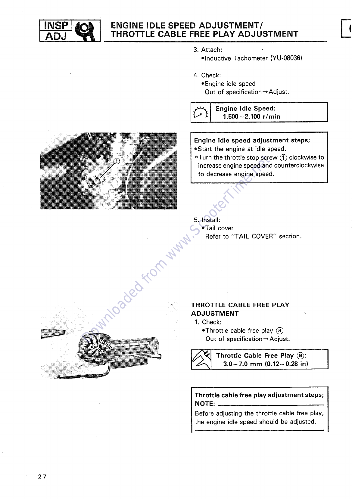
Engine idle speed adjustment steps;
®Start the engine at idle speed.
eTurn the throttle stop screw (~ clockwise to
increase engine speed and counterclockwise
to decrease engine speed.
E
5. Install:
eTail cover
Refer to "TAIL COVER" section.
THROTTLE CABLE FREE PLAY
ADJUSTMENT
1. Check:
*Throttle cable free play (~
Out of specification-*Adjust.
[~ Throttle Cable Free Play (~):
3.0-7.0 mm (0.12-0.28 in)
Throttle cable free play adjustment steps;
NOTE:
Before adjusting the throttle cable free play,
the engine idle speed should be adjusted.
2-7
Page 25
AUTOLUBE PUMP CABLE ADJUSTMENT ADJ
Downloaded from www.ScooterTime.net
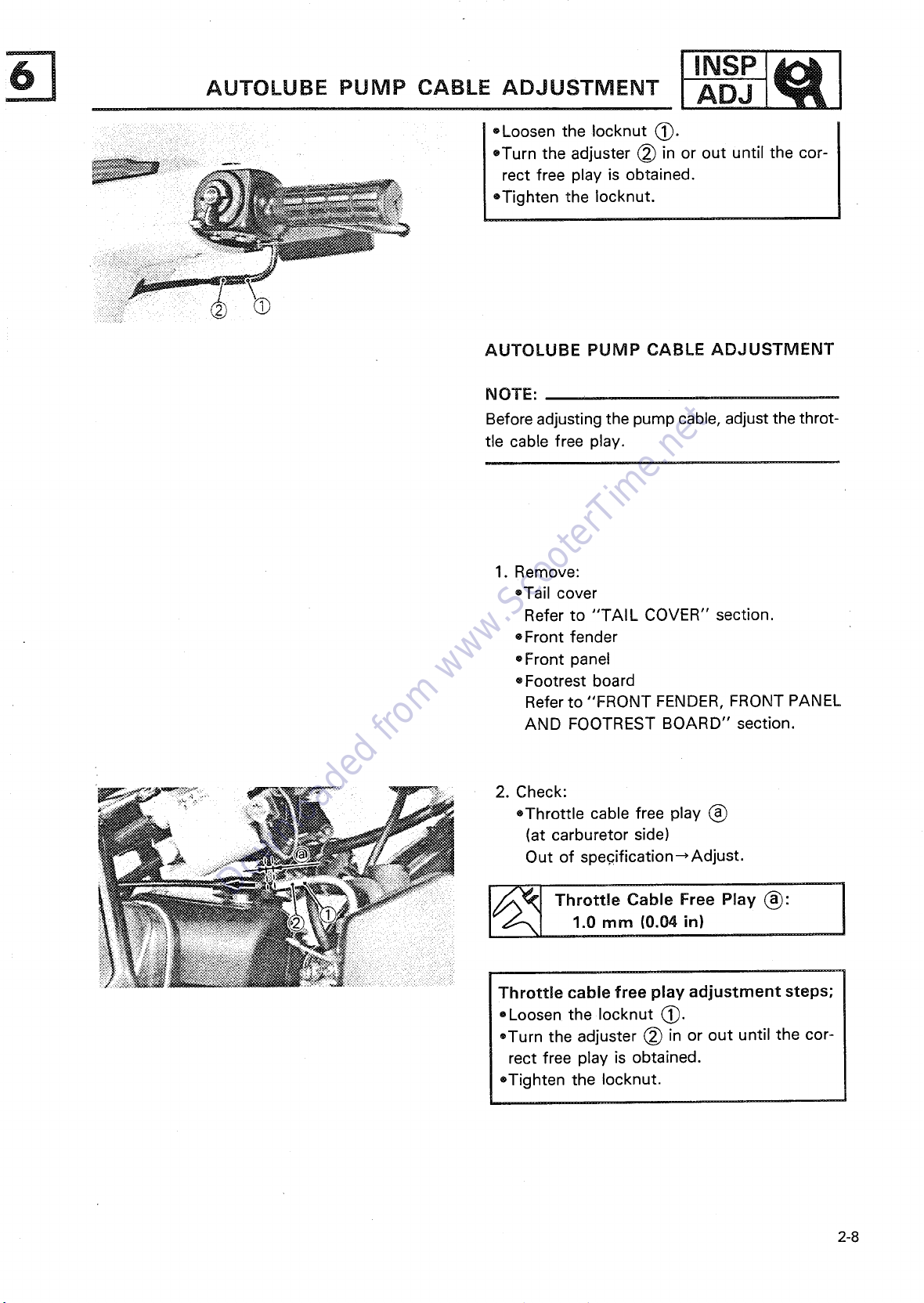
=Loosen the Iocknut (_.
oTurn the adjuster (_ in or out until the cor-
!_:__...... rect free play is obtained.
=Tighten the Iocknut.
AUTOLUBE PUMP CABLE ADJUSTMENT
NOTE:
Beforeadjustingthe pumpcable, adjustthe throt-
tle cable free play.
1. Remove:
=Tail cover
Refer to "TAIL COVER" section.
* Front fender
=Front panel
eFootrest board
Refer to "FRONT FENDER, FRONT PANEL
AND FOOTREST BOARD" section.
2. Check:
*Throttle cable free play (_
(at carburetor side)
Out of specification_Adjust.
..... 1.0 mm (0.04 in)
J_ Thrott,eCableFreePlay(_):
Throttle cable free play adjustment steps;
=Loosen the Iocknut (_.
=Turn the adjuster _ in or out until the cor-
rect free play is obtained.
=Tighten the Iocknut.
2-8
Page 26
4. Close the throttle grip completely.
Downloaded from www.ScooterTime.net
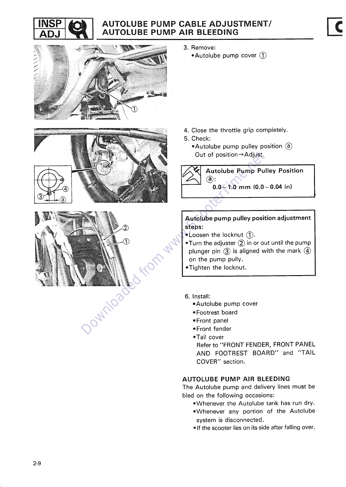
5. Check:
®Autolube pump pulley position (_
Out of position-*Adjust.
®:
0.0-1.0 mm (0.0-0.04 in)
_ Autolube Pump Pulley Position
Autolube pump pulley position adjustment
steps:
oLoosen the Iocknut _.
®Turnthe adjuster (_ in or out until the pump
plunger pin (_ is aligned with the mark _)
on the pump pully.
eTighten the Iocknut.
6. Install:
oAutolube pump cover
oFootrest board
®Front panel
• Front fender
eTail cover
Refer to "FRONT FENDER, FRONT PANEL
AND FOOTREST BOARD" and "TAIL
COVER" section.
AUTOLUBE PUMP AIR BLEEDING
The Autolube pump and delivery lines must be
bled on the following occasions:
•,Whenever the Autolube tank has run dry.
oWhenever any portion of the Autolube
system is disconnected.
oIf the scooter lieson its sideafter falling over.
2-9
Page 27
__ AUTOLUBE PUMP AIR BLEEDING ADJ
Downloaded from www.ScooterTime.net
1. Remove:
=Tail cover
®Front fender
-Front panel
• Footrest board
Refer to "TAIL COVER" and "FRONT
FENDER, FRONT PANELAND FOOTREST
BOARD" section.
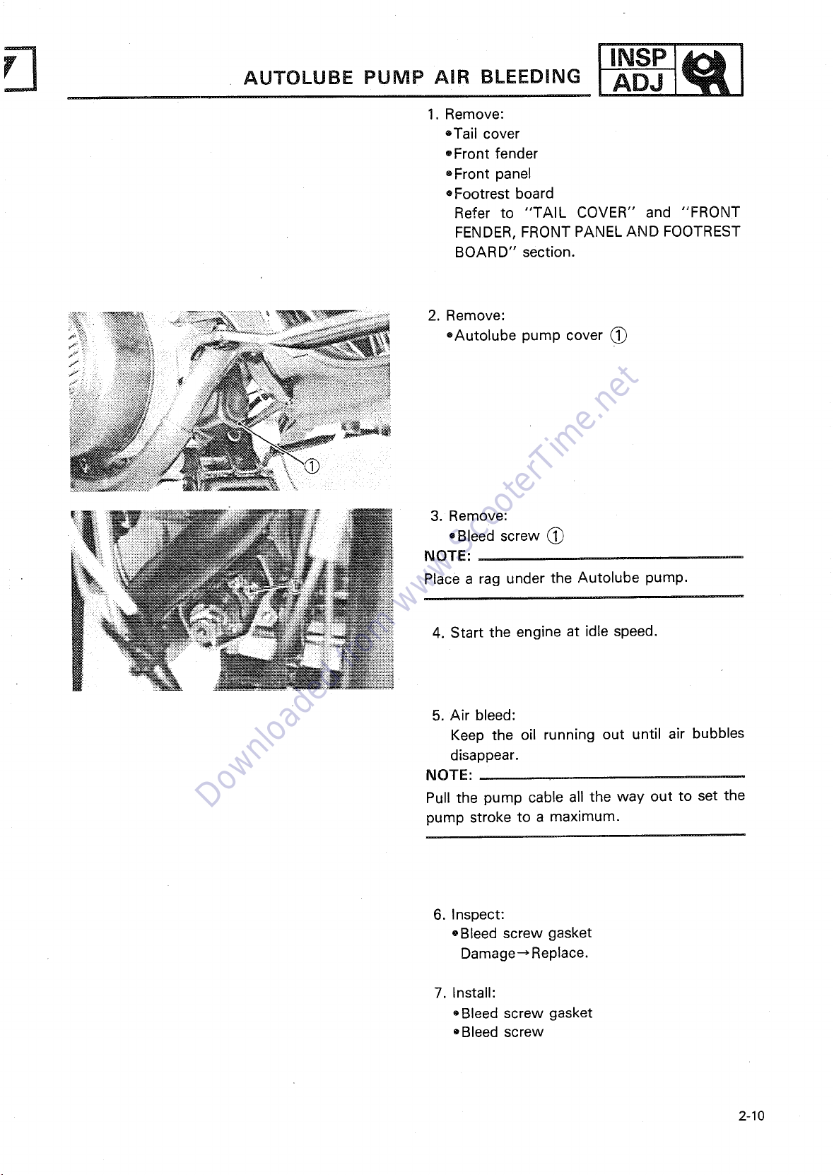
2. Remove:
®Autolube pump cover
J
I,.sPl l
3. Remove:
• Bleed screw @
NOTE:
Place a rag under the Autolube pump.
4. Start the engine at idle speed.
5. Air bleed:
Keep the oil running out until air bubbles
disappear.
NOTE:
Pull the pump cable all the way out to set the
pump stroke to a maximum.
6. Inspect:
®Bleed screw gasket
Damage_Replace.
7. Install:
•,Bleed screw gasket
• Bleed screw
2-10
Page 28
ADJ AiR CLEANER ELEMENT CLEANING
Downloaded from www.ScooterTime.net
t INSP AUTOLUBE PUMP AiR BLEEDING/
8. Keep the enginerunningat about2,000 r/min
for two minutes or so, and both distributor
and delivery pipe can be completely bled.
NOTE:
It is difficult to bleed the distributor completely
with the pump strokeat aminimum, and therefore
the pump stroke should be set to a maximum.
9. Install:
eAutolube pump cover
• Footrest board
®Front panel
Front fender
oTail cover
Refer to "FRONT PANEL, FRONT FENDER
ANT FOOTREST BOARD" and "TAIL
COVER" section.
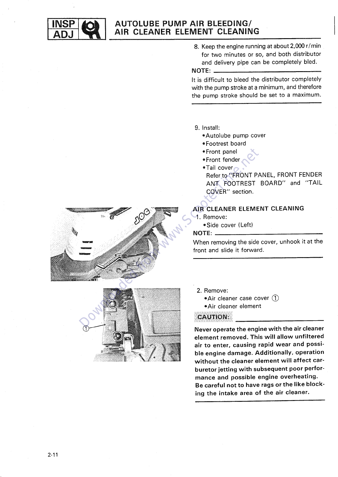
AIR CLEANER ELEMENT CLEANING
1. Remove:
®Side cover (Left)
;_ NOTE:
When removing the side cover, unhook it at the
front and slide it forward.
2. Remove:
®Air cleaner case cover (_
eAir cleaner element
i i : i_iii i:i i_i!i !_i!i i_ ! i
Never operate the engine with the air cleaner
element removed. This will allow unfiltered
air to enter, causing rapid wear and possi-
ble engine damage. Additionally, operation
without the cleaner element will affect car-
buretor jetting with subsequent poor perfor-
mance and possible engine overheating.
Be careful not to have rags or the like block-
ing the intake area of the air cleaner.
2-11
Page 29
;'='8 I AiR CLEANER ELEMENT CLEANHNG/ INSP
Downloaded from www.ScooterTime.net
FUEL COCK CLEANING ADJ
3. Clean:
oAir cleaner element
Air cleaner element cleaning steps:
oWash the element gently, but thoroughly in
solvent.
Never use low flash point solvents such as
gasoline to clean the element. Such sol-
vent may lead to a fire or explosion.
oSqueezethe excess solvent out of the element
and let dry.
:::::::::::::::::::::::::::::::::::::::::::::::::::::::::::::::::::::::::::::::::::::::::
Do not twist the element when squeezing
the element.
4. Inspect:
oElement
Damage-_ Replace.
5. Apply:
oFoam-air-filter oil or SAE 10W30 type SE
motor oil
Onto the element.
6. Squeeze out the excess oil.
NOTE:
The element should be wet but not dripping.
7. Install:
oAir cleaner element
®Air cleaner case cover
®Side coyer (Left)
FUEL COCK CLEANING
1. Remove:
-Tail cover
Refer to "TAIL COVER" section.
2-12
Page 30
ADJ FUEL COCK CLEANHNG
Downloaded from www.ScooterTime.net
I,NsP E
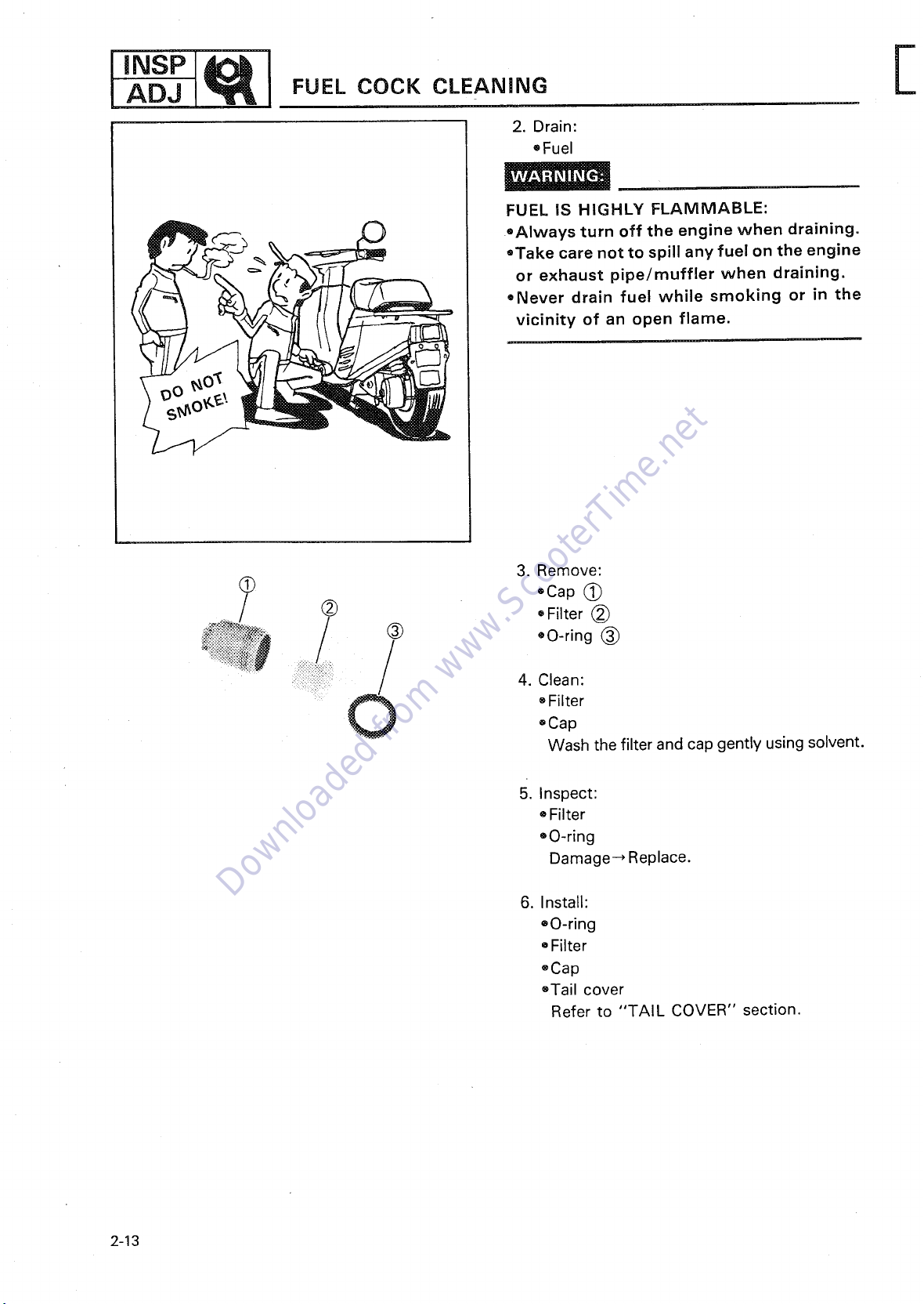
2. Drain:
=Fuel
FUEL IS HIGHLY FLAMMABLE:
__ _k,_ ®Always turn off the engine when draining.
==_£ or exhaust pipe/muffler when draining.
' =_ { " oNever drain fuel while smoking or in the
(_ *Cap (_
_,_/ (_) ®Filter (_
_*_'!_ii!_iiii_ _:::_ 4. Clean:
=Take care not to spill any fuel on the engine
vicinity of an open flame.
3. Remove:
Filter
oCap
Wash the filter and cap gently using solvent.
2-13
5. Inspect:
• Filter
oO-ring
Damage--* Replace.
6. Install:
®O-ring
Filter
oCap
oTail cover
Refer to "TAIL COVER" section.
Page 31

COMPRESSION PRESSURE MEASUREMENT ADJ
Downloaded from www.ScooterTime.net
• ;!i...... COMPRESSION PRESSURE
Insufficient compression pressure will result in
performance loss and may indicate worn or
__4 A damaged piston rings.
1. Remove:
®Cover (_
2. Warm up engine for serveral minutes, then
stop the engine.
........_ 3. Remove:
I eSpark plugs
4. Connect:
®Compression Gauge (YU-33223) (_
INSP
_ "" ::::::::........ • Compression
_..._:_::,. 5. Measure:
NOTE:
Start the starter motor and throttle valve wide-
open until the pressure indicated on gauge can
riseno further. Compression should be within the
specified levels.
Compression Pressure (at sea level):
Standard ....... 800 kPa (8.0 kg/cm 2,
Minimum ...... 640 kPa (6.4 kg/cm 2,
When cranking engine, ground spark plug
wires to prevent sparking.
Compression test steps (below minimum
levels):
oSquirt a few drops of oil into cylinder.
eMeasure compression again.
114 psi)
91 psi)
Reading Diagnosis
Higher than piston and piston
without oil
Same as ring(s), valve(s) and
without oil
Compression test steps (above standard
levels):
eCheck cylinder head or piston crown for car-
bon deposits.
®Worn cylinder,
rings
®Defective piston,
cylinder head gasket
2-14
Page 32

IiNSPADJ J_l ENGINE OIL LEVEL INSPECTION
Downloaded from www.ScooterTime.net
ENGINE OiL LEVEL INSPECTION
1. Place the scooter on the level place.
NOTE:
Be sure the scooter is positioned stratight up and
on both wheels when inspecting the oil level,
":":%_{iii_ 2. Inspect:
...... ":<_ oEngine oil level
__:_-_ .... "............- 0il level low-,Add sufficient oil by the
" _ following inspection steps.
(_) "OIL" indicator light
_3N _0-_ _$E ONLY
Engine oil level visual inspection steps:
position.
ITurn main switch to "_" I
l
does not :ome on. comes on.
I "OlL"indicatorlight I I "OlL"indicatorlight I
+
"ON" position.
I urn main switch to
I
"OIL" indicator light _ i"OIL" indicator light I
does not come on. ?1 iomeson i
e,ec-1en0ineo"'eve'"e'ec-I Su 0'eat'he°"'lI trical circuit, trical circuit are OK.
I
2-15
Page 33

ENGINE OiL LEVEL iNSPECTiON/ l lNSPI_I_ ITRANSMISSION OiL REPLACEMENT ADJ
Downloaded from www.ScooterTime.net
_ Recommended Oil:
NOTE:
Install the oil tank filler cap (_ and push it fully
into the filler.
Always use the same type of engine oil; mix-
ing oils may result in a h_rmful chemical
reaction and lead to poor performance.
Yamalube 2 or Air Cooled 2
Stroke Engine Oil
Oil Capacity:
Total:
0.8 L (0.7 Imp qt, 0.84 US qt)
TRANSMISSION OIL REPLACEMENT
1. Warm up the engine at idle speed, then stop
it.
2. Place the oil pan under the drain hole.
3. Remove:
oDrain bolt (_
Drain the transmission oil.
oOil filler plug
2-16
Page 34

ADJ FUEL LiNE iNSPECTiON
Downloaded from www.ScooterTime.net
t INSPt_ I TRANSMISSION OIL REPLACEMENT/
4. Inspect:
®Gasket (Drain bolt)
• O-ring (Oil filler plug)
Damage_ Replace.
5. Install:
• Gasket
Drain bolt
I_ Drain Bolt:
6. Fill:
•Transmission case
___ Transmission Oil:
NOTE:
Wipe off any oil split on the crankcase, tire or
wheel.
7. Install:
•Oil filler plug
18 Nm (1.8 m.kg, 13 ft.lb)
Yamalube 4 or SAE 10W30 Type
SE Motor Oil
Capacity:
0.1 L (0.09 Imp qt, 0.11 US qt)
FUEL LINE INSPECTION
1. Remove:
eTail cover
Refer to "TAIL COVER" section.
2-17
Page 35

REAR BRAKE LEVER FREE PLAY CHECK ADJ
Downloaded from www.ScooterTime.net
F.ONTB LEVE.F.EEP.AC.ECK/I,.SP[ I
_ 2. Inspect:
oFuel pipe (_
Cracks/Damage -_Replace.
3. Install:
oTail cover
Refer to "TAIL COVER" section.
FRONT BRAKE LEVER FREE PLAY CHECK
1. Check:
oFront brake lever free play
CHASSIS
Out of specification-_Adjust.
,0- 0 l
Front brake lever free p|a¥ adjustment
steps:
oTurn the adjuster (_ in or out until the cor-
rect free play is obtained.
REAR BRAKE LEVER FREE PLAY CHECK
1. Check:
®Rear brake lever free play (_
Out of sP,ecification_ Adjust.
'_ 10-20 mm (0.4-0.8 in)
Rear brake lever free play adjustment
steps;
®Turnthe adjuster (_ in or out until the cor-
rect free play is obtained.
2-18
Page 36

ADJ TIRE AND WHEEL iNSPECTION
Downloaded from www.ScooterTime.net
I INSP I (i_ FRONT AND REAR BRAKE LNNING INSPECTION/ l
[] _. FRONT AND REAR BRAKE LINING
) 1. Activate the brake lever.
2. Inspect:
-_; ®Wear indicator (_
Indicator at wear limit line (_Replace
brake shoes.
!
_; TiRE AND WHEEL INSPECTION
1. Measure:
®Air pressure
Out of specification-_Adjust.
Cold tire
Front 125 kPa (1.25 kg/crn 2, 18 psi)
Rear 225 kPa (2.25 kg/crn 2, 32 psi)
Proper loading of your scooter is important
for the handling, braking, and other perfor-
mance and safety characteristics of your
scooter. Do not carry loosely packed items
that can shift. Securely pack your heaviest
items close to the center of the scooter, and
destribute the weight evenly from side to
side. And check the condition and pressure
of your tires. NEVER OVERLOAD YOUR
SCOOTER. Make sure the total weight to the
cargo, rider, passenger, and accessories (fair-
ing, saddlebags, etc. if approved for this
model) does not exceed the maximum load
of the scooter. Operation of an overloaded
scooter could cause tire damage, an acci-
dent, or even injury.
pressure
2-19
Page 37

" STEERING ADJUSTMENT ADJ
Downloaded from www.ScooterTime.net
2. Inspect:
'_._=q _ oTire surface
__, _:._\1 Wear/Damage/Cracks/Road hazards--*
"-" +Aluminum wheels
Damage/Bends--* Replace.
Never attempt even small repairs to the
wheel.
__._ ii. Replace.
Ride conservatively after installing a tire to
allow it to seat itself properly on the rim.
(]_) 3. Measure:
(_ _ Minimum Tire Tread Depth:
®Tire tread depth
Out of specification_Replace.
(front and rear)
0.8 mm (0.03 in)
(_) Tread depth
Wear indicator
Side wall
STEERING ADJUSTMENT
1. Place the scooter on its centerstand, then
elevate the front wheel.
2-20
Page 38

INSP
Downloaded from www.ScooterTime.net
STEERING ADJUSTMENT/BATTERY
2. Check:
=Steering assembly bearings
Grasp the bottom of the forks and gently
rock the rock assembly back and forth.
Looseness-*Adjust.
Steering head adjustment steps:
=Remove the front fender and front panel.
Refer to "FRONT FENDER, FRONT PANEL
AND FOOTREST BOARD" section.
=Tighten the ring nut ~ to specification us-
ing the Ring Nut Wrench (YU-33975).
Ring Nut (~:
30 Nm (3.0 m okg, 22 ftolb)
NOTE:
Set the torque wrench to the ring nut wrench
so that they form right angle.
*Move the handlebar up and down, and/or
back and forth. If handlebar free play is ex-
cess, tighten the bolt (~ to specification.
Bolt (~:
60 Nm (6.0 m-kg, 43 ft-lb)
=Install the front fender and front panel.
ELECTRICAL
BATTERY
1. Check:
= Fluid level
Incorrect-* Refill.
Fluid level should be between upper and
lower level marks.
(~ Upper level
(~) Lower level
iiii!!ii i ii i iiiii!iii!!i
Refill with distilled water only; tap water
contains minerals harmful to a battery.
2-21
Page 39

BATTER*L'NSP1 IAOJ
Downloaded from www.ScooterTime.net
2. inspect:
• Breather hose
Obstruction_ Remove.
Damage-* Replace.
3. Inspect:
®Battery
Replace the battery if:
Battery voltage will not riseto a specific value
or bubbles fail to rise even after many hours
of charging.
®Sulfation of one or more cells occurs, as in-
dicated by the plates turning white, or an ac-
cumulation of material exists in the bottom
of the cell.
®Specific gravity readings after a long, slow
charge indicate one cell to be lower than the
rest.
®Warpage or buckling of plates or insulators
• is evident.
®Specific gravity:
Less than 1.280-*Recharge battery.
Charging Current:
_ 4. Measure:
0.4 amps/10 hrs
Specific Gravity:
1.280 at 20°C (68°F)
2-22
Page 40

I INSP
Downloaded from www.ScooterTime.net
ADJ l( l BATTERY/FUSE INSPECTION
Always charge a new battery before using
it to ensure maximum performance.
Battery electrolyte is dangerous; it contains
sulfuric acid and therefore is poisonous and
highly caustic.
__,=== Always follow these preventive measures:
_\_J--_ 9/ -SKIN-- Flush with water.
____= '_ "_ can cause servere burns or permanent eye
oAvoid bodily contact with electrolyte as it
injury.
=Wear protective eye gear when handling or
working near batteries.
Antidote (EXTERNAL):
®EYES--Flush with water for 15 minutes and
get immediate medical attention.
Antidote (INTERNAL):
eDrink large quantities of water or milk
follow with milk of magnesia) beaten egg,
or vegetable oil. Get immediate medical
attention.
Batteries also generate explosive hydrogen
gas, therefore you should always follow
these preventive measures:
eCharge batteries in a well-ventilated area.
®Keep batteries away from fire, sparks, or
open flames (e.g., welding equipment,
lighted cigarettes, etc.)
=DO NOT SMOKE when charging or handl-
ing batteries.
KEEP BATTERIES AND ELECTROLYTE OUT
OF REACH OF CHILDREN.
FUSE INSPECTION
1. Open the seat lock.
2-23
Page 41

FUSE iNSPECTION/SPARK PLUG iNSPECTiON ADJ
Downloaded from www.ScooterTime.net
2. Inspect:
eFuse C)
Defective--* Replace.
Blown fuse procedure steps:
=Turn off ignition and the circuit.
=Install a new fuse of proper amperage.
=Turn on switches to verify operation of elec-
trical device.
®If fuse blowsimmediately again, check circuit
in question.
Do not use fuses of higher amperage rating
than recommended. Extensive electrical
system damage and fire could result from
substitution of a fuse of impcoper amperage:
i =Cover @
_i_:_- =Spark plug,
0 H_
" --?: i
Description Amperage Quantity
Main 7A 1
SPARK PLUG INSPECTION
1. Remove:
2. Inspect:
=Electrode _)
Wear/Damage--, Replace.
=Insulator (_
Abnormal Color_ Replace.
@ @ Standard Spark Plug:
"
BPR6HS (N.G.K.)
2-24
Page 42

I INSP
Downloaded from www.ScooterTime.net
SPARK PLUG INSPECTION/
HEADLIGHT BEAM ADJUSTMENT/IGNITION TIMING
3. Measure:
ePlug gap (~
Out of specification--* Regap.
Use a Wire Gauge or Feeler Gauge.
I~ Spark Plug Gap (~: ]
0.9-1.0 mm (0.035-0.039 in)
4. Clean the plug with a spark plug cleaner if
necessary.
5. Tighten:
Before installing a spark plug, clean the gasket
and plug surfaces.
NOTE:
Finger,tighten the spark plug before torquing to
specification.
Spark Plug:
20 Nm (2.0 m-kg, 14 ft.ib)
HEADLIGHT BEAM ADJUSTMENT
1. Adjust:
• Headlight (Vertically)
Vertical adjustment
Higher Loosen the adjusters (~)
Lower Tighten the adjusters (~)
• Headlight (Horizontal)
Horizontal adjustment
Right the adjuster (~)
Left
Loosen the adjuster (~) or tighten
Loosen the adjuster (~) or tighten
the adjuster (~)
IGNITION TIMING
Adjustment free.
2-25
Page 43

Downloaded from www.ScooterTime.net
Page 44

CHAPTER 3
Downloaded from www.ScooterTime.net
ENGINE OVERHAUL
I ENG
ri
ENGINE REMOVAL .
PREPARATION FOR REMOVAL ................................. D-3
TAIL COVER .................................................. D-3
FRONT FENDER, FRONT PANEL AND FOOTREST BOARD ........ D-3
CARBURETOR ................................................. D-3
CABLES, LEADS AND PIPES ................................... D-4
ENGINE REMOVAL ............................................. D-4
DISASSEMBLY
MUFFLER ..................................................... D-5
CYLINDER HEAD .............................................. D-5
CYLINDER .................................................... D-6
PISTON PIN AND PISTON ...................................... D-6
PRIMARY AND SECONDARY SHEAVE ........................... D-6
STARTER SYSTEM ............................................ D-7
C.D.I. MAGNETO .............................................. D-8
AUTOLUBE PUMP ............................................. D-8
TRANSMISSION ............................................... D-8
CRANKCASE AND CRANKSHAFT ............................... D-9
INSPECTION AND REPAIR ....................................... D-10
CYLINDER HEAD .............................................. D-10
CYLINDER AND PISTON ....................................... D-10
PISTON PIN AND PISTON PIN BEARING ........................ D-12
AUTOLUBE PUMP ............................................. D-12
CRANKSHAFT ................................................. D-12
TRANSMISSION ............................................... D-13
PRIMARY SHEAVE ................... ~ ......................... D-13
SECONDARY SHEAVE ......................................... D-13
V-BELT ....................................................... D-15
STARTER CLUTCH AND GEARS ................................ D-15
............................................. D-3
.................................................. D-5
ENGINE ASSEMBLY AND ADJUSTMENT
CRANKSHAFT AND CRANKCASE ............................... D-16
TRANSMISSION ............................................... E-1
AUTOLUBE PUMP ............................................. E-3
C.D.I. MAGNETO .............................................. E-4
STARTER SYSTEM ............................................ E-5
PRIMARY AND SECONDARY SHEAVE ........................... E-6
PISTON PIN AND PISTON ...................................... E-8
CYLINDER AND CYLINDER HEAD ............................... E-9
MUFFLER ..................................................... E-10
REMOUNTING ENGINE ......................................... E-10
......................... D-16
Page 45

Downloaded from www.ScooterTime.net
Page 46

ENG %-j]
Downloaded from www.ScooterTime.net
ENGINE REMOVAL
ENGINE OVERHAUL
ENGINE REMOVAL
NOTE:
It is necessary to remove the engine in order to
remove the following components.
oCylinder head
• Cylinder
• Piston
®CDI magneto
®Starter motor
®Primary and secondary sheave
PREPARATION FOR REMOVAL
1. Remove all dirt, mud, dust and foreign
material before removal and disassembly.
2. Use proper tools and cleaning equipment.
Refer to "CHAPTER 1. GENERAL INFOR-
MATION-SPECIAL TOOLS" section.
NOTE:
When disassembling the engine, keep mated parts
together. This includes gears, cylinder, piston and
other parts that have been " mated" through nor-
mal wear. Mated parts must be reused as an
assembly or replaced.
3-1
Page 47

ENGINE REMOVAL
Downloaded from www.ScooterTime.net
.
During engine disassembly, clean all parts and
place them in trays in the order of
disassembly. This will speed up assembly time
and help assure that all parts are correctly
reinstalled in the engine.
.
Drain the transmission oil completely.
Refer to "CHAPTER 2.--TRANSMISSION
OIL REPLACEMENT" section.
I E.o I, .l
TAIL COVER
1. Remove:
.Seat
• Tail cover
• Rear carrier
Refer to "CHAPTER 2.--TAIL COVER"
section.
FRONT FENDER, FRONT PANEL AND FOOTREST BOARD
1. Remove:
® Front fender
® Front panel
= Footrest board
Refer to "CHAPTER 2.--FRONT FENDER,
FRONT PANEL AND FOOTREST BOARD"
section.
CARBURETOR
1. Remove:
-Air cleaner case
3-2
Page 48

[ENO EOO,NE.EMOVA, Fi
Downloaded from www.ScooterTime.net
2. Remove:
oFuel pipe (_
oOil delivery pipe (_)
®Vacuum pipe (_)
®Auto choke unit lead
3. Remove:
_, ®Carburetor top cover
oCarburetor
NOTE:
Cover the carburetor with a clean rag to prevent
dirt or foreign matter into the carburetor.
i 1. Remove:
_i CABLES, LEADS AND PIPES
i
-Autolube pump cover @
2. Remove:
oOil pump cable (_
oOil pipe (_)
NOTE:
Plug the oil pipe so the oil will not run out of the
oil tank.
3. Remove:
• Battery negative lead (_
3-3
Page 49

4 ENGINE REMOVAL ENG %_
Downloaded from www.ScooterTime.net
4. Remove:
®Spark plug cap
5. Remove:
.Earth lead (_
]
6. Remove:
• Rear brake cable (_
7. Disconnect:
• C.D.I. magneto leads
• Starter motor leads
+,
ENGINE REMOVAL
1. Remove:
• Air shroud (_
3-4
Page 50

[ENG ENGINEREMOVAL/DISASSEMBLY
Downloaded from www.ScooterTime.net
2. Remove:
oEngine mounting bolts
3. Remove:
®Engine
Lift up the frame and remove the engine.
4. Place the frame on a suitable stand.
DISASSEMBLY
MUFFLER
1. Remove:
oExhaust pipe
3-5
Page 51

O'SASSEMB'IEN°
Downloaded from www.ScooterTime.net
2. Remove:
`"Muffler
CYLINDER HEAD
1. Remove:
`"Fan cover
2. Remove:
" _::_:_ ®Air shroud
3. Remove:
(_,
........::: : _ ,,Cylinder head (_
®Cylinder head gasket
NOTE:
`"Before loosening the cylinder head, loosen the
spark plug _).
• The cylinder head holding nuts should beloosen-
ed 1/2 turn each time, and remove.
3-6
Page 52

O,SASSEMBL* E
Downloaded from www.ScooterTime.net
CYLINDER
1. Remove:
• Cylinder (_
i_ • Cylinder gasket
2. Remove:
®Carburetor joint (_
oReed valve assembly
PISTON PIN AND PISTON
1. Remove:
®Piston pin clip (_
NOTE:
Before removing the piston pin clip, cover the
crankcase with a cleanrag so you will not acciden-
tally drop the clip into the crankcase.
2. Remove:
oPiston pin (_
®Piston (_)
®Piston pin bearing
NOTE:
Before removing the piston pin, deburr the clip
groove and pin hole area. If the piston pin groove
is deburred and piston pin is still difficult to
remove, use Piston Pin Puller (YU-01304).
Do not use a hammer to drive the piston pin
out.
3-7
Page 53

PRIMARY AND SECONDARY SHEAVE
Downloaded from www.ScooterTime.net
1. Remove:
*Crankcase cover (Left)
*Dowel pins
2. Remove:
*Fan (_
;i4_! '- __ 3. Remove:
*Nut @ (Primary sheave)
NOTE:
--...... the C.D.I. magneto using Flywheel Holding Tool
_ (YU-01235). •
- *Conical spring washer (_
_._,. *Primary fixed sheave _)
"_'_, ,,V-Belt
When loosening the nut (primary sheave), hold
4. Remove:
*One-way clutch (_
3-8
Page 54

_ !_:._ STARTER SYSTEM
Downloaded from www.ScooterTime.net
/ ';_-_-:_ ........ 1 Remove:
3-9
• Starter clutch assembly (_
2. Remove:
-Plate (_ (Idle gear)
Page 55

q
Downloaded from www.ScooterTime.net
O,SASSEMB. ! I' .1
j ii
.Z ; !;;~!!
3. Remove:
eStarter wheel gear (~)
® Bearing (~
®Washers (~
oldie gear (~)
4. Remove:
®Stay (~
oCollar (~)
5. Remove:
oStarter motor (~
6. Remove:
®Kick crank (~
7. Remove:
oKick torsion spring (~
3-10
Page 56

9. Remove:
Downloaded from www.ScooterTime.net
oCirclip (_
oPlain washer (_
C.D.I. MAGNETO
1. Remove:
...._ oNut (_ (C.D.I. magneto)
Use Flywheel Holding Tool (YU-01235) (_).
._ ii;_ 2. Remove:
3-11
_- __..9 ®C.D.I. magneto
Use Flywheel Magneto Puller (YM-01189)
oWoodruff key
Page 57

O'SASSEMB'IE"Ot
Downloaded from www.ScooterTime.net
_ 3. Remove:
eStator assembly (_
4. Remove:
®Gasket @
AUTOLUBE PUMP
1. Remove:
*Autolube pump @
2. Remove:
®Circlip (_
*Shim (_)
-,Wave washer. (_)
\. ®Pump drive gear @
_0\ 0 "Pin @
TRANSMISSION
1. Remove:
• Rear wheel
oBrake shoe plate
3-12
Page 58

ENGr
Downloaded from www.ScooterTime.net
DISASSEMBLY
I-q
2. Unhook:
= Spring (Centerstand)
3, Remove:
• Clip (~
• Centerstand
4. Remove:
• Transmission case cover (~
• Gasket (~)
®
~ii!ii~:~ :~!!~:ii ~:~¸:: ! ~~:~ / ~ !iii~i~i~ii~ ~ii~ O
...... ....
5. Remove:
=Main axle (~
• Drive axle (~
-Washer (~ (Main axle)
• Washer (~ (Drive axle)
6. Remove:
®Oil seal
oCirclip (~
7. Remove:
• Secondary sheave axle (~
3-13
Page 59

O,SASSEMOLY[ENOL
Downloaded from www.ScooterTime.net
_zi;ili_:__- CRANKCASE AND CRANKSHAFT
: : eOil seal stopper (_)
"'_ 2. Remove:
1. Remove:
®Circlip (_)
oScrews (Crankcase)
NOTE:
Loosen each screw 1/4 turn, and remove them
after all are loosened.
_, 3. Attach:
_ _i__:i: _:.....
_:?. _
oCrankcase Separating Tool (YU-01135) (_
_ NOTE:
Fully tighten the-tool holding bolts, but make sure
the tool body is parallel with the case. If
necessary, one screw may be backed out slight-
ly to level tool body.
4. Remove:
eCrankcase (Left)
"::"- i ":""!: i. :: • "
Use soft hammer to tap on the case half. Tap
only on reinforced portions of case. Do not
tap on gasket mating surface. Work slowly
and carefully. Make sure the case halves
separate evenly. If one end "hangs up", take
As pressure isapplied, alternately tap on the
engine mounting bosses.
3-14
Page 60

[ENoI
Downloaded from www.ScooterTime.net
DISASSEMBLY/INSPECTION AND REPAIR
pressure off the push screw, realign,
start
over. If the cases do not
check
Do not force.
NOTE:
Use the following bolts available on the market.
Lenght: 160 mm (6.3 in)
Thread: 6 mm (0.24 in)
for a remaining case screw or fitting.
5. Remove:
= Crankshaft
Use Universal Puller Set (YU-33270) (~.
Pitch: 1.25 mm
and
separate,
INSPECTION AND REPAIR
CYLINDER HEAD
1. Remove:
=Carbon deposits
Use a rounded scraper (~.
NOTE:
Take care to avoid damaging the spark plug
threads. Do not use a sharp instrument. Avoid
scratching the aluminum.
2. Inspect:
=Cylinder head warpage
Out of specification ~ Re-su rface.
Warpage measurement and re-surface-
ment steps:
=Attach a straight edge and a thickness gauge
on the cylinder head.
=Measure the warpage limit.
3-15
Page 61

oq .osONANO.EPA..IE"OI .l
Downloaded from www.ScooterTime.net
/ 1. Eliminate:
-_ _ ( /
_ Warpage Limit:
olf the warpage is out of specification, reface
the cylinder head.
oPlace a 400-600 grit wet sandpaper on the
surface plate, and re-surface the head using
a figure-eight sanding pattern.
NOTE:
Rotate the head several times to avoid remov-
ing too much material from one side.
CYLINDER AND PISTON
0.02 mm (0.0008 in)
From the piston crown and ring grooves.
< \ ._. .,. 2. Eliminate:
-_/_ 1 _ -Carbon deposits
-- _ NOTE:
_ _ Sand in a crisscross pattern. Do not sand exces-
i+:_ ,!+++,
®Score marks and lacquer deposits
From the sides of piston.
Use a 600-800 grit wet sandpaper.
3. Inspect: +'
• Piston wall
Wear/Scratches/Damage_ Replace.
sively.
4. Eliminate:
®Carbon deposits
Use a rounded scraper (_.
3-16
Page 62

5. Inspect:
Downloaded from www.ScooterTime.net
oCylinder wall
Wear/Scratches -_Rebore or replace.
6. Measure:
i_± ®Piston-to-cylinder clearance
::_ ......... _ (_ Piston-to-cylinder clearance measurement
steps:
First step:
:_ D_ Bore Gauge.
.-,_ r___-,.__ ...... Measure the cylinder bore "C" in parallel to and
/
_- _ at right angles to the crankshaft. Then, find the
--_._--_ --=_" average of the measurements.
®Measure the cylinder bore "'C" with a Cylinder
NOTE:
_ Standard Wear Limit
Cylinder bore 40.00-40.02 mm 40.50 mm
"C" (1.575-1.583 in) (1.594 in)
Taper "'T"
Out of round 0.01 turn
"'R" (0.0004 in)
C= Maximum D
T=(Maximum Dz or D2) -
(Maximum Ds or D6)
R=(Maximum D1, D3 or Ds) -
(Minimum D2, D4 or D6)
elf out of specification, rebore or replace
cylinder, and replace piston and piston rings
as a set.
0.05 mm
(0.0019 in)
_/ ®Measure the piston skirt diameter "P" with
__ 2nd step:
307,000
3-17
a micrometer.
Page 63

INSPECTION AND REPAIR ENG]
Downloaded from www.ScooterTime.net
_._ Piston Size P
Standard
Oversize 1 40.25 mm (1.585 in)
Oversize 2 40.50 mm (1.594 in)
elf out of specification, replace piston and
piston rings as a set.
3rd step:
• Calculate the piston-to-cylinder clearance with
following formula:
Piston-to-cylinder Clearance =
Cylinder bore "C"-
Piston skirt diameter "P"
olf out of specification, rebore or replace
cylinder, and replace piston and piston rings
as a set.
40.05- 40,07 mm
(1.577 - 1.578 in)
_ Piston-to-cylinder Clearance:
.... i;:i 7. Measure:
oEnd gap
_:i ___ Standard Limit
Top ring (0.006 - 0.012 in) (0.028 in)
2nd ring (0.006-0.012 in) (0.028 in)
Measuring Point 20 mm (0.8 in)
0.034-0.047 mm
(0.0013- 0.0018 in)
Limit: 0.1 mm (0.004 in)
Out of specification--* Replace rings as a set.
Use a Feeler Gauge (_.
0.15-0.30 mm 0.70 mm
0.15-0.30 mm 0.70 mm
3-18
Page 64

,°SPEOT,ONANO.EPA,.
Downloaded from www.ScooterTime.net
8. Oversize piston ring size:
Ring size is stamped on top of the ring.
Oversize piston ring
Oversize 1 25
Oversize 2 50
PISTON PIN AND PISTON PIN BEARING
1. Apply:
e2 cycle oil
To the piston pin and bearing.
2. Install:
oPiston pin
®Piston pin bearing
Into the small end of the connecting rod.
3. Check:
/ There should be no noticeable for the play.
__. _]]_ .Free play
_.¢_/ for wear/Replace the pin and/or connecting
(___j_ Into the piston pin hole.
Freeplay exists_ Inspect the connecting rod
rod as required.
4. Install:
oPiston
5. Check:
oFree play (when the piston pin is in place in
the piston)
There should be no noticeable for the play.
Free play exists--* Replace piston pin and/or
piston.
6. Inspect:
oPiston pin and bearing
Signs of heat discoloration-_Replace.
pin
3-19
Page 65

'OSPEOT'ONAOO"EPA'"IENo
Downloaded from www.ScooterTime.net
AUTOLUBE PUMP
Wear or an internal malfunction may cause pump
output to vary from the factory setting. This situa-
tion is, however, extremely rare. If improper out-
put is suspected, inspect the following:
1. Inspect:
®Delivery line
Obstructions_ Blow out.
cO-ring
Wear/Damage _ Replace.
2. Inspect:
_ ®Autolube pump drive gear teeth (_.._ I_ oAutolube pump driven gear teeth (_
_i_?!i:!_!i!_ Pitting/Wear/Damage--* Replace.
F CRANKSHAFT
-= =- 1. Measure:
eRunout limit "C"
oSmall end free play limit "'F"
Out of Specification_Replace.
_Connecting rod big end side clearance "D"
Use V-Blocks, Dial Gauge and thickness
gauge.
Runout Limit "'C":
Connecting Rod Big End Side
Clearance "D":
Small End Free Play:
2. Inspect:
oBearings (Crankshaft)
Spin the bearing inner race.
Excessive play/Roughness_ Replace.
Pitting /Damage_ Replace.
0.03 mm (0.0012 in)
0.2-0,5 mm (0.008-0.02 in)
0.4-0.8 mm (0.015-0.031 in)
3-20
Page 66

[ENG ,NSPEOT,OOAND.EPA,.
Downloaded from www.ScooterTime.net
TRANSMISSION
m
_,_,:;_ .Primary drive gear teeth (_
_,_ 4_ ,_i_,,/ . Primary driven gear teeth (_)
,_;_;_!_#_, _,_,/'_ *Secondary drive gear teeth
/ / ......... _i .Secondary driven gear teeth _)
@/ ®/ Burrs/Chips/Roughness/Wear_ Replace.
_i!!i_i Spin the bearing inner race.
(_) Pitting/Damage--* Replace.
.... • Primary sliding sheave (_
1. Inspect:
2. Inspect:
• Drive gear bearing (_
• Main axle bearing (_)
QSecondary sheave axle bearing (_)
Excessive play/Roughness-* Replace.
1. Inspect:
PRIMARY SHEAVE
®Primary fixed sheave (_
• Collar (_)
Wear/Cracks/Scratch/Damage--* Replace.
®
2. Check:
®Free movement
Insert the collar into the primary sliding
sheave, and check for free movement.
..... Stick or excessiveplay-* Replacethe sheave
or collar.
__:_;__<;_.-....... SECONDA RY SH EAVE
_:_;;_.... Disassembly
1. Attach:
_--_ _ ,Primary Sheave Holder (YS-01880) (_)
•Socket Wrench (41 mm) (_
:, _., _ _Clutch securing nut
,oose :
_i_i_:.:. :.
Do not remove the clutch securing nut yet.
3-21
Page 67

3q ,osPEoT,oNAOO.EPA,.lENOI' .i
Downloaded from www.ScooterTime.net
3. Attach:
oClutch Spring Holder (YS-28891) (_
NOTE:
Use the following bolt (_ available on the
market.
Thread: 10 mm (0.39 in)
Pitch: 1.25 mm
4. Remove:
®Clutch securing nut (_
5. Remove:
®Clutch spring (_
...._-_[_,, ®Spring seat (_
(_ . __ ®Clutch assembly @
.-::5*"
6. Remove:
,Guide pins @
7. Remove:
oSecondary sliding sheave (_
Inspection
(_ 1. Inspect:
............... oSecondary sliding sheave (_)
%
i_ Scratch/Crack/Damage--* Replace as a set.
_Secondary fixed sheave (_
3-22
Page 68

F ~
Downloaded from www.ScooterTime.net
y
,' If l! !f
2. Inspect:
oTorque cam groove (~)
oGuide pin (~
Wear/Damage-*Replace as a set.
®Oil seals (~
oO-rings (~)
Damage-* Replace.
3. Measure:
®Clutch spring free length (~
Out of specification-* Replace.
Clutch Spring Free Length:
109.6 mm (4.31 in)
< Limit > :
94.0 mm (3.70 in)
4. Inspect:
®Clutch housing inner surface
Oil/Scratches-* Remove.
Oil
Scratches
5. Measure:
oClutch housing inside diameter (~)
Ouf of specification-*Replace.
Clutch Housing Inside Diameter:
<Wear
Use a rag soaked in lacquer
thinner or solvent.
Use an emery cloth
(lightly and evenly polishing).
105.0 mm (4.13 in)
Limit> :
105.4 mm (4.15 in)
r
6. Inspect:
oClutch shoes
Glazed parts-* Sand with coarse sandpaper.
NOTE:
After using the sand paper, clean of the polished
particles with cloth.
3-23
Page 69

INSPECTION AND REPAIR
Downloaded from www.ScooterTime.net
7. Measure:
oClutch shoe thickness (~
Out of specification-* Replace.
Clutch Shoe Thickness:
4.0 mm (0.16 in)
<Wear Limit> :
2.5 mm (0.10 in)
Assembly
When assemblying the secondary sheave, reverse
the disassembly procedure. Note the following
points.
1. Apply:
+BEL-RAY Assembly Lube ®
(to the inside of the sliding sheave)
I ENG
,!:,.~ .... ~+~iii,si= ~. .......
~; ++.
+.;+!:i:~!
2. Install:
• Sliding sheave
NOTE:
Be careful so that the oil seal lips are not turned
over when installing the sheave.
3. Apply:
eBEL-RAY Assembly Lube ®
(to the torque cam grooves and O-rings)
4. Check:
• Sliding sheave
Unsmooth operation-* Repair.
3-24
Page 70

5. Install:
Downloaded from www.ScooterTime.net
®Clutch securing nut
Use Clutch Spring Holder (_) (YS-28891).
_z,_,_._ ......... 6. Tighten:
oCtutch securing nut
Use Sheave Holder (_ (YS-01880) and
Wrench (41 mm).
[_ 50 Nm (5.0 m,kg, 36 ft°lb)
V-BELT
1. Inspect:
oV-belt
Crack/Wear-_ Replace.
NOTE:
Replace the V-belt smeared with a lot of oil or
grease.
2. Measure:
oV-belt width (_
Out of specification_Replace.
15.0 mm 10.59 in)
13.5 mm (0.53 in)
Push the dowel pin to arrow direction.
Unsmooth operation-_Replacce starter
clutch assembly.
3-25
/
a
I <Wear Limit>:
_ V-Belt Width:
STARTER CLUTCH AND GEARS
1. Inspect:
-Starter clutch
Page 71

,osooAoo.EPA,.!ENOI I
Downloaded from www.ScooterTime.net
2. Inspect:
oStarter wheel gear teeth (_
oldie gear teeth (_)
Burrs/Chips/Roughness/Wear-* Replace.
3. Inspect:
_Z(_ oBearing (_) (Starter wheel gear)
_ ®Kick gear teeth (_
(_ Burrs/Chips/Roughness/Wear-* Replace.
/
; /
Pitting/Damage--* Replace.
4. Inspect:
oKick pinion gear teeth (_)
5. Inspect:
oMating dogs (Kick pinion gear and one-way
clutch)
Rounded edges/Damage_ Replace.
6. Measure:
eClip tension (Kick pinion gear)
Out of spedification-*Replace.
f,]_ _ :_ Use a spring balance.
Standard Tension:
250- 300 g (8.83- 10.6 oz)
3-26
Page 72

ENGINE ASSEMBLY AND ADJUSTMENT
Downloaded from www.ScooterTime.net
ENGINE ASSEMBLY AND ADJUSTMENT
CRANKSHAFT AND CRANKCASE
i!!i,!!iii!~!i!ii~!!ii:i!i:ii!!i!i:i~i~i~i!i:i~i!~ii!~i:i~i!~!i~i!ii~!~:~!~i~i~!!i~iii~i~ii
To protect the crankshaft against scratches
or to facilitate the operation of the
installation.
Apply the grease to the oil seal lips, and app-
ly the engine oil to each bearing.
1. Attach:
oCrankshaft Installing Tool
(YU-90050 (~, YM-90062 (~)
2. Install:
® Crankshaft
To left crankcase.
NOTE:
Hold the connecting rod at top dead center with
one hand while turning the nut of the Installing
Tool with the other. Operate the Installing Tool
until the crankshaft bottoms against the bearing.
3. Apply:
®Sealant (Quick Gasket ® )
(ACC-11001-30-00)
To the mating surfaces of both case halves.
4. Install:
®Dowel pins (~)
oSpacer (~)
5. Install:
®Right crankcase
Use crankshaft Installing Tool (YU-90050
(~, YM-90063 (~)).
3-27
Page 73

NOTE:
Downloaded from www.ScooterTime.net
Tighten the crankcase holding screws in stage,
using a crisscross pattern.
7. Check:
oCrankshaft operation
Unsmooth operation-* Repair.
8. Install:
®Oil seal stopper plate (_
®Circlip (_)
Screw (Oil Seal Stopper Plate):
13 Nm (1.3 m=kg, 9.4 ft.lb)
3-28
Page 74

m
Downloaded from www.ScooterTime.net
E.oIIEOO,NEASSEMB,ANOAOJOSTMENT
CRANKSHAFT A: 37.90-37.95 mm
0 Oil seal F (1.492-1.494 in)
Crank (Right) D: 0.2-0.5 mm
@ Crank pin (0.008-0.020 in)
Bearing F: 0.4-0.8 mm
Connecting rod (0.015-0.031 in)
_ Bearing __ C: 0.03mm(0.oe12in)
_ Crank ([.eft)
(_) Oil seal
(_ Bearing _D
!
®
3-29
Page 75

q Eoo.NEAssEMB,YAooAOJOSTMEOTIENOI'..
Downloaded from www.ScooterTime.net
TRANSMISSION
J, 1. Apply:
o10W30 Type SE Motor oil
(to transmission case cover bearing)
2. Install:
®Secondary sheave axle (_
(to transmission case cover)
3. Install:
®Circlip @
®Oil seal
NOTE:
i_i_i Apply lithium soap base grease onto the oil seal
_,_i . % lips.
4. Apply:
®10W30 type SE Motor oil
(to main axle bearing and drive axle bearing)
_ '_{_...... 5. Install:
®Drive axle (_
®Main axle (_)
,Washer (_) (Main axle)
(_) ,Washer @ (Drive axle)
3-30
Page 76

ENG _ ENGINEASSEMBLYAND ADJUSTMENT
Downloaded from www.ScooterTime.net
7. Install:
_.....:_:'_::_!..... i_ii_ii: (_ *Transmission case cover (_
_iii:_;_;_ !ilili;__ _ Screw (Case cover):
ii;_ili!! 'i _ 8 Nm (0.8 m,kg, 5.8 ft,lb)
8. Install:
i:._i_ ' * Centerstand
9. Install:
*Brake shoe plate @
18 Nm (1.8 m°kg, 13 ft,lb)
-t SoeP'ate':
10. Install:
*Plain washer (_
®Rearwheel (_)
(_ *Plain washer _)
t I_LI 93 Nm (9"3 m'kg" 67 ft'ib) I
®Nut @
3-31
Page 77

TRANSMISSION
Downloaded from www.ScooterTime.net
Bearing
Oil seal
Drive axle
(_ Bearing
q_) Main axle
(_) Plain washer
_ econdary sheave axleBearing
(_ Circlip
(_ Oil seal
EOO,NEASSEMBLANOAOJUSTM OT "OJ
G
3-32
Page 78

3-33
Downloaded from www.ScooterTime.net
Page 79

o oo,oE AooAOJOSTMENTIE"OI I
Downloaded from www.ScooterTime.net
AUTOLUBE PUMP
(_ Autolube pump
(_ Pin
(_ Circlip
@ Shim
(_) Wave washer
(_) Pump drive gear
(_ Circlip
3-34
Page 80

[ ENG '_®_D] ENGINE ASSEMBLY AND ADJUSTMENT h
Downloaded from www.ScooterTime.net
C.D.I. MAGNETO
1. Install:
eGasket (_
• ,.,_*'_
, .:.:z,.:.,
2. Pass the C.D.I. magneto lead through the
crankcase hole.
'"_ 3. Install:
_ 8 Nm (0.8 m,kg, 5.8 ftolb)
_.......... ®Woodruff key
_, *C.D.I. magneto
_" _:_._, 5. Tighten:
,i:_ ®Nut (C.D.I. magneto)
_ 4. Install:
eStator assembly (_)
!_ Screw (Stat°r Assemb'y): I
• Plain washer
,_Spring washer
_Nut
NOTE:
When installing the C.D.I. magneto, make sure
the woodruff key is properly seated in the key way
of the crankshaft. Apply a light coating of lithium
soap base grease to the tapered portion of the
crankshaft end.
Use Flywheel Holding Tool (YU-01235) (_.
43 Nm 14.3 m°kg, 31 ft°lb)
...... 141 I
3-35
Page 81

EOO,OEASSEMBLANOAOJOSTMEOT
Downloaded from www.ScooterTime.net
C.D.I. MAGNETO
(_ Fan
(_ C.D.I. magneto
Stator assembly
Gasket
(_ Woodruff key
[8Nm(08___.kg,5.8ft._b)}
• >%'--.
43 Nm 14.3mokg, 31 ft-lb) ! __._
8 Nm 10.8m,kg, 5.8 ft,lb)
I
I
3-36
Page 82

ENG _ ENGINEASSEMBLYANDADJUSTMENT [
Downloaded from www.ScooterTime.net
STARTER SYSTEM
1. Install:
oCollar (_
• Kick shaft (_)
@
3-37
4. Install:
• Kick torsion spring (_
NOTE:
Set the kick torsion spring to the spring hook.
Page 83

_=_ ENGINE ASSEMBLY AND ADJUSTMENT ENG
Downloaded from www.ScooterTime.net
_. 6. Install:
oStarter motor (_
8 Nm 10.8 m,kg, 5.8 ft-lb)
NOTE:
Apply lithium soap base grease to the O-ring of
(_ the starter motor.
7. Install"
®Stay (_
:' ............."............. oCollar (_)
8 Nm 10.8 m okg, 5.8 ftolb)
, :_._:_..,.'_., _,:;'&:-"_,_':: ,::!:i::':_!:!"_ i_i:::_:_
@_:!_i_: :_:_"_(-_ -Apply lithium soap base grease to the bearing
_: _'_ "-:;:'._'_t............ 8. Install:
" _:: ,-_i:_,, :i_.... * Plain washers (_
.......:_::_i:{:;:_i-_-_::;:_;___ "Starter wheel gear (_
_=-_) -Apply Yamalube 2 cycle oil to the idle gear (_.
ii:i 9., sta,"
.:..:.:,._ ®Plate (_D(Idle gear)
I _ Screw ('die Gear Plate):
10. Install:
8 Nm (0.8 m okg, 5.8 ft-lb)
eStarter clutch assembly (_
3-38
Page 84

ENG
Downloaded from www.ScooterTime.net
STARTER SYSTEM
(~) Kick shaft
(~) Kick torsion spring
(~) Kick crank
@ Idle gear
~ ollar
Stay
ENGINE ASSEMBLY AND ADJUSTMENT
(~) Bearing
Starter wheel gear
(~) Starter clutch assembly
(~ Kick pinion gear
0 Nm (1.0 mokg. 7.2 ft°lb) I
/ ~J
/
/ ~ ~
®
"~v / ~ /
® @
(~
I °kg' 5"8 ft°lb) I
I CLIP STANDARD TENSION:
A 250-300 g (8.83-10.6 oz)
3-39
Page 85

Eoo,oEASSEMBLANOAOUSTMEOTE"OI'. I
Downloaded from www.ScooterTime.net
PRIMARY AND SECONDARY SHEAVE
1. Install"
-Secondary sheave assembly
=Clutch housing (_
i
2. Tighten:
• Nut (Secondary sheave)
Use Sheave Holder (_ (YS-01880).
[_40 Nm (4.0 m,kg, 29 ftolb) ]
3. Install:
cO-ring
I 4. Apply:
• Lithium soap base grease
L>
......:_;- ..,_::-_,,_,:-:,:_:_-:_.......,, .,,_::; 5. Install:
iiiiiiii_iii_i_iiii -Primary sheave assembly (_
_i::!!ii_iiiii_iiii i_i -Collar (_
_;;!_:!:_!_:ililili_i!_iii_i_i _ - Shim (_ .,
6. Install:
_V-belt
Place the V-belt around the secondary
sheave, andcompress the secondary sheave
spring hard so that the V-belt moves toward
the clutch hub.
NOTE:
The V-belt must be installed with the arrow
': frontward.
3-40
Page 86

I ENG ENGINE ASSENIBLY AND ADJUSTMENT E
Downloaded from www.ScooterTime.net
7. Install:
ePrimary fixed sheave (_
®One-way clutch (_)
• Conical spring washer @
oNut
_ ::_ -- _;_ 8. Tighten:
®Nut (primary sheave) (_
30 Nm (3.0 m,kg, 22 ft,lb)
NOTE:
When tightening the nut (primary sheave), hold
the C.D.I. magneto using Flywheel Holding Tool
(YU-01235).
9. install:
oFan (_
[_ Screw (Fan): ]ii_ 8 Nm (0.8 m-kg, 5.8 ft-lb)
10. Install:
®Dowel pins
oCrankcase cover (Left)
8 Nm (0.8 m,kg, 5.8 ft,lb)
Screw (Crankcase Cover): ]
3-41
Page 87

q EooNEAssEMB.,AooAOJOSTMEOT[ENOl
Downloaded from www.ScooterTime.net
PRIMARY AND SECONDARY SHEAVE
Secondary fixed sheave (_) Clutch assembly
(_ Oil seal (_ Clutch housing
(_ Secondary sliding sheave (_ O-ring
(_ O-ring O Primary sheave assembly
(_) Oil seal (_ V-belt
(_) Spring seat (_ Primary fixed sheave
(_ Clutch spring (_) One-way clutch
*Apply BEL-RAY Assembly Lube®
CLUTCH SPRING FREE LENGTH LIMIT:
A
94.0 rnrn (3.70 in)
CLUTCH HOUSING WEAR LIMIT:
B
105,4 mrn (4.15 in)
CLUTCH SHOE WEAR LIMIT: /_" _ • ,
C 2.5mm (0.10 in) _ / 150 Nm (5.0 m kg, 36ft.lb) I
VBELT_,L,_,T /_% /
O135mm(0.53_nl __ / /_
_r///%: _ / / ®
@
t e
3-42
Page 88

I ENG ENGINE ASSEMBLY AND ADJUSTMENT
Downloaded from www.ScooterTime.net
PISTON PIN AND PISTON
1. Apply:
oYamalube 2 cycle oil
To the piston pin, bearing, piston ring
grooves and piston skirt areas.
2. Install:
• Small end bearing
• Piston
Piston pin
®Piston pin clip
NOTE:
=The arrow (_ on the piston must point to the
front of the engine.
-Before installing the piston pin clip, cover the
crankcase with aclean towel or rag so you will
not accidentally drop the pin clip and material
into the crankcase.
®Always use a new piston pin clip.
3-43
Page 89

ENGINE ASSEMBLY AND ADJUSTMENT ENG
Downloaded from www.ScooterTime.net
PISTON PIN AND PISTON
(_ Piston ring (1st, 2nd)
(_) Piston
(_ Piston pin clip
@ Piston pin
_ Piston pin clipSmall end bearing
PISTON RING SIDE CLEARANCE:
A 0.03-0.05 mm (0.0012-0.0020 in)
< LIMIT>: 0.10 mm (0.004 in)
B 0.015-0.03 mm (0.006- 0.012 in)
<LIMIT>: 0.7 mm (0.028 in)
I
.®
3-44
Page 90

_i CYLINDER AND CYLINDER HEAD
Downloaded from www.ScooterTime.net
_; 1. Install:
®Cylinder gasket (New gasket)
2. Offset the piston ring end gaps as shown.
(_ 1st ring
_) 2nd ring
NOTE:
oBe sure to check the manufacturer's marks or
numbers stamped on the rings are on the top
side of the rings.
oBefore installing the cylinder, apply a liberal
coating of 2-stroke to the pisotn rings.
3. Install:
• Reed valve
oCarburetor joint (_
B°'t (Carburet°rJ°int): I
;_i_;_J 4. Install:
• Cylinder (_
;_ NOTE:
Install the cylinder with one hand while compress-
ing the piston rings with the other hand.
5. Pass the oil delivery pipe as shown,
8 Nm (0.8 m okg, 5.8 ft.lb)
3-45
Page 91

ENGINE
Downloaded from www.ScooterTime.net
ASSEMB'YA.OIA.OSTME°T IENO
eCylinder head gasket (New gasket)
7. Install:
oCylinder head (~
oSpark plug (~
NOTE:
Tighten the cylinder head holding nuts in stage,
using a crisscross pattern.
~, 4:. ,~, ~:.
Q
Cylinder Head Holding
10 Nm (1.0 m.kg, 7.2 ftolb)
Spark Plug:
20 Nm (2.0 m°kg, 14 ftolb)
8. Install:
eAir shroud
Bolt (Air Shroud):
l~
8 Nm (0.8 m-kg, 5.8 ft.lb)
Nuts:
9.
Install:
® Fan cover
Screw (Fan cover):
l~
8 Nm (0.8 m.kg, 5.8 ft.lb)
3-46
Page 92

[ ENGI &~] ENGINE ASSEMBLY AND
Downloaded from www.ScooterTime.net
CYLINDER AND CYLINDER HEAD
(~) Spark plug
(~) Cylinder head
® Gasket
@ Cylinder
® Gasket
ADJUSTMENT
120 Nm (2.0 14 l~
®
m.kg, ft-lb) A
• C
PISTON TO CYLINDER CLEARANCE:
0.034-0.047 mm (0.0013-0.0018 in)
CYLINDER HEAD WARPAGE LIMIT:
0.02 mm (0.0008 in)
SPARK PLUG:
BPR6HS (N.G.K,)
GAP: 0.9-1.0 mm (0.035-0.039 in)
@
®
3-47
Page 93

ENGINE ASSEMBLY AND ADJUSTMENT
Downloaded from www.ScooterTime.net
MUFFLER
1. Install:
®Muffler
Bolt (Muffler):
27 Nm (2.7 m.kg, 19 ft.lb)
Bolt (Exhaust pipe):
8 Nrn (0.8 m.kg, 5.8 ftolb)
I ENG
i~!?i~:i!i:~i;:~i)!::
!iiiiiiiiiiii~i
REMOUNTING ENGINE
When remounting the engine, reverse the removal
procedure.
1. Install:
®Engine mounting bolts
These bolts should be temporarily secured.
2. Tighten:
oEngine mounting bolts
Bolt
~--]:
42 Nm (4.2 rn.kg, 30 ft.lb)
Bolt r-~:
17 Nm (1:7 m°kg, 12 ft-lb)
3.
Install:
® Carburetor
®Carburetor top together with throttle valve
NOTE:
When installing the throttle valve into the car-
buretor, align the groove (~ of the throttle valve
with the projection (~) of the carburetor.
3-48
Page 94

ENG ENGINE ASSEMBLY AND ADJUSTMENT
Downloaded from www.ScooterTime.net
4. Air bleeding:
®Autolube pump
Referto "CHAPTER 2--AUTOLUBE PUMP
AIR BLEEDING" section.
5. Apply:
• Transmission oil
Refer to "CHAPTER 2--TRANSMISSION
OIL REPLACEMENT" section.
6. Adjust:
,Brake lever free play
Refer to "CHAPTER 2--BRAKE LEVER
FREE PLAY ADJUSTMENT" section.
•Autolube pump cable
Refer to "CHAPTER 2--AUTOLUBE PUMP
CABLE ADJUSTMENT" section.
• Throttle cable free play
Refer to "THROTTLE CABLE FREE PLAY
ADJUSTMENT" section.
3-49
Page 95

Downloaded from www.ScooterTime.net
Page 96

CHAPTER 4
Downloaded from www.ScooterTime.net
CARBURETION
AUTO CHOKE SYSTEM .......................................... F-3
CONSTITUENTS ................................................ F-3
WIRING SCHEMATIC .......................................... F-3
OPERATION ................................................... F-3
CARBURETOR ................................................... F-4
SECTION VIEW ................................................ F-5
REMOVAL .................................................... F-5
DISASSEMBLY ................................................ F-5
INSPECTION .................................................. F-6
ASSEMBLY ................................................... F-7
INSTALLATION ................................................ F-7
AUTO CHOKE UNIT CHECK .................................... F-8
REED VALVE ........................... . ........................ F-8
REMOVAL .................................................... F-8
INSPECTION .................................................. F-8
INSTALLATION ................................................ F-9
Page 97

Downloaded from www.ScooterTime.net
Page 98

AUTO CHOKE SYSTEM
Downloaded from www.ScooterTime.net
CARBURETION
AUTO CHOKE SYSTEM
CONSTITUENTS The electric auto-choke consists of the Positive Temperature Coefficient (P.T.C.) thermistor, wax element and starter plunger.
~ P.T.C. thermistor
Wax element
O-ring
(~) Starter plunger
r-i
®
I P.T.C.
When electric current flows in this thermistor, it
begins to be heated up to a specified temperature.
This specified temperature is then reained.
I Wax
The wax element changes its volume according
to a varying temperature of the thermistor,
thereby causing the starter plunger to operate.
I Starter
The starter plunger opens or closes the starter
passage according to changes in the volume of
the wax element,
WIRING SCHEMATIC
Power source is provided by the C.D.I. magneto
lighting coil.
thermistor I
element I
plunger I
(~) C.D.I. magneto
(~) Rectifier/Regulator
(~ Auto choke unit
m
®
±
4-1
Page 99

AOTOC.OKES,STEM[OA"
Downloaded from www.ScooterTime.net
OPERATION
j Cold engine J
On the cold engine the wax element changes
(reduces) its volume according to the ambient
temperature.
In this state the starter plunger is at the top,
thereby opening the starter plunger.
: Air
_==J=• Fuel
JRunning engine J
When the engine is started, the heated P.T.C.
thermistor expands the wax element, gradually
pushing the starter plunger and controlling the
opening of the starter passage.The further heated
thermistor expands the wax element to a com-
plete extent, thereby fully closing the starter
passage.
This in turn causes the engine r.p.m, to change
(be reduced) with time, finally coming to specified
idling.
The wax element expands during the ride as well
by means of the P.T.C. thermistor, thereby keep-
ing the starter passage fully closed.
: Air
_" Fuel
4-2
Page 100

JCARB[ AUTO CHOKE SYSTEM E
Downloaded from www.ScooterTime.net
j Restarting after engine warm-up J
1. Restarting right after ride:
The wax element is fully expanded, so the
starter passage isfully closed by the starter
plunger.
2. Restartingafterleavingenginefor a particular
time:
The wax element beginsto reduceitsvolume
according to the ambient temperature, per-
mitting the starter plunger to open the
passage to meet the engine requirement.
4-3
 Loading...