

Yamaha HW151 User Manual

Read this manual carefully before operating this vehicle.
OWNER’S MANUAL
HW151
52S-F8199-E1

Read this manual carefully before operating this vehicle. This manual should stay with this vehicle if it is
sold.
EAU46091
Introduction
WARNING
EAU10114
Welcome to the Yamaha world of motorcycling!
As the owner of the HW151, you are benefiting from Yamaha’s vast experience and newest technology regarding the design
and manufacture of high-quality products, which have earned Yamaha a reputation for dependability.
Please take the time to read this manual thoroughly, so as to enjoy all advantages of your HW151. The Owner’s Manual does
not only instruct you in how to operate, inspect and maintain your scooter, but also in how to safeguard yourself and others
from trouble and injury.
In addition, the many tips given in this manual will help keep your scooter in the best possible condition. If you have any further questions, do not hesitate to contact your Yamaha dealer.
The Yamaha team wishes you many safe and pleasant rides. So, remember to put safety first!
Yamaha continually seeks advancements in product design and quality. Therefore, while this manual contains the most current product information available at the time of printing, there may be minor discrepancies between your scooter and this
manual. If there is any question concerning this manual, please consult a Yamaha dealer.
Please read this manual carefully and completely before operating this scooter.
EWA12412
Important manual information
WARNING
NOTICE
TIP
Particularly important information is distinguished in this manual by the following notations:
This is the safety alert symbol. It is used to alert you to potential personal injury
hazards. Obey all safety messages that follow this symbol to avoid possible injury
or death.
A WARNING indicates a hazardous situation which, if not avoided, could result in
death or serious injury.
A NOTICE indicates special precautions that must be taken to avoid damage to the
vehicle or other property.
A TIP provides key information to make procedures easier or clearer.
*Product and specifications are subject to change without notice.
EAU10134
Important manual information
HW151
OWNER’S MANUAL
©
2015 by Yamaha Motor Taiwan Co., Ltd.
1st edition, October 2015
All rights reserved.
Any reprinting or unauthorized use
without the written permission of
Yamaha Motor Taiwan Co., Ltd.
is expressly prohibited.
Printed in Taiwan.
EAUT1391

Table of contents
Safety information ............................ 1-1
Further safe-riding points................. 1-5
Description ........................................ 2-1
Left view .......................................... 2-1
Right view ........................................ 2-2
Controls and instruments................. 2-3
Instrument and control functions.... 3-1
Main switch/steering lock................. 3-1
Indicator lights and warning lights ... 3-2
Multi-function display ....................... 3-3
Handlebar switches ......................... 3-7
Front brake lever ............................. 3-7
Rear brake lever .............................. 3-8
Fuel tank cap ................................... 3-8
Fuel.................................................. 3-9
Catalytic converter......................... 3-10
Seat ............................................... 3-11
Passenger footrest ........................ 3-11
Storage compartments .................. 3-12
Shock absorber assembly ............. 3-13
Carrier............................................ 3-14
Luggage holder.............................. 3-14
For your safety – pre-operation
checks................................................ 4-1
Operation and important riding
points ................................................. 5-1
Starting the engine .......................... 5-1
Starting off....................................... 5-2
Acceleration and deceleration ......... 5-2
Braking ............................................ 5-3
Tips for reducing fuel
consumption ................................ 5-3
Engine break-in ............................... 5-3
Parking ............................................ 5-4
Periodic maintenance and
adjustment ........................................ 6-1
Owner’s tool kit................................ 6-2
Periodic maintenance chart for the
emission control system .............. 6-4
General maintenance and lubrication
chart............................................. 6-5
Removing and installing the cowling
and panels ................................... 6-8
Checking the spark plug................ 6-10
Engine oil and oil strainer.............. 6-11
Final transmission oil..................... 6-13
Coolant.......................................... 6-14
Air filter and V-belt case air filter
elements .................................... 6-16
Checking the engine idling
speed ......................................... 6-17
Checking the throttle grip free
play ............................................ 6-17
Valve clearance............................. 6-18
Tires .............................................. 6-18
Cast wheels................................... 6-20
Checking the front brake lever free
play............................................. 6-20
Adjusting the rear brake lever free
play............................................. 6-20
Checking the front brake pads and
rear brake shoes ....................... 6-21
Checking the brake fluid level........ 6-22
Changing the brake fluid ............... 6-23
Checking and lubricating the
cables ......................................... 6-23
Checking and lubricating the throttle
grip and cable............................. 6-24
Lubricating the front and rear brake
levers.......................................... 6-24
Checking and lubricating the
centerstand................................. 6-24
Checking the front fork................... 6-25
Checking the steering .................... 6-26
Checking the wheel bearings......... 6-26
Battery ........................................... 6-26
Replacing the fuses ....................... 6-28
Replacing the headlight bulb ......... 6-28
Replacing an auxiliary light bulb .... 6-29
Tail/brake light ............................... 6-30
Replacing a front turn signal light
bulb............................................. 6-30
Replacing a rear turn signal light
bulb............................................. 6-31
License plate light .......................... 6-32
Troubleshooting ............................. 6-32
Troubleshooting charts .................. 6-33

Scooter care and storage................. 7-1
Matte color caution .......................... 7-1
Care................................................. 7-1
Storage............................................ 7-4
Specifications ................................... 8-1
Consumer information ..................... 9-1
Identification numbers ..................... 9-1
Table of contents

Safety information
1
Be a Responsible Owner
As the vehicle’s owner, you are respon-
2
sible for the safe and proper operation
of your scooter.
3
Scooters are single-track vehicles.
Their safe use and operation are dependent upon the use of proper riding
4
techniques as well as the expertise of
the operator. Every operator should
5
know the following requirements before
riding this scooter.
6
He or she should:
Obtain thorough instructions from
7
a competent source on all aspects
of scooter operation.
Observe the warnings and mainte-
8
nance requirements in this Owner’s Manual.
Obtain qualified training in safe
9
and proper riding techniques.
10
Obtain professional technical ser-
vice as indicated in this Owner’s
Manual and/or when made neces-
11
12
sary by mechanical conditions.
Never operate a scooter without
proper training or instruction. Take
a training course. Beginners
EAU1026B
should receive training from a certified instructor. Contact an authorized scooter dealer to find out
about the training courses nearest
you.
Safe Riding
Perform the pre-operation checks each
time you use the vehicle to make sure it
is in safe operating condition. Failure to
inspect or maintain the vehicle properly
increases the possibility of an accident
or equipment damage. See page 4-1
for a list of pre-operation checks.
This scooter is designed to carry
the operator and a passenger.
The failure of motorists to detect
and recognize scooters in traffic is
the predominating cause of automobile/scooter accidents. Many
accidents have been caused by an
automobile driver who did not see
the scooter. Making yourself conspicuous appears to be very effective in reducing the chance of this
type of accident.
Therefore:
• Wear a brightly colored jacket.
• Use extra caution when you are
1-1
approaching and passing
through intersections, since intersections are the most likely
places for scooter accidents to
occur.
• Ride where other motorists can
see you. Avoid riding in another
motorist’s blind spot.
• Never maintain a scooter without proper knowledge. Contact
an authorized scooter dealer to
inform you on basic scooter
maintenance. Certain maintenance can only be carried out by
certified staff.
Many accidents involve inexperi-
enced operators. In fact, many operators who have been involved in
accidents do not even have a current driver’s license.
• Make sure that you are qualified
and that you only lend your
scooter to other qualified operators.
• Know your skills and limits.
Staying within your limits may
help you to avoid an accident.
• We recommend that you practice riding your scooter where

Safety information
there is no traffic until you have
become thoroughly familiar with
the scooter and all of its controls.
Many accidents have been caused
by error of the scooter operator. A
typical error made by the operator
is veering wide on a turn due to excessive speed or undercornering
(insufficient lean angle for the
speed).
• Always obey the speed limit and
never travel faster than warranted by road and traffic conditions.
• Always signal before turning or
changing lanes. Make sure that
other motorists can see you.
The posture of the operator and
passenger is important for proper
control.
• The operator should keep both
hands on the handlebar and
both feet on the operator footrests during operation to maintain control of the scooter.
• The passenger should always
hold onto the operator, the seat
strap or grab bar, if equipped,
with both hands and keep both
feet on the passenger footrests.
Never carry a passenger unless
he or she can firmly place both
feet on the passenger footrests.
Never ride under the influence of
alcohol or other drugs.
This scooter is designed for
on-road use only. It is not suitable
for off-road use.
Protective Apparel
The majority of fatalities from scooter
accidents are the result of head injuries. The use of a safety helmet is the
single most critical factor in the prevention or reduction of head injuries.
Always wear an approved helmet.
Wear a face shield or goggles.
Wind in your unprotected eyes
could contribute to an impairment
of vision that could delay seeing a
hazard.
The use of a jacket, substantial
shoes, trousers, gloves, etc., is effective in preventing or reducing
abrasions or lacerations.
Never wear loose-fitting clothes,
otherwise they could catch on the
control levers or wheels and cause
1-2
injury or an accident.
Always wear protective clothing
that covers your legs, ankles, and
feet. The engine or exhaust system become very hot during or after operation and can cause burns.
A passenger should also observe
the above precautions.
Avoid Carbon Monoxide Poisoning
All engine exhaust contains carbon
monoxide, a deadly gas. Breathing carbon monoxide can cause headaches,
dizziness, drowsiness, nausea, confusion, and eventually death.
Carbon Monoxide is a colorless, odorless, tasteless gas which may be present even if you do not see or smell any
engine exhaust. Deadly levels of carbon monoxide can collect rapidly and
you can quickly be overcome and unable to save yourself. Also, deadly levels of carbon monoxide can linger for
hours or days in enclosed or poorly
ventilated areas. If you experience any
symptoms of carbon monoxide poisoning, leave the area immediately, get
fresh air, and SEEK MEDICAL TREATMENT.
1
2
3
4
5
6
7
8
9
10
11
12
Safety information
Do not run engine indoors. Even if
1
you try to ventilate engine exhaust
with fans or open windows and
2
doors, carbon monoxide can rapidly reach dangerous levels.
Do not run engine in poorly venti-
3
lated or partially enclosed areas
such as barns, garages, or car-
4
5
ports.
Do not run engine outdoors where
engine exhaust can be drawn into
a building through openings such
6
as windows and doors.
Loading
7
Adding accessories or cargo to your
scooter can adversely affect stability
and handling if the weight distribution of
8
the scooter is changed. To avoid the
possibility of an accident, use extreme
9
caution when adding cargo or accessories to your scooter. Use extra care
10
when riding a scooter that has added
cargo or accessories. Here, along with
the information about accessories be-
11
low, are some general guidelines to follow if loading cargo to your scooter:
12
The total weight of the operator, passenger, accessories and cargo must
not exceed the maximum load limit.
Operation of an overloaded vehicle
could cause an accident.
Maximum load:
179 kg (395 lb)
When loading within this weight limit,
keep the following in mind:
Cargo and accessory weight
should be kept as low and close to
the scooter as possible. Securely
pack your heaviest items as close
to the center of the vehicle as possible and make sure to distribute
the weight as evenly as possible
on both sides of the scooter to minimize imbalance or instability.
Shifting weights can create a sud-
den imbalance. Make sure that accessories and cargo are securely
attached to the scooter before riding. Check accessory mounts and
cargo restraints frequently.
• Properly adjust the suspension
for your load (suspension-adjustable models only), and
check the condition and pressure of your tires.
1-3
• Never attach any large or heavy
items to the handlebar, front
fork, or front fender. Such items
can create unstable handling or
a slow steering response.
This vehicle is not designed to
pull a trailer or to be attached to
a sidecar.
Genuine Yamaha Accessories
Choosing accessories for your vehicle
is an important decision. Genuine
Yamaha accessories, which are available only from a Yamaha dealer, have
been designed, tested, and approved
by Yamaha for use on your vehicle.
Many companies with no connection to
Yamaha manufacture parts and accessories or offer other modifications for
Yamaha vehicles. Yamaha is not in a
position to test the products that these
aftermarket companies produce.
Therefore, Yamaha can neither endorse nor recommend the use of accessories not sold by Yamaha or
modifications not specifically recommended by Yamaha, even if sold and
installed by a Yamaha dealer.
Safety information
Aftermarket Parts, Accessories,
and Modifications
While you may find aftermarket products similar in design and quality to
genuine Yamaha accessories, recognize that some aftermarket accessories
or modifications are not suitable because of potential safety hazards to you
or others. Installing aftermarket products or having other modifications performed to your vehicle that change any
of the vehicle’s design or operation
characteristics can put you and others
at greater risk of serious injury or death.
You are responsible for injuries related
to changes in the vehicle.
Keep the following guidelines in mind,
as well as those provided under “Loading” when mounting accessories.
Never install accessories or carry
cargo that would impair the performance of your scooter. Carefully
inspect the accessory before using
it to make sure that it does not in
any way reduce ground clearance
or cornering clearance, limit suspension travel, steering travel or
control operation, or obscure lights
or reflectors.
• Accessories fitted to the handlebar or the front fork area can
create instability due to improper
weight distribution or aerodynamic changes. If accessories
are added to the handlebar or
front fork area, they must be as
lightweight as possible and
should be kept to a minimum.
• Bulky or large accessories may
seriously affect the stability of
the scooter due to aerodynamic
effects. Wind may attempt to lift
the scooter, or the scooter may
become unstable in cross
winds. These accessories may
also cause instability when
passing or being passed by
large vehicles.
• Certain accessories can displace the operator from his or
her normal riding position. This
improper position limits the freedom of movement of the operator and may limit control ability,
therefore, such accessories are
not recommended.
Use caution when adding electri-
cal accessories. If electrical acces-
1-4
sories exceed the capacity of the
scooter’s electrical system, an
electric failure could result, which
could cause a dangerous loss of
lights or engine power.
Aftermarket Tires and Rims
The tires and rims that came with your
scooter were designed to match the
performance capabilities and to provide
the best combination of handling, braking, and comfort. Other tires, rims, sizes, and combinations may not be
appropriate. Refer to page 6-18 for tire
specifications and more information on
replacing your tires.
Transporting the Scooter
Be sure to observe following instructions before transporting the scooter in
another vehicle.
Remove all loose items from the
scooter.
Point the front wheel straight
ahead on the trailer or in the truck
bed, and choke it in a rail to prevent movement.
Secure the scooter with tie-downs
or suitable straps that are attached
1
2
3
4
5
6
7
8
9
10
11
12

Safety information
1
2
3
4
5
6
7
8
9
10
11
12
to solid parts of the scooter, such
as the frame or upper front fork triple clamp (and not, for example, to
rubber-mounted handlebars or
turn signals, or parts that could
break). Choose the location for the
straps carefully so the straps will
not rub against painted surfaces
during transport.
The suspension should be com-
pressed somewhat by the
tie-downs, if possible, so that the
scooter will not bounce excessively during transport.
EAU57600
Further safe-riding points
Be sure to signal clearly when
making turns.
Braking can be extremely difficult
on a wet road. Avoid hard braking,
because the scooter could slide.
Apply the brakes slowly when
stopping on a wet surface.
Slow down as you approach a cor-
ner or turn. Once you have completed a turn, accelerate slowly.
Be careful when passing parked
cars. A driver might not see you
and open a door in your path.
Railroad crossings, streetcar rails,
iron plates on road construction
sites, and manhole covers become extremely slippery when
wet. Slow down and cross them
with caution. Keep the scooter upright, otherwise it could slide out
from under you.
The brake pads or linings could get
wet when you wash the scooter.
After washing the scooter, check
the brakes before riding.
Always wear a helmet, gloves,
trousers (tapered around the cuff
1-5
and ankle so they do not flap), and
a brightly colored jacket.
Do not carry too much luggage on
the scooter. An overloaded scooter is unstable. Use a strong cord to
secure any luggage to the carrier
(if equipped). A loose load will affect the stability of the scooter and
could divert your attention from the
road. (See page 1-3.)
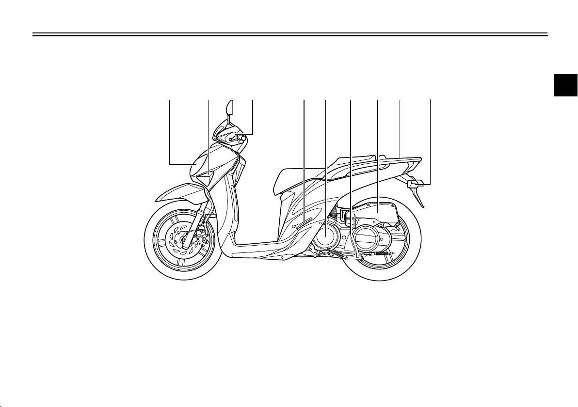
Left view
1, 2 3 4 5 6 7 8 9 10
Description
EAU10411
1
2
3
4
5
6
7
8
9
1. Headlight (page 6-28)
2. Auxiliary light (page 6-29)
3. Front turn signal light (page 6-30)
4. Front brake fluid reservoir (page 6-22)
5. Passenger footrest (page 3-11)
6. V-belt air filter case cover (page 6-16)
7. Centerstand (page 6-24)
8. Air filter (page 6-16)
9. Carrier (page 3-14)
10.Rear turn signal light (page 6-31)
2-1
10
11
12
Description
1 2 3, 4 5 6 7 8 9, 10
1
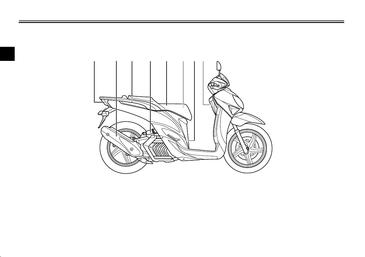
Right view
2
3
4
5
6
7
8
9
EAU10421
1. Tail/brake light (page 6-30)
10
2. Muffler (page 3-10)
3. Fuel tank cap (page 3-8)
4. Coolant reservoir (page 6-14)
11
5. Shock absorber assembly (page 3-13)
6. Seat (page 3-11)
12
7. Rear storage compartment (page 3-12)
8. Spark plug (page 6-10)
9. Battery (page 6-26)
10.Fuse box (page 6-28)
2-2
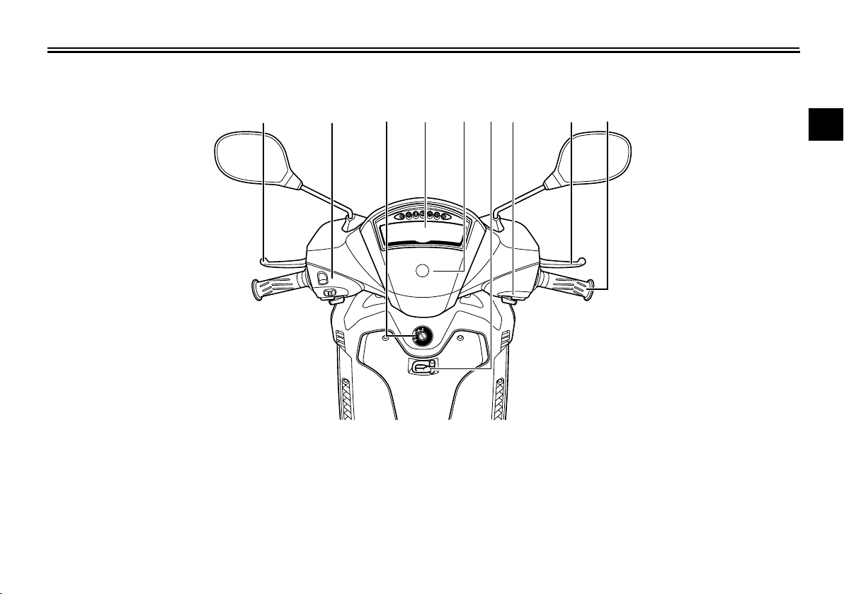
Controls and instruments
1 2 3 4 5 6 7 8 9
Description
EAU10431
1
2
3
4
5
1. Rear brake lever (page 3-8)
2. Left handlebar switches (page 3-7)
3. Main switch/steering lock (page 3-1)
4. Multi-function display (page 3-3)
5. Front storage compartment (page 3-12)
6. Luggage holder (page 3-14)
7. Right handlebar switch (page 3-7)
8. Front brake lever (page 3-7)
6
7
8
9
9. Throttle grip (page 6-17)
10
11
12
2-3
Instrument and control functions
TIP
WARNING
TIP
ON
OFF
LOCK
1
2
1
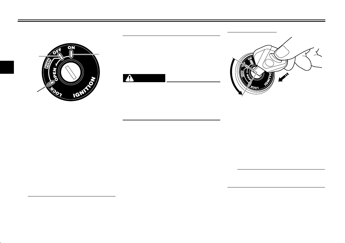
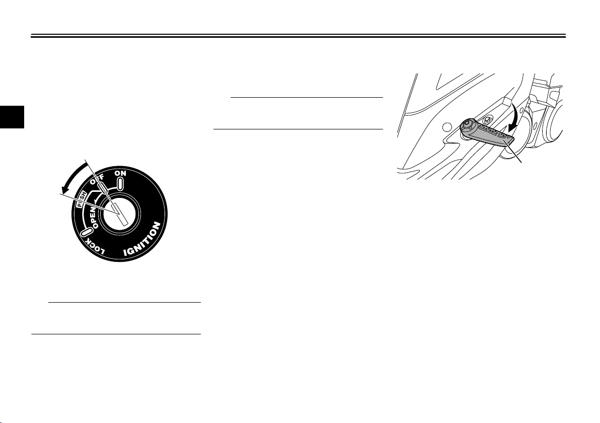
Main switch/steering lock
2
3
4
5
The main switch/steering lock controls
6
the ignition and lighting systems, and is
used to lock the steering. The various
positions are described below.
7
8
ON
All electrical circuits are supplied with
power, the meter lighting, taillight, li-
9
cense plate light and auxiliary lights
come on, and the engine can be start-
10
ed. The key cannot be removed.
11
The headlights come on automatically
when the engine is started and stay on
12
until the key is turned to “OFF”, even if
EAU10462
EAU10551
the engine stalls.
EAU10662
OFF
All electrical systems are off. The key
can be removed.
EWA10062
Never turn the key to “OFF” or
“LOCK” while the vehicle is moving.
Otherwise the electrical systems will
be switched off, which may result in
loss of control or an accident.
EAU10687
LOCK
The steering is locked and all electrical
systems are off. The key can be removed.
To lock the steering
1. Push.
2. Turn.
1. Turn the handlebars all the way to
the left.
2. With the key in the “OFF” position,
push the key in and turn it to
“LOCK”.
3. Remove the key.
If the steering will not lock, try turning
the handlebars back to the right slightly.
3-1
Instrument and control functions
NOTICE
TIP
2
1
SELECT
RESET
ODO
OIL TRIP 1 BELT TRIP 2
OIL CHANGE
CLOOK
OUT TEMP
3
2
4
11
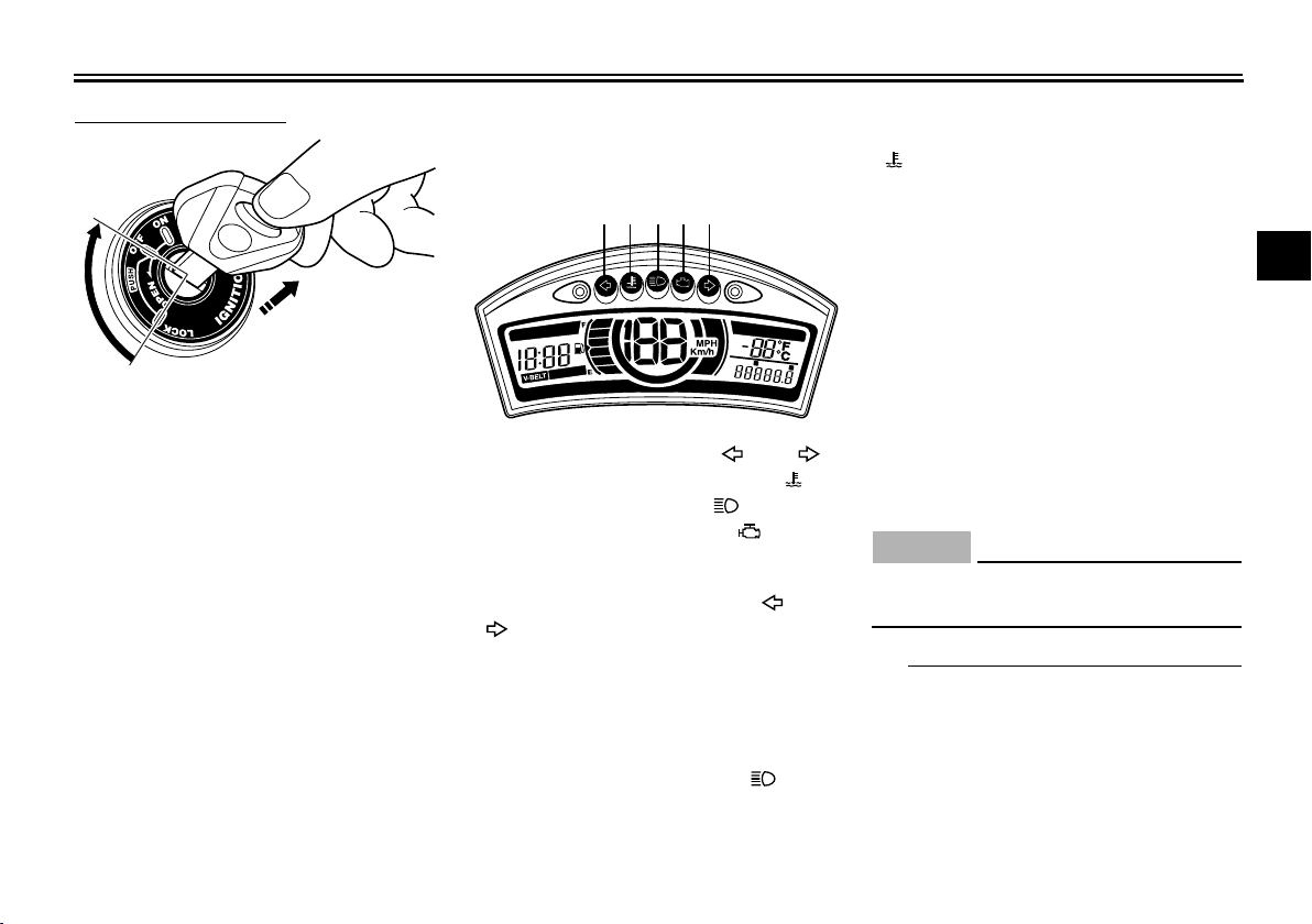
To unlock the steering
1. Turn.
2. Release.
1. Insert the key.
2. With the key in the “LOCK” position, push the key in and turn it to
“OFF”.
EAU49398
Indicator lights and warning lights
1. Turn signal indicator lights “ ” and “ ”
2. Coolant temperature warning light “ ”
3. High beam indicator light “ ”
4. Engine trouble warning light “ ”
EAU11032
Turn signal indicator lights “ ” and
“”
Each indicator light will flash when its
corresponding turn signal lights are
flashing.
EAU11081
High beam indicator light “ ”
This indicator light comes on when the
high beam of the headlight is switched
on.
3-2
EAU11447
Coolant temperature warning light
“”
This warning light comes on if the engine overheats. If this occurs, stop the
engine immediately and allow the engine to cool.
The electrical circuit of the warning light
can be checked by turning the key to
“ON”. The warning light should come
on for a few seconds, and then go off.
If the warning light does not come on
initially when the key is turned to “ON”,
or if the warning light remains on, have
a Yamaha dealer check the electrical
circuit.
ECA10022
Do not continue to operate the engine if it is overheating.
For radiator-fan-equipped vehi-
cles, the radiator fan(s) automatically switch on or off according to
the coolant temperature in the radiator.
If the engine overheats, see page
1
2
3
4
5
6
7
8
9
10
11
12
Instrument and control functions
WARNING
SELECT
RESET
ODO
OI
L
TRIP 1 BELT TRIP
2
OIL CHANGE
CLOOK
OUT TEMP
1
2
3
456
78
9
10
12
11
1
2
6-34 for further instructions.
Engine trouble warning light “ ”
This warning light flashes or stays on if
an electrical circuit monitoring the en-
3
gine is not working correctly. If this occurs, have a Yamaha dealer check the
4
self-diagnosis system.
The electrical circuit of the warning light
5
can be checked by turning the key to
“ON”. The warning light should come
on for a few seconds, and then go off.
6
If the warning light does not come on
initially when the key is turned to “ON”,
7
or if the warning light remains on, have
a Yamaha dealer check the electrical
8
circuit.
9
10
11
12
EAUT3725
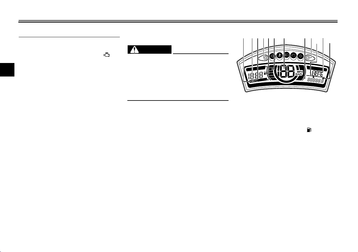
Multi-function display
EAUT1936
Be sure to stop the vehicle before
making any setting changes to the
multi-function display. Changing
settings while riding can distract the
operator and increase the risk of an
accident.
3-3
EWA12313
1. V-belt replacement indicator “V-BELT”
2. Clock
3. Oil change indicator “OIL CHANGE”
4. “SELECT” button
5. Fuel level warning indicator “ ”
6. Fuel meter
7. Speedometer
8. Odometer
9. “RESET” button
10.Tripmeter 1
11.Ambient temperature display
12.Tripmeter 2
The multi-function display is equipped
with the following:
an odometer
a fuel reserve tripmeter (which
shows the distance traveled since
the bottom segment of the fuel meter and fuel level warning indicator

Instrument and control functions
TIP
TIP
TIP
started flashing)
two tripmeters (which show the
distance traveled since they were
last set to zero)
an oil change tripmeter (which
shows the distance traveled since
the last engine oil change)
an oil change indicator (which dis-
plays when the engine oil should
be changed)
a V-belt replacement tripmeter
(which shows the distance traveled since the V-belt was last replaced)
a V-belt replacement indicator
an ambient temperature display
a clock
a fuel meter
a brightness control mode
When the key is turned to “ON”, all
segments of the display come on
for a few seconds. During this
time, the multi-function display is
performing a self-test.
Be sure to turn the key to “ON” be-
fore using the “SELECT” and “RESET” buttons except when setting
the brightness mode.
Odometer, fuel tripmeter, tripmeters, oil change tripmeter and V-belt
tripmeter modes
Pushing the “SELECT” button switches
the display among the odometer mode
“ODO”, the fuel tripmeter mode “F”, the
tripmeter modes “TRIP 1” and “TRIP 2”,
the oil change tripmeter mode “OIL
TRIP” and the V-belt change mode
“BELT TRIP” in the following order:
ODO F TRIP 1 TRIP 2 OIL
TRIP BELT TRIP ODO
When approximately 1.6 L (0.42 US
gal, 0.35 Imp.gal) of fuel remains in the
fuel tank, the bottom segment of the
fuel meter and fuel level warning indicator will start flashing, and the display will
automatically change to the fuel reserve tripmeter mode " F" and start
counting the distance traveled from that
point. In that case, pushing the "RESET" button switches the display to the
previous mode.
To reset a tripmeter, select it by pushing the “SELECT” button until “Trip” or
“Trip F” begins flashing (“Trip” or “Trip
3-4
F” will only flash for five seconds).
While “Trip” or “Trip F” is flashing, push
the “RESET” button for at least one
second. If you do not reset the fuel reserve tripmeter manually, it will reset itself automatically and the display will
return to the prior mode after refueling
and traveling 5 km (3 mi).
The display cannot be changed back to
fuel reserve tripmeter “F” after pushing
the “RESET” button.
Odometer
For the U.K.: For any mode, the
odometer units can be switched
from kilometers to miles by pushing the “SELECT” button for 1 second.
If the odometer indicates “-----”,
have a Yamaha dealer check the
multi-function display, as it may be
faulty.
Tripmeters
To reset a tripmeter, select it by push-
1
2
3
4
5
6
7
8
9
10
11
12

Instrument and control functions
TIP
TIP
TIP
10
11
12
ing the “SELECT” button until “TRIP 1”
1
or “TRIP 2” is displayed, and then push
the “RESET” button for at least 1 sec-
2
ond.
3
If the tripmeter indicates “-----”, have a
Yamaha dealer check the multi-function display, as it may be faulty.
4
5
Oil change tripmeter
To reset the oil change tripmeter, select
it by pushing the “SELECT” button until
6
“OIL CHANGE” and “OIL TRIP” are displayed, and then push the “RESET”
7
button for at least 3 seconds. After resetting, “OIL CHANGE” will disappear.
Push the “SELECT” button again to
8
start the oil change tripmeter; the display changes to V-belt tripmeter mode.
9
Oil change indicator “OIL
CHANGE”
This indicator will display at the initial
1000 km (625 mi), then at every 6000
km (3750 mi) thereafter to indicate that
the engine oil should be changed.
After changing the engine oil, reset the
oil change tripmeter.
If the engine oil is changed before the
oil change indicator displays (i.e. before
the periodic oil change interval has
been reached), the oil change tripmeter
must be reset after the oil change for
the next periodic oil change to be indicated at the correct time.
If the oil change tripmeter is reset
before the initial 1000 km (625 mi),
the next periodic oil change interval will be at every 6000 km (3750
mi) thereafter.
If the oil change tripmeter indicates
“-----”, have a Yamaha dealer
check the multi-function display,
as it may be faulty.
V-belt replacement tripmeter
To reset the V-belt tripmeter, select it
by pushing the “SELECT” button until
“V-BELT” and “BELT TRIP” are displayed, and then push the “RESET”
button for at least 3 seconds. After resetting, “V-BELT” will disappear.
Push the “SELECT” button again to
start the V-belt tripmeter; the display
changes to ODO mode.
3-5
V-belt change indicator “V-BELT”
This indicator comes on at every 20000
km (12500 mi) to indicate that the
V-belt should be replaced.
After replacing the V-belt, reset the
V-belt tripmeter.
If the V-belt is replaced before the
V-belt indicator comes on (i.e., before
the periodic V-belt replacement interval
has been reached), the V-belt tripmeter
must be reset after replacing the V-belt
for the next periodic V-belt replacement
to be indicated at the correct time.
If the V-belt change indicator displays
“-----”, have a Yamaha dealer check the
multi-function display, as it may be
faulty.
Ambient temperature display “OUT
TEMP”
This display shows the ambient temperature from –10 C to 40 C in 1 C
increments. The temperature displayed
may vary from the ambient temperature.

Instrument and control functions
TIP
If the ambient temperature falls be-
low –10 C, a lower temperature
than –10 C will not be displayed.
If the ambient temperature climbs
above 40 C, a higher temperature
than 40 C will not be displayed.
The accuracy of the temperature
reading may be affected when riding slowly (approximately under 20
km/h (12 mi/h)) or when stopped at
traffic signals, railroad crossings,
etc.
Clock
To set the clock:
1. Push the “SELECT” button and
“RESET” button together for at
least two seconds.
2. When the hour digits start flashing,
push the “RESET” button to set the
hours.
3. Push the “SELECT” button, and
the minute digits will start flashing.
4. Push the “RESET” button to set
the minute digits.
5. Push the “SELECT” button and
then release it to start the clock.
Fuel meter
The fuel meter indicates the amount of
fuel in the fuel tank. The display segments of the fuel meter disappear towards “E” (Empty) as the fuel level
decreases. When the bottom segment
of the fuel meter and fuel level warning
indicator “*” starts flashing, refuel as
soon as possible. When the key is
turned to “ON”, all of the display segments of the fuel meter will appear for a
few seconds, and then shows the actual fuel level.
Brightness control mode
This function allows you to adjust the
brightness of the speedometer panel to
suit the outside lighting conditions.
To set the brightness
1. Turn the key to “OFF”.
2. Push and hold the “SELECT” button.
3. Turn the key to “ON”, and then release the “SELECT” button after
five seconds. The display will
change to brightness control
3-6
mode.
4. Push the “RESET” button to select
the desired brightness level in the
following order: BL-01 BL-02
BL-03 BL-04 BL-05
BL-01.
5. Turn the key to “OFF”.
1
2
3
4
5
6
7
8
9
10
11
12
Instrument and control functions
1
3
2
1
1
1
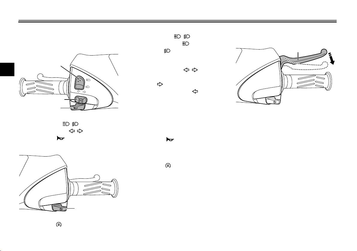
Handlebar switches
Left
2
3
4
5
6
1. Dimmer switch “ / ”
2. Turn signal switch “ / ”
7
3. Horn switch “ ”
Right
8
9
10
11
EAU1234H
Dimmer switch “ / ”
EAU12401
EAUS2012
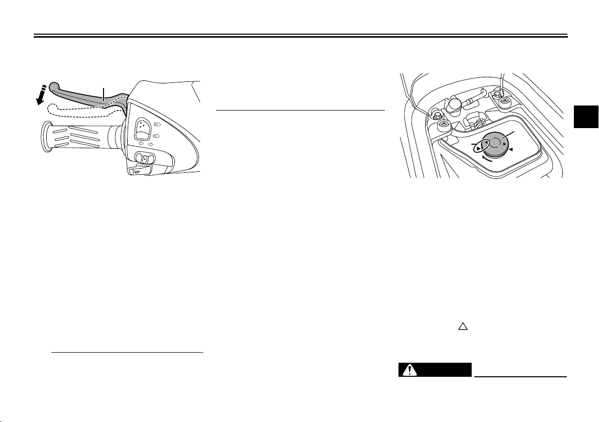
Front brake lever
Set this switch to “ ” for the high
beam and to “ ” for the low beam.
EAU12461
Turn signal switch “ / ”
To signal a right-hand turn, push this
switch to “ ”. To signal a left-hand
turn, push this switch to “ ”. When released, the switch returns to the center
position. To cancel the turn signal
lights, push the switch in after it has re-
1. Front brake lever
turned to the center position.
The front brake lever is located on the
EAU12501
Horn switch “ ”
Press this switch to sound the horn.
EAUM1133
Start switch “ ”
Push this switch while applying the
front or rear brake to crank the engine
with the starter. See page 5-1 for starting instructions prior to starting the engine.
right side of the handlebar. To apply the
front brake, pull this lever toward the
throttle grip.
This model is equipped with a unified
brake system.
As this system is mechanical, additional free play can be felt in the front brake
lever when the rear brake lever is being
applied. See “Rear brake lever” for detailed information on the unified brake
system.
12
1. Start switch “ ”
3-7
Instrument and control functions
TIP
WARNING
1
1
2
EAUS1963
Rear brake lever
1. Rear brake lever
The rear brake lever is located on the
left handlebar grip. To apply the rear
brake, pull the lever toward the handlebar grip.
This model is equipped with a unified
brake system.
When pulling the rear brake lever, the
rear brake and a portion of the front
brake are applied. For full braking performance, apply both brake levers simultaneously.
As the unified brake system is me-
chanical, additional free play can
be felt in the front brake lever when
the rear brake lever is being
pulled.
The unified brake system does not
function when the front brake is
applied alone.
EAUT3591
Fuel tank cap
1. Fuel tank cap
2. Match marks
To remove the fuel tank cap
1. Open the seat. (See page 3-11.)
2. Turn the fuel tank cap counterclockwise and pull it off.
To install the fuel tank cap
1. Insert the fuel tank cap into the
tank opening and turn it clockwise
until the “ ” marks on the cap and
rubber mat are aligned.
2. Close the seat.
EWA11092
Make sure that the fuel tank cap is
1
2
3
4
5
6
7
8
9
10
11
12
3-8
Instrument and control functions
WARNING
WARNING
1
2
properly closed after filling fuel.
1
Leaking fuel is a fire hazard.
2
3
4
5
6
7
8
9
10
11
12
EAU13222
Fuel
Make sure there is sufficient gasoline in
the tank.
Gasoline and gasoline vapors are
extremely flammable. To avoid fires
and explosions and to reduce the
risk of injury when refueling, follow
these instructions.
1. Before refueling, turn off the engine and be sure that no one is sitting on the vehicle. Never refuel
while smoking, or while in the vicinity of sparks, open flames, or
other sources of ignition such as
the pilot lights of water heaters and
clothes dryers.
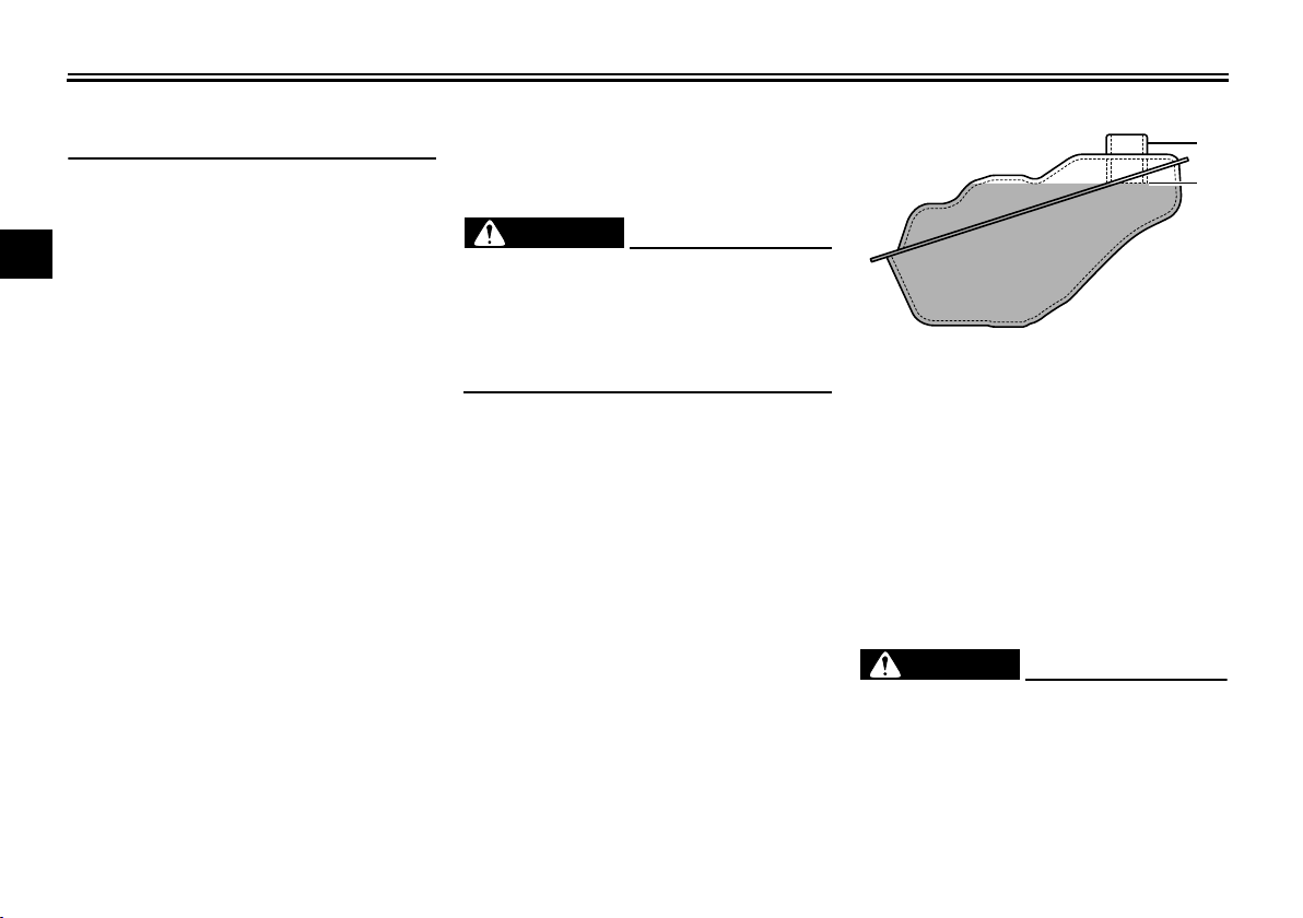
2. Do not overfill the fuel tank. When
refueling, be sure to insert the
pump nozzle into the fuel tank filler
hole. Stop filling when the fuel
reaches the bottom of the filler
tube. Because fuel expands when
it heats up, heat from the engine or
the sun can cause fuel to spill out
of the fuel tank.
EWA10882
1. Fuel tank filler tube
2. Maximum fuel level
3. Wipe up any spilled fuel immediately. NOTICE: Immediately wipe
off spilled fuel with a clean, dry,
soft cloth, since fuel may deteriorate painted surfaces or plastic
[ECA10072]
parts.
4. Be sure to securely close the fuel
tank cap.
EWA15152
Gasoline is poisonous and can
cause injury or death. Handle gasoline with care. Never siphon gasoline by mouth. If you should swallow
some gasoline or inhale a lot of gasoline vapor, or get some gasoline in
3-9
Instrument and control functions
NOTICE
WARNING
NOTICE
your eyes, see your doctor immediately. If gasoline spills on your skin,
wash with soap and water. If gasoline spills on your clothing, change
your clothes.
EAU33524
Recommended fuel:
Regular unleaded gasoline only
Fuel tank capacity:
8.0 L (2.1 US gal, 1.8 Imp.gal)
ECA11401
Use only unleaded gasoline. The use
of leaded gasoline will cause severe
damage to internal engine parts,
such as the valves and piston rings,
as well as to the exhaust system.
Your Yamaha engine has been designed to use regular unleaded gasoline with a research octane number of
95 or higher. If knocking (or pinging) occurs, use a gasoline of a different brand
or premium unleaded fuel. Use of unleaded fuel will extend spark plug life
and reduce maintenance costs.
EAU13434
Catalytic converter
This model is equipped with a catalytic
converter in the exhaust system.
EWA10863
The exhaust system is hot after operation. To prevent a fire hazard or
burns:
Do not park the vehicle near
possible fire hazards such as
grass or other materials that
easily burn.
Park the vehicle in a place
where pedestrians or children
are not likely to touch the hot
exhaust system.
Make sure that the exhaust sys-
tem has cooled down before doing any maintenance work.
Do not allow the engine to idle
more than a few minutes. Long
idling can cause a build-up of
heat.
ECA10702
Use only unleaded gasoline. The use
of leaded gasoline will cause unre-
pairable damage to the catalytic
converter.
1
2
3
4
5
6
7
8
9
10
11
12
3-10
Instrument and control functions
TIP
TIP
1
1
1
Seat
To open the seat
2
1. Place the scooter on the center-
3
stand.
2. Insert the key into the main switch,
and then turn it counterclockwise
4
to “OPEN”.
5
6
7
8
1. Turn.
9
Do not push inward when turning the
10
key.
11
3. Fold the seat up.
EAU13933
2. Remove the key from the main
switch if the scooter will be left unattended.
Make sure that the seat is properly secured before riding.
EAUT3711
Passenger footrest
1. Passenger footrest
To use the passenger footrest, pull it
out as shown.
To retract the passenger footrest, push
it back to original position.
12
To close the seat
1. Fold the seat down, and then push
it down to lock it in place.
3-11
 Loading...