

Page 1

AV Receiver
Owner’s Manual
English
Read the supplied booklet “Safety Brochure” before using the unit.
Page 2

CONTENTS
Accessories . . . . . . . . . . . . . . . . . . . . . . . . . . . . . . . . . . . . . . . . . . . . . . . . . . . . . . 5
FEATURES 6
What you can do with the unit . . . . . . . . . . . . . . . . . . . . . . . . . . . . . . . . . . . . 6
Part names and functions . . . . . . . . . . . . . . . . . . . . . . . . . . . . . . . . . . . . . . . . 8
Front panel (HTR-7065) . . . . . . . . . . . . . . . . . . . . . . . . . . . . . . . . . . . . . . . . . . . . . . . . . . . . . . . . . . . . . . . . . . . . . . . . . . . . . 8
Front panel (HTR-6065) . . . . . . . . . . . . . . . . . . . . . . . . . . . . . . . . . . . . . . . . . . . . . . . . . . . . . . . . . . . . . . . . . . . . . . . . . . . . . 9
Front display (indicators) . . . . . . . . . . . . . . . . . . . . . . . . . . . . . . . . . . . . . . . . . . . . . . . . . . . . . . . . . . . . . . . . . . . . . . . . . . 10
Rear panel (HTR-7065) . . . . . . . . . . . . . . . . . . . . . . . . . . . . . . . . . . . . . . . . . . . . . . . . . . . . . . . . . . . . . . . . . . . . . . . . . . . . . 11
Rear panel (HTR-6065) . . . . . . . . . . . . . . . . . . . . . . . . . . . . . . . . . . . . . . . . . . . . . . . . . . . . . . . . . . . . . . . . . . . . . . . . . . . . . 12
Remote control . . . . . . . . . . . . . . . . . . . . . . . . . . . . . . . . . . . . . . . . . . . . . . . . . . . . . . . . . . . . . . . . . . . . . . . . . . . . . . . . . . . 13
PREPARATIONS 14
General setup procedure . . . . . . . . . . . . . . . . . . . . . . . . . . . . . . . . . . . . . . . . 14
1 Placing speakers . . . . . . . . . . . . . . . . . . . . . . . . . . . . . . . . . . . . . . . . . . . . . . 15
2 Connecting speakers . . . . . . . . . . . . . . . . . . . . . . . . . . . . . . . . . . . . . . . . . . 19
Connecting front speakers that support bi-amp connections . . . . . . . . . . . . . . . . . . . . . . . . . . . . . . . . . . . . . . . 21
Input/output jacks and cables . . . . . . . . . . . . . . . . . . . . . . . . . . . . . . . . . . . 22
3 Connecting a TV . . . . . . . . . . . . . . . . . . . . . . . . . . . . . . . . . . . . . . . . . . . . . . . 23
4 Connecting playback devices . . . . . . . . . . . . . . . . . . . . . . . . . . . . . . . . . . 28
Connecting video devices (such as BD/DVD players) . . . . . . . . . . . . . . . . . . . . . . . . . . . . . . . . . . . . . . . . . . . . . . . 28
Connecting audio devices (such as CD players) . . . . . . . . . . . . . . . . . . . . . . . . . . . . . . . . . . . . . . . . . . . . . . . . . . . . . 31
Connecting to the jacks on the front panel . . . . . . . . . . . . . . . . . . . . . . . . . . . . . . . . . . . . . . . . . . . . . . . . . . . . . . . . . 31
5 Connecting the FM/AM antennas . . . . . . . . . . . . . . . . . . . . . . . . . . . . . . . 32
6 Connecting to a network . . . . . . . . . . . . . . . . . . . . . . . . . . . . . . . . . . . . . . . 32
7 Connecting other devices . . . . . . . . . . . . . . . . . . . . . . . . . . . . . . . . . . . . . . 33
Connecting an external power amplifier . . . . . . . . . . . . . . . . . . . . . . . . . . . . . . . . . . . . . . . . . . . . . . . . . . . . . . . . . . . 33
Connecting recording devices . . . . . . . . . . . . . . . . . . . . . . . . . . . . . . . . . . . . . . . . . . . . . . . . . . . . . . . . . . . . . . . . . . . . .33
Connecting a device that supports SCENE link playback (remote connection) . . . . . . . . . . . . . . . . . . . . . . .34
Connecting a device compatible with the trigger function . . . . . . . . . . . . . . . . . . . . . . . . . . . . . . . . . . . . . . . . . . 34
8 Connecting the power cable . . . . . . . . . . . . . . . . . . . . . . . . . . . . . . . . . . . 35
9 Selecting an on-screen menu language . . . . . . . . . . . . . . . . . . . . . . . . . 36
10 Optimizing the speaker settings automatically (YPAO) . . . . . . . . . 37
Measuring at one listening position (single measure) . . . . . . . . . . . . . . . . . . . . . . . . . . . . . . . . . . . . . . . . . . . . . . .39
Measuring at multiple listening positions (multi measure) (HTR-7065 only) . . . . . . . . . . . . . . . . . . . . . . . . . .40
Checking the measurement results . . . . . . . . . . . . . . . . . . . . . . . . . . . . . . . . . . . . . . . . . . . . . . . . . . . . . . . . . . . . . . . .41
Reloading the previous YPAO adjustments . . . . . . . . . . . . . . . . . . . . . . . . . . . . . . . . . . . . . . . . . . . . . . . . . . . . . . . . . 42
Error messages . . . . . . . . . . . . . . . . . . . . . . . . . . . . . . . . . . . . . . . . . . . . . . . . . . . . . . . . . . . . . . . . . . . . . . . . . . . . . . . . . . . .43
Warning messages . . . . . . . . . . . . . . . . . . . . . . . . . . . . . . . . . . . . . . . . . . . . . . . . . . . . . . . . . . . . . . . . . . . . . . . . . . . . . . . .44
PLAYBACK 45
Basic playback procedure . . . . . . . . . . . . . . . . . . . . . . . . . . . . . . . . . . . . . . . 45
Selecting an HDMI output jack (HTR-7065 only) . . . . . . . . . . . . . . . . . . . . . . . . . . . . . . . . . . . . . . . . . . . . . . . . . . . . 45
Selecting the input source and favorite settings with one touch
(SCENE) . . . . . . . . . . . . . . . . . . . . . . . . . . . . . . . . . . . . . . . . . . . . . . . . . . . . . . . . 46
Configuring scene assignments . . . . . . . . . . . . . . . . . . . . . . . . . . . . . . . . . . . . . . . . . . . . . . . . . . . . . . . . . . . . . . . . . . . . 46
Selecting the sound mode . . . . . . . . . . . . . . . . . . . . . . . . . . . . . . . . . . . . . . . 47
Enjoying sound field effects (CINEMA DSP) . . . . . . . . . . . . . . . . . . . . . . . . . . . . . . . . . . . . . . . . . . . . . . . . . . . . . . . . .48
Enjoying unprocessed playback . . . . . . . . . . . . . . . . . . . . . . . . . . . . . . . . . . . . . . . . . . . . . . . . . . . . . . . . . . . . . . . . . . . 50
Enjoying pure high fidelity sound (Pure Direct) . . . . . . . . . . . . . . . . . . . . . . . . . . . . . . . . . . . . . . . . . . . . . . . . . . . . .51
Enjoying compressed music with enhanced sound (Compressed Music Enhancer) . . . . . . . . . . . . . . . . . . .52
Enjoying surround sound with headphones (SILENT CINEMA) . . . . . . . . . . . . . . . . . . . . . . . . . . . . . . . . . . . . . . . 52
Listening to FM/AM radio . . . . . . . . . . . . . . . . . . . . . . . . . . . . . . . . . . . . . . . 53
Selecting a frequency for reception . . . . . . . . . . . . . . . . . . . . . . . . . . . . . . . . . . . . . . . . . . . . . . . . . . . . . . . . . . . . . . . .53
Registering favorite radio stations (presets) . . . . . . . . . . . . . . . . . . . . . . . . . . . . . . . . . . . . . . . . . . . . . . . . . . . . . . . . 54
En 2
Page 3

Radio Data System tuning . . . . . . . . . . . . . . . . . . . . . . . . . . . . . . . . . . . . . . . . . . . . . . . . . . . . . . . . . . . . . . . . . . . . . . . . . 55
Operating the radio on the TV . . . . . . . . . . . . . . . . . . . . . . . . . . . . . . . . . . . . . . . . . . . . . . . . . . . . . . . . . . . . . . . . . . . . . 56
Playing back iPod music . . . . . . . . . . . . . . . . . . . . . . . . . . . . . . . . . . . . . . . . . 58
Connecting an iPod . . . . . . . . . . . . . . . . . . . . . . . . . . . . . . . . . . . . . . . . . . . . . . . . . . . . . . . . . . . . . . . . . . . . . . . . . . . . . . . 58
Playback of iPod content . . . . . . . . . . . . . . . . . . . . . . . . . . . . . . . . . . . . . . . . . . . . . . . . . . . . . . . . . . . . . . . . . . . . . . . . . . 59
Playing back music stored on a USB storage device . . . . . . . . . . . . . . . 62
Connecting a USB storage device . . . . . . . . . . . . . . . . . . . . . . . . . . . . . . . . . . . . . . . . . . . . . . . . . . . . . . . . . . . . . . . . . . 62
Playback of USB storage device contents . . . . . . . . . . . . . . . . . . . . . . . . . . . . . . . . . . . . . . . . . . . . . . . . . . . . . . . . . . 62
Playing back music stored on media servers (PCs/NAS) . . . . . . . . . . . . 65
Media sharing setup . . . . . . . . . . . . . . . . . . . . . . . . . . . . . . . . . . . . . . . . . . . . . . . . . . . . . . . . . . . . . . . . . . . . . . . . . . . . . . 65
Playback of PC music contents . . . . . . . . . . . . . . . . . . . . . . . . . . . . . . . . . . . . . . . . . . . . . . . . . . . . . . . . . . . . . . . . . . . . 65
Listening to Internet radio . . . . . . . . . . . . . . . . . . . . . . . . . . . . . . . . . . . . . . . 68
Playing back iTunes/iPod music via a network (AirPlay) . . . . . . . . . . . 70
Playback of iTunes/iPod music contents . . . . . . . . . . . . . . . . . . . . . . . . . . . . . . . . . . . . . . . . . . . . . . . . . . . . . . . . . . . 70
Playing back music in multiple rooms (multi-zone) . . . . . . . . . . . . . . . . 72
Preparing Zone2 . . . . . . . . . . . . . . . . . . . . . . . . . . . . . . . . . . . . . . . . . . . . . . . . . . . . . . . . . . . . . . . . . . . . . . . . . . . . . . . . . . 72
Controlling Zone2 . . . . . . . . . . . . . . . . . . . . . . . . . . . . . . . . . . . . . . . . . . . . . . . . . . . . . . . . . . . . . . . . . . . . . . . . . . . . . . . . 75
Viewing the current status . . . . . . . . . . . . . . . . . . . . . . . . . . . . . . . . . . . . . . 77
Switching information on the front display . . . . . . . . . . . . . . . . . . . . . . . . . . . . . . . . . . . . . . . . . . . . . . . . . . . . . . . . 77
Viewing the status information on the TV . . . . . . . . . . . . . . . . . . . . . . . . . . . . . . . . . . . . . . . . . . . . . . . . . . . . . . . . . . 77
Configuring playback settings for different playback sources
(Option menu) . . . . . . . . . . . . . . . . . . . . . . . . . . . . . . . . . . . . . . . . . . . . . . . . . . 78
Option menu items . . . . . . . . . . . . . . . . . . . . . . . . . . . . . . . . . . . . . . . . . . . . . . . . . . . . . . . . . . . . . . . . . . . . . . . . . . . . . . . 78
CONFIGURATIONS 81
Sound Program menu items . . . . . . . . . . . . . . . . . . . . . . . . . . . . . . . . . . . . . . . . . . . . . . . . . . . . . . . . . . . . . . . . . . . . . . . 86
Configuring various functions (Setup menu) . . . . . . . . . . . . . . . . . . . . . . 88
Setup menu items . . . . . . . . . . . . . . . . . . . . . . . . . . . . . . . . . . . . . . . . . . . . . . . . . . . . . . . . . . . . . . . . . . . . . . . . . . . . . . . . . 89
Speaker (Manual Setup) . . . . . . . . . . . . . . . . . . . . . . . . . . . . . . . . . . . . . . . . . . . . . . . . . . . . . . . . . . . . . . . . . . . . . . . . . . . 91
Sound . . . . . . . . . . . . . . . . . . . . . . . . . . . . . . . . . . . . . . . . . . . . . . . . . . . . . . . . . . . . . . . . . . . . . . . . . . . . . . . . . . . . . . . . . . . . 94
Video . . . . . . . . . . . . . . . . . . . . . . . . . . . . . . . . . . . . . . . . . . . . . . . . . . . . . . . . . . . . . . . . . . . . . . . . . . . . . . . . . . . . . . . . . . . . . 95
HDMI . . . . . . . . . . . . . . . . . . . . . . . . . . . . . . . . . . . . . . . . . . . . . . . . . . . . . . . . . . . . . . . . . . . . . . . . . . . . . . . . . . . . . . . . . . . . .96
Network . . . . . . . . . . . . . . . . . . . . . . . . . . . . . . . . . . . . . . . . . . . . . . . . . . . . . . . . . . . . . . . . . . . . . . . . . . . . . . . . . . . . . . . . . . 98
Multi Zone . . . . . . . . . . . . . . . . . . . . . . . . . . . . . . . . . . . . . . . . . . . . . . . . . . . . . . . . . . . . . . . . . . . . . . . . . . . . . . . . . . . . . . . . 99
Function . . . . . . . . . . . . . . . . . . . . . . . . . . . . . . . . . . . . . . . . . . . . . . . . . . . . . . . . . . . . . . . . . . . . . . . . . . . . . . . . . . . . . . . . .100
ECO . . . . . . . . . . . . . . . . . . . . . . . . . . . . . . . . . . . . . . . . . . . . . . . . . . . . . . . . . . . . . . . . . . . . . . . . . . . . . . . . . . . . . . . . . . . . . .102
Language . . . . . . . . . . . . . . . . . . . . . . . . . . . . . . . . . . . . . . . . . . . . . . . . . . . . . . . . . . . . . . . . . . . . . . . . . . . . . . . . . . . . . . . .103
Viewing information about the unit (Information menu) . . . . . . . . . 103
Types of information . . . . . . . . . . . . . . . . . . . . . . . . . . . . . . . . . . . . . . . . . . . . . . . . . . . . . . . . . . . . . . . . . . . . . . . . . . . . .104
Configuring the system settings (ADVANCED SETUP menu) . . . . . . 105
ADVANCED SETUP menu items . . . . . . . . . . . . . . . . . . . . . . . . . . . . . . . . . . . . . . . . . . . . . . . . . . . . . . . . . . . . . . . . . . .105
Changing the speaker impedance setting (SP IMP.) . . . . . . . . . . . . . . . . . . . . . . . . . . . . . . . . . . . . . . . . . . . . . . . .105
Selecting the remote control ID (REMOTE ID) . . . . . . . . . . . . . . . . . . . . . . . . . . . . . . . . . . . . . . . . . . . . . . . . . . . . . .106
Switching the video signal type (TV FORMAT) . . . . . . . . . . . . . . . . . . . . . . . . . . . . . . . . . . . . . . . . . . . . . . . . . . . . .106
Removing the limitation on HDMI video output (MON.CHK) . . . . . . . . . . . . . . . . . . . . . . . . . . . . . . . . . . . . . . .106
Restoring the default settings (INIT) . . . . . . . . . . . . . . . . . . . . . . . . . . . . . . . . . . . . . . . . . . . . . . . . . . . . . . . . . . . . . . .106
Updating the firmware (UPDATE) . . . . . . . . . . . . . . . . . . . . . . . . . . . . . . . . . . . . . . . . . . . . . . . . . . . . . . . . . . . . . . . . .107
Checking the firmware version (VERSION) . . . . . . . . . . . . . . . . . . . . . . . . . . . . . . . . . . . . . . . . . . . . . . . . . . . . . . . . .107
Controlling external devices with the remote control . . . . . . . . . . . . 108
Registering the remote control code for a TV . . . . . . . . . . . . . . . . . . . . . . . . . . . . . . . . . . . . . . . . . . . . . . . . . . . . . .108
Registering the remote control codes for playback devices . . . . . . . . . . . . . . . . . . . . . . . . . . . . . . . . . . . . . . . .109
Resetting remote control codes . . . . . . . . . . . . . . . . . . . . . . . . . . . . . . . . . . . . . . . . . . . . . . . . . . . . . . . . . . . . . . . . . . .110
Updating the unit’s firmware . . . . . . . . . . . . . . . . . . . . . . . . . . . . . . . . . . . 111
Configuring input sources (Input menu) . . . . . . . . . . . . . . . . . . . . . . . . . . 81
Input menu items . . . . . . . . . . . . . . . . . . . . . . . . . . . . . . . . . . . . . . . . . . . . . . . . . . . . . . . . . . . . . . . . . . . . . . . . . . . . . . . . . 81
Configuring the SCENE function (Scene menu) . . . . . . . . . . . . . . . . . . . . 83
Scene menu items . . . . . . . . . . . . . . . . . . . . . . . . . . . . . . . . . . . . . . . . . . . . . . . . . . . . . . . . . . . . . . . . . . . . . . . . . . . . . . . . 84
Configuring sound programs/surround decoders
(Sound Program menu) . . . . . . . . . . . . . . . . . . . . . . . . . . . . . . . . . . . . . . . . . 85
En 3
Page 4

APPENDIX 112
Frequently asked questions . . . . . . . . . . . . . . . . . . . . . . . . . . . . . . . . . . . .112
Troubleshooting . . . . . . . . . . . . . . . . . . . . . . . . . . . . . . . . . . . . . . . . . . . . . . . 113
Power and system . . . . . . . . . . . . . . . . . . . . . . . . . . . . . . . . . . . . . . . . . . . . . . . . . . . . . . . . . . . . . . . . . . . . . . . . . . . . . . . 113
Audio . . . . . . . . . . . . . . . . . . . . . . . . . . . . . . . . . . . . . . . . . . . . . . . . . . . . . . . . . . . . . . . . . . . . . . . . . . . . . . . . . . . . . . . . . . . . 114
Video . . . . . . . . . . . . . . . . . . . . . . . . . . . . . . . . . . . . . . . . . . . . . . . . . . . . . . . . . . . . . . . . . . . . . . . . . . . . . . . . . . . . . . . . . . . . 115
FM/AM radio . . . . . . . . . . . . . . . . . . . . . . . . . . . . . . . . . . . . . . . . . . . . . . . . . . . . . . . . . . . . . . . . . . . . . . . . . . . . . . . . . . . . .116
USB and network . . . . . . . . . . . . . . . . . . . . . . . . . . . . . . . . . . . . . . . . . . . . . . . . . . . . . . . . . . . . . . . . . . . . . . . . . . . . . . . . 116
Remote control . . . . . . . . . . . . . . . . . . . . . . . . . . . . . . . . . . . . . . . . . . . . . . . . . . . . . . . . . . . . . . . . . . . . . . . . . . . . . . . . . .117
Error indications on the front display . . . . . . . . . . . . . . . . . . . . . . . . . . . . 118
Ideal speaker layout . . . . . . . . . . . . . . . . . . . . . . . . . . . . . . . . . . . . . . . . . . .119
Glossary . . . . . . . . . . . . . . . . . . . . . . . . . . . . . . . . . . . . . . . . . . . . . . . . . . . . . . . 120
Audio information . . . . . . . . . . . . . . . . . . . . . . . . . . . . . . . . . . . . . . . . . . . . . . . . . . . . . . . . . . . . . . . . . . . . . . . . . . . . . . . 120
HDMI and video information . . . . . . . . . . . . . . . . . . . . . . . . . . . . . . . . . . . . . . . . . . . . . . . . . . . . . . . . . . . . . . . . . . . . . 121
Yamaha technologies . . . . . . . . . . . . . . . . . . . . . . . . . . . . . . . . . . . . . . . . . . . . . . . . . . . . . . . . . . . . . . . . . . . . . . . . . . . .122
Video signal flow . . . . . . . . . . . . . . . . . . . . . . . . . . . . . . . . . . . . . . . . . . . . . . . . . . . . . . . . . . . . . . . . . . . . . . . . . . . . . . . . .123
Information on HDMI . . . . . . . . . . . . . . . . . . . . . . . . . . . . . . . . . . . . . . . . . . 124
HDMI Control . . . . . . . . . . . . . . . . . . . . . . . . . . . . . . . . . . . . . . . . . . . . . . . . . . . . . . . . . . . . . . . . . . . . . . . . . . . . . . . . . . . . 124
HDMI signal compatibility . . . . . . . . . . . . . . . . . . . . . . . . . . . . . . . . . . . . . . . . . . . . . . . . . . . . . . . . . . . . . . . . . . . . . . . .125
Trademarks . . . . . . . . . . . . . . . . . . . . . . . . . . . . . . . . . . . . . . . . . . . . . . . . . . .126
Specifications . . . . . . . . . . . . . . . . . . . . . . . . . . . . . . . . . . . . . . . . . . . . . . . . . 127
Index . . . . . . . . . . . . . . . . . . . . . . . . . . . . . . . . . . . . . . . . . . . . . . . . . . . . . . . . . 130
En 4
Page 5

Accessories
Check that the following accessories are supplied with the product.
Operating range of the remote control
• Point the remote control at the remote control sensor on the unit and remain within the operating range
shown below.
Remote control Batteries (AAA, R03, UM-4) (x2)
Insert the batteries the right
way round.
AM antenna FM antenna
*One of the above is supplied depending on the region of
purchase.
YPAO microphone CD-ROM (Owner’s Manual)
Easy Setup Guide Safety Brochure
(HTR-7065) (HTR-6065)
Within
6 m (20 ft)
30° 30°
• The illustrations of the main unit and remote control used in this manual are of the HTR-7065, unless
otherwise specified.
• Some features are not available in certain regions.
• Due to product improvements, specifications and appearance are subject to change without notice.
• This manual explains operations using the supplied remote control.
• This manual describes all the “iPod”, “iPhone” and “iPad” as the “iPod”. “iPod” refers to “iPod”, “iPhone”
and “iPad”, unless otherwise specified.
• indicates precautions for use of the unit and its feature limitations.
30° 30°
• indicates supplementary explanations for better use.
Accessories En 5
Page 6
FEATURES
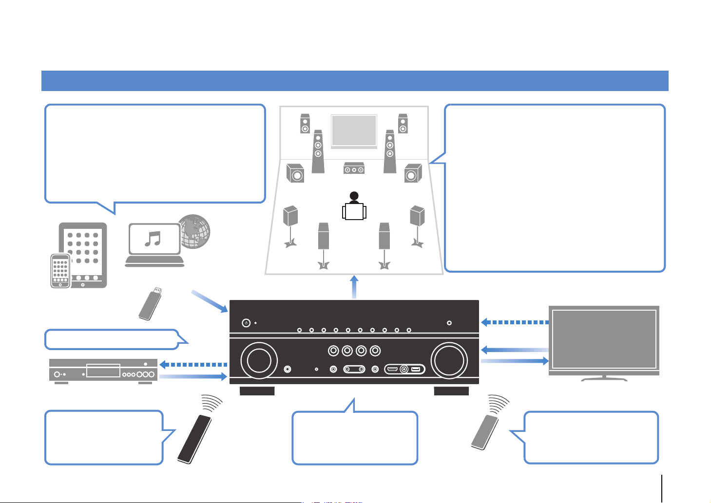
What you can do with the unit
Wide variety of supported content
• iPod/iPhone/iPad
•USB
• Media server (PC/NAS)
• Internet radio
•AirPlay
Network contents
iPod/iPhone/iPad
USB device
3D and 4K signals supported
HDMI Control
BD/DVD player
Audio/Video
. p.58
. p.62
. p.65
. p.68
. p.70
Audio
Speakers
Audio
AV receiver (the unit)
Supports 2- to 7.1-channel (plus presence)
speaker system. Allows you to enjoy your favorite
acoustic spaces in various styles.
• Automatically optimizing the speaker
. p.37
settings to suit your room (YPAO)
• Reproducing stereo or multichannel
. p.48
sounds with the sound fields like
actual movie theaters and concert halls
(CINEMA DSP)
• Enjoying compressed music with
. p.52
enhanced sound (Compressed Music
Enhancer)
• Playing back music in multiple rooms
. p.72
(multi-zone)
HDMI Control
Audio
Video
TV
Operating external
devices with the supplied
remote control
. p.108
The unit’s
remote control
Change the input source
and favorite settings with
one touch (SCENE)
. p.46
Sequential operation of a TV,
AV receiver, and BD/DVD
player (HDMI Control)
TV remote control
. p.124
FEATURES ➤ What you can do with the unit En 6
Page 7

Full of useful functions!
Useful tips
❑ Connecting various devices (p.28)
A number of HDMI jacks and various input/output jacks
on the unit allow you to connect video devices (such as
BD/DVD players), audio devices (such as CD players),
game consoles, camcorders, and other devices.
BD/DVD
player
Game
console
Camcorder
Set-top box
CD player
TV
❑ Playing back TV audio in surround sound
with a single HDMI cable connection
(Audio Return Channel: ARC) (p.23)
When using an ARC -compatible TV, you only need one
HDMI cable to enable video output to the TV, audio
input from the TV, and the transmission of HDMI Control
signals.
HDMI Control
TV audio
Video from
external device
❑ Creating 3-dimensional sound fields (p.48)
Connecting presence speakers allows you to create a
natural 3-dimensional sound field in your own room
(CINEMA DSP 3D). Even when no presence speakers
are connected, the Virtual Presence Speaker (VPS)
function produces 3D surround sound.
❑ Listening to FM/AM radio (p.53)
The unit is equipped with a built-in FM/AM tuner. You
can register up to 40 favorite radio stations as presets.
❑ Enjoying pure high fidelity sound (p.51)
When the Pure Direct mode is enabled, the unit plays
back the selected source with the least circuitry, which
lets you to enjoy Hi-Fi sound quality.
❑ Easy operation with a TV screen
You can navigate through different types of content
(such as iPod, USB, and network), view information, or
easily configure the settings using the on-screen menu.
❑ Low power consumption
The ECO mode (power saving function) reduces the
unit’s power consumption (p.102).
The combination of video/audio input jacks does not
match an external device...
Use “Audio In” in the “Input” menu to change the
combination of video/audio input jacks so that it matches
the output jack(s) of your external device (p.29).
Video and audio are not synchronized...
Use “Lipsync” in the “Setup” menu to adjust the delay
between video and audio output (p.94).
I want to hear audio from the TV speakers...
Use “Audio Output” in the “Setup” menu to select the
output destination of signals input into the unit (p.97).
Your TV speakers may be selected as an output
destination.
I want to change the on-screen menu language...
Use “Language” in the “Setup” menu to select a
language from English, Japanese, French, German,
Spanish, Russian and Chinese (p.36).
I want to update the firmware...
Use “UPDATE” in the “ADVANCED SETUP” menu to
update the unit’s firmware (p.107). If the unit is
connected to the Internet, a message will be displayed
on the TV when a firmware update is available (p.111).
Many other settings are available that let you to
customize the unit. For details, see the following pages.
• Input settings (p.81)
• Scene settings (p.84)
• Sound program and surround decoder settings (p.86)
• Various function settings (p.89)
• Information view (such as audio signal and video
signal) (p.104)
• System settings (p.105)
FEATURES ➤ What you can do with the unit En 7
Page 8

Part names and functions
Front panel (HTR-7065)
:9 B2 34561 78 A
MAIN ZONE
C
1 MAIN ZONE z key
Turns on/off (standby) the unit.
2 Standby indicator
Lights up when the unit is in standby mode under any of the
following conditions.
• HDMI Control is enabled (p.96)
• Standby Through is enabled (p.97)
• Network Standby is enabled (p.98)
• An iPod is being charged (p.58)
3 ZONE 2 key
Enables/disables the audio output to Zone2 (p.75).
4 ZONE CONTROL key
Changes the zone (main zone or the Zone2) that is controlled
by the keys and knobs on the front panel (p.75).
5 INFO key
Selects the information displayed on the front display (p.77).
6 MEMORY key
Registers FM/AM radio stations as preset stations (p.54).
7 PRESET keys
Select a preset FM/AM radio station (p.54).
PURE DIRECT
MEMORY
PRESET
ZONE CONTROL
INFOZONE 2
INPUT
PHONES
SILENT
CINEMA
YPAO MIC
TONE
BD
DVD
CONTROL
SCENE
TV
PROGRAM
FM AM
RADIO
NET
STRAIGHT
EDHIJKG
8 FM and AM keys
Switch between FM and AM (p.53).
9 Front display
Displays information (p.10).
0 Remote control sensor
Receives remote control signals (p.5).
A TUNING keys
Select the radio frequency (p.53).
B PURE DIRECT key
Enables/disables Pure Direct (p.51).
C INPUT knob
Selects an input source.
D PHONES jack
For connecting headphones.
E YPAO MIC jack
For connecting the supplied YPAO microphone (p.37).
F TONE CONTROL key
Adjusts the high-frequency range and low-frequency range
of output sounds (p.79).
AUX USB
VIDEO
HDMI IN
TUNING
VOLUME
VIDEO
iPod/iPhone/iPad
5V 2.1A
LF
G SCENE keys
Select the registered input source, sound program, and
various settings with one touch. Also, turns on the unit when
it is in standby mode (p.46).
H PROGRAM keys
Select a sound program or a surround decoder (p.47).
I STRAIGHT key
Enables/disables the straight decode mode (p.50).
J VIDEO AUX (HDMI IN) jack
For connecting a device, such as a camcorder and a game
console (p.31).
K USB jack
For connecting a USB storage device (p.62) or an iPod
(p.58).
VIDEO jack
For inputting video when “USB” is selected as the input
source (p.58).
L VOLUME knob
Adjusts the volume.
FEATURES ➤ Part names and functions En 8
Page 9

Front panel (HTR-6065)
MAIN ZONE
PHONES
SILENT
CINEMA
D
1 MAIN ZONE z key
Turns on/off (standby) the unit.
2 Standby indicator
Lights up when the unit is in standby mode under any of the
following conditions.
• HDMI Control is enabled (p.96)
• Standby Through is enabled (p.97)
• Network Standby is enabled (p.98)
• An iPod is being charged (p.58)
3 YPAO MIC jack
For connecting the supplied YPAO microphone (p.37).
4 ZONE 2 key
Enables/disables the audio output to Zone2 (p.75).
5 Remote control sensor
Receives remote control signals (p.5).
6 ZONE CONTROL key
Changes the zone (main zone or the Zone2) that is controlled
by the keys and knobs on the front panel (p.75).
7 INFO key
Selects the information displayed on the front display (p.77).
YPAO MIC
5A C3 46781 2 9:
MEMORY
PRESET
ZONE CONTROL
INPUT
INFOZONE 2
SCENE
BD
TV
DVD
CONTROL
TONE
PROGRAM
FM AM
RADIO
NET
STRAIGHT
AUX USB
VIDEO
HDMI IN
B
TUNING
FHIJKEG
8 MEMORY key
Registers FM/AM radio stations as preset stations (p.54).
9 PRESET keys
Select a preset FM/AM radio station (p.54).
0 FM and AM keys
Switch between FM and AM (p.53).
A Front display
Displays information (p.10).
B TUNING keys
Select the radio frequency (p.53).
C PURE DIRECT key
Enables/disables Pure Direct (p.51).
D PHONES jack
For connecting headphones.
E INPUT keys
Select an input source.
F TONE CONTROL key
Adjusts the high-frequency range and low-frequency range
of output sounds (p.79).
PURE DIRECT
VOLUME
iPod/iPhone/iPad
VIDEO
5V 2.1A
L
G SCENE keys
Select the registered input source, sound program, and
various settings with one touch. Also, turns on the unit when
it is in standby mode (p.46).
H PROGRAM keys
Select a sound program or a surround decoder (p.47).
I STRAIGHT key
Enables/disables the straight decode mode (p.50).
J VIDEO AUX (HDMI IN) jack
For connecting a device, such as a camcorder and a game
console (p.31).
K USB jack
For connecting a USB storage device (p.62) or an iPod
(p.58).
VIDEO jack
For inputting video when “USB” is selected as the input
source (p.58).
L VOLUME knob
Adjusts the volume.
FEATURES ➤ Part names and functions En 9
Page 10

Front display (indicators)
1 623 4 7 98:5
OUT 1 2
A AB C
1 HDMI
Lights up when HDMI signals are being input or output.
OUT1/OUT2 (HTR-7065 only)
Indicates the HDMI OUT jacks currently outputting an HDMI
signal
OUT (HTR-6065 only)
Lights up when HDMI signals are being output.
2 CINEMA DSP
Lights up when CINEMA DSP (p.48) is working.
CINEMA DSP n
Lights up when CINEMA DSP 3D (p.50) is working.
3 ENHANCER
Lights up when Compressed Music Enhancer (p.52) is
working.
4 ADAPTIVE DRC
Lights up when Adaptive DRC (p.79) is working.
5 STEREO
Lights up when the unit is receiving a stereo FM radio signal.
TUNED
Lights up when the unit is receiving an FM/AM radio station
signal.
ENHANCER
ADAPTIVE DRC
STEREO
3
TUNED
PA RT Y
6 PARTY (HTR-7065 only)
Lights up when the unit is in the party mode. (p.76)
7 SLEEP
Lights up when the sleep timer is on.
8 ZONE2
Lights up when audio output to Zone2 is enabled (p.75).
9 MUTE
Blinks when audio is muted.
0 Volume indicator
Indicates the current volume.
A Cursor indicators
Indicate the remote control cursor keys currently operational.
B Information display
Displays the current status (such as input name and sound
mode name). You can switch the information by pressing
INFO (p.77).
SLEEP
ZONE
2
VOL.
MUTE
C Speaker indicators
Indicate speaker terminals from which signals are output.
A Front speaker (L)
S Front speaker (R)
D Center speaker
F Surround speaker (L)
G Surround speaker (R)
H Surround back speaker (L)
J Surround back speaker (R)
K Surround back speaker
Z Presence speaker (L)
X Presence speaker (R)
L Subwoofer
SW
PL PR
C
LR
SL SR
SBL SB SBR
FEATURES ➤ Part names and functions En 10
Page 11

Rear panel (HTR-7065)
12
VIDEO
(TV)
31
4
OUT
HDMI
ARC
ANTENNA
(
)
RADIO
AM
AV
OUT
AV 6
2 5
NETWORKDC OUT
(
)
NET
5V
0.5A
COMPONENT
VIDEO
PR
PB
Y
OPTICAL OPTICAL
COAXIAL COAXIAL
AV 1 AV 2 AV 3 AV 4 AV 5
8
1 DC OUT jack
For connecting to an optional accessory.
2 NETWORK jack
For connecting to a network (p.32).
3 HDMI OUT 1–2 jacks
For connecting to HDMI-compatible TVs and outputting
video/audio signals (p.23). When using ARC, TV audio signal
can also be input through the HDMI OUT 1 jack.
4 ANTENNA jacks
For connecting to FM and AM antennas (p.32).
5 HDMI 1–5 jacks
For connecting to HDMI-compatible playback devices and
inputting video/audio signals (p.28).
6 SPEAKERS terminals
For connecting to speakers (p.19).
7 Power cabl e
For connecting to an AC wall outlet (p.35).
HDMI 1
(
)
BD/DVD
COMPONENT
VIDEO
FM
P
R
PB
VIDEO
Y
MONITOR OUT
AUDIO 1 AUDIO 2
: D E FC
AB9
6
HDMI 4 HDMI 5HDMI 3HDMI 2
SPEAKERS
SINGLE CENTER
SURROUND SUR. BACK
PRE OUT
SURROUND BACK/BI AMP
SUBWOOFER
12
SINGLE
REMOTE
IN
OUT
TRIGGER OUT
FRONT CENTER SURROUND
12V
0.1A
ZONE 2
FRONT
OUT
AUDIO
OUT
8 AV 1–6 jacks
For connecting to video/audio playback devices and
inputting video/audio signals (p.28).
9 AV OUT jacks
For outputting video/audio to a recording device (such as a
VCR) (p.33).
0 AUDIO 1–2 jacks
For connecting to audio playback devices and inputting
audio signals (p.31).
A MONITOR OUT jacks
COMPONENT VIDEO jacks
For connecting to a TV that supports component video and
outputting video signals (p.27).
VIDEO jack
For connecting to a TV that supports composite video and
outputting video signals (p.27).
ZONE 2/PRESENCE
EXTRA SP
7
* The area around the video/audio output jacks is
marked in white on the actual product to
prevent improper connections.
B REMOTE IN/OUT jacks
For connecting to a Yamaha product that supports SCENE
link playback (p.34) or for connecting to an infrared signal
receiver/emitter that allows you to operate the unit and other
devices from another room (p.74).
C TRIGGER OUT jack
For connecting to a device that supports the trigger function
(p.34).
D AU DIO OU T jacks
For outputting audio to a recording device (such as tape
deck) (p.33).
E ZONE2 OUT jacks
For connecting to the external amplifier used in Zone2 and
for outputting audio (p.73).
F PRE OUT jacks
For connecting to a subwoofer with built-in amplifier or to an
external power amplifier (p.33).
FEATURES ➤ Part names and functions En 11
Page 12

Rear panel (HTR-6065)
2 5
NETWORKDC OUT
(
NET
5V
0.5A
COMPONENT
VIDEO
P
R
P
B
Y
OPTICAL OPTICAL
COAXIAL COAXIAL
AV 1 AV 2 AV 3 AV 4 AV 5
31
4
OUT
HDMI
)
ARC
ANTENNA
(
)
RADIO
AM
VIDEO
(TV)
AV
OUT
AV 6
8
1 DC OUT jack
For connecting to an optional accessory.
2 NETWORK jack
For connecting to a network (p.32).
3 HDMI OUT jack
For connecting to an HDMI-compatible TV and outputting
video/audio signals (p.23). When using ARC, TV audio signal
can also be input through the HDMI OUT jack.
4 ANTENNA jacks
For connecting to FM and AM antennas (p.32).
5 HDMI 1–5 jacks
For connecting to HDMI-compatible playback devices and
inputting video/audio signals (p.28).
6 SPEAKERS terminals
For connecting to speakers (p.19).
7 Power cabl e
For connecting to an AC wall outlet (p.35).
HDMI 1
(
)
BD/DVD
COMPONENT
VIDEO
FM
P
R
P
B
VIDEO
Y
MONITOR OUT
AUDIO 1 AUDIO 2
: D E FC
AB9
6
HDMI 4 HDMI 5HDMI 3HDMI 2
SPEAKERS
REMOTE
IN
OUT
TRIGGER OUT
FRONT CENTER SURROUND
12V
0.1A
AUDIO
ZONE 2
OUT
OUT
8 AV 1–6 jacks
For connecting to video/audio playback devices and
inputting video/audio signals (p.28).
9 AV OUT jacks
For outputting video/audio to a recording device (such as a
VCR) (p.33).
0 AUDIO 1–2 jacks
For connecting to audio playback devices and inputting
audio signals (p.31).
A MONITOR OUT jacks
COMPONENT VIDEO jacks
For connecting to a TV that supports component video and
outputting video signals (p.27).
VIDEO jack
For connecting to a TV that supports composite video and
outputting video signals (p.27).
SURROUND BACK/BI-AMP
1
2
SUBWOOFER
ZONE 2/PRESENCE
SINGLE
EXTRA SP
7
* The area around the video/audio output jacks is
marked in white on the actual product to prevent
improper connections.
B REMOTE IN/OUT jacks
For connecting to a Yamaha product that supports SCENE
link playback (p.34) or for connecting to an infrared signal
receiver/emitter that allows you to operate the unit and other
devices from another room (p.74).
C TRIGGER OUT jack
For connecting to a device that supports the trigger function
(p.34).
D AU DIO OU T jacks
For outputting audio to a recording device (such as tape
deck) (p.33).
E ZONE2 OUT jacks
For connecting to the external amplifier used in Zone2 and
for outputting audio (p.73).
F SUBWOOFER 1–2 jacks
For connecting to a subwoofer with built-in amplifier (p.33).
FEATURES ➤ Part names and functions En 12
Page 13

Remote control
1
2
3
4
5
6
7
8
9
:
A
B
C
D
E
F
RECEIVER
SOURCE
HDMI
123 4
5
AV
12
65
USB
TUNER
MAIN
BD
DVD
PROGRAM VOLUME
ON
SCREEN
MODE
MOVIE
INFO SLEEP
123 4
5
90
INPUT
MUTE
NET
PARTY HDMI OUT
ZONE 2
SCENE
TV
NET
MUTE
TOP MENU
ENTER
TUNING PRESET
SUR. DECODE
MUSIC
ENHANCER
6 87
MEMORY
TV
TV VOL TV CH
(HTR-7065)
V-AUX
3 4
AUDIO
12
RADIO
POP-UP/MENU
OPTION
DISPLAYRETURN
BAND
STRAIGHT
PURE DIRECT
ENT
10
CODE SET
G
H
I
J
K
L
M
1 Remote control signal transmitter
Transmits infrared signals.
2 SOURCE z key
Turns on/off an external device.
SOURCE key
Sets the remote control to operate external devices (p.109).
This key lights up in green after pressed.
RECEIVER key
Sets the remote control to operate the unit (p.109). This key
lights up in orange after pressed.
RECEIVER z key
Turns on/off (standby) the unit.
3 Input selection keys
Select an input source for playback.
HDMI 1–5 HDMI 1–5 jacks
V-A UX VIDEO AUX jack (on the front panel)
AV 1 – 6 AV 1–6 jacks
AUDIO 1–2 AUDIO 1–2 jacks
TUNER FM/AM radio
USB USB jack (on the front panel)
NET NETWORK jack (press repeatedly to select a
desired network source)
★ Changes the external device to be controlled
without switching the input source.
4 MAIN/ZONE2 switch
Changes the zone (main zone or Zone2) that is controlled by
the remote control (p.75).
5 SCENE keys
Select the registered input source, sound program, and
various settings with one touch. Also, turns on the unit when
it is in standby mode (p.46).
6 PROGRAM keys
Select a sound program (p.47).
7 External device operation keys
Select menus for external devices (p.109).
8 ON SCREEN key
Displays the on-screen menu on the TV.
9 Menu operation keys
Cursor keys Select a menu or a parameter.
ENTER Confirms a selected item.
RETURN Returns to the previous screen.
0 MODE key
Switches the iPod operation modes (p.60).
A Radio keys
Operate the FM/AM radio when “TUNER” is selected as the
input source (p.53).
BAND Switches between FM and AM radio
PRESET Select a preset station.
TUNING Select the radio frequency.
External device operation keys
Let you play back and perform other operations for external
devices when an input source other than “TUNER” is
selected (p.109).
B Sound mode keys
Select a sound mode (p.47).
C INFO key
Selects the information displayed on the front display (p.77).
D SLEEP key
Switches the unit to standby mode automatically after a
specified period of time has elapsed (sleep timer). Press
repeatedly to set the time (120 min, 90 min, 60 min, 30 min, off).
E Numeric keys
Let you enter numerical values, such as radio frequencies.
MEMORY key
Registers FM/AM radio stations as presets (p.54).
F TV operation keys
Let you select TV input and volume, and perform other TV
operations (p.108).
G HDMI OUT key (HTR-7065 only)
Selects HDMI OUT jacks to be used for video/audio output
(p.45).
H PARTY key (HTR-7065 only)
Turns on/off the party mode (p.76).
I VOLUME keys
Adjust the volume.
J MUTE key
Mutes the audio output.
K OPTION key
Displays the option menu (p.78).
L DISPLAY key
Displays status information on the TV (p.77).
M CODE SET key
Registers remote control codes of external devices on the
remote control (p.108).
• To operate external devices with the remote control, register a
remote control code for each device before using (p.108).
FEATURES ➤ Part names and functions En 13
Page 14

PREPARATIONS
General setup procedure
1 Placing speakers (p.15)
2 Connecting speakers (p.19)
3 Connecting a TV (p.23)
4 Connecting playback devices (p.28)
5 Connecting the FM/AM antennas (p.32)
6 Connecting to a network (p.32)
7 Connecting other devices (p.33)
8 Connecting the power cable (p.35)
Selecting an on-screen menu language
9
(p.36)
Optimizing the speaker settings
10
automatically (YPAO) (p.37)
Select the speaker layout for the number of speakers that you are using and place them in your room.
Connect the speakers to the unit.
Connect a TV to the unit.
Connect video devices (such as BD/DVD players) and audio devices (such as CD players) to the unit.
Connect the supplied FM/AM antennas to the unit.
Connect the unit to a network.
Connect external devices, such as an external power amplifier (HTR-7065 only) and recording devices.
After all the connections are complete, plug in the power cable.
Select the desired on-screen menu language (default: English).
Optimize the speaker settings, such as volume balance and acoustic parameters, to suit your room
(YPAO).
This completes all the preparations. Enjoy playing movies, music, radio and other content with the unit!
PREPARATIONS ➤ General setup procedure En 14
Page 15

Speaker placement
1
2 3 4 5 6 7 8 9 10
1 Placing speakers
Select the speaker layout for the number of speakers that you are using and place the speakers and subwoofer (with built-in amplifier) in your room. This section describes the
representative speaker layout examples.
Caution
• Under its default settings, the unit is configured for 8-ohm speakers. When connecting 6-ohm speakers, set the unit’s speaker impedance to “6 Ω MIN”. In this case, you can also use 4-ohm speakers as the front speakers.
For details, see “Setting the speaker impedance” (p.18).
Speaker type Abbr. Function
Front (L) 1
Front (R) 2 ● ●●●●●●●
Center 3 Produces center channel sounds (such as movie dialogue and vocals). ●●●●● ●
Surround (L) 4
Surround (R) 5 ● ●●●●●
Surround back (L) 6
Surround back (R) 7 ●●
Surround back 8 Produces sounds mixed from surround back left/right channel sounds. ●
Presence (L) Q
Presence (R) W ●●
Subwoofer 9
• For information on the ideal speaker layout, see “Ideal speaker layout” (p.119).
• If you have seven speakers, use two of them as surround back speakers or presence speakers.
To reinforce the rear right/left sounds, use them as surround back speakers.
To create a natural 3-dimensional sound field, use them as presence speakers.
• Two subwoofers connected to the unit output the same sounds.
Produce front right/left channel sounds (stereo sounds).
Produce surround right/left channel sounds. Surround speakers also produce surround back channel sounds when
no surround back speakers are connected.
Produce surround back left/right channel sounds.
Produce CINEMA DSP effect sounds. In combination with CINEMA DSP 3D (p.50), the presence speakers create a
natural 3-dimensional sound field in your room.
Produces LFE (low-frequency effect) channel sounds and reinforces the bass parts of other channels.
This channel is counted as “0.1”. You can connect 2 subwoofers (with built-in amplifier) to the unit.
Speaker system (the number of channels)
7.1+2 7.1 7.1 6.1 5.1 4.1 3.1 2.1
● ●●●●●●●
● ●●●●●
●●
●●
● ●●●●●●●
PREPARATIONS ➤ Placing speakers En 15
Page 16

Speaker placement
1
2 3 4 5 6 7 8 9 10
7.1+2-channel system
QW
1
45
67
• The surround back speakers and presence speakers do not produce sounds simultaneously. The unit
automatically changes the speakers to be used, depending on the selected CINEMA DSP (p.48).
2
39
9
7.1-channel system (using presence speakers)
QW
1
2
7.1-channel system (using surround back speakers)
1
45
67
2
39
6.1-channel system
1
2
39
45
39
45
8
PREPARATIONS ➤ Placing speakers En 16
Page 17

Speaker placement
1
2 3 4 5 6 7 8 9 10
5.1-channel system
45
4.1-channel system
12
39
12
3.1-channel system
12
39
2.1-channel system
12
9
45
9
PREPARATIONS ➤ Placing speakers En 17
Page 18

Speaker placement
1
2 3 4 5 6 7 8 9 10
■ Setting the speaker impedance
Under its default settings, the unit is configured for 8-ohm speakers. When connecting
6-ohm speakers, set the speaker impedance to “6 Ω MIN”. In this case, you can also
use 4-ohm speakers as the front speakers.
Before connecting speakers, connect the power cable to an AC wall
1
outlet.
While holding down STRAIGHT on the front panel, press
2
MAIN ZONE z.
MAIN ZONE z
STRAIGHT
Check that “SP IMP.” is displayed on the front display.
3
SPIMP.8MIN
Press STRAIGHT to select “6 Ω MIN”.
4
Press MAIN ZONE z to set the unit to standby mode and remove the
5
power cable from the AC wall outlet.
You are now ready to connect the speakers.
PREPARATIONS ➤ Placing speakers En 18
Page 19

FRONT CENTER SURROUND
SINGLE
SURROUND BACK/BI AMP
ZONE 2/PRESENCE
EXTRA SP
AUDIO
OUT
ZONE 2
OUT
FRONT
SURROUND SUR. BACK
PRE OUT
SINGLE CENTER
SUBWOOFER
12
SPEAKERS
FRONT CENTER SURROUND
SINGLE
SURROUND BACK/BI AMP
ZONE 2/PRESENCE
EXTRA SP
AUDIO
OUT
ZONE 2
OUT
FRONT
SURROUND SUR. BACK
PRE OUT
SINGLE CENTER
SUBWOOFER
12
SPEAKERS
Speaker connections
1 2
3 4 5 6 7 8 9 10
2 Connecting speakers
Connect the speakers placed in your room to the unit.
The following diagrams provide connections for 7.1+2-,
7.1-, and 6.1-channel systems as examples. For other
systems, connect speakers while referring to the
connection diagram for the 6.1-channel system.
Caution
• Remove the unit’s power cable from an AC wall outlet and turn
off the subwoofer before connecting the speakers.
• Ensure that the core wires of the speaker cable do not touch
one another or come into contact with the unit’s metal parts.
Doing so may damage the unit or the speakers. If the speaker
cables short circuit, “Check SP Wires” will appear on the front
display when the unit is turned on.
• The illustrations of the unit (rear) used in this section are of the
HTR-7065.
Cables required for connection
(commercially available)
Speaker cables (x the number of speakers)
+
–
+
–
Audio pin cable (two for connecting two subwoofers)
7.1+2-channel system 7.1-channel system
(using surround back speakers)
The unit (rear)
QW
1
9
3
2
9
45
67
The unit (rear)
1
9
3
45
67
2
PREPARATIONS ➤ Connecting speakers En 19
Page 20

FRONT CENTER SURROUND
SINGLE
SURROUND BACK/BI AMP
ZONE 2/PRESENCE
EXTRA SP
AUDIO
OUT
ZONE 2
OUT
FRONT
SURROUND SUR. BACK
PRE OUT
SINGLE CENTER
SUBWOOFER
12
SPEAKERS
FRONT CENTER SURROUND
SINGLE
SURROUND BACK/BI AMP
ZONE 2/PRESENCE
EXTRA SP
AUDIO
OUT
ZONE 2
OUT
FRONT
SURROUND SUR. BACK
PRE OUT
SINGLE CENTER
SUBWOOFER
12
SPEAKERS
FRONT
FRONT
Speaker connections
1 2
3 4 5 6 7 8 9 10
7.1-channel system
6.1-channel system
(using presence speakers)
The unit (rear)
QW
12
9
45
3
■ Connecting speaker cables
Speaker cables have two wires. One is for connecting
the negative (-) terminal of the unit and the speaker, and
The unit (rear)
12
9
3
45
8
the other is for the positive (+) terminal. If the wires are
colored to prevent confusion, connect the black wire to
the negative and the other wire to the positive terminal.
a Remove approximately 10 mm (3/8”) of insulation from
the ends of the speaker cable and twist the bare wires of
the cable firmly together.
b Loosen the speaker terminal.
c Insert the bare wires of the cable into the gap on the side
(upper right or bottom left) of the terminal.
d Tighten the terminal.
+ (red)
c
b
d
- (black)
Using a banana plug
(U.S.A. and Australia models only)
a Tighten the speaker terminal.
b Insert a banana plug into the end of the terminal.
Banana plug
a
aa
b
When using only one surround back speaker, connect it
to the SINGLE jack (L side).
PREPARATIONS ➤ Connecting speakers En 20
Page 21

E
2/
FRONT CENTER SURROUND
SINGLE
SURROUND BACK/BI AMP
ZONE 2/PRESENCE
EXTRA SP
AUDIO
OUT
ZONE 2
OUT
FRONT
SURROUND SUR. BACK
PRE OUT
SINGLE CENTER
SUBWOOFER
12
SPEAKERS
Speaker connections
1 2
3 4 5 6 7 8 9 10
Push-type speaker terminals
(HTR-6065 only)
a Remove approximately 10 mm (3/8”) of insulation from
the ends of the speaker cable, and twist the bare wires of
the cable firmly together.
b Press down the tab.
c Insert the bare wires of the cable into the hole in the
terminal.
d Release the tab.
PRESENCE
EXTRA
aa
d
SP
b
+ (red)
c
- (black)
■ Connecting the subwoofer
Use an audio pin cable to connect the subwoofer.
Audio pin cable
Connecting front speakers that support bi-amp connections
When using front speakers that support bi-amp
connections, connect them to the FRONT jacks and
SURROUND BACK/BI-AMP jacks.
To enable the bi-amp function, set “Power Amp Assign”
(p.91) in the “Setup” menu to “5ch BI-AMP” after
connecting the power cable to an AC wall outlet.
The unit (rear)
12
3
9
Caution
• Before making bi-amp connections, remove any brackets or
cables that connect a woofer with a tweeter. Refer to the
instruction manual of the speakers for details. If you are not
making bi-amp connections, make sure that the brackets or
cables are connected before connecting the speaker cables.
• Surround back speakers cannot be used during bi-amp
connections.
45
PREPARATIONS ➤ Connecting speakers En 21
Page 22

Input/output jacks and cables
■ Video/audio jacks
❑ HDMI jacks
Transmit digital video and digital sound through a single
jack. Use an HDMI cable.
HDMI cable
• Use a 19-pin HDMI cable with the HDMI logo. We recommend using
a cable less than 5.0 m (16.4 ft) long to prevent signal quality
degradation.
• To connect a device that has a DVI jack, an HDMI/DVI-D cable is
required.
• The unit’s HDMI jacks support the HDMI Control, Audio Return
Channel (ARC), and 3D and 4K video transmission features.
• Use high speed HDMI cables to enjoy 3D or 4K videos.
■ Video jacks
❑ COMPONENT VIDEO jacks
Transmit video signals separated into three
components: luminance (Y), chrominance blue (P
and chrominance red (P
R). Use a component video
cable with three plugs.
Component video cable
❑ VIDEO jacks
Transmit analog video signals. Use a video pin cable.
Video pin cable
B),
■ Audio jacks
❑ OPTICAL jacks
Transmit digital audio signals. Use a digital optical
cable. Remove the tip protector (if available) before
using the cable.
Digital optical cable
OPTICAL
)
(
TV
AV 4
❑ COAXIAL jacks
Transmit digital audio signals. Use a digital coaxial
cable.
Digital coaxial cable
❑ AUDIO jacks
Transmit analog stereo audio signals. Use a stereo pin
cable.
Stereo pin cable
PREPARATIONS ➤ Input/output jacks and cables En 22
Page 23

1 2 3
TV connection
4 5 6 7 8 9 10
3 Connecting a TV
Connect a TV to the unit so that video input to the unit can be output to the TV.
You can also enjoy playback of TV audio on the unit.
The connection method varies depending on the functions and video input jacks
available on your TV.
Refer to the instruction manual of the TV and choose a connection method.
Does your TV support
Audio Return Channel (ARC)?
Yes
■ Connection Method 1 (p.23)
No
Does your TV support
HDMI Control?
Yes
■ Connection Method 2 (p.25)
No
Does your TV have an
HDMI input jack?
Yes
■ Connection Method 3 (p.26)
No
■ Connection Method 4 (p.27)
About HDMI Control
HDMI Control allows you to operate external devices via HDMI. If you connect a TV
that supports HDMI Control to the unit with an HDMI cable, you can control the unit’s
power and volume with the TV’s remote control. You can also control playback
devices (such as an HDMI Control-compatible BD/DVD player) connected to the
unit with an HDMI cable. For details, see “HDMI Control” (p.124).
About Audio Return Channel (ARC)
ARC allows audio signals to travel both ways under HDMI Control. If you connect a
TV that supports HDMI Control and ARC to the unit with a single HDMI cable, you
can output video/audio to the TV or input TV audio to the unit.
■
Connection Method 1 (HDMI Control/ARC-compatible TV)
Connect the TV to the unit with an HDMI cable.
• The following explanation is based on the assumption that you have not changed the “HDMI” parameters
(p.96) in the “Setup” menu.
• (HTR-7065 only)
HDMI Control is available only on the HDMI OUT 1 jack.
HDMI OUT (ARC) jack
OUT
The unit
(rear)
5V
0.5A
COMPONENT
VIDEO
P
R
P
B
Y
OPTICAL OPTICAL
AV 1AV 2AV 3 AV 4 AV 5
• By connecting a TV to the unit with an HDMI cable, any video input to the unit can be output to the TV
(except some component video signals), regardless of the method used to connect the video device to the
unit. For details, see “Video signal flow” (p.123).
• By connecting a TV to the unit with an HDMI cable, you can navigate the iPod, USB storage device and
network sources, or configure the settings of the unit with the menu displayed on the TV.
• (HTR-7065 only)
You can connect another TV or a projector by using the HDMI OUT 2 jack (p.27).
HDMI
12
ARC
NETWORKDC OUT
(
)
NET
COAXIAL COAXIAL
VIDEO
(TV)
HDMI
12
ARC
HDMI
OUT
ANTENNA
(
)
RADIO
AM
AV
OUT
AV 6
HDMI input
(ARC-compatible)
HDMI
ARC
HDMI
TV
PREPARATIONS ➤ Connecting a TV En 23
Page 24

D
A
Y
O
N
1 2 3
TV connection
4 5 6 7 8 9 10
❑ Necessary settings
To use HDMI Control and ARC, you need to configure the following settings.
For details on settings and operating your TV, refer to the instruction manual for the TV.
After connecting external devices (such as a TV and playback devices)
1
and the power cable to the unit, turn on the unit, TV, and playback devices.
Configure the settings of the unit.
2
a Check that ARC is enabled on the TV.
b Switch the TV input to display video from the unit.
c Press ON SCREEN.
ON
SCREEN
RETURN
d Use the cursor keys to select “Setup” and press ENTER.
ENTER
OPTION
DISPLAYRETURN
ISPL
PTIO
ON SCREEN
Cursor keys
ENTER
Configure the settings for HDMI Control.
3
a Enable HDMI Control on the TV and playback devices (such as HDMI
Control-compatible BD/DVD player).
b Turn off the TV’s main power and then turn off the unit and playback devices.
c Turn on the unit and playback devices and then turn on the TV’s main power.
d Switch the TV input to display video from the unit.
e Check the following.
On the unit: The input to which the playback device is connected is selected. If not,
select the input source manually.
On the TV: The video from the playback device is displayed.
f Check that the unit is properly synchronized with the TV by turning off the TV or
adjusting the TV volume with the TV remote control.
This completes the necessary settings.
If you select a TV program with the TV remote control, the input source of the unit will be
automatically switched to “AV 4” and the TV audio will be played back on the unit.
If you cannot hear the TV’s audio, check that “ARC” (p.97) in the “Setup” menu is set to
“On”.
• If HDMI Control does not work properly, try turning off and on (or unplugging and then plugging in again)
the devices. It may solve the problem.
• If the unit is not synchronized to the TV’s power operations, check the priority of the audio output setting on
the TV.
• If the audio is interrupted while using ARC, set “ARC” (p.97) in the “Setup” menu to “Off” and use a digital
optical cable to input TV audio to the unit (p.25).
e Use the cursor keys (e/r) to select “HDMI”.
• “AV 4” is set as TV audio input at the factory. If you have connected any external device to the AV 4 jacks,
use “TV Audio Input” (p.96) in the “Setup” menu to change the TV audio input assignment. To use the
SCENE function (p.46), you also need to change the input assignment for SCENE(TV).
f Use the cursor keys (q/w) to select “HDMI Control” and press ENTER.
g Use the cursor keys to select “On”.
h Press ON SCREEN.
PREPARATIONS ➤ Connecting a TV En 24
Page 25

D
A
Y
O
N
1 2 3
TV connection
4 5 6 7 8 9 10
■ Connection Method 2 (HDMI Control-compatible TV)
Connect the TV to the unit with an HDMI cable and a digital optical cable.
• The following explanation is based on the assumption that you have not changed the “HDMI” parameters
(p.96) in the “Setup” menu.
• (HTR-7065 only)
HDMI Control is available only on the HDMI OUT 1 jack.
HDMI OUT jack
OUT
The unit
(rear)
5V
0.5A
COMPONENT
VIDEO
P
R
P
B
Y
OPTICAL OPTICAL
AV 1AV 2AV 3 AV 4 AV 5
• By connecting a TV to the unit with an HDMI cable, any video input to the unit can be output to the TV
(except some component video signals), regardless of the method used to connect the video device to the
unit. For details, see “Video signal flow” (p.123).
• By connecting a TV to the unit with an HDMI cable, you can navigate the iPod, USB storage device and
network sources, or configure the settings of the unit with the menu displayed on the TV.
• (HTR-7065 only)
You can connect another TV or a projector by using the HDMI OUT 2 jack (p.27).
HDMI
12
ARC
NETWORKDC OUT
(
)
NET
COAXIAL COAXIAL
12
VIDEO
(TV)
HDMI
ARC
AV 4 (OPTICAL) jack Audio output
HDMI
OUT
ANTENNA
(
)
RADIO
AM
HDMI input
HDMI
HDMI
OPTICAL
AV
OUT
OO
TV
OPTICAL
(TV)
AV 6
AV 4
(digital optical)
❑ Necessary settings
To use HDMI Control, you need to configure the following settings.
For details on settings and operating your TV, refer to the instruction manual for the TV.
After connecting external devices (such as a TV and playback
1
devices) and power cable of the unit, turn on the unit, TV, and
playback devices.
Configure the settings of the unit.
2
a Switch the TV input to display video from the unit.
b Press ON SCREEN.
ON
SCREEN
RETURN
c Use the cursor keys to select “Setup” and press ENTER.
d Use the cursor keys (e/r) to select “HDMI”.
ENTER
DISPLAYRETURN
PTIO
OPTION
ISPL
ON SCREEN
Cursor keys
ENTER
e Use the cursor keys (q/w) to select “HDMI Control” and press ENTER.
f Use the cursor keys to select “On”.
g Press ON SCREEN.
PREPARATIONS ➤ Connecting a TV En 25
Page 26

1 2 3
TV connection
4 5 6 7 8 9 10
Configure the settings for HDMI Control.
3
a Enable HDMI Control on the TV and playback devices (such as a HDMI
Control-compatible BD/DVD player).
b Turn off the TV’s main power and then turn off the unit and playback devices.
c Turn on the unit and playback devices and then turn on the TV.
d Switch the TV input to display video from the unit.
e Check the following.
On the unit: The input to which the playback device is connected is selected. If not,
select the input source manually.
On the TV: The video from the playback device is displayed.
f Check that the unit is properly synchronized with the TV by turning off the TV or
adjusting the TV volume with the TV remote control.
This completes the necessary settings.
If you select a TV program with the TV remote control, the input source of the unit will be
automatically switched to “AV 4” and the TV audio will be played back on the unit.
• If HDMI Control does not work properly, try turning off and on (or unplugging and then plugging in again)
the devices. It may solve the problem.
• If the unit is not synchronized to the TV’s power operations, check the priority of the audio output setting on
the TV.
• “AV 4” is set as TV audio input at the factory. If you have connected any external device to the AV 4 jacks or
if you want to use another input jack (other than OPTICAL) for connecting the TV, use “TV Audio Input”
(p.96) in the “Setup” menu to change the TV audio input assignment. To use the SCENE function (p.46),
you also need to change the input assignment for SCENE(TV).
■ Connection Method 3 (TV with HDMI input jacks)
Connect the TV to the unit with an HDMI cable and a digital optical cable.
HDMI OUT jack
OUT
The unit
(rear)
5V
0.5A
COMPONENT
VIDEO
P
R
P
B
Y
OPTICAL OPTICAL
AV 1AV 2AV 3 AV 4 AV 5
If you switch the input source of the unit to “AV 4” using the AV 4 or SCENE(TV) keys,
the TV audio will be played back on the unit.
• By connecting a TV to the unit with an HDMI cable, any video input to the unit can be output to the TV
(except some component video signals), regardless of the method used to connect the video device to the
unit. For details, see “Video signal flow” (p.123).
• By connecting a TV to the unit with an HDMI cable, you can navigate the iPod, USB storage device and
network sources, or configure the settings of the unit with the menu displayed on the TV.
• If you have connected any external device to the AV 4 jacks or if you want to use another input jack (other
than OPTICAL) for connecting the TV, connect the TV to one of the AV 1–6 and AUDIO 1–2 jacks. To use
the SCENE function (p.46), you also need to change the input assignment for SCENE(TV).
• (HTR-7065 only)
You can connect another TV or a projector by using the HDMI OUT 2 jack (p.27).
HDMI
12
ARC
NETWORKDC OUT
(
)
NET
COAXIAL COAXIAL
VIDEO
(TV)
HDMI
12
ARC
AV 4 (OPTICAL) jack Audio output
HDMI
OUT
ANTENNA
(
)
RADIO
AM
HDMI input
HDMI
HDMI
OPTICAL
AV
OUT
OO
TV
AV 6
OPTICAL
(TV)
AV 4
(digital optical)
PREPARATIONS ➤ Connecting a TV En 26
Page 27

U
U
M
H
2
1 2 3
TV connection
4 5 6 7 8 9 10
■ Connection Method 4 (TV without HDMI input jacks)
When connecting any video device to the AV 1–2 (COMPONENT VIDEO) jacks of the
unit, connect the TV to the MONITOR OUT (COMPONENT VIDEO) jacks.
When connecting any video device to the AV 3–6 (VIDEO) jacks or the front VIDEO jack
of the unit, connect the TV to the MONITOR OUT (VIDEO) jack.
If you select “AV 4” as the input source by pressing AV 4 or SCENE(TV), the TV audio
will be played back on the unit.
• If you connect your TV to the unit with a cable other than HDMI, video input to the unit via HDMI cannot be
output to the TV.
• Operations with TV screen are available only when your TV is connected to the unit via HDMI.
• If you have connected any external device to the AV 4 jacks or if you want to use another input jack (other
than OPTICAL) for connecting the TV, connect the TV to one of the AV 1–6 and AUDIO 1–2 jacks. To use
the SCENE function (p.46), you also need to change the input assignment for SCENE(TV).
❑ COMPONENT VIDEO connection (with a component video cable)
Video input
(component video)
P
R
P
B
Y
OPTICAL
COMPONENT
VIDEO
P
R
P
B
Y
TV
The unit (rear)
OUT
HDMI
12
ARC
ANTENNA
(
RADIO
AM
VIDEO
OPTICAL
COAXIAL
(TV)
AV 3 AV 4 AV 5
OPTICAL
AV 6
(TV)
AV 4
AV 4 (OPTICAL) jack
MONITOR OUT
(COMPONENT VIDEO)
jacks
COMPONENT
HDMI 1
(
BD/DVD
)
FM
AV
OUT
AUDIO 1 AUDIO 2
VIDEO
HDMHDMI 2
)
COMPONENT
VIDEO
R
P
P
B
Y
MONITOR OUT
R
P
REMOT
P
B
IN
OUT
VIDEO
Y
MONITOR O
12V
TRIGGER O
R
P
P
B
Y
OO
Audio output
(digital optical)
❑ VIDEO (composite video) connection (with a video pin cable)
The unit (rear)
NETWORKDC OUT
(
NET
5V
0.5A
COMPONENT
VIDEO
P
R
P
B
Y
OPTICAL OPTICAL
COAXIAL COAXIAL
AV 1AV 2AV 3 AV 4 AV 5
)
VIDEO
(TV)
MONITOR OUT
(VIDEO) jack
HDMI 1
HDMI 2
(
)
OUT
HDMI
12
ARC
BD/DVD
VIDEO
ANTENNA
(
)
RADIO
COMPONENT
VIDEO
FM
AM
ITOR OUT
P
R
P
B
VIDEO
Y
MONITOR OUT
AV
OUT
AV 6
AUDIO 1 AUDIO 2
OPTICAL
(TV)
AV 4
V
RE
IN
OUT
1
TRIGG
OO
AV 4 (OPTICAL) jack Audio output
Video input
(composite video)
V
OPTICAL
(digital optical)
VIDEO
TV
■ Connecting another TV or a projector
(HTR-7065 only)
The unit has two HDMI output jacks. If you connect another TV or a projector to the unit
with an HDMI cable, you can switch the TV (or projector) to be used for watching
videos with the remote control (p.45).
HDMI OUT 2 jack
OUT
The unit
(rear)
12
NETWORKDC OUT
(
)
NET
5V
0.5A
COMPONENT
VIDEO
P
R
P
B
VIDEO
Y
OPTICAL OPTICAL
COAXIAL COAXIAL
AV 1AV 2AV 3 AV 4 AV 5
HDMI
ARC
OUT
HDMI
12
ARC
(TV)
HDMI
ANTENNA
(
)
RADIO
AM
AV
OUT
AV 6
TV (already connected)
HDMI
TV
HDMI
Projector
HDMI input
• HDMI Control is not available on the HDMI OUT 2 jack.
PREPARATIONS ➤ Connecting a TV En 27
Page 28

1 2 3 4
Playback device connections
5 6 7 8 9 10
4 Connecting playback devices
The unit is equipped with a variety of input jacks including HDMI input jacks to allow
you to connect different types of playback devices. For information on how to connect
an iPod or a USB storage device, see the following pages.
– Connecting an iPod (p.58)
– Connecting a USB storage device (p.62)
Connecting video devices (such as BD/DVD players)
Connect video devices such as BD/DVD players, set-top boxes (STBs) and game
consoles to the unit. Depending on the video/audio output jacks available on your video
device, choose one of the following connections. We recommend using an HDMI
connection if the video device has an HDMI output jack.
• If the combination of video/audio input jacks available on the unit does not match your video device, change
its combination according to the output jacks of your device (p.29).
■ HDMI connection
Connect a video device to the unit with an HDMI cable.
HDMI 1–5 jacks
HDMI 1
(
)
BD/DVD
The unit (rear)
12
VIDEO
OPTICAL
COAXIAL
(TV)
AV 3 AV 4 AV 5
HDMI 1
(
)
OUT
HDMI
BD/DVD
ARC
ANTENNA
(
)
RADIO
COMPONENT
VIDEO
FM
AM
R
P
P
B
Y
MONITOR OUT
AV
OUT
AV 6
AUDIO 1 AUDIO 2
HDMI 4 HDMI 5HDMI 3HDMI 2
FRONT CENTER
REMOTE
IN
OUT
VIDEO
12V
0.1A
TRIGGER OUT
AUDIO
ZONE 2
OUT
OUT
If you select the input source by pressing HDMI 1–5, the video/audio played back on
the video device will be output from the unit.
HDMI
HDMI 4 HDMI 5HDMI 3HDMI 2
HDMI output
HDMI
HDMI
Video device
■ Component video connection
Connect a video device to the unit with a component video cable and an audio cable
(digital optical or digital coaxial). Choose a set of input jacks (on the unit) depending on
the audio output jacks available on your video device.
Output jacks on video device
Video Audio
Component video
(COMPONENT VIDEO)
The unit (rear)
NETWORKDC OUT
(
NET
5V
0.5A
COMPONENT
VIDEO
P
R
P
B
Y
OPTICAL OPTICAL
COAXIAL COAXIAL
AV 1AV 2AV 3 AV 4 AV 5
AV 1–2
jacks
COMPONENT
VIDEO
R
P
OUT
HDMI
)
12
ARC
P
B
Y
VIDEO
(TV)
AV 6
OPTICAL COAXIAL
AV1 AV2
AV 1 (OPTICAL) jack or
AV 2 (COAXIAL) jack
Digital optical AV 1 (COMPONENT VIDEO + OPTICAL)
Digital coaxial AV 2 (COMPONENT VIDEO + COAXIAL)
(component video)
R
P
P
B
Y
O
OPTICAL
C
COAXIAL
Audio output
(digital optical or digital coaxial)
ANTENNA
AM
R
P
P
B
Y
(
)
RADIO
O
AV
OUT
C
If you select the input source by pressing AV 1–2, the video/audio played back on the
video device will be output from the unit.
• The component video signals (other than 480i/576i signals) input to AV 1–2 jacks of the unit can be output
from the MONITOR OUT (COMPONENT VIDEO) jacks only. To watch those videos, you need to connect
your TV to the MONITOR OUT (COMPONENT VIDEO) jacks of the unit (p.27).
Input jacks on the unit
Video output
COMPONENT
VIDEO
P
R
P
B
Y
Video device
• To watch videos input to the HDMI 1–5 jacks, you need to connect your TV to the HDMI OUT jack of the
unit (p.23 to 26).
PREPARATIONS ➤ Connecting playback devices En 28
Page 29

A
M
1 2 3 4
Playback device connections
5 6 7 8 9 10
■ Composite video connection
Connect a video device to the unit with a video pin cable and an audio cable (digital
coaxial, digital optical, or stereo pin cable). Choose a set of input jacks (on the unit)
depending on the audio output jacks available on your video device.
Output jacks on video device
Video Audio
Digital coaxial AV 3 (VIDEO + COAXIAL)
Composite video
Digital optical AV 4 (VIDEO + OPTICAL)
Analog stereo AV 5–6 (VIDEO + AUDIO)
AV 3–6 (VIDEO) jack
NETWORKDC OUT
(
NET
5V
0.5A
COMPONENT
VIDEO
P
R
P
B
Y
OPTICAL OPTICAL
COAXIAL COAXIAL
AV 1AV 2AV 3 AV 4 AV 5
The unit (rear)
)
OUT
HDMI
VIDEO
12
ARC
V
ANTENNA
(
)
RADIO
AM
VIDEO
COAXIAL
AV
(TV)
OUT
AV 6
OPTICAL
(TV)
L
L
R
R
Any of AV 3 (COAXIAL) jack,
AV 4 (OPTICAL) jack,
AV 5–6 (AUDIO) jacks
CC
OO
(either digital optical,
digital coaxial, or analog stereo)
If you select the input source by pressing AV 3–6, the video/audio played back on the
video device will be output from the unit.
• To watch videos input to the AV 3–6 (VIDEO) jacks, you need to connect your TV to the HDMI OUT jack
(p.23 to 26) or to the MONITOR OUT (VIDEO) jack (p.27) of the unit.
Input jacks on the unit
Video output
(composite video)
VIDEO
V
Video device
COAXIAL
OPTICAL
L
L
R
R
Audio output
■ Changing the combination of video/audio input jacks
If the combination of video/audio input jacks available on the unit does not match your
video device, change its combination according to the output jacks of your device. You
can connect a video device that has the following video/audio output jacks.
Output jacks on video device Input jacks on the unit
Video Audio Video Audio
Digital optical HDMI 1–5
HDMI
Digital coaxial HDMI 1–5 AV 2–3 (COAXIAL)
Analog stereo HDMI 1–5
Component video Analog stereo
AV 1–2
(COMPONENT
VIDEO)
❑ Necessary setting
For example, if you have connected a video device to AV 2 (COMPONENT VIDEO) and
AV 5 (AUDIO) jacks of the unit, change the combination setting as follows.
Video output
AV 2 (COMPONENT VIDEO) jacks
The unit (rear)
NETWORKDC OUT
(
)
NET
5V
0.5A
COMPONENT
VIDEO
P
R
P
B
Y
OPTICAL OPTICAL
COAXIAL COAXIAL
AV 1AV 2AV 3 AV 4 AV 5 AV 6
VIDEO
(TV)
OUT
HDMI
12
ARC
A
P
L
R
AV 5
AV 5 (AUDIO) jacks
R
P
B
Y
L
R
(analog stereo)
(component video)
R
P
P
B
Y
AUDIO
L
L
R
R
Audio output
COMPONENT
AV 1 ( OPT ICA L )
AV 4 ( OPT ICA L )
AV 5–6 (AUDIO)
AUDIO 1–2
AV 5–6 (AUDIO)
AUDIO 1–2
VIDEO
PR
PB
Y
Video device
PREPARATIONS ➤ Connecting playback devices En 29
Page 30
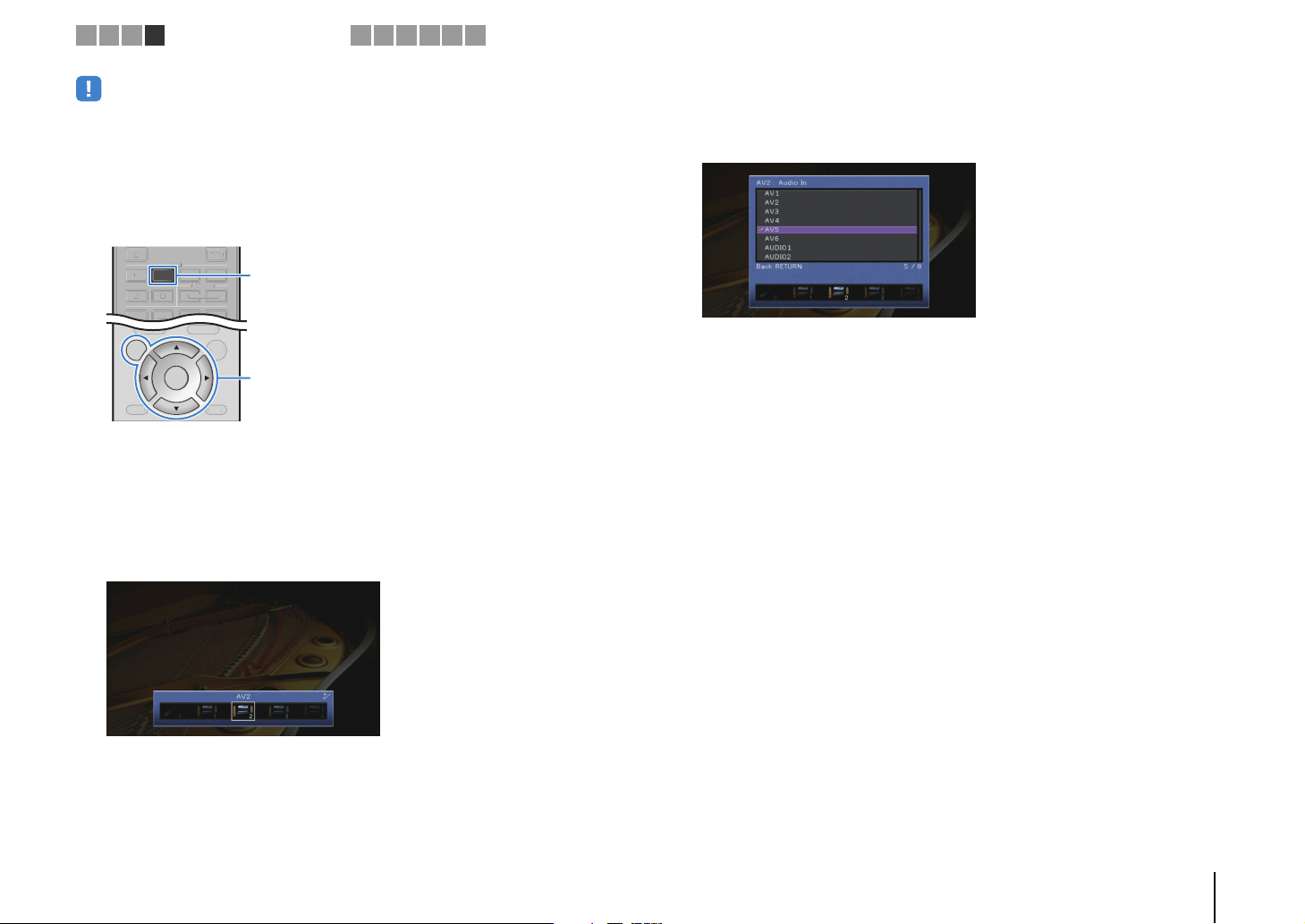
DISPLAYRETURN
ENTER
ON
SCREEN
OPTION
TOP MENU
POP-UP/MENU
DISPLAYRETURN
OPTION
TOP MENU
POP-UP/MEN
U
NET
TUNER
USB
AV
AUDIO
5
65
V-AUX
121234
TUNE
R
AV
5
6
5
V-AU
X
3
4
1 2 3 4
• The following operation is available only when your TV is connected to the unit via HDMI.
After connecting external devices (such as a TV and playback
1
Playback device connections
5 6 7 8 9 10
devices) and power cable of the unit, turn on the unit.
Press AV 2 to select “AV 2” (video input jack to be used) as the input
2
source.
AV 2
ON SCREEN
Cursor keys
ENTER
Press ON SCREEN.
3
Use the cursor keys to select “Input” and press ENTER.
4
Use the cursor keys (e/r) to select “AV2” (video input jack to be
5
used) and press the cursor key (q).
Use the cursor keys to select “Audio In” and press ENTER.
6
Use the cursor keys to select “AV5” (audio input jack to be used).
7
Press ON SCREEN.
8
This completes the necessary settings.
If you select “AV 2” as the input source by pressing AV 2, the video/audio played back
on the video device will be output from the unit.
PREPARATIONS ➤ Connecting playback devices En 30
Page 31

COMPONENT
AV 1AV 2AV 3 AV 4 AV 5
AUDIO 1 AUDIO 2
AV
OUT
AV 6
VIDEO
VIDEO
OPTICAL OPTICAL
(TV)
COAXIAL COAXIAL
COMPONENT
VIDEO
P
B
Y
MONITOR
P
R
P
B
Y
P
R
HDMI 1
(
BD/DVD
)
NETWORKDC OUT
5V
0.5A
(
NET
)
HD
ANTENNA
(
RADIO
)
HDMI
12
OUT
ARC
FM
AM
1 2 3 4
Playback device connections
5 6 7 8 9 10
Connecting audio devices (such as CD players)
Connect audio devices such as CD players and MD players to the unit. Depending on
the audio output jacks available on your audio device, choose one of the following
connections.
Audio output jacks on audio device Audio output jacks on the unit
Digital optical
Digital coaxial AV 2–3 (COAXIAL)
Analog stereo
The unit (rear)
OO
OPTICAL
COAXIAL
L
R
AV 1–6 jacks
AUDIO 1–2 jacks
CC
L
R
(either digital optical,
digital coaxial, or analog stereo)
If you select the input source by pressing AV 1–6 or AUDIO 1–2, the audio played back
on the audio device will be output from the unit.
AV 1 (OP T ICA L)
AV 4 (OP T ICA L)
AV 5–6 (AUDIO)
OPTICAL
COAXIAL
L
L
R
R
Audio output
AUDIO 1–2
Audio device
Connecting to the jacks on the front panel
Use the VIDEO AUX jack to temporarily connect devices such as game consoles and
camcorders to the unit.
Use the USB jack to connect an iPod or a USB storage device. For details, see
“Connecting an iPod” (p.58) or “Connecting a USB storage device” (p.62).
Before making a connection, stop playback on the device and turn down the volume on
the unit.
BD
TV
DVD
PHONES
SILENT
CINEMA
YPAO MIC
CONTROL
TONE
PROGRAM
The unit (front)
Game console
Camcorder
If you select “V-AUX” as the input source by pressing V-AUX, the video/audio played
back on the device will be output from the unit.
RADIO
NET
AUX US B
VIDEO
STRAIGHT
VIDEO
HDMI IN
HDMI
iPod/iPhone/iPad
5V 2.1A
• To watch videos input to the VIDEO AUX (HDMI IN) jack, you need to connect your TV to the HDMI OUT
jack of the unit (p.23 to 26).
• You need to prepare an HDMI cable that match the output jacks on your device.
• When “USB” is selected as the input source, video signals input to the VIDEO jack are output from the
HDMI OUT and MONITOR OUT (VIDEO) jacks.
PREPARATIONS ➤ Connecting playback devices En 31
Page 32

A
1 2 3 4 5
FM/AM antenna connections6Network connections
7 8 9 10
5 Connecting the FM/AM antennas
Connect the supplied FM/AM antennas to the unit.
Fix the end of the FM antenna to a wall, and place the AM antenna on a flat surface.
ANTENNA
AM
(
RADIO
HDMI 1
(
BD/DVD
)
FM
FM antenna
)
COMPONENT
VIDEO
R
P
P
B
VIDEO
Y
MONITOR OUT
REMOTE
IN
OUT
12V
0.1A
HDMI 4 HDMI 5HDMI 3HDMI 2
FRONT CENTER SURROUND
SPE
AM antenna
The unit (rear)
5V
COMPONENT
P
R
P
B
Y
NETWORKDC OUT
(
)
NET
0.5A
VIDEO
12
VIDEO
OUT
HDMI
ARC
Assembling and connecting the AM antenna
6 Connecting to a network
Connect the unit to your router with a commercially-available STP network cable (CAT-5
or higher straight cable).
You can enjoy Internet radio or music files stored on media servers, such as PCs and
Network Attached Storage (NAS), on the unit.
Internet
Modem
Router
Mobile device
(such as iPod touch
and iPhone)
WAN
LAN
Network Attached Storage
Network cable
NETWORKDC OUT
(
)
NET
5V
0.5A
COMPONENT
VIDEO
P
R
P
B
VIDEO
Y
OPTICAL OPTICAL
COAXIAL COAXIAL
AV 1AV 2AV 3 AV 4 AV 5
(NAS)
PC
OUT
HDMI
12
ARC
(TV)
AV 6
HDMI 1
HDMI 2
(
)
BD/DVD
ANTENNA
(
)
RADIO
COMPONENT
VIDEO
FM
AM
P
R
P
B
VIDEO
Y
MONITOR OUT
AV
OUT
AUDIO 1 AUDIO 2
The unit (rear)
Hold down Insert Release
• Unwind only the length of cable needed from the AM antenna unit.
• The wires of the AM antenna have no polarity.
• If you are using a router that supports DHCP, you do not need to configure any network settings for the unit,
as the network parameters (such as the IP address) will be assigned automatically to it. You only need to
configure the network settings if your router does not support DHCP or if you want to configure the network
parameters manually (p.98).
• You can check whether the network parameters (such as IP address) are properly assigned to the unit in
“Network” (p.104) in the “Information” menu.
• Some security software installed on your PC or the firewall settings of network devices (such as a router)
may block the access of the unit to the network devices or the Internet. In these cases, configure the
security software or firewall settings appropriately.
• Each server must be connected to the same subnet as the unit.
• To use the service via the Internet, broadband connection is strongly recommended.
PREPARATIONS ➤ Connecting the FM/AM antennas En 32
Page 33

E
1 2 3 4 5 6 7
Other connections
8 9 10
7 Connecting other devices
Connecting an external power amplifier
(HTR-7065 only)
When connecting an external power amplifier (pre-main amplifier) to enhance speaker
output, connect the input jacks of the power amplifier to the PRE OUT jacks of the unit.
The same channel signals are output from the PRE OUT jacks as from their
corresponding SPEAKERS terminals.
Caution
• To prevent the generation of loud noises or abnormal sounds, make sure the followings before making
connections.
– Remove the power cable of the unit and turn off the external power amplifier before connecting them.
– When using the PRE OUT jacks, do not connect speakers to the corresponding SPEAKERS
terminals.
– When using an external amplifier that does not have the volume control bypass, do not connect other
devices (except the unit) to the amplifier.
The unit (rear)
HDMI 1
(
)
OUT
HDMI
BD/DVD
2
C
ANTENNA
(
)
RADIO
COMPONENT
VIDEO
FM
AM
P
R
P
B
Y
MONITOR OUT
AV
OUT
AV 5
AV 6
AUDIO 1 AUDIO 2
1 FRONT jacks
Output front channel sounds.
2 SURROUND jacks
Output surround channel sounds.
3 SUR. BACK jacks
Output surround back channel sounds. When using only one external amplifier for the surround
back channel, connect it to the SINGLE jack (L side).
HDMI 4 HDMI 5HDMI 3HDMI 2
SPEAKERS
FRONT CENTER SURROUND
REMOTE
IN
OUT
VIDEO
12V
0.1A
TRIGGER OUT
AUDIO
ZONE 2
OUT
OUT
1 2 3 4
SURROUND BACK/BI AMP
ZONE 2/PRESENCE
SINGLE
SUBWOOFER
12
EXTRA SP
SINGLE CENTER
SURROUND SUR. BACK
FRONT
PRE OUT
5
4 SUBWOOFER1–2 jacks
For connecting a subwoofer with built-in amplifier. When 2 subwoofers are connected, the same
sound is output from them.
5 CENTER jack
Outputs center channel sounds.
Connecting recording devices
You can connect video/audio recording devices to the AV OUT and AUDIO OUT jacks.
These jacks output analog video/audio signals selected as the input.
• To copy video/audio from a video device, connect the video device to the AV 5–6 jacks of the unit.
• To copy audio from an audio device, connect the audio device to the AV 5–6 jacks or AUDIO 1–2 jacks of
the unit.
• Be sure to use the AV OUT and AUDIO OUT jacks only for connecting recording devices.
Video/audio input
VIDEO
V
L
L
R
R
AUDIO
L
L
R
R
AUDIO
Audio inputAUDIO OUT jacks
Video recording
device
Audio recording
device
The unit (rear)
OUT
HDMI
12
ARC
ANTENNA
(
AM
VIDEO
OPTICAL
COAXIAL
(TV)
AV 3 AV 4 AV 5
AV 6
AV OUT jacks
HDMI 1
(
)
BD/DVD
)
RADIO
COMPONENT
VIDEO
FM
P
R
P
B
Y
MONITOR OUT
AV
OUT
AUDIO 1 AUDIO 2
V
HDMI 4 HDMI 5HDMI 3HDMI 2
L
FRONT CENT
REMOTE
IN
R
OUT
VIDEO
AV
OUT
12V
0.1A
TRIGGER OUT
AUDIO
ZONE 2
OUT
OUT
L
R
AUDIO
OUT
PREPARATIONS ➤ Connecting other devices En 33
Page 34

O
E
1 2 3 4 5 6 7
Other connections
8 9 10
Connecting a device that supports SCENE link playback (remote connection)
If you have a Yamaha product that supports SCENE control signal transmission, you
can operate it remotely by connecting it to the REMOTE OUT jack, using a monaural
mini-jack cable, and linking with the SCENE function (p.46).
The unit
(rear)
12
VIDEO
OPTICAL
COAXIAL
(TV)
AV 3 AV 4 AV 5
• If you connect a Yamaha product that supports the SCENE link playback function, to the REMOTE OUT
jack, you can remotely start playback on it by linking with a scene selection (p.46). To enable the SCENE
link playback function, specify the device type in “Device Control” (p.84) in the “Scene” menu.
• You can also connect an infrared signal receiver/emitter to operate devices in the main zone from Zone2
(p.74).
OUT
HDMI
ARC
ANTENNA
(
)
RADIO
AM
AV
OUT
AV 6
REMOTE OUT jack
REMOTE
IN
HDMI 1
(
)
BD/DVD
FM
AUDIO 1 AUDIO 2
COMPONENT
VIDEO
P
R
P
B
Y
MONITOR OUT
HDMI 4HDMI 3HDMI 2
OUT
REMOTE
IN
OUT
VIDEO
12V
0.1A
TRIGGER OUT
Remote input
REMOTE
IN
FR
Yamaha product
(such as a DVD player)
Connecting a device compatible with the trigger function
The trigger function can control an external device in conjunction with operating the
unit (such as powering on/off and input selection). If you have a Yamaha subwoofer that
supports a system connection or a device with a trigger input jack, you can use the
trigger function by connecting the external device to the TRIGGER OUT jack.
The unit (rear)
HDMI 1
(
)
OUT
HDMI
BD/DVD
2
ARC
ANTENNA
(
)
RADIO
COMPONENT
VIDEO
FM
AM
P
R
P
B
Y
MONITOR OUT
AV
OUT
AV 5
AV 6
AUDIO 1 AUDIO 2
TRIGGER OUT jack
• You can configure the trigger function settings in “Trigger Output” (p.101) in the “Setup” menu.
VIDEO
REMOTE
IN
OUT
12V
0.1A
TRIGGER OUT
12V
0.1A
TRIGGER OUT
HDMI 4 HDMI 5HDMI 3HDMI 2
FRONT C
AUDIO
OUT
System connection
input
ZONE 2
OUT
Yamaha subwoofer that
supports a system connection
PREPARATIONS ➤ Connecting other devices En 34
Page 35

1 2 3 4 5 6 7 8
Power cable connection
9 10
8 Connecting the power cable
After all the connections are complete, plug in the power cable.
The unit (rear)
MI 5
CENTER SURROUND
SPEAKERS
SURROUND BACK/BI AMP
ZONE 2/PRESENCE
SINGLE
To an AC wall outlet
SUBWOOFER
12
EXTRA SP
SINGLE CENTER
SURROUND SUR. BACK
FRONT
NE 2
UT
PRE OUT
PREPARATIONS ➤ Connecting the power cable En 35
Page 36

VO
U
CO
SE
0
MEMO
5
6
8
3
E
T
RETURN
O
T
M
N
U
S
T
O
S
C
T
E
ZO
SCENE
O
SOURC
REC
R
AV
A
5
6
5
V-AU
2
3
4
2
3
4
SU
E
1 2 3 4 5 6 7 8 9
RECEIVER
EIVE
SOURCE
HDMI
1234
5
AV
121234
TUNER
TUN
MAIN
BD
DVD
PROGRAM VOLUME
ROGRAMVOLUM
ON
SCREEN
MODE
MODE
MOVIE
VI
INFO SLEEP
INF
1234
1 2
5
90
9
INPUT
INP
MUTE
MUTE
AUDIO
65
USB
SB
NET
PARTY HDMI OUT
PARTYHDMI OU
ZONE 2
NE
SCENE
TV
NET
UTE
MUTE
OP MENU
TOP MENU
POP-UP/MENU
POP-UP/ME
ENTER
TUNING PRESET
TUNINGPRESE
SUR. DECODE
R. DECOD
MUSIC
ENHANCER
NHANCER
LEE
687
MEMORY
RY
10
TV
TV VOL TV CH
TV CH
V-AUX
DI
2
RADIO
PTION
OPTION
DISPLAYRETURN
DISPLA
BAND
STRAIGHT
TRAIGH
PURE DIRECT
PURE DIRECT
4
ENT
CODE SET
DE
RECEIVER z
ON SCREEN
Cursor keys
ENTER
Language setting
10
9 Selecting an on-screen menu language
Select the desired on-screen menu language from English
(default), Japanese, French, German, Spanish, Russian and
Chinese.
Press RECEIVER z to turn on the unit.
1
Turn on the TV and switch the TV input to display
2
video from the unit (HDMI OUT jack).
Press ON SCREEN.
3
Use the cursor keys to select “Setup” and press
4
ENTER.
Use the cursor keys (e/r) to select “Language” and
5
the cursor keys (q/w) to select the desired
language.
To confirm the setting, press ENTER.
6
To exit from the menu, press ON SCREEN.
7
• The information on the front display is provided in English only.
PREPARATIONS ➤ Selecting an on-screen menu language En 36
Page 37

1 2 3 4 5 6 7 8 9 10
VO
U
CO
SE
0
MEMO
5
6
8
3
E
T
RETURN
O
S
E
N
O
T
M
N
U
S
T
O
S
C
T
E
ZO
SCENE
O
SOURC
REC
R
AV
A
5
6
5
V-AU
2
3
4
2
3
4
SU
E
RECEIVER
EIVE
SOURCE
HDMI
1234
5
AV
121234
TUNER
TUN
MAIN
BD
DVD
PROGRAM VOLUME
ROGRAMVOLUM
N
ON
CRE
SCREEN
MODE
MODE
MOVIE
VI
INFO SLEEP
INF
1234
1 2
5
90
9
INPUT
INP
MUTE
MUTE
AUDIO
65
USB
SB
NET
PARTY HDMI OUT
PARTYHDMI OU
ZONE 2
NE
SCENE
TV
NET
UTE
MUTE
OP MENU
TOP MENU
POP-UP/MENU
POP-UP/ME
ENTER
TUNING PRESET
TUNINGPRESE
SUR. DECODE
R. DECOD
MUSIC
ENHANCER
NHANCER
LEE
687
MEMORY
RY
10
TV
TV VOL TV CH
TV CH
V-AUX
DI
2
RADIO
PTION
OPTION
DISPLAYRETURN
DISPLA
BAND
STRAIGHT
TRAIGH
PURE DIRECT
PURE DIRECT
4
ENT
CODE SET
DE
RECEIVER z
Automatic speaker setup
10 Optimizing the speaker settings automatically (YPAO)
The Yamaha Parametric room Acoustic Optimizer (YPAO) function
detects speaker connections, measures the distances from them to
your listening position(s), and then automatically optimizes the
speaker settings, such as volume balance and acoustic
parameters, to suit your room.
• Please note the following when using YPAO.
– Use YPAO after connecting a TV and speakers to the unit.
– During the measuring process, test tones are output at high volume. Ensure that
the test tones do not frighten small children. Also, refrain from using this function
at night when it may be a nuisance to others.
– During the measuring process, you cannot adjust the volume.
– During the measuring process, keep the room as quiet as possible.
– Do not connect headphones.
Press RECEIVER z to turn on the unit.
1
Turn on the TV and switch the TV input to display
2
video from the unit (HDMI OUT jack).
Turn on the subwoofer and set the volume to half. If
3
the crossover frequency is adjustable, set it to
maximum.
VOLUME HIGH CUT
CROSSOVER/
9
MIN MAXMIN MAX
Place the YPAO microphone at your listening
4
position (same height as your ears) and connect it
to the YPAO MIC jack on the front panel.
YPAO MIC
9
45
jack
YPAO MIC
The unit (front)
12
3
YPAO
microphone
Ear height
Place the YPAO microphone at
your listening position (same height
as your ears). We recommend the
use of a tripod as a microphone
stand. You can use the tripod
screws to stabilize the microphone.
• If you are using bi-amp connection or Zone2 speakers, set “Power Amp
Assign” (p.91) in the “Setup” menu to the appropriate setting before starting
YPAO.
PREPARATIONS ➤ Optimizing the speaker settings automatically (YPAO) En 37
Page 38

1 2 3 4 5 6 7 8 9 10
VO
U
CO
SE
0
MEMO
5
6
8
3
E
T
RETURN
O
S
E
N
O
T
M
N
U
S
T
O
S
C
T
E
ZO
SCENE
O
SOURC
REC
R
AV
A
5
6
5
V-AU
2
3
4
2
3
4
SU
E
Automatic speaker setup
RECEIVER
EIVE
SOURCE
HDMI
1234
5
AV
121234
TUNER
TUN
MAIN
BD
DVD
PROGRAM VOLUME
ROGRAMVOLUM
N
ON
CRE
SCREEN
MODE
MODE
MOVIE
VI
INFO SLEEP
INF
1234
1 2
5
90
9
INPUT
INP
MUTE
MUTE
AUDIO
65
USB
SB
NET
PARTY HDMI OUT
PARTYHDMI OU
ZONE 2
NE
SCENE
TV
NET
UTE
MUTE
OP MENU
TOP MENU
POP-UP/MENU
POP-UP/ME
ENTER
TUNING PRESET
TUNINGPRESE
SUR. DECODE
R. DECOD
MUSIC
ENHANCER
NHANCER
LEE
687
MEMORY
RY
10
TV
TV VOL TV CH
TV CH
V-AUX
DI
2
RADIO
PTION
OPTION
DISPLAYRETURN
DISPLA
BAND
STRAIGHT
TRAIGH
PURE DIRECT
PURE DIRECT
4
ENT
CODE SET
DE
Cursor keys
ENTER
The following screen appears on the TV.
(HTR-6065)
(HTR-7065)
(HTR-6065)
This completes the preparations.
See “Measuring at one listening position (single measure)”
(p.39) to start the measurement.
(HTR-7065)
Proceed to Step 5.
(HTR-7065 only) If desired, change the measuring
5
method (multi/single).
a Use the cursor keys to select “Multi Position” and press ENTER.
b Use the cursor keys to select a setting and then press ENTER.
Settings
Select this option if you will have several listening
positions or if you want others to enjoy surround sound.
Yes
No (default)
• If you perform the multi measure, the speaker settings will be optimized for you to
enjoy surround sound in a wider space.
• If you perform the multi measure, first place the YPAO microphone at the listening
position you will be seated most frequently.
You can take measurements at up to 8 different
positions in the room. The speaker settings will be
optimized to suit the area defined by those positions
(multi measure).
Select this option if your listening position will always be
fixed. Take the measurements at only one position. The
speaker settings will be optimized to suit that position
(single measure).
• To cancel the operation, disconnect the YPAO microphone before starting
the measurement.
PREPARATIONS ➤ Optimizing the speaker settings automatically (YPAO) En 38
Page 39

VO
U
CO
SE
0
MEMO
5
6
8
3
E
T
O
S
E
N
O
T
M
N
U
S
T
O
S
C
T
E
ZO
SCENE
O
SOURC
REC
R
AV
A
5
6
5
V-AU
2
3
4
2
3
4
SU
E
1 2 3 4 5 6 7 8 9 10
Automatic speaker setup
RECEIVER
EIVE
SOURCE
HDMI
1234
5
AV
121234
TUNER
TUN
MAIN
BD
DVD
PROGRAM VOLUME
ROGRAMVOLUM
N
ON
CRE
SCREEN
MODE
MODE
MOVIE
VI
INFO SLEEP
INF
1234
1 2
5
90
9
INPUT
INP
MUTE
MUTE
AUDIO
65
USB
SB
NET
PARTY HDMI OUT
PARTYHDMI OU
ZONE 2
NE
SCENE
TV
NET
UTE
MUTE
OP MENU
TOP MENU
POP-UP/MENU
POP-UP/ME
ENTER
TUNING PRESET
TUNINGPRESE
SUR. DECODE
R. DECOD
MUSIC
ENHANCER
NHANCER
LEE
687
MEMORY
RY
10
TV
TV VOL TV CH
TV CH
V-AUX
DI
2
RADIO
PTION
OPTION
DISPLAYRETURN
DISPLA
BAND
STRAIGHT
TRAIGH
PURE DIRECT
PURE DIRECT
4
ENT
CODE SET
DE
Cursor keys
ENTER
RETURN
Multi measure
Single measure
a
(1 listening position + front/back/left/right)
Multi measure
b
a
cde
(5 listening positions)
de
bac
(2 listening positions + front/back)
Multi measure
c
a b
d
This completes the preparations. See the following page to start the
measurement.
When “Multi Position” is set to “Yes”:
“Measuring at multiple listening positions (multi measure)
(HTR-7065 only)” (p.40)
When “Multi Position” is set to “No”:
“Measuring at one listening position (single measure)” (p.39)
Measuring at one listening position
(single measure)
Follow the procedure below for measurement.
• Do not stand between the speakers and the YPAO microphone during the
measurement process (about 3 minutes).
• Move to the corner of the room or leave the room.
To start the measurement, use the cursor keys to
1
select “Measure” and press ENTER.
The measurement will start in 10 seconds. Press ENTER
again to start the measurement immediately.
• To cancel the measurement temporarily, press RETURN.
The following screen appears on the TV when the
measurement finishes.
• If any error message (such as E-1) or warning message (such as W-1)
appears, see “Error messages” (p.43) or “Warning messages” (p.44).
• To check the measurement results, select “Result”. For details, see
“Checking the measurement results” (p.41).
PREPARATIONS ➤ Optimizing the speaker settings automatically (YPAO) En 39
Page 40

VO
U
CO
SE
0
MEMO
5
6
8
3
E
T
O
S
E
N
O
T
M
N
U
S
T
O
S
C
T
E
ZO
SCENE
O
SOURC
REC
R
AV
A
5
6
5
V-AU
2
3
4
2
3
4
SU
E
1 2 3 4 5 6 7 8 9 10
Automatic speaker setup
RECEIVER
EIVE
SOURCE
HDMI
1234
5
AV
121234
TUNER
TUN
MAIN
BD
DVD
PROGRAM VOLUME
ROGRAMVOLUM
N
ON
CRE
SCREEN
MODE
MODE
MOVIE
VI
INFO SLEEP
INF
1234
1 2
5
90
9
INPUT
INP
MUTE
MUTE
AUDIO
65
USB
SB
NET
PARTY HDMI OUT
PARTYHDMI OU
ZONE 2
NE
SCENE
TV
NET
UTE
MUTE
OP MENU
TOP MENU
POP-UP/MENU
POP-UP/ME
ENTER
TUNING PRESET
TUNINGPRESE
SUR. DECODE
R. DECOD
MUSIC
ENHANCER
NHANCER
LEE
687
MEMORY
RY
10
TV
TV VOL TV CH
TV CH
V-AUX
DI
2
RADIO
PTION
OPTION
DISPLAYRETURN
DISPLA
BAND
STRAIGHT
TRAIGH
PURE DIRECT
PURE DIRECT
4
ENT
CODE SET
DE
Cursor keys
ENTER
RETURN
Use the cursor keys to select “Save/Cancel” and
2
press ENTER.
To save the measurement results, use the cursor
3
keys (e/r) to select “SAVE” and press ENTER.
The adjusted speaker settings are applied.
• To finish the measurement without saving the result, select “CANCEL”.
Disconnect the YPAO microphone from the unit.
4
This completes optimization of the speaker settings.
Caution
• The YPAO microphone is sensitive to heat, so should not be placed anywhere
where it could be exposed to direct sunlight or high temperatures (such as on
top of AV equipment).
Measuring at multiple listening positions
(multi measure) (HTR-7065 only)
When “Multi Position” is set to “Yes”, follow the procedure below for
measurement.
• Do not stand between the speakers and the YPAO microphone during the
measurement process. It takes about 10 minutes to measure 8 listening positions.
• Move to the corner of the room or leave the room.
• If any error message (such as E-1) or warning message (such as W-1) appears,
see “Error messages” (p.43) or “Warning messages” (p.44).
To start the measurement, use the cursor keys to
1
select “Measure” and press ENTER.
The measurement will start in 10 seconds. Press ENTER
again to start the measurement immediately.
• To cancel the measurement temporarily, press RETURN.
The following screen appears on the TV when the
measurement at the first position finishes.
Move the YPAO microphone to the next listening
2
position and press ENTER.
Repeat step 2 until measurements at all listening positions
(up to 8) have been taken.
PREPARATIONS ➤ Optimizing the speaker settings automatically (YPAO) En 40
Page 41

VO
U
CO
SE
0
MEMO
5
6
8
3
E
T
RETURN
O
S
E
N
O
T
M
N
U
S
T
O
S
C
T
E
ZO
SCENE
O
SOURC
REC
R
AV
A
5
6
5
V-AU
2
3
4
2
3
4
SU
E
1 2 3 4 5 6 7 8 9 10
RECEIVER
EIVE
SOURCE
HDMI
1234
AV
65
USB
SB
SCENE
TV
UTE
MUTE
ENTER
SUR. DECODE
R. DECOD
ENHANCER
NHANCER
LEE
687
MEMORY
TV
TV VOL TV CH
V-AUX
AUDIO
DI
2
NET
PARTY HDMI OUT
PARTYHDMI OU
NET
RADIO
POP-UP/MENU
POP-UP/ME
PTION
OPTION
DISPLAYRETURN
DISPLA
BAND
STRAIGHT
TRAIGH
PURE DIRECT
PURE DIRECT
4
RY
ENT
10
TV CH
CODE SET
DE
Cursor keys
ENTER
5
121234
TUNER
TUN
MAIN
ZONE 2
NE
BD
DVD
PROGRAM VOLUME
ROGRAMVOLUM
OP MENU
TOP MENU
N
ON
CRE
SCREEN
MODE
MODE
TUNING PRESET
TUNINGPRESE
MOVIE
MUSIC
VI
INFO SLEEP
INF
1234
1 2
5
90
9
INPUT
INP
MUTE
MUTE
Automatic speaker setup
When the measurements at the positions you want
3
to measure are completed, use the cursor keys to
select “CANCEL” and press ENTER.
When you have taken measurements at 8 listening
positions, the following screen appears automatically.
• To check the measurement results, select “Result”. For details, see
“Checking the measurement results” (p.41).
Use the cursor keys to select “Save/Cancel” and
4
press ENTER.
To save the measurement result, use the cursor
5
keys to select “SAVE” and press ENTER.
Disconnect the YPAO microphone from the unit.
6
This completes optimization of the speaker settings.
Caution
• The YPAO microphone is sensitive to heat, so should not be placed anywhere
where it could be exposed to direct sunlight or high temperatures (such as on
top of AV equipment).
Checking the measurement results
You can check the YPAO measurement results.
After the measurement, use the cursor keys to
1
select “Result” and press ENTER.
• You can also select “Result” from “Auto Setup” (p.89) in the “Setup” menu,
which displays the previous measurement results.
The following screen appears.
1
2
3
1 Measurement result items
2 Measurement result details
3 The number of measured positions (when multi
The adjusted speaker settings are applied.
• To finish the measurement without saving the result, select “CANCEL”.
measure is performed) * HTR-7065 only
PREPARATIONS ➤ Optimizing the speaker settings automatically (YPAO) En 41
Page 42

VO
U
CO
SE
0
MEMO
5
6
8
3
E
T
O
T
M
N
U
S
T
O
S
C
T
E
ZO
SCENE
O
SOURC
REC
R
AV
A
5
6
5
V-AU
2
3
4
2
3
4
SU
E
1 2 3 4 5 6 7 8 9 10
Automatic speaker setup
RECEIVER
EIVE
SOURCE
HDMI
1234
5
AV
121234
TUNER
TUN
MAIN
BD
DVD
PROGRAM VOLUME
ROGRAMVOLUM
ON
SCREEN
MODE
MODE
MOVIE
VI
INFO SLEEP
INF
1234
1 2
5
90
9
INPUT
INP
MUTE
MUTE
AUDIO
65
USB
SB
NET
PARTY HDMI OUT
PARTYHDMI OU
ZONE 2
NE
SCENE
TV
NET
UTE
MUTE
OP MENU
TOP MENU
POP-UP/MENU
POP-UP/ME
ENTER
TUNING PRESET
TUNINGPRESE
SUR. DECODE
R. DECOD
MUSIC
ENHANCER
NHANCER
LEE
687
MEMORY
RY
10
TV
TV VOL TV CH
TV CH
V-AUX
DI
2
RADIO
PTION
OPTION
DISPLAYRETURN
DISPLA
BAND
STRAIGHT
TRAIGH
PURE DIRECT
PURE DIRECT
4
ENT
CODE SET
DE
ON SCREEN
Cursor keys
ENTER
RETURN
Use the cursor keys to select an item
2
Polarity of each speaker
Wiring
Size
Normal: The speaker cable is connected with the
correct polarity (+/-).
Reverse: The speaker cable may be connected with the
reverse polarity (+/-).
Size of each speaker (cross-over frequency of the
subwoofer)
Large: The speaker can reproduce low-frequency
signals effectively.
Small: The speaker cannot reproduce low-frequency
signals effectively.
Distance Distance from the listening position to each speaker
Level Output level adjustment for each speaker
• A speaker with a problem is indicated with a message enclosed in a red box.
To finish checking the results and return to the
3
previous screen, press RETURN.
Reloading the previous YPAO adjustments
When the speaker settings you have configured manually are not
suitable, follow the procedure below to discard the manual settings
and reload the previous YPAO adjustments.
In the “Setup” menu, select “Speaker”, “Auto
1
Setup”, and then “Result” (p.88).
Use the cursor keys to select “Setup Reload” and
2
press ENTER.
To exit from the menu, press ON SCREEN.
3
PREPARATIONS ➤ Optimizing the speaker settings automatically (YPAO) En 42
Page 43

1 2 3 4 5 6 7 8 9 10
Automatic speaker setup
Error messages
If any error message is displayed during the measurement, resolve the problem and perform YPAO again.
Error message Cause Remedy
E-1: No Front SP Front speakers are not detected.
Follow the on-screen instructions to exit YPAO, turn off the unit, and then check the speaker connections.E-2: No Sur. SP One of the surround speakers cannot be detected.
E-3: No F.PRNS SP One of the presence speakers cannot be detected.
E-4: SBR → SBL A surround back speaker is connected to the R side only.
E-5: Noisy The noise is too loud.
E-6: Check Sur.
E-7: No MIC The YPAO microphone has been removed.
E-8: No Signal The YPAO microphone cannot detect test tones.
E-9: User Cancel The measurement has been canceled. Follow the on-screen instructions to start the measurement again. To cancel the measurement, select “EXIT”.
E-10: Internal Error An internal error has occurred.
Surround back speakers are connected, but no surround
speakers are connected
When using only one surround back speaker, you need to connect it to the SINGLE jack (L side). Follow the
on-screen instructions to exit YPAO, turn off the unit, and then reconnect the speaker.
Keep the room quiet and follow the on-screen instructions to start the measurement again. If you select
“PROCEED”, YPAO takes the measurement again and ignores any noise detected.
Surround speakers need to be connected in order to use surround back speakers. Follow the on-screen
instructions to exit YPAO, turn off the unit, and then reconnect the speakers.
Connect the YPAO microphone to the YPAO MIC jack firmly and follow the on-screen instructions to start the
measurement again.
Connect the YPAO microphone to the YPAO MIC jack firmly and follow the on-screen instructions to start the
measurement again. If this error occurs repeatedly, contact the nearest authorized Yamaha dealer or service
center.
Follow the on-screen instructions to exit YPAO, turn off and on the unit. If this error occurs repeatedly, contact
the nearest authorized Yamaha dealer or service center.
PREPARATIONS ➤ Optimizing the speaker settings automatically (YPAO) En 43
Page 44

1 2 3 4 5 6 7 8 9 10
Automatic speaker setup
Warning messages
If a warning message is displayed after the measurement, you can still save the measurement results by following on-screen instructions.
However, we recommend you perform YPAO again in order to use the unit with the optimal speaker settings.
Warning message Cause Remedy
Select “Wiring” in “Result” (p.41) and check the cable connections (+/-) of the speaker identified by
“Reverse”. If the speaker is connected incorrectly, turn off the unit and then reconnect the speaker cable.
Depending on the type of speakers or room environment, this message may appear even if the speakers are
connected correctly.
Select “Distance” in “Result” (p.41) and move the speaker identified by “>24.0m (>80.0ft)” within 24 m (80 ft)
of the listening position.
Check the usage environment and cable connections (+/-) of each speaker, and the volume of the
subwoofer. We recommend using the same speakers or speakers with specifications that are as similar as
possible.
W-1: Out of Phase
W-2: Over Distance
W-3: Level Error
A speaker cable may be connected with the reverse polarity
(+/-).
A speaker is placed more than 24 m (80 ft) from the listening
position.
There are significant volume differences between the
speakers.
PREPARATIONS ➤ Optimizing the speaker settings automatically (YPAO) En 44
Page 45

RECEIVER
VO
U
CO
SE
0
MEMO
5
6
8
3
E
T
RETURN
O
T
M
N
U
S
T
O
S
C
ZO
SCENE
O
SOURC
REC
R
SU
E
EIVE
SOURCE
HDMI
1234
5
AV
121234
TUNER
MAIN
BD
DVD
PROGRAM VOLUME
ROGRA
ON
SCREEN
MODE
MODE
MOVIE
VI
INFO SLEEP
INF
1234
1 2
5
90
9
INPUT
INP
MUTE
MUTE
AUDIO
65
USB
NET
PARTY HDMI OUT
PARTY
ZONE 2
NE
SCENE
TV
NET
MUTE
OP MENU
TOP MENU
POP-UP/MENU
POP-UP/ME
ENTER
TUNING PRESET
TUNINGPRESE
SUR. DECODE
R. DECOD
MUSIC
ENHANCER
NHANCER
LEE
687
MEMORY
RY
10
TV
TV VOL TV CH
TV CH
V-AUX
RADIO
PTION
OPTION
DISPLAYRETURN
DISPLA
BAND
STRAIGHT
TRAIGH
PURE DIRECT
PURE DIRECT
4
ENT
CODE SET
DE
Input selection keys
HDMI OUT
MUTE
VOLUME
ON SCREEN
Cursor keys
ENTER
PLAYBACK
Basic playback procedure
Turn on the external devices (such as a TV or
1
BD/DVD player) connected to the unit.
Use the input selection keys to select an input
2
source.
Start playback on the external device or select a
3
radio station.
Refer to the instruction manual for the external device.
For details on the following operations, see the
corresponding pages.
• Listening to FM/AM radio (p.53)
• Playing back iPod music (p.58)
• Playing back music stored on a USB storage device
(p.62)
• Playing back music stored on media servers (PCs/NAS)
(p.65)
• Listening to Internet radio (p.68)
• Playing back iTunes/iPod music via a network (AirPlay)
(p.70)
Press VOLUME to adjust the volume.
4
Selecting an HDMI output jack
(HTR-7065 only)
Press HDMI OUT to select an HDMI OUT jack.
1
Each time you press the key, the HDMI OUT jack to be
used for signal output changes.
VOL.
SW
C
LR
HDMIOUT1+2
HDMI OUT 1+2
HDMI OUT 1
HDMI OUT 2
HDMI OUT Off Does not output the signals at the HDMI OUT jacks.
• You can also select an HDMI output jack by selecting a scene (p.46).
• When “HDMI OUT 1+2” is selected, the unit outputs video signals at the highest
resolution supported by both TVs (or projectors) connected to the unit. (For
example, if you have connected a 1080p TV to the HDMI OUT 1 jack and a 720p
TV to the HDMI OUT 2 jack, the unit outputs 720p video signals.)
Outputs the same signal at both the HDMI OUT 1
and HDMI OUT 2 jacks.
Output the signals at the selected HDMI OUT jack.
SL SR
SBL SBR
• To mute the audio output, press MUTE. Press MUTE again to unmute.
• To adjust the treble/bass settings, use the “Option” menu or TONE
CONTROL on the front panel (p.79).
On-screen input selection
a Press ON SCREEN.
b Use the cursor keys to select “Input” and press ENTER.
c Use the cursor keys to select the desired input source and
press ENTER.
PLAYBACK ➤ Basic playback procedure En 45
Page 46

RECEIVER
VO
U
CO
SE
0
MEMO
5
6
8
3
E
T
RETURN
O
S
E
N
O
T
M
N
U
S
T
O
S
C
T
ZO
SOURC
REC
R
SU
E
EIVE
SOURCE
HDMI
1234
5
AV
121234
TUNER
MAIN
BD
DVD
PROGRAM VOLUME
ROGRAMVOLUM
N
ON
CRE
SCREEN
MODE
MODE
MOVIE
VI
INFO SLEEP
INF
1234
1 2
5
90
9
INPUT
INP
MUTE
MUTE
AUDIO
65
USB
NET
PARTY HDMI OUT
PARTYHDMI OU
ZONE 2
NE
SCENE
TV
NET
UTE
MUTE
OP MENU
TOP MENU
POP-UP/MENU
POP-UP/ME
ENTER
TUNING PRESET
TUNINGPRESE
SUR. DECODE
R. DECOD
MUSIC
ENHANCER
NHANCER
LEE
687
MEMORY
RY
10
TV
TV VOL TV CH
TV CH
V-AUX
RADIO
PTION
OPTION
DISPLAYRETURN
DISPLA
BAND
STRAIGHT
TRAIGH
PURE DIRECT
PURE DIRECT
4
ENT
CODE SET
DE
SOURCE
Input selection keys
SCENE
Selecting the input source and favorite settings with one touch (SCENE)
The SCENE function allows you to select the assigned input source,
sound program, Compressed Music Enhancer on/off, and HDMI
output jack (HTR-7065 only) with just one touch.
Press SCENE.
1
The input source and settings registered to the
corresponding scene are selected. The unit turns on
automatically when it is in standby mode.
By default, the following settings are registered for each scene.
SCENE Input
BD/DVD HDMI 1
Sound
program
MOVIE
(Sci-Fi)
TV AV 4 STRAIGHT On HDMI OUT 1+2
NET
NET
RADIO
RADIO TUNER
MUSIC
(7ch Stereo)
MUSIC
(7ch Stereo)
Compressed
Music Enhancer
HDMI output jack
(HTR-7065 only)
Off HDMI OUT 1+2
On HDMI OUT 1+2
On HDMI OUT 1+2
Configuring scene assignments
Perform the following operations to prepare the
1
settings you want to assign to a scene.
• Select an input source (p.45)
• Select a sound program (p.47)
• Enable/disable Compressed Music Enhancer (p.52)
• (HTR-7065 only)
Selecting an HDMI output jack (p.45)
Hold down the desired SCENE key until “SET
2
Complete” appears on the front display.
VOL.
SW
C
L
SETComplete
If you want to control the corresponding playback
3
device after selecting the scene, hold down the
corresponding SCENE key and input selection key
together for more than 3 seconds.
Once the setting is completed successfully, SOURCE blinks twice.
SL SR
SBL SBR
R
• If you have not registered the remote control code of the playback device yet, see
“Registering the remote control codes for playback devices” (p.109) to register it.
• You can also configure scene assignments in the “Scene” menu (p.83).
• The SCENE link playback function allows you to start playback of an external
device connected to the unit via HDMI or of a Yamaha product connected to the
REMOTE OUT jack. To enable SCENE link playback, specify the device type in
“Device Control” (p.84) in the “Scene” menu.
PLAYBACK ➤ Selecting the input source and favorite settings with one touch (SCENE) En 46
Page 47

RECEIVER
VO
U
CO
SE
0
MEMO
5
6
8
3
T
RETURN
O
T
M
N
U
O
S
T
E
ZO
SCENE
O
SOURC
REC
R
AV
A
5
6
5
V-AU
2
3
4
2
3
4
EIVE
SOURCE
HDMI
1234
5
AV
121234
TUNER
TUN
MAIN
BD
DVD
PROGRAM VOLUME
ON
SCREEN
MODE
MODE
MOVIE
INFO SLEEP
INF
1234
1 2
5
90
9
INPUT
INP
MUTE
MUTE
AUDIO
65
USB
SB
NET
PARTY HDMI OUT
PARTYHDMI OU
ZONE 2
NE
SCENE
TV
NET
VOLUM
UTE
MUTE
OP MENU
TOP MENU
POP-UP/MENU
POP-UP/ME
ENTER
TUNING PRESET
TUNINGPRESE
SUR. DECODE
MUSIC
ENHANCER
LEE
687
MEMORY
RY
10
TV
TV VOL TV CH
TV CH
V-AUX
DI
2
RADIO
PTION
OPTION
DISPLAYRETURN
DISPLA
BAND
STRAIGHT
PURE DIRECT
4
ENT
CODE SET
DE
PROGRAM
ON SCREEN
Cursor keys
ENTER
MOVIE
MUSIC
SUR.DECODE
STRAIGHT
ENHANCER
PURE DIRECT
Selecting the sound mode
The unit is equipped with a variety of sound programs and
surround decoders that allow you to enjoy playback sources with
your favorite sound mode (such as sound field effect or stereo
playback).
Selecting a sound program suitable for movies (p.48)
Press MOVIE repeatedly.
Selecting a sound program suitable for music or stereo
playback (p.49)
Press MUSIC repeatedly.
Selecting a surround decoder (p.51)
Press SUR.DECODE repeatedly.
Switching to the straight decode mode (p.50)
Press STRAIGHT.
Switching to the Pure Direct mode (p.51)
Press PURE DIRECT.
Enable Compressed Music Enhancer (p.52)
Press ENHANCER.
On-screen sound program/surround decoder selection
a Press ON SCREEN.
b Use the cursor keys to select “Sound Program” and press
ENTER.
c Use the cursor keys to select a sound program/surround
decoder and press ENTER.
• You can also switch the sound programs and surround decoder by pressing
PROGRAM.
• You can change the settings of the surround programs and surround decoders in
the “Sound Program” menu (p.85)
• The sound mode can be applied separately to each input source.
• When you play back audio signals with a sampling rate of higher than 96 kHz, the
straight decode mode (p.50) is automatically selected.
• You can check which speakers are currently outputting sound by looking at the
speaker indicators on the unit’s front panel (p.10) or at the “Audio Signal” screen in
the “Information” menu (p.103).
PLAYBACK ➤ Selecting the sound mode En 47
Page 48

Enjoying sound field effects (CINEMA DSP)
The unit is equipped with a variety of sound programs that utilize Yamaha’s original DSP
technology (CINEMA DSP). It allows you to easily create sound fields like actual movie
theaters or concert halls in your room.
Sound program category
“CINEMA DSP” lights up
VOL.
SW
C
R
L
Sci-Fi
Sound program
■ Sound programs suitable for movies (MOVIE)
The following sound programs are optimized for viewing video sources, such as
movies, TV programs, and games.
❑ MOVIE THEATER
This program creates a sound field that emphasizes the surround feeling
Standard
Spectacle
Sci-Fi
Adventure
without disturbing the original acoustic positioning of multichannel audio,
such as Dolby Digital and DTS. Its design is based on the concept of the
ideal movie theater, in which the audience is surrounded by beautiful
reverberations from the left, right, and rear.
This program delivers the scale and grandeur of spectacular movie
productions. It delivers an expansive sound space to match the
cinemascope wide-screen, and boasts a broad dynamic range, providing
everything from small delicate sounds to powerful loud booms.
This program clearly reproduces the finely elaborated sound design of the
latest Sci-Fi and SFX movies. You can enjoy a variety of
cinematographically created virtual spaces reproduced with clear
separation between dialogue, sound effects, and background music.
This program is ideal for reproducing the sound design of action and
adventure movies precisely. The sound field restrains reverberations, but
puts emphasis on reproducing a sensation of expansiveness on both sides,
powerful space expanded widely to the left and right. The restrained depth
creates a clear and powerful space, while also maintaining the articulation
of the sounds and the separation of the channels.
SL SR
This program features stable reverberations that match a wide range of
movie genres, from serious dramas to musicals and comedies. The
Drama
Mono Movie
reverberations are modest, but suitably stereophonic. The sound effects
and background music are reproduced with a gentle echo that does not
impinge on the articulation of the dialogue. You’ll never get tired listening for
long periods.
This program reproduces monaural video sources, such as classic movies,
in an atmosphere of a good old movie theater. The program creates a
pleasant space with depth, by adding breadth and the appropriate
reverberation to the original audio.
❑ ENTERTAINMENT
This program allows listeners to enjoy the rich vividness of sport broadcasts
Sports
Action Game
Roleplaying Game
Music Video
and light entertainment programs. In sports broadcasts, the commentators’
voices are positioned clearly at the center, while the atmosphere inside the
stadium is realistically conveyed by the peripheral delivery of the sounds of
the fans in a suitable space.
This program is suitable for action games, such as car racing and fighting
games. The reality of, and emphasis on, various effects makes the player
feel like they are right in the middle of the action, allowing for greater
concentration. Use this program in combination with Compressed Music
Enhancer for a more dynamic and strong sound field.
This program is suitable for role-playing and adventure games. This
program adds depth to the sound field for natural and realistic reproduction
of background music, special effects, and dialogue from a wide variety of
scenes. Use this program in combination with Compressed Music
Enhancer for a clearer and more spatial sound field.
This program allows you to enjoy videos of pop, rock, and jazz concerts, as
if you were there yourself. Immerse yourself in the hot concert atmosphere
thanks to the vividness of the singers and solos on stage, a presence
sound field that emphasizes the beat of rhythm instruments, and a surround
sound field that reproduces the space of a big live hall.
PLAYBACK ➤ Selecting the sound mode En 48
Page 49

■ Sound programs suitable for music/stereo playback
(MUSIC)
The following sound programs are optimized for listening to music sources.
You can also select stereo playback.
❑ CLASSICAL
This program simulates a Munich concert hall with approximately 2,500
Hall in Munich
Hall in Vienna
Chamber
❑ LIVE/CLUB
Cellar Club
The Roxy Theatre
The Bottom Line
seats that uses stylish wood for the interior finishing. Fine, beautiful
reverberations spread richly, creating a calming atmosphere. The listener’s
virtual seat is at the center left of the arena.
This program simulates a 1,700-seat, middle-sized concert hall with a
shoebox shape that is traditional in Vienna. Pillars and ornate carvings
create extremely complex reverberations from all around the audience,
producing a very full, rich sound.
This program creates a relatively wide space with a high ceiling, like an
audience hall in a palace. It offers pleasant reverberations that are suitable
for courtly music and chamber music.
This program simulates an intimate concert venue with a low ceiling and
homey atmosphere. A realistic, live sound field delivers powerful sounds
that make you feel as if you are sitting in the front row in front of a small
stage.
This program creates the sound field of a 460-seat rock music concert
venue in Los Angeles. The listener’s virtual seat is at the center left of the
hall.
This program creates the sound field at stage front in The Bottom Line, a
famous New York jazz club once. The floor can seat 300 people to the left
and right in a sound field offering real and vibrant sound.
❑ STEREO
2ch Stereo
7ch Stereo
Use this program to mix down multichannel sources to 2 channels. When
multichannel signals are input, they are down mixed to 2 channels and
output from the front speakers (this program does not utilize CINEMA DSP).
Use this program to output sound from all speakers. When you play back
multichannel sources, the unit mixes down the source to 2 channels, and
then outputs the sound from all speakers. This program creates a larger
sound field and is ideal for background music at parties.
PLAYBACK ➤ Selecting the sound mode En 49
Page 50

RECEIVER
VO
U
CO
SE
0
MEMO
5
6
8
3
E
T
RETURN
O
S
E
N
O
T
M
N
U
O
S
C
T
E
ZO
SCENE
O
SOURC
REC
R
AV
A
5
6
5
V-AU
2
3
4
2
3
4
SU
E
EIVE
SOURCE
HDMI
1234
5
AV
121234
TUNER
TUN
MAIN
BD
DVD
PROGRAM VOLUME
ROGRAMVOLUM
N
ON
CRE
SCREEN
MODE
MODE
MOVIE
VI
INFO SLEEP
INF
1234
1 2
5
90
9
INPUT
INP
MUTE
MUTE
AUDIO
65
USB
SB
NET
PARTY HDMI OUT
PARTYHDMI OU
ZONE 2
NE
SCENE
TV
NET
UTE
MUTE
OP MENU
TOP MENU
POP-UP/MENU
POP-UP/ME
ENTER
TUNING PRESET
TUNINGPRESE
SUR. DECODE
R. DECOD
MUSIC
ENHANCER
NHANCER
LEE
687
MEMORY
RY
10
TV
TV VOL TV CH
TV CH
V-AUX
DI
2
RADIO
PTION
OPTION
DISPLAYRETURN
DISPLA
BAND
STRAIGHT
PURE DIRECT
PURE DIRECT
4
ENT
CODE SET
DE
STRAIGHT
■ Enjoying stereoscopic sound fields
(CINEMA DSP 3D)
CINEMA DSP 3D creates a natural stereoscopic sound field in your
room.
CINEMA DSP 3D functions when both of the following conditions
are met.
• One of the sound programs (except 2ch Stereo and 7ch Stereo) is
selected (p.48).
• “CINEMA DSP 3D Mode” (p.79) in the “Option” menu is set to
“On”.
“CINEMA DSP n” lights up
3
Hall in Vienna
• We recommend using presence speakers in order to experience the full effect of
the stereoscopic sound fields. However, even when no presence speakers are
connected, the unit creates Virtual Presence Speaker (VPS) using the front,
center, and surround speakers to produce stereoscopic sound fields.
VOL.
SW
PL PR
C
R
L
SL SR
■ Enjoying sound field effects without
surround speakers (Virtual CINEMA DSP)
If you select one of the sound programs (except 2ch Stereo and
7ch Stereo) when no surround speakers are connected, the unit
automatically creates the surround sound field using the front-side
speakers.
Enjoying unprocessed playback
You can play back input sources without any sound field effect
processing.
■ Playing back in original channels
(straight decode)
When the straight decode mode is enabled, the unit produces
stereo sound from the front speakers for 2-channel sources such as
CDs, and produces unprocessed multichannel sounds for
multichannel sources.
Press STRAIGHT.
1
Each time you press the key, the straight decode mode is
enabled or disabled.
VOL.
SW
C
R
L
STRAIGHT
• To enable 6.1/7.1-channel playback from 5.1-channel sources when surround
back speakers are used, set “Extended Surround” (p.80) in the “Option” menu to a
setting other than “Off”.
SL SR
SBL SBR
PLAYBACK ➤ Selecting the sound mode En 50
Page 51

RECEIVER
VO
U
CO
SE
0
MEMO
5
6
8
3
E
T
RETURN
O
S
E
N
O
T
M
N
U
S
T
O
S
C
T
E
ZO
SCENE
O
SOURC
REC
R
AV
A
5
6
5
V-AU
2
3
4
2
3
4
EIVE
SOURCE
HDMI
1234
5
AV
121234
TUNER
TUN
MAIN
BD
DVD
PROGRAM VOLUME
ROGRAMVOLUM
N
ON
CRE
SCREEN
MODE
MODE
MOVIE
VI
INFO SLEEP
INF
1234
1 2
5
90
9
INPUT
INP
MUTE
MUTE
AUDIO
65
USB
SB
NET
PARTY HDMI OUT
PARTYHDMI OU
ZONE 2
NE
SCENE
TV
NET
UTE
MUTE
OP MENU
TOP MENU
POP-UP/MENU
POP-UP/ME
ENTER
TUNING PRESET
TUNINGPRESE
SUR. DECODE
MUSIC
ENHANCER
NHANCER
LEE
687
MEMORY
RY
10
TV
TV VOL TV CH
TV CH
V-AUX
DI
2
RADIO
PTION
OPTION
DISPLAYRETURN
DISPLA
BAND
STRAIGHT
TRAIGH
PURE DIRECT
4
ENT
CODE SET
DE
SUR.DECODE
PURE DIRECT
■ Playing back 2-channel sources in
multichannel (surround decoder)
The surround decoder enables unprocessed multichannel
playback from 2-channel sources. When a multichannel source is
input, it works the same way as the straight decode mode.
For details on each decoder see “Glossary” (p.120).
Press SUR.DECODE to select a surround decoder.
1
Each time you press the key, the surround decoder
changes.
VOL.
SW
C
R
L
ProLogic
bPro Logic
bPLIIx Movie
bPLII Movie
bPLIIx Music
bPLII Music
bPLIIx Game
bPLII Game
Neo:6 Cinema Uses the DTS Neo:6 decoder suitable for movies.
Neo:6 Music Uses the DTS Neo:6 decoder suitable for music.
Uses the Dolby Pro Logic decoder suitable for all
sources.
Use the Dolby Pro Logic IIx decoder (or Dolby Pro
Logic II decoder) suitable for movies.
Use the Dolby Pro Logic IIx decoder (or Dolby Pro
Logic II decoder) suitable for music.
Use the Dolby Pro Logic IIx decoder (or Dolby Pro
Logic II decoder) suitable for games.
SL SR
Enjoying pure high fidelity sound (Pure Direct)
When the Pure Direct mode is enabled, the unit plays back the
selected source with the least circuitry in order to reduce the
electrical noise from other circuitry (such as the front display). It
allows you to enjoy Hi-Fi sound quality.
Press PURE DIRECT.
1
Each time you press the key, the Pure Direct mode is
enabled or disabled.
VOL.
SW
C
LR
PUREDIRECT
• When the Pure Direct mode is enabled, the following functions are not available.
– Some settings for the speakers or sound programs
– Operating the on-screen menu
– Using the multi-zone function
– Audio output from the AV OUT and AUDIO OUT jacks
– Viewing information on the front display (when not in operation)
SL SR
SBL SBR
• You cannot select the Dolby Pro Logic IIx decoders when headphones are
connected or when “Surround Back” in the “Setup” menu is set to “None”.
PLAYBACK ➤ Selecting the sound mode En 51
Page 52

RECEIVER
VO
U
CO
SE
0
MEMO
5
6
8
3
T
RETURN
O
S
E
N
O
T
M
N
U
S
T
O
S
C
T
E
ZO
SCENE
O
SOURC
REC
R
AV
A
5
6
5
V-AU
2
3
4
2
3
4
SU
E
EIVE
SOURCE
HDMI
1234
5
AV
121234
TUNER
TUN
MAIN
BD
DVD
PROGRAM VOLUME
ROGRAMVOLUM
N
ON
CRE
SCREEN
MODE
MODE
MOVIE
VI
INFO SLEEP
INF
1234
1 2
5
90
9
INPUT
INP
MUTE
MUTE
AUDIO
65
USB
SB
NET
PARTY HDMI OUT
PARTYHDMI OU
ZONE 2
NE
SCENE
TV
NET
UTE
MUTE
OP MENU
TOP MENU
POP-UP/MENU
POP-UP/ME
ENTER
TUNING PRESET
TUNINGPRESE
SUR. DECODE
R. DECOD
MUSIC
ENHANCER
LEE
687
MEMORY
RY
10
TV
TV VOL TV CH
TV CH
V-AUX
DI
2
RADIO
PTION
OPTION
DISPLAYRETURN
DISPLA
BAND
STRAIGHT
TRAIGH
PURE DIRECT
PURE DIRECT
4
ENT
CODE SET
DE
ENHANCER
Enjoying compressed music with enhanced
sound (Compressed Music Enhancer)
Compressed Music Enhancer adds depth and breadth to the
sound, allowing you to enjoy a dynamic sound close to the original
sound before it was compressed. This function can be used along
with any other sound modes.
Press ENHANCER.
1
Each time you press the key, Compressed Music Enhancer
is enabled or disabled.
“ENHANCER” lights up
ENHANCER
Enhancer On
• Compressed Music Enhancer does not work on signals whose sampling
rate is over 48 kHz.
• You can also use “Enhancer” (p.80) in the “Option” menu to enable/disable
Compressed Music Enhancer.
VOL.
SW
C
R
L
SL SR
SBL SBR
Enjoying surround sound with headphones (SILENT CINEMA)
You can enjoy surround or sound field effects, like a multichannel
speaker system, with stereo headphones by connecting the
headphones to the PHONES jack and selecting a sound program
or a surround decoder.
PLAYBACK ➤ Selecting the sound mode En 52
Page 53

RECEIVER
VO
U
CO
SE
E
T
RETURN
O
S
E
N
O
T
M
N
U
S
T
O
S
C
T
ZO
SCENE
O
SOURC
REC
R
AV
A
5
6
5
V-AU
2
3
4
2
3
4
SU
E
EIVE
SOURCE
HDMI
1234
5
AV
121234
TUNER
MAIN
BD
DVD
PROGRAM VOLUME
ROGRAMVOLUM
N
ON
CRE
SCREEN
MODE
MODE
MOVIE
VI
INFO SLEEP
INF
1234
5
90
INPUT
INP
MUTE
MUTE
AUDIO
65
USB
SB
NET
PARTY HDMI OUT
PARTYHDMI OU
ZONE 2
NE
SCENE
TV
NET
UTE
MUTE
OP MENU
TOP MENU
POP-UP/MENU
POP-UP/ME
ENTER
TUNING PRESET
PRESE
SUR. DECODE
R. DECOD
MUSIC
ENHANCER
NHANCER
LEE
687
MEMORY
10
TV
TV VOL TV CH
TV CH
V-AUX
DI
2
RADIO
PTION
OPTION
DISPLAYRETURN
DISPLA
BAND
STRAIGHT
TRAIGH
PURE DIRECT
PURE DIRECT
ENT
CODE SET
DE
TUNER
BAND
TUNING
Numeric keys
Listening to FM/AM radio
You can tune into a radio station by specifying its frequency or
selecting from registered radio stations.
• The radio frequencies differ depending on the country or region where the unit is
being used. The explanation of this section uses a display with frequencies used
in a Europe model.
• If you cannot obtain good reception on the radio, adjust the direction of the FM/AM
antennas.
Selecting a frequency for reception
Press TUNER to select “TUNER” as the input
1
source.
Press BAND to select a band (FM or AM).
2
VOL.
SW
C
R
L
FM87.50MHz
Use the following keys to set a frequency.
3
TUNING: Increase/decrease the frequency. Hold down the
key for about a second to search stations automatically.
Numeric keys: Enter a frequency directly. For example, to
select 98.50 MHz, press “9”, “8”, “5” and “0” (or ENT).
STEREO
TUNED
FM98.50MHz
“TUNED” lights up when a signal is received from a radio
station.
“STEREO” also lights up when a stereo signal is received.
SL SR
SBL SBR
VOL.
SW
C
R
L
SL SR
SBL SBR
• “Wrong Station!” appears when you enter a frequency that is out of
reception range.
• You can switch between “Stereo” (stereo) and “Mono” (monaural) for FM
radio reception in “FM Mode” (p.80) in the “Option” menu. When the signal
reception for an FM radio station is unstable, switching to monaural may
improve it.
PLAYBACK ➤ Listening to FM/AM radio En 53
Page 54

RECEIVER
VO
U
CO
SE
E
G
RETURN
O
S
E
N
O
T
M
N
U
S
T
O
S
C
T
ZO
SCENE
O
SOURC
REC
R
AV
A
5
6
5
V-AU
2
3
4
2
3
4
SU
E
EIVE
SOURCE
HDMI
1234
5
AV
121234
TUNER
MAIN
BD
DVD
PROGRAM VOLUME
ROGRAMVOLUM
N
ON
CRE
SCREEN
MODE
MODE
MOVIE
VI
INFO SLEEP
INF
1234
5
90
INPUT
INP
MUTE
MUTE
AUDIO
65
USB
SB
NET
PARTY HDMI OUT
PARTYHDMI OU
ZONE 2
NE
SCENE
TV
NET
UTE
MUTE
OP MENU
TOP MENU
POP-UP/MENU
POP-UP/ME
ENTER
TUNING PRESET
TUNIN
SUR. DECODE
R. DECOD
MUSIC
ENHANCER
NHANCER
LEE
687
MEMORY
10
TV
TV VOL TV CH
TV CH
V-AUX
DI
2
RADIO
PTION
OPTION
DISPLAYRETURN
DISPLA
BAND
STRAIGHT
TRAIGH
PURE DIRECT
PURE DIRECT
ENT
CODE SET
DE
TUNER
PRESET
Numeric keys
MEMORY
Registering favorite radio stations (presets)
You can register up to 40 radio stations as presets. Once you have
registered stations, you can easily tune into them by selecting their
preset numbers.
• You can automatically register FM radio stations that have strong signals by using
“Auto Preset” (p.57).
■ Registering a radio station
Select a radio station manually and register it to a preset number.
Follow “Selecting a frequency for reception” (p.53)
1
to tune into the desired radio station.
Hold down MEMORY for more than 2 seconds.
2
The first time that you do register a station, the selected
radio station will be registered to the preset number “01”.
Thereafter, each radio station you select will be registered
to the next empty (unused) preset number after the most
recently registered number.
STEREO
TUNED
01:FM98.50MHz
Preset number
VOL.
SW
C
R
L
SL SR
SBL SBR
■ Selecting a preset station
Tune into a registered radio station by selecting its preset number.
Press TUNER to select “TUNER” as the input
1
source.
Press PRESET repeatedly to select the desired radio
2
station.
You can also enter a preset number (01 to 40) directly by
using the numeric keys after pressing PRESET once.
PRESET
STEREO
TUNED
01:FM98.50MHz
• “No Presets” appears when no radio stations are registered.
• “Wrong Num.” appears when an invalid number is entered.
• “Empty” appears when a preset number not in use is entered.
• To clear preset stations, use “Clear Preset” or “Clear All Preset” (p.57).
VOL.
SW
C
LR
SL SR
SBL SBR
• To select a preset number for registering, press MEMORY once after tuning
into the desired radio station, press PRESET to select a preset number, and
then press MEMORY again.
STEREO
TUNED
02:Empty
VOL.
SW
C
R
L
SL SR
SBL SBR
“Empty” (not in use) or the frequency currently registered
PLAYBACK ➤ Listening to FM/AM radio En 54
Page 55

RECEIVER
VO
U
CO
SE
0
MEMO
5
6
8
3
E
T
O
S
E
N
T
M
N
U
S
T
S
C
T
E
ZO
SCENE
O
SOURC
REC
R
AV
A
5
6
5
V-AU
2
3
4
2
3
4
SU
E
EIVE
SOURCE
HDMI
1234
5
AV
121234
TUNER
TUN
MAIN
BD
DVD
PROGRAM VOLUME
ROGRAMVOLUM
N
ON
CRE
SCREEN
MODE
MODE
MOVIE
VI
INFO SLEEP
1234
1 2
5
90
9
INPUT
INP
MUTE
MUTE
AUDIO
65
USB
SB
NET
PARTY HDMI OUT
PARTYHDMI OU
ZONE 2
NE
SCENE
TV
NET
UTE
MUTE
OP MENU
TOP MENU
POP-UP/MENU
POP-UP/ME
ENTER
TUNING PRESET
TUNINGPRESE
SUR. DECODE
R. DECOD
MUSIC
ENHANCER
NHANCER
LEE
687
MEMORY
RY
10
TV
TV VOL TV CH
TV CH
V-AUX
DI
2
RADIO
OPTION
DISPLAYRETURN
DISPLA
BAND
STRAIGHT
TRAIGH
PURE DIRECT
PURE DIRECT
4
ENT
CODE SET
DE
OPTION
Cursor keys
ENTER
RETURN
INFO
Radio Data System tuning
(Europe model only)
Radio Data System is a data transmission system used by FM
stations in many countries. The unit can receive various types of
Radio Data System data, such as “Program Service”, “Program
Type,” “Radio Text” and “Clock Time”, when it is tuned into a Radio
Data System broadcasting station.
■ Displaying the Radio Data System
information
Tune into the desired Radio Data System
1
broadcasting station.
• We recommend using “Auto Preset” to tune into the Radio Data System
broadcasting stations (p.57).
Press INFO.
2
Each time you press the key, the displayed item changes.
INFO
STEREO
TUNED
ProgramType
Item name
About 3 seconds later, the corresponding information for
the displayed item appears.
9850
STEREO
TUNED
CLASSICS
Information
VOL.
VOL.
SW
C
LR
SL SR
SBL SBR
SW
C
LR
SL SR
SBL SBR
• “Program Service”, “Program Type”, “Radio Text”, and “Clock Time” are not
displayed if the radio station does not provide the Radio Data System
service.
■ Receiving traffic information
automatically
When “TUNER” is selected as the input source, the unit
automatically receives traffic information. To enable this function,
follow the procedure below to set the traffic information station.
When “TUNER” is selected as the input source,
1
press OPTION.
Use the cursor keys to select “Traffic Program”
2
(TrafficProgram) and press ENTER.
The traffic information station search will start in 5 seconds.
Press ENTER again to start the search immediately.
• To search upward/downward from the current frequency, press the cursor
keys (q/w) while “READY” is displayed.
• To cancel the search, press RETURN.
• Texts in parentheses denote indicators on the front display.
The following screen appears for about 3 seconds when the
search finishes.
FINISH
STEREO
TUNED
TPFM101.30MHz
Traffic information station (frequency)
VOL.
SW
C
LR
SL SR
SBL SBR
Program Service Program service name
Program Type Current program type
• “TP Not Found” appears for about 3 seconds when no traffic information
stations are found.
Radio Text Information on the current program
Clock Time Current time
DSP Program Sound mode name
Audio Decoder Decoder name
Frequency Frequency
PLAYBACK ➤ Listening to FM/AM radio En 55
Page 56

RECEIVER
VO
U
CO
SE
0
MEMO
5
6
8
3
E
T
O
S
E
N
O
T
M
N
U
S
T
O
S
C
T
ZO
SCENE
O
SOURC
REC
R
AV
A
5
6
5
V-AU
2
3
4
2
3
4
SU
E
EIVE
SOURCE
HDMI
1234
5
AV
121234
TUNER
MAIN
BD
DVD
PROGRAM VOLUME
ROGRAMVOLUM
N
ON
CRE
SCREEN
MODE
MODE
MOVIE
VI
INFO SLEEP
INF
1234
1 2
5
90
9
INPUT
INP
MUTE
MUTE
AUDIO
65
USB
SB
NET
PARTY HDMI OUT
PARTYHDMI OU
ZONE 2
NE
SCENE
TV
NET
UTE
MUTE
OP MENU
TOP MENU
POP-UP/MENU
POP-UP/ME
ENTER
TUNING PRESET
TUNINGPRESE
SUR. DECODE
R. DECOD
MUSIC
ENHANCER
NHANCER
LEE
687
MEMORY
RY
10
TV
TV VOL TV CH
TV CH
V-AUX
DI
2
RADIO
PTION
OPTION
DISPLAYRETURN
DISPLA
BAND
STRAIGHT
TRAIGH
PURE DIRECT
PURE DIRECT
4
ENT
CODE SET
DE
TUNER
Menu operation keys
Cursor keys
ENTER
RETURN
Operating the radio on the TV
You can view the radio information or select a radio station on the
TV.
Press TUNER to select “TUNER” as the input
1
source.
The playback screen is displayed on the TV.
■ Playback screen
1
2
1 Radio station information
Displays the information of the selected radio station such as the selected
band (FM/AM) and frequency.
(Europe model only)
When tuning into a Radio Data System broadcasting station (p.55), the
Radio Data System information (“Program Service”, “Program Type,”
“Radio Text” and “Clock Time”) is also displayed.
2 Band icon
(Except for Europe model)
Select this icon and press ENTER to switch between FM and AM.
3 TUNED/STEREO indicators
“TUNED” lights up when a signal is received from a radio station.
“STEREO” lights up when a stereo signal is received.
4 Operation menu
Use the cursor keys to select an item and press ENTER to confirm the
selection.
To close the submenu, press RETURN.
3
4
Menu Submenu Function
FM
AM
(Europe model only)
Switches to FM/AM.
Tuning (+/-) Selects a frequency.
Manual Tuning
Auto (+/-) Selects a radio station automatically.
Memory
Registers the selected station as
presets.
Direct Enters a frequency directly.
Browse
Moves to the browse screen (preset
station list).
Closes the screen display and shows
Screen Off
the background. Press one of the
menu operation keys to redisplay it.
PLAYBACK ➤ Listening to FM/AM radio En 56
Page 57

RECEIVER
VO
U
CO
SE
0
MEMO
5
6
8
3
E
T
O
S
E
N
O
T
M
N
U
S
T
O
S
C
T
E
ZO
SCENE
O
SOURC
REC
R
AV
A
5
6
5
V-AU
2
3
4
2
3
4
SU
E
EIVE
SOURCE
HDMI
1234
5
AV
121234
TUNER
TUN
MAIN
BD
DVD
PROGRAM VOLUME
ROGRAMVOLUM
N
ON
CRE
SCREEN
MODE
MODE
MOVIE
VI
INFO SLEEP
INF
1234
1 2
5
90
9
INPUT
INP
MUTE
MUTE
AUDIO
65
USB
SB
NET
PARTY HDMI OUT
PARTYHDMI OU
ZONE 2
NE
SCENE
TV
NET
UTE
MUTE
OP MENU
TOP MENU
POP-UP/MENU
POP-UP/ME
ENTER
TUNING PRESET
TUNINGPRESE
SUR. DECODE
R. DECOD
MUSIC
ENHANCER
NHANCER
LEE
687
MEMORY
RY
10
TV
TV VOL TV CH
TV CH
V-AUX
DI
2
RADIO
PTION
OPTION
DISPLAYRETURN
DISPLA
BAND
STRAIGHT
TRAIGH
PURE DIRECT
PURE DIRECT
4
ENT
CODE SET
DE
Menu operation keys
Cursor keys
ENTER
RETURN
■ Browse screen
1
3
2
1 Preset station list
Displays the list of preset stations. Use the cursor keys to select a preset
station and press ENTER to tune into it.
2 Preset number
3 Operation menu
Use the cursor keys to select an item and press ENTER to confirm the
selection.
To close the submenu, press RETURN.
Menu Submenu Function
Memory
Utility
Auto Preset
Clear Preset
Clear All Preset Clear all the preset stations.
1 Page Up
1 Page Down
Now Playing Moves to the playback screen.
Screen Off
Registers the current station to the
preset number selected in the list.
Automatically registers FM radio
stations with strong signals (up to 40
stations).
Clear the preset station selected in the
list.
Moves to the previous/next page of the
list.
Closes the screen display and shows
the background. Press one of the
menu operation keys to redisplay it.
PLAYBACK ➤ Listening to FM/AM radio En 57
Page 58

Playing back iPod music
The unit (front)
VOL.
SW
C
LR
SL SR
SBL SBR
Connected
USB
You can play back iPod music on the unit using a USB cable
supplied with the iPod.
• Some features may not be compatible, depending on the model or software
version of the iPod.
• To play back iPod videos on the unit, an Apple Composite AV Cable (not supplied)
is required. Connect the USB and composite video plugs of the Apple Composite
AV cable to the USB jack and VIDEO jack on the front panel. To select a video,
operate the iPod itself in the simple play mode (p.60).
Supported iPods (as of January 2012)
• iPod touch, iPod nano (2nd gen. to 6th gen.)
• iPhone 4S, iPhone 4, iPhone 3GS, iPhone 3G, iPhone
• iPad2, iPad
Connecting an iPod
Connect your iPod to the unit with the USB cable supplied with the
iPod.
Connect the USB cable to the iPod.
1
Connect the USB cable to the USB jack.
2
VOLUME
RADIO
AUX USB
VIDEO
STRAIGHT
VIDEO
HDMI IN
iPod/iPhone/iPad
5V 2.1A
• The iPod charges while it is connected to the unit. If you set the unit to standby
mode while the iPod is charging, the iPod continues to charge up to 4 hours. If
“Network Standby” (p.98) in the “Setup” menu is set to “On”, it continues to change
until full.
• Disconnect the iPod from the USB jack when it is not in use.
PLAYBACK ➤ Playing back iPod music En 58
Page 59

RECEIVER
VO
U
CO
SE
0
MEMO
5
6
8
3
E
T
O
S
E
N
O
T
M
N
U
S
T
O
S
C
T
E
ZO
SCENE
O
SOURC
REC
R
AV
A
5
6
5
V-AU
2
3
4
2
3
4
SU
E
EIVE
SOURCE
HDMI
1234
5
AV
121234
TUNER
TUN
MAIN
BD
DVD
ZONE 2
NE
65
USB
SCENE
TV
AUDIO
NET
PARTY HDMI OUT
PARTYHDMI OU
NET
Playback of iPod content
Follow the procedure below to operate the iPod contents and start
V-AUX
DI
2
USB
RADIO
playback.
You can control the iPod with the menu displayed on the TV screen.
Press USB to select “USB” as the input source.
1
The browse screen is displayed on the TV.
■ Browse screen
1
2
3
5
4
PROGRAM VOLUME
ROGRAMVOLUM
UTE
MUTE
OP MENU
TOP MENU
POP-UP/MENU
POP-UP/ME
N
ON
CRE
SCREEN
ENTER
MODE
MODE
TUNING PRESET
TUNINGPRESE
STRAIGHT
SUR. DECODE
R. DECOD
MOVIE
MUSIC
VI
ENHANCER
PURE DIRECT
NHANCER
LEE
687
MEMORY
TV
TV VOL TV CH
TV CH
RY
10
PURE DIRECT
INFO SLEEP
INF
1234
1 2
5
90
9
INPUT
INP
MUTE
MUTE
PTION
OPTION
DISPLAYRETURN
DISPLA
BAND
TRAIGH
4
ENT
CODE SET
DE
Menu operation keys
Cursor keys
ENTER
RETURN
• If playback is ongoing on your iPod, the playback screen is displayed.
Use the cursor keys to select an item and press
2
ENTER.
If a song is selected, playback starts and the playback
screen is displayed.
• To return to the previous screen, press RETURN.
• To operate the iPod manually to select content or control playback, switch to the
simple play mode (p.60).
1 Status indicators
Display the current repeat/shuffle settings (p.61) and playback status
(such as play/pause).
2 List name
3 Contents list
Displays the list of iPod content. Use the cursor keys to select an item and
press ENTER to confirm the selection.
4 Item number/total
5 Operation menu
Use the cursor keys to select an item and press ENTER to confirm the
selection.
Menu Function
1 Page Up
1 Page Down
10 Pages Up
10 Pages Down
Return Returns to the higher-level list.
Now Playing Moves to the playback screen.
Screen Off
Moves to the previous/next page of the list.
Moves 10 pages forward/backward.
Closes the screen display and shows the
background. Press one of the menu operation keys
to redisplay it.
PLAYBACK ➤ Playing back iPod music En 59
Page 60

RECEIVER
VO
U
CO
SE
0
MEMO
5
6
8
3
E
O
S
E
N
O
T
M
N
U
S
T
O
S
C
T
E
ZO
SCENE
O
SOURC
REC
R
AV
A
5
6
5
V-AU
2
3
4
2
3
4
SU
E
EIVE
SOURCE
HDMI
1234
5
AV
121234
TUNER
TUN
MAIN
BD
DVD
PROGRAM VOLUME
ROGRAMVOLUM
N
ON
CRE
SCREEN
MODE
MOVIE
VI
INFO SLEEP
INF
1234
1 2
5
90
9
INPUT
INP
MUTE
MUTE
AUDIO
65
USB
SB
NET
PARTY HDMI OUT
PARTYHDMI OU
ZONE 2
NE
SCENE
TV
NET
UTE
MUTE
OP MENU
TOP MENU
POP-UP/MENU
POP-UP/ME
ENTER
TUNING PRESET
SUR. DECODE
R. DECOD
MUSIC
ENHANCER
NHANCER
LEE
687
MEMORY
RY
10
TV
TV VOL TV CH
TV CH
V-AUX
DI
2
RADIO
PTION
OPTION
DISPLAYRETURN
DISPLA
BAND
STRAIGHT
TRAIGH
PURE DIRECT
PURE DIRECT
4
ENT
CODE SET
DE
Menu operation keys
Cursor keys
ENTER
RETURN
External device
operation keys
MODE
■ Playback screen
1
2
3
1 Status indicators
Display the current repeat/shuffle settings (p.61) and playback status
(such as play/pause).
2 Playback information
Displays the artist name, album name, song title, and elapsed/remaining
time.
Use the cursor keys to select scrollable information.
3 Operation menu
Use the cursor keys to select an item and press ENTER to confirm the
selection.
To close the submenu, press RETURN.
Menu Submenu Function
a Resumes playback from pause.
s Stops playback.
d Stops playback temporarily.
Play Control
Browse Moves to the browse screen.
Screen Off
f
g
h
j
Skips forward/backward.
Searches forward/backward (by holding
down).
Closes the screen display and shows the
background. Press one of the menu
operation keys to redisplay it.
■ Operating the iPod itself or remote control
(simple play)
Press MODE to switch to the simple play mode.
1
The TV menu screen turns off and iPod operations are
enabled.
To display the TV menu screen, press MODE again.
Operate your iPod itself or the remote control to
2
start playback.
Operational remote control
keys
Cursor keys Select an item.
ENTER Confirms the selection.
RETURN Returns to the previous screen.
External device
operation keys
Function
a
Starts playback or stops playback
temporarily.
d
s Stops playback.
f
Skips forward/backward.
g
h
Searches forward/backward (by holding
down).
j
• You can also use the external device operation keys on the remote control to
control playback.
PLAYBACK ➤ Playing back iPod music En 60
Page 61

RECEIVER
VO
U
CO
SE
0
MEMO
5
6
8
3
E
T
O
S
E
N
T
M
N
U
S
T
O
S
C
T
E
ZO
SCENE
O
SOURC
REC
R
AV
A
5
6
5
V-AU
2
3
4
2
3
4
SU
E
EIVE
SOURCE
HDMI
1234
5
AV
121234
TUNER
TUN
MAIN
BD
DVD
PROGRAM VOLUME
ROGRAMVOLUM
N
ON
CRE
SCREEN
MODE
MOVIE
VI
INFO SLEEP
INF
1234
1 2
5
90
9
INPUT
INP
MUTE
MUTE
AUDIO
65
USB
SB
NET
PARTY HDMI OUT
PARTYHDMI OU
ZONE 2
NE
SCENE
TV
NET
UTE
MUTE
OP MENU
TOP MENU
POP-UP/MENU
POP-UP/ME
ENTER
TUNING PRESET
TUNINGPRESE
SUR. DECODE
R. DECOD
MUSIC
ENHANCER
NHANCER
LEE
687
MEMORY
RY
10
TV
TV VOL TV CH
TV CH
V-AUX
DI
2
RADIO
OPTION
DISPLAYRETURN
DISPLA
BAND
STRAIGHT
TRAIGH
PURE DIRECT
PURE DIRECT
4
ENT
CODE SET
DE
OPTION
Cursor keys
ENTER
RETURN
MODE
■ Repeat/shuffle settings
You can configure the repeat/shuffle settings of your iPod.
• During simple play, configure the repeat/shuffle settings directly on your iPod or
press MODE to display the TV menu screen and then follow the procedure below.
When “USB” is selected as the input source, press
1
OPTION.
Use the cursor keys to select “Shuffle” (Shuffle) or
2
“Repeat” (Repeat) and press ENTER.
• To return to the previous screen during menu operations, press RETURN.
• Texts in parentheses denote indicators on the front display.
Use the cursor keys (e/r) to select a setting.
3
Item Setting Function
Off (Off) Turns off the shuffle function.
Shuffle
(Shuffle)
Repeat
(Repeat)
Songs (Songs)
Albums
(Albums)
Off (Off) Turns off the repeat function.
One (One)
All (All)
Plays back songs in random order. “x”
appears in the TV screen.
Plays back albums in random order. “x”
appears in the TV screen.
Plays back the current song repeatedly.
“c” appears in the TV screen.
Plays back all songs repeatedly. “v”
appears in the TV screen.
To exit from the menu, press OPTION.
4
PLAYBACK ➤ Playing back iPod music En 61
Page 62

RECEIVER
VO
U
CO
SE
0
MEMO
5
6
8
3
E
T
RETURN
O
S
E
N
O
T
M
N
U
S
T
O
S
C
T
E
ZO
SCENE
O
SOURC
REC
R
AV
A
5
6
5
V-AU
2
3
4
2
3
4
SU
E
EIVE
SOURCE
HDMI
1234
5
AV
121234
TUNER
TUN
MAIN
BD
DVD
PROGRAM VOLUME
ROGRAMVOLUM
N
ON
CRE
SCREEN
MODE
MODE
MOVIE
VI
INFO SLEEP
INF
1234
1 2
5
90
9
INPUT
INP
MUTE
MUTE
AUDIO
65
USB
NET
PARTY HDMI OUT
PARTYHDMI OU
ZONE 2
NE
SCENE
TV
NET
UTE
MUTE
OP MENU
TOP MENU
POP-UP/MENU
POP-UP/ME
ENTER
TUNING PRESET
TUNINGPRESE
SUR. DECODE
R. DECOD
MUSIC
ENHANCER
NHANCER
LEE
687
MEMORY
RY
10
TV
TV VOL TV CH
TV CH
V-AUX
DI
2
RADIO
PTION
OPTION
DISPLAYRETURN
DISPLA
BAND
STRAIGHT
TRAIGH
PURE DIRECT
PURE DIRECT
4
ENT
CODE SET
DE
USB
Playing back music stored on a USB storage device
You can play back music files stored on a USB storage device on
the unit. Refer to the instruction manuals for the USB storage
device for more information.
The unit supports USB mass storage class devices (FAT16 or
FAT32 format).
• The unit supports WAV (PCM format only), MP3, WMA, MPEG-4 AAC and FLAC
files.
• The unit is compatible with sampling rate of up to 96 kHz for WAV and FLAC files,
and 48 kHz for other files.
• Some features may not be compatible, depending on the model or manufacturer
of the USB storage device.
Connecting a USB storage device
Connect the USB storage device to the USB jack.
1
The unit (front)
RADIO
AUX USB
VIDEO
STRAIGHT
VIDEO
HDMI IN
iPod/iPhone/iPad
5V 2.1A
USB
• If the USB storage device contains many files, it may take time to load the them. In
this case, “Loading...” appears in the front display.
• Disconnect the USB storage device from the USB jack when it is not in use.
Playback of USB storage device contents
Follow the procedure below to operate the USB storage device
contents and start playback.
You can control the USB memory device with the menu displayed
on the TV screen.
Press USB to select “USB” as the input source.
1
The browse screen is displayed on the TV.
• If playback is ongoing on your USB storage device, the playback screen is
displayed.
USB storage device
USB
Connected
VOL.
SW
C
LR
SL SR
SBL SBR
PLAYBACK ➤ Playing back music stored on a USB storage device En 62
Page 63

RECEIVER
VO
U
CO
SE
0
MEMO
5
6
8
3
E
T
O
S
E
N
O
T
M
N
U
S
T
O
S
C
T
E
ZO
SCENE
O
SOURC
REC
R
AV
A
5
6
5
V-AU
2
3
4
2
3
4
SU
E
EIVE
SOURCE
HDMI
1234
5
AV
121234
TUNER
TUN
MAIN
BD
DVD
PROGRAM VOLUME
ROGRAMVOLUM
N
ON
CRE
SCREEN
MODE
MODE
MOVIE
VI
INFO SLEEP
INF
1234
1 2
5
90
9
INPUT
INP
MUTE
MUTE
AUDIO
65
USB
SB
NET
PARTY HDMI OUT
PARTYHDMI OU
ZONE 2
NE
SCENE
TV
NET
UTE
MUTE
OP MENU
TOP MENU
POP-UP/MENU
POP-UP/ME
ENTER
TUNING PRESET
TUNINGPRESE
SUR. DECODE
R. DECOD
MUSIC
ENHANCER
NHANCER
LEE
687
MEMORY
RY
10
TV
TV VOL TV CH
TV CH
V-AUX
DI
2
RADIO
PTION
OPTION
DISPLAYRETURN
DISPLA
BAND
STRAIGHT
TRAIGH
PURE DIRECT
PURE DIRECT
4
ENT
CODE SET
DE
Menu operation keys
Cursor keys
ENTER
RETURN
Use the cursor keys to select an item and press
2
ENTER.
If a song is selected, playback starts and the playback
screen is displayed.
• To return to the previous screen, press RETURN.
• Files not supported by the unit cannot be selected.
■ Browse screen
1
2
3
5
4
1 Status indicators
Display the current repeat/shuffle settings (p.64) and playback status
(such as play/pause).
2 List name
3 Contents list
Displays the list of USB storage device contents. Use the cursor keys to
select an item and press ENTER to confirm the selection.
4 Item number/total
5 Operation menu
Use the cursor keys to select an item and press ENTER to confirm the
selection.
Menu Function
1 Page Up
1 Page Down
10 Pages Up
10 Pages Down
Return Returns to the higher-level list.
Now Playing Moves to the playback screen.
Screen Off
Moves to the previous/next page of the list.
Moves 10 pages forward/backward.
Closes the screen display and shows the
background. Press one of the menu operation keys
to redisplay it.
PLAYBACK ➤ Playing back music stored on a USB storage device En 63
Page 64

RECEIVER
VO
U
CO
SE
0
MEMO
5
6
8
3
E
O
S
E
N
T
M
N
U
S
T
O
S
C
T
E
ZO
SCENE
O
SOURC
REC
R
AV
A
5
6
5
V-AU
2
3
4
2
3
4
SU
E
EIVE
SOURCE
HDMI
1234
5
AV
121234
TUNER
TUN
MAIN
BD
DVD
PROGRAM VOLUME
ROGRAMVOLUM
N
ON
CRE
SCREEN
MODE
MODE
MOVIE
VI
INFO SLEEP
INF
1234
1 2
5
90
9
INPUT
INP
MUTE
MUTE
AUDIO
65
USB
SB
NET
PARTY HDMI OUT
PARTYHDMI OU
ZONE 2
NE
SCENE
TV
NET
UTE
MUTE
OP MENU
TOP MENU
POP-UP/MENU
POP-UP/ME
ENTER
TUNING PRESET
SUR. DECODE
R. DECOD
MUSIC
ENHANCER
NHANCER
LEE
687
MEMORY
RY
10
TV
TV VOL TV CH
TV CH
V-AUX
DI
2
RADIO
OPTION
DISPLAYRETURN
DISPLA
BAND
STRAIGHT
TRAIGH
PURE DIRECT
PURE DIRECT
4
ENT
CODE SET
DE
OPTION
Menu operation keys
Cursor keys
ENTER
RETURN
External device
operation keys
■ Playback screen
1
2
1 Status indicators
Display the current repeat/shuffle settings (p.64) and playback status
(such as play/pause).
2 Playback information
Displays the artist name, album name, song title, and elapsed time.
Use the cursor keys to select scrollable information.
3 Operation menu
Use the cursor keys to select an item and press ENTER to confirm the
selection.
To close the submenu, press RETURN.
Menu Submenu Function
a Resumes playback from pause.
s Stops playback.
Play Control
Browse Moves to the browse screen.
Screen Off
d Stops playback temporarily.
f
g
Skips forward/backward.
Closes the screen display and shows the
background. Press one of the menu
operation keys to redisplay it.
3
■ Repeat/shuffle settings
You can configure the repeat/shuffle settings for playback of USB
storage device contents.
When “USB” is selected as the input source, press
1
OPTION.
Use the cursor keys to select “Shuffle” (Shuffle) or
2
“Repeat” (Repeat) and press ENTER.
• To return to the previous screen during menu operations, press RETURN.
• Texts in parentheses denote indicators on the front display.
Use the cursor keys (e/r) to select a setting.
3
Item Setting Function
Off (Off) Turns off the shuffle function.
Shuffle
(Shuffle)
On (On)
Off (Off) Turns off the repeat function.
Repeat
One (One)
(Repeat)
All (All)
To exit from the menu, press OPTION.
4
Plays back songs in the current album
(folder) in random order. “x” appears on
the TV screen.
Plays back the current song repeatedly.
“c” appears on the TV screen.
Plays back all songs in the current album
(folder) repeatedly. “v” appears on the
TV screen.
• You can also use the external device operation keys (a, s, d, f, g) on
the remote control to control playback.
PLAYBACK ➤ Playing back music stored on a USB storage device En 64
Page 65

RECEIVER
VO
U
CO
SE
0
MEMO
5
6
8
3
E
T
RETURN
O
S
E
N
O
T
M
N
U
S
T
O
S
C
T
E
ZO
SCENE
O
SOURC
REC
R
AV
A
5
6
5
V-AU
2
3
4
2
3
4
SU
E
EIVE
SOURCE
HDMI
1234
5
AV
121234
TUNER
TUN
MAIN
BD
DVD
PROGRAM VOLUME
ROGRAMVOLUM
N
ON
CRE
SCREEN
MODE
MODE
MOVIE
VI
INFO SLEEP
INF
1234
1 2
5
90
9
INPUT
INP
MUTE
MUTE
AUDIO
65
USB
SB
NET
PARTY HDMI OUT
PARTYHDMI OU
ZONE 2
NE
SCENE
TV
NET
UTE
MUTE
OP MENU
TOP MENU
POP-UP/MENU
POP-UP/ME
ENTER
TUNING PRESET
TUNINGPRESE
SUR. DECODE
R. DECOD
MUSIC
ENHANCER
NHANCER
LEE
687
MEMORY
RY
10
TV
TV VOL TV CH
TV CH
V-AUX
DI
2
RADIO
PTION
OPTION
DISPLAYRETURN
DISPLA
BAND
STRAIGHT
TRAIGH
PURE DIRECT
PURE DIRECT
4
ENT
CODE SET
DE
NET
Cursor keys
ENTER
Playing back music stored on media servers (PCs/NAS)
You can play back music files stored on your PC or
DLNA-compatible NAS on the unit.
• To use this function, the unit and your PC must be connected to the same router
(p.32). You can check whether the network parameters (such as the IP address)
are properly assigned to the unit in “Network” (p.104) in the “Information” menu.
• The unit supports playback of WAV (PCM format only), MP3, WMA, MPEG-4 AAC
and FLAC files.
• The unit is compatible with sampling rates of up to 96 kHz for WAV and FLAC files,
and 48 kHz for other files.
• To play back FLAC files, you need to install server software that supports sharing
of FLAC files via DLNA on your PC or use a NAS that supports FLAC files.
Media sharing setup
To play back music files stored on your PC or DLNA-compatible
NAS, first you need to configure the media sharing setting on each
music server.
■ For a PC with Windows Media Player
installed
Check that Windows Media Player 11 or later is
1
installed on your PC.
In the media sharing settings, enable media sharing
2
and allow media to be shared with the device.
Playback of PC music contents
Follow the procedure below to operate the PC music contents and
start playback.
You can control the PC/NAS with the menu displayed on the TV
screen.
Press NET repeatedly to select “SERVER” as the
1
input source.
The browse screen is displayed on the TV.
• If playback of a music file selected from the unit is ongoing on your PC, the
playback screen is displayed.
Use the cursor keys to select a music server and
2
press ENTER.
■ For a PC or a NAS with other DLNA server
software installed
Refer to the instruction manual for the device or software and
configure the media sharing settings.
PLAYBACK ➤ Playing back music stored on media servers (PCs/NAS) En 65
Page 66

RECEIVER
VO
U
CO
SE
0
MEMO
5
6
8
3
E
T
O
S
E
N
O
T
M
N
U
S
T
O
S
C
T
E
ZO
SCENE
O
SOURC
REC
R
AV
A
5
6
5
V-AU
2
3
4
2
3
4
SU
E
EIVE
SOURCE
HDMI
1234
5
AV
121234
TUNER
TUN
MAIN
BD
DVD
ZONE 2
NE
65
USB
SB
SCENE
TV
AUDIO
NET
PARTY HDMI OUT
PARTYHDMI OU
NET
Use the cursor keys to select an item and press
3
ENTER.
V-AUX
DI
2
If a song is selected, playback starts and the playback
screen is displayed.
■ Browse screen
1
2
3
5
4
RADIO
PROGRAM VOLUME
ROGRAMVOLUM
UTE
MUTE
OP MENU
TOP MENU
POP-UP/MENU
POP-UP/ME
N
ON
CRE
SCREEN
ENTER
MODE
MODE
TUNING PRESET
TUNINGPRESE
STRAIGHT
SUR. DECODE
R. DECOD
MOVIE
MUSIC
VI
ENHANCER
PURE DIRECT
NHANCER
LEE
687
MEMORY
TV
TV VOL TV CH
TV CH
RY
10
PURE DIRECT
INFO SLEEP
INF
1234
1 2
5
90
9
INPUT
INP
MUTE
MUTE
PTION
OPTION
DISPLAYRETURN
DISPLA
BAND
TRAIGH
4
ENT
CODE SET
DE
Menu operation keys
Cursor keys
ENTER
RETURN
• To return to the previous screen, press RETURN.
• Files not supported by the unit cannot be selected.
1 Status indicators
Display the current repeat/shuffle settings (p.67) and playback status
(such as play/pause).
2 List name
3 Contents list
Displays the list of PC content. Use the cursor keys to select an item and
press ENTER to confirm the selection.
4 Item number/total
5 Operation menu
Use the cursor keys to select an item and press ENTER to confirm the
selection.
Menu Function
1 Page Up
1 Page Down
10 Pages Up
10 Pages Down
Return Returns to the higher-level list.
Now Playing Moves to the playback screen.
Screen Off
Moves to the previous/next page of the list.
Moves 10 pages forward/backward.
Closes the screen display and shows the
background. Press one of the menu operation keys
to redisplay it.
PLAYBACK ➤ Playing back music stored on media servers (PCs/NAS) En 66
Page 67

RECEIVER
VO
U
CO
SE
0
MEMO
5
6
8
3
E
O
S
E
N
T
M
N
U
S
T
O
S
C
T
E
ZO
SCENE
O
SOURC
REC
R
AV
A
5
6
5
V-AU
2
3
4
2
3
4
SU
E
EIVE
SOURCE
HDMI
1234
5
AV
121234
TUNER
TUN
MAIN
BD
DVD
PROGRAM VOLUME
ROGRAMVOLUM
N
ON
CRE
SCREEN
MODE
MODE
MOVIE
VI
INFO SLEEP
INF
1234
1 2
5
90
9
INPUT
INP
MUTE
MUTE
AUDIO
65
USB
SB
NET
PARTY HDMI OUT
PARTYHDMI OU
ZONE 2
NE
SCENE
TV
NET
UTE
MUTE
OP MENU
TOP MENU
POP-UP/MENU
POP-UP/ME
ENTER
TUNING PRESET
SUR. DECODE
R. DECOD
MUSIC
ENHANCER
NHANCER
LEE
687
MEMORY
RY
10
TV
TV VOL TV CH
TV CH
V-AUX
DI
2
RADIO
OPTION
DISPLAYRETURN
DISPLA
BAND
STRAIGHT
TRAIGH
PURE DIRECT
PURE DIRECT
4
ENT
CODE SET
DE
OPTION
Menu operation keys
Cursor keys
ENTER
RETURN
External device
operation keys
■ Playback screen
1
2
1 Status indicators
Display the current repeat/shuffle settings (p.67) and playback status
(such as play/pause).
2 Playback information
Displays the artist name, album name, song title, and elapsed time.
Use the cursor keys to select scrollable information.
3 Operation menu
Use the cursor keys to select an item and press ENTER to confirm the
selection.
To close the submenu, press RETURN.
Menu Submenu Function
a Resumes playback from pause.
s Stops playback.
Play Control
Browse Moves to the browse screen.
Screen Off
d Stops playback temporarily.
f
g
Skips forward/backward.
Closes the screen display and shows the
background. Press one of the menu operation
keys to redisplay it.
3
■ Repeat/shuffle settings
You can configure the repeat/shuffle settings for the playback of PC
music content.
When “SERVER” is selected as the input source,
1
press OPTION.
Use the cursor keys to select “Shuffle” (Shuffle) or
2
“Repeat” (Repeat) and press ENTER.
• To return to the previous screen during menu operations, press RETURN.
• Text in parentheses denotes indicators on the front display.
Use the cursor keys (e/r) to select a setting.
3
Item Setting Function
Off (Off) Turns off the shuffle function.
Shuffle
(Shuffle)
On (On)
Off (Off) Turns off the repeat function.
Repeat
One (One)
(Repeat)
All (All)
To exit from the menu, press OPTION.
4
Plays back songs in the current album
(folder) in random order. “x” appears on
the TV screen.
Plays back the current song repeatedly.
“c” appears on the TV screen.
Plays back all songs in the current album
(folder) repeatedly. “v” appears on the
TV screen.
• You can also use the external device operation keys (a, s, d, f, g) on
the remote control to control playback.
• You can also use a DLNA-compatible Digital Media Controller (DMC) to control
playback. For details, see “DMC Control” (p.83).
PLAYBACK ➤ Playing back music stored on media servers (PCs/NAS) En 67
Page 68

RECEIVER
VO
U
CO
SE
0
MEMO
5
6
8
3
E
T
O
S
E
N
O
T
M
N
U
S
T
O
S
C
T
E
ZO
SCENE
O
SOURC
REC
R
AV
A
5
6
5
V-AU
2
3
4
2
3
4
SU
E
EIVE
SOURCE
HDMI
1234
5
AV
121234
TUNER
TUN
MAIN
BD
DVD
PROGRAM VOLUME
ROGRAMVOLUM
N
ON
CRE
SCREEN
MODE
MODE
MOVIE
VI
INFO SLEEP
INF
1234
1 2
5
90
9
INPUT
INP
MUTE
MUTE
AUDIO
65
USB
SB
NET
PARTY HDMI OUT
PARTYHDMI OU
ZONE 2
NE
SCENE
TV
NET
UTE
MUTE
OP MENU
TOP MENU
POP-UP/MENU
POP-UP/ME
ENTER
TUNING PRESET
TUNINGPRESE
SUR. DECODE
R. DECOD
MUSIC
ENHANCER
NHANCER
LEE
687
MEMORY
RY
10
TV
TV VOL TV CH
TV CH
V-AUX
DI
2
RADIO
PTION
OPTION
DISPLAYRETURN
DISPLA
BAND
STRAIGHT
TRAIGH
PURE DIRECT
PURE DIRECT
4
ENT
CODE SET
DE
NET
Cursor keys
ENTER
RETURN
Listening to Internet radio
You can listen to Internet radio stations from all over the world.
You can control the Internet radio with the menu displayed on the
TV screen.
• To use this function, the unit must be connected to the Internet (p.32). You can
check whether the network parameters (such as the IP address) are properly
assigned to the unit in “Network” (p.104) in the “Information” menu.
• This service may be discontinued without notice.
• You may not be able to receive some Internet radio stations.
• The unit uses the vTuner Internet radio station database service.
Press NET repeatedly to select “NET RADIO” as the
1
input source.
The browse screen is displayed on the TV.
Use the cursor keys to select an item and press
2
ENTER.
If an Internet radio station is selected, playback starts and
the playback screen is displayed.
• To return to the previous screen, press RETURN.
PLAYBACK ➤ Listening to Internet radio En 68
Page 69

RECEIVER
VO
U
CO
SE
0
MEMO
5
6
8
3
E
O
S
E
N
O
T
M
N
U
S
T
O
S
C
T
E
ZO
SCENE
O
SOURC
REC
R
AV
A
5
6
5
V-AU
2
3
4
2
3
4
SU
E
EIVE
SOURCE
HDMI
1234
5
AV
121234
TUNER
TUN
MAIN
BD
DVD
PROGRAM VOLUME
ROGRAMVOLUM
N
ON
CRE
SCREEN
MODE
MODE
MOVIE
VI
INFO SLEEP
INF
1234
1 2
5
90
9
INPUT
INP
MUTE
MUTE
AUDIO
65
USB
SB
NET
PARTY HDMI OUT
PARTYHDMI OU
ZONE 2
NE
SCENE
TV
NET
UTE
MUTE
OP MENU
TOP MENU
POP-UP/MENU
POP-UP/ME
ENTER
TUNING PRESET
SUR. DECODE
R. DECOD
MUSIC
ENHANCER
NHANCER
LEE
687
MEMORY
RY
10
TV
TV VOL TV CH
TV CH
V-AUX
DI
2
RADIO
PTION
OPTION
DISPLAYRETURN
DISPLA
BAND
STRAIGHT
TRAIGH
PURE DIRECT
PURE DIRECT
4
ENT
CODE SET
DE
Menu operation keys
Cursor keys
ENTER
RETURN
External device
operation keys
■ Browse screen
1
2
3
5
4
1 Playback indicator
2 List name
3 Contents list
Displays the list of Internet radio content. Use the cursor keys to select an
item and press ENTER to confirm the selection.
4 Item number/total
5 Operation menu
Use the cursor keys to select an item and press ENTER to confirm the selection.
Menu Function
1 Page Up
1 Page Down
10 Pages Up
10 Pages Down
Return Returns to the higher-level list.
Now Playing Moves to the playback screen.
Screen Off
Moves to the previous/next page of the list.
Moves 10 pages forward/backward.
Closes the screen display and shows the
background. Press one of the menu operation keys
to redisplay it.
■ Playback screen
1
2
3
1 Playback indicator
2 Playback information
Displays the station name, album name, song title, and elapsed time.
3 Operation menu
Use the cursor keys to select an item and press ENTER to confirm the
selection.
To close the submenu, press RETURN.
Menu Submenu Function
Play Control s Stops playback.
Browse Moves to the browse screen.
Screen Off
• You can also use the external device operation keys (a, s) on the remote
control to control playback.
• Some information may not be available depending on the station.
Closes the screen display and shows the
background. Press one of the menu
operation keys to redisplay it.
• You can register your favorite Internet radio stations to the “Bookmarks” folder by
accessing the following website with the web browser on your PC. To use this
feature, you need the unit’s vTuner ID and your e-mail address in order to create
your personal account. You can find the vTunerID (MAC address of the unit) in
“Network” (p.104) in the “Information” menu.
http://yradio.vtuner.com/
PLAYBACK ➤ Listening to Internet radio En 69
Page 70

Playing back iTunes/iPod music via a network (AirPlay)
The AirPlay function allows you to play back iTunes/iPod music on
the unit via network.
iTunes
PC
Router
The unit
Starts playback
on iTunes
or iPod
iPod
• To use this function, the unit and your PC or iPod must be connected to the same
router (p.32). You can check whether the network parameters (such as the IP
address) are properly assigned to the unit in “Network” (p.104) in the “Information”
menu.
Supported iTunes/iPods (as of January 2012)
• iTunes 10.2.2 or later (Windows/Mac)
• iPod touch, iPhone or iPad with iOS 4.3.3 or later
Playback starts
Playback of iTunes/iPod music contents
Follow the procedure below to play back iTunes/iPod music
contents on the unit.
Turn on the unit, and start iTunes on the PC or
1
display the playback screen on the iPod.
If the iTunes/iPod recognizes the unit, the AirPlay icon
( ) appears.
iTunes (example) iPod (example)
• If the icon does not appear, check whether the unit and PC/iPod are
connected to the router properly.
On the iTunes/iPod, click (tap) the AirPlay icon and
2
select the unit (network name of the unit) as the
audio output device.
iTunes (example) iPod (example)
Network name of the unit
Select a song and start playback.
3
The unit automatically selects “AirPlay” as the input source and
starts playback.
The playback screen is displayed on the TV.
PLAYBACK ➤ Playing back iTunes/iPod music via a network (AirPlay) En 70
Page 71

RECEIVER
VO
U
CO
SE
0
MEMO
5
6
8
3
E
O
S
E
N
O
T
M
N
U
S
T
O
S
C
T
E
ZO
SCENE
O
SOURC
REC
R
AV
A
5
6
5
V-AU
2
3
4
2
3
4
SU
E
EIVE
SOURCE
HDMI
1234
5
AV
121234
TUNER
TUN
MAIN
BD
DVD
PROGRAM VOLUME
ROGRAMVOLUM
N
ON
CRE
SCREEN
MODE
MODE
MOVIE
VI
INFO SLEEP
INF
1234
1 2
5
90
9
INPUT
INP
MUTE
MUTE
AUDIO
65
USB
SB
NET
PARTY HDMI OUT
PARTYHDMI OU
ZONE 2
NE
SCENE
TV
NET
UTE
MUTE
OP MENU
TOP MENU
POP-UP/MENU
POP-UP/ME
ENTER
TUNING PRESET
SUR. DECODE
R. DECOD
MUSIC
ENHANCER
NHANCER
LEE
687
MEMORY
RY
10
TV
TV VOL TV CH
TV CH
V-AUX
DI
2
RADIO
PTION
OPTION
DISPLAYRETURN
DISPLA
BAND
STRAIGHT
TRAIGH
PURE DIRECT
PURE DIRECT
4
ENT
CODE SET
DE
Menu operation keys
Cursor keys
ENTER
RETURN
External device
operation keys
• The playback screen is available only when your TV is connected to the unit via
HDMI.
• You can turn on the unit automatically when starting playback on iTunes or iPod by
setting “Network Standby” (p.98) in the “Setup” menu to “On”.
• You can edit the network name (the unit’s name on the network) displayed on
iTunes/iPod in “Network Name” (p.99) in the “Setup” menu.
• If you select the other input source on the unit during playback, playback on the
iTunes/iPod stops automatically.
• To adjust the unit’s volume from the iTunes/iPod, set “Volume Interlock” (p.83) in
the “Input” menu to “Limited” (default) or “Full”.
Caution
• When you use iTunes/iPod controls to adjust volume, the volume may be
unexpectedly loud. This could result in damage to the unit or speakers. If the
volume suddenly increases during playback, stop playback on the iTunes/iPod
immediately.
■ Playback screen
1
2
3
Menu Submenu Function
a Resumes playback from pause.
Play Control
d Stops playback temporarily.
f
g
Skips forward/backward.
Closes the screen display and shows the
Screen Off
• You can also use the external device operation keys (a, s, d, f, g) on
the remote control to control playback.
• To control iTunes playback with the remote control of the unit, you need to
configure the iTunes preferences to enable iTunes control from remote speakers
in advance.
background. Press one of the menu operation
keys to redisplay it.
iTunes (example of English version)
1 Playback indicator
Check this box
2 Playback information
Displays the artist name, album name, song title, and elapsed/remaining
time.
3 Operation menu
Use the cursor keys to select an item and press ENTER to confirm the
selection.
To close the submenu, press RETURN.
PLAYBACK ➤ Playing back iTunes/iPod music via a network (AirPlay) En 71
Page 72

Playing back music in multiple rooms (multi-zone)
The multi-zone function allows you to play back different input
sources in the room where the unit is installed (main zone) and in
another room (Zone2).
For example, while you are watching TV in the living room (main
zone), another person can listen to radio in the study room (Zone2).
Study room (Zone2)
Living room (main zone)
• Analog audio sources (including FM/AM radio), and USB and network sources
can be output to Zone2. To listen to the playback of an external device in Zone2,
you need to connect the device to the AUDIO jacks (AV 5–6 or AUDIO 1–2 jacks)
of the unit.
• (HTR-7065 only)
The party mode (p.76) allows you to play back the same audio output in main zone
as Zone2, whatever the input audio signal type.
Preparing Zone2
Connect the device that will be used in Zone2 to the unit. The
connection method varies depending on the amplifier being used
(the unit or an external amplifier).
Caution
• Remove the unit’s power cable from the AC wall outlet before connecting
speakers or an external amplifier.
• Ensure that the core wires of the speaker cable do not touch one another or
come into contact with the unit’s metal parts. Doing so may damage the unit
or the speakers. If the speaker cables short circuit, “Check SP Wires” will
appear on the front display when the unit is turned on.
PLAYBACK ➤ Playing back music in multiple rooms (multi-zone) En 72
Page 73

■ Using the unit’s internal amplifier
FRONT CENTER SURROUND
SINGLE
SURROUND BACK/BI AMP
ZONE 2/PRESENCE
EXTRA SP
AUDIO
OUT
ZONE 2
OUT
FRONT
SURROUND SUR. BACK
PRE OUT
SINGLE CENTER
SUBWOOFER
12
SPEAKERS
T
Connect the speakers placed in Zone2 to the unit with speaker
cables.
To utilize the EXTRA SP terminals for Zone2 speakers, set “Power
Amp Assign” (p.91) in the “Setup” menu to “7ch +1ZONE” after
connecting the power cable to an AC wall outlet.
The unit (rear)
12
9
3
45
FL FR
■ Using an external amplifier
Connect the external amplifier (with volume control) placed in
Zone2 to the unit with a stereo pin cable.
The unit (rear)
HDMI 1
(
)
BD/DVD
COMPONENT
VIDEO
FM
P
R
P
B
Y
MONITOR OUT
AUDIO 1 AUDIO 2
QW
9
HDMI 4 HDMI 5HDMI 3HDMI 2
FRONT CEN
REMOTE
IN
OUT
VIDEO
12V
0.1A
TRIGGER OUT
ZONE2 OUT jacks
AUDIO
ZONE 2
OUT
OUT
12
3
ZONE2
L
R
OUT
External amplifier
Audio input
(analog stereo)
L
R
AUDIO
76
Zone2
45
76
Zone2
Main zone
Main zone
• When Zone2 output is enabled (p.75), the surround back speakers in the main
zone do not output sound.
PLAYBACK ➤ Playing back music in multiple rooms (multi-zone) En 73
Page 74

■ Operating the unit from Zone2
O
(remote connection)
You can operate the unit and external devices from Zone2 using the
supplied remote control if you connect an infrared signal
receiver/emitter to the unit’s REMOTE IN/OUT jacks.
• To operate external devices with the supplied remote control, you must register a
remote control code for each device before using (p.108).
The unit (rear)
OUT
HDMI
12
ARC
OPTICAL
IAL
(TV)
3 AV 4 AV 5
AV 6
REMOTE IN/OUT jacks
HDMI 1
(
)
BD/DVD
ANTENNA
(
)
RADIO
COMPONENT
VIDEO
FM
AM
P
R
P
B
VIDEO
Y
MONITOR OUT
AV
OUT
AUDIO 1 AUDIO 2
REMOTE
IN
HDMI 3HDMI 2
OUT
REMOTE
IN
OUT
12V
0.1A
TRIGGER OUT
Remote connections between Yamaha products
An infrared signal transmitter is not required if you are using
Yamaha products that support remote connections, as the unit
does. You can transmit remote control signals by connecting the
REMOTE IN/OUT jacks with monaural mini-jack cables and an
infrared signal receiver.
REMOTE IN/OUT jacks REMOTE IN/OUT jacks
Infrared signal
receiver
Remote control
Zone2
REMOTE
IN
OUT
Yamaha products
(up to six, including the unit)
REMOTE
IN
OUT
Infrared signal
transmitter
External device
(such as a CD player)
Infrared signal
receiver
Remote control
Zone2
Main zone
PLAYBACK ➤ Playing back music in multiple rooms (multi-zone) En 74
Page 75

RECEIVER
VO
U
CO
SE
0
MEMO
5
6
8
3
E
T
RETURN
O
S
E
N
O
T
M
N
U
S
T
O
C
T
SCENE
O
SOURC
REC
R
AV
5
V-AU
2
3
4
2
3
4
SU
E
EIVE
SOURCE
HDMI
1234
5
AV
121234
TUNER
MAIN
BD
DVD
PROGRAM VOLUME
ROGRA
N
ON
CRE
SCREEN
MODE
MODE
MOVIE
VI
INFO SLEEP
INF
1234
1 2
5
90
9
INPUT
INP
MUTE
MUTE
AUDIO
65
USB
NET
PARTY HDMI OUT
PARTYHDMI OU
ZONE 2
SCENE
TV
NET
MUTE
OP MENU
TOP MENU
POP-UP/MENU
POP-UP/ME
ENTER
TUNING PRESET
TUNINGPRESE
SUR. DECODE
R. DECOD
MUSIC
ENHANCER
NHANCER
687
MEMORY
RY
10
TV
TV VOL TV CH
TV CH
V-AUX
RADIO
PTION
OPTION
DISPLAYRETURN
DISPLA
BAND
STRAIGHT
TRAIGH
PURE DIRECT
PURE DIRECT
4
ENT
CODE SET
DE
RECEIVER z
AV 5–6
AUDIO 1–2
TUNER
USB
NET
MAIN/ZONE2
MUTE
VOLUME
SLEEP
Controlling Zone2
Set MAIN/ZONE2 to “ZONE2”.
1
Press RECEIVER z.
2
Each time you press the key, Zone2 output is enabled or
disabled.
When Zone2 output is enabled, “ZONE2” lights up in the
front display.
Use the following keys to select an input source.
3
AV 5–6: AV 5–6 (AUDIO) jacks
AUDIO 1–2: AUDIO 1–2 jacks
TUNER: FM/AM radio
USB: USB jack (on the front panel)
NET: NETWORK jack (press repeatedly to select a desired
network source)
• You cannot select USB and network sources exclusively for each zone. For
example, if you select “SERVER” for Zone2 when “USB” is selected for the
main zone, the input source for the main zone also switches to “SERVER”.
Start playback on the external device or select a
4
radio station.
Refer to the instruction manual for the external device.
For details on the following operations, see the
corresponding pages.
• Listening to FM/AM radio (p.53)
• Playing back iPod music (p.58)
• Playing back music stored on a USB storage device
(p.62)
• Playing back music stored on media servers (PCs/NAS)
(p.65)
• Listening to Internet radio (p.68)
• Playing back iTunes/iPod music via a network (AirPlay)
(p.70)
• The on-screen operations are not available for Zone2. Use the front display
to control Zone2.
• To set the sleep timer (120 min, 90 min, 60 min, 30 min, off), press SLEEP
repeatedly. The Zone2 output will be disabled after a specified period of
time.
• To adjust the Zone2 volume, press VOLUME or MUTE (when using the
unit’s internal amplifier). When using an external amplifier, use the volume
control on it.
Caution
• To avoid unexpected noise, never play back DTS-CDs in Zone2.
PLAYBACK ➤ Playing back music in multiple rooms (multi-zone) En 75
Page 76

RECEIVER
VO
U
CO
SE
0
MEMO
5
6
8
3
E
T
RETURN
O
S
E
N
O
T
M
N
U
S
T
O
S
C
H
T
E
ZO
SCENE
O
SOURC
REC
R
AV
A
5
6
5
V-AU
2
3
4
2
3
4
SU
E
EIVE
SOURCE
HDMI
1234
5
AV
121234
TUNER
TUN
MAIN
BD
DVD
PROGRAM VOLUME
ROGRAMVOLUM
N
ON
CRE
SCREEN
MODE
MODE
MOVIE
VI
INFO SLEEP
INF
1234
1 2
5
90
9
INPUT
INP
MUTE
MUTE
AUDIO
65
USB
SB
NET
PARTY HDMI OUT
ZONE 2
NE
SCENE
TV
NET
UTE
MUTE
OP MENU
TOP MENU
POP-UP/MENU
POP-UP/ME
ENTER
TUNING PRESET
TUNINGPRESE
SUR. DECODE
R. DECOD
MUSIC
ENHANCER
NHANCER
LEE
687
MEMORY
RY
10
TV
TV VOL TV CH
TV CH
V-AUX
DI
2
DMI OU
RADIO
PTION
OPTION
DISPLAYRETURN
DISPLA
BAND
STRAIGHT
TRAIGH
PURE DIRECT
PURE DIRECT
4
ENT
CODE SET
DE
PARTY
■ Enjoying the same source in multiple
rooms (party mode)
(HTR-7065 only)
The party mode allows you to play back in Zone2 the same music
that is being played back in the main zone. During the party mode,
stereo playback is automatically selected for all zones. Utilize this
function when you want to use main zone music as background
music for a house party.
Press PARTY.
1
Each time you press the key, the party mode is turned on or
off.
When the party mode is turned on, “PARTY” lights up in the
front display.
• If the party mode does not work on Zone2, set “Party Mode Set” (p.100) in
the “Setup” menu to “Enable” (default).
PLAYBACK ➤ Playing back music in multiple rooms (multi-zone) En 76
Page 77

RECEIVER
VO
U
CO
SE
0
MEMO
5
6
8
3
E
T
RETURN
O
S
E
N
O
T
M
N
U
S
T
S
C
T
E
ZO
SCENE
O
SOURC
REC
R
AV
A
5
6
5
V-AU
2
3
4
2
3
4
SU
E
EIVE
SOURCE
HDMI
1234
5
AV
121234
TUNER
TUN
MAIN
BD
DVD
PROGRAM VOLUME
ROGRAMVOLUM
N
ON
CRE
SCREEN
MODE
MODE
MOVIE
VI
INFO SLEEP
1234
1 2
5
90
9
INPUT
INP
MUTE
MUTE
AUDIO
65
USB
SB
NET
PARTY HDMI OUT
PARTYHDMI OU
ZONE 2
NE
SCENE
TV
NET
UTE
MUTE
OP MENU
TOP MENU
POP-UP/MENU
POP-UP/ME
ENTER
TUNING PRESET
TUNINGPRESE
SUR. DECODE
R. DECOD
MUSIC
ENHANCER
NHANCER
LEE
687
MEMORY
RY
10
TV
TV VOL TV CH
TV CH
V-AUX
DI
2
RADIO
PTION
OPTION
DISPLAYRETURN
BAND
STRAIGHT
TRAIGH
PURE DIRECT
PURE DIRECT
4
ENT
CODE SET
DE
DISPLAY
INFO
Viewing the current status
Switching information on the front display
Press INFO.
1
Each time you press the key, the displayed item changes.
VOL.
SW
C
R
L
AudioDecoder
Item name
About 3 seconds later, the corresponding information for
the displayed item appears.
ProLogic
Information
• Available items vary depending on the selected input source. The displayed
item can also be applied separately to each input source group.
Input source group Item
HDMI 1–5
V-AU X
AV 1 – 6
AUDIO 1–2
TUNER
USB
SERVER
AirPlay
NET RADIO
Input (input source name), DSP Program (sound
mode name), Audio Decoder (decoder name)
Frequency (frequency), DSP Program (sound mode
name), Audio Decoder (decoder name)
* (Europe model only)
Radio Data System data is also available when the unit is
tuned into a Radio Data System broadcasting station (p.55).
Song (song title), Artist (artist name), Album (album
name), DSP Program (sound mode name), Audio
Decoder (decoder name)
* During simple playback of iPod:
Input (input source name), DSP Program (sound mode
name), Audio Decoder (decoder name)
Song (song title), Album (album name), Station
(station name), DSP Program (sound mode name),
Audio Decoder (decoder name)
SL SR
VOL.
SW
C
R
L
SL SR
Viewing the status information on the TV
Press DISPLAY.
1
The following information is displayed on the TV.
Compressed Music Enhancer status
Input source/
Party mode
status*
Audio format/
Decoder
CINEMA DSP status
* HTR-7065 only
To close the information display, press DISPLAY.
2
Volume
Sound
mode
PLAYBACK ➤ Viewing the current status En 77
Page 78

Configuring playback settings for different playback sources (Option menu)
You can configure separate playback settings for different playback sources. This
menu is available on the front panel (or on the TV screen), allowing you to easily
configure settings during playback.
Press OPTION.
1
OPTION
ToneControl
Front display
TV screen
Use the cursor keys to select an item and press ENTER.
2
• To return to the previous screen during menu operations, press RETURN.
Use the cursor keys (e/r) to select a setting.
3
To exit from the menu, press OPTION.
4
VOL.
SW
C
LR
SL SR
SBL SBR
Option menu items
• Available items vary depending on the selected input source.
• Text in parentheses denotes indicators on the front display.
Item Function Page
Tone Control
(Tone Control)
Adaptive DRC
(Adaptive DRC)
CINEMA DSP 3D Mode
(CINEMA DSP 3D)
Dialogue Level
Dialogue Adjust
(Dialog Adjust)
Extended Surround
(EXTD Surround)
Volume Trim
(Volume Trim)
Enhancer
(Enhancer)
Video Mode
(Video Mode)
FM Mode
(FM Mode)
Traffic Program
(TrafficProgram)
Repeat
(Repeat)
Shuffle
(Shuffle)
(Dialog Lvl)
Dialogue Lift
(Dialog Lift)
Input Trim
(In.Trim)
Subwoofer
Trim (SW.Trim)
Adjusts the high-frequency range and low-frequency
range of sounds.
Sets whether the dynamic range (from maximum to
minimum) is automatically adjusted when the volume
is adjusted.
Enables/disables CINEMA DSP 3D. 79
Adjusts the volume of dialogue sounds. 79
Adjusts the perceived height of dialogue sounds. 79
Selects how to play back 5.1- to 7.1-channel sources
when surround back speakers are used.
Corrects volume differences between input sources. 80
Fine-adjusts the subwoofer volume. 80
Enables/disables Compressed Music Enhancer. 80
Enables/disables the video signal processing
settings configured in the “Setup” menu.
Switches between stereo and monaural for FM radio
reception.
(Europe model only)
Automatically searches for a traffic information
station.
Configures the repeat setting for the iPod (p.61),
USB storage device (p.64), or media server (p.67).
Configures the shuffle setting for the iPod (p.61),
USB storage device (p.64), or media server (p.67).
79
79
80
80
80
55
—
—
PLAYBACK ➤ Configuring playback settings for different playback sources (Option menu) En 78
Page 79

■ Tone Control (Tone Control)
Adjusts the high-frequency range (Treble) and low-frequency range (Bass) of sounds.
Choices
Treble (Treble), Bass (Bass)
Setting range
-6.0 dB to Bypass (Bypass) to +6.0 dB, *0.5 dB increments
Default
Bypass (Bypass)
• If you set an extreme value, sounds may not match those from other channels.
Adjusting with the front panel controls
a Press TONE CONTROL to select “Treble” or “Bass”.
b Press PROGRAM to make an adjustment.
■ Adaptive DRC (Adaptive DRC)
Sets whether the dynamic range (from maximum to minimum) is automatically adjusted
when the volume level is adjusted. When it is set to “On”, it is useful for listening to
playback at a low volume at night.
Settings
On (On) Automatically adjusts the dynamic range.
Off (Off) (default) The dynamic range is not automatically adjusted.
If “On” is selected, the dynamic range becomes narrow at a low volume and wide at a
high volume.
Volume: low Volume: high
On
Output level
Off
Input level Input level
On
Output level
Off
■ CINEMA DSP 3D Mode (CINEMA DSP 3D)
Enables/disables CINEMA DSP 3D (p.50). If this function is set to “On”, CINEMA DSP
3D functions with the selected sound programs (except 2ch Stereo and 7ch Stereo).
Settings
On (On) (default) Enables CINEMA DSP 3D.
Off (Off) Disables CINEMA DSP 3D.
■ Dialogue Adjust (Dialog Adjust)
Adjusts the volume or perceive height of dialogue sounds.
❑ Dialogue Level (Dialog Lvl)
Adjusts the volume of dialogue sounds. If dialogue sounds cannot be heard clearly, you
can turn up its volume by increasing this setting.
Setting range
0 to 3
Default
0
❑ Dialogue Lift (Dialog Lift)
Adjusts the perceived height of dialogue sounds. If the dialogue sounds as if it is
coming from below the TV screen, you can raise its perceived height by increasing this
setting.
• This setting is available only when one of the following conditions is met.
– One of the sound programs (except for 2ch Stereo and 7ch Stereo) is selected when presence speakers
are used.
– Virtual Presence Speaker (VPS) (p.50) is working.
Setting range
0 to 5 (The bigger the value the higher the position)
Default
0
Ideal position
PLAYBACK ➤ Configuring playback settings for different playback sources (Option menu) En 79
Page 80

■ Extended Surround (EXTD Surround)
Selects how to play back 5.1- to 7.1-channel sources when surround back speakers
are used.
Settings
Auto (Auto)
(default)
bPLIIx Movie
(bPLIIxMo)
bPLIIx Music
(bPLIIxMu)
EX/ES (EX/ES)
Off (Off)
• Some Dolby Digital EX or DTS-ES sources do not contain a flag for reproducing surround back channel. In
this case, the unit reproduces the signals in 5.1-channel if “Extended Surround” is set to “Auto”. To
reproduce the signals in 6.1 or 7.1-channel, set it to “bPLIIx Movie”, “bPLIIx Music”, or “EX/ES”.
Automatically selects the most suitable decoder if signals that contain
surround back channel signals are input, and reproduces the signals
in 6.1- or 7.1-channel. If two surround back speakers are connected,
the unit reproduces the 5.1-channel signals in 7.1-channel.
Always reproduces signals in 7.1-channel using the Dolby Pro Logic
IIx Movie decoder. This setting is available only when two surround
back speakers are connected.
Always reproduces signals in 6.1- or 7.1-channel using the Dolby Pro
Logic IIx Music decoder. This setting is available only when one or two
surround back speakers are connected.
Automatically selects the Dolby EX or DTS-ES decoder, and
reproduces signals in 6.1- or 7.1-channel.
Always reproduces signals in their original channels. (Even when
DTS-ES or Dolby Digital EX signal is input, the unit reproduces the
signal in 5.1-channel.)
■ Volume Trim (Volume Trim)
Fine-adjusts volume difference between input sources or subwoofer volume.
❑ Input Trim (In.Trim)
Corrects volume differences between input sources. If you are bothered by volume
differences when switching between input sources, use this function to correct it.
• This setting is applied separately to each input source.
Setting range
-6.0 dB to +6.0 dB (0.5 dB increments)
Default
0.0 dB
❑ Subwoofer Trim (SW.Trim)
Fine-adjusts the subwoofer volume.
Setting range
-6.0 dB to +6.0 dB (0.5 dB increments)
Default
0.0 dB
■ Enhancer (Enhancer)
Enables/disables Compressed Music Enhancer (p.52).
• This setting is applied separately to each input source.
• You can also use ENHANCER on the remote control to enable/disable Compressed Music Enhancer
(p.52).
Settings
Off (Off) Disables Compressed Music Enhancer.
On (On) Enables Compressed Music Enhancer.
Default
TUNER, USB, (network sources): On (On)
Others: Off (Off)
■ Video Mode (Video Mode)
Enables/disables the video signal processing (resolution and aspect ratio) settings
configured in “Processing” (p.95) in the “Setup” menu.
Settings
Processing
(Processing)
Direct (Direct)
(default)
Enables the video signal processing.
Disables the video signal processing.
■ FM Mode (FM Mode)
Switches between stereo and monaural for FM radio reception.
Settings
Stereo (Stereo)
(default)
Mono (Mono) Receives FM radio in monaural sounds.
Receives FM radio in stereo sounds.
PLAYBACK ➤ Configuring playback settings for different playback sources (Option menu) En 80
Page 81

CONFIGURATIONS
Configuring input sources (Input menu)
You can change the input source settings using the TV screen.
Press ON SCREEN.
1
Use the cursor keys to select “Input” and press ENTER.
2
Use the cursor keys (e/r) to select an input source to be configured
3
and press the cursor key (q).
The input source of the unit also changes.
• You can still switch the input source by using cursor keys (e/r) after Step 3.
Use the cursor keys (q/w) to select an item and press ENTER.
4
• To return to the previous screen during menu operations, press RETURN.
Use the cursor keys to select a setting and press ENTER.
5
To exit from the menu, press ON SCREEN.
6
Input menu items
• Available items vary depending on the selected input source.
Item Function Page
Rename/Icon Select Changes the input source name and icon. 82
Audio In
Decoder Mode Sets the format of digital audio playback to DTS. 82
Volume Interlock
Video Out Selects a video to be output with the audio input source. 83
DMC Control
Combines the video jack of the selected input source with an
audio jack of others.
Enables/disables volume controls from iTunes/iPod via
AirPlay.
Selects whether to allow a DLNA-compatible Digital Media
Controller (DMC) to control playback.
82
83
83
CONFIGURATIONS ➤ Configuring input sources (Input menu) En 81
Page 82

■ Rename/Icon Select
Changes the input source name and icon displayed on the front display or TV screen.
Input sources
HDMI 1–5, V-AUX, AV 1–6, AUDIO 1–2, USB
■ Setup procedure
Use the cursor keys (e/r) to select a template and press the cursor key (w).
1
• You cannot change the template or icon for “USB” when an iPod is connected.
Use the cursor keys (e/r) to select an icon and press the cursor key (w).
2
Press ENTER to enter the name edit screen.
3
Use the cursor keys and ENTER to rename and select “ENTER” to confirm the entry.
4
• To clear the entry, select “CLEAR”.
Use the cursor keys to select “OK” and press ENTER.
5
■ Audio In
Combines the video jack of the selected input source with an audio jack of others. For
example, use this function in the following cases.
• Connecting a playback device that supports HDMI video output, but not HDMI audio
output
• Connecting a playback device that has component video jacks and analog stereo
jacks (such as game consoles)
Input sources
HDMI 1–5, AV 1–2
■ Setup procedure
(To input audio through a digital optical jack)
Select “AV1” or “AV4” and connect the device to the unit’s corresponding audio jacks
with a digital optical cable.
(To input audio through a digital coaxial jack)
Select “AV2” or “AV3” and connect the device to the unit’s corresponding audio jacks
with a digital coaxial cable.
(To input audio through analog audio jacks)
Select “AV5”, “AV6”, “AUDIO1”, or “AUDIO2”, and connect the device to the unit’s
corresponding audio jacks with a stereo pin cable.
■ Decoder Mode
Sets the format of digital audio playback to “DTS”.
For example, if the unit does not detect DTS audio and outputs noise, set “Decoder
Mode” to “DTS”.
Input sources
HDMI 1–5, V-AUX, AV 1–4
Settings
Auto (default) Automatically selects an audio format to match the input audio signal.
DTS Selects DTS only. (Other audio signals are not reproduced.)
• To restore the default setting, select “RESET”.
To exit from the menu, press ON SCREEN.
6
CONFIGURATIONS ➤ Configuring input sources (Input menu) En 82
Page 83

■ Volume Interlock
Enables/disables volume controls from iTunes/iPod via AirPlay.
Input sources
AirPlay
Settings
Off Disables volume controls from iTunes/iPod.
Limited (default)
Full
Enables volume controls from iTunes/iPod within the limited range
(-80 dB to 0 dB and mute).
Enables volume controls from iTunes/iPod in the full range (-80 dB to
+16.5 dB and mute).
■ Video Out
Selects a video to be output with the audio input source.
Input sources
TUNER, (network sources)
Settings
Off (default) Does not output video.
HDMI 1–5, AV 1–6,
V-AUX
Outputs video input through the corresponding video input jacks.
■ DMC Control
Selects whether to allow DLNA-compatible Digital Media Controller (DMC) to control
playback.
Input source
SERVER
Settings
Disable Does not allow DMCs to control playback.
Enable (default) Allows DMCs to control playback.
Configuring the SCENE function (Scene menu)
You can change the settings of the SCENE function (p.46) using the TV screen.
Press ON SCREEN.
1
Use the cursor keys to select “Scene” and press ENTER.
2
Use the cursor keys (e/r) to select a scene to be configured and
3
press the cursor key (q).
• You can still switch the scene by using cursor keys (e/r) after Step 3.
• A Digital Media Controller (DMC) is a device that can control other network devices through the network.
When this function is enabled, you can control playback of the unit from DMCs (such as Windows Media
Player 12) on the same network.
CONFIGURATIONS ➤ Configuring the SCENE function (Scene menu) En 83
Page 84

Use the cursor keys (q/w) to select an item and press ENTER.
4
Use the cursor keys and ENTER to change the setting.
5
To exit from the menu, press ON SCREEN.
6
Scene menu items
Item Function Page
Save Registers the current settings in the selected scene. 84
Load
Rename/Icon Select Changes the scene name and icon. 85
Reset Restores the default settings for the selected scene. 85
Loads the settings registered for the selected scene. You can
also configure the SCENE link playback setting or view the
scene assignments.
■ Load
Loads the settings registered for the selected scene.
Select “DETAIL” to configure the SCENE link playback setting or view the scene
assignments.
❑ Device Control
Recalls a selected scene and starts its playback on an external device connected to
the unit via HDMI or on a Yamaha product connected to the REMOTE OUT jack.
(SCENE link playback)
Settings
Off Disables the SCENE link playback function.
Enables SCENE link playback using HDMI Control signals. Select this
HDMI Control
IR: Yamaha BD/DVD 1
IR: Yamaha BD/DVD 2
IR: Yamaha CD
84
Default
SCENE1 (BD/DVD), SCENE2 (TV): HDMI Control
SCENE3 (NET), SCENE4 (RADIO): Off
if an HDMI Control-compatible device (such as a BD/DVD player) is
connected to the unit via HDMI. It also turns on the TV if it supports
HDMI Control.
Enables SCENE link playback using remote control signals. Select this
if a Yamaha BD/DVD player is connected to the REMOTE OUT jack.
Enables SCENE link playback using remote control signals. Select this
if a Yamaha BD/DVD player is connected to the REMOTE OUT jack
and “IR: Yamaha BD/DVD 1” does not work properly.
Enables SCENE link playback using remote control signals. Select this
if a Yamaha CD player is connected to the REMOTE OUT jack.
■ Save
Registers the unit’s current settings (input source, sound program/surround decoder,
Compressed Music Enhancer on/off, and HDMI output jack [HTR-7065 only]) in the
selected scene.
• If you have changed the input assignment for a scene, you also need to change the external device
assigned to the corresponding SCENE key (p.46).
• To control playback of an HDMI Control-compatible device by SCENE link playback, you need to set “HDMI
Control” in the “Setup” menu to “On” and perform the HDMI Control link setup (p.124).
❑ Detail
Displays the assignments of the selected scene.
Input Input source to be used
HDMI Output
Mode Sound program/surround decoder to be used
Enhancer Compressed Music Enhancer on/off
CONFIGURATIONS ➤ Configuring the SCENE function (Scene menu) En 84
(HTR-7065 only)
HDMI OUT jack to be used
Page 85

■ Rename/Icon Select
Changes the scene name and icon displayed on the front display or TV screen.
■ Setup procedure
Use the cursor keys (e/r) to select an icon and press the cursor key (w).
1
Press ENTER to enter the name edit screen.
2
Use the cursor keys and ENTER to rename and select “ENTER” to confirm the
3
entry.
Configuring sound programs/surround decoders (Sound Program menu)
You can change the settings of the sound programs and surround decoders using the
TV screen.
Press ON SCREEN.
1
Use the cursor keys to select “Sound Program” and press ENTER.
2
Use the cursor keys (e/r) to select a sound program to be
3
configured and press the cursor key (q).
• To clear the entry, select “CLEAR”.
Use the cursor keys to select “OK” and press ENTER.
4
• To restore the default setting, select “RESET”.
To exit from the menu, press ON SCREEN.
5
■ Reset
Restores the default settings (p.46) for the selected scene.
• You can still switch the sound program by using cursor keys (e/r) after Step 3.
CONFIGURATIONS ➤ Configuring sound programs/surround decoders (Sound Program menu) En 85
Page 86

Use the cursor keys (q/w) to select an item and press ENTER.
4
• To return to the previous screen during menu operations, press RETURN.
• To restore the default settings for the selected sound program, select “Reset”.
Use the cursor keys to select a setting and press ENTER.
5
To exit from the menu, press ON SCREEN.
6
Sound Program menu items
• Available items vary depending on the selected sound program or surround decoder.
■ Settings for sound programs
Item Function Settings
Decode Type
DSP Level Adjusts the sound field effect level.
Initial Delay
Surround Initial Delay
Surround Back Initial
Delay
Room Size
Surround Room Size
Surround Back Room
Size
Liveness
Surround Liveness
Surround Back
Liveness
Reverb Time
Selects a surround decoder to be used
in combination with the selected sound
program.
Adjusts the delay between the direct
sound and presence sound field
generation.
Adjusts the delay between the direct
sound and surround sound field
generation.
Adjusts the delay between the direct
sound and surround back sound field
generation.
Adjusts the broadening effect of the
presence sound field.
Adjusts the broadening effect of the
surround sound field.
Adjusts the broadening effect of the
surround back sound field.
Adjusts the loss of the presence sound
field.
Adjusts the loss of the surround sound
field.
Adjusts the loss of the surround back
sound field.
Adjust the decay time of the rear
reverberant sound.
bPLIIx Movie (bPLII
Movie), Neo:6 Cinema
-6 dB to +3 dB (default: 0 dB)
Higher to enhance the sound
field effect, and lower to
reduce it.
1 ms to 99 ms
Higher to enhance the delay
effect, and lower to reduce it.
1ms to 49ms
Higher to enhance the delay
effect, and lower to reduce it.
0.1 to 2.0
Higher to enhance the
broadening effect, and lower
to reduce it.
0 to 10
Higher to enhance the
reflectivity, and lower to
reduce it.
1.0 s to 5.0 s
Higher to enrich the
reverberant sound and lower
to have clear sound.
CONFIGURATIONS ➤ Configuring sound programs/surround decoders (Sound Program menu) En 86
Page 87

Item Function Settings
Reverb Delay
Reverb Level
Adjusts the delay between the direct
sound and reverberant sound
generation.
Adjusts the volume of the reverberant
sound.
0 ms to 250 ms
Higher to enhance the delay
effect, and lower to reduce it.
0% to 100%
Higher to strengthen the
reverberant sound, and lower
to weaken it.
The following items are available when you select “2ch Stereo” or “7ch Stereo”.
Sound program
2ch Stereo Direct
7ch Stereo
Item Function Settings
Selects whether to
automatically bypass the
DSP and tone control
circuits when an analog
audio source is played
back.
Level Adjusts the entire volume. -5 to +5 (default: 0)
Front / Rear Balance
Left / Right Balance
Height Balance
Monaural Mix
Adjusts the front and rear
volume balance.
Adjusts the right and left
volume balance.
Adjust the height volume
balance using the
presence speakers.
Enables/disables
monaural sound output.
Auto (default), Off
Select “Auto” to bypass the
circuits (when both “Treble”
and “Bass” are set to
“Bypass”).
-5 to +5 (default: 0)
Higher to enhance the front
side, and lower to enhance
the rear side.
-5 to +5 (default: 0)
Higher to enhance the right
side, and lower to enhance
the left side.
0 to 10 (default: 5)
Higher to enhance the
upside, and lower to
enhance the downside. (The
presence speakers do not
produce sounds when
“Height Balance” is set to
“0”.)
Off (default), On
■ Settings for decoders
The following items are available when you set “Decode Type” of “Surround Decoder”
to “bPLIIx Music” or “Neo:6 Music”.
Decode Type Item Function Settings
Off (default), On
Select “On” to wrap front right/left
channel sounds around the field
and generate a spacious sound
field in combination with the
surround sound field.
0 to 7 (default: 3)
Higher to enhance the broadening
effect, and lower to reduce it
(closer to center).
-3 to +3 (default: 0)
Higher to strengthen the front
sound field and lower to strengthen
the surround sound field.
0.0 to 1.0 (default: 0.3)
Higher to strengthen the center
orientation level (less broadening
effect) and lower to weaken (more
broadening effect).
Panorama
bPLIIx Music
Center Width
Dimension
Neo:6 Music Center Image
Adjusts the broadening
effect of the front sound
field.
Adjusts the broadening
effect of the center
sound field.
Adjusts the difference in
level between the front
and surround sound
fields.
Adjusts the center
orientation level
(broadening effect) of
the front sound field.
• Available items in “7ch Stereo” vary depending on the speaker system being used.
CONFIGURATIONS ➤ Configuring sound programs/surround decoders (Sound Program menu) En 87
Page 88

Configuring various functions (Setup menu)
You can configure the unit’s various function with the menu displayed on the TV screen.
Press ON SCREEN.
1
Use the cursor keys to select “Setup” and press ENTER.
2
Use the cursor keys (e/r) to select a menu.
3
• To return to the previous screen during menu operations, press RETURN.
Use the cursor keys to select a setting and press ENTER.
5
To exit from the menu, press ON SCREEN.
6
Use the cursor keys (q/w) to select an item and press ENTER.
4
CONFIGURATIONS ➤ Configuring various functions (Setup menu) En 88
Page 89

Setup menu items
Menu Item Function Page
Auto Setup Automatically optimizes the speaker settings (YPAO). 37
Power Amp Assign Selects a speaker system. 91
Front Selects the size of the front speakers. 91
Center Selects whether or not a center speaker is connected and its size. 91
Surround Selects whether or not surround speakers are connected and their size. 91
Configuration
Speaker
Sound
Video Video Mode Enables/disables the video signal processing (resolution and aspect ratio). 95
HDMI
Manual Setup
Distance Sets the distance between each speaker and listening position. 93
Level Adjusts the volume of each speaker. 93
Parametric EQ Adjusts the tone with an equalizer. 93
Test Tone Enables/disables the test tone output. 93
Delay Enable Enables/disables the Lipsync adjustment for each input source. 94
Lipsync
Dynamic Range Selects the dynamic range adjustment method for bitstream audio (Dolby Digital and DTS signals) playback. 94
Max Volume Sets the maximum volume to prevent excessive loudness. 94
Initial Volume Sets the initial volume for when this receiver is turned on. 95
Adaptive DSP Level Selects whether to automatically adjust the CINEMA DSP effect level when the volume is adjusted. 95
HDMI Control Enables/disables HDMI Control. You can also configure the relevant settings (such as ARC and TV audio input). 96
Audio Output Selects a device to output audio. 97
Standby Through Select whether to output videos/audio (input through HDMI jacks) to the TV when the unit is in standby mode. 97
Auto/Manual Select Selects the method to adjust the delay between video and audio output. 94
Adjustment Adjusts the delay between video and audio output manually. 94
Surround Back Selects whether or not surround back speakers are connected and their size. 92
Front Presence Selects whether or not presence speakers are connected. 92
Subwoofer Selects whether or not a subwoofer is connected and its phase. 92
Extra Bass Sets the speakers to produce the front channel low-frequency components. 92
Bass Cross Over Sets the lower limit of the low-frequency component that can be output from speakers whose size is set to “Small”. 92
CONFIGURATIONS ➤ Configuring various functions (Setup menu) En 89
Page 90

Menu Item Function Page
IP Address Configures the network parameters (such as IP address). 98
Network
Multi Zone
Function
ECO
Language Select an on-screen menu language. 103
Network Standby Selects whether to enable/disable the function that turns on the unit from other network devices. 98
MAC Address Filter Sets the MAC address filter to limit access to the unit from other network devices. 98
Network Name Edits the network name (the unit’s name on the network) displayed on other network devices. 99
Main Zone Set Zone Rename Changes the zone name (for main zone) displayed on the front display or TV screen. 99
Max Volume Sets the Zone2 maximum volume to prevent excessive loudness in the second zone. 100
Zone2 Set
Party Mode Set
Display Set
Trigger Output
Memory Guard Prevents accidental changes to the settings. 102
Auto Power Down Sets the amount of time for the auto-standby function. 102
ECO Mode Enables/disables the eco mode (power saving mode). 102
Initial Volume Sets the Zone2 initial volume for when the unit is turned on. 100
Zone Rename Changes the zone name (for Zone2) displayed on the front display or TV screen. 100
(HTR-7065 only)
Enables/disables switching to the party mode.
Dimmer (Front Display) Adjusts the brightness of the front display. 100
Short Message Selects whether to display short messages on the TV screen when the unit is operated. 100
Wall Paper Selects the image to be used as wallpaper on the TV. 101
Trigger Mode Specifies the condition for the TRIGGER OUT jack to function. 101
Target Zone Specifies the zone with which the TRIGGER OUT jack functions are synchronized. 101
100
CONFIGURATIONS ➤ Configuring various functions (Setup menu) En 90
Page 91

Speaker (Manual Setup)
Configures the speaker settings manually.
■ Power Amp Assign
Selects a speaker system.
In addition to the 5.1- or 7.1-channel speaker system, various speaker configurations
are possible using the presence speakers, Zone2 speakers, or bi-amp connection.
Settings
Basic (default)
7ch +1ZONE
5ch BI-AMP
Select this option when you use a normal speaker system (not using
Zone2 speakers or a bi-amp connection).
Select this option when you use Zone2 speakers (p.73) in addition to
the speaker system in the main zone.
Select this option when you connect front speakers that support
bi-amp connections (p.21).
❑ Front
Selects the size of the front speakers.
Settings
Large
Small (default)
• “Front” is automatically set to “Large” when “Subwoofer” is set to “None”.
Select this option for large speakers.
The front speakers will produce all of the front channel frequency
components.
Select this option for small speakers.
The subwoofer will produce front channel low-frequency components
(configurable in “Bass Cross Over”).
❑ Center
Selects whether or not a center speaker is connected and its size.
Settings
Large
Small (default)
None
Select this option for large speakers.
The center speaker will produce all of the center channel frequency
components.
Select this option for small speakers.
The subwoofer or front speakers will produce center channel
low-frequency components (configurable in “Bass Cross Over”).
Select this option when no center speaker is connected.
The front speakers will produce center channel audio.
■ Configuration
Configures the output characteristics of the speakers.
• When you configure the speaker size, select “Large” if the woofer diameter of your speaker is 16 cm
(6-1/4”) or larger or “Small” if it is smaller than 16 cm (6-1/4”).
❑ Surround
Selects whether or not surround speakers are connected and their sizes.
Settings
Large
Small (default)
None
CONFIGURATIONS ➤ Configuring various functions (Setup menu) En 91
Select this option for large speakers.
The surround speakers will produce all of the surround channel
frequency components.
Select this option for small speakers.
The subwoofer or front speakers will produce surround channel
low-frequency components (configurable in “Bass Cross Over”).
Select this option when no surround speakers are connected.
The front speakers will produce surround channel audio. Virtual
CINEMA DSP works when you select a sound program.
Page 92

❑ Surround Back
Selects whether or not surround back speakers are connected and their sizes.
Settings
Large x1
Large x2
Small x1
Small x2 (default)
None
• This setting is not available when “Power Amp Assign” is set to “5ch BI-AMP”, or when “Surround” is set to
“None”.
Select this option when one large speaker is connected.
The surround back speaker will produce all of the surround back
channel frequency components.
Select this option when two large speakers are connected.
The surround back speakers will produce all of the surround back
channel frequency components.
Select this option when one small speaker is connected.
The subwoofer or front speakers will produce surround back channel
low-frequency components (configurable in “Bass Cross Over”).
Select this option when two small speakers are connected.
The subwoofer or front speakers will produce surround back channel
low-frequency components (configurable in “Bass Cross Over”).
Select this option when no surround back speakers are connected.
The surround speakers and subwoofer (or front speakers) will
produce surround back channel audio.
❑ Front Presence
Selects whether or not presence speakers are connected.
Settings
Use (default) Select this option when presence speakers are connected.
None Select this option when no presence speakers are connected.
❑ Subwoofer
Selects whether or not a subwoofer is connected and its phase.
Settings
Normal
(default)
Use
Reverse
None
• When the bass sound is lacking or unclear, switch the subwoofer phase.
Select this option when a subwoofer is connected (phase not
reversed). The subwoofer will produce LFE (low-frequency effect)
channel audio and low-frequency components from other channels.
Select this option when a subwoofer is connected (phase reversed).
The subwoofer will produce LFE (low-frequency effect) channel audio
and low-frequency components from other channels.
Select this option when no subwoofer is connected. The front
speakers will produce LFE (low-frequency effect) channel audio and
low-frequency components from other channels.
❑ Extra Bass
Sets the speakers to produce the front channel low-frequency components.
Settings
Off (default)
On
• This setting is not available when “Subwoofer” is set to “None”, or when “Front” is set to “Small”.
Depending on the size of the front speakers, either the subwoofer or
front speakers produce the front channel low-frequency components.
Both the front speakers and subwoofer produce the front channel
low-frequency components.
❑ Bass Cross Over
Sets the lower limit of the low-frequency components that can be output from a speaker
whose size is set to “Small”. A frequency sound lower than the specified value will be
produced from the subwoofer or front speakers
Settings
40 Hz, 60 Hz, 80 Hz (default), 90 Hz, 100 Hz, 110 Hz, 120 Hz, 160 Hz, 200 Hz
• If the volume and crossover frequency are adjustable on your subwoofer, set the volume to half and
crossover frequency to maximum.
CONFIGURATIONS ➤ Configuring various functions (Setup menu) En 92
Page 93

■ Distance
Sets the distance between each speaker and listening position so that sounds from the
speakers reach the listening position at the same time. First, select the unit of distance
from “Meter” or “Feet”.
Choices
Front L, Front R, Center, Surround L, Surround R, Surround Back L, Surround Back R,
Front Presence L, Front Presence R, Subwoofer
Setting range
0.30 m to 24.00 m (1.0 ft to 80.0 ft), *0.05 m (0.2 ft) increments
Default
3.00 m (10.0 ft)
■ Level
Adjusts the volume of each speaker.
Choices
Front L, Front R, Center, Surround L, Surround R, Surround Back L, Surround Back R,
Front Presence L, Front Presence R, Subwoofer
Setting range
-10.0 dB to +10.0 dB (0.5 dB increments)
Default
0.0 dB
■ Parametric EQ
Adjusts the tone with an equalizer.
Settings
Manual
YPAO:Flat Adjusts individual speakers to achieve the same characteristics.
YPAO:Front
YPAO:Natural Adjusts all speakers to achieve a natural sound.
Through Does not use the equalizer.
• “YPAO:Flat”, “YPAO:Front”, and “YPAO:Natural” are available only when the measurement results of “Auto
Setup” have already been saved (p.37). Press ENTER again to view the measurement results.
Select this option when you want to adjust the equalizer manually.
For details, see “Manual equalizer adjustment”.
Adjusts individual speakers to achieve the same characteristics as
the front speakers.
■ Manual equalizer adjustment
Set “Parametric EQ” to “Manual” and press ENTER.
1
Press ENTER again to enter the edit screen.
2
Use the cursor keys to select a speaker and press ENTER.
3
• To restore the default settings for all speakers, select “PEQ Data Clear” and then “OK”.
• To copy the parametric equalizer values acquired with “Auto Setup” (p.37) to the “Manual” fields for
fine adjustment, select “PEQ Data Copy” and then an equalizer type.
Press ENTER to select an item.
4
Band: Use the cursor keys (e/r) to select a center frequency from the preset 7 bands
and the cursor keys (q/w) to adjust the gain.
Frequency: Use the cursor keys (e/r) to adjust the center frequency of the selected
band and the cursor keys (q/w) to adjust the gain.
Q: Use the cursor keys (e/r) to adjust the Q factor (bandwidth) of the selected band and
the cursor keys (q/w) to adjust the gain.
Setting range
Gain: -20.0 dB to +6.0 dB
Center frequency: 31.3 HZ to 16.0 kHz
Q factor: 0.500 to 10.08
To exit from the menu, press ON SCREEN.
5
■ Test Tone
Enables/disables the test tone output. Test tone output helps you to adjust the speaker
balance or equalizer while confirming its effect.
Settings
Off (default) Does not output test tones.
On
Outputs test tones automatically when you adjust the speaker balance
or equalizer.
CONFIGURATIONS ➤ Configuring various functions (Setup menu) En 93
Page 94

Sound
Configures the audio output settings.
❑ Adjustment
Adjusts the delay between video and audio output manually when “Auto/Manual
Select” is set to “Manual”. You can fine-adjust the audio output timing when
“Auto/Manual Select” is set to “Auto”.
Setting range
0 ms to 500 ms (1 ms increments)
Default
0 ms
• “Offset” shows the difference between automatic adjustment and fine adjustment.
■ Lipsync
Adjusts the delay between video and audio output.
❑ Delay Enable
Enables/disables the Lipsync adjustment for each input source.
Choices
HDMI 1–5, AV 1–6, AUDIO 1–2
Settings
Disable Disable the Lipsync adjustment for the selected input source.
Enable (default) Enables the Lipsync adjustment for the selected input source.
❑ Auto/Manual Select
Selects the method to adjust the delay between video and audio output.
Setting range
Adjusts the delay between video and audio output automatically when
a TV that supports an automatic lipsync function is connected to the
Auto (default)
Manual
• “Auto/Manual Select” is automatically set to “Manual” depending on the TV connected to the unit.
unit via HDMI.
If necessary, you can fine-adjust the audio output timing in
“Adjustment”.
Select this option when you want to adjust the delay between video
and audio output manually.
Adjust the audio output timing in “Adjustment”.
■ Dynamic Range
Selects the dynamic range adjustment method for bitstream audio (Dolby Digital and
DTS signals) playback.
Settings
Maximum (default) Produces audio without adjusting the dynamic range.
Standard Optimizes the dynamic range for regular home use.
Sets the dynamic range for clear sound even at night or at low
Minimum/Auto
volumes.
When playing back Dolby TrueHD signals, the dynamic range is
automatically adjusted based on the input signal information.
■ Max Volume
Sets the maximum volume to prevent excessive loudness.
Setting range
-30.0 dB to +15.0 dB (5.0 dB increments), +16.5 dB
Default
+16.5 dB
CONFIGURATIONS ➤ Configuring various functions (Setup menu) En 94
Page 95

■ Initial Volume
Sets the initial volume when the receiver is turned on.
Settings
Off (default)
On
Sets the level to the volume level of the unit when it last entered
standby mode.
Sets at Mute or the specified volume level (-80 dB to +16.5 dB, 0.5 dB
increments).
(This setting works only when the initial volume is set lower than “Max
Volume”.)
■ Adaptive DSP Level
Selects whether to automatically adjust the CINEMA DSP effect level when the volume
is adjusted.
Settings
Off Does not adjust the effect level automatically.
On (default) Adjusts the effect level automatically.
Video
Configures the video output settings.
■ Video Mode
Enables/disables the video signal processing (resolution and aspect ratio).
Settings
Direct (default) Disables the video signal processing.
Processing
• When “Video Mode” is set to “Direct”, the unit transmits video signals with the least circuitry in order to
reduce video output delay.
❑ Resolution
Selects a resolution to output HDMI video signals when “Video Mode” is set to
“Processing”.
Settings
Through Does not convert the resolution.
Auto (default) Selects a resolution automatically in accordance with TV resolution.
480p/576p, 720p,
1080i, 1080p, 4K
Enables the video signal processing.
Select a resolution and an aspect ratio in “Resolution” and “Aspect”.
Output video signals with a selected resolution.
(Only the resolutions supported by your TV are selectable.)
• If you need to select a resolution that is not supported by your TV, set “MON.CHK” (p.106) in the
“ADVANCED SETUP” menu to “SKIP” and try again. (Note that the output video may not be displayed on
your TV normally.)
CONFIGURATIONS ➤ Configuring various functions (Setup menu) En 95
Page 96

❑ Aspect
Selects an aspect ratio to output HDMI video signals when “Video Mode” is set to
“Processing”.
Settings
Through (default) Does not convert the aspect ratio.
16:9 Normal
• This setting functions only when 480i/576i or 480p/576p signals are converted into 720p, 1080i, 1080p, or
2160p (4K) signals.
Outputs 4:3 video signals to a 16:9 TV with black bands on either side
of the screen.
HDMI
Configures the HDMI settings.
■ HDMI Control
Enables/disables HDMI Control (p.124).
Settings
Off (default) Disables HDMI Control.
On
• To use HDMI control, you need to perform the HDMI Control link setup (p.124) after connecting HDMI
Control-compatible devices.
❑ TV Audio Input
Selects an audio input jack of the unit to be used for TV audio input when “HDMI
Control” is set to “On”. The unit’s input source automatically switches to TV audio when
the TV input is switched to its built-in tuner.
Settings
AV 1–6, AUDIO 1–2
Default
AV 4
Enables HDMI Control.
Configure the settings in “TV Audio Input”, “ARC” and “Standby
Sync”.
• When using ARC to input TV audio to the unit, you cannot use the input jacks selected here for connecting
an external device because the input will be used for TV audio input.
CONFIGURATIONS ➤ Configuring various functions (Setup menu) En 96
Page 97

❑ ARC
Enables/disables ARC (p.23) when “HDMI Control” is set to “On”.
Settings
Off Disables ARC.
On (default) Enables ARC.
❑ HDMI OUT1, HDMI OUT2 (HTR-7065 only)
HDMI OUT (HTR-6065 only)
Enables/disables the audio output from a TV connected to the HDMI OUT jack.
Settings
Off (default) Disables the audio output from the TV.
On Enables the audio output from the TV.
• You do not need to change this setting normally. In case noises are produced from the speakers connected
to the unit because TV audio signals input to the unit via ARC are not supported by the unit, set “ARC” to
“Off” and use the TV’s speakers.
❑ Standby Sync
Select whether to use HDMI control to link the standby behavior of the TV and the unit
when “HDMI Control” is set to “On”.
Settings
Off Does not set the unit to standby mode when the TV is turned off.
On Sets the unit to standby mode when the TV is turned off.
Auto (default)
Sets the unit to standby mode when the TV is turned off only when the
unit is receiving TV audio or HDMI signals.
■ Audio Output
Selects a device to output audio.
• This setting (except for “HDMI OUT2” [HTR-7065 only]) is available only when “HDMI Control” is set to
“Off”.
❑ Amp
Enables/disables the audio output from the speakers connected to the unit.
Settings
Off Disables the audio output from the speakers.
On (default) Enables the audio output from the speakers.
■ Standby Through
Select whether to output videos/audio (input through HDMI jacks) to the TV when the
unit is in standby mode. If this function is set to “On”, you can use the input selection
keys (HDMI 1–5) to select an HDMI input even when the unit is in standby mode (the
standby indicator on the unit blinks).
Settings
Off (default) Does not output videos/audio to the TV.
On
• This setting is available only when “HDMI Control” is set to “Off”.
Outputs videos/audio to the TV.
(The unit consumes approximately 3 W of power.)
CONFIGURATIONS ➤ Configuring various functions (Setup menu) En 97
Page 98

Network
Configures the network settings.
To save the changes, use the cursor keys to select “OK” and press ENTER.
6
To exit from the menu, press ON SCREEN.
7
■ Network Standby
Selects whether the unit can be turned on from other network devices (network
standby).
Settings
Off (default) Disables the network standby function.
On
Enables the network standby function.
(The unit consumes approximately 2 W of power.)
■ IP Address
Configures the network parameters (such as IP address).
❑ DHCP
Select whether to use a DHCP server.
Settings
Off
On (default)
■ Manual network settings
Set “DHCP” to “Off”.
1
Use the cursor keys (q/w) to select a parameter type and press ENTER.
2
IP Address Specifies an IP address.
Subnet Mask Specifies a subnet mask.
Default Gateway Specifies the IP address of the default gateway.
DNS Server (P) Specifies the IP address of the primary DNS server.
DNS Server (S) Specifies the IP address of the secondary DNS server.
Use the cursor keys (e/r) to move the edit position and the cursor keys (q/w) to
3
select a value.
To confirm the setting, press ENTER.
4
To configure another network parameter, repeat steps 2 to 4.
5
Does not use a DHCP server. Configure the network parameters
manually. For details, see “Manual network settings”.
Uses a DHCP server to automatically obtain the unit’s network
parameters (such as IP address).
■ MAC Address Filter
Sets the MAC address filter to limit access to the unit from other network devices.
❑ Filter
Enables/disables the MAC address filter.
Settings
Off (default) Disables the MAC address filter.
On
❑ MAC Address 1–10
Specifies the MAC addresses (up to 10) of the network devices that will be permitted
access to the unit when “Filter” is set to “On”.
■ Procedure
Use the cursor keys (q/w) to select “MAC Address 1–5” or “MAC Address 6–10”
1
and press ENTER.
Use the cursor keys (q/w) to select an MAC address number and press ENTER.
2
Use the cursor keys (e/r) to move the edit position and the cursor keys (q/w) to
3
select a value.
To confirm the setting, press ENTER.
4
To save the changes, use the cursor keys to select “OK” and press ENTER.
5
To exit from the menu, press ON SCREEN.
6
Enables the MAC address filter. In “MAC Address 1–10”, specify the
MAC addresses of the network devices that will be permitted access
to the unit.
CONFIGURATIONS ➤ Configuring various functions (Setup menu) En 98
Page 99

■ Network Name
Edits the network name (the unit’s name on the network) displayed on other network
devices.
■ Procedure
Press ENTER to enter the name edit screen.
1
Use the cursor keys and ENTER to rename and select “ENTER” to confirm the
2
entry.
• To clear the entry, select “CLEAR”.
Use the cursor keys to select “OK” and press ENTER.
3
• To restore the default setting, select “RESET”.
To exit from the menu, press ON SCREEN.
4
Multi Zone
Configures the multi zone settings.
■ Main Zone Set
Configures the main zone setting.
❑ Zone Rename
Changes the zone name (for main zone) displayed on the front display or TV screen.
■ Procedure
Press ENTER to enter the name edit screen.
1
Use the cursor keys and ENTER to rename and select “ENTER” to confirm the
2
entry.
• To clear the entry, select “CLEAR”.
Use the cursor keys to select “OK” and press ENTER.
3
• To restore the default setting, select “RESET”.
To exit from the menu, press ON SCREEN.
4
CONFIGURATIONS ➤ Configuring various functions (Setup menu) En 99
Page 100

■ Zone2 Set
Configures the Zone2 settings.
❑ Max Volume
Sets the Zone2 maximum volume to prevent excessive loudness.
Setting range
-30.0 dB to +15.0 dB (5.0 dB increments), +16.5 dB
Default
+16.5 dB
• This setting is available only when “Power Amp Assign” (p.91) is set to “7ch +1ZONE”.
❑ Initial Volume
Sets the Zone2 initial volume for when the unit is turned on.
Settings
Off (default)
On
• This setting is available only when “Power Amp Assign” (p.91) is set to “7ch +1ZONE”.
Sets the level at the volume level of the unit when it last entered standby
mode.
Sets at Mute or the specified volume level (-80 dB to +16.5 dB, 0.5 dB
increments).
(This setting works only when the initial volume is set lower than “Max Volume”.)
❑ Zone Rename
Changes the zone name (for Zone2) displayed on the front display or TV screen.
You can change the zone name in the same manner as “Zone Rename” in “Main Zone
Set” (p.99).
■ Party Mode Set
(HTR-7065 only)
Enables/disables switching to the party mode (p.76).
Choice
Target: Zone 2
Settings
Disable Disables switching to the party mode.
Enable (default)
Enables switching to the party mode. You can turn on/off the party
mode by pressing PARTY on the remote control.
Function
Configures the functions that make the unit easier to use.
■ Display Set
Configures the settings related to the front display and TV screen display.
❑ Dimmer (Front Display)
Adjusts the brightness of the front display.
Setting range
-4 to 0 (higher to brighten)
Default
0
• The front display may become dark when “ECO Mode” (p.102) is set to “On”.
❑ Short Message
Selects whether to display short messages on the TV screen when the unit is operated
(such as input selection and volume adjustment).
Settings
On (default) Displays short messages on the TV screen.
Off Does not display short messages on the TV screen.
CONFIGURATIONS ➤ Configuring various functions (Setup menu) En 100
 Loading...