

Page 1

HTR-6140
AV Receiver
Ampli-tuner audio-vidéo
G
OWNER’S MANUAL
MODE D’EMPLOI
BEDIENUNGSANLEITUNG
BRUKSANVISNING
GEBRUIKSAANWIJZING
ИНСТРУКЦИЯ ПО ЭКСПЛУАТАЦИИ
Page 2

CAUTION: READ THIS BEFORE OPERATING YOUR UNIT.
Caution: Read this before operating your unit.
1 To assure the finest performance, please read this manual
carefully. Keep it in a safe place for future reference.
2 Install this sound system in a well ventilated, cool, dry, clean
place – away from direct sunlight, heat sources, vibration,
dust, moisture, and/or cold. Allow ventilation space of at least
30 cm on the top, 20 cm on the left and right, and 20 cm on
the back of this unit.
3 Locate this unit away from other electrical appliances, motors,
or transformers to avoid humming sounds.
4 Do not expose this unit to sudden temperature changes from
cold to hot, and do not locate this unit in a environment with
high humidity (i.e. a room with a humidifier) to prevent
condensation inside this unit, which may cause an electrical
shock, fire, damage to this unit, and/or personal injury.
5 Avoid installing this unit where foreign object may fall onto
this unit and/or this unit may be exposed to liquid dripping or
splashing. On the top of this unit, do not place:
– other components, as they may cause damage and/or
discoloration on the surface of this unit.
– burning objects (i.e. candles), as they may cause fire,
damage to this unit, and/or personal injury.
– containers with liquid in them, as they may fall and liquid
may cause electrical shock to the user and/or damage to
this unit.
6 Do not cover this unit with a newspaper, tablecloth, curtain,
etc. in order not to obstruct heat radiation. If the temperature
inside this unit rises, it may cause fire, damage to this unit,
and/or personal injury.
7 Do not plug in this unit to a wall outlet until all connections
are complete.
8 Do not operate this unit upside-down. It may overheat,
possibly causing damage.
9 Do not use force on switches, knobs and/or cords.
10 When disconnecting the power cable from the wall outlet,
grasp the plug; do not pull the cord.
11 Do not clean this unit with chemical solvents; this might
damage the finish. Use a clean, dry cloth.
12 Only voltage specified on this unit must be used. Using this
unit with a higher voltage than specified is dangerous and may
cause fire, damage to this unit, and/or personal injury. Yamaha
will not be held responsible for any damage resulting from use
of this unit with a voltage other than specified.
13 To prevent damage by lightning, keep the power cord and
outdoor antennas disconnected from a wall outlet or the unit
during a lightning storm.
14 Do not attempt to modify or fix this unit. Contact qualified
Yamaha service personnel when any service is needed. The
cabinet should never be opened for any reasons.
15 When not planning to use this unit for long periods of time
(i.e. vacation), disconnect the AC power plug from the wall
outlet.
16 Install this unit near the AC outlet and where the AC power
plug can be reached easily.
17 Be sure to read the “Troubleshooting” section on common
operating errors before concluding that this unit is faulty.
18 Before moving this unit, press ASTANDBY/ON to set this
unit in the standby mode, and disconnect the AC power plug
from the wall outlet.
19 VOLTAGE SELECTOR (Asia and General models only)
The VOLTAGE SELECTOR on the rear panel of this unit
must be set for your local main voltage BEFORE plugging
into the AC wall outlet. Voltages are:
Asia model ............................ 220/230–240 V AC, 50/60 Hz
General model ........ 110/120/220/230–240 V AC, 50/60 Hz
20 Excessive sound pressure from earphones and headphones can
cause hearing loss.
21 The batteries shall not be exposed to excessive heat such as
sunshine, fire or the like.
WARNING
TO REDUCE THE RISK OF FIRE OR ELECTRIC
SHOCK, DO NOT EXPOSE THIS UNIT TO RAIN
OR MOISTURE.
This unit is not disconnected from the AC power
source as long as it is connected to the wall outlet, even
if this unit itself is turned off by ASTANDBY/ON.
This state is called the standby mode. In this state, this
unit is designed to consume a very small quantity of
power.
■ For U.K. customers
If the socket outlets in the home are not suitable for the
plug supplied with this appliance, it should be cut off and
an appropriate 3 pin plug fitted. For details, refer to the
instructions described below.
Note
The plug severed from the mains lead must be destroyed, as a
plug with bared flexible cord is hazardous if engaged in a live
socket outlet.
■ Special Instructions for U.K. Model
IMPORTANT
THE WIRES IN MAINS LEAD ARE COLOURED IN
ACCORDANCE WITH THE FOLLOWING CODE:
Blue: NEUTRAL
Brown: LIVE
As the colours of the wires in the mains lead of this apparatus
may not correspond with the coloured markings identifying
the terminals in your plug, proceed as follows:
The wire which is coloured BLUE must be connected to the
terminal which is marked with the letter N or coloured
BLACK. The wire which is coloured BROWN must be
connected to the terminal which is marked with the letter L or
coloured RED.
Making sure that neither core is connected to the earth
terminal of the three pin plug.
This symbol mark is according to the
EU directive 2002/96/EC.
This symbol mark means that electrical
and electronic equipment, at their endof-life, should be disposed of separately
from your household waste.
Please act according to your local rules
and do not dispose of your old products
with your normal household waste.
En
Page 3

Contents
INTRODUCTION
Features ................................................................... 2
Getting started ........................................................ 3
Quick start guide .................................................... 4
Preparation: Check the items ..................................... 4
Step 1: Set up your speakers ...................................... 5
Step 2: Connect your DVD player and other
components............................................................ 6
Step 3: Press SCENE 1 button................................... 7
What do you want to do with this unit? ..................... 8
PREPARATION
Connections ............................................................. 9
Rear panel .................................................................. 9
Placing speakers....................................................... 10
Connecting speakers ................................................ 11
Information on jacks and cable plugs ...................... 13
Information on HDMI™.......................................... 14
Audio and video signal flow.................................... 14
Connecting video components................................. 15
Connecting other components ................................. 16
Connecting audio components................................. 18
Connecting a Yamaha iPod™ universal dock or
Bluetooth™ adapter............................................. 19
Using the VIDEO AUX jacks on the front panel .... 19
Connecting the FM and AM antennas ..................... 20
Connecting the power cable..................................... 20
Turning on and off the power .................................. 21
Front panel display .................................................. 22
Optimizing the speaker setting
for your listening room .................................... 24
Using AUTO SETUP .............................................. 24
BASIC OPERATION
Selecting the SCENE templates........................... 28
Selecting the desired SCENE template.................... 28
Creating your original SCENE templates................ 31
Using remote control on the SCENE feature........... 32
Playback ................................................................ 33
Basic operations....................................................... 33
Selecting audio input jacks
(AUDIO SELECT).............................................. 34
Selecting the MULTI CH INPUT component......... 34
Displaying the current status of this unit
on a video monitor............................................... 35
Using your headphones............................................ 35
Muting the audio output........................................... 35
Playing video sources in the background
of an audio source................................................ 36
Displaying the input source information ................. 36
Using the sleep timer ............................................... 37
Sound field programs ........................................... 38
Sound field program descriptions ............................ 38
Using audio features ............................................. 41
Enjoying high quality sound.................................... 41
Adjusting the tonal quality....................................... 41
Adjusting the speaker level...................................... 41
Selecting the night listening mode........................... 42
FM/AM tuning ...................................................... 43
Automatic tuning ..................................................... 43
Manual tuning.......................................................... 43
Automatic preset tuning........................................... 44
Manual preset tuning ............................................... 44
Selecting preset stations........................................... 45
Exchanging preset station ........................................ 45
Radio Data System tuning
(Europe and Russia models only) ....................46
Displaying the Radio Data System information ...... 46
Selecting the Radio Data System program type
(PTY SEEK mode).............................................. 47
Using the enhanced other networks (EON) data
service.................................................................. 48
Using a USB memory device or a USB portable
audio player .......................................................49
Playback operation .................................................. 49
Using iPod™ ..........................................................51
Controlling iPod™................................................... 51
Using Bluetooth™ components ............................53
Pairing the Bluetooth™ adapter and your
Bluetooth™ component....................................... 53
Playback of the Bluetooth™ component ................. 53
Recording ...............................................................54
ADVANCED OPERATION
SET MENU ............................................................55
Using SET MENU................................................... 56
1 SOUND MENU.................................................... 57
2 INPUT MENU...................................................... 62
3 OPTION MENU................................................... 64
Remote control features........................................67
Controlling this unit, a TV, or other components.... 67
Setting remote control codes ................................... 69
Advanced setup......................................................70
ADDITIONAL INFORMATION
Troubleshooting.....................................................71
Glossary..................................................................81
Specifications .........................................................83
Index .......................................................................84
APPENDIX
(at the end of this manual)
Front panel................................................................i
Remote control ....................................................... ii
List of remote control codes ................................. iii
About this manual
• y indicates a tip for your operation.
• Some operations can be performed by using either the buttons on the
front panel or the ones on the remote control. In case the button
names differ between the front panel and the remote control, the
button name on the remote control is given in parentheses.
• This manual is printed prior to production. Design and specifications
are subject to change in part as a result of improvements, etc. In case
of differences between the manual and product, the product has
priority.
•“JSPEAKERS” or “3DVD” (example) indicates the name of the
parts on the front panel or the remote control. Refer to the attached
sheet or the pages at the end of this manual for the information about
each position of the parts.
• The symbol “☞ ” with page number(s) indicates the corresponding
reference page(s).
PREPARATIONINTRODUCTION
OPERATION
BASIC
OPERATION
ADVANCED
INFORMATION
ADDITIONAL
APPENDIX
English
1 En
Page 4

Features
Features
Built-in 5-channel power amplifier
◆ Minimum RMS output power
[U.S.A. and Canada models]
(1 kHz, 0.9% THD, 8 Ω)
105 W/ch
[Other models]
(1 kHz, 0.9% THD, 6 Ω)
105 W/ch
SCENE select function
◆ Preset SCENE templates for various situations
◆ SCENE template customizing capability
Decoders and DSP circuits
◆ Proprietary Yamaha technology for the creation of multichannel surround sound
◆ Compressed Music Enhancer mode
◆ Dolby Digital decoder
◆ Dolby Pro Logic/Dolby Pro Logic II decoder
◆ DTS decoder
◆ Virtual CINEMA DSP
◆ SILENT CINEMA
™
Radio tuners
◆ FM/AM tuning capability
◆ Radio Data System capability (Europe model only)
HDMI (High-Definition Multimedia Interface)
◆ HDMI interface for standard, enhanced or high-definition
video (includes 1080p video signal transmission) as well as
multi-channel digital audio
DOCK terminal
◆ DOCK terminal to connect a Yamaha iPod universal dock
(such as YDS-10, sold separately) or Bluetooth adapter
(such as YBA-10, sold separately)
USB features
◆ USB port to connect a USB memory device or a USB portable
audio player
◆ MP3, WMA and WAV capability
Other features
◆ YPAO (Yamaha Parametric Room Acoustic Optimizer) for
automatic speaker setup
◆ 192-kHz/24-bit D/A converter
◆ DIRECT mode for high quality sound for all sources
◆ 6 additional input jacks for discrete multi-channel input
◆ OSD (on-screen display) menus that allow you to optimize
this unit to suit your individual audiovisual system
◆ Component video input/output capability
(3 COMPONENT VIDEO INs and 1 MONITOR OUT)
◆ Optical and coaxial digital audio signal jacks
◆ Sleep timer
◆ Cinema and music night listening modes
◆ iPod controlling capability
◆ Remote control with preset remote control codes
Manufactured under license from Dolby Laboratories.
“Dolby”, “Pro Logic”, and the double-D symbol are trademarks
of Dolby Laboratories.
“SILENT CINEMA” is a trademark of Yamaha Corporation.
iPod™
“iPod” is a trademark of Apple, Inc., registered in the U.S. and
other countries.
“DTS” and “DTS Digital Surround” are registered trademarks of
DTS, Inc.
Bluetooth™
Bluetooth is a registered trademark of the Bluetooth SIG and is
used by Yamaha in accordance with a license agreement.
“HDMI”, the “HDMI” logo and “High-Definition Multimedia
Interface” are trademarks or registered trademarks of HDMI
Licensing LLC.
2 En
Page 5
Getting started
Getting started
■ Supplied accessories
Check that you received all of the following parts.
❏ Remote control
❏ Batteries (2) (AAA, R03, UM-4)
❏ Optimizer microphone
❏ AM loop antenna
❏ Indoor FM antenna
■ VOLTAGE SELECTOR
(Asia and General models only)
Caution
The VOLTAGE SELECTOR on the rear panel of this
unit must be set for your local voltage BEFORE
plugging the power cable into the AC wall outlet.
Improper setting of the VOLTAGE SELECTOR may
cause damage to this unit and create a potential fire
hazard.
Rotate the VOLTAGE SELECTOR clockwise or
counterclockwise to the correct position using a
straight slot screwdriver.
Voltages are as follows:
Asia model ................... 220/230–240 V AC, 50/60 Hz
General model
...................... 110/120/220/230–240 V AC, 50/60 Hz
VOLTAGE
SELECTOR
230240V
Voltage indication
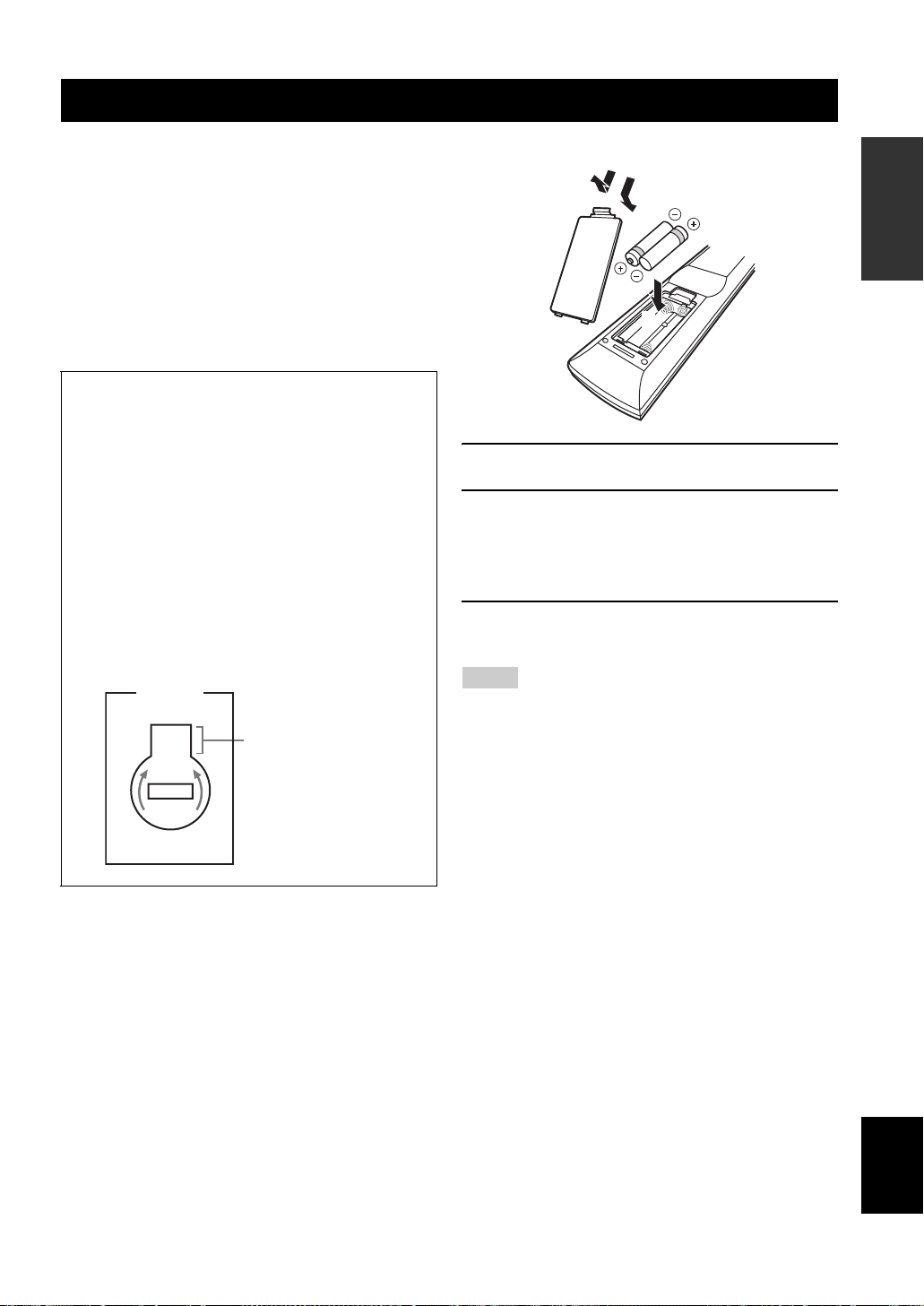
■ Installing batteries in the remote control
1
3
2
1 Take off the battery compartment cover.
2 Insert the two supplied batteries
(AAA, R03, UM-4) according to the polarity
markings (+ and –) on the inside of the
battery compartment.
3 Snap the battery compartment cover back
into place.
Notes
• Change all of the batteries if you notice that the operation range
of the remote control decreases.
• Do not use an old battery and a new one together.
• Do not use different types of batteries (such as alkaline and
manganese batteries) together. Read the packaging carefully as
these different types of batteries may have the same shape and
color.
• If the batteries have leaked, dispose of them immediately. Avoid
touching the leaked material or letting it come into contact with
clothing, etc. Clean the battery compartment thoroughly before
installing new batteries.
• Do not throw away batteries with general house waste; dispose
of them correctly in accordance with your local regulations.
• If the remote control is without batteries for more than 2
minutes, or if exhausted batteries remain in the remote control,
the contents of the memory may be cleared. When the memory
is cleared, insert new batteries and set up the remote control
code.
INTRODUCTION
3 En
English
Page 6

Quick start guide
Quick start guide
The following steps describe the easiest way to enjoy
DVD movie playback in your home theater.
Front right
Video monitor
Front left
speaker
Center speaker
DVD player
Step 1: Set up your speakers
Step 2: Connect your DVD player
speaker
Surround left
speaker
Subwoofer
Surround right
speaker
☞
P. 5
and other components
Preparation: Check the items
Prepare the following items.
❏ Speakers
❏ Front speaker .....................................x 2
❏ Center speaker ...................................x 1
❏ Surround speaker ..............................x 2
Select magnetically shielded speakers. The
minimum required speakers are two front speakers.
The priority of the requirement of other speakers is
as follows:
1. Two surround speakers
2. Center speaker
❏ Active subwoofer ...................................x 1
Select an active subwoofer equipped with an RCA
input jack.
❏ Speaker cable .........................................x 5
❏ Subwoofer cable .....................................x 1
Select a monaural RCA cable.
❏ DVD player ..............................................x 1
Select DVD player equipped with coaxial digital
audio output jack and composite video output
jack.
❏ Video monitor..........................................x 1
Select a TV monitor, video monitor or projector
equipped with a composite video input jack.
❏ Video cable .............................................x 2
Select an RCA composite video cable.
❏ Digital coaxial audio cable ....................x 1
Step 3: Press SCENE 1 button
Enjoy DVD playback!
4 En
☞
P. 6
☞
P. 7
Page 7

Step 1: Set up your speakers
Place your speakers in the room and connect them to this
unit.
SPEAKERS
COAXIAL
OPTICAL
DTV/CBL CD
DVD
1
2
VIDEO
OUTIN
OUT
DVD
P
RPBYPRPB
MONITOR OUT
MONITOR
OUT
CD
3
COMPONENT VIDEO ANTENNA
L
R
FRONT
MULTI CH INPUTAUDIO
DOCK
DTV/CBL
Y
DVR
CENTER
SUB
SUB
WOOFER
WOOFER
SUB
SURROUND
WOOFER
OUTPUT
OUTPUT
DTV/CBL
DVD
IN1 IN2
HDMI DIGITAL INPUT
VIDEO
L
R
MD/
OUT
IN
CD-R
(REC)
(PLAY)
OUT
DTV/CBL DVRDVD
IN
DTV/CBL DVRDVD
1 Place your speakers and subwoofer in the
room.
2 Connect speaker cables to each speaker.
SPEAKERS
AM
GND
FM
75
UNBAL.
LR
SURROUND
LR
SURROUND
LR
LR
LR
LR
FRONT B
FRONT ACENTER
FRONT B
FRONT ACENTER
Quick start guide
Be sure to connect the left channel (L), right channel
(R), “+” (red) and “–” (black) properly.
Front and center speakers
Loosen Insert Tighten
To the center
speaker
To the front
right speaker
To the front
left speaker
Surround speakers
INTRODUCTION
Cables are colored or shaped differently, perhaps with
a stripe, groove or ridge. Connect the striped
(grooved, etc.) cable to the “+” (red) terminals of
your speaker. Connect the plain cable to the “–”
(black) terminals.
3 Connect each speaker cable to the
corresponding speaker terminal of this unit.
12 3 4
1 Make sure that this unit and the subwoofer are
unplugged from the AC wall outlets.
2 Twist the exposed wires of the speaker cables
together to prevent short circuits.
3 Do not let the bare speaker wires touch each other.
4 Do not let the bare speaker wires touch any metal
part of this unit.
To the surround
right speaker
To the surround
left speaker
4 Connect the subwoofer cable to the input
jack of the subwoofer and the SUBWOOFER
OUTPUT jack of this unit.
Subwoofer
AV r eceive r
English
Input jack
Subwoofer cable
SUBWOOFER
OUTPUT jack
5 En
Page 8

Quick start guide
Step 2: Connect your DVD player
and other components
COAXIAL
COAXIAL
OPTICAL
OPTICAL
DTV/CBL CD
DVD
DTV/CBL CDDVD
1
2
3
2
3
1
DTV/CBL
OUT
DVD
IN1 IN2
HDMI DIGITAL INPUT
VIDEO
VIDEO
L
R
MD/
OUT
IN
CD-R
(REC)
(PLAY)
DIGITAL INPUT
COMPONENT VIDEO ANTENNA
DVD
P
RPBYPRPB
MONITOR OUT
VIDEO
VIDEO
MONITOR
MONITOR
OUTIN
OUTIN
DTV/CBL DVRDVD
DTV/CBL DVRDVD
OUT
OUT
L
R
IN
OUT
FRONT
CD
DTV/CBL DVRDVD
MULTI CH INPUTAUDIO
DOCK
DTV/CBL
Y
DVR
CENTER
SUB
WOOFER
SUB
SURROUND
WOOFER
OUTPUT
Make sure that this unit and the DVD
player are unplugged from the AC wall
outlets.
1 Connect the digital coaxial audio cable to the
digital coaxial audio output jack of your DVD
player and the DVD DIGITAL INPUT COAXIAL
jack of this unit.
DVD player
Digital coaxial
audio output jack
Digital coaxial audio
cable
2 Connect the video cable to the composite
video output jack of your DVD player and the
DVD VIDEO jack of this unit.
SPEAKERS
AM
GND
FM
75
UNBAL.
LR
SURROUND
LR
LR
FRONT B
FRONT ACENTER
AV receiver
DVD DIGITAL INPUT
COAXIAL jack
3 Connect the video cable to the video input
jack of your video monitor and the VIDEO
MONITOR OUT jack of this unit.
Video monitor
Video input
jack
Video cable
AV receiver
VIDEO MONITOR OUT
jack
4 Connect the power plug of this unit and other
components into the AC wall outlet.
■ For further connections
• Using the other kind of speaker
combinations ☞ P. 11
• Connecting video components ☞ P. 15
• Connecting a DVD player ☞ P. 16
• Connecting a DVD recorder ☞ P. 17
• Connecting a set-top box ☞ P. 17
• Connecting a CD player
and a CD recorder/MD recorder ☞ P. 18
• Connecting a multi-format player
or an external decoder ☞ P. 18
• Connecting a Yamaha iPod/Bluetooth dock
☞ P. 19
• Using the VIDEO AUX jacks on the front
panel ☞ P. 19
• Connecting an FM/AM antenna ☞ P. 20
• Using the USB jack on the front panel
☞ P. 49
Composite video
output jack
6 En
DVD player
Video cable
AV receiver
DVD VIDEO jack
Page 9

Step 3: Press SCENE 1 button
1 Turn on the video monitor and then set the
input source selector of the video monitor to
this unit.
2 Press
Q
SCENE 1.
This unit is turned on. “DVD Viewing” appears in the
front panel display, and this unit automatically
optimize own status for the DVD playback.
Quick start guide
■ About SCENE function
Just by pressing one SCENE button, you can turn on this
unit and recall your favorite input source and sound field
program according to the SCENE template that has been
assigned to the SCENE button. The SCENE templates are
built combinations of input sources and sound field
programs.
y
If you connect a Yamaha product that has capability of the
SCENE control signals, this unit can automatically activate the
component and start playback. Refer to the instruction manual of
the DVD player for further information.
■ The default assigned SCENE templates
INTRODUCTION
y
The indicator on the selected SCENE button lights up while
this unit is in the SCENE mode.
3 Start playback of the desired DVD on your
player.
4 Rotate
Note
When you change the input source or sound field program, the
SCENE mode is deactivated.
I
VOLUME to adjust the volume.
Default
SCENE
button
SCENE 1DVD Movie Viewing
SCENE 2Music Disc Listening
SCENE
3
SCENE
4
The name of the SCENE template
and its description
– input source: DVD
– sound field program: Movie Dramatic
For when you want to enjoy a movie from the
connected DVD player.
– input source: DVD
– sound field program: 2ch Stereo
For when you want to listen to a music disc from
the connected DVD player.
TV Viewing
– input source: DTV/CBL
– sound field program: STRAIGHT
For when you want to watch a TV program.
Radio Listening
– input source: TUNER
– sound field program: 5ch Enhancer
For when you want to listen to a music program
from the FM radio station.
*1
*2, *3, *4
Notes
*1
You must connect a cable TV or a satellite tuner to this unit in
advance. See page 17 for details.
*2
You need to connect the supplied FM and AM antennas to this
unit in advance. See page 20 for details.
*3
You must tune into the desired radio station in advance. See
pages 43 to 45 for tuning information.
*4
To achieve the best possible reception, orient the connected
AM loop antenna, or adjust the position of the end of the
indoor FM antenna.
y
You can change the assigned SCENE template for the SCENE
buttons. See page 28 for details.
7 En
English
Page 10

Quick start guide
■ After using this unit...
Press ASTANDBY/ON on the front panel to set
this unit to the standby mode.
This unit is set to the standby mode. In the standby mode,
this unit consumes a small amount of power in order to
receive infrared signals from the remote control. To turn
on this unit from the standby mode, press ASTANDBY/
ON (or GPOWER). See page 21 for details.
What do you want to do with this unit?
■ Customizing the SCENE templates
• Using various SCENE templates ☞ P. 28
• Creating your original SCENE templates
☞ P. 31
■ Using various input sources
• Basic controls of this unit ☞ P. 33
• Enjoying FM/AM radio programs ☞ P. 43
• Using your USB portable device
with this unit ☞ P. 49
• Using your iPod with this unit ☞ P. 51
• Using your Bluetooth components
with this unit ☞ P. 53
■ Using various sound features
• Using various sound field programs
☞ P. 38
• Using the direct mode for the high
quality sound ☞ P. 41
• Customizing the sound field programs
☞ P. 40
■ Adjusting the parameters of this unit
• Automatically optimizing the speaker
parameters for your listening room
(AUTO SETUP) ☞ P. 24
• Manually adjusting various parameters of
this unit ☞ P. 55
• Setting the remote control ☞ P. 67
• Adjusting the advanced parameters☞ P. 70
■ Additional features
Automatically turning off this unit ☞ P. 37
8 En
Page 11

Rear panel
A8 097
Connections
Connections
1
DTV/CBL
DVD
IN1 IN2
HDMI DIGITAL INPUT
L
R
MD/
IN
CD-R
(PLAY)
DTV/CBL DVRDVD
OUT
(REC)
DTV/CBL DVRDVD
OUT
VIDEO
IN
2 3 4 5
COAXIAL
DVD
1
DVD
MONITOR
OUTIN
OUT
OPTICAL
DTV/CBL CD
2
3
COMPONENT VIDEO ANTENNA
RPB
YPRPBY
P
MONITOR OUT
OUT
L
R
CD
CENTER
SUB
FRONT
SURROUND
WOOFER
MULTI CH INPUTAUDIO OUTPUT
DTV/CBL
DVR
Name Page
1 HDMI jacks 14
2 DIGITAL INPUT jacks 13
3 COMPONENT VIDEO jacks 13
4 DOCK terminal 19
5 Speaker terminals 11
6 VOLTAGE SELECTOR
(Asia and General models only)
7 AUDIO jacks 13
8 VIDEO jacks 13
9 MULTI CH INPUT jacks 18
0 SUBWOOFER OUTPUT jack 11
A ANTENNA terminals 20
6
SPEAKERS
DOCK
WOOFER
AM
GND
FM
75
UNBAL.
SUB
LR
FRONT ACENTER
SURROUND
FRONT B
LR
LR
3
PREPARATION
English
9 En
Page 12

Connections
Placing speakers
The speaker layout below shows the speaker setting we recommend. You can use it to enjoy CINEMA DSP and multichannel audio sources.
FL
SL
SL
C
30˚
60˚
80˚
FR
FL
SR
SR
FR
SW
C
SL
SR
Front left and right speakers (FL and FR)
The front speakers are used for the main source sound plus effect sounds. Place these speakers at an equal distance from the
ideal listening position. The distance of each speaker from each side of the video monitor should be the same.
Center speaker (C)
The center speaker is for the center channel sounds (dialog, vocals, etc.). If for some reason it is not practical to use a
center speaker, you can do without it. Best results, however, are obtained with the full system.
Surround left and right speakers (SL and SR)
The surround speakers are used for effect and surround sounds.
Subwoofer (SW)
The use of a subwoofer with a built-in amplifier, such as the Yamaha Active Servo Processing Subwoofer System, is
effective not only for reinforcing bass frequencies from any or all channels, but also for high fidelity sound reproduction
of the LFE (low-frequency effect) channel included in Dolby Digital and DTS sources. The position of the subwoofer is
not so critical, because low bass sounds are not highly directional. But it is better to place the subwoofer near the front
speakers. Turn it slightly toward the center of the room to reduce wall reflections.
10 En
Page 13

Connections
Connecting speakers
Be sure to connect the left channel (L), right channel (R), “+” (red) and “–” (black) properly. If the connections are faulty,
this unit cannot reproduce the input sources accurately.
Caution
• Before connecting the speakers, make sure that the AC power plug is disconnected from the AC wall outlet.
• Do not let the bare speaker wires touch each other or let them touch any metal part of this unit. This could damage
this unit and/or the speakers. If the speaker wires are short-circuited, “CHECK SP WIRES” appears in the front
panel display when you turn on this unit.
• Use the magnetically shielded speakers. If this type of speaker still creates interference with the monitor, place the
speakers away from the monitor.
Surround speakers
Right
Left
PREPARATION
DVD
DTV/CBL
IN1 IN2
HDMI DIGITAL INPUT
VIDEO
L
R
MD/
IN
CD-R
(PLAY)
DTV/CBL DVRDVD
OUT
(REC)
DTV/CBL DVRDVD
OUT
VIDEO
IN
COAXIAL
DVD
1
DVD
MONITOR OUT
MONITOR
OUTIN
OUT
OUT
CD
Subwoofer
OPTICAL
DTV/CBL CD
2
3
COMPONENT VIDEO ANTENNA
RPB
YPRPBY
P
L
R
FRONT
SURROUND
MULTI CH INPUTAUDIO
CENTER
WOOFER
DTV/CBL
DVR
SUB
OUTPUT
Center
speaker
DOCK
AM
GND
FM
75
UNBAL.
SUB
WOOFER
Right
Front speakers
(FRONT A)
FRONT ACENTER
Left
SPEAKERS
LR
SURROUND
FRONT B
LR
LR
FRONT B terminals
Connect the alternative front speaker system
(FRONT B).
11 En
English
Page 14

Connections
■ Before connecting to the SPEAKERS
terminal
A speaker cord is actually a pair of insulated cables
running side by side. Cables are colored or shaped
differently, perhaps with a stripe, groove or ridges.
Connect the striped (grooved, etc.) cable to the “+” (red)
terminals of this unit and your speaker. Connect the plain
cable to the “–” (black) terminals.
Remove approximately 10 mm (3/8”) of insulation
from the end of each speaker cable and then
twist the bare wires of the cable together to
prevent short circuits.
10 mm (3/8”)
■ Connecting to the SPEAKER terminals
2
1
Red: positive (+)
Black: negative (–)
3
1 Loosen the knob.
2 Insert the bare end of the speaker wire into
the hole on the terminal.
3 Tighten the knob to secure the wire.
Connecting the banana plug
(except Europe, Russia, Korea, and Asia models)
The banana plug is a single-pole electrical connector
widely used to terminate speaker cables. First, tighten the
knob and then insert the banana plug connector into the
end of the corresponding terminal.
Banana plug
12 En
Page 15

Connections
Information on jacks and cable plugs
Connect one of the type of the audio jack(s) and/or video jack(s) that your input components are equipped with.
Audio jacks and cable plugs Video jacks and cable plugs
AUDIO
L
L
Left and right
analog audio
cable plugs
R
(Red)(White) (Orange)
R
DIGITAL AUDIO
COAXIAL
C
Coaxial
digital audio
cable plug
DIGITAL AUDIO
OPTICAL
O
Optical
digital
audio cable
plug
■ Audio jacks
This unit has three types of audio jacks. Connection
depends on the availability of audio jacks on your other
components.
AUDIO jacks
For conventional analog audio signals transmitted via left
and right analog audio cables. Connect red plugs to the
right jacks and white plugs to the left jacks.
DIGITAL AUDIO COAXIAL jack
For digital audio signals transmitted via a coaxial digital
audio cable.
DIGITAL AUDIO OPTICAL jacks
For digital audio signals transmitted via optical digital
audio cables.
Notes
• You can use the digital jacks to input PCM, Dolby Digital and
DTS bitstreams. Optical input jacks are compatible with digital
signals with up to 96 kHz of sampling frequency.
• This unit handles digital and analog signals independently. Thus
audio signals input at the digital jacks are not output at the
analog AUDIO OUT (REC) jacks.
VIDEO
(Yellow)
V
Composite
video cable
plug
COMPONENT VIDEO
P
R
P
B
Y
(Red) (Blue) (Green)
PR
Component
video cable
plugs
PB
Y
■ Video jacks
This unit has two types of video jacks. Connection
depends on the availability of input jacks on your video
monitor.
VIDEO jacks
For conventional composite video signals transmitted via
composite video cables.
COMPONENT VIDEO jacks
For component signals, separated into the luminance (Y)
and chrominance (P
separate wires of component video cables.
Video signal flow for MONITOR OUT
COMPONENT
VIDEO
VIDEO
Note
The OSD signal is not output at the DVR OUT (REC) jacks.
B, PR) video signals transmitted on
Input
PR PB YPR PB Y
Output
(MONITOR OUT)
PREPARATION
13 En
English
Page 16

Connections
Information on HDMI™
■ HDMI compatibility with this unit
Audio signal
types
2ch Linear PCM 2ch, 32-192 kHz,
Multi-ch Linear
PCM
Bitstream Dolby Digital, DTS DVD-Video, etc.
Audio signal
formats
16/20/24 bit
8ch, 32-192 kHz,
16/20/24 bit
This unit’s HDMI interface is based on the following
standards:
• HDMI Version 1.2a (High-Definition Multimedia
Interface Specification Version 1.2a) licensed by
HDMI Licensing, LLC.
• HDCP (High-bandwidth Digital Content Protection
System) licensed by Digital Content Protection,
LLC.
Notes
• When CPPM copy-protected DVD audio is played back, video
and audio signals may not be output depending on the type of
the DVD player.
• This unit is not compatible with HDCP-incompatible HDMI or
DVI components.
• You can check the potential problem about the HDMI
connection (see page 36).
Compatible
HDMI
components
CD, DVD-Video,
DVD-Audio, etc.
DVD-Audio, etc.
■ HDMI jack and cable plug
HDMI
HDMI cable plug
y
• We recommend using an HDMI cable shorter than 5 meters (16
feet) with the HDMI logo printed on it.
• Use a conversion cable (HDMI jack
this unit to other DVI components.
Notes
• Do not disconnect or connect the cable or turn off the power of
the HDMI components connected to the HDMI OUT jack of
this unit while data is being transferred. Doing so may disrupt
playback or cause noise.
• Audio signals input at input jacks other than the HDMI IN DVD
or HDMI IN DTV/CBL jack of this unit cannot be digitally
output at the HDMI OUT jack.
• If you turn off the power of the video monitor connected to the
HDMI OUT jack via a DVI connection, this unit may fail to
establish the connection to the component.
↔ DVI-D jack) to connect
Audio and video signal flow
■ Audio signal flow
OutputInput
HDMI
AUDI O
Digital output
Analog output
Notes
• 2-channel as well as multi-channel PCM, Dolby Digital and
DTS signals input at the HDMI IN DVD or HDMI IN DTV/
CBL jack can be output at the HDMI OUT jack only when
“SUPPORT AUDIO” is set to “Other” (see page 61).
• Audio signals input at the HDMI IN jacks are not output at the
AUDIO output jacks.
14 En
■ Video signal flow
HDMI
COMPONENT
VIDEO
VIDEO
Through
OutputInput
Page 17

Connecting video components
O
Connections
Connect your TV (or projector) to the HDMI OUT jack,
the COMPONENT VIDEO MONITOR OUT jacks, or the
VIDEO MONITOR OUT jack of this unit.
Make sure that this unit and other
components are unplugged from the
AC wall outlets.
y
You can choose to play back HDMI audio signals on this unit or
on another HDMI component connected to the HDMI OUT jack
of this unit. Use the “SUPPORT AUDIO” parameter in “SOUND
MENU” to select the component to play back HDMI audio
signals (see page 61).
COAXIAL
DVD
1
DTV/CBL
D
IN1 IN2
HDMI
HDMI DIGITAL INPUT
/ -ROUT
(REC)
OUT
OUT
DVD
RPB
P
P
RPB
MONITOR OUT
MONITOR OUT
VIDEO
VIDEO
MONITOR
MONITOR
DTV/CBL DVRDVD
DTV/CBL DVRDVD
OUTIN
OUT
OUT
OUTIN
CD
Notes
• Some video monitors connected to this unit via a DVI
connection fail to recognize the HDMI audio/video signals
being input if they are in the standby mode. In this case, the
HDMI indicator flashes irregularly.
• When you connect your TV monitor or projector via HDMI
connection, the OSD does not appear. In such cases, connect the
TV monitor or projector via component, or video connection.
• Connect the input source components to the HDMI IN DVD or
HDMI IN DTV/CBL jack to display the video images on the
video monitor connected to the HDMI OUT jack.
OPTICAL
DTV/CBL CD
2
3
COMPONENT VIDEO
COMPONENT VIDEO
Y
YPRPBY
L
R
FRONT
SURROUND
MULTI CH INPUTAUDIO OUTPUT
CENTER
SUB
WOOFER
DTV/CBL
DVR
W
PREPARATION
HDMI in
PR PB
Component
video in
Y
V
TV (or projector)
indicates recommended connections
indicates alternative connections
Video in
English
15 En
Page 18

Connections
O
Connecting other components
Make sure that this unit and other
components are unplugged from the
AC wall outlets.
■ Connecting a DVD player
L
L
R
R
(PLAY)
HDMI out
Video out
Audio out
LR
V
DTV/CBL
DVD
IN1 IN2
DVD
IN1
HDMI DIGITAL INPUT
HDMI DIGITAL INPUT
VIDEO
DVD
MD/
OUT
IN
CD-R
(REC)
DVD
AUDIO
OUT
DTV/CBL DVRDVD
IN
DTV/CBL DVRDVD
Notes
• Be sure to make the same type of video connections as those
made for your TV (see page 15).
• To make a digital connection to a component other than the
default component assigned to DIGITAL INPUT jack, select
the corresponding setting for “OPTICAL IN” or “COAXIAL
IN” in “INPUT ASSIGNMENT” (see page 62).
DVD player
Component
video out
Coaxial out
PR PB Y
OPTICAL
DTV/CBL CD
2
3
COMPONENT VIDEO
COMPONENT VIDEO
YPRPBY
Y
L
R
FRONT
SURROUND
MULTI CH INPUTAUDIO
CENTER
SUB
WOOFER
DTV/CBL
DVR
W
OUTPUT
VIDEO
VIDEO
C
COAXIAL
COAXIAL
DVD
DVD
1
1
DVD
DVD
RPB
P
RPB
P
MONITOR OUT
MONITOR
OUTIN
OUT
OUT
CD
16 En
indicates recommended connections
indicates alternative connections
(One for the video connection,
and one for the audio connection)
Page 19

■ Connecting a DVD recorder, PVR or VCR
O
DTV/CBL CD
DVD
O
Connections
DTV/CBL
DVD
IN1 IN2
HDMI DIGITAL INPUT
VIDEO
VIDEO
DTV/CBL DVRDVD
L
L
R
R
MD/
OUT
IN
CD-R
(REC)
(PLAY)
DTV/CBL DVRDVD
AUDIO
Audio out
V
R
■ Connecting a set-top box
Satellite receiver, cable TV
receiver or HDTV decoder
RPB
P
MONITOR OUT
OUT
CD
L
COMPONENT VIDEO
COMPONENT VIDEO
L
R
V
Video in
FRONT
2
3
YPRPBY
RPB
P
CENTER
SUB
SURROUND
WOOFER
MULTI CH INPUTAUDIO
DTV/CBL
Y
DVR
DVR
OUTPUT
W
PR PB Y
PREPARATION
1
OUT
DVD
VIDEO
VIDEO
MONITOR
OUTIN
OUTIN
DVR
IN
OUT
IN
OUT
DVR
Audio in
R
L
Component video out
Video out
DVD recorder,
PVR or VCR
L
L
R
R
(PLAY)
HDMI out Component video out
Video out
V
DTV/CBL
DTV/CBL
DVD
IN1 IN2
HDMI DIGITAL INPUT
HDMI DIGITAL INPUT
VIDEO
VIDEO
MD/
OUT
IN
CD-R
(REC)
AUDIO
IN2
DTV/CBL
DTV/CBL DVRDVD
DTV/CBL
DTV/CBL DVRDVD
OUT
IN
L R
VIDEO
VIDEO
Audio out
OUTIN
OUT
COAXIAL
DVD
1
DVD
MONITOR OUT
MONITOR
OUT
CD
RPB
P
Optical out
O
OPTICAL
OPTICAL
DTV/CBL CD
DTV/CBL
2
2
COMPONENT VIDEO
COMPONENT VIDEO
YPRPBY
L
R
FRONT
MULTI CH INPUTAUDIO
3
SURROUND
RPB
P
CENTER
WOOFER
PR PB Y
DTV/CBL
DTV/CBL
Y
DVR
indicates recommended
connections
OUTPUT
W
indicates alternative
connections (One for the video
SUB
English
connection, and one for the
audio connection)
17 En
Page 20

Connections
W
U
Connecting audio components
Connect the audio components as follows.
■ Connecting a CD player and a CD
recorder/MD recorder
Notes
• When you connect your CD player via analog and digital
connection, priority is given to the signal input at the DIGITAL
INPUT jack.
• To make a digital connection to a component other than the
default component assigned to each DIGITAL INPUT jack,
select the corresponding setting in “INPUT ASSIGNMENT”
(see page 62).
Make sure that this unit and other
components are unplugged from the
AC wall outlets.
indicates recommended connections
indicates alternative connections
R
L
Audio in
CD recorder or
MD recorder
L
R
Audio out
L
L
R
R
DTV/CBL
IN1 IN2
HDMI DIGITAL INPUT
VIDEO
DTV/CBL DVRDVD
MD/
OUT
IN
MD/
OUT
IN
CD-R
(REC)
(PLAY)
CD-R
(REC)
(PLAY)
AUDIO
AUDIO
DTV/CBL DVRDVD
COAXIAL
DVD
1
OUTDVD
DVD
MONITOR OUT
VIDEO
MONITOR
OUTIN
OUT
IN
OUT
CD
CD
DIGITAL INPUT
RPB
P
OPTICAL
OPTICAL
DTV/CBL CD
2
COMPONENT VIDEO
YP
L
R
FRONT
MULTI CH INP
CD
3
3
SURROUND
R
L
R
Audio out
O
Optical out
CD player
■ Connecting a multi-format player or an external decoder
This unit is equipped with 6 additional input jacks (FRONT L/R, SURROUND L/R, CENTER and SUBWOOFER) for
discrete multi-channel input from a multi-format player, external decoder or sound processor. Connect the output jacks
on your multi-format player or external decoder to the MULTI CH INPUT jacks. Be sure to match the left and right
output jacks to the left and right input jacks for the front and surround channels.
Notes
• When you select the component connected to the MULTI CH INPUT jacks as the input source (see page 34), this unit automatically
turns off the digital sound field processor, and you cannot select sound field programs.
• This unit does not redirect signals input at the MULTI CH INPUT jacks to accommodate for missing speakers. We recommend that
you connect a 5.1-channel speaker system before using this feature.
FRONT
MULTI CH INPUT
Surround out
SURROUND
CENTER
WOOFER
SUB
Subwoofer out
Center out
L
R
L R LR
Front out
18 En
Multi-format player/
External decoder
Page 21

Connections
Connecting a Yamaha iPod™
universal dock or Bluetooth
™
adapter
Make sure that this unit and other
components are unplugged from the
AC wall outlets.
This unit is equipped with the DOCK terminal on the rear
panel that allows you to connect a Yamaha iPod universal
dock (such as YDS-10, sold separately) or Bluetooth
adapter (such as YBA-10, sold separately). Connect a
Yamaha iPod universal dock or Bluetooth adapter to the
DOCK terminal on the rear panel of this unit using its
dedicated cable.
DOCK
DOCK
DTV/CBL
B
Y
P
ANTENNA
DVR
AM
GND
Using the VIDEO AUX jacks on the front panel
Use the VIDEO AUX jacks on the front panel to connect a
game console or a video camera to this unit.
Caution
Be sure to turn down the volume of this unit and other
components before making connections.
Notes
• To reproduce the source signals input at these jacks, select
“V-AUX” as the input source.
• When audio signals are input at the AUDIO jacks and the
DOCK terminal on the rear panel, the priority order of the input
signal is as follows:
1. DOCK
2. AUDIO
VOLUME
SILENT CINEMA
STANDBY/
ON
PHONES
EDIT
BAND
A/B/C/D/E
PRESET/TUNING
SPEAKERS
TONE CONTROL
A/B/OFF
l
PRESET/TUNING/CH
SCENE
1234
DIRECTSTRAIGHT
EFFECT
VIDEO AUX
VIDEO L AUDIO R
OPTIMIZER MIC
h
MEMORY
TUNING AUTO/MAN'L
l INPUT hl PROGRAM h
AUDIO SELECT
VIDEO AUX USB
VIDEO L AUDIO R
PREPARATION
Yamaha iPod universal dock
or Bluetooth adapter
V
L
Vid eo
output
Game console or
video camera
R
Audio
output
English
19 En
Page 22

Connections
R
Connecting the FM and AM antennas
Both FM and AM indoor antennas are supplied with this
unit. Connect each antenna correctly to the designated
terminals. In general, these antennas should provide
sufficient signal strength.
y
See right for connection information of the supplied AM loop
antenna.
Notes
• The AM loop antenna should be placed away from this unit.
• The AM loop antenna should always be connected, even if an
outdoor AM antenna is connected to this unit.
• A properly installed outdoor antenna provides clearer reception
than an indoor one. If you experience poor reception quality,
install an outdoor antenna. Consult the nearest authorized
Yamaha dealer or service center about outdoor antennas.
Outdoor AM antenna
Use a 5 to 10 m (16 to 33
ft) vinyl-covered wire
extended outdoors from a
window.
DOCK
ANTENNA
ANTENNA
AM
AM
GND
GND
FM
FM
75
75
UNBAL.
UNBAL.
AM loop
antenna
(supplied)
Indoor FM
antenna
(supplied)
Connecting the wire of the AM loop antenna
Open the lever
Insert
Close the lever
y
The wire of the AM loop antenna does not have any polarity
and you can connect either end of the wire to AM or GND
terminal.
Assembling the supplied AM loop antenna
Note
The types of the supplied AM loop antenna is different
depending on the models.
Connecting the power cable
Once all connections are complete, plug the power cable
into the AC wall outlet.
SUB
WOOFER
CENTE
PUT
(U.S.A. model)
Ground (GND terminal)
For maximum safety and minimum interference, connect the
GND terminal to a good earth ground. A good earth
antenna
ground is a metal stake driven into moist earth.
20 En
Power cable
Page 23

Turning on and off the power
■ Turning on this unit
Press ASTANDBY/ON (or GPOWER) to turn
on this unit.
y
When you turn on this unit, there will be a 4 to 5-second delay
before this unit can reproduce sound.
■ Set this unit to the standby mode
Press ASTANDBY/ON (or HSTANDBY) to set
this unit to the standby mode.
In the standby mode, this unit consumes a small amount of
power in order to receive infrared signals from the remote
control.
Connections
PREPARATION
21 En
English
Page 24

Connections
Front panel display
23 456 7
DVR
V-A UX
DOCK ENHANCER
SP
AB
DTV/CBL
SILENT
CINEMA
USB
PCM
1
MULTI CH
q
q
DIGITAL
PL
1 HDMI indicator
Lights up when the signal of the selected input source is
input at the HDMI IN jacks (see page 14).
2 DOCK indicator
• Lights up when you station your iPod in a Yamaha
iPod universal dock (such as YDS-10, sold separately)
connected to the DOCK terminal of this unit (see
page 19) and V-AUX is selected as the input source.
• Flashes while the connected Yamaha Bluetooth adapter
(such as YBA-10, sold separately) and the Bluetooth
component is in the paring (see page 53) or the
Bluetooth adapter is searching the Bluetooth
component (see page 53).
• Lights up while the connected Yamaha Bluetooth
adapter is connected to the Bluetooth component (see
page 19).
3 ENHANCER indicator
Lights up when the Compressed Music Enhancer mode is
selected (see page 38).
4 Input source indicators
The corresponding cursor lights up to show the currently
selected input source.
5 YPAO indicator
Lights up when you run “AUTO SETUP” and when the
speaker settings set in “AUTO SETUP” are used without
any modifications (see page 24).
DVD CD
MD/CD-R
SLEEP
YPAO
VIRTUAL
MEMORY
AUTO
TUNER
TUNED
STEREO
EONCTRTPTYPSHOLDPTY
VOL.
MUTE
ft
ms
dB
LFE
LL C R
SL SR
FD ECA B098
6 Tuner indicators
Lights up when this unit is in the FM or AM tuning mode
(see pages 43 to 45).
7 MUTE indicator and VOLUME level indicator
• The MUTE indicator flashes while the MUTE function
is on (see page 35).
• Indicates the current volume level.
8 PCM indicator
Lights up when this unit is reproducing PCM (Pulse Code
Modulation) digital audio signals.
9 Decoder indicators
The respective indicator lights up when any of the
decoders of this unit function.
0 Headphone indicator
Lights up when headphones are connected (see page 35).
A SP A B indicators
Light up according to the set of front speakers activated
(see page 33).
SP A: The FRONT A speakers are activated.
SP B: The FRONT B speakers are activated.
dB
22 En
Page 25

Connections
B CINEMA DSP indicator
Lights up when you select a CINEMA DSP sound
field program (see page 39).
VIRTUAL indicator
Lights up when Virtual CINEMA DSP is active (see
page 39).
SILENT CINEMA indicator
Lights up when headphones are connected and a
sound field program is selected (see page 39).
C Multi-information display
Shows the name of the current sound field program and
other information when adjusting or changing settings.
D SLEEP indicator
Lights up while the sleep timer is on (see page 37).
E Radio Data System indicators
(Europe and Russia models only)
PTY HOLD
Lights up while searching for the Radio Data System
stations in the PTY SEEK mode.
PS, PTY, RT and CT
Light up according to the selected Radio Data System
display mode.
EON
Lights up when the EON data service is being
received.
F Input channel and speaker indicators
LFE
LL C R
SL SR
LFE indicator
Input channel indicators
■ Using the remote control
The remote control transmits a directional infrared ray.
Be sure to aim the remote control directly at the remote
control sensor on this unit during operation.
Approximately 6 m (20 ft)
1 Infrared window
Outputs infrared control signals. Aim this window at the
component you want to operate.
y
To set the remote control codes for other components, see
page 69.
Notes
• Do not spill water or other liquids on the remote control.
• Do not drop the remote control.
• Do not leave or store the remote control in the following types
of conditions:
– places of high humidity, such as near a bath
– places of high temperature, such as near a heater or stove
– places of extremely low temperatures
– dusty places
30º 30º
PREPARATION
Input channel indicators
• Indicate the channel components of the current
digital input signal.
• Light up or flash according to the settings of the
speakers when this unit is in the automatic setup
procedure (see page 24) or the speaker level setting
procedure in the “SP LEVEL” (see page 59).
English
23 En
Page 26

Optimizing the speaker setting for your listening room
Optimizing the speaker setting for your listening room
This unit employs the YPAO (Yamaha Parametric Room Acoustic Optimizer) technology which lets you avoid
troublesome listening-based speaker setup and achieves highly accurate sound adjustments automatically. The supplied
optimizer microphone collects and this unit analyzes the sound your speakers produce in your actual listening
environment.
Using AUTO SETUP
Notes
• Be advised that it is normal for loud test tones to be output
during the “AUTO SETUP” procedure.
• To achieve the best results, make sure the room is as quiet as
possible while the “AUTO SETUP” procedure is in progress. If
there is too much ambient noise, the results may not be
satisfactory.
y
You can run “AUTO SETUP” using the system menu that
appears in the OSD or in the front panel display. This manual uses
the OSD illustrations to explain the “AUTO SETUP” procedure.
1 Make sure of the following check points.
Note
Before starting the automatic setup, check the following
check points.
❏ Speakers are connected appropriately.
❏ Headphones are disconnected from this unit.
❏ This unit and the video monitor are turned on.
❏ This unit is selected as the video input source of
the video monitor.
❏ The connected subwoofer is turned on and the
volume level is set to about half way (or slightly
less).
❏ The crossover frequency controls of the
connected subwoofer is set to the maximum.
VOLUME
CROSSOVER
HIGH CUT
2 Connect the supplied optimizer microphone
to the OPTIMIZER MIC jack on the front
panel.
OPTIMIZER MIC
TUNING AUTO/MAN'L
VIDEO AUX USB
AUDIO SELECT
VIDEO L AUDIO R
Optimizer
microphone
The following display appears in the OSD.
AUTO SETUP
SETUP;;;;;;;AUTO
. START
Automatic
Processing
of all item
p
[ ]/[ ]:Up/Down
p
[ENTER]:Start
3 Place the optimizer microphone at your
normal listening position on a flat level
surface with the microphone heading
upward.
Optimizer microphone
MIN
MAX
Controls of a subwoofer (example)
MIN MAX
❏ FRONT A speakers are selected as the front
speaker system (see page 33).
❏ The room is sufficiently quiet.
24 En
y
It is recommended that you use a tripod (etc.) to affix the
optimizer microphone at the same height as your ears would be
when you are seated in your listening position. You can use the
attached screw of a tripod (etc.) to fix the optimizer microphone
to the tripod (etc.).
Page 27

Optimizing the speaker setting for your listening room
4 Make sure that “SETUP” is set to “AUTO”
and the pointer is pointing at “START”.
y
You can also select the following setup methods. In this
7
case, press
select the one of the following choices and then select
“START”.
k to select “SETUP”, press
Choices: AUTO, RELOAD, UNDO, DEFAULT
• Select “AUTO” to automatically run the entire
“AUTO SETUP” procedure.
• Select “RELOAD” to reload the last “AUTO
SETUP” settings and override the previous
settings.
• Select “UNDO” to undo the last “AUTO SETUP”
settings and restore the previous settings.
• Select “DEFAULT” to reset the “AUTO SETUP”
parameters to the initial factory settings.
Note
“RELOAD” or “UNDO” is available only when you have
previously run “AUTO SETUP” and confirmed the results.
5 Press
7
n to select “START” and then press
7
ENTER to start the setup procedure.
The following message appears in the OSD.
7
l / h to
6 Press
7
ENTER to start the setup
procedure.
This unit starts the auto setup procedure. Loud test
tones are output from each speaker during the auto
setup procedure. Once all items are set, the result
display appears in the OSD.
Notes
• During the auto setup procedure, do not perform any
operation on this unit.
• We recommend getting out of the room while this unit is in
the auto setup procedure. It takes approximately 3 minutes
for this unit to complete the auto setup procedure.
This unit performs the following checks:
Speaker wiring/volume level WIRING/LEVEL
Checks which speakers are connected and the
polarity of each speaker. Also checks and adjusts the
volume level of each speaker.
Speaker distance DISTANCE
Checks the distance of each speaker from the
listening position and adjusts the timing of each
channel.
PREPARATION
NOTICE
Loudtesttonesare
output.
Pleasekeepquiet
orleavetheroom.
Press[ENTER]
Before proceeding next operation
Once you perform the next operation, this unit starts the
automatic setup procedure. For more accurate
measurements, keep quiet and move to the wall where
speakers are not around. We recommend that you leave
the listening room during the automatic setup
procedure.
Speaker size SIZE
Checks the frequency response of each speaker and
sets the appropriate low-frequency crossover for each
channel.
English
25 En
Page 28

Optimizing the speaker setting for your listening room
The display changes as follows.
AUTO SETUP
SETUP;;;;;;;AUTO
. START
Automatic
Processing
of all item
p
[ ]/[ ]:Up/Down
p
[ENTER]:Start
7 Press
7
k and 7ENTER to display the
setup results in detail.
8 Press
7
l / h repeatedly to toggle between
the setup result displays.
Results of the speaker
connection and wiring
AUTO SETUP
INITIALIZING
. WIRING/LEVEL
DISTANCE
SIZE
WAITING;;;
;;;;;;;;;;
[
[]:Exit
AUTO SETUP
RESULT
SP : 3/2/0.1
DIST: 3.2/3.5m
LVL : -2/+2dB
. SET CANCEL
>
[ ]/[ ]:Up/Down
[ENTER]:Enter
The results displayed under “RESULT” are as follows.
Number of speakers SP
Displays the number of speakers connected to this unit in
the following order:
Front/Back/Subwoofer
Speaker distance DIST
Displays the speaker distance from the listening position
in the following order:
Closest speaker distance/Farthest speaker distance
Speaker level LVL
Displays the speaker output level in the following order:
Lowest speaker output level/Highest speaker output level
Results of the speaker
distance from the
listening position
Results of the speaker
size
Results of the speaker
output level
y
If you are not satisfied with the results or want to manually
adjust each parameter, run “MANUAL SETUP” (see
page 55).
Note
The distances displayed in the “DISTANCE” results may be
longer than the actual distance depending on the
characteristics of your speakers.
9 Press
7
ENTER to return to the result
display.
AUTO SETUP
Notes
• If “E-9:INTERNAL ERROR” appears during the testing
procedure, restart from step 4.
• If you selected “RELOAD” in step 4, no test tones are output.
• If an error occurs during the “AUTO SETUP” procedure, the
setup procedure is canceled and an error screen appears. For
details, see “If an error screen appears” on page 27.
• When this unit detects potential problems during the “AUTO
SETUP” procedure, “WARNING” and the number of warning
messages appears (see page 27).
26 En
. RESULT
SP : 3/2/0.1
DIST: 3.2/3.5m
LVL : -2/+2dB
SET CANCEL
>
[ ]/[ ]:Up/Down
[ENTER]:Detail
Page 29
10 Press
7
n and then press 7l / h to select
“SET” or “CANCEL”.
Choices: SET, CANCEL
• Select “SET” to confirm the “AUTO SETUP”
results.
• Select “CANCEL” to cancel the “AUTO SETUP”
results.
11 Press
7
ENTER to confirm your selection.
The top “SET MENU” display appears in the OSD.
SET MENU
TOP MENU
.;AUTO SETUP
;MANUAL SETUP
.A;SIGNAL INFO
p
[ ]/[ ]:Up/Down
p
[ENTER]:Enter
12 Press
K
MENU to exit from “SET MENU”.
13 Disconnect the optimizer microphone from
this unit.
The optimizer microphone is sensitive to heat. Keep
it away from direct sunlight and do not place it on top
of this unit.
y
If you change speakers, speaker positions, or the layout of your
listening environment, run “AUTO SETUP” again to recalibrate
your system.
■ If an error screen appears
Press 7k / n / l / h to select “RETRY” or
“EXIT” and then press 7ENTER.
The following display is an example where “E-8:USER
CANCEL” appears in the OSD.
ERROR
. E-8:USER CANCEL
Can't detect
signal at MIC
RETRY EXIT
>
[ ]/[ ]:Select
[ENTER]:Enter
Choices: RETRY, EXIT
• Select “RETRY” to retry the “AUTO SETUP”
procedure.
• Select “EXIT” to exit from the “AUTO SETUP”
procedure.
Optimizing the speaker setting for your listening room
■ If “WARNING” appears
When this unit detects potential problems during the
“AUTO SETUP” procedure, “WARNING” appears in the
result display. Check the warning messages to correct your
speaker settings.
Note
Warnings differ from errors in that warnings do not cancel the
“AUTO SETUP” procedure.
1 Make sure the pointer is pointing at
“WARNING” and then press 7ENTER to
display the detailed information about the
warning.
The number on the right of “WARNING” indicates
the number of warning messages.
AUTO SETUP
. WARNING(2)
RESULT
SP : 3/2/0.1
DIST: 3.2/3.5m
LVL : -2/+2dB
SET CANCEL
>
[ ]/[ ]:Up/Down
[ENTER]:Detail
2 Press
3 Press
7
l / h repeatedly to toggle between
the warning displays.
WARNING
W-1:OUT OF PHASE
Reverse channel
AAAAFLAAAAA---
AAACENTER
AAAASLAAAAA---
[ ]/[ ]:Select
[ENTER]:Return
y
• For details about each warning message, see the “AUTO
SETUP” section in “Troubleshooting” on page 75.
• When the corresponding warning message is not
applicable to a speaker, “–
7
ENTER to return to the result
– –” is displayed instead.
display.
PREPARATION
27 En
English
Page 30

SELECTING THE SCENE TEMPLATES
Selecting the SCENE templates
This unit is equipped with 16 preset SCENE templates for
various situations of using this unit. As the initial factory
setting, the following SCENE templates are assigned to
each SCENE button:
2 Press
O
INPUT l / h (or press 4AMP and
then press 7l / h) to select the desired
template.
SCENE 1: DVD Movie Viewing
SCENE 2: Music Disc Listening
SCENE 3: TV Viewing
SCENE 4: Radio Listening
If you want to use other SCENE templates, you can select
the desired SCENE templates from the SCENE template
library and assign the templates to the selected SCENE
buttons on the front panel and the remote control.
Select the desired SCENE
SCENE template library
template
(Image)
1
Assign the
SCENE
template to the
SCENE button
Selecting the desired SCENE template
l INPUT h
Front panel
or
AMP
ENTER
Remote control
DVD Viewing
3 Press the QSCENE (or
again to confirm the selection.
The selected SCENE template is assigned to the
button.
1
5
SCENE) button
or
1
1 Press and hold the desired QSCENE (or
5
SCENE) button for 3 seconds.
The indicator on the selected SCENE button on the
front panel starts to flash, and the name of the
currently assigned SCENE template appears in the
front panel display.
3 seconds
1
Front panel
or
1
Flashes
3 seconds
1
Remote control
DVD MovieView
28 En
Remote controlFront panel
Note
Once the desired SCENE templates are assigned to the
corresponding SCENE buttons, you may need to set the input
source of the SCENE template on the remote control. See page 32
for details.
Page 31

■ Which SCENE template would you like to select?
Selecting the SCENE templates
Which source do you like to
play back?
Video sources
(DVD video,
Recorded video)
Music discs (CD, SACD
or DVD-Audio)
Radio programs
Which component do you
like for playback?
DVD
DVR
DVD
CD
TUNER (FM/AM)
SCENE templates
DVD Viewing
DVD Movie Viewing
DVD Live Viewing
DVR Viewing
Disc Hi-fi Listening
Music Disc Listening
Disc Listening
CD Hi-fi Listening
CD Listening
CD Music Listening
Radio Listening
Default
SCENE buttons
1
2
OPERATION
BASIC
4
iPod or Bluetooth
component
USB memory device
or USB portable
audio player
TV programs
Video games
DOCK
USB
DTV/CBL
V-AUX
*
Dock Listening
USB Audio Listening
TV Viewing
TV Sports Viewing
Game Playing
3
Note
* When iPod is connected to the Yamaha iPod universal dock or a Bluetooth component is connected to the Bluetooth adapter, this unit
plays back the audio sources input at the DOCK terminal.
y
You can create your original SCENE templates by editing the preset SCENE templates. See page 31 for details.
English
29 En
Page 32

Selecting the SCENE templates
■ Preset SCENE templates descriptions
The illustrations of the SCENE button in the following table indicate the assigned SCENE buttons in the default setting.
SCENE template Input source Playback mode Features
DVD Viewing
DVD Movie Viewing
1
DVD STRAIGHT
DVD MOVIE
Movie Dramatic
Select this SCENE template when you play back general
contents on the DVD player.
Select this SCENE template when you play back movies on
your DVD player.
DVD Live Viewing
DVR Viewing
Disc Hi-fi Listening
Music Disc
Listening
2
Disc Listening
CD Hi-fi Listening
CD Listening
CD Music Listening
Radio Listening
4
Dock Listening
USB Audio
Listening
TV Viewing
3
DVD MUSIC
Pop/Rock
DVR MOVIE
Movie Dramatic
DVD DIRECT
DVD STEREO
2ch Stereo
DVD STEREO
5ch Stereo
CD DIRECT
CD STEREO
5ch Stereo
CD STEREO
2ch Stereo
TUNER MUSIC ENHANCER
5ch Enhancer
DOCK MUSIC ENHANCER
5ch Enhancer
USB MUSIC ENHANCER
5ch Enhancer
DTV/CBL STRAIGHT
Select this SCENE template when you enjoy the music live
video on your DVD player.
Select this SCENE template when you play back movies on
your digital video recorder.
Select this SCENE template when you enjoy the high fidelity
sound of the music discs on your DVD player.
Select this SCENE template when you play back music discs
on your DVD player.
Select this SCENE template when you play back music
sources on your DVD player as the background music.
Select this SCENE template when you enjoy the high fidelity
sound of the music discs on your CD player.
Select this SCENE template when you play back music discs
on your CD player as the background music.
Select this SCENE template when you play back music source
on your CD player.
Select this SCENE template when you enjoy FM or AM radio
programs.
Select this SCENE template when you play back music on
your iPod stationed in a Yamaha iPod universal dock or
Bluetooth component that is connected to the Bluetooth
adapter.
Select this SCENE template when you play back music on
your USB memory device or a USB portable audio player.
Select this SCENE template when you enjoy general
programs on your TV.
TV Sports Viewing
Game Playing
30 En
DTV/CBL ENTERTAINMENT
TV Sports
V-AUX ENTERTAINMENT
Game
Select this SCENE template when you enjoy sports programs
on your TV.
Select this SCENE template when you play video games.
Page 33

Selecting the SCENE templates
Creating your original SCENE templates
You can create your original SCENE templates for each
SCENE button. You can refer to the preset 16 SCENE
templates to create the original SCENE templates.
■ Customizing the preset SCENE
templates
Use this feature to customize the preset SCENE templates.
Select a SCENE template
SCENE template library
(Image)
Create the original SCENE
template
SCENE : DVD Viewing
: DVD
INPUT
: DVD Viewing
SCENE
1
Assign to the SCENE
button
3 Press
4
AMP and then 7k / n to select the
desired parameter of the SCENE template
and then 7l / h to select the desired value
of the selected parameter.
You can adjust the following parameters for a
SCENE template:
• INPUT: The input source component
• MODE: The active sound field programs,
STRAIGHT or DIRECT mode (see
pages 39 and 41)
• NIGHT: The night listening mode setting (see
page 42)
− SYSTEM: Keeps the current night listening
mode.
− CINEMA: Sets the night listening mode to the
CINEMA mode.
− MUSIC: Sets the night listening mode to the
MUSIC mode.
4 Press the
5
SCENE button again to confirm
the edit.
1
OPERATION
BASIC
1 Turn on the video monitor connected to this
unit.
2 Press and hold the desired
for 3 seconds.
The SCENE template customizing screen appears on
the video monitor.
1
3 seconds
Note
When the SCENE template you want to customize is not
assigned to any of the 5SCENE buttons, press 4AMP
and then press 7l / h repeatedly to recall the desired
SCENE template on the menu screen.
5
SCENE button
y
An asterisk mark (*) appears by the name of the original SCENE
template.
Notes
• Once the desired SCENE templates are assigned to the
corresponding 5SCENE buttons, you may need to set the
input source of the SCENE template on the remote control. See
page 32 for details.
• You can create a customized SCENE template for each
5
SCENE button, and if you create another customized
SCENE template, this unit overwrites the old customized
SCENE template with the new one.
• The newly created template is only available for the assigned
5
SCENE button.
■ Renaming the SCENE templates
Select the name of the SCENE template at step 3
of “Customizing the preset SCENE templates”
and then press 7ENTER.
• Press 7k / n to select the desired character.
•Press 7l / h to place “_” (underscore) under the
space or the desired character.
• Press 8RETURN to cancel the new name.
• Press 7ENTER to confirm the new name.
English
31 En
Page 34

Selecting the SCENE templates
Using remote control on the SCENE feature
■ Controlling the input source
components in the SCENE mode
You can operate both this unit and the input source
component by using the remote control. You must set the
appropriate remote control code for each input source in
advance (see page 69).
1 Press the desired
5
SCENE button on the
remote control.
2 Press the desired buttons in the * area below
to control the input source component of the
selected SCENE template.
POWER
STANDBY
POWER
POWER
AVTV
USB
A B
DTV/CBL DVR
C D
BC
TV INPUT
SCENE
ENTER
TV MUTE
SRCH MODE
MENU
DISPLAY
MODE - PTY SEEK - START
ENHANCER
NIGHT
MUTE
TV CH
TV VOL
VOLUME
SUR. DECODE
PARAMETER
SLEEP
ENT
4321
4321
81070965
SCENE buttons
CD MD/CD-R TUNER
DVD
V-AUX/DOCK
AMP
*
BAND LEVEL
TITLE
RETURN
MEMORY
REC
FREQ/TEXT EON
l PROG h
STRAIGHT DIRECT
MULTI CH IN AUDIO SEL
■ Setting input source of the customized
SCENE template on the remote control
If you customize the input source of the selected SCENE
template, you must set the input source of the SCENE
template on the remote control to operate the input source
component correctly.
Press and hold the 5SCENE button and the
desired input selector button (3) for 3 seconds.
y
Press the 5SCENE button again to operate the input source
component.
Note
*
These buttons control the input source component. See page 68
for details of the function of each button.
32 En
Page 35

Playback
PLAYBACK
Caution
Extreme caution should be exercised when you play
back CDs encoded in DTS. If you play back a CD
encoded in DTS on a DTS-incompatible CD player,
you will only hear some unwanted noise that may
damage your speakers. Check whether your CD player
supports CDs encoded in DTS. Also, check the sound
output level of your CD player before you play back a
CD encoded in DTS.
Basic operations
1 Turn on the video monitor connected to this
unit.
2 Press
3 Press
4 Start playback on the selected component or
J
SPEAKERS repeatedly to select the
front speakers you want to use.
The respective speaker indicators lights up in the
front panel display.
O
INPUT l / h repeatedly (or press
one of the input selector buttons (3)) to
select the desired input source.
The name of the currently selected input source
appears in the front panel display for a few seconds.
Available input sources
MULTI CH
DVR
V-AUX
DTV/CBL
DVD CD
MD/CD-R
USB
TUNER
INPUT:DVD
Currently selected input
source
select a broadcast station.
• Refer to the operating instructions for the source
component.
• See page 43 for details about FM/AM tuning
instructions.
5 Rotate
I
VOLUME (or press
LVOLUME +/–) to adjust the volume to the
desired output level.
6 Press
L
PROGRAM l / h repeatedly (or
press 4AMP and then APROG l / h
repeatedly) to select the desired sound field
program.
The name of the selected sound field program appears
in the front panel display.
See page 38 for details about sound field programs.
Movie Dramatic
Currently selected
surround field program
Notes
• Choose a sound field program based on your listening
preference, not merely on the name of the program.
• When you select an input source, this unit automatically selects
the last sound field program used with the corresponding input
source.
• Sound field programs cannot be selected when the component
connected to the MULTI CH INPUT jacks is selected as the
input source (see page 34).
• When PCM signals with a sampling frequency higher than 48
kHz are input, this unit is automatically set to the “STRAIGHT”
mode (see page 39).
• To display information about the currently selected input source
in the OSD, see page 36 for details.
■ A quick guide to contents
When you want to...
Enjoy high quality sound 41
Adjust the tonal quality of the front speakers 41
Adjust the parameters of sound field programs 40
Enjoy the sources with a wide dynamic range at night 42
Use headphones 35
Select a decoder to play back sources with 39
Automatically set this unit to the standby mode 37
See
page
OPERATION
BASIC
33 En
English
Page 36

Playback
Selecting audio input jacks (AUDIO SELECT)
This unit comes with a variety of input jacks. Use this
feature (audio input jack select) to switch between input
jacks when more than one input jack is assigned to as the
same input source.
y
• We recommend setting the audio input jack select to “AUTO”
in most cases.
• You can adjust the default audio input jack select of this unit by
using “AUDIO SELECT” in “OPTION MENU” (see page 65).
Press PAUDIO SELECT (or press 4AMP and
then EAUDIO SEL) repeatedly to select the
desired audio input jack select setting.
Available input sources
MULTI CH
DVR
V-AUX
DTV/CBL
DVD C D
MD/CD-R
USB
A.SEL:AUTO
Currently selected audio input jack select setting
TUNER
Selecting the MULTI CH INPUT component
Use this feature to select the component connected to the
MULTI CH INPUT jacks (see page 18) as the input
source.
Press OINPUT l / h repeatedly (or press
4
AMP and then DMULTI CH IN) to select
MULTI CH.
“MULTI CH” appears in the front panel display.
y
Use “MULTI CH SET” menu in “INPUT MENU” to set the
parameters for MULTI CH INPUT (see page 63).
Note
The input signals are amplified and output directly without sound
processing. Therefore, you cannot activate sound field programs,
the night listening mode, etc. while MULTI CH is selected as the
input source.
AUDIO SELECT Function
AUTO
HDMI
COAX/OPT
ANALOG
Automatically selects input signals in the
following order:
(1) HDMI
(2) Digital signals
(3) Analog signals
Selects only HDMI signals. When HDMI
signals are not input, no sound is output.
Selects only digital signals. When no
signals are input, no sound is output.
Selects only analog signals. If no analog
signals are input, no sound is output.
Note
This feature is not available when no digital input jacks
(OPTICAL, COAXIAL and HDMI) are assigned. In addition,
HDMI is not available as an audio input jack select setting when
the HDMI IN DVD and HDMI IN DTV/CBL jacks are not used.
Use “INPUT ASSIGNMENT” in “INPUT MENU” to reassign
the respective input jack (see page 62).
34 En
Page 37

Playback
Displaying the current status of this unit on a video monitor
You can display the operating information of this unit on a
video monitor.
1 Turn on the video monitor connected to this
unit.
2 Press
y
You can select the amount of time that the current status is
displayed in the OSD by using the “OSD-AMP” parameter in
“OPTION MENU” (see page 64).
Note
The OSD signal is not output at the DVR VIDEO OUT jacks and
will not be recorded.
M
DISPLAY.
The current status screen appears in the OSD.
STATUSVOL:-40dB
DVDMovieViewing
MOVIE
MovieSpacious
INPUT:DVD
A.SEL:HDMI
NIGHT:CINEMA(MID)
[DISPLAY]:STATUSOFF
Using your headphones
Connect a pair of headphones with a stereo
analog audio cable plug to the PHONES jack on
the front panel.
OPERATION
BASIC
y
When you select a sound field program, SILENT CINEMA mode
is automatically activated (see page 39).
Notes
• When you connect headphones, no signals are output at the
speaker terminals.
• All Dolby Digital and DTS audio signals are mixed down to the
left and right headphone channels.
Muting the audio output
Press IMUTE to mute the audio output. Press
I
MUTE again to resume the audio output.
y
• You can also rotate IVOLUME or press LVOLUME +/– to
resume the audio output.
• You can adjust the muting level by using the “MUTE TYPE”
parameter in “SOUND MENU” (see page 60).
• The MUTE indicator flashes in the front panel display when the
audio output is muted and disappears from the front panel
display when the audio output is resumed.
English
35 En
Page 38

Playback
Playing video sources in the background of an audio source
You can combine a video image from a video source with
sound from an audio source. For example, you can enjoy
listening to classical music while viewing beautiful
scenery from the video source on the video monitor.
Press the input selector buttons (3) to select a
video source and then an audio source.
USB
CD MD/CD-R TUNER
DVD
DTV/CBL DVR
DVD
V-AU X
Audio sources
Video sources
y
• You can also select “MULTI CH” as the audio source (see
page 34). Press 4AMP and then press DMULTI CH IN.
• Set the “BGV” parameter in the “MULTI CH SET” menu to the
desired setting to select the default background video input
source of the MULTI CH INPUT sources (see page 63).
Displaying the input source information
You can display the format, sampling frequency, channel,
bit rate and flag data of the current input signal.
1 Press
4
AMP and then KMENU.
The top “SET MENU” display appears in the OSD.
■ Audio information
Information Descriptions
FORMAT
SAMPLING
CHANNEL
BITRATE
FLAG
Signal format. When this unit cannot detect a
digital signal, it automatically switches to
analog input.
The number of samples per second taken from
a continuous signal to make a discrete signal.
The number of source channels in the input
signal (front/surround/LFE). For example, a
multi-channel soundtrack with 3 front
channels, 2 surround channels and LFE, is
displayed as “3/2/0.1”.
The number of bits passing a given point per
second.
Flag data encoded in DTS, Dolby Digital, or
PCM signals that cue this unit to automatically
switch decoders.
Note
“–––” appears when this unit cannot display the corresponding
information.
■ Video information
Information Descriptions
HDMI SIGNAL
HDMI RES.
HDMI ERROR
(Only when error
is detected)
Type of the source video signals and the
video signals output at the HDMI OUT
jack of this unit.
Resolution of the HDMI signals input or
output at the HDMI IN/OUT jacks of this
unit.
Error message for HDMI sources or
connected HDMI devices. See “HDMI
error and message” for details.
SET MENU
TOP MENU
.;AUTO SETUP
;MANUAL SETUP
.A;SIGNAL INFO
p
[ ]/[ ]:Up/Down
p
[ENTER]:Enter
2 Press
7
n repeatedly to select “SIGNAL
INFO” and then press 7ENTER.
The audio information about the input source appears
in the OSD.
3 Press
7
l / h to toggle between the audio
and video information displays.
4 Press
K
MENU again to exit from “SET
MENU”.
36 En
Note
“–––” appears when this unit cannot display the corresponding
information.
HDMI error and message
Message Cause
DEVICE OVER
HDCP ERROR
OUT OF RES.
The number of the connected HDMI
components is over the limit.
HDCP authentication failed.
The connected monitor is not compatible
with the resolution of the input video signal.
Page 39

Using the sleep timer
Use this feature to automatically set this unit to the
standby mode after a certain amount of time.
Press 4AMP and then press RSLEEP
repeatedly to set the amount of time.
Each time you press RSLEEP, the front panel display
changes as shown below.
SLEEP 120min SLEEP 90min
SLEEP 60minSLEEP 30minSLEEP OFF
The SLEEP indicator flashes while you are switching the
amount of time for the sleep timer. Once the sleep timer is
set, the SLEEP indicator lights up in the front panel
display, and the display returns to the selected sound field
program.
y
• To cancel the sleep timer, press 4AMP and then press
R
SLEEP repeatedly until “SLEEP OFF” appears in the front
panel display.
• The sleep timer setting can also be canceled by pressing
A
STANDBY/ON (or HSTANDBY) to set this unit to the
standby mode.
Playback
OPERATION
BASIC
37 En
English
Page 40

SOUND FIELD PROGRAMS
Sound field programs
This unit is equipped with a variety of precise digital
decoders that allow you to enjoy multi-channel playback
from almost any stereo or multi-channel sound source.
Press LPROGRAM l / h (or press 4AMP and
then press APROG l / h repeatedly).
The name of the selected sound field program appears in
the front panel display.
Notes
• When you select an input source, this unit automatically selects
the last sound field program used with the corresponding input
source.
• Sound field programs cannot be selected when the component
connected to the MULTI CH INPUT jacks is selected as the
input source (see page 34).
• When PCM signals with a sampling frequency higher than 48
kHz are input, this unit is automatically set to the “STRAIGHT”
mode (see page 39).
y
Choose a sound field program based on your listening preference,
not merely on the name of the program itself.
Sound field program descriptions
Category Program Features
CINEMA DSP processing. This program presents an image of pop, rock, or jazz live
concert. The sound field reproduces the spaciousness of a massive pavilion with an emphasis
on the vividness of vocals on the stage and solo instruments and the beats of rhythm
instruments.
CINEMA DSP processing. This sound field is suitable for classic and orchestral music. The
program uses data collected in a large concert hall in Munich. You can enjoy delicate and
beautiful reverberation and a majestic atmosphere.
CINEMA DSP processing. The sound field is suitable for jazz and fusion music. It uses data
collected in a famous jazz club in New York. You can enjoy clear reverberation.
CINEMA DSP processing. You can enjoy dynamic and thrilling sound effects as you play
games. The program lets you feel the depth and three-dimensional surrounding sounds of the
field where you are playing, and offers cinema-like surrounding sound effects for the scenes
of movies.
CINEMA DSP processing. You can enjoy sports relays broadcast in stereo and variety shows
with a live sound environment. For sports relays, the voices of commentators and
announcers come clearly from the center; the cheers and atmosphere in the stadium spread
around within a comfortable range, and you can feel like as if you are in the stadium.
CINEMA DSP processing. The sound field is suitable for movies with an emphasis on
spectacular sound effects, and is a perfect fit with a wide screen. The program reproduces a
wide dynamic range from minimum sound effects to powerful sounds.
CINEMA DSP processing. This sound field is also suitable for movies with an emphasis on
three-dimensional sound effects. It restrains reverberation to an moderate extent, but
reproduces sound effects and background music in a soft, three-dimensional manner with
clarity and center orientation of voices as pivots.
Downmixes multi-channel sources to 2 channel or plays back 2-channel sources as they are.
CINEMA DSP processing. Using this program increases the listening position range. This is
a sound field suitable for background music at parties.
Select these programs to play back compression artifacts (such as the MP3 format) in
2-channel or 5-channel stereo. This program enhances your listening experience by
regenerating the missing harmonics in a compression artifact.
MUSIC
ENTERTAINMENT
MOVIE
STEREO
MUSIC
ENHANCER
Pop/Rock
Hall
Jazz
Game
TV Sports
Movie Spacious
Movie Dramatic
2ch Stereo
5ch Stereo
2ch Enhancer
5ch Enhancer
Note
The sound field programs of this unit are recreations of real-world acoustic environments made from precise measurements taken in the
actual concert hall, music venue, movie theater, etc. Thus, you may notice variations in the strength of the reflections coming from each
direction.
38 En
Page 41

Sound field programs
■ Enjoying 2-channel sources using the
standard decoders
Signals input from 2-channel sources can also be played
back on multi-channels.
Press 4AMP and then press
repeatedly to select a decoder.
You can select from the following decoders depending on
the type of source you are playing and your personal
preference.
Decoder Functions
Pro Logic
PLII Movie
PLII Music
PLII Game
Dolby Pro Logic processing for any
sources
Dolby Pro Logic II processing for
movie sources
Dolby Pro Logic II processing for
music sources
Dolby Pro Logic II processing for
game sources
OSUR. DECODE
■ Using sound field programs without
surround speakers
(Virtual CINEMA DSP)
Virtual CINEMA DSP allows you to enjoy the CINEMA
DSP programs without surround speakers by creating
virtual speakers.
If you set “SUR. L/R SP” to “NONE” (see page 58),
Virtual CINEMA DSP is automatically activated
whenever you select a CINEMA DSP program
(see page 38).
Note
Virtual CINEMA DSP will not be activated even when
“SUR. L/R SP” is set to “NONE” (see page 58) in the following
cases:
– when “5ch Stereo” (see page 38) is selected.
– when headphones are connected to the PHONES jack.
■ Enjoying multi-channel sources and
sound field programs with headphones
(SILENT CINEMA)
SILENT CINEMA allows you to enjoy multi-channel
music or movie sound, including Dolby Digital and DTS
sources, through ordinary headphones. SILENT CINEMA
is automatically activated whenever you connect
headphones to the PHONES jack while listening to
CINEMA DSP sound field programs (except for 5ch
Stereo) (see page 38). When activated, the SILENT
CINEMA indicator lights up in the front panel display.
OPERATION
BASIC
■ Enjoying unprocessed input sources
(Straight decoding mode)
When this unit is in the “STRAIGHT” mode, multichannel sources are decoded straight into the appropriate
channels without any additional effect processing. 2channel stereo sources are output from only the front left
and right speakers.
Press MSTRAIGHT (or press 4AMP and then
press BSTRAIGHT) to select “STRAIGHT”.
To deactivate the “STRAIGHT” mode, press
M
STRAIGHT (or press 4AMP and then
B
STRAIGHT) again so that “STRAIGHT” disappears
from the front panel display.
English
39 En
Page 42

Sound field programs
■ Editing sound fields parameters
You can enjoy good quality sound with the factory default
parameters. Although you do not have to change the initial
settings, you can change some of the parameters to better
suit the input source or your listening room.
1 While listening to a source, press
and then press QPARAMETER.
4
AMP
2 Press 7 k / n to select the desired parameter
you want to change.
3 Press 7l / h to change the parameter
value.
Note
You cannot change parameter values when “MEMORY
GUARD” in “OPTION MENU” is set to “ON” (see page 64).
y
Initial settings are indicated in bold under each parameter.
For Pop/Rock, Hall, Jazz, Game, TV Sports,
Movie Spacious and Movie Dramatic:
DSP level DSP LEVEL
Function: Adjusts the effect level.
Choices: MIN, MID, MAX
For 2ch Enhancer and 5ch Enhancer:
Effect level EFFECT LEVEL
Function: Adjusts the effect level.
Choices: LOW, HIGH
For Pro Logic II Music:
Panorama PANORAMA
Function: Sends stereo signals to the surround
speakers as well as the front speakers for
a wraparound effect.
Choices: OFF, ON
Dimension DIMENSION
Function: Gradually adjusts the sound field either
towards the front or towards the rear.
Control range: –3 (towards the rear) to +3 (towards the
front), initial setting is STD (standard).
Center width CT WIDTH
Function: Adjusts the center image from all three
front speakers to varying degrees. A
larger value adjusts the center image
towards the front left and right speakers.
Control range: 0 (center channel sound is output only
from center speaker) to 7 (center channel
sound is output only from front left and
right speakers), initial setting is 3.
40 En
Page 43

Using audio features
USING AUDIO FEATURES
Enjoying high quality sound
Use the DIRECT mode to enjoy the high quality sounds of
the selected source. When the DIRECT mode is activated,
this unit plays back the selected source with the least
circuitry.
NDIRECT
Press
C
DIRECT) to select
Notes
• “TONE CONTROL” and “SOUND MENU” (see page 57)
settings (except for speaker level settings) are not effective.
• The front panel display automatically dims.
y
While DIRECT mode is activated, the front panel display turns on
momentarily when an operation is performed.
(or press 4AMP and then
“DIRECT”.
Adjusting the tonal quality
Use this feature to adjust the balance of bass and treble for
the front left and right speaker channels.
y
Speaker and headphone adjustments are stored independently.
1 Press
K
TONE CONTROL repeatedly to
select the high-frequency response
(TREBLE) or the low-frequency response
(BASS).
Adjusting the speaker level
You can adjust the output level of each speaker while
listening to a music source. This is also possible when
playing sources input at the MULTI CH INPUT jacks.
Note
This operation will override the level adjustments made in
“AUTO SETUP” (see page 24) and “SP LEVEL” (see page 59).
1 Press
4
AMP and then press 6LEVEL on
the remote control and then 7k / n to select
the speaker you want to adjust.
Display Adjusted speaker
FRONT L
FRONT R
CENTER
SWFR
SUR. L
SUR. R
y
• The available speaker channels differ depending on the
setting of the speakers.
• When the video monitor is turned on, the “SPEAKER
LEVEL” adjustment menu appears in the video monitor.
Front left speaker
Front right speaker
Center speaker
Subwoofer
Surround left speaker
Surround right speaker
OPERATION
BASIC
2 Press
Notes
• If you increase or decrease the high-frequency or the lowfrequency sound to an extreme level, the tonal quality of the
surround speakers may not match.
• TONE CONTROL is not effective when this unit is in the
DIRECT mode, or when MULTI CH is selected as the input
source.
L
PROGRAM l / h repeatedly to
adjust the high-frequency response
(TREBLE) or the low-frequency response
(BASS).
2 Press
3 Press
7
l / h to adjust the speaker output
level.
•Press 7h to increase the value.
•Press 7l to decrease the value.
• Control range: –10 dB to +10 dB
6
LEVEL to turn off the speaker level
adjustment display.
English
41 En
Page 44

Using audio features
Selecting the night listening mode
The night listening modes are designed to improve
listenability at lower volumes or at night.
1 Press
2 Press
4
AMP and then PNIGHT repeatedly
to select “NIGHT:CINEMA” or
“NIGHT:MUSIC”.
Choices: NIGHT:CINEMA, NIGHT:MUSIC, OFF
• Select “NIGHT:CINEMA” when watching films to
reduce the dynamic range of film soundtracks and
make dialog easier to hear at lower volumes.
• Select “NIGHT:MUSIC” when listening to music
sources to preserve ease-of-listening for all sounds.
• Select “OFF” if you do not want to use this feature.
y
When a night listening mode is selected, the NIGHT
indicator lights up in the front panel display.
7
l / h to adjust the effect level while
“NIGHT:CINEMA” or “NIGHT:MUSIC” is
displayed in the front panel display.
Effect.Lvl:MID
Choices: MIN, MID, MAX
• Select “MIN” for minimum compression.
• Select “MID” for standard compression.
• Select “MAX” for maximum compression.
y
“NIGHT:CINEMA” and “NIGHT:MUSIC” adjustments are
stored independently.
Notes
• You cannot use the night listening modes in the following cases:
– when the DIRECT mode (see page 41) is selected.
– when the component connected to the MULTI CH INPUT
jacks is selected as the input source (see page 34).
– when headphones are connected to the PHONES jack.
• The night listening modes may vary in effectiveness depending
on the input source and surround sound settings you use.
42 En
Page 45

FM/AM TUNING
FM/AM tuning
There are 2 tuning methods: automatic and manual. Automatic tuning is effective when station signals are strong and
there is no interference. If the signal from the station you want to select is weak, tune into it manually. You can also use
the automatic and manual preset tuning features to store up to 40 stations.
Automatic tuning
Automatic tuning is effective when station signals are
strong and there is no interference.
1 Press OINPUT l / h repeatedly so that
“TUNER” is displayed in the front panel
display.
2 Press
3 Press HTUNING AUTO/MAN’L so that the
4 Press
C
BAND to select the reception band
(FM or AM).
AUTO indicator lights up in the front panel
display.
Lights up
AUTO
AFM 88.90MHz
No colon (:)
If a colon (:) appears in the front panel display,
automatic tuning is not possible. Press BPRESET/
TUNING to turn the colon (:) off.
EPRESET/TUNING/CH
to begin automatic tuning.
When this unit is tuned into a station, the TUNED
indicator lights up and the frequency of the received
station is shown in the front panel display.
l / h once
Lights up
Manual tuning
If the signal received from the station you want to select is
weak, tune into it manually.
Note
Manually tuning into an FM station automatically switches the
tuner to monaural reception to increase the signal quality.
1 Press OINPUT l / h repeatedly so that
“TUNER” is displayed in the front panel
display.
2 Press
3 Press HTUNING AUTO/MAN’L so that the
4 Press
C
BAND to select the reception band
(FM or AM).
AUTO indicator disappears from the front
panel display.
AFM 88.90MHz
No colon (:)
If a colon (:) appears in the front panel display,
manual tuning is not possible. Press BPRESET/
TUNING to turn the colon (:) off.
EPRESET/TUNING/CH
tune into the desired station manually.
y
Hold down the button to continue searching.
l / h to
OPERATION
BASIC
TUNED
AFM 88.90MHz
English
43 En
Page 46

FM/AM tuning
Automatic preset tuning
You can use the automatic preset tuning feature to store
FM stations with strong signals up to 40 (A1 to E8: 8
preset station numbers in each of the 5 preset station
groups) of those stations in order. You can then recall any
preset station easily by selecting the preset station number.
1 Press OINPUT l / h repeatedly so that
“TUNER” is displayed in the front panel
display.
2 Press
3 Press and hold FMEMORY for more than 3
C
BAND to select “FM” as the
reception band.
seconds.
The preset station number as well as the MEMORY
and AUTO indicators flashes. After approximately 5
seconds, automatic presetting starts from the current
frequency and proceeds toward the higher
frequencies.
Flashes
MEMORY
AUTO
A1:FM 88.90MHz
Flashes
Manual preset tuning
You can also store up to 40 stations (A1 to E8: 8 preset
station numbers in each of the 5 preset station groups)
manually.
1 Tune into a station automatically or manually.
See page 43 for tuning instructions.
2 Press
3 Press
Preset station
F
MEMORY.
The MEMORY indicator flashes in the front panel
display for approximately 30 seconds.
D
A/B/C/D/E and EPRESET/
TUNING/CH l / h repeatedly to select a
preset station group (A1 to E8) while the
MEMORY indicator is flashing.
Check that the colon (:) appears in the front panel
display.
Flashes
MEMORY
A3:FM 88.90MHz
group and
number
Colon (:)
When automatic preset tuning is completed, the front
panel display shows the frequency of the last preset
station.
y
You can select the preset station group and the preset station
number where the first received station will be stored by pressing
D
A/B/C/D/E and then EPRESET/TUNING/CH l / h.
Notes
• Any stored station data existing under a preset station number is
cleared when you store a new station under the same preset
station number.
• Only FM stations with sufficient signal strength are stored
automatically by automatic preset tuning. If the station you
want to store is weak in signal strength, tune into it manually
and store it as described in “Manual preset tuning” on this page.
• Only Radio Data System broadcasting station are stored
automatically by automatic preset tuning (Europe and Russia
models only).
4 Press FMEMORY while the MEMORY
indicator is flashing.
The station band and frequency appear in the front
panel display with the preset station group and
number you have selected.
TUNED
A1:FM 88.90MHz
The displayed station has been stored as A1.
Notes
• Any stored station data existing under a preset station number is
cleared when you store a new station under the same preset
station number.
• The reception mode (stereo or monaural) is stored along with
the station frequency.
44 En
Page 47

FM/AM tuning
Selecting preset stations
You can tune into any desired station simply by selecting
the preset station group and number under which it was
stored.
y
When performing this operation with the remote control, press
3
TUNER to select “TUNER” as the input source.
1 Press DA/B/C/D/E (or 7A/B/C/D/E l / h)
repeatedly to select the desired preset
station group (A to E).
The preset station group letter appears in the front
panel display and changes each time you press the
button.
2 Press
y
You can select the desired preset station number (1 to 8) directly
by pressing the numeric buttons on the remote control.
EPRESET/TUNING/CH
7
PRESET/CH k / n) to select the desired
preset station number (1 to 8).
The preset station group and number appear in the
front panel display along with the station band and
frequency.
l / h (or
E1:FM 88.90MHz
Exchanging preset station
You can exchange the assignments of two preset stations
with each other. The example below describes the
procedure to exchange preset station “E1” with “A5”.
1 Select preset station “E1” using DA/B/C/D/E
EPRESET/TUNING/CH
and
See “Selecting preset stations” on this page.
2 Press and hold
more than 3 seconds.
“E1” and the MEMORY indicator flash in the front
panel display.
B
PRESET/TUNING for
E1:FM 88.90MHz
Flashes
3 Select preset station “A5” using DA/B/C/D/E
EPRESET/TUNING/CH
and
“A5” and the MEMORY indicator flash in the front
panel display.
l / h.
Flashes
MEMORY
l / h.
Flashes
OPERATION
BASIC
MEMORY
A5:FM 88.90MHz
Flashes
4 Press
B
PRESET/TUNING again.
“EXCHANGE E1–A5” appears in the front panel
display and the assignments of the two preset stations
are exchanged.
English
45 En
Page 48

RADIO DATA SYSTEM TUNING (EUROPE AND RUSSIA MODELS ONLY)
Radio Data System tuning
(Europe and Russia models only)
Radio Data System is a data transmission system used by FM stations in many countries. This unit can receive various
Radio Data System data such as PS (program service), PTY (program type), RT (radio text), CT (clock time), and EON
(enhanced other networks) when receiving Radio Data System broadcasting stations.
Displaying the Radio Data System information
Use this feature to display the 4 types of the Radio Data
System information: PS (program service), PTY (program
type), RT (radio text) and CT (clock time). The
corresponding indicators light up in the front panel
display.
Notes
• You can select one of the Radio Data System display modes
only when the corresponding Radio Data System indicator
lights up in the front panel display. It may take a while for this
unit to receive all of the Radio Data System data from the
station.
• You can select only the available Radio Data System display
modes being offered by the station.
• If the signals being received are not strong enough, this unit
may not be able to utilize the Radio Data System data. In
particular, the “RT” mode requires a large amount of data and
may not be available even when the other Radio Data System
display modes are available.
• In case of poor reception conditions, press H TUNING AUTO/
MAN’L on the front panel so that the AUTO indicator
disappears from the front panel display.
• If the signal strength is weakened by external interference while
this unit is receiving the Radio Data System data, the reception
may be cut off unexpectedly and “...WAIT” appears in the front
panel display.
• When the “RT” mode is selected, this unit can display the
program information by a maximum of 64 alphanumeric
characters, including the umlaut symbol. Unavailable characters
are displayed with the “_” (underscore).
• If the reception is cut off when the “CT” mode is selected, “CT
WAIT” appears in the front panel display.
1 Tune into the desired Radio Data System
broadcasting station.
• We recommend using the automatic preset tuning
to tune into the Radio Data System broadcasting
stations (see page 44).
• You can also use PTY SEEK mode to tune into the
desired Radio Data System broadcasting station
from the preset ones.
2 Press
0
FREQ/TEXT on the remote control
repeatedly to select the desired Radio Data
System display mode.
CTRTPTYPS
Frequency display
• Select “PS” to display the name of the Radio Data
System program currently being received.
• Select “PTY” to display the type of the Radio Data
System program currently being received.
• Select “RT” to display the information on the
Radio Data System program currently being
received.
• Select “CT” to display the current time.
46 En
Page 49

Radio Data System tuning (Europe and Russia models only)
Selecting the Radio Data System program type (PTY SEEK mode)
Use this feature to select the desired radio program by
program type from the all preset Radio Data System
broadcasting stations.
y
Use the automatic preset tuning feature to preset Radio Data
System broadcasting stations (see page 44).
1 Press
2 Press
3
TUNER on the remote control to
select “TUNER” as the input source.
0PTY SEEK MODE
on the remote
control to set this unit to the PTY SEEK
mode.
The name of the program type or “NEWS” flashes in
the front panel display.
NEWS
Flashes
y
To cancel the PTY SEEK mode, press
MODE
on the remote control again.
0PTY SEEK
3 Press
7
PRESET/CH k / n on the remote
control to select the desired program type.
The name of the selected program type appears in the
front panel display.
POP M
Lights up
Program type Descriptions
NEWS
AFFAIRS
INFO
SPORT
EDUCATE
DRAMA
CULTURE
SCIENCE
VARIED
POP M
News
Current affairs
General information
Sports
Education
Drama
Culture
Science
Light entertainment
Popular music
OPERATION
BASIC
ROCK M
M.O.R. M
LIGHT M
CLASSICS
OTHER M
Rock music
Middle-of-the-road music
(easy-listening)
Light classics
Serious classics
Other music
English
47 En
Page 50

Radio Data System tuning (Europe and Russia models only)
4 Press
0PTY SEEK START
control to start searching for all the available
Radio Data System preset stations.
The name of the selected program type flashes and
the PTY HOLD indicator lights up in the front panel
display while this unit is searching for stations.
POP M
Flashes Lights up
y
To stop searching for stations, press
on the remote control again.
Notes
• This unit stops searching for stations when a station
broadcasting the selected program type is found.
•
If the station found is not the one you desire, press
0PTY SEEK START
another station broadcasting the same program type.
again to resume searching for
on the remote
PTY HOLD
0PTY SEEK START
Using the enhanced other networks (EON) data service
Use this feature to receive the EON (enhanced other
networks) data service of the Radio Data System station
network. Once you select one of the 4 Radio Data System
program types (NEWS, AFFAIRS, INFO, or SPORT), this
unit automatically searches for all the available preset
stations that are scheduled to broadcast the EON data
service of the selected program type for a certain duration
of time. When the scheduled EON data service starts, this
unit automatically switches to the local station
broadcasting the EON data service and then switches back
to the national station once the EON data service ends.
Notes
• You can use this feature only when the EON data service is
available.
• The EON indicator lights up in the front panel display only
when the EON data service is being received from a Radio Data
System station.
1 Tune into the desired Radio Data System
broadcasting station.
2 Make sure the EON indicator is lit in the front
panel display.
If the EON indicator is not lit in the front panel
display, select another Radio Data System program so
that the EON indicator lights up.
48 En
EON
3 Press
0
EON on the remote control
repeatedly to select one of the 4 Radio Data
System program types (NEWS, AFFAIRS,
INFO or SPORT).
The name of the selected program type appears in the
front panel display.
NEWS
Lights up
y
To cancel the EON feature, press 0EON on the remote
control repeatedly until the name of the program type
disappears and “EON OFF” appears in the front panel
display.
Page 51

USING A USB MEMORY DEVICE OR A USB PORTABLE AUDIO PLAYER
Using a USB memory device or a USB portable audio player
Use this feature to enjoy WAV (PCM format only), MP3 and WMA files saved on your USB memory device or USB
portable audio player connected to the USB port on the front panel of this unit.
■ Supported USB devices
This unit supports USB mass storage class devices (except
USB hard disk drives) using FAT16 or FAT32 format.
Notes
• Only the first partition (32 GB or less) is displayed in the OSD.
You cannot select files in other partitions.
• Up to 8 levels of directory hierarchy and 500 music files per
directory are recognized.
• Some devices may not work properly even if they meet the
requirements.
• Some WAV, MP3 and WMA files may not be playable or may
be noisy when played.
■ Connecting a USB memory device or a
USB potable audio player
Connect a USB jack of a USB memory device or
USB portable audio player to the USB port on the
front panel of this unit.
VOLUME
SILENT CINEMA
STANDBY/
ON
PHONES
EDIT
BAND
A/B/C/D/E
PRESET/TUNING
SPEAKERS
TONE CONTROL
A/B/OFF
l
PRESET/TUNING/CH
SCENE
1234
DIRECTSTRAIGHT
EFFECT
OPTIMIZER MIC
h
MEMORY
TUNING AUTO/MAN'L
AUDIO SELECT
VIDEO AUX USB
VIDEO L AUDIO R
USB
l INPUT hl PROGRAM h
Playback operation
Follow the procedures below to enjoy the music stored in
your USB device or a USB portable audio player.
1 Press
Lights up
2 Press
O
INPUT l / h repeatedly (or press
3
USB) to select USB.
The cursor on the left of the USB indicator lights up
in the front panel display, and the contents previously
played is automatically played.
MULTI CH
DVR
V-AUX
DTV/CBL
DVD C D
MD/CD-R
USB
TUNER
INPUT:USB
M
DISPLAY to display the top USB file
list.
The USB file list appears in the OSD.
USB Root
Ellis Margellis >
Frankie Zipper >
Hall in Call >
Jackie Pastarius >
Jmiel >
Jean-Luc Ponta >
Jim Hallo >
1/7
OPERATION
BASIC
USB memory device
or USB portable
audio player
y
•“i” in the right corner of each menu line indicates that
there is a submenu available in the next menu level.
• When this unit is in the top directory, “Root” appears
beside “USB”.
English
49 En
Page 52

Using a USB memory device or a USB portable audio player
3 Press
7
k / n / l / h on the remote control
to select the desired file.
• Press 7k / n to select the desired file/folder.
• Press 7ENTER or 7h to enter the selected
folder.
• Press 7l to return to the previous folder level.
4 Press
7
ENTER to play the selected file.
y
• You can use 9b / a to skip backward/forward and
9
h / s to start/stop playback independently from the menu
in the OSD.
• You can set the settings for repeat and shuffle mode by using the
“USB PLAY STYLE” parameters in “OPTION MENU” (see
page 66).
• You can select the display mode in the front panel display by
using “FL SCROLL” in “OPTION MENU” (see page 64).
■ The function of the play information
display
USB [Play]
[1]
[2]
[3]
[4]
FrankieZipper
. Made-to-orderaaaaaAA
;RoadtoIndiaaaAAAA
.A
00:00
[1] Name of the artist
[2] Name of the album
[3] Name of the song
[4] Elapsed time
Note
When the elapsed time exceed “99:59”, “--:--” appeared
instead of the time.
[5] (playback) icon
[5]
All
[6]
[7]
[6] (all repeat), (single repeat) icons
All
When “REPEAT” of the “USB PLAY STYLE” in “OPTION
MENU” (see page 66) is set to “OFF”, no icon appears in the
top right corner while files or folders are being played.
1
[7] (shuffle) icon
When “SHUFFLE” of the “USB PLAY STYLE” in
“OPTION MENU” (see page 66) is set to “OFF”, no icon
appears in the top right corner while files or holders are being
played.
50 En
Page 53

USING IPOD™
Using iPod™
Once you have stationed your iPod in a Yamaha iPod universal dock (such as YDS-10, sold separately) connected to the
DOCK terminal of this unit (see page 19), you can enjoy playback of your iPod using the supplied remote control. You
can also use the Compressed Music Enhancer mode of this unit to improve the sound quality of the compression artifacts
(such as the MP3 format) stored on your iPod (see page 19).
Notes
• Only iPod (Click and Wheel), iPod nano, and iPod mini are supported.
• Some features may not be compatible depending on the model or the software version of your iPod.
y
• For a complete list of status messages that appear in the front panel display and in the OSD, see the “iPod” section in
“Troubleshooting” on page 78.
• Once your iPod is stationed in a Yamaha iPod universal dock, this unit begins signal transmission with your iPod.
• Once the connection between your iPod and this unit is complete, “iPod connected” appears in the front panel display and the DOCK
indicator lights up in the front panel display.
• Only the analog audio and video signals of your iPod are input at the DOCK terminal, and the analog audio signals can be output at the
analog AUDIO OUT (REC) jacks for recording.
Controlling iPod™
You can control your iPod when “V-AUX” is selected as the input source. The operations of your iPod can be done with
the aid of the OSD of this unit (menu browse mode) or without it (simple remote mode).
OPERATION
BASIC
■ Remote control operation ■ Controlling iPod in the simple remote
Before performing the following operations, press 3V-AUX/
DOCK.
Button Function
7 ENTER Subsequent menu
k Menu up
n Menu down
l Previous menu
h Subsequent menu
9 ll Search backward (Press and hold)
hh
b Skip backward
a Skip forward
e Pause (Menu browse mode)
p Play (Menu browse mode)
K MENU Previous menu
M DISPLAY Display
Search forward (Press and hold)
Play/Pause (Simple remote mode)
Play/Pause (Simple remote mode)
mode
You can perform the basic operations of your iPod (play,
stop, skip, etc.) using the supplied remote control without
the aid of the OSD of this unit.
y
• You can view the photos or video clips stored on your iPod
(some models only).
• Operations can be also done with the controls on your iPod.
51 En
English
Page 54

Using iPod™
■ Controlling iPod in the menu browse
mode
You can perform the advanced operations of your iPod
using the supplied remote control when you connect this
unit and a monitor using the VIDEO connection. You can
browse the songs stored on your iPod in the OSD. Further,
you can change or adjust settings for your iPod to suit
your personal preferences.
y
• The name of the song being played also appears in the front
panel display according to the “FL SCROLL” parameter in
“OPTION MENU” (see page 64).
• You can select the amount of time the iPod menu and play
information is displayed in the OSD by using the “OSDSOURCE” in “OPTION MENU” (see page 64)
Notes
• Operations cannot be done with the controls on your iPod.
• The Yamaha logo appears in the display window of your iPod.
• There are some characters that cannot be displayed in the front
panel display or in the OSD of this unit. Those characters are
replaced with underscores “_”.
• The “Settings” parameters can be changed or adjusted only in
the OSD. Press 7ENTER repeatedly to toggle between the
“Settings” parameter settings.
• You cannot browse the photos or video clips stored on your
iPod in the OSD. Use the simple remote mode to enjoy
watching the photos or video clips stored on your iPod.
1 Press
3
V-AUX/DOCK and then
M
DISPLAY.
The following display appears in the OSD.
iPod Top
Playlists
Artists
Albums
Songs
Genres
Composers
Settings
>
>
>
>
>
>
>
Shuffle Shuffle
Use this feature to set this unit to play songs or albums in
random order.
Choices: Off, Songs, Albums
• Select “Off ” to deactivate this feature.
• Select “Songs” to set this unit to play songs in random
order.
• Select “Albums” to set this unit to play albums in
random order.
y
When “Shuffle” is set to a setting other than “Off”, “ ” appears
in the top right corner while songs or albums are being shuffled.
Repeat Repeat
Use this feature to set this unit to repeat one song or a
sequence of songs.
Choices: Off, One, All
• Select “Off ” to deactivate this feature.
• Select “One” to set this unit to repeat one song.
• Select “All” to set this unit to repeat a sequence of
songs.
y
When “Repeat” is set to a setting other than “Off”, “ ” or “ ”
appears in the top right corner while one song or a sequence of
songs are being repeated.
1 All
■ The function of the play information
display
[1]
iPod[Play]
[2]
1/9
[3]
FrankieZipper
Made-to-order
[4]
RoadtoIndia
[5]
||;;;;;;;;;;;;;;;;;;
[6]
0:51-7:44
All
[7]
[8]
[9]
[10]
2 Press
7
k / n / l / h to navigate the iPod
menu and then press 7ENTER to begin
playback of the selected song.
Choices: Playlists (playlists), Artists (artists), Albums
(albums), Songs (songs), Genres (genres),
Composers (composers), Settings (settings)
• Playlists > Songs
• Artists > Albums > Songs
• Albums > Songs
• Songs
• Genres > Artists > Albums > Songs
• Composers > Albums > Songs
• Settings > Shuffle, Repeat
52 En
[1] Playback status
[2] Track number/total tracks
[3] Artist name
[4] Song title
[5] Progress bar
[6] Elapsed time
[7] Shuffle and repeat icons
[8] (playback), (pausing), (search
forward) and (search backward)
[9] Name of the album
[10] Remaining time
Page 55

USING BLUETOOTH™ COMPONENTS
Using Bluetooth™ components
You can connect a Yamaha Bluetooth adapter (such as YBA-10, sold separately) to the DOCK terminal of this unit and
enjoy the music contents stored in your Bluetooth component (such as a portable music player) without wiring between
this unit and the Bluetooth component. You need to perform “pairing” the connected Bluetooth adapter and your
Bluetooth component in advance.
Pairing the Bluetooth™ adapter and your Bluetooth™ component
Pairing must be performed when using a Bluetooth
component with the Bluetooth adapter connected to this
unit for the first time or if the pairing data has been
deleted. “Pairing” refers to the operation of registering a
Bluetooth component for Bluetooth communications.
y
• You only need the pairing operation for the first time that you
use the Bluetooth component with the Bluetooth adapter.
• Pairing requires operations on this unit and on the other
component with which Bluetooth communications are to be
established. If necessary, refer to the other component’s
operating instructions.
There are two pairing methods: pairing by using “START
PAIRING” in “SET MENU” and quick pairing.
■ Pairing by using “SET MENU”
Use this feature to perform pairing with the video monitor.
Select “START PAIRING” in “INPUT MENU”. See
page 62 for details.
■ Quick pairing
To ensure security, a time limit of 8 minutes is set for the
pairing operation. You are recommended to read and fully
understand all the instructions before starting.
Note
If the Bluetooth adapter is not connected to the DOCK
terminal of this unit, “No BT adapter” appears in the front
panel display.
4 Check that the Bluetooth component detects
the Bluetooth adapter.
If the Bluetooth component detects the Bluetooth
adapter, “YBA-10 YAMAHA” (example) appears in
the Bluetooth device list.
5 Select the Bluetooth adapter in the Bluetooth
device list and then enter the pass key
“0000” on the Bluetooth component.
When the pairing procedure is successful,
“Completed” appears in the front panel display.
Note
The Yamaha Bluetooth adapter can be paired with up to eight
Bluetooth components. When pairing is conducted successfully
with a ninth component and the pairing data is registered, the
pairing data for the least recently used other component is
cleared.
Playback of the Bluetooth™ component
OPERATION
BASIC
1 Press
O
INPUT l / h repeatedly (or press
3V-AUX/DOCK) to select “V-AUX” as the
input source.
2 Turn on the Bluetooth component you want
to pair with.
3 Press and hold
seconds.
Once the Bluetooth adapter starts pairing,
“Searching...” appears for a moment. While the
Bluetooth adapter is in the pairing mode, DOCK
indicator flashes in the front panel display.
y
To cancel the pairing, press
CBAND
CBAND
(or 6BAND) for 3
(or 6BAND) again.
1 Press
O
INPUT l / h repeatedly (or press
3V-AUX/DOCK) to select “V-AUX” as the
input source.
2 Start playback of your Bluetooth component.
When the connected Bluetooth adapter detects the
Bluetooth component, “BT connected” and the
DOCK indicator appears in the front panel display.
y
• When you press 7ENTER, the connected Bluetooth adapter
searches and connect to the last connected Bluetooth
component. If the Bluetooth adapter cannot find the Bluetooth
component, “Not found” appears in the front panel display.
• To disconnect the Bluetooth adapter from the Bluetooth
component, press 8RETURN.
53 En
English
Page 56

RECORDING
Recording
Recording adjustments and other operations are performed from the recording components. Refer to the operating
instructions for those components.
Notes
• When this unit is set to the standby mode, you cannot record between other components connected to this unit.
• TONE CONTROL (see page 41) and VOLUME settings, speaker levels (see page 41) and the sound field programs (see page 38) do
not affect recorded material.
• The source connected to the MULTI CH INPUT jacks of this unit cannot be recorded.
• Digital signals input at the DIGITAL INPUT jacks are not output at the analog AUDIO OUT (REC) jacks for recording. Therefore, if
your source component is connected to provide only digital signals, you cannot record the source.
• A given input source is not output on the same AUDIO OUT (REC) channel.
• The analog audio signals input at the DOCK terminal can be output at the analog AUDIO OUT (REC) jacks for recording.
• Once you have connected a recording component to this unit, keep the component turned on while using this unit. If the component is
turned off, this unit may distort the sound from other components.
• Check the copyright laws in your country to record from CDs, radio, etc. Recording of copyrighted material may infringe copyright
laws.
y
Do a test recording before you start an actual recording.
If you play back a video source that uses scrambled or encoded signals to prevent it from being dubbed, the picture
itself may be disturbed due to those signals.
1 Turn on all the connected components.
2 Press
O
INPUT l / h repeatedly (or press
one of the input selector buttons (3)) to
select the source component you want to
record from.
3 Start playback on the selected source
component or select a broadcast station.
4 Start recording on the recording component.
54 En
Page 57

SET MENU
SET MENU
You can use the following parameters in “SET MENU” to adjust a variety of system settings and customize the way this
unit operates. Change the initial settings (indicated in bold under each parameter) to reflect the needs of your listening
environment.
■ Auto setup AUTO SETUP
Use this feature to automatically adjust speaker and system parameters (see page 24).
■ Manual setup MANUAL SETUP
Use this feature to manually adjust speaker and system parameters.
Sound menu 1 SOUND MENU
Parameter Features Page
Selects the size of each speaker, the speakers for low-frequency signal output, and the
A)SPEAKER SET
crossover frequency, and the location of the front speakers connected to the FRONT B
terminals.
57
B)SP LEVEL
C)SP DISTANCE
D)CENTER GEQ
E)LFE LEVEL
F)DYNAMIC RANGE
G)AUDIO SET
H)HDMI SET
Input menu 2 INPUT MENU
Parameter Features Page
A)INPUT ASSIGNMENT
B)INPUT RENAME
C)VOLUME TRIM
D)DECODER MODE
Adjusts the output level of each speaker.
Adjusts the delay time of each speaker.
Adjusts the tonal quality of the center speaker.
Adjusts the output level of the LFE channel for Dolby Digital or DTS signals.
Adjusts the dynamic range of Dolby Digital or DTS signals.
Adjusts the muting level, audio delay, maximum volume level and initial volume level.
Selects whether to play back HDMI audio signals on this unit or on another HDMI
component connected to the HDMI OUT jack.
Assigns the input jacks of this unit according to the component to be used.
Changes the name of the input source.
Adjusts the output volume of each input source.
Selects the decoder mode for the sources connected to the DIGITAL INPUT jacks on the
rear panel of this unit.
59
59
60
60
60
60
61
62
62
63
63
OPERATION
ADVANCED
E)MULTI CH SET
Selects the video source played in the background of the sources input from the MULTI CH
INPUT jacks.
63
English
55 En
Page 58

SET MENU
Option menu 3 OPTION MENU
Parameter Features Page
A)DISPLAY SET
B)MEMORY GUARD
C)AUDIO SELECT
D)PARAM. INI
E)BLUETOOTH SET
F)USB PLAY STYLE
Adjusts the brightness of the front panel display and the way in which the iPod information
is displayed.
Locks sound field program parameters and other “SET MENU” settings.
Designates the default audio input jack select setting for the input sources connected to the
DIGITAL INPUT jacks when you turn on the power of this unit.
Initializes the parameters of a group of sound field programs.
Pair the connected Yamaha Bluetooth adapter (such as YBA-10, sold separately) with a
Bluetooth component (see page 53).
Adjusts the playback style of a USB source.
■ Signal information SIGNAL INFO
Use this feature to check audio signal information (see page 36).
Using SET MENU
Use the remote control to access and adjust each
parameter.
y
You can change the “SET MENU” parameters while this unit is
reproducing sound.
1 Press
2 Press
4
AMP and then press KMENU to
enter “SET MENU”.
The top “SET MENU” display appears in the OSD.
SET MENU
TOPAMENU
.;AUTO SETUP
.A;MANUAL SETUP
;SIGNAL INFO
p
[ ]/[ ]:Up/Down
p
[ENTER]:Enter
7
k / n to select “MANUAL SETUP”.
3 Press
7
ENTER to enter “MANUAL SETUP”.
The “MANUAL SETUP” display appears in the
OSD.
;MANUAL SETUP
. 1 SOUND MENU
2 INPUT MENU
3 OPTION MENU
p
[ ]/[ ]:Up/Down
p
[ENTER]:Enter
4 Press
7
k / n / l / h and 7ENTER to select
and change the parameter.
•Press 7k / n to select the desired menu or
parameter.
•Press 7l / h to change the parameter value.
•Press 7ENTER to enter the selected menu or to
confirm the parameter.
•Press 8RETURN to return to the previous menu
level.
64
64
65
65
65
66
56 En
SET MENU
TOPAMENU
;AUTO SETUP
.A;MANUAL SETUP
;SIGNAL INFO
p
[ ]/[ ]:Up/Down
p
[ENTER]:Enter
5 Press
K
MENU to exit from “SET MENU”.
Page 59

SET MENU
1 SOUND MENU
Use this menu to manually adjust any speaker settings or
compensate for video signal processing delays when using
LCD monitors or projectors.
;MANUAL SETUP
1 SOUND MENU 1/2
. A)SPEAKER SET
B)SP LEVEL
C)SP DISTANCE
D)CENTER GEQ
E)LFE LEVEL
p
[ ]/[ ]:Up/Down
p
[ENTER]:Enter
■ Speaker settings A)SPEAKER SET
Use this feature to manually adjust any speaker settings.
FRONT B speaker setting FRONT B
Use this feature to select the location of the front speakers
connected to the FRONT B terminals.
Choices: FRONT, ZONE B
1 SOUND MENU
A)SPEAKER SET
FRONT B;;;;FRONT
p
[ ]/[ ]:Up/Down
[ ]/[ ]:Select
p
• Select “FRONT” to turn on or off SPEAKERS A and B
when the speakers connected to the FRONT B
terminals are set in the main zone.
• Select “ZONE B” if the speakers connected to the
FRONT B terminals are set in another zone. If
SPEAKERS A is turned off and SPEAKERS B is
turned on, all the speakers including the subwoofer in
the main zone are muted and this unit outputs sound at
the FRONT B terminals only.
Notes
• If you connect headphones to the PHONES jack of this unit, the
sound is output from both headphones and the FRONT B
terminals when “FRONT B” is set to “ZONE B”.
• If a DSP program is selected when “FRONT B” is set to
“ZONE B”, this unit automatically enters the Virtual CINEMA
DSP mode (see page 39).
p
[
;MANUAL SETUP
1 SOUND MENU 2/2
. F)DYNAMIC RANGE
G)AUDIO SET
H)HDMI SET
p
[ ]/[ ]:Up/Down
p
[ENTER]:Enter
Woofer section of a speaker is 16 cm (6.5 in) or larger:
large
Woofer section of a speaker is smaller than 16 cm
(6.5 in): small
Front speakers FRONT SP
Choices: SMALL, LARGE
1 SOUND MENU
A)SPEAKER SET
FRONT SP
SMALL >LARGE
When the front speakers are large
Select “LARGE” (large).
When the front speakers are small
Select “SMALL” (small).
Note
When “LFE/BASS OUT” is set to “FRONT” (see page 58), you
can select only “LARGE” in “FRONT SP”. If the value of
“FRONT SP” is set to a setting other than “LARGE” in advance,
this unit automatically changes the value to “LARGE”.
Center speaker CENTER SP
Choices: NONE, SML, LRG
1 SOUND MENU
A)SPEAKER SET
CENTER SP
NONE >SML LRG
When the center speaker is large
Select “LRG” (large).
When the center speaker is small
Select “SML” (small).
When you do not use the center speaker
Select “NONE” (none). The center channel signals are
directed to the front left and right speakers.
OPERATION
ADVANCED
57 En
English
Page 60

SET MENU
Surround left/right speakers SUR. L/R SP
Choices: NONE, SML, LRG
1 SOUND MENU
A)SPEAKER SET
SUR. L/R SP
NONE >SML LRG
When the surround speakers are large
Select “LRG” (large).
When the surround speakers are small
Select “SML” (small).
When you do not use the surround speakers
Select “NONE” (none). This unit is set to the Virtual
CINEMA DSP mode (see page 39).
LFE Bass out LFE/BASS OUT
Use this feature to select the speakers that output the LFE
(low-frequency effect) and the low-frequency signals.
Choices: SWFR, FRNT, BOTH
1 SOUND MENU
A)SPEAKER SET
LFE/BASS OUT
SWFR FRNT>BOTH
When a subwoofer is connected to this unit
and you want to get natural bass sound
Select “SWFR” (subwoofer). The LFE signals as well
as the low-frequency signals of other speakers set to
“SML” (or “SMALL”) are directed to the subwoofer.
When a subwoofer is connected to this unit
and you want to get rich bass sound
Select “BOTH” (both). The low-frequency signals of
any source are output from the subwoofer. The LFE
signals as well as the low-frequency signals of other
speakers set to “SML” (or “SMALL”) are directed to
the subwoofer. The low-frequency signals of the front
left and right channels are directed to the front left and
right speakers and the subwoofer regardless of the
“FRONT SP” setting (see page 57).
When you do not use a subwoofer
Select “FRNT” (front). The LFE signals, the lowfrequency signals of the front left and right channels,
and the low-frequency signals of other speakers set to
“SML” (or “SMALL”) are all directed to the front left
and right speakers regardless of the “FRONT SP”
setting (see page 57).
Crossover CROSS OVER
Use this feature to select a crossover frequency of all the
speakers set to “SML” (or “SMALL”) in “SPEAKER
SET” (see pages 57). All frequencies below the selected
frequency will be sent to the subwoofer or front speakers
depending on the setting of “LFE/BASS OUT” in
“SPEAKER SET” (see pages 57).
Choices: 40Hz, 60Hz, 80Hz, 90Hz, 100Hz, 110Hz,
120Hz, 160Hz, 200Hz
1 SOUND MENU
A)SPEAKER SET
CROSSOVER
FREQ;;;80Hz
Subwoofer phase SUBWOOFER PHASE
Use this feature to switch the phase of your subwoofer if
bass sounds are lacking or unclear.
Choices: NORMAL, REVERSE
1 SOUND MENU
A)SPEAKER SET
SUBWOOFER PHASE
>NORMAL REVERSE
• Select “NORMAL” if you do not want to reverse the
phase of your subwoofer.
• Select “REVERSE” to reverse the phase of your
subwoofer.
58 En
Page 61

SET MENU
■ Speaker level B)SP LEVEL
Use this feature to manually adjust the output level of each
speaker.
Control range: –10 to +10 dB
Control step: 1 dB
Initial setting: 0 dB
1 SOUND MENU
B)SP LEVEL 1/2
__________
-
. FR.L
FR.R
CNTR
SWFR
SP LEVEL Adjusted speaker
FR.L
FR.R
CNTR
SWFR
SUR.L
SUR.R
+
Front left speaker
Front right speaker
Center speaker
Subwoofer
Surround left speaker
Surround right speaker
Note
The available speaker channels differ depending on the setting of
the speakers.
1 SOUND MENU
B)SP LEVEL 2/2
__________
-
.SUR.L
SUR.R
+
■ Speaker distance C)SP DISTANCE
Use this feature to manually adjust the distance of each
speaker and the delay applied to the respective channel.
Ideally, each speaker should be the same distance from the
main listening position. However, this is not possible in
most home situations. Thus, a certain amount of delay
must be applied to the sound from each speaker so that all
sounds will arrive at the listening position at the same
time.
1 SOUND MENU
C)SP DISTANCE 1/2
. UNIT;;;;;;meters
FRONT L;;;;3.00m
FRONT R;;;;3.00m
CENTER;;;;;2.60m
SWFR;;;;;;;3.00m
p
p
[ ]/[ ]:Up/Down
[ ]/[ ]:Adjust
[
p
Unit UNIT
Choices: meters (m), feet (ft)
Initial setting:
[U.S.A. and Canada models]: feet (ft)
[Other models]: meters (m)
• Select “meters” to adjust speaker distances in meters.
• Select “feet” to adjust speaker distances in feet.
Speaker distances
Control range: 0.30 to 24.00 m (1.0 to 80.0 ft)
Control step: 0.10 m (0.5 ft)
Initial setting:
FRONT L/FRONT R/SWFR: 3.00 m (10.0 ft)
CENTER: 2.60 m (8.5 ft)
SUR. L/SUR. R: 2.40 m (8.0 ft)
1 SOUND MENU
C)SP DISTANCE 2/2
. SUR. L;;;;;2.40m
SUR. R;;;;;2.40m
p
p
[ ]/[ ]:Up/Down
[ ]/[ ]:Adjust
[
p
OPERATION
ADVANCED
SP DISTANCE Adjusted speaker
FRONT L
FRONT R
CENTER
SWFR
SUR. L
SUR. R
Front left speaker
Front right speaker
Center speaker
Subwoofer
Surround left speaker
Surround right speaker
Note
The available speaker channels differ depending on the setting of
the speakers.
59 En
English
Page 62

SET MENU
■ Center speaker equalizer D)CENTER GEQ
Use this feature to adjust the built-in 5-frequency band
(100 Hz, 300 Hz, 1 kHz, 3 kHz and 10 kHz) graphic
equalizer for the center channel so that the tonal quality of
the center speaker matches that of the front speakers. You
can make adjustments while listening to the currently
selected source component or a test tone.
Control range: –6.0 to +6.0 dB
Control step: 0.5 dB
Initial setting: 0 dB
1 SOUND MENU
D)CENTER GEQ
TEST >OFF ON
. 100Hz ;;;;;; 0dB
300Hz ;;;;;; 0dB
1kHz ;;;;;; 0dB
3kHz ;;;;;; 0dB
10kHz ;;;;;; 0dB
p
p
[ ]/[ ]:Up/Down
[ ]/[ ]:Adjust
[
p
Test tone
TEST
Use this feature to make adjustments for “CENTER GEQ”
while listening to a test tone.
Choices: OFF, ON
• Select “OFF” to stop test tones and output the currently
selected source component.
• Select “ON” to output test tones from the center and
front left speakers.
■ Low-frequency effect level E)LFE LEVEL
Use this feature to adjust the output level of the LFE (lowfrequency effect) channel according to the capacity of
your subwoofer or headphones. The LFE channel carries
low-frequency special effects which are only added to
certain scenes. This setting is effective when the input
signal contains the LFE channel.
Control range: –20 to 0 dB
Control step: 1 dB
■ Dynamic range F)DYNAMIC RANGE
Use this feature to select the amount of dynamic range
compression to be applied to your speakers or
headphones. This setting is effective only when this unit is
decoding Dolby Digital and DTS signals.
1 SOUND MENU
F)DYNAMIC RANGE
. SPEAKER;;;;;;MAX
HEADPHONE;;;;MAX
p
p
[ ]/[ ]:Up/Down
[ ]/[ ]:Adjust
[
p
Speaker
SPEAKER
Adjusts the speaker compression.
Headphone HEADPHONE
Adjusts the headphone compression.
Choices: MIN, STD, MAX
• Select “MIN” (minimum) if you regularly listen at low
volume levels.
• Select “STD” (standard) for general use.
• Select “MAX” (maximum) to preserve the greatest
amount of dynamic range.
■ Audio settings G)AUDIO SET
Use this feature to adjust the overall audio settings of this
unit.
1 SOUND MENU
G)AUDIO SET
. MUTE TYPE;;;FULL
A.DELAY;;;;;;0ms
MAX VOL.;;;+16dB
INIT.VOL.;;;;OFF
p
p
[ ]/[ ]:Up/Down
[ ]/[ ]:Select
[
p
1 SOUND MENU
E)LFE LEVEL
. SPEAKER;;;;;;0dB
HEADPHONE;;;;0dB
p
p
[ ]/[ ]:Up/Down
[ ]/[ ]:Adjust
[
p
Speaker
SPEAKER
Adjusts the speaker LFE level.
Headphone HEADPHONE
Adjusts the headphone LFE level.
Note
Depending on the settings of “LFE/BASS OUT” (see page 58),
some signals may not be output at the SUBWOOFER OUTPUT
jack.
60 En
Mute type MUTE TYPE
Use this feature to adjust how much the mute function
reduces the output volume (see page 35).
Choices: FULL, –20dB
• Select “FULL” to completely mute all the audio
output.
• Select “–20dB” to reduce the current volume by 20 dB.
Audio delay A.DELAY
Use this feature to delay the sound output and synchronize
it with the video image. This may be necessary when
using certain LCD monitors or projectors.
Control range: 0 to 160 ms
Control step: 1 ms
Page 63

SET MENU
Maximum volume MAX VOL.
Use this feature to set the maximum volume level. This
feature is useful to avoid the unexpected loud sound by
mistake. For example, the original volume range is –80 dB
to +16 dB. However, when “MAX VOL.” is set to –5 dB,
the volume range becomes –80 dB to –5 dB.
Control range: –30 dB to +10 dB, +16 dB
Control step: 5 dB
Note
The “MAX VOL.” setting takes priority over the “INIT.VOL.”
setting. For example, if “INIT.VOL.” is set to –20 dB and “MAX
VOL.” is set to –30 dB, the volume level is automatically set to
–30 dB when you turn on the power of this unit next time.
Initial volume INIT.VOL.
Use this feature to set the volume level when the powe r of
this unit is turned on.
Choices: OFF, MUTE, –80 dB to +16 dB
Control step: 1 dB
Note
The “MAX VOL.” setting takes priority over the “INIT.VOL.”
setting.
■ HDMI set H)HDMI SET
Use this feature to select the component to play back
HDMI audio signals.
1 SOUND MENU
H)HDMI SET
SUPPORT AUDIO:
[ ]/[ ]:Select
[ENTER]:Return
Support audio SUPPORT AUDIO
Use this feature to select whether to play back HDMI
audio signals on this unit or on another HDMI component
connected to the HDMI OUT jack on the rear panel of this
unit.
Choice Functions
HTR-6140
Other
Plays back HDMI audio signals on this unit. The
HDMI audio signals input at the HDMI input
jacks of this unit are not output to the HDMI
component connected to the HDMI OUT jack on
the rear panel of this unit.
Plays back HDMI audio signals on another
HDMI component connected to the HDMI OUT
jack.
Notes
• This unit transmits audio and video signals input at the HDMI
input jacks to the HDMI out jack only when this unit is turned
on even if “SUPPORT AUDIO” is set to “Other”.
• Available audio/video signals depend on the specif ication of the
connected video monitor. Refer to the instruction manual of
each connected component.
HTR-6140
[
p
OPERATION
ADVANCED
61 En
English
Page 64

SET MENU
2 INPUT MENU
Use this menu to reassign the input jacks, select the
decoder mode or rename the input source.
;MANUAL SETUP
2 INPUT MENU
. A)INPUT ASSIGNMENT
B)INPUT RENAME
C)VOLUME TRIM
D)DECODER MODE
E)MULTI CH SET
p
[ ]/[ ]:Up/Down
p
[ENTER]:Enter
■ Input assignment
A)INPUT ASSIGNMENT
Use this feature to assign the input jacks according to the
component to be used if the initial settings of this unit do
not correspond to your needs. Change the following
parameters to reassign the respective jacks and effectively
connect more components.
Once the input jacks are reassigned, you can select the
corresponding component by using OINPUT l / h (or
the input selector buttons (3)).
For COAXIAL INPUT jack 1
COAXIAL IN (1)
Choices: (1) CD, MD/CD-R, DVD, DTV/CBL,
V-AUX, DVR
2 INPUT MENU
A)INPUT ASSIGNMENT
COAXIAL IN
. (1);;;;; DVD
For OPTICAL INPUT jacks 2 and 3
OPTICAL IN (2)
OPTICAL IN (3)
Choices: (2) CD, MD/CD-R, DVD, DTV/CBL,
V-AUX, DVR
(3) CD, MD/CD-R, DVD, DTV/CBL,
V-AUX, DVR
( DVD )
[ ]/[ ]:Select
[
p
For HDMI jacks 1 and 2
HDMI IN [1]
HDMI IN [2]
Choices: [1] DVD, DTV/CBL, V-AUX, DVR
[2] DVD, DTV/CBL, V-AUX, DVR
2 INPUT MENU
A)INPUT ASSIGNMENT
HDMI IN
. [IN1];;; DVD
( DVD )
[IN2];;;DTV/CBL
(DTV/CBL )
[ ]/[ ]:Select
[
p
■ Input rename B)INPUT RENAME
Use this feature to change the name of the input source
that appears in the OSD and in the front panel display.
2 INPUT MENU
B)INPUT RENAME
DVD -> DVD
[ ]/[ ]:Position
p
[
p
p
[ ]/[ ]:Chara.
1 Press one of the input selector buttons (
or DMULTI CH IN to select the input
source you want to change the name of.
USB
CD MD/CD-R
DVD
V-AUX/DOCK
2 Press
4
remote control to place the “_” (underscore)
under the space or the character you want to
edit.
TUNER
DTV/CBL DVR
or
MULTI CH IN
AMP and then press 7l / h on the
3
)
2 INPUT MENU
A)INPUT ASSIGNMENT
OPTICAL IN
. (2);;;;;DTV/CBL
(DTV/CBL )
(3);;;;; CD
(CD)
[ ]/[ ]:Select
[
p
Note
You cannot select a specific item more than once.
62 En
3 Press
7
k / n to select the character you
want to use and then press 7l / h to move
to the next space.
Notes
• You can use up to 8 characters for each input.
• Press 7n to change the character in the following order,
or press 7k to go in the reverse order:
A to Z, a space, 0 to 9, a space, a to z, a space, symbols (#,
*, –, +, etc.)
Page 65

4 Repeat steps 1 through 3 to rename each
input source.
5 Press
■ Volume trim C)VOLUME TRIM
Use this feature to adjust the output volume of each
source. This is useful if you want to balance the level of
each input source to avoid sudden changes in volume
when switching between input sources.
Choices: CD, MD/CD-R, TUNER, DVD,
Control range: –6.0 to +6.0 dB
Control step: 1.0 dB
Initial setting: 0.0 dB
7
ENTER to exit from “INPUT
RENAME”.
DTV/CBL, V-AUX, DVR, DOCK, USB,
MULTI CH
2 INPUT MENU
C)VOLUME TRIM
DVD
DVD ;;;;;0.0dB
[ ]/[ ]:Adjust
p
[
[RETURN]:Exit
SET MENU
DTS decoder prioritize setting
Choices: AUTO, DTS
• Select “AUTO” if you want this unit to automatically
detect input signal types and select the appropriate
input mode.
• Select “DTS” when you play back a DTS-CD.
■ Multi channel input setup
E)MULTI CH SET
2 INPUT MENU
E)MULTI CH SET
BGV;;;;;;;;;LAST
[ ]/[ ]:Select
[
p
Background Video BGV
Use this feature to select the video source played in the
background of the sources input at the MULTI CH INPUT
jacks.
Choices: DVD, DTV/CBL, V-AUX, DVR, LAST
y
Select “LAST” to set this unit to automatically select the last
selected video source as the background video source.
Note
You can only adjust the value for DOCK when your iPod is
stationed in the Yamaha Universal Dock connected to this unit.
■ Decoder mode D)DECODER MODE
2 INPUT MENU
D)DECODER MODE
. >AUTO LAST
CD ;;;;AUTO
DVD ;;;;AUTO
DTV/CBL ;;;;AUTO
p
[ ]/[ ]:Up/Down
p
[ ]/[ ]:Select
[
p
Decoder select mode
Use this feature to designate the default decoder mode for
the input sources connected to the DIGITAL INPUT jacks
when you turn on the power of this unit.
Choices: AUTO, LAST
• Select “AUTO” if you want this unit to automatically
detect the type of input signals and select the
appropriate decoder mode.
• Select “LAST” if you want this unit to automatically
select the last decoder mode used the connected input
source.
OPERATION
ADVANCED
English
63 En
Page 66

SET MENU
3 OPTION MENU
Use this menu to adjust the optional system parameters.
;MANUAL SETUP
3 OPTION MENU 1/2
. A)DISPLAY SET
B)MEMORY GUARD
C)AUDIO SELECT
D)PARAM. INI
E)BLUETOOTH SET
p
[ ]/[ ]:Up/Down
p
[ENTER]:Enter
■ Display settings A)DISPLAY SET
3 OPTION MENU
A)DISPLAY SET
. DIMMER;;;;;;;;;0
FL SCROLL;;;CONT
OSD SHIFT;;;;;;0
OSD-SOURCE;;;30s
OSD-AMP;;;;;;30s
p
[ ]/[ ]:Up/Down
[ ]/[ ]:Select
Dimmer DIMMER
Use this feature to adjust the brightness of the front panel
display.
Control range: –4 to 0
Control step: 1
• Press 7l to make the front panel display dimmer.
• Press 7h to make the front panel display brighter.
Front panel display scroll FL SCROLL
Use this feature to set whether to display the information
(such as a song title or a channel name) in the front panel
display in a continuous manner or by the first 14
alphanumeric characters after scrolling all characters once
when “DOCK” is selected as the input source.
Choices: CONT, ONCE
• Select “CONT” to display the operation status in the
front panel display in a continuous manner.
• Select “ONCE” to display the operation status in the
front panel display by the first 14 alphanumeric
characters after scrolling all characters once.
OSD shift OSD SHIFT
Use this feature to adjust the vertical position of the OSD.
Control range: –5 (downward) to +5 (upward)
Control step: 1
Initial setting: 0
• Press 7l to lower the position of the OSD.
• Press 7h to raise the position of the OSD.
p
;MANUAL SETUP
3 OPTION MENU 2/2
. F)USB PLAY STYLE
p
[ ]/[ ]:Up/Down
[ENTER]:Enter
p
[
p
Source feature OSD display time
OSD-SOURCE
Use this feature to set the amount of time to display the
iPod menu in the OSD after you perform a certain
operation.
Choices: ON, 10s, 30s
• Select “ON” to display the OSD unceasingly during an
operation.
• Select “10s” to turn off the OSD 10 seconds after you
perform a certain operation.
• Select “30s” to turn off the OSD 30 seconds after you
perform a certain operation.
Amplifier function OSD display time
OSD-AMP
Use this feature to set the amount of time to display the
status after you perform a certain operation.
Choices: ON, 10s, 30s
• Select “ON” to display the OSD constantly during an
operation.
• Select “10s” to turn off the OSD 10 seconds after you
perform a certain operation.
• Select “30s” to turn off the OSD 30 seconds after you
perform a certain operation.
■ Memory guard B)MEMORY GUARD
Use this feature to prevent accidental changes to DSP
program parameter values and other system settings.
Choices: OFF, ON
3 OPTION MENU
B)MEMORY GUARD
>OFF ON
[ ]/[ ]:Select
[
p
• Select “OFF” to turn off the “MEMORY GUARD”
feature.
• Select “ON” to protect:
– sound field program parameters
– all “SET MENU” items
– all speaker levels
– SCENE template parameters
Note
When “MEMORY GUARD” is set to “ON”, you cannot select
and adjust any other “SET MENU” items.
64 En
Page 67

SET MENU
■ Audio select C)AUDIO SELECT
Use this feature to designate the default audio input jack
select setting for the input sources when you turn on the
power of this unit.
Choices: AUTO, LAST
3 OPTION MENU
C)AUDIO SELECT
>AUTO LAST
[ ]/[ ]:Select
[
p
• Select “AUTO” if you want this unit to automatically
detect the type of input signals and select the
appropriate input mode.
• Select “LAST” if you want this unit to automatically
select the last input mode used for the connected input
source (see page 34).
■ Parameter initialization D)PARAM. INI
Use this feature to set all the parameters of the sound field
programs to the initial factory settings.
Choices: NO, YES
3 OPTION MENU
D)PARAM. INI
>NO YES
[ ]/[ ]:Select
[
p
[ENTER]:Return
• Select “NO” to cancel the parameter initialization and
return to the previous menu screen.
• Select “YES” and press 7ENTER to set all the sound
field parameters to the initial factory settings.
Notes
• You cannot automatically revert to the previous parameter
settings once you initialize the sound field program parameters.
• You cannot separately initialize individual sound field
programs.
• You cannot initialize any sound field program groups when
“MEMORY GUARD” is set to “ON”.
■ Bluetooth setting E)BLUETOOTH SET
3 OPTION MENU
E)BLUETOOTH SET
. START PAIRING
[ENTER]:Enter
Use this feature to start pairing the connected Yamaha
Bluetooth adapter (such as YBA-10, sold separately) with
your Bluetooth component. For details about the pairing,
refer to “Pairing the Bluetooth™ adapter and your
Bluetooth™ component” on page 53.
To ensure security, a time limit of 8 minutes is set for
the pairing operation. You are recommended to read
and fully understand all the instructions before starting.
1 Press
7
ENTER to start pairing.
The connected Bluetooth adapter starts searching
Bluetooth components. “Searching...” appears in the
video monitor.
2 Check that the Bluetooth component detects
the Bluetooth adapter.
If the Bluetooth component the Bluetooth adapter,
“YBA-10 YAMAHA” (example) appears in the
Bluetooth device list.
3 Select the Bluetooth adapter in the Bluetooth
device list and then enter the pass key
“0000” on the Bluetooth component.
Once this unit completes the pairing successfully,
“Pairing completed” appears.
y
To cancel the pairing, press 8RETURN to exit from
“START PAIRING”.
4 Press 8RETURN to exit from “START
PAIRING”.
Notes
• If the connected Bluetooth adapter cannot find any Bluetooth
components, “Not found” appears.
• If a Bluetooth adapter is not connected to this unit, “No BT
adapter” appears.
OPERATION
ADVANCED
65 En
English
Page 68

SET MENU
■ USB playback styles F)USB PLAY STYLE
Use this feature to adjust the playback style according to
your preference. You can shuffle files in a random order or
repeat one specific file or a sequence of files.
3 OPTION MENU
F)USB PLAY STYLE
. REPEAT.......OFF
SHUFFLE......OFF
p
[ ]/[ ]:Up/Down
p
[ ]/[ ]:Select
[
p
Repeat REPEAT
Use this feature to set this unit to repeat one file or a
sequence of files.
Choices: OFF, SINGLE, ALL
• Select “OFF” to deactivate this feature.
• Select “SINGLE” to set this unit to repeat one file.
• Select “ALL” to set this unit to repeat a sequence of
files.
Shuffle SHUFFLE
Use this feature to set this unit to play files or folders in a
random order.
Choices: OFF, ON
• Select “OFF” to deactivate this feature.
• Select “ON” to set this unit to play files or folders in a
random order.
66 En
Page 69

Remote control features
Remote control features
In addition to controlling this unit, the remote control can also operate other audiovisual components made by Yamaha
and other manufacturers. To control your TV or other components, you must set up the appropriate remote control code
for each input source (see page 69).
Controlling this unit, a TV, or other components
■ Controlling this unit
Press 4AMP to control this unit.
POWER
STANDBY
POWER
POWER
AVTV
AB
USB
DVD
V-AUX/DOCK
AMP
AMP
BAND LEVEL
TITLE
RETURN
MEMORY
REC
*2
FREQ/TEXT EON
STRAIGHT DIRECT
MULTI CH IN AUDIO SEL
Notes
*1
These buttons always control this unit.
*2
These buttons control this unit only when 4AMP is pressed.
CD MD/CD-R TUNER
DTV/CBL DVR
C D
TV INPUT
SCENE
ENTER
l PROG h
TV MUTE
MENU
DISPLAY
MODE - PTY SEEK - START
ENHANCER
NIGHT
MUTE
TV CH
TV VOL
VOLUME
SUR. DECODE
PARAMETER
SLEEP
ENT
*1
4321
4321
81070965
■ Controlling a TV
Press 3DTV/CBL to control your TV. To control your
TV, you must set the appropriate remote control code for
DTV/CBL (see page 69).
POWER
STANDBY
POWER
POWER
AVTV
USB
AB
MUTE
CD MD/CD-R TUNER
DTV/CBL DVR
TV INPUT
ENTER
PROG
DIRECT
C D
SCENE
h
TV MUTE
MENU
DISPLAY
MODE - PTY SEEK - START
ENHANCER
NIGHT
TV CH
TV VOL
VOLUME
SUR. DECODE
PARAMETER
SLEEP
ENT
*1
4321
4321
81070965
DTV/CBL
DVD
V-AUX/DOCK
AMP
BAND LEVEL
TITLE
RETURN
MEMORY
REC
*2
FREQ/TEXT EON
l
STRAIGHT
MULTI CH IN AUDIO SEL
Notes
*1
These buttons always control your TV regardless of whether
you press 3DTV/CBL or not.
Remote control Digital TV/Cable TV
TV POWER
Turns on or off the power.
TV CH +/– Changes the channel number.
TV VOL +/–
TV INPUT
TV MUTE
*2
These buttons control your TV only when 3DTV/CBL is
Increases or decreases the volume
level.
Changes the input source.
Mutes the audio output.
pressed. For details, see the “Digital TV/Cable TV” column on
page 68.
y
You can control more than one TV by setting the appropriate
remote control code for any input source selector buttons other
than 3DTV/CBL. In such a case, you can control the buttons
highlighted above (*1 and *2) when you press the input source
selector button.
OPERATION
ADVANCED
English
67 En
Page 70

Remote control features
■ Controlling other components
Press one of the input selector buttons (3) or A to D
buttons to control other components. You must set the
appropriate remote control code for each input source in
advance (see page 69). The following table shows the
function of each control button used to control other
components assigned to each input selector button. Be
advised that some buttons may not correctly operate the
selected component.
y
• The remote control has 13 modes (input areas) to control
components so that the remote control can operate up to 13
different components.
• When you press one of the optional component control area
buttons (A to D), you can control the desired component
without changing the input source of this unit.
[1]
POWER
POWER
AVTV
AB
USB
CD MD/CD-R TUNER
DVD
DTV/CBL DVR
C D
V-AUX/DOCK
AMP
TV INPUT
BAND LEVEL
MENU
TITLE
[2]
POWER
STANDBY
MUTE
[3]
RETURN
[4]
[5]
[6]
MEMORY
FREQ/TEXT EON
STRAIGHT DIRECT
MULTI CH IN AUDIO SEL
TV CH
TV VOL
TV MUTE
SCENE
4321
VOLUME
ENTER
REC
MODE - PTY SEEK - START
PROG
l
h
ENHANCER
NIGHT
[7]
[8]
DISPLAY
SUR. DECODE
4321
PARAMETER
81070965
SLEEP
ENT
[9]
Remote control
DVD player/
recorder
VCR
Digital TV/
Cable TV
LD player CD player
MD/CD
recorder
Tun er
[1] AV POWER Power *1 Power *1 Power *2 Power *1 Power *1 Power *1
[2] TITLE Title Band
[3] PRESET/CH k
PRESET/CH n Down
Up VCR channel up Up
VCR channel
down
A/B/C/D/E l Left Left
A/B/C/D/E h Right Right
Down
Preset up (1-8)/
Tuning up
Preset down
(1-8)/Tuning
down
Preset down
(A-E)
Preset up
(A-E)
ENTER Enter Enter Hold
[4] RETURN Return Return Memory
[5] REC Disc skip
(player)
Rec (recorder)
Rec Rec *2 Disc skip Rec
p Play Play Play *2 Play Play Play
w
Search
backward
Search backward
f Search forward Search forward
Search backward
*2
Search forward
*2
Search backward Search backward Search backward Information
Search forward Search forward Search forward
e Pause Pause Pause *2 Pause Pause Pause
b Skip backward Skip backward
Skip backward
*2
Skip backward Skip backward Skip backward
a Skip forward Skip forward Skip forward *2 Skip forward Skip forward Skip forward
Audio program
down
Audio program
up
s Stop Stop Stop *2 Stop Stop Stop
[6] 1-9, 0, +10
Numeric buttons Numeric buttons Numeric buttons Numeric buttons Numeric buttons Numeric buttons
Preset stations
(1-8)
[7] MENU Menu Menu Search mode
[8] DISPLAY Display Display Display Display Display Display Display
[9] ENT Title/Index Enter Enter Chapter/Time Index Index Enter
Notes
*1
This button is operational only when the original remote control supplied with the component has a POWER button.
*2
These buttons operate your DVD recorder only when you set the appropriate remote control code for DVR (see page 69).
68 En
Page 71

Remote control features
Setting remote control codes
You can control other components by setting the
appropriate remote control codes. For a complete list of
available remote control codes, refer to “List of remote
control codes” at the end of this manual.
Remote control code default settings
Input
source
CD CD Yamaha 5013
MD/CD-R CD-R Yamaha 5001
TUNER TUNER Yamaha 5007
DVD DVD Yamaha 2000
DTV/CBL — — —
V-AUX TUNER Yamaha 5011
DVR DVR Yamaha 2011
USB TUNER Yamaha 5012
A TUNER Yamaha 5009
B TUNER Yamaha 5017
C TUNER Yamaha 5009
D TUNER Yamaha 5017
Component
category
Manufacturer
Default
code
1 While pressing and holding one of the input
selector buttons (3) on the remote control to
select the input area you want to set up,
press 2AV POWER for more than 3
seconds.
AB
USB
CD MD/CD-R
DVD
V-AUX/DOCK
While holding down
2 Press the numeric buttons (0 to 9) (
enter the four-digit remote control code for
the component to be used.
When the setting succeeds, “RemoteSetup OK”
appears; however, when it does not, “RemoteSetup
NG” appears in the front panel display.
Notes
• If the manufacturer of your component has more than one code,
try each of them until you find the correct one.
• If you do not press any buttons within 30 seconds in step 2, the
setup process is canceled. If this happens, repeat the setup
procedure.
TUNER
DTV/CBL DVR
C D
POWER
AV
Press for 3
seconds
F
) to
OPERATION
ADVANCED
Note
You may not be able to operate your Yamaha component even if a
Yamaha remote control code is preset as listed above. In this case,
try setting another Yamaha remote control code.
English
69 En
Page 72

Advanced setup
Advanced setup
This unit has additional menus that are displayed in the
front panel display. The advanced setup menu offers
additional operations to adjust and customize the way this
unit operates. Change the initial settings (indicated in bold
under each parameter) to reflect the needs of your
listening environment.
Notes
•Only ASTANDBY/ON, LPROGRAM l / h and
M
STRAIGHT are effective while you are using the advanced
setup menu.
• No other operations can be made while you are using the
advanced setup menu.
• The advanced setup menu is only available in the front panel
display.
1 Press
2 Press and hold
A
STANDBY/ON to set this unit to the
standby mode.
K
TONE CONTROL and
then press ASTANDBY/ON to turn on this
unit.
This unit turns on, and the advanced setup menu
appears in the front panel display.
■ Tuner frequency step TU
(Asia and General models only)
Use this feature to set the tuner frequency step according
to the frequency spacing in your area.
Choices: AM10/FM100, AM9/FM50
• Select “AM10/FM100” for North, Central and South
America.
• Select “AM9/FM50” for all other areas.
■ Initializing INIT.
Use this feature to reset all the parameters of this unit to
the initial factory settings (see page 80).
Choices: CANCEL, RESET
• Select “CANCEL” not to reset any parameters of this
unit.
• Select “RESET” to reset the parameters of this unit.
Notes
• This setting completely resets all the parameters of this unit
including the “SET MENU” parameters. However, the
advanced setup menu parameters will not be initialized.
• The initial factory settings are activated next time you turn on
this unit.
3 Press
4 Press
5 Press
y
The settings you made are reflected next time you turn on this
unit.
L
PROGRAM l / h to select the
parameter you want to adjust.
The name of the selected parameter appears in the
front panel display.
M
STRAIGHT repeatedly to change
the selected parameter setting.
A
STANDBY/ON to confirm your
selection and set this unit to the standby
mode.
70 En
Page 73

Troubleshooting
Troubleshooting
Refer to the table below when this unit does not function properly . If the pr oblem you are experien cing is not listed belo w
or if the instruction below does not help, turn off this unit, disconnect the power cable, and contact the nearest authorized
Yamaha dealer or service center.
■ General
Problem Cause Remedy
This unit fails to turn
on or enters the
standby mode soon
after the power is
turned on.
No sound. Incorrect input or output cable
The power cable is not connected or the
plug is not completely inserted.
The protection circuitry has been
activated.
This unit has been exposed to a strong
external electric shock (such as lightning
or strong static electricity).
connections.
No appropriate Audio input jack se lect has
been set.
Audio input jack select is set to “HDMI”,
“COAX/OPT” or “ANALOG”.
Audio input jack select is set to
“ANALOG” while playing a source
encoded in Dolby Digital or DTS.
No appropriate input source has been
selected.
Speaker connections are not secure. Secure the connections.
The front speakers to be used have not
been selected properly.
The volume is turned down. Turn up the volume.
The sound is muted.
Signals this unit cannot repr oduce are
being input from a source component,
such as a CD-ROM .
The HDMI components connected to this
unit do not support the HDCP copy
protection standards.
“SUPPORT A UDIO” is set to “Other” and
“HDMI” audio signals are not being
played back on this unit.
Connect the power cable firmly.
Make sure that all speaker wire connections on this
unit and on all speakers are secure and that the wire
for each connection does not touch anything other
than its respective connection.
Set this unit to the standby mode, disconnect the
power cable, plug it back in after 30 seconds and then
use it normally.
Connect the cables properly. If the problem persists,
the cables may be defective.
Set an appropriate Audio input jack select.
Set Audio input jack select to “AUTO”.
Set Audio input jack select to “AUTO” or
“COAX/OPT”.
Select an appropriate input source wit h O INPUT
l / h (or the input selector buttons(3)).
Select the front speakers with JSPEAKERS.
Press IMUTE or LVOLUME +/– to resume au dio
output and then adjust the volume.
Play a source whose sign als can be re produced b y this
unit.
Connect HDMI components that support the HDCP
copy protection standards.
Set “SUPPORT AUDIO” to “HTR-6140” in
“MANUAL SETUP”.
See
page
—
11
—
13-18
34
34
34
33
11
INFORMATION
33
ADDITIONAL
—
35
—
14
61
71 En
English
Page 74

Troubleshooting
Problem Cause Remedy
The sound suddenly
goes off.
Sound is heard from
the speaker on one
side only.
Only the center
speaker outputs
substantial sound.
No sound is heard
from the center
speaker.
No sound is heard
from the surround
speakers.
No sound from the
center, surround
speakers when the
FRONT B speakers
are activated.
No sound is heard
from the subwoofer.
The protection circuitry has been activated
because of a short circuit, etc.
The sleep timer has turned off this unit. Turn on this unit, and play the source again.
The sound is muted.
Incorrect cable connections. Connect the cables properly. If the problem persists,
Incorrect settings in “SP LEVEL”. Adjust the “SP LEVEL” settings.
When playing a monaural source with a
CINEMA DSP program, the source signal
is directed to the center channel, and the
front and surround speakers output effect
sounds.
“CENTER SP” in “SPEAKER SET” is set
to “NONE”.
Some sound field programs do not output
sounds from the center speaker.
“SUR. L/R SP” in “SPEAKER SET” is
set to “NONE”.
This unit is in the “STRAIGHT” mode
and a monaural source is being played
back.
“FRONT B” in “SPEAKER SET” is set to
“ZONE B”.
“LFE/BASS OUT” in “SPEAKER SET”
is set to “FRNT” when a Dolby Digital or
DTS signal is being played.
“LFE/BASS OUT” in “SPEAKER SET”
is set to “SWFR” or “FRNT” when a 2channel source is being played.
The source does not contain lowfrequency bass signals.
Check that the speaker wires are not touching each
other and then turn this unit back on.
Press IMUTE or LVOLUME +/– to resume audio
output.
the cables may be defective.
This is not malfunction.
Set “CENTER SP” to “SML” or “LRG”.
Try another sound field program.
Set “SUR. L/R SP” to “SML” or “LRG”.
Press BSTRAIGHT so that “STRAIGHT”
disappears from the front panel display.
Set “FRONT B” to “FRONT”.
Set “LFE/BASS OUT” to “SWFR” or “BOTH”.
Set “LFE/BASS OUT” to “SWFR” or “BOTH”.
This is not malfunction.
See
page
—
—
35
11-18
41
—
57
38
58
39
57
58
58
—
72 En
Page 75

Troubleshooting
Problem Cause Remedy
Dolby Digital or DTS
sources cannot be
played. (Dolby Digital
or DTS indicator in
the front panel
display does not light
up.)
A humming sound is
heard.
The volume level
cannot be increased,
or the sound is
distorted.
The sound effect
cannot be recorded.
A source cannot be
recorded by an
analog component
connected to the
AUDIO OUT (REC)
jacks.
The sound field
parameters and some
other settings of this
unit cannot be
changed.
This unit does not
operate properly.
No sound is heard
from the connected
HDMI component.
“CHECK SP WIRES”
appears in the front
panel display.
There is noise
interference from
digital or radio
frequency equipment.
The picture is
disturbed.
This unit suddenly
enters the standby
mode.
The connected component is not set to
output Dolby Digital or DTS digital
signals.
Audio input jack select is set to
“ANALOG”.
Incorrect cable connections. Connect the audio cables firmly. If the problem
You are attempting to set the volume level
higher than the maximum volume level.
The component connected to the AUDIO
OUT (REC) jacks of this unit is turned
off.
It is not possible to record the sound effect
with a recording component.
The source component is not connected to
the analog AUDIO IN jacks of this unit.
“MEMORY GUARD” in “OPTION
MENU” is set to “ON”.
The internal microcomputer has been
frozen by an external electric shock (such
as lightning or excessive static electricity)
or by a power supply with low voltage.
The HDMI component does not accept the
multi-channel audio signals.
Speaker cables are short-circuited. Make sure all speaker cables are connected correctly.
This unit is too close to the digital or highfrequency equipment.
The video source uses scrambled or
encoded signals to prevent dubbing.
The internal temperature is too high and
the overheat protection circuitry has been
activated.
Make an appropriate setting following the operating
instructions for your component.
Set Audio input jack select to “AUTO”.
persists, the cables may be defective.
Adjust “MAX VOL.” setting.
Turn on the power of the component.
This is not malfunction.
Connect the source component to the analog AUDIO
IN jacks.
Set “MEMORY GUARD” to “OFF”.
Disconnect the power cable from the AC wall outlet
and then plug it in again after about 30 seconds.
Convert the multi-channel audio signals to the 2channel audio signals at the source component such
as a DVD player.
Move this unit further away from such equipment.
This in not malfunction.
Wait about 1 hour for this unit to cool down and then
turn it back on.
See
page
—
34
—
61
—
—
14, 18
64
—
—
11
—
—
—
INFORMATION
ADDITIONAL
73 En
English
Page 76

Troubleshooting
■ Tuner
Problem Cause Remedy
FM stereo reception is
noisy.
There is distortion, and
clear reception cannot
be obtained even with a
FM
good FM antenna.
The desired station
cannot be tuned into
with the automatic
tuning method.
Previously preset
stations can no longer
be tuned into.
The desired station
cannot be tuned into
with the automatic
tuning method.
There are continuous
AM
crackling and hissing
noises.
There are buzzing and
whining noises.
The characteristics of FM stereo
broadcasts may cause this problem
when the transmitter is too far away or
the antenna input is poor.
There is multi-path interference. Adjust the antenna position to eliminate
The signal is too weak. Use a high-quality directional FM antenna.
This unit has been disconnected for a
long period.
The signal is weak or the antenna
connections are loose.
Noise can result from lightning,
fluorescent lamps, motors, thermostats
and other electrical equipment.
A TV set is being used nearby. Move this unit away from the TV set.
Check the antenna connections.
Try using a high-quality directional FM
antenna.
Use the manual tuning method.
multi-path interference.
Use the manual tuning method.
Set preset stations.
Tighten the AM loop antenna connections
and orient it for the best reception.
Use the manual tuning method.
Use an outdoor antenna and a ground wire.
This will help somewhat, but it is difficult to
eliminate all noise.
See
page
20
—
43
—
—
43
44
—
43
—
—
74 En
Page 77

■ AUTO SETUP
Before AUTO SETUP
Troubleshooting
Error message Cause Remedy
Connect MIC!
Unplug HP!
Optimizer microphone is not connected. Connect the supplied optimizer microphone
to the OPTIMIZER MIC jack on the front
panel.
Headphones are connected. Unplug the headphones.
During AUTO SETUP
Error message Cause Remedy
E-1:NO FRONT SP
E-2:NO SUR.SP
E-4:NOISY
E-6:NO MIC
E-7:NO SIGNAL
E-8:USER CANCEL
E-9:INTERNAL ERROR
Front L/R channel signals are not detected. Check the front L/R speaker connections.
A surround channel signal is not detected. Check the surround speaker connections.
Background noise is too loud. Try running “AUTO SETUP” in a quiet
The optimizer microphone was unplugged
during the “AUTO SETUP” procedure.
The optimizer microphone does not detect
test tones.
The “AUTO SETUP” procedure was
cancelled due to user activity.
An internal error occurred. Run “AUTO SETUP” again.
environment.
Turn off noisy electric equipment like air
conditioners or move them away from the
optimizer microphone.
Connect the supplied optimizer microphone
to OPTIMIZER MIC jack on the front
panel.
Check the microphone setting.
Check the speaker connections and
placement.
Run “AUTO SETUP” again.
See
page
24
—
See
page
11
11
—
—
24
24
10, 11,
24
24
24
INFORMATION
ADDITIONAL
75 En
English
Page 78

Troubleshooting
After AUTO SETUP
Warning message Cause Remedy
W-1:OUT OF PHASE
W-2:OVER 24m (80ft)
W-3:LEVEL ERROR
Speaker polarity is not correct. This
message may appear depending on the
speakers even when the speakers are
connected correctly.
The distance between the nearest speaker
and the furthest speaker is out of adjustable
range.
The difference of volume level among
speakers is excessive. (No level correction
is made.)
Check the speaker connections for proper
polarity (+ or –).
Bring the speaker closer to the listening
position.
If “SWFR:TOO LOUD” or “SWFR:TOO
LOW” appears, adjust the output volume of
the subwoofer.
Readjust the speaker installation so that all
speakers are set in locations with similar
conditions.
Check the speaker connections.
Use speakers of similar quality.
Notes
• If the “ERROR” or “WARNING” screens appears, check the cause of the problem, then run “AUTO SETUP” again.
• If a warning message “W-1”, “W-2”, or “W-3” appears, corrections are made, but they may not be optimal.
• If an error message “E-9” occurs repeatedly, please contact a qualified Yamaha service center.
See
page
12
—
24, 59
—
11
—
76 En
Page 79

■ USB
Troubleshooting
Problem Cause Remedy
The music files and
directories in the USB
device cannot be
viewed.
The USB device
cannot be recognized.
“Disconnected” is
displayed even when
a USB device is
present.
The music files and directories are placed
in locations other than the FAT area.
You are attempting to browse directory
hierarchies of over 8 levels or a directory
with more than 500 files.
The connected USB device is other than a
USB mass storage class USB memory
device or USB portable audio player.
This unit recognized the USB device as an
illegal device.
Place music files and directories in the FAT area.
Modify the data structure on your USB device.
This unit can recognize only a USB mass storage
class USB memory device (except USB hard disk
drives) or USB portable audio player. Also note that it
cannot recognize certain USB devices even when they
are devices as described above.
Some devices may become easier to recognize when
they are inserted before turning this unit on.
Turn this unit off then on again.
Status message Cause Remedy
Disconnected
Access error
Unable to play
Your USB memory device or USB
portable audio player has been
disconnected from the USB port of this
unit.
There is a problem with the signal path
from your USB memory device or USB
portable audio player to this unit.
This unit cannot access your USB
memory device or USB portable audio
player.
There is a problem with the signal path
from your USB memory device or USB
portable audio player to this unit.
No varied data is detected. Try another USB memory device or USB portable
Check the connection between this unit and your
USB memory device or USB portable audio player.
Turn off this unit and reconnect your USB memory
device or USB portable audio player to the USB port
of this unit.
Try resetting your USB memory device or USB
portable audio player.
Try another USB memory device or USB portable
audio player.
Turn off this unit and reconnect your USB memory
device or USB portable audio player to the USB port
of this unit.
Try resetting your USB memory device or USB
portable audio player.
audio player.
See
page
—
—
49
21
21
See
page
—
49
—
—
49
—
—
INFORMATION
ADDITIONAL
77 En
English
Page 80

Troubleshooting
■ iPod
Note
In case of a transmission error without a status message appearing in the front panel and in the OSD, check the connection to your iPod
(see page 19).
Status message Cause Remedy
Loading...
Connect error
Unknown iPod
iPod connected
Disconnected
Unable to play
This unit is in the middle of recognizing
the connection with your iPod.
This unit is in the middle of acquiring
song lists from your iPod.
There is a problem with the signal path
from your iPod to this unit.
The iPod being used is not supported by
this unit.
Your iPod is properly stationed in a
Yamaha iPod universal dock (YDS-10,
sold separately) connected to the DOCK
terminal of this unit, and the connection
between your iPod and this unit is
complete.
Your iPod was removed from a Yamaha
iPod universal dock (YDS-10, sold
separately) connected to the DOCK
terminal of this unit.
This unit cannot play back the songs
currently stored on your iPod.
Turn off this unit and reconnect the Yamaha iPod
universal dock to the DOCK terminal of this unit.
Try resetting your iPod.
Only iPod (Click and Wheel), iPod nano, and iPod
mini are supported.
Station your iPod back in a Yamaha iPod universal
dock (YDS-10, sold separately) connected to the
DOCK terminal of this unit.
Check that the songs currently stored on your iPod
are playable.
Store some other playable music files on your iPod.
See
page
19
—
—
19
—
—
78 En
Page 81

■ Bluetooth
Troubleshooting
Status message Cause Remedy
Searching...
Completed
Canceled
BT connected
Disconnected
No BT adapter
The Bluetooth adapter and the Bluetooth
component is in the middle of the pairing.
The Bluetooth adapter and the Bluetooth
component is in the middle of establishing
the connection.
The paring is completed.
The paring is canceled.
The connection between the Yamaha
Bluetooth adapter (such as YBA-10, sold
separately) and the Bluetooth component
is established.
The Bluetooth component is disconnected
from the Yamaha Bluetooth adapter (such
as YBA-10, sold separately).
The Bluetooth adapter is not connected to
the DOCK terminal.
Connect the Yamaha Bluetooth adapter (such as
YBA-10, sold separately) to the DOCK terminal.
See
page
19
79 En
INFORMATION
ADDITIONAL
English
Page 82

Troubleshooting
■ Remote control
Problem Cause Remedy
The remote control
does not work nor
function properly.
Wrong distance or angle. The remote control functions within a maximum
Direct sunlight or lighting (from an
inverter type of fluorescent lamp, etc.) is
striking the remote control sensor of this
unit.
The batteries are weak. Replace all batteries.
The remote control code is not correctly
set.
Even if the remote control code is
correctly set, there are some models that
do not respond to the remote control.
range of 6 m (20 ft) and no more than 30 degrees offaxis from the front panel.
Reposition this unit.
Set the remote control code correctly using “List of
remote control codes” at the end of this manual.
Try setting another code for the same manufacturer
using “List of remote control codes” at the end of this
manual.
■ Resetting the system
Use this feature to reset all the parameters of this unit to
the initial factory settings.
1 Press
A
STANDBY/ON on the front panel to
set this unit to the standby mode.
2 Press and hold
K
TONE CONTROL and
then press ASTANDBY/ON to turn on this
unit.
The advanced setup menu appears in the front panel
display.
Notes
• This procedure completely resets all the parameters of this unit
including the “SET MENU” parameters. However, the
advanced setup menu parameters will not be initialized.
• The initial factory settings are activated next time you turn on
this unit.
y
To cancel the initialization procedure at any time without making
any changes, press MSTRAIGHT repeatedly to select
“CANCEL” and then press ASTANDBY/ON.
See
page
23
—
3
69
69
3 Press
4 Press
L
PROGRAM l / h to select “INIT.”.
M
STRAIGHT repeatedly to select
“RESET”.
Select “CANCEL” to cancel the initialization
procedure without making any changes.
5 Press
A
STANDBY/ON to confirm your
selection and set this unit to the standby
mode.
80 En
Page 83

Glossary
Glossary
■ CINEMA DSP
Since the Dolby Surround and DTS systems were
originally designed for use in movie theaters, their effect
is best felt in a theater having many speakers designed for
acoustic effects. Since home conditions, such as room
size, wall material, number of speakers, and so on, can
differ so widely, it is inevitable that there are differences in
the sound heard. Based on a wealth of actually measured
data, Yamaha CINEMA DSP uses Yamaha original sound
field technology to combine Dolby Pro Logic, Dolby
Digital and DTS systems to provide the audiovisual
experience of a movie theater in the listening room of your
own home.
■ Component video signal
With the component video signal system, the video signal
is separated into the Y signal for the luminance and the PB
and PR signals for the chrominance. Color can be
reproduced more faithfully with this system because each
of these signals is independent. The component signal is
also called the “color difference signal” because the
luminance signal is subtracted from the color signal. A
monitor with component input jacks is required in order to
output component signals.
■ Composite video signal
With the composite video signal system, the video signal
is composed of three basic elements of a video picture:
color, brightness and synchronization data. A composite
video jack on a video component transmits these three
elements combined.
■ Dolby Digital
Dolby Digital is a digital surround sound system that gives
you completely independent multi-channel audio. With 3
front channels (front L/R and center), and 2 surround
stereo channels, Dolby Digital provides 5 full-range audio
channels. With an additional channel especially for bass
effects, called LFE (Low Frequency Effect), the system
has a total of 5.1-channels (LFE is counted as 0.1
channel). By using 2-channel stereo for the surround
speakers, more accurate moving sound effects and
surround sound environment are possible than with Dolby
Surround. The wide dynamic range from maximum to
minimum volume reproduced by the 5 full-range channels
and the precise sound orientation generated using digital
sound processing provide listeners with unprecedented
excitement and realism. With this unit, any sound
environment from monaural up to a 5.1-channel
configuration can be freely selected for your enjoyment.
■ Dolby Pro Logic II
Dolby Pro Logic II is an improved technique used to
decode vast numbers of existing Dolby Surround sources.
This new technology enables a discrete 5-channel
playback with 2 front left and right channels, 1 center
channel, and 2 surround left and right channels instead of
only 1 surround channel for conventional Pro Logic
technology. There are three modes available: “Music
mode” for music sources, “Movie mode” for movie
sources and “Game mode” for game sources.
■ Dolby Surround
Dolby Surround uses a 4-channel analog recording system
to reproduce realistic and dynamic sound effects: 2 front
left and right channels (stereo), a center channel for dialog
(monaural), and a surround channel for special sound
effects (monaural). The surround channel reproduces
sound within a narrow frequency range. Dolby Surround
is widely used with nearly all video tapes and laser discs,
and in many TV and cable broadcasts as well. The Dolby
Pro Logic decoder built into this unit employs a digital
signal processing system that automatically stabilizes the
volume on each channel to enhance moving sound effects
and directionality.
■ DTS Digital Surround
DTS digital surround was developed to replace the analog
soundtracks of movies with a 5.1-channel digital sound
track, and is now rapidly gaining popularity in movie
theaters around the world. DTS, Inc. has developed a
home theater system so that you can enjoy the depth of
sound and natural spatial representation of DTS digital
surround in your home. This system produces practically
distortion-free 5.1-channel sound (technically, left, right
and center channels, 2 surround channels, plus an LFE 0.1
channel as a subwoofer, for a total of 5.1-channels).
INFORMATION
ADDITIONAL
English
81 En
Page 84

Glossary
■ HDMI
HDMI (High-Definition Multimedia Interface) is the first
industry-supported, uncompressed, all-digital audio/video
interface. Providing an interface between any source (such
as a set-top box or AV receiver) and an audio/video
monitor (such as a digital television), HDMI supports
standard, enhanced or high-definition video as well as
multi-channel digital audio using a single cable. HDMI
transmits all ATSC HDTV standards and supports 8channel digital audio, with bandwidth to spare to
accommodate future enhancements and requirements.
When used in combination with HDCP (High-bandwidth
Digital Content Protection), HDMI provides a secure
audio/video interface that meets the security requirements
of content providers and system operators. For further
information on HDMI, visit the HDMI website at
“http://www.hdmi.org/”.
■ LFE 0.1 channel
This channel reproduces low-frequency signals. The
frequency range of this channel is from 20 Hz to 120 Hz.
This channel is counted as 0.1 because it only enforces a
low-frequency range compared to the full-range
reproduced by the other 5 channels in Dolby Digital or
DTS 5.1-channel systems.
■ MP3
One of the audio compression methods used by MPEG. It
employs the irreversible compression method, which
achieves a high compression rate by thinning out the data
of hardly audible part to the human ears. It is said to be
capable of compressing the data quantity by about 1/11
(128 kbps) while maintaining a similar audio quality to
music CD.
■ PCM (Linear PCM)
Linear PCM is a signal format under which an analog
audio signal is digitized, recorded and transmitted without
using any compression. This is used as a method of
recording CDs and DVD audio. The PCM system uses a
technique for sampling the size of the analog signal per
very small unit of time. Standing for “Pulse Code
Modulation”, the analog signal is encoded as pulses and
then modulated for recording.
■ Sampling frequency and number of
quantized bits
When digitizing an analog audio signal, the number of
times the signal is sampled per second is called the
sampling frequency, while the degree of fineness when
converting the sound level into a numeric value is called
the number of quantized bits. The range of rates that can
be played back is determined based on the sampling rate,
while the dynamic range representing the sound level
difference is determined by the number of quantized bits.
In principle, the higher the sampling frequency, the wider
the range of frequencies that can be played back, and the
higher the number of quantized bits, the more finely the
sound level can be reproduced.
■ SILENT CINEMA
Yamaha has developed a natural, realistic sound effect
DSP algorithm for headphones. Parameters for
headphones have been set for each sound field so that
accurate representations of all the sound field programs
can be enjoyed on headphones.
■ Virtual CINEMA DSP
Yamaha has developed a Virtual CINEMA DSP algorithm
that allows you to enjoy DSP sound field surround effects
even without any surround speakers by using virtual
surround speakers. It is even possible to enjoy Virtual
CINEMA DSP using a minimal two-speaker system that
does not include a center speaker.
■ WAV
Windows standard audio file format, which defines the
method of recording the digital data obtained by
converting audio signals. It does not specify the
compression (coding) method so a desired compression
method can be used with it. By default, it is compatible
with the PCM method (no compression) and some
compression methods including the ADPCM method.
■ WMA
An audio compression method developed by Microsoft
Corporation. It employs the irreversible compression
method, which achieves a high compression rate by
thinning out the data of hardly audible part to the human
ears. It is said to be capable of compressing the data
quantity by about 1/22 (64 kbps) while maintaining a
similar audio quality to music CD.
82 En
Page 85

Specifications
Specifications
AUDIO SECTION
• Minimum RMS Output Power for Front, Center, Surround
[U.S.A. and Canada models]
1 kHz, 0.9% THD, 8 Ω .................................................... 105 W
[Other models]
1 kHz, 0.9% THD, 6 Ω .................................................... 105 W
• Maximum Power for Front, Center, Surround (JEITA)
[Asia, General, China, and Korea models]
1 kHz, 10% THD, 6 Ω ..................................................... 130 W
• Dynamic Power
[U.S.A. and Canada models]
(IHF, 8/6/4/2 Ω) ............................................ 90/110/130/150 W
[Other models]
(IHF, 6/4/2 Ω) .................................................... 100/110/125 W
• Dynamic Headroom [U.S.A. and Canada models]
8 Ω .................................................................................... 0.27 dB
• Maximum Input Signal
CD, etc. Effect On, 1 kHz, 0.5% THD ................... 2.0 V or more
• Frequency Response
CD, etc. to Front L/R ............................. 10 Hz to 100 kHz, –3 dB
• Total Harmonic Distortion
[U.S.A. and Canada models]
(1 kHz, 45 W, Front L/R, 8 Ω ) ............................. 0.06% or less
[Other models]
(1 kHz, 50 W, Front L/R, 6 Ω ) ............................. 0.06% or less
• Signal to Noise Ratio (IHF-A Network)
CD (200 mV) to Front L/R, Effect Off ................... 98 dB or more
CD (250 mV) to Front L/R, Effect Off ................. 100 dB or more
• Residual Noise (IHF-A Network)
Front L/R ............................................................... 150 µV or less
• Channel Separation (1 kHz/10 kHz)
CD, etc. (5.1 kΩ shorted) to Front L/R
................................................................... 60 dB/45 dB or more
• Tone Control (Front L/R)
BASS Boost/Cut ................................................... ±10 dB/100 Hz
TREBLE Boost/Cut .............................................. ±10 dB/20 kHz
• Headphone Jack Rated Output/Impedance .............. 400 mV/470 Ω
• Input Sensitivity/Input Impedance
CD, etc. ................................................................. 200 mV/47 kΩ
MULTI CH INPUT ............................................... 200 mV/47 kΩ
• Output Level/Output Impedance
AUDIO OUT (REC) ............................................ 200 mV/1.2 kΩ
SUBWOOFER OUTPUT ............................................ 4 V/1.2 kΩ
• Filter Characteristics (fc=40/60/80/90/100/110/120/160/200 Hz)
H.P.F.
(FRONT SP, CENTER SP, SUR. L/R SP:
SMALL/SML) ............................................................ 12 dB/oct.
L.P.F. (Subwoofer) ......................................................... 24 dB/oct.
• Signal Level
Composite ................................................................. 1 Vp-p/75 Ω
Component ................... 1 Vp-p/75 Ω (Y), 0.7 Vp-p/75 Ω (PB/PR)
• Signal to Noise Ratio ................................................ 50 dB or more
• Maximum Input Level........................................... 1.5 Vp-p or more
• Frequency Response (MONITOR OUT)
Component Signal .................................... 5 Hz to 60 MHz, –3 dB
FM SECTION
• Tuning Range
[U.S.A. and Canada models] ........................... 87.5 to 107.9 MHz
[Asia and General models] ........ 87.5/87.50 to 108.0/108.00 MHz
[Other models] ............................................ 87.50 to 108.00 MHz
• 50 dB Quieting Sensitivity (IHF, 100% mod.)
Mono ................................................................. 2.8 µV (20.2 dBf)
• Signal to Noise Ratio (IHF)
Mono/Stereo .............................................................. 73 dB/70 dB
• Harmonic Distortion (1 kHz)
Mono/Stereo ................................................................ 0.5%/0.5%
• Antenna Input (unbalanced) ..................................................... 75 Ω
AM SECTION
• Tuning Range
[U.S.A. and Canada models] .............................. 530 to 1710 kHz
[Asia and General models] ................. 530/531 to 1710/1611 kHz
[Other models] ................................................... 531 to 1611 kHz
GENERAL
• Power Supply
[Europe, and Russia models] ............................. 230 V AC, 50 Hz
[U.S.A. and Canada models] ............................. 120 V AC, 60 Hz
[Australia model] .............................................. 240 V AC, 50 Hz
[Korea model] ................................................... 220 V AC, 60 Hz
[China model] .................................................... 220 V AC, 50 Hz
[Asia model] ................................... 220/230-240 V AC, 50/60 Hz
[General model] .............. 110/120/220/230-240 V AC, 50/60 Hz
• Power Consumption
[U.S.A. and Canada models] ................................. 240 W/320 VA
[Other models] ................................................................... 240 W
• Standby Power Consumption ................................................. 0.8 W
• Maximum Power Consumption [Asia and General models only]
5ch, 10% THD ................................................................... 440 W
• Dimensions (W x H x D) ................................. 435 x 151 x 352 mm
(17-1/8” x 5-15/16” x 13-7/8”)
• Weight ............................................................. 8.5 kg (18 lbs 12 oz)
* Specifications are subject to change without notice.
INFORMATION
ADDITIONAL
VIDEO SECTION
• Video Signal Type (Gray back)
[U.S.A., Canada, Korea and General models] .................... NTSC
[Other models] ....................................................................... PAL
English
83 En
Page 86

INDEX
Index
■ Numerics
1 SOUND MENU, Manual setup ........55
2 INPUT MENU, Manual setup .......... 55
2ch Enhancer,
Sound field program ........................ 38
2ch Stereo, Sound field program ......... 38
3 OPTION MENU ............................... 64
3 OPTION MENU, Manual setup .......56
5ch Enhancer,
Sound field program ........................ 38
5ch Stereo, Sound field program ......... 38
■ A
A)DISPLAY SET, Option menu .........64
A)INPUT ASSIGNMENT,
Input menu ....................................... 62
A)SPEAKER SET, Sound menu .........57
A.DELAY, Audio settings ................... 60
AFFAIRS, Radio Data System program
type .................................................. 47
AM antenna connection ....................... 20
AM tuning ............................................ 43
Amplifier function OSD display time,
Display settings ............................... 64
Audio components, Connection ........... 18
Audio delay, Audio settings ................. 60
Audio information ................................ 36
Audio input jacks selection .................. 34
AUDIO jacks ....................................... 13
Audio jacks .......................................... 13
AUDIO SELECT ................................. 34
Audio select, Option menu .................. 65
Audio settings, Sound menu ................ 60
Audio signal flow ................................. 14
AUTO SETUP ..................................... 24
AUTO SETUP, Error message ............75
Automatic preset tuning,
FM/AM tuning ................................. 44
Automatic tuning, FM/AM tuning ....... 43
■ B
B)INPUT RENAME, Input menu .......62
B)MEMORY GUARD,
Option menu .................................... 64
B)SPEAKER LEVEL,
Sound menu ..................................... 59
Background Video,
Multi channel input setup ................63
BGV, Multi channel input setup .......... 63
Bluetooth setting, Option menu ........... 65
BT connected,
Bluetooth status message ................. 79
■ C
C)AUDIO SELECT, Option menu ...... 65
C)SP DISTANCE, Sound menu .......... 59
C)VOLUME TRIM, Input menu .........63
Canceled, Troubleshooting .................. 79
CD player, Connection ........................ 18
CD recorder, Connection ..................... 18
CENTER SP, Speaker settings .............57
Center speaker equalizer,
Sound menu .....................................60
Center speaker, Speaker settings ..........57
Center width,
Sound field parameter ......................40
CINEMA DSP indicator ......................23
CLASSICS, Radio Data System program
type ...................................................47
Clock time, Radio Data System
information .......................................46
COAXIAL IN (1), Input assignment ...62
COAXIAL INPUT assignment,
Input assignment .............................. 62
COAXIAL INPUT jacks ......................62
Completed,
Bluetooth status message .................79
COMPONENT VIDEO jacks ..............13
Connect error, iPod controlling status
message ............................................78
Connect MIC!,
Auto setup error message .................75
Connecting to the FRONT A
terminals ...........................................12
Connection, AM antenna connection ...20
Connection, Audio components ...........18
Connection, CD player .........................18
Connection, CD recorder .....................18
Connection, DVD player ......................16
Connection, DVD recorder ..................17
Connection, external decoder ...............18
Connection, FM antenna ......................20
Connection, HDMI ...............................14
Connection, MD recorder ....................18
Connection, Multi-format player .........18
Connection, Power cable ......................20
Connection, PVR .................................17
Connection, set-top boxes .................... 17
Connection, VCR .................................17
Connection, Video components ...........15
Connection,
Yamaha iPod universal dock ...........19
Controlling a TV ..................................67
Controlling other components, Remote
control ..............................................68
Controlling this unit, Remote control ..67
Creating original SCENE templates ....31
CROSSOVER, Speaker settings .......... 58
Crossover, Speaker settings .................58
CT indicator ......................................... 23
CT WIDTH, Sound field parameter .....40
CT, Radio Data System information ....46
CULTURE, Radio Data System program
type ...................................................47
Current status display ...........................35
■ D
D)CENTER GEQ, Sound menu ........... 60
D)DECODER MODE, Input menu .....63
D)PARAM. INI, Option menu .............65
Decoder indicators ............................... 22
Decoder mode, Input menu ................. 63
Decoder select mode, Decoder mode .. 63
DIGITAL AUDIO COAXIAL jacks ... 13
DIGITAL AUDIO OPTICAL jacks .... 13
DIMENSION,
Sound field parameter ..................... 40
Dimension, Sound field parameter ...... 40
DIMMER, Display settings ................. 64
Dimmer, Display settings .................... 64
DIRECT ............................................... 41
Disconnected,
Bluetooth status message ................ 79
Disconnected, iPod controlling status
message ........................................... 78
Display settings, Option menu ............ 64
DIST .................................................... 26
DIST, Auto setup result ....................... 26
DISTANCE ......................................... 25
DISTANCE, Auto setup ...................... 25
DOCK indicator .................................. 22
DRAMA, Radio Data System program
type .................................................. 47
DSP LEVEL, Sound field parameter .. 40
DSP level, Sound field parameter ....... 40
DTS decoder prioritize setting,
Decoder mode ................................. 63
DVD player connection ....................... 16
DVD recorder connection ................... 17
Dynamic range, Sound menu .............. 60
■ E
E)LFE LEVEL, Sound menu .............. 60
E)MULTI CH SET, Input menu .......... 63
E-1:NO FRONT SP,
Auto setup error message ................ 75
E-2:NO SURR.SP,
Auto setup error message ................ 75
E-4:NOISY,
Auto setup error message ................ 75
E-6:NO MIC,
Auto setup error message ................ 75
E-7:NO SIGNAL,
Auto setup error message ................ 75
E-8:USER CANCEL,
Auto setup error message ................ 75
E-9:INTERNAL ERROR,
Auto setup error message ................ 75
EDUCATE, Radio Data System program
type .................................................. 47
Effect level, Sound field parameter ..... 40
Enhanced other networks data service,
Radio Data System tuning ............... 48
ENHANCER indicator ........................ 22
EON data service, Radio Data System
tuning ............................................... 48
EON indicator ...................................... 23
Exchange, Preset station,
FM/AM tuning ................................ 45
External decoder connection ............... 18
84 En
Page 87

Index
■ F
F)DYNAMIC RANGE,
Sound menu ..................................... 60
Factory presets, Advanced setup ......... 70
FL SCROLL, Display settings ............. 64
FM antenna .......................................... 20
FM antenna connection ........................ 20
FM tuning ............................................43
FRONT B speaker setting,
Speaker settings ...............................57
FRONT B, Speaker settings .................57
Front panel display ............................... 22
Front panel display scroll,
Display settings ................................64
FRONT SP, Speaker settings ............... 57
Front speakers, Speaker settings ..........57
■ G
G)AUDIO SET, Sound menu .............. 60
Games, Sound field program ............... 38
■ H
H) HDMI SET, Sound menu ............... 61
Hall, Sound field program ................... 38
HDMI indicator .................................... 22
HDMI set, Sound menu ....................... 61
HDMI, Connection .............................. 14
HEADPHONE, Dynamic range .......... 60
Headphone, Dynamic range ................. 60
HEADPHONE,
Low-frequency effect level .............. 60
Headphone,
Low-frequency effect level .............. 60
Headphones .......................................... 35
Headphones indicator .......................... 22
■ I
INFO, Radio Data System
program type .................................... 47
Infrared window, Remote control ........23
INI.VOL., Audio settings .................... 61
Initial volume, Audio settings ..............61
Input assignment, Input menu ..............62
Input channel and speaker indicators ... 23
Input channel indicators ....................... 23
Input menu, Manual setup ................... 55
Input rename, Input menu ....................62
Input source indicators ......................... 22
Input source information display .........36
iPod connected, iPod controlling status
message ............................................ 78
iPod control, Status message ............... 78
iPod using ............................................ 51
■ J
Jazz, Sound field program ................... 38
■ L
LFE/BASS OUT, Speaker settings ...... 58
LFE/Bass out, Speaker settings ........... 58
LIGHT M, Radio Data System program
type .................................................. 47
Loading...,
iPod controlling status message ....... 78
Low-frequency effect level,
Sound menu .....................................60
LVL ......................................................26
LVL, Auto setup result .........................26
■ M
M.O.R. M, Radio Data System program
type ...................................................47
Manual preset tuning,
FM/AM tuning .................................44
MANUAL SETUP, SET MENU .........55
Manual setup, SET MENU ..................55
Manual tuning, FM/AM tuning ............43
MAX VOL., Audio settings .................61
Maximum volume, Audio settings .......61
MD recorder, Connection .....................18
Memory guard, Option menu ...............64
Menu browse mode,
iPod controlling ................................52
Movie Dramatic,
Sound field program ........................38
Movie Spacious,
Sound field program ........................38
MULTI CH INPUT component
selection ...........................................34
Multi channel input setup,
Input menu .......................................63
Multi-channel source
with headphones ...............................39
Multi-format player connection ...........18
Multi-information display ....................23
MUTE ..................................................35
MUTE indicator ...................................22
MUTE TYPE, Audio settings ..............60
Muting ..................................................35
■ N
NEWS, Radio Data System
program type ....................................47
Night listening mode ............................42
No BT Adapter,
Bluetooth status message .................79
Number of speakers ..............................26
Number of speakers,
Auto setup result ..............................26
■ O
OPTICAL IN (2),
Input assignment ..............................62
OPTICAL IN (3),
Input assignment ..............................62
OPTICAL INPUT assignment,
Input assignment ..............................62
OPTIMIZER MIC jack,
Auto setup ........................................24
Optimizer microphone .........................24
Optimizer microphone,
Auto setup ........................................24
Optimizing speaker setting ...................24
Option menu, Manual setup .................56
OSD SHIFT, Display settings ..............64
OSD shift, Display settings ..................64
OSD-AMP, Display settings ................64
OSD-SOURCE, Display settings .........64
Other components controlling by remote
control .............................................. 68
Other components controlling, Remote
control .............................................. 68
OTHER M, Radio Data System program
type .................................................. 47
■ P
PANORAMA,
Sound field parameter ..................... 40
Panorama,
Sound field parameter ..................... 40
Parameter initialization,
Option menu .................................... 65
PCM indicator ..................................... 22
PHONES jack ...................................... 35
Play information display,
iPod controlling ............................... 52
Play information display,
USB controlling ............................... 50
Playing video sources
in the background ............................ 36
PLII Game ........................................... 39
PLII Movie .......................................... 39
PLII Music ........................................... 39
POP M, Radio Data System
program type ................................... 47
Pop/Rock, Sound field program .......... 38
Power cable, Connection ..................... 20
Preset SCENE templates ..................... 30
Preset station exchange,
FM/AM tuning ................................ 45
Preset station selection,
FM/AM tuning ................................ 45
PRESET, Advanced setup ................... 70
Pro Logic ............................................. 39
Program service, Radio Data System
information ...................................... 46
Program type, Radio Data System
information ...................................... 46
PS indicator ......................................... 23
PS, Radio Data System information .... 46
PTY HOLD indicator .......................... 23
PTY indicator ...................................... 23
PTY SEEK mode, Radio Data System
tuning ............................................... 47
PTY, Radio Data System information .46
Pure hi-fi sound ................................... 41
PVR connection ................................... 17
■ R
Radio Data System indicator ............... 23
Radio Data System tuning ................... 46
Radio text, Radio Data System
information ...................................... 46
Remote control codes ........................... iii
Remote control, Troubleshooting ........ 80
Rename, SCENE template ................... 31
Repeat .................................................. 52
Repeat, iPod controlling ...................... 52
Resetting the system ............................ 80
ROCK M, Radio Data System program
type .................................................. 47
RT indicator ......................................... 23
INFORMATION
ADDITIONAL
English
85 En
Page 88

Index
RT, Radio Data System information .... 46
■ S
SCENE 1 ................................................ 7
SCENE template selection ................... 28
SCIENCE, Radio Data System program
type .................................................. 47
Searching...,
Bluetooth status message ................. 79
Selection, Audio input jacks ................ 34
Selection, MULTI CH INPUT
component ....................................... 34
Selection, Preset station,
FM/AM tuning ................................. 45
Selection, Radio Data System program
type .................................................. 47
Selection, SCENE template ................. 28
SET MENU .......................................... 55
Setting remote control codes ................ 69
Setting SCENE template input source,
Remote control ................................ 32
Set-top box connection ........................17
Shuffle, iPod controlling ...................... 52
SILENT CINEMA ............................... 39
SILENT CINEMA indicator ................ 23
Simple remote mode,
iPod controlling ............................... 51
SIZE ..................................................... 25
SIZE, Auto setup .................................. 25
SLEEP indicator .................................. 23
Sleep timer ........................................... 37
Sound field programs
with headphones ..............................39
Sound menu, Manual setup .................. 55
Source feature OSD display time,
Display settings ............................... 64
SP ......................................................... 26
SP A B indicators ................................. 22
SP, Auto setup result ............................ 26
Speaker distance ............................ 25, 26
Speaker distance, Auto setup ............... 25
Speaker distance, Auto setup result .....26
Speaker distance, Sound menu ............ 59
Speaker distances, Speaker distance .... 59
Speaker level ........................................ 26
Speaker level adjustment .....................41
Speaker level, Auto setup result .......... 26
Speaker level, Sound menu .................. 59
Speaker settings, Sound menu .............57
Speaker size ......................................... 25
Speaker size, Auto setup ...................... 25
Speaker wiring ..................................... 25
Speaker wiring, Auto setup .................. 25
Speaker wiring/volume level,
Auto setup ........................................ 25
SPEAKER, Dynamic range ................. 60
Speaker, Dynamic range ...................... 60
SPEAKER,
Low-frequency effect level .............. 60
Speaker, Low-frequency effect level ... 60
Specifications ....................................... 83
SPORT, Radio Data System
program type .................................... 47
STRAIGHT .......................................... 39
Straight ................................................. 39
SUBWOOFER PHASE,
Speaker settings ...............................58
Subwoofer phase, Speaker settings ...... 58
SUPPORT AUDIO, HDMI set ............61
Support audio, HDMI set .....................61
SUR. L/R SP, Speaker settings ............58
Surround left/right speakers,
Speaker settings ...............................58
■ T
Test tone, Center speaker equalizer .....60
TEST, Center speaker equalizer ........... 60
Tonal quality adjustment ......................41
Troubleshooting ................................... 71
TU, Advanced setup .............................70
Tuner (FM/AM),
Troubleshooting ...............................74
Tuner frequency step,
Advanced setup ................................70
Tuner indicators ...................................22
Turning off the power ..........................21
Turning on the power ...........................21
TV Sports, Sound field program ..........38
■ U
Unable to play, iPod controlling status
message ............................................78
UNIT, Speaker distance .......................59
Unit, Speaker distance ..........................59
Unknown iPod, iPod controlling status
message ............................................78
Unplug HP!,
Auto setup error message .................75
USB memory device using, USB portable
audio player using ............................49
USB playback operation ......................49
USB playback styles ............................66
USB, Troubleshooting .........................77
■ V
VARIED, Radio Data System program
type ...................................................47
VCR connection ...................................17
VIDEO AUX jacks, Front panel ..........19
Video components, Connection ........... 15
Video information ................................36
VIDEO jacks ........................................ 13
Video jacks ...........................................13
Video signal flow .................................14
Video sources in the background .........36
Virtual CINEMA DSP .........................39
VIRTUAL indicator ............................. 23
VOLTAGE SELECTOR ........................3
VOLUME level indicator .....................22
Volume Trim, Input menu ...................63
■ W
W-1:OUT OF PHASE,
Auto setup error message .................76
W-2:DISTANCE ERROR,
Auto setup error message .................76
W-3:LEVEL ERROR,
Auto setup error message .................76
WIRING/LEVEL ................................ 25
WIRING/LEVEL, Auto setup ............. 25
■ Y
Yamaha iPod universal dock,
Connection ...................................... 19
Yamaha Parametric Room Acoustic
Optimizer ......................................... 24
YPAO .................................................. 24
YPAO (Yamaha Parametric Room
Acoustic Optimizer) ........................ 24
YPAO indicator ................................... 22
“JSPEAKERS” or “3DVD” (example)
indicates the name of the parts on the front
panel or the remote control. Refer to the
attached sheet or the pages at the end of this
manual for the information about each
position of the parts.
86 En
Page 89

Limited Guarantee for European Economic Area (EEA) and Switzerland
Thank you for having chosen a Yamaha product. In the unlikely event that your Yamaha product needs guarantee service, please contact the dealer from
whom it was purchased. If you experience any difficulty, please contact Yamaha representative office in your country. You can find full details on our
website (http://www.yamaha-hifi.com/ or http://www.yamaha-uk.com/ for U.K. resident).
The product is guaranteed to be free from defects in workmanship or materials for a period of two years from the date of the original purchase. Yamaha
undertakes, subject to the conditions listed below, to have the faulty product or any part(s) repaired, or replaced at Yamaha’s discretion, without any charge
for parts or labour. Yamaha reserves the right to replace a product with that of a similar kind and/or value and condition, where a model has been
discontinued or is considered uneconomic to repair.
Conditions
1. The original invoice or sales receipt (showing date of purchase, product code and dealer’s name) MUST accompany the defective product, along with a
statement detailing the fault. In the absence of this clear proof of purchase, Yamaha reserves the right to refuse to provide free of charge service and the
product may be returned at the customer’s expense.
2. The product MUST have been purchased from an AUTHORISED Yamaha dealer within the European Economic Area (EEA) or Switzerland.
3. The product must not have been the subject of any modifications or alterations, unless authorised in writing by Yamaha.
4. The following are excluded from this guarantee:
a. Periodic maintenance and repair or replacement of parts due to normal wear and tear.
b. Damage resulting from:
(1) Repairs performed by the customer himself or by an unauthorised third party.
(2) Inadequate packaging or mishandling, when the product is in transit from the customer. Please note that it is the customer’s responsibility to
ensure the product is adequately packaged when returning the product for repair.
(3) Misuse, including but not limited to (a) failure to use the product for its normal purpose or in accordance with Yamaha’s instructions on the proper
use, maintenance and storage, and (b) installation or use of the product in a manner inconsistent with the technical or safety standards in force in
the country where it is used.
(4) Accidents, lightning, water, fire, improper ventilation, battery leakage or any cause beyond Yamaha’s control.
(5) Defects of the system into which this product is incorporated and/or incompatibility with third party products.
(6) Use of a product imported into the EEA and/or Switzerland, not by Yamaha, where that product does not conform to the technical or safety
standards of the country of use and/or to the standard specification of a product sold by Yamaha in the EEA and/or Switzerland.
(7) Non AV (Audio Visual) related products.
(Products subject to “Yamaha AV Guarantee Statement” are defined in our website at http://www.yamaha-hifi.com/ or
http://www.yamaha-uk.com/ for U.K. resident.)
5. Where the guarantee differs between the country of purchase and the country of use of the product, the guarantee of the country of use shall apply.
6. Yamaha may not be held responsible for any losses or damages, whether direct, consequential or otherwise, save for the repair or replacement of the
product.
7. Please backup any custom settings or data, as Yamaha may not be held responsible for any alteration or loss to such settings or data.
8. This guarantee does not affect the consumer’s statutory rights under applicable national laws in force or the consumer’s rights against the dealer arising
from their sales/purchase contract.
87 En
English
Page 90

ATTENTION: VEUILLEZ LIRE CE QUI SUIT AVANT D’UTILISER L’APPAREIL.
Attention: Veuillez lire ce qui suit avant d’utiliser l’appareil.
1 Pour utiliser l’appareil au mieux de ses possibilités, lisez
attentivement ce mode d’emploi. Conservez-le soigneusement
pour référence.
2 Installez cet appareil audio dans un endroit bien aéré, frais,
sec et propre – à l’abri de la lumière directe du soleil, des
sources de chaleur ou de vibration, des poussières, de
l’humidité et du froid. Ménagez un espace libre d’au moins
30 cm au-dessus, 20 cm sur la gauche et la droite et 20 cm à
l’arrière de l’appareil pour qu’il soit bien ventilé.
3 Placez l’appareil loin des équipements, moteurs et
transformateurs électriques, pour éviter les ronflements
parasites.
4 N’exposez pas l’appareil à des variations brutales de
température, ne le placez pas dans un environnement très
humide (par exemple dans une pièce contenant un
humidificateur) car cela peut entraîner la condensation
d’humidité à l’intérieur de l’appareil qui elle-même peut être
responsable de secousse électrique, d’incendie, de dommage à
l’appareil ou de blessure corporelle.
5 Evitez d’installer l’appareil dans un endroit où des objets
peuvent tomber, ainsi que là où l’appareil pourrait être exposé
à des éclaboussures ou des gouttes d’eau. Sur le dessus de
l’appareil, ne placez pas:
– d’autres appareils qui peuvent endommager la surface de
l’appareil ou provoquer sa décoloration.
– des objets se consumant (par exemple, une bougie) qui
peuvent être responsables d’incendie, de dommage à
l’appareil ou de blessure corporelle.
– des récipients contenant des liquides qui peuvent être à
l’origine de secousse électrique ou de dommage à
l’appareil.
6 Ne couvrez pas l’appareil d’un journal, d’une nappe, d’un
rideau, etc. car cela empêcherait l’évacuation de la chaleur.
Toute augmentation de la température intérieure de l’appareil
peut être responsable d’incendie, de dommage à l’appareil ou
de blessure corporelle.
7 Ne branchez la fiche du cordon d’alimentation de l’appareil
sur une prise secteur que lorsque tous les raccordements ont
été effectués.
8 Ne pas faire fonctionner l’appareil à l’envers. Il risquerait de
chauffer et d’être endommagé.
9 N’exercez aucune force excessive sur les commutateurs, les
boutons et les cordons.
10 Pour débrancher la fiche du câble d’alimentation au niveau de
la prise secteur, saisissez la fiche et ne tirez pas sur le câble.
11 Ne nettoyez pas l’appareil au moyen d’un solvant chimique,
ce qui pourrait endommager la finition. Utilisez un chiffon sec
et propre.
12 N’alimentez l’appareil qu’à partir de la tension prescrite.
Alimenter l’appareil sous une tension plus élevée est
dangereux et peut être responsable d’incendie, de dommage à
l’appareil ou de blessure corporelle. Yamaha ne saurait être
tenue responsable des dommages résultant de l’alimentation
de l’appareil sous une tension autre que celle prescrite.
13 Pour empêcher tout dommage causé par les éclairs,
déconnectez le câble d’alimentation de la prise murale et les
antennes extérieures pendant un orage.
14 Ne tentez pas de modifier ni de réparer l’appareil. Consultez
le service Yamaha compétent pour toute réparation qui serait
requise. Le coffret de l’appareil ne doit jamais être ouvert,
quelle que soit la raison.
15 Si vous envisagez de ne pas vous servir de l’appareil pendant
une longue période (par exemple, pendant les vacances),
débranchez la fiche du cordon d’alimentation au niveau de la
prise secteur.
16 Installez cet appareil à proximité de la prise secteur et à un
emplacement où la fiche du câble d’alimentation est
facilement accessible.
17 Lisez la section intitulée “Guide de dépannage” où figure une
liste d’erreurs de manipulation communes avant de conclure
que l’appareil présente une anomalie de fonctionnement.
18 Avant de déplacer cet appareil, appuyez sur ASTANDBY/
ON pour mettre en veille, puis débranchez le câble
d’alimentation de la prise murale.
19 VOLTAGE SELECTOR
(Modèle pour l’Asie et modèle Standard seulement)
Le commutateur
arrière de cet appareil doit être convenablement positionné
AVANT de brancher la fiche du cordon d’alimentation secteur.
Les tensions d’alimentation possibles sont:
Modèle pour l’Asie................. CA 220/230–240 V, 50/60 Hz
Modèle Standard ..... CA 110/120/220/230
20 Une pression excessive du son par les écouteurs et le casque
d’écoute peut entraîner une perte d’acuité auditive.
21 Les piles ne doivent pas être exposées à une chaleur extrême,
par exemple au soleil, à une flamme, etc.
VOLTAGE SELECTOR
placé sur le panneau
–240 V, 50/60 Hz
AVERTISSEMENT
POUR RÉ DUIRE LES RISQUES D’INCENDIE OU
DE SECOUSSE ÉLECTRIQUE, N’EXPOSEZ PAS
CET APPAREIL À LA PLUIE OU À L’HUMIDITÉ.
L’appareil reste connecté au secteur tant qu’il est
raccordé à la prise secteur, même si vous le mettez hors
tension avec ASTANDBY/ON. Cet état s’appelle le
mode veille. Dans cet état, l’appareil est conçu pour
consommer une très faible quantité de courant.
Ce symbole est conforme à la directive
européenne 2002/96/EC
Ce symbole indique que l'élimination des
équipements électriques et électroniques
en fin de vie doit s'effectuer à l'écart de
celle de vos déchets ménagers.
Veuillez respecter les réglementations
locales et veillez à garder séparés vos
anciens produits et vos déchets ménagers
usuels lors de leur élimination.
Fr
Page 91

Table des matières
INTRODUCTION
Description .............................................................. 2
Pour commencer ..................................................... 3
Guide de démarrage rapide ................................... 4
Préparation: Vérifiez les articles................................ 4
Étape 1: Installez vos enceintes ................................. 5
Étape 2: Raccordez votre lecteur de DVD et les
autres appareils ...................................................... 6
Étape 3: Appuyez sur le touche SCENE 1................. 7
Que voulez-vous faire avec cet appareil? .................. 8
PRÉPARATIONS
Raccordements........................................................ 9
Panneau arrière .......................................................... 9
Disposition des enceintes......................................... 10
Raccordements des enceintes .................................. 11
Information sur les prises et les fiches de câbles..... 13
Informations sur le HDMI™ ................................... 14
Circulation des signaux audio et vidéo .................... 14
Raccordements d’appareils vidéo ............................ 15
Raccordement d’autres appareils ............................. 16
Raccordements des appareils audio ......................... 18
Raccordement d’une station universelle Yamaha
iPod™ ou d’un adaptateur Bluetooth™ .............. 19
Utilisation des prises VIDEO AUX sur la face avant
Raccordement des antennes FM et AM................... 20
Raccordement du câble d’alimentation ................... 20
Mise en et hors service de cet appareil .................... 21
Afficheur de la face avant........................................ 22
Optimisation du réglage des enceintes pour
votre salle d’écoute ........................................... 24
Utilisation de AUTO SETUP .................................. 24
OPÉRATIONS DE BASE
Sélection des modèles de SCENE ........................ 28
Sélection du modèle de SCENE souhaité ................ 28
Création de vos propres modèles SCENE ............... 31
Utilisation du boîtier de télécommande pour la
fonction SCENE .................................................. 32
Lecture................................................................... 33
Opérations de base................................................... 33
Sélection des prises d’entrée audio (AUDIO SELECT)
Sélection d’un appareil MULTI CH INPUT ........... 34
Indication de l’état actuel de cet appareil sur un
moniteur vidéo..................................................... 35
Utilisation d’un casque ............................................ 35
Mise en sourdine du son .......................................... 35
Lecture d’une source vidéo en toile de fond d’une
source audio......................................................... 36
Affichage des informations relatives à la source..... 36
Utilisation de la minuterie de mise hors service...... 37
Corrections de champ sonore.............................. 38
Description des corrections de champ sonore .........38
Utilisation des fonctions audio ............................. 41
Écoute du son de haute qualité ................................ 41
Réglage de la qualité tonale..................................... 41
Réglage des niveaux de sortie des enceintes ...........41
Sélection du mode d’écoute tardive......................... 42
Syntonisation FM/AM .......................................... 43
Syntonisation automatique....................................... 43
Syntonisation manuelle............................................ 43
Mise en mémoire automatique des fréquences ........44
Mise en mémoire manuelle des fréquences ............. 44
Sélection de stations présélectionnées ..................... 45
Échange de stations présélectionnées ...................... 45
.... 19
...... 34
Système de diffusion de données radio
(Modèle pour l’Europe et la Russie seulement)
Affichage des informations du système de diffusion
de données radio .................................................. 46
Sélection du type de programme du système de
diffusion de données radio (Mode PTY SEEK)
Utilisation du service d’annonces des autres
stations associées (EON) ..................................... 48
......46
.......... 47
Utilisation d’une mémoire USB ou d’un
lecteur audio portable USB ..............................49
Lecture ..................................................................... 49
Utilisation de iPod™ .............................................51
Commande du iPod™.............................................. 51
Utilisation d’appareils Bluetooth™ .....................53
Jumelage de l’adaptateur Bluetooth™ et de
l’appareil Bluetooth™ ......................................... 53
Lecture sur un appareil Bluetooth™........................ 53
Enregistrement ......................................................54
OPÉRATIONS DÉTAILLÉES
SET MENU ............................................................55
Utilisation de SET MENU....................................... 56
1 SOUND MENU.................................................... 57
2 INPUT MENU...................................................... 62
3 OPTION MENU................................................... 64
Caractéristiques du boîtier de télécommande ....67
Commande de cet appareil, d’un téléviseur ou
d’autres appareils................................................. 67
Enregistrement des codes de commande ................. 69
Réglages approfondis ............................................70
INFORMATIONS COMPLÉMENTAIRIES
Guide de dépannage ..............................................71
Glossaire.................................................................81
Caractéristiques techniques .................................83
Index .......................................................................84
APPENDIX (APPENDICE)
(à la fin de ce mode d’emploi)
Face avant .................................................................i
Boîtier de télécommande....................................... ii
Lista des codes de commande............................... iii
À propos de ce manuel
• Le symbole y appelle votre attention sur un conseil d’utilisation.
• Certaines actions peuvent être commandées au moyen des touches
de l’appareil ou de celles du boîtier de télécommande. Si le nom
d’une touche de l’appareil et le nom de celle du boîtier de
télécommande diffèrent, ce dernier est donné entre parenthèses.
• Ce mode d’emploi a été imprimé avant la fabrication de l’appareil.
Les caractéristiques et la présentation ont pu être modifiées à fin
d’amélioration, etc. En cas de divergence entre le mode d’emploi et
l’appareil, ce dernier prime.
•“JSPEAKERS” ou “3DVD” (exemple) indique le nom des
éléments de la face avant ou du boîtier de télécommande. Reportezvous à la feuille jointe ou aux pages d’appendice à la fin de ce
manuel pour le détail sur chaque position des éléments.
• Le symbole “☞ ” avec le(s) numéro(s) de page(s) indique la(les)
page(s) de référence correspondante(s).
PRÉPARATIONSINTRODUCTION
OPÉRATIONS DE
BASE
OPÉRATIONS
DÉTAILLÉES
COMPLÉMENTAIRIES
INFORMATIONS
APPENDIX
Français
1 Fr
Page 92

Description
Description
Amplificateur intégré à 5 voies
◆ Puissance minimum de sortie efficace
[Modèles pour les États-Unis et le Canada]
(1 kHz, DHT 0,9%, 8 Ω)
105 W/voie
[Autres modèles]
(1 kHz, DHT 0,9%, 6 Ω)
105 W/voie
Fonction de sélection de SCENE
◆ Modèles de SCENE programmés pour diverses situations
◆ Personnalisation des modèles de SCENE possible
Décodeurs et circuits DSP
◆ Technologie brevetée Yamaha pour la création de champs
sonores multivoies
◆ Mode Compressed Music Enhancer
◆ Décodeur Dolby Digital
◆ Décodeur Dolby Pro Logic/Dolby Pro Logic II
◆ Décodeur DTS
◆ Virtual CINEMA DSP
◆ SILENT CINEMA
™
Syntoniseurs radio
◆ Syntonisation d’émissions FM/AM
◆ Système de diffusion de données radio (Modèle pour l’Europe
seulement)
HDMI (Interface Multimédia Haute Définition)
◆ Interface HDMI pour vidéos standard, améliorées et haute
définition (avec transmission du signal vidéo 1080p) et son
numérique multivoies
Borne DOCK
◆ Borne DOCK permettant de raccorder une station universelle
Yamaha iPod (par exemple la YDS-10 vendue séparément) ou
un adaptateur Bluetooth (par exemple le YBA-10 vendu
séparément)
Fonctionnalités USB
◆ Port USB pour le raccordement d’une mémoire USB ou d’un
lecteur audio portable USB
◆ Prise en charge des formats MP3, WMA et WAV
Autres particularités
◆ YPAO (Yamaha Parametric Room Acoustic Optimizer) pour
le réglage automatique des enceintes
◆ Convertisseur N/A 192 kHz/24 bits
◆ Mode DIRECT restituant un de haute qualité pour toutes les
sources
◆ 6 prises d’entrée supplémentaires pour un appareil multivoie
◆ Menus d’affichage sur écran (OSD) facilitant l’optimisation
de l’appareil en fonction de la chaîne audiovisuelle utilisée
Possibilité d’entrée et de sortie des composantes vidéo
◆
(3 prises COMPONENT VIDEO IN et 1 prise MONITOR OUT)
◆ Prises optique et coaxiale pour les signaux audio numériques
◆ Minuterie de mise hors service
◆ Modes d’écoute tardive pour le cinéma et la musique
◆ Commande iPod possible
◆ Boîtier de télécommande avec codes de commande
programmés
Fabriqué sous licence de Dolby Laboratories.
“Dolby”, “Pro Logic” et le symbole du double D sont des
marques de commerce de Dolby Laboratories.
“SILENT CINEMA” est une marque de commerce appartenant à
Yamaha Corporation.
iPod™
“iPod” est une marque commerciale de Apple, Inc., enregistrée
aux États-Unis et dans d’autres pays.
“DTS” et “DTS Digital Surround” sont des marques de
commerce appartenant à DTS, Inc.
Bluetooth™
Bluetooth est une marque déposée de Bluetooth SIG et est utilisé
par Yamaha conformément au contrat de licence.
“HDMI”, le logo “HDMI” et “High-Definition Multimedia
Interface” sont des marques commerciales ou des marques
déposées de HDMI Licensing LLC.
2 Fr
Page 93

Pour commencer
Pour commencer
■ Accessoires fournis
Veuillez vous assurer que vous possédez bien les articles
suivants.
❏ Boîtier de télécommande
❏ Piles (2) (AAA, R03, UM-4)
❏ Microphone d’optimisation
❏ Antenne cadre AM
❏ Antenne intérieure FM
■ VOLTAGE SELECTOR
(Modèle pour l’Asie et modèle Standard
seulement)
Attention
Le sélecteur VOLTAGE SELECTOR placé sur le
panneau arrière de cet appareil doit être
convenablement positionné AVANT de brancher la
fiche du cordon d’alimentation secteur. Un mauvais
réglage du sélecteur VOLTAGE SELECTOR peut
endommager l’appareil et créer un risque d’incendie.
Tournez le sélecteur VOLTAGE SELECTOR dans le
sens horaire ou antihoraire pour le mettre en position
correcte à l’aide d’un tournevis.
Les tensions sont les suivantes:
Modèle pour l’Asie ........ CA 220/230–240 V, 50/60 Hz
Modèle Standard
...................... CA 110/120/220/230–240 V, 50/60 Hz
VOLTAGE
SELECTOR
230240V
Indication de la tension
■ Mise en place des piles dans le boîtier
de télécommande
1
3
2
1 Détachez le couvercle du logement des piles.
2 Introduisez 2 piles fournies (AAA, R03, UM-4)
en respectant les polarités (+ et –) indiquées
dans le logement.
3 Reposez le couvercle du logement en place
en l’encliquetant.
Remarques
• Changez toutes les piles s’il vous semble que la portée du
boîtier de télécommande a sensiblement diminué.
• N’utilisez pas à la fois une pile neuve et une pile usagée.
• N’utilisez pas non plus des piles de deux types différents (par
exemple, des piles alcalines et des piles au manganèse). Lisez
attentivement les indications portées sur le boîtier des piles car
leur apparence peut être la même bien que leur type diffère.
• Si les piles ont fui, mettez-les au rebut immédiatement. Dans la
mesure du possible, ne touchez pas le produit qui a fui et évitez
qu’il ne vienne en contact avec vos vêtements, etc. Nettoyez
soigneusement le logement des piles avant de mettre en place
des piles neuves.
• Ne vous débarrassez pas des piles comme s’il s’agissait ordures
ménagères; traitez-les conformément à la réglementation locale.
• Si les piles sont retirées pendant plus de 2 minutes, ou si elles
sont complètement usagées, le contenu de la mémoire est
effacé. Lorsque la mémoire est effacée, insérez des piles neuves
et spécifiez le code du boîtier de télécommande.
INTRODUCTION
3 Fr
Français
Page 94

Guide de démarrage rapide
Guide de démarrage rapide
Les étapes suivantes indiquent la meilleure façon de
procéder pour profiter au maximum de vos DVD dans
votre ambiance de cinéma domestique.
Enceinte avant
Moniteur vidéo
Enceinte avant
gauche
Enceinte centrale
Lecteur DVD
Étape 1: Installez vos enceintes
Étape 2: Raccordez votre lecteur
droite
Enceinte
d’ambiance gauche
Caisson de graves
d’ambiance droite
Enceinte
☞
de DVD et les autres
appareils
☞
P. 5
P. 6
Préparation: Vérifiez les articles
Préparez les articles suivants.
❏ Enceintes
❏ Enceinte avant ...................................x 2
❏ Enceinte centrale ...............................x 1
❏ Enceinte d’ambiance .........................x 2
Sélectionnez des enceintes à blindage magnétique.
Il vous faut au minimum deux enceintes avant.
Les autres enceintes nécessaires sont, dans l’ordre
de priorité, les suivantes:
1. Deux enceintes d’ambiance
2. Enceinte centrale
❏ Caisson de graves amplifié ...................x 1
Sélectionnez un caisson de graves amplifié muni
d’une prise d’entrée RCA.
❏ Câble d’enceinte .....................................x 5
❏ Câble de caisson de graves ..................x 1
Sélectionnez un câble RCA monophonique.
❏ Lecteur de DVD .......................................x 1
Sélectionnez un lecteur de DVD muni d’une prise
de sortie audio numérique coaxiale et d’une prise
de sortie vidéo composite.
❏ Moniteur vidéo.........................................x 1
Sélectionnez un moniteur TV, un moniteur vidéo
ou un projecteur muni d’une prise d’entrée vidéo
composite.
❏ Câble vidéo .............................................x 2
Sélectionnez un câble vidéo composite RCA.
❏ Câble audio numérique coaxial ............x 1
Étape 3: Appuyez sur le touche
SCENE 1
Regardez votre DVD!
4 Fr
☞
P. 7
Page 95

Étape 1: Installez vos enceintes
Installez vos enceintes dans la pièce et raccordez-les à cet
appareil.
SPEAKERS
COAXIAL
OPTICAL
DTV/CBL CD
DVD
1
2
VIDEO
OUTIN
OUT
DVD
P
RPBYPRPB
MONITOR OUT
MONITOR
OUT
CD
3
COMPONENT VIDEO ANTENNA
L
R
FRONT
MULTI CH INPUTAUDIO
DOCK
DTV/CBL
Y
DVR
CENTER
SUB
SUB
WOOFER
WOOFER
SUB
SURROUND
WOOFER
OUTPUT
OUTPUT
DTV/CBL
DVD
IN1 IN2
HDMI DIGITAL INPUT
VIDEO
L
R
MD/
OUT
IN
CD-R
(REC)
(PLAY)
OUT
DTV/CBL DVRDVD
IN
DTV/CBL DVRDVD
1 Installez vos enceintes et le caisson de
graves dans la pièce.
2 Raccordez les câbles d’enceintes à chaque
enceinte.
SPEAKERS
AM
GND
FM
75
UNBAL.
LR
SURROUND
LR
SURROUND
LR
LR
LR
LR
FRONT B
FRONT ACENTER
FRONT B
FRONT ACENTER
Guide de démarrage rapide
Assurez-vous que la voie gauche (L), la voie droite (R) et les
pôles “+” (rouge) et “–” (noir) sont convenablement reliés.
Enceintes avant et centrale
Desserrez Insérez Serrez
À l’enceinte centrale
À l’enceinte
avant droite
À l’enceinte
avant gauche
Enceintes d’ambiance
INTRODUCTION
Un des conducteurs a une couleur ou un marquage
(ruban, rainure, dentelure) qui le distingue de l’autre.
Reliez le conducteur repéré (rainure, etc.) aux bornes
“+” (rouges) de l’enceinte. Reliez l’autre conducteur
(non repéré) aux bornes “–” (noires).
3 Raccordez chaque câble d’enceinte à la
borne d’enceinte correspondante de cet
appareil.
12 3 4
1 Assurez-vous que cet appareil et le caisson de graves
sont débranchés des prises secteur.
2 Torsadez bien les conducteurs dénudés des câbles
d’enceintes pour éviter les courts-circuits.
3 Les conducteurs dénudés de différents câbles
d’enceintes ne doivent pas se toucher.
4 Ils ne doivent pas non plus toucher les parties
métalliques de cet appareil.
À l’enceinte
d’ambiance droite
À l’enceinte
d’ambiance gauche
4 Raccordez le câble de caisson de graves à la
prise d’entrée du caisson de graves et à la
prise SUBWOOFER OUTPUT de cet appareil.
Caisson de graves
Ampli-tuner AV
Prise d’entrée
Câble de caisson de graves
Prise
SUBWOOFER
OUTPUT
Français
5 Fr
Page 96

Guide de démarrage rapide
Étape 2: Raccordez votre lecteur
de DVD et les autres
appareils
COAXIAL
COAXIAL
OPTICAL
OPTICAL
DTV/CBL CD
DVD
DTV/CBL CDDVD
1
2
3
2
3
1
DTV/CBL
OUT
DVD
IN1 IN2
HDMI DIGITAL INPUT
VIDEO
VIDEO
L
R
MD/
OUT
IN
CD-R
(REC)
(PLAY)
DIGITAL INPUT
COMPONENT VIDEO ANTENNA
DVD
P
RPBYPRPB
MONITOR OUT
VIDEO
VIDEO
MONITOR
MONITOR
OUTIN
OUTIN
DTV/CBL DVRDVD
DTV/CBL DVRDVD
OUT
OUT
L
R
IN
OUT
FRONT
CD
DTV/CBL DVRDVD
MULTI CH INPUTAUDIO
DOCK
DTV/CBL
Y
DVR
CENTER
SUB
WOOFER
SUB
SURROUND
WOOFER
OUTPUT
Assurez-vous que cet appareil et le
lecteur de DVD sont débranchés des
prises secteur.
1 Raccordez le câble audionumérique coaxial à
la prise de sortie audionumérique coaxiale
de votre lecteur de DVD et à la prise DVD
DIGITAL INPUT COAXIAL de cet appareil.
Lecteur de DVD
Prise de sortie
audionumérique
coaxiale
Câble audionumérique
coaxial
2 Raccordez le câble vidéo à la prise de sortie
vidéo composite de votre lecteur de DVD et à
la prise DVD VIDEO de cet appareil.
SPEAKERS
AM
GND
FM
75
UNBAL.
LR
SURROUND
LR
LR
FRONT B
FRONT ACENTER
Ampli-tuner AV
Prise DVD DIGITAL
INPUT COAXIAL
3 Raccordez le câble vidéo à la prise d’entrée
vidéo de votre moniteur vidéo et à la prise
VIDEO MONITOR OUT de cet appareil.
Ampli-tuner AV
Prise VIDEO MONITOR
OUT
Prise
d’entrée
vidéo
Moniteur vidéo
Câble vidéo
4 Branchez la fiche d’alimentation de cet
appareil et des autres appareils sur des
prises secteur.
■ Autres raccordements
• Utilisation de l’autre jeu d’enceintes
☞ P. 11
• Raccordements d’appareils vidéo ☞ P. 15
• Raccordement d’un lecteur de DVD
☞ P. 16
• Raccordement d’un enregistreur de DVD
☞ P. 17
• Raccordement d’un décodeur ☞ P. 17
• Raccordement d’un lecteur de CD et d’un
enregistreur de CD ou de MD ☞ P. 18
• Raccordement d’un lecteur multiformat ou
d’un décodeur externe ☞ P. 18
• Raccordement d’une station Yamaha
iPod/Bluetooth ☞ P. 19
• Utilisation des prises VIDEO AUX sur la
face avant ☞ P. 19
• Raccordement d’une antenne FM/AM
☞ P. 20
• Utilisation de la prise USB sur la face avant
☞ P. 49
Prise de sortie
vidéo composite
6 Fr
Lecteur de DVD
Câble vidéo
Ampli-tuner AV
Prise DVD VIDEO
Page 97

Étape 3: Appuyez sur le touche
SCENE 1
1 Mettez le moniteur vidéo sous tension, puis
réglez le sélecteur de source d’entrée du
moniteur vidéo sur cet appareil.
2 Appuyez sur
L’appareil se met sous tension. “DVD Viewing”
apparaît sur l’afficheur de la face avant et l’appareil
s’ajuste de manière optimale pour la lecture de DVD.
Q
SCENE 1.
Guide de démarrage rapide
■ À propos de la fonction SCENE
En appuyant simplement sur la touche SCENE, vous
pouvez mettre cet appareil sous tension et rappeler la
source d’entrée et la correction de champ sonore
programmées dans le modèle de SCENE affecté à la
touche SCENE. Les modèles de SCENE combinent des
sources d’entrée à des corrections de champs sonores.
y
Si vous raccordez un produit Yamaha capable de recevoir des
signaux de commande de SCENE, cet appareil pourra mettre
automatiquement ce produit en service et procéder à la lecture.
Reportez-vous au mode d’emploi du lecteur de DVD pour de plus
amples informations.
■ Modèles de SCENE affectés par défaut
INTRODUCTION
y
Le témoin de la touche SCENE sélectionnée s’allume
lorsque l’appareil est en mode SCENE.
3 Commencez la lecture du DVD souhaité sur
votre lecteur.
4 Tournez
Remarque
Lorsque la source d’entrée ou la correction de champ sonore est
changé, le mode SCENE est désactivé.
I
VOLUME pour ajuster le volume.
Touche
SCENE
par
défaut
SCENE 1DVD Movie Viewing
SCENE 2Music Disc Listening
SCENE
SCENE
Nom du modèle de SCENE et description
– source d’entrée: DVD
– correction de champ sonore: Movie Dramatic
Pour le cas où vous voulez voir un film depuis le
lecteur de DVD.
– source d’entrée: DVD
– correction de champ sonore: 2ch Stereo
Pour le cas où vous voulez écouter de la musique
depuis le lecteur de DVD raccordé.
TV Viewing
3
4
– source d’entrée: DTV/CBL
– correction de champ sonore: STRAIGHT
À sélectionner lorsque vous voulez regarder une
émission de télévision.
Radio Listening
– source d’entrée: TUNER
– correction de champ sonore: 5ch Enhancer
À sélectionner lorsque vous voulez écouter une
émission de musique d’une station radio FM.
*1
*2, *3, *4
Remarques
*1
Vous devez raccorder au préalable la télévision câblée ou un
syntoniseur satellite à cet appareil. Voir page 17 pour de plus
amples détails.
*2
Vous devez raccorder au préalable les antennes FM et AM
fournies à cet appareil. Voir page 20 pour de plus amples
détails.
*3
Vous devez syntoniser au préalable la station radio souhaitée.
Voir pages 43 à 45 pour de plus amples détails sur la
syntonisation.
*4
Pour améliorer la réception, orientez l’antenne cadre AM, ou
ajustez la position de l’extrémité de l’antenne FM intérieure.
y
Vous pouvez changer le modèle de SCENE affecté aux touches
SCENE. Voir page 28 pour de plus amples informations à ce
sujet.
Français
7 Fr
Page 98

Guide de démarrage rapide
■ Lorsque vous n’utilisez plus cet
appareil...
Appuyez sur ASTANDBY/ON sur la face avant
pour mettre cet appareil en veille.
Cet appareil se met en veille. En veille, l’appareil
consomme une faible quantité d’électricité pour être en
mesure de recevoir les signaux infrarouges qui peuvent
être émis par le boîtier de télécommande. Allumez
l’appareil quand il est en veille, appuyez sur
A
STANDBY/ON (ou GPOWER). Voir page 21 pour de
plus amples informations.
Que voulez-vous faire avec cet appareil?
■ Personnalisation de modèles SCENE
• Utilisation des divers modèles SCENE
☞ P. 28
• Création de vos propres modèles SCENE
☞ P. 31
■ Utilisation de diverses sources
d’entrée
• Commandes de base de cet appareil
☞ P. 33
• Écoute d’émissions radio FM/AM ☞ P. 43
• Utilisation d’un dispositif portable USB
avec cet appareil ☞ P. 49
• Utilisation de votre iPod avec cet appareil
☞ P. 51
• Utilisation de vos appareils Bluetooth avec
cet appareil ☞ P. 53
■ Utilisation des diverses
caractéristiques sonores
• Utilisation des diverses corrections de
champ sonore ☞ P. 38
• Utilisation du mode direct pour la
restitution d’un son de haute qualité
☞ P. 41
• Personnalisation des corrections de champ
sonore ☞ P. 40
8 Fr
■ Réglage des paramètres de cet
appareil
• Optimisation automatique des paramètres
des enceintes pour votre salle d’écoute
(AUTO SETUP) ☞ P. 24
• Réglage manuel des divers paramètres de
cet appareil ☞ P. 55
• Programmation du boîtier de commande
☞ P. 67
• Réglage des paramètres avancés ☞ P. 70
■ Autres fonctions
Mise hors service automatique de cet appareil
☞ P. 37
Page 99

Panneau arrière
A8 097
Raccordements
Raccordements
1
DTV/CBL
DVD
IN1 IN2
HDMI DIGITAL INPUT
L
R
MD/
IN
CD-R
(PLAY)
DTV/CBL DVRDVD
OUT
(REC)
DTV/CBL DVRDVD
OUT
VIDEO
IN
2 3 4 5
COAXIAL
DVD
1
DVD
MONITOR
OUTIN
OUT
OPTICAL
DTV/CBL CD
2
3
COMPONENT VIDEO ANTENNA
RPB
YPRPBY
P
MONITOR OUT
OUT
L
R
CD
CENTER
SUB
FRONT
SURROUND
WOOFER
MULTI CH INPUTAUDIO OUTPUT
DTV/CBL
DVR
Nom Page
1 Prises HDMI 14
2 Prises DIGITAL INPUT 13
3 Prises COMPONENT VIDEO 13
4 Borne DOCK 19
5 Bornes d’enceinte 11
6 VOLTAGE SELECTOR
(Modèle pour l’Asie et modèle Standard
seulement)
7 Prises AUDIO 13
8 Prises VIDEO 13
9 Prises MULTI CH INPUT 18
0 Prise SUBWOOFER OUTPUT 11
A Bornes ANTENNA 20
6
SPEAKERS
DOCK
WOOFER
AM
GND
FM
75
UNBAL.
SUB
LR
FRONT ACENTER
SURROUND
FRONT B
LR
LR
3
PRÉPARATIONS
Français
9 Fr
Page 100

Raccordements
Disposition des enceintes
La disposition suivante des enceintes est celle que nous conseillons. Vous pouvez choisir cette disposition pour CINEMA
DSP ou les sources audio multivoies.
FL
SL
SL
C
30˚
60˚
80˚
FR
FL
SR
SR
FR
SW
C
SL
SR
Enceintes avant gauche et droite (FL et FR)
Les enceintes avant sont utilisées comme source sonore principale ainsi que pour la restitution des effets sonores. Placez ces
enceintes à égale distance de la position d’écoute idéale. La distance d’une enceinte au moniteur vidéo doit être la même à
droite comme à gauche.
Enceinte centrale (C)
L’enceinte centrale restitue les sons qui sont appliqués à la voie centrale (dialogues, voix, etc.). Si, pour certaines raisons,
vous ne pouvez pas utiliser d’enceinte centrale, cela ne présentera pas d’inconvénient majeur. Bien entendu, les meilleurs
résultats seront obtenus avec une chaîne complète.
Enceintes d’ambiance gauche et droite (SL et SR)
Les enceintes d’ambiance restituent les effets sonores et les corrections d’ambiance.
Caisson de graves (SW)
L’emploi d’un caisson de graves actif, tel que le Yamaha Active Servo Processing Subwoofer System, permet non
seulement de renforcer les basses fréquences d’une ou de plusieurs voies, mais aussi de reproduire en haute fidélité le son
de la voie LFE (effet des basses fréquences) présente dans les sources Dolby Digital et DTS. La position du caisson de
graves n’est pas critique parce que les sons graves ne sont pas directionnels. Toutefois, il est souhaitable que cette
enceinte soit proche des enceintes avant. Orientez le caisson de graves légèrement vers le centre de la pièce pour réduire
les réflexions sur les murs.
10 Fr
 Loading...