

AV RECEIVER
RX-V675/HTR-6066/
RX-A730/TSR-6750
SERVICE MANUAL
Note:
When the DIGITAL P.C.B. or IC82 on DIGITAL (1) P.C.B. is replaced, this unit will display “Internal Error” and will
not operate properly. The model name MUST be written to the backup IC (EEPROM: IC82 on DIGITAL (1) P.C.B.) to
have proper operation. (For detailed procedure, refer to related Service News or Service Bulletin. Or contact your
local Yamaha representative.)
IMPORTANT NOTICE
This manual has been provided for the use of authorized Yamaha Retailers and their service personnel.
It has been assumed that basic service procedures inherent to the industry, and more specifi cally Yamaha Products, are already known
and understood by the users, and have therefore not been restated.
WARNING:
IMPORTANT:
The data provided is believed to be accurate and applicable to the unit(s) indicated on the cover. The research, engineering, and service
departments of Yamaha are continually striving to improve Yamaha products. Modifi cations are, therefore, inevitable and specifi cations
are subject to change without notice or obligation to retrofi t. Should any discrepancy appear to exist, please contact the distributor's
Service Division.
WARNING:
IMPORTANT:
Failure to follow appropriate service and safety procedures when servicing this product may result in personal injury,
destruction of expensive components, and failure of the product to perform as specifi ed. For these reasons, we advise
all Yamaha product owners that any service required should be performed by an authorized Yamaha Retailer or the
appointed service representative.
The presentation or sale of this manual to any individual or fi rm does not constitute authorization, certifi cation or
recognition of any applicable technical capabilities, or establish a principle-agent relationship of any form.
Static discharges can destroy expensive components. Discharge any static electricity your body may have
accumulated by grounding yourself to the ground buss in the unit (heavy gauge black wires connect to this buss).
Turn the unit OFF during disassembly and part replacement. Recheck all work before you apply power to the unit.
RX-V675/HTR-6066/
RX-A730/TSR-6750
■ CONTENTS
TO SERVICE PERSONNEL ............................................2
FRONT PANELS ......................................................... 3–4
REAR PANELS ...........................................................5–8
REMOTE CONTROL PANEL .......................................... 9
SPECIFICATIONS ................................................... 10–14
INTERNAL VIEW .................................................... 15–16
SERVICE PRECAUTIONS ............................................ 16
DISASSEMBLY PROCEDURES ............................. 17–24
UPDATING FIRMWARE ..........................................25–27
SELF-DIAGNOSTIC FUNCTION ............................28–70
POWER AMPLIFIER ADJUSTMENT ............................71
101267
Copyright (c) Yamaha Corporation All rights reserved.
This manual is copyrighted by Yamaha and may not be copied or
redistributed either in print or electronically without permission.
DISPLAY DATA .......................................................72–73
IC DATA ................................................................... 74–94
PIN CONNECTION DIAGRAMS .............................95–97
BLOCK DIAGRAMS .............................................. 98–101
WIRING DIAGRAMS ........................................... 102–103
PRINTED CIRCUIT BOARDS ............................. 104–125
SCHEMATIC DIAGRAMS ................................... 127–142
REPLACEMENT PARTS LIST ............................ 143–163
REMOTE CONTROL ........................................... 164–166
ADVANCED SETUP ............................................ 167–168
FIRMWARE UPDATING PROCEDURE .............. 169–180
P.O.Box 1, Hamamatsu, Japan
'13.05
RX-V675/HTR-6066/RX-A730/TSR-6750
■ TO SERVICE PERSONNEL
1. Critical Components Information
Components having special characteristics are marked ⚠ and
must be replaced with parts having specifications equal to those
originally installed.
2. Leakage Current Measurement (For 120V Models Only)
When service has been completed, it is imperative to verify
that all exposed conductive surfaces are properly insulated
from supply circuits.
• Meter impedance should be equivalent to 1500 ohms shunted
by 0.15 F.
For U model
“CAUTION”
“F3701: FOR CONTINUED PROTECTION AGAINST RISK OF FIRE, REPLACE ONLY WITH SAME TYPE 2A,
250V FUSE.”
“F3702: FOR CONTINUED PROTECTION AGAINST RISK OF FIRE, REPLACE ONLY WITH SAME TYPE 8A,
125V FUSE.”
For C model
CAUTION
F3701: REPLACE WITH SAME TYPE 2A, 250V FUSE.
F3702: REPLACE WITH SAME TYPE 8A, 125V FUSE.
ATTENTION
F3701: UTILISER UN FUSIBLE DE RECHANGE DE MÉME TYPE DE 2A, 250V.
F3702: UTILISER UN FUSIBLE DE RECHANGE DE MÉME TYPE DE 8A, 125V.
WALL
OUTLET
• Leakage current must not exceed 0.5mA.
• Be sure to test for leakage with the AC plug in both polarities.
EQUIPMENT
UNDER TEST
INSULATING
TABLE
AC LEAKAGE
TESTER OR
EQUIVALENT
WARNING: CHEMICAL CONTENT NOTICE!
This product contains chemicals known to the State of California to cause cancer, or birth defects or other reproductive
harm.
DO NOT PLACE SOLDER, ELECTRICAL/ELECTRONIC OR PLASTIC COMPONENTS IN YOUR MOUTH FOR ANY REASON
WHATSOEVER!
Avoid prolonged, unprotected contact between solder and your skin! When soldering, do not inhale solder fumes or
expose eyes to solder/flux vapor!
If you come in contact with solder or components located inside the enclosure of this product, wash your hands before
handling food.
RX-A730/TSR-6750
RX-V675/HTR-6066/
About lead free solder
All of the P.C.B.s installed in this unit and solder joints are soldered using the lead free solder.
Among some types of lead free solder currently available, it is recommended to use one of the following types for the
repair work.
• Sn + Ag + Cu (tin + silver + copper)
• Sn + Cu (tin + copper)
• Sn + Zn + Bi (tin + zinc + bismuth)
Caution:
As the melting point temperature of the lead free solder is about 30°C to 40°C (50°F to 70°F) higher than that of the lead
solder, be sure to use a soldering iron suitable to each solder.
2
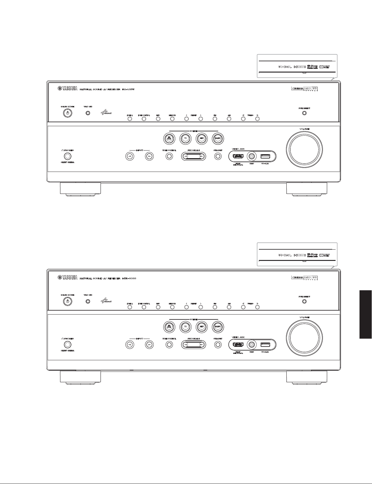
■ FRONT PANELS
RX-V675 (U, C, R, T, A, B, G, F, L, S, H models)
RX-V675/HTR-6066/RX-A730/TSR-6750
HTR-6066 (G, F models)
RX-V675/HTR-6066/
RX-A730/TSR-6750
3
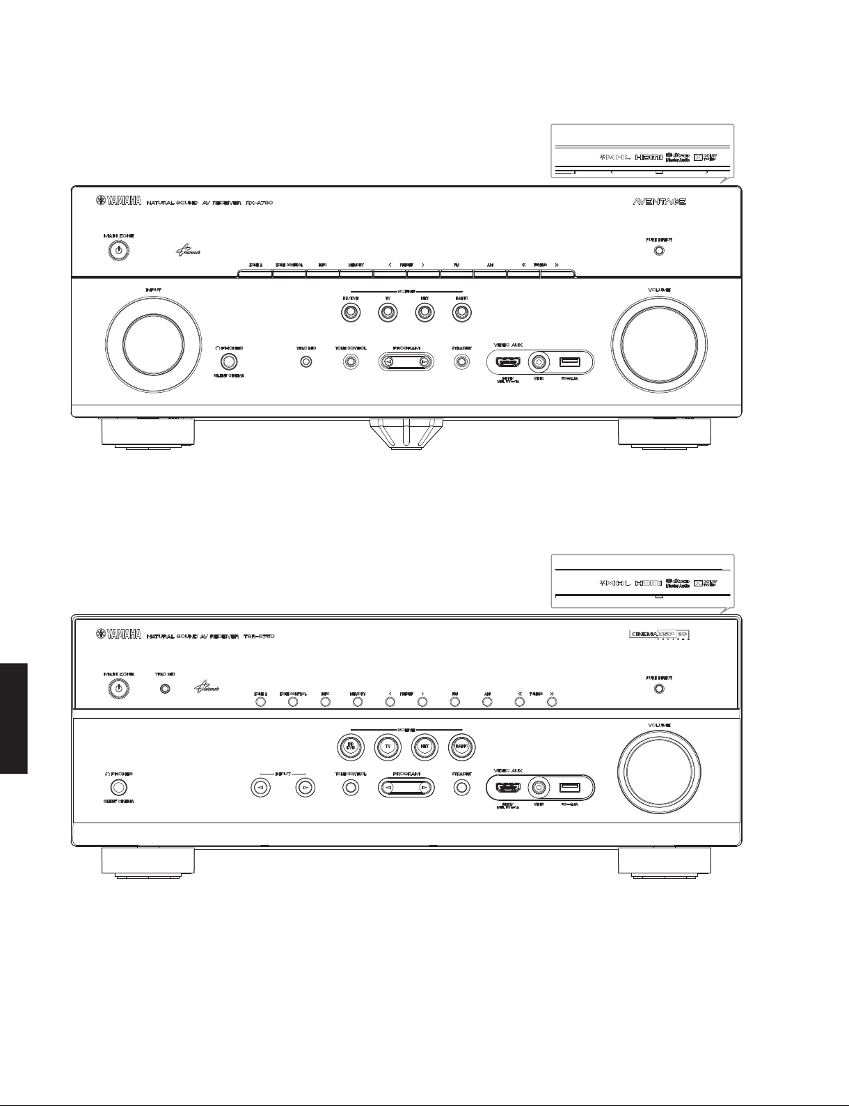
RX-V675/HTR-6066/RX-A730/TSR-6750
RX-A730 (U, C, A, B, G, L models)
TSR-6750 (U model)
RX-A730/TSR-6750
RX-V675/HTR-6066/
4
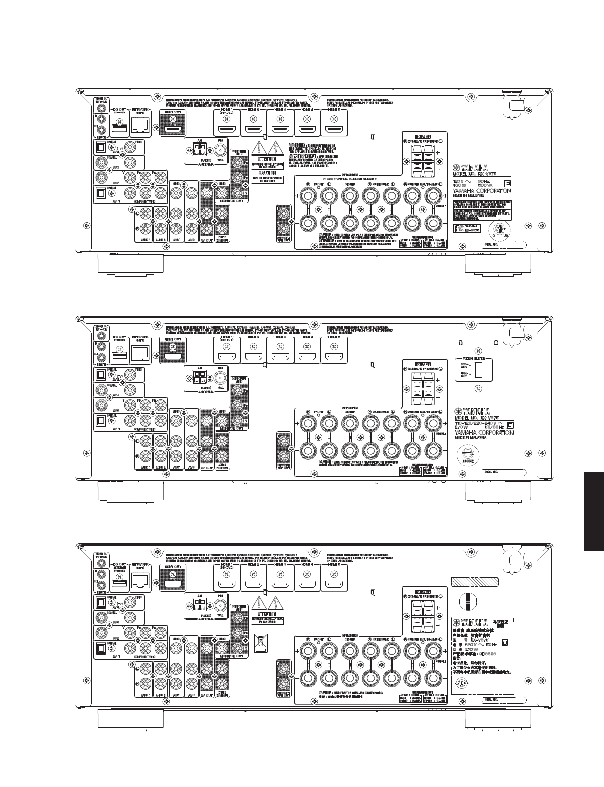
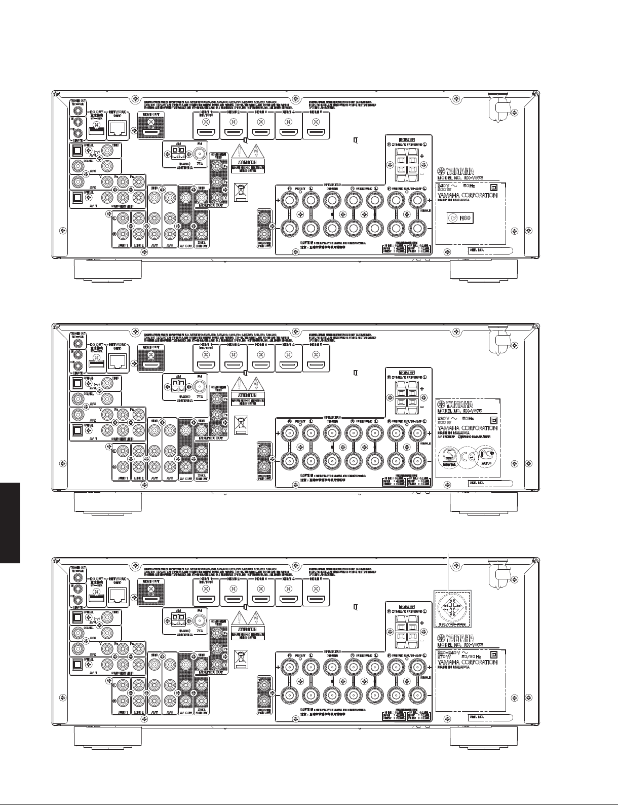
■ REAR PANELS
RX-V675 (U, C models)
RX-V675 (R, S models)
RX-V675/HTR-6066/RX-A730/TSR-6750
RX-V675 (T model)
RX-V675/HTR-6066/
RX-A730/TSR-6750
5
RX-V675/HTR-6066/RX-A730/TSR-6750
RX-V675 (A model)
RX-V675 (B, G, F models)
RX-A730/TSR-6750
RX-V675/HTR-6066/
RX-V675 (L, H models)
6
H model
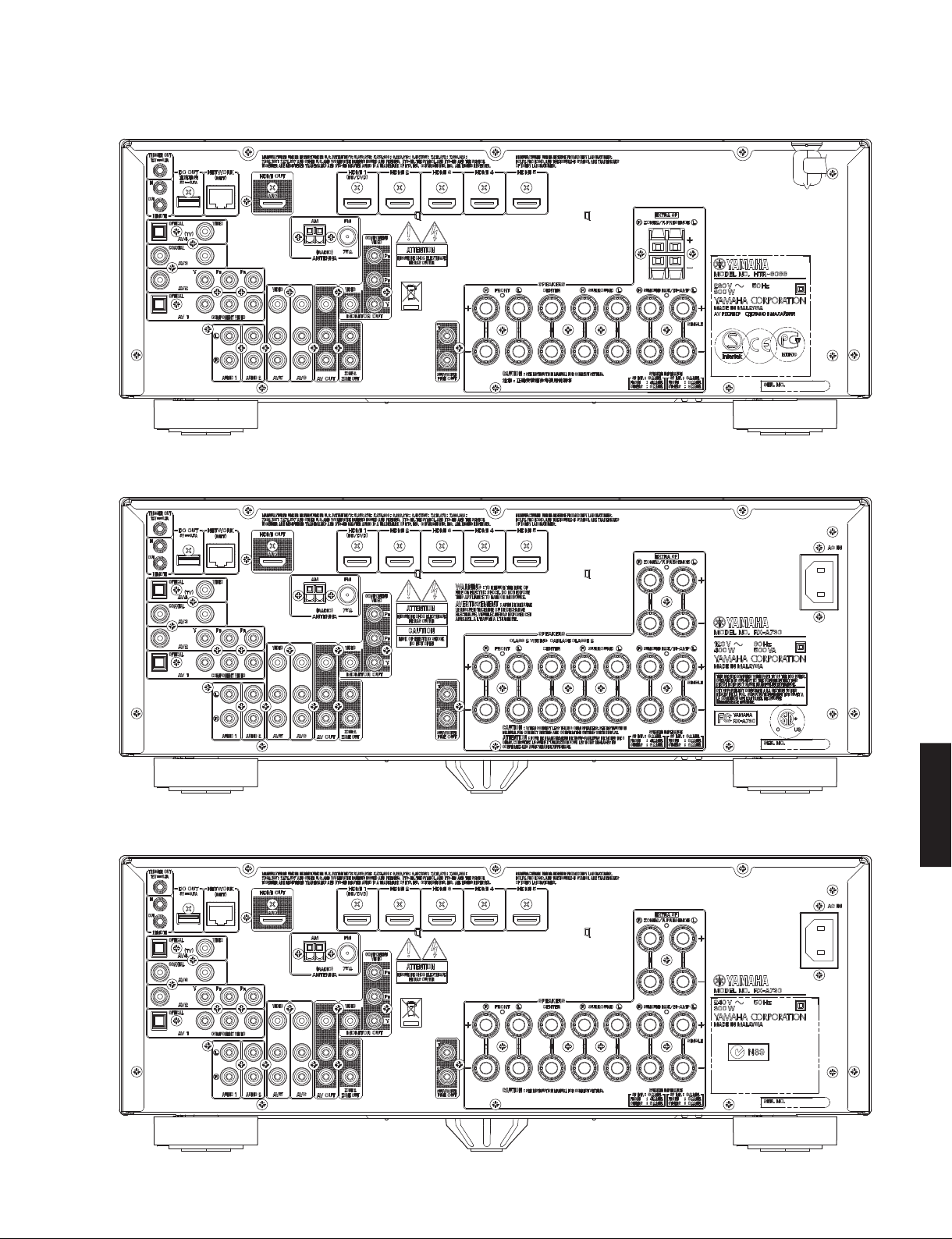
HTR-6066 (G, F models)
RX-A730 (U, C models)
RX-V675/HTR-6066/RX-A730/TSR-6750
RX-A730 (A model)
RX-V675/HTR-6066/
RX-A730/TSR-6750
7
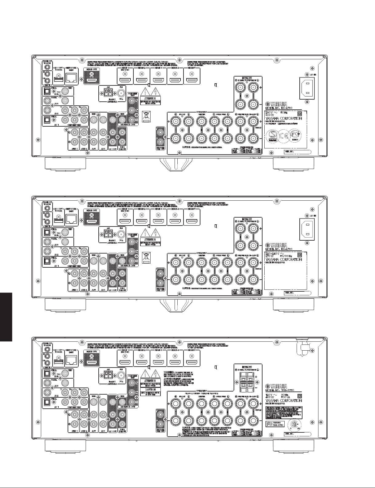
RX-V675/HTR-6066/RX-A730/TSR-6750
RX-A730 (B, G models)
RX-A730 (L model)
RX-A730/TSR-6750
RX-V675/HTR-6066/
TSR-6750 (U model)
8
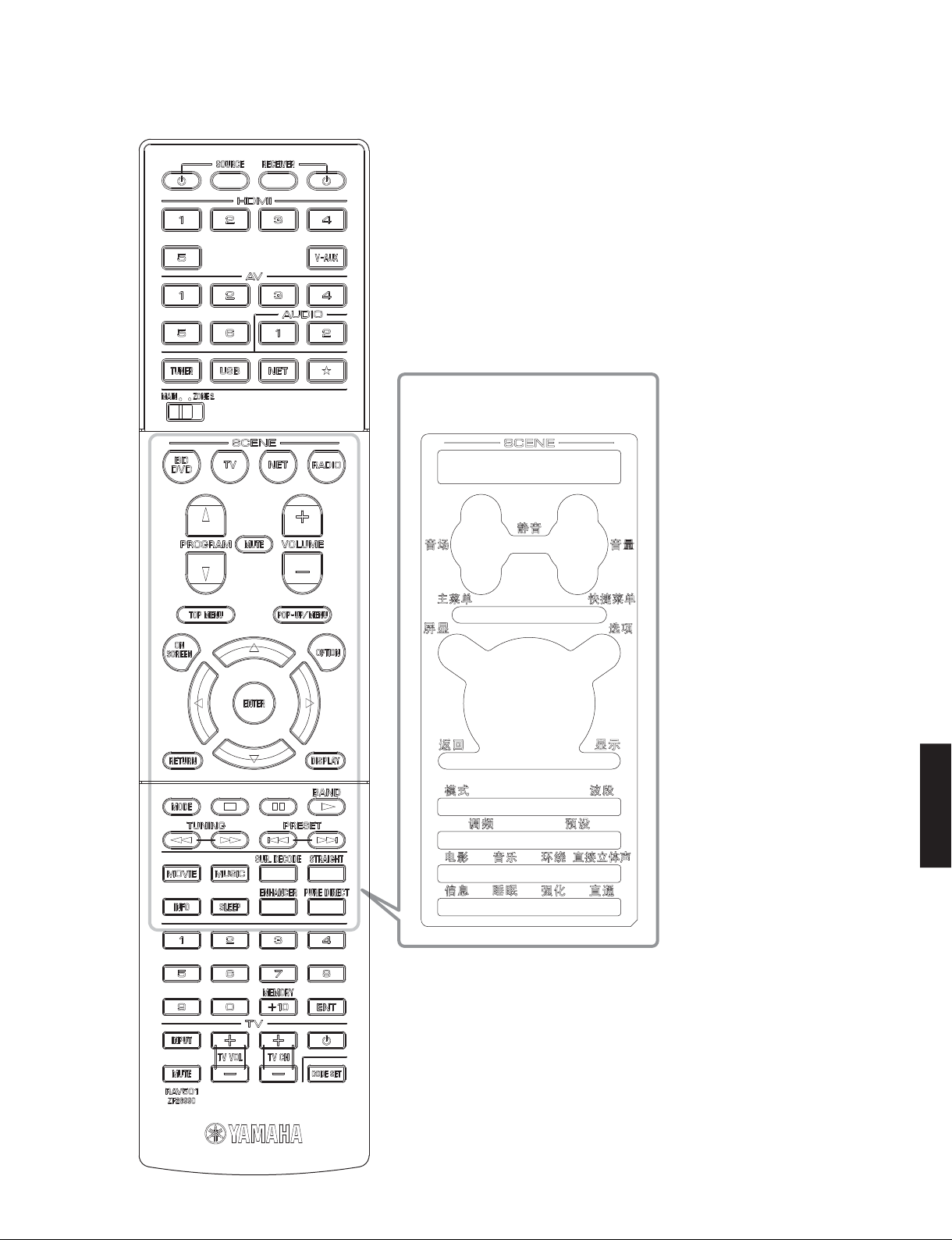
■ REMOTE CONTROL PANEL
RAV501
RX-V675/HTR-6066/RX-A730/TSR-6750
Remote control sheet
(T model)
RX-V675/HTR-6066/
RX-A730/TSR-6750
9

RX-V675/HTR-6066/RX-A730/TSR-6750
■ SPECIFICATIONS
■ Audio Section
Rated Output Power (Power Amp. Section)
(1 kHz, 0.9 % THD)
– 1 channel driven –
– 2 channels driven simultaneously –
(20 Hz to 20 kHz, 0.09 % THD)
– 2 channels driven simultaneously –
Maximum Effective Output Power (JEITA) [R, T, L, H models]
(1 channel driven, 1 kHz, 10 % THD, 8 ohms)
FRONT L/R ......................................................................... 150 W/ch
CENTER .................................................................................. 150 W
SURROUND L/R ................................................................150 W/ch
SURROUND BACK L/R .....................................................150 W/ch
Dynamic Power Per Channel (IHF)
FRONT L/R (1 channel driven)
(8 / 6 / 4 / 2 ohms) ..................................... 130 / 170 / 200 / 240 W
Damping Factor (20 Hz to 20 kHz, 8 ohms)
FRONT L/R to SPEAKER-A ............................................100 or more
Input Sensitivity/Input Impedance (1 kHz, 100 W/8 ohms)
AV5 etc. ............................................................200 mV / 47 k-ohms
Maximum Input Signal (1 kHz, 0.5 % THD)
AV5 etc. (EFFECT ON) .............................................................. 2.3 V
Output Level/Output Impedance
AV OUT ............................................................ 200 mV / 1.2 k-ohms
SUBWOOFER (2 ch stereo and FRONT SP: small)
RX-A730/TSR-6750
RX-V675/HTR-6066/
.............................................................................. 1 V / 1.2 k-ohms
ZONE2 OUT ..................................................... 200 mV / 1.2 k-ohms
Headphone Jack Rated Output/Output Impedance
(1 kHz, 50 mV, 8 ohms)
AV5 etc. input .....................................................100 mV / 560 ohms
Frequency Response (10 Hz to 100 kHz)
AV5 etc., FRONT ..................................................................0 / -3 dB
Total Harmonic Distortion (20 Hz to 20 kHz, 50 W/8 ohms)
AV5 etc. (PURE DIRECT) to FRONT SP OUT .............0.06 % or less
Signal to Noise Ratio (IHF-A Network) (Input shorted 250 mV)
AV5 etc. (PURE DIRECT) to SP OUT ....................... 100 dB or more
Residual Noise (IHF-A Network)
FRONT L/R to SP OUT ................................................150 V or less
Channel Separation (1 kHz / 10 kHz)
AV5 etc. (Input 5.1 k-ohms shorted)
...................................................... 60 dB or more / 45 dB or more
Volume Control/Step
......................................... MUTE / -80 dB to +16.5 dB / 0.5 dB step
U, C, R, T, A, B, G, F, L, S, H models (8 ohms)
FRONT L/R ................................................................ 125 W/ch
CENTER .......................................................................... 125 W
SURROUND L/R ........................................................ 125 W/ch
SURROUND BACK L/R .............................................125 W/ch
B, G, F models (4 ohms)
FRONT L/R ................................................................ 150 W/ch
U, C, R, T, A, B, G, F, L, S, H models (8 ohms)
FRONT L/R .......................................................105 W + 105 W
CENTER .......................................................................... 105 W
SURROUND L/R ...............................................105 W + 105 W
SURROUND BACK L/R ....................................105 W + 105 W
U, C, R, T, A, B, G, F, L, S, H models (8 ohms)
FRONT L/R ...........................................................90 W + 90 W
Tone Control Characteristics
Bass
Boost/Cut ........................................ ±6 dB / 0.5 dB step, at 50 Hz
Turnover frequency .............................................................350 Hz
Treble
Boost/Cut .......................................±6 dB / 0.5 dB step, at 20 kHz
Turnover frequency ............................................................ 3.5 kHz
Filter Characteristics
FRONT, CENTER, SURROUND, SURROUND BACK small (H.P.F.)
....................fc=40/60/80/90/100/110/120/160/200 Hz, 12 dB/oct.
SUBWOOFER small (L.P.F.)
....................fc=40/60/80/90/100/110/120/160/200 Hz, 24 dB/oct.
Optical Jack, Coaxial Jack Support Frequencies
............................................................................... 32 kHz to 96 kHz
■ Video Section
Video Signal Type
Monitor out (Wall paper)
U, C, R models ...................................................................... NTSC
T, A, B, G, F, L, S, H models ..................................................... PAL
Video conversion
.......................................................................................NTSC/PAL
Composite Video Signal Level
...............................................................................1 Vp-p / 75 ohms
Component Video Signal Level
Y .............................................................................1 Vp-p / 75 ohms
Pb/Pr ...................................................................0.7 Vp-p / 75 ohms
Video Maximum Input Level (VIDEO Conversion Off)
................................................................................ 1.5 Vp-p or more
Video Signal to Noise Ratio
................................................................................... 50 dB or more
Monitor Out Frequency Response (VIDEO Conversion Off)
Component video signal level .......................5 Hz to 60 MHz, -3 dB
■ FM Section
Tuning Range
U, C models ......................................................... 87.5 to 107.9 MHz
R, L, S, H models ..................... 87.5 to 108.0 / 87.50 to 108.00 MHz
T, A, B, G, F models ......................................... 87.50 to 108.00 MHz
50 dB Quieting Sensitivity (IHF) (1 kHz, 100 % MOD.)
Mono ......................................................................... 3 µV (20.8 dBf)
Signal to Noise Ratio (IHF)
Mono ........................................................................................71 dB
Stereo ......................................................................................69 dB
Harmonic Distortion (1 kHz)
Mono ........................................................................................ 0.3 %
Stereo ......................................................................................0.5 %
Antenna Input
......................................................................... 75 ohms unbalanced
10

■ AM Section
Tuning Range
U, C models ........................................................... 530 to 1,710 kHz
R, L, S, H models ............................ 530 to 1,710 / 531 to 1,611 kHz
T, A, B, G, F models ............................................... 531 to 1,611 kHz
Antenna
..................................................................................... Loop antenna
■ General
Power Supply
U, C models ............................................................ AC 120 V, 60 Hz
R, S models .................................AC 110–120/220–240 V, 50/60 Hz
T model ................................................................... AC 220 V, 50 Hz
A model .................................................................. AC 240 V, 50 Hz
B, G, F models ........................................................ AC 230 V, 50 Hz
L, H models ............................................... AC 220–240 V, 50/60 Hz
Power Consumption
U, C models ..............................................................400 W / 500 VA
R, T, L, S, H models ................................................................270 W
A, B, G, F models ...................................................................300 W
Standby Power Consumption (reference data)
HDMI control: OFF / Standby through: OFF
U, C models .............................................................0.10 W or less
R, T, A, B, G, F, L, S, H models ................................0.15 W or less
HDMI control: ON / Standby through: ON
INPUT: HDMI1(HDMI no signal)
................................................................................3.0 W or less
Network standby: ON
...................................................................................3.0 W or less
Maximum Power Consumption [R, L, S, H models]
................................................................................................ 590 W
Dimensions (W x H x D)
[RX-V675/HTR-6066/TSR-6750]
............................ 435 x 171 x 364 mm (17-1/8" x 6-3/4" x 14-3/8")
[RX-A730]
............................ 435 x 171 x 367 mm (17-1/8" x 6-3/4" x 14-1/2")
Weight
[RX-V675/HTR-6066/TSR-6750]
.............................................................................. 10.0 kg (22 lbs.)
[RX-A730]
........................................................................... 10.4 kg (22.9 lbs.)
Finish
[RX-V675]
T model ..........................................................................Gold color
U, C, R, T, A, B, G, F, L, S, H models ........................... Black color
U, A, B, G, F, L, H models ........................................Titanium color
[HTR-6066]
G, F models .................................................................. Black color
[RX-A730]
U, C, A, B, G, L models ................................................ Black color
B, G models .............................................................Titanium color
[TSR-6750]
U model ........................................................................ Black color
RX-V675/HTR-6066/RX-A730/TSR-6750
Accessories
Remote control ..............................................................................x 1
Batteries (R03, AAA, UM-4) ..........................................................x 2
FM antenna (1.4 m) ......................................................................x 1
AM antenna (1.0 m) ......................................................................x 1
YPAO microphone (6.0 m) ............................................................x 1
Remote control sheet (T model) ...................................................x 1
Antenna isolator (T model) ...........................................................x 1
Conversion plug (T model) ...........................................................x 1
Power cable (2.0 m) (RX-A730) ....................................................x 1
* Specifications are subject to change without notice.
U ........................U.S .A. model
C ..................Canadian model
R .....................General model
T..................... Chinese model
A .................Australian model
B .......................British model
Manufactured under license from Dolby Laboratories. Dolby, Pro Logic,
Surround EX and the double-D symbol are trademarks of Dolby Laboratories.
DTS-HD, the Symbol, & DTS-HD and the Symbol together are registered
trademarks & DTS-HD Master Audio is a trademark of DTS, Inc.
Product includes software. © DTS, Inc. All Rights Reserved.
AirPlay, the AirPlay logo, iPad, iPhone, iPod, iPod nano, and iPod touch are
trademarks of Apple Inc., registered in the U.S. and other countries.
MPEG Layer-3 audio coding technology licensed from Fraunhofer IIS and
Thomson.
This receiver supports network connections.
HDMI, the HDMI Logo, and High-Definition Multimedia Interface are
trademarks or registered trademarks of HDMI Licensing LLC in the United
States and other countries.
MHL and the MHL logo are a trademark, registered trademark or service
mark of MHL, LLC in the United States and/or other countries.
G ..................European model
F..................... Russian model
L..................Singapore model
S ...................Brazirian model
H ...........................Thai model
RX-V675/HTR-6066/
RX-A730/TSR-6750
11
RX-V675/HTR-6066/RX-A730/TSR-6750
“x.v.Color” is a trademark of Sony Corporation.
“SILENT CINEMA” is a trademark of Yamaha Corporation.
DLNA™ and DLNA CERTIFIED™ are trademarks or registered trademarks
of Digital Living Network Alliance. All rights reserved. Unauthorized use is
strictly prohibited.
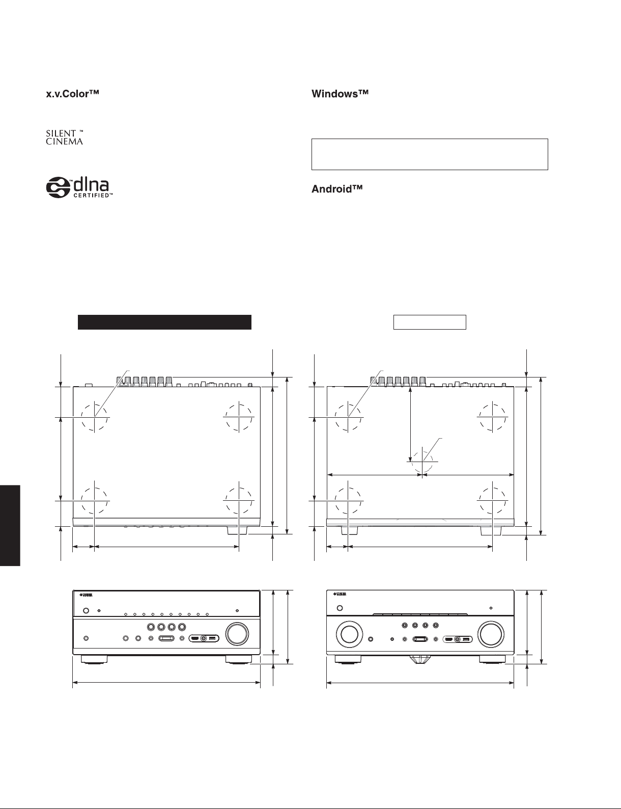
• DIMENSIONS
RX-V675/HTR-6066/TSR-6750 RX-A730
72
Top view
(2-7/8")
ø 60
22
Windows is a registered trademark of Microsoft Corporation in the United
States and other countries.
Internet Explorer, Windows Media Audio and Windows Media Player are
either registered trademarks or trademarks of Microsoft Corporation in the
United States and/or other countries.
Android is a trademark of Google Inc.
72
Top view
(2-7/8")
ø 60
(7/8")
22
(7/8")
193 (7-5/8")
59
RX-A730/TSR-6750
RX-V675/HTR-6066/
50
(2")
(2-1/4")
Front view
335 (13-1/4")
435 (17-1/8")
364 (14-3/8")
324 (12-3/4")
18
(3/4")
150 (5-7/8")
171 (6-3/4")
21
(7/8")
193 (7-5/8")
50
59
(2")
(2-1/4")
Front view
173 (6-3/4")
ø 48/18
222.5 (8-3/4") 212.5 (8-3/8")
335 (13-1/4")
435 (17-1/8")
Unit: mm (inch)Unit: mm (inch)
367 (14-1/2")
324 (12-3/4")
21
(7/8")
150 (5-7/8")
171 (6-3/4")
21
(7/8")
12
RX-V675/HTR-6066/RX-A730/TSR-6750
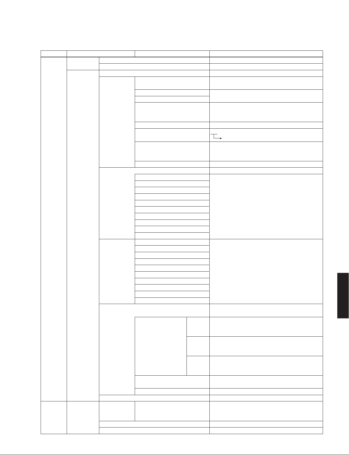
• SET MENU TABLE
MAIN MENU SUB-MENU PARAMETER VALUE [INITIAL VALUE]
Speaker Auto Measure Optimizes the speaker configuration automatically using YPAO.
Setup Result Not Available
Manual Power Amp Assign [Basic] / 7ch +1ZONE / 5ch BI-AMP
Configuration Front Large / [Small]
* “Front” is automatically set to “Large” when “Subwoofer” is set to “None”.
Center Large / [Small] / None
Surround
Surround Back Large x1 / Large x2 / Small x1 / [Small x2] / None
* This setting is not available when “Power Amp Assign” is set to “5ch BI-
AMP”, or when “Surround” is set to “None”.
Front Presence [Use] / None
Subwoofer Use / None
[Normal] / Reverse
Extra Bass [Off] / On
* This setting is not available when “Subwoofer” is set to “None”, or when
“Front” is set to “Small”.
Bass Cross Over 40 / 60 / [80] / 90 / 100 / 110 / 120 / 160 / 200 Hz
Distance Meter / Feet
Front L
Front R
Center
Surround L
Surround R 0.30 to 24.00 m, [3.00 m], 0.05 m step
Surround Back L 1.0 to 80.0 ft, [10.0 ft], 0.2 ft step
Surround Back R
Front Presence L
Front Presence R
Subwoofer
Level Front L
Front R
Center
Surround L
Surround R -10.0 to +10.0 dB, [0.0 dB], 0.5 dB step
Surround Back L
Surround Back R
Front Presence L
Front Presence R
Subwoofer
Parametric EQ Manual / YPAO : Flat / YPAO : Front / YPAO : Natural / Through
* Select “ENTER”
Front L Band
Front R / Gain▲ Gain: -20.0 to +6.0 dB, [0.0 dB], 0.5 dB step
Center
Surround L Frequency▶ Frequency: 31.3 Hz to 16.0 kHz, [62.5 Hz]
Surround R / Gain▲ Gain: -20.0 to +6.0 dB, [0.0 dB], 0.5 dB step
Surround Back L
Surround Back R Q
Front Presence L / Gain▲ Gain: -20.0 to +6.0 dB, [0.0 dB], 0.5 dB step
Front Presence R
PEQ Data Copy Flat > Manual / Front > Manual / Natural > Manual
PEQ Data Clear OK / CANCEL
Test Tone [Off] / On
Sound Setup Lipsync Delay Enable HDMI1 / HDMI2 / HDMI3 / HDMI4 /
HDMI5 / AV1 / AV2 / AV3 / AV4 / AV5 / Disable / [Enable]
AV6 / V-AUX / AUDIO1 / AUDIO2
Auto/Manual Select [Auto] / Manual
Adjustment 0 to 500 ms, [0 ms], 1 ms step
Band: #1 to #7
▶
Q: 0.500 to 10.080, [1.000]
▶
* Select “ENTER”
* Select “ENTER”
RX-V675/HTR-6066/
RX-A730/TSR-6750
13
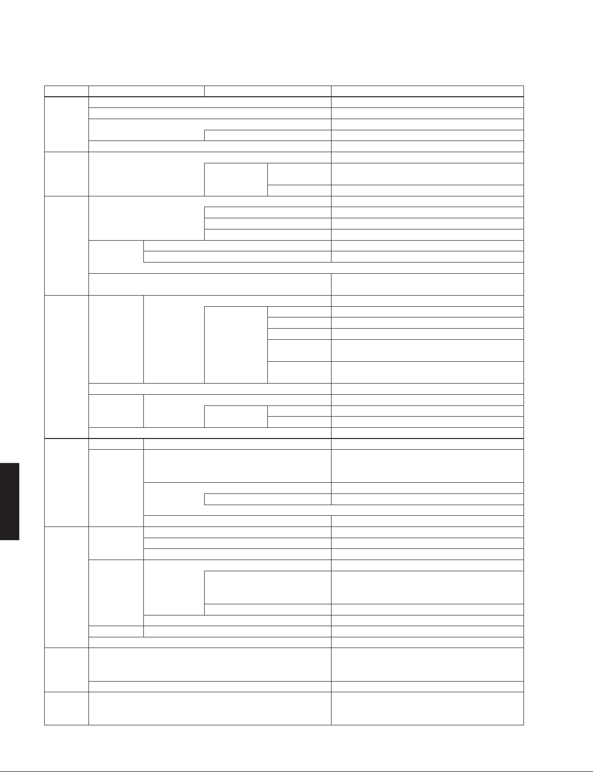
RX-V675/HTR-6066/RX-A730/TSR-6750
MAIN MENU SUB-MENU PARAMETER VALUE [INITIAL VALUE]
Sound Setup Dynamic Range [Maximum] / Standard / Minimum/Auto
Video Setup Video Mode [Direct] / Processing
HDMI Setup HDMI Control [Off] / On
Network IP Address DHCP Off / [On]
Setup Select “Off” IP Address xxx.xxx.xxx. x
Multi Zone Main Zone Set Zone Rename Input is possible to 9 characters
Setup Zone2 Set Max. Volume -30.0 to +15.0 dB, 5.0 dB step / [+16.5 dB (Maximum volume)]
RX-A730/TSR-6750
RX-V675/HTR-6066/
Function Display Set Dimmer (Front Display) -4 to 0 (higher to brighten), [0], 1 step
Setup Short Message [On] / Off
ECO Setup Auto Power Standby Off / 2 Hours / 4 Hours / 8 Hours / 12 Hours
Language [English (English)] /
Setup Deutsch (German) / Español (Spanish) / Русский (Russian) /
Max. Volume -30.0 to +15.0 dB, 5.0 dB step / [+16.5 dB (Maximum volume)]
Initial Volume [Off] / On
Select “On” Mute, -80.0 to +16.5 dB, [-40.0 dB], 0.5 dB step
Adaptive DSP Level Off / [On]
Select Resolution Through / [Auto] / 480p/576p / 720p / 1080i / 1080p / 4K
“Processing”
* Select “ENTER”
Aspect [Through] / 16:9 Normal
TV Audio Input AV1 / AV2 / AV3 / [AV4] / AV5 / AV6 / AUDIO1 / AUDIO2
ARC (Audio Return Channel) Off / [On]
Standby Sync Off / On / [Auto]
Audio Output Amp Off / [On]
HDMI OUT (TV) [Off] / On
* This setting is available only when “HDMI Control” is set to “Off”.
Standby Through [Off] / On
* This setting is available only when “HDMI Control” is set to “Off”.
Subnet Mask xxx.xxx.xxx. x
Default Gateway xxx.xxx.xxx. x
DNS Server (P) x. x. x. x
Primary
DNS Server (S) x. x. x. x
Secondary
Network Standby [Off] / On
MAC Address Filter [Off] / On
Filter Select “On” MAC Address 1–5 xx : xx : xx : xx : xx : xx
MAC Address 6–10 xx : xx : xx : xx : xx : xx
Network Name Input is possible to 15 characters
* This setting is available only when “Power Amp Assign” is set to “7ch
+1ZONE”.
Initial Volume [Off] / On
Select “On” Mute, -80.0 to +16.5 dB, [-40.0 dB], 0.5 dB step
* This setting is available only when “Power Amp Assign” is set to “7ch +1ZONE”.
Zone Rename Input is possible to 9 characters
Wall Paper [Picture1] / Picture2 / Picture3 / Gray
Trigger Output Trigger Mode [Power] / Source / Manual
Select “Source” HDMI1–5, AV1–6, V-AUX, AUDIO1–2, TUNER, Rhapsody,
Pandora, AirPlay, SERVER, NET RADIO, USB
Low / [High]
Select “Manual” Low / [High]
Target Zone Main / Zone2 / [All]
DC OUT Power Mode [Continuous] / Main Zone Power Sync.
Memory Guard [Off] / On
U, C, R, T, K, A, L, S, H models: [Off]
B, G, F models: [8 Hours]
ECO Mode [Off] / On
(Japanese) / Français (French) /
日本語
Italiano (Italian) / 中文 (Chinese)
14
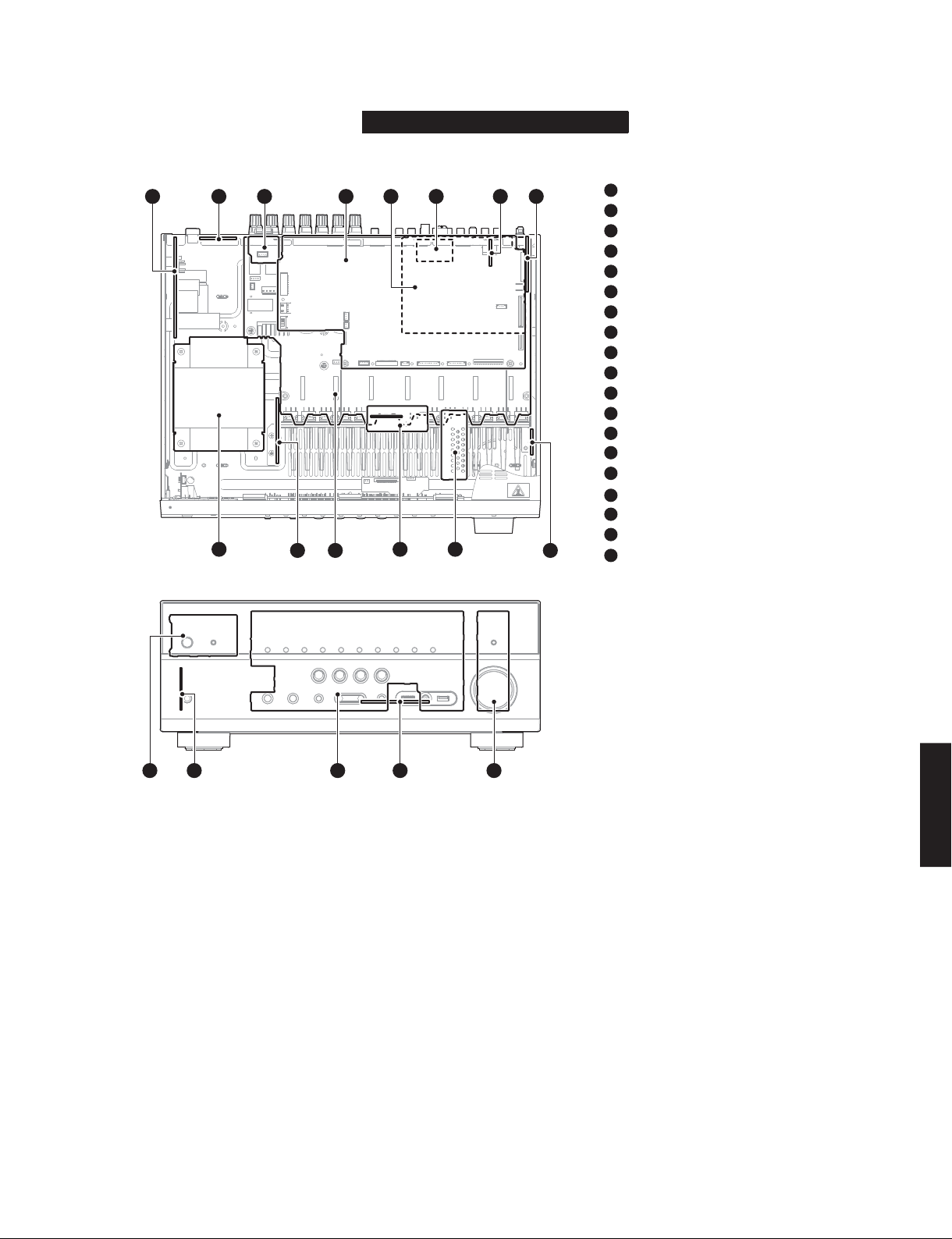
■ INTERNAL VIEW
RX-V675/HTR-6066/TSR-6750
Top view
158723 4 6
14
Front view
12
RX-V675/HTR-6066/RX-A730/TSR-6750
1
OPERATION (3) P.C.B.
2
MAIN (2) P.C.B. (R, S models)
3
OPERATION (8) P.C.B.
4
DIGITAL (1) P.C.B.
5
OPERATION (2) P.C.B.
6
AM/FM TUNER
7
OPERATION (9) P.C.B.
8
OPERATION (4) P.C.B.
9
MAIN (6) P.C.B.
10
MAIN (4) P.C.B.
11
MAIN (3) P.C.B.
12
MAIN (1) P.C.B.
13
MAIN (5) P.C.B.
14
POWER TRANSFORMER
15
OPERATION (6) P.C.B.
16
OPERATION (7) P.C.B.
17
OPERATION (1) P.C.B.
18
1011
913
DIGITAL (2) P.C.B.
19
OPERATION (5) P.C.B.
15 16 17 18 19
RX-V675/HTR-6066/
RX-A730/TSR-6750
15
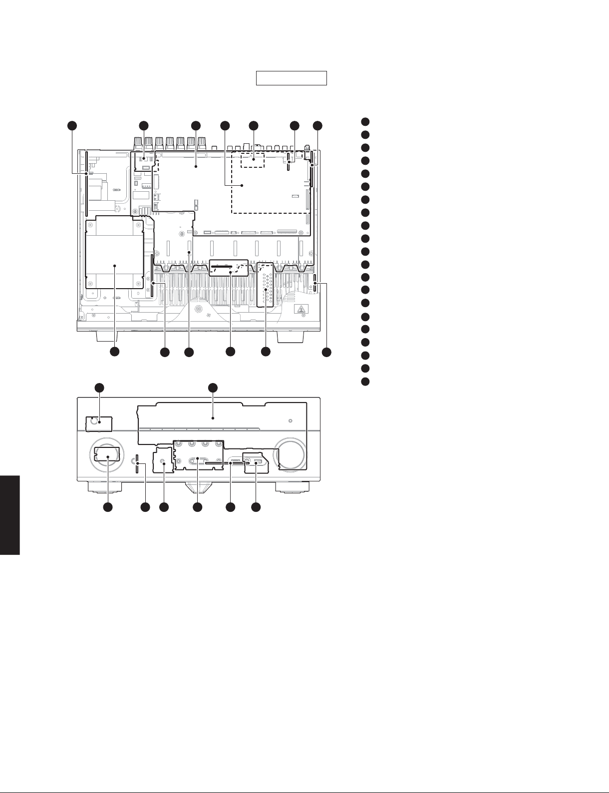
RX-V675/HTR-6066/RX-A730/TSR-6750
Top view
147623
13
11
Front view
RX-A730
1
5
910
1514
812
OPERATION (3) P.C.B.
2
OPERATION (8) P.C.B.
3
DIGITAL (1) P.C.B.
4
OPERATION (2) P.C.B.
5
AM/FM TUNER
6
OPERATION (9) P.C.B.
7
OPERATION (4) P.C.B.
8
MAIN (6) P.C.B.
9
MAIN (4) P.C.B.
10
MAIN (3) P.C.B.
11
MAIN (1) P.C.B.
12
MAIN (5) P.C.B.
13
POWER TRANSFORMER
14
OPERATION (5) P.C.B.
15
OPERATION (1) P.C.B.
16
OPERATION (12) P.C.B.
17
DIGITAL (2) P.C.B.
18
OPERATION (11) P.C.B.
19
OPERATION (6) P.C.B.
20
OPERATION (7) P.C.B.
21
OPERATION (10) P.C.B.
RX-A730/TSR-6750
RX-V675/HTR-6066/
■ SERVICE PRECAUTIONS
Safety measures
• Some internal parts in this product contain high voltages and are dangerous.
Be sure to take safety measures during servicing, such as wearing insulating gloves.
• Note that the capacitors indicated below are dangerous even after the power is turned off because an electric charge
remains and a high voltage continues to exist there.
Before starting any repair work, connect a discharging resistor (5 k-ohms/10 W) to the terminals of each capacitor
indicated below to discharge electricity.
The time required for discharging is about 30 seconds per each.
For details, refer to “PRINTED CIRCUIT BOARDS”.
16
20 181921 17 16
C1084 and C1085 on MAIN (1) P.C.B.
C3706 on OPERATION (3) P.C.B.
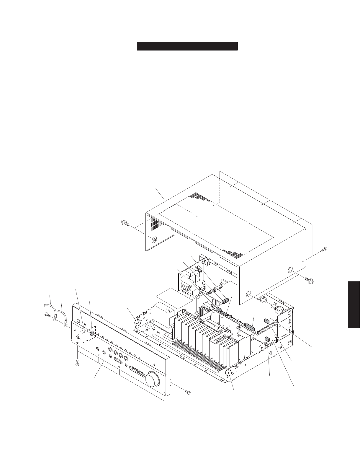
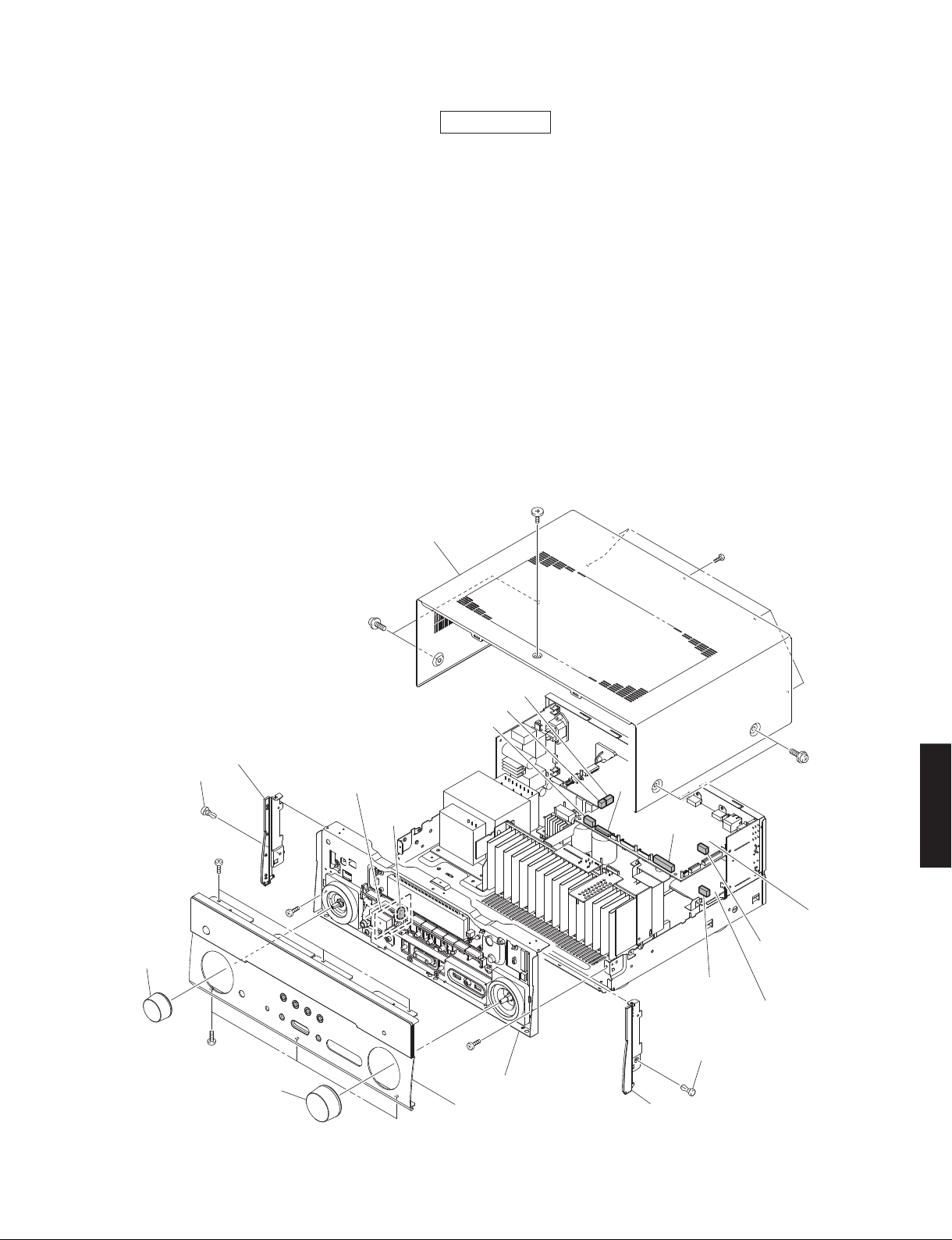
■ DISASSEMBLY PROCEDURES
RX-V675/HTR-6066/TSR-6750
(Remove parts in the order as numbered.)
Disconnect the power cable from the AC outlet.
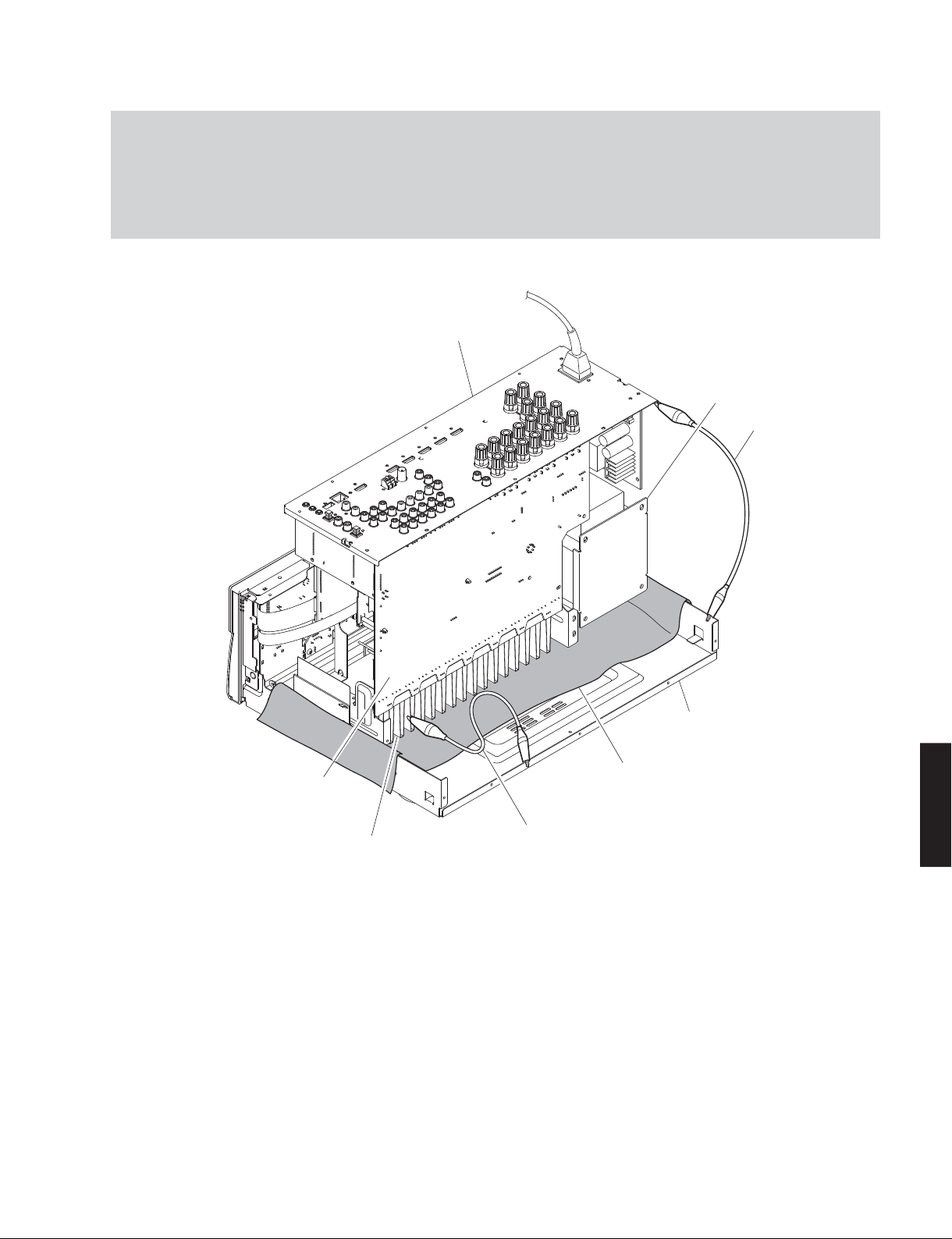
1. Removal of Top Cover
a. Remove 4 screws (①) and 5 screws (②). (Fig. 1)
b. Lift the rear of the top cover to remove it. (Fig. 1)
2. Removal of Front Panel Unit
a. Remove 6 screws (③), and remove W3001 and W3007. (Fig. 1)
b. Remove CB8, CB82, CB308, CB343, CB411, CB412, CB947 and CB952. (Fig. 1)
c. Release 2 hooks, and remove the front panel unit. (Fig. 1)
Top cover
RX-V675/HTR-6066/RX-A730/TSR-6750
OPERATION (7) P.C.B.
W3007
W3001
③
CB308
③
Front panel unit
①
Hook
CB411
CB947
CB412
③
CB8
Hook
CB82
CB952
CB343
OPERATION (2) P.C.B.
②
①
DIGITAL (1) P.C.B.
RX-V675/HTR-6066/
RX-A730/TSR-6750
Fig. 1
17
RX-V675/HTR-6066/RX-A730/TSR-6750
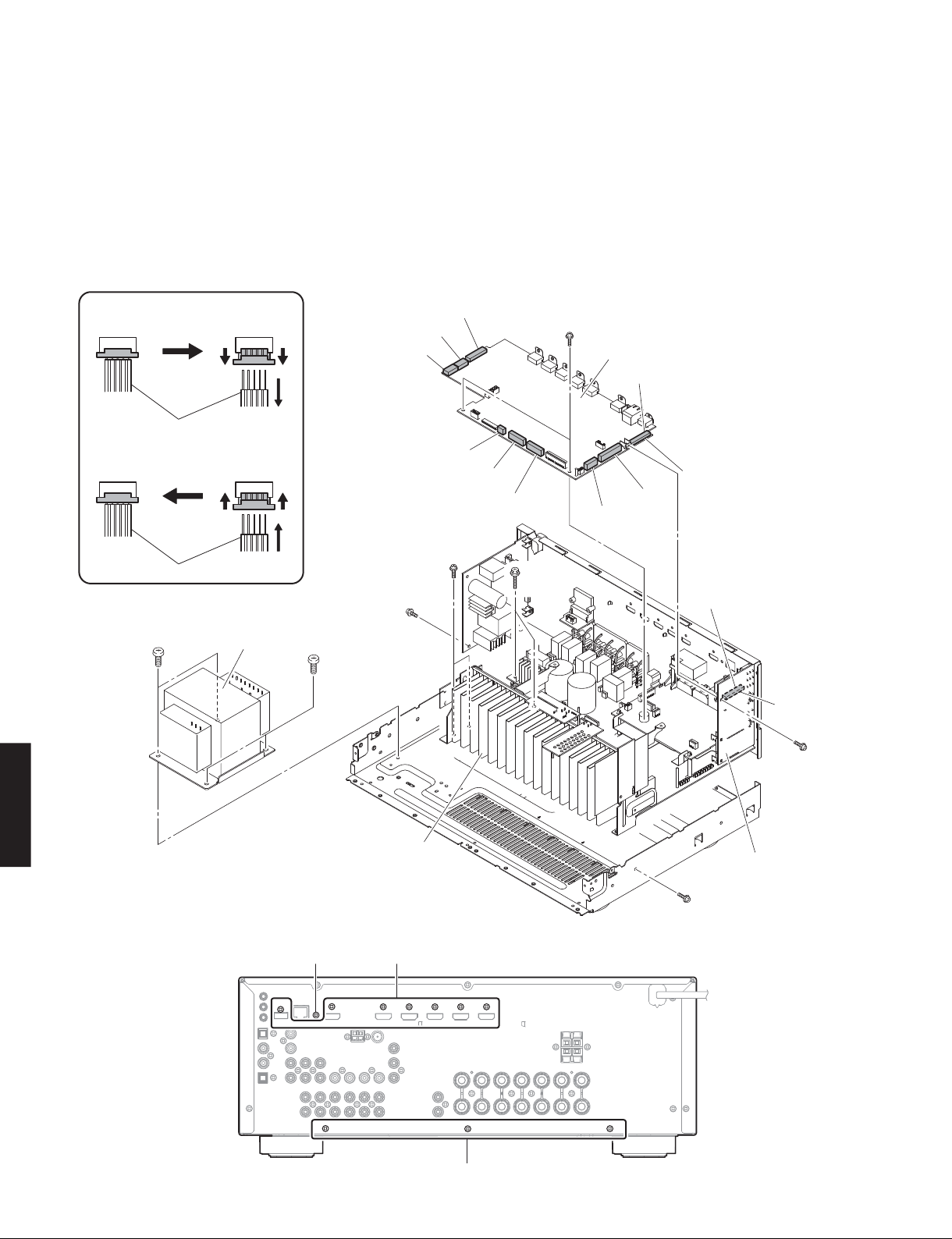
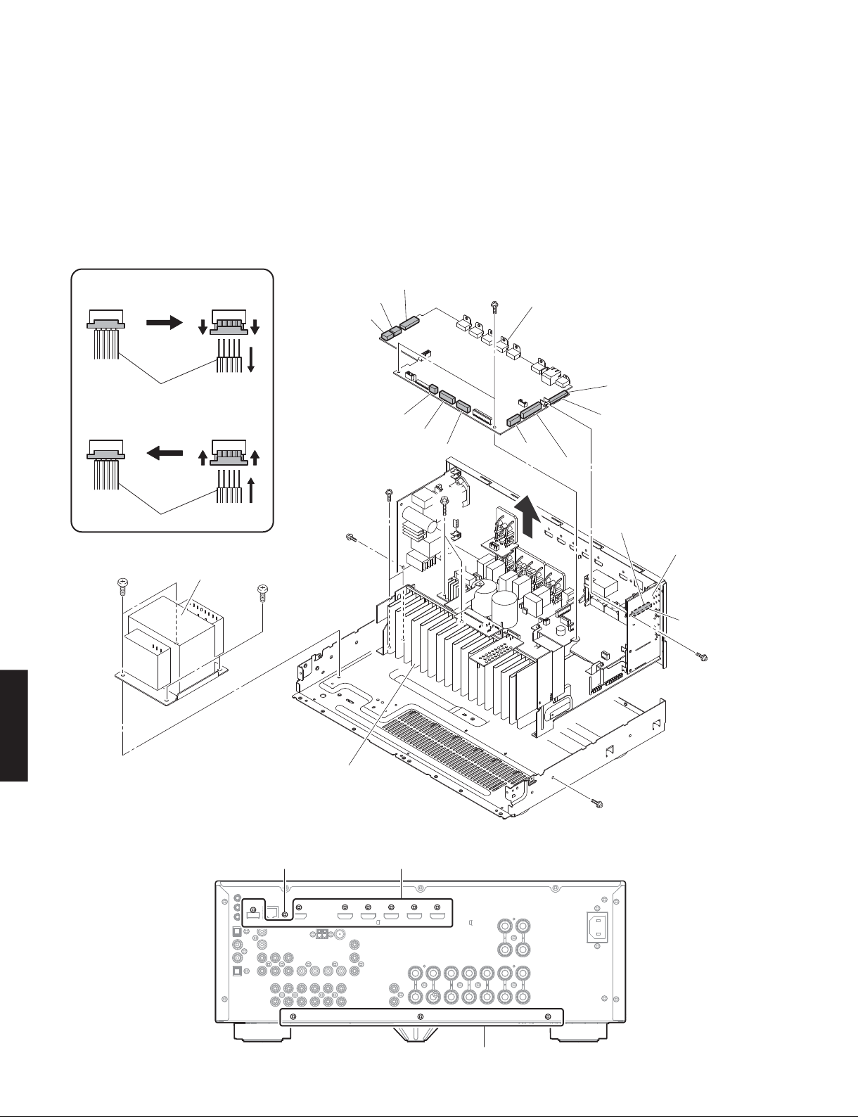
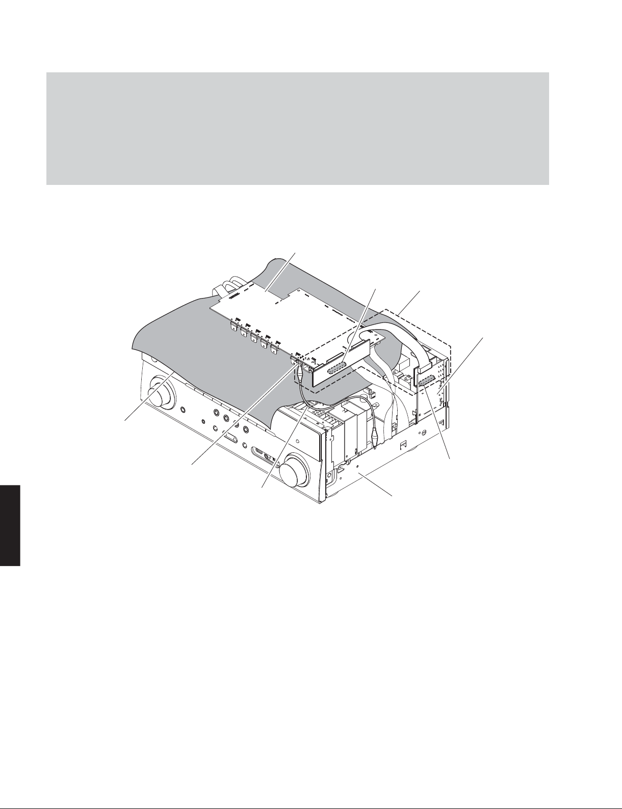
3. Removal of DIGITAL (1) P.C.B.
a. Remove screw (④) and 7 screws (⑤). (Fig. 3)
b. Remove 3 screws. (⑥). (Fig. 2)
c. Remove CB76, CB78, CB79, CB80, CB942 and CB944.
(Fig. 2)
d. Unlock and remove CB946 and CB948. (Fig. 2)
e. Remove the DIGITAL (1) P.C.B. which is connected
directly to the OPERATION (4) P.C.B. with board-to-
board connectors. (Fig. 2)
Remove CB946 and CB948
Connected
Cable
Connect CB946 and CB948
Connected
Cable
Unlock the connector
①
Remove the cable
②
①①
②
Lock the connector
①
Insert the cable
②
①①
②
CB942
CB944
4. Removal of AMP Unit and Power Transformer
a. Remove screw (⑦), 2 screws (⑧), 3 screws (⑨) and
4 screws (⑩). (Fig. 2)
b. Remove 3 screws (⑪). (Fig. 3)
c. Remove the AMP unit together with the power
transformer. (Fig. 2)
CB76
CB79
CB78
CB80
⑨
⑥
DIGITAL (1) P.C.B.
CB945
Board-to-board connectors
CB946
CB948
⑧
RX-A730/TSR-6750
RX-V675/HTR-6066/
⑩
Power transformer
⑩
⑦
AMP unit
⑤④
Board-to-board connectors
CB381
⑥
OPERATION (4) P.C.B.
⑨
Fig. 2
Rear view
18
⑪
Fig. 3
RX-V675/HTR-6066/RX-A730/TSR-6750
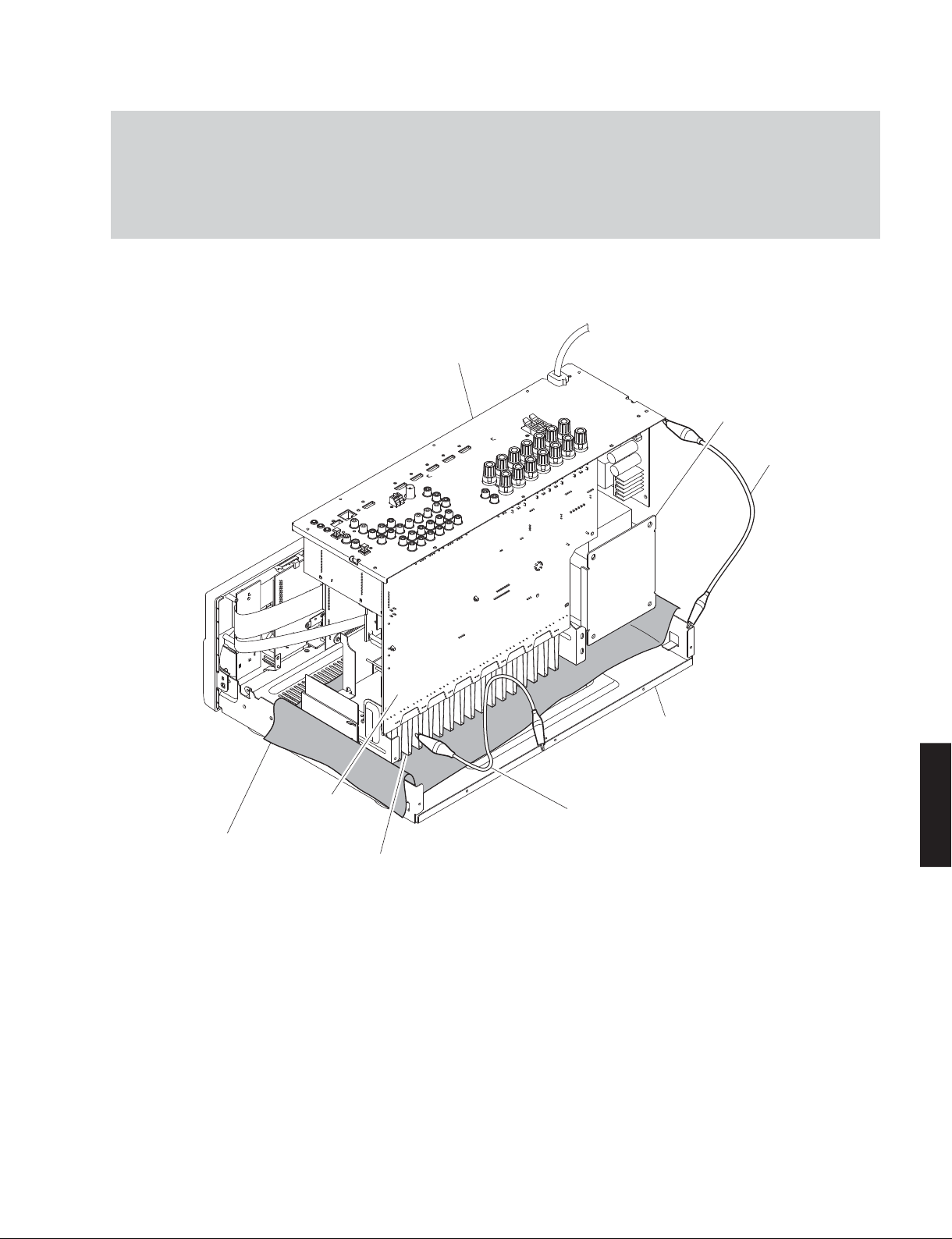
When checking the MAIN (1) P.C.B.:
• Place the P.C.B.s (with rear panel) upright. (Fig. 4)
• Connect the heatsink and rear panel to the chassis with a ground lead or the like. (Fig. 4)
• Reconnect all cables (connectors) that have been disconnected.
• When connecting the flexible flat cable, be careful with polarity.
Rear panel
Power transformer
Ground lead
Rubber sheet and cloth
MAIN (1) P.C.B.
Heatsink
Fig. 4
Ground lead
Chassis
RX-V675/HTR-6066/
RX-A730/TSR-6750
19
RX-V675/HTR-6066/RX-A730/TSR-6750
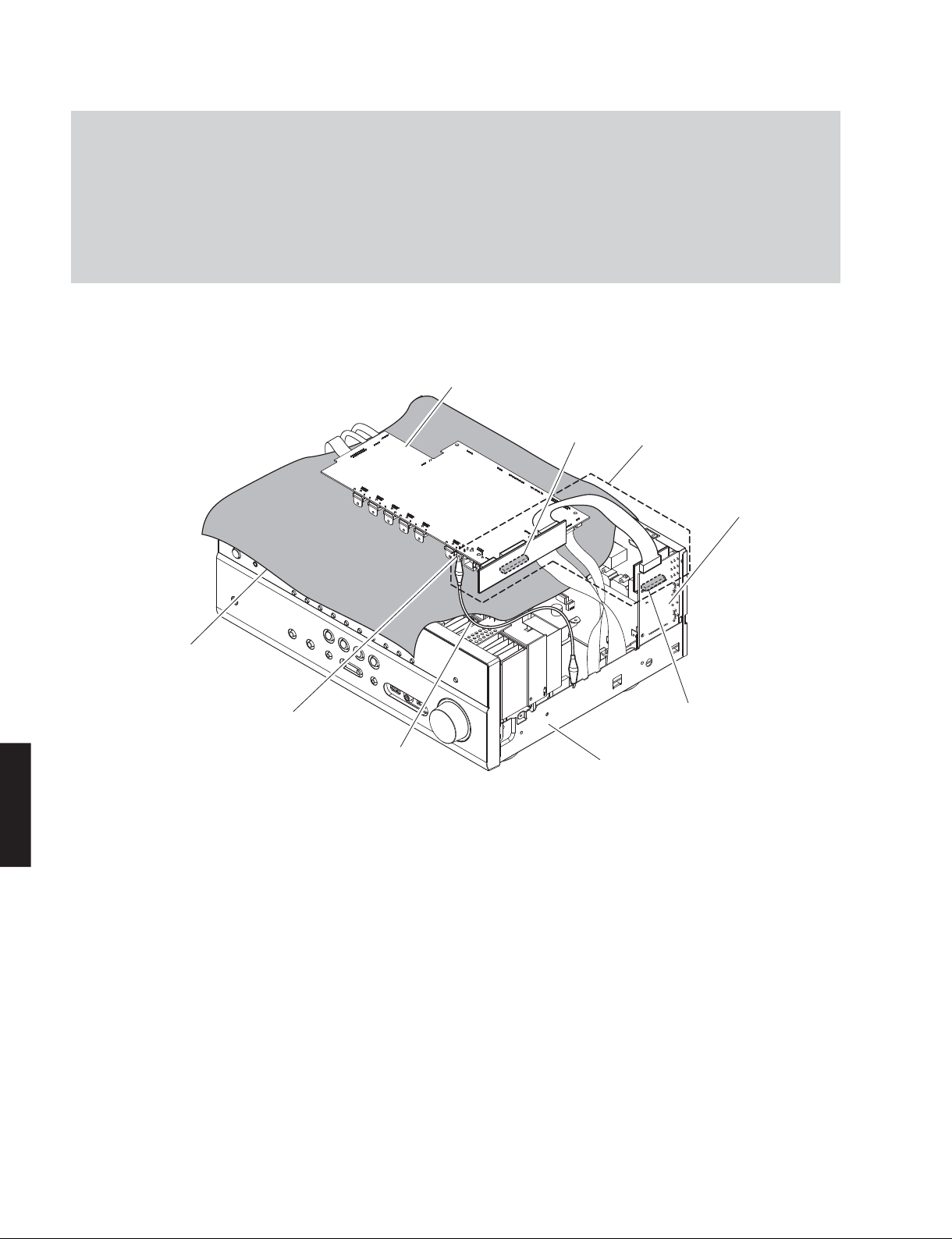
When checking the DIGITAL (1) P.C.B.:
• Put the rubber sheet and cloth over this unit, and place the DIGITAL (1) P.C.B. on them. (Fig. 5)
• Connect ST951 on DIGITAL (1) P.C.B. to the chassis with a ground lead. (Fig. 5)
• Reconnect all cables (connectors) that have been disconnected. Be sure to use the P.C.B. CHECKING JIG (Part No.
ZF454800) to connect between the following connectors.
CB945 on DIGITAL (1) P.C.B. – CB381 on OPERATION (4) P.C.B.
• When connecting the flexible flat cable, be careful with polarity.
DIGITAL (1) P.C.B.
RX-A730/TSR-6750
RX-V675/HTR-6066/
Rubber sheet and cloth
ST951
Ground lead
Fig. 5
CB945
P.C.B. CHECKING JIG
OPERATION (4) P.C.B.
CB381
Chassis
20
RX-V675/HTR-6066/RX-A730/TSR-6750
RX-A730
(Remove parts in the order as numbered.)
Disconnect the power cable from the AC outlet.
1. Removal of Top Cover
a. Remove 4 screws (①), 5 screws (②) and screw (③). (Fig. 1)
b. Lift the rear of the top cover to remove it. (Fig. 1)
2. Removal of Front Panel Unit and Sub-Chassis Unit
a. Remove knob (INPUT) and knob (VOLUME). (Fig. 1)
b. Remove 6 screws (④) and then remove the front panel unit. (Fig. 1)
c. Remove 2 push rivets and then remove the side plate (L) and side plate (R). (Fig. 1)
d. Remove CB8, CB82, CB302, CB343, CB411, CB412, CB947 and CB952. (Fig. 1)
e. Remove 2 screws (⑤) and then remove the sub-chassis unit. (Fig. 1)
Knob
(INPUT)
Side plate (L)
Push rivet
④
OPERATION (7) P.C.B.
⑤
①
CB302
Top cover
CB411
CB947
CB412
③
CB8
CB82
②
DIGITAL (1) P.C.B.
CB952
CB343
OPERATION (2) P.C.B.
①
RX-V675/HTR-6066/
RX-A730/TSR-6750
④⑤
Knob
(VOLUME)
Sub-chassis unit
Front panel unit
Push rivet
Side plate (R)
Fig. 1
21
RX-V675/HTR-6066/RX-A730/TSR-6750
3. Removal of DIGITAL (1) P.C.B.
a. Remove screw (⑥) and 7 screws (⑦). (Fig. 3)
b. Remove 3 screws. (⑧). (Fig. 2)
c. Remove CB76, CB78, CB79, CB80, CB942 and CB944.
(Fig. 2)
d. Unlock and remove CB946 and CB948. (Fig. 2)
e. Remove the DIGITAL (1) P.C.B. which is connected
directly to the OPERATION (4) P.C.B. with board-to-
board connectors. (Fig. 2)
Remove CB946 and CB948
Connected
Cable
Connect CB946 and CB948
Connected
Cable
⑫
Unlock the connector
①
Remove the cable
②
①①
Lock the connector
①
Insert the cable
②
①①
Power transformer
CB942
CB944
②
CB79
⑪
②
⑨
⑫
4. Removal of AMP Unit and Power Transformer
a. Remove screw (⑨), 2 screws (⑩), 3 screws (⑪) and
4 screws (⑫). (Fig. 2)
b. Remove 3 screws (⑬). (Fig. 3)
c. Remove the AMP unit together with the power
transformer. (Fig. 2)
CB76
CB78
CB80
⑧
DIGITAL (1) P.C.B.
CB945
Board-to-board connectors
CB948
CB946
⑩
Board-to-board connectors
OPERATION (4) P.C.B.
RX-A730/TSR-6750
RX-V675/HTR-6066/
AMP unit
Fig. 2
⑥⑦
CB381
⑧
⑪
Rear view
22
⑬
Fig. 3
RX-V675/HTR-6066/RX-A730/TSR-6750
When checking the MAIN (1) P.C.B.:
• Place the P.C.B.s (with rear panel) upright. (Fig. 4)
• Connect the heatsink and rear panel to the chassis with a ground lead or the like. (Fig. 4)
• Reconnect all cables (connectors) that have been disconnected.
• When connecting the flexible flat cable, be careful with polarity.
Rear panel
Power transformer
Ground lead
MAIN (1) P.C.B.
Heatsink
Ground lead
Fig. 4
Chassis
Rubber sheet and cloth
RX-V675/HTR-6066/
RX-A730/TSR-6750
23
RX-V675/HTR-6066/RX-A730/TSR-6750
When checking the DIGITAL (1) P.C.B.:
• Put the rubber sheet and cloth over this unit, and place the DIGITAL (1) P.C.B. on them. (Fig. 5)
• Connect ST951 on DIGITAL (1) P.C.B. to the chassis with a ground lead. (Fig. 5)
• Reconnect all cables (connectors) that have been disconnected. Be sure to use the P.C.B. CHECKING JIG (Part No.
ZF454800) to connect between the following connectors.
CB945 on DIGITAL (1) P.C.B. – CB381 on OPERATION (4) P.C.B.
• When connecting the flexible flat cable, be careful with polarity.
DIGITAL (1) P.C.B.
RX-A730/TSR-6750
RX-V675/HTR-6066/
Rubber sheet and cloth
ST951
Ground lead
Fig. 5
CB945
P.C.B. CHECKING JIG
OPERATION (4) P.C.B.
CB381
Chassis
24

RX-V675/HTR-6066/RX-A730/TSR-6750
■ UPDATING FIRMWARE
When the following parts are replaced, the firmware must be updated to the latest version.
DIGITAL P.C.B.
FPGA Flash ROM: IC77 on DIGITAL (1) P.C.B.
DSP (TI) Flash ROM: IC923 on DIGITAL (1) P.C.B.
NETWORK Flash ROM: IC953 on DIGITAL (1) P.C.B.
● Confirmation of firmware version and checksum
Before and after updating the firmware, check the firmware version and checksum by using the self-diagnostic
function menu.
Start up the self-diagnostic function and select “S4. ROM VERSION/CHECKSUM” menu.
Using the sub-menu, have the firmware version and checksum displayed, and note them down.
(For details, refer to “SELF-DIAGNOSTIC FUNCTION”)
* When the firmware version is different from written one after updating, perform the updating procedure again from
the beginning again.
● Initializing the back-up IC (EEPROM: IC82 on DIGITAL P.C.B.)
After updating the firmware, the back-up IC MUST be initialized by the following procedure to store the setting
information (soundfield parameters, system memory and tuner presetting, etc.) properly.
Start up the self-diagnostic function and select “S3. FACTORY PRESET” menu.
(For details, refer to “SELF-DIAGNOSTIC FUNCTION”)
Select “PRESET RSRV”, press the “MAIN ZONE
the back-up IC is initialized.
” key to turn off the power once and turn on the power again. Then
● Required Tools
• USB storage device
• Firmware
R0331-xxxx.bin
● Preparation
1. Download the latest firmware from the specified download source to the folder of the PC.
2. Copy the latest firmware from the PC to the root folder of the USB storage device.
Note: When the latest firmware is copied to a sub-folder of the USB storage device, the update will not proceed.
RX-V675/HTR-6066/
RX-A730/TSR-6750
25
RX-V675/HTR-6066/RX-A730/TSR-6750
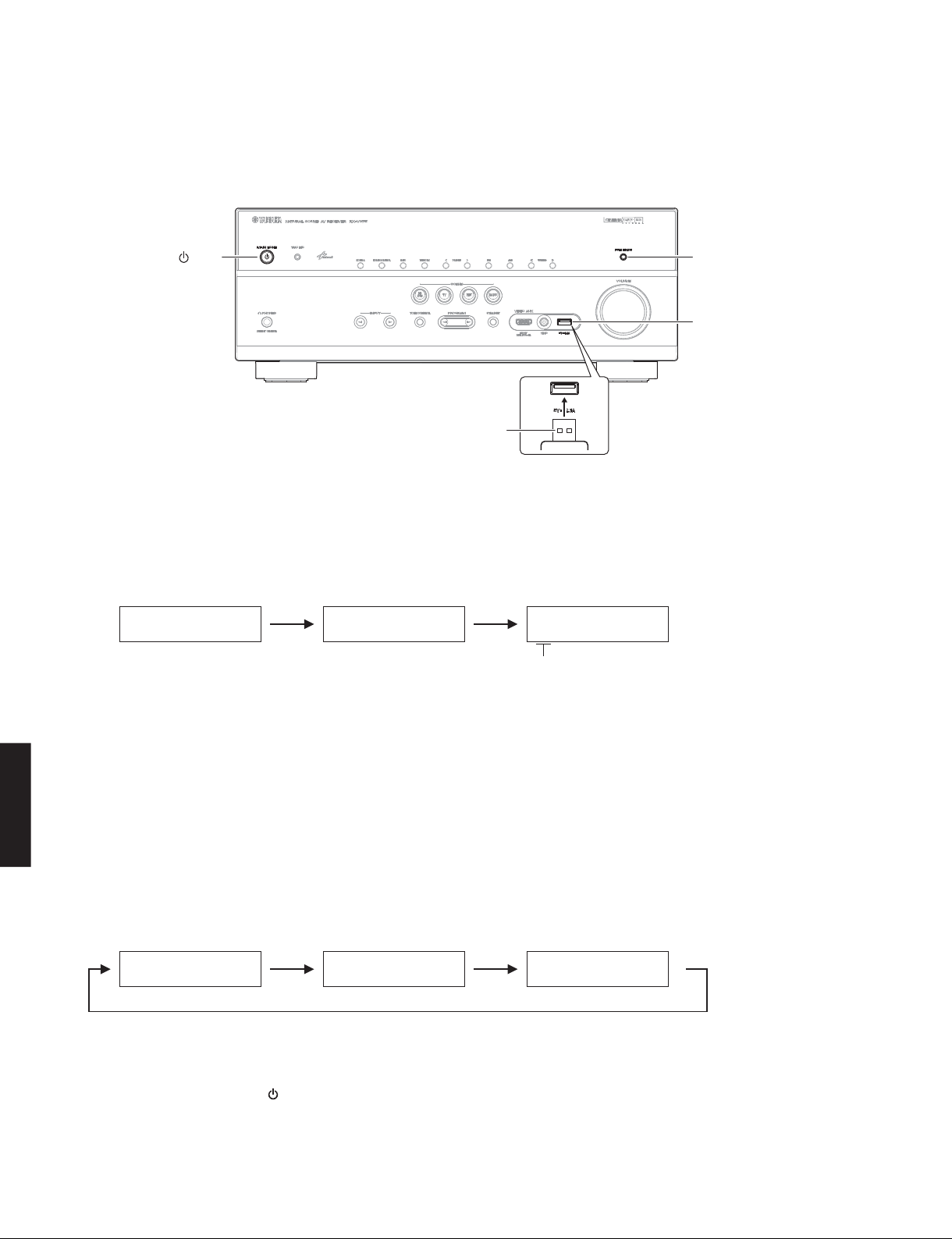
● Operation Procedures
1. Insert the USB storage device to the USB jack. (Fig. 1)
2. While pressing the “PURE DIRECT” key, connect the power cable to the AC outlet. (Fig. 1)
"MAIN ZONE " key "PURE DIRECT" key
USB jack
USB storage device
Fig. 1
RX-A730/TSR-6750
RX-V675/HTR-6066/
3. The USB UPDATE mode is activated and “USB UPDATE” is displayed. Writing of the firmware starts automatically.
(Fig. 2)
Writing is started.
USBUPDATE
VERIFYING...
Writing being executed.
Sx-x:xx%
S1: NET (IC951/IC953 on DIGITAL (1) P.C.B.) section
S2: MAIN (IC83 on DIGITAL (1) P.C.B.) section
S3: DSP1 (IC921/IC923 on DIGITAL (1) P.C.B.) section
S4: DSP2 section (Not available)
S5: GUI (IC50/IC77 on DIGITAL (1) P.C.B.) section
Fig. 2
* If “ERROR! xxxx” is displayed during writing of the firmware, refer to “List of Error Messages” to determine the
cause and perform the updating procedure again from the beginning.
4. When writing of the firmware is completed, “UPDATE SUCCESS”, “PLEASE...” and “POWER OFF!” are displayed
repeatedly. (Fig. 3)
Writing is completed.
UPDATESUCCESS
PLEASE...
POWEROFF!
26
Fig. 3
5. Press the “MAIN ZONE
” key to turn off the power. (Fig. 1)
6. Remove the USB storage device from the USB jack. (Fig. 1)
7. Start up the self-diagnostic function and check that the firmware version and checksum are the same as written
ones. (For details, refer to “Confirmation of firmware version and checksum”)
RX-V675/HTR-6066/RX-A730/TSR-6750
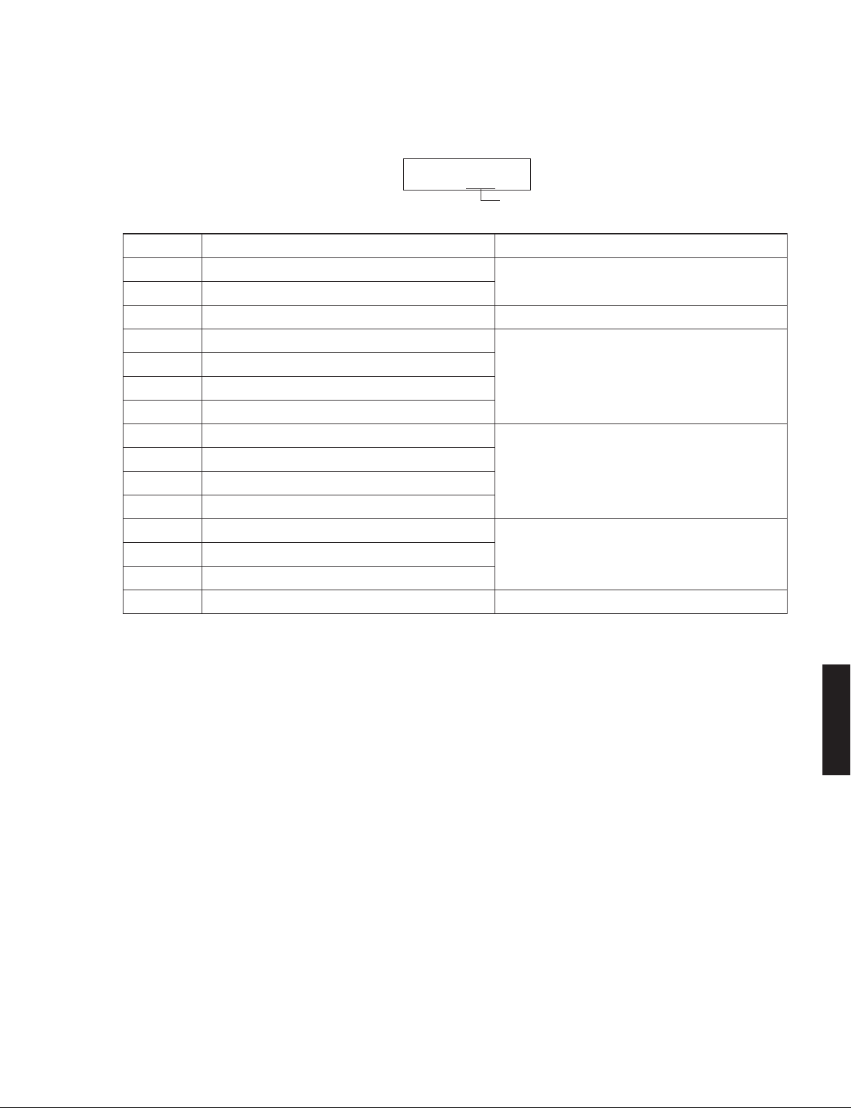
List of Error Messages
Display
ERROR!xxxx
Error number
Error Number Error Message Cause
0001 Microprocessor clearing error Microprocessor failure
0002 Microprocessor writing error
0004 Microprocessor checksum error Microprocessor failure / Mismatch of checksum
0008 DSP1 status port error
0010 DSP1 checksum error
0020 DSP1 data reception time out
0040 DSP1 checksum calculation time out
0080 DSP2 status port error
0100 DSP2 checksum error
0200 DSP2 date reception time out
0400 DSP2 checksum calculation time out
0800 GUI Flash ROM clearing error
1000 GUI Flash ROM writing error
2000 GUI Flash ROM checksum error
4000 Destination judging error No destination is written on EEPROM.
* The error number is displayed in the 4-digit hexadecimal notation.
* The error numbers are added when a multiple number of errors occur at the same time.
Example If errors by the error number “0002” and “0008” occur at the same time, the error number will be displayed as “000A”.
DSP1 failure /
Malfunction of communication with microprocessor
DSP2 failure /
Malfunction of communication with microprocessor
GUI Flash ROM failure /
Malfunction of communication with microprocessor
RX-V675/HTR-6066/
RX-A730/TSR-6750
27
RX-V675/HTR-6066/RX-A730/TSR-6750
■ SELF-DIAGNOSTIC FUNCTION
This unit has self-diagnostic functions that are intended for inspection, measurement and location of faulty point.
There are 26 main menu items, each of which has sub-menu items.
Listed in the table below are main menu items and sub-menu items.
Note: Some of the menu items listed below may not apply to the models covered in this service manual.
No. Main menu No. Sub-menu
A: Audio system
A1 DSP AUDIO 1 DSP MARGIN
A2 DIRECT AUDIO 1 ANALOG DIRECT VH
A3 HDMI AUDIO 1 HDMI AUTO
A4 SPEAKERS SET 1 BI-AMP
RX-A730/TSR-6750
RX-V675/HTR-6066/
A5 MULTI CHANNEL INPUT 1 MULTI CHANNEL INPUT 8 ohms
A6 MIC CHECK 1 MIC ROUTE CHECK
A7 MANUAL TEST 1 TEST ALL
28
(Not for service)
2 DSP NON MARGIN
3 INVALID ITEM
(Not for service)
4 DSP FULL CENTER
5 DSP FULL SURROUND
6 DSP FULL SURROUND BACK
7 DSP FULL SUBWOOFER
2 ANALOG DIRECT VL
2 INVALID ITEM
(Not for service)
3 ARC1
4 INVALID ITEM
5 INVALID ITEM
(Not for service)
(Not for service)
2 ZONE/TONE=MAX
3 ZONE/TONE=MIN
4 INVALID ITEM
5 INVALID ITEM
(Not for service)
(Not for service)
6 D-PARTY MODE
7 FULL MUTE
8 INVALID ITEM
9 INVALID ITEM
10 INVALID ITEM
11 INVALID ITEM
12 INVALID ITEM
13 INVALID ITEM
(Not for service)
(Not for service)
(Not for service)
(Not for service)
(Not for service)
(Not for service)
2 MULTI CHANNEL INPUT 6 ohms
2 TEST FRONT L
3 TEST CENTER
4 TEST FRONT R
5 TEST SURROUND R
6 TEST SURROUND BACK R
7 TEST SURROUND BACK L
8 TEST SURROUND L
9 TEST FRONT PRESENCE L
10 TEST FRONT PRESENCE R
11 INVALID ITEM
12 INVALID ITEM
(Not for service)
(Not for service)
13 TEST LFE 1
14 INVALID ITEM
(Not for service)
RX-V675/HTR-6066/RX-A730/TSR-6750
No. Main menu No. Sub-menu
D: Display system
D1 FL CHECK 1 FL CHECK
2 ALL SEGMENT OFF
3 ALL SEGMENT ON
4 CHECK PATTERN 1
5 CHECK PATTERN 2
Z: Zone system
Z1 ZONE TEST 1 AV1
2AV2
3AV3
4AV4
(Not for service)
(Not for service)
(Not for service)
(Not for service)
5AV5
6AV6
7 AUDIO1
8 AUDIO2
9 V-AUX
10 PHONO
(Not for service)
(Not for service)
U: Universal system
U1 USB 1 USB FRONT 1 TRACK
2 USB FRONT 2 TRACK
3 USB_VBUS HIGH POWER
N: Network system
N1 NETWORK 1 IP ADDRESS CHECK
2 MAC ADDRESS CHECK
3 LINE NOISE 100 MDI
4 LINE NOISE 100 MDIX
5 LINE NOISE 10 MDI
6 LINE NOISE 10 MDIX
(Not for service)
(Not for service)
(Not for service)
(Not for service)
7 EXT TEST
8 MAC ADDRESS
C: Communication system
C1 DIGITAL PCB CHECK 1 ALL
2 BUS FLASH ROM
3 BUS FPGA
4 I2C
5 FPGA RAM
6 BUS DIR
7 BUS DSP
8 EEPROM
9 INVALID ITEM
10 INVALID ITEM
(Not for service)
(Not for service)
C2 NETWORK IC CHECK 1 ALL
2 LINK CHECK
3
PHY TEST
4 BUS RAM
5 APL ID CHECK
RX-V675/HTR-6066/
RX-A730/TSR-6750
29
RX-V675/HTR-6066/RX-A730/TSR-6750
No. Main menu No. Sub-menu
V: Video system
V1 ANALOG VIDEO CHECK 1 ANALOG BYPASS
V2 DIGITAL VIDEO CHECK 1 LOOPBACK TEST 1
V3 TEST PATTERN 1 480i
RX-A730/TSR-6750
RX-V675/HTR-6066/
T: Troubleshooting Information
T1 TROUBLE SHOOTING INFORMATION 1 OPERATING TIME
T2 USAGE ENVIRONMENT 1 MAIN ZONE HIGHEST VOLUME
30
2 INVALID ITEM
3 INVALID ITEM
(Not for service)
(Not for service)
4 MUTE CHECK
5 TEST PATTERN
(Not for service)
6 VIDEO IN
2 LOOPBACK TEST 2
3 LOOPBACK TEST 3
4 INVALID ITEM
5 INVALID ITEM
6 INVALID ITEM
(Not for service)
(Not for service)
(Not for service)
7 HDMI REPEAT
8 DIGITAL CVBS
9 INVALID ITEM
(Not for service)
10 DIGITAL COMPONENT
11 DIGITAL COMPONENT SC
12 GUI-VIDEO OUT
2 480p
3 720p 60Hz
4 1080i 60Hz
5 1080p 60Hz
6 576i
7 576p
8 720p 50Hz
9 1080i 50Hz
10 1080p 50Hz
11 1080p 24Hz
12 1080p 24Hz 3D/FP
13 720p 60Hz 3D/FP
14 720p 50Hz 3D/FP
15 1080i 60Hz 3D/FP
16 1080i 60Hz 3D/SS
17 1080i 50Hz 3D/SS
18 720p 60Hz 3D/TB
19 720p 50Hz 3D/TB
20 1080p 24Hz 3D/TB
21 4k 24Hz
2 POWER-RELAY ON
3 POWER AMP B
4 OUTPUT LEVEL
5 POWER OFF TIME-OUT
2 ZONE 2 HIGHEST VOLUME
3 INVALID ITEM
(Not for service)
4 THM1/THM2 HIGHEST TEMPERATURE
5 THM3/THM4 HIGHEST TEMPERATURE
(Not for service)
 Loading...