

Yamaha Grizzly 550 YFM5FGA, Grizzly 550 YFM5FGPHA, Grizzly 550 YFM5FGHA, Grizzly 550 YFM5FGPA, Grizzly 700 YFM7FGPA Owner's Manual
...
READ THIS MANUAL CAREFULLY!
It contains important safety information.
OWNER’S MANUAL
YFM7FGPSEZ
WARNING
This ATV should not be ridden by anyone under 16 years of age.
43P-28199-12LIT-11626-23-52
EBU17092
Read this manual carefully before operating this vehicle. This manual should stay with this ve-
hicle if it is sold.

EBU17170
INTRODUCTION
EBU17272
Congratulations on your purchase of the Yamaha YFM7FGPSEZ. This ATV represents the result of many
years of Yamaha experience in the production of fine sporting, touring, and pace-setting racing machines.
With the purchase of this Yamaha, you can now appreciate the high degree of craftsmanship and reliability
that have made Yamaha a leader in these fields.
This manual will provide you with a good basic understanding of the features and operation of this ATV.
This manual includes important safety information. It provides information about special techniques and skills necessary to ride the ATV. It also includes basic maintenance and inspection proce-
dures. If you have any questions regarding the operation or maintenance of your ATV, please consult a
Yamaha dealer.
AN IMPORTANT SAFETY MESSAGE:
● Read this manual together with TIPS FOR THE ATV RIDER carefully and completely before operating
your ATV. Make sure you understand all instructions.
● Pay close attention to the warning and notice labels on the ATV.
● Never operate an ATV without proper training or instruction. Free training is available to anyone who buys
a new ATV. Call 1-800-887-2887 for more information.
● This ATV should not be ridden by anyone under 16 years of age.

EBU17330
IMPORTANT MANUAL INFORMATION
EBU17342
FAILURE TO FOLLOW THE WARNINGS CONTAINED IN THIS MANUAL CAN RESULT IN SERIOUS INJURY OR DEATH.
Particularly important information is distinguished in this manual by the following notations:
This is the safety alert symbol. It is used to alert you to potential personal injury hazards. Obey all safety messages that follow this symbol to avoid possible injury or death.
WARNING
NOTICE
TIP
A WARNING indicates a hazardous situation which, if not avoided,
could result in death or serious injury.
A NOTICE indicates special precautions that must be taken to avoid
damage to the vehicle or other property.
A TIP provides key information to make procedures easier or clearer.
* Product and specifications are subject to change without notice.

EBU17350
IMPORTANT NOTICE
EBU17362
This ATV is designed and manufactured for off-road use only. It is illegal and unsafe to operate this ATV on
any public street, road or highway.
This ATV complies with all applicable off-road noise level and spark arrester laws and regulations in effect
at the time of manufacture.
Please check your local riding laws and regulations before operating this ATV.
EBU17382
YFM7FGPSEZ
OWNER’S MANUAL
©2009 by Yamaha Motor Corporation, U.S.A.
1st edition, July 2009
All rights reserved.
Any reprinting or unauthorized use
without the written permission of
Yamaha Motor Corporation, U.S.A.
is expressly prohibited.
Printed in Japan.
P/N LIT-11626-23-52

EWB00011
WARNING
Indicates a hazardous situation which, if not
avoided, could result in death or serious injury.
EBU17420
TABLE OF CONTENTS
LOCATION OF THE WARNING AND
SPECIFICATION LABELS ............................ 1-1
SAFETY INFORMATION .............................. 2-1
Speed limiter .............................................4-13
Front brake lever .......................................4-14
Brake pedal and rear brake lever .............4-14
Drive select lever ......................................4-15
Fuel tank cap ............................................4-15
Fuel ...........................................................4-16
Seat ..........................................................4-18
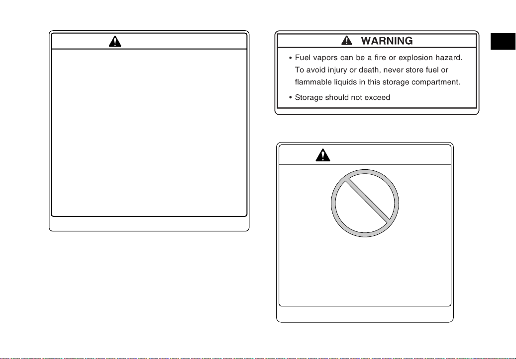
Storage compartments .............................4-19
Front carrier ..............................................4-22
Rear carrier ...............................................4-22
Adjusting the front and rear shock
absorber assemblies ...............................4-22
Auxiliary DC jack .......................................4-23
DESCRIPTION .............................................. 3-1
Left view ...................................................... 3-1
Right view.................................................... 3-1
Controls and instruments ............................ 3-2
INSTRUMENT AND CONTROL
FUNCTIONS .................................................. 4-1
Main switch ................................................ 4-1
Indicator lights and warning lights .............. 4-2
Multi-function display .................................. 4-5
Handlebar switches .................................... 4-7
Throttle lever ............................................ 4-13
PRE-OPERATION CHECKS ..........................5-1
Fuel .............................................................5-3
Engine oil ....................................................5-3
Final gear oil ...............................................5-3
Differential gear oil ......................................5-3
Coolant .......................................................5-3
Front and rear brakes .................................5-3
Throttle lever ...............................................5-4
Tires ............................................................5-4
Chassis fasteners .......................................5-6
Instruments, lights and switches .................5-7

OPERATION .................................................. 6-1
Starting the engine ..................................... 6-1
Operating the drive select lever and
driving in reverse ...................................... 6-2
Engine break-in .......................................... 6-4
Parking ....................................................... 6-5
Parking on a slope ..................................... 6-5
Accessories and loading ............................ 6-6
RIDING YOUR ATV ...................................... 7-1
GETTING TO KNOW YOUR ATV............... 7-2
RIDE WITH CARE AND GOOD
JUDGMENT .............................................. 7-2
BE CAREFUL WHERE YOU RIDE............. 7-9
TURNING YOUR ATV .............................. 7-12
CLIMBING UPHILL ................................... 7-13
RIDING DOWNHILL.................................. 7-16
CROSSING A SLOPE............................... 7-17
CROSSING THROUGH SHALLOW
WATER ................................................... 7-18
RIDING OVER ROUGH TERRAIN ........... 7-21
SLIDING AND SKIDDING ......................... 7-21
WHAT TO DO IF... .................................... 7-22
WHAT TO DO... ........................................ 7-23
PERIODIC MAINTENANCE AND
ADJUSTMENT................................................8-1
Owner’s manual and tool kit .......................8-1
Periodic maintenance chart for the
emission control system ...........................8-3
General maintenance and lubrication
chart ..........................................................8-4
Removing and installing panels ..................8-8
Removing the radiator grills ......................8-20
Checking the spark plug ...........................8-20
Engine oil and oil filter cartridge ................8-22
Final gear oil .............................................8-26
Differential gear oil ....................................8-29
Coolant .....................................................8-31
Cleaning the air filter element ...................8-37
Cleaning the spark arrester ......................8-41
V-belt case drain plug ...............................8-42
Adjusting the throttle cable free play .........8-43
Valve clearance ........................................8-44
Adjusting the drive select lever safety
system cable ...........................................8-44
Brakes .......................................................8-44
Checking the front and rear brake pads ...8-44
Checking the rear brake hose
protectors ................................................8-45
Checking the brake fluid level ...................8-46
Changing the brake fluid ...........................8-47

Checking the front and rear brake lever
free play ................................................. 8-47
Adjusting the brake pedal free play .......... 8-48
Axle boots ................................................ 8-50
Checking and lubricating the cables ........ 8-51
Checking and lubricating the front and
rear brake levers .................................... 8-51
Checking and lubricating the brake
pedal ...................................................... 8-52
Checking the wheel hub bearings ............ 8-53
Checking the stabilizer bushes ................ 8-53
Lubricating the rear knuckle pivots ........... 8-53
Lubricating the steering shaft ................... 8-54
Battery ...................................................... 8-54
Replacing a fuse ...................................... 8-57
Replacing a headlight bulb ....................... 8-59
Adjusting a headlight beam ...................... 8-61
Replacing the tail/brake light bulb ............ 8-61
Removing a wheel .................................... 8-62
Installing a wheel ...................................... 8-63
Troubleshooting ....................................... 8-64
Troubleshooting charts ............................. 8-65
CLEANING AND STORAGE.......................... 9-1
Cleaning ..................................................... 9-1
Storage ....................................................... 9-2
SPECIFICATIONS .......................................10-1
CONSUMER INFORMATION.......................11-1
Identification numbers ...............................11-1
Noise regulation ........................................11-4
Maintenance record ..................................11-5
YAMAHA MOTOR CORPORATION,
U.S.A. ATV LIMITED WARRANTY .........11-6
YAMAHA EXTENDED SERVICE
(Y.E.S.) ...................................................11-8

EBU17660
LOCATION OF THE WARNING AND SPECIFICATION LABELS
123
4
9
8
7
5
6
1
10
11
1-1

EBU17670
Read and understand all of the labels on your ATV. These labels contain important information for safe and
1
proper operation.
Never remove any labels from your ATV. If a label becomes difficult to read or comes off, request a replacement label from your Yamaha dealer.
99 lbs. (45 kg)
3B4-24875-U0
1-2
187 lbs. (85 kg)
5880 N (600 kgf)
1322 lbf
147 N ( 15 kgf)
33 lbf
3B4-24875-S0
43P-2151K-00
56
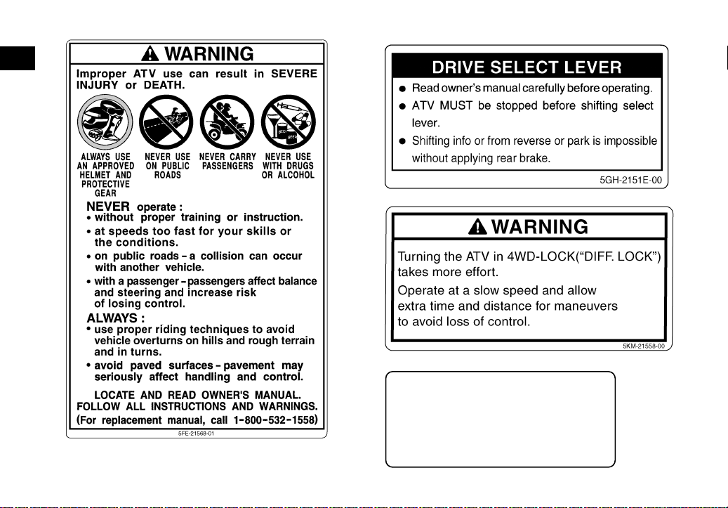
WARNING
Improper tire pressure or overloading can cause
loss of control.
Loss of control can result in severe injury or
death.
OPERATING TIRE PRESSURE : Set with tires cold
• Recommended : Front : 5.0 psi (35.0 kPa)
Rear : 4.4 psi (30.0 kPa)
• Minimum : Front : 4.6 psi (32.0 kPa)
Rear : 4.0 psi (27.0 kPa)
• Never set tire pressure below minimum.
It could cause the tire to dislodge from the rim.
LOADING / TRAILER TOWING
• Cargo or a trailer can affect stability and handling.
Read owner’s manual before loading or towing.
• When loading with cargo or towing a trailer :
Reduce speed and allow more room to stop.
Avoid hills and rough terrain.
• Maximum weight capacity : 485 lbs. (220 kg)
Includes weight of operator, cargo and accessories
(and if applicable, trailer tongue weight).
28P-2816M-U0
7
WARNING
UNDER
16
Operating this ATV if you are under
the age of 16 increases your
chance of severe injury or death.
NEVER
under age 16.
operate this ATV if you are
4D3-2816L-00
1 lb (0.5 kg).
3B4-2151F-U0
1
1-3
89
1
10
11
This ATV complies with applicable provisions of
ANSI/SVIA 1-2007 and is subject to an approved
ATV action plan submitted by YAMAHA and on file
with the U.S. Consumer Product safety Commission.
Certification of Compliance
YAMAHA MOTOR CORPORATION U.S.A.
6555 Katella Avenue, Cypress, California 90630-5101, U.S.A.
1-4
43P-2817J-00
EBU17431
SAFETY INFORMATION
EBU27232
AN ATV IS NOT A TOY AND CAN BE HAZARDOUS TO OPERATE.
An ATV handles differently from other vehicles, including motorcycles and cars. A collision or rollover can occur quickly, even during routine
maneuvers such as turning and riding on hills or
over obstacles, if you fail to take proper precautions.
SEVERE INJURY OR DEATH can result if you do
not follow these instructions:
● Read this manual and all labels carefully and fol-
low the operating procedures described.
● Never operate an ATV without proper training or
instruction. Take a Training Course.
Beginners
should receive training from a certified instructor. Contact an authorized ATV dealer or call 1800-887-2887 to find out about the training
courses nearest you.
● Always follow the age recommendation:
– A child under 16 years old should never operate an ATV with engine size greater than 90 cc.
● Never allow a child under age 16 to operate an
ATV without adult supervision, and never allow
continued use of an ATV by a child if he or she
does not have the abilities to operate it safely.
● Never carry a passenger on an ATV.
● Always avoid operating an ATV on any paved
surfaces, including sidewalks, driveways, parking lots and streets.
● Never operate an ATV on any public street, road
or highway, even a dirt or gravel one.
● Never operate an ATV without wearing an ap-
proved motorcycle helmet that fits properly. You
should also wear eye protection (goggles or face
shield), gloves, boots, a long-sleeved shirt or a
jacket, and long pants.
● Never consume alcohol or drugs before or while
operating this ATV.
● Never operate at speeds too fast for your skills
or the riding conditions. Always go at a speed
that is proper for the terrain, visibility, operating
conditions, and your experience.
● Never attempt wheelies, jumps, or other stunts.
2-1
2

● Always inspect your ATV each time you use it to
make sure it is in safe operating condition. Always follow the inspection and maintenance
procedures and schedules described in this
2
manual.
● Always keep both hands on the handlebars and
both feet on the footboards of the ATV during
operation.
● Always go slowly and be extra careful when op-
erating on unfamiliar terrain. Always be alert to
changing terrain conditions when operating the
ATV.
● Never operate on excessively rough, slippery or
loose terrain until you have learned and practiced the skills necessary to control the ATV on
such terrain. Always be especially cautious on
these kinds of terrain.
● Always follow proper procedures for turning as
described in this manual. Practice turning at low
speeds before attempting to turn at faster
speeds and never turn at excessive speeds.
● Never operate the ATV on hills too steep for the
ATV or for your abilities. Practice on smaller hills
before attempting larger hills.
● Always follow proper procedures for climbing
hills as described in this manual. Check the terrain carefully before you start up any hill. Never
climb hills with excessively slippery or loose surfaces. Shift your weight forward. Never open the
throttle suddenly. Never go over the top of a hill
at high speed.
● Always follow proper procedures for going down
hills and for braking on hills as described in this
manual. Check the terrain carefully before you
start down any hill. Shift your weight backward.
Never go down a hill at high speed. Avoid going
down a hill at an angle that would cause the vehicle to lean sharply to one side. Go straight
down the hill where possible.
● Always follow proper procedures for crossing
the side of a hill as described in this manual.
Avoid hills with excessively slippery or loose surfaces. Shift your weight to the uphill side of the
ATV. Never attempt to turn the ATV around on
any hill until you have mastered the turning technique described in this manual on level ground.
Avoid crossing the side of a steep hill if possible.
● Always use proper procedures if you stall or roll
backwards when climbing a hill. To avoid stalling, use the proper gear range and maintain a
2-2

steady speed when climbing a hill. If you stall or
roll backwards, follow the special procedure for
braking described in this manual. Dismount on
the uphill side or to a side if pointed straight uphill. Turn the ATV around and remount, following
the procedure described in this manual.
● Always check for obstacles before operating in a
new area.
● Never attempt to operate over large obstacles,
such as large rocks or fallen trees. Always follow
proper procedures when operating over obstacles as described in this manual.
● Always be careful when skidding or sliding.
Learn to safely control skidding or sliding by
practicing at low speeds and on level, smooth
terrain. On extremely slippery surfaces, such as
ice, go slowly and be very cautious in order to reduce the chance of skidding or sliding out of control.
● Never operate an ATV in fast flowing water or in
water deeper than that recommended in this
manual. Remember that wet brakes may have
reduced stopping ability. Test your brakes after
leaving water. If necessary, apply them several
times to let friction dry out the linings.
● Always be sure there are no obstacles or people
behind you when you operate in reverse. When
it is safe to proceed in reverse, go slowly.
● Always use the size and type of tires specified in
this manual.
● Always maintain proper tire pressure as de-
scribed in this manual.
● Never modify an ATV through improper installa-
tion or use of accessories.
● Never exceed the stated load capacity for an
ATV. Cargo should be properly distributed and
securely attached. Reduce speed and follow instructions in this manual for carrying cargo or
pulling a trailer. Allow greater distance for braking.
2
2-3

EWB00071
WARNING
Avoid Carbon Monoxide Poisoning
All engine exhaust contains carbon monoxide,
2
a deadly gas. Breathing carbon monoxide can
cause headaches, dizziness, drowsiness, nausea, confusion, and eventually death.
Carbon Monoxide is a colorless, odorless,
tasteless gas which may be present even if you
do not see or smell any engine exhaust. Deadly
levels of carbon monoxide can collect rapidly
and you can quickly be overcome and unable
to save yourself. Also, deadly levels of carbon
monoxide can linger for hours or days in enclosed or poorly ventilated areas. If you experience any symptoms of carbon monoxide
poisoning, leave the area immediately, get
fresh air, and SEEK MEDICAL TREATMENT.
● Do not run engine indoors. Even if you try to
ventilate engine exhaust with fans or open
windows and doors, carbon monoxide can
rapidly reach dangerous levels.
● Do not run engine in poorly ventilated or par-
tially enclosed areas such as barns, garages,
or carports.
● Do not run engine outdoors where engine
exhaust can be drawn into a building
through openings such as windows and
doors.
FOR MORE INFORMATION ABOUT ATV SAFETY, call the Consumer Products Safety Commis-
sion at 1-800-638-2772, or the ATV Distributor’s
Safety Hotline at 1-800-852-5344.
2-4

EBU17680
DESCRIPTION
EBU17690
Left view
1. Radiator cap
2. Battery
3. Fuses
4. Air filter case
5. Spark arrester
6. Engine oil dipstick
7. Oil filter cartridge
8. Coolant reservoir
EBU17700
Right view
5
3
1. Rear shock absorber assembly spring preload adjusting
ring
2. Rear storage compartment and tool kit
3. Fuel tank cap cover
4. Front shock absorber assembly spring preload adjusting
ring
5. Spark plug
6. Brake pedal
7. V-belt case drain plug
3-1
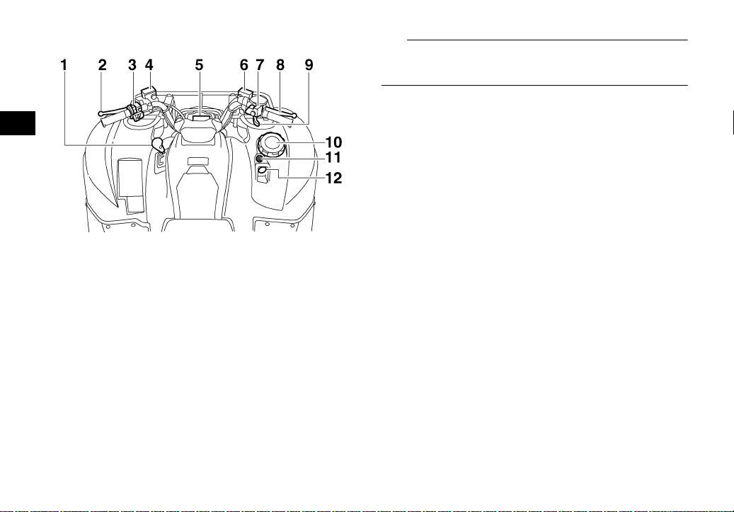
EBU17712
Controls and instruments
3
1. Drive select lever
2. Rear brake lever
3. Handlebar switches
4. Rear brake fluid reservoir
5. Multi-function display
6. Front brake fluid reservoir
7. On-Command four-wheel-drive/differential gear lock
switch
8. Front brake lever
9. Throttle lever
10.Front storage compartment
11.Main switch
12.Auxiliary DC jack
TIP
The ATV you have purchased may differ slightly
from the figures shown in this manual.
3-2

EBU17725
INSTRUMENT AND CONTROL FUNCTIONS
EWB00011
WARNING
Indicates a hazardous situation which, if not
avoided, could result in death or serious injury.
EBU17760
Main switch
The positions of the main switch are as follows:
ON
All electrical systems are supplied with power. The
headlights and taillight come on when the light
switch is on, and the engine can be started. The
key cannot be removed.
OFF
All electrical systems are off. The key can be removed.
4
1. Main switch
4-1
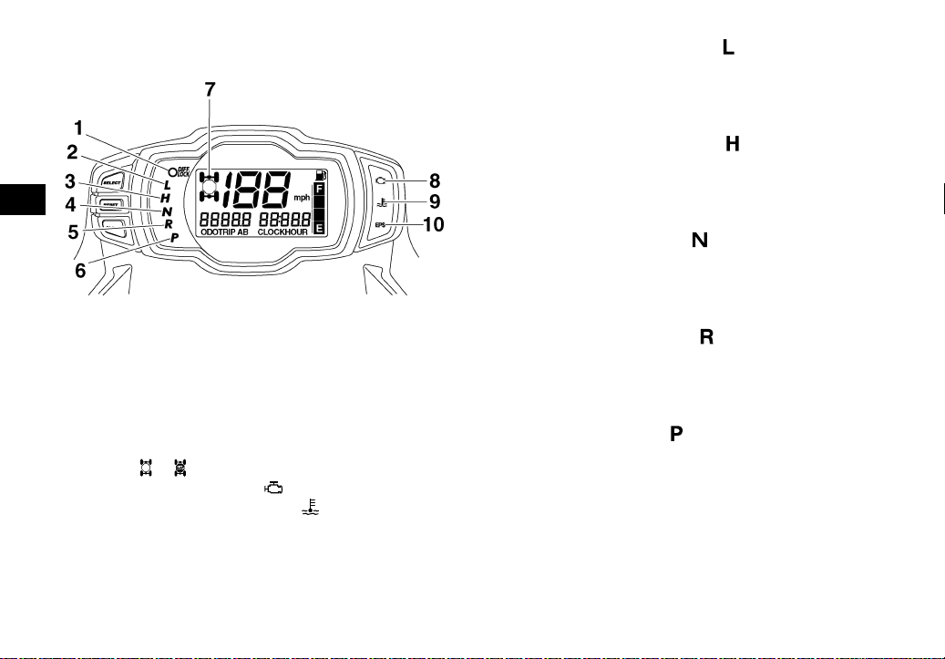
EBU26694
Indicator lights and warning lights
4
1. On-Command differential gear lock indicator light “DIFF.
LOCK”
2. Low-range indicator light “L”
3. High-range indicator light “H”
4. Neutral indicator light “N”
5. Reverse indicator light “R”
6. Park indicator light “P”
7. On-Command four-wheel-drive/differential gear lock
indicator “”/“”
8. Engine trouble warning light “”
9. Coolant temperature warning light “”
10.Electric Power Steering warning light “EPS”
EBU17990
Low-range indicator light “”
This indicator light comes on when the transmission is in the low-range position.
EBU17980
High-range indicator light “”
This indicator light comes on when the transmission is in the high-range position.
EBU17860
Neutral indicator light “”
This indicator light comes on when the transmission is in the neutral position.
EBU17830
Reverse indicator light “”
This indicator light comes on when the transmission is in the reverse position.
EBU17970
Park indicator light “”
This indicator light comes on when the transmission is in the park position.
4-2

EBU28664
Coolant temperature warning light “”
This warning light comes on when the engine overheats. When this occurs during operation, stop the
engine as soon as it is safe to do so and allow it to
cool down for about 10 minutes.
The electrical circuit of the warning light can be
checked by turning the key to “ON”. The warning
light should come on for a few seconds, and then
go off.
If the warning light does not come on initially when
the key is turned to “ON”, or if the warning light remains on, have a Yamaha dealer check the electrical circuit.
ECB00891
NOTICE
● The engine may overheat if the ATV is over-
loaded. In this case, reduce the load to specification.
● The engine may also overheat if mud or dirt
has accumulated on the radiator (i.e., after
riding in wet terrain). In this case, see page
8-20 for an explanation on how to access the
radiator.
● Start the engine after making sure that the
warning light is out. Continuous use while
the warning light is on may cause damage to
the engine.
EBU27284
Engine trouble warning light “”
This warning light comes on or flashes when an
electrical circuit monitoring the engine is not working correctly. When this occurs, have a Yamaha
dealer check the self-diagnosis system. (See page
4-7 for an explanation of the self-diagnosis device.)
The electrical circuit of the warning light can be
checked by turning the key to “ON”. The warning
light should come on for a few seconds, and then
go off.
If the warning light does not come on initially when
the key is turned to “ON”, or if the warning light remains on, have a Yamaha dealer check the electrical circuit.
EBU27543
Electric Power Steering warning light “EPS”
This warning light comes on when the key is turned
to “ON”, and then goes off once the engine is started. If the warning light remains on or comes on af-
4
4-3
ter the engine is started, the EPS system may not
be working correctly. When this occurs, have a
Yamaha dealer check the EPS system.
The electrical circuit of the warning light can be
checked by turning the key to “ON”. If the warning
light does not come on, have a Yamaha dealer
check the electrical circuit.
TIP
4
● If the engine is stopped using the engine stop
switch and the key is in the “ON” position, the
EPS warning light comes on to indicate that the
power assistance for the steering is not functioning.
● If the steering load is too heavy (i.e., excessive
steering use when the ATV is traveling at a slow
speed), the power assist is reduced to protect
the EPS motor from overheating.
EBU29621
On-Command four-wheel-drive indicator “”,
On-Command differential gear lock
indicator “” and indicator light “DIFF.
LOCK”
The On-Command four-wheel-drive indicator “”
comes on when the On-Command four-wheeldrive switch is set to the “4WD” position.
The On-Command differential gear lock
indicator “” and the On-Command differential
gear lock indicator light “DIFF. LOCK” come on
when the On-Command differential gear lock
switch is set to the “LOCK” position.
TIP
● Due to the synchronizing mechanism in the dif-
ferential gear case, the four-wheel-drive indicator may not come on until the ATV starts moving.
● When the On-Command differential gear lock
switch is set to “LOCK”, the indicator “” and
the indicator light “DIFF. LOCK” will flash until
the differential gear is locked. If the indicator and
the indicator light continue to flash, the differential is not locked. In this case, start moving to allow time for the differential to lock.
4-4

EBU27298
Multi-function display
1. “CLOCK” button
2. “RESET” button
3. “SELECT” button
4. Speedometer
5. Fuel meter
6. Clock/Hour meter
7. Odometer/Tripmeter A/Tripmeter B
The multi-function display is equipped with the following:
● a speedometer
● an odometer
● two tripmeters (which show the distance trav-
eled since they were last set to zero)
● a clock
● an hour meter (which shows the total time the
engine has been running)
● a fuel meter
● a self-diagnosis device
Odometer and tripmeter modes
Pushing the “SELECT” button switches the display
between the odometer mode “ODO” and the tripmeter modes “TRIP A” and “TRIP B” in the following order:
ODO → TRIP A → TRIP B → ODO
To reset a tripmeter, select it by pushing the “SE-
LECT” button, and then push the “RESET” button
for at least three seconds. The tripmeters can be
used to estimate the distance that can be traveled
with a full tank of fuel. This information will enable
you to plan future fuel stops.
TIP
Pushing and holding in the “SELECT” button, and
turning the key to “ON” while the button is pushed,
switches the display between “mph” and “km/h”.
Clock mode
Pushing the “CLOCK” button switches the display
between the clock mode “CLOCK” and the hour
meter mode “HOUR” in the following order:
4-5
4

CLOCK → HOUR → CLOCK
To set the clock
1. Set the display to the clock mode.
2. Push the “SELECT” button and “RESET” but-
ton together for at least three seconds.
3. When the hour digits start flashing, push the
“RESET” button to set the hours.
4
4. Push the “SELECT” button, and the minute
digits will start flashing.
5. Push the “RESET” button to set the minutes.
6. Push the “SELECT” button and then release it
to start the clock.
Fuel meter
The fuel meter indicates the amount of fuel in the
fuel tank. The display segments of the fuel meter
disappear from “F” (full) towards “E” (empty) as the
fuel level decreases. When the “E” segment disappears and the fuel level warning indicator flashes,
refuel as soon as possible.
TIP
This fuel meter is equipped with a self-diagnosis
system. If the electrical circuit is not working correctly, all the display segments and fuel level warning indicator will start flashing. If this occurs, have
a Yamaha dealer check the electrical circuit.
1. Fuel level warning indicator
2. Fuel meter
3. “E” segment
4-6

Self-diagnosis device
EBU18061
Handlebar switches
4
1. Error code display
This model is equipped with a self-diagnosis device for various electrical circuits.
If a problem is detected in any of those circuits, the
multi-function display will indicate an error code.
If the multi-function display indicates an error code,
note the code number, and then have a Yamaha
dealer check the vehicle.
ECB00811
NOTICE
If the multi-function display indicates an error
code, the vehicle should be checked as soon
as possible in order to avoid engine damage.
1. Light switch “ //OFF”
2. Start switch “”
3. Engine stop switch “ / ”
4. Override switch “OVERRIDE”
EBU18080
Engine stop switch “ / ”
Set this switch to “” before starting the engine.
The engine stop switch controls the ignition and
stops the engine when it is running. Use this switch
to stop the engine in an emergency situation. The
engine will not start or run when this switch is set
to “”.
4-7
EBU18101
Start switch “”
Push this switch to crank the engine with the starter. See the starting instructions on page 6-1 prior
to starting the engine.
EBU18152
Light switch “ //OFF”
Set this switch to “” to turn on the low beams
4
and the taillight. Set the switch to “” to turn on
the high beams and the taillight. Set the switch to
“OFF” to turn off all the lights.
ECB00041
NOTICE
Do not use the headlights with the engine
turned off for an extended period of time, otherwise the battery may discharge to the point
that the starter motor will not operate properly.
If this should happen, remove the battery and
recharge it. See page 8-54 for battery charging
information.
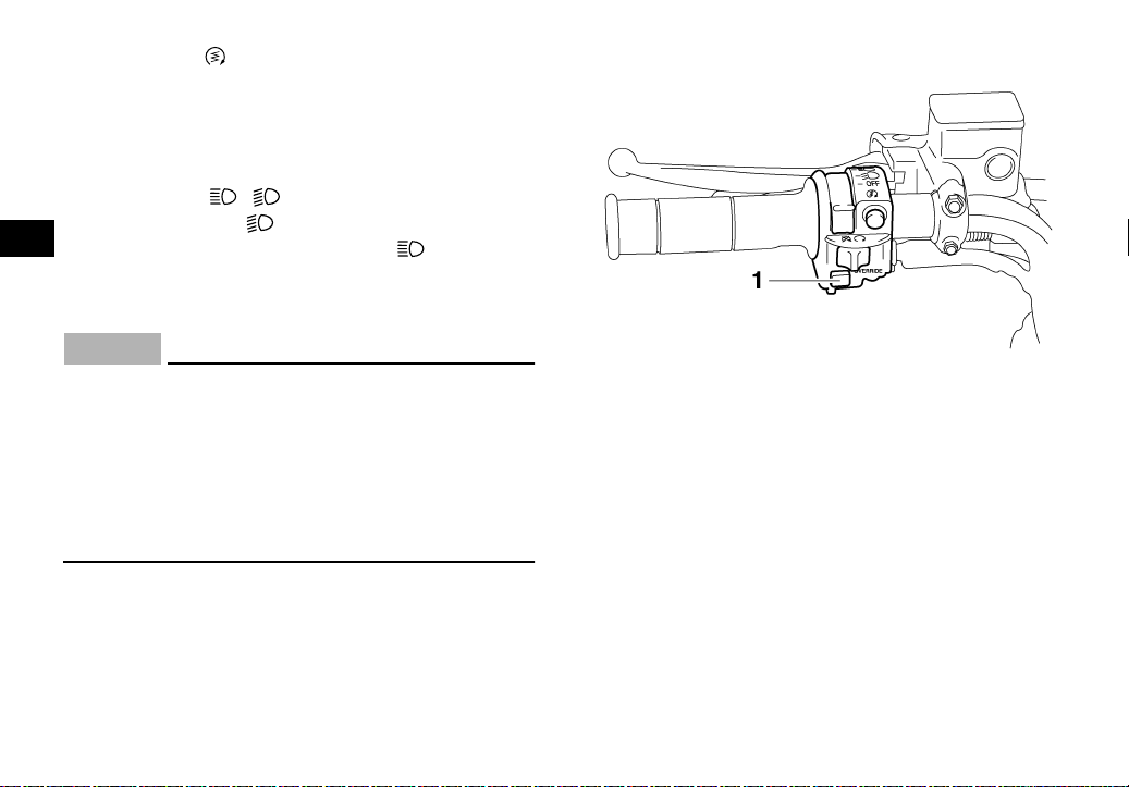
EBU18190
Override switch “OVERRIDE”
1. Override switch “OVERRIDE”
Top speed is normally limited when operating in
differential gear lock. If conditions require more engine power when riding forward, push and hold this
switch to override the differential gear lock speed
limiting function. (See page 4-10.) Releasing the
switch restores the speed limiting function.
While the override switch is pushed, the segments
of the speedometer digits will appear as shown in
the figure.
4-8
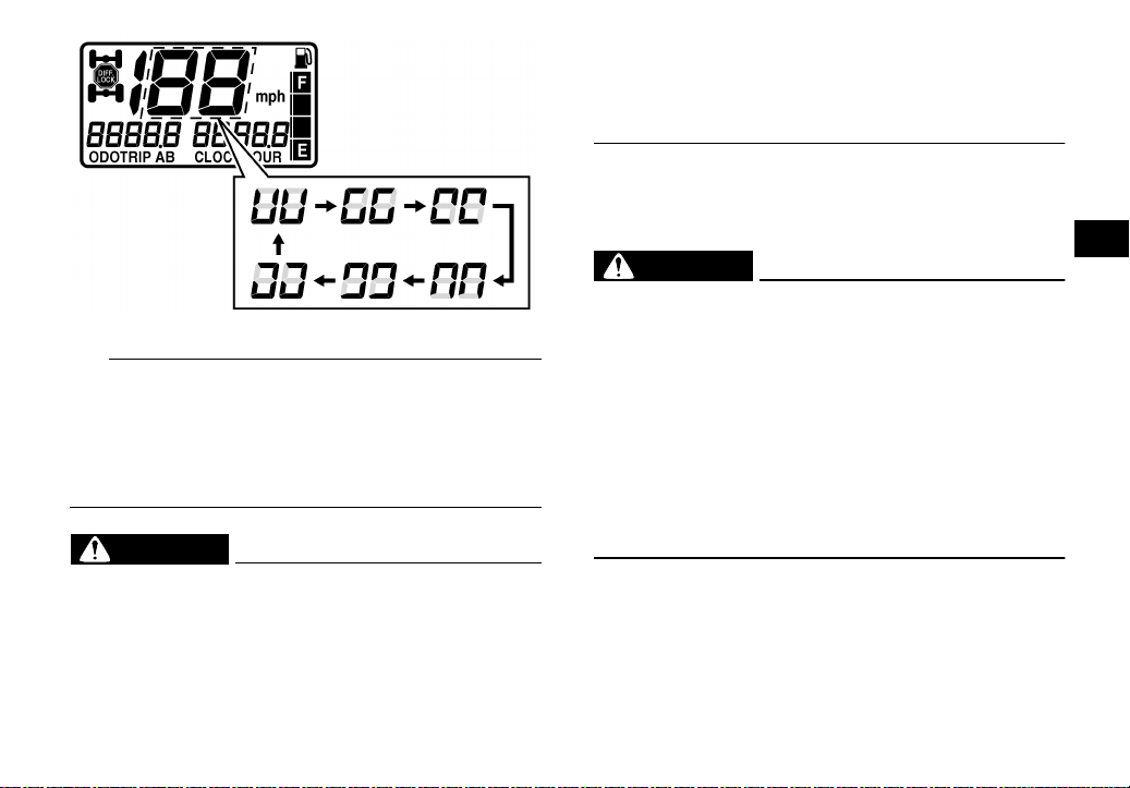
TIP
If the digits of the speedometer appear as shown
when the switch is NOT being pushed, this could
indicate a malfunction in the electrical system. In
this case, take the ATV to a Yamaha dealer at the
first opportunity.
EWB00150
WARNING
Always ride at a slow speed when the ATV is in
four-wheel-drive differential gear lock, and allow extra time and distance for maneuvers.
All wheels turn at the same speed when the differential is locked, so it takes more effort to
turn the ATV. The effort needed to turn increas-
es with the riding speed. You may lose control
and have an accident if you cannot make a
sharp enough turn for the speed you are traveling.
EBU26606
On-Command four-wheel-drive switch
“2WD”/“4WD”
EWB00163
WARNING
Always stop the ATV before changing from
two-wheel drive to four-wheel drive and vice
versa. The ATV handles differently in twowheel drive than in four-wheel drive in some
circumstances. Changing from two-wheel
drive to four-wheel drive or vice versa while
moving may cause the ATV to unexpectedly
handle differently. This could distract the operator and increase the risk of losing control and
of causing an accident.
This ATV is equipped with a switch to change from
two-wheel drive to four-wheel drive and vice versa.
Select the appropriate drive according to the terrain and the conditions.
● “2WD” (two-wheel drive): Power is supplied to
the rear wheels.
4-9
4
● “4WD” (four-wheel drive): Power is supplied to
the rear and front wheels.
To change from two-wheel drive to four-wheel
drive, stop the ATV and push the switch in to the
“4WD” position. Then, the four-wheel-drive
indicator “” comes on in the multi-function dis-
play.
To change from four-wheel drive to two-wheel
4
drive, stop the ATV and push the switch in to the
“2WD” position.
2WD
4WD
1. On-Command four-wheel-drive switch “2WD”/“4WD”
EBU18255
On-Command differential gear lock switch
“4WD”/“LOCK”
EWB00131
WARNING
Always stop the ATV before changing from
four-wheel drive to four-wheel-drive differential gear lock or vice versa.
The ATV handles differently in four-wheel drive
than in differential gear lock in some circumstances. Changing from four-wheel drive to differential gear lock or vice versa while moving
1
may cause the ATV to handle differently unexpectedly. This could distract the operator and
increase the risk of losing control and causing
an accident.
EWB00140
WARNING
Always ride at a slow speed when the ATV is in
differential gear lock, and allow extra time and
distance for maneuvers.
All wheels turn at the same speed when the differential gear is locked, so it takes more effort
to turn the ATV. The effort needed to turn increases with the riding speed. You may lose
4-10
control and have an accident if you cannot
make a sharp enough turn for the speed you
are traveling.
2
1
This ATV is equipped with a switch allowing you to
lock the differential gear when in four-wheel drive.
Select the appropriate switch position according to
the terrain and the conditions.
● “4WD” (four-wheel drive): Power is supplied to
the rear and front wheels.
● “LOCK” (four-wheel drive with the differential
gear locked): Power is supplied to the rear and
front wheels and the differential gear is locked.
Unlike in four-wheel drive, all wheels turn at the
same speed.
2WD
4WD
1. On-Command four-wheel-drive switch “2WD”/“4WD”
2. On-Command differential gear lock switch “4WD”/“LOCK”
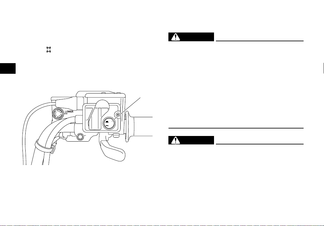
To lock the differential gear in four-wheel drive,
make sure the On-Command four-wheel-drive
switch is pushed in to the “4WD” position.
4-11
4

1
2
1
2WD
4WD
4
1. Differential gear lock lever
2. On-Command four-wheel-drive switch “2WD”/“4WD”
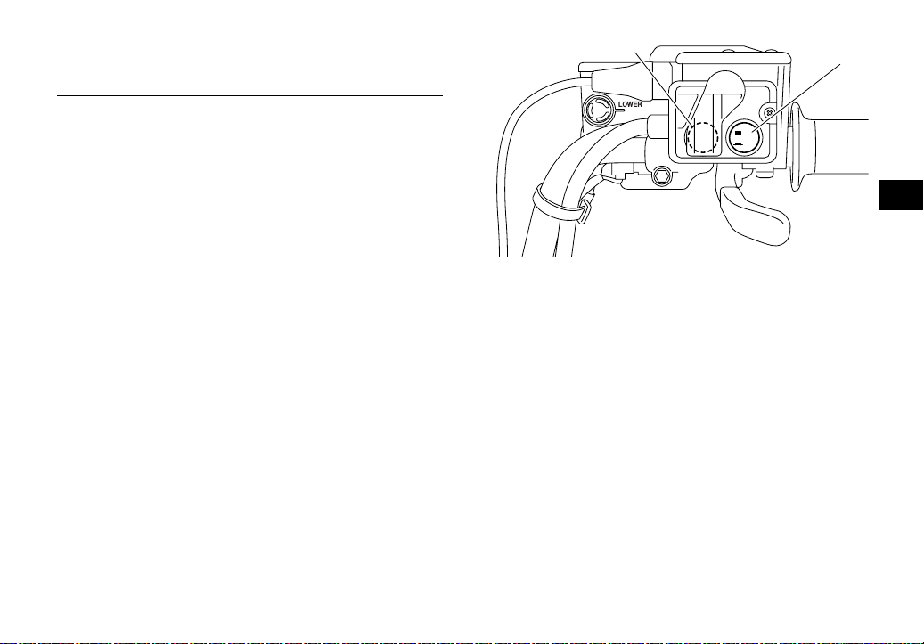
(a)
Stop the ATV, move the differential gear lock lever
to position (a), and then push the differential gear
lock switch in to the “LOCK” position. When the differential gear is locked, the differential gear lock indicator light “DIFF. LOCK” will come on along with
the indicator “” in the multi-function display.
LOCK
4WD
1. On-Command differential gear lock switch “4WD”/“LOCK”
To release the differential gear lock, stop the ATV
and push the switch to the “4WD” position.
TIP
● When the switch is set to “LOCK”, the differential
gear lock indicator and indicator light will flash
until the differential gear is locked.
● When the indicator and indicator light are flash-
ing, turning the handlebar back and forth will
help the differential gear lock to engage.
4-12
 Loading...