


EAS00010
FZ6-SS/FZ6-SSC
SERVICE MANUAL
2003 by Yamaha Motor
Corporation, U.S.A.
First edition, November 2003
All rights reserved. Any reproduction
or unauthorized use without the written
permission of Yamaha Motor Corporation,
U.S.A. is expressly prohibited.
Printed in U.S.A.
P/N LIT-11616-17-50

EAS00030
NOTICE
This manual was produced by the Yamaha Motor Company, Ltd. primarily for use by Yamaha dealers
and their qualified mechanics. It is not possible to include all the knowledge of a mechanic in one manual. Therefore, anyone who uses this book to perform maintenance and repairs on Yamaha vehicles
should have a basic understanding of mechanics and the techniques to repair these types of vehicles.
Repair and maintenance work attempted by anyone without this knowledge is likely to render the vehicle unsafe and unfit for use.
This model has been designed and manufactured to perform within certain specifications in regard to
performance and emissions. Proper service with the correct tools is necessary to ensure that the vehicle will operate as designed. If there is any question about a service procedure, it is imperative that
you contact a Yamaha dealer for any service information changes that apply to this model. This policy
is intended to provide the customer with the most satisfaction from his vehicle and to conform to federal
environmental quality objectives.
Yamaha Motor Company, Ltd. is continually striving to improve all of its models. Modifications and significant changes in specifications or procedures will be forwarded to all authorized Yamaha dealers
and will appear in future editions of this manual where applicable.
NOTE:
S This Service Manual contains information regarding periodic maintenance to the emission control
system. Please read this material carefully.
S Designs and specifications are subject to change without notice.
EAS00040
IMPORTANT MANUAL INFORMATION
Particularly important information is distinguished in this manual by the following.
The Safety Alert Symbol means ATTENTION! BECOME ALERT! YOUR
SAFETY IS INVOLVED!
WARNING
CAUTION:
NOTE: A NOTE provides key information to make procedures easier or clearer.
Failure to follow WARNING instructions could result in severe injury or death
the motorcycle operator, a bystander or a person checking or repairing the motorcycle.
A CAUTION indicates special precautions that must be taken to avoid damage
to the motorcycle.
to

EAS00007
HOW TO USE THIS MANUAL
This manual is intended as a handy, easy-to-read reference book for the mechanic. Comprehensive
explanations of all installation, removal, disassembly, assembly, repair and check procedures are laid
out with the individual steps in sequential order.
1
The manual is divided into chapters. An abbreviation and symbol in the upper right corner of each
page indicate the current chapter.
Refer to “SYMBOLS”.
2
Each chapter is divided into sections. The current section title is shown at the top of each page,
except in Chapter 3 (“PERIODIC CHECKS AND ADJUSTMENTS”), where the sub-section title(s) appears.
3
Sub-section titles appear in smaller print than the section title.
4
To help identify parts and clarify procedure steps, there are exploded diagrams at the start of each
removal and disassembly section.
5
Numbers are given in the order of the jobs in the exploded diagram. A circled number indicates a
disassembly step.
6
Symbols indicate parts to be lubricated or replaced.
Refer to “SYMBOLS”.
7
A job instruction chart accompanies the exploded diagram, providing the order of jobs, names of
parts, notes in jobs, etc.
8
Jobs requiring more information (such as special tools and technical data) are described sequentially.
4
5
6
7
12
3
8

1
GEN
INFO
3
CHK
ADJ
5
ENG
7
FI ELEC
2
SPEC
4
CHAS
6
COOL
8
EAS00008
SYMBOLS
The following symbols are not relevant to every
vehicle.
Symbols
chapter.
General information
1
Specifications
2
Periodic checks and adjustments
3
Chassis
4
Engine
5
Cooling system
6
Fuel injection system
7
Electrical system
8
Troubleshooting
9
1
to 9 indicate the subject of each
9
10
TRBL
SHTG
11 12
1413
16 1715
19 2018
22
24 25
Symbols 10 to 17 indicate the following.
10
Serviceable with engine mounted
11
Filling fluid
12
Lubricant
13
Special tool
14
Tightening torque
15
Wear limit, clearance
16
Engine speed
17
Electrical data
Symbols 18 to 23 in the exploded diagrams indicate the types of lubricants and lubrication
points.
18
Engine oil
19
Gear oil
20
2321
Molybdenum-disulfide oil
21
Wheel-bearing grease
22
Lithium-soap- based grease
23
Molybdenum-disulfide grease
Symbols 24 to 25 in the exploded diagrams indicate the following.
24
Apply locking agent (LOCTITE)
25
Replace the part

EAS00012
TABLE OF CONTENTS
GENERAL INFORMATION
SPECIFICATIONS
PERIODIC CHECKS AND
ADJUSTMENTS
CHASSIS
ENGINE
GEN
INFO
SPEC
CHK
ADJ
CHAS
ENG
1
2
3
4
5
COOLING SYSTEM
FUEL INJECTION SYSTEM
ELECTRICAL SYSTEM
TROUBLESHOOTING
COOL
FI
ELEC
TRBL
SHTG
6
7
8
9

CHAPTER 1
GENERAL INFORMATION
MOTORCYCLE IDENTIFICATION 1-1. . . . . . . . . . . . . . . . . . . . . . . . . . . . . .
VEHICLE IDENTIFICATION NUMBER 1-1. . . . . . . . . . . . . . . . . . . . . . . .
MODEL LABEL 1-1. . . . . . . . . . . . . . . . . . . . . . . . . . . . . . . . . . . . . . . . . . . .
FEATURES 1-2. . . . . . . . . . . . . . . . . . . . . . . . . . . . . . . . . . . . . . . . . . . . . . . . . .
OUTLINE OF FI SYSTEM 1-2. . . . . . . . . . . . . . . . . . . . . . . . . . . . . . . . . . .
FI SYSTEM 1-3. . . . . . . . . . . . . . . . . . . . . . . . . . . . . . . . . . . . . . . . . . . . . . .
INSTRUMENT FUNCTION 1-4. . . . . . . . . . . . . . . . . . . . . . . . . . . . . . . . . .
IMPORTANT INFORMATION 1-6. . . . . . . . . . . . . . . . . . . . . . . . . . . . . . . . . . .
PREPARATION FOR REMOVAL AND DISASSEMBLY 1-6. . . . . . . . .
REPLACEMENT PARTS 1-6. . . . . . . . . . . . . . . . . . . . . . . . . . . . . . . . . . . .
GASKETS, OIL SEALS AND O-RINGS 1-6. . . . . . . . . . . . . . . . . . . . . . .
LOCK WASHERS/PLATES AND COTTER PINS 1-7. . . . . . . . . . . . . .
BEARINGS AND OIL SEALS 1-7. . . . . . . . . . . . . . . . . . . . . . . . . . . . . . . .
CIRCLIPS 1-7. . . . . . . . . . . . . . . . . . . . . . . . . . . . . . . . . . . . . . . . . . . . . . . . .
CHECKING THE CONNECTIONS 1-8. . . . . . . . . . . . . . . . . . . . . . . . . . . . . . .
SPECIAL TOOLS 1-9. . . . . . . . . . . . . . . . . . . . . . . . . . . . . . . . . . . . . . . . . . . . .
CHAPTER 2
SPECIFICATIONS
GENERAL SPECIFICATIONS 2-1. . . . . . . . . . . . . . . . . . . . . . . . . . . . . . . . . .
ENGINE SPECIFICATIONS 2-2. . . . . . . . . . . . . . . . . . . . . . . . . . . . . . . . . . . .
CHASSIS SPECIFICATIONS 2-10. . . . . . . . . . . . . . . . . . . . . . . . . . . . . . . . . . .
ELECTRICAL SPECIFICATIONS 2-14. . . . . . . . . . . . . . . . . . . . . . . . . . . . . . .
CONVERSION TABLE 2-17. . . . . . . . . . . . . . . . . . . . . . . . . . . . . . . . . . . . . . . . .
GENERAL TIGHTENING TORQUE SPECIFICATIONS 2-17. . . . . . . . . . . .
TIGHTENING TORQUES 2-18. . . . . . . . . . . . . . . . . . . . . . . . . . . . . . . . . . . . . .
ENGINE TIGHTENING TORQUES 2-18. . . . . . . . . . . . . . . . . . . . . . . . . . .
CHASSIS TIGHTENING TORQUES 2-21. . . . . . . . . . . . . . . . . . . . . . . . . .
LUBRICATION POINTS AND LUBRICANT TYPES 2-23. . . . . . . . . . . . . . .
ENGINE 2-23. . . . . . . . . . . . . . . . . . . . . . . . . . . . . . . . . . . . . . . . . . . . . . . . . .
CHASSIS 2-24. . . . . . . . . . . . . . . . . . . . . . . . . . . . . . . . . . . . . . . . . . . . . . . . .
COOLING SYSTEM DIAGRAMS 2-25. . . . . . . . . . . . . . . . . . . . . . . . . . . . . . .

ENGINE OIL LUBRICATION CHART 2-29. . . . . . . . . . . . . . . . . . . . . . . . . . . .
LUBRICATION DIAGRAMS 2-30. . . . . . . . . . . . . . . . . . . . . . . . . . . . . . . . . . . .
CABLE ROUTING 2-36. . . . . . . . . . . . . . . . . . . . . . . . . . . . . . . . . . . . . . . . . . . .
CHAPTER 3
PERIODIC CHECKS AND ADJUSTMENTS
INTRODUCTION 3-1. . . . . . . . . . . . . . . . . . . . . . . . . . . . . . . . . . . . . . . . . . . . . .
PERIODIC MAINTENANCE CHART FOR THE EMISSION
CONTROL SYSTEM 3-1. . . . . . . . . . . . . . . . . . . . . . . . . . . . . . . . . . . . . . . . . .
GENERAL MAINTENANCE AND LUBRICATION CHART 3-1. . . . . . . . .
SEAT 3-3. . . . . . . . . . . . . . . . . . . . . . . . . . . . . . . . . . . . . . . . . . . . . . . . . . . . . . . .
FUEL TANK 3-4. . . . . . . . . . . . . . . . . . . . . . . . . . . . . . . . . . . . . . . . . . . . . . . . . .
REMOVING THE FUEL TANK 3-6. . . . . . . . . . . . . . . . . . . . . . . . . . . . . . .
REMOVING THE FUEL PUMP 3-6. . . . . . . . . . . . . . . . . . . . . . . . . . . . . .
INSTALLING THE FUEL PUMP 3-7. . . . . . . . . . . . . . . . . . . . . . . . . . . . . .
INSTALLING THE FUEL TANK 3-7. . . . . . . . . . . . . . . . . . . . . . . . . . . . . .
COWLINGS 3-8. . . . . . . . . . . . . . . . . . . . . . . . . . . . . . . . . . . . . . . . . . . . . . . . . .
AIR FILTER CASE 3-9. . . . . . . . . . . . . . . . . . . . . . . . . . . . . . . . . . . . . . . . . . . .
BATTERY BOX AND BATTERY BOX BRACKET 3-10. . . . . . . . . . . . . . . . .
ENGINE 3-11. . . . . . . . . . . . . . . . . . . . . . . . . . . . . . . . . . . . . . . . . . . . . . . . . . . . .
ADJUSTING THE VALVE CLEARANCE 3-11. . . . . . . . . . . . . . . . . . . . . .
SYNCHRONIZING THE THROTTLE BODIES 3-17. . . . . . . . . . . . . . . . .
ADJUSTING THE ENGINE IDLING SPEED 3-19. . . . . . . . . . . . . . . . . . .
ADJUSTING THE THROTTLE CABLE FREE PLAY 3-20. . . . . . . . . . . .
CHECKING THE SPARK PLUGS 3-23. . . . . . . . . . . . . . . . . . . . . . . . . . . .
MEASURING THE COMPRESSION PRESSURE 3-24. . . . . . . . . . . . . .
CHECKING THE ENGINE OIL LEVEL 3-27. . . . . . . . . . . . . . . . . . . . . . . .
CHANGING THE ENGINE OIL 3-28. . . . . . . . . . . . . . . . . . . . . . . . . . . . . .
MEASURING THE ENGINE OIL PRESSURE 3-30. . . . . . . . . . . . . . . . .
ADJUSTING THE CLUTCH CABLE FREE PLAY 3-32. . . . . . . . . . . . . . .
CLEANING THE AIR FILTER ELEMENT 3-33. . . . . . . . . . . . . . . . . . . . . .
CHECKING THE THROTTLE BODY JOINTS 3-34. . . . . . . . . . . . . . . . . .
CHECKING THE FUEL AND BREATHER HOSES 3-35. . . . . . . . . . . . .
CHECKING THE CRANKCASE BREATHER HOSE 3-35. . . . . . . . . . . .
CHECKING THE EXHAUST SYSTEM 3-36. . . . . . . . . . . . . . . . . . . . . . . .
CHECKING THE COOLANT LEVEL 3-37. . . . . . . . . . . . . . . . . . . . . . . . . .
CHECKING THE COOLING SYSTEM 3-38. . . . . . . . . . . . . . . . . . . . . . . .
CHANGING THE COOLANT 3-38. . . . . . . . . . . . . . . . . . . . . . . . . . . . . . . .

CHASSIS 3-42. . . . . . . . . . . . . . . . . . . . . . . . . . . . . . . . . . . . . . . . . . . . . . . . . . . .
ADJUSTING THE FRONT BRAKE 3-42. . . . . . . . . . . . . . . . . . . . . . . . . . .
ADJUSTING THE REAR BRAKE 3-43. . . . . . . . . . . . . . . . . . . . . . . . . . . .
CHECKING THE BRAKE FLUID LEVEL 3-44. . . . . . . . . . . . . . . . . . . . . .
CHECKING THE FRONT AND REAR BRAKE PADS 3-45. . . . . . . . . . .
ADJUSTING THE REAR BRAKE LIGHT SWITCH 3-46. . . . . . . . . . . . .
CHECKING THE FRONT AND REAR BRAKE HOSES 3-46. . . . . . . . .
BLEEDING THE HYDRAULIC BRAKE SYSTEM 3-47. . . . . . . . . . . . . . .
ADJUSTING THE SHIFT PEDAL 3-48. . . . . . . . . . . . . . . . . . . . . . . . . . . .
ADJUSTING THE DRIVE CHAIN SLACK 3-49. . . . . . . . . . . . . . . . . . . . .
LUBRICATING THE DRIVE CHAIN 3-50. . . . . . . . . . . . . . . . . . . . . . . . . .
CHECKING AND ADJUSTING THE STEERING HEAD 3-51. . . . . . . . .
CHECKING THE FRONT FORK 3-53. . . . . . . . . . . . . . . . . . . . . . . . . . . . .
ADJUSTING THE REAR SHOCK ABSORBER ASSEMBLY 3-54. . . . .
CHECKING THE TIRES 3-54. . . . . . . . . . . . . . . . . . . . . . . . . . . . . . . . . . . .
CHECKING THE WHEELS 3-57. . . . . . . . . . . . . . . . . . . . . . . . . . . . . . . . . .
CHECKING AND LUBRICATING THE CABLES 3-58. . . . . . . . . . . . . . .
LUBRICATING THE LEVERS AND PEDALS 3-58. . . . . . . . . . . . . . . . . .
LUBRICATING THE SIDESTAND 3-58. . . . . . . . . . . . . . . . . . . . . . . . . . . .
LUBRICATING THE CENTERSTAND 3-58. . . . . . . . . . . . . . . . . . . . . . . .
LUBRICATING THE REAR SUSPENSION 3-59. . . . . . . . . . . . . . . . . . . .
ELECTRICAL SYSTEM 3-60. . . . . . . . . . . . . . . . . . . . . . . . . . . . . . . . . . . . . . . .
CHECKING AND CHARGING THE BATTERY 3-60. . . . . . . . . . . . . . . . .
CHECKING THE FUSES 3-66. . . . . . . . . . . . . . . . . . . . . . . . . . . . . . . . . . .
REPLACING THE HEADLIGHT BULBS 3-68. . . . . . . . . . . . . . . . . . . . . .
ADJUSTING THE HEADLIGHT BEAMS 3-69. . . . . . . . . . . . . . . . . . . . . .
CHAPTER 4
CHASSIS
FRONT WHEEL AND BRAKE DISCS 4-1. . . . . . . . . . . . . . . . . . . . . . . . . . .
REMOVING THE FRONT WHEEL 4-3. . . . . . . . . . . . . . . . . . . . . . . . . . .
CHECKING THE FRONT WHEEL 4-3. . . . . . . . . . . . . . . . . . . . . . . . . . . .
CHECKING THE BRAKE DISCS 4-5. . . . . . . . . . . . . . . . . . . . . . . . . . . . .
INSTALLING THE FRONT WHEEL 4-6. . . . . . . . . . . . . . . . . . . . . . . . . . .
ADJUSTING THE FRONT WHEEL STATIC BALANCE 4-7. . . . . . . . .
REAR WHEEL AND BRAKE DISC 4-9. . . . . . . . . . . . . . . . . . . . . . . . . . . . . .
REAR WHEEL 4-9. . . . . . . . . . . . . . . . . . . . . . . . . . . . . . . . . . . . . . . . . . . . .
REAR BRAKE DISC AND REAR WHEEL SPROCKET 4-10. . . . . . . . .
REMOVING THE REAR WHEEL 4-12. . . . . . . . . . . . . . . . . . . . . . . . . . . . .
CHECKING THE REAR WHEEL 4-13. . . . . . . . . . . . . . . . . . . . . . . . . . . . .
CHECKING THE REAR WHEEL DRIVE HUB 4-13. . . . . . . . . . . . . . . . .
CHECKING AND REPLACING THE REAR WHEEL
SPROCKET 4-13. . . . . . . . . . . . . . . . . . . . . . . . . . . . . . . . . . . . . . . . . . . . . . .
INSTALLING THE REAR WHEEL 4-14. . . . . . . . . . . . . . . . . . . . . . . . . . . .
ADJUSTING THE REAR WHEEL STATIC BALANCE 4-15. . . . . . . . . . .

FRONT AND REAR BRAKES 4-16. . . . . . . . . . . . . . . . . . . . . . . . . . . . . . . . . .
FRONT BRAKE PADS 4-16. . . . . . . . . . . . . . . . . . . . . . . . . . . . . . . . . . . . . .
REAR BRAKE PADS 4-17. . . . . . . . . . . . . . . . . . . . . . . . . . . . . . . . . . . . . . .
REPLACING THE FRONT BRAKE PADS 4-19. . . . . . . . . . . . . . . . . . . . .
REPLACING THE REAR BRAKE PADS 4-21. . . . . . . . . . . . . . . . . . . . . .
FRONT BRAKE MASTER CYLINDER 4-23. . . . . . . . . . . . . . . . . . . . . . . .
REAR BRAKE MASTER CYLINDER 4-26. . . . . . . . . . . . . . . . . . . . . . . . .
DISASSEMBLING THE FRONT BRAKE MASTER CYLINDER 4-28. .
CHECKING THE FRONT AND REAR BRAKE MASTER
CYLINDERS 4-28. . . . . . . . . . . . . . . . . . . . . . . . . . . . . . . . . . . . . . . . . . . . . .
DISASSEMBLING THE REAR BRAKE MASTER CYLINDER 4-29. . . .
ASSEMBLING AND INSTALLING THE FRONT BRAKE
MASTER CYLINDER 4-30. . . . . . . . . . . . . . . . . . . . . . . . . . . . . . . . . . . . . . .
ASSEMBLING THE REAR BRAKE MASTER CYLINDER 4-32. . . . . . .
FRONT BRAKE CALIPERS 4-34. . . . . . . . . . . . . . . . . . . . . . . . . . . . . . . . .
REAR BRAKE CALIPER 4-36. . . . . . . . . . . . . . . . . . . . . . . . . . . . . . . . . . . .
DISASSEMBLING THE FRONT BRAKE CALIPERS 4-38. . . . . . . . . . .
DISASSEMBLING THE REAR BRAKE CALIPER 4-39. . . . . . . . . . . . . .
CHECKING THE FRONT AND REAR BRAKE CALIPERS 4-40. . . . . .
ASSEMBLING AND INSTALLING THE FRONT BRAKE
CALIPERS 4-41. . . . . . . . . . . . . . . . . . . . . . . . . . . . . . . . . . . . . . . . . . . . . . . .
ASSEMBLING AND INSTALLING THE REAR BRAKE
CALIPER 4-43. . . . . . . . . . . . . . . . . . . . . . . . . . . . . . . . . . . . . . . . . . . . . . . . .
FRONT FORK 4-45. . . . . . . . . . . . . . . . . . . . . . . . . . . . . . . . . . . . . . . . . . . . . . . .
FRONT FORK LEGS 4-45. . . . . . . . . . . . . . . . . . . . . . . . . . . . . . . . . . . . . . .
REMOVING THE FRONT FORK LEGS 4-48. . . . . . . . . . . . . . . . . . . . . . .
DISASSEMBLING THE FRONT FORK LEGS 4-48. . . . . . . . . . . . . . . . .
CHECKING THE FRONT FORK LEGS 4-50. . . . . . . . . . . . . . . . . . . . . . .
ASSEMBLING THE FRONT FORK LEGS 4-51. . . . . . . . . . . . . . . . . . . . .
INSTALLING THE FRONT FORK LEGS 4-54. . . . . . . . . . . . . . . . . . . . . .
HANDLEBAR 4-55. . . . . . . . . . . . . . . . . . . . . . . . . . . . . . . . . . . . . . . . . . . . . . . .
REMOVING THE HANDLEBAR 4-56. . . . . . . . . . . . . . . . . . . . . . . . . . . . . .
CHECKING THE HANDLEBAR 4-56. . . . . . . . . . . . . . . . . . . . . . . . . . . . . .
INSTALLING THE HANDLEBAR 4-57. . . . . . . . . . . . . . . . . . . . . . . . . . . . .
STEERING HEAD 4-59. . . . . . . . . . . . . . . . . . . . . . . . . . . . . . . . . . . . . . . . . . . . .
UNDER BRACKET 4-59. . . . . . . . . . . . . . . . . . . . . . . . . . . . . . . . . . . . . . . . .
REMOVING THE UNDER BRACKET 4-61. . . . . . . . . . . . . . . . . . . . . . . . .
CHECKING THE STEERING HEAD 4-61. . . . . . . . . . . . . . . . . . . . . . . . . .
INSTALLING THE STEERING HEAD 4-62. . . . . . . . . . . . . . . . . . . . . . . . .
REAR SHOCK ABSORBER ASSEMBLY 4-64. . . . . . . . . . . . . . . . . . . . . . . .
REMOVING THE REAR SHOCK ABSORBER ASSEMBLY 4-65. . . . .
HANDLING THE REAR SHOCK ABSORBER 4-66. . . . . . . . . . . . . . . . .
DISPOSING OF A REAR SHOCK ABSORBER 4-66. . . . . . . . . . . . . . . .
CHECKING THE REAR SHOCK ABSORBER ASSEMBLY 4-66. . . . . .
INSTALLING THE REAR SHOCK ABSORBER ASSEMBLY 4-67. . . . .

SWINGARM AND DRIVE CHAIN 4-68. . . . . . . . . . . . . . . . . . . . . . . . . . . . . . .
REMOVING THE SWINGARM 4-70. . . . . . . . . . . . . . . . . . . . . . . . . . . . . . .
REMOVING THE DRIVE CHAIN 4-71. . . . . . . . . . . . . . . . . . . . . . . . . . . . .
CHECKING THE SWINGARM 4-71. . . . . . . . . . . . . . . . . . . . . . . . . . . . . . .
INSTALLING THE SWINGARM 4-72. . . . . . . . . . . . . . . . . . . . . . . . . . . . . .
CHECKING THE DRIVE CHAIN 4-73. . . . . . . . . . . . . . . . . . . . . . . . . . . . .
CHAPTER 5
ENGINE
ENGINE 5-1. . . . . . . . . . . . . . . . . . . . . . . . . . . . . . . . . . . . . . . . . . . . . . . . . . . . .
DRIVE SPROCKET. 5-1. . . . . . . . . . . . . . . . . . . . . . . . . . . . . . . . . . . . . . . .
EXHAUST PIPE 5-2. . . . . . . . . . . . . . . . . . . . . . . . . . . . . . . . . . . . . . . . . . .
LEADS AND HOSES 5-3. . . . . . . . . . . . . . . . . . . . . . . . . . . . . . . . . . . . . . .
ENGINE 5-5. . . . . . . . . . . . . . . . . . . . . . . . . . . . . . . . . . . . . . . . . . . . . . . . . .
INSTALLING THE ENGINE 5-6. . . . . . . . . . . . . . . . . . . . . . . . . . . . . . . . .
CAMSHAFTS 5-8. . . . . . . . . . . . . . . . . . . . . . . . . . . . . . . . . . . . . . . . . . . . . . . . .
CYLINDER HEAD COVER 5-8. . . . . . . . . . . . . . . . . . . . . . . . . . . . . . . . . .
CAMSHAFTS 5-9. . . . . . . . . . . . . . . . . . . . . . . . . . . . . . . . . . . . . . . . . . . . .
REMOVING THE CAMSHAFTS 5-11. . . . . . . . . . . . . . . . . . . . . . . . . . . . .
CHECKING THE CAMSHAFTS 5-12. . . . . . . . . . . . . . . . . . . . . . . . . . . . . .
CHECKING THE TIMING CHAIN, CAMSHAFT SPROCKETS,
AND TIMING CHAIN GUIDES 5-14. . . . . . . . . . . . . . . . . . . . . . . . . . . . . . .
CHECKING THE TIMING CHAIN TENSIONER 5-14. . . . . . . . . . . . . . . .
INSTALLING THE CAMSHAFTS 5-15. . . . . . . . . . . . . . . . . . . . . . . . . . . . .
CYLINDER HEAD 5-19. . . . . . . . . . . . . . . . . . . . . . . . . . . . . . . . . . . . . . . . . . . . .
REMOVING THE CYLINDER HEAD 5-20. . . . . . . . . . . . . . . . . . . . . . . . . .
CHECKING THE CYLINDER HEAD 5-20. . . . . . . . . . . . . . . . . . . . . . . . . .
INSTALLING THE CYLINDER HEAD 5-21. . . . . . . . . . . . . . . . . . . . . . . . .
VALVES AND VALVE SPRINGS 5-22. . . . . . . . . . . . . . . . . . . . . . . . . . . . . . . .
REMOVING THE VALVES 5-24. . . . . . . . . . . . . . . . . . . . . . . . . . . . . . . . . .
CHECKING THE VALVES AND VALVE GUIDES 5-25. . . . . . . . . . . . . . .
CHECKING THE VALVE SEATS 5-27. . . . . . . . . . . . . . . . . . . . . . . . . . . . .
CHECKING THE VALVE SPRINGS 5-29. . . . . . . . . . . . . . . . . . . . . . . . . .
CHECKING THE VALVE LIFTERS 5-30. . . . . . . . . . . . . . . . . . . . . . . . . . .
INSTALLING THE VALVES 5-30. . . . . . . . . . . . . . . . . . . . . . . . . . . . . . . . .
STARTER CLUTCH AND GENERATOR 5-32. . . . . . . . . . . . . . . . . . . . . . . . .
STATOR COIL ASSEMBLY 5-32. . . . . . . . . . . . . . . . . . . . . . . . . . . . . . . . .
REMOVING THE GENERATOR 5-34. . . . . . . . . . . . . . . . . . . . . . . . . . . . .
REMOVING THE STARTER CLUTCH 5-35. . . . . . . . . . . . . . . . . . . . . . . .
CHECKING THE STARTER CLUTCH 5-36. . . . . . . . . . . . . . . . . . . . . . . .
INSTALLING THE STARTER CLUTCH 5-36. . . . . . . . . . . . . . . . . . . . . . .
INSTALLING THE GENERATOR 5-37. . . . . . . . . . . . . . . . . . . . . . . . . . . . .

SHIFT SHAFT 5-39. . . . . . . . . . . . . . . . . . . . . . . . . . . . . . . . . . . . . . . . . . . . . . . .
SHIFT SHAFT AND STOPPER LEVER 5-39. . . . . . . . . . . . . . . . . . . . . . .
CHECKING THE SHIFT SHAFT 5-41. . . . . . . . . . . . . . . . . . . . . . . . . . . . .
CHECKING THE STOPPER LEVER 5-41. . . . . . . . . . . . . . . . . . . . . . . . .
INSTALLING THE SHIFT SHAFT 5-41. . . . . . . . . . . . . . . . . . . . . . . . . . . .
CRANKSHAFT POSITION SENSOR AND PICKUP ROTOR 5-42. . . . . . .
REMOVING THE PICKUP ROTOR 5-44. . . . . . . . . . . . . . . . . . . . . . . . . . .
INSTALLING THE PICKUP ROTOR 5-44. . . . . . . . . . . . . . . . . . . . . . . . . .
CLUTCH 5-46. . . . . . . . . . . . . . . . . . . . . . . . . . . . . . . . . . . . . . . . . . . . . . . . . . . . .
CLUTCH COVER 5-46. . . . . . . . . . . . . . . . . . . . . . . . . . . . . . . . . . . . . . . . . .
CLUTCH 5-48. . . . . . . . . . . . . . . . . . . . . . . . . . . . . . . . . . . . . . . . . . . . . . . . . .
REMOVING THE CLUTCH 5-49. . . . . . . . . . . . . . . . . . . . . . . . . . . . . . . . . .
CHECKING THE FRICTION PLATES 5-49. . . . . . . . . . . . . . . . . . . . . . . . .
CHECKING THE CLUTCH PLATES 5-50. . . . . . . . . . . . . . . . . . . . . . . . . .
CHECKING THE CLUTCH SPRINGS 5-50. . . . . . . . . . . . . . . . . . . . . . . .
CHECKING THE CLUTCH HOUSING 5-51. . . . . . . . . . . . . . . . . . . . . . . .
CHECKING THE CLUTCH BOSS 5-51. . . . . . . . . . . . . . . . . . . . . . . . . . . .
CHECKING THE PRESSURE PLATE 5-51. . . . . . . . . . . . . . . . . . . . . . . .
CHECKING THE PULL LEVER SHAFT AND PULL ROD 5-52. . . . . . .
INSTALLING THE CLUTCH 5-52. . . . . . . . . . . . . . . . . . . . . . . . . . . . . . . . .
OIL PAN AND OIL PUMP 5-55. . . . . . . . . . . . . . . . . . . . . . . . . . . . . . . . . . . . . .
REMOVING THE OIL PAN 5-58. . . . . . . . . . . . . . . . . . . . . . . . . . . . . . . . . .
CHECKING THE OIL PUMP 5-58. . . . . . . . . . . . . . . . . . . . . . . . . . . . . . . . .
CHECKING THE RELIEF VALVE 5-59. . . . . . . . . . . . . . . . . . . . . . . . . . . .
CHECKING THE OIL DELIVERY PIPE AND OIL PIPE 5-59. . . . . . . . .
CHECKING THE OIL STRAINER 5-59. . . . . . . . . . . . . . . . . . . . . . . . . . . .
CHECKING THE OIL NOZZLES 5-59. . . . . . . . . . . . . . . . . . . . . . . . . . . . .
ASSEMBLING THE OIL PUMP 5-60. . . . . . . . . . . . . . . . . . . . . . . . . . . . . .
INSTALLING THE OIL PUMP 5-60. . . . . . . . . . . . . . . . . . . . . . . . . . . . . . .
INSTALLING THE OIL STRAINER 5-61. . . . . . . . . . . . . . . . . . . . . . . . . . .
INSTALLING THE OIL PAN 5-61. . . . . . . . . . . . . . . . . . . . . . . . . . . . . . . . .
CRANKCASE 5-62. . . . . . . . . . . . . . . . . . . . . . . . . . . . . . . . . . . . . . . . . . . . . . . .
DISASSEMBLING THE CRANKCASE 5-64. . . . . . . . . . . . . . . . . . . . . . . .
CHECKING THE CRANKCASE 5-65. . . . . . . . . . . . . . . . . . . . . . . . . . . . . .
CHECKING THE BEARINGS AND OIL SEALS 5-65. . . . . . . . . . . . . . . .
CHECKING THE TIMING CHAIN 5-65. . . . . . . . . . . . . . . . . . . . . . . . . . . .
ASSEMBLING THE CRANKCASE 5-65. . . . . . . . . . . . . . . . . . . . . . . . . . .

CONNECTING RODS AND PISTONS 5-67. . . . . . . . . . . . . . . . . . . . . . . . . . .
REMOVING THE CONNECTING RODS AND PISTONS 5-68. . . . . . . .
REMOVING THE CRANKSHAFT ASSEMBLY 5-69. . . . . . . . . . . . . . . . .
CHECKING THE CYLINDER AND PISTON 5-69. . . . . . . . . . . . . . . . . . .
CHECKING THE PISTON RINGS 5-70. . . . . . . . . . . . . . . . . . . . . . . . . . . .
CHECKING THE PISTON PINS 5-71. . . . . . . . . . . . . . . . . . . . . . . . . . . . .
CHECKING THE BIG END BEARINGS 5-72. . . . . . . . . . . . . . . . . . . . . . .
INSTALLING THE CONNECTING ROD AND PISTON
(except for CAL) 5-76. . . . . . . . . . . . . . . . . . . . . . . . . . . . . . . . . . . . . . . . . . .
INSTALLING THE CONNECTING ROD AND PISTON
(for CAL) 5-79. . . . . . . . . . . . . . . . . . . . . . . . . . . . . . . . . . . . . . . . . . . . . . . . . .
CRANKSHAFT 5-83. . . . . . . . . . . . . . . . . . . . . . . . . . . . . . . . . . . . . . . . . . . . . . .
CHECKING THE CRANKSHAFT 5-84. . . . . . . . . . . . . . . . . . . . . . . . . . . . .
CHECKING THE CRANKSHAFT JOURNAL BEARINGS 5-84. . . . . . . .
INSTALLING THE CRANKSHAFT 5-87. . . . . . . . . . . . . . . . . . . . . . . . . . . .
TRANSMISSION 5-88. . . . . . . . . . . . . . . . . . . . . . . . . . . . . . . . . . . . . . . . . . . . . .
TRANSMISSION, SHIFT DRUM ASSEMBLY AND SHIFT
FORKS 5-88. . . . . . . . . . . . . . . . . . . . . . . . . . . . . . . . . . . . . . . . . . . . . . . . . . .
REMOVING THE TRANSMISSION 5-94. . . . . . . . . . . . . . . . . . . . . . . . . . .
CHECKING THE SHIFT FORKS 5-94. . . . . . . . . . . . . . . . . . . . . . . . . . . . .
CHECKING THE SHIFT DRUM ASSEMBLY 5-95. . . . . . . . . . . . . . . . . . .
CHECKING THE TRANSMISSION 5-95. . . . . . . . . . . . . . . . . . . . . . . . . . .
INSTALLING THE TRANSMISSION 5-96. . . . . . . . . . . . . . . . . . . . . . . . . .
CHAPTER 6
COOLING SYSTEM
RADIATOR 6-1. . . . . . . . . . . . . . . . . . . . . . . . . . . . . . . . . . . . . . . . . . . . . . . . . . .
CHECKING THE RADIATOR 6-3. . . . . . . . . . . . . . . . . . . . . . . . . . . . . . . .
INSTALLING THE RADIATOR 6-4. . . . . . . . . . . . . . . . . . . . . . . . . . . . . . .
OIL COOLER 6-5. . . . . . . . . . . . . . . . . . . . . . . . . . . . . . . . . . . . . . . . . . . . . . . . .
CHECKING THE OIL COOLER 6-7. . . . . . . . . . . . . . . . . . . . . . . . . . . . . .
INSTALLING THE OIL COOLER 6-7. . . . . . . . . . . . . . . . . . . . . . . . . . . . .
THERMOSTAT 6-8. . . . . . . . . . . . . . . . . . . . . . . . . . . . . . . . . . . . . . . . . . . . . . .
CHECKING THE THERMOSTAT 6-9. . . . . . . . . . . . . . . . . . . . . . . . . . . . .
INSTALLING THE THERMOSTAT 6-10. . . . . . . . . . . . . . . . . . . . . . . . . . . .
WATER PUMP 6-11. . . . . . . . . . . . . . . . . . . . . . . . . . . . . . . . . . . . . . . . . . . . . . . .
DISASSEMBLING THE WATER PUMP 6-13. . . . . . . . . . . . . . . . . . . . . . .
CHECKING THE WATER PUMP 6-14. . . . . . . . . . . . . . . . . . . . . . . . . . . . .
ASSEMBLING THE WATER PUMP 6-14. . . . . . . . . . . . . . . . . . . . . . . . . .
INSTALLING THE WATER PUMP 6-16. . . . . . . . . . . . . . . . . . . . . . . . . . . .

CHAPTER 7
FUEL INJECTION SYSTEM
FUEL INJECTION SYSTEM 7-1. . . . . . . . . . . . . . . . . . . . . . . . . . . . . . . . . . . .
WIRING DIAGRAM 7-2. . . . . . . . . . . . . . . . . . . . . . . . . . . . . . . . . . . . . . . .
ECU’S SELF-DIAGNOSTIC FUNCTION 7-3. . . . . . . . . . . . . . . . . . . . . .
ALTERNATE INSTRUCTIONS OPERATION CONTROL
(FAIL-SAFE ACTION) 7-4. . . . . . . . . . . . . . . . . . . . . . . . . . . . . . . . . . . . . .
FAIL-SAFE ACTIONS TABLE 7-4. . . . . . . . . . . . . . . . . . . . . . . . . . . . . . .
TROUBLESHOOTING CHART 7-6. . . . . . . . . . . . . . . . . . . . . . . . . . . . . .
DIAGNOSTIC MODE 7-7. . . . . . . . . . . . . . . . . . . . . . . . . . . . . . . . . . . . . . .
TROUBLESHOOTING DETAILS 7-13. . . . . . . . . . . . . . . . . . . . . . . . . . . . .
THROTTLE BODIES 7-25. . . . . . . . . . . . . . . . . . . . . . . . . . . . . . . . . . . . . . . . . .
INJECTORS 7-27. . . . . . . . . . . . . . . . . . . . . . . . . . . . . . . . . . . . . . . . . . . . . . .
CHECKING THE INJECTORS 7-28. . . . . . . . . . . . . . . . . . . . . . . . . . . . . . .
CHECKING THE THROTTLE BODIES 7-28. . . . . . . . . . . . . . . . . . . . . . .
CHECKING THE FUEL PUMP AND PRESSURE REGULATOR
OPERATION 7-29. . . . . . . . . . . . . . . . . . . . . . . . . . . . . . . . . . . . . . . . . . . . . .
CHECKING AND ADJUSTING THE THROTTLE POSITION
SENSOR 7-30. . . . . . . . . . . . . . . . . . . . . . . . . . . . . . . . . . . . . . . . . . . . . . . . .
AIR INDUCTION SYSTEM 7-32. . . . . . . . . . . . . . . . . . . . . . . . . . . . . . . . . . . . .
AIR INJECTION 7-32. . . . . . . . . . . . . . . . . . . . . . . . . . . . . . . . . . . . . . . . . . .
AIR CUT-OFF VALVE 7-32. . . . . . . . . . . . . . . . . . . . . . . . . . . . . . . . . . . . . .
AIR INDUCTION SYSTEM DIAGRAMS 7-33. . . . . . . . . . . . . . . . . . . . . . .
CHECKING THE AIR INDUCTION SYSTEM 7-34. . . . . . . . . . . . . . . . . .
CHAPTER 8
ELECTRICAL SYSTEM
ELECTRICAL COMPONENTS 8-1. . . . . . . . . . . . . . . . . . . . . . . . . . . . . . . . . .
CHECKING SWITCH CONTINUITY 8-3. . . . . . . . . . . . . . . . . . . . . . . . . . . . .
CHECKING THE SWITCHES 8-4. . . . . . . . . . . . . . . . . . . . . . . . . . . . . . . . . . .
CHECKING THE BULBS AND BULB SOCKETS 8-5. . . . . . . . . . . . . . . . .
TYPES OF BULBS 8-5. . . . . . . . . . . . . . . . . . . . . . . . . . . . . . . . . . . . . . . . .
CHECKING THE CONDITION OF THE BULBS 8-5. . . . . . . . . . . . . . . .
CHECKING THE CONDITION OF THE BULB SOCKETS 8-6. . . . . . .
CHECKING THE LED’s 8-7. . . . . . . . . . . . . . . . . . . . . . . . . . . . . . . . . . . . .
IGNITION SYSTEM 8-8. . . . . . . . . . . . . . . . . . . . . . . . . . . . . . . . . . . . . . . . . . .
CIRCUIT DIAGRAM 8-8. . . . . . . . . . . . . . . . . . . . . . . . . . . . . . . . . . . . . . . .
TROUBLESHOOTING 8-9. . . . . . . . . . . . . . . . . . . . . . . . . . . . . . . . . . . . . .

ELECTRIC STARTING SYSTEM 8-14. . . . . . . . . . . . . . . . . . . . . . . . . . . . . . . .
CIRCUIT DIAGRAM 8-14. . . . . . . . . . . . . . . . . . . . . . . . . . . . . . . . . . . . . . . .
STARTING CIRCUIT CUT-OFF SYSTEM OPERATION 8-15. . . . . . . . .
TROUBLESHOOTING 8-16. . . . . . . . . . . . . . . . . . . . . . . . . . . . . . . . . . . . . .
STARTER MOTOR 8-19. . . . . . . . . . . . . . . . . . . . . . . . . . . . . . . . . . . . . . . . . . . .
CHECKING THE STARTER MOTOR 8-21. . . . . . . . . . . . . . . . . . . . . . . . .
ASSEMBLING THE STARTER MOTOR 8-22. . . . . . . . . . . . . . . . . . . . . .
CHARGING SYSTEM 8-24. . . . . . . . . . . . . . . . . . . . . . . . . . . . . . . . . . . . . . . . .
CIRCUIT DIAGRAM 8-24. . . . . . . . . . . . . . . . . . . . . . . . . . . . . . . . . . . . . . . .
TROUBLESHOOTING 8-25. . . . . . . . . . . . . . . . . . . . . . . . . . . . . . . . . . . . . .
LIGHTING SYSTEM 8-27. . . . . . . . . . . . . . . . . . . . . . . . . . . . . . . . . . . . . . . . . . .
CIRCUIT DIAGRAM 8-27. . . . . . . . . . . . . . . . . . . . . . . . . . . . . . . . . . . . . . . .
TROUBLESHOOTING 8-29. . . . . . . . . . . . . . . . . . . . . . . . . . . . . . . . . . . . . .
CHECKING THE LIGHTING SYSTEM 8-31. . . . . . . . . . . . . . . . . . . . . . . .
SIGNALING SYSTEM 8-34. . . . . . . . . . . . . . . . . . . . . . . . . . . . . . . . . . . . . . . . .
CIRCUIT DIAGRAM 8-34. . . . . . . . . . . . . . . . . . . . . . . . . . . . . . . . . . . . . . . .
TROUBLESHOOTING 8-36. . . . . . . . . . . . . . . . . . . . . . . . . . . . . . . . . . . . . .
CHECKING THE SIGNALING SYSTEM 8-36. . . . . . . . . . . . . . . . . . . . . .
COOLING SYSTEM 8-43. . . . . . . . . . . . . . . . . . . . . . . . . . . . . . . . . . . . . . . . . . .
CIRCUIT DIAGRAM 8-43. . . . . . . . . . . . . . . . . . . . . . . . . . . . . . . . . . . . . . . .
TROUBLESHOOTING 8-44. . . . . . . . . . . . . . . . . . . . . . . . . . . . . . . . . . . . . .
FUEL PUMP SYSTEM 8-47. . . . . . . . . . . . . . . . . . . . . . . . . . . . . . . . . . . . . . . . .
CIRCUIT DIAGRAM 8-47. . . . . . . . . . . . . . . . . . . . . . . . . . . . . . . . . . . . . . . .
FUEL PUMP SYSTEM 8-48. . . . . . . . . . . . . . . . . . . . . . . . . . . . . . . . . . . . . .
TROUBLESHOOTING 8-49. . . . . . . . . . . . . . . . . . . . . . . . . . . . . . . . . . . . . .
CHECKING THE FUEL PUMP 8-51. . . . . . . . . . . . . . . . . . . . . . . . . . . . . . .
SELF-DIAGNOSIS 8-52. . . . . . . . . . . . . . . . . . . . . . . . . . . . . . . . . . . . . . . . . . . .
TROUBLESHOOTING 8-53. . . . . . . . . . . . . . . . . . . . . . . . . . . . . . . . . . . . . .
CHAPTER 9
TROUBLESHOOTING
STARTING FAILURES 9-1. . . . . . . . . . . . . . . . . . . . . . . . . . . . . . . . . . . . . . . . .
ENGINE 9-1. . . . . . . . . . . . . . . . . . . . . . . . . . . . . . . . . . . . . . . . . . . . . . . . . .
FUEL SYSTEM 9-1. . . . . . . . . . . . . . . . . . . . . . . . . . . . . . . . . . . . . . . . . . . .
ELECTRICAL SYSTEMS 9-1. . . . . . . . . . . . . . . . . . . . . . . . . . . . . . . . . . .
INCORRECT ENGINE IDLING SPEED 9-2. . . . . . . . . . . . . . . . . . . . . . . . . .
ENGINE 9-2. . . . . . . . . . . . . . . . . . . . . . . . . . . . . . . . . . . . . . . . . . . . . . . . . .
FUEL SYSTEM 9-2. . . . . . . . . . . . . . . . . . . . . . . . . . . . . . . . . . . . . . . . . . . .
ELECTRICAL SYSTEMS 9-2. . . . . . . . . . . . . . . . . . . . . . . . . . . . . . . . . . .

POOR MEDIUM-AND-HIGH-SPEED PERFORMANCE 9-2. . . . . . . . . . . .
ENGINE 9-2. . . . . . . . . . . . . . . . . . . . . . . . . . . . . . . . . . . . . . . . . . . . . . . . . .
FUEL SYSTEM 9-2. . . . . . . . . . . . . . . . . . . . . . . . . . . . . . . . . . . . . . . . . . . .
FAULTY GEAR SHIFTING 9-3. . . . . . . . . . . . . . . . . . . . . . . . . . . . . . . . . . . . .
SHIFTING IS DIFFICULT 9-3. . . . . . . . . . . . . . . . . . . . . . . . . . . . . . . . . . .
SHIFT PEDAL DOES NOT MOVE 9-3. . . . . . . . . . . . . . . . . . . . . . . . . . .
JUMPS OUT OF GEAR 9-3. . . . . . . . . . . . . . . . . . . . . . . . . . . . . . . . . . . . .
FAULTY CLUTCH 9-3. . . . . . . . . . . . . . . . . . . . . . . . . . . . . . . . . . . . . . . . . . . . .
CLUTCH SLIPS 9-3. . . . . . . . . . . . . . . . . . . . . . . . . . . . . . . . . . . . . . . . . . .
CLUTCH DRAGS 9-3. . . . . . . . . . . . . . . . . . . . . . . . . . . . . . . . . . . . . . . . . .
OVERHEATING 9-4. . . . . . . . . . . . . . . . . . . . . . . . . . . . . . . . . . . . . . . . . . . . . . .
ENGINE 9-4. . . . . . . . . . . . . . . . . . . . . . . . . . . . . . . . . . . . . . . . . . . . . . . . . .
COOLING SYSTEM 9-4. . . . . . . . . . . . . . . . . . . . . . . . . . . . . . . . . . . . . . . .
FUEL SYSTEM 9-4. . . . . . . . . . . . . . . . . . . . . . . . . . . . . . . . . . . . . . . . . . . .
CHASSIS 9-4. . . . . . . . . . . . . . . . . . . . . . . . . . . . . . . . . . . . . . . . . . . . . . . . .
ELECTRICAL SYSTEMS 9-4. . . . . . . . . . . . . . . . . . . . . . . . . . . . . . . . . . .
OVERCOOLING 9-4. . . . . . . . . . . . . . . . . . . . . . . . . . . . . . . . . . . . . . . . . . . . . .
COOLING SYSTEM 9-4. . . . . . . . . . . . . . . . . . . . . . . . . . . . . . . . . . . . . . . .
POOR BRAKING PERFORMANCE 9-4. . . . . . . . . . . . . . . . . . . . . . . . . . . . .
FAULTY FRONT FORK LEGS 9-5. . . . . . . . . . . . . . . . . . . . . . . . . . . . . . . . . .
LEAKING OIL 9-5. . . . . . . . . . . . . . . . . . . . . . . . . . . . . . . . . . . . . . . . . . . . .
MALFUNCTION 9-5. . . . . . . . . . . . . . . . . . . . . . . . . . . . . . . . . . . . . . . . . . .
UNSTABLE HANDLING 9-5. . . . . . . . . . . . . . . . . . . . . . . . . . . . . . . . . . . . . . .
FAULTY LIGHTING OR SIGNALING SYSTEM 9-6. . . . . . . . . . . . . . . . . . .
HEADLIGHT DOES NOT COME ON 9-6. . . . . . . . . . . . . . . . . . . . . . . . .
HEADLIGHT BULB BURNT OUT 9-6. . . . . . . . . . . . . . . . . . . . . . . . . . . .
TAIL/BRAKE LIGHT DOES NOT COME ON 9-6. . . . . . . . . . . . . . . . . .
TAIL/BRAKE LIGHT BULB BURNT OUT 9-6. . . . . . . . . . . . . . . . . . . . .
TURN SIGNAL DOES NOT COME ON 9-6. . . . . . . . . . . . . . . . . . . . . . .
TURN SIGNAL BLINKS SLOWLY 9-6. . . . . . . . . . . . . . . . . . . . . . . . . . . .
TURN SIGNAL REMAINS LIT 9-6. . . . . . . . . . . . . . . . . . . . . . . . . . . . . . .
TURN SIGNAL BLINKS QUICKLY 9-6. . . . . . . . . . . . . . . . . . . . . . . . . . .
HORN DOES NOT SOUND 9-6. . . . . . . . . . . . . . . . . . . . . . . . . . . . . . . . .

MOTORCYCLE IDENTIFICATION
EAS00014
GENERAL INFORMATION
MOTORCYCLE IDENTIFICATION
EAS00017
VEHICLE IDENTIFICATION NUMBER
The vehicle identification number
into the right side of the steering head pipe.
EAS00018
MODEL LABEL
1
The model label
information will be needed to order spare parts.
is affixed to the frame. This
GEN
INFO
1
is stamped
1
1-1

GEN
FEATURES
EAS00896
FEATURES
OUTLINE OF FI SYSTEM
The main function of a fuel supply system is to provide fuel to the combustion chamber at the optimum
air-fuel ratio in accordance with the engine operating conditions and the atmospheric temperature.
In the conventional carburetor system, the air-fuel ratio of the mixture that is supplied to the combustion
chamber is created by the volume of the intake air and the fuel that is metered by the jet used in the
respective carburetor.
Despite the same volume of intake air, the fuel volume requirement varies by the engine operating
conditions, such as acceleration, deceleration, or operating under a heavy load. Carburetors that meter the fuel through the use of jets have been provided with various auxiliary devices, so that an optimum air-fuel ratio can be achieved to accommodate the constant changes in the operating conditions
of the engine.
As the requirements for the engine to deliver more performance and cleaner exhaust gases increase, it
becomes necessary to control the air-fuel ratio in a more precise and finely tuned manner. To accommodate this need, this model has adopted an electronically controlled fuel injection (FI) system, in
place of the conventional carburetor system. This system can achieve an optimum air-fuel ratio required by the engine at all times by using a microprocessor that regulates the fuel injection volume
according to the engine operating conditions detected by various sensors.
The adoption of the FI system has resulted in a highly precise fuel supply, improved engine response,
better fuel economy, and reduced exhaust emissions. Furthermore, the air induction system (AI system) has been placed under computer control together with the FI system in order to realize cleaner
exhaust gases.
INFO
1 Ignition coil
2 Air filter case
3 Intake air temperature
sensor
4 Fuel delivery hose
5 Fuel tank
6 Fuel pump
7 Intake air pressure
sensor
8 Throttle position sen-
sor
9 Fuel injector
10 Catalytic converter
11 Crankshaft position
sensor
12 Coolant temperature
sensor
13 Spark plug
14 Pressure regulator
15 Battery
16 ECU
17 Fuel injection system
relay
1-2
18 Engine trouble warn-
ing light
19 Lean angle cut-off
switch

GEN
FEATURES
EAS00897
FI SYSTEM
The fuel pump delivers fuel to the injector via the fuel filter. The pressure regulator maintains the fuel
pressure that is applied to the injector at only 250 kPa (2.5 kg/cm
signal from the ECU energizes the injector, the fuel passage opens, causing the fuel to be injected into
the intake manifold only during the time the passage remains open. Therefore, the longer the length of
time the injector is energized (injection duration), the greater the volume of fuel that is supplied. Conversely, the shorter the length of time the injector is energized (injection duration), the lesser the volume of fuel that is supplied.
The injection duration and the injection timing are controlled by the ECU. Signals that are input from the
throttle position sensor, crankshaft position sensor, intake air pressure sensor, intake temperature
sensor and coolant temperature sensor enable the ECU to determine the injection duration. The injection timing is determined through the signals from the crankshaft position sensor. As a result, the volume of fuel that is required by the engine can be supplied at all times in accordance with the driving
conditions.
Illustration is for reference only.
2
). Accordingly, when the energizing
INFO
1 Fuel pump
2 Pressure regulator
3 Fuel injector
4 Throttle body
5 Intake air temperature
sensor
6 Throttle position sen-
sor
7 Intake air pressure
sensor
8 ECU
9 Coolant temperature
sensor
10 Crankshaft position
sensor
1-3
A Fuel system
B Control system

1 Multi-function display
2 “SELECT” button
3 “RESET” button
4 Engine trouble warning light
GEN
FEATURES
INSTRUMENT FUNCTION
Multi-function display
The multi-function display is equipped with the
following:
S a speedometer (which shows the riding
speed)
S an odometer (which shows the total distance
traveled)
S two tripmeters (which show the distance
traveled since they were last set to zero)
S a fuel reserve tripmeter (which shows the
distance traveled since the bottom segment
of the fuel meter started flashing)
S a tachometer (which shows the engine
speed)
S a fuel meter
S a water temperature
S a clock
S a intake air temperature
S a self-diagnosis device
INFO
NOTE:
S Be sure to turn the key to “ON” before using the “SELECT” and ”RESET” buttons.
S For the U.K. only: To switch the speedometer and odometer/tripmeter display between kilometers
and miles, press the “SELECT” button for at least two seconds.
Odometer, tripmeter and tachometer modes
Pushing the “SELECT” button switches the display between the odometer mode “ODO” and the tripmeter modes “TRIP 1” and “TRIP 2” and the tachometer mode “E” is the following order:
ODO ! TRIP 1 ! TRIP 2 ! (TRIP F) ! E ! ODO
When approximately 3.6 L of fuel remain in the fuel tank, the bottom segment of the fuel meter will start
flashing, and the odometer display will automatically change to the fuel reserve tripmeter mode “TRIP
F” and start counting the distance traveled from that point. In that case, pushing the “SELECT” button
switches the display between the various tripmeter and odometer modes in the following order:
TRIP-F ! E ! ODO ! TRIP 1 ! TRIP 2 ! TRIP F
To reset a tripmeter, select it by pushing the “SELECT” button, and then push the “RESET” button for at
least one second. If you do not reset the fuel reserve tripmeter manually, it will reset itself automatically
and the display will return to the prior mode after refueling and traveling 5 km (3.1 mi).
Tachometer mode
Displays the digital indication of the engine speed on the odometer section.
Air intake temperature indicator.
When “ODO” is displayed, pressing the “RESET” for a long time allows the indicator to switch displays
between Clock and Air intake temperature. (It activates the clock indication when the main switch is
turned OFF.)
In the Co adjustment mode, the indication automatically changes from clock (Air intake temperature) to
the engine speed.
1-4

GEN
FEATURES
Clock mode
To set the clock:
1. Push the “SELECT” button and “RESET” button together for at least two seconds.
2. When the hour digits start flashing, push the “RESET” button to set the hours.
3. Push the “SELECT” button, and the minute digits will start flashing.
4. Push the “RESET” button to set the minutes.
5. Push the “SELECT” button and then release it to start the clock.
INFO
1-5

IMPORTANT INFORMATION
EAS00020
IMPORTANT INFORMATION
PREPARATION FOR REMOVAL AND
DISASSEMBLY
1. Before removal and disassembly, eliminate
all dirt, mud, dust and foreign material.
2. Use only the proper tools and cleaning
equipment.
Refer to the “SPECIAL TOOLS”.
3. When disassembling, always keep mated
parts together. This includes gears, cylinders, pistons and other parts that have been
“mated” through normal wear. Mated parts
must always be reused or replaced as an assembly.
4. During disassembly, clean all of the parts
and place them in trays in the order of disassembly. This will speed up assembly and allow for the correct installation of all parts.
5. Keep all parts away from any source of fire.
GEN
INFO
lip
oil
lip
spring
grease
EAS00021
REPLACEMENT PARTS
Use only genuine Yamaha parts for all replacements. Use oil and grease recommended by
Yamaha for all lubrication jobs. Other brands
may be similar in function and appearance, but
inferior in quality.
EAS00022
GASKETS, OIL SEALS AND O-RINGS
1. When overhauling the engine, replace all
gaskets, seals and O-rings. All gasket surfaces, oil seal lips and O-rings must be
cleaned.
2. During reassembly, properly oil all mating
parts and bearings and lubricate the oil seal
lips with grease.
1-6

IMPORTANT INFORMATION
EAS00023
LOCK WASHERS/ PLATES AND COTTER
PINS
After removal, replace all lock washers/plates
1
and cotter pins. After the bolt or nut has been
tightened to specification, bend the lock tabs
along a flat of the bolt or nut.
EAS00024
BEARINGS AND OIL SEALS
Install bearings and oil seals so that the
manufacturer’s marks or numbers are visible.
When installing oil seals, lubricate the oil seal
lips with a light coat of lithium-soap-based
grease. Oil bearings liberally when installing, if
appropriate.
Oil seal
1
GEN
INFO
CAUTION:
Do not spin the bearing with compressed air
because this will damage the bearing surfaces.
Bearing
1
EAS00025
CIRCLIPS
Before reassembly, check all circlips carefully
and replace damaged or distorted circlips. Always replace piston pin clips after one use.
When installing a circlip
sharp-edged corner
3
the thrust
Shaft
4
that the circlip receives.
1
, make sure the
2
is positioned opposite
1-7

CHECKING THE CONNECTIONS
EAS00026
CHECKING THE CONNECTIONS
Check the leads, couplers, and connectors for
stains, rust, moisture, etc.
1. Disconnect:
S lead
S coupler
S connector
2. Check:
S lead
S coupler
S connector
Moisture ! Dry with an air blower.
Rust/stains ! Connect and disconnect sev-
eral times.
3. Check:
S all connections
Loose connection ! Connect properly.
NOTE:
If the pin
up.
1
on the terminal is flattened, bend it
GEN
INFO
4. Connect:
S lead
S coupler
S connector
NOTE:
Make sure all connections are tight.
5. Check:
S continuity
(with the pocket tester)
Pocket tester
90890-03112, YU-3112
NOTE:
S If there is no continuity, clean the terminals.
S When checking the wire harness, perform
steps (1) to (3).
S As a quick remedy, use a contact revitalizer
available at most part stores.
1-8

GEN
SPECIAL TOOLS
EAS00027
SPECIAL TOOLS
The following special tools are necessary for complete and accurate tune-up and assembly. Use only
the appropriate special tools as this will help prevent damage caused by the use of inappropriate tools
or improvised techniques. Special tools, part numbers or both may differ depending on the country.
When placing an order, refer to the list provided below to avoid any mistakes.
NOTE:
S For U.S.A. and Canada, use part number starting with “YM-”, “YU-”, or “ACC-”.
S For others, use part number starting with “90890-”.
INFO
Tool No.
Flywheel puller
90890-01362
YU-33270-B
Adapter
90890-04089
YM-33282
90890-01701
YS-01880-A
90890-01304
YU-01304
Radiator cap
tester
90890-01325
YU-24460-01
Adapter
90890-01352
YU-33984
Tool name / Function Illustration
Flywheel puller
Adapter
This tool is used to remove the generator rotor.
Sheave holder
This tool is used to hold the generator rotor
when removing or installing the generator rotor bolt or pickup coil rotor bolt.
Piston pin puller
This tool is used to remove the piston pins.
Radiator cap tester
Adapter
These tools are used to check the cooling
system.
90890-01403
YU-33975
90890-01460
-01326
Pivot shaft
wrench
90890-01471
YM-01471
Pivot shaft wrench
adapter
90890-01476
Steering nut wrench
This tool is used to loosen or tighten the steering stem ring nuts.
Damper rod holder
T-handle
2
1
These tool are used for holding the damper
rod when removing or installing the damper
rod.
Pivot shaft wrench
Pivot shaft wrench adapter
This tool is used to loosen or tighten the pivot
adjust bolt and engine mount adjust bolt.
1-9
1

SPECIAL TOOLS
Tool No. Tool name / Function Illustration
Oil filter wrench
90890-01426
YU-38411
Fork seal driver
90890-01367
YM-33963
Fork seal driver
attachment
90890-01374
YM-8020-A
Vacuum gauge
90890-03094
YU-08030
Compression
gauge
90890-03081
YU-33223
Adapter
90890-04136
This tool is needed to loosen or tighten the oil
filter cartridge.
Fork seal driver weight
Fork seal driver attachment
This tool is used to install the front fork’s oil
seal and dust seal.
Vacuum gauge
This gauge is used to synchronize the carburetors.
Compression gauge
Adapter
These tools are used to measure engine
compression.
Pocket tester
GEN
INFO
90890-03112
YU-3112
Oil pressure
gauge
90890-03153
YU-03153
Adapter
90890-03139
90890-03176
YM-03176
90890-03153
YU-03153
90890-04044
YM-04044
Valve spring
compressor
90890-04019
YM-04019
Attachment
90890-04108
YM-01253
This tool is used to check the electrical system.
Oil pressure gauge
Adapter
These tools are used to measure engine oil
pressure.
Fuel pressure adapter
This tool is needed to measure fuel pressure.
Pressure gauge
This tool used is to measure fuel pressure.
Piston ring compressor
This tool is used to compress piston rings
when installing the cylinder.
Valve spring compressor
Attachment
These tools are used to remove or install the
valve assemblies.
1-10

SPECIAL TOOLS
Tool No. Tool name / Function Illustration
Middle driven shaft
bearing driver
90890-04058
YM-4058
Mechanical seal
installer
90890-04078
YM-33221
Middle driven shaft bearing driver
Mechanical seal installer
These tools are used to install the water pump
seal.
Clutch holding tool
GEN
INFO
90890-04086
YM-91042
90890-04101
90890-04111
90890-04112
90890-04113
YM-04113
This tool is used to hold the clutch boss
when removing or installing the clutch boss
nut.
Valve lapper
This tool is needed to remove and install
the valve lifter.
Valve guide remover (φ4)
This tool is used to remove or install the valve
guides.
Valve guide installer (φ4)
This tool is used to install the valve guides.
Valve guide reamer (φ4)
This tool is used to rebore the new valve
guides.
Ignition checker
90890-06754
YM-34487
90890-06756
YB-35956
90890-85505
ACC-1100105-01
This tool is used to check the ignition system
components.
Vacuum/pressure pump gauge set
This tool used to measure the vacuum pressure.
Yamaha bond No. 1215
This bond is used to seal two mating surfaces
(e.g., crankcase mating surfaces).
1-11

SPECIFICATIONS
GENERAL SPECIFICATIONS
Item Standard Limit
GENERAL SPECIFICATIONS
SPEC
Model code 5VX3 (USA except for CAL)
5VX4 (CAL)
Dimensions
Overall length
Overall width
Overall height
Seat height
Wheelbase
Minimum ground clearance
Minimum turning radius
Weight
Wet (with oil and a full fuel tank)
Maximum load (except motorcycle)
2,095 mm (82.5 in)
750 mm (29.5 in)
1,215 mm (47.8 in)
795 mm (31.3 in)
1,440 mm (56.7 in)
145 mm (5.71 in)
2,800 mm (110.2 in)
207 kg (456 lb) (USA except for CAL)
208 kg (459 lb) (CAL)
190 kg (419 lb) (USA except for CAL)
189 kg (417 lb) (CAL)
SSS
SSS
SSS
SSS
SSS
SSS
SSS
SSS
SSS
SSS
2-1

ENGINE SPECIFICATIONS
Item Standard Limit
Engine
Engine type
Displacement
Cylinder arrangement
Bore stroke
Compression ratio
Engine idling speed
Vacuum pressure at engine idling
speed
Standard compression pressure
(at sea level)
Fuel
Recommended fuel
Fuel tank capacity
Total (including reserve)
Reserve only
Engine oil
Lubrication system
Recommended oil
ENGINE SPECIFICATIONS
Liquid-cooled, 4-stroke, DOHC
600 cm
Forward-inclined parallel 4-cylinder
65.5 44.5 mm (2.58 1.75 in)
12.2 : 1
1,250 X 1,350 r/min
29 kPa (218 mmHg, 8.6 inHg)
1,550 kPa (15.50 kg/cm
220.46 psi) at 400 r/min
Unleaded gasoline only
19.4 L (4.25 lmp gal, 5.1 US gal)
3.6 L (0.79 lmp gal, 0.9 US gal)
Wet sump
3
(36.61 cu.in)
2
,15.50 bar,
SPEC
SSS
SSS
SSS
SSS
SSS
SSS
SSS
SSS
2
SSS
SSS
SSS
SSS
Quantity
Total amount
Without oil filter cartridge
replacement
With oil filter cartridge replacement
Oil pressure
Engine oil temperature
Relief valve opening pressure
At 5_C (40_F) or higher
Yamalube 4 (20W40) or SAE 20W40
type SE motor oil
At 15_C (60_F) or lower
Yamalube 4 (10W30) or SAE 10W30
type SE motor oil
3.4 L (2.99 Imp qt, 3.59 US qt)
2.5 L (2.20 lmp qt, 2.64 US qt)
2.8 L (2.47 lmp qt, 2.96 US qt)
240 kPa at 6,600 r/min
(2.4 kg/cm
(2.4 bar at 6,600 r/min)
(34.1 psi at 6,600 r/min)
96_C (205_F)
450 X 550 kPa (4.5 X 5.5 kg/cm
4.5 X 5.5 bar, 65.3 X 79.8 psi)
2
at 6,600 r/min)
2
SSS
SSS
SSS
SSS
SSS
SSS
SSS
SSS
SSS
,
2-2

ENGINE SPECIFICATIONS
Item Standard Limit
Oil filter
Oil filter type
Bypass valve opening pressure
Oil pump
Oil pump type
Inner-rotor-to-outer-rotor-tip
clearance
Outer-rotor-to-oil-pump-housing
clearance
Cooling system
Radiator capacity
Radiator cap opening pressure
Radiator core
Width
Height
Depth
Coolant reservoir
Capacity
Water pump
Water pump type
Reduction ratio
Max. impeller shaft tilt
Starting system type Electric starter
Formed
80 X 120 kPa (0.8 X 1.2 kg/cm
0.8 X 1.2 bar, 11.6 X 17.4 psi)
Trochoid
0.03 X 0.09 mm
(0.0012 X 0.0035 in)
0.03 X 0.08 mm
(0.0012 X 0.0032 in)
2.0 L (1.76 lmp pt, 2.11 US qt)
93.3 X 122.7 kPa (0.93 X 1.23 kg/cm
0.93 X 1.23 bar, 13.5 X 17.8 psi)
300 mm (11.81 in)
188 mm (7.4 in)
24 mm (0.94 in)
0.27 L (0.24 lmp qt, 0.29 US qt)
Single suction centrifugal pump
86/44 31/31 (1.955)
SSS
2
,
SPEC
SSS
SSS
SSS
0.15 mm
(0.0059 in)
0.15 mm
(0.0059 in)
2
,
SSS
SSS
SSS
SSS
SSS
SSS
SSS
0.15 mm
(0.006 in)
Spark plugs
Model (manufacturer) quantity
Spark plug gap
Cylinder head
Volume
Max. warpage
CR9EK (NGK) 4
0.6 X 0.7 mm (0.0236 X 0.0276 in)
10.3 X 10.9 cm3 (0.63 X 0.67 cu.in)
SSS
SSS
SSS
SSS
0.05 mm
(0.002 in)
2-3

Item Standard Limit
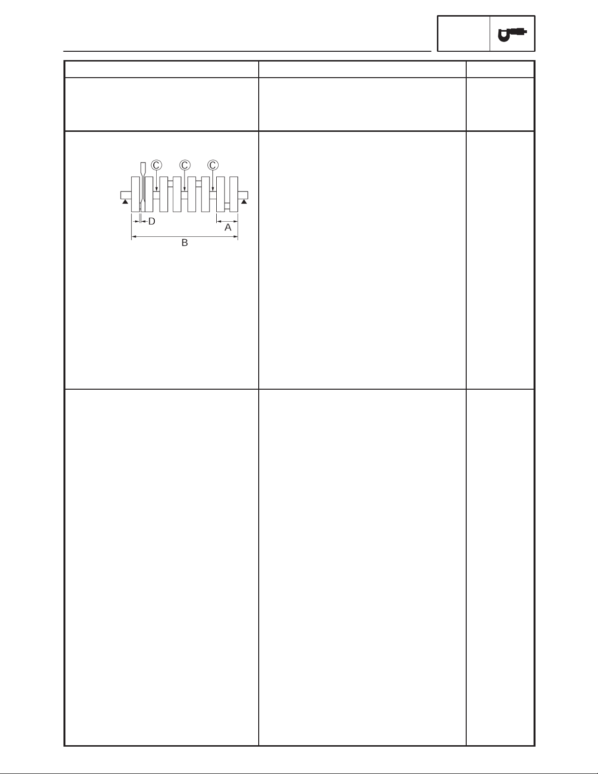
Camshafts
Drive system
Camshaft cap inside diameter
Camshaft journal diameter
Camshaft-journal-to-camshaftcap clearance
Intake camshaft lobe dimensions
ENGINE SPECIFICATIONS
Chain drive (right)
23.008 X 23.029 mm (0.9058 X 0.9067 in)
22.967 X 22.980 mm (0.9042 X 0.9047 in)
0.028 X 0.062 mm (0.0011 X 0.0024 in)
SPEC
SSS
SSS
SSS
0.08 mm
(0.0032 in)
Measurement A
Measurement B
Exhaust camshaft lobe dimensions
Measurement A
Measurement B
Max. camshaft runout
32.45 X 32.55 mm (1.278 X 1.282 in)
24.95 X 25.05 mm (0.982 X 0.986 in)
32.45 X 32.55 mm (1.278 X 1.282 in)
24.95 X 25.05 mm (0.982 X 0.986 in)
SSS
32.40 mm
(1,276 in)
24.90 mm
(0.980 in)
32.40 mm
(1.276 in)
24.90 mm
(0.980 in)
0.06 mm
(0.0024 in)
2-4

ENGINE SPECIFICATIONS
SPEC
Item Standard Limit
Timing chain
Model/number of links
Tensioning system
Valves, valve seats, valve guides
Valve clearance (cold)
Intake
Exhaust
Valve dimensions
Head Diameter Face Width Seat Width Margin Thickness
Valve head diameter A
Intake
Exhaust
Valve face width B
Intake
Exhaust
Valve seat width C
Intake
Exhaust
Valve margin thickness D
Intake
Exhaust
Valve stem diameter
Intake
Exhaust
Valve guide inside diameter
Intake
Exhaust
Valve-stem-to-valve-guide clearance
Intake
Exhaust
Valve stem runout
92RH2015/120
Automatic
0.13 X 0.20 mm (0.0051 X 0.0079 in)
0.23 X 0.30 mm (0.0091 X 0.0118 in)
24.9 X 25.1 mm (0.9803 X 0.9882 in)
21.9 X 22.1 mm (0.8622 X 0.8701 in)
1.14 X 1.98 mm (0.0449 X 0.0780 in)
1.14 X 1.98 mm (0.0449 X 0.0780 in)
0.9 X 1.1 mm (0.0354 X 0.0433 in)
0.9 X 1.1 mm (0.0354 X 0.0433 in)
0.6 X 0.8 mm (0.0236 X 0.0315 in)
0.6 X 0.8 mm (0.0236 X 0.0315 in)
3.975 X 3.990 mm (0.1565 X 0.1571 in)
3.960 X 3.975 mm (0.1559 X 0.1565 in)
4.000 X 4.012 mm (0.1575 X 0.1580 in)
4.000 X 4.012 mm (0.1575 X 0.1580 in)
0.010 X 0.037 mm (0.0004 X 0.0015 in)
0.025 X 0.052 mm (0.0010 X 0.0020 in)
SSS
SSS
SSS
SSS
SSS
SSS
SSS
SSS
SSS
1.6 mm (0.06 in)
1.6 mm (0.06 in)
0.5 mm (0.02 in)
0.5 mm (0.02 in)
3.95 mm
(0.1555 in)
3.935 mm
(0.1549 in)
4.042 mm
(0.1591 in)
4.042 mm
(0.1591 in)
0.08 mm
(0.0032 in)
0.10 mm
(0.0039 in)
0.04 mm
(0.0016 in)
Valve seat width
Intake
Exhaust
0.9 X 1.1 mm (0.0354 X 0.0433 in)
0.9 X 1.1 mm (0.0354 X 0.0433 in)
2-5
1.6 mm (0.06 in)
1.6 mm (0.06 in)

Item Standard Limit
Valve springs
Free length
Intake (inner)
Intake (outer)
Exhaust
Installed length (valve closed)
Intake (inner)
Intake (outer)
Exhaust
Compressed spring force
(installed)
Intake (inner)
(outer)
Exhaust
Spring tilt
ENGINE SPECIFICATIONS
37.0 mm (1.46 in)
38.4 mm (1.51 in)
41.8 mm (1.65 in)
30 mm (1.18 in)
32.5 mm (1.28 in)
36.1 mm (1.42 in)
69.0 X 79.0 N (7.03 X 8.05 kg,
15.50 X 17.75 lb)
114.0 X 132.0 N (11.62 X 13.46 kg,
25.63 X 29.67 lb)
160 X 184 N (16.32 X 18.76 kg,
35.97 X 41.36 lb)
SPEC
35.2 mm (1.39 in)
36.5 mm (1.44 in)
39.7 mm (1.56 in)
SSS
SSS
SSS
SSS
SSS
SSS
Intake (inner)
Intake (outer)
Exhaust
Winding direction (top view)
Intake (inner)
Intake (outer)
Exhaust
Cylinders
Cylinder arrangement
Bore stroke
Compression ratio
Bore
Max. out-of-round
SSS
SSS
SSS
Counter clockwise
Clockwise
Clockwise
Forward-inclined, parallel 4-cylinder
65.5 mm 44.5 mm (2.58 1.75 in)
12.2 : 1
65.50 X 65.51 mm (2.5787 X 2.5791 in)
SSS
2.5_/1.6 mm
(0.06 in)
2.5_ /1.7 mm
(0.07 in)
2.5_/1.8 mm
(0.07 in)
SSS
SSS
SSS
SSS
SSS
SSS
SSS
0.05 mm
(0.002 in)
2-6

Item Standard Limit
Piston
Piston-to-cylinder clearance
Diameter D
ENGINE SPECIFICATIONS
0.010 X 0.035 mm (0.0004 X 0.0014 in)
65.475 X 65.490 mm (2.5778 X 2.5783 in)
SPEC
0.055 mm
(0.0022 in)
SSS
Height H
Piston pin bore (in the piston)
Diameter
Offset
Offset direction
Piston pins
Outside diameter
Piston-pin-to-piston-pin-bore
clearance
Piston rings
Top ring
Ring type
Dimensions (B T)
End gap (installed)
Ring side clearance
2nd ring
4 mm (0.16 in)
16.002 X 16.013 mm
(0.6300 X 0.6304 in)
0.5 mm (0.0197 in)
Intake side
15.991 X 16.000 mm
(0.6296 X 0.6299 in)
0.002 X 0.022 mm (0.0001 X 0.0009 in)
Barrel
0.90 2.45 mm (0.04 0.10 in)
0.25 X 0.35 mm (0.0098 X 0.0138 in)
0.030 X 0.065 mm (0.0012 X 0.0026 in)
SSS
16.043 mm
(0.6316 in)
SSS
SSS
15.971 mm
(0.6288 in)
0.072 mm
(0.0028 in)
SSS
SSS
0.60 mm
(0.0236 in)
0.115 mm
(0.0045 in)
Ring type
Dimensions (B T)
End gap (installed)
Ring side clearance
Oil ring
Dimensions (B T)
End gap (installed)
Taper
0.8 2.5 mm (0.03 0.10 in)
0.7 X 0.8 mm (0.0276 X 0.0315 in)
0.030 X 0.065 mm (0.0012 X 0.0026 in)
1.5 2.0 mm (0.06 0.08 in)
0.10 X 0.35 mm (0.0039 X 0.0138 in)
2-7
SSS
SSS
1.15 mm
(0.0453 in)
0.125 mm
(0.0049 in)
SSS
SSS
Item Standard Limit
Connecting rods
Crankshaft-pin-to-big-end-bearing
clearance
Bearing color code
Crankshaft
ENGINE SPECIFICATIONS
0.028 X 0.052 mm (0.0011 X 0.0020 in)
1 = Blue 2 = Black 3 = Brown 4 = Green
SPEC
0.08 mm
(0.0032 in)
SSS
Width A
Width B
Max. runout C
Big end side clearance D
Big end radial clearance
Small end free play
Crankshaft-journal-to-crankshaftjournal-bearing clearance
Bearing color code
Clutch
Clutch type
Clutch release method
Clutch release method operation
Operation
Clutch cable free play (at the end
of the clutch lever)
Friction plates
Color code
Thickness
Plate quantity
Color code
Thickness
Plate quantity
Clutch plates
Thickness
Plate quantity
Max. warpage
Thickness
Plate quantity
Max. warpage
Clutch springs
Free length
Spring quantity
51.85 X 52.55 mm (2.04 X 2.06 in)
268.8 X 270.0 mm (10.58 X 10.63 in)
SSS
0.160 X 0.262 mm (0.0063 X 0.0103 in)
0.028 X 0.052 mm (0.0011 X 0.0020 in)
0.32 X 0.50 mm (0.01 X 0.02 in)
0.034 X 0.058 mm (0.0013 X 0.0023 in)
0 = White 1 = Black 2 = Brown
3 = Green 4 = Yellow
Wet, multiple disc
Outer pull, rack and pinion pull
Cable operation
Left-hand operation
10 X 15 mm (0.39 X 0.59 in)
Brown
2.9 X 3.1 mm (0.114 X 0.122 in)
6
Purple
2.9 X 3.1 mm (0.114 X 0.112 in)
2
1.9 X 2.1 mm (0.07 X 0.08 in)
7
SSS
2.2 X 2.4 mm (0.086 X 0.095 in)
1
SSS
55 mm (2.17 in)
6
SSS
SSS
0.03 mm
(0.0012 in)
SSS
SSS
SSS
0.10 mm
(0.0039 in)
SSS
SSS
SSS
SSS
SSS
SSS
SSS
2.8 mm
(0.110 in)
SSS
SSS
2.8 mm
(0.110 in)
SSS
SSS
SSS
0.1 mm
(0.0039 in)
SSS
SSS
0.1 mm
(0.0039 in)
52.3 mm
(2.06 in)
SSS
2-8

Item Standard Limit
Transmission
Transmission type
Primary reduction system
Primary reduction ratio
Secondary reduction system
Secondary reduction ratio
Operation
Gear ratios
1st gear
2nd gear
3rd gear
4th gear
5th gear
6th gear
Max. main axle runout
Max. drive axle runout
Shifting mechanism
Shift mechanism type
Max. shift fork guide bar bending
ENGINE SPECIFICATIONS
Constant mesh, 6-speed
Spur gear
86/44 (1.955)
Chain drive
46/16 (2.875)
Left-foot operation
37/13 (2.846)
37/19 (1.947)
28/18 (1.556)
32/24 (1.333)
25/21 (1.190)
26/24 (1.083)
SSS
SSS
Shift drum/Guide bar
SSS
SPEC
SSS
SSS
SSS
SSS
SSS
SSS
SSS
SSS
SSS
SSS
SSS
SSS
0.02 mm
(0.0008 in)
0.02 mm
(0.0008 in)
SSS
0.05 mm
(0.002 in)
Air filter type Oil-coated paper element SSS
Fuel pump
Pump type
Model (manufacturer)
Output pressure
Throttle position sensor
Resistance
Output voltage (at idle)
Throttle bodies
Model (manufacturer) quantity
Intake vacuum pressure
Throttle cable free play (at the flange
of the throttle grip)
ID mark
Throttle valve size
Electrical
5VX (DENSO)
250 kPa (2.5 kg/cm
4.0 X 6.0 kΩ at 20_C (68_F)
0.63 X 0.73 V (Adjusted by tachometer)
36EIDW (MIKUNI) 2
29 kPa (218 mmHg, 8.5038 inHg)
3 X 5 mm (0.12 X 0.20 in)
5VX1 00 (5VX3)
5VX4 10 (5VX4)
#50
2
, 2.5 bar, 36.3 psi)
SSS
SSS
SSS
SSS
SSS
SSS
SSS
SSS
SSS
2-9

CHASSIS SPECIFICATIONS
Item Standard Limit
Frame
Frame type
Caster angle
Trail
Front wheel
Wheel type
Rim
Size
Material
Wheel travel
Wheel runout
Max. radial wheel runout
Max. lateral wheel runout
Rear wheel
Wheel type
Rim
Size
Material
Wheel travel
Wheel runout
Max. radial wheel runout
Max. lateral wheel runout
CHASSIS SPECIFICATIONS
Diamond
25_
97.5 mm (3.84 in)
Cast wheel
17 M/C MT3.50
Aluminum
130 mm (5.12 in)
SSS
SSS
Cast wheel
17 M/C MT5.50
Aluminum
130 mm (5.12 in)
SSS
SSS
SPEC
SSS
SSS
SSS
SSS
SSS
SSS
SSS
1 mm (0.04 in)
0.5 mm (0.02 in)
SSS
SSS
SSS
SSS
1 mm (0.04 in)
0.5 mm (0.02 in)
Front tire
Tire type
Size
Model (manufacturer)
Tire pressure (cold)
0 X 90 kg (0 X 198 lb)
90 X 190 kg (198 X 419 lb)
90 X 189 kg (198 X 417 lb)
High-speed riding
Min. tire tread depth
Tubeless
120/70 ZR17 M/C (58W)
BT020F GG (BRIDGESTONE)
D252F (DUNLOP)
225 kPa (2.25 kgf/cm
250 kPa (2.5 kgf/cm
(except for CAL)
250 kPa (2.5 kgf/cm
(CAL)
225 kPa (2.25 kgf/cm
SSS
2
, 2.25 bar, 33 psi)
2
, 2.5 bar, 35.6 psi)
2
, 2.5 bar, 35.6 psi)
2
, 2.25 bar, 33 psi)
SSS
SSS
SSS
SSS
SSS
SSS
SSS
1.6 mm (0.06 in)
2-10

Item Standard Limit
Rear tire
Tire type
Size
Model (manufacturer)
Tire pressure (cold)
0 X 90 kg (0 X 198 lb)
90 X 190 kg (198 X 419 lb)
90 X 189 kg (198 X 417 lb)
High-speed riding
Min. tire tread depth
Front brakes
Brake type
Operation
Recommended fluid
Brake discs
Diameter thickness
Min. thickness
Max. deflection
Brake pad lining thickness
CHASSIS SPECIFICATIONS
Tubeless
180/55 ZR17 M/C (73W)
BT020R GG (BRIDGESTONE)
D252 (DUNLOP)
250 kPa (2.5 kgf/cm
290 kPa (2.9 kgf/cm
(except for CAL)
290 kPa (2.9 kgf/cm
(CAL)
250 kPa (2.5 kgf/cm
SSS
Dual disc brake
Right hand operation
DOT 4
298 5 mm (11.73 0.20 in)
SSS
SSS
6.0 mm (0.24 in)
2
, 2.5 bar, 35.6 psi)
2
, 2.9 bar, 41.3 psi)
2
, 2.9 bar, 41.3 psi)
2
, 2.5 bar, 35.6 psi)
SPEC
SSS
SSS
SSS
SSS
SSS
SSS
SSS
1.6 mm
(0.06 in)
SSS
SSS
SSS
SSS
4.5 mm
(0.18 in)
0.1 mm
(0.004 in)
0.8 mm
(0.03 in)
Master cylinder inside diameter
Caliper cylinder inside diameter
Rear brake
Brake type
Operation
Brake pedal position (below the
bottom of the footrest bracket)
Recommended fluid
Brake discs
Diameter thickness
Min. thickness
Max. deflection
Brake pad lining thickness
Master cylinder inside diameter
Caliper cylinder inside diameter
16 mm (0.63 in)
30.2 mm and 25.4 mm (1.19 in and 1.00 in)
Single disc brake
Right foot operation
25.8 mm (1.02 in)
DOT 4
245 5 mm (9.65 0.20 in)
SSS
SSS
6.0 mm (0.24 in)
12.7 mm (0.5 in)
38.1 mm (1.5 in)
SSS
SSS
SSS
SSS
SSS
SSS
SSS
4.5 mm
(0.18 in)
0.15 mm
(0.006 in)
1.0 mm
(0.04 in)
SSS
SSS
2-11
Item Standard Limit
Front suspension
Suspension type
Front fork type
Front fork travel
Spring
Free length
Spacer length
Installed length
Spring rate (K1)
Spring rate (K2)
Spring stroke (K1)
Spring stroke (K2)
Inner tube outer diameter
Inner tube bending limit
Optional spring available
Fork oil
Recommended oil
Quantity (each front fork leg)
Level (from the top of the inner
tube, with the inner tube fully
compressed, and without the
fork spring)
CHASSIS SPECIFICATIONS
Telescopic fork
Coil spring/oil damper
130 mm (5.12 in)
354.0 mm (13.94 in)
131.5 mm (5.18 in)
347.0 mm (13.66 in)
7.4 N/mm (0.75 kg/mm, 42.25 lb/in)
11.8 N/mm (1,20 kg/mm, 67.38 lb/in)
0 X 70 mm (0 X 2.76 in)
70 X 130 mm (2.76 X 5.12 in)
43 mm (1.69 in)
SSS
No
Suspension oil “01” or equivalent
0.467 L (0.41 lmp qt, 0.49 US qt)
134 mm (5.28 in)
SPEC
SSS
SSS
SSS
347 mm
(13.66 in)
SSS
SSS
SSS
SSS
SSS
SSS
SSS
0.2 mm
(0.01 in)
SSS
SSS
SSS
SSS
2-12

Item Standard Limit
Steering
Steering bearing type
Rear suspension
Suspension type
Rear shock absorber assembly
type
Rear shock absorber assembly
travel
Spring
Free length
Installed length
Spring rate (K1)
Spring stroke (K1)
Optional spring available
Standard spring preload gas/air
pressure
Spring preload adjusting positions
Minimum
Standard
Maximum
CHASSIS SPECIFICATIONS
Angular bearing SSS
Swingarm (monocross)
Coil spring/gas-oil damper
50 mm (1.97 in)
185.0 mm (7.28 in)
172.0 mm (6.77 in)
127.4 N/mm (12.99 kg/mm, 727.45 lb/in)
0 X 50 mm (0.00 X 1.97 in)
No
1,200 kPa (12 kg/cm
1
3
7
2
, 12 bar, 170.7 psi)
SPEC
SSS
SSS
SSS
SSS
SSS
SSS
SSS
SSS
SSS
SSS
SSS
SSS
Swingarm
Free play (at the end of the
swingarm)
Radial
Axial
Drive chain
Model (manufacturer)
Link quantity
Drive chain slack
Maximum ten-link section
SSS
SSS
50V4 (DAIDO)
118
45 X 55 mm (1.77 X 2.17 in)
SSS
1.0 mm
(0.04 in)
1.0 mm
(0.04 in)
SSS
SSS
SSS
150.1 mm
(5.91 in)
2-13

ELECTRICAL SPECIFICATIONS
()
()
SPEC
ELECTRICAL SPECIFICATIONS
Item Standard Limit
System voltage 12 V SSS
Ignition system
Ignition system type
Ignition timing
Advancer type
Crankshaft position sensor
resistance/color
T.C.I. unit model (manufacturer)
Ignition coils
Model (manufacturer)
Minimum ignition spark gap
Primary coil resistance
Secondary coil resistance
Spark plug cap
Material
Resistance
DC. T.C.I.
5_ BTDC at 1,300 r/min
Digital
248 X 372 Ω at 20_C (68_F)/Gy-B
F8T811 (MITSUBISHI)
JO383 (DENSO)
6 mm (0.24 in)
1.53 X 2.07 Ω at 20_C (68_F)
12.0 X 18.0 kΩ at 20_C (68_F)
Resin
10.0 kΩ at 20_C (68_F)
SSS
SSS
SSS
SSS
SSS
SSS
SSS
SSS
SSS
SSS
SSS
Charging system
System type
Model (manufacturer)
Normal output
Stator coil resistance/color
Rectifier/regulator
Regulator type
Model (manufacture)
No-load regulated voltage
Rectifier capacity
Withstand voltage
Battery
Battery type
Battery voltage/capacity
Specific gravity
Manufacturer
Ten hour rate amperage
Headlight type Halogen bulb
Bulbs (voltage/wattage quantity)
Headlight
Tail / brake light
Front turn signal/position light
Rear turn signal light
Licence light
Meter light
A.C. magneto
F5VX (MORIC)
14 V/310 W at 5,000 r/min
0.22 X 0.34 Ω at 20_C (68_F)/W-W
Semi conductor short circuit
SH719AA (SHINDENGEN)
14.1 X 14.9 V
18 A
240 V
GT12B-4
12 V/10 Ah
1.320
GS
1.0 A
12V 60 W/55 W 1
12 V 55 W 1
12 V 5 W/21 W 1
12 V 21 W/5 W 2
12 V 21 W 2
12 V 5 W 1
EL
SSS
SSS
SSS
SSS
SSS
SSS
SSS
SSS
SSS
SSS
SSS
SSS
SSS
SSS
SSS
SSS
SSS
SSS
SSS
SSS
SSS
2-14

Item Standard Limit
Indicator light
(voltage/wattage quantity)
Neutral indicator light
High beam indicator light
Oil level warning light
Turn signal indicator light
Engine trouble warning light
Electric starting system
System type
Starter motor
Model (manufacturer)
Power output
Brushes
Overall length
Spring force
Armature coil resistance
Commutator diameter
Mica undercut
ELECTRICAL SPECIFICATIONS
LED 1
LED 1
LED 1
LED 2
LED 1
Constant mesh
SM-14 (MITSUBA)
0.6 kW
10 mm (0.39 in)
7.16 X 9.52 N (730 X 971 g,
25.77 X 34.27 oz)
0.0012 X 0.0022 Ω at 20_C (68_F)
28 mm (1.1 in)
0.7 mm (0.03 in)
SPEC
SSS
SSS
SSS
SSS
SSS
SSS
SSS
SSS
3.5 mm
(0.14 in)
SSS
SSS
27 mm
(1.06 in)
SSS
Starter relay
Model (manufacturer)
Amperage
Coil resistance
Horn
Horn type
Model (manufacturer) quantity
Max. amperage
Performance
Coil resistance
Turn signal relay
Relay type
Model (manufacturer)
Self-cancelling device built-in
Turn signal blinking frequency
Wattage
Oil level switch
Model (manufacturer)
MS5F-441 (JIDECO)
180 A
4.18 X 4.62 Ω at 20_C (68_F)
Plain
HF-12 (NIKKO) 1
3 A
105 X 118 db/2 m
1.01 X 1.11 Ω at 20_C (68_F)
Full transistor
FE246BH (DENSO)
No
75 X 95 cycles/min.
21 W 2 + 3.4 W
5VX (SOMIC ISHIKAWA) SSS
SSS
SSS
SSS
SSS
SSS
SSS
SSS
SSS
SSS
SSS
SSS
SSS
SSS
2-15

ELECTRICAL SPECIFICATIONS
Item Standard Limit
Fuses (amperage quantity)
Main fuse
Fuel injection system fuse
Headlight fuse
Signaling system fuse
Ignition fuse
Radiator fan motor fuse
Backup fuse (odometer and clock)
Taillight fuse
Reserve fuse
Fuel level sender
Model (manufacture)
Sender unit resistance-full
Sender unit resistance-empty
Starting circuit cut-off relay
Model (manufacture)
Coil resistance
Headlight relay, Radiator fan motor
relay
Model (manufacture)
Coil resistance
30 A 1
10 A 1
20 A 1
10 A 1
10 A 1
20 A 1
10 A 1
10 A 1
30 A, 20 A, 10 A
5VX (DENSO)
20 X 26 Ω
134 X 140 Ω
G8R-30Y-S (OMRON)
162 X 198 Ω
ACM33211M05 (MATSUSHITA)
86.4 X 105.6 Ω
SPEC
SSS
SSS
SSS
SSS
SSS
SSS
SSS
SSS
SSS
SSS
SSS
SSS
SSS
SSS
SSS
SSS
Fuel injection system relay
Model (manufacture)
Coil resistance
Water temperature sensor
Model (manufacture)
Resistance
G8R-30Y-R (OMRON)
162 X 198 Ω
K003T20191 (MITSUBISHI)
0.290 X 0.354 Ω at 80_C (176_F)
SSS
SSS
SSS
SSS
2-16

CONVERSION TABLE/
GENERAL TIGHTENING TORQUE SPECIFICATIONS
SPEC
EAS00028
CONVERSION TABLE
All specification data in this manual are
listed in SI and METRIC UNITS.
Use this table to convert METRIC
unit data to IMPERIAL unit data.
Ex.
METRIC MULTIPLIER IMPERIAL
** mm
2 mm
CONVERSION TABLE
Tightening
torque
Weight
Speed km/hr 0.6214 mph
Distance
Volume/
Capacity
Misc.
0.03937 = ** in
0.03937 = 0.08 in
METRIC TO IMPERIAL
Metric unit Multiplier Imperial unit
mSkg
mSkg
cmSkg
cmSkg
kg
g
km
m
m
cm
mm
cc (cm3)
cc (cm
lt (liter)
lt (liter)
kg/mm
kg/cm
Centigrade
(_C)
3
)
2
7.233
86.794
0.0723
0.8679
2.205
0.03527lboz
0.6214
3.281
1.094
0.3937
0.03937
0.03527
0.06102
0.8799
0.2199
55.997
14.2234
9/5+32
ftSlb
inSlb
ftSlb
inSlb
mi
ft
yd
in
in
oz (IMP liq.)
cuSin
qt (IMP liq.)
gal (IMP liq.)
lb/in
psi (lb/in
Fahrenheit
(_F)
EAS00030
GENERAL TIGHTENING TORQUE
SPECIFICATIONS
This chart specifies tightening torques for standard fasteners with a standard ISO thread
pitch. Tightening torque specifications for special components or assemblies are provided
for each chapter of this manual. To avoid warpage, tighten multi-fastener assemblies in a
crisscross pattern and progressive stages until
the specified tightening torque is reached. Unless otherwise specified, tightening torque
specifications require clean, dry threads. Components should be at room temperature.
A: Distance between flats
B: Outside thread diameter
A
(nut)
2
)
10 mm
12 mm
14 mm
17 mm
19 mm
22 mm
B
(bolt)
6 mm
8 mm
10 mm
12 mm
14 mm
16 mm
General tightening
torques
Nm mSkg
6
15
30
55
85
130
0.6
1.5
3.0
5.5
8.5
13.0
ftSlb
4.3
11
22
40
61
94
2-17

TIGHTENING TORQUES
Item
Fastener
Qty
Remarks
ENGINE TIGHTENING TORQUES
TIGHTENING TORQUES
SPEC
Thread
size
Spark plugs – M10 4 18 1.8 13
Cylinder head Bolt M10 10 1st 19
Bolt M6 2 12 1.2 8.7
Camshaft caps Bolt M6 20 10 1.0 7.2
Cylinder head cover Bolt M6 6 12 1.2 8.7
Camshaft cap oil check bolt Bolt M8 1 20 2.0 15
Air indication system reed valve
cover
Air-cut valve stay Bolt M6 1 10 1.0 7.2
Camshaft sprockets Bolt M7 4 20 2.0 15
Connecting rod caps (except for CAL) Nut M7 8 15 + 150_ 1.5 + 150_ 11 + 150_
Connecting rod caps (for CAL) Bolt M7 8 15 + 120_ 1.5 + 120_ 11 + 120_
Generator rotor Bolt M12 1 75 7.5 54
Timing chain tensioner Bolt M6 2 12 1.2 8.7
Timing chain tensioner cap bolt Bolt M6 1 7.0 0.7 5.1
Thermostat cover Bolt M6 2 12 1.2 8.7
Coolant hose joint Bolt M6 2 10 1.0 7.2
Water pump cover Bolt M6 2 10 1.0 7.2
Water pump Bolt M6 2 12 1.2 8.7
Thermo sensor Bolt M12 1 18 1.8 13
Coolant hose drain bolt
(water pump)
Radiator and frame Bolt M6 2 7.0 0.7 5.1
Radiator stay and crankcase Bolt M6 1 10 1.0 7.2
Oil pump cover Bolt M6 3 12 1.2 8.7
Oil pump Bolt M6 3 12 1.2 8.7
Oil pan Bolt M6 12 12 1.2 8.7
Oil pan (center) Bolt M6 1 12 1.2 8.7
Oil cooler Bolt M20 1 63 6.3 46
Engine oil drain bolt Bolt M14 1 43 4.3 31
Oil filter union bolt Bolt M20 1 70 7.0 51
Oil filter – M20 1 17 1.7 12
Oil pump chain guide Bolt M6 2 12 1.2 8.7
Oil pipe Bolt M6 2 12 1.2 8.7
Throttle body joint Bolt M6 8 10 1.0 7.2
Air filter case cover Screw M5 6 1.2 0.12 0.9
Throttle body and throttle body joint Clamp M4 4 3.0 0.3 2.2
Throttle body and air filter case Clamp M5 4 3.0 0.3 2.2
Exhaust pipe and cylinder head Nut M8 8 20 2.0 15
Exhaust pipe and exhaust pipe stay Bolt M8 1 20 2.0 15
Catalyst pipe and catalyst pipe stay Bolt M8 1 20 2.0 15
Muffler joint Bolt M8 1 20 2.0 15
Catalyst joint Bolt M8 1 20 2.0 15 See NOTE 1
Exhaust stay and frame Bolt M8 1 34 3.4 25
Catalyst pipe stay and frame Bolt M8 1 20 2.0 15
Muffler stay and frame Bolt M8 2 20 2.0 15
Bolt M6 4 10 1.0 7.2
Bolt M6 1 10 1.0 7.2
’
Tightening torque
Nm mSkg ftSlb
1.9
2nd 50
5.0
14
36
Yamaha bond
No.1215
See NOTE 1
2-18

TIGHTENING TORQUES
Item
Fastener
Qty
Remarks
SPEC
Thread
size
’
Tightening torque
Nm mSkg ftSlb
Crankcase (main journal) Bolt M8 10 See NOTE 2
Crankcase Bolt M6 2 14 1.4 1.0
Crankcase Bolt M6 13 12 1.2 8.7
Crankcase Bolt M8 2 24 2.4 17
Generator rotor cover Bolt M6 9 12 1.2 8.7
Clutch cover Bolt M6 7 12 1.2 8.7
Clutch cover Bolt M6 1 12 1.2 8.7
Pickup coil rotor cover Bolt M6 7 12 1.2 8.7
Clutch cable holder Bolt M6 2 12 1.2 8.7
Pickup coil rotor cover Bolt M8 1 15 1.5 11
Shift shaft cover Bolt M6 6 12 1.2 8.7
Breather plate Screw M6 3 12 1.2 8.7
Stator coil Screw M6 3 10 1.0 7.2
Pickup rotor cover and clamp Screw M6 1 7.0 0.7 5.1
Drive sprocket cover Bolt M6 3 10 1.0 7.2
Oil gallery bolt – M16 2 8 0.8 5.8
Generator rotor cover and
Screw M6 1 10 1.0 7.2
stator coil lead clamp
Breather hose cover Bolt M6 4 12 1.2 8.7
Oil pipe Bolt M6 2 12 1.2 8.7
Crankshaft position sensor Bolt M6 2 10 1.0 7.2
Starter clutch Screw M8 3 32 3.2 23
Starter motor cover bolt Bolt M6 2 3.4 0.34 2.5
Clutch pressure plate Screw M6 6 8.0 0.8 5.8
Clutch boss Nut M20 1 90 9.0 65
Drive sprocket Nut M18 1 90 9.0 65
Transmission bearing housing Screw M6 3 12 1.2 8.7
Shift drum retainer Bolt M6 2 10 1.0 7.2
Shift shaft spring stopper Screw M8 1 22 2.2 16
Shift rod Nut M6 1 7 0.7 5.1
Shift rod Nut M6 1 7 0.7 5.1
Shift rod joint Bolt M6 1 10 1.0 7.2
Shift arm Bolt M6 1 10 1.0 7.2
Pickup coil rotor Bolt M8 1 35 3.5 25
Starter motor Bolt M6 2 10 1.0 7.2
Neutral switch – M10 1 20 2.0 14
Oil level switch Bolt M6 2 10 1.0 7.2
Speed sensor Bolt M6 1 10 1.0 7.2
Yamaha bond
No.1215
Use a lock
washer
Use a lock
washer
Left thread
NOTE 1:
Retighten the bolt at 1000 km (600 ml).
NOTE 2:
1. First, tighten the bolts to approximately 12 Nm (1.2 mSkg, 8.7 ftSlb) with a torque wrench.
(Following the tightening order)
2. Retighten the bolts 25 Nm (2.5 mSkg, 18 ftSlb) with a torque wrench.
3. Loosen the all bolts one by one following the tightening order and then tighten them to 27 Nm (2.7
mSkg, 20 ftSlb) again.
2-19

Cylinder head tightening sequence:
TIGHTENING TORQUES
SPEC
Crankcase tightening sequence.
2-20

CHASSIS TIGHTENING TORQUES
Item
Remarks
TIGHTENING TORQUES
SPEC
Thread
size
Upper bracket pinch bolt M8 30 3.0 22
Steering stem nut M22 110 11 80
Upper bracket and upper handlebar holder M8 23 2.3 17
Under bracket pinch bolt – 30 3.0 22
Lower ring nut M25 18 1.8 13 See NOTE 1
Front fork cap bolt M35 24 2.4 17
Damper rod assembly bolt M10 23 2.3 17
Pinch bolt (front wheel axle) M8 23 2.3 17
Front brake master cylinder and master cylinder
bracket
Front brake master cylinder cap screw M4 2 0.2 1.4
Front brake hose union bolt M10 30 3.0 22
Front brake hose holder and front fork M6 10 1.0 7.2
Front cowling stay and frame M8 33 3.3 24
Front cowling bracket and frame M6 7 0.7 5.1
Front fender and front fork M6 6 0.6 4.3
Clutch lever holder pinch bolt M6 11 1.1 8.0
Engine mount bolts (left of front side) M10 55 5.5 40
Engine mount bolts (left of rear side) M10 55 5.5 40
Engine mount bolts (right of front side) M10 55 5.5 40 See NOTE 2
Engine mount self locking nut (upper) M10 55 5.5 40
Engine mount self locking nut (lower) M10 55 5.5 40
Fornt frame and rear frame (upper) M10 41 4.1 30
Front frame and rear frame (lower) M10 41 4.1 30
Pivot shaft and frame M18 120 12 87
Rear shock absorber and frame M10 40 4.0 29
Rear shock absorber and rear arm M10 40 4.0 29
Seal guard and rear arm M6 7 0.7 5.1
Rear fender and rear arm M6 7 0.7 5.1
Rear brake hose holder and rear arm M6 7 0.7 5.1
Fuel tank bracket and frame M6 7 0.7 5.1
Fuel tank bracket and fuel tank M6 7 0.7 5.1
Fuel tank and rear frame M6 7 0.7 5.1
Fuel tank and fuel tank cap M5 6 0.6 4.3
Fuel pump and fuel tank M5 4 0.4 2.9
Ignition coil and battery box M6 7 0.7 5.1
Seat lock and frame M6 7 0.7 5.1
Rotor and mud guard M6 3 0.3 2.2
Licence plate light and flap M5 4 0.4 2.9
Front side reflector and front brake hose holder M5 4 0.4 2.9
Rear side reflector and stay M5 3 0.3 2.2
Rear reflector and flap M5 4 0.4 2.9
Flap and bracket 6 M6 7 0.7 5.1
Blacket 6 and rear frame M6 19 1.9 14
Seat handle and tail/brake right unit M6 3 0.3 2.2
Rear fender cover and seat handle M5 4 0.4 2.9
Seat handle bolt M8 23 2.3 17
Muffler and rear fender M6 7 0.7 5.1
M6 10 1.0 7.2
Tightening
Nm mSkg ftSlb
See
NOTE 3
2-21

TIGHTENING TORQUES
Item
Remarks
SPEC
Thread
size
Side cover and rear frame M6 10 1.0 7.2
Rear mud guard and rear frame M6 7 0.7 5.1
Engine stop switch and frame M4 2 0.2 1.4
Coolant reserver tank bracket and stay 1, 2 M6 10 1.0 7.2
Stay 1, 2 and frame M6 10 1.0 7.2
Coolant reserver tank bracket and coolant
reserver tank
Canister and canister bracket (for CAL) M6 7 0.7 5.1
Canister bracket and coolant reserver tank bracket
(forCAL)
Front wheel axle shaft and bolt M18 72 7.2 52
Front wheel axle pinch bolt M8 23 2.3 17
Front brake caliper and front fork M10 40 4.0 29
Front brake disc and front wheel M6 18 1.8 13
Brake caliper bleed screw M7 6 0.6 4.3
Rear wheel axle nut M24 120 12 87
Rear brake disc and rear wheel M8 30 3.0 22
Rear brake caliper bolt front and rear brake
caliper bracket
Rear brake caliper bolt rear and rear brake
caliper bracket
Rear wheel sprocket and rear wheel drive hub M10 100 10 72
Chain adjusting bolt lock nut M8 16 1.6 12
Rear brake hose union bolt M10 30 3.0 22
Sidestand bolt lock nut M10 46 4.6 33
Sidestand bracket and frame M10 63 6.3 46
Sidestand switch screw M5 4 0.4 2.9
Footrest bracket and frame M8 30 3.0 22
Rear brake reserver tank and coolant reserver
tank bracket
Rear master cylinder and footrest bracket M8 23 2.3 17
Mainstand and nut M10 73 7.3 53
Footrest and footrest bolt M8 10 1.0 7.2
Brake pedal and brake shaft M6 8 0.8 5.8
M6 4 0.4 2.9
M6 7 0.7 5.1
M8 27 2.7 20
M8 22 2.2 16
M6 3 0.3 2.2
Tightening
Nm mSkg ftSlb
NOTE 1:
1. First, tighten the ring nut to approximately 52 Nm (5.2 mSkg, 38 ftSlb) with a torque wrench, then
loosen the ring nut completely.
2. Retighten the lower ring nut to specification.
NOTE 2:
Refer to “INSTALLING THE ENGINE” in chapter 5.
NOTE 3:
To repair, make sure to apply the liquid fixing agent to the bolt without fixing agent (90149 – 10001) and
use it.
2-22

LUBRICATION POINTS AND LUBRICANT TYPES
EAS00031
LUBRICATION POINTS AND LUBRICANT TYPES
ENGINE
SPEC
Lubrication point
Oil seal lips
O-rings
Bearings and bushes
Crankshaft pins
Piston surfaces
Piston pins
Connecting rod bolts
Crankshaft journals
Camshaft lobes
Camshaft journals
Valve stems (intake and exhaust)
Valve stem ends (intake and exhaust)
Valve lifter surface
Piston cooler (O-ring)
Oil pump rotors (inner and outer)
Oil pump housing
Lubricant
Oil strainer
Clutch (pull rod)
Starter clutch idle gear inner surface
Starter clutch assembly
Primary driven gear
Transmission gears (wheel and pinion)
Main axle and drive axle
Shift drum
Shift forks and shift fork guide bars
Shift shaft
Shift shaft boss
Cylinder head cover mating surface
Cylinder head cover semicircular
Crankcase mating surface
Generator rotor cover (stator coil assembly lead grommet)
Pickup rotor cover (crankshaft position sensor lead grommet)
Yamaha bond
No.1215
Yamaha bond
No.1215
Yamaha bond
No.1215
Yamaha bond
No.1215
Yamaha bond
No.1215
2-23

EAS00032
CHASSIS
LUBRICATION POINTS AND LUBRICANT TYPES
SPEC
Lubrication point
Steering bearings and bearing races (upper and lower)
Front wheel oil seal (right and left)
Rear wheel oil seal
Rear wheel drive hub oil seal
Rear wheel drive hub mating surface
Rear brake pedal shaft
Sidestand pivoting point and metal-to-metal moving parts
Link and sidestand switch contact point
Throttle grip inner surface
Brake lever pivoting point and metal-to-metal moving parts
Clutch lever pivoting point and metal-to-metal moving parts
Rear shock absorber collar
Pivot shaft
Swingarm pivot bearing
Swingarm head pipe end, oil seal and bush
Engine mount bolts (rear upper and lower)
Lubricant
Shift pedal shaft
Shift shaft joint
Rear footrest ball and metal-to-metal moving parts
Main stand metal-to-metal moving parts
2-24

COOLING SYSTEM DIAGRAMS
COOLING SYSTEM DIAGRAMS
1 Radiator
2 Oil cooler
SPEC
2-25

1 Water pump
2 Oil cooler
3 Radiator
COOLING SYSTEM DIAGRAMS
SPEC
2-26

1 Oil cooler
2 Water pump
COOLING SYSTEM DIAGRAMS
SPEC
2-27

1 Radiator
2 Thermostat
COOLING SYSTEM DIAGRAMS
SPEC
2-28

ENGINE OIL LUBRICATION CHART
ENGINE OIL LUBRICATION CHART
SPEC
2-29

LUBRICATION DIAGRAMS
1 Oil level switch
2 Oil cooler
3 Relief valve
LUBRICATION DIAGRAMS
SPEC
2-30

1 Oil pump
2 Exhaust camshaft
3 Intake camshaft
4 Oil strainer
LUBRICATION DIAGRAMS
SPEC
2-31

1 Oil cooler
2 Oil strainer
3 Oil level switch
4 Oil pump
LUBRICATION DIAGRAMS
SPEC
2-32

1 Main axle
2 Oil pump
3 Relief valve
LUBRICATION DIAGRAMS
SPEC
2-33

1 Cylinder head
2 Intake camshaft
3 Exhaust camshaft
4 Crankshaft
LUBRICATION DIAGRAMS
SPEC
2-34

1 Main axle
2 Drive axle
LUBRICATION DIAGRAMS
SPEC
2-35

CABLE ROUTING
1 Left handlebar switch lead
2 Main switch lead
3 Clutch cable
4 Throttle cables
5 Right handlebar switch lead
CABLE ROUTING
A Clamp the right and left handlebar switch leads and
handlebars. Point the tip of the clamp downward in
front of the handlebars.
B Clamp the horn lead and main switch lead to the in-
ner tube. Point the binding section to the outside of
the vehicle body and cut the tip down to the length of
1 to 5 mm (0.04 to 0.20 in).
C Route the horn lead by the headmost side.
D Pass the throttle cables, wire harness lead, clutch
cable, main switch and immobilizer lead and left
handlebar switch lead in order through the frame
hole from the inner side of the vehicle.
E Point the lead, which comes from the terminal, to
the front side of the vehicle body.
SPEC
2-36

F Clamp the brake hose to the inner tube. Point the
binding section to the outside of the vehicle body
and cut the tip down to the length of 1 to 5 mm (0.04
to 0.20 in).
G Pass the throttle cables through the wire guide.
Route the right handlebar switch lead by the outside
of the wire guide.
CABLE ROUTING
SPEC
2-37

CABLE ROUTING
SPEC
1 Right handlebar switch lead
2 Rear brake light switch lead
3 Neutral switch lead
4 Fuel tank breather hose
5 Crankshaft position sensor lead
A Pass the right handlebar switch lead through the
hole located on the right side of the frame.
B Route the right handlebar switch lead under the
bracket 2.
C Route the coolant reservoir tank hose under the
cover 2. Route the radiator hose (outside) inner
side.
D Route the radiator hoses (2 pieces) under the cover
2.
E Route the crank shaft position sensor lead inner
side of the radiator hose.
F Pull down the mark-painted sections of the fuel tank
breather hose, fuel tank drain hose and coolant res-
ervoir tank breather hose to be lower than the clamp
position of the muffler stay. Any order to take out the
fuel tank breather hose and fuel tank drain hose can
be accepted.
G Pass the fuel tank breather hose, fuel tank drain
hose, coolant reservoir tank breather hose and
brake right switch lead through the guide of the stay
assembly 2.
H Clamp the tail brake light switch lead together with
the brake fluid fluid reservoir hose.
2-38

I Pass the neutral switch lead between the engine
and coolant reservoir tank bracket.
J To the starter motor.
K Install the right handlebar switch lead coupler
through the hole of the bracket 2 from the downside.
L Route the starter motor lead by the inner side of the
air cut-off valve hose.
M Pass the ignition coil leads #1 and #4 through inner
side of the air cut-off valve hose, and then between
the frame and bracket 2.
CABLE ROUTING
SPEC
2-39

CABLE ROUTING
SPEC
1 Main switch lead
2 Stay assembly
3 Left handlebar switch lead
4 Clutch cable
5 Throttle cables
6 Battery negative lead coupler
7 Starter relay lead
8 Battery negative lead
9 Fuel tank drain hose
10 Rectifier/regulator
11 Turn signal relay
12 Radiator fan motor relay
13 Dimmer relay
14 Starting circuit cut-off relay
15 Clamp
16 License plate light lead
17 Rear turn signal light lead (right)
18 Rear turn signal light lead (left)
19 Speed sensor lead
20 Side stand switch lead
21 Oil level switch lead
22 A.C. magneto lead
23 Throttle cable (return side)
24 Throttle cable (pull side)
25 Radiator fan motor lead
26 Oil level gauge lead
27 Sidestand switch lead
28 A. C. magneto lead
29 Speed sensor lead
2-40

CABLE ROUTING
SPEC
A Route the throttle cables above the stay assy 1.
B Route the main switch lead above the clutch cable.
C Line up the left handlebar switch lead coupler and
fan motor lead coupler behind the head pipe.
D To the main switch.
E Place three couplers on the flange of the cover.
F To the fuel pump.
G Clamp four wire leads. There should be no exces-
sive slack on the wire leads.
H To the engine.
I To the fuel tank.
J Either installation position can be accepted, but
make sure that the leads are not crossed.
K Clamp the rear turn signal lead and license plate
light lead to the frame. Hook the clamp to the bracket. Pull out the lead sufficiently to the frame side and
route it along with the side of the back stay. Cut the
tip of the clamp to be between 1 and 5 mm (0.04 and
0.20 in) upward.
L Clamp the rear turn signal lead and license plate
light lead to the frame. Cut the tip of the clamp to be
between 1 and 5 mm (0.04 and 0.20 in).
M Gap between the lead and muffler should be 10 mm
(0.39 in) or more.
N Coupler should not run on the relay assembly.
O To the tail/brake light.
P To the license plate light.
Q To the rear turn signal light. (right)
2-41

CABLE ROUTING
SPEC
R To the rear turn signal light (left)
S Pass the fuel tank drain hose through the clamp lo-
cated under the coolant reservoir tank.
T Route it behind the starter motor lead.
U Point the bend-R section of the throttle cable (pull
side) to the inner side horizontally. It is also possible
to visually check the bend-R section.
V To the headlight lead.
W Point the tip of the clamp to the inner side of the ve-
hicle body.
X Make sure to pass the neutral switch lead through
the hole of the flap.
Y Clamp the seat lock wire to the frame as shown in
the illustration. Secure the clamp to the weld of the
cross member with the frame. Position the binding
section in front of the vehicle body and cut the tip to
be between 1 and 5 mm (0.04 and 0.20 in).
2-42

CABLE ROUTING
SPEC
1 Right handlebar switch lead
2 Throttle cables
3 Battery positive lead
4 Coolant reservoir tank hose
5 Battery cover
6 Connecter cover
7 Fuel tank breather hose
8 Brake fluid reservoir hose
9 Lean angle cut-off switch
10 Fuse box
11 Rear turn signal light lead (right)
12 Rear turn signal light lead (left)
13 License plate light lead
14 Seat lock cable
15 Rectifier/regulator
16 E.C.U
17 Fuel tank drain hose
18 Cover
19 Starter relay lead
20 Battery negative lead
21 Battery negative lead coupler
22 Clutch cable
23 Cover 2
24 Spark plug lead
25 Air cut-off valve hose
2-43

CABLE ROUTING
SPEC
A Either right or left side arrangement for the left han-
dlebar switch lead coupler and radiator fan motor
coupler can be accepted.
B Point the L-shape terminal to the front side of the ve-
hicle.
C Hook the starter motor lead to the alternate pawls
on the battery cover.
D Route the crank shaft position sensor lead above
the starter motor leads.
E To the crankshaft position sensor.
F Clamp the starter motor lead and crank shaft posi-
tion sensor lead. Point the projected part of the tip to
the inner side of the vehicle.
G Pass the radiator hose, coolant reservoir hose, wire
harness and starter motor lead in order through the
lower side of the vehicle.
H Set the 4-pin coupler in the connector cover after
wiring it.
I To the sidestand switch.
J To the speed sensor.
K To the A.C. magneto.
L To the oil level gauge.
M To the rear brake/light switch.
N To the neutral switch.
O Push the wire harness in the groove of the mud
guard.
P Point the opening section of the clamp upward.
Q To the rear turn signal (right)
R To the rear turn signal (left)
2-44

CABLE ROUTING
SPEC
S To the license plate light.
T To the tail/brake light.
U Insert the enwinding clamp of the wire harness into
the hole of the rear frame.
V Attach the rectifier regulator lead to the clamp of the
rectifier bracket.
W To the engine ground.
X To the fuel injection.
Y To the fuel pump.
Z Route the clutch cable under the fuel injection lead.
AA Pass the clutch cables through the clamp, and
then install the clamp to the cover. Position of the
clamp is forward of the cable stopper.
AB To the main switch.
AC Route the starter relay lead outside of the main
switch.
AD Press the battery negative lead into the space be-
tween the ribs of the frame.
AE Pass the spark plug leads #1 and #4 through the
slit of the cover 2.
AF Pass the spark plug lead #2 through the inner
hole of the cover 2.
AG Pass the spark plug lead #3 through the outer
hole of the cover 2.
AH Route the spark plug lead #4 behind the air cut-off
valve hose.
AI Point the spark plug caps of #1 to #4 to the direc-
tion as shown in the illustration.
AJ Route the spark plug lead #3 under the air cut-off
valve hose.
AK Route the spark plug lead #2 behind the air cut-off
valve hose.
2-45

AL Route the spark plug lead #4 by the front side of
the spark plug leads #2 and #3.
AM Route the spark plug leads #2 and #3 behind the
air cut-off valve hose.
CABLE ROUTING
SPEC
2-46

CABLE ROUTING
SPEC
1 Fuel pump assembly
2 Fuel tank breather hose (except for CAL)
3 Fuel tank drain hose
4 Fuel hose
5 Clip
6 Clamp
7 Charge hose (for CAL)
8 Roll over valve (for CAL)
A Air opening.
B Install the O-ring with its lip pointed upward.
C Fuel tank breather hose has a white point mark.
D Point the knob of clip front side.
a Fuel piping connector attachment directions. (fuel
pump side)
1. It is inserted until it makes a click sound the connector, and it checks that a connector does not fail out. It
takes care that a foreign substance does not enter
into a seal portion. (Working gloves should not be
used at the time of work.)
E It prevents that this portion falls out.
2. The clamp is attached from the bottom after the
work of “1”.
It checks being completely equipped with , and
C
section.
A B
2-47

CABLE ROUTING
SPEC
except for CAL
1 Coolant breather hose
2 Coolant reservoir tank
3 Coolant reservoir tank hose
4 Clamp
5 Fuel tank drain hose
A Front side.
B Pass the coolant reservoir tank hose hangs down
downward from back of the bolt.
C Insert this portion securely.
D Spittle is turned back.
E Insert the clamp certainly.
F It may open and close to direction of which. All
notches gear at the time of attachment.
G Pass the coolant reservoir tank hose inside of the
clamp.
H Insert in certainly.
I To the fuel tank drain tube.
J Air opening.
K There should be no slacking of the hose when it is
routed.
2-48

CABLE ROUTING
SPEC
for CAL
1 Clip
2 Roll over valve
3 Canister hoes
4 Balance hose
5 Coolant reservoir tank
6 Coolant reservoir tank hose
7 Coolant breather hose
8 Roll over valve hose
9 Canister
10 Hose
11 Fuel tank drain hose
12 Clamp
A Front side.
B Point the paint marking upward.
C Pass the canister hose and balance hose behind
the bolt.
D Pass the canister hose outside, pass the balance
hose inside.
E Pass the coolant reservoir tank hose hangs dowm
downward from back of the bolt.
F Point the knob of the clip upward. The application of
water is possible at the time of attachment.
G Pass the balance hose under the canister hose.
H Insert this portion securely.
I Spittle is turned back.
J Insert to the back, but the tip of the nipple should not
come out from the hose.
2-49

K Insert the clamp certainly.
L It may open and close to direction of which. All
notches gear at the time of attachment.
M Pass the coolant reservoir tank hose and the fuel
tank drain hose inside of the clamp.
N Point the knob of clamp downward.
O Point the knob of clamp upward.
P Insert in certainly.
Q To the fuel tank drain tube.
R Point the paint marking (both white) front side. The
application of water is possible at the time of attach-
ment.
S Clamp the fuel tank drain hose, then the paint mark
of the central part is united.
T Air opening.
CABLE ROUTING
SPEC
2-50

THE EMISSION CONTROL SYSTEM/GENERAL MAINTENANCE AND
1
*
Air filter element
5
*
Brake hoses
INTRODUCTION/PERIODIC MAINTENANCE CHART FOR
LUBRICATION CHART
EAS00036
CHK
ADJ
PERIODIC CHECKS AND ADJUSTMENTS
INTRODUCTION
This chapter includes all information necessary to perform recommended checks and adjustments. If
followed, these preventive maintenance procedures will ensure more reliable vehicle operation, a
longer service life and reduce the need for costly overhaul work. This information applies to vehicles
already in service as well as to new vehicles that are being prepared for sale. All service technicians
should be familiar with this entire chapter.
PERIODIC MAINTENANCE CHART FOR THE EMISSION CONTROL SYSTEM
INITIAL ODOMETER READINGS
NO. ITEM REMARKS
Fuel line
1 *
(See page 3-35)
Spark plugs
2 *
(See page 3-23)
Valve clearance
3 *
(See page 3-11)
Crankcase breather
4 *
system
(See page 3-35)
Electronic fuel injection
5 *
(See page 3-17, 19)
Exhaust system
6 *
(See page 3-36)
Evaporative emission
7 *
control system
(For California only)
Air induction system
8 *
(See page 7-32)
S Check fuel and vacuum hoses for cracks or
damage.
S Replace if necessary.
S Check Condition.
S Adjust gap and clean.
S Replace every 8000 mi (13000 km) or 12
months.
S Check and adjust valve clearance when en-
gine is cold.
S Check breather hose for cracks or damage.
S Replace if necessary.
S Check and adjust engine idle speed and syn-
chronization.
S Check for leakage.
S Tighten if necessary.
S Replace gasket(s) if necessary.
S Check control system for damage.
S Replace if necessary.
S Check the air cut-off valve, reed valve, and
hose for damage.
S Replace any damaged parts if necessary.
600 mi
(1,000 km)
1 month
* Since these items require special tools, data and technical skills, have a Yamaha dealer perform the
service.
4,000 mi
(7,000 km)
or
6 months
Ǹ Ǹ Ǹ Ǹ Ǹ Ǹ
Ǹ Ǹ Ǹ Ǹ Ǹ Ǹ
8,000 mi
(13,000 km)
or
Ǹ Ǹ Ǹ Ǹ Ǹ
Ǹ Replace. Ǹ Replace. Ǹ
Ǹ Ǹ Ǹ Ǹ Ǹ
or
12 months
Every 26,600 mi (42,000 km)
12,000 mi
(19,000 km)
or
18 months
Ǹ Ǹ
Ǹ Ǹ
16,000 mi
(25,000 km)
or
24 months
20,000 mi
(31,000 km)
30 months
or
GENERAL MAINTENANCE AND LUBRICATION CHART
INITIAL ODOMETER READINGS
NO. ITEM REMARKS
Air filter element
(See page 3-33)
Clutch
2 *
(See page 3-32)
Front brake
3 *
(See page 3-42, 44, 46)
Rear brake
4 *
(See page 3-43, 44, 46)
Brake hoses
(See page 3-46)
Wheels
6 *
(See page 4-3)
Tires
7 *
(See page 3-54)
Wheel bearings
8 *
(See page 4-3)
S Check condition and damage. Ǹ Ǹ
S Replace if necessary. Ǹ
S Check operation.
S Adjust or replace cable.
S Check operation, fluid level, and for fluid leak-
age.
S Replace brake pads if necessary.
S Check operation, fluid level, and for fluid leak-
age.
S Replace brake pads if necessary.
S Check for cracks or damage. Ǹ Ǹ Ǹ Ǹ Ǹ
S Replace. Every 4 years
S Check runout and for damage.
S Replace if necessary.
S Check tread depth and for damage.
S Replace if necessary.
S Check air pressure.
S Correct if necessary.
S Check bearings for smooth operation.
S Replace if necessary.
600 mi
(1,000 km)
1 month
* Since these items require special tools, data and technical skills, have a Yamaha dealer perform the
service.
4,000 mi
(7,000 km)
or
6 months
Ǹ Ǹ Ǹ Ǹ Ǹ Ǹ
Ǹ Ǹ Ǹ Ǹ Ǹ Ǹ
Ǹ Ǹ Ǹ Ǹ Ǹ Ǹ
8,000 mi
(13,000 km)
or
Ǹ Ǹ Ǹ Ǹ Ǹ
Ǹ Ǹ Ǹ Ǹ Ǹ
Ǹ Ǹ Ǹ Ǹ Ǹ
or
12 months
12,000 mi
(19,000 km)
or
18 months
16,000 mi
(25,000 km)
or
24 months
20,000 mi
(31,000 km)
30 months
or
3-1

CHK
22
*
Cooling system
GENERAL MAINTENANCE AND LUBRICATION CHART
INITIAL ODOMETER READINGS
NO. ITEM REMARKS
9 *
10
11 *
12 *
13
14
15 *
16 *
17 *
18 *
19 *
20
21 *
23 *
24 *
Swingarm pivot
bearings
(See page 4-70)
Drive chain
(See page 3-49, 50)
Steering bearings
(See page 3-51)
Chassis fasteners
(See page 2-21)
Brake and clutch
lever pivot shafts
(See page 3-58)
Brake and shift
pedal pivot shafts
(See page 3-58)
Centerstand and
sidestand pivots
(See page 3-58)
Sidestand switch
(See page 3-58, 8-4)
Front fork
(See page 3-53)
Shock absorber
assembly
(See page 3-54, 4-65)
Rear suspension
link pivots
(See page 4-70)
Engine oil
(See page 3-27, 28)
Engine oil filter
cartridge
(See page 3-28)
Cooling system
(See page 3-37, 38)
Control cables
(See page 3-58)
Throttle grip housing
and cable
(See page 3-20)
S Check bearing assemblies for looseness.
S Moderately repack with lithium-soap-based
grease.
S Check chain slack/alignment and condition.
S Adjust and lubricate chain with a special O-
ring chain lubricant thoroughly
S Check bearing assembly for looseness.
S Moderately repack with lithium-soap-based
grease every 16000 mi (25000 km) or 24
months.
S Check all chassis fitting and fasteners.
S Correct if necessary.
S Apply lithium-soap-based grease (all-purpose
grease) lightly.
S Apply lithium-soap-based grease (all-purpose
grease) lightly.
S Check operation.
S Apply lithium-soap-based grease (all-purpose
grease) lightly.
S Check operation and replace if necessary. Ǹ Ǹ Ǹ Ǹ Ǹ Ǹ
S Check operation and for oil leakage.
S Replace if necessary.
S Check operation and for oil leakage.
S Replace if necessary.
S Check operation.
S Correct if necessary.
S Change (warm engine before draining.) Ǹ Ǹ Ǹ Ǹ Ǹ Ǹ
S Replace. Ǹ Ǹ Ǹ
S Check hoses for cracks or damage.
S Replace if necessary.
S Change with ethylene glycol antifreeze cool-
ant every 24 months.
S Apply Yamaha chain and cable lube or en-
gine oil SAE 10W-30 thoroughly.
S Check operation and free play.
S Adjust the throttle cable free play if neces-
sary.
S Lubricate the throttle grip housing and cable.
600 mi
(1,000 km)
1 month
Every 600 mi (1000 km) and after washing the motorcycle or riding in the rain
* Since these items require special tools, data and technical skills, have a Yamaha dealer perform the
service.
4,000 mi
(7,000 km)
or
6 months
Ǹ Ǹ Ǹ Ǹ Repack. Ǹ
Ǹ Ǹ Ǹ Ǹ Ǹ Ǹ
8,000 mi
(13,000 km)
or
Ǹ Ǹ Ǹ Ǹ Ǹ
Ǹ Ǹ Ǹ Ǹ Ǹ
Ǹ Ǹ Ǹ
Ǹ Ǹ Ǹ Ǹ Ǹ
Ǹ Ǹ Ǹ Ǹ Ǹ
Ǹ Ǹ Ǹ Ǹ Ǹ
Ǹ Ǹ Ǹ Ǹ Ǹ
Ǹ Ǹ Ǹ Ǹ Ǹ
or
12 months
12,000 mi
(19,000 km)
18 months
Ǹ Repack.
Ǹ Ǹ
or
ADJ
16,000 mi
(25,000 km)
or
24 months
Ǹ
Change.
20,000 mi
(31,000 km)
or
30 months
Ǹ
3
NOTE:
From 24000 mi (37000 km) or 36 months, repeat the maintenance intervals starting from 8000 mi
(13000 km) or 12 months.
NOTE:
D The air filter needs more frequent service if you are riding in unusually wet or dusty areas.
D Hydraulic brake service
S After disassembling the brake master cylinders and calipers, always change the fluid. Regularly
check the brake fluid levels and fill the reservoirs as required.
S Every two years replace the internal components of the brake master cylinders and calipers, and
change the brake fluid.
S Replace the brake hoses every four years and if cracked or damaged.
3-2

EAS00038
SEAT
SEAT
CHK
ADJ
Order Job / Part Q’ty Remarks
Removing the seat
1
Seat 1
Remove the parts in the order listed.
For installation, reverse the removal
procedure.
3-3

EAS00040
FUEL TANK
FUEL TANK
CHK
ADJ
7 Nm (0.7 mSkg, 5.1 ftSlb)
7 Nm (0.7 mSkg, 5.1 ftSlb)
Order Job / Part Q’ty Remarks
Removing the fuel tank
Seat
Front cowling inner panel (left and
right)
Fuel hose
1
Fuel sender coupler
2
Fuel pump coupler
3
Fuel tank drain hose
4
Fuel tank breather hose (except for CAL)
5
Canister hose (for CAL)
Fuel tank
6
Fuel pump
7
Remove the parts in the order listed.
Disconnect.
Refer to “SEAT”.
Refer to “COWLINGS”.
1
1
1
1
NOTE:
1
There is a white paint mark on the fuel tank
breather hose.
1
1
3-4

FUEL TANK
CHK
ADJ
7 Nm (0.7 mSkg, 5.1 ftSlb)
7 Nm (0.7 mSkg, 5.1 ftSlb)
Order Job / Part Q’ty Remarks
8 Roll over valve (for CAL) 1
For installation, reverse the removal
procedure.
Refer to the CABLE ROUTING for how to
attach a hose.
3-5

CHK
FUEL TANK
REMOVING THE FUEL TANK
1. Extract the fuel in the fuel tank through the
fuel tank cap with a pump.
2. Remove:
S fuel hose
CAUTION:
Although the fuel has been removed from
the fuel tank, be careful when removing the
fuel hoses, since there may be fuel remaining in it.
NOTE:
Before removing the hoses, place a few rags in
the area under where it will be removed.
3. Remove:
S fuel tank
ADJ
NOTE:
Do not set the fuel tank down so that the installation surface of the fuel pump is directly under the
tank. Be sure to lean the fuel tank in an upright
position.
REMOVING THE FUEL PUMP
1. Remove:
S fuel pump
CAUTION:
S Do not drop the fuel pump or give it a
strong shock.
S Do not touch the base section of the fuel
sender.
3-6

CHK
FUEL TANK
INSTALLING THE FUEL PUMP
1. Install:
S fuel pump
NOTE:
S Do not damage the installation surfaces of the
fuel tank when installing the fuel pump.
S Always use a new fuel pump gasket.
S Install the fuel pump as shown in the illustra-
tion.
S Tighten the fuel pump bolts in stages in a criss-
cross pattern and to the specified torque.
ADJ
4 Nm (0.4 mSkg, 2.9 ftSlb)
INSTALLING THE FUEL TANK
1. Install:
S fuel hose
CAUTION:
When installing the fuel hose, make sure
that it is securely connected, and that the
fuel hose holders are in the correct position,
otherwise the fuel hose will not be properly
installed.
2. Install:
S fuel sender coupler
S fuel pump coupler
S fuel tank breather hose (except for CAL)
S fuel tank drain hose
NOTE:
There is a white paint mark on the fuel tank
breather hose (except for CAL).
Refer to “CABLE ROUTING” in chapter 2.
3-7

COWLINGS
COWLINGS
CHK
ADJ
33 Nm (3.3 mSkg, 24 ftSlb)
23 Nm (2.3 mSkg, 17 ftSlb)
10 Nm (1.0 mSkg, 7.2 ftSlb)
23 Nm (2.3 mSkg, 17 ftSlb)
5 Nm (0.5 mSkg, 3.6 ftSlb)
Order Job / Part Q’ty Remarks
Removing the cowlings
Seat
Front cowling inner panel (left and right)
1
Front turn signal light lead couplers
2
Front cowling
3
Rear view mirrors (left and right)
4
Windshield
5
Rear cowling
6
Frame side cover
7
Remove the parts in the order listed.
Refer to “SEAT”.
2
Disconnect.
2
1
2
1
1
2
For installation, reverse the removal
procedure.
3-8

EAS00043
AIR FILTER CASE
AIR FILTER CASE
CHK
ADJ
7 Nm (0.7 mSkg, 5.1 ftSlb)
Order Job / Part Q’ty Remarks
Remove the parts in the order listed.
Refer to “SEAT”.
Refer to “COWLINGS”.
Refer to “FUEL TANK”.
Disconnect.
1
Disconnect.
2
Disconnect.
1
Loosen.
4
Disconnect.
1
1
Disconnect.
1
Disconnect.
1
1
1
1
For installation, reverse the removal
procedure.
1
2
3
4
5
6
7
8
9
10
11
Removing the air filter case
Seat
Front cowling inner panel (left and
right)
Fuel tank
Intake temperature sensor coupler
Throttle body hose
Air induction system hose
Clamp
Crankcase breather hose
Starter relay
Battery negative lead
Battery positive lead
Battery cover
Battery
Air filter case
3-9

BATTERY BOX AND BATTERY BOX BRACKET
BATTERY BOX AND BATTERY BOX BRACKET
7 Nm (0.7 mSkg, 5.1 ftSlb)
CHK
ADJ
7 Nm (0.7 mSkg, 5.1 ftSlb)
7 Nm (0.7 mSkg, 5.1 ftSlb)
Order Job / Part Q’ty Remarks
Remove the parts in the order listed.
1
Battery box
2
Battery box bracket
3
Ignition coil assembly
NOTE:
1
This part has to be set properly.
3
2
For installation, reverse the removal
procedure.
3-10

ADJUSTING THE VALVE CLEARANCE
EAS00045
ENGINE
ADJUSTING THE VALVE CLEARANCE
The following procedure applies to all of the
valves.
NOTE:
S Valve clearance adjustment should be made
on a cold engine, at room temperature.
S When the valve clearance is to be measured or
adjusted, the piston must be at top dead center
(TDC) on the compression stroke.
1. Remove
S seat
Refer to “SEAT”.
S front cowling inner panel (left and right)
Refer to “COWLINGS”.
S fuel tank
Refer to “FUEL TANK”.
S battery
Refer to “CHECKING AND CHARGING THE
BATTERY” in chapter 3.
S air filter case
Refer to “AIR FILTER CASE”.
S battery box
S battery box bracket
Refer to “BATTERY BOX AND BATTERY
BOX BRACKET”.
S throttle body assembly
Refer to “THROTTLE BODIES” in chapter 7.
S air cut-off valve
Refer to “AIR INDUCTION SYSTEM” in
chapter 7.
S radiator
S radiator fan motor
Refer to “RADIATOR” in chapter 6.
CHK
ADJ
3-11
2. Remove
S ignition coils
S spark plugs
S cylinder head cover
S cylinder head cover gasket
Refer to “CAMSHAFTS” in chapter 5.
3. Remove
S pickup rotor cover
1

ADJUSTING THE VALVE CLEARANCE
4. Measure:
S valve clearance
Out of specification ! Adjust.
Valve clearance (cold)
Intake valve
0.13 X 0.20 mm
(0.0051 X 0.0079 in)
Exhaust valve
0.23 X 0.30 mm
(0.0091 X 0.0118 in)
a. Turn the crankshaft counterclockwise.
b. When piston #1 is at TDC on the compres-
sion stroke, align the TDC mark
pickup rotor with the crankcase mating sur-
b
face
NOTE:
TDC on the compression stroke can be found
when the camshaft lobes are turned away from
each other.
.
CHK
ADJ
a
on the
c. Measure the valve clearance with a thick-
ness gauge
NOTE:
S If the valve clearance is incorrect, record the
measured reading.
S Measure the valve clearance in the following
sequence.
Valve clearance measuring sequence
Cylinder #1 ! #2 ! #4 ! #3
Front
A
d. To measure the valve clearances of the other
cylinders, starting with cylinder #1 at TDC,
turn the crankshaft counterclockwise as specified in the following table.
Degrees that the crankshaft is turned counter-
B
clockwise
Cylinder
C
Combustion cycle
D
Cylinder #2 180_
1
.
3-12
Cylinder #4 360_
Cylinder #3 540_

ADJUSTING THE VALVE CLEARANCE
5. Remove:
S camshafts
NOTE:
S Refer to “CAMSHAFTS” in chapter 5.
S When removing the timing chain and cam-
shafts, fasten the timing chain with a wire to retrieve it if it falls into the crankcase.
6. Adjust:
S valve clearance
CHK
ADJ
a. Remove the valve lifter
2
with a valve lapper 3.
Valve lapper
90890-04101
NOTE:
S Cover the timing chain opening with a rag to
prevent the valve pad from falling into the
crankcase.
S Make a note of the position of each valve lifter
1
and valve pad 2 so that they can be
installed in the correct place.
b. Select the proper valve pad from the follow-
ing table.
Valve pad
thickness range
Nos.
120 X
240
1.20
(0.0472) X
2.40 mm
(0.0945 in)
1
and the valve pad
Available valve
pads
25 thicknesses in
0.05 mm (0.002 in)
increments
3-13
NOTE:
S The thickness a of each valve pad is marked
in hundredths of millimeters on the side that
touches the valve lifter.
S Since valve pads of various sizes are originally
installed, the valve pad number must be
rounded in order to reach the closest equivalent to the original.

ADJUSTING THE VALVE CLEARANCE
c. Round off the original valve pad number ac-
cording to the following table.
CHK
ADJ
Last digit
0 or 2 0
5 5
8 10
EXAMPLE:
Original valve pad number
= 148 (thickness =1.48 mm (0.058 in))
Rounded value = 150
d. Locate the rounded number of the original
valve pad and the measured valve clearance
in the valve pad selection table. The point
where the column and row intersect is the
new valve pad number.
NOTE:
The new valve pad number is only an approximation. The valve clearance must be measured
again and the above steps should be repeated if
the measurement is still incorrect.
e. Install the new valve pad
2
er
.
Rounded value
1
and the valve lift-
NOTE:
S Lubricate the valve pad with molybdenum dis-
ulfide grease.
S Lubricate the valve lifter with molybdenum dis-
ulfide oil.
S Install the valve lifter and the valve pad in the
correct place.
S The valve lifter must turn smoothly when ro-
tated by hand.
f. Install the exhaust and intake camshafts,
timing chain and camshaft caps.
Camshaft cap bolt
10 Nm (1.0 mSkg, 7.2 ftSlb)
3-14

ADJUSTING THE VALVE CLEARANCE
NOTE:
S Refer to “CAMSHAFTS” in chapter 5.
S Lubricate the camshaft bearings, camshaft
lobes and camshaft journals.
S First, install the exhaust camshaft.
S Align the camshaft marks with the camshaft
cap marks.
S Turn the crankshaft counterclockwise several
full turns to seat the parts.
g. Measure the valve clearance again.
h. If the valve clearance is still out of specifica-
tion, repeat all of the valve clearance adjustment steps until the specified clearance is
obtained.
CHK
ADJ
3-15

INTAKE
ADJUSTING THE VALVE CLEARANCE
CHK
ADJ
MEASURED
CLEARANCE
0.00 X 0.02 120 125 130 135 140 145 150 155 160 165 170 175 180 185 190 195 200 205 210 215 220 225
0.03 X 0.07 120 125 130 135 140 145 150 155 160 165 170 175 180 185 190 195 200 205 210 215 220 225 230
0.08 X 0.12 120 125 130 135 140 145 150 155 160 165 170 175 180 185 190 195 200 205 210 215 220 225 230 235
0.13 X 0.20
0.21 X 0.25 125 130 135 140 145 150 155 160 165 170 175 180 185 190 195 200 205 210 215 220 225 230 235 240
0.26 X 0.30 130 135 140 145 150 155 160 165 170 175 180 185 190 195 200 205 210 215 220 225 230 235 240
0.31 X 0.35 135 140 145 150 155 160 165 170 175 180 185 190 195 200 205 210 215 220 225 230 235 240
0.36 X 0.40 140 145 150 155 160 165 170 175 180 185 190 195 200 205 210 215 220 225 230 235 240
0.41 X 0.45 145 150 155 160 165 170 175 180 185 190 195 200 205 210 215 220 225 230 235 240
0.46 X 0.50 150 155 160 165 170 175 180 185 190 195 200 205 210 215 220 225 230 235 240
0.51 X 0.55 155 160 165 170 175 180 185 190 195 200 205 210 215 220 225 230 235 240
0.56 X 0.60 160 165 170 175 180 185 190 195 200 205 210 215 220 225 230 235 240
0.61 X 0.65 165 170 175 180 185 190 195 200 205 210 215 220 225 230 235 240
0.66 X 0.70 170 175 180 185 190 195 200 205 210 215 220 225 230 235 240
0.71 X 0.75 175 180 185 190 195 200 205 210 215 220 225 230 235 240
0.76 X 0.80 180 185 190 195 200 205 210 215 220 225 230 235 240
0.81 X 0.85 185 190 195 200 205 210 215 220 225 230 235 240
0.86 X 0.90 190 195 200 205 210 215 220 225 230 235 240
0.91 X 0.95 195 200 205 210 215 220 225 230 235 240
0.96 X 1.00 200 205 210 215 220 225 230 235 240
1.01 X 1.05 205 210 215 220 225 230 235 240
1.06 X 1.10 210 215 220 225 230 235 240
1.11 X 1.15 215 220 225 230 235 240
1.16 X 1.20 220 225 230 235 240
1.21 X 1.25 225 230 235 240
1.26 X 1.30 230 235 240
1.31 X 1.35 235 240
1.36 X 1.40 240
120 125 130 135 140 145 150 155 160 165 170 175 180 185 190 195 200 205 210 215 220 225 230 235 240
INSTALLED PAD NUMBER
STANDARD CLEARANCE
VALVE CLEARANCE (cold):
0.13 X 0.20 mm (0.0051 X 0.0079 in)
Example: Installed is 175
Measured clearance is 0.27 mm (0.0106 in)
Replace 175 pad with 185 pad
Pad number: (example)
Pad No.175 = 1.75 mm (0.0689 in)
Pad No.185 = 1.85 mm (0.0728 in)
EXHAUST
MEASURED
CLEARANCE
0.00 X 0.02 120 125 130 135 140 145 150 155 160 165 170 175 180 185 190 195 200 205 210 215
0.03 X 0.07 120 125 130 135 140 145 150 155 160 165 170 175 180 185 190 195 200 205 210 215 220
0.08 X 0.12 120 125 130 135 140 145 150 155 160 165 170 175 180 185 190 195 200 205 210 215 220 225
0.13 X 0.17 120 125 130 135 140 145 150 155 160 165 170 175 180 185 190 195 200 205 210 215 220 225 230
0.18 X 0.22 120 125 130 135 140 145 150 155 160 165 170 175 180 185 190 195 200 205 210 215 220 225 230 235
0.23 X 0.30
0.31 X 0.35 125 130 135 140 145 150 155 160 165 170 175 180 185 190 195 200 205 210 215 220 225 230 235 240
0.36 X 0.40 130 135 140 145 150 155 160 165 170 175 180 185 190 195 200 205 210 215 220 225 230 235 240
0.41 X 0.45 135 140 145 150 155 160 165 170 175 180 185 190 195 200 205 210 215 220 225 230 235 240
0.46 X 0.50 140 145 150 155 160 165 170 175 180 185 190 195 200 205 210 215 220 225 230 235 240
0.51 X 0.55 145 150 155 160 165 170 175 180 185 190 195 200 205 210 215 220 225 230 235 240
0.56 X 0.60 150 155 160 165 170 175 180 185 190 195 200 205 210 215 220 225 230 235 240
0.61 X 0.65 155 160 165 170 175 180 185 190 195 200 205 210 215 220 225 230 235 240
0.66 X 0.70 160 165 170 175 180 185 190 195 200 205 210 215 220 225 230 235 240
0.71 X 0.75 165 170 175 180 185 190 195 200 205 210 215 220 225 230 235 240
0.76 X 0.80 170 175 180 185 190 195 200 205 210 215 220 225 230 235 240
0.81 X 0.85 175 180 185 190 195 200 205 210 215 220 225 230 235 240
0.86 X 0.90 180 185 190 195 200 205 210 215 220 225 230 235 240
0.91 X 0.95 185 190 195 200 205 210 215 220 225 230 235 240
0.96 X 1.00 190 195 200 205 210 215 220 225 230 235 240
1.01 X 1.05 195 200 205 210 215 220 225 230 235 240
1.06 X 1.10 200 205 210 215 220 225 230 235 240
1.11 X 1.15 205 210 215 220 225 230 235 240
1.16 X 1.20 210 215 220 225 230 235 240
1.21 X 1.25 215 220 225 230 235 240
1.26 X 1.30 220 225 230 235 240
1.31 X 1.35 225 230 235 240
1.36 X 1.40 230 235 240
1.41 X 1.45 235 240
1.46 X 1.50 240
120 125 130 135 140 145 150 155 160 165 170 175 180 185 190 195 200 205 210 215 220 225 230 235 240
INSTALLED PAD NUMBER
STANDARD CLEARANCE
VALVE CLEARANCE (cold):
0.23 X 0.30 mm (0.0091 X 0.0118 in)
Example: Installed is 175
Measured clearance is 0.35 mm (0.0138 in)
Replace 175 pad with 185 pad
Pad number: (example)
Pad No.175 = 1.75 mm (0.0689 in)
Pad No.185 = 1.85 mm (0.0728 in)
3-16

ADJUSTING THE VALVE CLEARANCE/
SYNCHRONIZING THE THROTTLE BODIES
7. Install:
S all removed parts
NOTE:
For installation, reverse the removal procedure.
SYNCHRONIZING THE THROTTLE BODIES
NOTE:
Prior to synchronizing the throttle bodies, the
valve clearance and the engine idling speed
should be properly adjusted and the ignition timing should be checked.
1. Stand the motorcycle on a level surface.
CHK
ADJ
NOTE:
Place the motorcycle on a suitable stand.
2. Remove:
S seat
Refer to “SEAT”.
S front cowling inner panel (left and right)
Refer to “COWLINGS”
S fuel tank
Refer to “FUEL TANK”.
S air filter case
Refer to “AIR FILTER CASE”.
3. Install:
S vacuum gauge
(onto the synchronizing hose 2)
Vacuum gauge
90890-03094, YU-08030
4. Install:
S air filter case
Refer to “AIR FILTER CASE”.
S fuel tank
Refer to “FUEL TANK”.
S changing the meter display.
Refer to “FEATURES” in chapter 1.
5. Start the engine and let it warm up for several
minutes.
1
3-17

SYNCHRONIZING THE THROTTLE BODIES
6. Measure:
S engine idling speed
Out of specification ! Adjust.
Refer to “ADJUSTING THE ENGINE IDLING
SPEED”.
Engine idling speed
1,250 X 1,350 r/min
7. Adjust:
S throttle body synchronization
a. With throttle body #1 as standard, adjust
throttle bodies #2, #3, and #4 using the air
screws
#1
NOTE:
S After each step, rev the engine two or three
times, each time for less than a second, and
check the synchronization again.
S If the air screw is removed, turn the screw 3 / 4
turn in and be sure to synchronize the throttle
body.
1
.
2
, #2 3, #3 4, #4
CHK
ADJ
5
CAUTION:
Do not use the throttle valve adjusting
screws to adjust the throttle body synchronization.
Vacuum pressure at engine
idling speed
29 kPa
(218 mmHg, 8.5827 inHg)
NOTE:
The difference in vacuum pressure between
two throttle bodies should not exceed 1.33 kPa
(10 mmHg, 0.39 inHg).
3-18

ADJUSTING THE ENGINE IDLING SPEED
EAS00052
ADJUSTING THE ENGINE IDLING SPEED
NOTE:
Prior to adjusting the engine idling speed, the
throttle bodies synchronization should be adjusted properly, the air filter element should be
clean, and the engine should have adequate
compression.
1. Start the engine and let it warm up for several
minutes.
2. Check:
S engine idling speed
Out of specification ! Adjust.
Engine idling speed
1250 X 1350 r/min
CHK
ADJ
3. Adjust:
S engine idling speed
a. Turn the idle adjusting screw
a
or b until the specified engine idling
speed is obtained.
Direction
Direction
4. Adjust:
S throttle cable free play
Refer to “ADJUSTING THE THROTTLE
CABLE FREE PLAY”.
Throttle cable free play
(at the flange of the throttle grip)
Engine idling speed is
a
increased.
Engine idling speed is
b
decreased.
3 X 5 mm (0.12 X 0.20 in)
1
in direction
3-19

ADJUSTING THE THROTTLE CABLE FREE PLAY
EAS00055
ADJUSTING THE THROTTLE CABLE FREE
PLAY
NOTE:
Prior to adjusting the throttle cable free play, the
engine idling speed and throttle bodies synchronization should be adjusted properly.
1. Check:
S throttle cable free play
Out of specification ! Adjust.
Throttle cable free play
(at the flange of the throttle grip)
3 X 5 mm (0.12 X 0.20 in)
2. Remove:
S seat
Refer to “SEAT”.
S front cowling inner panel (left and right)
Refer to “COWLINGS”.
S fuel tank
Refer to “FUEL TANK”.
S air filter case
Refer to “AIR FILTER CASE”.
S battery
Refer to “CHECKING AND CHARGING THE
BATTERY” in chapter 3.
3. Adjust:
S throttle cable free play
CHK
ADJ
a
3-20
NOTE:
When the throttle is opened, the accelerator
cable
Throttle body
a. Loosen the locknut
b. Turn the adjusting nut
c. Tighten the locknuts.
NOTE:
If the specified throttle cable free play cannot be
obtained on the carburetor side of the cable, use
the adjusting nut on the handlebar side.
1
is pulled.
2
on the decelerator
cable.
3
in direction a or
to take up any slack on the decelerator cable.
Direction
Direction
Throttle cable free play is
a
increased.
Throttle cable free play is
b
decreased.
b

ADJUSTING THE THROTTLE CABLE FREE PLAY
Handlebar side
a. Loosen the locknut 1.
b. Turn the adjusting nut
until the specified throttle cable free play is
obtained.
CHK
ADJ
2
in direction a or
b
Direction
Direction
c. Tighten the locknut.
4. Install:
S battery assembly
Refer to “CHECKING AND CHARGING THE
BATTERY” in chapter 3.
S air filter case
Refer to “AIR FILTER CASE”.
S fuel tank
Refer to “FUEL TANK”.
S front cowling inner panel (left and right)
Refer to “COWLINGS”.
S seat
Refer to “SEAT”.
Throttle cable free play is
a
increased.
Throttle cable free play is
b
decreased.
WARNING
After adjusting the throttle cable free play,
start the engine and turn the handlebar to
the right and to the left to ensure that this
does not cause the engine idling speed to
change.
3-21
ADJUSTING THE EXHAUST GAS VOLUME
NOTE:
Be sure to set the carbon monoxide density to
standard, and then adjust the exhaust gas.
1. Turn the main switch to “OFF” and engine
stop switch “ON”.
2. While keeping the “SELECT” and “RESET”
buttons pressed simultaneously, turn “ON”
the main switch (keep them pressed for 8 seconds or more).
NOTE:
S All indications on the meter disappear except
the clock and trip indications.
S Letters “dIAG” appear on the odo meter LCD.

ADJUSTING THE EXHAUST GAS VOLUME
3. Using the “SELECT” button, select either the
Co adjustment mode (which appears as
“Co”) or the diagnosis mode (which appears
as “dIAG”)
4. After “Co” appears as a result of pressing the
“SELECT” button, simultaneously press the
“SELECT” and “RESET” buttons for 2 seconds or more to excute the selection.
5. Press the “SELECT” or “RESET” buttons to
select the “C1” or “C2”.
C1=“#1” and “#4”
C2=“#2” and “#3”
NOTE:
S The adjustment cylinder appears on the odo-
meter LCD.
“RESET” button = decrement
“SELECT” button = increment
CHK
ADJ
6. Execute the selection of the cylinder by si-
multaneously pressing the “SELECT” and
“RESET” buttons for approximately 2 seconds.
7. After selecting the adjustment cylinder,
change the “Co” adjustment volume by
pressing the “SELECT” and “RESET” buttons.
NOTE:
S The Co adjustment volume appears on the
odo meter LCD.
“RESET” button = decrement
“SELECT” button = increment
8. The selection is executed upon releasing the
finger from the switch.
9. Simultaneously press the “SELECT” and
“RESET” buttons to return to the cylinder
selection. (step 5)
10. Cancel the mode by turning “OFF” the main
switch.
3-22

CHK
CHECKING THE SPARK PLUGS
EAS00059
CHECKING THE SPARK PLUGS
The following procedure applies to all of the
spark plugs.
1. Remove:
S radiator lower bolt
S radiator lower hose bracket bolt
2. Remove:
S spark plug caps
S spark plugs
Right side #1 and #2 and #3
A
Left side #4
A
B
1
CAUTION:
Before removing the spark plugs, blow away
any dirt accumulated in the spark plug wells
with compressed air to prevent it from falling into the cylinders.
3. Check:
S spark plug type
B
Incorrect ! Change.
Spark plug type (manufacturer)
CR9EK (NGK)
ADJ
2
3-23
4. Check:
S electrode
Damage/wear ! Replace the spark plug.
S insulator
Abnormal color ! Replace the spark plug.
Normal color is medium-to-light tan.
5. Clean:
S spark plug
(with a spark plug cleaner or wire brush)
6. Measure:
S spark plug gap
(with a wire Thickness gauge)
Out of specification ! Regap.
1
2
a
Spark plug gap
0.6 X 0.7 mm
(0.0236 X 0.0276 in)
 Loading...