

Yamaha FZ6-S, FZ6-N User Manual


EAS00000
FZ6-S (S)
SERVICE MANUAL
2003 by Yamaha Motor Co., Ltd.
First edition, August 2003
All rights reserved.
Any reproduction or unauthorized use
without the written permission of
Yamaha Motor Co., Ltd.
is expressly prohibited.
EAS00002
NOTICE
This manual was produced by the Yamaha Motor Company, Ltd. primarily for use by Yamaha dealers
and their qualified mechanics. It is not possible to include all the knowledge of a mechanic in one manual. Therefore, anyone who uses this book to perform maintenance and repairs on Yamaha vehicles
should have a basic understanding of mechanics and the techniques to repair these types of vehicles.
Repair and maintenance work attempted by anyone without this knowledge is likely to render the vehicle unsafe and unfit for use.
Yamaha Motor Company, Ltd. is continually striving to improve all of its models. Modifications and significant changes in specifications or procedures will be forwarded to all authorized Yamaha dealers
and will appear in future editions of this manual where applicable.
NOTE:
Designs and specifications are subject to change without notice.
EAS00004
IMPORTANT MANUAL INFORMATION
Particularly important information is distinguished in this manual by the following.
The Safety Alert Symbol means ATTENTION! BECOME ALERT! YOUR
SAFETY IS INVOLVED!
WARNING
CAUTION:
NOTE: A NOTE provides key information to make procedures easier or clearer.
Failure to follow WARNING instructions could result in severe injury or death
the motorcycle operator, a bystander or a person checking or repairing the motorcycle.
A CAUTION indicates special precautions that must be taken to avoid damage
to the motorcycle.
to
EAS00007
HOW TO USE THIS MANUAL
This manual is intended as a handy, easy-to-read reference book for the mechanic. Comprehensive
explanations of all installation, removal, disassembly, assembly, repair and check procedures are laid
out with the individual steps in sequential order.
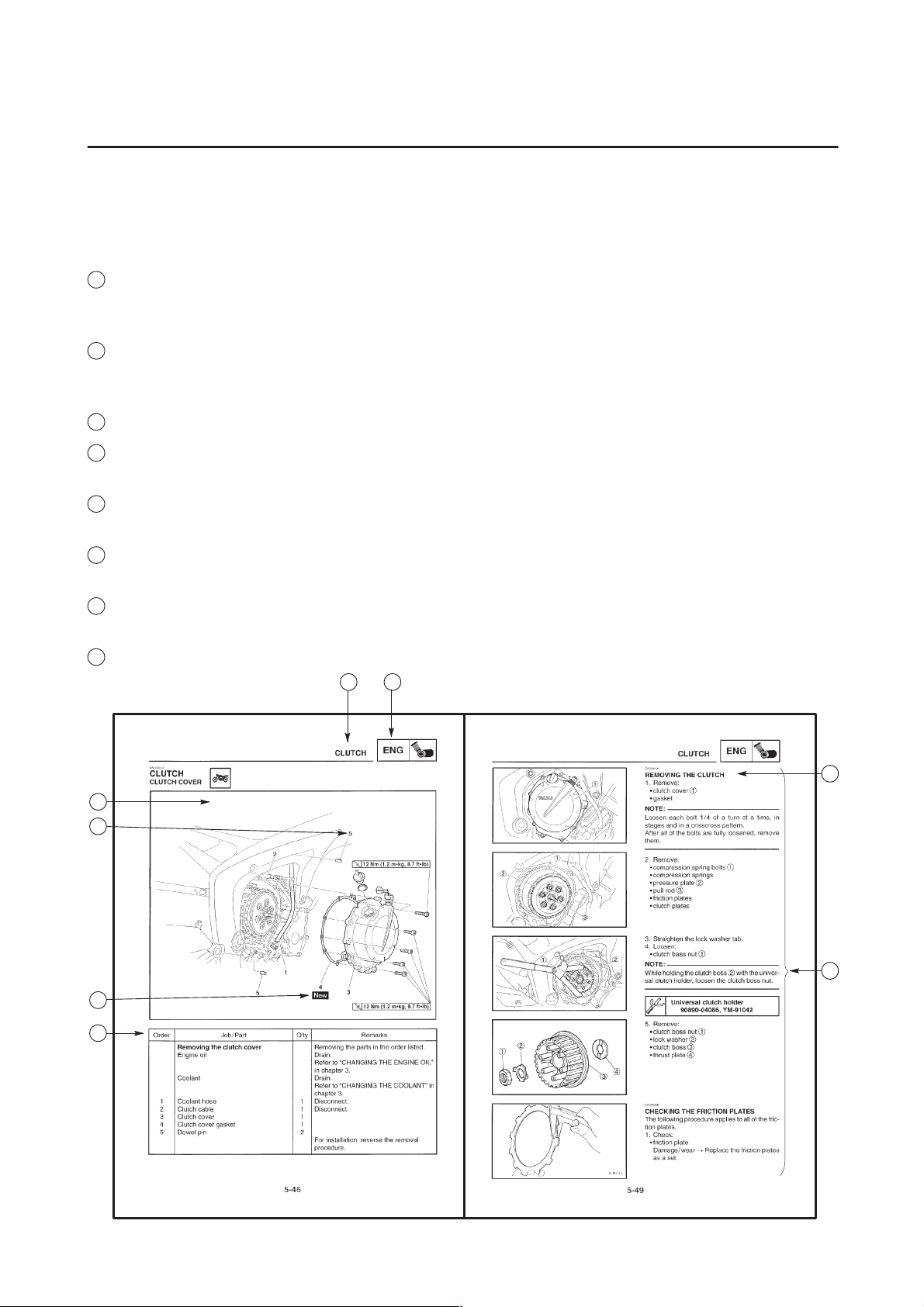
1
The manual is divided into chapters. An abbreviation and symbol in the upper right corner of each
page indicate the current chapter.
Refer to “SYMBOLS”.
2
Each chapter is divided into sections. The current section title is shown at the top of each page,
except in Chapter 3 (“PERIODIC CHECKS AND ADJUSTMENTS”), where the sub-section title(s) appears.
3
Sub-section titles appear in smaller print than the section title.
4
To help identify parts and clarify procedure steps, there are exploded diagrams at the start of each
removal and disassembly section.
5
Numbers are given in the order of the jobs in the exploded diagram. A circled number indicates a
disassembly step.
6
Symbols indicate parts to be lubricated or replaced.
Refer to “SYMBOLS”.
7
A job instruction chart accompanies the exploded diagram, providing the order of jobs, names of
parts, notes in jobs, etc.
8
Jobs requiring more information (such as special tools and technical data) are described sequentially.
4
5
6
7
12
3
8
1
GEN
INFO
3
CHK
ADJ
5
ENG
7
FI ELEC
2
SPEC
4
CHAS
6
COOL
8
EAS00008
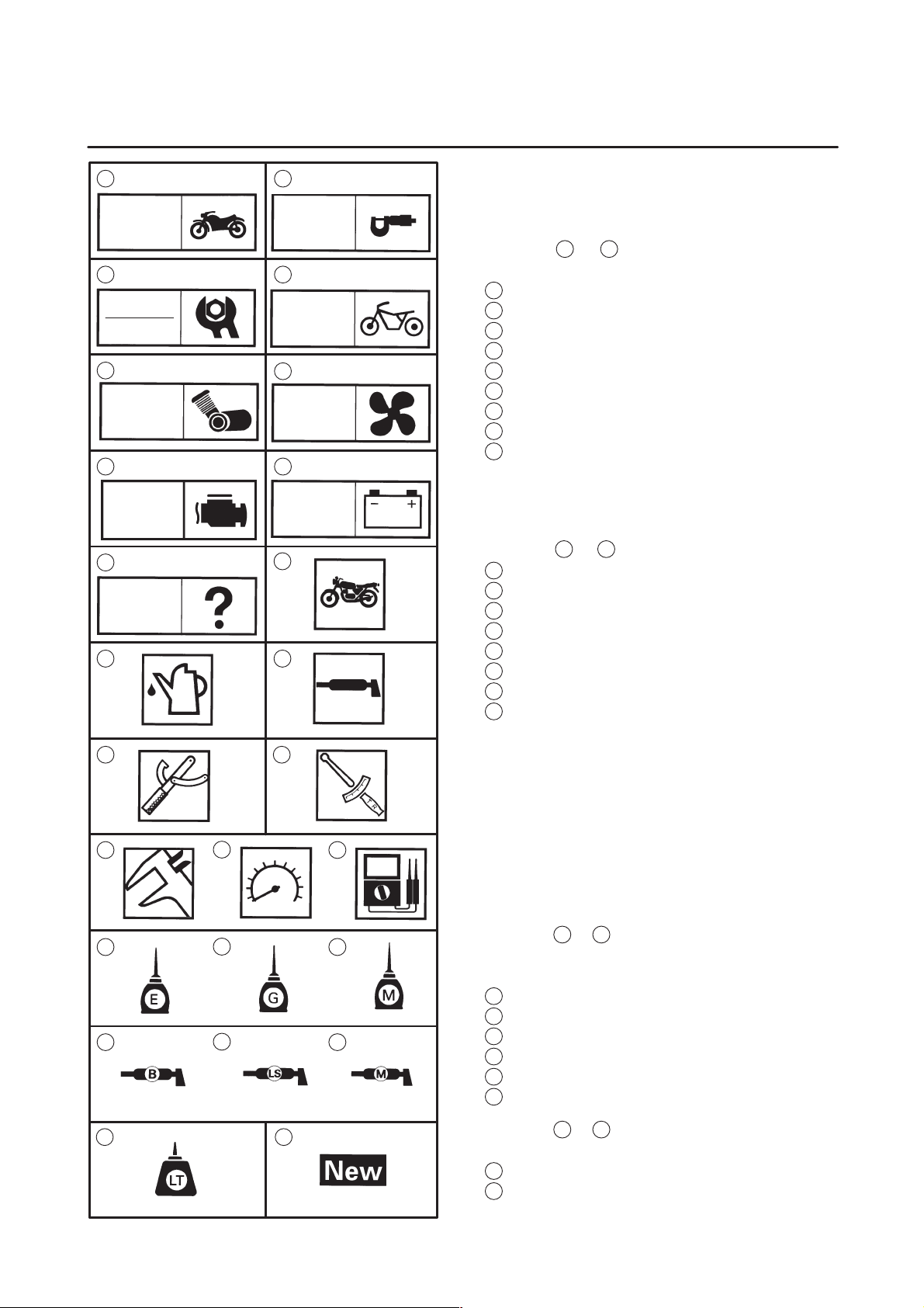
SYMBOLS
The following symbols are not relevant to every
vehicle.
Symbols
chapter.
General information
1
Specifications
2
Periodic checks and adjustments
3
Chassis
4
Engine
5
Cooling system
6
Fuel injection system
7
Electrical system
8
Troubleshooting
9
1
to 9 indicate the subject of each
9
10
TRBL
SHTG
11 12
1413
16 1715
19 2018
22
Symbols 10 to 17 indicate the following.
10
Serviceable with engine mounted
11
Filling fluid
12
Lubricant
13
Special tool
14
Tightening torque
15
Wear limit, clearance
16
Engine speed
17
Electrical data
Symbols 18 to 23 in the exploded diagrams indicate the types of lubricants and lubrication
points.
18
Engine oil
19
Gear oil
20
2321
Molybdenum-disulfide oil
21
Wheel-bearing grease
22
Lithium-soap-based grease
23
Molybdenum-disulfide grease
24 25
Symbols 24 to 25 in the exploded diagrams indicate the following.
24
Apply locking agent (LOCTITE)
25
Replace the part
EAS00012
TABLE OF CONTENTS
GENERAL INFORMATION
SPECIFICATIONS
PERIODIC CHECKS AND
ADJUSTMENTS
CHASSIS
ENGINE
GEN
INFO
SPEC
CHK
ADJ
CHAS
ENG
1
2
3
4
5
COOLING SYSTEM
FUEL INJECTION SYSTEM
ELECTRICAL SYSTEM
TROUBLESHOOTING
COOL
FI
ELEC
TRBL
SHTG
6
7
8
9

GEN
INFO
CHAPTER 1
GENERAL INFORMATION
MOTORCYCLE IDENTIFICATION 1-1. . . . . . . . . . . . . . . . . . . . . . . . . . . . . .
VEHICLE IDENTIFICATION NUMBER 1-1. . . . . . . . . . . . . . . . . . . . . . . .
MODEL LABEL 1-1. . . . . . . . . . . . . . . . . . . . . . . . . . . . . . . . . . . . . . . . . . . .
FEATURES 1-2. . . . . . . . . . . . . . . . . . . . . . . . . . . . . . . . . . . . . . . . . . . . . . . . . .
OUTLINE OF FI SYSTEM 1-2. . . . . . . . . . . . . . . . . . . . . . . . . . . . . . . . . . .
FI SYSTEM 1-3. . . . . . . . . . . . . . . . . . . . . . . . . . . . . . . . . . . . . . . . . . . . . . .
INSTRUMENT FUNCTION 1-4. . . . . . . . . . . . . . . . . . . . . . . . . . . . . . . . . .
IMPORTANT INFORMATION 1-6. . . . . . . . . . . . . . . . . . . . . . . . . . . . . . . . . . .
PREPARATION FOR REMOVAL AND DISASSEMBLY 1-6. . . . . . . . .
REPLACEMENT PARTS 1-6. . . . . . . . . . . . . . . . . . . . . . . . . . . . . . . . . . . .
GASKETS, OIL SEALS AND O-RINGS 1-6. . . . . . . . . . . . . . . . . . . . . . .
LOCK WASHERS/PLATES AND COTTER PINS 1-7. . . . . . . . . . . . . .
BEARINGS AND OIL SEALS 1-7. . . . . . . . . . . . . . . . . . . . . . . . . . . . . . . .
CIRCLIPS 1-7. . . . . . . . . . . . . . . . . . . . . . . . . . . . . . . . . . . . . . . . . . . . . . . . .
CHECKING THE CONNECTIONS 1-8. . . . . . . . . . . . . . . . . . . . . . . . . . . . . . .
SPECIAL TOOLS 1-9. . . . . . . . . . . . . . . . . . . . . . . . . . . . . . . . . . . . . . . . . . . . .

GEN
INFO
MOTORCYCLE IDENTIFICATION
EAS00014
GENERAL INFORMATION
MOTORCYCLE IDENTIFICATION
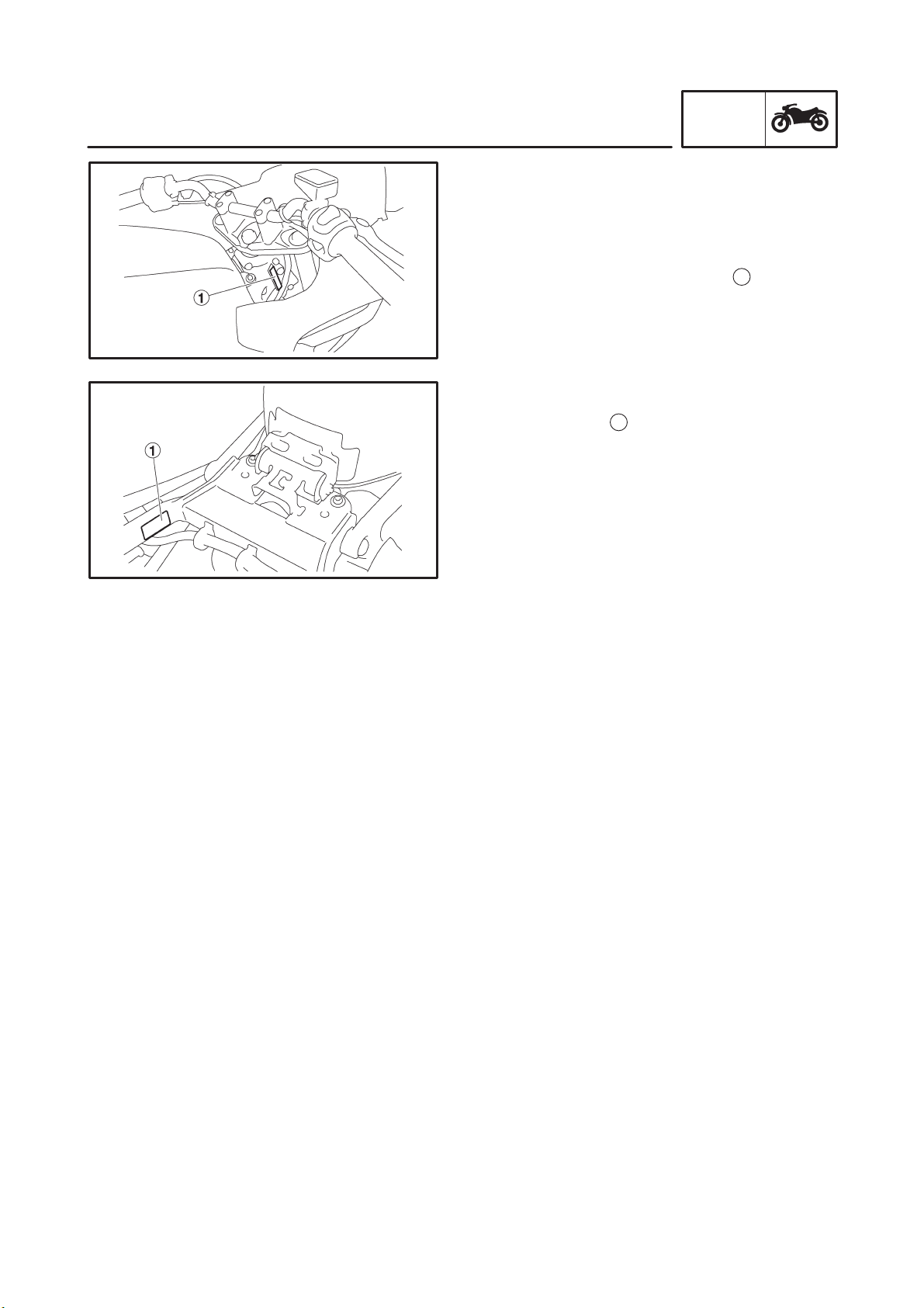
EAS00017
VEHICLE IDENTIFICATION NUMBER
The vehicle identification number
into the right side of the steering head pipe.
EAS00018
MODEL LABEL
1
The model label
information will be needed to order spare parts.
is affixed to the frame. This
GEN
INFO
1
is stamped
1-1
GEN
FEATURES
EAS00896
FEATURES
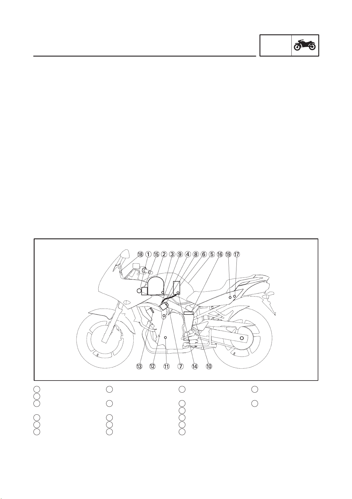
OUTLINE OF FI SYSTEM
The main function of a fuel supply system is to provide fuel to the combustion chamber at the optimum
air-fuel ratio in accordance with the engine operating conditions and the atmospheric temperature.
In the conventional carburetor system, the air-fuel ratio of the mixture that is supplied to the combustion
chamber is created by the volume of the intake air and the fuel that is metered by the jet used in the
respective carburetor.
Despite the same volume of intake air, the fuel volume requirement varies by the engine operating
conditions, such as acceleration, deceleration, or operating under a heavy load. Carburetors that meter the fuel through the use of jets have been provided with various auxiliary devices, so that an optimum air-fuel ratio can be achieved to accommodate the constant changes in the operating conditions
of the engine.
As the requirements for the engine to deliver more performance and cleaner exhaust gases increase, it
becomes necessary to control the air-fuel ratio in a more precise and finely tuned manner. To accommodate this need, this model has adopted an electronically controlled fuel injection (FI) system, in
place of the conventional carburetor system. This system can achieve an optimum air-fuel ratio required by the engine at all times by using a microprocessor that regulates the fuel injection volume
according to the engine operating conditions detected by various sensors.
The adoption of the FI system has resulted in a highly precise fuel supply, improved engine response,
better fuel economy, and reduced exhaust emissions. Furthermore, the air induction system (AI system) has been placed under computer control together with the FI system in order to realize cleaner
exhaust gases.
INFO
1 Ignition coil
2 Air filter case
3 Intake air temperature
sensor
4 Fuel delivery hose
5 Fuel tank
6 Fuel pump
7 Intake air pressure
sensor
8 Throttle position sen-
sor
9 Fuel injector
10 Catalytic converter
11 Crankshaft position
sensor
12 Coolant temperature
sensor
13 Spark plug
14 Pressure regulator
15 Battery
16 ECU
17 Fuel injection system
relay
1-2
18 Engine trouble warn-
ing light
19 Lean angle cut-off
switch
GEN
FEATURES
EAS00897
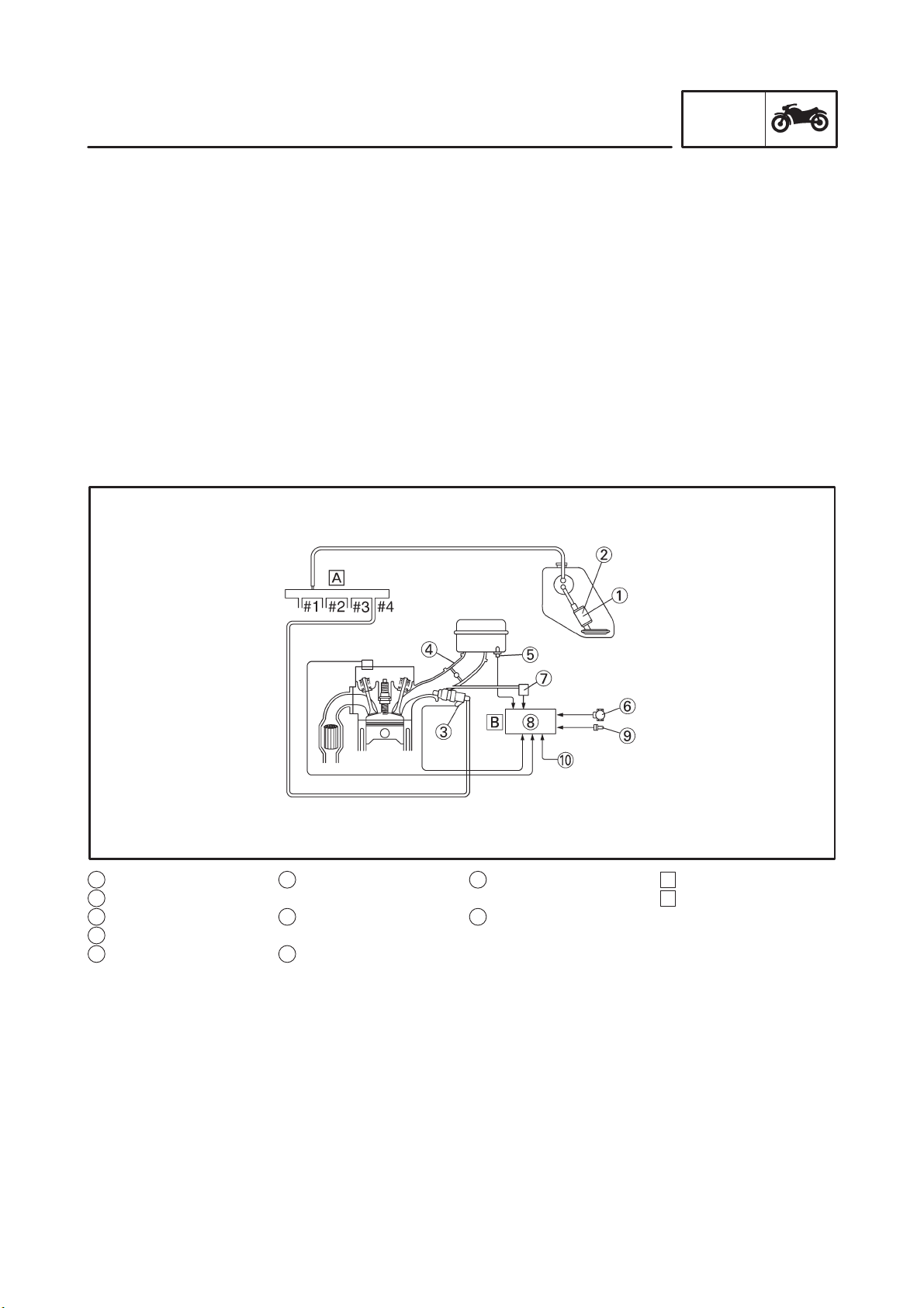
FI SYSTEM
The fuel pump delivers fuel to the injector via the fuel filter. The pressure regulator maintains the fuel
pressure that is applied to the injector at only 250 kPa (2.5 kg/ cm
signal from the ECU energizes the injector, the fuel passage opens, causing the fuel to be injected into
the intake manifold only during the time the passage remains open. Therefore, the longer the length of
time the injector is energized (injection duration), the greater the volume of fuel that is supplied. Conversely, the shorter the length of time the injector is energized (injection duration), the lesser the volume of fuel that is supplied.
The injection duration and the injection timing are controlled by the ECU. Signals that are input from the
throttle position sensor, crankshaft position sensor, intake air pressure sensor, intake temperature
sensor and coolant temperature sensor enable the ECU to determine the injection duration. The injection timing is determined through the signals from the crankshaft position sensor. As a result, the volume of fuel that is required by the engine can be supplied at all times in accordance with the driving
conditions.
Illustration is for reference only.
2
). Accordingly, when the energizing
INFO
1 Fuel pump
2 Pressure regulator
3 Fuel injector
4 Throttle body
5 Intake air temperature
sensor
6 Throttle position sen-
sor
7 Intake air pressure
sensor
8 ECU
9 Coolant temperature
sensor
10 Crankshaft position
sensor
1-3
A Fuel system
B Control system
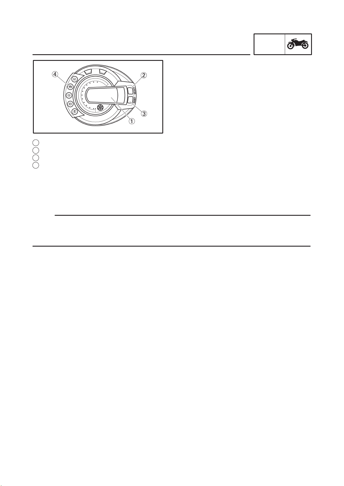
1 Multi-function display
2 “SELECT” button
3 “RESET” button
4 Engine trouble warning light
GEN
FEATURES
INSTRUMENT FUNCTION
Multi-function display
The multi-function display is equipped with the
following:
S a speedometer (which shows the riding
speed)
S an odometer (which shows the total distance
traveled)
S two tripmeters (which show the distance
traveled since they were last set to zero)
S a fuel reserve tripmeter (which shows the
distance traveled since the bottom segment
of the fuel meter started flashing)
S a tachometer (which shows the engine
speed)
S a fuel meter
S a water temperature
S a clock
S a intake air temperature
S a self-diagnosis device
INFO
NOTE:
S Be sure to turn the key to “ON” before using the “SELECT” and ”RESET” buttons.
S For the U.K. only: To switch the speedometer and odometer /tripmeter display between kilometers
and miles, press the “SELECT” button for at least two seconds.
Odometer, tripmeter and tachometer modes
Pushing the “SELECT” button switches the display between the odometer mode “ODO” and the tripmeter modes “TRIP 1” and “TRIP 2” and the tachometer mode “E” is the following order:
ODO ! TRIP 1 ! TRIP 2 ! (TRIP F) ! E ! ODO
When approximately 3.6 L of fuel remain in the fuel tank, the bottom segment of the fuel meter will start
flashing, and the odometer display will automatically change to the fuel reserve tripmeter mode “TRIP
F” and start counting the distance traveled from that point. In that case, pushing the “SELECT” button
switches the display between the various tripmeter and odometer modes in the following order:
TRIP-F ! E ! ODO ! TRIP 1 ! TRIP 2 ! TRIP F
To reset a tripmeter, select it by pushing the “SELECT” button, and then push the “RESET” button for at
least one second. If you do not reset the fuel reserve tripmeter manually, it will reset itself automatically
and the display will return to the prior mode after refueling and traveling 5 km (3.1 mi).
Tachometer mode
Displays the digital indication of the engine speed on the odometer section.
Air intake temperature indicator.
When “ODO” is displayed, pressing the “RESET” for a long time allows the indicator to switch displays
between Clock and Air intake temperature. (It activates the clock indication when the main switch is
turned OFF.)
In the Co adjustment mode, the indication automatically changes from clock (Air intake temperature) to
the engine speed.
1-4

GEN
FEATURES
Clock mode
To set the clock:
1. Push the “SELECT” button and “RESET” button together for at least two seconds.
2. When the hour digits start flashing, push the “RESET” button to set the hours.
3. Push the “SELECT” button, and the minute digits will start flashing.
4. Push the “RESET” button to set the minutes.
5. Push the “SELECT” button and then release it to start the clock.
INFO
1-5
IMPORTANT INFORMATION
EAS00020
IMPORTANT INFORMATION
PREPARATION FOR REMOVAL AND
DISASSEMBLY
1. Before removal and disassembly, eliminate
all dirt, mud, dust and foreign material.
2. Use only the proper tools and cleaning
equipment.
Refer to the “SPECIAL TOOLS”.
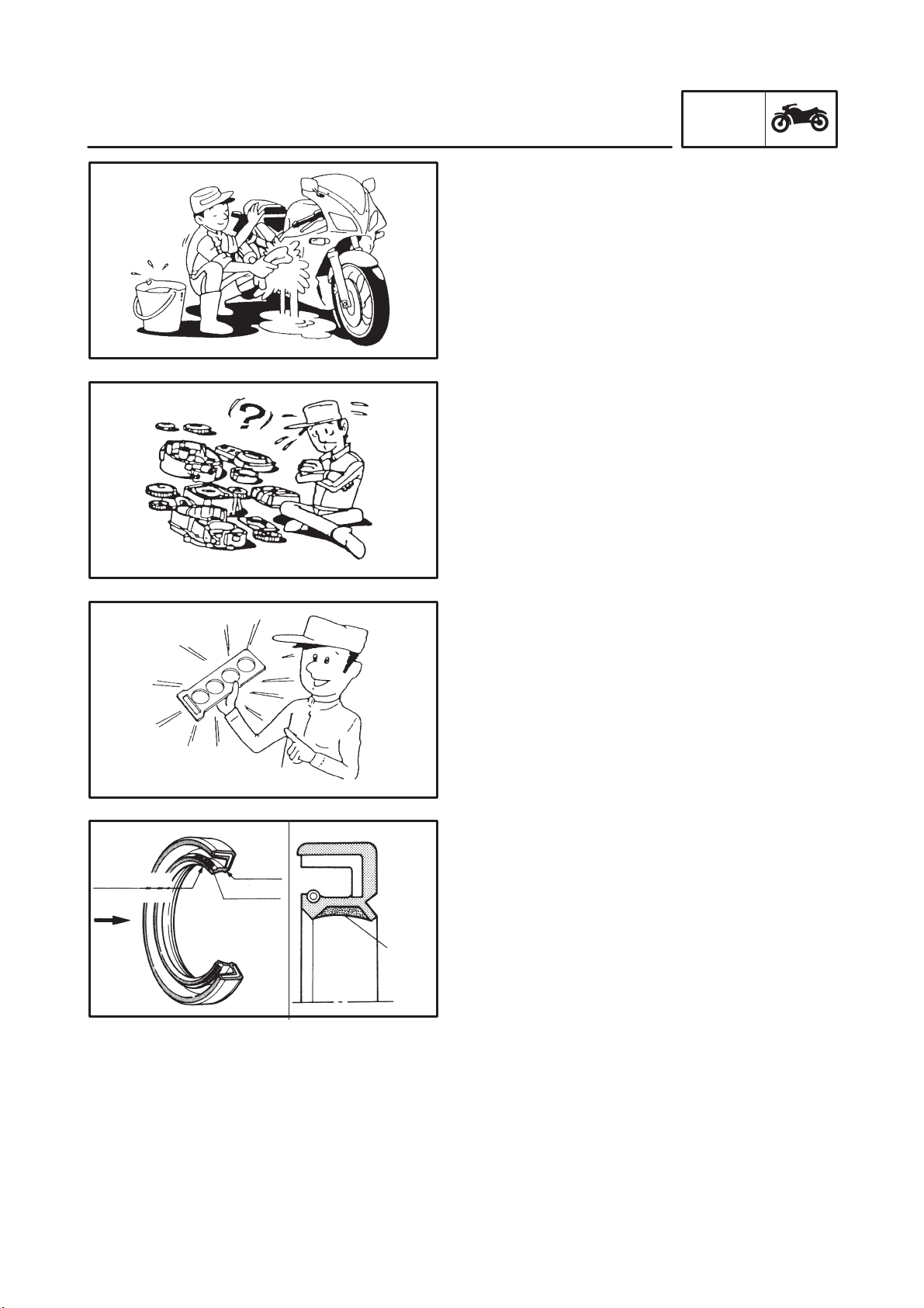
3. When disassembling, always keep mated
parts together. This includes gears, cylinders, pistons and other parts that have been
“mated” through normal wear. Mated parts
must always be reused or replaced as an assembly.
4. During disassembly, clean all of the parts
and place them in trays in the order of disassembly. This will speed up assembly and allow for the correct installation of all parts.
5. Keep all parts away from any source of fire.
GEN
INFO
lip
oil
lip
spring
grease
EAS00021
REPLACEMENT PARTS
Use only genuine Yamaha parts for all replacements. Use oil and grease recommended by
Yamaha for all lubrication jobs. Other brands
may be similar in function and appearance, but
inferior in quality.
EAS00022
GASKETS, OIL SEALS AND O-RINGS
1. When overhauling the engine, replace all
gaskets, seals and O-rings. All gasket surfaces, oil seal lips and O-rings must be
cleaned.
2. During reassembly, properly oil all mating
parts and bearings and lubricate the oil seal
lips with grease.
1-6
IMPORTANT INFORMATION
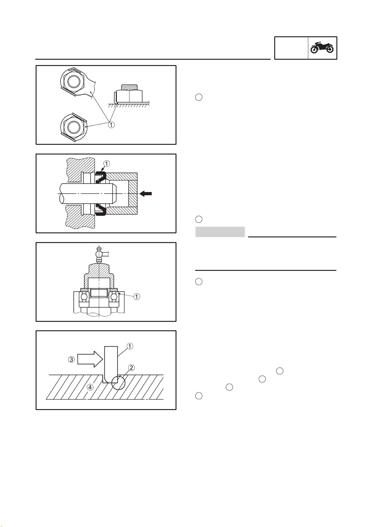
EAS00023
LOCK WASHERS/ PLATES AND COTTER
PINS
After removal, replace all lock washers/ plates
1
and cotter pins. After the bolt or nut has been
tightened to specification, bend the lock tabs
along a flat of the bolt or nut.
EAS00024
BEARINGS AND OIL SEALS
Install bearings and oil seals so that the
manufacturer’s marks or numbers are visible.
When installing oil seals, lubricate the oil seal
lips with a light coat of lithium-soap-based
grease. Oil bearings liberally when installing, if
appropriate.
Oil seal
1
GEN
INFO
CAUTION:
Do not spin the bearing with compressed air
because this will damage the bearing surfaces.
Bearing
1
EAS00025
CIRCLIPS
Before reassembly, check all circlips carefully
and replace damaged or distorted circlips. Always replace piston pin clips after one use.
When installing a circlip
sharp-edged corner
3
the thrust
Shaft
4
that the circlip receives.
1
, make sure the
2
is positioned opposite
1-7
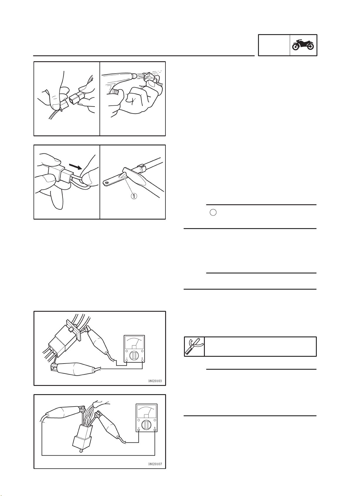
CHECKING THE CONNECTIONS
EAS00026
CHECKING THE CONNECTIONS
Check the leads, couplers, and connectors for
stains, rust, moisture, etc.
1. Disconnect:
S lead
S coupler
S connector
2. Check:
S lead
S coupler
S connector
Moisture ! Dry with an air blower.
Rust/ stains ! Connect and disconnect several times.
3. Check:
S all connections
Loose connection ! Connect properly.
NOTE:
If the pin
up.
1
on the terminal is flattened, bend it
GEN
INFO
4. Connect:
S lead
S coupler
S connector
NOTE:
Make sure all connections are tight.
5. Check:
S continuity
(with the pocket tester)
Pocket tester
90890-03112, YU-3112
NOTE:
S If there is no continuity, clean the terminals.
S When checking the wire harness, perform
steps (1) to (3).
S As a quick remedy, use a contact revitalizer
available at most part stores.
1-8
GEN
SPECIAL TOOLS
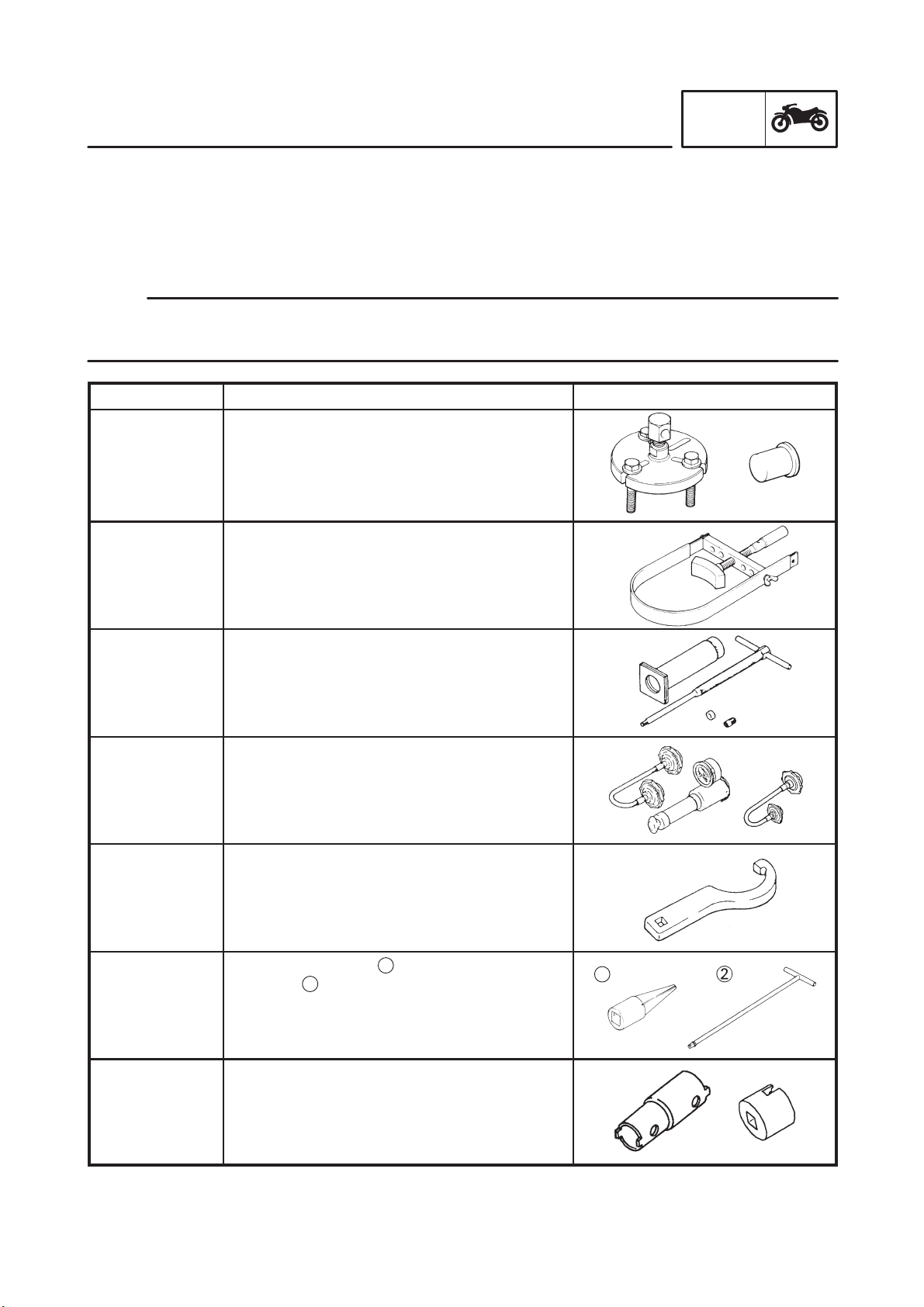
EAS00027
SPECIAL TOOLS
The following special tools are necessary for complete and accurate tune-up and assembly. Use only
the appropriate special tools as this will help prevent damage caused by the use of inappropriate tools
or improvised techniques. Special tools, part numbers or both may differ depending on the country.
When placing an order, refer to the list provided below to avoid any mistakes.
NOTE:
S For U.S.A. and Canada, use part number starting with “YM-”, “YU-”, or “ACC-”.
S For others, use part number starting with “90890-”.
INFO
Tool No.
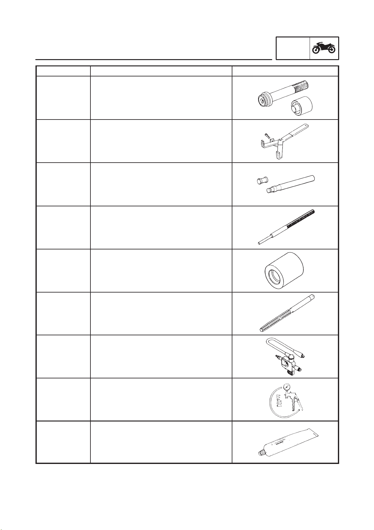
Flywheel puller
90890-01362
YU-33270-B
Adapter
90890-04089
YM-33282
90890-01701
YS-01880-A
90890-01304
YU-01304
Radiator cap
tester
90890-01325
YU-24460-01
Adapter
90890-01352
YU-33984
Tool name /Function Illustration
Flywheel puller
Adapter
This tool is used to remove the generator rotor.
Sheave holder
This tool is used to hold the generator rotor
when removing or installing the generator rotor bolt or pickup coil rotor bolt.
Piston pin puller
This tool is used to remove the piston pins.
Radiator cap tester
Adapter
These tools are used to check the cooling
system.
90890-01403
YU-33975
90890-01460
-01326
Pivot shaft
wrench
90890-01471
YM-01471
Pivot shaft wrench
adapter
90890-01476
Steering nut wrench
This tool is used to loosen or tighten the steering stem ring nuts.
Damper rod holder
T-handle
2
1
These tool are used for holding the damper
rod when removing or installing the damper
rod.
Pivot shaft wrench
Pivot shaft wrench adapter
This tool is used to loosen or tighten the pivot
adjust bolt and engine mount adjust bolt.
1-9
1
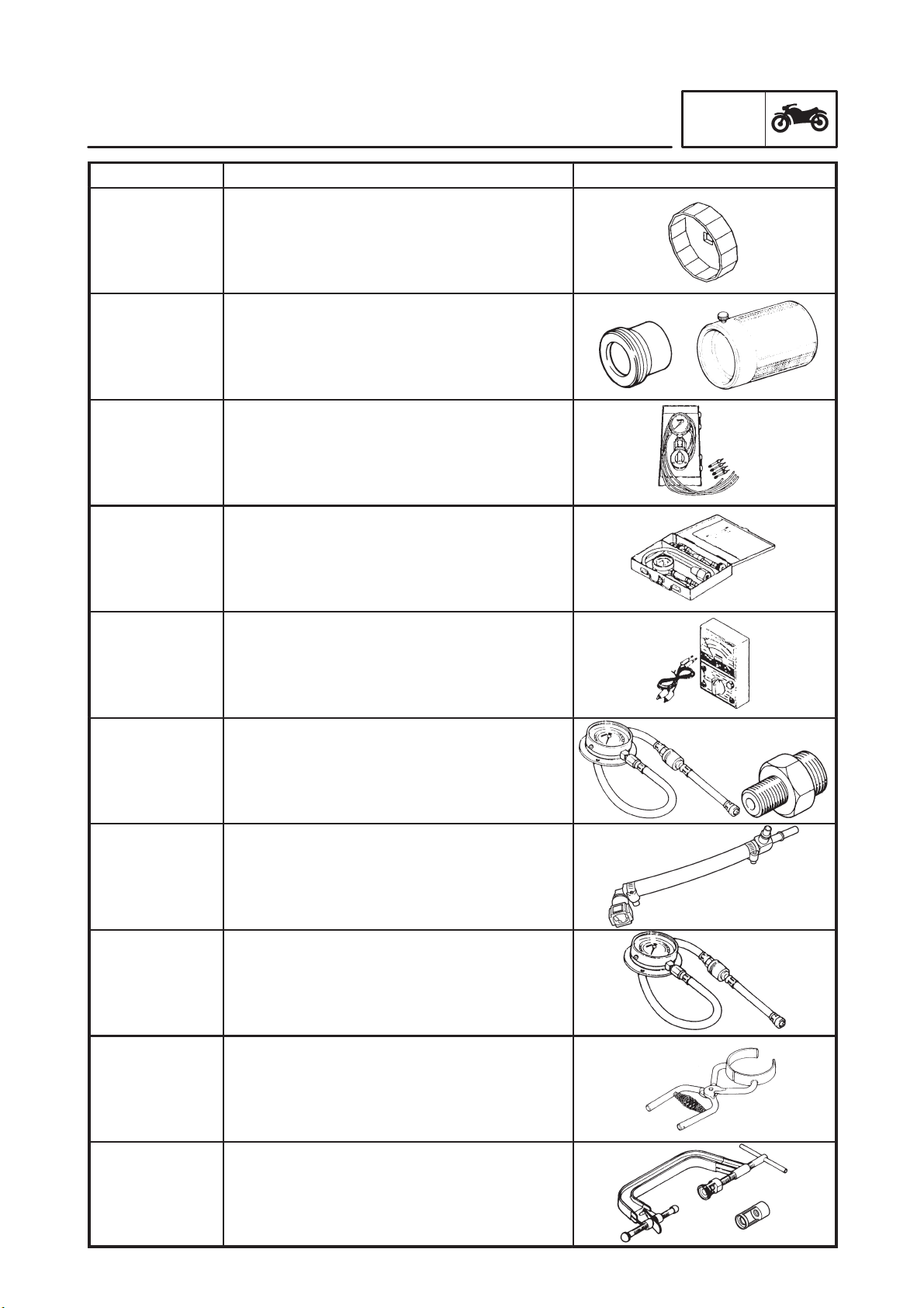
SPECIAL TOOLS
Tool No. Tool name /Function Illustration
Oil filter wrench
90890-01426
YU-38411
Fork seal driver
90890-01367
YM-33963
Fork seal driver
attachment
90890-01374
YM-8020-A
Vacuum gauge
90890-03094
YU-08030
Compression
gauge
90890-03081
YU-33223
Adapter
90890-04136
This tool is needed to loosen or tighten the oil
filter cartridge.
Fork seal driver weight
Fork seal driver attachment
This tool is used to install the front fork’s oil
seal and dust seal.
Vacuum gauge
This gauge is used to synchronize the carburetors.
Compression gauge
Adapter
These tools are used to measure engine
compression.
Pocket tester
GEN
INFO
90890-03112
YU-3112
Oil pressure
gauge
90890-03153
YU-03153
Adapter
90890-03139
90890-03176
YM-03176
90890-03153
YU-03153
90890-04044
YM-04044
Valve spring
compressor
90890-04019
YM-04019
Attachment
90890-04108
YM-01253
This tool is used to check the electrical system.
Oil pressure gauge
Adapter
These tools are used to measure engine oil
pressure.
Fuel pressure adapter
This tool is needed to measure fuel pressure.
Pressure gauge
This tool used is to measure fuel pressure.
Piston ring compressor
This tool is used to compress piston rings
when installing the cylinder.
Valve spring compressor
Attachment
These tools are used to remove or install the
valve assemblies.
1-10
SPECIAL TOOLS
Tool No. Tool name /Function Illustration
Middle driven shaft
bearing driver
90890-04058
YM-4058
Mechanical seal
installer
90890-04078
YM-33221
Middle driven shaft bearing driver
Mechanical seal installer
These tools are used to install the water pump
seal.
Clutch holding tool
GEN
INFO
90890-04086
YM-91042
90890-04101
90890-04111
90890-04112
90890-04113
YM-04113
This tool is used to hold the clutch boss
when removing or installing the clutch boss
nut.
Valve lapper
This tool is needed to remove and install
the valve lifter.
Valve guide remover (φ4)
This tool is used to remove or install the valve
guides.
Valve guide installer (φ4)
This tool is used to install the valve guides.
Valve guide reamer (φ4)
This tool is used to rebore the new valve
guides.
Ignition checker
90890-06754
YM-34487
90890-06756
YB-35956
90890-85505
ACC-1100105-01
This tool is used to check the ignition system
components.
Vacuum/pressure pump gauge set
This tool used to measure the vacuum pressure.
Yamaha bond No. 1215
This bond is used to seal two mating surfaces
(e.g., crankcase mating surfaces).
1-11


SPEC
CHAPTER 2
SPECIFICATIONS
GENERAL SPECIFICATIONS 2-1. . . . . . . . . . . . . . . . . . . . . . . . . . . . . . . . . .
ENGINE SPECIFICATIONS 2-2. . . . . . . . . . . . . . . . . . . . . . . . . . . . . . . . . . . .
CHASSIS SPECIFICATIONS 2-10. . . . . . . . . . . . . . . . . . . . . . . . . . . . . . . . . . .
ELECTRICAL SPECIFICATIONS 2-14. . . . . . . . . . . . . . . . . . . . . . . . . . . . . . .
CONVERSION TABLE 2-17. . . . . . . . . . . . . . . . . . . . . . . . . . . . . . . . . . . . . . . . .
GENERAL TIGHTENING TORQUE SPECIFICATIONS 2-17. . . . . . . . . . . .
TIGHTENING TORQUES 2-18. . . . . . . . . . . . . . . . . . . . . . . . . . . . . . . . . . . . . .
ENGINE TIGHTENING TORQUES 2-18. . . . . . . . . . . . . . . . . . . . . . . . . . .
CHASSIS TIGHTENING TORQUES 2-21. . . . . . . . . . . . . . . . . . . . . . . . . .
LUBRICATION POINTS AND LUBRICANT TYPES 2-23. . . . . . . . . . . . . . .
ENGINE 2-23. . . . . . . . . . . . . . . . . . . . . . . . . . . . . . . . . . . . . . . . . . . . . . . . . .
CHASSIS 2-24. . . . . . . . . . . . . . . . . . . . . . . . . . . . . . . . . . . . . . . . . . . . . . . . .
COOLING SYSTEM DIAGRAMS 2-25. . . . . . . . . . . . . . . . . . . . . . . . . . . . . . .
ENGINE OIL LUBRICATION CHART 2-29. . . . . . . . . . . . . . . . . . . . . . . . . . . .
LUBRICATION DIAGRAMS 2-30. . . . . . . . . . . . . . . . . . . . . . . . . . . . . . . . . . . .
CABLE ROUTING 2-36. . . . . . . . . . . . . . . . . . . . . . . . . . . . . . . . . . . . . . . . . . . .
SPEC
GENERAL SPECIFICATIONS
SPEC
SPECIFICATIONS
GENERAL SPECIFICATIONS
Item Standard Limit
Model code 5VX1 (EUR), 5VX2 (AUS) SSS
Dimensions
Overall length
Overall width
Overall height
Seat height
Wheelbase
Minimum ground clearance
Minimum turning radius
Weight
Wet (with oil and a full fuel tank)
Maximum load (except motorcycle)
2,095 mm (82.5 in)
750 mm (29.5 in)
1,215 mm (47.8 in)
795 mm (31.3 in)
1,440 mm (56.7 in)
145 mm (5.71 in)
2,800 mm (110.2 in)
207 kg (456 lb)
190 kg (419 lb)
SSS
SSS
SSS
SSS
SSS
SSS
SSS
SSS
SSS
2-1
ENGINE SPECIFICATIONS
Item Standard Limit
Engine
Engine type
Displacement
Cylinder arrangement
Bore stroke
Compression ratio
Engine idling speed
Vacuum pressure at engine idling
speed
Standard compression pressure
(at sea level)
Fuel
Recommended fuel
Fuel tank capacity
Total (including reserve)
Reserve only
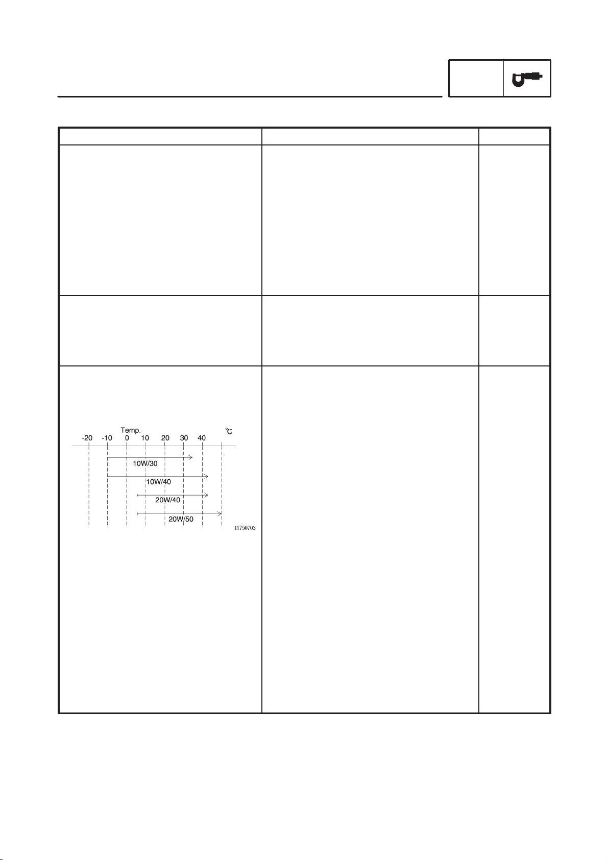
Engine oil
Lubrication system
Recommended oil
ENGINE SPECIFICATIONS
Liquid-cooled, 4-stroke, DOHC
600 cm
Forward-inclined parallel 4-cylinder
65.5 44.5 mm (2.58 1.75 in)
12.2 : 1
1,250 X 1,350 r/ min
29 kPa (218 mmHg, 8.6 inHg)
1,550 kPa (15.50 kg/ cm
220.46 psi) at 400 r/ min
Regular unleaded gasoline only
19.4 L (4.25 lmp gal, 5.1 US gal)
3.6 L (0.79 lmp gal, 0.9 US gal)
Wet sump
3
(36.61 cu.in)
2
,15.50 bar,
SPEC
SSS
SSS
SSS
SSS
SSS
SSS
SSS
SSS
SSS
SSS
SSS
SSS
Quantity
Total amount
Without oil filter cartridge
replacement
With oil filter cartridge replacement
Oil pressure
Engine oil temperature
Relief valve opening pressure
Refer to the chart for the engine oil grade
3.4 L (2.99 Imp qt, 3.59 US qt)
2.5 L (2.20 lmp qt, 2.64 US qt)
2.8 L (2.47 lmp qt, 2.96 US qt)
240 kPa at 6,600 r/ min
(2.4 kg/ cm
(2.4 bar at 6,600 r/ min)
(34.1 psi at 6,600 r/ min)
96_C (205_F)
450 X 550 kPa (4.5 X 5.5 kg/ cm
4.5 X 5.5 bar, 65.3 X 79.8 psi)
2
at 6,600 r/ min)
2
,
SSS
SSS
SSS
SSS
SSS
2-2
ENGINE SPECIFICATIONS
Item Standard Limit
Oil filter
Oil filter type
Bypass valve opening pressure
Oil pump
Oil pump type
Inner-rotor-to-outer-rotor-tip
clearance
Outer-rotor-to-oil-pump-housing
clearance
Cooling system
Radiator capacity
Radiator cap opening pressure
Radiator core
Width
Height
Depth
Coolant reservoir
Capacity
Water pump
Water pump type
Reduction ratio
Max. impeller shaft tilt
Starting system type Electric starter
Formed
80 X 120 kPa (0.8 X 1.2 kg/ cm
0.8 X 1.2 bar, 11.6 X 17.4 psi)
Trochoid
0.03 X 0.09 mm
(0.0012 X 0.0035 in)
0.03 X 0.08 mm
(0.0012 X 0.0032 in)
2.0 L (1.76 lmp pt, 2.11 US qt)
93.3 X 122.7 kPa (0.93 X 1.23 kg/cm
0.93 X 1.23 bar, 13.5 X 17.8 psi)
300 mm (11.81 in)
188 mm (7.4 in)
24 mm (0.94 in)
0.27 L (0.24 lmp qt, 0.29 US qt)
Single suction centrifugal pump
86/ 44 31 /31 (1.955)
SSS
2
,
SPEC
SSS
SSS
SSS
0.15 mm
(0.0059 in)
0.15 mm
(0.0059 in)
2
,
SSS
SSS
SSS
SSS
SSS
SSS
SSS
0.15 mm
(0.006 in)
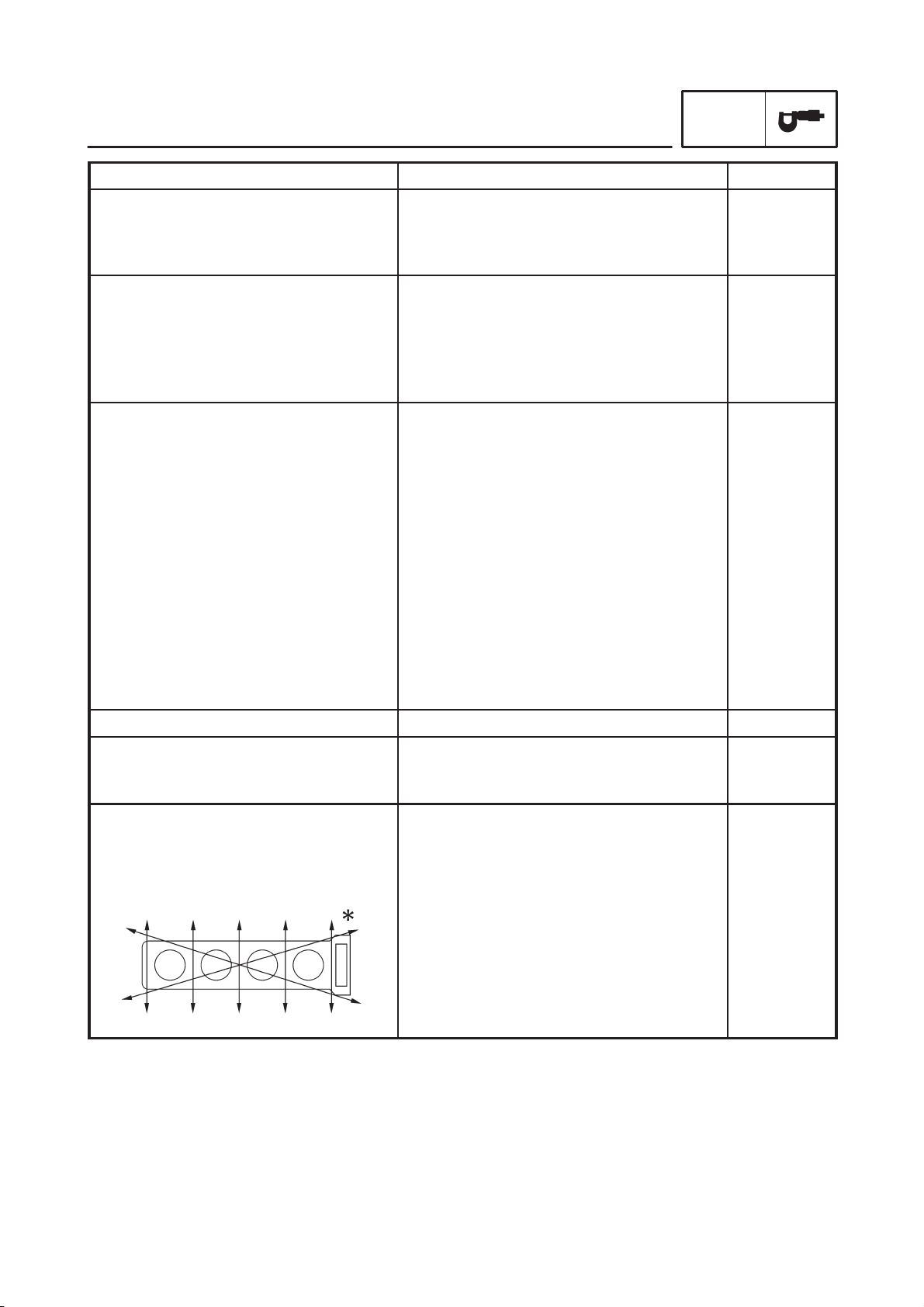
Spark plugs
Model (manufacturer) quantity
Spark plug gap
Cylinder head
Volume
Max. warpage
CR9EK (NGK) 4
0.6 X 0.7 mm (0.0236 X 0.0276 in)
10.3 X 10.9 cm3 (0.63 X 0.67 cu.in)
SSS
SSS
SSS
SSS
0.05 mm
(0.002 in)
2-3
Item Standard Limit
Camshafts
Drive system
Camshaft cap inside diameter
Camshaft journal diameter
Camshaft-journal-to-camshaftcap clearance
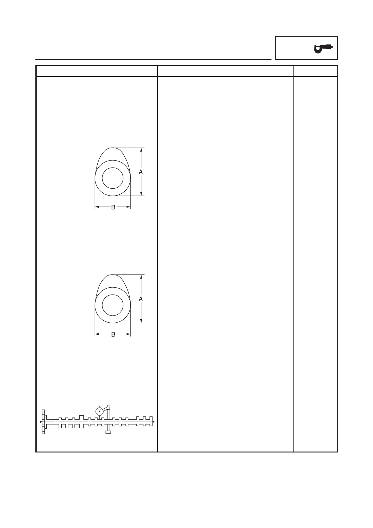
Intake camshaft lobe dimensions
ENGINE SPECIFICATIONS
Chain drive (right)
23.008 X 23.029 mm (0.9058 X 0.9067 in)
22.967 X 22.980 mm (0.9042 X 0.9047 in)
0.028 X 0.062 mm (0.0011 X 0.0024 in)
SPEC
SSS
SSS
SSS
0.08 mm
(0.0032 in)
Measurement A
Measurement B
Exhaust camshaft lobe dimensions
Measurement A
Measurement B
Max. camshaft runout
32.45 X 32.55 mm (1.278 X 1.282 in)
24.95 X 25.05 mm (0.982 X 0.986 in)
32.45 X 32.55 mm (1.278 X 1.282 in)
24.95 X 25.05 mm (0.982 X 0.986 in)
SSS
32.40 mm
(1,276 in)
24.90 mm
(0.980 in)
32.40 mm
(1.276 in)
24.90 mm
(0.980 in)
0.06 mm
(0.0024 in)
2-4
 Loading...