

YAMAHA FX500 User Manual

®
YAMAHA
AUTHORIZED
PRODUCT MANUAL
SIMUL-EFFECT PROCESSOR
YAMAHA
Operation Manual

Congratulations!
You are the proud owner of a Yamaha FX500 SIMUL-EFFECT
PROCESSOR. The FX500 is a high-performance digital effect device
which provides a chain
programming capability so you can create “custom” effect chains to suit
your own specific musical requirements. With programmable compressor,
distortion, equalizer, modulation and reverb/delay effect stages, the
FX500 gives you a complete state-of-the-art signal-processing system in
one compact package. 60 superlative preset effect programs are provided
that you can simply select and use right away, while 30 RAM memory
locations can be used to store your original signal-processing creations.
Furthermore, the effects are all created using leading-edge Yamaha
digital signal processing technology, so the sound is nothing less than
superb.
Please read through this operation manual thoroughly while learning to
use your FX500, in order to take
capabilities it provides —
reference!
of
up
to 5 different effects,
full
advantage
and keep the manual in a safe place
and extensive
of
all the sophisticated
for later
1

CONTENTS
1.
Precautions
2. The FX500: What It Is and What It Does
Effects
Memory
MIDIControl
3.Connections:
4.TheControls: A Quick Operation
5. The MEMORY Mode:
Selecting
6.EffectProcessor
Reversing the Order of the Modulation &
Reverb
7. The Parameter Mode:
Editing the
Editing
•
Assigning MIDI CONTROLLERS
toEffect
•
Memory Store
COMPRESSOR
DISTORTION
EQUALlZER
nn
MODULATlON
•
Chorus
•
Flanger
•
Symphonic
•
Tremolo............................................................
REVERB/DELAY
•
Reverb
• Reverb Hall • Reverb Room
•
..............................................................
...................................................................
Configuration
..........................................................
Basic
EffectPrograms
Stages
EffectPrograms
ParameterData
Parameters
.......................................................
........................................................
.............................................................
.............................................................
......................................................
Group
Vocal
Reverb
.........................................
.........................5
Setup
System
Guide
......................................
Selection
.....................................................
Operation
...................................................
.....................................................
.................................................
..................................................
•
...................................
..................................
......................................
.......................................
................................
ReverbPlate
.......................
.................
................
10
10
11
11
11
12
12
13
13
14
14
14
15
15
15
16
16
3
4
4
4
4
7
9
•
EarlyReflection
• E/R Hall • E/R Random
•
•ORReverse
•
DelayGroup
•Delay
•
Echo
•
Reverb and
•
Reverb
•
Reverb and
• Delay Reverb
• Reverb Delay
8.TheUtility
nn
Program
n n
andProgram
•
•
n n
Table Edit and Control Change 2 Table Edit
•
•
•
Footswitch
•
Footswitch Memory Recall Range Edit
9. Specifications
10. MIDI Data Format
11. Block Diagram
12.
FX500Parameter
13.
PresetProgram
Mode
TitleEdit
MIDI Program Selection: MIDI Setup
MIDI Setup.......................................................
Program
MIDI Parameter Control: Control Change 1
Control
Control Change 2 Table Edit
Assigning CONTROLLER 1 and
CONTROLLER 2 to Specific
Using
Tap
E/RPlate
....................................................
..............................................................
...............................................................
Delay Group (Parallel)
+Delay
Delay Group
.....................................................
Change Table
ChangeTable
Change
FunctionSelect
TempoDelay
.........................................................
...................................................
........................................................
Chart
Parameters
...................................
Group
................................
................
..............................................
...................
(Serial)
.............................................
...............................................
.......................
Edit
...........................
Edit
..........................
Edit
1
Table
..........................
..............
Effects
................................
..................................
.........................................
..................................
...
............
20
.20
21
21
21
22
22
23
24
26
3
3
32
16
16
17
17
17
17
17
18
18
19
19
19
20
0
1
CANADA
THIS APPARATUS COMPLIES WITH THE “CLASS B”
LIMITS FOR RADIO NOISE EMISSIONS SET OUT IN
RADIO INTERFERENCE REGULATIONS.
CET APPAREIL EST CONFORME AUX NORMES
“CLASSE B”, POUR BRUITS RADIOELECTRIQUES.
TEL QUE SPECIFIER DANS LE REGLEMENT SUR LE
BROUILLAGE RADIOELECTRIQUE.
2

1. Precautions
!! PLEASE READ THIS BEFORE PROCEEDING !!
1. AVOID EXCESSIVE HEAT, HUMIDITY, DUST AND
VlBRATlON
Keep the unit away from locations where it is likely to be
exposed to high temperatures or humidity-such as
near radiators, stoves, etc. Also avoid locations which
are subject to excessive dust accumulation or vibration
which could cause mechanical damage.
2. AVOID PHYSICAL SHOCKS
Strong physical shocks to the unit can cause damage.
Handle it with care.
3. DO NOT OPEN THE CASE OR ATTEMPT REPAIRS
OR MODlFlCATlONS YOURSELF
This product contains no user-serviceable parts. Refer
all maintenance to qualified Yamaha service personnel.
Opening the case and/or tampering with the internal
circuitry will void the warranty.
4. MAKE SURE POWER IS OFF BEFORE MAKING OR
REMOVING CONNECTlONS
Always turn the power OFF prior to connecting or
disconnecting cables.
5. HANDLE CABLES CAREFULLY
Always plug and unplug cables — including the cord of
the power supply — by gripping the connector, not the
cord.
7. ALWAYS USE THE CORRECT POWER SUPPLY
Always use the supplied AC Adaptor to power your
FX500 or, if the original adaptor is lost or broken, a
replacement or equivalent type obtained from your
Yamaha dealer. Also, make sure that the adaptor you
have is appropriate for the AC mains supply voltage in
the area where you intend to use the FX500 (the correct
INPUT voltage is marked on the adaptor).
8. ELECTRICAL INTERFERENCE
Since the FX500 contains digital circuitry, it may cause
interference and noise if placed too close to TV sets,
radios or similar equipment. lf such a problem does
occur, move the FX500 further away from the affected
equipment.
9. MEMORY BACKUP
The FX500 contains a special long-life battery that
retains the contents of its internal RAM memory even
when the power is turned OFF. The backup battery
should last for approximately 5 years. When the battery
voltage drops to a level that is too low to maintain the
memory contents, the following message will appear on
the FX500 display when the power is turned ON:
** WARNING **
MEMORY DATA
6. CLEAN WITH A SOFT DRY CLOTH
Never use solvents such as benzine or thinner to clean
the unit. Wipe clean with a soft, dry cloth.
FCC CERTIFICATION (USA)
This equipment generates and uses radio
frequency energy and if not installed and used
properly, that is, in strict accordance with the
manufacturer’s instructions, may cause
interference to radio and television reception. It
has been type tested and found to comply with
the limits for a Class B computing device in
accordance with the specifications in Subpart J
of Part 15 of FCC Rules, which are designed to
provide reasonable protection against such
interference in a residential installation.
However, there is no guarantee that interference
will not occur in a particular installation. If this
equipment does cause interference to radio or
television reception, which can be determined
by turning the equipment off and on, the user is
encouraged to try to correct the interference by
one or more of the following measures:
If this display appears, have the backup battery replaced
by qualified Yamaha service personnel. DO NOT
ATTEMPT TO REPLACE THE BACKUP BATTERY
YOURSELF!
Reorient the receiving antenna.
Relocate the equipment with respect to the
receiver.
Move the equipment away from the receiver.
Plug the equipment into a different AC power
outlet so that it and the receiver are on different
branch circuits.
If necessary, the user should consult the dealer
or an experienced radio/television technician for
additional suggestions. The user may find the
following booklet prepared by the Federal
Communications Commission helpful:
“How to Identify and Resolve Radio-TV
Interference Problems”.
This booklet is available from the U.S.
Government Printing Office, Washington, DC
20402, Stock No. 004-000-00345-4.
3
2. The FX500: What It Is and What It Does
n
Effects
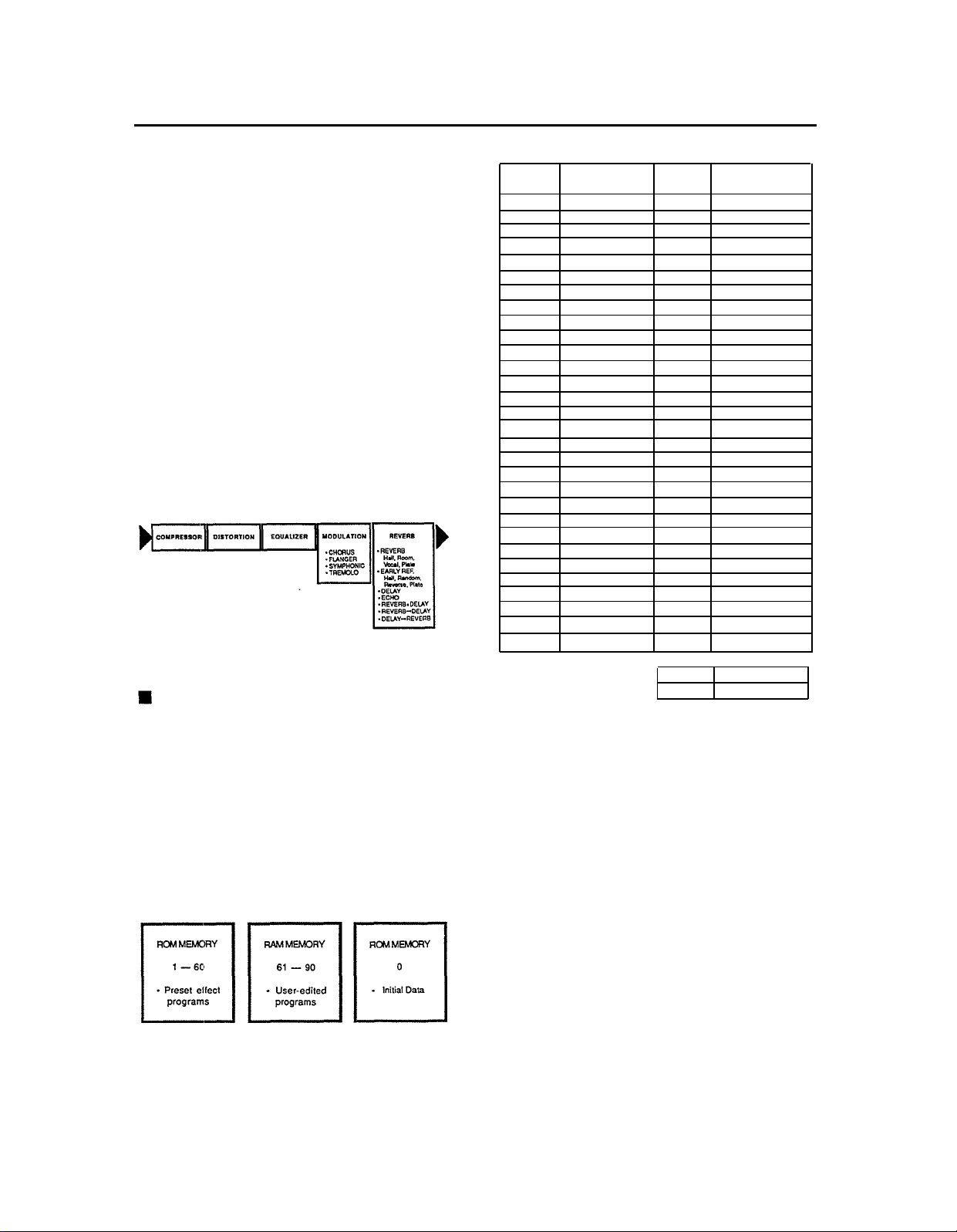
The FX500 SIMUL-EFFECT PROCESSOR is a highperformance digital signal processor intended for use with
electric guitars, electronic keyboards or other instruments.
lt employs leading-edge Yamaha digital signal processing
technology to provide a “chain” of up to six independent
effects that can be independently controlled to produce
precisely the required overall sound. As shown below, the
FX500 includes five effect (compressor, distortion,
equalizer, modulation and reverb) stages. Stages can be
turned on or off as required, and the order of the
modulation and reverb stages can be reversed. The
compressor. distortion and equalizer stages are basically
single-function processors. The modulation and reverb
stages each incorporate a number of separate effects
which can be selected and used as required. Several of
the reverb effects actually combine both delay and reverb,
effectively giving you a total of six effects in the chain!
Each effect has a number of parameters which can be
adjusted to tailor its sound to your specific musical needs.
Program
No.
1
2
3
4
5
6
7
8
9
10
11
12
13
14
15
16
17
18
19
20
21
22
23
24
25
26
27
28
29
30
Program Title
Broad Dist.
Warm Strings
Standard Jazz
Soft Echo
Power Pan
Trad. Dist.
Dark Dist.
Ring Dist.
Metal Overdrive
Echo Dist.
Tight Dist.
Blue Dist.
Fuzz
Slap Dist.
Power Leads
Chasing Leads
Power Stack
Symphonic Dist.
Turbo Drive
Chasing Rhythm
Stereo Dist.
Fusion Dist.
Boogie Room
Buzz Backer
Liquid Dist.
Electric Chords
Clean Repeat
Sweet Swirl
Mild Motion
Pearly Chords
Program
No.
31
32
33
34
35
36
37
38
39
40
41
42
43
44
45
46
47
48
49
50
51
52
53
54
55
56
57
58
59
60
Program Title
Clisp Chords
Sharp Chops
Tremolo
Sweet Flange
Chord-Clouds
Light Symphonic
Clean Acoustic
Acoustic Solo
Lush Strings
Soft Focus
Brass Room
Brass Burst
Trumpet Flange
Brass Energizer
Echo Rhythm
Sumphonic Hall
Horror House
Sitar
Staccato Vibe
Sweep Gate
Monk Akkal
Straight Bass
Slap Bass
Fretless Bass
Trad. Bass
Sax Solo
Vocal Reverb
Drum Gate/Rev
Tight Snare
Rock Drums
Memory Configuration
The FX500 has a total of 91 memory locations. Memory
locations 1 through 60 are ROM (Read Only Memory)
containing 60 pre-programmed effects that you can simply
select and use. Memory locations 61 through 90 are RAM
(Random Access Memory), and can be used to store
original effect programs that you create by editing the
presets. The 30 RAM memory locations (61 — 90)
originally contain a selected group of the preset programs.
The last memory location
contains “initialized data” that can be used as a basis for
creating your own original effects programs from scratch.
— memory location number 0 —
User Programs
61 - 90
Initial Data
0
n
MIDI Control
For further versatility and smooth integration with MIDIbased music systems, the FX500 offers broad MIDI control
capabilities. Any of its 90 memory locations may be
directly selected from a remote MIDI device such as a
keyboard or MIDI foot controller *. lt is also possible to
directly control up to two different effect parameters
simultaneously in real time. This means that two MIDI
controllers (a MODULATION WHEEL and DATA ENTRY
slider on a keyboard, for example) could be used to
control, say, the modulation depth of the flanger effects
and the reverb time of a reverb effect in real time as you
play! Any two MIDI controllers can be assigned to any two
effect parameters (See “MIDI Parameter Control: Control
Change 1 Table Edit and Control Change 2 Table Edit” on
page 20 for operational details).
• Extensive MIDI control is also possible with the MFC1
MIDI Foot Controller. Consult the MFC1 operation
Manual for details.
4
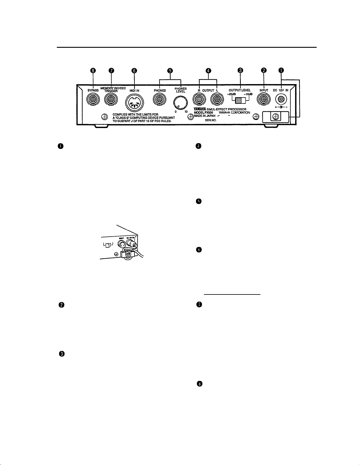
3. Connections: Basic System Setup
DC 12V IN Jack and Cable Clip
The DC output cable from the supplied AC Adaptor
should be connected here. When connecting the power
supply, make sure that the FX500 POWER switch is in
the OFF position (extended).
Plug the AC adaptor output cable into the DC 12V IN
jack, and finally the adaptor’s AC plug into a convenient
AC wall outlet. The cable clip located immediately
below the DC 12V IN jack helps to prevent accidental
unplugging of the power supply during use. Wrap the
DC cable firmly around the clip a few centimeters from
the plug end.
CAUTION!
Do not attempt to use a different AC adaptor to power
the FX500. The use of an incompatible adaptor may
cause irreparable damage to the FX500, and might
pose a serious shock hazard!
INPUT Jack
This jack duplicates the function of the front-panel
INPUT jack described in the following section. It is
important to note, however, that only one of the INPUT
jacks can be used at a time. lf plugs are inserted into
both the front and rear-panel inputs, the front-panel
input jack takes priority.
OUTPUT LEVEL Selector
This switch is used to match the output level of the
FX500 to the input sensitivity of the amplifier, mixing
console or other device it is feeding. For compatibility
with standard line-level inputs the -10 dB setting
should be appropriate, while the -20 dB setting should
be used when the FX500 is connected to a high-
sensitivity input-the input of a guitar amplifier, for
example.
OUTPUT R and OUTPUT L Jacks
These are the main stereo outputs from the FX500. We
recommend using both outputs and connecting them to
the corresponding right and left channels of a stereo
sound system, since the full impact of many of the
FX500 effects can only be appreciated in stereo. lf,
however, only a mono sound system is available, use
either the OUTPUT R or OUTPUT L jack.
PHONES LEVEL Control and PHONES Jack
For private listening or practice when an external
sound system cannot be used, a pair of standard
stereo headphones (with a 1/4” stereo phone plug or
appropriate adaptor plug) can be plugged into the
PHONES jack. The PHONES LEVEL control adjusts
the headphone listening level.
MIDI IN Connector
The MIDI IN connector accepts MIDI signals from an
external MIDI device such as a MIDI foot controller,
keyboard, etc. The FX500 will accept MIDI PROGRAM
CHANGE messages to directly select effect programs,
or MIDI CONTROL CHANGE messages to control
individual effect parameters.
[See page 19 for further details]
MEMORY INC/DEC, TRIGGER (TAP TEMPO DELAY)
Jack
An optional Yamaha FC4 or FC5 Footswitch may be
connected here for convenient foot-controlled selection
of effect programs or "tap tempo delay” control which is
used to set delay time for the delay effects. The
function of the footswitch is determined by the UTILITY
mode Foot Switch Function Select function (page 22).
The range of effect programs that can be selected
when the footswitch is assigned to memory selection is
determined by the UTlLlTY mode Footswitch Memory
Recall Range Edit function (page 23).
BYPASS Jack
An optional Yamaha FC4 or FC5 Footswitch connected
here performs exactly the same function as the frontpanel BYPASS key. Press the footswitch once to
activate the bypass mode, and again to turn bypass off.
5
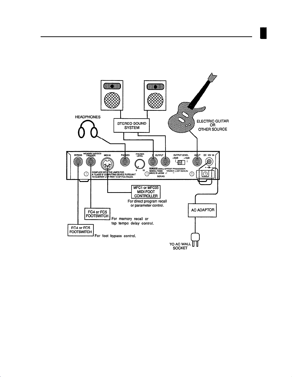
Basic System Configuration
6
4. The Controls: A Quick Operation Guide
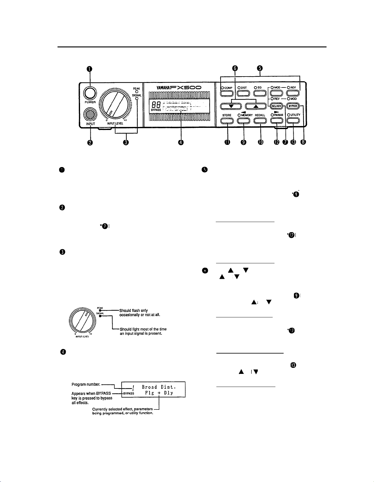
Power Switch
Press once to turn the FX500 on, and a second time to
turn the power off. When the power is turned on, a title
and copyright notice will appear on the display panel for
a few seconds before operation actually begins.
Input Jack
Plug your guitar, keyboard or other signal source in
here or into the duplicate INPUT jack provided on the
rear panel (see INPUT Jack” in the “3. Connec-
tions: Basic System Setup” section). Both jacks are
standard monaural 1/4” phone jacks.
INPUT LEVEL Control with SIGNAL and PEAK
Indicators
For the optimum input level setting, play your source at
the highest level it will be played in actual use. Adjust
the INPUT LEVEL control so that the SIGNAL Indicator
lights most of the time but the PEAK indicator does not
light, or lights only occasionally on brief high-level
peaks.
Liquid Crystal Display Panel
This is the FX500’s main “information center”, providing
all information necessary for effect program selection,
programming and utility control.
COMP, DIST, EQ, MOD and REV Effect Keys
These keys function differently in the MEMORY and
PARAM modes.
•
When the MEMORY mode is selected (i.e. when the
MEMORY key indicator is lit—see
Mode Key”), these keys are used to turn the
corresponding effect stage ON (indicator lit) or OFF
(indicator out).
[See page 10 for further details]
•
When the PARAM mode is selected (i.e. when the
PARAM key indicator is lit—see
Key”),
these
keys select the various parameters
available for editing in the corresponding effect
stage.
[See page 11 for further details]
Arrow(
The
PARAM and UTILITY modes.
•
When the MEMORY mode is selected (i.e. when the
MEMORY key indicator is lit-see"
Mode Key”), the
the desired effect program.
[See page 9 for further details]
•
When the PARAM mode is selected (i.e. when the
•
)and(
) keys
keys function differently in the MEMORY,
and
and
are used to select
PARAM key indicator is lit — see
Key”), they are used to “edit” the selected effect
parameter.
[See page 11 for further details]
When the UTILITY mode is selected (i.e. when the
UTILITY key indicator is lit — see"
and
Key”), the
selected utility function.
[See page 19 for further details]
keys are used to program the
MEMORY
PARAM Mode
MEMORY
PARAM Mode
UTILITY Mode
7

SEL/ASN Key
The SEL/ASN key functions differently in the MEMORY
and
PARAM modes.
When the MEMORY mode is active this key
•
reverses the order of the MOD and REV processing
stages.
[See page 10 for further details]
•
In the PARAM mode, the SEL/ASN key is used to
assign effect parameters for control via external
MIDI controllers.
[Seepage 21 for further details]
BYPASS Key
When the BYPASS key is pressed and “BYPASS”
appears on the display panel, all FX500 effect stages
are completely bypassed and the input signal is fed
directly to the output. Press the BYPASS key a second
time to turn the bypass function off. The rear-panel
BYPASS footswitch jack can also be used for bypass
control (see “
MEMORY Mode Key and lndicator
When the MEMORY key indicator is lit, the FX500
MEMORY mode is active and effect programs (1 — 90)
can be selected and recalled using the
and RECALL key. In the MEMORY mode it is also
possible to turn effect stages ON or OFF using the
COMP, DIST, EQ, MOD and REV keys. The MEMORY
mode can be activated while the PARAM mode is
selected by pressing the MEMORY key. The MEMORY
mode can not be directly selected from the UTILITY
mode by pressing the MEMORY key. The UTlLlTY
mode must first be exited by pressing the UTILITY key
several times or holding it down (approximately 1
second) until the UTILITY key indicator goes out.
[See page 9 for further details]
BYPASS Jack" on page 5).
and
keys
PARAM Mode Key and lndicator
The PARAM key selects the PARAM (parameter) mode
in which the individual parameters for each effect stage
can be edited as required. The PARAM key indicator
lights when the PARAM mode is active. The PARAM
mode can not be directly selected from the UTlLlTY
mode by pressing the PARAM key. The UTILITY mode
must first be exited by pressing the UTILITY key
several times or holding it down (approximately 1
second) until the UTILITY key indicator goes out.
[See page 11 for further details]
UTILITY Mode Key and lndicator
Pressing this key activates the UTlLlTY mode, allowing
access to 7 different utility functions:
• Program Title Edit [Page 19]
• MIDI Setup [Page 20]
• Program Change Table Edit [Page 20]
• Control Change 1 Table Edit [Page 21]
• Control Change 2 Table Edit [Page 21]
• Foot Switch Function Select [Page 22]
•
Foot Switch Memory Recall Range Edit [Page 23]
The UTILITY key LED lights when the UTlLlTY mode is
active. Each time the UTlLlTY key is pressed the next
function on the utility “list” is selected. The mode that
was active before the UTILITY key was pressed
(MEMORY or PARAM) is selected following the last
function on the utility list. The UTILITY mode can also
be exited by pressing the UTILITY key several times or
holding it down (approximately 1 second) until the
UTILITY key indicator goes out.
RECALL Key
After using the
program while in the MEMORY mode, the RECALL key
is pressed to actually recall and activate the selected
program.
[See page 9 for further details]
STORE Key
After editing any of the effect programs, the new
program can be stored in any of the FX500’s RAM
memory locations (61 through 90) for later recall and
use. The STORE key is used to store edited data to a
RAM memory location.
[See page 12 for further details]
and
keys to select a disired effect
8
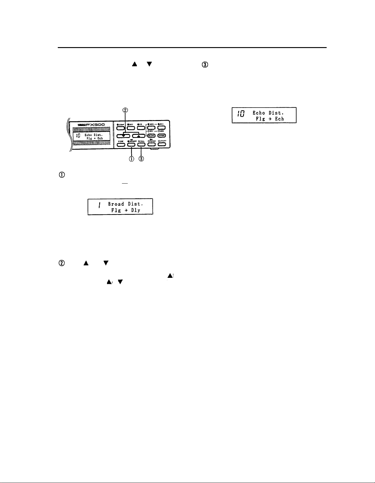
5. The MEMORY Mode: Selecting Effect Programs
In the FX500 MEMORY mode, the
used to select individual effect programs. When a new
program number is selected, its number will flash on the
display and its title will appear on the upper line. Press the
RECALL key to actually recall and activate the selected
program.
lf the MEMORY mode is not already selected (i.e. if the
MEMORY key indicator is not lit), press the MEMORY
key to select the MEMORY mode.
The MEMORY mode can not be directly selected from
the UTILITY mode by pressing the MEMORY key. The
UTILITY mode must first be exited by pressing several
times or holding (about one second) the UTILITY key
until the UTILITY key indicator goes out.
and
keys can be
The number of the selected effect program should now
be flashing on the display, indicating that the program
has been selected but has not yet been recalled (the
previous effect program is still active). Press the
RECALL key to actually recall and activate the selected
program. The program number will stop flashing.
Use the
desired effect program (in this example we go to
program number 10 from number 1, so only the
is used). Press the
highest or lowest numbered program, or hold either key
down for continuous scrolling in the corresponding
direction. Faster scrolling is achieved by pressing the
opposite arrow key while holding the arrow key
corresponding to the direction of scrolling.
and/or
keys to select the number of the
key
or
key briefly to select the next
9
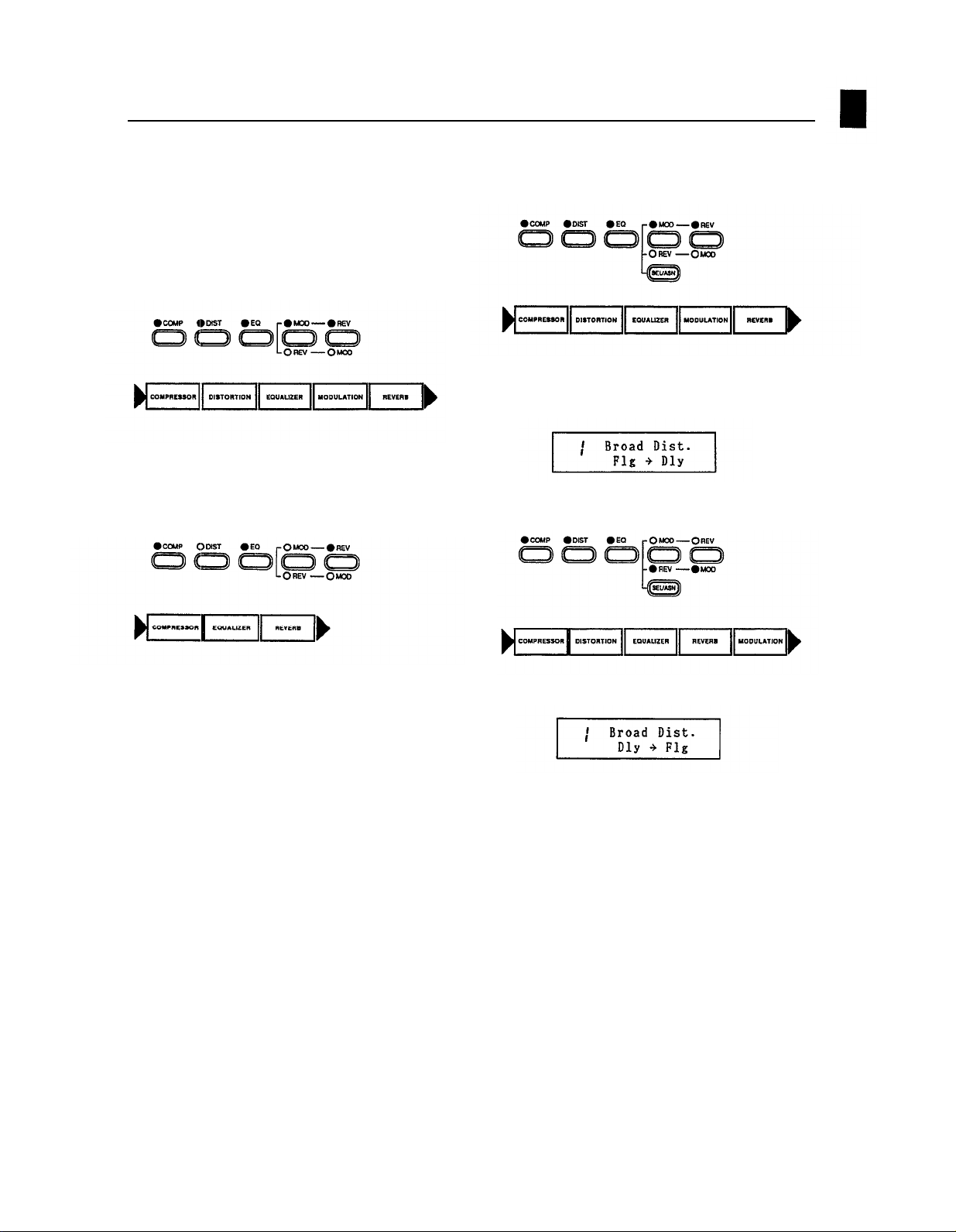
6. Effect Processor Selection
In the MEMORY mode the FX500 effect stages can be
individually turned ON or OFF by using the COMP, DIST,
EQ, MOD and REV keys. Pressing any of these keys
alternately turns the corresponding effect stage ON
(indicator lit) or OFF (indicator out). When a stage is turned
OFF, it is bypassed and the previous active stage is
connected directly to the following active stage. lf all
stages are ON, the effect chain is as shown below:
lf, however, you only wanted to use the compressor,
equalizer and reverb stages, you could press the DIST and
MOD keys to turn the stages OFF, resulting in the effect
chain shown below:
This is the normal order of the MOD and REV effect
stages:
The current order of the selected effects in the MOD and
REV stages is also shown on the bottom line of the display
(“MOD - REV” in this case).
Press the SEL/ASN key to reverse this order.
NOTE:
The ON/OFF status of each effect is stored to the
RAM memory along with all other effect data when
a STORE operation is performed (see “Memory
Store Operation” on page 12).
n
Reversing the Order of the
Modulation & Reverb Stages
Normally, the last two effects in the FX500 effect chain are
a modulation type and reverb type, in that order. By
pressing the SEL/ASN key while in the MEMORY mode,
however, this order may be reversed. The order of the
MOD and REV effect stages is shown on the bottom line of
the LCD, and the LEDs associated with the MOD and REV
keys will light to show the selected order:
•
MOD — • REV — • MOD.
The new MOD/REV order is also shown on the display.
The ability to reverse the order of the modulation and
reverb stages is important because it gives you choice of
applying reverb/delay to the already-modulated signal, or
applying modulation to the reverb/delay signal. The
difference in sound can be quite significant.
NOTE:
The selected order of the MOD and REV effect
stages is stored to the RAM memory along with all
other effect data when a STORE operation is
performed (see “Memory Store Operation” on
page
12).
10
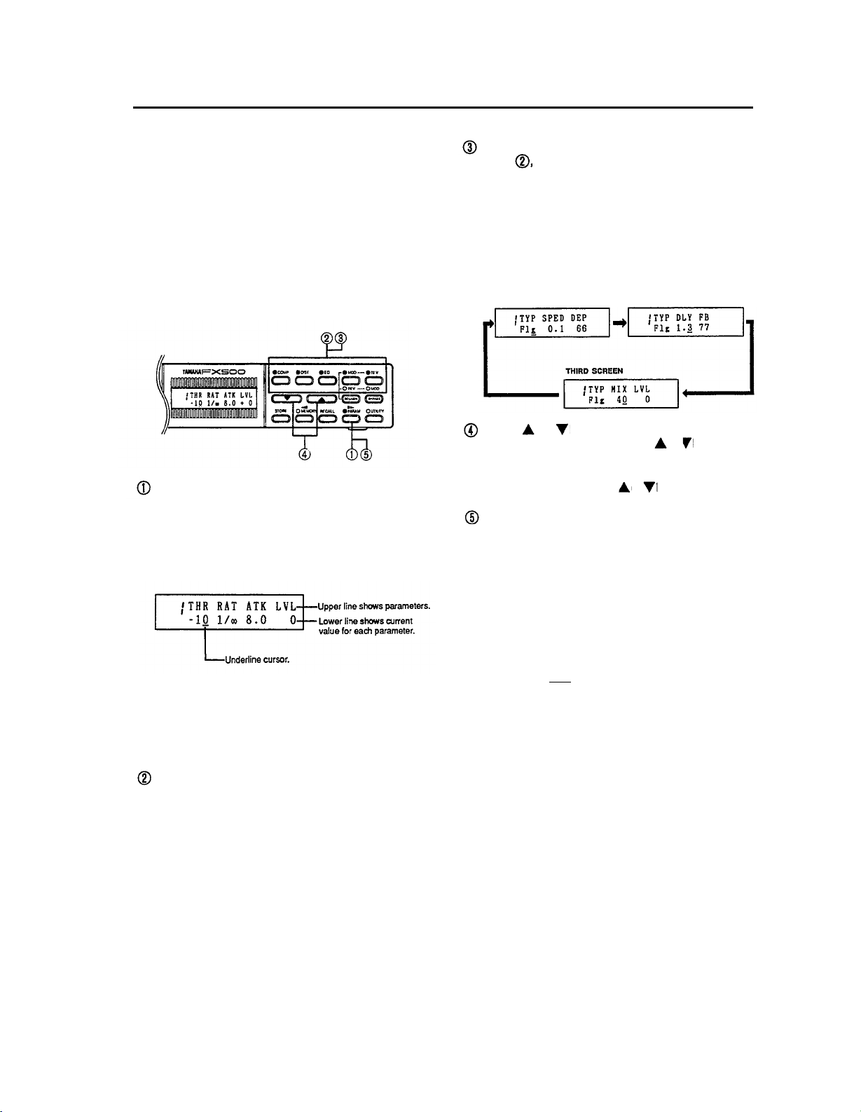
7. The Parameter Mode: Editing the Effect Programs
The parameter mode provides access to several important
parameters for each effect, allowing you to change the
sound of each effect over a broad range to suit your
specific requirements. Once the parameters for each effect
stage have been programmed and fine-tuned to provide
exactly the sound you want, the entire effect program can
be stored into one of the FX500’s RAM memory locations
for later recall and use.
n
Editing Parameter Data
The parameter mode is entered by pressing the
PARAM key. The parameter abbreviations are
displayed on the upper line of the LCD, and the
corresponding data values are shown on the bottom
line (the parameters will be described in detail in the
following sections).
The PARAM mode can not be directly selected from the
UTlLlTY mode by pressing the PARAM key. The
UTILITY mode must first be exited by pressing several
times or holding (about one second) the UTILITY key
until the UTILITY key indicator goes out.
Press the COMP, DIST, EQ, MOD or REV key to select
the effect you wish to edit.
Press the selected effect key (i.e. the key you pressed
in step , above) to move the cursor to the parameter
to be edited. Each time the effect key is pressed the
cursor moves one parameter to the right. In many
effects, two or three parameter screens are required,
so the next screen will appear when the cursor is
moved past the last parameter on each screen. The
first screen is re-selected after the last parameter on
the last screen. The modulation stage flanger effect, for
example, has the following three parameter screens:
FIRST SCREEN
Use the and keys to adjust the value of the
selected parameter. lf you hold the
will scroll continuously in the specified direction. The
data will scroll faster if you press the opposite arrow
key while holding either the
The effect selected for editing can be turned ON or
OFF by pressing the PARAM key, so you can easily
compare the direct and processed sound.
NOTE:
To prevent accidental loss of edited data, the
FX500 responds with a confirmation display —
“RECALL OK ?” —
while editing in the PARAM mode. lf you actually
intend to recall the original (pre-edit) effect, press
the RECALL key a second time. lf you do not
want to carry out the recall operation, simply press
any key other
•
Assigning MIDI CONTROLLERS to Effect
than the RECALL key.
SECOND SCREEN
or
key the data
key.
or
if you press the RECALL key
Parameters
lf the SEL/ASN key is pressed in the PARAM mode, it
becomes possible to assign external MIDI CONTROLLERS to diectly control effect parameters. Refer to
“Assigning CONTROLLER 1 and CONTROLLER 2 to
Specific Effects” on page 21.
11
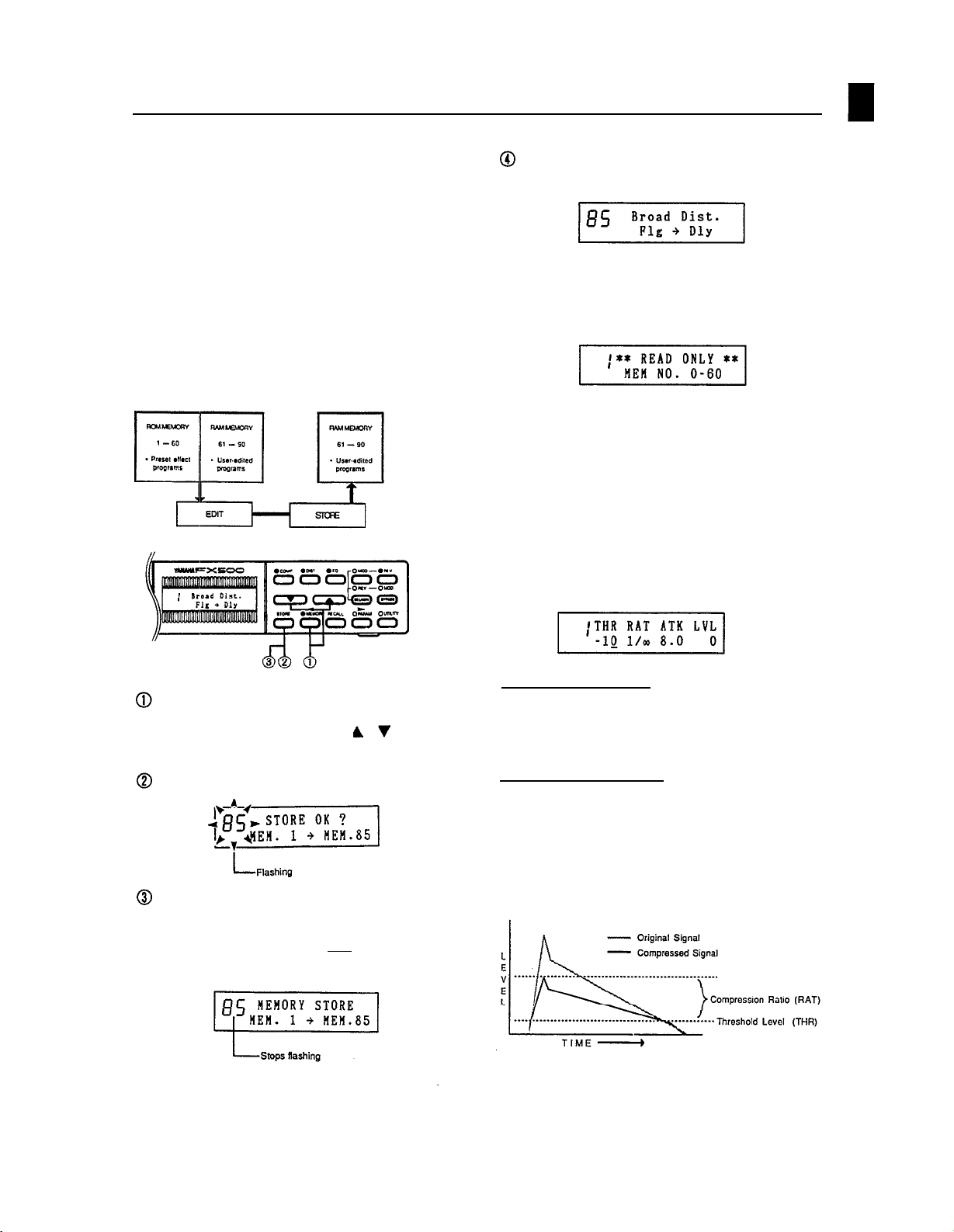
•
Memory Store Operation
An edited effect program can be stored in any memory
location within the FX500’s RAM memory area (61 through
90). Original effect programs stored in this way can be
selected and used in exactly the same way as the preset
effect programs. The ON/OFF status of each effect, the
selected order of the MOD and REV stages and MIDI
CONTROLLER assignments are stored along with all other
parameter data. The UTILITY mode TlTLE EDlT function
can be used to create new titles for your original effect
programs after you have stored them in RAM memory.
(See “Program Title Edit” on page 19)
When the store operation is complete, the memory
location stored to will be selected automatically.
NOTE:
lf you attempt to use the STORE function while a
ROM memory location is selected, the following
display will appear and the store operation will be
aborted.
n
COMPRESSOR (COMP)
The compressor effect stage produces sustain or simple
“smoothing” by compressing the signal so that high levels
are suppressed while low levels are effectively boosted.
The use of compression before other effect stages is
particularly effective because it limits the signal to a
dynamic range that results in improved sound with the
subsequent effects.
After editing the parameters to create the desired
effect, select the MEMORY mode and select the RAM
memory location (61
which you wish to store the edited data.
Press the STORE key.
Press the STORE key again. The following display will
appear for a few seconds while the store operation is in
progress. lf you decide not to go ahead with the store
operation, simply press any key other
key.
— 90) with the
key to
or
than the STORE
THR (Threshold: -60 — 0 dB)
Sets the compressor threshold level. signal levels
exceeding the threshold level will be compressed while
those below the threshold level will be unaffected.
RAT (Ratio: 1/2,1/4,1/8, 1/00)
This parameter sets the degree of compression. A
compression ratio of 1/2, for example, compresses signals
above the threshold level to one-half their original
amplitude. A setting of 1/00 produces almost total
compression, producing the same signal level for all
signals above the threshold level. This yields the greatest
degree of sustain.
12
 Loading...