

Yamaha FJR1300 User Manual

OWNER’S MANUAL
FJR1300
5JW-28199-E0


EAU03338
INTRODUCTION
Welcome to the Yamaha world of motorcycling!
As the owner of an FJR1300, you are benefiting from Yamaha’s vast experience and
newest technology regarding the design and manufacture of high-quality products,
which have earned Yamaha a reputation for dependability.
Please take the time to read this manual thoroughly, so as to enjoy all advantages of
your FJR1300. The owner’s manual does not only instruct you in how to operate,
inspect and maintain your motorcycle, but also in how to safeguard yourself and others from trouble and injury.
In addition, the many tips given in this manual will help keep your motorcycle in the
best possible condition. If you have any further questions, do not hesitate to contact
your Yamaha dealer.
The Yamaha team wishes you many safe and pleasant rides. So, remember to put
safety first!
IMPORTANT MANUAL INFORMATION
Particularly important information is distinguished in this manual by the following notations:
The Safety Alert Symbol means ATTENTION! BECOME ALERT! YOUR SAFETY IS
INVOLVED!
EAU00005
WARNING
CAUTION:
NOTE:
Failure to follow WARNING instructions could result in severe injury or death to the
motorcycle operator, a bystander, or a person inspecting or repairing the
motorcycle.
A CAUTION indicates special precautions that must be taken to avoid damage to the
motorcycle.
A NOTE provides key information to make procedures easier or clearer.
NOTE:
_
This manual should be considered a permanent part of this motorcycle and should remain
●
with it even if the motorcycle is subsequently sold.
Yamaha continually seeks advancements in product design and quality. Therefore, while
●
this manual contains the most current product information available at the time of printing,
there may be minor discrepancies between your motorcycle and this manual. If you have
any questions concerning this manual, please consult your Yamaha dealer.
_
IMPORTANT MANUAL INFORMATION
EW000002
WARNING
_
PLEASE READ THIS MANUAL CAREFULLY AND COMPLETELY BEFORE OPERATING
THIS MOTORCYCLE.
_
IMPORTANT MANUAL INFORMATION
FJR1300
OWNER’S MANUAL
© 2001 by Yamaha Motor Co., Ltd.
1st Edition, December 2000
All rights reserved.
Any reprinting or unauthorized use
without the written permission of
Yamaha Motor Co., Ltd.
is expressly prohibited.
Printed in Japan.
EAU03337
EAU00009
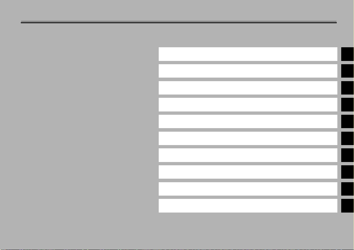
TABLE OF CONTENTS
1 GIVE SAFETY THE RIGHT OF WAY
2 DESCRIPTION
3 INSTRUMENT AND CONTROL FUNCTIONS
4 PRE-OPERATION CHECKS
5 OPERATION AND IMPORTANT RIDING POINTS
6 PERIODIC MAINTENANCE AND MINOR REPAIR
7 MOTORCYCLE CARE AND STORAGE
8 SPECIFICATIONS
9 CONSUMER INFORMATION
INDEX
1
2
3
4
5
6
7
8
9

GIVE SAFETY THE RIGHT OF WAY
GIVE SAFETY THE RIGHT OF WAY ......................... ... ... ... ... .... ... ... . 1-1
1
1-
GIVE SAFETY THE RIGHT OF WAY
EAU00021
Motorcycles are fascinating vehicles, which can give you an unsurpassed feeling of power and
freedom. However, they also impose certain limits, which you must accept; even the best motorcycle
does not ignore the laws of physics.
1
Regular care and maintenance are essential for preserving value and operating condition of your
motorcycle. Moreover, what is true for the motorcycle is also true for the rider: good performance
depends on being in good shape. Riding under the influence of medication, drugs and alcohol is, of
course, out of the question. Motor cycle riders—more t han car drivers—must always be at their ment al
and physical best. Under the influence of even small amounts of alcohol, there is a tendency to take
dangerous risks.
Protective clothing is as essential for the motorcycle rider as seat belts are for car drivers and
passengers. Always wear a complete motorcycle suit (whether made of leather or tear-resistant
synthetic materials with protectors), sturdy boots, motorcycle gloves and a properly fitting helmet.
Optimum protective wear, however, should not encourage carelessness. Although full-coverage
helmets and suits, in particular, create an illusion of total safety and protection, motorcyclists will
always be vulnerable. Riders who lack critical self-control run the risk of going too fast and are apt to
take chances. This is even more dangerous in wet weather. The good motorcyclist rides safely,
predictably and defensively—avoiding all dangers, including those caused by others.
Enjoy your ride!
1-1

DESCRIPTION
Left view............................................................................................. 2-1
Right view...........................................................................................2-2
Controls and instruments ............................................ ... ... .................2-3
2

2-
DESCRIPTION
Left view
2
EAU00026
1.Fuse box (page 6-31)
2.Front fork spring preload adjusting bolt (page 3-12)
3.Front fork rebound damping force
adjusting knob (page 3-13)
4.Engine oil filler cap (page 6-10)
5.Owner’s tool kit (page 6-1)
6.Rider seat (page 3-11)
7.Passenger seat (page 3-11)
8.Carrier
9.Final gear oil filler bolt (page 6-12)
10.Final gear oil drain bolt (page 6-12)
11.Shock absorber assembly rebound
damping force adjusting knob (page 3-15)
12.Shock absorber assembly spring preload
adjusting lever (page 3-14)
13.Air filter element (page 6-15)
14.Shift pedal (page 3-7)
15.Engine oil filter cartridge (page 6-10)
16.Engine oil level check window (page 6-10)
2-1
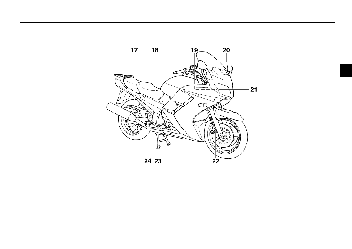
Right view
17.Passenger footrest
18.Coolant reservoir (page 6-13)
19.Battery (page 6-30)
20.Windshield
21.Main fuse and fuel injection system fuse (page 6-31)
22.Front fork compression damping force
adjusting screw (page 3-13)
23.Brake pedal (page 3-8)
24.Rider footrest
DESCRIPTION
2
2-2
DESCRIPTION
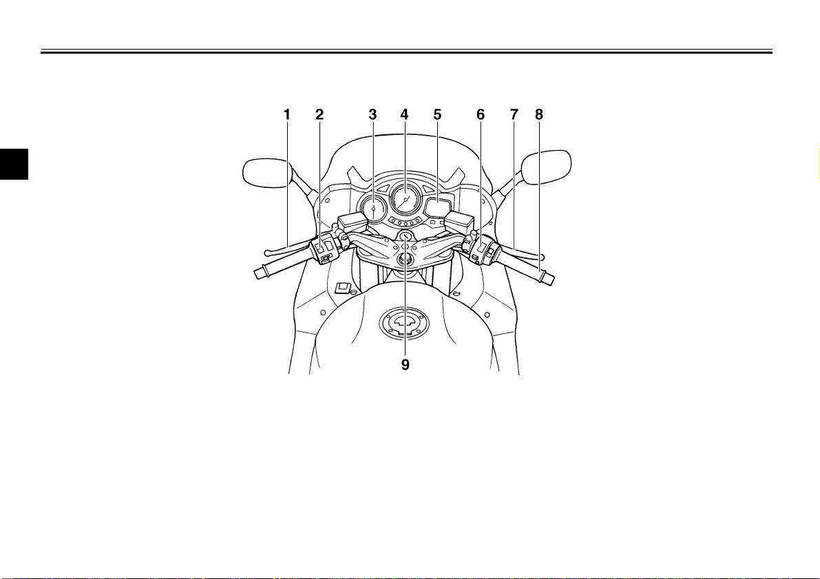
Controls and instruments
2
1.Clutch lever (page 3-7)
2.Left handlebar switches (page 3-5)
3.Tachometer (page 3-3)
4.Speedometer (page 3-3)
5.Multi-function display (page 3-4)
6.Right handlebar switches (page 3-6)
7.Brake lever (page 3-8)
8.Throttle grip (page 6-17)
9.Main switch/steering lock (page 3-1)
2-3

INSTRUMENT AND CONTROL FUNCTIONS
Main switch/steering lock ........................................... ... .................... 3-1
Indicator and warning lights ............................................................. 3-2
Speedometer ....................... ................ ................ ................ ............. . 3 -3
Tachometer .......................................................................................3-3
Multi-function display ......................................................................... 3-4
Handlebar switches ........................................................................... 3-5
Clutch lever ..... .... ... ... ... .... .......................................... ... .................... 3-7
Shift pedal .........................................................................................3-7
Brake lever ........................................................................................3-8
Brake pedal .......................................................................................3-8
Anti-theft alarm (optional) .................................................................. 3-9
Fuel tank cap ................ .... ... ... ... .......................................... ... .... .......3-9
Fuel ................................................................................................. 3-10
Fuel tank breather hose ................................................... ... ............3-10
Seats.............................................. ... ... .......................................... .. 3-11
Storage compartment .....................................................................3-12
Adjusting the front fork . .... ... ... .......................................... ... ... .... .....3-12
Adjusting the shock absorber assembly .............................. ... .... ... .. 3-14
Matching the front and rear suspension settings ............................3-16
Locks for the optional side cases and travel trunk ........................... 3 - 17
Sidestand ........................................................................................ 3-17
Ignition circuit cut-off system ........................................................... 3-18
3
3-
WARNING
INSTRUMENT AND CONTROL FUNCTIONS
3
EAU00029
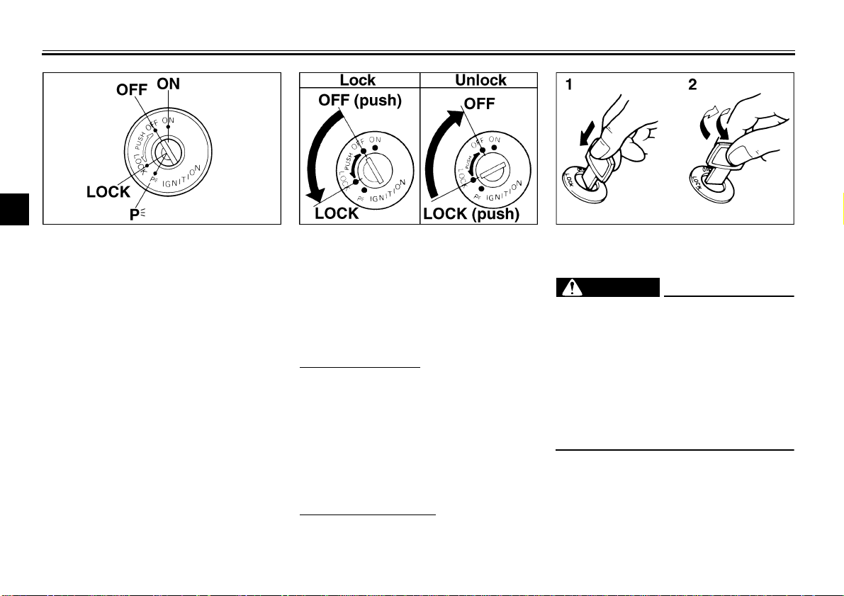
Main switch/steering lock
The main switch/steering lock controls
the ignition and lighting systems, and is
used to lock the steering. The various
LOCK
The steering is locked, and all electrical
systems are off. The key can be removed.
positions are described below.
To lock the steering
EAU00036
ON
All electrical systems are supplied with
power, and the engine can be started.
The key cannot be removed.
EAU00038
1. Turn the handlebars all the way to
the left.
2. Push the key in from the “OFF” position, and then turn it to “LOCK”
while still pushing it.
3. Remove the key.
OFF
All electrical systems are off. The key
can be removed.
To unlock the steering
Push the key in, and then turn it to
“OFF” while still pushing it.
EAU00040
EAU00027
1. Push.
2. Turn.
EW000016
_
Never turn the key to “OFF” or
“LOCK” while the motorcycle is
moving, otherwise the electrical
systems will be switched off, which
may result in loss of control or an
accident. Make sure that the motorcycle is stopped before turning the
key to “OFF” or “LOCK”.
_
3-1
INSTRUMENT AND CONTROL FUNCTIONS
NOTE:
EAU01237
(Parking)
The steering is locked, and the taillights
and auxiliary lights are on, but all other
electrical systems are off. The key can
be removed.
The steering must be locked before the
key can be turned to “ ”.
ECA00043
CAUTION:
_
Do not use the parking position for
an extended length of time, otherwise the battery may discharge.
_
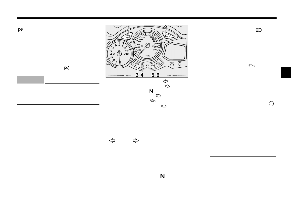
1. Left turn signal indicator light “ ”
2. Right turn signal indicator light “ ”
3. Neutral indicator light “ ”
4. High beam indicator light “ ”
5. Oil level warning light “ ”
6. Engine trouble warning light “ ”
EAU03034
Indicator and warning lights
EAU03299*
Turn signal indicator lights
“” and “”
The corresponding indicator light flashes when the turn signal switch is
pushed to the left or right.
EAU00061
Neutral indicator light “ ”
This indicator light comes on when the
transmission is in the neutral position.
3-2
EAU00063
High beam indicator light “ ”
This indicator light comes on when the
high beam of the headlight is switched
on.
EAU03201
Oil level warning light “ ”
This warning light comes on when the
engine oil level is low.
The electrical circuit of the warning light
can be checked according to the following procedure.
1. Set the engine stop switch to “ ”
and turn the key to “ON”.
2. Shift the transmission into the neutral position or pull the clutch lever.
3. Push the start switch. If the warning
light does not come on while pushing the start switch, have a Yamaha
dealer check the electrical circuit.
_
Even if the oil level is sufficient, the
warning light may flicker when riding on
a slope or during sudden acceleration
or deceleration, but this is not a malfunction.
_
3
INSTRUMENT AND CONTROL FUNCTIONS
CAUTION:
3
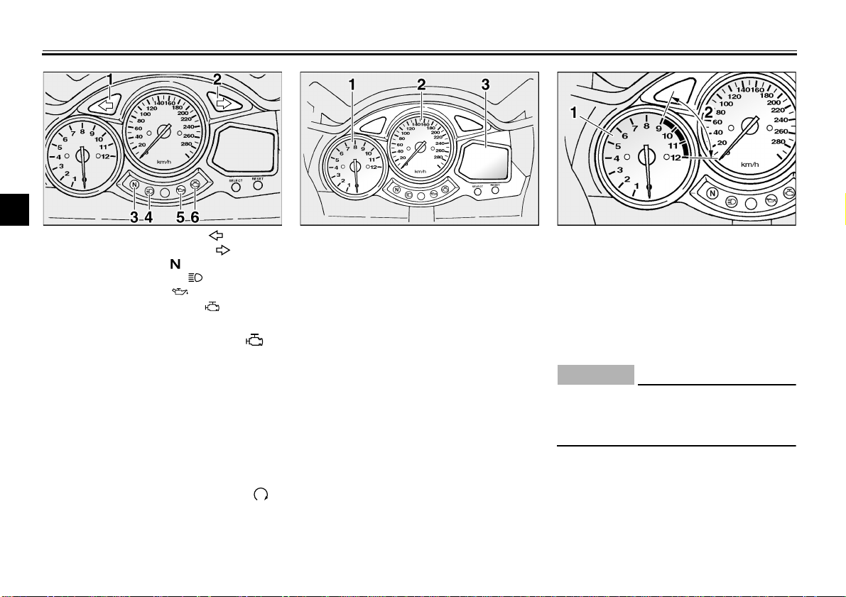
1. Left turn signal indicator light “ ”
2. Right turn signal indicator light “ ”
3. Neutral indicator light “ ”
4. High beam indicator light “ ”
5. Oil level warning light “ ”
6. Engine trouble warning light “ ”
Engine trouble warning light “ ”
This warning light comes on or flashes
when an electrical circuit monitoring
the engine is defective. When this occurs, have the Yamaha dealer check
the self-diagnosis system.
The electrical circuit of the warning light
can be checked according to the following procedure.
1. Set the engine stop switch to “ ”.
2. Turn the key to “ON”. If the warning light does not come on, have a
Yamaha dealer check the electrical circuit.
EAU03192
1. Tachometer
2. Speedometer
3. Multi-function display
EAU04031
Speedometer
The speedometer shows the riding
speed.
3-3
1. Tachometer
2. Tachometer red zone
EAU00101
Tachometer
The electric tachometer allows the rider
to monitor the engine speed and keep it
within the ideal power range.
EC000003
_
Do not operate the engine in the tachometer red zone.
Red zone: 9,000 r/min and above
_
INSTRUMENT AND CONTROL FUNCTIONS
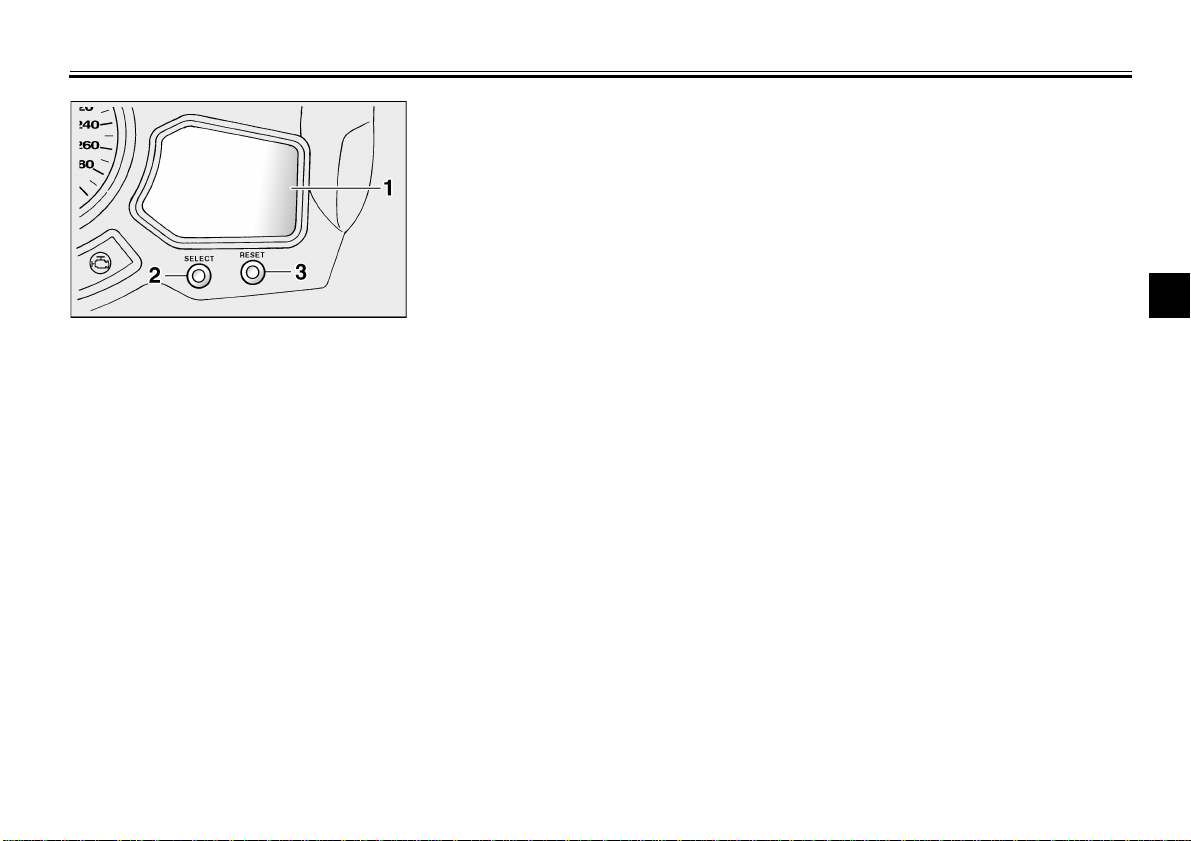
1. Multi-function display
2. “SELECT” button
3. “RESET” button
EAU04066
Multi-function display
The multi-function display is equipped
with the following:
a fuel gauge
●
a coolant temperature gauge
●
an odometer (which shows the to-
●
tal distance traveled)
two tripmeters (which show the
●
distance traveled since they were
last set to zero)
a fuel reserve tripmeter (which
●
shows the distance traveled on the
fuel reserve)
a self diagnosis device
●
a clock
●
Odometer and tripmeter modes
Pushing the “SELECT” button switches
the display between the odometer
mode “ODO” and the tripmeter modes
“TRIP” in the following order:
ODO → TRIP (top) → TRIP (bottom)
ODO
→
When approximately 5 L of fuel remains in the fuel tank, the display will
automatically change to the fuel reserve tripmeter mode “TRIP F” and
start counting the distance traveled
from that point. In that case, pushing
the “SELECT” button switches the display between the various tripmeter and
odometer modes in the following order:
TRIP F → TRIP (top) → TRIP (bottom)
ODO → TRIP F
→
To reset a tripmeter, select it by pushing the “SELECT” button, and then
push the “RESET” button for at least
one second. If you do not reset the fuel
reserve tripmeter manually, it will reset
itself automatically and the display will
return to the prior mode after refueling
and traveling 5 km.
Self diagnosis device
This model is equipped with a self-diagnosis device for various electrical circuits.
If any of those circuits are defective,
the multi-function display will indicate a
two-digit error code (e.g., 11, 12, 13).
If the multi-function display indicates
such an error code, note the code number, and then have a Yamaha dealer
check the motorcycle.
3
3-4
INSTRUMENT AND CONTROL FUNCTIONS
NOTE:
CAUTION:
_
If the multi-function display indicates an error code, the motorcycle
should be checked as soon as possible in order to avoid engine damage.
_
3
Clock mode
To set the clock:
1. Push the “SELECT” button and
“RESET” button together for at
least two seconds.
2. When the hour digits start flashing,
push the “RESET” button to set
the hours.
3. Push the “SELECT” button, and
the minute digits will start flashing.
4. Push the “RESET” button to set
the minutes.
5. Push the “SELECT” button and
then release it to start the clock.
ECA00090
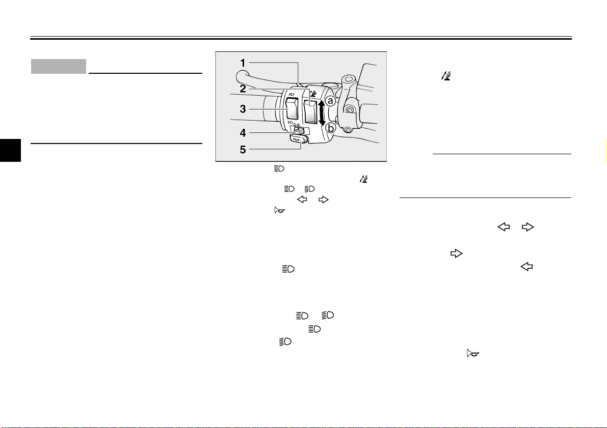
1. Pass switch “ ”
2. Windshield position adjusting switch “ ”
3. Dimmer switch “ / ”
4. Turn signal switch “ / ”
5. Horn switch “ ”
EAU00118
Handlebar switches
EAU00119
Pass switch “ ”
Press this switch to flash the headlight.
EAU03888
Dimmer switch “ / ”
Set this switch to “ ” for the high
beam and to “ ” for the low beam.
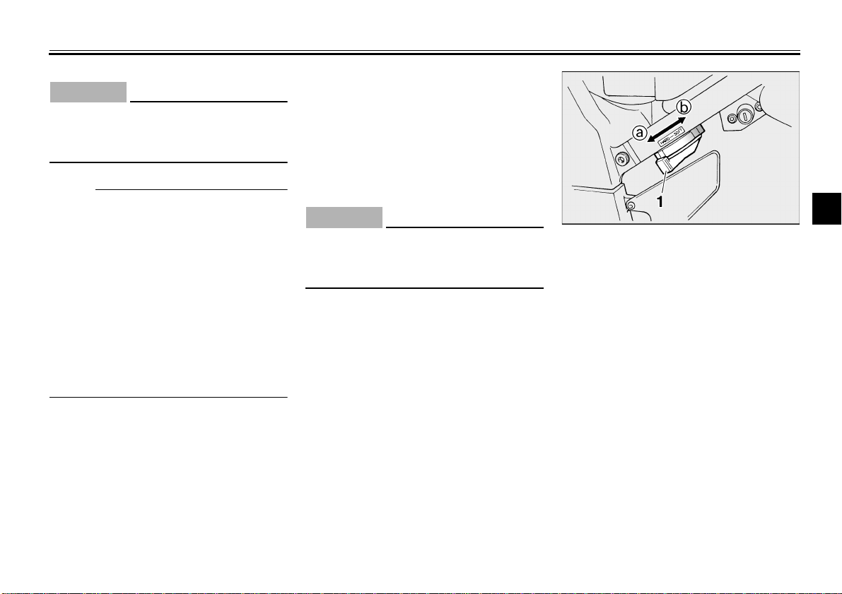
EAU04077
Windshield position adjusting
switch “ ”
To move the windshield up, push this
switch in direction a. To move the
windshield down, push the switch in direction b.
_
When the engine is turned off, the
windshield will automatically return to
the lowest position.
_
EAU03889
Turn signal switch “ / ”
To signal a right-hand turn, push this
switch to “ ”. To signal a left-hand
turn, push this switch to “ ”. When
released, the switch returns to the center position. To cancel the turn signal
lights, push the switch in after it has returned to the center position.
EAU00129
Horn switch “ ”
Press this switch to sound the horn.
3-5
INSTRUMENT AND CONTROL FUNCTIONS
CAUTION:
EAU00143
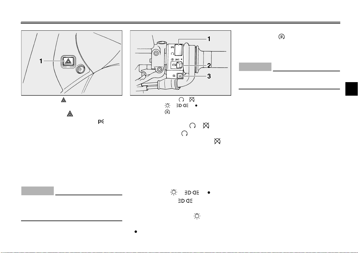
Start switch “ ”
Push this switch to crank the engine
with the starter.
EC000005
_
See page 5-1 for starting instructions prior to starting the engine.
_
3
1. Hazard switch “ ” 1. Engine stop switch “ / ”
Hazard switch “ ”
With the key in the “ON” or “ ” position, use this switch to turn on the hazard light (simultaneous flashing of all
turn signal lights).
The hazard light is used in case of an
emergency or to warn other drivers
when your motorcycle is stopped
where it might be a traffic hazard.
CAUTION:
_
Do not use the hazard light for an extended length of time, otherwise the
battery may discharge.
_
EAU03826
EC000006
2. Light switch “ / / ”
3. Start switch “ ”
EAU03890
Engine stop switch “ / ”
Set this switch to “ ” before starting
the engine. Set this switch to “ ” to
stop the engine in case of an emergency, such as when the motorcycle overturns or when the throttle cable is
stuck.
EAU03898
Light switch “ / / ”
Set this switch to “ ” to turn on the
auxiliary light, meter lighting and taillight. Set the switch to “ ” to turn on
the headlight also. Set the switch to
“ ” to turn off all the lights.
3-6
INSTRUMENT AND CONTROL FUNCTIONS
EAU00153
Clutch lever
The clutch lever is located at the left
handlebar grip. To disengage the
clutch, pull the lever toward the handlebar grip. To engage the clutch, release
the lever. The lever should be pulled
rapidly and released slowly for smooth
3
clutch operation.
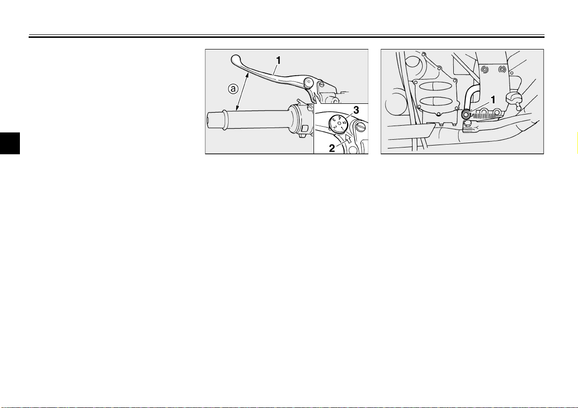
1. Clutch lever
2. Arrow mark
3. Clutch lever position adjusting dial
a. Distance between clutch lever and handlebar
grip
The clutch lever is equipped with a
clutch lever position adjusting dial. To
adjust the distance between the clutch
lever and the handlebar grip, turn the
adjusting dial while holding the lever
pushed away from the handlebar grip.
Make sure that the appropriate setting
on the adjusting dial is aligned with the
arrow mark on the clutch lever.
The clutch lever is equipped with a
clutch switch, which is part of the ignition circuit cut-off system. (See
page 3-18 for an explanation of the ignition circuit cut-off system.)
1. Shift pedal
EAU00157
Shift pedal
The shift pedal is located on the left
side of the engine and is used in combination with the clutch lever when
shifting the gears of the 5-speed constant-mesh transmission equipped on
this motorcycle.
3-7
EAU00161
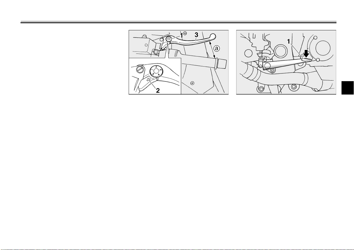
Brake lever
The brake lever is located at the right
handlebar grip. To apply the front
brake, pull the lever toward the handlebar grip.
INSTRUMENT AND CONTROL FUNCTIONS
3
1. Brake lever position adjusting dial
2. Arrow mark
3. Brake lever
a. Distance between brake lever and handlebar
grip
The brake lever is equipped with a position adjusting dial. To adjust the distance between the brake lever and the
handlebar grip, turn the adjusting dial
while holding the lever pushed away
from the handlebar grip. Make sure that
the appropriate setting on the adjusting
dial is aligned with the arrow mark on
the brake lever.
3-8
1. Brake pedal
EAU00162
Brake pedal
The brake pedal is on the right side of
the motorcycle. To apply the rear
brake, press down on the brake pedal.
INSTRUMENT AND CONTROL FUNCTIONS
NOTE:
WARNING
Anti-theft alarm (optional)
This motorcycle can be equipped with
an optional anti-theft alarm by a
Yamaha dealer. Contact a Yamaha
dealer for more information.
3
EAU00109
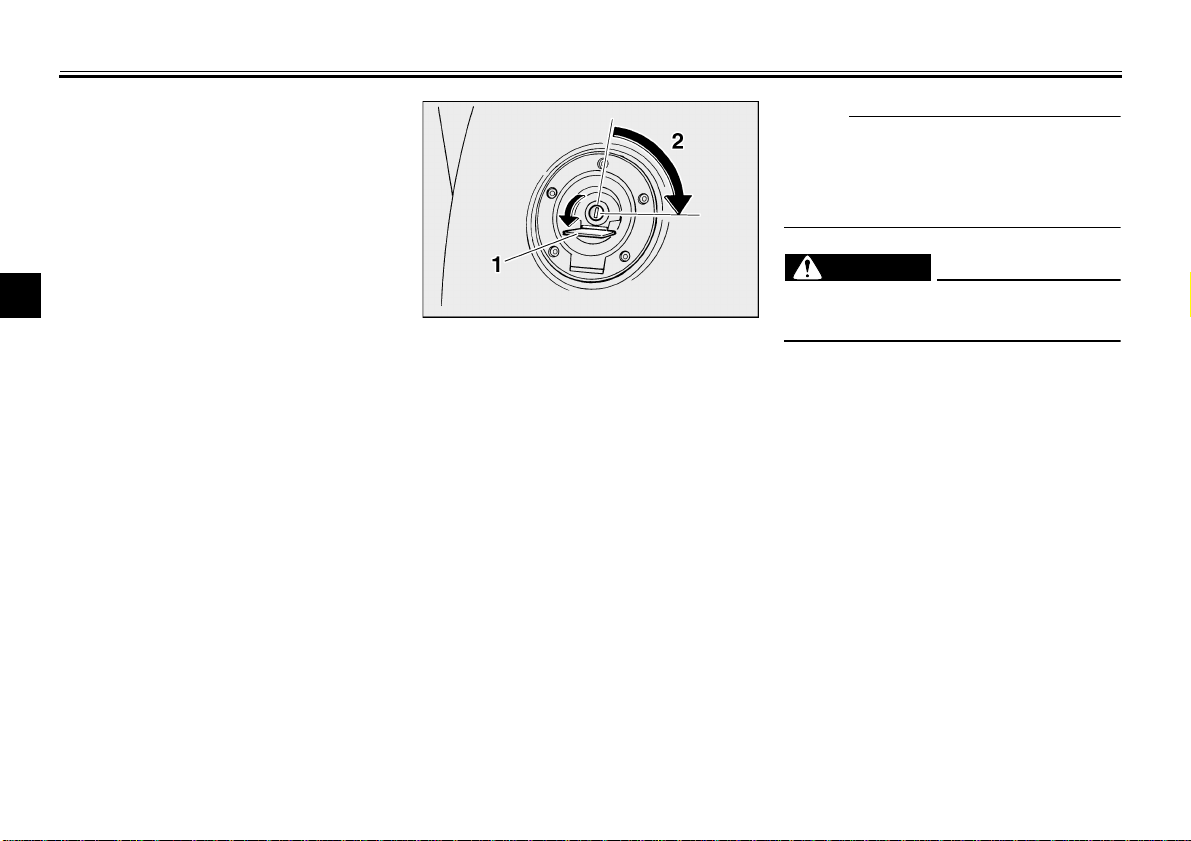
1. Fuel tank cap lock cover
2. Unlock.
EAU04068
Fuel tank cap
To open the fuel tank cap
Open the fuel tank cap lock cover, insert the key into the lock, and then turn
it 1/4 turn clockwise. The lock will be released and the fuel tank cap can be
opened.
To close the fuel tank cap
1. Push the fuel tank cap into position with the key inserted in the
lock.
2. Remove the key, and then close
the lock cover.
_
The fuel tank cap cannot be closed unless the key is in the lock. In addition,
the key cannot be removed if the cap is
not properly closed and locked.
_
_
EWA00025
Make sure that the fuel tank cap is
properly closed before riding.
_
3-9
1. Fuel tank filler tube
2. Fuel level
EAU03753
Fuel
Make sure that there is sufficient fuel in
the tank. Fill the fuel tank to the bottom
of the filler tube as shown.
WARNING
_
Do not overfill the fuel tank, oth-
●
erwise it may overflow when the
fuel warms up and expands.
Avoid spilling fuel on the hot
●
engine.
_
EW000130
INSTRUMENT AND CONTROL FUNCTIONS
EAU00185
CAUTION:
_
Immediately wipe off spilled fuel
with a clean, dry, soft cloth, since
fuel may deteriorate painted surfaces or plastic parts.
_
Recommended fuel:
Regular unleaded gasoline with a
research octane number of 91 or
higher
Fuel tank capacity:
Total amount:
25 L
Reserve amount:
5 L
NOTE:
_
If knocking (or pinging) occurs, use
gasoline of a different brand or with a
higher octane grade.
_
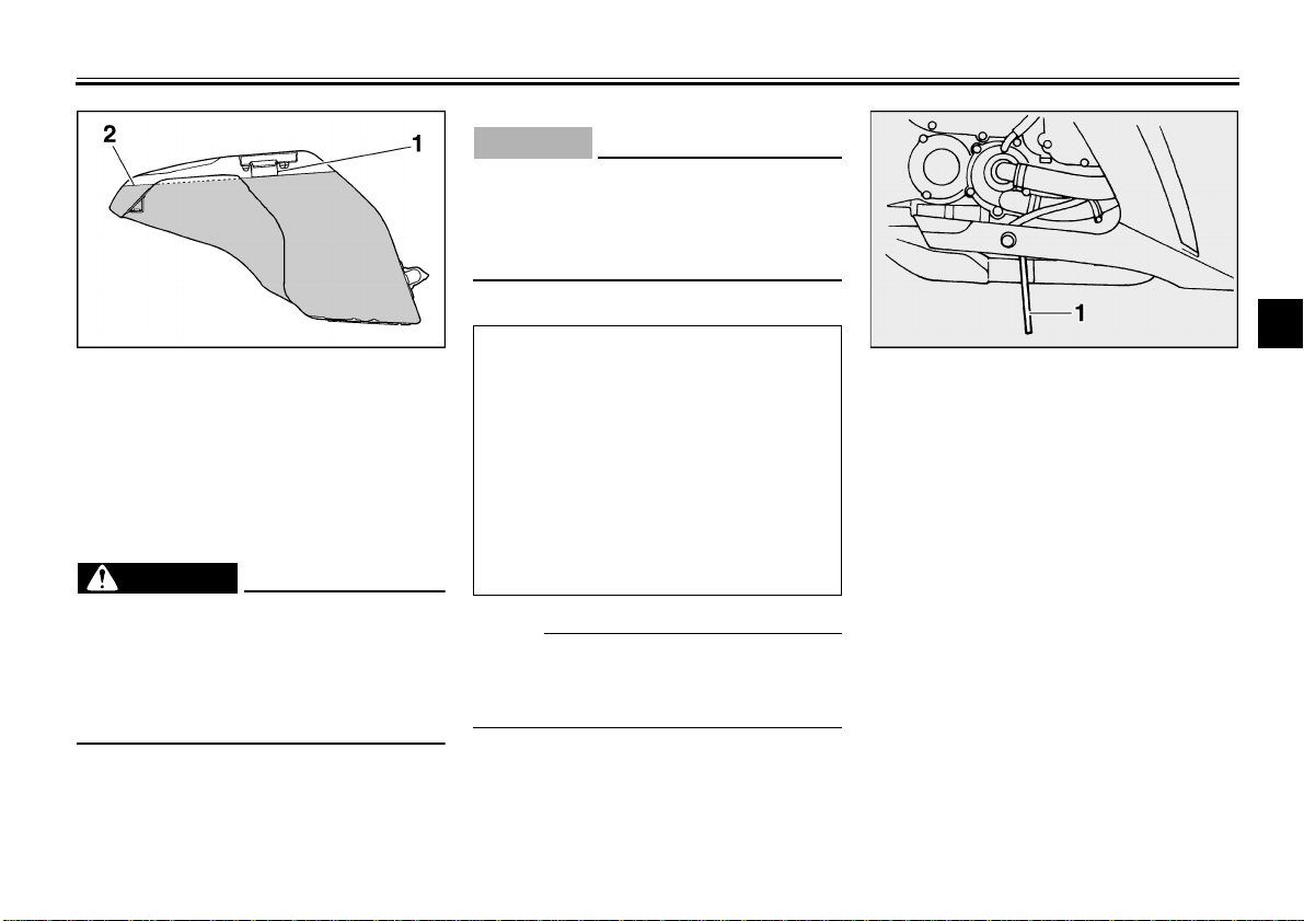
EAU00191
1. Fuel tank breather hose
Fuel tank breather hose
Before operating the motorcycle:
Check the fuel tank breather hose
●
connection.
Check the fuel tank breather hose
●
for cracks or damage, and replace
it if damaged.
Make sure that the end of the fuel
●
tank breather hose is not blocked,
and clean it if necessary.
3
EAU02955
3-10
INSTRUMENT AND CONTROL FUNCTIONS
NOTE:
3
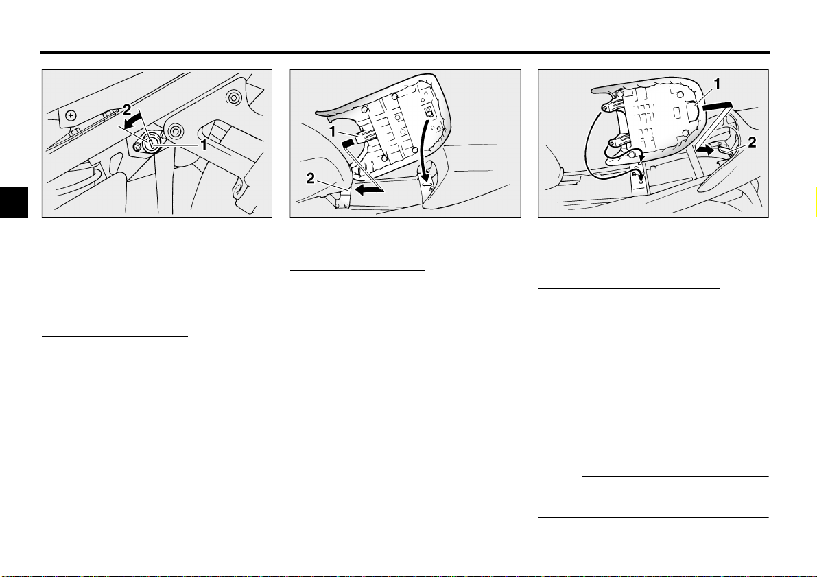
1. Rider seat lock
2. Unlock.
EAU03945
Seats
Rider seat
To remove the rider seat
1. Insert the key into the seat lock,
and then turn it as shown.
2. Pull the rider seat off.
1. Projection
2. Seat holder
To install the rider seat
1. Insert the projection on the front of
the rider seat into the seat holder
as shown, and then push the rear
of the seat down to lock it in place.
2. Remove the key.
3-11
1. Receptacle
2. Seat holder
Passenger seat
To remove the passenger seat
1. Remove the rider seat.
2. Pull the passenger seat up.
To install the passenger seat
1. Slide the receptacle on the rear of
the passenger seat over the seat
holder as shown, and then push
the front of the seat down.
2. Install the rider seat.
_
Make sure that the seats are properly
secured before riding.
_
INSTRUMENT AND CONTROL FUNCTIONS
EAU03949*
Adjusting the front fork
This front fork is equipped with spring
preload adjusting bolts, rebound damping force adjusting knobs and compression damping force adjusting screws.
WARNING
_
Always adjust both fork legs equal-
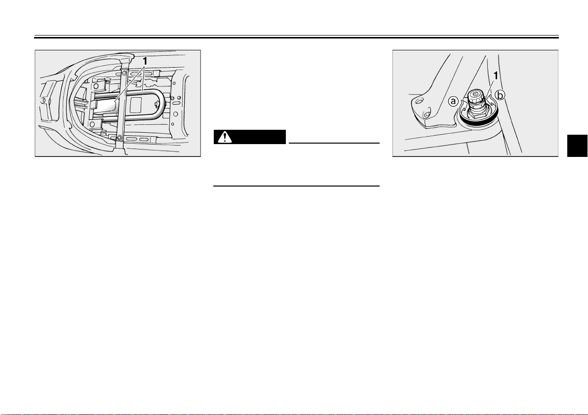
1. U-LOCK 1. Spring preload adjusting bolt
EAU01688
Storage compartment
ly, otherwise poor handling and loss
of stability may result.
_
This storage compartment is designed
to hold a genuine Yamaha U-LOCK.
(Other locks may not fit.) When placing
a U-LOCK in the storage compartment,
securely fasten it with the straps. When
the U-LOCK is not in the storage compartment, be sure to secure the straps
to prevent losing them.
When storing the owner’s manual or
other documents in the storage compartment, be sure to wrap them in a
plastic bag so that they will not get wet.
When washing the motorcycle, be
careful not to let any water enter the
storage compartment.
3-12
EW000035
Spring preload
To increase the spring preload and
thereby harden the suspension, turn
the adjusting bolt on each fork leg in direction a. To decrease the spring
preload and thereby soften the suspension, turn the adjusting bolt on each
fork leg in direction b.
3
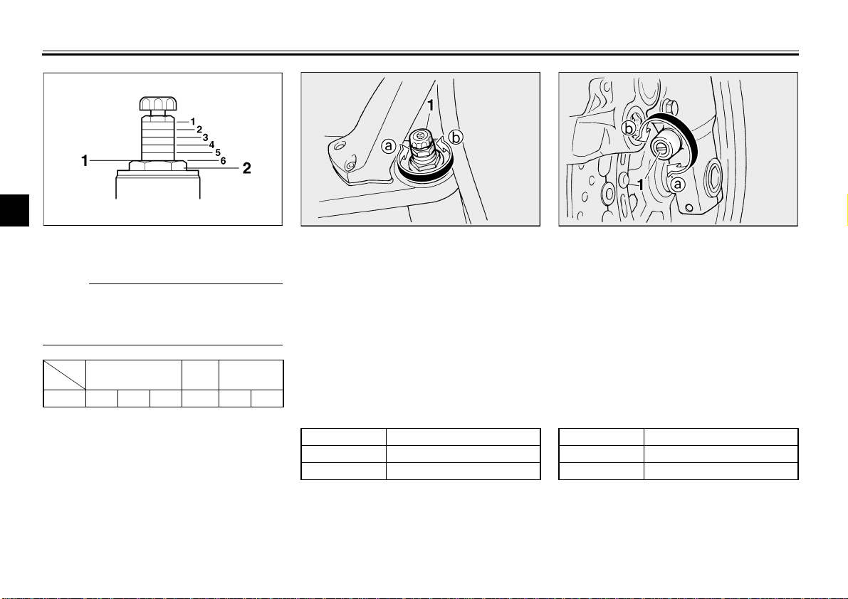
INSTRUMENT AND CONTROL FUNCTIONS
3
1. Current setting
2. Front fork cap bolt
NOTE:
_
Align the appropriate groove on the adjusting mechanism with the top of the
front fork cap bolt.
_
CI-01E
Hard
Setting123456
Stan-
dard
Soft
1. Rebound damping force adjusting knob
Rebound damping force
To increase the rebound damping
force and thereby harden the rebound
damping, turn the adjusting knob on
each fork leg in direction a. To decrease the rebound damping force and
thereby soften the rebound damping,
turn the adjusting knob on each fork leg
in direction b.
CI-09E
Minimum (soft) 17 clicks in direction b*
Standard 12 clicks in direction b*
Maximum (hard) 1 click in direction b*
* With the adjusting knob fully turned in direction
3-13
a
1. Compression damping force adjusting screw
Compression damping force
To increase the compression damping
force and thereby harden the compression damping, turn the adjusting screw
on each fork leg in direction a. To decrease the compression damping force
and thereby soften the compression
damping, turn the adjusting screw on
each fork leg in direction b.
CI-02E
Minimum (soft) 21 clicks in direction b*
Standard 12 clicks in direction b*
Maximum (hard) 1 click in direction b*
* With the adjusting screw fully turned in direction
a
INSTRUMENT AND CONTROL FUNCTIONS
EC000015
CAUTION:
_
Never attempt to turn an adjusting
mechanism beyond the maximum
or minimum settings.
_
NOTE:
_
Although the total number of clicks of a
damping force adjusting mechanism
may not exactly match the above specifications due to small differences in
production, the actual number of clicks
always represents the entire adjusting
range. To obtain a precise adjustment,
it would be advisable to check the number of clicks of each damping force adjusting mechanism and to modify the
specifications as necessary.
_
EAU03950
Adjusting the shock absorber
assembly
This shock absorber assembly is
equipped with a spring preload adjusting lever and a rebound damping force
adjusting knob.
CAUTION:
_
Never attempt to turn an adjusting
mechanism beyond the maximum
or minimum settings.
_
EC000015
3
1. Spring preload adjusting lever
a. “HARD”
b. “SOFT”
Spring preload
For riding solo, move the spring preload adjusting lever to “SOFT”. For
riding with a passenger, move the
spring preload adjusting lever to
“HARD”.
3-14
INSTRUMENT AND CONTROL FUNCTIONS
WARNING
_
This shock absorber contains highly pressurized nitrogen gas. For
proper handling, read and understand the following in formation before handling the shock absorber.
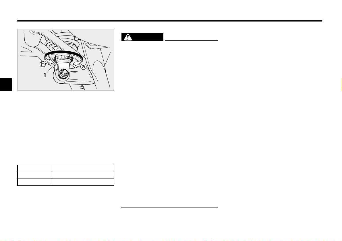
3
1. Rebound damping force adjusting knob
Rebound damping force
To increase the rebound damping
force and thereby harden the rebound
damping, turn the adjusting knob in direction a. To decrease the rebound
damping force and thereby soften the
rebound damping, turn the adjusting
knob in direction b.
CI-09E
Minimum (soft) 20 clicks in direction b*
Standard 10 clicks in direction b*
Maximum (hard) 3 clicks in direction b*
* With the adjusting knob fully turned in direction
The manufacturer cannot be held responsible for property damage or
personal injury that may result from
improper handling.
Do not tamper with or attempt to
●
open the gas cylinder.
Do not subject the shock ab-
●
sorber to an open flame or other
high heat sources, otherwise it
may explode due to excessive
gas pressure.
Do not deform or damage the
●
gas cylinder in any way, as this
will result in poor damping per-
a
formance.
Always have a Yamaha dealer
●
service the shock absorber.
_
EAU00315
3-15
 Loading...