


90894-62983-01Worldwide Edition
RIGGING GUIDE
2014


PREFACE
WARNING
NOTICE
The information in this guide is based on 2014 model specification information available at the time
when the guide has been issued.
Throughout this guide, Worldwide model names are given first followed by US and Canada model
names in parentheses for descriptive purpose.
For Australia and New Zealand, US and Canada model names are used for 4-stroke 150HP and
larger models.
In this guide, particularly important information is distinguished in the following ways.
A WARNING indicates a hazardous situation which, if not avoided, could result in death or
serious injury.
A NOTICE indicates special precautions that must be taken to avoid damage to the products
or other property.
Specifications and descriptions are subject to change without notice.
The PDF file is available from the service portal site maintained by Yamaha Motor Co., Ltd.
The following contracted terms are expediently used in this guide.
ASSY: assembly
DEC: Digital Electronic Remote Control
ECM: Electronic Control Module
EXT: extension
GND: ground, (–)
IG: ignition
LED: light emitting diode
MGT: management
NA: not applicable, not available
OP: optional
P/N: part number
PTT: power trim & tilt
PWR: power
RC: remote control
STD: standard
STR: steering
SW: switch
TBD: to be determined
© Yamaha Motor Co., Ltd.
All rights reserved.
Mar. 2014
Produced by
Technical Publication Division
After Sales Section
CS Center


CONTENTS
INSTALLATION............................................................................................1-1
TOP COVER PICTOGRAPH DESCRIPTION...............................................................1-2
ENGINE OIL REMINDER TAG (4-STROKE ENGINES)...............................................1-2
UNCRATING PROCEDURE
(FOR TYPICAL STEEL FRAME) .............................................................................. 1-3
MOUNTING THE OUTBOARD MOTOR....................................................................... 1-5
MOUNTING THE REMOTE OIL TANK.......................................................................1-11
OUTBOARD MOTOR DIMENSIONS..........................................................................1-12
PROPELLERS..............................................................................................2-1
PROPELLER SPECIFICATIONS.................................................................................. 2-2
PROPELLER SELECTION ...........................................................................................2-6
2014 PROPELLER APPLICATIONS ............................................................................2-6
WOT OPERATION RANGE TABLE ...........................................................................2-23
REMOTE CONTROLS .................................................................................3-1
REMOTE CONTROL TYPES AND APPLICATIONS....................................................3-2
REMOTE SWITCH TYPES AND APPLICATIONS .....................................................3-18
REMOTE CONTROL CABLES ...................................................................................3-33
REMOTE CONTROL ATTACHMENT KIT ..................................................................3-35
STEERING HOOK ......................................................................................................3-39
STEERING GUIDE ATTACHMENT KIT .....................................................................3-42
TIE-BAR KIT ...............................................................................................................3-44
CONVENTIONAL WIRE HARNESS ...........................................................................3-45
DIGITAL ELECTRONIC REMOTE CONTROL WIRE HARNESS ..............................3-46
TILLER HANDLES .......................................................................................4-1
6X4 MULTI-FUNCTION TILLER HANDLE ...................................................................4-2
STEERING FRICTION CONTENTS ...........................................................................4-24
To be continued.

CONTENTS
CONVENTIONAL GAUGE (6Y5 & 6Y7) ......................................................5-1
MOUNTING THE METERS ..........................................................................................5-4
ANALOG TACHOMETER .............................................................................................5-5
DIGITAL TACHOMETER ..............................................................................................5-7
SPEEDOMETER...........................................................................................................5-9
FUEL MANAGEMENT GAUGE ..................................................................................5-12
ANALOG TRIM METER..............................................................................................5-18
COOLANT PRESSURE METER ................................................................................5-19
COOLANT TEMP. METER .........................................................................................5-20
HOUR METER ............................................................................................................5-27
VOLTAGE METER......................................................................................................5-29
FUEL METER .............................................................................................................5-30
CHARGE WARNING UNIT .........................................................................................5-31
WIRE HARNESSES....................................................................................................5-32
WIRING DIAGRAMS...................................................................................................5-36
RIGGING GROMMET DESCRIPTION .......................................................................5-47
DIGITAL NETWORK GAUGE (6Y8) ............................................................6-1
DIGITAL NETWORK GAUGE COMPATIBLE MODELS ..............................................6-2
DIGITAL NETWORK GAUGE APPLICATION ..............................................................6-2
DIGITAL NETWORK GAUGE DIMENSIONS ...............................................................6-3
OPTIONAL EQUIPMENT..............................................................................................6-5
WIRE HARNESS ..........................................................................................................6-8
NETWORK HUB ...........................................................................................................6-9
OPTIONAL EQUIPMENT............................................................................................6-10
IMMOBILIZER UNIT ...................................................................................................6-11
NETWORK WIRING DIAGRAMS ...............................................................................6-12
INITIAL GAUGE SETUP .............................................................................................6-16
TROUBLESHOOTING ................................................................................................6-17
BASIC REQUIREMENTS ...........................................................................................6-18
NMEA0183 COMPATIBLE EQUIPMENT CONNECTION ..........................................6-18
DIGITAL NETWORK GAUGE (6Y8) FUNCTION TABLE ...........................................6-19
DIGITAL NETWORK PREMIUM GAUGE (6Y9) ..........................................7-1
DIGITAL NETWORK PREMIUM GAUGE COMPATIBLE MODELS............................. 7-3
DIGITAL NETWORK PREMIUM GAUGE APPLICATION ............................................7-3
DIGITAL NETWORK PREMIUM GAUGE DIMENSIONS .............................................7-4
OPTIONAL EQUIPMENT..............................................................................................7-5
NETWORK HUB ...........................................................................................................7-8
WIRE HARNESS ..........................................................................................................7-9
NETWORK WIRING DIAGRAMS ...............................................................................7-14
To be continued.

CONTENTS
BATTERY .....................................................................................................8-1
RECOMMENDED BATTERY........................................................................................8-2
BATTERY CABLE LENGTH .........................................................................................8-4
BATTERY WIRING .......................................................................................................8-6
APPENDIX....................................................................................................9-1
MODEL NAME DESIGNATION ....................................................................................9-3
FUEL SYSTEM VACUUM PRESSURE STANDARD ...................................................9-5
PORTABLE FUEL TANKS (TYPICAL) .........................................................................9-7
FUEL PIPES (TYPICAL) ...............................................................................................9-8
PRIMARY PUMP (TYPICAL) ........................................................................................9-8
PRE-DELIVERY INSPECTION (PDI) ...........................................................................9-9
CONVENTIONAL RIGGING KIT CONTENTS............................................................9-10
DIGITAL NETWORK GAUGE RIGGING KIT CONTENTS .........................................9-13
IMMOBILIZER RIGGING KIT CONTENTS.................................................................9-22
DIGITAL NETWORK PREMIUM GAUGE RIGGING KIT CONTENTS .......................9-24
OTHER RIGGING KIT CONTENTS............................................................................9-27
2014 YEAR MODELS MANUFACTURE STARTING SERIAL NUMBERS................. 9-30


INSTALLATION
TOP COVER PICTOGRAPH DESCRIPTION........................................... 1-2
ENGINE OIL REMINDER TAG (4-STROKE ENGINES) .......................... 1-2
UNCRATING PROCEDURE
(FOR TYPICAL STEEL FRAME) ......................................................... 1-3
MOUNTING THE OUTBOARD MOTOR .................................................. 1-5
WATER LEVEL GUIDELINE (4-STROKE ENGINES).......................... 1-9
ADJUSTING TWIN ENGINES ............................................................ 1-10
MAX. BOAT SPEED ESTIMATION .................................................... 1-10
MOUNTING THE REMOTE OIL TANK ..................................................1-11
REMOTE OIL TANK DIMENSIONS ................................................... 1-11
NOTICE FOR MOUNTING THE REMOTE OIL TANK ....................... 1-11
OUTBOARD MOTOR DIMENSIONS ..................................................... 1-12
OVERALL DIMENSION ITEMS..........................................................1-12
OVERALL DIMENSIONS (4-STROKE) .............................................. 1-14
OVERALL DIMENSIONS (2-STROKE) .............................................. 1-23
CLAMP BRACKET DIMENSION ITEMS ............................................ 1-29
CLAMP BRACKET DIMENSIONS...................................................... 1-30
1-1
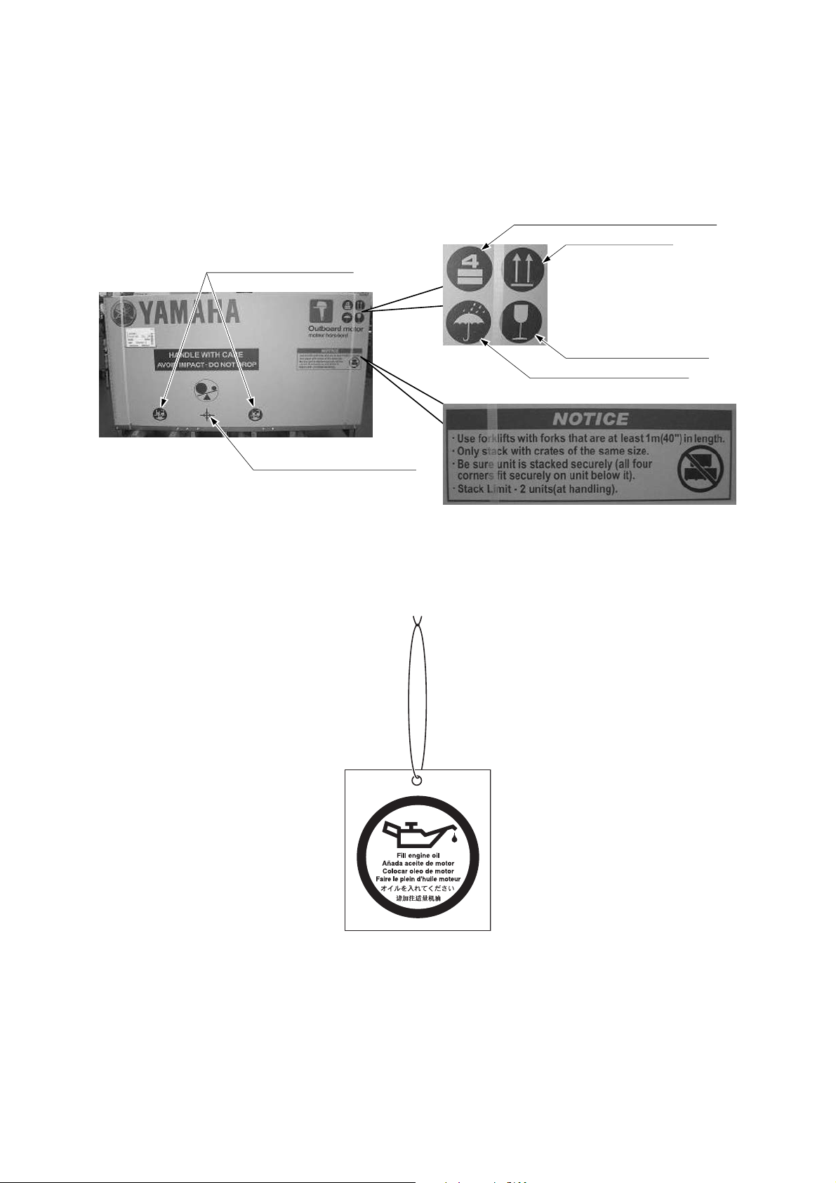
TOP COVER PICTOGRAPH DESCRIPTION
Product barycentric position
Lifting fork insert position
Stack limit: Max. 4 units for storage
Upward indication
Care handling indication
Water avoidance indication
The following pictographs are important sign to handle the crate.
Read the NOTICE and understand what pictographs mean to avoid a damage to the product when
handling, transporting and/or keeping the crate.
* Photo shows F350.
ENGINE OIL REMINDER TAG (4-STROKE ENGINES)
This tag is hung around the bottom cowling or the bracket to indicate that there is no engine oil in
the oil pan when the outboard motor is uncrated.
1-2
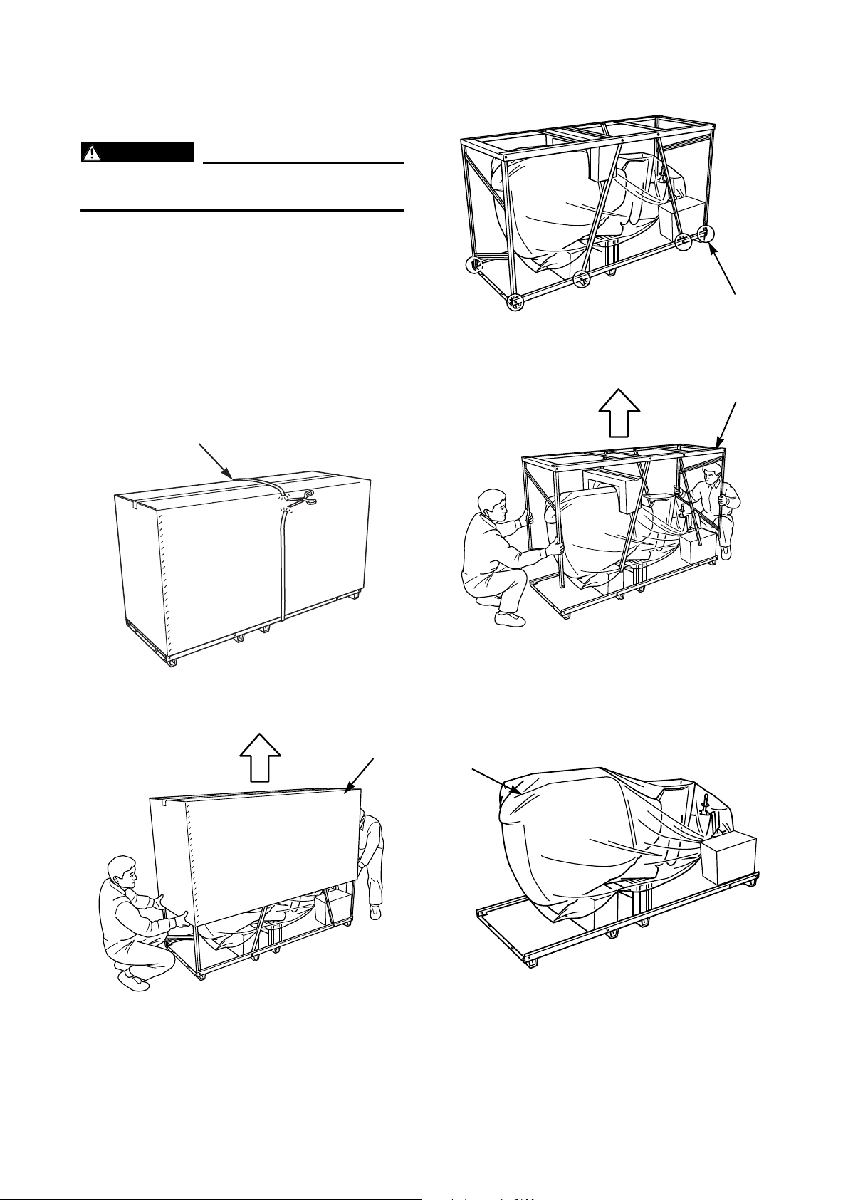
UNCRATING PROCEDURE
WARNING
(1)
(2)
(3)
(4)
(5)
(FOR TYPICAL STEEL FRAME)
Wear gloves to avoid injury by sharp steel
edges while uncrating.
This is an example of the steel crate for V6
models.
For other steel crate models, refer to this procedure for uncrating the steel frame.
1. Inspect the crate for shipping damage. If
any damage has been found, consult your
Yamaha dealer.
2. Cut the strap (1).
4. Remove the bottom bolts (3).
5. Lift the top frame (4) straight up.
3. Lift the top cover (2) straight up to remove.
6. Remove the wrapping (5), and inspect the
outboard motor for concealed damage. If
any damage is found, consult your Yamaha
dealer.
To be continued.
1-3
UNCRATING PROCEDURE
(6)
(7)
(8)
(7)
(8)
(A)(A)
(D)(D)
(B)(B)
(C)(C)
Eye bolt (C)Eye bolt (C)
Attachment (A)Attachment (A)
Eye bolt (C)
M10 bolt (B) M10 bolt (B)
90890-06821 (3 pcs)90890-06821 (3 pcs)
M10 bolt (B)
90890-06821 (3 pcs)
Attachment (A)
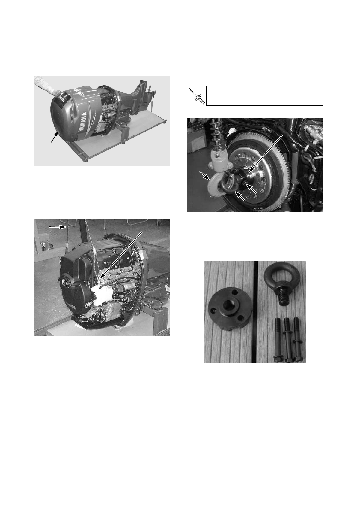
(FOR TYPICAL STEEL FRAME)
7. Remove the top cowling (6).
8. If the lifting points are covered by the flywheel cover, remove it.
9. Attach a lifting harness (7) securely to the
lifting points (8), and tighten the harness.
For 4-stroke V8, V6 (4.2L) and L4 (2.8L,
1.8L) engines, install the lifting attachment
(A) to the flywheel using the exclusive 3
bolts (B), insert the eye bolt (C) to the
attachment, attach a lifting harness (D) to
the eye bolt, and tension the harness.
M10 bolt (B) torque:
36 Nm, 3.6 kgf•m, 27 ft•lb
* Special service tool for 4-stroke V8, V6 (4.2L)
and L4 (2.8L) engines: Lifting eye kit (P/N:
90890-06820)
Lifting eye kit contents:
To be continued.
1-4
UNCRATING PROCEDURE
WARNING
(9)
(10)
*C/L: Centerline of the transom.
C/L
(a)
(b)
(c)
(d)
To be continued.
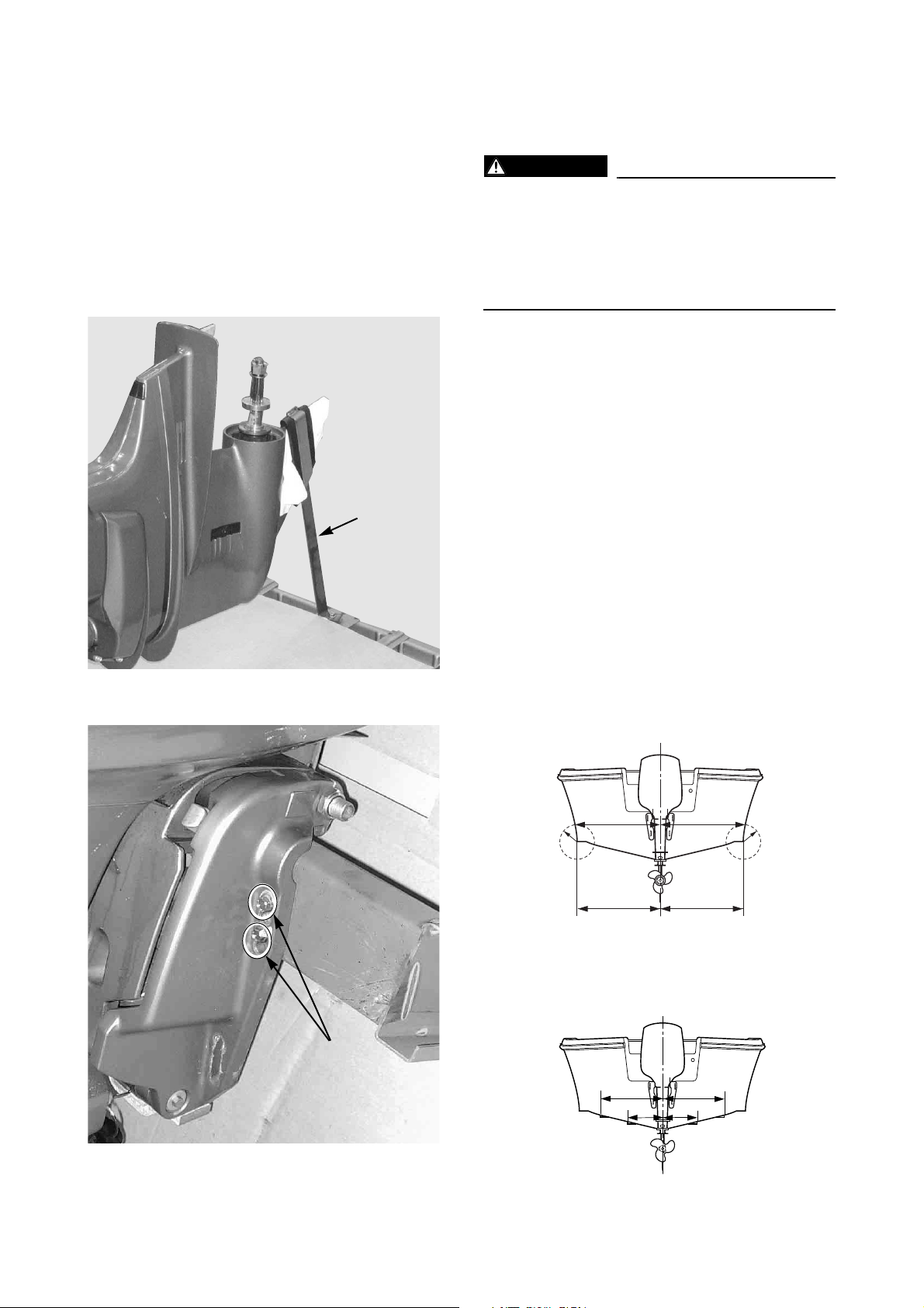
MOUNTING THE OUTBOARD
(FOR TYPICAL STEEL FRAME)
10. Carefully lift up the motor with the bottom
crate so that the lifting-harness does not
contact the engine components.
Have a helper hold the frame to avoid injury
while lifting.
11. Remove the skeg holder (9) if it is attached.
MOTOR
Overpowering a boat may cause severe
instability. Never install an outboard motor
that exceeds the maximum boat horsepower rating capacity. If a boat does not
have the capacity plate, ask to the boat
manufacturer.
Proper mount of outboard motor will obtain
better engine performance, product reliability,
fuel economy, customer satisfaction, etc.
This chapter describes the brief summary of
outboard motor mount.
For the first requirement, make sure the outboard motor has clearance for full movement,
from port to starboard, as well as during tilt
operation.
For the motor dimensions, see the later pages.
1. Set an outboard motor on the vertical center
line of boat transom.
Measurement points are shown in the illustration.
12. Remove the bracket bolts (10).
No strakes hull
Make a same radius (R) at both sides of hull,
and have another measurement points.
C/L
RR
(a)
(c)
(b)
(d)
Strakes hull
Make measurements between port and starboard strakes.
1-5
MOUNTING THE OUTBOARD
(T1)
C/L
(e)
(f)
(T1) (T1)
C/L
(T1) (T1)
C/L
(T1)
MOTOR
Recheck the measurements, and verify the
boat transom vertical centerline is straight.
Measurements (a) and (b) should be the
same, and measurement (c) and (d) should be
the same.
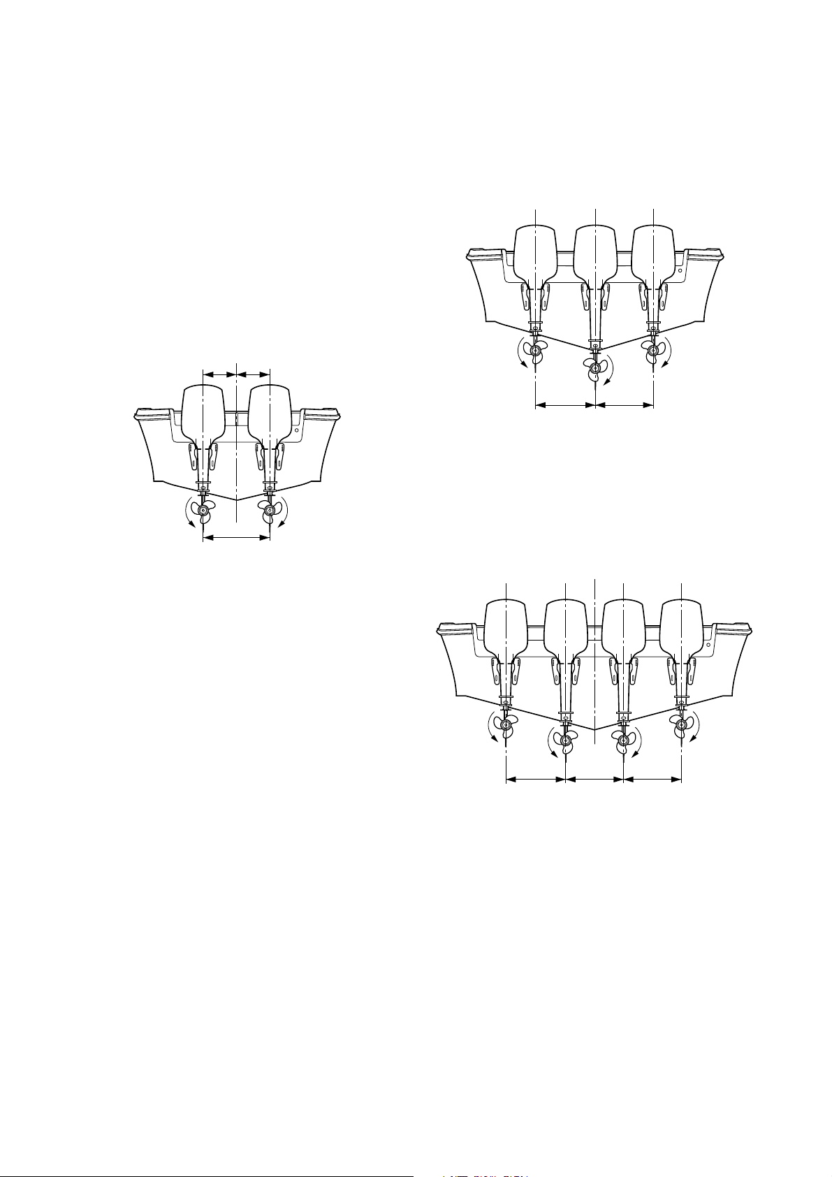
For twin engine application, set the engines
so that the distance between the boat transom
center line and the motor center line should be
equal for the both engines.
For triple engine application, set the engines
as shown below.
If a boat has V-hull, the center motor should
use longer transom motor than outside
engines.
For quad engine application, set the engines
as shown below.
If a boat has V-hull, inner twin engine should
use longer transom motor than outside
engines.
Measurements (e) and (f) should be the same.
Maintain a minimum distance (T1) that is the
measurement between both vertical centerlines of outboard motor.
Minimum distance (T1) is recommended on
each model, and its data is put on the dimension item.
To be continued.
1-6
MOUNTING THE OUTBOARD
0~25 mm (1 in.)
(a)
C/L
0~25 mm
(1 in.)
(a)
0~25 mm
(1 in.)
Twin engine application
Quad engine application
0~25 mm
(1 in.)
(a): Anti-cavitation plate
C/L
0~25 mm
(1 in.)
0~25 mm
(1 in.)
0~25 mm
(1 in.)
(a)
90
13 mm
(0.5 in.)
C/L
(H)
13 mm (0.5 in.)
(H)
(H): Motor transom height
Height position of
anti-cavitation plate
MOTOR
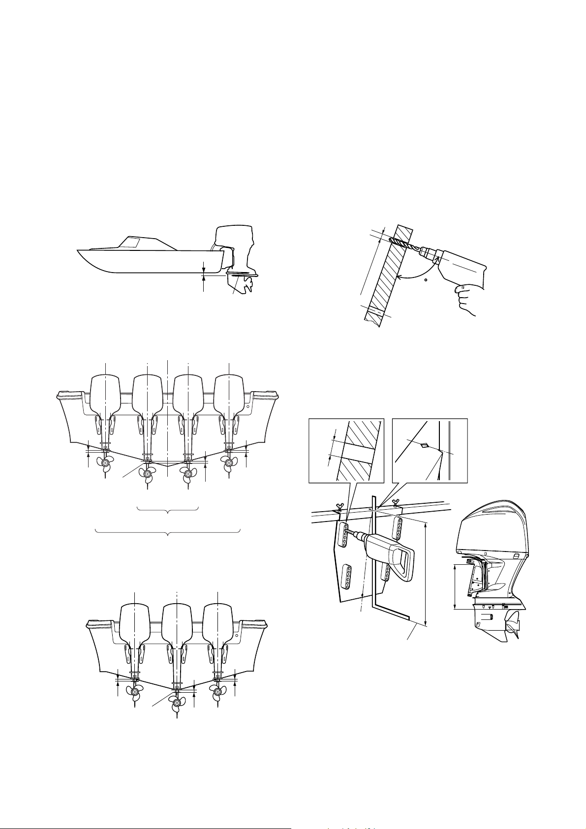
2. Adjust the height of outboard motor so that
the anti-cavitation plate is positioned to the
boat transom bottom, or lowered within 25
mm (1 in.).
For planing boats, the anti-cavitation plate
should be positioned to the boat transom
bottom or slightly higher.
Single engine application
Twin engine application/Quad engine application
* Due to combination of a boat type and an engine
type, the mount height of outboard motor varies.
Therefore, the complete information is impossible
to describe here.
For further information, see the instructions
issued by boat manufacturer, or ask to the manufacturer.
3. When the outboard motor mount position
has been determined, mark the 4 symmetrical mount hole positions onto the boat transom. Make the mount holes of 13 mm (0.5
in.) vertically on the marking points.
* To make the mounting holes easier, use the drill-
ing plate (P/N: 90890-06783 or YB-34465 for US).
Triple engine application
Ex: Drilling plate (90890-06783)
To be continued.
1-7
MOUNTING THE OUTBOARD
NOTICE
(a)
For reference:
(a)
(b)
(b)
(d)
(d)
(b)
(b)
(c)
(c)
(a) Mounting bolt
(b) Small washer
(c) Large washer
(d) Nut
: Sealant
T
M8: 18 Nm, 1.8 kgf•m, 13 lb•ft
M10: 36 Nm, 3.6 kgf•m, 27 lb•ft
M12: 52 Nm, 5.2 kgf•m, 38 lb•ft
MOTOR
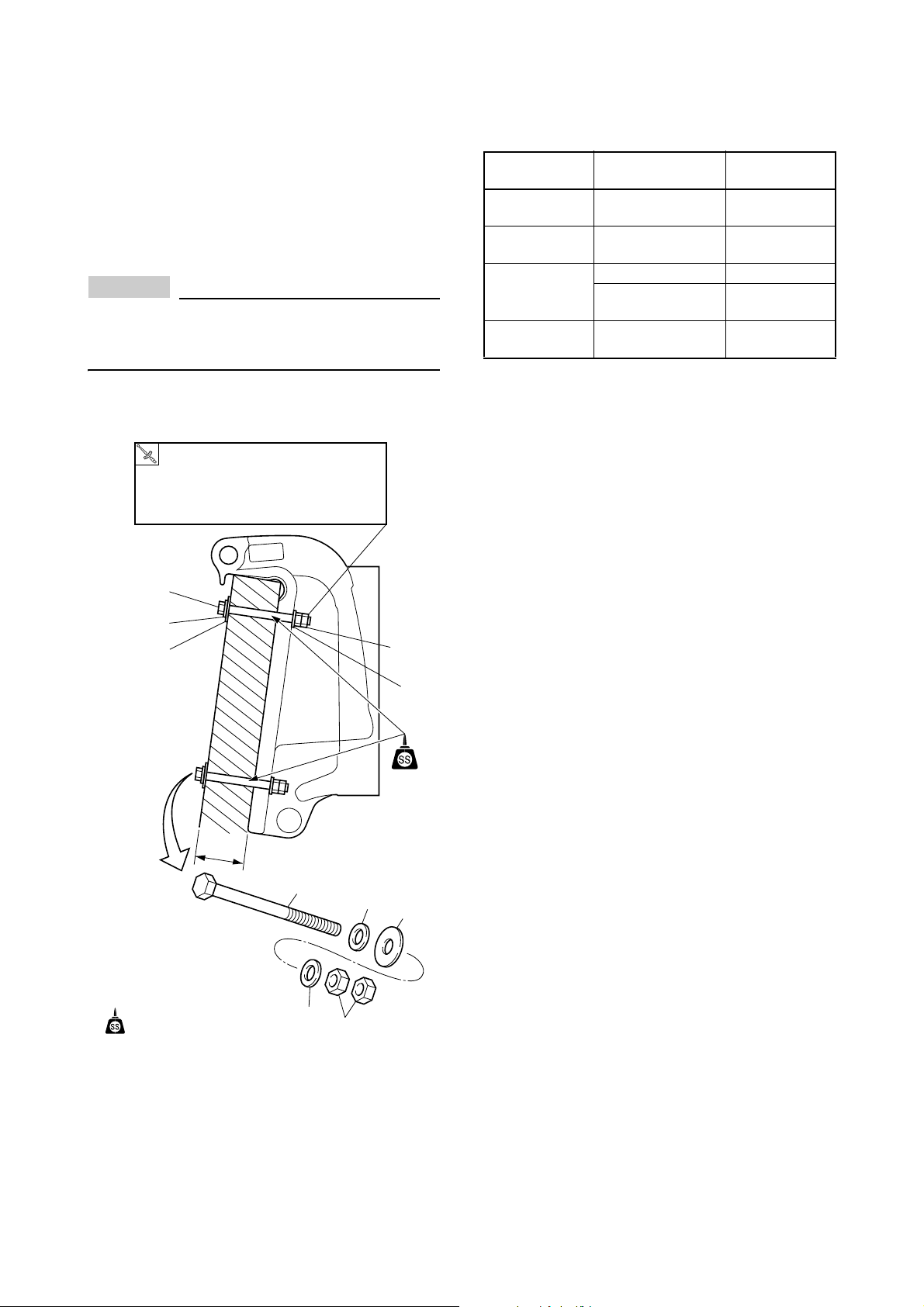
For above 115 (V4) and F75, select the tran-
som mount bolt depending on the boat transom thickness.
4. Apply sealant to the mount holes, and secure the motor with supplied mount hardware.
For tightening procedure, first tighten the inside nut, then the double nuts each other.
Make sure there is no clearance between
boat transom and motor clamp bracket.
Otherwise, the clamp bracket could break.
* The upper mount bolt is usually installed to
the 2nd hole from top.
Boat transom
thickness (T)
55 – 65 mm
(2.17 – 2.56 in.)
65 – 75 mm
(2.56 – 2.95 in.)
75 – 95 mm
(2.95 – 3.74 in.)
95 – 115 mm
(3.74 – 4.53 in.)
* High tension bolt is recommended for F350.
Mount bolt size Bolt P/N
M12 ×115 mm 90101-12M03
M12 ×130 mm 90101-12M05
M12 ×150 mm 90101-12M77
M12 ×150 mm
[High tension bolt]
M12 ×170 mm
[High tension bolt]
90101-12031
90101-12036
* Tighten the mounting bolts/nuts to suitable torque
depending on the boat transom structure, material, design, etc.
1-8
MOUNTING THE OUTBOARD MOTOR
Water surface
(H)
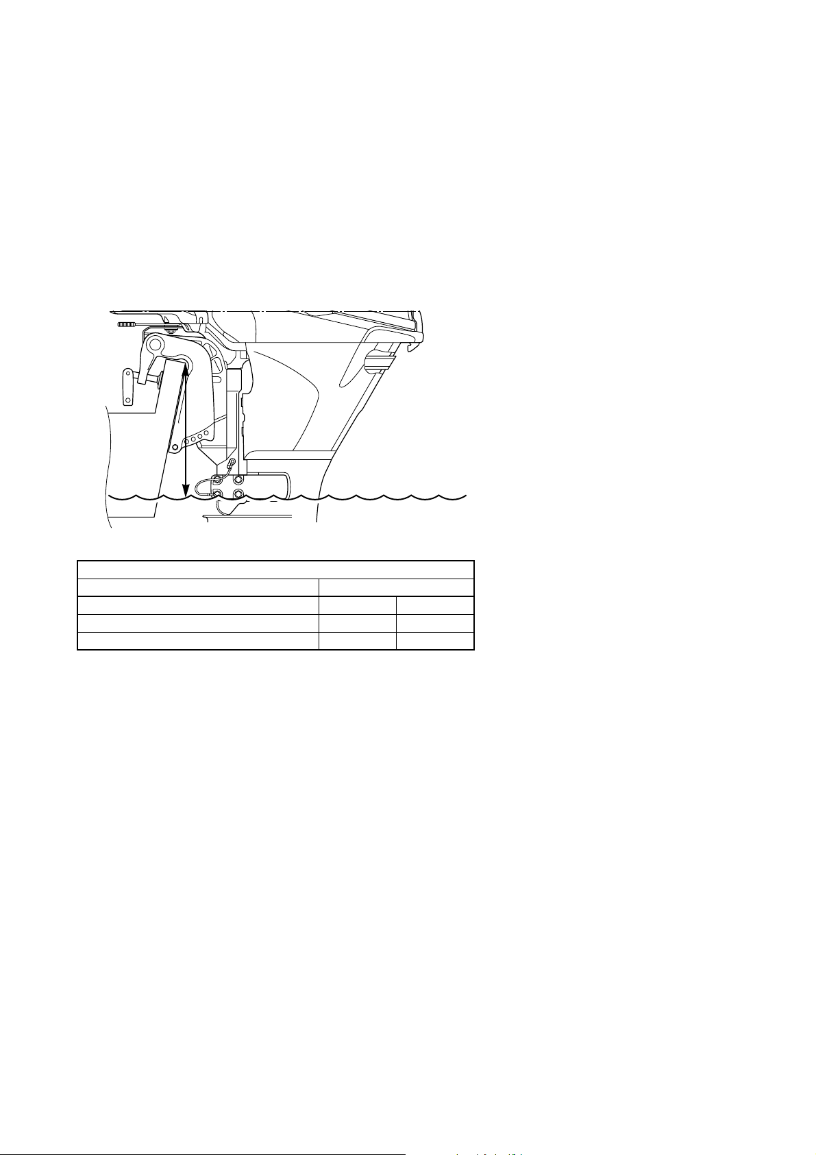
WATER LEVEL GUIDELINE (4-STROKE ENGINES)
If you replaced 2-stroke engine to 4-stroke engine which has the same horse power, a boat tends to
become “stern heavy” because of heavier engine weight.
As a result, water line will rise and get close to the power head.
This causes poor engine performance, and water could easily enter into the cylinder(s) and damage
the engine.
Therefore, you should consider the water level guideline when installing a 4-stroke outboard motor.
When mooring a boat with a maximum boat load, maintain the minimum height (H) shown in the
illustration between the water surface and the clamp bracket seating point.
Minimum height between water surface and bracket seating point
Model Min. height (H)
Carbureted F2 – F60 150 mm 5.9 in
Fuel injected F40 (4-cyl) – F70 100 mm 3.9 in
F75 and above 100 mm 3.9 in
1-9
MOUNTING THE OUTBOARD
(b)
(a)
7.5 – 15 m (25 – 50 ft)
MOTOR
ADJUSTING TWIN ENGINES
Set the engines in the toe-out position, and
measure the distances between the two
engines at the center point of the rear (a) and
front (b) of the lower casing. The difference
between measurement (a) and measurement
(b) should not exceed 25 mm (1 in.).
MAX. BOAT SPEED ESTIMATION
Depending on the engine power, boat length
and boat weight, the maximum boat speed can
be generally estimated with the calculation formula as below.
V = 1.398 L (PS/)
V = Estimated maximum boat speed (km/h)
L = Boat length (m)
PS = Prop shaft output power
= Displacement volume (ton)
For example:
Boat length = 8 m (27 ft)
Engine power = 250 ps
Displacement volume = 3 ton (3000 kg)
0.623
*water line
*water line
* Adjustment: (b) – (a) = Within 25 mm (1 in)
For best result, your toe-out distance should
be set so that the twin engines wake meets
approximately 7.5 – 15 m (25 – 50 ft) past the
stern of the boat.
Max. boat speed [V] = 1.398 8 (250/3)
0.623
= 62.2 km/h (38.6 mph)
* This should be only used as a reference.
The maximum boat speed varies depending on
the hull design, rigging state, passengers weight,
engine weight, engine position, etc.
Confirm the actual boat speed by test run.
1-10
MOUNTING THE REMOTE OIL
320 (12.6)
180 (7.1)230 (9.1)
mm (in.)
180 (7.1)
508 (20)
235 (9.3)
mm (in.)
250 (9.8)
200 (7.9)
170 (6.7)
6.5 (0.26)
40 (1.6)
200 (7.9)
25 (1.0)
112
(4.4)
30
(1.2)
173
(6.8)
210 (8.3)
160 (6.3)
130 (5.1)
30
(1.2)
mm (in.)
TANK
The remote oil tank is required for 2-stroke V4
and V6 oil injection engines.
REMOTE OIL TANK DIMENSIONS
10.5 liter (2.8 US gallons) tank P/N: 6E5-21733-20
18 liter (4.8 US gallons) tank P/N: 6E5-21733-30
Oil tank holder
NOTICE FOR MOUNTING THE REMOTE OIL TANK
Follow the notifications below, for the remote
oil tank installation.
• Mount the oil tank in as dry as possible location to avoid water entering into the oil tank.
• Mount in a location that will allow service to
the filter located on the remote oil tank.
• Mount the remote oil tank lower than the
engine oil tank.
If the remote oil tank is mounted higher than
the top of the engine because of the boat
type, an optional check valve (P/N: 6R524408-00) shown below is required.
Install the check valve on the oil hose
between the engine and remote oil tank to
prevent siphoning of oil to the engine and
spillage.
• Route the oil hose between the engine and
the remote oil tank without pinching and
kinking.
1-11

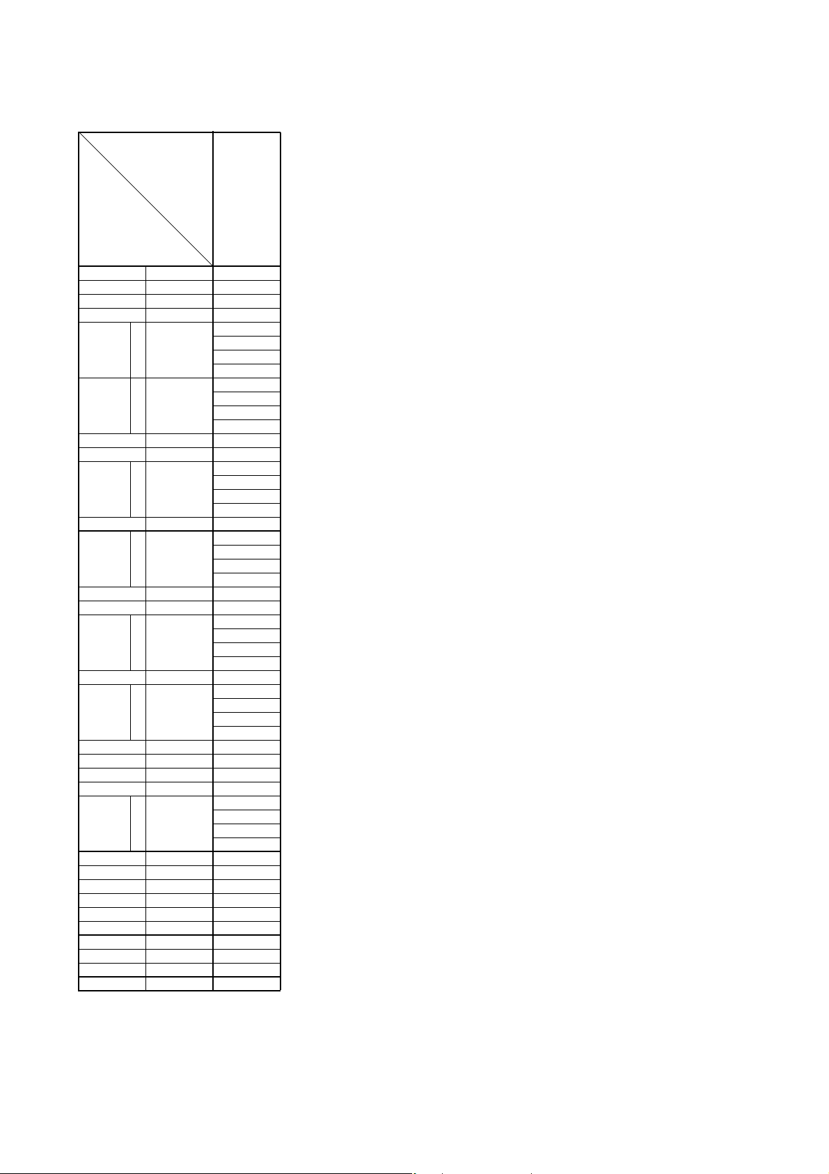
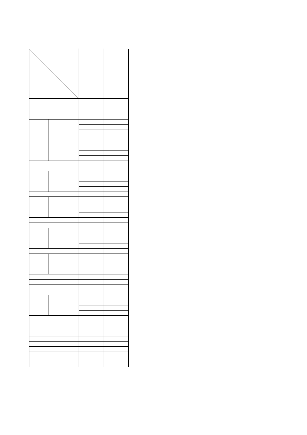
OUTBOARD MOTOR DIMENSIONS
OVERALL DIMENSION ITEMS
Symbol Definition and Description
L1 Horizontal distance from datum point to rearmost point of power unit
L2 Horizontal distance from datum point to forefront (depends on the model) of power unit
L3
L4 Horizontal distance from datum point to rearmost point of the lower case
L5
L6
L7
L8
L9 Horizontal forward protrusion of lower case from the datum line when PTT is fully trimmed down
L10 Horizontal distance from datum point to bracket shaft (bolt) center
H1 Vertical distance from datum point to lowest point of motor
H2 Vertical distance from datum point to highest point of power head
H3 Vertical distance from anti-cavitation plate undersurface to the center of propeller shaft
H4 Vertical distance from datum point to anti-cavitation plate undersurface
H5 Vertical distance from datum point to tiller handle tip when the handle is in vertical position
H6
H7 Vertical distance from datum line to protruded forefront when motor is tilted up (over-tilt position)
H8
H9 Vertical distance to the highest point of the motor when it is tilted up (over-tilt position)
H10 Vertical distance from datum point to bracket shaft (bolt) center
H11
W1 Leftward protrusion from center line of motor body when looking at the front face
W2 Distance from tiller handle tip to centerline of motor body when looking at the front face
W3 Distance from centerline to left or right edge of motor body, except for levers and handles
W4
W5 Distance from centerline to the farthest point on the body when steered to the maximum angle
W6
A1 Maximum steering angle each way (symmetrical), from centerline of motor body
A2 Tilt up angle (whole rotating range to over-tilt angle including negative trim angle)
A3 Maximum negative trim angle from the vertical line through the datum point
T1 Centerline-to-centerline minimum distance of the engines in case of twin installation
Distance from datum point to farthest point on tiller handle, when the handle is in horizontal position (in use)
Minimum distance from transom board or its extension to forefront of the lower case, with motor
fully trimmed down and steered to the full
Horizontal distance from datum point to rearmost point of protrusion when motor is tilted up (overtilt position)
Horizontal distance from datum point to protruded forefront when motor is tilted up (over-tilt position)
Horizontal distance from datum point to lowest point of protrusion when motor is tilted up (over-tilt
position)
Vertical distance from skeg tip at H1 to the lowest point of lower unit when motor is tilted up (overtilt position)
Vertical distance from datum line to lowest point of protrusion when motor is tilted up (over-tilt
position)
Difference in the height of lower unit lowest point comparing to the height in the standard position
and with PTT in the fully trimmed down position.
Distance from centerline to left or right end of motor body protrusion, except for levers and handles
Distance from centerline to the farthest point on the tiller handle when steered to the maximum
angle
1-12
OUTBOARD MOTOR DIMENSIONS
L
4
A
3
H
6
L
6
L
7
L
3
L
2
L
1
W
3
W
4
A
1
W
5
W
6
W
2
W
1
H
10
H
8
H
7
H
2
H
5
H
4
H
3
H
11
H
9
H
1
L
10
L
8
L
5
12
A
2
T
1
L
9
OVERALL DIMENSION ITEMS
1-13

OUTBOARD MOTOR DIMENSIONS
OVERALL DIMENSIONS (4-STROKE)
Global model
(US, CA model)
F2AMH
F2.5AMH
Symbol
L1 mm (in) 315 (12.4) 315 (12.4) 409 (16.1) 430 (16.9) 430 (16.9) 430 (16.9) 430 (16.9) 430 (16.9)
L2 mm (in) 93 (3.7) 93 (3.7) 130 (5.1) 122 (4.8) 122 (4.8) 122 (4.8) 122 (4.8) 122 (4.8)
L3 mm (in) 309 (12.2) 309 (12.2) 341 (13.4) 608 (23.9) 498 (19.6) 608 (23.9) — —
L4 mm (in) 215 (8.5) 215 (8.5) 259 (10.2) 355 (14.0) 355 (14.0) 367 (14.4) 367 (14.4) 367 (14.4)
S
L 57 (2.2) 57 (2.2) 93 (3.7) 99 (3.9) 99 (3.9) 99 (3.9) 99 (3.9) 99 (3.9)
L5
L6
L7 mm (in) 366 (14.4) 388 (15.3) 383 (15.1) 271 (10.7) 271 (10.7) 271 (10.7) 271 (10.7) 271 (10.7)
L8 mm (in) 167 (6.6) 167 (6.6) 134 (5.3) 139 (5.5) 139 (5.5) 139 (5.5) 139 (5.5) 225 (8.9)
L9
L10 mm (in) 75 (3.0) 57 (2.2) 63 (2.5) 67 (2.6) 67 (2.6) 67 (2.6) 67 (2.6) 67 (2.6)
H1
H2 mm (in) 376 (14.8) 397 (15.6) 395 (15.6) 318 (12.5) 318 (12.5) 318 (12.5) 318 (12.5) 318 (12.5)
H3 mm (in) 103 (4.1) 103 (4.1) 104 (4.1) 123 (4.8) 123 (4.8) 157 (6.2) 157 (6.2) 157 (6.2)
H4
H5 mm (in) 470 (18.5) 470 (18.5) 430 (16.9) 673 (26.5) 563 (22.2) 673 (26.5) — —
H6
H7 mm (in) 264 (10.4) 255 (10.0) 191 (7.5) 203 (8.0) 203 (8.0) 203 (8.0) 203 (8.0) 203 (8.0)
H8 mm (in) 15 (0.6) 15 (0.6) 0.6 (0.02) 5 (0.2) 5 (0.2) 5 (0.2) 5 (0.2) 5 (0.2)
H9 mm (in) 406 (16.0) 406 (16.0) 503 (19.8) 529 (20.8) 529 (20.8) 529 (20.8) 529 (20.8) 529 (20.8)
H10 mm (in) 32 (1.3) 32 (1.3) 39 (1.5) 32 (1.3) 32 (1.3) 32 (1.3) 32 (1.3) 32 (1.3)
H11
W1 mm (in) 140 (5.5) 140 (5.5) 181 (7.1) 159 (6.3) 169 (6.7) 172 (6.8) 177 (7.0) 177 (7.0)
W2 mm (in) 205 (8.1) 205 (8.1) 222 (8.7) 199 (7.8) 206 (8.1) 199 (7.8) — 135 (5.3)
W3 mm (in) 139 (5.5) 139 (5.5) — 159 (6.3) 159 (6.3) 159 (6.3) 159 (6.3) 159 (6.3)
W4 mm (in) 135 (5.3) 135 (5.3) 153 (6.0) 159 (6.3) 159 (6.3) 159 (6.3) 159 (6.3) 159 (6.3)
W5 mm (in) — — 325 (12.8) 286 (11.3) 286 (11.3) 286 (11.3) 286 (11.3) 271 (10.7)
W6 mm (in) — — 425 (16.7) 619 (24.4) 536 (21.1) 619 (24.4) — 271 (10.7)
A1 degree 360 360 90 45 45 45 45 40
A2 degree 80 80 69 66 66 66 66 66
A3degree————————
T1mm (in)————————
mm (in)
X —————99 (3.9)99 (3.9)99 (3.9)
U ————————
S
L 761 (30.0) 761 (30.0) 753 (29.6) 822 (32.4) 822 (32.4) 879 (34.6) 879 (34.6) 879 (34.6)
mm (in)
X —————941 (37.0)941 (37.0) 941 (37.0)
U ————————
S
L ————————
mm (in)
X ————————
U ————————
S
L 772 (30.4) 772 (30.4) 771 (30.4) 809 (31.9) 809 (31.9) 869 (34.2) 869 (34.2) 869 (34.2)
mm (in)
X —————937 (36.9)937 (36.9) 937 (36.9)
U ————————
S
L 559 (22.0) 559 (22.0) 562 (22.1) 563 (22.2) 563 (22.2) 557 (21.9) 557 (21.9) 557 (21.9)
mm (in)
X —————625 (24.6)625 (24.6) 625 (24.6)
U ————————
S
L 746 (29.4) 746 (29.4) 637 (25.1) 669 (26.3) 669 (26.3) 717 (28.2) 717 (28.2) 717 (28.2)
mm (in)
X —————757 (29.8)757 (29.8) 757 (29.8)
U ————————
S
L ————————
mm (in)
X ————————
U ————————
57 (2.2) 57 (2.2) 71 (2.8) 72 (2.8) 72 (2.8) — — —
636 (25.0) 636 (25.0) 635 (25.0) 706 (27.8) 706 (27.8) — — —
————————
645 (25.4) 645 (25.4) 644 (25.4) 682 (26.9) 682 (26.9) — — —
432 (17.0) 432 (17.0) 435 (17.1) 436 (17.2) 436 (17.2) — — —
642 (25.3) 642 (25.3) 555 (21.9) 594 (23.4) 594 (23.4) — — —
————————
(F2.5MHA)
w/ EPA cap
F4BMH
(F4MHA)
F5AMH
F6CMH
(F6MHA)
F8CMH
(F8MHA)
Long handle
F8CMH
F8CWH
Short handle
FT8DMH
Long handle
FT8DE FT8DEP
1-14

OUTBOARD MOTOR DIMENSIONS
OVERALL DIMENSIONS (4-STROKE)
F9.9HMH
Global model
(US, CA model)
Symbol
L1 mm (in) 436 (17.2) 436 (17.2) 436 (17.2) 435 (17.1) 436 (17.2) 435 (17.1) 489 (19.3) 488 (19.2)
L2 mm (in) 124 (4.9) 121 (4.8) 121 (4.8) 122 (4.8) 121 (4.8) 122 (4.8) 219 (8.6) 220 (8.7)
L3 mm (in) 547 (21.5) — 607 (23.9) 608 (23.9) — — 559 (22.0) 559 (22.0)
L4 mm (in) 356 (14.0) 356 (14.0) 367 (14.4) 367 (14.4) 367 (14.4) 367 (14.4) 387 (15.2) 386 (15.2)
S
L 67 (2.6) 67 (2.6) 67 (2.6) 35 (1.4) 67 (2.6) 35 (1.4) 82 (3.2) 82 (3.2)
L5
L6
L7 mm (in) 276 (10.9) 276 (10.9) 276 (10.9) 273 (10.7) 276 (10.9) 273 (10.7) 381 (15.0) 356 (14.0)
L8 mm (in) 141 (5.6) 138 (5.4) 138 (5.4) 139 (5.5) 138 (5.4) 139 (5.5) 237 (9.3) 176 (6.9)
L9
L10 mm (in) 66 (2.6) 66 (2.6) 66 (2.6) 67 (2.6) 66 (2.6) 67 (2.6) 66 (2.6) 67 (2.6)
H1
H2 mm (in) 331 (13.0) 331 (13.0) 331 (13.0) 326 (12.8) 331 (13.0) 326 (12.8) 377 (14.8) 372 (14.6)
H3 mm (in) 123 (4.8) 123 (4.8) 157 (6.2) 157 (6.2) 157 (6.2) 157 (6.2) 133 (5.2) 133 (5.2)
H4
H5 mm (in) 614 (24.2) — 678 (26.7) 673 (26.5) — — 570 (22.4) 566 (22.3)
H6
H7 mm (in) 216 (8.5) 216 (8.5) 216 (8.5) 213 (8.4) 216 (8.5) 273 (10.7) 399 (15.7) 414 (16.3)
H8 mm (in) 7 (0.3) 8 (0.3) 8 (0.3) 5 (0.2) 8 (0.3) 5 (0.2) 44 (1.7) 37 (1.5)
H9 mm (in) 527 (20.8) 527 (20.7) 609 (24.0) 604 (23.8) 527 (20.7) 522 (20.6) 580 (22.8) 575 (22.6)
H10 mm (in) 37 (1.5) 37 (1.5) 37 (1.5) 32 (1.3) 37 (1.5) 32 (1.3) 37 (1.5) 32 (1.3)
H11
W1 mm (in) 156 (6.1) 177 (7.0) 172 (6.8) 172 (6.8) 177 (7.0) 177 (7.0) 210 (8.3) 210 (8.3)
W2 mm (in) 188 (7.4) — 189 (7.4) 189 (7.4) — — 210 (8.3) 210 (8.3)
W3 mm (in) 156 (6.1) 156 (6.1) 156 (6.1) 156 (6.1) 156 (6.1) 156 (6.1) 176 (6.9) 176 (6.9)
W4 mm (in) 156 (6.1) 156 (6.1) 156 (6.1) 156 (6.1) 156 (6.1) 156 (6.1) — —
W5 mm (in) 284 (11.2) 284 (11.2) 284 (11.2) 265 (10.4) 284 (11.2) 265 (10.4) 341 (13.4) 320 (12.6)
W6 mm (in) 562 (22.1) — 603 (23.7) 567 (22.3) — — 598 (23.5) 568 (22.4)
A1degree4343433843384540
A2degree7171717471747167
3degree
A
T1mm (in)————————
mm (in)
X — — 67 (2.6) 35 (1.4) 67 (2.6) 35 (1.4) — —
U ————————
S
L 823 (32.4) 823 (32.4) 880 (34.6) 879 (34.6) 880 (34.6) 879 (34.6) 847 (33.3) 840 (33.1)
mm (in)
X — — 943 (37.1) 941 (37.0) 943 (37.1) 941 (37.0) — —
U ————————
S
L 27 (1.1) 27 (1.1) 27 (1.1) 62 (2.4) 27 (1.1) 62 (2.4) 18 (0.7) 18 (0.7)
mm (in)
X — — 27 (1.1) 62 (2.4) 27 (1.1) — — —
U ————————
S
L 804 (31.7) 804 (31.7) 864 (34.0) 869 (34.2) 864 (34.0) 869 (34.2) 828 (32.6) 833 (32.8)
mm (in)
X — — 932 (36.7) 937 (36.9) 932 (36.7) 937 (36.9) — —
U ————————
S
L 558 (22.0) 558 (22.0) 552 (21.7) 557 (21.9) 552 (21.7) 557 (21.9) 565 (22.2) 570 (22.4)
mm (in)
X — — 620 (24.4) 625 (24.6) 620 (24.4) 625 (24.6) — —
U ————————
S
L 682 (26.9) 682 (26.9) 730 (28.7) 717 (28.2) 730 (28.7) 717 (28.2) 694 (27.3) 643 (25.3)
mm (in)
X — — 771 (30.4) 757 (29.8) 771 (30.4) 757 (29.8) — —
U ————————
S
L 19 (0.7) 19 (0.7) 19 (0.7) 33 (1.3) 19 (0.7) 33 (1.3) 19 (0.7) 19 (0.7)
mm (in)
X — — 19 (0.7) 33 (1.3) 19 (0.7) 33 (1.3) — —
U ————————
F9.9JMH
(F9.9MHB)
F9.9JEH
(F9.9EHB)
F9.9JWH
49 (1.9) 49 (1.9) — — — — 64 (2.5) —
707 (27.8) 707 (27.8) — — — — 730 (28.7) —
18 (0.7) 18 (0.7) — — — — 9 (0.4) —
677 (26.7) 677 (26.7) — — — — 701 (27.6) —
431 (17.0) 431 (17.0) — — — — 438 (17.2) —
604 (23.8) 604 (23.8) — — — — 616 (24.3) —
19 (0.7) 19 (0.7) — — — — 19 (0.7) —
44484844
F9.9JE
(F9.9EB)
FT9.9LMH
(T9.9MHB)
FT9.9LWH
(T9.9EHB)
FT9.9LEHP
(T9.9PHB)
FT9.9LE
(T9.9EB)
FT9.9LEP
(T9.9PB)
F15CMH
(F15MHA)
F15CEH
(F15EHA)
F15CWH
F20BMH
(F20MHA)
F20BEH
(F20EHA)
F20BWH
F20CMH
F15CEHP
(F15PHA)
F20BEHP
(F20PHA)
1-15

OUTBOARD MOTOR DIMENSIONS
OVERALL DIMENSIONS (4-STROKE)
Global model
(US, CA model)
Symbol
L1 mm (in) 489 (19.3) 488 (19.2) 601 (23.7) 601 (23.7) 601 (23.7) 601 (23.7) 601 (23.7) 601 (23.7)
L2 mm (in) 176 (6.9) 176 (6.9) — — — 255 (10.0) 123 (4.8) 123 (4.8)
L3 mm (in) — — 580 (22.8) 580 (22.8) 580 (22.8) 769 (30.3) — —
L4 mm (in) 387 (15.2) 386 (15.2) 433 (17.0) 433 (17.0) 433 (17.0) 433 (17.0) 433 (17.0) 433 (17.0)
S
L 82 (3.2) 82 (3.2) 103 (4.1) 111 (4.4) 111 (4.4) 103 (4.1) 103 (4.1) 111 (4.4)
L5
L6
L7 mm (in) 321 (12.6) 309 (12.2) 378 (14.9) 353 (13.9) 353 (13.9) 378 (14.9) 378 (14.9) 353 (13.9)
L8 mm (in) 184 (7.2) 188 (7.4) 189 (7.4) 197 (7.8) 197 (7.8) 159 (6.3) 147 (5.8) 150 (5.9)
L9
L10 mm (in) 66 (2.6) 67 (2.6) 65 (2.6) 65 (2.6) 65 (2.6) 65 (2.6) 65 (2.6) 65 (2.6)
H1
H2 mm (in) 377 (14.8) 372 (14.6) 450 (17.7) 450 (17.7) 450 (17.7) 450 (17.7) 450 (17.7) 450 (17.7)
H3 mm (in) 133 (5.2) 133 (5.2) 144 (5.7) 144 (5.7) 144 (5.7) 144 (5.7) 144 (5.7) 144 (5.7)
H4
H5mm (in)—————766 (30.2)——
H6
H7 mm (in) 218 (8.6) 230 (9.1) 258 (10.2) 282 (11.1) 282 (11.1) 258 (10.2) 258 (10.2) 282 (11.1)
H8 mm (in) 32 (1.3) 28 (1.1) 41 (1.6) 26 (1.0) 26 (1.0) 47 (1.9) 12 (0.5) 22 (0.9)
H9 mm (in) 580 (22.8) 575 (22.6) 705 (27.8) 706 (27.8) 706 (27.8) 705 (27.8) 705 (27.8) 706 (27.8)
H10 mm (in) 37 (1.5) 32 (1.3) 43 (1.7) 43 (1.7) 43 (1.7) 43 (1.7) 43 (1.7) 43 (1.7)
H11
W1 mm (in) 210 (8.3) 210 (8.3) 199 (7.8) 199 (7.8) 199 (7.8) 199 (7.8) 199 (7.8) 199 (7.8)
W2 mm (in) — — 213 (8.4) 213 (8.4) 213 (8.4) 128 (5.0) — 213 (8.4)
W3mm (in)180 (7.1)180 (7.1)——————
W4mm (in)————————
W5 mm (in) 341 (13.4) 320 (12.6) 387 (15.2) 387 (15.2) 387 (15.2) 387 (15.2) 387 (15.2) 387 (15.2)
W6 mm (in) — — 604 (23.8) 604 (23.8) 604 (23.8) 665 (26.2) — 604 (23.8)
A1 degree 45 40 42 42 42 42 42 42
A2 degree 71 S:63 / L:67 73 66 66 73 73 66
A3 degree 4 S:0 / L:4 4 3 3 4 4 3
T1mm (in)————————
mm (in)
X — — 115 (4.5) 124 (4.9) 124 (4.9) — — —
U ————————
S
L 847 (33.3) 840 (33.1) 880 (34.6) 875 (34.4) 875 (34.4) 880 (34.6) 880 (34.6) 875 (34.4)
mm (in)
X — — 960 (37.8) 951 (37.4) 951 (37.4) — —
U ————————
S
L 18 (0.7) 18 (0.7) 6 (0.2) 14 (0.6) 14 (0.6) — 6 (0.2) 14 (0.6)
mm (in)
X — — 1 (0.05) 10 (0.4) 10 (0.4) — — —
U ————————
S
L 828 (32.6) 833 (32.8) 834 (32.8) 834 (32.8) 834 (32.8) 834 (32.8) 834 (32.8) 834 (32.8)
mm (in)
X — — 920 (36.2) 920 (36.2) 920 (36.2) — — —
U ————————
S
L 565 (22.2) 570 (22.4) 550 (21.7) 550 (21.7) 550 (21.7) 550 (21.7) 550 (21.7) 550 (21.7)
mm (in)
X — — 635 (25.0) 636 (25.0) 636 (25.0) — — —
U ————————
S
L 694 (27.3) 643 (25.3) 748 (29.4) 665 (26.2) 665 (26.2) 748 (29.4) 748 (29.4) 665 (26.2)
mm (in)
X — — 803 (31.6) 711 (28.0) 711 (28.0) — — —
U ————————
S
L 19 (0.7) 19 (0.7) 22 (0.9) 18 (0.7) 18 (0.7) 22 (0.9) 22 (0.9) 18 (0.7)
mm (in)
X — — 22 (0.9) 17 (0.7) 17 (0.7) — — —
U ————————
F9.9HE
F15CE
F20BE
(F20EA)
F20CE
64 (2.5) 89 (3.5) 85 (3.3) — — — 103 (4.1) —
730 (28.7) 727 (28.6) 761 (30.0) — — — 880 (34.6) —
9 (0.4) 18 (0.7) 15 (0.6) — — — 6 (0.2) —
701 (27.6) 706 (27.8) 707 (27.8) — — — 834 (32.8) —
438 (17.2) 443 (17.4) 423 (16.7) — — — 550 (21.7) —
616 (24.3) 574 (22.6) 667 (26.3) — — — 748 (29.4) —
19 (0.7) 19 (0.7) 23 (0.9) — — — 22 (0.9) —
F15CEP
F20BEP
(F20PA)
F25DMH
(F25MHA)
F25DEH
(F25EHA)
F25DWH
F25DMHD
(F25MHB)
F25DEHD
(F25EHB)
F25DWHD
F25DEHT
F25DEH
w/6X4 tiller
handle
F25DE
(F25EA)
F25DET
(F25A)
F20DET
1-16

OUTBOARD MOTOR DIMENSIONS
OVERALL DIMENSIONS (4-STROKE)
Global model
(US, CA model)
FT25FET
(T25A)
Symbol
L1 mm (in) 601 (23.7) 583 (23.0) 583 (23.0) 583 (23.0) 583 (23.0) 591 (23.3) 584 (23.0) 584 (23.0)
L2 mm (in) 134 (5.3) 235 (9.3) 235 (9.3) 134 (5.3) 134 (5.3) 122 (4.8) 122 (4.8) 122 (4.8)
L3 mm (in) — 779 (30.7) 779 (30.7) — ————
L4 mm (in) 522 (20.6) 522 (20.6) 522 (20.6) 522 (20.6) 522 (20.6) 582 (22.9) 533 (21.0) 533 (21.0)
S
L 66 (2.6) 66 (2.6) 66 (2.6) 66 (2.6) 66 (2.6) 67 (2.6) 97 (3.8) 97 (3.8)
L5
L6
L7 mm (in) 338 (13.3) 345 (13.6) 342 (13.5) 345 (13.6) 342 (13.5) 421 (16.6) 417 (16.4) 406 (16.0)
L8 mm (in) 158 (6.2) 177 (7.0) 178 (7.0) 158 (6.2) 158 (6.2) 152 (6.0) 147 (5.8) 148 (5.8)
L9
L10 mm (in) 65 (2.6) 65 (2.6) 65 (2.6) 65 (2.6) 65 (2.6) 62 (2.4) 62 (2.4) 62 (2.4)
H1
H2 mm (in) 433 (17.0) 471 (18.5) 471 (18.5) 471 (18.5) 471 (18.5) 561 (22.1) 545 (21.5) 545 (21.5)
H3 mm (in) 175 (6.9) 175 (6.9) 175 (6.9) 175 (6.9) 175 (6.9) 191 (7.5) 175 (6.9) 175 (6.9)
H4
H5 mm (in) — 770 (30.3) 770 (30.3) — ————
H6
H7 mm (in) 274 (10.8) 306 (12.0) 304 (12.0) 306 (12.0) 304 (12.0) 371 (14.6) 354 (13.9) 354 (13.9)
H8 mm (in) 14 (0.6) 44 (1.7) 43 (1.7) 14 (0.6) 15 (0.6) 26 (1.0) 22 (0.9) 25 (1.0)
H9 mm (in) 698 (27.5) 695 (27.4) 695 (27.4) 695 (27.4) 695 (27.4) 741 (29.2) 759 (29.9) 762 (30.0)
H10 mm (in) 43 (1.7) 43 (1.7) 43 (1.7) 43 (1.7) 43 (1.7) 49 (1.9) 49 (1.9) 49 (1.9)
H11
W1 mm (in) 199 (7.8) 192 (7.6) 192 (7.6) 192 (7.6) 192 (7.6) 193 (7.6) 192 (7.6) 192 (7.6)
W2mm (in)—128 (5.0)128 (5.0)—————
W3mm (in)————————
W4mm (in)————————
W5 mm (in) 376 (14.8) 364 (14.3) 364 (14.3) 364 (14.3) 364 (14.3) 363 (14.3) 360 (14.2) 360 (14.2)
W6 mm (in) — 654 (25.7) 654 (25.7) — ————
A1 degree 40 40 40 40 40 40 40 40
A2 degree 66 66 65 66 65 65 69 67
A3degree33333444
T1mm (in)——————560 (22.0) 560 (22.0)
mm (in)
X 66 (2.6) — 66 (2.6) 66 (2.6) — — 121 (4.8) —
U ————————
S
L 924 (36.4) 925 (36.4) 923 (36.3) 924 (36.4) 923 (36.3) 1000 (39.4) 932 (36.7) 930 (36.6)
mm (in)
X 1025 (40.4) — 1024 (40.3) 1025 (40.4) — — 1036 (40.8) —
U ————————
S
L 29 (1.1) 29 (1.1) 29 (1.1) 29 (1.1) 29 (1.1) 26 (1.0) 0 (0.0) 0 (0.0)
mm (in)
X 29 (1.1) — 29 (1.1) 29 (1.1) — — 0 (0.0) —
U ————————
S
L 879 (34.6) 879 (34.6) 879 (34.6) 879 (34.6) 879 (34.6) 915 (36.0) 870 (34.3) 870 (34.3)
mm (in)
X 993 (39.1) — 993 (39.1) 993 (39.1) — — 984 (38.7) —
U ————————
S
L 536 (21.1) 536 (21.1) 536 (21.1) 536 (21.1) 536 (21.1) 534 (21.0) 527 (20.7) 527 (20.7)
mm (in)
X 650 (25.6) — 650 (25.6) 650 (25.6) — — 641 (25.2) —
U ————————
S
L 667 (26.3) 667 (26.3) 660 (26.0) 667 (26.3) 660 (26.0) 749 (29.5) 708 (27.9) 682 (26.9)
mm (in)
X 728 (28.7) — 720 (28.3) 728 (28.7) — — 774 (30.5) —
U ————————
S
L 19 (0.7) 19 (0.7) 19 (0.7) 19 (0.7) 19 (0.7) 29 (1.1) 24 (0.9) 24 (0.9)
mm (in)
X 19 (0.7) — 19 (0.7) 19 (0.7) — — 24 (0.9) —
U ————————
— — 77 (3.0) 77 (3.0) 77 (3.0) — — —
— — 816 (32.1) 817 (32.2) 816 (32.1) — — —
— — 29 (1.1) 29 (1.1) 29 (1.1) — — —
— — 757 (29.8) 757 (29.8) 757 (29.8) — — —
— — 414 (16.3) 414 (16.3) 414 (16.3) — — —
— — 594 (23.4) 606 (23.9) 594 (23.4) — — —
— — 19 (0.7) 19 (0.7) 19 (0.7) — — —
F30BEHT
F40FEHT
F30BEHD
(F30EHA)
F40FEHD
(F40EHA)
F30BET
(F30A)
F40FET
(F40A)
F40FED
(F40EA)
F40GET
F40HET
F50HET
(F50B)
F60FET
(F60B)
F50HED
1-17

OUTBOARD MOTOR DIMENSIONS
OVERALL DIMENSIONS (4-STROKE)
Global model
(US, CA model)
F50DET F50HEHD
Symbol
L1 mm (in) 576 (22.7) 584 (23.0) 584 (23.0) 584 (23.0) 576 (22.7) 584 (23.0) 576 (22.7) 584 (23.0)
L2 mm (in) 142 (5.6) 225 (8.9) 225 (8.9) 122 (4.8) 142 (5.6) 225 (8.9) 272 (10.7) 225 (8.9)
L3 mm (in) — 788 (31.0) 788 (31.0) — — 788 (31.0) 797 (31.2) 778 (30.6)
L4 mm (in) 532 (20.9) 533 (21.0) 533 (21.0) 561 (22.1) 560 (22.1) 561 (22.1) 560 (22.1) 561 (22.1)
S
L 97 (3.8) 97 (3.8) 97 (3.8) 98 (3.9) 98 (3.9) 98 (3.9) 98 (3.9) 67 (2.6)
L5
L6
L7 mm (in) 407 (16.0) 406 (16.0) 417 (16.4) 417 (16.4) 407 (16.0) 417 (16.4) 397 (15.6) 407 (16.0)
L8 mm (in) 148 (5.8) 168 (6.6) 165 (6.5) 147 (5.8) 148 (5.8) 165 (6.5) 189 (7.2) 168 (6.6)
L9
L10 mm (in) 63 (2.5) 62 (2.4) 62 (2.4) 62 (2.4) 63 (2.5) 62 (2.4) 63 (2.5) 62 (2.4)
H1
H2 mm (in) 519 (20.4) 545 (21.5) 545 (21.5) 545 (21.5) 519 (20.4) 545 (21.5) 519 (20.4) 545 (21.5)
H3 mm (in) 175 (6.9) 175 (6.9) 175 (6.9) 191 (7.5) 194 (7.6) 191 (7.5) 194 (7.6) 191 (7.5)
H4
H5 mm (in) — 790 (31.1) 790 (31.1) — — 790 (31.1) 680 (26.8) 790 (31.1)
H6
H7 mm (in) 327 (12.9) 354 (13.9) 354 (13.9) 354 (13.9) 327 (12.9) 354 (13.9) 330 (13.0) 354 (13.9)
H8 mm (in) 3.5 (0.14) 33 (1.3) 37 (1.5) 22 (0.9) 3.5 (0.14) 37 (1.5) 110 (4.3) 34 (1.3)
H9 mm (in) 733 (28.9) 713 (28.1) 759 (29.9) 759 (29.9) 733 (28.9) 759 (29.9) 738 (29.1) 763 (30.0)
H10 mm (in) 44 (1.7) 49 (1.9) 49 (1.9) 49 (1.9) 44 (1.7) 49 (1.9) 44 (1.7) 49 (1.9)
H11
W1 mm (in) 181 (7.1) 192 (7.6) 192 (7.6) 192 (7.6) 181 (7.1) 192 (7.6) 181 (7.1) 192 (7.6)
W2 mm (in) — 137 (5.4) 137 (5.4) — — 137 (5.4) 213 (8.4) 137 (5.4)
W3 mm (in) 181 (7.1) — — — 181 (7.1) — 181 (7.13) —
W4mm (in)— ———— —— —
W5 mm (in) 345 (13.6) 360 (14.2) 360 (14.2) 360 (14.2) 345 (13.6) 360 (14.2) 345 (13.6) 360 (14.2)
W6 mm (in) — 672 (26.5) 672 (26.5) — — 672 (26.5) 738 (29.1) 672 (26.5)
A1 degree 40 40 40 40 40 40 40 40
A2 degree 65 67 69 69 65 69 63 67
A3degree44444444
T1 mm (in) 560 (22.0) — — 560 (22.0) 560 (22.0) 560 (22.0) 560 (22.0) —
mm (in)
X — — — 114 (4.5) 85 (3.4) — 85.0 (3.35) 98 (3.9)
U ————————
S
L 933 (36.7) 930 (36.6) 932 (36.7) 996 (39.2) 991 (39.0) 996 (39.2) 989 (38.9) 995 (39.2)
mm (in)
X — — — 1099 (43.3) 1095 (43.1) — 1092 (43.0) 1097 (43.2)
U ————————
S
L 0.6 (0.02) 0 (0.0) 0 (0.0) 0 (0.0) 1.0 (0.04) 0 (0.0) 0.8 (0.03) 0 (0.0)
mm (in)
X — — 0 (0.0) 0 (0.0) 16.0 (0.63) 0 (0.0) 16 (0.63) 0 (0.0)
U ————————
S
L 876 (34.5) 870 (34.3) 870 (34.3) 910 (35.8) 917 (36.1) 910 (35.8) 917 (36.1) 910 (35.8)
mm (in)
X — — — 1024 (40.3) 1026 (40.4) — 1026 (40.4) 1025 (40.4)
U ————————
S
L 533 (21.0) 527 (20.7) 527 (20.7) 530 (20.9) 536 (21.1) 530 (20.9) 533 (21.0) 530 (20.9)
mm (in)
X — — — 644 (25.4) 645 (25.4) — 645 (25.4) 644 (25.4)
U ————————
S
L 711 (28.0) 682 (26.9) 708 (27.9) 746 (29.4) 750 (29.5) 746 (29.4) 723 (28.5) 720 (28.3)
mm (in)
X — — — 812 (32.0) 813 (32.0) — 783 (30.8) 782 (30.8)
U ————————
S
L 24 (0.9) 24 (0.9) 24 (0.9) 24 (0.9) 28 (1.1) 24 (0.9) 28 (1.1) 29 (1.1)
mm (in)
X — — — 24 (0.9) 27 (1.0) — 27 (1.0) 24 (0.9)
U ————————
————————
————————
————————
————————
————————
————————
————————
F50HEHT
(F50HB)
F60FEHT
(F60HB)
FT50JET
(T50B)
FT60GET
(T60B)
FT50CET FT60GEHT FT50CEHD FT60GEHD
1-18
OUTBOARD MOTOR DIMENSIONS
OVERALL DIMENSIONS (4-STROKE)
Global model
(US, CA model)
F70AET
(F70A)
F40GET
Symbol
L1 mm (in) 591 (23.3) 591 (23.3) 651 (25.6) 651 (25.6) 664 (26.1) 664 (26.1) 664 (26.1) 665 (26.2)
L2 mm (in) 122 (4.8) 225 (8.9) 171 (6.7) 247 (9.7) 161 (6.3) 324 (12.8) 161 (6.3) 161 (6.3)
L3 mm (in) — 788 (31.0) — 822 (32.4) — 844 (33.2) — —
L4 mm (in) 582 (22.9) 582 (22.9) 574 (22.6) 574 (22.6) 631 (24.8) 631 (24.8) 631 (24.8) 631 (24.8)
S
L 67 (2.6) 67 (2.6) 63 (2.5) 63 (2.5) 79 (3.1) 79 (3.1) 69 (2.7) 69 (2.7)
L5
L6
L7 mm (in) 421 (16.6) 421 (16.6) 527 (20.7) 527 (20.7) 504 (19.8) 504 (19.8) 536 (21.9) 555 (21.9)
L8 mm (in) 152 (6.0) 165 (6.5) 164 (6.5) 108 (4.3) 168 (6.6) 208 (8.2) 158 (6.2) 158 (6.2)
L9
L10 mm (in) 62 (2.4) 62 (2.4) 62 (2.4) 62 (2.4) 75 (3.0) 75 (3.0) 75 (3.0) 75 (3.0)
H1
H2 mm (in) 561 (22.1) 561 (22.1) 666 (26.2) 666 (26.2) 667 (26.3) 667 (26.3) 666 (26.2) 681 (26.8)
H3 mm (in) 191 (7.5) 191 (7.5) 191 (7.5) 191 (7.5) 191 (7.5) 191 (7.5) 191 (7.5) 191 (7.5)
H4
H5 mm (in) — 790 (31.1) — 784 (30.9) — 764 (30.1) — —
H6
H7 mm (in) 371 (14.6) 371 (14.6) 366 (14.4) 366 (14.4) 401 (15.8) 401 (15.8) 388 (15.3) 406 (16.0)
H8 mm (in) 26 (1.0) 37 (1.5) 27 (1.1) 49 (1.9) 4 (0.2) 93 (3.7) 14 (0.6) 14 (0.6)
H9 mm (in) 741 (29.2) 741 (29.2) 857 (33.7) 857 (33.7) 892 (35.1) 892 (35.1) 877 (34.5) 879 (34.6)
H10 mm (in) 49 (1.9) 49 (1.9) 49 (1.9) 49 (1.9) 44 (1.7) 44 (1.7) 44 (1.7) 44 (1.7)
H11
W1 mm (in) 193 (7.6) 193 (7.6) 240 (9.4) 240 (9.4) 243 (9.6) 243 (9.6) 243 (9.6) 249 (9.8)
W2 mm (in) — 137 (5.4) — 137 (5.4) — 96 (3.8) — —
W3mm (in)————————
W4mm (in)————————
W5 mm (in) 363 (14.3) 363 (14.3) 405 (15.9) 405 (15.9) 384 (15.1) 384 (15.1) 384 (15.1) 392 (15.4)
W6 mm (in) — 676 (26.6) — 633 (24.9) — 578 (22.8) — —
A1 degree 40 40 35 35 30 30 30 30
A2 degree 65 65 70 70 64 64 70 70
A3degree44443344
T1 mm (in) 560 (22.0) — 660 (26.0) 660 (26.0) 660 (26.0) — 660 (26.0) 660 (26.0)
mm (in)
X 67 (2.6) 67 (2.6) 63 (2.5) 63 (2.5) 87 (3.4) 87 (3.4) 76 (3.0) 89 (3.5)
U ————————
S
L 1000 (39.4) 1000 (39.4) 998 (39.3) 998 (39.3) 1005 (39.6) 1005 (39.6) 1005 (39.6) 1005 (39.6)
mm (in)
X 1103 (43.4) 1103 (43.4) 1115 (43.9) 1115 (43.9) 1118 (44.0) 1118 (44.0) 1122 (44.2) 1122 (44.2)
U ————————
S
L 26 (1.0) 26 (1.0) 28 (1.1) 28 (1.1) 19 (0.7) 19 (0.7) 25 (1.0) 25 (1.0)
mm (in)
X 26 (1.0) 26 (1.0) 28 (1.1) 28 (1.1) 15 (0.6) 15 (0.6) 25 (1.0) 33 (1.3)
U ————————
S
L 915 (36.0) 915 (36.0) 917 (36.1) 917 (36.1) 929 (36.6) 929 (36.6) 929 (36.6) 929 (36.6)
mm (in)
X 1029 (40.5) 1029 (40.5) 1044 (41.1) 1044 (41.1) 1056 (41.6) 1056 (41.6) 1056 (41.6) 1056 (41.6)
U ————————
S
L 534 (21.0) 534 (21.0) 536 (21.1) 536 (21.1) 516 (20.3) 516 (20.3) 516 (20.3) 516 (20.3)
mm (in)
X 648 (25.5) 648 (25.5) 663 (26.1) 663 (26.1) 643 (25.3) 643 (25.3) 643 (25.3) 643 (25.3)
U ————————
S
L 749 (29.5) 749 (29.5) 766 (30.2) 766 (30.2) 709 (27.9) 709 (27.9) 776 (30.6) 773 (30.4)
mm (in)
X 815 (32.1) 815 (32.1) 842 (33.1) 842 (33.1) 776 (30.6) 776 (30.6) 854 (33.6) 850 (33.5)
U ————————
S
L 29 (1.1) 29 (1.1) 25 (1.0) 25 (1.0) 17 (0.7) 17 (0.7) 25 (1.0) 25 (1.0)
mm (in)
X 29 (1.1) 29 (1.1) 24 (0.9) 24 (0.9) 17 (0.7) 17 (0.7) 25 (1.0) 25 (1.0)
U ————————
————————
————————
————————
————————
————————
————————
————————
F70AET
(F70A)
w/6X4 tiller
handle
F75BET
(F75A)
F80BET
F90BET
(F90A)
F100DET
F75BET
(F75A)
F80BET
F90BET
(F90A)
F100DET
w/6X4 tiller
handle
F75CED
F75CEHD
F100BEHT
F100BEHD
F95AET
F100BET
F/FL115AET
(F/LF115A)
1-19
OUTBOARD MOTOR DIMENSIONS
OVERALL DIMENSIONS (4-STROKE)
Global model
(US, CA model)
F115AEHT
Symbol
L1 mm (in) 662 (26.1)
L2 mm (in) —
L3 mm (in) —
L4 mm (in) 631 (24.8)
S
L—
L5
L6
L7 mm (in) 555 (21.9)
L8 mm (in) —
L9
L10 mm (in) 75 (3.0)
H1
H2 mm (in) 681 (26.8)
H3 mm (in) 191 (7.5)
H4
H5 mm (in) —
H6
H7 mm (in) 404 (15.9)
H8 mm (in) —
H9 mm (in) 879 (34.6)
H10 mm (in) 45 (1.8)
H11
W1 mm (in) 246 (9.7)
W2 mm (in) —
W3 mm (in) —
W4 mm (in) —
W5 mm (in) 388 (15.3)
W6 mm (in) —
A1 degree 30
A2 degree 68
A3 degree 2
T1 mm (in) —
mm (in)
X 104 (4.1)
U—
S
L—
mm (in)
X 1122 (44.2)
U—
S
L—
mm (in)
X16 (0.6)
U—
S
L—
mm (in)
X 1056 (41.6)
U—
S
L—
mm (in)
X 643 (25.3)
U—
S
L—
mm (in)
X 850 (33.5)
U—
S
L—
mm (in)
X14 (0.6)
U—
—
—
—
—
—
—
—
1-20

OUTBOARD MOTOR DIMENSIONS
OVERALL DIMENSIONS (4-STROKE)
Global model
(US, CA,
ANZ model)
Symbol
L1 mm (in) 690 (27.2) 690 (27.2) 698 (27.5) 722 (28.4) 722 (28.4) 651 (25.6) 664 (26.1) 741 (29.2)
L2 mm (in) 127 (5.0) 300 (11.8) 164 (6.5) 198 (7.8) 198 (7.8) 219 (8.6) 206 (8.1) 218 (8.6)
L3mm (in)————————
L4 mm (in) 631 (24.8) 631 (24.8) 646 (25.4) 646 (25.4) 646 (25.4) 673 (26.5) 685 (27.0) 688 (27.1)
S
L 63 (2.5) 63 (2.5) 60 (2.5) 53 (2.1) 53 (2.1) — 62 (2.4) 54 (2.1)
L5
L6
L7 mm (in) 561 (22.1) 561 (22.1) 629 (24.8) 639 (25.2) 639 (25.2) 619 (24.4) 615 (24.2) 651 (25.6)
L8 mm (in) 135 (5.3) 121 (4.8) 162 (6.4) 163 (6.4) 163 (6.4) 230 (9.1) 226 (8.9) 237 (9.3)
L9
L10 mm (in) 75 (3.0) 75 (3.0) 75 (3.0) 75 (3.0) 75 (3.0) 75 (3.0) 75 (3.0) 75 (3.0)
H1
H2 mm (in) 700 (27.6) 700 (27.6) 769 (31.3) 796 (31.3) 796 (31.3) 752 (29.6) 754 (29.7) 817 (32.2)
H3 mm (in) 191 (7.5) 191 (7.5) 210 (8.3) 210 (8.3) 210 (8.3) 216 (8.5) 216 (8.5) 216 (8.5)
H4
H5 mm (in) — 782 (30.8) — — ————
H6
H7 mm (in) 429 (16.9) 429 (16.9) 455 (18.0) 501 (19.7) 501 (19.7) 387 (15.2) 399 (15.7) 507 (20.0)
H8 mm (in) 15 (0.6) 53 (2.1) 16 (0.6) 14 (0.6) 14 (0.6) 39 (1.5) 26 (1.0) 33 (1.3)
H9 mm (in) 877 (34.5) 877 (34.5) 915 (36.2) 928 (36.5) 928 (36.5) 902 (35.5) 915 (36.0) 1008 (39.7)
H10 mm (in) 45 (1.8) 45 (1.8) 45 (1.8) 45 (1.8) 45 (1.8) 45 (1.8) 45 (1.8) 45 (1.8)
H11
W1 mm (in) 262 (10.3) 262 (10.3) 256 (10.1) 274 (10.8) 274 (10.8) 317 (12.5) 318 (12.5) 332 (13.1)
W2mm (in)—137 (5.4)——————
W3mm (in)————————
W4mm (in)————————
W5 mm (in) 422 (16.6) 422 (16.6) 433 (17.1) 425 (16.7) 425 (16.7) 453 (17.8) 464 (18.3) 496 (19.5)
W6 mm (in) — 665 (26.2) — — ————
A1 degree 35 35 35 32 32 32 35 35
A2 degree 70 70 70 66 66 70 67 66
A3degree44444344
T1 mm (in) 660 (26.0) 660 (26.0) 660 (26.0) — 660 (26.0) 724 (28.5) — —
mm (in)
X 81 (3.2) 81 (3.2) 80 (3.2) — 63 (2.5) 59 (2.3) — —
U —————59 (2.3)——
S
L 1006 (39.6) 1006 (39.6) 1032 (40.6) 1033 (40.7) 1033 (40.7) — 1043 (41.1) 1033 (40.7)
mm (in)
X 1122 (44.2) 1122 (44.2) 1148 (45.2) — 1149 (45.2) 1115 (45.5) — —
U —————1272 (50.1) — —
S
L 32 (1.3) 32 (1.3) 35 (1.4) 42 (1.7) 42 (1.7) — 18 (0.7) 81 (3.2)
mm (in)
X 41 (1.6) 41 (1.6) 43 (1.8) — 51 (2.0) 52 (2.0) — —
U —————59 (2.3)——
S
L 929 (36.6) 929 (36.6) 946 (37.2) 946 (37.2) 946 (37.2) — 951 (37.4) 932 (36.7)
mm (in)
X 1056 (41.6) 1056 (41.6) 1073 (42.2) — 1073 (42.2) 1078 (42.4) — —
U —————1205 (47.4) — —
S
L 516 (20.3) 516 (20.3) 516 (20.3) 516 (20.3) 516 (20.3) — 516 (20.3) 493 (19.4)
mm (in)
X 643 (25.3) 643 (25.3) 643 (25.3) — 643 (25.3) 643 (25.3) — —
U —————770 (30.3)——
S
L 764 (30.1) 764 (30.1) 787 (31.0) 774 (30.5) 774 (30.5) — 779 (30.7) 715 (28.1)
mm (in)
X 840 (33.1) 840 (33.1) 864 (34.0) — 849 (33.4) 847 (33.3) — —
U —————924 (36.4)——
S
L
mm (in)
X 31 (1.2) 31 (1.2) 27 (1.1) — 32(1.3) 25 (1.0) — —
U —————25 (1.0)——
F/FL115BET
(F/LF115B)
————————
————————
————————
————————
————————
————————
————————
(1.2) 31 (1.2) 27 (1.1) 33 (1.3) 33 (1.3) — 26 (1.0) 35 (1.4)
31
F115BEHT
F/FL150AET
(F/LF150A)
F/FL150BET
F150CET
(VF150A)
F165AET
L-transom
F175AET
(F175A)
F/FL200FET
(F/LF200B)
F/FL200GET
(F/LF200CA)
F/FL200CET
(F/LF200A)
F/FL225BET
(F/LF225A)
F/FL250AET
(F/LF250A)
F/FL200BET
F/FL250GET
F225CET
L-transom
F200DET
(VF200LA)
F225DET
(VF225LA)
F250CET
(VF250LA)
F225GET
F250FET
F275AET
L-transom
1-21
OUTBOARD MOTOR DIMENSIONS
OVERALL DIMENSIONS (4-STROKE)
Global model
(US, CA,
ANZ model)
Symbol
L1 mm (in) 728 (28.7) 776 (30.6)
L2 mm (in) 230 (9.1) 255 (10.0)
L3 mm (in) — —
L4 mm (in) 673 (26.5) 732 (28.8)
S
L——
L5
L6
L7 mm (in) 639 (25.2) 712 (28.0)
L8 mm (in) 240 (9.4) 258 (10.2)
L9
L10 mm (in) 75 (3.0) 73 (2.9)
H1
H2 mm (in) 812 (32.0) 909 (35.8)
H3 mm (in) 216 (8.5) 229 (9.0)
H4
H5 mm (in) — —
H6
H7 mm (in) 510 (20.1) 588 (23.1)
H8 mm (in) 48 (1.9) 65 (2.6)
H9 mm (in) 951 (37.4) 1041 (41.0)
H10 mm (in) 45 (1.8) 49 (1.9)
H11
W1 mm (in) 317 (12.5) 317 (12.5)
W2 mm (in) — —
W3 mm (in) — —
W4 mm (in) — —
W5 mm (in) 454 (17.9) 475.6 (18.7)
W6 mm (in) — —
A1 degree 32 32
A2 degree 67 70
A3 degree 3 3
T1 mm (in) 724 (28.5) 723.9 (28.5)
mm (in)
X 59 (2.3) 48.4 (1.9)
U 59 (2.3) 48.4 (1.9)
S
L——
mm (in)
X 1155 (45.5) 1193 (47.0)
U 1272 (50.1) 1310 (51.6)
S
L——
mm (in)
X 53 (2.1) 56 (2.2)
U 59 (2.3) 62 (2.4)
S
L——
mm (in)
X 1078 (42.4) 1098 (43.2)
U 1205 (47.4) 1225 (48.2)
S
L——
mm (in)
X 643 (25.3) 637 (25.1)
U 770 (30.3) 764 (30.1)
S
L——
mm (in)
X 847 (33.3) 864 (34.0)
U 924 (36.4) 941 (37.0)
S
L——
mm (in)
X 25 (1.0) 26 (1.0)
U 25 (1.0) 26 (1.0)
F/FL225FET
(F/LF225CA)
F/FL250DET
(F/LF250CA)
F/FL300BET
(F/LF300CA)
——
——
——
——
——
——
——
F/FL350AET
(F/LF350CB)
1-22

OUTBOARD MOTOR DIMENSIONS
OVERALL DIMENSIONS (2-STROKE)
Global model
(US, CA model)
2CMH 3AMH
Symbol
L1 mm (in) 275 (10.8) 311 (12.2) 344 (13.5) 363 (14.3) 346 (13.6) 393 (15.5) 405 (15.9) 428 (16.9)
L2 mm (in) 122 (4.8) 107 (4.2) 145 (5.7) 114 (4.5) 180 (7.1) 180 (7.1) 165 (6.5) 185 (7.3)
L3 mm (in) 328 (12.9) 317 (12.5) 333 (13.1) 439 (17.3) 372 (14.6) 479 (18.9) 473 (18.6) 508 (20.0)
L4 mm (in) 164 (6.5) 223 (8.8) 252 (9.9) 359 (14.1) 268 (10.6) 355 (14.0) 357 (14.0) 402 (15.8)
S
L — — 24 (0.9) 126 (5.0) 23 (0.9) 104 (4.1) 78 (3.1) 106 (4.2)
L5
L6
L7 mm (in) 276 (10.9) 311 (12.2) 331 (13.0) 287 (11.3) 354 (13.9) 314 (12.4) 334 (13.1) 337 (13.3)
L8 mm (in) 142 (5.6) 156 (6.1) 148 (5.8) 154 (6.1) 207 (8.1) 263 (10.4) 165 (6.5) 242 (9.5)
L9
L10 mm (in) 50 (2.0) 68 (2.7) 68 (2.7) 65 (2.5) 45 (1.8) 75 (3.0) 73 (2.9) 78 (3.1)
H1
H2 mm (in) 302 (11.9) 343 (13.5) 358 (14.1) 295 (11.6) 359 (14.1) 335 (13.2) 356 (14.0) 365 (14.4)
H3 mm (in) 100 (3.9) 103 (4.1) 105 (4.1) 123 (4.8) 122 (4.8) 135 (5.3) 34 (1.4) 144 (5.7)
H4
H5 mm (in) 462 (18.2) 484 (19.1) 396 (15.6) 462 (18.2) 415 (16.3) 467 (18.4) 474 (18.7) 491 (19.3)
H6
H7 mm (in) 38 (1.5) 342 (13.5) 104 (4.1) 110 (4.3) 86 (3.4) 138 (5.4) — 186 (7.3)
H8 mm (in) 12 (0.5) 9 (0.35) 30 (1.2) 2.0 (0.08) 51 (2.0) 19 (0.7) 24 (0.9) 24 (0.9)
H9 mm (in) 397 (15.6) 419 (16.5) 459 (18.1) 470 (18.5) 465 (18.3) 526 (20.7) 555 (21.9) 584 (23.0)
H10 mm (in) 27 (1.0) 30 (1.2) 30 (1.2) 32 (1.3) 26 (1.0) 34 (1.3) 34 (1.4) 41 (1.6)
H11
W1 mm (in) 151 (5.9) 108 (4.3) 144 (5.7) 150 (5.9) 136 (5.4) 143 (5.6) 173 (6.8) —
W2 mm (in) 125 (4.9) 181 (7.1) 178 (7.0) 193 (7.6) 192 (7.6) 189 (7.4) — 206 (8.1)
W3 mm (in) 89 (3.5) 105 (4.1) 134 (5.3) 137 (5.4) 129 (5.1) 143 (5.6) — 152 (6.0)
W4 mm (in) — — — — 158 (6.2) — 185 (7.3) 177 (7.0)
W5 mm (in) — — — 283 (11.1) — 280 (11.0) 280 (11.0) 296 (11.7)
W6 mm (in) — — — 551 (21.7) — 497 (19.6) 493 (19.4) 528 (20.8)
A1 degree 360 360 360 60 360 45(P)/40(S) 40 40
A2 degree 73 76 76 81 80 63 63 67
A3 degree — — — — — — 4 —
T1 mm (in) — — — — — — — —
mm (in)
Y — — — — — — — —
X — — — 126 (5.0) 23 (0.9) — 78 (3.1) —
U — — — — — 134 (5.3) — —
S
L — — 758 (29.8) 826 (32.5) 782 (30.8) 831 (32.7) 821 (32.3) 852 (33.5)
mm (in)
Y — — — — — — — —
X — — — — — — 947 (37.3) —
U — — — — — — — —
S
L ——————4 (0.2)—
mm (in)
Y ————————
X ——————14 (0.5)—
U ————————
S
L — — 780 (30.7) 809 (31.9) 825 (32.5) 832 (32.8) 833 (32.8) 830 (32.7)
mm (in)
Y ————————
X ——————975 (38.4) —
U ————————
S
L — — 571 (22.5) 563 (22.2) 582 (22.9) 567 (22.3) 568 (22.4) 546 (21.5)
mm (in)
Y ————————
X ——————710 (27.9) —
U ————————
S
L — — 719 (28.3) 758 (29.8) 574 (22.6) 641 (25.2) 638 (25.2) 655 (25.8)
mm (in)
Y ————————
X ——————714 (28.1) —
U ————————
S
L ————————
mm (in)
Y ————————
X ————————
U ————————
34 (1.3) 16 (0.6) 16 (0.6) 121 (4.8) 23 (0.9) 78 (3.1) 79 (3.1) 79 (3.1)
589 (23.2) 636 (25.0) 635 (25.0) 705 (27.8) 657 (25.9) 718 (28.3) 708 (27.9) 739 (29.1)
— — — — — — 0 (0.0) —
614 (24.2) 654 (25.7) 653 (25.7) 682 (26.9) 685 (27.0) 705 (27.8) 706 (27.8) 703 (27.7)
417 (16.4) 441 (17.4) 444 (17.5) 436 (17.2) 442 (17.4) 440 (17.3) 441 (17.4) 419 (16.5)
503 (19.8) 621 (24.4) 623 (24.5) 668 (26.3) 497 (19.6) 572 (22.5) 569 (22.4) 586 (23.1)
— — — — — — — —
4ACMH
5CMH
5CSMH
6CMH
8CMH
E8DMH
EK8DMH
15FMH
E9.9DMH
E15DMH
EK9.9DMH
EK15DMH
EK9.9JMH
EK15PMH
20DMH
25NWC
25NMH
25NMHO
1-23

OUTBOARD MOTOR DIMENSIONS
OVERALL DIMENSIONS (2-STROKE)
Global model
(US, CA model)
Symbol
L1 mm (in) 429 (16.9) 429 (16.9) 465 (18.3) 465 (18.3) 489 (19.2) 504 (19.8) 504 (19.8) 504 (19.8)
L2 mm (in) 180 (7.1) 180 (7.09) 198 (7.8) 114 (4.5) 89 (3.5) 188 (7.4) 188 (7.4) 188 (7.4)
L3 mm (in) 420 (16.5) — 497 (19.6) — — 493 (19.4) 493 (19.4) —
L4 mm (in) 385 (15.2) 385 (15.2) 496 (19.5) 496 (19.5) 520 (20.5) 421 (16.6) 421 (16.6) 478 (18.8)
S
L 83 (3.3) 83 (3.3) 90 (3.5) 90 (3.5) 103 (4.1) 94 (3.7) 94 (3.7) 94 (3.7)
L5
L6
L7 mm (in) 405 (16.0) 405 (15.9) 387 (15.2) 375 (14.8) 356 (14.0) 427 (16.8) 427 (16.8) 427 (16.8)
L8 mm (in) 195 (7.7) 195 (7.7) 228 (9.0) 173 (6.8) 158 (6.2) 193 (7.6) 193 (7.6) 193 (7.6)
L9
L10 mm (in) 74.2 (2.9) 74.2 (2.9) 73 (2.9) 73 (2.9) 65 (2.6) 72 (2.8) 72 (2.8) 72 (2.8)
H1
H2 mm (in) 439 (17.3) 439 (17.3) 446 (17.6) 428 (16.9) 426 (16.8) 444 (17.5) 444 (17.5) 444 (17.5)
H3 mm (in) 144 (5.7) 144 (5.7) 148 (5.8) 148 (5.8) 148 (5.8) 162 (6.4) 162 (6.4) 175 (6.9)
H4
H5 mm (in) 466 (18.3) — 445 (17.5) — — 533 (21.0) 533 (21.0) 533 (21.0)
H6
H7 mm (in) 118 (4.6) 118 (4.65) 278 (10.9) 224 (8.8) 244 (9.6) 127 (5.0) 127 (5.0) 127 (5.0)
H8 mm (in) 30 (1.2) 30 (1.2) 29 (1.1) 9 (0.3) 8.7 (0.3) 30 (1.2) 30 (1.2) 30 (1.2)
H9 mm (in) 596 (23.5) 596 (23.5) 657 (25.9) 647 (25.5) 661 (26.0) 695 (27.4) 695 (27.4) 695 (27.4)
H10 mm (in) 40 (1.6) 40.3 (1.6) 44 (1.7) 44 (1.7) 42 (16.5) 45 (1.8) 45 (1.8) 45 (1.8)
H11
W1 mm (in) 166 (6.5) 166 (6.54) — 154 (6.1) 154 (6.1) 190 (7.5) 190 (7.5) 190 (7.5)
W2 mm (in) 233 (9.2) — 208 (8.2) — 152 (6.0) 294 (11.6) 294 (11.6) —
W3 mm (in) 148 (5.8) 148 (5.83) 152 (6.0) — — 173 (6.8) 173 (6.8) 173 (6.8)
W4 mm (in) 192 (7.6) 192 (7.56) 179 (7.0) — — 205 (8.1) 205 (8.1) 205 (8.1)
W5 mm (in) 302 (11.9) 302 (11.89) 310 (12.2) 310 (12.2) 310 (12.2) 360 (14.2) 360 (14.2) 360 (14.2)
W6 mm (in) 472 (18.6) 217 (8.54) 522 (20.6) — — 602 (23.7) 602 (23.7) 602 (23.7)
A1 degree 40 40 40 40 40 45 45 45
A2 degree 68 68 70 70 61 67 67 67
A3degree———— 4 ———
T1mm (in)————————
mm (in)
Y — — — 99 (3.9) — — 94 (3.7) —
X 83 (3.3) — — — — — — —
U — — — — — — — —
S
L 854 (33.6) 854 (33.6) 859 (33.8) 859 (33.8) 870 (34.2) 897 (35.3) 897 (35.3) 910 (35.8)
mm (in)
Y — — — 895 (35.2) — — 943 (37.1) —
X 933 (36.7) — — — — — — —
U — — — — — —— —
S
L ————————
mm (in)
Y ————————
X ————————
U ————————
S
L 834 (32.8) 834 (32.8) 833 (32.8) 833 (32.8) 835 (32.9) 898 (35.4) 898 (35.4) 891 (35.1)
mm (in)
Y — — — 874 (34.4) — — 948 (37.3) —
X 920 (36.2)———————
U ————————
S
L 550 (21.6) 550 (21.6) 545 (21.5) 545 (21.5) 547 (21.5) 570 (22.4) 570 (22.4) 548 (21.6)
mm (in)
Y — — — 586 (23.1) — — 622 (24.5) —
X 636 (25.0)———————
U ————————
S
L 701 (27.6) 701 (27.6) 648 (25.5) 648 (25.5) 651 (25.6) 691 (27.2) 691 (27.2) 683 (26.9)
mm (in)
Y — — — 670 (26.4) — — 719 (28.3) —
X 754 (29.7)———————
U ————————
S
L ————22 (0.9)———
mm (in)
Y ————————
X ————————
U ————————
E/25BMH
25BWC
25XMH
E/30HMH
30HWH
30HWC
EK25BMH
EK25CMH
61 (2.4) — 85 (3.3) 85 (3.3) — 94 (3.7) 94 (3.7) —
736 (29.0) — 752 (29.6) 752 (29.6) — 784 (30.9) 784 (30.9) —
————————
707 (27.8) — 712 (28.0) 712 (28.0) — 771 (30.4) 771 (30.4) —
423 (16.6) — 424 (16.7) 424 (16.7) — 444 (17.5) 444 (17.5) —
621 (24.4) — 584 (23.0) 584 (23.0) — 622 (24.5) 622 (24.5) —
— — — — — — — —
25BW
30HW
30DMH
30DMHO
30DEO 30DETO
E40GWH
E40GMH
EK40GMH
E40JMH
E40JWH
EK40JMH
E40JW
1-24

OUTBOARD MOTOR DIMENSIONS
OVERALL DIMENSIONS (2-STROKE)
Global model
(US, CA model)
E/40XMH
E40XWH
Symbol
L1 mm (in) 533 (21.8) 553 (21.8) 533 (21.8) 490 (19.3) 490 (19.3) 528 (20.8) 528 (20.8) 487 (19.2)
L2 mm (in) 118 (4.6) 118 (4.6) 118 (4.6) 257 (10.1) 178 (7.0) 142 (5.6) 221 (8.7) 298 (11.7)
L3 mm (in) 523 (20.6) — — 789 (31.1) — — 753 (29.6) 680 (26.8)
L4 mm (in) 522 (20.6) 522 (20.6) 522 (20.6) 493 (19.4) 493 (19.4) 529 (20.8) 529 (20.8) 487 (19.2)
S
L 91 (3.6) 91 (3.6) 91 (3.6) — — 77 (3.0) 77 (3.0) 71 (2.8)
L5
L6
L7 mm (in) 397 (15.6) 397 (15.6) 391 (15.4) 433 (17.0) 401 (15.8) 387 (15.2) 418 (16.5) 437 (17.2)
L8 mm (in) 294 (11.6) — — 273 (10.7) 179 (7.0) 153 (6.0) 246 (9.7) 280 (11.0)
L9
L10 mm (in) 65 (2.6) 65 (2.6) 65 (2.6) 72 (2.8) 72 (2.8) 63 (2.5) 63 (2.5) 77 (3.0)
H1
H2 mm (in) 471 (18.5) 471 (18.5) 471 (18.5) 472 (18.6) 441 (17.4) 439 (17.3) 470 (18.5) 449 (17.7)
H3 mm (in) 175 (6.9) 175 (6.9) 175 (6.9) 175 (6.9) 175 (6.9) 175 (6.9) 175 (6.9) 191 (7.5)
H4
H5 mm (in) — — 532 (20.9) 731 (28.8) — — 728 (28.7) 568 (22.4)
H6
H7 mm (in) 159 (6.3) 159 (6.3) 176 (6.9) 201 (7.9) 217 (8.5) 222 (8.7) 204 (8.0) 171 (6.7)
H8 mm (in) 38 (1.5) — — 55 (2.2) 17 (0.7) 0 (0.0) 43 (1.7) 93 (3.7)
H9 mm (in) 702 (27.6) 702 (27.6) 706 (27.8) 683 (26.9) 671 (26.4) 688 (27.1) 696 (27.4) 684 (26.9)
H10 mm (in) 43 (1.7) 43 (1.7) 43 (1.7) 44 (1.7) 44 (1.7) 44 (1.7) 44 (1.7) 42 (1.7)
H11
W1 mm (in) 182 (7.2) 182 (7.2) 182 (7.2) — 180 (7.1) 180 (7.1) 180 (7.1) —
W2 mm (in) 220.5 (8.7) — — 124 (4.9) — — 124 (4.9) 159 (6.3)
W3 mm (in) 182 (7.2) 182 (7.2) 182 (7.2) 175 (6.9) 175 (6.9) 175 (6.9) 175 (6.9) 165 (6.5)
W4mm (in)————180 (7.1) 180 (7.1) 180 (7.1) —
W5 mm (in) 369 (14.5) 369 (14.5) 369 (14.5) 340 (13.4) 340 (13.4) 340 (13.4) 340 (13.4) 268 (10.6)
W6 mm (in) 592 (23.3) — — 641 (25.2) — — 641 (25.2) 507 (20.0)
A1 degree 42 42 42 40 40 40 40 30
A2 degree 64 64 61 62 62 65 65 64
A3 degree — — 4 — — 4 4 —
T1mm (in)————————
mm (in)
Y ————————
X 91 (3.6)———————
U ————————
S
L 940 (37.0) 940 (37.0) 935 (36.8) 910 (35.8) 910 (35.8) 937 (36.9) 937 (36.9) 932 (36.7)
mm (in)
Y ————————
X 1043 (41.1)—935 (36.8)—————
U ————————
S
L 8 (0.3) 8 (0.3) 8 (0.3) — — 10 (0.4) 10 (0.4) —
mm (in)
Y ————————
X 16 (0.6)—8 (0.3)—————
U ————————
S
L 893 (35.2) 893 (35.2) 893 (35.2) 878 (34.6) 878 (34.6) 880 (34.6) 880 (34.6) 931 (36.7)
mm (in)
Y ————————
X 1007 (39.6)—893 (35.2)—————
U ————————
S
L 550 (21.7) 550 (21.7) 550 (21.7) 535 (21.1) 535 (21.1) 537 (21.1) 537 (21.1) 572 (22.5)
mm (in)
Y ————————
X 664 (26.1)—550 (21.7)—————
U ————————
S
L 697 (27.4) 697 (27.4) 637 (25.1) 646 (25.4) 646 (25.4) 709 (27.9) 709 (27.9) 652 (25.7)
mm (in)
Y ————————
X 761 (30.0)—637 (25.1)—————
U ————————
S
L 24 (0.9) 24 (0.9) 24 (0.9) — — 19 (0.7) 19 (0.7) 21 (0.8)
mm (in)
Y ————————
X 24 (0.9)—24 (0.9)—————
U ————————
65 (2.6) 65 (2.6) — — — — — 54 (2.1)
826 (32.5) 826 (32.5) — 798 (31.4) 798 (31.4) — — 827 (32.6)
3 (0.1) 3 (0.1) — — — — —
767 (30.2) 767 (30.2) — 751 (29.6) 751 (29.6) — — 809 (31.9)
424 (16.7) 424 (16.7) — 408 (16.1) 408 (16.1) — — 451 (17.8)
626 (24.6) 626 (24.6) — 579 (22.8) 579 (22.8) — — 591 (23.3)
25 (1.0) 25 (1.0) — — — 20 (0.8) — 22 (0.9)
E/40XW E/40XWT
40VMHO
50HMHO
40VEO
40VETO
50HET
50HETO
40VMHD
40VWHDO
40VWHTO
50HMHD
50HWHD
50HWHTO
E48CMH
E55CMH
1-25

OUTBOARD MOTOR DIMENSIONS
OVERALL DIMENSIONS (2-STROKE)
Global model
(US, CA model)
55BED
S-transom
Symbol
L1 mm (in) 531 (20.9) 516 (20.3) 516 (20.3) 545 (21.5) 532 (20.9) 532 (20.9) 547 (21.5) 532 (20.9)
L2 mm (in) 159 (6.3) 174 (6.9) 174 (6.9) 180 (7.1) 269 (10.6) 269 (10.6) 151 (5.9) 166 (6.5)
L3 mm (in) — — — 790 (31.1) 651 (25.6) 651 (25.6) — —
L4 mm (in) 531 (20.9) 516 (20.3) 516 (20.3) 547 (21.5) 546 (21.5) 546 (21.5) 562 (22.1) 547 (21.5)
S
L — 90 (3.5) 90 (3.5) 88 (3.5) 99 (3.9) 99 (3.9) — 91 (3.6)
L5
L6
L7 mm (in) 392 (15.4) 400 (15.7) 400 (15.7) — 457 (18.0) 457 (18.0) 403 (15.9) 411 (16.2)
L8 mm (in) 154 (6.1) 164 (6.5) 164 (6.5) 164 (6.5) 256 (10.1) 256 (10.1) 206 (8.1) 214 (8.4)
L9
L10 mm (in) 67 (2.6) 67 (2.6) 67 (2.6) 67 (2.6) 67 (2.6) 67 (2.6) 67 (2.6) 67 (2.6)
H1
H2 mm (in) 424 (16.7) 424 (16.7) 424 (16.7) 520 (20.5) 528 (20.8) 528 (20.8) 472 (18.6) 472 (18.6)
H3 mm (in) 191 (7.5) 191 (7.5) 191 (7.5) 191 (7.5) 191 (7.5) 191 (7.5) 191 (7.5) 191 (7.5)
H4
H5mm (in)————753 (29.6)753 (29.6)——
H6
H7 mm (in) 158 (6.2) 147 (5.8) 147 (5.8) — 216 (8.5) 216 (8.5) 262 (10.3) 249 (9.8)
H8 mm (in) 12 (0.5) 25 (1.0) 25 (1.0) 23 (0.9) 81 (3.2) 81 (3.2) - 24 (-0.9) -11 (-0.4)
H9 mm (in) 695 (27.4) 682 (26.9) 682 (26.9) 743 (29.3) 722 (28.4) 722 (28.4) 719 (28.3) 706 (27.8)
H10 mm (in) 47 (1.9) 47 (1.9) 47 (1.9) 47 (1.9) 46 (1.8) 46 (1.8) 47 (1.9) 47 (1.9)
H11
W1 mm (in) 166 (6.5) 166 (6.5) 166 (6.5) 211 (8.3) — — 182 (7.2) 182 (7.2)
W2mm (in)————159 (6.3) — — —
W3 mm (in) — — 166 (6.5) 187 (7.4) 182 (7.2) 182 (7.2) — —
W4mm (in)————————
W5 mm (in) 271 (10.7) 271 (10.7) 271 (10.7) 331 (13.0) 322 (12.7) 322 (12.7) 321 (12.6) 321 (12.6)
W6mm (in)————553 (21.8)———
A1 degree 30 30 30 30 35 35 35 35
A2 degree 68 68 68 67 67 67 63 67
A3 degree — — 4 — 2.8 2.8 0 4
T1mm (in)————————
mm (in)
Y ————————
X ————————
U ————————
S
L — 919 (36.2) 919 (36.2) 968 (38.1) 1020 (40.2) 1020 (40.2) — 968 (38.1)
mm (in)
Y ————————
X ————————
U ————————
S
L — — 14 (0.6) — 4 (0.16) — — —
mm (in)
Y ————————
X ————————
U ————————
S
L — 879 (34.6) 879 (34.6) 901 (35.5) 954 (37.6) 954 (37.6) — 901 (35.5)
mm (in)
Y ————————
X ————————
U ————————
S
L — 520 (20.5) 520 (20.5) 520 (20.5) 538 (21.2) 538 (21.2) — 520 (20.5)
mm (in)
Y ————————
X ————————
U ————————
S
L — 689 (27.1) 689 (27.1) 698 (27.5) 722 (28.4) 722 (28.4) — 696 (27.4)
mm (in)
Y ————————
X ————————
U ————————
S
L ————27 (1.1)27 (1.1)——
mm (in)
Y ————————
X ————————
U ————————
87 (3.4) — — — 97 (3.8) — 113 (4.4) —
818 (32.2) — — — 913 (35.9) — 868 (34.2) —
— — — —-6 (-0.2)— — —
758 (29.8) — — — 831 (32.7) — 780 (30.7) —
399 (15.7) — — — 450 (17.7) — 400 (15.7) —
636 (25.0) — — — 670 (26.4) — 645 (25.4) —
24 (0.9) 24 (0.9) 24 (0.9) — 27 (1.1) — — —
55BED
L-transom
55BET 55DEHD
E60HMHD
E60HWHD
E60HWD
60FEDO
S-transom
60FEDO
L-transom
1-26

OUTBOARD MOTOR DIMENSIONS
OVERALL DIMENSIONS (2-STROKE)
Global model
(US, CA model)
60FETO
70BETO
S-transom
Symbol
L1 mm (in) 547 (21.5) 532 (20.9) 545 (21.5) 545 (21.5) 545 (21.5) 545 (21.5) 545 (21.5) 539 (21.2)
L2 mm (in) 151 (5.9) 166 (6.5) 180 (7.1) 180 (7.1) 180 (7.1) 270 (10.6) 180 (7.1) 325 (12.8)
L3 mm (in) — — 790 (31.1) — — 652 (25.7) — 845 (33.3)
L4 mm (in) 562 (22.1) 547 (21.5) 547 (21.5) 547 (21.5) 547 (21.5) 547 (21.5) 547 (21.5) 616 (24.3)
S
L — 91 (3.6) 88 (3.5) 88 (3.5) 88 (3.5) 81 (3.2) 88 (3.5) 80 (3.1)
L5
L6
L7 mm (in) 403 (15.9) 411 (16.2) 459 (18.1) 459 (18.1) 459 (18.1) 542 (21.3) 457 (18.0) 570 (22.4)
L8 mm (in) 206 (8.1) 214 (8.4) 164 (6.5) 164 (6.5) 164 (6.5) 256 (10.1) 164 (6.5) 270 (10.6)
L9
L10 mm (in) 67 (2.6) 67 (2.6) 67 (2.6) 67 (2.6) 67 (2.6) 68 (2.7) 67 (2.6) 64 (2.5)
H1
H2 mm (in) 472 (18.6) 472 (18.6) 520 (20.5) 520 (20.5) 520 (20.5) 590 (23.2) 512 (20.2) 631 (24.8)
H3 mm (in) 191 (7.5) 191 (7.5) 191 (7.5) 191 (7.5) 191 (7.5) 191 (7.5) 191 (7.5) 190 (7.5)
H4
H5mm (in)—————555 (21.9) —695 (27.4)
H6
H7 mm (in) 262 (10.3) 249 (9.8) 199 (7.8) 199 (7.8) 199 (7.8) 253 (10.0) 226 (8.9) 150 (5.9)
H8 mm (in) -24 (-0.9) -11 (-0.4) 23 (0.9) 23 (0.9) 23 (0.9) 84 (3.3) 23 (0.9) 155 (6.1)
H9 mm (in) 719 (28.3) 706 (27.8) 743 (29.3) 743 (29.3) 743 (29.3) 778 (30.6) 730 (28.7) 780 (30.7)
H10 mm (in) 47 (1.9) 47 (1.9) 47 (1.9) 47 (1.9) 47 (1.9) 46 (1.8) 47 (1.9) 45 (1.8)
H11
W1 mm (in) 182 (7.2) 182 (7.2) 211 (8.3) 187 (7.4) 187 (7.4) — 187 (7.4) 300 (11.8)
W2mm (in)————— 159 (6.3) — 210 (8.3)
W3 mm (in) — — 187 (7.4) 187 (7.4) 187 (7.4) 187 (7.4) 187 (7.4) 300 (11.8)
W4mm (in)————— —— 300 (11.8)
W5 mm (in) 321 (12.6) 321 (12.6) 331 (13.0) 331 (13.0) 331 (13.0) 331 (13.0) 331 (13.0) 424 (16.7)
W6mm (in)—————506 (19.9)—705 (27.8)
A1degree35353030303030 35
A2degree63676767676767 66
A3 degree 0 4 — — 4 — 4 —
T1 mm (in) — — 600 (23.6) 600 (23.6) 600 (23.6) 600 (23.6) 600 (23.6) 660 (26.0)
mm (in)
Y — — 85 (3.3) — — 80 (3.1) — 75 (3.0)
X — — 85 (3.3) 80 (3.1) 80 (3.1) 70 (2.8) 80 (3.1) 85 (3.3)
U ————————
S
L — 968 (38.1) 968 (38.1) 968 (38.1) 968 (38.1) 966 (38.0) 968 (38.1) 1005 (39.6)
mm (in)
Y — — 1015 (40.0) — — 1011 (39.8) — 1055 (41.5)
X — — 1080 (42.5) 1080 (42.5) 1080 (42.5) 1078 (42.4) 1080 (42.5) 1120 (44.1)
U ————————
S
L — 14 (0.6) — — 14 (0.6) — 14 (0.6) —
mm (in)
Y ————————
X ————23 (0.9)—31 (1.2)—
U ————————
S
L — 901 (35.5) 901 (35.5) 901 (35.5) 901 (35.5) 902 (35.5) 901 (35.5) 929 (36.6)
mm (in)
Y — — 952 (37.5) — — 953 (37.5) — 982 (38.7)
X — — 1028 (40.5) 1028 (40.5) 1028 (40.5) 1028 (40.5) 1028 (40.5) 1056 (41.6)
U ————————
S
L — 520 (20.5) 520 (20.5) 520 (20.5) 520 (20.5) 521 (20.5) 520 (20.5) 515 (20.3)
mm (in)
Y — — 571 (22.5) — — 572 (22.5) — 568 (22.4)
X — — 647 (25.5) 647 (25.5) 647 (25.5) 648 (25.5) 647 (25.5) 642 (25.3)
U ————————
S
L — 696 (27.4) 698 (27.5) 698 (27.5) 698 (27.5) 698(27.5) 698 (27.5) 735 (28.9)
mm (in)
Y — — 729 (28.7) — — 725 (28.5) — 765 (30.1)
X — — 764 (30.1) 764 (30.1) 764 (30.1) 766 (30.2) 764 (30.1) 810 (31.9)
U ————————
S
L — 28 (1.1) — — 27 (1.1) — 27 (1.1) —
mm (in)
Y ————————
X ————27 (1.1)—27 (1.1) —
U ————————
113 (4.4)———————
868 (34.2)———————
0.0 (0.0)———————
780 (30.7)———————
400 (15.7)———————
645 (25.4)———————
0 (0.0)———————
60FET
60FETO
70BETO
L-transom
55DEHD
75AEHD
85AEHD
75AED
85AED
75AET
85AET
E75BMHD
75CETO
90AETO
E115AMH
E115AWH
1-27

OUTBOARD MOTOR DIMENSIONS
OVERALL DIMENSIONS (2-STROKE)
Global model
(US, CA model)
E115AE
115BE
Symbol
L1 mm (in) 539 (21.2) 539 (21.2) 542 (21.3) 554 (21.8) 543 (21.4) 613 (24.1) 566 (22.3)
L2 mm (in) 213 (8.4) 213 (8.4) 188 (7.4) 176 (6.9) 188 (7.4) 180 (7.1) 181 (7.1)
L3mm (in)———————
L4 mm (in) 616 (24.3) 616 (24.3) 616 (24.3) 632 (24.9) 634 (25.0) 646 (25.4) 673 (26.5)
S
L 80 (3.1) 80 (3.1) 70 (2.8) 70 (2.8) 49 (1.9) 53 (2.1) —
L5
L6
L7 mm (in) 482 (19.0) 482 (19.0) 468 (18.4) 463 (18.2) 569 (22.4) 574 (22.6) 631 (24.8)
L8 mm (in) 214 (8.4) 215 (8.5) 173 (6.8) 159 (6.3) 173 (6.8) 168 (6.6) 185 (7.3)
L9
L10 mm (in) 64 (2.5) 64 (2.5) 74 (2.9) 74 (2.9) 74 (2.9) 74 (2.9) 73.8 (2.9)
H1
H2 mm (in) 508 (20.0) 508 (20.0) 544 (21.4) 544 (21.4) 631 (24.8) 746 (27.9) 710 (28.0)
H3 mm (in) 190 (7.5) 190 (7.5) 191 (7.5) 191 (7.5) 210 (8.3) 211 (8.3) 216 (8.5)
H4
H5mm (in)———————
H6
H7 mm (in) 150 (5.9) 150 (5.9) 180 (7.1) 191 (7.5) 205 (8.1) 308 (12.1) 242 (9.5)
H8 mm (in) 53 (2.1) 55 (2.2) 26 (1.0) 15 (0.6) 26 (1.0) 14 (0.6) 21 (0.8)
H9 mm (in) 730 (28.7) 730 (28.7) 730 (28.7) 741 (29.2) 788 (31.0) 945 (37.2) 818 (32.2)
H10 mm (in) 45 (1.8) 45 (1.8) 45 (1.8) 46 (1.8) 45.4 (1.8) 44 (1.7) 45.4 (1.8)
H11
W1 mm (in) 297 (11.7) 300 (11.8) 291 (11.5) 291 (11.5) 301 (11.9) 277 (10.9) 281 (11.1)
W2 mm (in) — — — — — — —
W3 mm (in) 297 (11.7) 300 (11.8) 291 (11.5) 291 (11.5) — — —
W4 mm (in) — — — — — — —
W5 mm (in) 422 (16.6) 424 (16.7) 409 (16.1) 409 (16.1) 426 (16.8) 396 (15.6) 420 (16.5)
W6mm (in)———————
A1 degree 35 35 35 35 35 32 32
A2 degree 66 70 70 70 70 70 70
A3degree—444443
T1 mm (in) 660 (26.0) 660 (26.0) 660 (26.0) 660 (26.0) 660 (26.0) — 660 (26.0)
mm (in)
Y ———————
X 85 (3.3) 85 (3.3) 61 (2.4) 61 (2.4) 62 (2.4) — 69 (2.7)
U ——————89 (3.5)
S
L 1005 (39.6) 1005 (39.6) 1007 (39.6) 1007 (39.6) 1030 (40.6) 1034 (40.7) —
mm (in)
Y ———————
X 1120 (44.1) 1120 (44.1) 1124 (44.3) 1124 (44.3) 1144 (45.0) — 1155 (45.5)
U ——————1271 (50.0)
S
L — 12 (0.5) 44 (1.7) 31 (1.2) 54 (2.1) 42 (1.7) —
mm (in)
Y ———————
X — 12 (0.5) 53 (2.1) 40 (1.6) 62 (2.4) — 52 (2.0)
U ——————58 (2.3)
S
L 929 (36.6) 929 (36.6) 928 (36.5) 928 (36.5) 946 (37.2) 947 (37.3) —
mm (in)
Y ———————
X 1056 (41.6) 1056 (41.6) 1054 (41.5) 1054 (41.5) 1072 (42.2) — 1077 (42.4)
U ——————1203 (47.4)
S
L 515 (20.3) 515 (20.3) 515 (20.3) 515 (20.3) 516 (20.3) 516 (20.3) —
mm (in)
Y ———————
X 642 (25.3) 642 (25.3) 642 (25.3) 642 (25.3) 642 (25.3) — 642 (25.3)
U ——————768 (30.2)
S
L 735 (28.9) 735 (28.9) 764 (30.1) 764 (30.1) 762 (30.0) 774 (30.5) —
mm (in)
Y ———————
X 810 (31.9) 810 (31.9) 839 (33.0) 839 (33.0) 837 (33.0) — 846 (33.3)
U ——————923 (36.3)
S
L — — 30 (1.2) 30 (1.2) 31 (1.2) 32 (1.3) —
mm (in)
Y ———————
X — — 30 (1.2) 30 (1.2) 31 (1.2) — 25 (1.0)
U ——————25 (1.0)
———————
———————
———————
———————
———————
———————
———————
E115AET
115BET
140BET
115CETO 130BETO
L/150AET
L/200AET
Z150QETO
(VZ150TR)
L/250GETO
1-28

OUTBOARD MOTOR DIMENSIONS
CLAMP BRACKET DIMENSION ITEMS
Symbol Definition and Description
B1 Horizontal dimension from centerline of motor body to lower bracket mounting hole (slot)
B2 Vertical dimension from transom top to lower bracket mounting hole (slot)
B3 Horizontal dimension from centerline of motor body to the center of upper bracket mounting hole
B4 Vertical dimension from transom top to the center of upper bracket mounting hole
B5 Horizontal dimension from centerline of motor body to the point of largest width on the bracket
B6 Vertical dimension from transom top to lowest point on the bracket
B7
B8 Vertical dimension from transom top to the center of extra hole at the lower part of bracket
B9 Dimensions between the upper bracket mounting bolts (when holes are at even intervals)
B10 Dimensions between the upper bracket mounting bolts (when holes are not at even intervals)
B11 Horizontal dimensions from centerline of motor body to the clamping bolt center
B12 Vertical dimensions from transom top to the clamping bolt center
B13 Mount flange thickness of clamp bracket
C1 Allowable transom board thickness when clamping screw is driven-in to the least extent
C2 Allowable transom board thickness when clamping screw is driven-in to the full extent
C3 Maximum allowable transom plate thickness for mounting the motor
D1 Diameter of bracket (main) lower mounting hole, or screw
D2
D3 Diameter of bracket mounting (sub) hole
D4 Diameter of central bracket mounting extra hole or the screw size
AN1 Vertical dimension from bottom of clamp bracket to the bottom end of anode
AN2 Horizontal dimension from centerline of motor (anode) to the point of largest width of anode
Horizontal dimension from centerline of motor body to the center of lower extra bracket mounting
hole
Diameter of bracket (main) mounting hole, or screw (lower mounting hole diameter, or, for slot,
center-to-center distance of both end circles)
1-29

OUTBOARD MOTOR DIMENSIONS
B6
B12
B5
C/L
B5
B11
B11
C1
C2
CLAMP BRACKET DIMENSIONS
Global model F2A F2.5A
US/CA model F2.5A
Manual tilt
Symbol mm (in.) Symbol mm (in.) Symbol mm (in.) Symbol mm (in.)
B1 — B8 — C1 22 (0.9) D1 —
B2 — B9 — C2 58 (2.3) D2 —
B3 — B10 — C3 — D3 —
B4 — B11 56 (2.2) D4 —
B5 69 (2.7) B12 40 (1.6)
B6 143.7 (5.7)
B7 —
1-30

OUTBOARD MOTOR DIMENSIONS
B12
B6
B5
C/L
B5
B11
B11
C1
C2
CLAMP BRACKET DIMENSIONS
Global model 4AC 5C 5CS F4B F5A F6C
US/CA model F4A F6A
Manual tilt
Symbol mm (in.) Symbol mm (in.) Symbol mm (in.) Symbol mm (in.)
B1 — B8 — C1 22 (0.9) D1 —
B2 — B9 — C2 58 (2.3) D2 —
B3 — B10 — C3 — D3 —
B4 — B11 55 (2.2) D4 —
B5 83 (3.3) B12 48 (1.9)
B6 136 (5.4)
B7 —
1-31
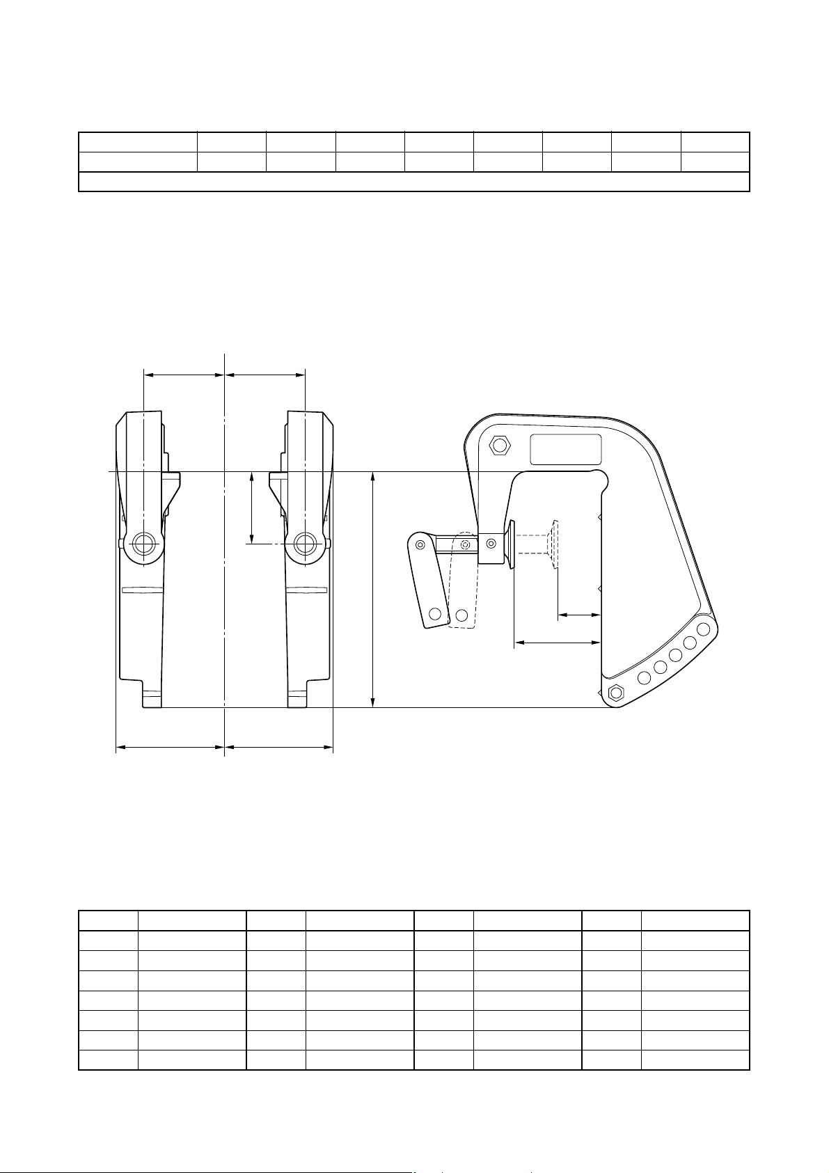
OUTBOARD MOTOR DIMENSIONS
C/L
B11
B11
B5
B5
B12
B6
C1
C2
CLAMP BRACKET DIMENSIONS
Global model 6C 8C
US/CA model
Manual tilt
Symbol mm (in.) Symbol mm (in.) Symbol mm (in.) Symbol mm (in.)
B1 — B8 — C1 22 (0.9) D1 —
B2 — B9 — C2 55 (2.2) D2 —
B3 — B10 — C3 — D3 —
B4 — B11 56 (2.2) D4 —
B5 75 (3.0) B12 50 (2.0)
B6 164.3 (6.5)
B7 —
1-32

OUTBOARD MOTOR DIMENSIONS
B6
B2
B9
B4
B1
B1
B5
C/L
B5
D2
D1
B3
B3
C1
B12
C2
CLAMP BRACKET DIMENSIONS
Global model F8C FT8D
US/CA model F8A
Manual tilt
Symbol mm (in.) Symbol mm (in.) Symbol mm (in.) Symbol mm (in.)
B1 70.5 (2.8) B8 — C1 32 (1.3) D1 8.3 (0.3)
B2 180.5 (7.1) B9 18 (0.7) C2 65 (2.6) D2 8.3 (0.3)
B3 95.3 (3.8) B10 — C3 — D3 —
B4 94.5 (3.7) B11 — D4 —
B5 105.3 (4.2) B12 48 (1.9)
B6 189.5 (7.4)
B7 —
1-33

OUTBOARD MOTOR DIMENSIONS
B6
B2
B9
B12
B1
B1
1
B3
B5
B1
B1
1
B3
B5
B4
C1
C2
D2
D1
C/L
CLAMP BRACKET DIMENSIONS
Global model 9.9F 15F
US/CA model
Manual tilt
Symbol mm (in.) Symbol mm (in.) Symbol mm (in.) Symbol mm (in.)
B1 92.5 (3.6) B8 — C1 30 (1.2) D1 8.3 (0.3)
B2 103.5 (4.1) B9 54.5 (2.1) C2 56 (2.2) D2 8.3 (0.3)
B3 92.5 (3.6) B10 — C3 — D3 —
B4 49 (1.9) B11 70.5 (2.8) D4 —
B5 102.5 (4.0) B12 69 (2.7)
B6 176 (6.9)
B7 —
1-34

OUTBOARD MOTOR DIMENSIONS
B5
C/L
B2
B11
B11
B12
B9
B1
B1
B5
D1
C3
C1
C2
B6
CLAMP BRACKET DIMENSIONS
Global model E9.9D E15D EK9.9D EK15D EK9.9J EK15P
US/CA model
Manual tilt
Symbol mm (in.) Symbol mm (in.) Symbol mm (in.) Symbol mm (in.)
B1 92.6 (3.6) B8 — C1 30 (1.2) D1 8.3 (0.32)
B2 79 (3.1) B9 107 (4.2) C2 60 (2.4) D2 —
B3 — B10 — C3 — D3 —
B4 — B11 67.3 (2.6) D4 —
B5 106.3 (4.2) B12 50 (2.0)
B6 157 (6.2)
B7 —
1-35

OUTBOARD MOTOR DIMENSIONS
C/L
B3
B11
B6
B4
B12
B5
B3
B11
B9
C1
C2
D1
CLAMP BRACKET DIMENSIONS
Global model F9.9H F15C F20B F20C F9.9J FT9.9L
US/CA model F15A F20A F9.9B T9.9B
Manual tilt
Symbol mm (in.) Symbol mm (in.) Symbol mm (in.) Symbol mm (in.)
B1 — B8 — C1 32 (1.3) D1 8.3 (0.33)
B2 — B9 18 (0.71) C2 67 (2.6) D2 —
B3 95.3 (3.8) B10 — C3 — D3 —
B4 76.5 (3.0) B11 70.5 (2.8) D4 —
B5 110 (4.3) B12 48 (1.9)
B6 187.5 (7.4)
B7 —
1-36

OUTBOARD MOTOR DIMENSIONS
C1
C2
B11
B1
D2
D1
D1
B9
B9
B3
B12
B4
B2
B6
B5
B11
B1
B3
B5
C/L
CLAMP BRACKET DIMENSIONS
Global model FT8D F15C F20B FT9.9L
US/CA model F15A F20A T9.9B
Power tilt
Symbol mm (in.) Symbol mm (in.) Symbol mm (in.) Symbol mm (in.)
B1 95.3 (3.8) B8 — C1 38 (1.5) D1 8.3 (0.3)
B2 275.5 (10.8) B9 18 (0.7) C2 67 (2.6) D2 10 (0.4)
B3 95.3 (3.8) B10 — C3 — D3 —
B4 94.5 (3.7) B11 73.5 (2.9) D4 —
B5 111 (4.4) B12 69.5 (2.7)
B6 325.5 (12.8)
B7 —
1-37

OUTBOARD MOTOR DIMENSIONS
B11
C/L
B3
B1
B5
C2
B2
B12
B4
D2
B6
C1
D1
B1
1
B3
B1
B5
D1
CLAMP BRACKET DIMENSIONS
Global model E/25B 25X E/30H EK25B EK25C
US/CA model
Manual tilt
Symbol mm (in.) Symbol mm (in.) Symbol mm (in.) Symbol mm (in.)
B1 89 (3.5) B8 — C1 35 (1.4) D1 8.5 (0.33)
B2 140 (5.5) B9 — C2 65 (2.6) D2 15 (0.59)
B3 112.5 (4.4) B10 — C3 — D3 —
B4 96.5 (3.8) B11 85 (3.3) D4 —
B5 122.5 (4.8) B12 51 (2.0)
B6 176 (6.9)
B7 —
1-38

OUTBOARD MOTOR DIMENSIONS
B5
C/L
B5
B11
B11
B2
B3
B3
B12
C1
C2
D1
B6
CLAMP BRACKET DIMENSIONS
Global model 20D 25N
US/CA model
Manual tilt
Symbol mm (in.) Symbol mm (in.) Symbol mm (in.) Symbol mm (in.)
B1 — B8 — C1 25 (1.0) D1 8.3 (0.32)
B2 97.5 (3.8) B9 — C2 65 (2.6) D2 —
B3 114.5 (4.5) B10 — C3 — D3 —
B4 — B11 87.5 (3.4) D4 —
B5 122.5 (4.8) B12 84 (3.3)
B6 175 (6.9)
B7 —
1-39

OUTBOARD MOTOR DIMENSIONS
C2
C1
B6
B9
B3
B1
1
B5
C/L
B4
B12
D1
B3
B1
1
B5
CLAMP BRACKET DIMENSIONS
Global model E/40X F25D
US/CA model F25A
Manual tilt
Symbol mm (in.) Symbol mm (in.) Symbol mm (in.) Symbol mm (in.)
B1 — B8 — C1 37 (1.5) D1 10.5 (0.41)
B2 — B9 50 (2.0) C2 68 (2.7) D2 —
B3 140 (5.5) B10 — C3 — D3 —
B4 32 (1.3) B11 95.5 (3.8) D4 —
B5 150 (5.9) B12 57 (2.2)
B6 218 (8.6)
B7 —
1-40

OUTBOARD MOTOR DIMENSIONS
C2
C1
B3
D2
D1
B1
1
B5
C/L
B2
B6
B12
B9
B4
B3
B1
1
B5
D1
CLAMP BRACKET DIMENSIONS
Global model E40G E40J EK40G EK40J
US/CA model
Manual tilt
Symbol mm (in.) Symbol mm (in.) Symbol mm (in.) Symbol mm (in.)
B1 — B8 — C1 33 (1.3) D1 10.5 (0.41)
B2 212 (8.3) B9 50 (2.0) C2 60 (2.3) D2 27 (1.1)
B3 124.5 (4.9) B10 — C3 — D3 —
B4 32 (1.3) B11 93.5 (3.7) D4 —
B5 134.5 (5.3) B12 57 (2.2)
B6 249 (9.8)
B7 —
1-41

OUTBOARD MOTOR DIMENSIONS
C3
B3
B5
C/L
B1
B4
B9
B2D2
B6
B9B9
D1
D1
B3
B5
B1
CLAMP BRACKET DIMENSIONS
Global model 30D E/40X F25D FT25F F30B F40F F20D
US/CA model F25A/B T25A F30A F40A
PTT & Hydro-tilt
Symbol mm (in.) Symbol mm (in.) Symbol mm (in.) Symbol mm (in.)
B1 126 (5.0) B8 — C1 — D1 13 (0.5)
B2 254 (10.0) B9 18.5 (0.7) C2 — D2 55.5 (2.2)
B3 163.5 (6.4) B10 — C3 69 (2.7) D3 —
B4 50.8 (2.0) B11 — D4 —
B5 180 (7.1) B12 —
B6 338 (13.3)
B7 —
1-42

OUTBOARD MOTOR DIMENSIONS
C3
B3
B5
C/L
B1
B4
B9
B2D2
B6
B9B9
D1
D1
B3
B5
B1
CLAMP BRACKET DIMENSIONS
Global model F40H F50H FT50J F60F FT60G F70A F40G
US/CA model F50B T50B F60B T60B F70A
PTT & Hydro-tilt
Symbol mm (in.) Symbol mm (in.) Symbol mm (in.) Symbol mm (in.)
B1 126 (5.0) B8 — C1 — D1 13 (0.5)
B2 254 (10.0) B9 18.5 (0.7) C2 — D2 55.5 (2.2)
B3 163.5 (6.4) B10 — C3 69 (2.7) D3 —
B4 50.8 (2.0) B11 — D4 —
B5 180 (7.1) B12 —
B6 350 (13.8)
B7 —
1-43

OUTBOARD MOTOR DIMENSIONS
B5
B6
B2
B9
B9
B9
D2
B7
B1
D1
B4
C3
D1
B3
B5
C/L
B7
B1
B3
D3
B
8
CLAMP BRACKET DIMENSIONS
Global model 40V 50H E60H F50D FT50C
US/CA model
PTT & Hydro-tilt
Symbol mm (in.) Symbol mm (in.) Symbol mm (in.) Symbol mm (in.)
B1 126 (5.0) B8 203 (8.0) C1 — D1 13 (0.51)
B2 254 (10.0) B9 18.5 (0.73) C2 — D2 60.5 (2.4)
B3 163.5 (6.4) B10 — C3 69 (2.7) D3 13 (0.51)
B4 50.8 (2.0) B11 — D4 —
B5 180 (7.1) B12 —
B6 355 (14.0)
B7 138 (5.4)
1-44

OUTBOARD MOTOR DIMENSIONS
B3
B1
1
B5
C/L
B6
B12
D2
B2
B4
B9
B9
D1
D1
B1
B3
B1
1
B5
B1
C1
C2
CLAMP BRACKET DIMENSIONS
Global model 30D 40V 50H
US/CA model
Manual tilt
Symbol mm (in.) Symbol mm (in.) Symbol mm (in.) Symbol mm (in.)
B1 62.5 (2.5) B8 — C1 30 (1.2) D1 10.5 (0.41)
B2 208 (8.2) B9 25 (0.98) C2 66 (2.6) D2 26 (1.0)
B3 121.5 (4.8) B10 — C3 — D3 —
B4 32 (1.3) B11 90.5 (3.6) D4 —
B5 131.5 (5.2) B12 57 (2.2)
B6 245 (9.6)
B7 —
1-45

OUTBOARD MOTOR DIMENSIONS
B11
C/L
B3
B1
B5
B11
B2
B6
B8
B12
D3
B3
B1
B5
D2
D1
C3
AN1
AN2
CLAMP BRACKET DIMENSIONS
Global model E48C E55C
US/CA model
Manual tilt
Symbol mm (in.) Symbol mm (in.) Symbol mm (in.) Symbol mm (in.)
B1 96 (3.8) B8 95 (3.7) C1 — AN1 14 (0.55)
B2 230 (9.1) B9 — C2 — AN2 12 (0.47)
B3 119 (4.7) B10 — C3 73 (2.9)
B4 — B11 96 (3.8) D1 12 (0.47)
B5 129 (5.1) B12 57 (2.2) D2 8 (0.31)
B6 254 (10.0) D3 10.5 (0.41)
B7 — D4 —
1-46

OUTBOARD MOTOR DIMENSIONS
B6
B8
B1
B7
D1
B3
B5
C/L
B2
D2
C3
D1
B4
B9
B9
B9
B1
B7
B3
B5
D3
AN1
AN2 AN2
CLAMP BRACKET DIMENSIONS
Global model 55B 60F E60H
US/CA model
PTT & Hydro-tilt for S-transom
Symbol mm (in.) Symbol mm (in.) Symbol mm (in.) Symbol mm (in.)
B1 125.4 (4.9) B8 203.2 (8.0) C1 — D1 13 (0.51)
B2 254 (10.0) B9 18.5 (0.73) C2 — D2 55.5 (2.2)
B3 163.5 (6.4) B10 — C3 68.5 (2.7)
B4 50.8 (2.0) B11 —
D3
Studbolt hole:
M12 × 1.25-40 deep
B5 180 (7.1) B12 — D4 —
B6 329 (13.0) AN1 19 (0.75)
B7 138.1 (5.4) AN2 101.5 (4.0)
1-47

OUTBOARD MOTOR DIMENSIONS
B6
B1
B7
D1
B3
B5
C/L
B2
B8
D2
C3
D1
B4
B9
B9
B9
B1
B7
B3
B5
D3
AN1
AN2 AN2
CLAMP BRACKET DIMENSIONS
Global model 55B 55D 60F 70B 75A 75C 85A 90A
US/CA model
Global model E60H E75B
US/CA model
PTT & Hydro-tilt for L/X-transom
Symbol mm (in.) Symbol mm (in.) Symbol mm (in.) Symbol mm (in.)
B1 125.4 (4.9) B8 203.2 (8.0) C1 — D1 13 (0.51)
B2 254 (10.0) B9 18.5 (0.73) C2 — D2 55.5 (2.2)
B3 163.5 (6.4) B10 — C3 68.5 (2.7)
B4 50.8 (2.0) B11 —
D3
Studbolt hole:
M12 × 1.25-40 deep
B5 180 (7.1) B12 — D4 —
B6 352 (13.9) AN1 19 (0.75)
B7 138.1 (5.4) AN2 101.5 (4.0)
1-48

OUTBOARD MOTOR DIMENSIONS
B6
B3
B1
D1
B5
C/L
B3
B1
B5
C3
B13
B2
D2
D1
B4
B9
B9
B9
AN1
AN2 AN2
CLAMP BRACKET DIMENSIONS
Global model F75B F80B F90B F100D
US/CA model F75A F90A
PTT
Symbol mm (in.) Symbol mm (in.) Symbol mm (in.) Symbol mm (in.)
B1 125.4 (4.9) B8 — C1 — AN1 19 (0.75)
B2 254 (10.0) B9 18.5 (0.73) C2 — AN2 101.5 (4.0)
B3 163.5 (6.4) B10 — C3 80 (3.1)
B4 50.8 (2.0) B11 — D1 13 (0.51)
B5 180 (7.1) B12 — D2 55.5 (2.2)
B6 368 (14.5) B13 20 (0.79) D3 —
B7 — D4 —
1-49

OUTBOARD MOTOR DIMENSIONS
B13
B5
C/L
B3B3
B6
B1
B2
D1
C3
D1
D2
B4
B9
B9B9
B5
B1
AN1
AN2 AN2
CLAMP BRACKET DIMENSIONS
Global model E115A 115B 115C 130B 140B L/150A 150G Z150Q
US/CA model VZ150
Global model L/200A F75C F95A F100B
US/CA model
Global model
US/CA/ANZ model
F/FL150A F/FL150B
F/LF150A
F225C
PTT & Hydro tilt
F/FL115A
F/LF115A
Symbol mm (in.) Symbol mm (in.) Symbol mm (in.) Symbol mm (in.)
B1 125.4 (4.9) B8 — C1 — AN1 52 (2.0)
B2 254 (10.0) B9 18.5 (0.73) C2 — AN2 102 (4.0)
B3 163.5 (6.4) B10 — C3 82 (3.2)
B4 50.8 (2.0) B11 — D1 13 (0.51)
B5 180 (7.1) B12 — D2 55.5 (2.2)
B6 367 (14.4) B13 24 (0.94) D3 —
B7 — D4 —
1-50

OUTBOARD MOTOR DIMENSIONS
CLAMP BRACKET DIMENSIONS
Global model
US/CA/ANZ model
PTT
B2
F/FL115B
F/LF115B
C/L
B3 B3
B6
B5B5
C3
B9 B4
D1
D2
AN1
D1
AN2AN2
B1
B1
D1
B13
Symbol mm (in.) Symbol mm (in.) Symbol mm (in.) Symbol mm (in.)
B1 125.4 (4.9) B8 — C1 — AN1 17 (0.7)
B2 254 (10.0) B9 18.5 (0.73) C2 — AN2 101.5 (4.0)
B3 163.5 (6.4) B10 — C3 82 (3.2)
B4 50.8 (2.0) B11 — D1 13 (0.51)
B5 180 (7.1) B12 — D2 55.5 (2.2)
B6 357.2 (14.1) B13 20 (0.79) D3 —
B7 — D4 —
1-51

OUTBOARD MOTOR DIMENSIONS
CLAMP BRACKET DIMENSIONS
Global model
US/CA/ANZ model
PTT
B4
B9
D1
F175A F/FL200F
F175A F/LF200B
B5 B5
B3 B3
C/L
F/FL200G
F/LF200CA
C3
B2
B6
D2
AN1
AN2AN2
B1 B1
D1
B13
Symbol mm (in.) Symbol mm (in.) Symbol mm (in.) Symbol mm (in.)
B1 125.4 (4.9) B8 — C1 — AN1 25 (1.0)
B2 254 (10.0) B9 18.5 (0.73) C2 — AN2 102 (4.0)
B3 163.5 (6.4) B10 — C3 82 (3.2)
B4 50.8 (2.0) B11 — D1 13 (0.51)
B5 180 (7.1) B12 — D2 55.5 (2.2)
B6 367 (14.4) B13 24 (0.94) D3 —
B7 — D4 —
1-52

OUTBOARD MOTOR DIMENSIONS
CLAMP BRACKET DIMENSIONS
Global model F150C F165A F200D F225D F250C F225G F250F F275A
US/CA/ANZ model
PTT
VF150A VF200A VF225A VF250A
B6
B9
AN1
B4
D1
B5 B5
B3 B3
C/L
AN2AN2
B1 B1
D1
C3
B2
D2
B13
Symbol mm (in.) Symbol mm (in.) Symbol mm (in.) Symbol mm (in.)
B1 125.4 (4.9) B8 — C1 — AN1 13.5 (0.5)
B2 254 (10.0) B9 18.5 (0.7) C2 — AN2 —
B3 163.5 (6.4) B10 — C3 82 (3.2)
B4 50.8 (2.0) B11 — D1 13 (0.5)
B5 180 (7.1) B12 — D2 55.5 (2.2)
B6 368 (14.5) B13 20 (0.79) D3 —
B7 — D4 —
1-53

OUTBOARD MOTOR DIMENSIONS
CLAMP BRACKET DIMENSIONS
Global model L/250G
US/CA/ANZ model
Global model
F/FL300B
US/CA/ANZ model F/LF300CA
PTT
B5 B5
B3 B3
C/L
F/FL200B F/FL200C F/FL225B F/FL250A F/FL250G F/FL225F F/FL250D
F/LF200A F/LF225A F/LF250A
B4
B9B9 B9
B2D2
D1
C3
B13
F/LF225CA F/LF250CA
B6AN1
AN2 AN2
D1
B1
B1
Symbol mm (in.) Symbol mm (in.) Symbol mm (in.) Symbol mm (in.)
B1 125.4 (4.9) B8 — C1 — AN1 52 (2.0)
B2 254 (10.0) B9 18.5 (0.7) C2 — AN2 102 (4.0)
B3 163.5 (6.4) B10 — C3 79 (3.1)
B4 50.8 (2.0) B11 — D1 13 (0.5)
B5 180 (7.1) B12 — D2 55.5 (2.2)
B6 411 (16.2) B13 20 (0.79) D3 —
B7 — D4 —
1-54

OUTBOARD MOTOR DIMENSIONS
B5
B3
B5
B3
B13
B2
B4
D1
B1
B1
C/L
B9
AN2
AN2
D2
AN1
B6
D1
B9 B9 B9 B9
CLAMP BRACKET DIMENSIONS
Global model
US/CA/ANZ model
PTT
F/FL350A
F/LF350CB
Symbol mm (in.) Symbol mm (in.) Symbol mm (in.) Symbol mm (in.)
B1 125.4 (4.9) B8 — C1 — AN1 19 (0.75)
B2 254 (10.0) B9 18.5 (0.73) C2 — AN2 102 (4.0)
B3 163.5 (6.4) B10 — C3 —
B4 50.8 (2.0) B11 — D1 13 (0.51)
B5 180 (7.1) B12 — D2 92.6 (3.6)
B6 406 (16.0) B13 21 (0.83) D3 —
B7 — D4 —
1-55

MEMO

PROPELLERS
PROPELLER SPECIFICATIONS ............................................................. 2-2
PROPELLER TYPES ...........................................................................2-2
PROPELLER IDENTIFICATION........................................................... 2-5
PROPELLER SELECTION.......................................................................2-6
2014 PROPELLER APPLICATIONS........................................................ 2-6
STANDARD PROPELLER ................................................................... 2-6
STANDARD PROPELLERS (Shift Dampener System [SDS]) ........... 2-12
DUAL THRUST PROPELLERS.......................................................... 2-13
WEEDLESS PROPELLERS............................................................... 2-14
RELIANCE SERIES PROPELLERS (STD) ........................................ 2-14
RELIANCE SERIES PROPELLERS
(Shift Dampener System [SDS]) .................................................... 2-15
SALTWATER SERIES PROPELLERS............................................... 2-16
SALTWATER SERIES II PROPELLERS (STD)................................. 2-17
SALTWATER SERIES II PROPELLERS
(Shift Dampener System [SDS]) .................................................... 2-18
SALTWATER SERIES HS4 PROPELLERS (STD) ............................ 2-19
SALTWATER SERIES HS4 PROPELLERS
(Shift Dampener System [SDS]) .................................................... 2-19
SALTWATER SERIES XL PROPELLERS
(Shift Dampener System [SDS]) .................................................... 2-20
SALTWATER SERIES XL4 PROPELLERS
(Shift Dampener System [SDS]) .................................................... 2-20
VMAX SERIES PROPELLERS .......................................................... 2-21
PERFORMANCE SERIES PROPELLERS......................................... 2-21
HIGH PERFORMANCE SERIES PROPELLERS............................... 2-22
WOT OPERATION RANGE TABLE....................................................... 2-23
2-1

PROPELLER SPECIFICATIONS
PROPELLER TYPES
Yamaha propellers are specifically designed to
match the characteristics of Yamaha outboard
motors.
There are some types of propellers for the best
matching depending on the operating condition.
Major types of propellers include:
STANDARD
This propeller series is designed for general
use to match a wide range of operating conditions.
A stainless steel or an aluminum propeller can
be selected to suit the preference of the user.
A stainless steel, counter rotation propeller is
available for twin engine applications.
The aluminum, regular rotation propeller with
SDS (Shift Dampener System) is now
designed to match the K-series fitting boss.
RELIANCE SERIES
New polished stainless steel propellers are
designed to provide for 150PS and bigger
standard type engines.
These propellers are generally more aggressive than black standard stainless steel propellers, and will fit the engines under almost all
operating conditions.
L/H rotation propellers are available for twinengine applications.
SALTWATER SERIES II
This new breed of stainless steel props is
designed exclusively for offshore fishing boats
and features highly polished, larger diameter
design. The aggressive rake angle and extra
cupping on the blades provide superior midrange fuel efficiency, along with excellent anticavitation performance.
Shift Dampener System (SDS) has been
adopted to reduce the shock and noise when
shifting, and become possible to replace the
propeller damper.
L/H rotation propellers are available for twinengine applications.
2-2

PROPELLER SPECIFICATIONS
SALTWATER SERIES XL
New polished stainless steel propellers have
been designed for big offshore boats to obtain
big impulsion power.
It features large diameter blade design, especially for F350 engine.
Shift Dampener System (SDS) has been
adopted to reduce the shock and noise when
shifting, and become possible to replace the
propeller damper.
L/H rotation propellers are available for multiengine applications.
SALTWATER SERIES HS4
Polished stainless steel propellers with 4-blade
for V6-3.1L, 3.3L and 4.2L engines, except for
VMAX series.
Compared with the conventional three blades
propeller, four blades make larger propeller
blade surface area, which can catch much
more water and obtain higher thrust performance.
As a result, this propeller will obtain better
acceleration, and stable operation under rough
water.
However, generally boat top speed performance is slightly lower than three blades propeller.
Shift Dampener System (SDS) has been
adopted to reduce the shock and noise when
shifting, and it is possible to replace the propeller damper.
L/H rotation propellers are available for twin
application.
2-3

PROPELLER SPECIFICATIONS
SALTWATER SERIES XL4
Designed for the V8 F350 5.3L four stroke
only, this stainless steel four blade prop is
intended for large offshore boats—such as
express cruisers or walk arounds—that require
massive thrust-to-plane and additional propeller grip for maximum operational efficiency.
Made of highly polished stainless steel and
available with our patent-pending Shift Dampener System (SDS).
* Shift Dampener System (SDS):
Using a special new design and high-strength
components, much of the resulting force of an
outboard shifting into forward or reverse gear is
absorbed, resulting in far quieter and smoother
operation.
PERFORMANCE
These stainless steel propellers with vents for
exhaust gas induction offer the best acceleration and top end performance causing the
engine rpm rapidly increasing with a high rake,
progressive pitch and more cup.
It allows higher transom mounting such as bass
boats, yet does not increase steering torque.
PROPELLER SPECIFICATIONS
HIGH PERFORMANCE
With the progressive pitch design and highly
cupped blades, these special small hub propellers are designed for high-performance runabout boats.
The through-hub exhaust system allows the
exhaust gas to outlet the leading edge of each
blade for enhanced acceleration.
VMAX SERIES
These polished stainless steel propellers are
designed for a high-speed and light weight
special boat with high-power engine for better
performance.
These specialized propellers are generally more
aggressive than the ventilated type propellers.
WEEDLESS
This is designed for use in shallow water.
It eliminates weed buildup around the propeller
hub.
2-4

PROPELLER SPECIFICATIONS
Pitch
Diameter
REAR VIEW
4
FRONT
VIEW
3
2
1
5
DUAL THRUST
This is designed for sailboat or other large displacement boats.
This redirects the exhaust gases so that the
blades cut through “clean” water, for higher
efficiency.
PROPELLER IDENTIFICATION
The propeller identification of the size is indicated as follows.
Propeller
identification
Diameter: Diameter of propeller rotating circle.
Pitch: Logical advancing distance when
propeller rotated one time.
The location of the propeller identification varies.
Refer to the illustration as shown.
Diameter
=
(inch)
X
Pitch
(inch)
–Mark
Example:
(1) 7-1/4 X 6 - BS
(2) 21 - ML (Pitch - Mark)
(3) 13 X 17 - K2
(4) 19K (Pitch and Mark)
(5) 9-1/4 X 9 - J
* Calculation formula of the logical boat speed is as
below.
^ Boat speed (km/h) = propeller pitch (inch) X
engine speed (r/min) X 0.001524 X propeller
efficiency / gear ratio.
^ Propeller efficiency = Actual advancing dis-
tance when propeller rotated one time / Logical
advancing distance when propeller rotated one
time.
2-5

PROPELLER SELECTION
Depending on the model, Yamaha outboard motors are fitted with the propellers which are chosen
to perform well over a range of applications, but there may be the uses where a propeller with a different pitch would be more appropriate.
For a greater operating load, a smaller pitch propeller is more suitable as enables the correct engine
speed at WOT (Wide-Open-Throttle) to be maintained.
Conversely, a larger pitch propeller is more suitable for a smaller operating load.
For details, see the WOT operation range table in this chapter.
Besides, select the best matched propeller series that meet the purpose of use depending on the
classification and/or type of boat.
2014 PROPELLER APPLICATIONS
STANDARD PROPELLER
2 ps
Global model 2C
US/CA model
Blade Dia. (in) Pitch (in) Mark Material Part number Remarks
3 7 1/4 4 A Plastic 6A1-45943-00 Fitted with shear pin
3 7 1/4 4 1/2 A Aluminum 646-45944-01 Fitted with shear pin
3 7 1/4 5 A Aluminum 6F8-45942-01 Fitted with shear pin
3 7 1/4 5 1/2 A Aluminum 646-45942-01 Fitted with shear pin
2 – 3 ps
Global model F2A F2.5A 3A
US/CA model F2.5A
Blade Dia. (in) Pitch (in) Mark Material Part number Remarks
3 7 1/4 5 BS Aluminum 6L5-45949-00
3 7 1/4 5 1/2 BS Aluminum 6L5-45952-00
3 7 1/4 6 BS Aluminum 6L5-45943-00
3 7 1/4 7 1/4 BS Aluminum 6L5-45945-00
3 7 1/4 8 1/4 BS Aluminum 6L5-45947-00
* Use the thrust washer (68D-G5987-00) for 4-stroke mode, and (6L5-45987-01) for 2-stroke model.
4 – 6 ps
Global model 4AC 5C 5CS F4B F5A 5CM F6C
US/CA model F4A F6A
Blade Dia. (in) Pitch (in) Mark Material Part number Remarks
3 7 1/4 6 1/2 BA Aluminum 6E0-45949-00
3 7 1/2 7 BA Aluminum 6E0-45943-01
3 7 1/2 8 BA Aluminum 6E0-45941-01
3 7 1/4 8 1/4 BA Aluminum 6E0-45952-00
3 7 1/2 9 BA Aluminum 6E0-45954-00
2-6

2014 PROPELLER APPLICATIONS
STANDARD PROPELLER
8 ps
Global model E8D EK8D
US/CA model
Blade Dia. (in) Pitch (in) Mark Material Part number Remarks
3 7 1/4 5 C Aluminum 655-45949-00 Fitted with shear pin
3 9 5 3/4 C Aluminum 655-45947-01 Fitted with shear pin
3 9 6 1/2 C Aluminum 655-45945-00 Fitted with shear pin
3 9 7 C Aluminum 647-45943-00 Fitted with shear pin
3 9 7 1/2 C Aluminum 655-45943-00 Fitted with shear pin
3 9 9 C Aluminum 647-45947-00 Fitted with shear pin
3 9 1/4 9 1/4 C Aluminum 647-45941-00 Fitted with shear pin
6 – 9.9 ps
Global model 6C 8C F8C F9.9J
US/CA model F8A F9.9B
Blade Dia. (in) Pitch (in) Mark Material Part number Remarks
3 8 1/2 6 1/2 N Aluminum 6G1-45947-00
3 8 1/2 7 1/2 N Aluminum 6G1-45943-00
3 8 1/2 8 N Aluminum 6G1-45952-00
3 8 1/2 8 1/2 N Aluminum 6G1-45941-00
3 8 1/2 9 1/4 N Aluminum 6G1-45954-00
9.9 – 15 ps
Global model 9.9F 15F E9.9D E15D EK9.9J EK15P EK9.9D EK15D
US/CA model
Global model F9.9H F15C
US/CA model F15A
Blade Dia. (in) Pitch (in) Mark Material Part number Remarks
3 9 1/2 6 1/2 J Aluminum 683-45949-00
3 9 1/4 8 J Aluminum 63V-45947-00
3 9 1/4 9 3/4 J Aluminum 683-45952-00
3 9 1/4 10 J Aluminum 63V-45952-00
3 9 1/4 10 1/2 J Aluminum 683-45943-00
3 9 1/4 11 J Aluminum 63V-45943-00
3 9 1/4 12 J Aluminum 683-45941-00
* Use the thrust washer (6B8-45987-00) for kerosene model, avoiding propeller damper damage.
9.9 – 20 ps
Global model F9.9H F15C F20B F20C
US/CA model F15A F20A
Blade Dia. (in) Pitch (in) Mark Material Part number Remarks
3 9 1/4 9 J1 Aluminum 63V-45945-10
3 9 1/4 10 J1 Aluminum 63V-45952-10
3 9 1/4 11 J1 Aluminum 63V-45943-10
3 9 1/4 12 J1 Aluminum 63V-45941-10
2-7

2014 PROPELLER APPLICATIONS
STANDARD PROPELLER
20 – 30 ps
Global model 20D 25N E/25B 25X E/30H
US/CA model F25A/B
Global model F20D
US/CA model
Blade Dia. (in) Pitch (in) Mark Material Part number Remarks
3 9 7/8 8 F Aluminum 664-45943-01
3 9 7/8 9 F Aluminum 664-45941-01
3 9 7/8 10 F Aluminum 62C-45941-00
3 9 7/8 10 1/2 F Aluminum 664-45945-00
3 9 7/8 11 1/4 F Aluminum 664-45947-01
3 9 7/8 12 F Aluminum 664-45954-01
3 9 7/8 13 F Aluminum 664-45949-02
3 9 7/8 14 F Aluminum 664-45952-00
3 9 7/8 12 F S-Steel 664-45973-00
3 9 7/8 13 F S-Steel 664-45971-00
EK25B/C
30D F25D
FT/T25 & 30 – 60 ps
Global model 40V 50H E40J EK40J E/40X E48C E55C 55B
US/CA model
Global model FT25F F30B F40F F50D F40H F50H F60H 40X
US/CA model T25A F30A F40A F50B F60B
Blade Dia. (in) Pitch (in) Mark Material Part number Remarks
3 12 1/4 8 G Aluminum 63D-45941-00
3 12 1/4 9 G Aluminum 663-45956-01
3 11 3/4 10 G Aluminum 663-45954-01
3 11 5/8 11 G Aluminum 69W-45947-00
3 10 5/8 12 G Aluminum 6H5-45952-00
3 11 3/8 12 G Aluminum 663-45952-02
3 11 3/8 12 G Aluminum 69W-45952-00
3 10 3/8 13 G Aluminum 6H5-45945-00
3 11 1/8 13 G Aluminum 69W-45945-00
3 10 1/4 14 G Aluminum 6H5-45958-00
3 11 1/4 14 G Aluminum 69W-45958-00
3 11 1/4 14 G Aluminum 663-45958-01
3 10 15 G Aluminum 6H5-45943-00
3 11 15 G Aluminum 69W-45943-00
3 10 3/4 16 G Aluminum 663-45949-01
3 10 3/4 17 G Aluminum 663-45941-01
3 12 11 G S-Steel 663-45972-60
3 11 3/4 12 G S-Steel 663-45970-60
3 11 1/2 13 G S-Steel 663-45974-60
3 10 1/4 14 G S-Steel 663-45930-00
3 11 1/4 14 G S-Steel 697-45970-00
3 10 1/4 15 G S-Steel 663-45976-00
3 10 1/4 16 G S-Steel 663-45978-00
2-8

2014 PROPELLER APPLICATIONS
STANDARD PROPELLER
40 ps
Global model E40G EK40G
US/CA model
Blade Dia. (in) Pitch (in) Mark Material Part number Remarks
3 11 3/4 7 1/2 H Aluminum 676-45956-61 Fitted with drive pin
3 11 3/4 8 3/4 H Aluminum 676-45947-62 Fitted with drive pin
3 11 3/4 10 H Aluminum 676-45945-62 Fitted with drive pin
3 11 1/2 11 H Aluminum 676-45941-62 Fitted with drive pin
3 11 1/2 12 H Aluminum 676-45943-62 Fitted with drive pin
3 11 1/2 13 H Aluminum 676-45952-62 Fitted with drive pin
3 11 1/2 13 1/2 H Aluminum 676-45949-62 Fitted with drive pin
55 – 115 ps
Global model 60F 70B E60H 55D 75A E75B
US/CA model
Global model 85A 75C 90A 115C 130B E115A 115B 140B
US/CA model
Global model F40G FT50C FT50J FT60G F70A F75B F75C F80B
US/CA model T50B T60B F70A F75A
Global model F90B F95A F100B F100D F115A
US/CA model F90A F115A
Global model F115B
US/CA/ANZ model F115B
Blade Dia. (in) Pitch (in) Mark Material Part number Remarks
3 14 11 K Aluminum 6E5-45954-00
3 13 5/8 13 K Aluminum 6E5-45949-00
3 13 5/8 14 K Aluminum 6E5-45958-00
3 13 1/2 15 K Aluminum 6E5-45947-00
3 13 1/4 17 K Aluminum 6E5-45945-01
3 13 19 K Aluminum 6E5-45941-00
3 12 5/8 21 K Aluminum 6E5-45943-00
3 13 23 K Aluminum 6E5-45952-00
3 13 25 K Aluminum 6E5-45956-00
3 13 1/2 14 K S-Steel 688-45932-60
3 13 1/2 16 K S-Steel 688-45978-60
3 13 17 K S-Steel 688-45930-02
3 13 19 K S-Steel 688-45970-03
3 13 21 K S-Steel 688-45972-02
3 13 23 K S-Steel 688-45974-02
3 13 25 K S-Steel 688-45976-01
L115 ps
Global model FL115A
US/CA model LF115A
Global model FL115B
US/CA/ANZ model LF115B
Blade Dia. (in) Pitch (in) Mark Material Part number Remarks
3 13 17 KL S-Steel 6L6-45930-01
3 13 19 KL S-Steel 6L6-45970-00
3 13 21 KL S-Steel 6L6-45972-00
2-9

2014 PROPELLER APPLICATIONS
STANDARD PROPELLER
150 – 200 ps
Global model 150A 200A
US/CA model
Global model F150A F150B F200B F200C F200F F200G
US/CA/ANZ model F150A F200A F200B F200CA
Blade Dia. (in) Pitch (in) Mark Material Part number Remarks
3 15 1/4 15 M Aluminum 6G5-45941-00
3 14 5/8 16 M Aluminum 6G5-45952-00
3 14 1/2 17 M Aluminum 6G5-45947-01
3 14 19 M Aluminum 6G5-45945-01
3 13 3/4 21 M Aluminum 6G5-45943-01
3 13 1/2 23 M Aluminum 6G5-45949-00
L150 – L200 ps
Global model L150A L200A
US/CA model
Global model FL150A FL150B FL200B FL200C FL200F FL200G
US/CA/ANZ model LF150A LF200A LF200B
Blade Dia. (in) Pitch (in) Mark Material Part number Remarks
3 14 1/2 17 ML Aluminum 6K1-45947-00
3 14 19 ML Aluminum 6K1-45945-00
LF200CA
150 – 250 ps
Global model 150A 200A 250G
US/CA model
Global model F150A F150B F200B F200C F200F F200G F225B F225C
US/CA/ANZ model F150A F200A F200B
Global model F250A F250G
US/CA/ANZ model F250A
Blade Dia. (in) Pitch (in) Mark Material Part number Remarks
3 15 3/4 13 M S-Steel 6G5-45932-00
3 15 1/4 15 M S-Steel 6G5-45970-02
3 13 3/4 17 M2 S-Steel 6G5-45978-03
3 13 3/4 19 M2 S-Steel 6G5-45974-03
3 13 3/4 21 M S-Steel 6G5-45972-02
3 13 3/8 23 M S-Steel 6G5-45976-01
3 13 3/8 25 M S-Steel 6G5-45930-00
F200CA
F225A
2-10

2014 PROPELLER APPLICATIONS
STANDARD PROPELLER
L150 – L250 ps
Global model L150A L200A L250G
US/CA model
Global model FL150A FL150B FL200B FL200C FL200F FL200G FL225B FL250A
US/CA/ANZ model LF150A LF200A LF200F
Global model FL250G
US/CA/ANZ model
Blade Dia. (in) Pitch (in) Mark Material Part number Remarks
3 15 1/4 15 ML S-Steel 6K1-45970-01
3 13 3/4 17 ML1 S-Steel 6K1-45978-02
3 13 3/4 19 ML1 S-Steel 6K1-45974-02
3 13 3/4 21 ML S-Steel 6K1-45972-01
3 13 3/8 23 ML S-Steel 6K1-45976-00
LF200CA
200 – 250 ps
Global model 250G
US/CA model
Global model F200B F200C F225B F225C F250A F250G
US/CA/ANZ model F200A F225A F250A
Blade Dia. (in) Pitch (in) Mark Material Part number Remarks
3 15 17 T S-Steel 61A-45978-00
3 14 1/2 19 T S-Steel 61A-45974-00
3 14 1/2 21 T S-Steel 61A-45972-00
LF225A LF250A
L200 – L250 ps
Global model L250G
US/CA model
Global model FL200B FL200C FL225B FL250A FL250G
US/CA/ANZ model LF200A LF225A LF250A
Blade Dia. (in) Pitch (in) Mark Material Part number Remarks
3 15 17 TL S-Steel 61B-45978-00
3 14 1/2 19 TL S-Steel 61B-45974-00
3 14 1/2 21 TL S-Steel 61B-45972-00
2-11

2014 PROPELLER APPLICATIONS
STANDARD PROPELLERS (Shift Dampener System [SDS])
55 – 115 ps
Global model 55D 60F E60H 70B 75A E75B 75C 85A
US/CA model
Global model 90A E115A 115B 115C 130B 140B F40G FT50C
US/CA model
Global model FT50J FT60G F70A F75B F75C F80B F90B F95A
US/CA model T50B T60B T70A F75A F90A
Global model F100B F100D
US/CA model
Global model
US/CA/ANZ model
Blade Dia. (in) Pitch (in) Mark Material Part number Remarks
3 13 1/2 9 K Aluminum 6EK-45941-00
3 13 1/2 10 1/2 K Aluminum 6EK-45943-00
3 13 1/2 12 K Aluminum 6EK-45945-00
3 13 1/2 14 K Aluminum 6EK-45947-00
3 13 1/4 16 K Aluminum 6EK-45949-00
F115B
F115B
F115A
F115A
2-12

2014 PROPELLER APPLICATIONS
DUAL THRUST PROPELLERS
6 – 9.9 ps
Global model 6C 8C F8C F9.9J
US/CA model F8A F9.9B
Blade Dia. (in) Pitch (in) Mark Material Part number Remarks
3 9 5 N Aluminum 6G1-W4592-00
3 9 7 N Aluminum 6G1-W4591-01
8 – 9.9 ps
Global model FT8D FT9.9L
US/CA model T9.9B
Blade Dia. (in) Pitch (in) Mark Material Part number Remarks
3 11 3/4 5 3/4 R Aluminum 69G-45941-00
3 11 3/4 7 R Aluminum 69G-45943-00
3 11 3/4 9 1/4 R Aluminum 6G8-45947-00
9.9 – 15 ps
Global model 9.9F 15F E9.9D E15D EK9.9J EK15P EK9.9D EK15D
US/CA model
Global model F9.9H F15C
US/CA model F15A
Blade Dia. (in) Pitch (in) Mark Material Part number Remarks
3 9 3/4 6 1/2 J Aluminum 683-W4592-02
3 9 3/4 8 J Aluminum 683-W4591-02
* Use the thrust washer (6B8-45987-00) for kerosene model, avoiding propeller damper damage.
20 – 30 ps
Global model 30D F25D E25B 30H E30H
US/CA model F25A
Blade Dia. (in) Pitch (in) Mark Material Part number Remarks
3 10 5/8 8 1/4 F Aluminum 6J8-W4591-00 For PT/PTT/Hydro model.
25 ps
Global model FT25F
US/CA model T25A
Blade Dia. (in) Pitch (in) Mark Material Part number Remarks
3 12 1/4 9 G Aluminum 68U-45941-00
50 – 70 ps
Global model FT50C FT50J FT60G F70A
US/CA model T50B T60B F70A
Blade Dia. (in) Pitch (in) Mark Material Part number Remarks
3 14 11 K Aluminum 68S-45941-00
2-13

2014 PROPELLER APPLICATIONS
WEEDLESS PROPELLERS
4 – 6 ps
Global model 4AC 5C/S F4B F5A F6C
US/CA model F4A F6A
Blade Dia. (in) Pitch (in) Mark Material Part number Remarks
3 7 1/4 8 1/4 BA Aluminum 6E0-45952-00
20 – 30 ps
Global model 20D 25N E/25B 25X E/30H
US/CA model F25A
Global model F20D
US/CA model
Blade Dia. (in) Pitch (in) Mark Material Part number Remarks
3 9 1/8 12 F S-Steel 664-45972-00
3 9 1/8 13 F S-Steel 664-45970-00
EK25B/C
30D F25D
RELIANCE SERIES PROPELLERS (STD)
150 – 250 PS
Global model 150A 200A 250G
US/CA model
Global model F150A/B F200B F200C F225B F225C F250A F250G
US/CA/ANZ model F150A F200A F225A F250A
Blade Dia. (in) Pitch (in) Mark Material Part number Remarks
3 14 1/4 17 M S-steel 68F-45972-10
3 14 1/4 18 M S-steel 68F-45978-10
3 13 3/4 19 M S-steel 68F-45974-10
3 13 3/4 21 M S-steel 68F-45976-10
L150 – L250 ps
Global model L150A L200A L250G
US/CA model
Global model
US/CA/ANZ model LF150A LF200A LF225A LF250A
Blade Dia. (in) Pitch (in) Mark Material Part number Remarks
3 14 1/4 17 ML S-steel 68G-45972-10
3 14 1/4 18 ML S-steel 68G-45978-10
3 13 3/4 19 ML S-steel 68G-45974-10
3 13 3/4 21 ML S-steel 68G-45976-10
FL150A/B
FL200B FL200C FL225B FL250A FL250G
2-14

2014 PROPELLER APPLICATIONS
RELIANCE SERIES PROPELLERS (Shift Dampener System [SDS])
150 – 300 PS
Global model 150A 200A 250G
US/CA model
Global model F150A/B F200B F200C F200F F200G F225B F225C F225F
US/CA/ANZ model F150A F200A F200B F200CA F225A F225CA
Global model F250A F250D F250G F300B
US/CA/ANZ model F250A F250CA F300CA
Blade Dia. (in) Pitch (in) Mark Material Part number Remarks
3 14 1/2 15 M S-steel 68F-45970-10
3 14 1/4 17 M S-steel 68F-45972-10
3 14 1/4 18 M S-steel 68F-45978-10
3 13 3/4 19 M S-steel 68F-45974-10
3 13 3/4 21 M S-steel 68F-45976-10
* Shift Dampener System (SDS) propeller requires the exclusive spacer (P/N: 6CE-45997-00).
L150 – L300 ps
Global model L150A L200A L250G
US/CA model
Global model
US/CA/ANZ model LF150A LF200A LF200B
Global model FL250G FL250D FL300B
US/CA/ANZ model
Blade Dia. (in) Pitch (in) Mark Material Part number Remarks
3 14 1/2 15 ML S-steel 68G-45970-10
3 14 1/4 17 ML S-steel 68G-45972-10
3 14 1/4 18 ML S-steel 68G-45978-10
3 13 3/4 19 ML S-steel 68G-45974-10
3 13 3/4 21 ML S-steel 68G-45976-10
* Shift Dampener System (SDS) propeller requires the exclusive spacer (P/N: 6CE-45997-00).
FL150A/B
FL200B FL200C FL200F FL200G FL225B FL225F FL250A
LF200CA
LF250CA FL300CA
LF225A
LF225CA
LF250A
2-15

2014 PROPELLER APPLICATIONS
SALTWATER SERIES PROPELLERS
150 – 250 ps
Global model 150A 200A
US/CA model
Global model F150A/B 250G F200B F200C F225B F225C F250A F250G
US/CA/ANZ model F150A F200A F225A F250A
Blade Dia. (in) Pitch (in) Mark Material Part number Remarks
3 15 1/4 15 M S-Steel 6R4-45976-A0
3 15 1/4 17 M S-Steel 6R4-45978-A0
3 15 1/4 19 M S-Steel 6R4-45970-A1
3 14 7/8 21 M S-Steel 6R4-45972-A0
3 14 1/2 23 M S-Steel 6R4-45974-A0
L150 – L250 ps
Global model L150A L200A L250G
US/CA model
Global model
US/CA/ANZ model LF150A LF200A LF225A LF250A
Blade Dia. (in) Pitch (in) Mark Material Part number Remarks
3 15 1/4 15 ML S-Steel 6R1-45976-A0
3 15 1/4 17 ML S-Steel 6R1-45978-A0
3 15 1/4 19 ML S-Steel 6R1-45970-A1
3 14 7/8 21 ML S-Steel 6R1-45972-A0
3 14 1/2 23 ML S-Steel 6R1-45974-A0
FL150A/B
FL200B FL200C FL225B FL250A FL250G
2-16

2014 PROPELLER APPLICATIONS
SALTWATER SERIES II PROPELLERS (STD)
150 – 300 ps
Global model 200A 250G
US/CA model
Global model F150A/B F200B F200C F225B F225C F250A F250B F250G
US/CA/ANZ model F150A F200A F225A F250A
Blade Dia. (in) Pitch (in) Mark Material Part number Remarks
3 15 3/4 15 T S-Steel 6D0-45976-00 For V6 3.1/3.3L model.
3 15 1/2 17 T S-Steel 6D0-45978-00
3 15 1/4 19 T S-Steel 6D0-45970-00
3 15 21 T S-Steel 6D0-45972-00
3 14 3/4 23 T S-Steel 6D0-45974-00
(*1) The blade contacts 6J9 lower-case.
L150 – L300 ps
Global model L150A L200A L250G
US/CA model
Global model
US/CA/ANZ model LF150A LF200A LF200B LF225A LF250A
Blade Dia. (in) Pitch (in) Mark Material Part number Remarks
3 15 3/4 15 TL S-Steel 6D1-45976-00 For V6 3.1/3.3L model.
3 15 1/2 17 TL S-Steel 6D1-45978-00
3 15 1/4 19 TL S-Steel 6D1-45970-10
3 15 21 TL S-Steel 6D1-45972-10
3 14 3/4 23 TL S-Steel 6D1-45974-00
(*1) The blade contacts 6J9 lower-case.
FL150A/B
FL200B FL200C FL200F FL225B FL250A FL250G
(*1)
(*1)
2-17

2014 PROPELLER APPLICATIONS
SALTWATER SERIES II PROPELLERS (Shift Dampener System [SDS])
150 – 300 ps
Global model 150A 200A 250G
US/CA model
Global model F150A/B F175A F200B F200C F200F F200G F225B F225C
US/CA/ANZ model F150A F175A F200A F200B F200CA F225A
Global model F225F F250A F250G F250D F300B
US/CA/ANZ model F225CA F250A F250CA F300CA
Blade Dia. (in) Pitch (in) Mark Material Part number Remarks
3 15 3/4 13 T S-Steel 6CE-45930-00
3 15 3/4 15 T S-Steel 6CE-45976-00
3 15 1/2 16 T S-Steel 6CE-45938-00
3 15 1/2 17 T S-Steel 6CE-45978-00
3 15 1/4 18 T S-Steel 6CE-45934-00
3 15 1/4 19 T S-Steel 6CE-45970-10
3 15 20 T S-Steel 6CE-45932-00
3 15 21 T S-Steel 6CE-45972-10
3 14 3/4 22 T S-Steel 6CE-45936-00
3 14 3/4 23 T S-Steel 6CE-45974-00
* Shift Dampener System (SDS) propeller requires the exclusive spacer (P/N: 6CE-45997-00).
(*1) The blade contacts 6J9 lower-case.
For V6 3.1/3.3/4.2L, L4 2.8L
model. (*1)
For V6 3.1/3.3/4.2L, L4 2.8L
model. (*1)
L150 – L300 ps
Global model L150A L200A L250G
US/CA model
Global model
US/CA/ANZ model LF150A LF200A LF200B
Global model FL250G FL250D FL300B
US/CA/ANZ model
Blade Dia. (in) Pitch (in) Mark Material Part number Remarks
3 15 3/4 13 TL S-Steel 6CF-45930-00
3 15 3/4 15 TL S-Steel 6CF-45976-00
3 15 1/2 17 TL S-Steel 6CF-45978-00
3 15 1/4 18 TL S-Steel 6CF-45934-00
3 15 1/4 19 TL S-Steel 6CF-45970-10
3 15 20 TL S-Steel 6CF-45932-00
3 15 21 TL S-Steel 6CF-45972-10
3 35 3/4 22 TL S-Steel 6CF-45936-00
3 14 3/4 23 TL S-Steel 6CF-45974-00
* Shift Dampener System (SDS) propeller requires the exclusive spacer (P/N: 6CE-45997-00).
(*1) The blade contacts 6J9 lower-case.
FL150A/B
FL200B FL200C FL200F FL200G FL225B FL225F FL250A
LF200CA
LF250CA LF300CA
LF225A F225CA LF250A
For V6 3.1/3.3/4.2L model.
(*1)
For V6 3.1/3.3/4.2L model.
(*1)
2-18

2014 PROPELLER APPLICATIONS
SALTWATER SERIES HS4 PROPELLERS (STD)
150 – 300 ps
Global model 150A 200A 250G
US/CA model
Global model F150A/B F200B F200C F225A F225B F225C F250A F250B
US/CA/ANZ model F150A F200A F225A F250A
Global model F250G
US/CA/ANZ model
Blade Dia. (in) Pitch (in) Mark Material Part number Remarks
4 15 21 T S-Steel 6BR-45B70-00
4 15 22 T S-Steel 6BR-45B72-00
4 15 23 T S-Steel 6BR-45B74-00
L150 – L300 ps
Global model L150A L200A L250G
US/CA model
Global model
US/CA/ANZ model LF150A LF200A LF200B LF225A LF250A
Blade Dia. (in) Pitch (in) Mark Material Part number Remarks
4 15 21 TL S-Steel 6BS-45B70-00
4 15 22 TL S-Steel 6BS-45B72-00
4 15 23 TL S-Steel 6BS-45B74-00
FL150A/B
FL200B FL200C FL200F FL225B FL250A FL250G
SALTWATER SERIES HS4 PROPELLERS (Shift Dampener System [SDS])
150 – 300 ps
Global model 150A 200A 250G
US/CA model
Global model F150A/B F200B F200C F200F F200G F225B F225C F225F
US/CA/ANZ model F150A F200A F200B F200CA F225A F225CA
Global model F250A F250G F250G F250D F300B
US/CA/ANZ model F250A F250CA F300CA
Blade Dia. (in) Pitch (in) Mark Material Part number Remarks
4 15 21 T S-Steel 6CE-45B70-00
4 15 22 T S-Steel 6CE-45B72-00
4 15 23 T S-Steel 6CE-45B74-00
* Shift Dampener System (SDS) propeller requires the exclusive spacer (P/N: 6CE-45997-00).
L150 – L300 ps
Global model L150A L200A L250G
US/CA model
Global model
US/CA/ANZ model LF150A LF200A LF200B
Global model FL250G FL250D FL300B
US/CA/ANZ model
Blade Dia. (in) Pitch (in) Mark Material Part number Remarks
4 15 21 TL S-Steel 6CF-45B70-00
4 15 22 TL S-Steel 6CF-45B72-00
4 15 23 TL S-Steel 6CF-45B74-00
* Shift Dampener System (SDS) propeller requires the exclusive spacer (P/N: 6CE-45997-00).
FL150A/B
FL200B FL200C FL200F FL200G FL225B FL225F FL250A
LF200CA
LF250CA LF300CA
LF225A
LF225CA
LF250A
2-19

2014 PROPELLER APPLICATIONS
SALTWATER SERIES XL PROPELLERS (Shift Dampener System [SDS])
350 ps (V8 engine)
Global model F350A
US/CA/ANZ model F350CB
Blade Dia. (in) Pitch (in) Mark Material Part number Remarks
3 16 1/4 15 X S-Steel 6AW-45970-10
3 16 1/4 17 X S-Steel 6AW-45972-10
3 15 1/2 19 X S-Steel 6AW-45974-10
3 15 1/4 21 X S-Steel 6AW-45976-10
3 15 1/4 23 X S-Steel 6AW-45978-10
* Shift Dampener System (SDS) propeller requires the exclusive spacer (P/N: 6AW-45997-10).
L350 ps (V8 engine)
Global model FL350A
US/CA/ANZ model
Blade Dia. (in) Pitch (in) Mark Material Part number Remarks
3 16 1/4 15 XL S-Steel 6AX-45970-10
3 16 1/4 17 XL S-Steel 6AX-45972-10
3 15 1/2 19 XL S-Steel 6AX-45974-10
3 15 1/4 21 XL S-Steel 6AX-45976-10
3 15 1/4 23 XL S-Steel 6AX-45978-10
* Shift Dampener System (SDS) propeller requires the exclusive spacer (P/N: 6AW-45997-10).
LF350CB
SALTWATER SERIES XL4 PROPELLERS (Shift Dampener System [SDS])
350 ps (V8 engine)
Global model FL350A
US/CA/ANZ model
Blade Dia. (in) Pitch (in) Mark Material Part number Remarks
4 16 1/8 15 X S-Steel 6AW-45B70-10
4 16 1/8 17 X S-Steel 6AW-45B72-10
4 15 3/8 22 X S-Steel 6AW-45B76-10
4 15 3/8 24 X S-Steel 6AW-45B74-10
* Shift Dampener System (SDS) propeller requires the exclusive spacer (P/N: 6AW-45997-10).
L350 ps (V8 engine)
Global model FL350A
US/CA/ANZ model
Blade Dia. (in) Pitch (in) Mark Material Part number Remarks
4 16 1/8 15 XL S-Steel 6AX-45B70-10
4 16 1/8 17 XL S-Steel 6AX-45B72-10
4 15 3/8 22 XL S-Steel 6AX-45B76-10
4 15 3/8 24 XL S-Steel 6AX-45B74-10
* Shift Dampener System (SDS) propeller requires the exclusive spacer (P/N: 6AW-45997-10).
LF350CB
LF350CB
2-20

2014 PROPELLER APPLICATIONS
VMAX SERIES PROPELLERS
200 – 275 ps (SHO engine)
Global model F150C F165A F200D F225D F250C F225G F250F F275A
US/CA/ANZ model
Blade Dia. (in) Pitch (in) Mark Material Part number Remarks
3 15 1/8 22 T1 S-Steel 6CB-45932-10 Ventless
3 15 1/8 23 T1 S-Steel 6CB-45974-10 Ventless
3 15 1/8 24 T1 S-Steel 6CB-45930-10 Ventless
3 15 1/8 25 T1 S-Steel 6CB-45972-10 Ventless
3 15 1/8 26 T1 S-Steel 6CB-45978-10 Ventless
3 15 1/8 27 T1 S-Steel 6CB-45970-10 Ventless
3 14 3/4 29 T1 S-Steel 6CB-45976-00 Ventless
PERFORMANCE SERIES PROPELLERS
50 – 140 ps
Global model 55D 60F E60H 70B 75/85A E75B 90A 115B/C
US/CA model
Global model E115A
US/CA model T50B T60B F70A F75A
Global model F80B F90B F95A F100B F100D F115A
US/CA model F90A F115A
Global model F115B
US/CA/ANZ model F115B
Blade Dia. (in) Pitch (in) Mark Material Part number Remarks
3 13 1/2 17 K S-Steel 62A-45976-00
3 13 1/2 19 K S-Steel 62A-45974-10
3 13 1/2 21 K S-Steel 62A-45970-10
3 13 1/2 23 K S-Steel 62A-45972-10
VF150A VF200A VF225A VF250A
130/140B
F40G FT50C FT50J FT60G F70A F75B/C
150 – 200 ps
Global model Z150Q
US/CA model VZ150
Blade Dia. (in) Pitch (in) Mark Material Part number Remarks
3 14 1/2 21 M S-Steel 66K-45976-B0
3 14 1/2 23 M S-Steel 66K-45974-B0
3 14 1/2 25 M S-Steel 66K-45972-B0
3 14 1/2 27 M S-Steel 66K-45970-B0
2-21

2014 PROPELLER APPLICATIONS
HIGH PERFORMANCE SERIES PROPELLERS
60 – 200 ps
Global model 60F 70B 75/85A 75C 90A 115B/C
US/CA model VZ150
Global model 150A 200A
US/CA model
Blade Dia. (in) Pitch (in) Mark Material Part number Remarks
3 14 20 P S-Steel 6E5-45970-10 Special purpose
3 14 22 P S-Steel 6E5-45976-10 Special purpose
3 14 24 P S-Steel 6E5-45972-10 Special purpose
3 14 26 P S-Steel 6E5-45978-10 Special purpose
3 14 28 P S-Steel 6E5-45974-10 Special purpose
* For L-transom engine matching sports boat.
130/140B
Z150Q
2-22

WOT OPERATION RANGE TABLE
With WOT (Wide-Open-Throttle) operation and under a maximum boat load, the engine RPM
should be within the upper half of the WOT speed range.
Select a propeller which fulfills this requirement.
2-stroke engines
Global Model US/CA Model WOT range (rpm)
2C 4,000 – 5,000
3A 4,500 – 5,500
4AC, 5C, 5CS 4,500 – 5,500
6C 4,000 – 5,000
8C 4,500 – 5,500
E8D, EK8D 4,500 – 5,500
9.9F, 15F, E9.9D, E15D, EK9.9D, EK15D,
EK9.9J, EK15P
20D, 25N 5,000 – 6,000
30D 4,500 – 5,500
E/25B, E/30H, 25X, EK25B, EK25C 4,500 – 5,500
EK40G, E40G, EK40J, E40J 4,500 – 5,500
E/40X 4,500 – 5,500
40V, 50H 4,500 – 5,500
E48C, E55C, 55B 4,500 – 5,500
E60H, 60F 4,500 – 5,500
70B 5,000 – 6,000
55D, 75A, E75B, 75C, 85A, 90A 4,500 – 5,500
E115A, 115B, 115C, 140B 4,500 – 5,500
130B 5,000 – 6,000
L/150A, L/200A 4,500 – 5,500
Z150Q, Z200P VZ150 4,500 – 5,500
L/250G 4,500 – 5,500
4,500 – 5,500
4-stroke engines
Global Model US/CA Model WOT range (rpm)
F2A, F2.5A F2.5A 5,250 – 5,750
F4B F4A 4,000 – 5,000
F5A, F6C F6A 4,500 – 5,500
F8C, FT8D, F9.9J, FT9.9L F8A, F9.9B, T9.9B 5,000 – 6,000
F9.9H, F15C, F20B, F20C F15A, F20A 5,000 – 6,000
F20D, F25D, FT25F F25A/B, T25A 5,000 – 6,000
F30B, F40F F30A, F40A 5,000 – 6,000
FT50C, F50D 5,000 – 6,000
F40H, F50H, FT50J, F60F, FT60G F50B, T50B, F60B, T60B 5,000 – 6,000
F70A, F40G F70A 5,300 – 6,300
F95A, F100B 5,000 – 6,000
F75B, F75C, F80B, F90B, F100D F75A, F90A 5,000 – 6,000
F/FL115A F/LF115A 5,000 – 6,000
To be continued.
2-23

WOT OPERATION RANGE TABLE
NOTICE
4-stroke engines
Global Model US/CA/ANZ Model WOT range (rpm)
F/FL115B F/LF115B 5,300 – 6,300
F/FL150A F/LF150A 5,000 – 6,000
F/FL150B 4,500 – 5,500
F150C, F165A VF150A 5,000 – 6,000
F175A, F/FL200B, F/FL200C, F/FL200F,
F/FL200G, F/FL225B, F225C, F/FL250A,
F/FL250G
F200D, F225D, F250C, F225G, F250F, F275A VF200LA, VF225LA, VF250LA 5,000 – 6,000
F/FL225F, F/FL250D, F/FL300B F/LF225CA, F/LF250CA, F/LF300CA 5,000 – 6,000
F/FL350A F/LF350CB 5,000 – 6,000
If the engine RPM exceeds the recommended WOT range, replace with a larger pitch propeller.
If the engine RPM does not reach the recommended WOT range, replace with a smaller pitch propeller.
Do not run the engine at a speed which exceeds WOT range, as the engine could be damaged from overload or over rev.
F175A, F/LF200A, F/LF200B, F/LF200CA,
F/LF225A, F/LF250A
5,000 – 6,000
* The engine rpm at WOT operation will be usually changed about 150 rpm if the pitch of propeller has been
changed one inch.
However, the change of rpm varies due to the propeller type, water type (salt or freshwater), boat type
(weight or hull shape), etc.
* The maximum engine RPM will increase when the outboard motor is trimmed out.
2-24

REMOTE CONTROLS
REMOTE CONTROL TYPES AND APPLICATIONS............................... 3-2
703 SIDE MOUNT REMOTE CONTROL [Mechanical RC].................. 3-3
704 BINNACLE MOUNT REMOTE CONTROL [Mechanical RC] ........ 3-5
6X3 CONCEALED REMOTE CONTROL [Mechanical RC].................. 3-7
6X5 BINNACLE MOUNT REMOTE CONTROL [Mechanical RC]
(FOR US) .........................................................................................3-9
6X6 BINNACLE MOUNT REMOTE CONTROL [DEC]....................... 3-11
6X7 CONCEALED REMOTE CONTROL [DEC] ................................3-16
REMOTE SWITCH TYPES AND APPLICATIONS ................................ 3-18
COMBINATION SWITCH PANEL (IG SWITCH AND EMERGENCY
STOP SWITCH)............................................................................. 3-18
INDEPENDENT SWITCH PANEL ...................................................... 3-26
ADAPTER FOR EMERGENCY STOP SWITCH LEAD...................... 3-32
ENGINE SHUT-OFF LANYARD (CORD)...........................................3-32
PTT SWITCH PANEL ......................................................................... 3-32
REMOTE CONTROL CABLES ..............................................................3-33
SELECTING THE CABLE LENGTH...................................................3-33
REMOTE CONTROL CABLES........................................................... 3-33
ROUTING THE REMOTE CONTROL CABLES.................................3-34
REMOTE CONTROL THROTTLE CABLE FREE-PLAY
ADJUSTMENT............................................................................... 3-34
REMOTE CONTROL ATTACHMENT KIT .............................................3-35
STEERING HOOK .................................................................................. 3-39
STEERING GUIDE ATTACHMENT KIT.................................................3-42
TIE-BAR KIT ........................................................................................... 3-44
CONVENTIONAL WIRE HARNESS....................................................... 3-45
SWITCH PANEL HARNESS ..............................................................3-45
7- TO 10-PIN ADAPTER .................................................................... 3-45
MAIN HARNESS EXTENSION........................................................... 3-45
DIGITAL ELECTRONIC REMOTE CONTROL WIRE HARNESS ......... 3-46
MAIN WIRE HARNESS ...................................................................... 3-46
DUAL STATION WIRE-HARNESS (3-4-6P) ......................................3-46
DUAL STATION WIRE-HARNESS (2-12P)........................................ 3-47
DUAL STATION WIRE-HARNESS (3-12P)........................................ 3-47
CONVERSION HARNESS L ..............................................................3-47
CONVERSION HARNESS M .............................................................3-48
CONVERSION HARNESS N.............................................................. 3-48
CONVERSION HARNESS P.............................................................. 3-49
3-1

REMOTE CONTROL TYPES AND APPLICATIONS
A Yamaha outboard motor has one of two throttle control systems, either “Push To Open” or “Pull
To Open”.
For example, “Push To Open” means the throttle valve opens when the remote control inner cable is
extended and then the throttle arm is pushed.
Most models have “Push To Open” system.
However, some following models have “Pull To Open” system.
“Pull to Open” models
20D
The 10-pin connector is usually used for PTT and/or PT (Power Tilt) models.
The 7-pin connector is for manual tilt models. But, F9.9J (F9.9B), FT9.9L (T9.9B), F15C (F15A) and
F20B (F20A) have the 10-pin connector.
Install the remote control box so that there is sufficient clearance between steering wheel and
remote control lever operation area.
25B
E25B
25N 30D
30H
E30H
E40J EK40J E40G 55B E60H
3-2

REMOTE CONTROL TYPES AND APPLICATIONS
703 SIDE MOUNT REMOTE CONTROL [Mechanical RC]
Designed to be compatible with most of the Yamaha Outboard motor models.
This remote control can be fitted in almost every type of boat.
The basic control functions are contained in the 703 remote control box.
Part No.
703-48201-1B 1 1 1 1
703-48201-A6 1 1 1
703-48203-1A 1 1 1 1 For analog gauge only
703-48205-1B 1 1 1 1 1
703-48205-A7 1 1 1 1
703-48207-1B 1 1 1 1 1 For additional trim SW
703-48210-1B 1 1 1 1
703-48230-1A 1 1 1 1 For analog gauge only
703-48250-1B 1 1 1 1 1
703-48290-01 1 1 1 1 1 For additional trim SW
703-48206-10 1 1 1 Successor model of 701 RC
703-48260-10 1 1 1 Successor model of 701 RC
703-48290-01 Twin attachment kit For twin engine application
Throttle
Push
Pull
Choke
PTT
Coupler Mount
7-pin
10-pin 2-pin
RL
Remarks
* Throttle opening direction (PUSH-PULL) can be reversed.
* Control lever position (R-L) can be changed to its opposite side.
* 13 mm (0.5 in) thickness spacer is included in the remote control package.
* A 4.5 m (15 ft) wire harness (10-pin) is attached to the remote control box.
* For further information, see the instruction (P/N:703-28199-03 or 33) in the package.
3-3

REMOTE CONTROL TYPES AND APPLICATIONS
70 (22.76)86 (3.39)
226 (8.9)
128 (5.04)
116.5 (4.59) 46 (1.81)
16 (0.63)
135 (5.31)
40 (1.57)
64.5 (2.54)
85.5 (3.37)
85 (3.35)
30
(1.18)
56
(2.2)
mm (in.)
703 SIDE MOUNT REMOTE CONTROL DIMENSIONS
3-4

REMOTE CONTROL TYPES AND APPLICATIONS
704 BINNACLE MOUNT REMOTE CONTROL [Mechanical RC]
Designed for use with electric start models. Best fitted to a boat with center console.
Two types of levers, Single lever or Twin lever, are available to match the purpose of use and
engine applications.
Two types of control boxes, Premium or Standard type, are also available to match the boat design,
cost, etc.
12
Ref.
No.
1
2 704-48207-P1 1 1 1 Premium
Part No.
704-48203-P1 1 1 Premium
704-48205-P1 1 1 1 Premium
704-48206-P1 1 1 1 Premium
Throttle
Push
Pull R L
PTT
Lever
Twin
Remarks
* Switch panel and extension wire-harness are required to connect to the engine 10-pin harness.
* Throttle opening direction can be reversed.
* Lever location can be changed to its opposite position.
* For further information, see the instruction (P/N:704-28199-P0) in the package.
3-5

REMOTE CONTROL TYPES AND APPLICATIONS
212 (8.35) 106 (4.17)
33 (1.30)
70 (2.76)
94.5 (3.72)
74 (2.91)
105 (4.13)
179.5 (7.07)
55 (2.16)
153 (6.02)
138 (5.43)
6 (0.23)
10 (0.39)
57 (2.24)
135.2 (5.32)
39 (1.54)
213 (8.39)
R3
mm (in.)
Cut out the shaded area
212 (8.35) 106 (4.17)
33 (1.30)
70 (2.76)
94.5 (3.72)
126 (4.96)
187.5 (7.38)
103.5 (4.07) 90 (3.54)
109.2 (4.29)
108 (4.25)
153 (6.02)
138 (5.43)
135.2 (5.32)
39 (1.54)
213 (8.39)
6 (0.23)
10 (0.39)
R10
mm (in.)
Cut out the shaded area
704 BINNACLE MOUNT REMOTE CONTROL DIMENSIONS
Single lever Twin lever
3-6

REMOTE CONTROL TYPES AND APPLICATIONS
(1)
(2)
REMOTE CONTROL SPACER
Designed to raise the control box 22 mm (0.9 in.) to make more clearance between the lever and
the dash board when the lever is in the WOT position.
Ref. No. Part No. Descriptions
1 704-48293-20 Single
2 704-48293-30 Twin
6X3 CONCEALED REMOTE CONTROL [Mechanical RC]
Designed for the electric start models. Best fitted to runabout type boats. The emergency shut-off
switch is incorporated into the control box.
The mounting position can be selected from horizontal or inclined 30-degree up or down position
depending on the boat design.
Part No.
6X3-48206-01 1 1 1
Throttle
Push
PTT
Pull R L
Mount
Remarks
With emergency shut-off cord
(2-pin coupler)
* The ignition switch panel without engine shut-off cord and 10-pin main harness are required to connect to
the engine.
* Throttle opening direction can be reversed.
* For further information, see the instruction in the package.
3-7

REMOTE CONTROL TYPES AND APPLICATIONS
mm (in.)
6X3 CONCEALED REMOTE CONTROL DIMENSIONS
54.2
(2.13)
52.3
(2.06)
20.4
(0.8)
198.3 (7.81)
29.6
(1.17)
251 (9.88)
Max. 30 (1.18)
201 (7.91)
99 (3.89)
77 (3.03)
46.5 (1.83)
12 (0.47)
120
60.1
(2.37)
89 (3.5)
123 (4.84)
32.8 (1.29)
26
120
30
67.6
30
(2.66)
88 (3.46)
If a panel board thickness is below 20 mm (0.79 in.),
make three 7 mm (9/32 in.) holes and use the supplied
bolts and nuts.
If the board is thicker than 20 mm (0.79 in.), make three
4 mm (5/32 in.) holes and use supplied screws.
41.8 (1.64) 42 (1.65)
28.6 (1.12)
13 (0.51)
Cut out the shaded area.
60.1 (2.36)
3-8

REMOTE CONTROL TYPES AND APPLICATIONS
6X5 BINNACLE MOUNT REMOTE CONTROL [Mechanical RC] (FOR US)
This unique binnacle-mount remote control is designed for triple engine application for F225 and
F250 with mechanical remote control.
Can be used only in conjunction with the genuine triple-switch panel and Digital Network Gauge
System (6Y8).
Part No.
6X5-48207-01 1 1 1
* Yamaha remote control cable, Premier Series, or equivalent cable (Teleflex CC3300) is recommended for
6X5 remote control box.
* Premier Series is handled by Yamaha Motor Corporation, USA.
* For further information, see the instruction (P/N: 6X5-28199-P0) included in the package.
Throttle
Push
PTT
Pull R L
Mount
Remarks
3-9

REMOTE CONTROL TYPES AND APPLICATIONS
205 (8.07)
172 (6.77)
176 (6.93)
200 (7.87)
223 (8.78)
179 (7.05)
100 (3.94)
200 (7.87)
183 (7.20)
172 (6.77)
86 (3.39)
83 (3.27) 100 (3.94)
φ6 (0.24)
R3 (0.12)
251 (9.88)
18 (0.71)252 (9.92)
267 (10.51)
N
32
R
Max.
67
Max.
90
BOW
F
32
7.5
Template
Cut off
shaded
area
Cut off
shaded
area
* If the mounting board is thinner than 20 mm (0.8 in.),
make four 6 mm (0.24 in.) diameter holes and secure
the remote control box with the supplied bolts and nuts.
If the supplied tapping screws are used, make four 3.5
mm (0.14 in.) diameter holes.
mm (in.)
6X5 BINNACLE MOUNT REMOTE CONTROL DIMENSIONS
3-10

REMOTE CONTROL TYPES AND APPLICATIONS
12 3 4
6X6 BINNACLE MOUNT REMOTE CONTROL [DEC]
This exclusive binnacle remote control unit requires no mechanical remote control cables.
The throttle and shift operations are electrically controlled by new Digital Network System, which will
obtain smoother remote control operation without cable friction.
Rigging has been simplified, because the mechanical cable installation and adjustment are not
required.
These remote control units cover single, twin, triple and quad engine applications.
Engine
Ref.
No.
1
2
3
4
Part No.
6X6-48205-34 A 1 1 Single station only
6X6-48205-44 C 1 1 1
6X6-48205-53 G 1 1
6X6-48207-34 B 1 1 Single station only
6X6-48207-44 D 1 1 1
6X6-48207-53 H 1 1
6X6-48208-44 F 1 1 1
6X6-48208-53 K 1 1
6X6-48209-04 L 1 1 1 w/ PTT SW panel
6X6-48209-13 M 1 1 w/ PTT SW panel
Variation
code
Single Twin Triple Quad
Single
station
Dual station
Main
sta-
tion
helm
helm
2nd
sta-
tion
Remarks
* For further information, see the instruction which is included in the remote control package.
* Quad engine RC is applicable to F/LF225CA, F/LF250CA, F/LF300CA and F/LF350CA/B for US.
3-11

REMOTE CONTROL TYPES AND APPLICATIONS
DEC ENGINE SELECTION
This RC unit accepts all DEC engines.
The initial setting is completed to match new DEC engines.
If this RC unit is used for previous DEC engines such as F250B and F300 (V8) for 2011 model, follow the procedure below.
1. Remove the black cap.
2. Disconnect the white coupler, and connect it to the black coupler.
3. Attach the black cap to the white coupler for waterproofing.
* If the re-setting is wrong, the engine will not start.
* The RC unit with variation code [A] is not required for setting to select the engine.
Example: twin engine application
WIRE-HARNESS
For previous
DEC engine
BLK
Br Br
P S
WHT
For new DEC engine
(initial setting)
P
S
For previous
DEC engine
BLK
CapCap
WHT
For new DEC engine
(initial setting)
3-12
 Loading...