

Page 1
MUSIC SYNTHESIZER/REALTIME CONTROL/EXTENDED SYNTHESIS
MUSIC SYNTHESIZER/REALTIME CONTROL/EXTENDED SYNTHESIS
TONE GENERATOR/REALTIME CONTROL/EXTENDED SYNTHESIS
TONE GENERATOR/REALTIME CONTROL/EXTENDED SYNTHESIS
OWNER’S MANUAL
OWNER’S MANUAL
Page 2
SPECIAL MESSAGE SECTION
PRODUCT SAFETY MARKINGS: Yamaha electronic
products may have either labels similar to the graphics shown
below or molded/stamped facsimiles of these graphics on the
enclosure. The explanation of these graphics appears on this
page. Please observe all cautions indicated on this page and
those indicated in the safety instruction section.
CAUTION
RISK OF ELECTRIC SHOCK
DO NOT OPEN
CAUTION: TO REDUCE THE RISK OF ELECTRIC SHOCK.
DO NOT REMOVE COVER (OR BACK).
NO USER-SERVICEABLE PARTS INSIDE.
REFER SERVICING TO QUALIFIED SERVICE PERSONNEL.
The exclamation point within the equilateral triangle is intended to alert the
user to the presence of important operating and maintenance (servicing)
instructions in the literature accompanying the product.
The lightning flash with arrowhead
symbol, within the equilateral triangle,
is intended to alert the user to the presence of uninsulated “dangerous voltage” within the product’s enclosure
that may be of sufficient magnitude to
constitute a risk of electrical shock.
IMPORTANT NOTICE: All Yamaha electronic products are
tested and approved by an independent safety testing
laboratory in order that you may be sure that when it is
properly installed and used in its normal and customary
manner, all foreseeable risks have been eliminated. DO NOT
modify this unit or commission others to do so unless
specifically authorized by Yamaha. Product performance
and/or safety standards may be diminished. Claims filed under
the expressed warranty may be denied if the unit is/has been
modified. Implied warranties may also be affected.
ENVIRONMENTAL ISSUES: Yamaha strives to produce
products that are both user safe and environmentally friendly.
We sincerely believe that our products and the production
methods used to produce them, meet these goals. In keeping
with both the letter and the spirit of the law, we want you to be
aware of the following:
Battery Notice: This product MAY contain a small nonrechargable battery which (if applicable) is soldered in place.
The average life span of this type of battery is approximately
five years. When replacement becomes necessary, contact a
qualified service representative to perform the replacement.
Warning: Do not attempt to recharge, disassemble, or
incinerate this type of battery. Keep all batteries away from
children. Dispose of used batteries promptly and as regulated
by applicable laws. Note: In some areas, the servicer is
required by law to return the defective parts. However, you do
have the option of having the servicer dispose of these parts
for you.
Disposal Notice: Should this product become damaged
beyond repair, or for some reason its useful life is considered
to be at an end, please observe all local, state, and federal
regulations that relate to the disposal of products that contain
lead, batteries, plastics, etc.
NOTICE: Service charges incurred due to lack of knowledge
relating to how a function or effect works (when the unit is
operating as designed) are not covered by the manufacturer’s
warranty, and are therefore the owners responsibility. Please
study this manual carefully and consult your dealer before
requesting service.
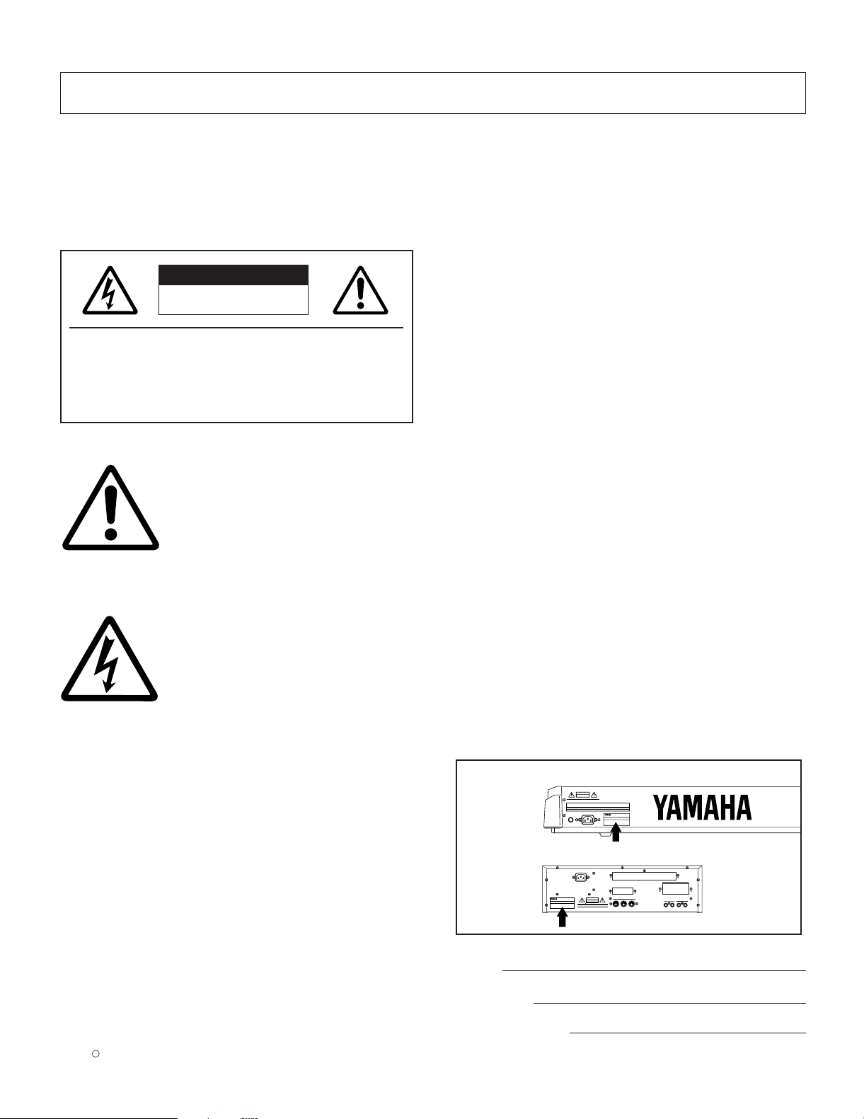
NAME PLATE LOCATION: The graphic below indicates the
location of the name plate. The model number, serial number,
power requirements, etc., are located on this plate. You should
record the model number, serial number, and the date of
purchase in the spaces provided below and retain this manual
as a permanent record of your purchase.
EX5/EX7
CAUTION
EX5R
CAUTION
SPECIFICATIONS SUBJECT TO CHANGE: The information
contained in this manual is believed to be correct at the time
of printing. However, Yamaha reserves the right to change or
modify any of the specifications without notice or obligation to
update existing units.
92-469- 1
Model
Serial No.
Purchase Date
Page 3

IMPORTANT SAFETY INSTRUCTIONS
INFORMATION RELATING TO PERSONAL INJURY, ELECTRICAL SHOCK,
AND FIRE HAZARD POSSIBILITIES HAS BEEN INCLUDED IN THIS LIST.
WARNING- When using any electrical or electronic product,
basic precautions should always be followed. These
precautions include, but are not limited to, the following:
1. Read all Safety Instructions, Installation Instructions,
Special Message Section items, and any Assembly
Instructions found in this manual BEFORE making any
connections, including connection to the main supply.
2. Do not attempt to service this product beyond that
described in the user-maintenance instructions. All other
servicing should be referred to qualified service personnel.
3. Main Power Supply Verification: Yamaha products are
manufactured specifically for the supply voltage in the area
where they are to be sold. If you should move, or if any doubt
exists about the supply voltage in your area, please contact
your dealer for supply voltage verification and (if applicable)
instructions. The required supply voltage is printed on the
name plate. For name plate location, please refer to the
graphic found in the Special Message Section of this manual.
8. This product was NOT designed for use in wet/damp
locations and should not be used near water or exposed to
rain. Examples of wet /damp locations are; near a swimming
pool, spa, tub, sink, or wet basement.
9. This product should be used only with the components
supplied or; a cart ,rack, or stand that is recommended by the
manufacturer. If a cart, rack, or stand is used, please observe
all safety markings and instructions that accompany the
accessory product.
10. The power supply cord (plug) should be disconnected
from the outlet when electronic products are to be left unused
for extended periods of time. Cords should also be
disconnected when there is a high probability of lightening
and/or electrical storm activity.
11. Care should be taken that objects do not fall and
liquids are not spilled into the enclosure through any openings
that may exist.
4. DANGER-Grounding Instructions: This product must be
grounded and therefore has been equipped with a three pin
attachment plug. If this product should malfunction, the ground
pin provides a path of low resistance for electrical current,
reducing the risk of electrical shock. If your wall socket will not
accommodate this type plug, contact an electrician to have
the outlet replaced in accordance with local electrical codes.
Do NOT modify the plug or change the plug to a different type!
5. WARNING: Do not place this product or any other
objects on the power cord or place it in a position where
anyone could walk on, trip over, or roll anything over power or
connecting cords of any kind. The use of an extension cord is
not recommended! If you must use an extension cord, the
minimum wire size for a 25' cord (or less) is 18 AWG. NOTE:
The smaller the AWG number, the larger the current handling
capacity. For longer extension cords, consult a local
electrician.
6. Ventilation: Electronic products, unless specifically
designed for enclosed installations, should be placed in
locations that do not interfere with proper ventilation. If
instructions for enclosed installations are not provided, it must
be assumed that unobstructed ventilation is required.
7. Temperature considerations: Electronic products should
be installed in locations that do not seriously contribute to their
operating temperature. Placement of this product close to heat
sources such as; radiators, heat registers etc., should be
avoided.
12. Electrical/electronic products should be serviced by a
qualified service person when:
a. The power supply cord has been damaged; or
b. Objects have fallen, been inserted, or liquids have
been spilled into the enclosure through openings; or
c. The product has been exposed to rain; or
d. The product does not operate, exhibits a marked
change in performance; or
e. The product has been dropped, or the enclosure of the
product has been damaged.
13. This product, either alone or in combination with an
amplifier and headphones or speaker/s, may be capable of
producing sound levels that could cause permanent hearing
loss. DO NOT operate for a long period of time at a high
volume level or at a level that is uncomfortable. If you
experience any hearing loss or ringing in the ears, you should
consult an audiologist.
IMPORTANT: The louder the sound, the shorter the time
period before damage occurs.
14. Some Yamaha products may have benches and/or
accessory mounting fixtures that are either supplied as a part
of the product or as optional accessories. Some of these items
are designed to be dealer assembled or installed. Please
make sure that benches are stable and any optional fixtures
(where applicable) are well secured BEFORE using. Benches
supplied by Yamaha are designed for seating only. No other
uses are recommended.
92-469- 3
PLEASE KEEP THIS MANUAL
Page 4

FCC INFORMATION (U.S.A.)
1. IMPORTANT NOTICE: DO NOT MODIFY THIS UNIT!
This product, when installed as indicated in the instructions
contained in this manual, meets FCC requirements. Modifications
not expressly approved by Y amaha may void your authority, granted
by the FCC, to use the product.
2. IMPORTANT: When connecting this product to accessories and/or
another product use only high quality shielded cables. Cable/s
supplied with this product MUST be used. Follow all installation
instructions. Failure to follow instructions could void your FCC
authorization to use this product in the USA.
3. NOTE: This product has been tested and found to comply with the
requirements listed in FCC Regulations, Part 15 for Class “B” digital
devices. Compliance with these requirements provides a
reasonable level of assurance that your use of this product in a
residential environment will not result in harmful interference with
other electronic devices. This equipment generates/uses radio
frequencies and, if not installed and used according to the
instructions found in the users manual, may cause interference
harmful to the operation of other electronic devices. Compliance
with FCC regulations does not guarantee that interference will not
* This applies only to products distributed by YAMAHA CORPORATION OF AMERICA.
ADVARSEL!
Lithiumbatteri—Eksplosionsfare ved fejlagtig håndtering. Udskiftning
må kun ske med batteri af samme fabrikat og type. Levér det brugte
batteri tilbage til leverandoren.
VARNING
Explosionsfara vid felaktigt batteribyte. Använd samma batterityp
eller en ekvivalent typ som rekommenderas av apparattillverkaren.
Kassera använt batteri enlight fabrikantens instruktion.
VAROITUS
Paristo voi räjähtää, jos se on virheellisesti asennettu. Vaihda paristo
ainoastaan laitevalmistajan suosittelemaan tyyppiin. Hävitä käytetty
paristo valmistajan ohjeiden mukaisesti.
NEDERLAND
NETHERLAND
• Dit apparaat bevat een lithium batterij voor geheugen back-up.
• This apparatus contains a lithium battery for memory back-up.
occur in all installations. If this product is found to be the source of
interference, which can be determined by turning the unit “OFF”
and “ON”, please try to eliminate the problem by using one of the
following measures:
Relocate either this product or the device that is being affected by
the interference.
Utilize power outlets that are on different branch (circuit breaker or
fuse) circuits or install AC line filter/s.
In the case of radio or TV interference, relocate/reorient the
antenna. If the antenna lead-in is 300 ohm ribbon lead, change the
lead-in to co-axial type cable.
If these corrective measures do not produce satisfactory results,
please contact the local retailer authorized to distribute this type of
product. If you can not locate the appropriate retailer, please contact
Yamaha Corporation of America, Electronic Service Division, 6600
Orangethorpe Ave, Buena Park, CA90620
The above statements apply ONLYto those products distributed by
Yamaha Corporation of America or its subsidiaries.
WARNING: THIS APPARATUS MUST BE EARTHED
IMPORTANT. The wires in this mains lead are coloured in
accordance with the following code:
As the colours of the wires in the mains lead of this apparatus
may not correspond with the coloured markings identifying the
terminals in your plug proceed as follows:
The wire which is coloured GREEN-and-YELLOW must be
connected to the terminal in the plug which is marked by the
letter E or by the safety earth symbol or colored GREEN or
GREEN-and-YELLOW.
The wire which is coloured BLUE must be connected to the
terminal which is marked with the letter N or coloured BLACK.
The wire which is coloured BROWN must be connected to the
terminal which is marked with the letter L or coloured RED.
IMPORTANT NOTICE FOR THE UNITED
KINGDOM
Connecting the Plug and Cord
GREEN-AND-YELLOW: EARTH
BLUE : NEUTRAL
BROWN : LIVE
• Raadpleeg uw leverancier over de verwijdering van de batterij op
het moment dat u het apparaat ann het einde van de levensduur
afdankt of de volgende Yamaha Service Afdeiing:
Yamaha Music Nederland Service Afdeiing
Kanaalweg 18-G, 3526 KL UTRECHT
Tel. 030-2828425
• For the removal of the battery at the moment of the disposal at the
end of the service life please consult your retailer or Yamaha
Service Center as follows:
Yamaha Music Nederland Service Center
Address : Kanaalweg 18-G, 3526 KL UTRECHT
Tel : 030-2828425
• Gooi de batterij niet weg, maar lever hem in als KCA.
• Do not throw away the battery. Instead, hand it in as small chemical
waste.
• This applies only to products distributed by Yamaha-Kemble Music (U.K.) Ltd.
Page 5
PRECAUTIONS
PLEASE READ CAREFULLY BEFORE PROCEEDING
* Please keep these precautions in a safe place for future reference.
WARNING
Always follow the basic precautions listed below to avoid the possibility of serious injury or even death from electrical shock,
short-circuiting, damages, fire or other hazards. These precautions include, but are not limited to, the following:
• This instrument contains no user-serviceable parts. Do not attempt to
disassemble or modify the internal components in any way.
• Do not expose the instrument to rain, use it near water or in damp or wet
conditions, or place containers on it containing liquids which might spill into
any openings.
• If the power cord or plug becomes frayed or damaged, or if there is a sudden
loss of sound during use of the instrument, or if any unusual smells or smoke
should appear to be caused by it, immediately turn off the power switch,
disconnect the electric plug from the outlet, and have the instrument
inspected by qualified Yamaha service personnel.
• Only use the voltage specified as correct for the instrument. The required
voltage is printed on the name plate of the instrument.
• Always connect the three-pin attachment plug to a properly grounded power
source. (For more information about the main power supply, see page 16.)
• Before cleaning the instrument, always remove the electric plug from the
outlet. Never insert or remove an electric plug with wet hands.
• Check the electric plug periodically and remove any dirt or dust which may
have accumulated on it.
CAUTION
Always follow the basic precautions listed below to avoid the possibility of physical injury to you or others, or damage to the
instrument or other property. These precautions include, but are not limited to, the following:
• Do not place the power cord near heat sources such as heaters or radiators,
and do not excessively bend or otherwise damage the cord, place heavy
objects on it, or place it in a position where anyone could walk on, trip over,
or roll anything over it.
• When removing the electric plug from the instrument or an outlet, always hold
the plug itself and not the cord. Pulling by the cord can damage it.
• Do not connect the instrument to an electrical outlet using a multipleconnector. Doing so can result in lower sound quality, or possibly cause
overheating in the outlet.
• Remove the electric plug from the outlet when the instrument is not to be used
for extended periods of time, or during electrical storms.
• Before connecting the instrument to other electronic components, turn off the
power for all components. Before turning the power on or off for all
components, set all volume levels to minimum.
• Do not expose the instrument to excessive dust or vibrations, or extreme cold
or heat (such as in direct sunlight, near a heater, or in a car during the day) to
prevent the possibility of panel disfiguration or damage to the internal
components.
• Do not use the instrument near other electrical products such as televisions,
radios, or speakers, since this might cause interference which can affect
proper operation of the other products.
• Do not place the instrument in an unstable position where it might
accidentally fall over.
• Before moving the instrument, remove all connected cables.
• When cleaning the instrument, use a soft, dry cloth. Do not use paint
thinners, solvents, cleaning fluids, or chemical-impregnated wiping cloths.
Also, do not place vinyl, plastic or rubber objects on the instrument, since
this might discolor the panel or keyboard.
• Do not rest your weight on, or place heavy objects on the instrument, and do
not use excessive force on the buttons, switches or connectors.
• Use only the stand/rack specified for the instrument. When attaching the stand
or rack, use the provided screws only. Failure to do so could cause damage to
the internal components or result in the instrument falling over.
• Do not operate the instrument for a long period of time at a high or
uncomfortable volume level, since this can cause permanent hearing loss. If
you experience any hearing loss or ringing in the ears, consult a physician.
■ REPLACING THE BACKUP BATTERY
• This instrument contains a non rechargeable internal backup battery which
permits internal data to remain stored even when the power is off. When the
backup battery needs replacing, the message "Change internal battery!" will
display in the LCD. When this happens, immediately back up your data, then
have qualified Yamaha service personnel replace the backup battery.
• Do not attempt to replace the backup battery yourself, in order to prevent the
possible serious hazards. Always have qualified Yamaha service personnel
replace the backup battery.
• Never place the backup battery in a location that a child can reach, since a
child might accidentally swallow the battery. If this should happen, consult a
physician immediately.
■ SAVING USER DATA
• Always save data to a floppy disk frequently, in order to help prevent the loss
of important data due to a malfunction or user operating error.
Yamaha cannot be held responsible for damage caused by improper use or
modifications to the instrument, or data that is lost or destroyed.
Always turn the power off when the instrument is not in use.
(2)AC-2
Page 6
The Yamaha EX5 and EX7 Music Synthesizers, and the EX5R Tone Generator, offer more
music performance and production power than ever before available in a single keyboard or
tone generator unit. All three models feature a unique Extended Synthesis system which
incorporates a number of the most advanced tone generator technologies currently available
… plus a full-featured sampling system. There’s also a top-quality internal effect system so
no extra sound-processing equipment is required. 16-track song and 8-track pattern
sequencers provide sophisticated on-board sequence programming and editing capability,
while a unique 4-track arpeggiator function adds extended performance and
accompaniment capability. The EX-series keyboards and tone generator also offer one of the
most versatile and intuitive real-time control systems available, and they’re expandable to
suit a wide range of professional systems and requirements.
We urge you to read through at least the introductory section of this owner’s manual while
familiarizing yourself wit your EX5, EX5R, or EX7, and keep th manual in a safe place for
future reference.
About the Manual
This owner’s manual is divided into two main sections: The Introductory Section, and the Reference
Section:
■Introductory Section
This section has been designed to provide you with an overall understanding of the EX5, EX5R, and EX7, as
well as some hints as how to use these advanced instruments most effectively. It will also refer you to
corresponding sections in the Reference section, so you can refer to the pertinent details as necessary. Use the
Introductory Section as a guide and directory to the main features and functions of the EX5, EX5R, and EX7.
■Reference Section
The Reference Section contains full details and instructions for all of the EX features and functions. You
should be able to find the information you need via the table of contents, the index at the back of the manual,
or via the Introductory Section, described above.
(EX5/5R)
Products bearing the SONDIUS-XG logo are licensed under patents of Stanford University and Yamaha as listed
on the internet web site, <http://www.sondius-xg.com>.
This product is not compatible with the XG format or XG song data.
Included Accessories
Demonstration Disk 1-4
Owner’s Manual
Data List
AC Power Cord
Copying of the commercially available music sequence data and/or digital audio files is strictry prohibited except for your
personal use.
The illustrations and LCD screens as shown in this owner’s manual are for instructional purposes only, and may appear
somewhat different from those on your instrument.
The company names and product names in this Owner’s Manual are the trademarks or registered trademarks of their
respective companies.
6
Page 7

Contents
Introductory
Section
Reference
Section
Voice Mode
Performance
Mode
Sample Mode
Song Mode
Pattern Mode
Arpeggio
Mode
Disk Mode
Utility Mode
Appendix
Introductory Section
The Controls & Connectors ................................8
Setting Up ........................................................16
The Supplied Disks, Demos, & Factory Set Data
EX System Overview........................................28
Extended Synthesis ..........................................29
AWM Synthesis ....................................................29
Virtual Acoustic Synthesis (EX5/5R) ................30
AN Synthesis (Analog Physical Modeling)
FDSP Synthesis
(Formulated Digital Signal Processing) ..............34
Voice and Performance Selection......................36
Voice Structure & Editing Hints ......................40
System Overview..................................................40
Polyphony..............................................................45
Editing Control ....................................................45
Voice Store Procedure ..........................................48
The Power of the Performance Mode ..............49
Performance Store Procedure ..............................53
Performance Mode DSP Limitations ..................54
The Controllers ................................................55
The EX Controllers ..............................................55
Scene Switching & Morphing..............................57
Controller Sets ......................................................58
Sequencer Functions ........................................60
Sequencer Record Modes & Editing....................62
Play Effects & Groove Quantization ..................64
The EX Effect System ......................................65
Sampling ..........................................................69
The Key Map Mode ..........................................72
....25
............33
Reference Section
Voice Mode........................................................75
Voice Play Mode....................................................75
Voice Edit Mode....................................................76
Voice Job Mode ..................................................148
Wave Edit Mode..................................................150
Wave Job Mode ..................................................154
Performance Mode..........................................156
Performance Play Mode ....................................156
Performance Edit Mode ....................................158
Performance Job Mode ......................................172
Sample Mode ..................................................175
Sample Play Mode ..............................................175
Sample Record Mode..........................................176
Sample Edit Mode ..............................................179
Sample Job Mode ................................................182
Song Mode ......................................................185
Song Play Mode ..................................................185
Song Record Mode..............................................193
Song Edit Mode ..................................................201
Song Job Mode....................................................206
Pattern Mode ..................................................219
Pattern Play Mode ..............................................219
Pattern Record Mode..........................................223
Pattern Edit Mode ..............................................226
Pattern Job Mode................................................227
Arpeggio Mode................................................238
Arpeggio Record Mode ......................................245
Arpeggio Edit Mode ..........................................247
Arpeggio Job Mode ............................................249
Disk Mode ......................................................259
Utility Mode....................................................270
Appendix ........................................................278
Optional Boards/Memories................................278
Troubleshooting..................................................291
LCD Messages ....................................................294
Specifications ......................................................295
Index....................................................................296
7
Page 8
SCENE
2
1
OCTAVE
DOWN UP
PITCH MODULATION1 MODULATION 2
A D GAIN
VOLUME
MODE
EX5/7
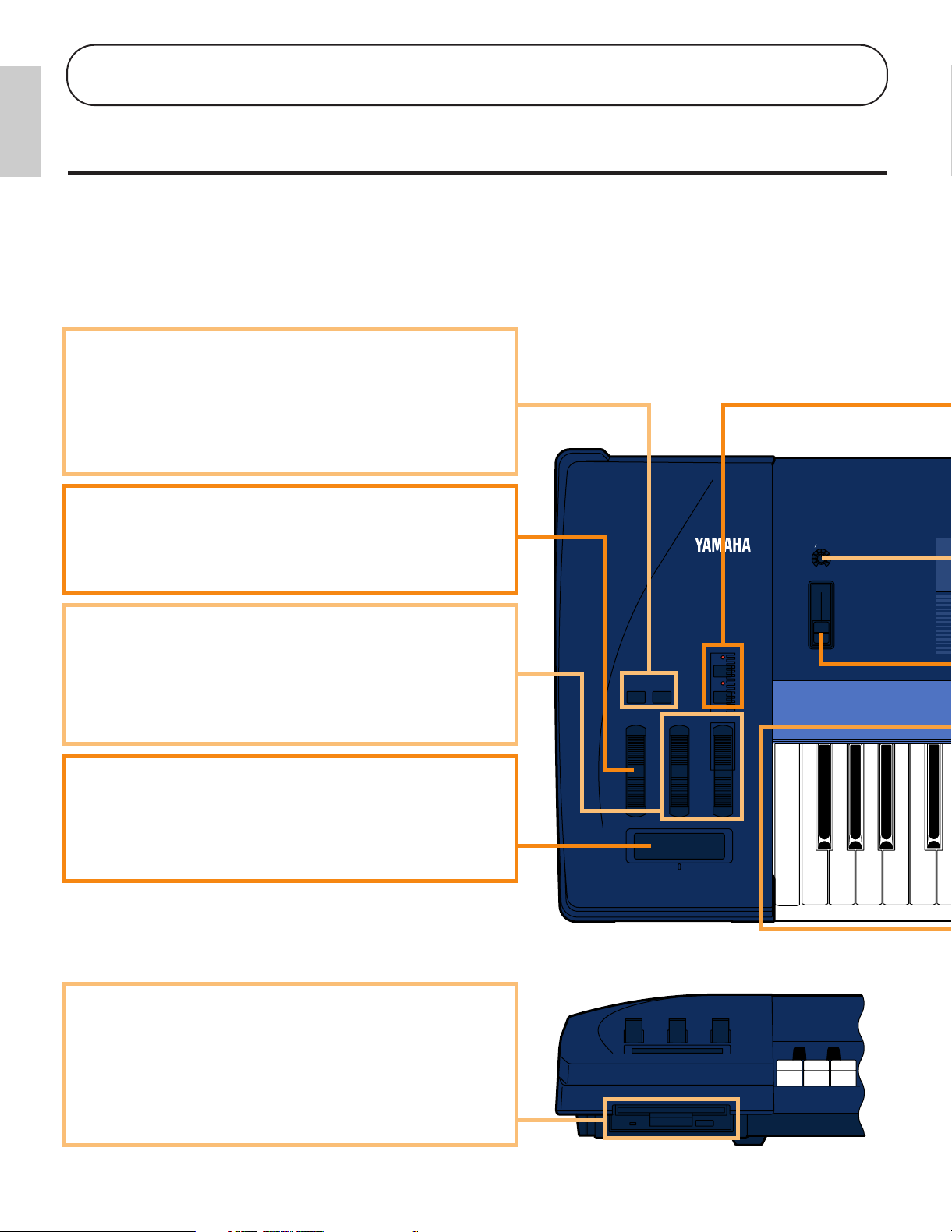
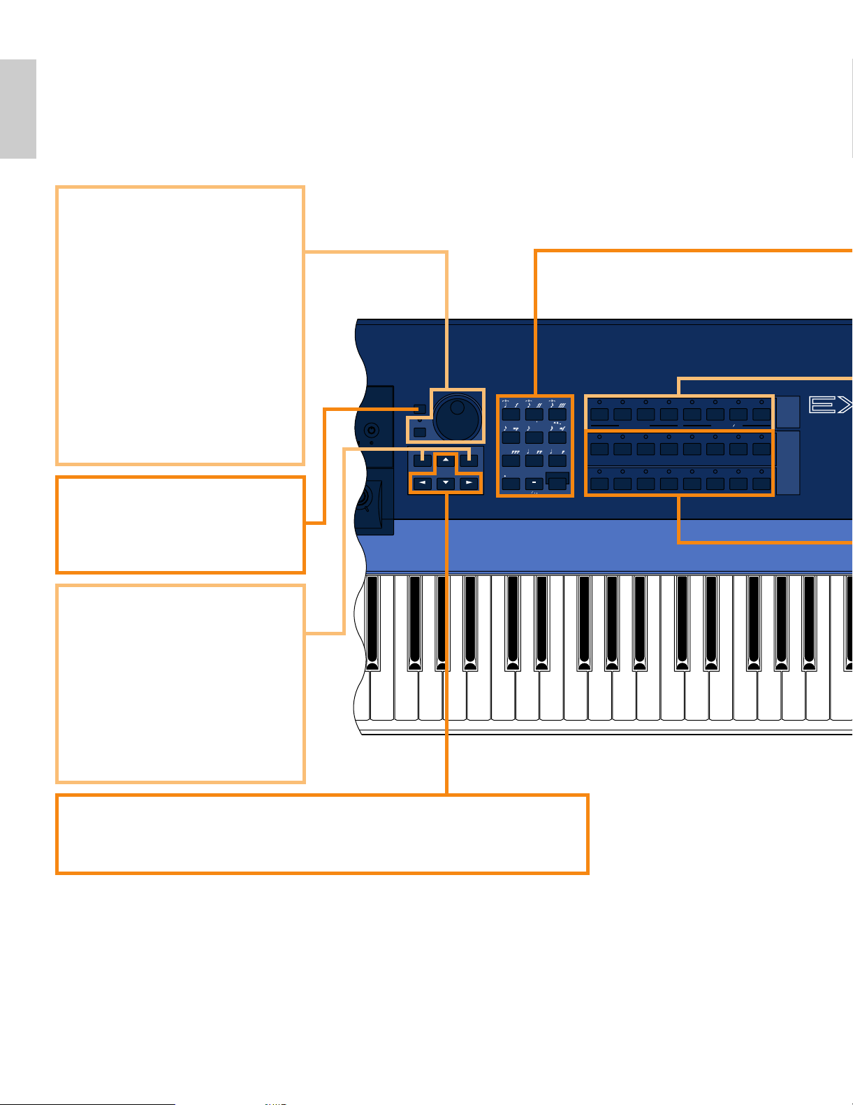
1 OCTAVE [DOWN] and [UP] Keys (EX5 and EX7 only)
Shift the pitch of the keyboard up or down up to five octaves in
one-octave steps. The pitch is shifted one octave in the
corresponding direction, up to the maximum, each time one of
these keys is pressed. When the current octave is higher than
the normal octave the UP indicator will be lit, and vice versa.
Neither indicator will be lit when the normal octave is selected.
2 [PITCH] Wheel (EX5 and EX7 only)
This self-centering pitch wheel allows smooth upward and
downward pitch bends. A range of other control functions can
be assigned to the PITCH wheel.
➡
See page 55 for more information.
3 [MODULATION 1] and [MODULATION 2] Wheels
(EX5 and EX7 only)
Can be assigned to any of the extensive range of controller
parameters for extraordinary expressive control. The
MODULATION 2 wheel can also be used for “scene
morphing” — i.e. smoothly changing from one memorized
scene to the other.
➡
See page 55 for more information.
4 Ribbon Controller (EX5 and EX7 only)
Another expressive EX controller, the Ribbon Controller is
touch sensitive, and is controlled by running a finger lightly
across its surface to the left or right. The Ribbon Controller can
be assigned to the full range of EX parameters.
➡
See page 56 for more information.
9 Floppy Disk Drive
The built-in floppy disk drive allows easy, economical, highvolume storage of voice data. The disk-in-use LED indicator
below the drive slot lights while any disk operation is in
progress (NEVER attempt to remove a disk or turn the power
off while a disk operation is in progress). The eject key, also
below the disk slot, is used to remove disks from the drive.
➡
See page 259 for more information.
Introductory
Section
Introductory Section
The Controls & Connectors
The following brief descriptions of the EX controls and connectors should help you to understand the
overall logic of the interface.
Front Panel
8
Page 9
Introductory
Section
123456
POWER
EXIT
SHIFT
TONE GENERATOR
REALTIME CONTROL
EXTENDED SYNTHESIS
1 2 3 4 5 6
VOICE PERFORM SONG PATTERN SAMPLE
JOB
LMONO R
BREATH PHONES
VOLUME
AD
INPUT
A D GAIN
STORE UTILITY
DISK
SC2
SC1
EDIT
COMPARE
KEYMAP BYPASS
ARPEG KNOB
CANCEL
CURSOR
DATA
TOP
REC STOP PLAY
POWER
REW FWD
ON OFF
DEC NO INC YES
SPACE
ABC
0
123
456
789
ENTER
DEF GHI JKL
MNO
PQR
STU
VWX YZ
F1 F2 F3 F4 F5 F6 F7 F8 EXIT
SHIFT
VOICE
PERFORMANCE
SONG
PATTERN SAMPLE
EDIT
JOB STORE UTILITY DISK
FWDREWTOP
KNOB MODE
ARPEGGIO
COMPARE
KEYMAP EF BYPASS REC STOP PLAY
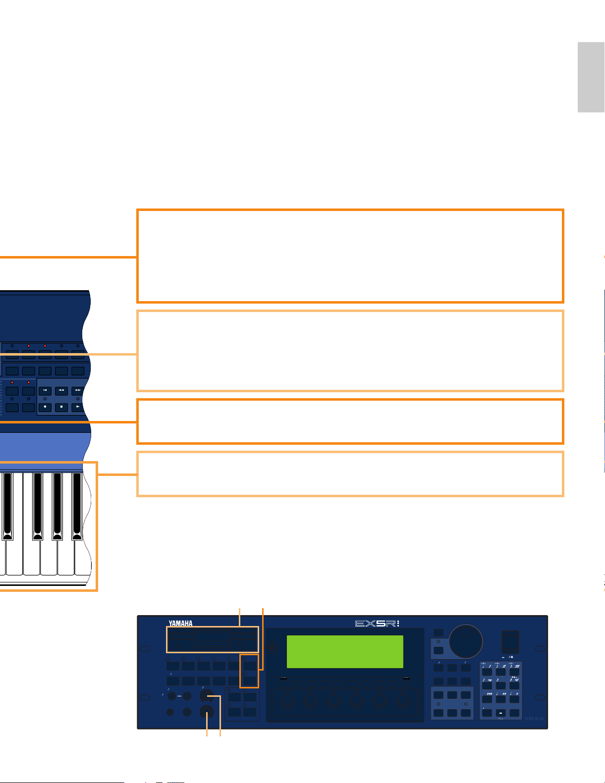
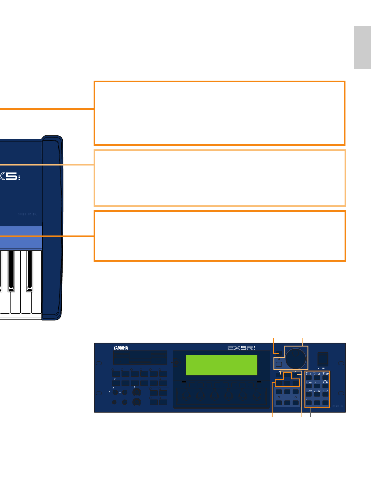
8 Keyboard (EX5 and EX7 only)
The EX5 has a 76-key keyboard while the EX7 has a 61-key keyboard. Both are velocity and
after-touch sensitive for broad, intimate expressive control.
6 A/D Gain Control
Adjusts the input level of the INPUT R and L/MONO jacks (the INPUT jack on the EX7), and
therefore the level of the signal appearing at the input of the A/D (Analog-to-Digital) converter.
This control is important for setting optimum record level when recording samples in the
SAMPLE mode.
➡
See page 70 for more information.
5 SCENE [1] and [2] Keys ([SC1] and [SC2] on the EX5R)
The SCENE [1] and [2] keys can be used to memorize and recall different settings of the
Controller Knobs, so a complete set of knob settings can be recalled instantaneously. Knob
scenes are stored by using the SCENE keys in conjunction with the STORE key (page 57).
When both SCENE indicators are lit (this is done by pressing one SCENE key while holding the
other), the MODULATION 2 wheel or a foot controller can be used to “morph” between the
two scenes stored in the SCENE [1] and [2] keys (page 57).
7 VOLUME Control
Adjusts the volume of the sound delivered via the rear-panel OUTPUT L/MONO and R jacks
as well as the PHONES jack.
EX5R
76
9 5
* 1, 2, 3, 4 and 8 are not available on EX5R.
9
Page 10
Introductory
Section
MODE
VOICE
PERFORMANCE
SONG
PATTERN SAMPLE
EDIT
JOB STORE UTILITY DISK
FWDREWTOP
KNOB MODE
ARPEGGIO
COMPARE
KEYMAP EF BYPASS REC STOP PLAY
F1 F2 F3 F4 F5 F6 F7 F8
1 2 3 4 5 6
CANCEL
CURSOR
DATA
DEC NO
INC
YES
EXIT
SHIFT
EX5/7
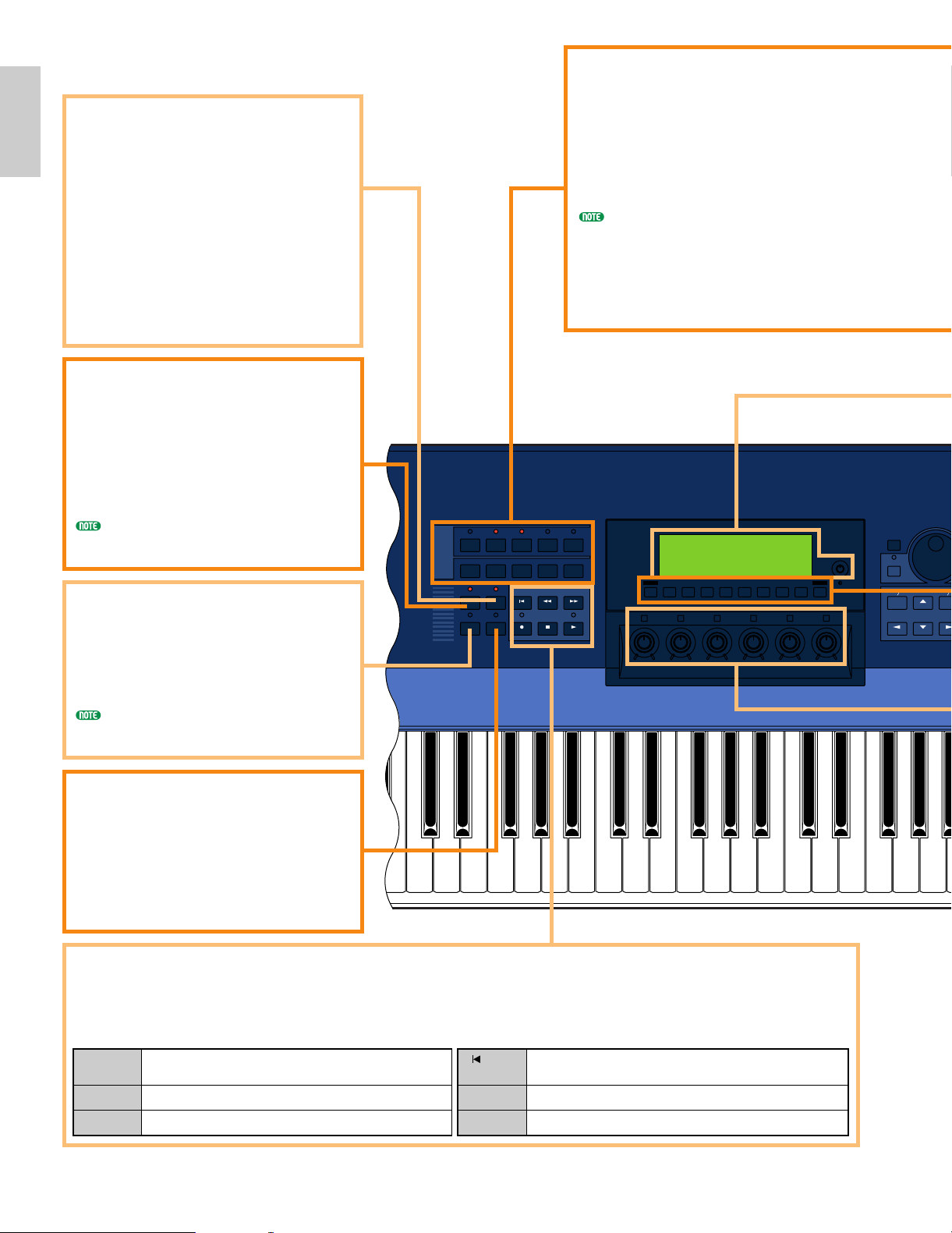
% MODE Keys
The MODE keys select the corresponding
EX modes, or appropriate sub-modes. The
upper row of MODE keys engage the
primary modes, and have LED indicators
to show which mode(s) are currently
active. The lower row of MODE keys
select secondary or utility modes.
You can not enter Pattern mode when
[ARPEGGIO] key or [KEYMAP] key is turned on.
! [ARPEGGIO] Key
([ARPEG] on the EX5R)
This key turns the advanced automatic
arpeggiator on or off. When the
arpeggiator is turned on, the Voice or
Performance Edit mode Arpeggiator edit
display will appear.
➡
See page 238 for more information.
[ARPEGGIO] key functions (can be turned on or
off) when in Voice mode, Performance mode and
Song Play mode.
@ [KEY MAP] Key
Engages the Key Map mode in which
samples, entire patterns, or pattern
tracks can be individually assigned to
separate keys on the keyboard.
➡
See page 72 for more information.
[KEYMAP] key functions (can be turned on or
off) when in Voice mode, Performance mode
and Song mode.
# [EF BYPASS] Key
([BYPASS] on the EX5R)
Turns the type of effects specified in the
Utility mode Other Setup display on or
off. When engaged (i.e. when the
indicator is lit) the specified effects are
bypassed.
➡
See page 276 for more information.
$ Sequencer Keys
The sequencer keys control recording and playback in the Song, Pattern, and Arpeggio modes, and allow you to
locate a specific measure within a song or pattern. Their layout and functions are similar to the transport controls
on a tape recorder.
) [KNOB MODE] Key
([KNOB] on the EX5R)
The six Controller Knobs, described
below, can function either as sound
controllers or data entry knobs. In the
Song, Pattern, Sample, Edit, Job, Store,
Utility and Disk modes the [KNOB
MODE] key switches between data entry
and sound control, allowing you to try out
the effect of knob-related settings without
having to exit from the Edit mode. The
knobs function only as sound controllers
in the Voice and Performance modes.
[I]
REC
[J]
STOP
[F]
START
[ ]
TOP
[G]
REW
[H]
FWD
Press this key to engage the record ready mode. You have to press the
START key to actually start recording.
Press to stop recording or playback.
Press to start recording or playback.
This key takes you directly to the first measure (the “top”) of the current song
or pattern.
Press briefly to move back one measure, or hold for continuous scrolling.
Press briefly to move forward one measure, or hold for continuous scrolling.
10
Page 11
Introductory
Section
TONE GENERATOR
REALTIME CONTROL
EXTENDED SYNTHESIS
1 2 3 4 5 6
VOICE PERFORM SONG PATTERN SAMPLE
JOB
LMONO R
BREATH PHONES
VOLUME
AD
INPUT
A D GAIN
STORE UTILITY
DISK
SC2
SC1
EDIT
COMPARE
KEYMAP BYPASS
ARPEG KNOB
CANCEL
CURSOR
DATA
TOP
REC STOP PLAY
POWER
REW FWD
ON OFF
DEC NO INC YES
SPACE
ABC
0
123
456
789
ENTER
DEF GHI JKL
MNO
PQR
STU
VWX YZ
F1 F2 F3 F4 F5 F6 F7 F8 EXIT
SHIFT
ABC
0
12
45
7
8
DEF GHI
MNO PQR
VWX YZ
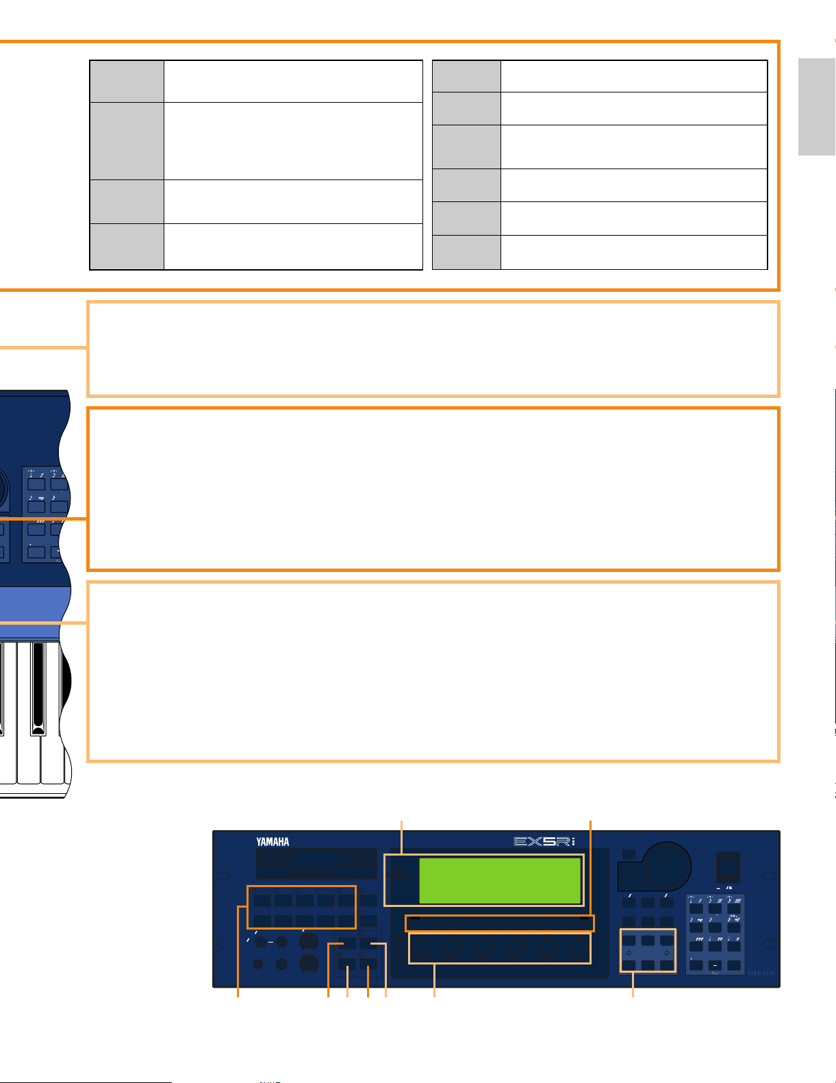
& [F1] through [F8] Function, [SHIFT], and [EXIT] Keys
The functions of these keys depend on the selected mode. They are used to engage a function indicated on the
display immediately above the key or select a page of parameters.
When the “S” symbol appears in the lower left corner of the display, the [SHIFT] key can be used to select a
secondary function menu for the function keys: press the appropriate function key while holding the [SHIFT]
key to access a secondary function.
The [EXIT] key will return you to the next highest level in the display hierarchy when in an editing, utility, or
disk function display. In most cases you can return directly to the top-level primary mode display by directly
pressing the appropriate MODE key.
^ LCD Display Screen & Contrast Control
This large multi-function liquid crystal display screen shows all parameters and prompts you need to operate the
EX5, EX5R, or EX7 with optimum ease and efficiency.
Use the contrast control to achieve the best display visibility (LCD visibility varies greatly with viewing angle and
lighting).
* Controller Knobs
These knobs form an important part of the advanced EX user interface. They can can be assigned to control an
impressively wide range of sound parameters in real time during performance/playback, and they can function as
data entry controls in the editing, utility, disk, and some other modes. The [KNOB MODE] key, described above,
determines which function the knobs assume in the appropriate modes.
Normally when you rotate a controller knob being used for data entry, the corresponding value changes in
relative fashion — i.e. the knob increases or decreases the value of the parameter in relation to the value that was
initially on the display. If you rotate a controller knob while holding the [KNOB MODE] key, however, the
relationship between the controller position and the data value becomes absolute, and the central detented
position of the knob will correspond to the exact center of the parameter range.
The Voice mode lets you select, play, and edit individual voices.
The [VOICE] key indicator also blinks to indicate that a MIDI System
Exclusive message is being received. [→ page 75]
In the Performance mode you can select, play, and edit individual
“performance” programs including multiple layered or split voices and effects.
Press the [VOICE] key while holding the [PERFORMANCE] key to go
directly to the Voice Edit mode from the Performance mode.
The [PERFORMANCE] key indicator also blinks to indicate that a MIDI
System Exclusive message is being received. [→ page 156]
The Song mode provides access to the sophisticated sequence recording,
playback, and editing capabilities provided by the EX5, EX5R, and EX7.
[→ page 185]
Sequence “patterns” which can be used individually or incorporated into
complete songs in the Song mode can be recorded, played, and edited in
the Pattern mode. [→ page 219]
Advanced sample recording and editing features are available via the Sample
mode. [→ page 175]
The [EDIT] key accesses the appropriate editing functions for the currently
selected mode: Voice, Performance, Song, Pattern, or Sample.
Each of the primary modes — Voice, Performance, Song, Pattern, and
Sample — have a range of “jobs” which can be accessed by pressing the
[JOB] key.
This key is used to store edited data to an internal memory location, or
controller knob settings to either of the SCENE keys. [→ pages, 48, 53 and 57]
The UTILITY mode includes MIDI, system and other functions that are
essential for general operation. [→ page 270]
The Disk mode includes disk save and load functions as well as all other
functions you need for efficient data storage and management. [→ page 259]
!@ #) * $
&
%
^
EX5R
[VOICE]
[PERFORMANCE]
[SONG]
[PATTERN]
[SAMPLE]
[EDIT]
[JOB]
[STORE]
[UTILITY]
[DISK]
11
Page 12
Introductory
Section
CURSOR
DATA
DEC NO
INC
YES
BANK
PROGRAM
PART
TRACK
ELEMENT SELECT ELEMENT ONOFF
COMMON OSC PITCH FILTER AMPLITUDE LFO CONTROL EFFECT
ABCDEFGH
12345678
12341234
910111213141516
SPACE
ABC
0
123
456
7
89
ENTER
DEF GHI JKL
MNO PQR
STU
VWX YZ
CANCEL
6
ELEMENT SELECT ELEMENT ONOFF
COMMON OSC PITCH FILTER AMPLITUDE LFO CONTROL EFFECT
ABCDEFGH
12345678
12341234
910111213141516
XIT
0
123
456
789
EX5/7
¡ [DEC/NO] and [INC/YES] Keys
Used to select voices and edit
parameter values in any of the EX
edit modes. Either key can be pressed
briefly for single stepping in the
specified direction, or held for
continuous scrolling. These keys are
also used to respond “Yes” or “No”
to confirmation prompts when
executing certain operations or
saving/loading data.
º [CANCEL] Key
The [CANCEL] key can be used to
cancel an entered value and return to
the previous value if pressed before a
different parameter is selected.
( Data Dial and
[CURSOR/DATA] Key
The Data Dial provides a fast, efficient way to
cover a broad range of voice numbers when,
for example, you’re looking for a voice but
don’t know the number. It's also handy for
making large value changes in any of the
editing and utility modes.
When editing the Data Dial will normally
increment or decrement the selected
parameter value. When the [CURSOR/DATA]
key is pressed and its indicator is lit, however,
the Data Dial moves the cursor around the
display rather than changing values. This can
be handy when navigating a complex display
which includes many individual parameters.
™ Cursor Keys
These 4 keys move the "cursor" around the display screen, highlighting the various
items that are available for selection or parameters that are available for editing (the
cursor appears as a dark block with inverse characters).
12
Page 13
Introductory
Section
TONE GENERATOR
REALTIME CONTROL
EXTENDED SYNTHESIS
1 2 3 4 5 6
VOICE PERFORM SONG PATTERN SAMPLE
JOB
LMONO R
BREATH PHONES
VOLUME
AD
INPUT
A D GAIN
STORE UTILITY
DISK
SC2
SC1
EDIT
COMPARE
KEYMAP BYPASS
ARPEG KNOB
CANCEL
CURSOR
DATA
TOP
REC STOP PLAY
POWER
REW FWD
ON OFF
DEC NO INC YES
SPACE
ABC
0
123
456
789
ENTER
DEF GHI JKL
MNO
PQR
STU
VWX YZ
F1 F2 F3 F4 F5 F6 F7 F8 EXIT
SHIFT
MUSIC SYNTHESIZER
REALTIME CONTROL
EXTENDED SYNTHESIS
£ Numeric Keypad and [ENTER] Key
These keys allow direct entry of numeric values where applicable. Enter the required value
via the numeric keys — the entered number will flash on the displays — then press the
[ENTER] key to actually enter the specified value. The [ENTER] key is also used to enter
notes and other events when editing sequence data, and to execute a specified job or disk
function. The numeric keys are also used to specify note lengths and dynamics (velocity)
when step recording in the SONG or PATTERN mode.
➡
See page 199 for more information.
¢ Bank [A] Through [H] Keys (EX5 and EX7 only)
Each of the EX5 and EX7 voice memories — P1 (Preset 1), P2 (Preset 2), I1 (Internal 1)
and I2 (Internal 2) — has 128 voice memory locations arranged in 8 banks of 16 voices
each. The 128 performance memories are also organized in 8 banks of 16 performance
setups. These keys select the bank from which an individual voice or performance setup
will be selected. When editing voice parameters they are also used to select and mute
elements.
∞ Program Number [1] Through [16] Keys (EX5 and EX7 only)
The program number keys are used in conjunction with the bank keys to select any of the
128 voice memory locations within the currently selected voice memory — P1 (Preset 1), P2
(Preset 2), I1 (Internal 1) and I2 (Internal 2) — in the VOICE mode, or any of the 128
performance memory locations in the Performance mode. In the Voice Edit mode keys [1]
through [8] can be used to directly select the various edit displays.
™ ¡£
(º
EX5R
* ¢ and ∞ are not available on EX5R.
13
Page 14
Introductory
Section
CAUTION
ATTENTION
WARNING
:RISQUE DE CHOC ELECTRIQUE NE PAS OUVRIR.
TO REDUCE THE RISK OF FIRE OR ELECTRIC
SHOCK,DO NOT EXPOSE THIS PRODUCT TO RAIN OR MOISTURE.
POWER
ON
OFF
AC INLET
INDIVIDUAL OUTPUT
A/D
INPUT
6543
OUTPUT
R L MONO
FOOT
SWITCH
FOOT
CONTROLLER
FOOT
VOLUME
SUSTAIN
DIGITAL OUTPUT WORD CLOCK IN
AES EBU
SCSI
MIDI A
OUTTHRU IN
BREATH PHONES
CAUTION
ATTENTION
WARNING
:RISQUE DE CHOC ELECTRIQUE NE PAS OUVRIR.
TO REDUCE THE RISK OF FIRE OR ELECTRIC
SHOCK,DO NOT EXPOSE THIS PRODUCT TO RAIN OR MOISTURE.
POWER
ON
OFF
AC INLET
EX5
EX7
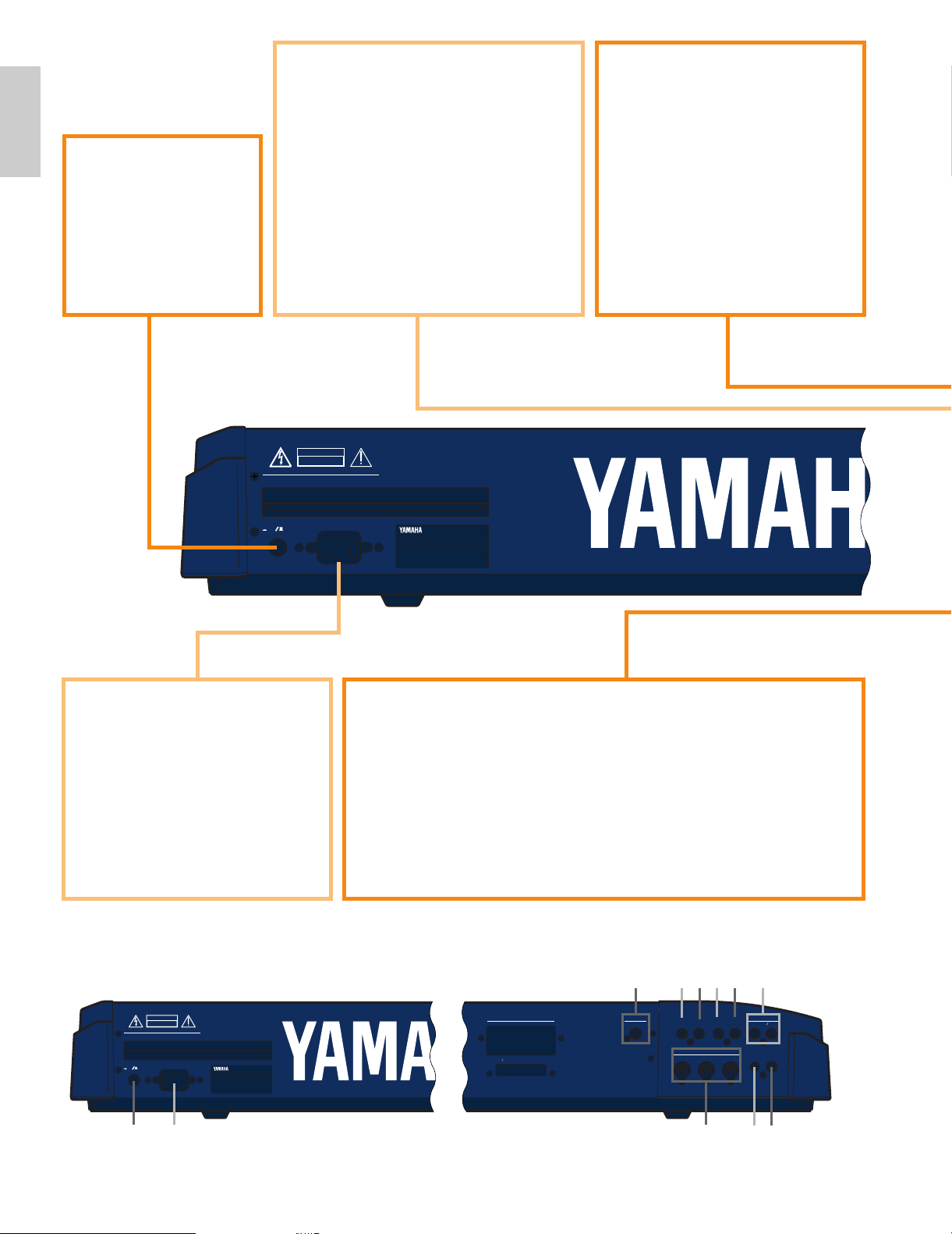
ª A/D INPUT L/MONO and
R Jacks (A/D INPUT on the EX7)
Line and microphone sampling
sources can be connected to these
jacks. Line or microphone input
sensitivity is switched via the
“line/mic” parameter in the Sample
mode REC display (page 176), and
fine input sensitivity adjustment
can be carried out via the A/D
GAIN control on the control panel.
➡
See page 70 for more
information.
• INDIVIDUAL OUTPUT 1 and
2 Jacks (EX5 and EX5R only)
In addition to the stereo OUTPUT
L/MONO and R jacks, the EX5 and EX5R
initially have two individual outputs: the
INDIVIDUAL OUTPUT 1 and 2 jacks.
Individual “parts” of a performance setup
can be assigned to different individual
outputs via the PERFORMANCE EDIT
mode PART display (see page 164). Four
individual outputs can be added to the
EX5, EX5R, and EX7 by installing the
optional EXIDO1 Individual Output
Board (page 19.)
§ [POWER] Switch
Press to turn power ON
or OFF. The EX5 and
EX7 power switch is
located on the rear panel
near the AC power cord
socket. The EX5R power
switch is located on the
front panel.
‚ MIDI IN, OUT and THRU Connectors
The MIDI IN connectors receive data from an external sequencer or
other MIDI device which is to control or transmit data to the EX. The
MIDI THRU connector simply re-transmits the data received at the MIDI
IN connector, allowing convenient chaining of MIDI devices. The MIDI
OUT connectors transmit data corresponding to all EX performance and
playback operations.
The EX5 is equipped with two sets of MIDI terminals: MIDI A and MIDI
B. The MIDI A group includes MIDI IN, OUT, and THRU terminals,
while the MIDI B group only has MIDI IN and OUT terminals.
➡
See page 22 for more information.
¶ AC Power Cord Socket
Be sure the plug the AC power cord
into this socket before plugging the
power cord into an AC outlet.
Use only the AC power cord
supplied with the EX5, EX5R, or
EX7. If the supplied cord is lost or
damaged ands needs to be replaced,
contact your Yamaha dealer. The
use of an inappropriate replacement
can pose a fire and shock hazard!
§ ¶
‚
fifl
›‡‹¤⁄ª
* • is not available on EX7.
Rear Panel
14
Page 15
Introductory
Section
AC INLET
CAUTION
ATTENTION
WARNING
RISQUE DE CHOC ELECTRIQUE NE PAS OUVRIR.
TO REDUCE THE RISK OF FIRE OR ELECTRIC SHOCK,
DO NOT EXPOSE THIS PRODUCT TO RAIN OR MOISTURE.
MIDI
OUTTHRU IN
INDIVIDUAL OUTPUT
65 43
DIGITAL OUTPUT
WORD CLOCK IN
AES EBU
INDIVIDUAL OUTPUT
21
OUTPUT
R
L MONO
VOICE PERFORM SONG PATTERN SAMPLE
JOB
LMONO R
BREATH PHONES
VOLUME
AD
INPUT
A D GAIN
STORE UTILITY
DISK
SC2
SC1
EDIT
COMPARE
KEYMAP BYPASS
ARPEG KNOB
CURSOR
DATA
TOP
REC STOP PLAY
POWER
REW F WD
ON OFF
DEC NO INC YES
SPACE
ABC
0
123
456
789
ENTER
DEF GHI JKL
MNO
PQR
STU
VWX YZ
INDIVIDUAL OUTPUT
INDIVIDUAL OUTPUT
A/D
INPUT
6543 21
R L MONO
OUTPUT
R L MONO
FOOT
SWITCH
FOOT
CONTROLLER
FOOT
VOLUME
SUSTAIN
DIGITAL OUTPUT WORD CLOCK IN
AES EBU
SCSI
MIDI B MIDI A
OUT IN OUTTHRU IN
BREATH PHONES
EX5R
Front
Rear
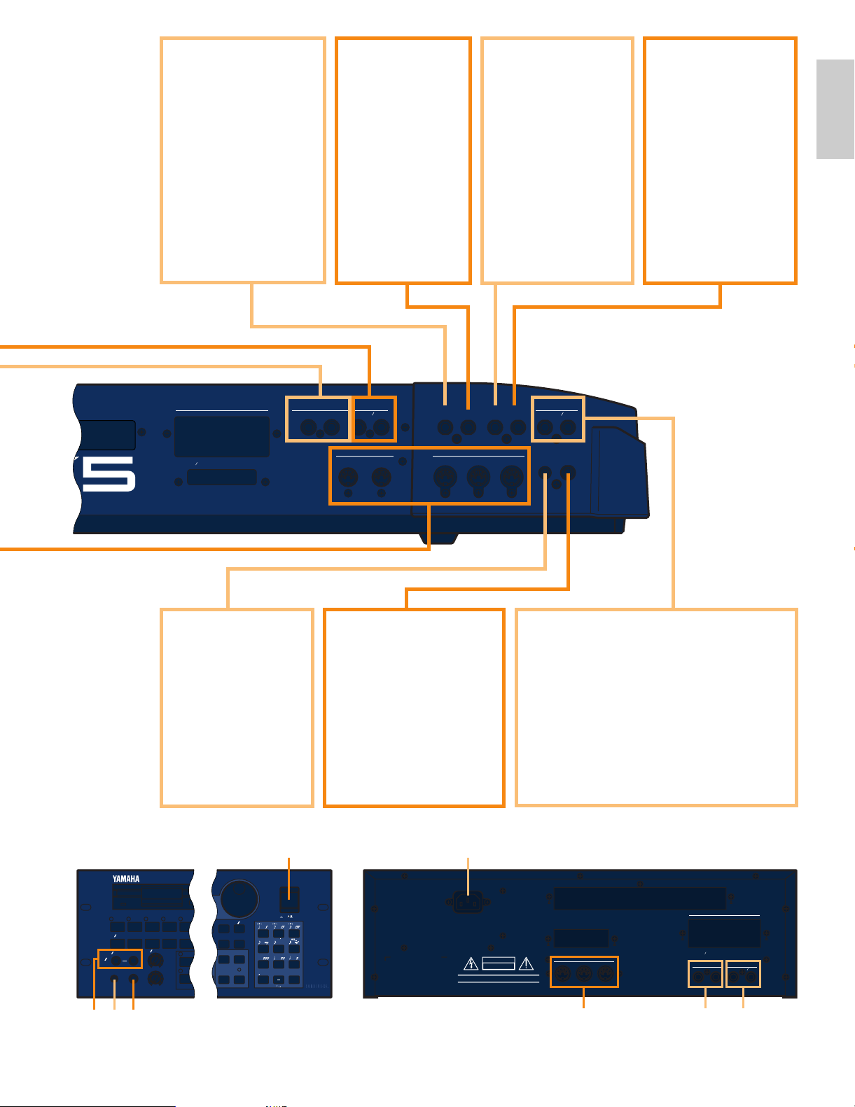
⁄ FOOT SWITCH
Jack
(EX5 and EX7 only)
An optional Yamaha
FC4 or FC5 footswitch
can be connected to
this jack to control of a
range of on/off type
functions: sustain,
sotenuto, portamento,
and others.
➡
See page 17 for more
information.
¤ SUSTAIN Jack
(EX5 and EX7
only)
An optional
Yamaha FC4 or
FC5 footswitch
can be connected
here for sustain
control.
‹ FOOT
CONTROLLER
Jack
(EX5 and EX7 only)
This jack accepts a
Yamaha FC7 Foot
Controller which can
be used to control any
of the EX controller
parameters.
➡
See page 17 for
more information.
› FOOT VOLUME
Jack
(EX5 and EX7 only)
A Yamaha FC7 Foot
Controller can be
plugged in here for
convenient foot
volume or expression
control.
‡ OUTPUT L/MONO and R Jacks
These are the main stereo outputs from
the EX5, EX5R, and EX7. Be sure to
connect both outputs to the appropriate
channels of a stereo sound system in order
to appreciate the full quality of the EX
sound and effects. Connect only the
L/MONO jack when connecting to a mono
sound system.
fl PHONES Jack
Accepts a standard pair of
stereo headphones (1/4"
stereo phone plug) for
headphone monitoring of
the EX sound without the
need for external
amplification equipment.
The EX5R PHONES jack
is on the front panel.
fi
Breath
Controller Jack
Plug an optional
Yamaha BC3 Breath
Controller in here for
expressive breath
control capability.
➡
See page 56 for
more information.
¶
• ‡‚
߻
§
fi
* ⁄, ¤, ‹ and › are not available on EX5R.
15
Page 16
Introductory
Section
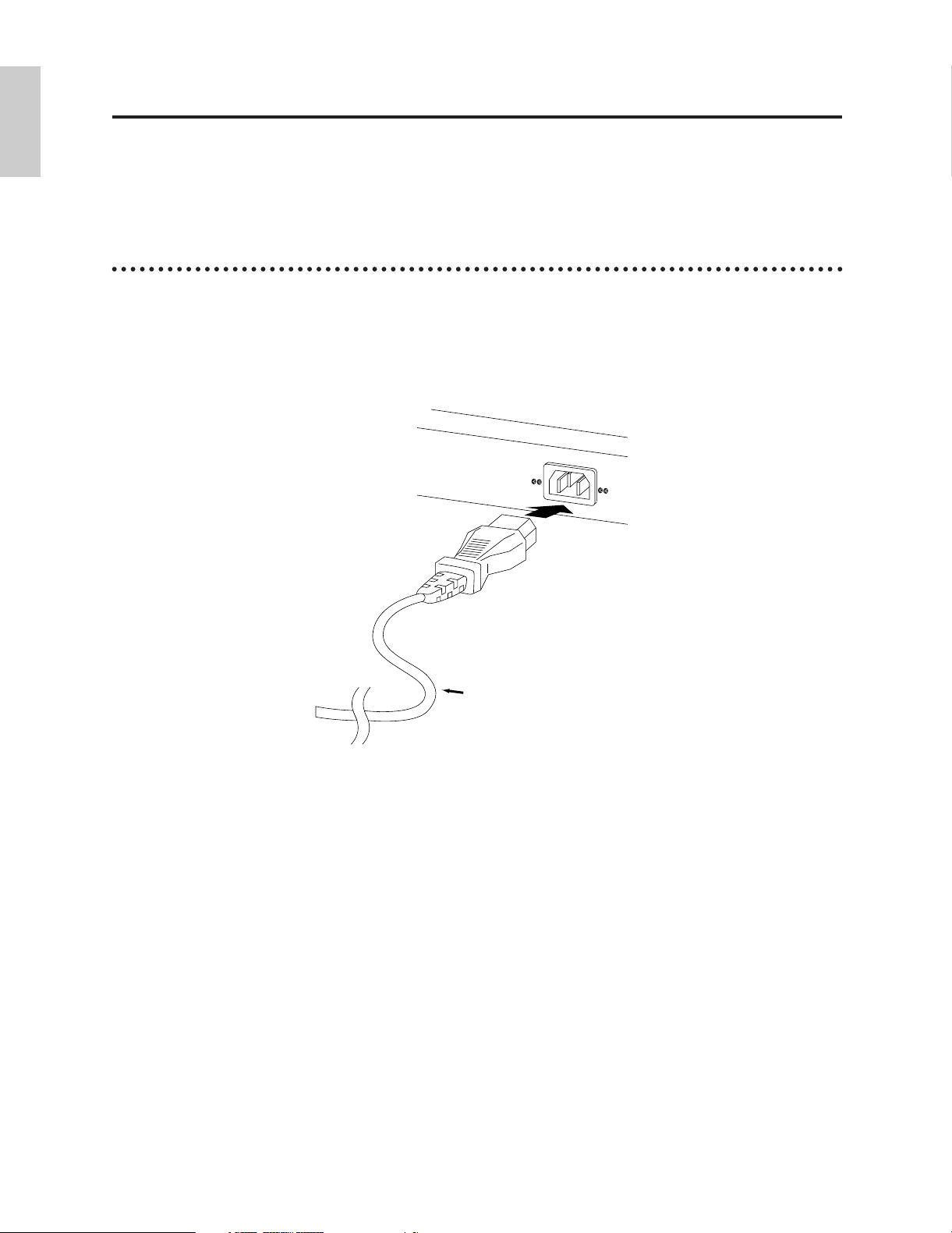
Setting Up
AC Power Cord
EX5/7, EX5R
Rear Panel
The EX5 or EX7 can be used virtually on its own — with a pair of headphones or a simple
instrument amplifier — or it can be the core of complex and powerful music production
system. Naturally, the EX5R Tone Generator will require an external MIDI keyboard or other
controller.
Power Supply
Before making any other connections the “female” end of the AC power cord supplied with the EX5,
EX5R, and EX7 should be firmly plugged into the rear-panel AC cord socket. Ideally the power cord
should then be plugged into a convenient AC outlet after you've made all other necessary connections
and placed the EX5, EX5R, or EX7 in the position in which it will be used. Always make sure that the
POWER switch is in the OFF (extended) position before plugging the power cord in an AC outlet.
WARNING!
Make sure your EX5, EX5R, or EX7 is rated for the AC voltage supplied in the area in which it is to be
used (as listed on the rear panel). Connecting the unit to the wrong AC supply can cause serious damage to
the internal circuitry and may even pose a shock hazard!
Use only the AC power cord supplied with the EX5, EX5R, or EX7. If the supplied cord is lost or damaged
ands needs to be replaced, contact your Yamaha dealer. The use of an inappropriate replacement can pose a
fire and shock hazard!
The type of AC power cord provided with the EX5, EX5R, or EX7 may be different depending on the
country in which it is purchased (a third prong may be provided for grounding purposes). Improper
connection of the grounding conductor can create the risk of electrical shock. Do NOT modify the plug
provided with the EX5/EX5R/EX7. If the plug will not fit the outlet, have a proper outlet installed by a
qualified electrician. Do not use a plug adapter which defeats the grounding conductor.
16
Page 17

External Controllers
Introductory
Section
In addition to the many realtime controllers provided on the EX5 and EX7 panel (the PITCH wheel,
MODULATION 1 wheel, MODULATION 2 wheel and Ribbon Controller), plus the six Controller
Knobs provided on the EX5, EX5R and EX7, a number of additional controllers can be plugged into
the appropriate rear-panel jacks as required.
■ Foot Switches (EX5 and EX7)
At the very least you’ll probably want to plug a footswitch into the SUSTAIN jack for piano-type
sustain control. You might also want to plug a second footswitch into the FOOTSWITCH jack to
control other on/off type functions such as sostenuto, portamento, or arpeggio hold for the
sophisticated automatic arpeggiator feature. Footswitch functions are assigned via the UTILITY
mode, as described on page 275.
■ Foot Controllers (EX5 and EX7)
The EX5 and EX7 have jacks for two optional Yamaha FC7 Foot Controller units: FOOT VOLUME
and FOOT CONTROLLER. An FC7 plugged into the FOOT VOLUME jack can be used (as its
name implies) for main volume or expression control. The desired FOOT VOLUME function can
be selected via the UTILITY mode Controller display, as described on page 275. An FC7 plugged
into the FOOT CONTROLLER jack can be assigned for continuous realtime control of a wide
range of parameters (pages 104 and 163).
For more information on Foot Controller setup and operation, see the instructions packed with the supplied
FC7 Foot Controller.
■ Breath Controller
A Breath Controller can be an essential expressive tool for realistic expression with windinstrument type voices and unprecedented expressive control with other voices. Plug an optional
BC3 Breath Controller into the BREATH jack. The Breath Controller is ideal for controlling
parameters that would normally be affected by a wind player's breath: dynamics, timbre, pitch, and
others.
For more information on Breath Controller setup and operation, see the instructions packed with the optional
BC3 Breath Controller.
17
Page 18
Introductory
Section
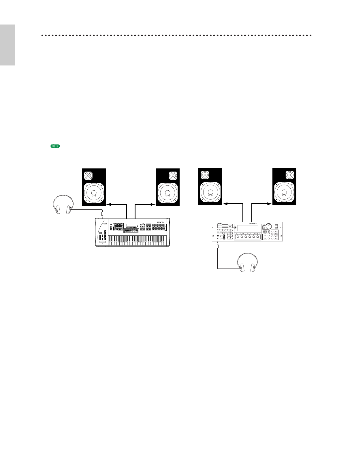
Audio Connections
MUSIC SYNTHESIZER
REALTIME CONTROL
EXTENDED SYNTHESIS
EX5/7
Headphones
EX5R
PHONES
OUTPUT L /
MONO jack
R
Amplified Speaker L Amplified Speaker R
Headphones
PHONES
OUTPUT L /
MONO jack
R
Amplified Speaker L Amplified Speaker R
MUSIC SYNTHESIZER
REALTIME CONTROL
EXTENDED SYNTHESIS
1 2 3 4 5 6
■ Headphones
For private listening and practice headphones are ideal. You don't have to hook up and complete
sound system, and you won't disturb the neighbors no matter how loud or late you play.
Recommended Yamaha headphones for EX monitoring are the HPE-170, HPE-160, or HPE-150
Stereo Headphones. Any standard pair of stereo headphones with a 1/4" stereo phone plug can be
used.
■ Instrument Amplifier or Stereo Sound System
The EX voices and effects are designed to sound their best in stereo, so you should always use a
stereo sound system to appreciate the full impact of the EX voices and expressive features. The
OUTPUT L/MONO and R jacks can be connected directly to musical instrument amplifiers
designed for keyboard use, or to the line inputs of a mixing console. It is also possible to connect
the outputs directly to the inputs of a multitrack or stereo tape recorder. When connecting to a
mono sound system be sure to use only the OUTPUT L/MONO jack.
Make sure that both the EX and your sound system are turned OFF when making connections.
18
Page 19
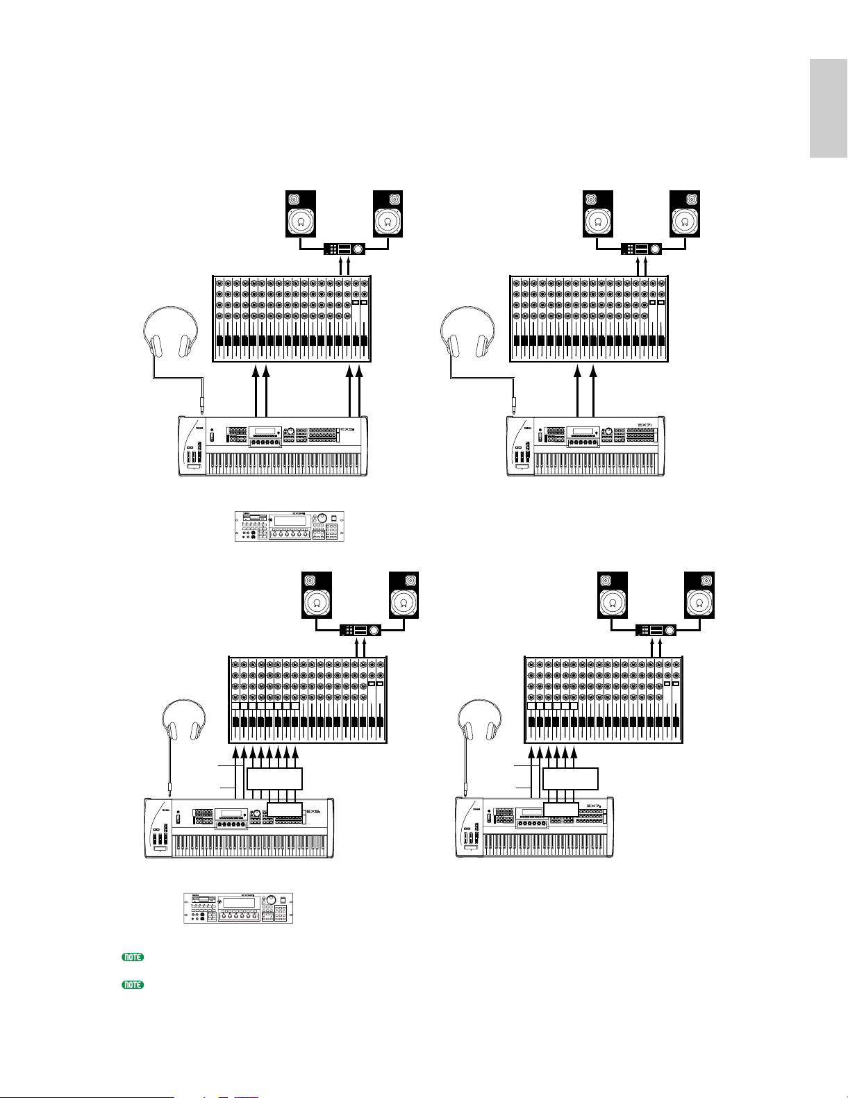
■ Mixing Console
Introductory
Section
In addition to the stereo OUTPUT L/MONO and R jacks, the EX5 and EX5R initially have two
individual outputs: the INDIVIDUAL OUTPUT 1 and 2 jacks. An additional four individual
outputs (3 through 6) can be added by installing the optional EXIDO1 Individual Output Board.
The stereo and individual outputs can be fed to separate channels of a mixing console for
individual processing. Individual “parts” of a performance setup can be assigned to different
individual outputs via the PERFORMANCE EDIT mode PART display (see page 164).
Speakers
OUTPUT L
INDIVIDUAL
OUTPUT 1
MUSIC SYNTHESIZER
REALTIME CONTROL
EXTENDED SYNTHESIS
Amp
R
INDIVIDUAL
OUTPUT 2
MUSIC SYNTHESIZER
REALTIME CONTROL
EXTENDED SYNTHESIS
R
Headphones
L
Mixer
Headphones
1 2 3 4 5 6 7 8 9 10 11 12 13 14 15 16 L R
OUTPUT
PHONES PHONES
L/MONO
R
EX5
EX5R
1 2 3 4 5 6
or
Speakers
Speakers
L
Mixer
1 2 3 4 5 6 7 8 9 10 11 12 13 14 15 16 L R
OUTPUT
L/MONO
AMP
OUTPUT L
R
EX7
Speakers
R
R
MUSIC SYNTHESIZER
REALTIME CONTROL
EXTENDED SYNTHESIS
Mixer
L
OUTPUT L
Amp
R
R
Mixer
L
OUTPUT L
Amp
R
R
HeadphoneHeadphone
OUTPUT
L/MONO
1 2 3 4 5 6 7 8
1 2 3 4 5 6 7 8 9 10 11 12 13 14 15 16 L R
R
INDIVIDUAL
OUTPUT
123456
MUSIC SYNTHESIZER
REALTIME CONTROL
EXTENDED SYNTHESIS
EX5
or
EX5R
1 2 3 4 5 6
MUSIC SYNTHESIZER
REALTIME CONTROL
EXTENDED SYNTHESIS
EXIDO1
OUTPUT
PHONESPHONES
L/MONO
1 2 3 4 5 6
1 2 3 4 5 6 7 8 9 10 11 12 13 14 15 16 L R
R
INDIVIDUAL
OUTPUT
1234
EXIDO1
MUSIC SYNTHESIZER
REALTIME CONTROL
EXTENDED SYNTHESIS
EX7
See page 278 for details on installation of the EXIDO1 Individual Output Board.
The EXIDO1 Individual Output Board and EXDGO1 Digital Output Board use the same option slot, so only
one can be installed at a time.
19
Page 20
Introductory
Section
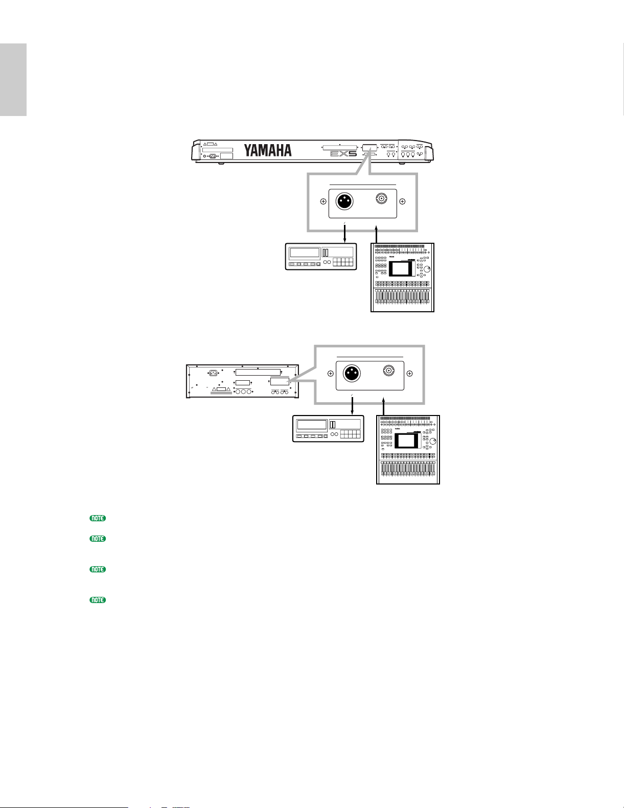
■ Digital Audio (Option)
The optional EXDGO1 Digital Output Board provides an AES/EBU-format digital output which
can be directly connected to an external digital recorder, mixing console, or other digital processing
equipment. This allows the EX sound to be recorded or processed with maximum quality. The
EXDGO1 Digital Output Board also includes a WORD CLOCK IN connector for precise digital
audio synchronization with the external digital devices.
EX5/7
INDIVIDUAL OUTPUT
6543
DIGITAL OUTPUT WORD CLOCK IN
AES EBU
DAT
DAT
O3D
INDIVIDUAL OUTPUT
EX5R
AC INLET
DAT
6543
DIGITAL OUTPUT WORD CLOCK IN
AES EBU
DAT
O3D
See page 278 for details on installation of the EXDGO1 Digital Output Board.
The EXDGO1 Digital Output Board and EXIDO1 Individual Output Board use the same option slot, so only
one can be installed at a time.
When connecting the EXDGO1 (Digital Output AES/EBU [XLR] jack) and an external audio device, use the
XLR cable with the impedance characteristics, 110 Ω.
When receiving word clock from an external audio device, you are required to connect the EXDGO1 (Word
Clock In [BNC] jack) and the external audio device. In this case, use the BNC connector/coaxial cable with
the impedance characteristics, 75 Ω.
20
Page 21
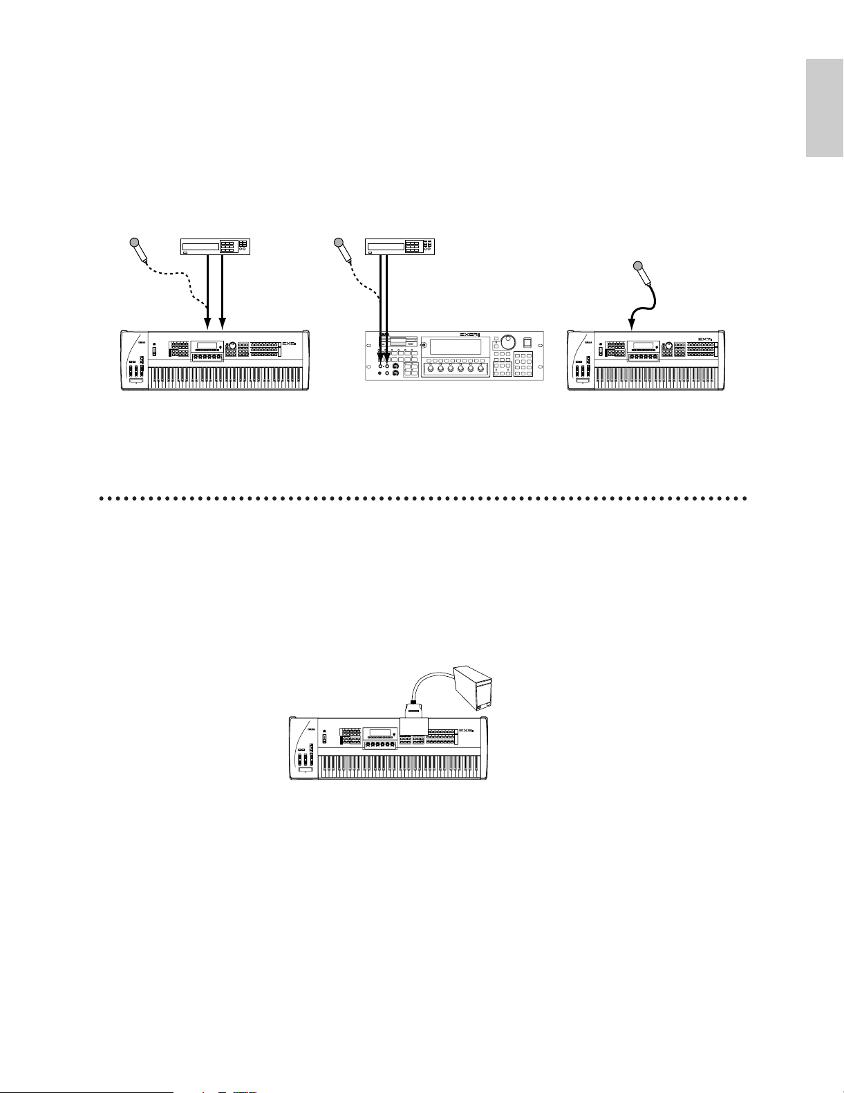
■ External Sampling Sources
EX5/5R/7
MUSIC SYNTHESIZER
REALTIME CONTROL
EXTENDED SYNTHESIS
Hard Disk, etc.
SCSI
ASIB1
MUSIC SYNTHESIZER
REALTIME CONTROL
EXTENDED SYNTHESIS
Audio Device (Stereo)
AD INPUT
L / MONO
R
AD INPUT
L / MONO
R
Mic
(MONO)
RL
Audio Device (Stereo)
Mic
(MONO)
RL
MUSIC SYNTHESIZER
REALTIME CONTROL
EXTENDED SYNTHESIS
1 2 3 4 5 6
EX5R
EX7EX5
Mic
(MONO)
MUSIC SYNTHESIZER
REALTIME CONTROL
EXTENDED SYNTHESIS
AD INPUT
Introductory
Section
The Sampling mode can be used to sample external audio sources as well as internal voice data.
The external source can be either a line-level source such as a CD player or other audio playback
device, or a microphone for direct sampling of live sound. Line and microphone sources should be
connected to the AD INPUT jacks. Line or microphone input sensitivity is switched via the
“line/mic” parameter in the Sample mode REC display (page 176), and fine input sensitivity
adjustment can be carried out via the A/D GAIN control on the control panel. See page 70 for
details.
SCSI Interface (Option)
When the optional ASIB1 SCSI Interface Board is installed (see page 278) the EX5, EX5R, or EX7 can
be connected directly to an external SCSI data storage device for high-speed, high-volume data storage
and retrieval, and/or to a personal computer to allow data transfer between the EX and the Yamaha
Wave Editor application (separately available) running on the computer.
When connected to an appropriate external storage device — hard disk, ZIP, or JAZZ drive (see
“NOTES,” below) — the storage device can be formatted by the EX5, EX5R, or EX7 via the Disk
mode Device Format display (page 269). Voice, performance, song, pattern, arpeggio, wave and other
data can then be saved to and loaded from the hard disk as required via the Disk mode functions
described on page 259.
21
Page 22
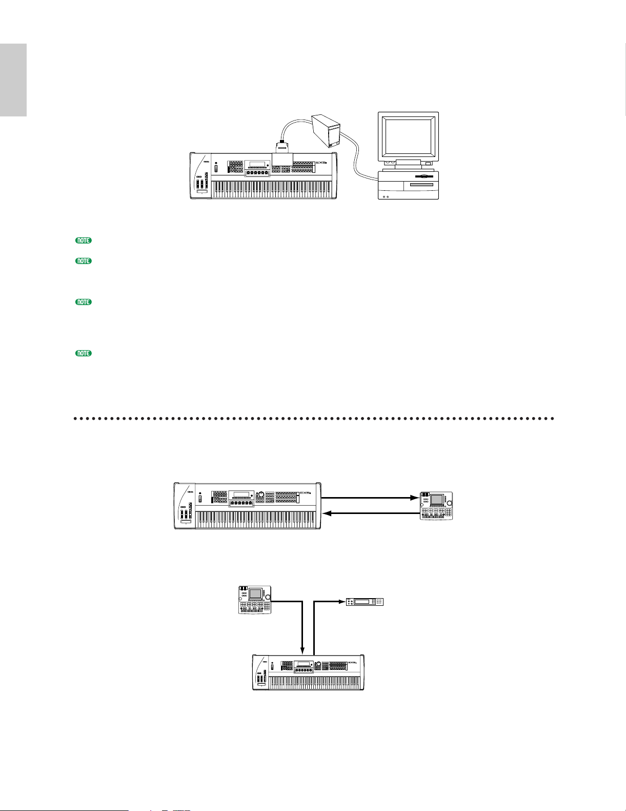
When connected to a personal computer (MacOS® or Windows®), either directly or “chained” via an
MIDI IN
MIDI
THRU
MIDI OUT
MIDI IN
EX5/5R/7
Sequencer Synthesizer/
Tone Generator
MUSIC SYNTHESIZER
REALTIME CONTROL
EXTENDED SYNTHESIS
MIDI IN
MIDI OUT
MIDI IN
MIDI OUT
EX5/5R/7
Sequencer
MUSIC SYNTHESIZER
REALTIME CONTROL
EXTENDED SYNTHESIS
Introductory
Section
external hard disk (see “NOTES” regarding SCSI ID numbers, below), wave data can be transferred
from the EX5, EX5R, or EX7 to the computer, edited using the Yamaha Wave Editor TWE application
(saparately available), and then transferred back to the EX5, EX5R, or EX7.
Hard Disk
SCSI
ASIB1
MUSIC SYNTHESIZER
REALTIME CONTROL
EXTENDED SYNTHESIS
EX5/5R/7
Computer
See page 278 for details on installation of the ASIB1 SCSI Interface Board.
Please note that since the EX5, EX5R, and EX7 use a proprietary data format, the external hard disk must be
formatted by the EX5, EX5R, or EX7 to allow direct data storage and retrieval. The EX5, EX5R, or EX7 will not
directly write to or read from a hard disk formatted by any other computer or device, and vice-versa.
When connecting the EX5, EX5R, or EX7 to a personal computer and/or hard disk via the SCSI interface, make
sure that the EX5, EX5R, or EX7 SCSI ID number — set via the UTILITY mode Other Setup display (page 276)
— does not conflict with any other SCSI device in the SCSI chain. In other words, no two devices in the SCSI
chain should be set to the same SCSI ID number.
The ASIB1 SCSI Interface Board only has a single SCSI connector and thus must be connected at the end of the
SCSI chain (the ASIB1 interface is internally terminated).
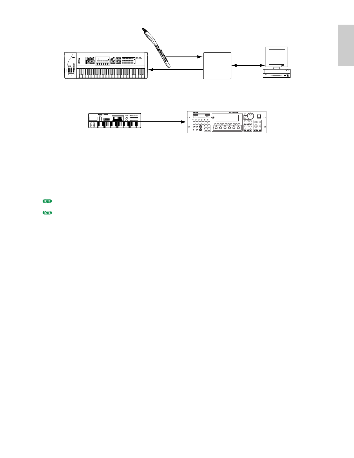
MIDI Connections
Like any other MIDI instrument the EX5, EX5R, and EX7 can be used with MIDI tone generators,
sequencers, computer software, and controllers for virtually unlimited system expansion and control
capability. You might, for example, like to control it from a Yamaha wind controller such as the WX11
rather than the keyboard for even more realistic wind-instrument feel and expression.
22
Page 23
MUSIC SYNTHESIZER
Introductory
Section
REALTIME CONTROL
EXTENDED SYNTHESIS
MIDI IN
MIDI
Interface
Computer
EX5/5R/7
MIDI IN
MIDI OUT
The EX5R Tone Generator will additionally require an external MIDI master keyboard or other MIDI
controller.
MUSIC SYNTHESIZER
REALTIME CONTROL
EXTENDED SYNTHESIS
EX5R
MIDI Master Keyboard
or
Synthesizer
MIDI
OUT
MIDI IN
1 2 3 4 5 6
To ensure reliable error-free transmission of MIDI data always use high-quality MIDI cables obtained
from your Yamaha dealer or music equipment store. Also avoid MIDI cables that are longer than about
15 meters, since cables longer than this can pick up noise which can cause data errors.
The EX MIDI receive channel, device number, local on/off, and other parameters are available in the
UTILITY mode MIDI display described on page 274. Make sure these parameters are set to match the
corresponding settings of the external MIDI device(s) used.
For detailed MIDI specifications refer to the “MIDI Data Format” in the Data List book.
When using the EX5, EX5R, or EX7 with other MIDI equipment, it is a good idea to refer to the MIDI
specifications (implementation chart, MIDI data format) of the equipment used to ensure compatibility.
23
Page 24
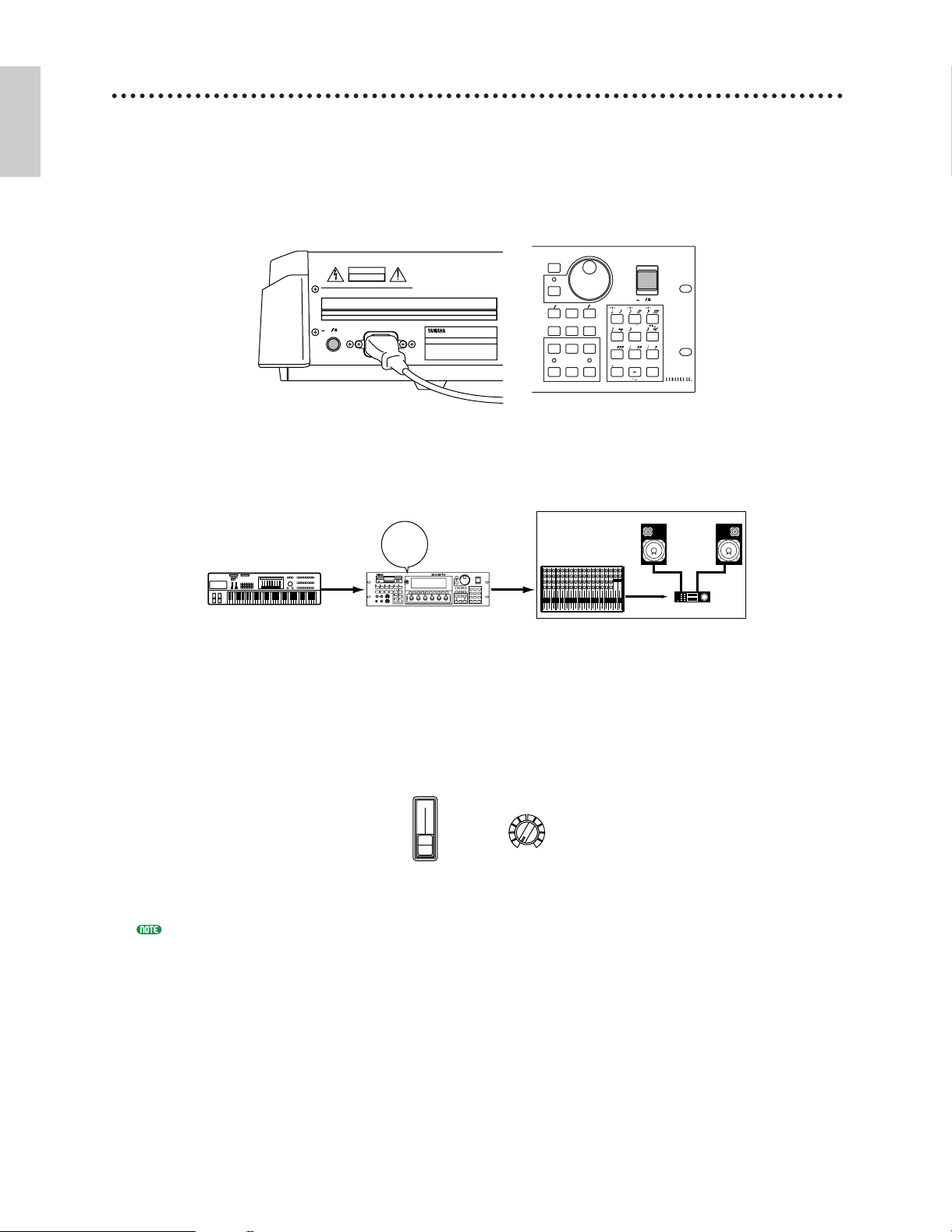
Power-on Procedure
Introductory
Section
Always follow proper procedure when powering-up a sound system to minimize the possibility of
damage to the equipment (and your ears!).
1 Make sure your sound system's main level/volume control(s) and the EX volume control are
turned all the way down prior to turning power on.
2 Turn on the EX5, EX5R, or EX7.
CAUTION
ATTENTION
:RISQUE DE CHOC ELECTRIQUE NE PAS OUVRIR.
WARNING
TO REDUCE T HE RISK OF FIRE OR ELECTRIC
SHOCK,DO NOT EXPOSE THIS PRODUCT TO RAIN OR MOISTURE.
AC INLET
POWER
OFF
ON
EX5/7 EX5R
3 Turn on the sound system.
POWER
ON!!
MIDI Device
Output
Input
1 2 3 4 5 6
EX5/5R/7
MUSIC SYNTHESIZER
REALTIME CONTROL
EXTENDED SYNTHESIS
4 Raise the sound system volume to a reasonable level.
CANCEL
CURSOR
DATA
DEC NO INC YES
REW FWD
TOP
REC STOP PLAY
12345678910111213141516LR
Audio Device
POWER
ON OFF
789
VWX YZ
456
PQR
STU
MNO
123
DEF GHI JKL
ENTER
0
ABC
SPACE
5 Gradually raise the EX VOLUME control while playing the keyboard to set the desired
listening level.
VOLUME
VOLUME
EX5/7 EX5R
The EX5, EX5R, and EX7 automatically transmits MIDI control change data corresponding to its control
status when its power switch is turned ON or OFF. This can interfere with operation of other MIDI
equipment connected to the EX MIDI OUT connectors. If the EX5, EX5R, or EX7 is transmitting MIDI data
to other MIDI equipment, the EX power switch should be turned ON before, and turned OFF after the power
switche(s) of the receiving MIDI device(s).
24
Page 25
Introductory
Section
The Supplied Disks, Demos
MODE
VOICE
PERFORMANCE
SONG
PATTERN SAMPLE
EDIT
JOB STORE UTILIT Y DISK
VOICE PERFORM SONG PATTERN SAMPLE
JOB
LMONO R
BREATH PHONES
VOLUME
AD
INPUT
A D GAIN
STORE UTILIT Y
DISK
SC2
SC1
EDIT
COMPARE
KEYMAP BYPASS
ARPEG KNOB
EX5/7 EX5R
& Factory Set Data
The EX5, EX5R, and EX7 are supplied with four Demonstration Disks containing various
types of pre-programmed demo data which will give you an idea of some of their advanced
capabilities, as well as provide a number of programming examples that may help you to create
the type of sound you need. Each disk contains an all-data file (suffix “.S1A”) containing a
demonstration song, and a Factory Set file (file name: “FACTSET1/2/3/4.S1Y”) containing the
original factory pre-programmed voices and performance setups.
Try loading these files and playing the songs, patterns, arpeggios, voices, performance setups,
or samples they contain. Full disk loading details are provided on page 259, but to get you
started, here’s the procedure for loading and playing the demo songs.
For information on restoring the Factory Set data, see “Restoring the Factory Set Data,” below.
Load and Play the Demo Songs
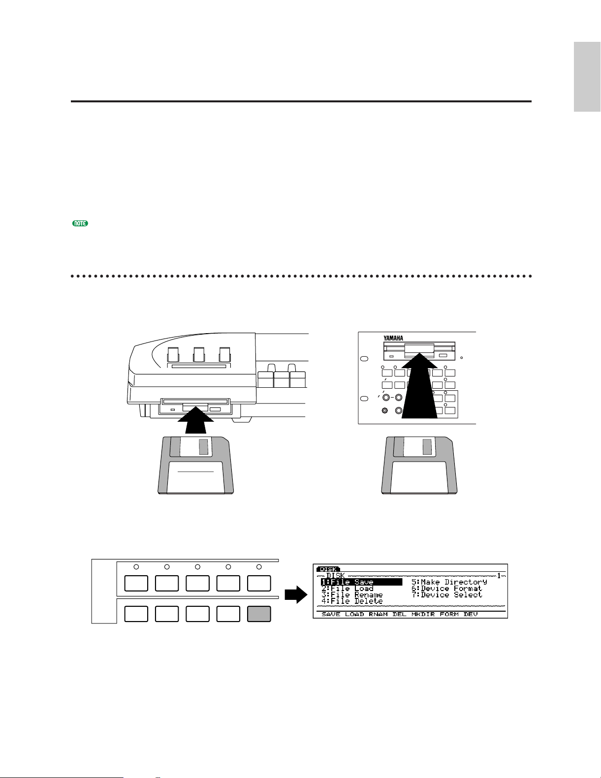
1 Insert the Demonstration Disk
Insert the Demonstration disk in the EX floppy disk drive (shutter first, label side up).
2 Engage the Disk mode
Press the [DISK] key to engage the Disk mode.
25
Page 26
3 Select File Load
Introductory
Section
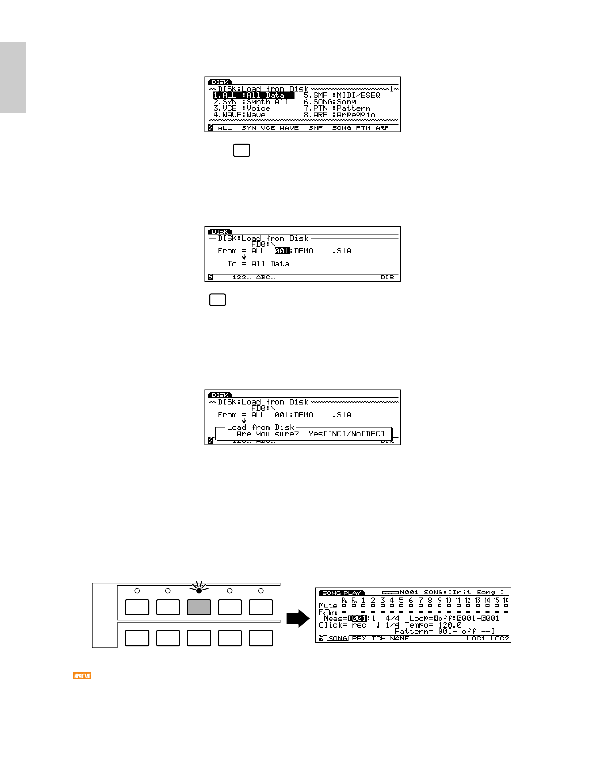
Press the [F2] function key to go to the File Load menu.
F2
4 Select All Data
Press the [F1] function key to select All Data. Please note that all-data files have the suffix “.S1A”
appended to the file name.
F1
5 Select a file and load
Use the Data Dial, [DEC]/[INC] keys, or numeric keypad to select a file number (all of the files on
the Demonstration disk contain different demo songs), then press the [ENTER] key. A
confirmation display will appear.
Press the [INC/YES] key to confirm and load the data.
6 Play the song
When the file has finished loading, first press the [PERFORM (ANCE)] key to select the
Performance mode, next press the [SONG] key to go to the Song mode, and then press the
sequencer PLAY [F] key to start playback of the loaded demo song. Playback will stop
automatically when the song has finished, but you can also stop playback at any time by pressing
the STOP [J] key.
VOICE
PERFORMANCE
MODE
EDIT
JOB STORE UTILIT Y DISK
Before playing “DEMO2” song, press the [KEYMAP] key to engage the Key Map mode. To Play the
Demonstrations other than “DEMO2,” always turn the Key Map mode off (pressing the [KEYMAP] key
again cancels the Key Map mode).
SONG
PATTERN SAMPLE
7 Try other demo files
Go back to the Disk mode and load other files to play the songs they contain.
26
Page 27
Introductory
Section
Restoring the Factory Set Data
CAUTION
ATTENTION
WARNING
:RISQUE DE CHOC ELECTRIQUE NE PAS OUVRIR.
TO REDUCE T HE RISK OF FIRE OR ELECTRIC
SHOCK,DO NOT EXPOSE THIS PRODUCT TO RAIN OR MOISTURE.
POWER
ON
OFF
AC INLET
CANCEL
CURSOR
DATA
TOP
REC STOP PLAY
POWER
REW FWD
ON OFF
DEC NO INC YES
SPACE
ABC
0
123
456
789
ENTER
DEF GHI JKL
MNO
PQR
STU
VWX YZ
EX5/7
or
EX5R
F8 EXIT
Pressing...
In addition to the preset voices (which cannot be erased or overwritten), the EX5, EX5R, and EX7
come with a range of pre-programmed voices, performance setups, and other data in memory. If you
perform any operations that overwrite the data in memory (including system initialization, below),
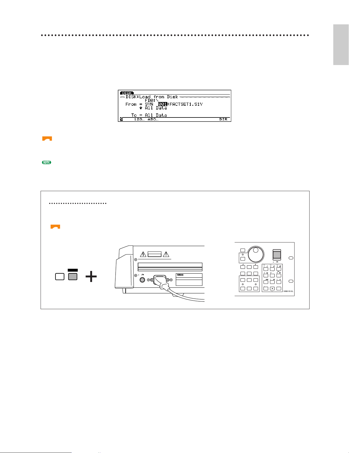
the factory preset data will be lost. If at any time you want to restore the original factory preset data,
simply load the Factory Set file — file name: “FACTSET1/2/3/4.S1Y” — from the appropriate
Demonstration Disk via the Disk mode Load Synth All function (the same procedure described above
except for the file type selection [2. SYN, in this case] for loading the demo song files).
Loading the Factory Set data will overwrite any other data in the EX voice and performance memories!
Be sure to save any internal voices or performances setups you want toe keep to disk before loading the
Factory Set data.
Each of the Demonstration Disk contains different Factory Set files (their contents are the same except for the
voices numbered 1 through 32 in the Internal voice 1). Refer to the separate Data List book (Internal Voice 1)
and choose the disk which contains the appropriate file for your EX5, EX5R or EX7.
System Initialization
To completely erase all data in the EX internal memory and initialize the entire system, turn on the
power while holding the [EXIT] key.
System initialization will erase all data in the EX voice and performance memories! Be sure to save any
internal voices or performances setups you want to keep to disk before initializing the system.
27
Page 28
EX System Overview
Introductory
Section
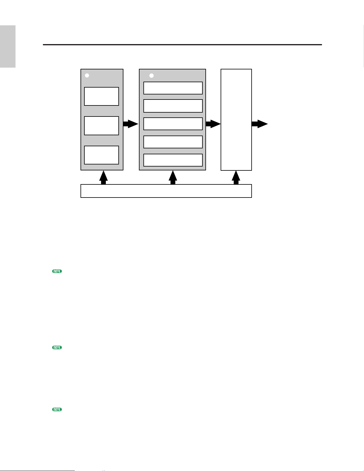
The EX system can be broadly categorized into four main blocks, as shown in the diagram
below:
SEQUENCERS
2
Song
Pattern
Arpeggio
KEYBOARD (EX5 & EX7), CONTROLLERS, MIDI
1
TONE GENERATORS
3
AWM Tone Generator
VL Tone Generator
(EX5 & EX5R only)
AN T one Generator
FDSP Tone Generator
Sampling (wave Data)
EFFECTS
4
SOUND
OUT
1 The keyboard, controllers, and MIDI control.
The EX5 and EX7 feature keyboards (76 and 61 keys, respectively) and a range of realtime
controllers not available on the EX5R Tone Generator. Full control is available on the EX5R,
however, via a MIDI master keyboard or other MIDI controller.
2 The sequencers: Song, Pattern, and Arpeggiator.
The EX5, EX5R and EX7 feature and range of sequencing functions that give them many of the
capabilities of a sophisticated music production system without the need for any extra equipment.
See pages 185, 219 and 238 for more information.
3 The tone generators: AWM, VL (EX5/5R only), AN, and FDSP.
Extended Synthesis is simply the most powerful array of tone generation technologies ever
provided in a single keyboard or tone generator unit. Whether you need the outstanding sound and
programmability of AWM synthesis, the unmatched playability and musical response of VL
synthesis (EX5 and EX5R only), beefy analog synthesizer voices, or the most responsive effects
and simulated resonant systems available, you need look no further.
The EX5, EX5R, and EX7 also feature a built-in sampling system which is capable of sampling
sounds from external sources (line or microphone) as well as internal voices.
See pages 77, 107, 112 and 123 for more information.
4 Effects.
The EX effect system is a top-quality digital signal processing system which is capable of producing
effects rivalling and even exceeding those of many separate component effect units in quality. In
the EX5, EX5R, and EX7, effect programming is an integral and important part of voice
programming, and the ability to control specific effect parameters in real time makes them
indispensable for expressive control as well.
See page 65 for more information.
28
Page 29
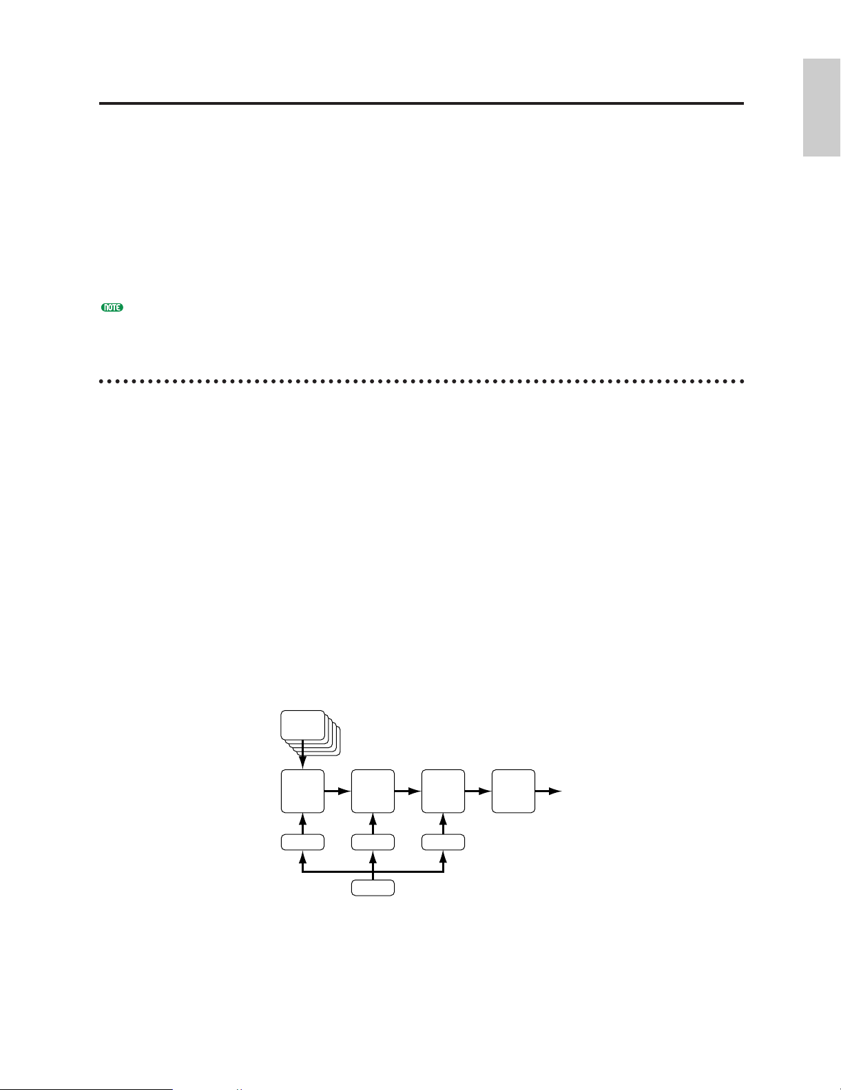
Introductory
Section
Extended Synthesis
SAMPLE
AWM
WAVE
FILTER
AMPLITUDE
EFFECT
PEG FEG
LFO
AEG
Over the years Yamaha has developed a range of industry-leading music synthesis technologies,
each with its individual strengths and advantages. The EX5, EX5R, and EX7 take an
innovative step forward by combining multiple state-of-the-art Yamaha tone generation
technologies in one extraordinarily versatile instrument. When you need the outstanding
sound and programmability of AWM synthesis, it is there. When you need the unmatched
playability and musical response of VL synthesis (EX5 and EX5R only), it is right at your
fingertips. When you want a beefy analog synthesizer voice, you don’t even have to change
keyboards. And when you want the most responsive effects and simulated resonant systems
available, you need look no further.
This is Extended Synthesis: simply the most powerful array of tone generation technologies
ever provided in a single keyboard or tone generator unit.
About the polyphony of each tone generator, see page 45.
AWM Synthesis
AWM, or “Advanced Wave Memory,” is Yamaha’s original system for effectively using sampled
waveforms in synthesizers and tone generators. Although the basis for all AWM voices is a sampled
waveform — a sample of a “real” existing instrument, a classic synthesizer sound, or other
electronically created sounds — the AWM system provides an extensive range of envelope generator,
filter, modulation, and other parameters which can be applied to the basic waveform. Furthermore, up
to four elements, each with its own “wave” and a complete set of editable parameters, can be assigned
to each voice. The strength of AWM synthesis lies not only in its outstanding sound quality (it uses
16-bit, 44.1 kHz samples), but also in its extraordinary ability to “shape” and control the sound of the
samples.
AWM synthesis also allows the creation of “drum voices” in which different drum and percussion
instruments with individual volume, pitch, and timbre parameters can be assigned to individual notes
of the keyboard (from C-2 through G8).
The EX5, EX5R, and EX7 feature a built-in sampling system which is capable of sampling sounds
from external sources (line or microphone) as well as internal voices. Waveforms sampled using this
feature can be used in AWM voices, so your capacity to create totally new AWM voices is truly
unlimited.
■ AWM System Overview
29
Page 30
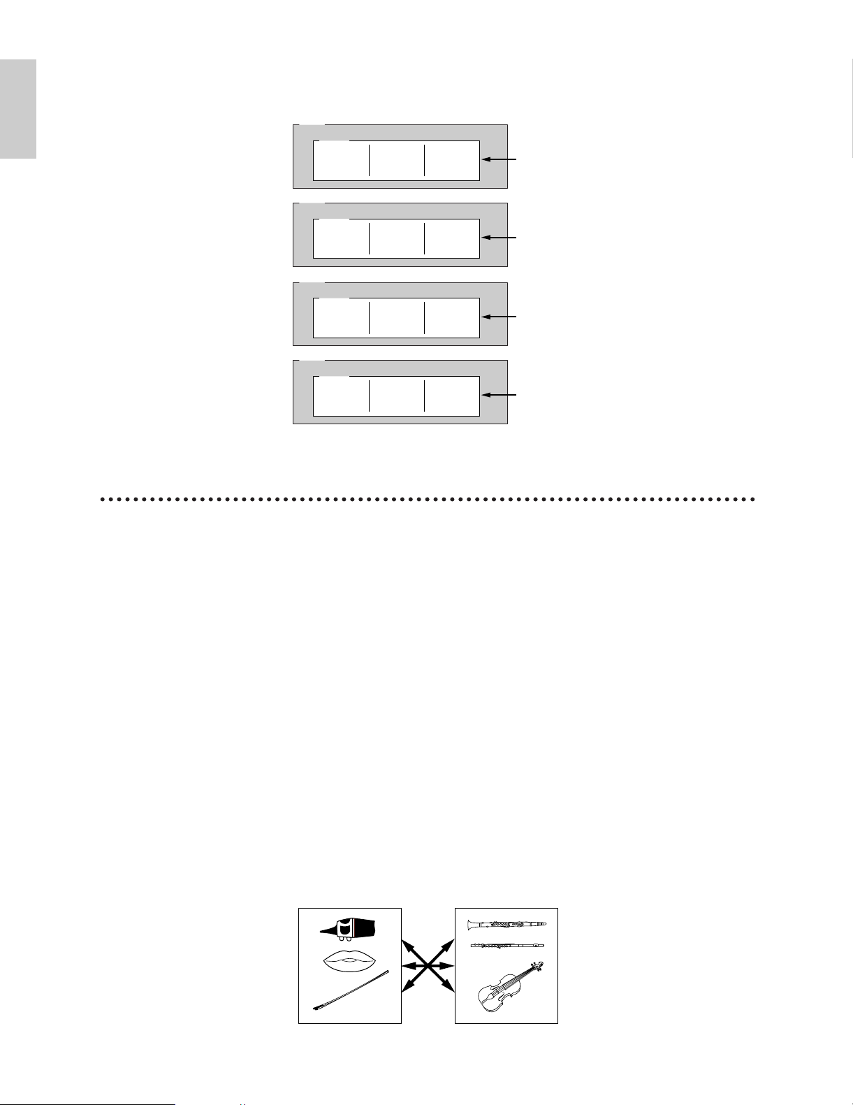
Introductory
Section
■ Layered AWM Voices
Pipes/StringDrivers
EL1
Sample Sample Sample
AWM
WAVE
WAVE parameter
EL2
Sample Sample Sample
AWM
WAVE
WAVE parameter
EL3
Sample Sample Sample
AWM
WAVE
WAVE parameter
EL4
Sample Sample Sample
AWM
WAVE
WAVE parameter
In AWM voices up to four AWM elements can be layered to create extraordinarily rich voice
textures.
Virtual Acoustic Synthesis (EX5 and EX5R only)
Yamaha’s Virtual Acoustic (“VL”) Synthesis tone generation system does not use oscillators, function
generators, preset waveforms or samples to produce sound. Rather, it applies sophisticated computerbased “physical modeling” technology to musical sound synthesis. In the same way that computer
“models” are used to simulate weather systems or the flight characteristics of aircraft in the design
stage, the VL system simulates the very complex vibrations, resonances, reflections and other acoustic
phenomena that occur in a real wind or string instrument.
VL synthesis offers many advantages in terms of musical performance. Not just in terms of sound, but
also in terms of the “behavior” that makes acoustic instruments so “musical.” For example, simply
playing a note in the same way does not always produce precisely the same sound — the instrument is
responsive and “alive.” Rather than simply controlling parameters like volume or pitch, you can
control characteristics such as breath and reed pressure with appropriate complex effects on the
timbre of the sound.
■ The VL “Instrument” or “Wave”
The VL “instrument” or “wave” defines the fundamental tone or timbre of the sound. The
instrument model consists primarily of a driver — the reed/mouthpiece, lip/mouthpiece, or
bow/string system — and a resonant system corresponding to the tube and air column or string.
One of the remarkable features of the Virtual Acoustic Synthesis system is that just about any
driver can be used with any type of pipe or string. The EX5/5R provides a range of 272 preset VL
“waves” which integrate all of the necessary characteristics, and which can be assigned to voice
elements in much the same way as AWM waves (VL voices can have 1 VL element plus up to 3
AWM elements).
30
Page 31

■ Controllers & Modifiers
Throat Formant
Pressure
Growl
Embouchure
Tonguing
Pitch
Scream
Breath Noise
Damping & Absorption
Harmonic Enhancer
Filter
Controls the characteristics of the "player's" throat or bowing arm.
The amount of breath pressure applied to the reed or mouthpiece, or bow velocity applied to the string.
A periodic pressure (bow velocity) modulation which produces the "growl" effect often heard in wind instruments.
The tightness of the lips against the reed or against each other, or the force of the bow against the string.
Simulates the half-tonguing technique used by saxophone players by changing the "slit" of the reed.
Changes the length of the air column or string, and thereby the pitch of the sound.
Drives the entire system into chaotic oscillation, creating effects that can only be achieved with physical modelling
technology.
Adds breath noise to produce exceptionally realistic effects with many wind instruments.
Simulates the effects of air friction in the pipe or on the string, and of high-frequency losses at the end of the pipe or
string.
The Harmonic Enhancer determines the harmonic structure of the sound to the extent that it can produce radical
timbral variations within an instrument "family" (e.g. saxes).
This modifier is similar to the dynamic filters found in many conventional synthesizers, with high-pass, bandpass, band
elimination, and low-pass modes.
Tonguing
Breath Noise
Throat Formant
Scream
Embouchure
Pitch
Damping &
Absorption
Growl
Pressure
Introductory
Section
The input to an acoustic wind instrument comes from the player's lungs, trachea, oral cavity, and
lips. In a string instrument it comes from the player's arm movement, transmitted to the string via
a bow. These factors actually form an important part of the sound generating system and, in the
VL model, are known as “controllers” (note that these are parameters, not physical controllers like
the modulation wheels or knobs). The player also influences the sound of the instrument by
playing the keys, tone holes, or frets, and this aspect of control constitutes another part of the
“controllers” system.
In essence, the controller parameters determine how the instrument “plays.” All of these
parameters can be assigned to any external controller that can be used with the EX5 and EX5R:
Foot Controller, Modulation Wheel, Controller Knobs, Ribbon Controller, Breath Controller, etc.
The pressure parameter, for example, could be assigned to a breath controller so the player can
control the dynamics of the instrument by varying the breath pressure applied to the controller — a
natural, instinctive way to play wind-instrument voices. At the same time the growl and throat
parameters might also be assigned to the breath controller in order to achieve life-like response and
effects.
Modifiers, such as the Harmonic Enhancer and Dynamic Filter, are applied after the VL
controllers. Although these may appear to be simple effects, they are actually intimately related to
the VL sound-producing model and have a significant effect on the sound.
Some of the controller and modifier parameters provided by the EX5 and EX5R are listed in the
chart below.
31
Page 32

Introductory
Section
■ VL System Overview
Effects
Elements
1
2
3
4
VL
AWM
AWM
AWM
Element
Driver
Pipe/String
● Pipe (Single-ended)
● Pipe (Double-ended)
● String
● Mouthpiece
● Embouchure
● Bow (for strings)
Modifier Effect
■ VL + AWM Voices
A single VL element can be combined with up to three AWM elements.
32
Page 33

Introductory
Section
AN Synthesis (Analog Physical Modeling)
VCO 1
Mixing
VCF
AMP
NOISE
LFO
RING
MODULATER
MASTER SLAVE
SYNC
FM
VCO 2
VCO
Increases/decreases
harmonic overtones.
Increased: brighter sound
Decreased: softer sound
Filter
Adjusts amplitude over time
small
large
Amplifier
LFO wave LFO applied
Original wave
FEEDBACK
Although synthesizers have come a long way since the days of VCOs (Voltage Controlled Oscillators),
VCFs (Voltage Controlled Filters), and VCAs (Voltage Controlled Amplifiers), modern digital tone
generators can’t quite reproduce the punch, power, and interactive control capabilities of such older
systems. Yamaha AN Synthesis (Analog Physical Modeling), however, offers all the benefits of
traditional analog synthesis with the stability, reproduceability, and precise control of digital
technology. It is capable of accurately reproducing the sound of classic analog synthesizer without
patch cables, setting charts, or the frustrating instability that was the bane of the analog age. AN
Synthesis also offers many features that were simply not possible in pure analog systems. It is, for
example, also capable of FM synthesis similar to the type that made the legendary Yamaha DX7 one of
the most popular synthesizers of all time.
In addition to single-element AN voices, the EX5 and EX5R allow two AN elements to be layered to
create even thicker analog synth sounds.
■ AN System Overview
33
Page 34

Introductory
Section
■ AN (Poly)+AWM Voices
note dependent note dependent
Delay Delay
Integ
Magnetic Field
Distance
Diff
LPF
Cutoff/
Resonance
Output
Input
Picking position Pickup Position
HPF
Highpass
Filter
bypass
Emp
Pickup type
Flet
control
picking notch
pickup
notch
Drive
Effects
Elements
1
2
3
4
AN
AWM
AWM
AWM
Effects
Elements
1
2
3
4
AN
AN
AWM
AWM
■ AN (Layer)+AWM Voices
As shown in the diagrams below, a single AN element can be combined with up to three AWM
elements in AN(Poly)+AWM voices. In the EX5 and EX5R, two AN elements can be combined
with up to two AWM elements in AN(Layer)+AWM Voices. AN + FDSP voices are described in
the FDSP Synthesis section, below.
FDSP Synthesis
(Formulated Digital Signal Processing)
FDSP, or “Formulated Digital Sound Processing,” is actually an adjunct to AWM synthesis. It adds a
sophisticated note-dependent effect processor to the basic AWM synthesis system. In contrast to a
standard effect stage, the FDSP synthesis stage uses individual note and velocity data to control effect
parameters, thus making it possible to simulate the characterics of a number of real-world musical
components, as well as produce totally new effects. For example, FDSP can effectively model the
frequency and velocity dependent characteristics of electromagnetic guitar or piano pickups, thus
adding more realistic response to these types of voices, or adding a whole new dimension to other
sounds. It can also alter the delay time of flange or chorus type effects according to the note played,
thus producing totally new sounds that are responsive and “alive.” Many other effects are possible.
■ FDSP System Overview
This block diagram is only one example of an FDSP configuration. In this case the FDSP system is
used to model the response of an electric guitar pickup.
34
Page 35

Introductory
Section
■ FDSP Voice Element Structure
1
2
3
4
AWM
AWM
AWM
AN
Effects
Elements
FDSP Unit
Effects
Elements
1
2
3
4
AWM
AWM
AWM
AWM
FDSP Unit
In an FDSP voice up to four AWM elements can be fed to the FDSP stage or routed directly to the
normal effect stage as required.
■ AN+FDSP Voices
AN+FDSP voices allow a single AN element to be layered with up to three AWM elements feeding
the FDSP stage.
35
Page 36

Introductory
Section
Voice & Performance
MODE
VOICE
PERFORMANCE
SONG
PATTERN SAMPLE
EDIT
JOB STORE UTILIT Y DISK
Function Menu
Bank &
Number
Performance
Number
Performance Name
MODE
VOICE
PERFORMANCE
SONG
PATTERN SAMPLE
EDIT
JOB STORE UTILIT Y DISK
Function MenuVoice Type
(See “Extended
Synthesis”, page 29)
Memory
area
Receive
Channel
Transmit
Channel
Bank &
Number
Voice
Number
Voice Name
Selection
One of the first things you'll want to do with your EX5, EX5R, or EX7 is select and play some
of its voices or performance combinations … this section will show you how to do just that.
The EX has 256 preset voices organized into two separate memories — Preset 1 (“P1”), and
Preset 2 (“P2”) — each containing 128 voices. Two 128-voice “Internal” memory areas are
also provided for storage of original voices or voices loaded from an external storage medium:
Internal 1 (“I1”) and Internal 2 (“I2”). The EX voice memory can thus hold up to 512 voices
at once for instant selection and performance.
One internal 128-location memory area is provided for performance combinations, so there’s
no need to switch memory areas as in the Voice mode.
If at any time you want to restore the original factory voices, they can be reloaded from the supplied Factory Set
file as described on page 27.
1 Select the Voice or Performance Mode
To select and play voices, press the [VOICE] MODE button so that its indicator lights and “VOICE
PLAY” appears in the upper left corner of the LCD screen. The voice-mode display provides a few
items of information in addition to the name of the currently selected voice.
The abbreviations in the section separated by a line at the bottom of the display (“P1,” “P2,” etc)
indicate the functions of the corresponding function keys below the display screen.
To select and play performance combinations press the [PERFORMANCE] MODE button so that its
indicator lights and “PERFORM PLAY” appears in the upper left corner of the LCD screen. The
performance-mode display is somewhat simpler than the voice mode display.
36
Page 37

Introductory
Section
2 Select a Voice or Performance
In the Voice mode the P1, P2, I1, and I2 memory areas can be directly selected by pressing the
corresponding function key, [F1] through [F4], and successively pressing [ENTER] key.
Each memory area contains 8 banks of 16 voices each (8 x 16 = 128). The Performance mode has
just one 128-location memory area. On the EX5 and EX7, any voice or performance in the current
memory area can be selected by specifying its bank using the BANK keys ([A] through [H]), and its
number using the PROGRAM number keys ([1] through [16]). To select voice or performance
“D7” (number 55), for example, first press the bank [D] key and then the program number [7] key.
The bank [D] key indicator will flash until the program number [7] key is pressed and the D7 voice
or performance is actually engaged.
ABCDEFGH
12341234
12345678
COMMON OSC PITCH FILTER AMPLITUDE LFO CONTROL EFFECT
9 10111213141516
ELEMENT SELECT ELEMENT ON OFF
BANK
PROGRAM
PAR T
TRACK
The Data Dial and [DEC]/[INC] keys, as well as the numeric keypad, can be used to select voices
and performance setups on the EX5R (see “Alternate Selection Methods,” below).
CANCEL
89
STU
ENTER
SPACE
CURSOR
DATA
DEC NO
INC
7
VWX YZ
456
MNO PQR
YES
123
DEF GHI JKL
0
ABC
The number of the selected voice or performance will appear in the upper left corner of the display. Note that
each voice or performance in the active memory area can be referred to in two ways: as a decimal number
from 1 to 128, or as a bank and number (A1…A16, B1…B16, etc, through H1…H16).
To select a different voice or performance within the same bank it is only necessary to press the
appropriate PROGRAM number key. To select a different bank, however, you'll always have to
press both a bank key (followed by [ENTER]) and a program number key.
37
Page 38

Introductory
Section
■ Alternate Selection Methods
F7
F8
The [INC] and [DEC] Keys
The [INC] and [DEC] Keys are best used for small, step-wise changes — e.g. selecting adjacent
voice or performance numbers, or numbers that are only a few steps away. Press the [DEC] or
[INC] key briefly to decrement or increment the number by one, or hold either key for continuous
decrementing or incrementing in the corresponding direction.
The Data Dial
The Data Dial provides a fast, efficient way to cover a broad range of numbers when, for example,
you’re looking for a voice or performance but don’t know the exact number. Simply rotate the data
dial clockwise for higher numbers or counter-clockwise for lower numbers while watching the
screen.
The Numeric Keypad
The number keys are an excellent choice when you know the decimal number of the voice or
performance you want. Simply enter the number (“1” through “128” using 1, 2, or 3 digits as
required), then press the [ENTER] key to actually select the voice or performance.
■ The Voice/Performance Directory
The voice/performance directory shows the names of 16 voices or performances at a time, with the
cursor located at the currently selected number. To switch to the directory display, press the [F8]
button — located directly below “DIR” on the display. Voices and performances are selected using
the same methods described above, as well as by using the cursor keys to highlight the number and
name of the desired voice or performance.
When the voice directory is initially selected the voice names are preceded by the corresponding
voice number. By pressing the [DIR] function key a second time, however, the voice numbers are
replaced by the voice category abbreviation for that voice (“Pf” for piano, “Or” for organ, etc). A
complete list of the voice categories is provided on page 76.
To return to the normal voice or performance display press the [EXIT] button.
■ Selecting By Category
In both the Voice and Performance modes the [F7] function key is marked “[CTG],” for “Category.”
Press the [CTG] function key to select voices belonging to the same category (e.g. all piano voices
in the “Pf” category) in sequence, beginning with the currently selected voice.
38
Page 39

Introductory
Section
Normal Voices & Drum Voices
Rev
Cho
Ins
Rev
Cho
AN
Rev
Cho
AWM AN (Poly) FDSP
FDSP
DSP1
One of the followings can be selected
Rev
Cho
Ins
Ins
Ins
Ins
VL
AN
AN
FDSP
FDSP
VL
+
AWM
AWM AN (Poly)/
AN (Layer)
AN
+
FDSP
FDSP
DSP2
One of the followings can be selected
DSP1
Exclusive to
the effects
AWM voices can be divided into two groups : normal voices and drum voices.
• A normal voice is simply a pitched voice which can be played on a musical scale from low to high,
such as a piano or trumpet.
• A drum voice is a complete set of drum and other percussion sounds, each having a fixed pitch and
being assigned to individual notes of the keyboard (from C-2 through G8). When initially shipped
from the factory, EX instruments have 9 drum voices, numbered 123 through 128 in the Preset 2
bank and 126 through 128 in the Internal 2 bank (see the separate Data List for details). You can
also create your own drum voices (page 141).
DSP Limitations
The DSP (Digital Signal Processing) system used to create the EX effects is also used by the AN,
FDSP, and VL (EX5/5R only) tone generators to create voices. This means that less DSP capacity is
available to produce effects when the aforementioned voice types are used. This imposes limitations
which are different for the EX5/5R and EX7. The Reverb and Chorus effect units function normally
regardless of the type of voice used.
EX5/5R
There are no limitations to using insertion effects in the EX5 or EX5R Voice mode. In the
Performance mode, however, insertion effects can be used on a maximum of 4 parts (voices) if the
performance setup consists entirely of AWM voices. If a VL, AN, or FDSP voice is used in the
performance setup, however, an insertion effect can only be used on one part (voice).
EX7
In the EX7 Voice mode, Insertion effects can be used in AWM voices, but not in any other voice type
(AN or FDSP). In the Performance mode, if the performance setup consists of only AWM voices,
then an insertion effect may be used on one voice. But if the performance setup includes an AN or
FDSP voice, then no insertion effects can be used.
39
Page 40

Introductory
Section
Voice Structure & Editing Hints
Although the EX Extended Synthesis tone generator system is quite complicated, the overall system
and interface have been designed to make voice editing as easy and efficient as possible. A thorough
understanding of the system will depend on familiarity with the individual parameters connected with
each tone generator type (see list, below), but in this section we’ll provide some information that may
help in grasping how everything fits together, and perhaps in developing an organized approach to
voice editing on the EX5/5R/7.
For details on the individual parameters connected with each tone generator type, see the following
pages:
AWM Parameters ............................Page 75
VL Parameters ..................................Page 107
AN Parameters ................................Page 112
FDSP Parameters..............................Page 123
System Overview
■ Individual Element Structure
Any EX voice, no matter what tone generator type it uses, can have anywhere from one to four
“elements.” The structure of each element consists of four “stages” as shown in the block diagram
below.
OSCILLATOR
PITCH
FILTER
AMPLITUDE
Although the individual parameters available in each stage will vary to some degree depending on
the type of tone generator being edited, the basic function of each stage is the same.
OSCILLATOR
This stage is not really an “oscillator” in the traditional sense of the word, but it is here that the
basic sound of the voice is produced.
● In an AWM element, the “oscillator” is the waveform or sample on which the voice is based.
● In a VL element (EX5/5R only), it is the instrument model: the reed/mouthpiece,
lip/mouthpiece, or bow/string system plus the resonant system corresponding to the tube and
air column or string.
● In an AN element it is the simulated VCO (Voltage Controlled Oscillator) of the simulated
analog synthesis system.
● Since FDSP elements are based on AWM synthesis, an AWM oscillator stage is the same as in
an AWM element.
AWM OSCILLATOR parameter details begin on page 80.
VL OSCILLATOR parameter details begin on page 108.
AN OSCILLATOR parameter details begin on page 113.
40
Page 41

Introductory
Section
PITCH
The PITCH stage determines the pitch of the sound. In addition to allowing the pitch of the voice
to be controlled from the keyboard or via MIDI note data, it allows pitch control from the pitch
bend wheel, keyboard aftertouch, or any other assignable controller. The PITCH stage also includes
programmable pitch envelope generators which can be programmed to produce time-based pitch
variation, as well as key scaling parameters which can be used to produce different tuning curves.
AWM PITCH parameter details begin on page 83.
VL PITCH parameter details begin on page 108.
AN PITCH parameter details begin on page 117.
FILTER
This stage controls the filters provided for the selected tone generator type, and thus allows both
static and dynamic timbral control. Dynamic filters can be set to respond to keyboard touch
response or other controllers, while filter envelope generators can produce time-based timbral
variation. The type and number of filter parameters available varies considerably according to the
selected tone generator type.
AWM FILTER parameter details begin on page 86.
VL FILTER parameter details begin on page 109.
AN FILTER parameter details begin on page 118.
AMPLITUDE
This stage includes all parameters which affect the amplitude or volume level of the sound,
including basic level control, touch dynamics, keyboard level scaling, and amplitude envelope
generation.
AWM AMPLITUDE parameter details begin on page 96.
VL AMPLITUDE parameter details begin on page 110.
AN AMPLITUDE parameter details begin on page 119.
41
Page 42

Introductory
Section
■ Overall System Structure
If we now put all four elements together, and add in the all-important control and effect blocks, the
system looks something like this:
ELEMENT 1
OSCILLATOR
ELEMENT 2
OSCILLATOR
ELEMENT 3
OSCILLATOR
ELEMENT 4
OSCILLATOR
PITCH
PITCH
PITCH
PITCH
KEYBOARD, CONTROLLERS & LFO
FILTER
FILTER
FILTER
FILTER
AMPLITUDE
AMPLITUDE
AMPLITUDE
AMPLITUDE
EFFECTS
In this diagram note that the KEYBOARD, CONTROLLERS & LFO block affects the PITCH,
FILTER, and AMPLITUDE stages of each element, as well as the EFFECT block.
KEYBOARD, CONTROLLERS & LFO
The EX5 and EX7 keyboards include both initial and aftertouch response which can be used for
realtime control of an extremely wide range of parameters. The EX5R does not have a keyboard,
but it accepts corresponding MIDI data from an external device which can be used to the same
effect. The extremely versatile realtime control assignment system allows just about any controller
to be assigned to any parameter — or multiple parameters, as required — for extraordinary
expressive control. The LFO (in some elements multiple LFOs) can be used for pitch, filter, and/or
amplitude modulation.
CONTROLLER parameter details begin on page 103.
EFFECTS
The EX internal effect system provides an extensive range of programmable effects including
natural reverberation, modulation effects such as chorus and flanging, compression, distortion,
auto-wah, rotary speaker, and much, much more. Controllers can also be assigned to specific effect
parameters for unlimited realtime effect variation.
EFFECT parameter details begin on page 105.
FDSP ELEMENTS
The structure of FDSP elements is just slightly different from those shown above with the addition
of an FDSP stage between the basic AWM element and effect block. The FDSP parameters are
available via the FDSP parameter page which is accessible via the COM (COMMON) parameter
page.
FDSP parameter details begin on page 123.
42
Page 43

Introductory
Section
■ Element Configuration
Voice
Elements 1-4
Element
up to 1024
AWM: 419 presets, up to 1024 waves
FDSP: 419 presets, up to 1024 waves
Wave
AN: VCO1 and VCO 2 waves
VL (VA): 272
Sample
Presets: 1-1484
DRAM/FLASH: 1-1024
■ Element Combinations
Although the various element combinations possible with each voice type were introduced in the
“Extended Synthesis” section (page 29), we’ll cover them again here because they are so pertinent
to the current topic.
Remember that you can create a voice with only one element, or combine as many as four. The
allowable element combinations, listed below, will greatly affect the way you approach voice
editing. The type of element(s) you use will always be your first decision when creating a new
voice.
AWM Voices (EX5, EX5R, and EX7)
AWM voices can have from 1 to 4 AMW elements. If you’re creating an AWM voice, this is
obviously the type to choose. Please note that you also want to start with an AWM element when
you intend to use a wave you have sampled yourself using the Sampling feature, or sampled
waveforms imported from another source. The ability to combine AWM elements means that you
could, for example, combine separate samples for the attack and sustains portions of an
instrument’s sound, with independent control over each.
AWM ELEMENT
AWM ELEMENT
EFFECTS
AWM ELEMENT
AWM ELEMENT
OUT
More on AWM voices on page 77.
VL Voices (EX5 and EX5R only)
VL voices can have 1 VL element and from 1 to 3 AWM elements. In many cases you’ll probably
want to use the VL element alone to emphasize the full realism and expressive power of the VL
tone generator. But the ability to add AWM elements provides an unprecedented measure of
flexibility for thickening and adding depth to the VL sound.
VL ELEMENT
AWM ELEMENT
EFFECTS
AWM ELEMENT
OUT
AWM ELEMENT
More on VL voices on page 107.
43
Page 44

AN(Poly) Voices (EX5, EX5R, and EX7)
Introductory
Section
A standard (Poly) AN voice can have 1 AN element and from 1 to 3 AWM elements. If you’re
striving to create a classic analog synth or FM synthesizer type sound, it is probably better to start
with the single AN element alone. Add AWM elements as necessary to “modernize” the sound.
AN ELEMENT
AWM ELEMENT
EFFECTS
AWM ELEMENT
AWM ELEMENT
OUT
More on AN voices on page 112.
AN(Layer) Voices (EX5 and EX5R only)
AN layer voices can have 1 or 2 AN elements and 1 or 2 AWM elements. When you need a really
thick, powerful pad or a punchy analog type voice, try combining the two AN elements in this
voice type. Once again, the AWM elements are there when you need them to add realistic samples
or other textures.
AN ELEMENT
AN ELEMENT
EFFECTS
AWM ELEMENT
AWM ELEMENT
OUT
FDSP Voices (EX5, EX5R, and EX7)
FDSP voices have from 1 to 4 AWM elements with an FDSP stage between the elements and the
main effect stage. The FDSP stage can be applied to any or all of the AWM elements used, as
required.
AWM ELEMENT
AWM ELEMENT
FDSP EFFECTS
AWM ELEMENT
AWM ELEMENT
OUT
More on FDSP voices on page 123.
44
Page 45

AN+FDSP Voices (EX5 and EX5R only)
Voice Type
AWM/Drum*
VL+AWM
FDSP
AN(Poly)+AWM
AN(Layer)+AWM
AN+FDSP
EX5/5R Polyphony
126
1+AWM
16
2+AWM
1+AWM
AN: 1; FDSP: 8
EX7 Polyphony
64
—
8
1+AWM
—
—
*Please note that the actual polyphony may be reduced under
certain conditions.
AN ELEMENT
FDSP EFFECTS
AWM ELEMENT
AWM ELEMENT
AWM ELEMENT
OUT
Introductory
Section
AN+FDSP voices can have 1 AN element and from 1 to 3 FDSP elements. The FDSP stage can be
applied to any or all of the AWM elements used, as required.
Polyphony
The maximum polyphony of the EX5 and EX5R is 126 notes, and the maximum polyphony of the
EX7 is 64 notes. Full polyphony, however, is not available for all voice types. The chart below lists the
maximum polyphony for each voice type.
Editing Control
The EX5, EX5R, and EX7 provide a number of tools and techniques to facilitate voice editing. Some
of the more important methods are discussed below.
■ Element Selection
When editing a multi-element voice, you will obviously need to select the specific element you
want to edit. On all models this can be done via the edit display, cursor keys and data entry
dial/keys. The EX5 and EX7 additionally allow element selection via BANK select keys [1] through
[4] (labelled “ELEMENT SELECT), corresponding to elements 1 through 4. In the VOICE EDIT
mode pressing any of these keys will select the corresponding element for editing. The currently
selected element is indicated by an inverse element number on the left side of the edit display, and
by a lit indicator above the corresponding ELEMENT SELECT key. Any element can be selected
and enabled as required in the OSC page, but only elements which are on can be selected when any
other editing page is showing. Only one element can be selected at a time.
45
Page 46

■ Element Muting
1 2 3 4 5 6
F1
SHIFT
Introductory
Section
Another necessity when editing a multi-element voice is the ability to turn individual elements off
or on. You might need to concentrate on the sound of a single element, for example, and need to
“mute” any other elements so you can hear only the target element while making subtle changes.
On the EX5 and EX7 individual element muting can be accomplished via BANK select keys [5]
through [8] (labelled “ELEMENT ON/OFF). The key indicators corresponding to elements which
are on will be lit, and will go out when the corresponding element is muted. Muted elements are
also indicated by a small element number on the left side of the edit display.
On all models, individual elements can also be turned on or off while editing by pressing the
correspondingly-numbered key on the numeric keypad while holding the [SHIFT] key.
■ Direct Edit Page Selection
Once you’ve entered the Voice Edit mode, you can directly select each edit page by one of the
following methods: use the [F1] key to select the edit pages in sequence, or select any individual
page by pressing the corresponding function key while holding the [SHIFT] key. On the EX5 and
EX7 all of the top-level edit pages can also be directly accessed via PROGRAM keys [1] through [8]
— corresponding to the COMMON, OSC, PITCH, FILTER, AMPLITUDE, LFO, CONTROL, and
EFFECT parameter pages, respectively (these are marked on the panel below the corresponding
keys.
■ Controller Knob Mode Switching
The Controller Knobs are conveniently set up to act as data entry controls for voice editing. A
small inverse number beside a parameter in the display indicates that the correspondinglynumbered Controller Knob will adjust that parameter.
There will be cases, however, where you’ll want to try out the effect of the Controller Knobs as
they apply to the sound of the voice. Simply press the [KNOB MODE] key so that its indicator
lights to instantly switch the knobs back to sound control. When you’re ready to continue editing,
press the [KNOB MODE] key again so that its indicator goes out to reset the knobs to the data
entry mode.
46
Page 47

Introductory
Section
■ Relative & Absolute Controller Knob Data Entry
Normally when you rotate a Controller Knob being used for data entry, the corresponding value
changes in relative fashion — i.e. the knob increases or decreases the value of the parameter in
relation to the value that was initially on the display. To put it another way, the central detented
position of the Controller Knob will correspond approximately to the parameter value that was on
the display before the knob was rotated.
If you rotate a Controller Knob while holding the [KNOB MODE] key, however, the relationship
between the controller position and the data value becomes absolute, and the central detented
position of the knob will correspond to the exact center of the parameter range.
■ Compare & Store
The moment you alter any parameter in the Voice Edit mode a small inverse “ ” will appear at
the top left on the display, indicating that the voice has been edited but not yet stored.
You can also press the [EDIT/COMPARE] key while in the edit mode to switch back and forth
between the original and edited sound (an inverse “ ” appears at the top left on the display when
the Compare function is engaged — i.e. the original sound is being monitored).
When you exit from the Voice Edit mode the “ ” will remain at the top left on the display until
you either store the edited voice or select a different voice number or mode. If you do select a
different voice number or mode prior to storing the edited voice, the edited data will be lost! So be
sure to store edited voice data you want to keep, as described on page 48.
If at any time you want to restore the original factory voices, they can be reloaded from the supplied Factory
Set file as described on page 27.
47
Page 48

Voice Store Procedure
Introductory
Section
To store an edited voice:
1 Press the [STORE] key
After editing the voice as required, press the [STORE] key either while still in the Voice Edit
mode, or immediately after returning to the Voice Play mode (do not select a different voice or
mode before storing the edited data, or the edited data will be lost!).
SONG
PATTERN SAMPLE
MODE
VOICE
EDIT
PERFORMANCE
JOB STORE UTILIT Y DISK
2 Select the destination voice
Use the Cursor keys in conjunction with the Data Dial, the [DEC]/[INC] keys, the numeric
keypad, or Controller Knob 1 to select the internal Voice memory location to which you want to
store the edited data. The BANK and PROGRAM keys can also be used on the EX5 and EX7.
3 Press [ENTER] and confirm
Press the [ENTER] key. The “Are you sure?” confirmation display will appear. Press the
[INC/YES] key to confirm and actually store th edited data. Press [DEC/NO] if you want to
abort the store operation.
7
V WX Y Z
4 5 6
MN O PQ R
1 2 3
DE F G HI J K L
0
AB C
8 9
ST U
ENTER
SPACE
4 Press [EXIT]
When the data has been stored (“Completed!” will appear briefly on the display), press the
[EXIT] key to return to the previous display.
Up to 1024 elements can be stored onto your EX.
48
Page 49

The Power of the Performance Mode
Introductory
Section
The EX Performance mode allows up to 16 different voices to be assigned to different “parts” and
combined in a number of ways. The results can be ideal for real-time performance — as the name of
the mode suggests — or for sequencing via the EX Song or Pattern mode, or via external MIDI
control. Either way, the Performance mode offers versatility and control not available in the Voice
mode.
Performance
Part 1~16
Plays layered
voices
Layer Switch: ON
=
Performance
Song/Pattern
Sequencer
MIDI CH
1~16
Part 1~16
CH1
CH16
Plays each part
(voice)
■ Layers
Two different voices (know as “parts” in the Performance mode) can be combined in layers and
played simultaneously. Independent volume, panning, effects, and control parameters are provided
for each part, so you have total control over how the parts are mixed to create the final sound.
Straightforward layering lets you combine similar voices to create exceptionally thick, rich textures.
You can also detune layers in relation to each other for even greater depth. Completely different
voices can also be layered for unique effects: a fairly common example would be layered piano and
strings. But layering is only the beginning …
See the Performance Edit mode parameters, page 158, for part assignment, volume, panning, effects, and
related parameters.
Example: a simple 2-layer performance.
LAYER 2
LAYER 1
You can layer the voices, though, the sounds being produced may be delayed depending on the voice
combination.
49
Page 50

Introductory
Section
■ Split Keyboard
PART 2 (Velocity 65...128)
PART 1 (Velocity 1...64)
Instead of layering voice parts over the same keyboard range, different parts can be assigned to
different areas of the keyboard for split keyboard setups. A simple example would be to assign a
bass voice to the left-hand section of the keyboard and a piano voice to the right-hand section.
The Note Limit parameters in the Performance Edit mode are used to assign the various parts to the required
note ranges (page 166).
Example: simple 2-way split keyboard.
PART 2
PART 1
■ Velocity Switching
Velocity switching takes layering a step further by assigning the layered voices to different velocity
ranges. As an example, let’s consider how a slap bass voice could be created using two layers: the
first a smooth fingered bass sound, and the second a snappy slapped bass sound. If we assign the
first layer — the fingered bass — to the velocity range from, say, 1 through 64, and the slapped
layer to velocities from 65 through 128 (the total keyboard velocity range is from 1 to 128), then
when we play the keyboard gently we have the fingered sound, and when we play harder we get
the slapped sound.
Velocity switching can be accomplished by using the Velocity Limit parameters in the Performance Edit mode
(page 166).
Example: velocity switched layers.
50
Page 51

Introductory
Section
■ Arpeggiator Accompaniment
The EX Arpeggiator (page 61) is capable of producing an essentially unlimited range of patterns
which can be tailored to make ideal accompaniment for a wide spectrum of musical styles. The
Arpeggiator can be assigned to any of the Performance mode parts, so in a split-keyboard setup you
could control an Arpeggiator pattern with the left hand while playing a lead line with the right.
You could even have two “contrapuntal” Arpeggiator patterns controlled via different sections of
the keyboard. The Arpeggiator can easily be turned on or off while playing via the panel
[ARPEGGIO] key (the Arpeggio editor display will appear — press [EXIT] to return to the
Performance play display).
Arpeggiator programming is described on page 238, and the Arpeggiator is assigned to Performance parts via
the Arpeggio parameter in the Performance Edit mode (page 160).
Example: left-hand arpeggio control+right-hand lead.
PART 2 (LEAD)
PART 1 (ARPEGGIATOR)
■ Multi-timbre Tone Generator
Another important function of the Performance mode is to assign and set up the various parts for
the internal EX Song or Pattern mode sequencer, or for multi-timbre MIDI control from an
external computer-based or stand-alone MIDI sequencer device. The 16 Performance mode parts
correspond to the 16 Song mode tracks, so voices assigned to the Performance parts are played by
the corresponding Song tracks. The Pattern mode only uses the first 8 tracks/parts. The
Performance mode volume, pan, and effect parameters define the overall sequence mix.
The Song and Pattern modes are described in more detail on pages 185 and 219, respectively.
51
Page 52

■ Voice Editing From the Performance Mode
Introductory
Section
There may be times when you’ll want to actually edit a voice being used in the Performance mode
rather than just the Performance parameters. You can jump directly to the Voice Edit mode from
the Performance or Performance Edit mode by pressing the [VOICE] key while holding the
[PERFORMANCE] key. First the Performance mode display will appear with the [F1] and [F2]
function keys assigned to part selection.
PERFORMANCE
VOICE
Part Number Voice Number/Name On/off status of
F2F1
the Layer Switch
Use the [F1] and [F2] keys to select the part corresponding to the voice you want to edit, then press
the [EDIT] key to go to the Voice Edit mode. Once the voice has been edited as required, save the
edited data (page 48), then press the [PERFORMANCE] key to return to the Performance mode.
The voice type cannot be changed when this method is used to access the Voice Edit mode. Use the normal
Voice Edit mode — accessed via the Voice mode — if you need to change the voice type.
When you edit the voice with the Layer Switch (page 166) turned on, the voices from the other parts with
the Layer Switch turned on will be produced. When you edit the voice with the Layer Switch turned off,
only the currently editing voice will be produced.
■ Compare & Store
As in the Voice Edit mode, the moment you alter any parameter in the Performance Edit mode a
small inverse “ ” will appear at the top left on the display, indicating that the performance has
been edited but not yet stored.
You can also press the [EDIT/COMPARE] key while in the edit mode to switch back and forth
between the original and edited sound (an inverse “ ” appears at the top left on the display when
the Compare function is engaged — i.e. “ ” the original sound is being monitored).
When you exit from the Performance Edit mode the “ ” will remain at the top left on the display
until you either store the edited performance or select a different performance number or mode. If
you do select a different performance number or mode prior to storing the edited performance, the
edited data will be lost! So be sure to store edited performance data you want to keep, as described
on page 53.
52
Page 53

Introductory
Section
Performance Store Procedure
SPACE
ABC
0
123
456
7
89
ENTER
DEF GHI JKL
MNO PQR
STU
VWX YZ
MODE
VOICE
PERFORMANCE
SONG
PATTERN SAMPLE
EDIT
JOB STORE UTILIT Y DISK
To store an edited performance setup:
1 Press the [STORE] key
After editing the performance setup as required, press the [STORE] key either while still in the
Performance Edit mode, or immediately after returning to the Performance Play mode (do not
select a different performance setup or mode before storing the edited data, or the edited data will
be lost!).
2 Select the destination Performance
Use the Data Dial, the [DEC]/[INC] keys, the numeric keypad, or Controller Knob 1 to select the
Performance memory location to which you want to store the edited data. The BANK and
PROGRAM keys can also be used on the EX5 and EX7.
3 Press [ENTER] and confirm
Press the [ENTER] key. The “Are you sure?” confirmation display will appear. Press the
[INC/YES] key to confirm and actually store the edited data. Press [DEC/NO] if you want to abort
the store operation.
4 Press [EXIT]
When the data has been stored (“Completed!” will appear briefly on the display), press the [EXIT]
key to return to the previous display.
53
Page 54

Performance Mode DSP Limitations
Rev
Cho
Ins
Rev
Cho
AN
Rev
Cho
AWM AN (Poly) FDSP
FDSP
DSP1
One of the followings can be selected
Rev
Cho
Ins
Ins
Ins
Ins
VL
AN
AN
FDSP
FDSP
VL
+
AWM
AWM AN (Poly)/
AN (Layer)
AN
+
FDSP
FDSP
DSP2
One of the followings can be selected
DSP1
Exclusive to
the effects
Introductory
Section
The DSP (Digital Signal Processing) system used to create the EX effects is also used by the AN,
FDSP, and VL (EX5/5R only) tone generators to create voices. This means that less DSP capacity is
available to produce effects when the aforementioned voice types are used. This imposes limitations
which are different for the EX5/5R and EX7. The Reverb and Chorus effect units function normally
regardless of the type of voice used.
EX5/5R
There are no limitations to using insertion effects in the EX5 or EX5R Voice mode. In the
Performance mode, however, insertion effects can be used on a maximum of 4 parts (voices) if the
performance setup consists entirely of AWM voices. If a VL, AN, or FDSP voice is used in the
performance setup, however, an insertion effect can only be used on one part (voice).
EX7
In the EX7 Voice mode, Insertion effects can be used in AWM voices, but not in any other voice
type (AN or FDSP). In the Performance mode, if the performance setup consists of only AWM
voices, then an insertion effect may be used on one voice. But if the performance setup includes an
AN or FDSP voice, then no insertion effects can be used.
54
Page 55

The Controllers
Introductory
Section
In addition to the standard pitch bend and modulation wheels, the EX5 and EX7 offer a range
of assignable controllers that can be used for unprecedented sound control. The EX5R Tone
Generator also offers extended controller versatility for enhanced programming and
performance control.
The keyboard models feature a second modulation wheel and a ribbon controller, plus full
keyboard initial and aftertouch response. All models also have 6 Controller Knobs which can
be assigned to any of the same parameters as the modulation wheels and ribbon controller,
providing intimate analog-synthesizer type control convenience. Another powerful feature
associated with the Controller Knobs is a “scene” memory, with two scene buttons which can
be used to switch or “morph” between memorized Controller Knob setups. The Controller
knobs also function as data entry controls while editing for fast, efficient operation. Jacks
additionally allow connection of a foot controller (EX5 and EX7) and breath controller
(particularly valuable for use with VL voices).
An important feature of all models is that a number of controller “sets” can be created, with
total assignment freedom: e.g. different controllers can be assigned to totally different
parameters, a single controller can be assigned to several parameters, multiple controllers can
control a single parameter, or just about any combination of the above.
The EX Controllers
All of the controllers that can be used with the EX5 and EX7 are listed below. Since the EX5R is a
tone generator, it does not have many of the physical controllers provided on the keyboard models.
The EX5R does, however, receive MIDI control change data, so the corresponding controllers on the
keyboard or other master MIDI control device can be used in the same way.
Pitch Wheel (EX5/EX7)
The self-centering EX5 and EX7 PITCH wheel can be assigned to a range of internal parameters,
but it's “standard” function is pitch control: roll up (away from the keyboard) to bend the pitch
upward, or down (toward the keyboard) to bend down. Normal pitch is produced with the PITCH
wheel at its center position.
No matter parameter the PITCH wheel is assigned to, operating it always causes MIDI pitch control data to be
transmitted via the MIDI OUT terminal(s).
Modulation 1 Wheel (EX5/EX7)
This wheel produces minimum effect in its lowest position and maximum effect in the highest
position. It can be assigned to the full range of available control parameters, but it’s normal
function is to control modulation depth.
Modulation 2 Wheel (EX5/EX7)
The second modulation is not self-centering, but it has a center click-stop which makes it ideal for
assignment to parameters that have a “normal” central setting with variations above and below.
The MODULATION 2 wheel is also used for “scene morphing” (see “Scene Switching &
Morphing,” below).
An optional foot controller connected to the rear-panel FOOT CONTROLLER jack can also be assigned to the
scene morphing function — page 58.
55
Page 56

Ribbon Controller (EX5/EX7)
Introductory
Section
The Ribbon Controller is a touch sensor that you control by running a finger lightly across its
surface to the left or right. The Ribbon Controller can be assigned to the full range of EX
parameters.
Controller Knobs (EX5/EX5R/EX7)
In addition to their function as data entry controls in the editing, utility, and some other modes,
each of the six Controller Knobs can be independently assigned to any of the available EX
parameters for realtime control in the Voice Play and Performance Play modes.
Breath Controller (EX5/EX5R/EX7)
An optional Yamaha BC3 Breath Controller plugged into the rear-panel BREATH jack can be
assigned to control any of the available EX parameters — but it is a natural candidate for
controlling Pressure, Tonguing, Throat, Growl, and other VL tone generator parameters.
Foot Controller (EX5/EX7)
AN optional Yamaha FC7 Foot Controller connected to the rear-panel FOOT CONTROLLER jack
can be assigned to any EX controller parameter. The advantage of using a foot controller for
parameter control is, obviously, that it leaves both your hands free to play the keyboard (or operate
other controllers).
Foot Switch (EX5/EX7)
An optional Yamaha FC4 or FC5 Footswitch connected to the rear-panel FOOTSWITCH jack can
be assigned to a limited range of parameters via the Utility mode Controller Setup display (page
275). Of course, the footswitch is only really useful with on/off type parameters — not with
parameters that allow continuous control.
Aftertouch (EX5/EX7)
Keyboard aftertouch allows you to control any controller parameter by the pressure you apply to a
key after it is initially pressed. This is perhaps the most “intimate” type of keyboard expression
control. Like most of the EX controllers, keyboard aftertouch can be assigned to the full range of
available parameters.
MIDI (EX5/EX5R/EX7)
Particularly on the EX5R Tone Generator, which does not have the full range of controllers
provided on the keyboard models, most parameter control operations will be carried out via MIDI
control change messages. The MIDI protocol provides a lot of control change numbers, some of
which are pre-assigned to specific controllers — “001” is “Modulation Wheel,” for example. All of
these are available for assignments to the EX controller parameters, so external MIDI control
devices can be used to full advantage.
■ Extended MIDI Control Capability
In addition to controlling the internal tone generator, all of the controllers listed above — with the
sole exception of the PITCH wheel — can be assigned to transmit MIDI control data using any
MIDI control change number, so that the EX controllers can be used to control a wide range of
external MIDI devices and parameters as well.
56
Page 57

Scene Switching & Morphing
SCENE
2
1
MODE
VOICE
PERFORMANCE
SONG
PATTERN SAMPLE
EDIT
JOB STORE UTILIT Y DISK
SCENE
2
1
SC2
SC1
EX5/7 EX5R
Introductory
Section
The SCENE [1] and [2] keys can be used to memorize and recall different settings of the Controller
Knobs for the voices, so a complete set of knob settings can be recalled instantaneously. You can also
“morph” smoothly between memorized scenes for new expressive effects. Scenes can be
independently stored with each internal voice and performance combination, so they will be available
instantly when you recall a voice or performance.
■ Storing a Scene
Either using the preset Controller Knob assignments or assignments you have made yourself, go to
the VOICE PLAY or PERFORMANCE PLAY mode and set the Controller Knobs to produce the
required sound. To store the “scene” simply press either the SCENE [1] or [2] key while holding
the [STORE] key. Repeat as required for the remaining scene.
In order to store the settings you have just made with a voice or performance
combination, it is necessary to execute the voice store (page 48) or performance store
(page 54) operation, otherwise your scene settings will be lost as soon as you select a
different voice, performance, or mode.
■ Scene Recall & Switching
To recall a stored scene simply press the corresponding SCENE key so that its indicator lights. If
you press the same scene button again so that its indicator goes out the recalled scene will be
disengaged and the current panel Controller Knob settings will again take effect. While either scene
is active, you can switch directly to the other scene by pressing its key — the indicator of the
previously active scene key will go out and the new scene indicator will light.
57
Page 58

Introductory
Section
■ Scene Control (Scene Morphing)
1 2 3 4
Controller Sets
1~16
Voice
Source Controllers
RB,MWI,etc
Utility Voice Mode Setup
Adjusts depth of each
controller
Destination Parameters
Elements
ON/OFF ON/OFF ON/OFF ON/OFF
SCENE
2
1
MODULATION2
One setting
The other setting
Scene 2
50/50 blend of
the two stored
scenes
Scene 1
The term “morph” comes from the word “metamorphosis,” meaning to change from one form or
shape to another. In the case of the EX scenes it means to change gradually and smoothly from one
scene to another, instead of switching abruptly as described in the preceding section.
To morph between scenes, first press one SCENE key while holding the other so that both SCENE
indicators light simultaneously. You can then use the MODULATION 2 wheel to gradually change
from SCENE 1 (wheel at its lowest position) to SCENE 2 (wheel at its highest position). With the
MODULATION 2 wheel at its center click-stop position you have an approximately 50/50 blend of
the two stored scenes. Press either SCENE key to disengage scene morphing.
Although the MODULATION 2 wheel is normally assigned to scene morphing, the FOOT CONTROLLER
can be used as an alternative (assigned via the UTILITY MODE Controller Setup display - page 276) if you
want to retain use of the MODULATION 2 wheel for other parameters while scene morphing is active.
Controller Sets
One of the most powerful features of the EX controller system is the ability to create controller “sets.”
Up to 16 controller sets can be created for each voice. Each set allows any or all of the “source”
controllers to be assigned to one of the available parameters.
58
Page 59

The source controllers are:
Introductory
Section
Display Abbreviation
PB
RB
MW1
MW2
KN1
KN2
KN3
KN4
KN5
KN6
AT
FC
BC
Controller
PITCH Wheel
Ribbon Controller
MODULATION Wheel 1
MODULATION Wheel 2
Controller Knob 1
Controller Knob 2
Controller Knob 3
Controller Knob 4
Controller Knob 5
Controller Knob 6
Keyboard Aftertouch
Foot Controller
Breath Controller
The destination parameters are organized into 8 related groups, listed below. The actual parameters
available in each group for a given voice will depend to some extent on the type of voice and how it is
set up, the type of effects selected, etc.
The destination parameter groups are:
Display Abbreviation
COM
EF1
EF2
FDSP
AWM
AN
DR
VL
Controller
Common
Effect 1 (Insertion)
Effect 2 (Insertion)
FDSP Tone Generator
AWM Tone Generator
AN T one Generator
AWM Drum Voice
VL Tone Generator
A controller set can, for example, assign a single controller such as the Ribbon Controller to a single
parameter such as, say, AWM tone generator LFO amplitude modulation depth. Or it could assign a
number of controllers to the same parameter: the Ribbon Controller, Foot Controller, and Controller
Knob 1 could all be assigned to control AWM tone generator LFO amplitude modulation depth.
On the other hand, the same controller can be assigned to control different parameters in different
controller sets, so you end up with a single controller controlling up to 16 different parameters at the
same time!
Controller set assignment on page 104.
■ Controller Set Remapping
When the Voice Edit mode Controller Set display is selected, “[REMAP]” will appear above the
[F3] function key. This key can be used to “remap” non-contiguous controller set numbers to a
contiguous set of sequential numbers. For example, if you have created controller sets 1, 3, 6, and
10, pressing the [REMAP] key will re-assign these sets to numbers 1, 2, 3, and 4. If a VL voice is
selected, pressing [REMAP] will do the above and add a number of preset “recommended”
controller sets for the selected voice in subsequent controller set numbers.
59
Page 60

Sequencer Functions
Introductory
Section
The EX5, EX5R, and EX7 have three separate sequencing functions suited to different purposes:
● The Song Mode
The EX Song Sequencer is a full-featured 16-track sequencer complete with real-time play effects
— including “groove” quantization — and a comprehensive range of editing functions. A 30,000
note memory gives this sequencer plenty of capacity for recording and playback of complete songs
with rich musical textures and complex arrangements. Only one song can be retained in internal
memory at a time, but like all other EX data songs can be saved to and loaded from floppy disk or
another external storage medium as required.
The Song memory will always be erased when the power is turned off. If you want to keep a
recorded song, use the Disk mode Save Song option to save all data to disk.
Song recording and playback details begin on page 185.
● The Pattern Mode
The 8-track “pattern” sequencer has most of the functions and features of the 16-track song
sequencer, but is more suited to the production and management of shorter patterns or phrases
such as drum tracks, dance grooves, or other frequently used phrases. Patterns can be used alone,
they can be used in songs (the Song mode has a dedicated “Pattern Track”), or they can be
assigned to specific keys and played back in a variety of ways in the Key Map mode (page 72). Up
to 50 patterns can be retained in memory and played, sequenced in songs, or mapped to the
keyboard as required.
Pattern recording and playback details begin on page 219.
60
Page 61

● The Arpeggiator
Introductory
Section
4-track arpeggio patterns — from simple to sophisticated — can be stored as performance
parameters for automatic recall and use with individual performance setups, or used with voices in
the Voice mode. The EX Arpeggiator makes it easy to create automatic arpeggios, techno-style
patterns, or a virtually unlimited range of other repeating phrases.
In the Performance mode it can be assigned to any of the Performance mode parts, so in a splitkeyboard setup you could control an Arpeggiator pattern with the left hand while playing a lead
line with the right. You could even have two “contrapuntal” Arpeggiator patterns controlled via
different sections of the keyboard. In both the Voice and Performance modes the Arpeggiator can
easily be turned on or off while playing via the panel [ARPEGGIO] key (the Arpeggio editor
display will appear — press [EXIT] to return to the Performance or Voice play display). The
Arpeggiator has the same advanced play effects and in-depth editing capabilities as the Song and
Pattern sequencers.
50 preset Arpeggiator patterns are provided, and an additional 50 “user” patterns can be created
and retained in memory until needed.
Arpeggio recording and playback details begin on page 238.
Arpeggio Hold
This handy function adds significantly to the Argeggiator’s performance potential. When the hold
function on, the arpeggiator pattern will continue repeating after the keys have been released, until
the next key is pressed. This means that in a split-keyboard performance setup with the arpeggiator
assigned to the left-hand section of the keyboard, for example, you only need to play a left-hand
chord when a chord change is necessary. The rest of the time the arpeggiator will continue playing
automatically while you play a melody on the right-hand section on the keyboard.
In the Performance mode the Hold parameter is turned on or off via the Hold parameter in the
Arpeggio display (page 160). In the Voice mode the Hold parameter is turned on or off via the Arp
Hold parameter in the Utility mode Voice Mode Setup display (page 272). In either mode the Hold
function can be turned on or off by pressing the [ARPEGGIO] key while holding the [SHIFT] key.
61
Page 62

Introductory
Section
Sequence Record Modes & Editing
RECORD MODES
Replace, Overdub, Step, Multi, Punch
Replace, Overdub, Step, Multi
Replace, Overdub, Step
SEQUENCER FUNCTION
SONG
PATTERN
ARPEGGIO
The number and type of recording modes available is different for each EX sequencer function:
● Replace
In the “Replace” real-time record mode the EX5, EX5R, or EX7 records exactly what you play as
you play it, erasing any previous material in the record track as you do so. This is the mode you’ll
usually use when recording a new track “from scratch.” The fact that you’re recording in real-time
means that all the subtle timing and nuances of your performance will be accurately recorded (as
well as the mistakes). If you do need to make changes after making a recording using the Replace
mode, the EX editing functions (page 201) give you full control.
● Overdub
The “Overdub” real-time record mode allows the same type of real-time recording as the Replace
mode, except that previous material in the record track is retained so that you can add new
material to a previously recorded track. This can be particularly useful when recording a drum
track, for example: you can record the bass drum and snare on the first run, then overdub the hihat and tom-toms, and finally overdub the cymbals and fills.
● Punch
The Punch mode, only available in the Song mode, is actually a variation of the real-time Replace
record mode, except that you can specify the measures at which you want to begin and end
recording. You can also specify the measure from which you want to begin playback prior to
recording. This is perfect for re-recording a section of a track — from one or two measures to an
entire chorus, as required — while leaving the rest of the track intact.
62
Page 63

Introductory
Section
● Step
The Step record mode lets you enter each track note-by-note, with precise control over the timing,
length, and loudness of each note. You can record entire tracks using the Step mode, or use it to
brush-up and add data to an existing track. The Step record mode lets you record extremely fast or
complex passages that would be impossible to play in real time.
● Multi
The Song and Pattern modes also provide a “Multi” real-time record mode in which all 16 or 8
tracks can be recorded simultaneously. This can be used if, for example, you need to record an
entire sequence from an external sequencer or computer via MIDI. On the EX5 and EX7 to record
one track form the EX keyboard while recording the rest via MIDI.
■ Sequence Editing
Sequence editing can be accomplished both via a comprehensive selection of “jobs,” and via an indepth edit mode.
The jobs include a range of functions which can be used to modify all or a portion of a track or
sequence in a variety of ways. You have a range of quantization options, clock shift, gate and
velocity modification, transposition, data extraction, chord sorting, and much more.
The in-depth editing capabilities of the EX5, EX5R, and EX7 make it easy to correct mistakes made
when recording songs, patterns, or arpeggios, and to generally refine your sound. The Song,
Pattern, and Arpeggio edit “change” mode lets you individually modify the timing, pitch, gate time
(length) and velocity (loudness) of each note in the song or pattern. There's also an edit “insert”
mode that allows insertion of note, program change, sustain on/off, pitch bend, modulation, pan,
volume, expression, and other events at any point in the sequence.
Song jobs on page 206, editing details on page 201.
Pattern jobs on page 227, editing details on page 226.
Arpeggio jobs on page 249, editing details on page 247.
When the power is turned off, all sequence data, song, pattern and arpeggio, will be lost.
Please remember that important sequence data should be saved to floppy disk or other optional
backup device (page 259).
63
Page 64

Play Effects & Groove Quantization
Introductory
Section
An important feature of all EX sequencer functions is “Play Effects,” … including “Groove
Quantization.” Play Effects affect song, pattern, or arpeggio playback in real time, and are not actually
recorded with the sequence data. The Play Effects include Groove Quantization and a range of offset
parameters affecting overall clock timing, velocity, gate time, and transposition.
“Groove Quantization” is different from standard quantization in that specific beats within a track are
shifted away from precise on-the-beat timing to create a natural “groove.” Both the timing and velocity
of certain notes can be affected by groove quantization. This means that unlike standard quantization,
which can make a sequence sound cold and mechanical, groove quantization can significantly enhance
the feel of a track.
100 preset groove “templates” are provided that you can simply select and use. Each groove template
affects different beats in different ways, thus creating different grooves. See the separate Data List
book for a complete list of the available groove templates. There’s also a Groove Editor in which you
can create your own groove template by specifying the precise timing and velocity for each beat.
Groove editing details on page 190.
64
Page 65

The EX Effect System
Introductory
Section
The EX effect system is not an “extra.” It is a top-quality digital signal processing system
which is capable of producing effects rivalling and even exceeding those of many separate
component effect units in quality. In the EX5, EX5R, and EX7, effect programming is an
integral and important part of voice programming, and the ability to control specific effect
parameters in real time makes them indispensable for expressive control as well.
Two main effect types are provided: “system” and “insertion.” System effects apply to the
overall sound, whether it be a voice, an entire performance setup, a song, etc. Insertion effects,
on the other hand, can be applied individually to each voice so, in a performance setup which
uses four voices, for example, you could have completely different insertion effects applied to
each voice, plus overall system effects which apply to all voices in the performance setup.
System Effects
Two system effect “units” are provided for overall sound enhancement: Reverb and Chorus.
■ Reverb
The Reverb effect unit provides 12 different reverb-related effects including realistic simulations of
the natural reverberation in various halls and rooms. Independent reverb settings can be made for
each voice in the Voice mode, and for each performance setup in the Performance mode.
Effect parameter details begin on page 105.
Currently selected reverb type
■ Chorus
The Chorus effect unit includes a selection of 17 chorus-type effects, including flanging, phasing,
symphonic, and others. Most of these effects are ideal for thickening and adding animation to the
sound. Independent chorus settings can be made for each voice in the Voice mode, and for each
performance setup in the Performance mode.
Currently selected Chorus type
See the Data List book for a complete list of the available system effects.
65
Page 66

Insertion Effects
Introductory
Section
Two insertion effect units are provided in addition to the Reverb and Chorus system effect units
described above. The Effect 1 unit includes 24 effects including chorus, distortion and overdrive, amp
simulation, auto wah, equalization and more. The Effect 2 unit adds a range delay, reverb, and other
effects, providing a total of 79 effects. In the Voice mode the insertion effects can be individually
applied to each voice, and can be individually turned on or off for each element within the voice. In
the Performance mode the insertion effects programmed for each voice within the performance setup
can be turned on or off as required.
Currently selected effect type
See the Data List book for a complete list of the available insertion effects.
Effects In the Voice Mode
In the Voice mode, independent effect types and parameter settings can be programmed for each effect
unit (Reverb, Chorus, Insertion Effect) and stored with each voice. Furthermore, the two insertion
effects can be independently turned on or off for each voice element. It is also possible to specify the
insertion effect connection mode (series or parallel), and specify the order of the effect units when
series connection is used. The combined signal from all voice elements — after application of the
insertion effects — is applied to the Reverb and Chorus system effect units.
EF1: EF2 EF1→EF2
1
2
Elements 1~4
Insertion Effects
1
2
OFF
Voice mode effect assignment details on page 105.
Reverb
Chorus
Connections
21
EF2→EF1
12
66
Page 67

Effects In the Performance Mode
Introductory
Section
In the Performance mode the insertion effects apply to the voices exactly as they were set up in the
Voice mode. The Voice mode Reverb and Chorus unit settings, however, are not used in the
Performance mode. In the Performance mode each part has Reverb Send and Chorus Send parameters
which determine how much Reverb or Chorus is applied to the corresponding part. The insertion
effects set up in the Voice mode can be turned on or off for each part in the Performance mode.
performance
Mixer
Reverb
Effects
Chorus
Effects
insertion
effects
1/2
1 2 3 4 5 6 16
Part 1~16
Performance mode effect details on page 161.
Effect Bypass
You can temporarily turn specified types of effects “off” or “on” by simply pressing the panel [EF
BYPASS] ([BYPASS] on the EX5R) key. To use this function, you will need to specify the effect to be
bypassed in the Utility mode Other Setup display (page 276).
67
Page 68

DSP Limitations
Rev
Cho
Ins
Rev
Cho
AN
Rev
Cho
AWM AN (Poly) FDSP
FDSP
DSP1
One of the followings can be selected
Rev
Cho
Ins
Ins
Ins
Ins
VL
AN
AN
FDSP
FDSP
VL
+
AWM
AWM AN (Poly)/
AN (Layer)
AN
+
FDSP
FDSP
DSP2
One of the followings can be selected
DSP1
Exclusive to
the effects
Introductory
Section
The DSP (Digital Signal Processing) system used to create the EX effects is also used by the AN,
FDSP, and VL (EX5/5R only) tone generators to create voices. This means that less DSP capacity is
available to produce effects when the aforementioned voice types are used. This imposes limitations
which are different for the EX5/5R and EX7. The Reverb and Chorus effect units function normally
regardless of the type of voice used.
EX5/5R
There are no limitations to using insertion effects in the EX5 or EX5R Voice mode. In the
Performance mode, however, insertion effects can be used on a maximum of 4 parts (voices) if the
performance setup consists entirely of AWM voices. If a VL, AN, or FDSP voice is used in the
performance setup, however, an insertion effect can only be used on one part (voice).
EX7
In the EX7 Voice mode, Insertion effects can be used in AWM voices, but not in any other voice type
(AN or FDSP). In the Performance mode, if the performance setup consists of only AWM voices,
then an insertion effect may be used on one voice. But if the performance setup includes an AN or
FDSP voice, then no insertion effects can be used.
68
Page 69

Sampling
AWM Waves
1~1024
Preset Samples
1~1484
DRAM (volatile)
1~1024
FLASH (non-volatile; option)
1~1024
Sampling
Load from a
commercially
available disk
8MB
(EXFLM1)
1MB (can be
expanded up
to 65MB)
* 419 (Factory set)
Introductory
Section
The EX Sample mode lets you “sample” sounds via a microphone or line source which can be
used in AWM voice elements (samples are assigned to voice elements via the Voice Edit OSC
display — page 80), or mapped to individual keys of the keyboard in the Key Map mode (page 72).
It is also possible to sample directly from the internal EX tone genator system, so you can
sample sounds and phrases for Key Mapping, for example, without requiring any external
equipment at all. The Sample mode also includes a range of wave editing features which can be
used to “fine tune” your samples for optimum sound.
During use samples are kept in the internal wave RAM memory. The EX5, EX5R, and EX7 are
supplied with a 1-megabyte wave memory which can be expanded up to 65 megabytes by
installing optional SIMM memory modules (page 278). An additional 8 megabytes of nonvolatile flash memory becomes available for sample storage if the optional EXFLM1 Flash
Memory Board is installed (page 278). Sampled waveforms can be saved to floppy disk, or to
an external storage device via the optional ASIB1 SCSI Interface (page 278). Wave files in
standard WAV, AIFF, or AKAI format produced using other equipment can also be loaded via
the Disk mode Load Wave function (page 266) and used by the EX5, EX5R, and EX7.
Setting Up and Sampling From an External Source
■ Connecting the Source
The first step in setting up for sampling from an external source is to connect your source —
microphone or line — to the EX5, EX5R, or EX7. If you will be using a single microphone, connect
it to the L/MONO A/D INPUT jack on the EX5 or EX5R (the EX7 only has a single A/D INPUT
jack). If you will be using a pair of microphones with the EX5 or EX5R, connect them to the
L/MONO and R A/D INPUT jacks. Standard dynamic microphones with an impedance of about
150 ohms are recommended (the EX instruments do not support phantom-powered condenser
microphones).
69
Page 70

Introductory
Section
■ Record Mode & Input Settings
Mic/Line LevelInput Level
Trigger Level
F8
Sample from the L A/D INPUT only
Sample from the R A/D INPUT only
Combine input from the L and R A/D INPUT jacks to a mono sample.
stereo Sample the L and R A/D INPUT signals to separate files.
L
R
L+R
stereo
F8
Once your sources are connected as required (if you will be sampling from an external source),
press the [SAMPLE] key to engage the Sample mode, and then the [F8] function key (“[REC]”) to
go to the SAMPLE REC display.
If you are sampling with an EX5 or EX5R, you will need to set the Rec Mode parameter for mono
or stereo sampling (this is not necessary with the EX7, since it has a MONO A/D INPUT):
Also be sure to set the Source parameter to “A/D” if you are sampling from an external source, and
the mic/line parameter to “mic” if you will be sampling from a microphone, or “line” if you will be
sampling from a CD player or other line source.
When sampling from a line source with the EX7, you may have to use a stereo-to-mono cable or a
“Y” cable to combine the left- and right-channel output signals from the source device for input to
the EX7’s mono A/D INPUT jack.
■ Setting Levels
Once your source is connected and the Rec Mode, Source, and mic/line parameters have been set as
required, you can use the A/D GAIN control in conjunction with the bar-graph level indicator(s)
to the right of the new sample name(s) to set the optimum input level.
Begin with the A/D GAIN control set all the way to the MIN position, and play your source at the
highest expected volume. Gradually rotate the A/D GAIN control clockwise until the bar graph
extends to around 80% or 90% of its maximum length. This should be approximately the optimum
level setting for your source.
If the bar graph extends all the way to the right regardless of the setting of the A/D GAIN control,
the output level of your source is probably too high. Compensate by reducing the output level of the
source device.
70
Page 71

■ Recording the Sample
Introductory
Section
After making sure that your source is properly connected and the input parameters and levels are
set, set the Trigger Level if necessary (page 177), set the desired maximum length of the sameple
via the Length parameter (page 177), and press the [F8] function key (“[STANDBY]”). “Waiting
...” will appear on the display.
Play your source and sampling will begin automatically as soon as a signal which exceeds the
Trigger Level is detected. You can also start sampling manually by pressing the [F8] function key,
which at this point will have changed to “[START].” After sampling has started (“Now recording”
will appear on the display), the [F8] function key will change to “[STOP],” and you can stop
recording at any time by pressing it. Sampling will continue for the amount of time specified by the
Length parameter, or until the end of the sample memory is reached, if not stopped manually.
The EX5, EX5R, and EX7 record at a sample rate of 44.1 kHz.
See page 176 for details on sampling from the internal tone generators.
■ Edit the Sample
Once you have successfully recorded a sample, use the Sample Jobs (page 182) and Sample Edit
mode (page 179) to normalize, extract, tune, loop, and otherwise refine your sample as required.
Save Samples to Disk
Please note than the standard EX sample memory is volatile. That means that its contents will be lost
when the power is turned off. The 8-megabyte flash memory provided on the optional EXFLM1 Flash
Memory Board is non-volatile, and will retain samples which have been saved to it even when the EX
power is off. Since it is only possible to record to the volatile RAM sample memory, you will have to
use the Copy Sample job (page 183) to copy samples to the flash memory.
Whether you have installed the optional flash memory or not, it is always a good idea (essential if you
only have volatile RAM) to save samples you want to keep to disk via the Disk mode Save Wave
function (page 264).
71
Page 72

The Key Map Mode
Introductory
Section
The EX Key Map mode allows you to assign individual samples, patterns, or pattern tracks to
different keys of the keyboard (or MIDI note numbers in the case of the EX5R). The assigned
samples and/or patterns can then be played via the EX5/EX7, or via an external sequencer or
other MIDI controller on all models. Key Mapping makes it possible, for example, to combine
playback of looped rhythm samples with patterns to create new rhythmic textures that can be
controlled “live,” in real time.
Key Mapping Procedure
1 Engage the Key Map mode
Press the [KEYMAP] key to engage the Key Map mode. Non-assigned notes are listed as “off” on
the display. (If necessary, press the [F1] key to select the Mode screen.)
ARPEGGIO
[KEYMAP] key functions (can be turned on or off) when in Voice mode, Performance mode and Song mode.
2 Select a note
KNOB MODE
KEYMAP EF BYPASS
Select a note to which you want to map a sample or pattern either by using the cursor ▲ and ▼
keys to highlight the desired note on the display (the note list will scroll up or down as required),
or press the desired key on the keyboard while holding the [F8] function key (“[SEL]”).
3 Select pattern or sample assignment
Use the Data Dial, [DEC]/[INC] keys, or Controller Knob 2 to select “ptn” if you want to assign a
pattern to the key, or “smpl” if you want to assign a sample to the key.
72
Page 73

4 Specify a pattern or sample
Introductory
Section
If you chose to map a pattern to the selected note, use the cursor keys in conjunction with the Data
Dial, [DEC]/[INC] keys, or appropriate Controller Knobs to specify a track — “Tr1 … Tr8” for an
individual track, or “all” to map the entire pattern — and the pattern number (the pattern name
will appear to the right of the pattern number).
If you chose to map a sample to the selected note, use the cursor keys in conjunction with the Data
Dial, [DEC]/[INC] keys, or appropriate Controller Knobs to specify the “RAM” (internal) or “FLS”
(flash memory, if the optional EXFLM1 Flash Memory Board is installed) sample memory, and the
number of the desired sample (the sample name will appear to the right of the sample number).
5 Specify a play mode
The rightmost parameter on the display, following the pattern or sample number, specifies the play
mode for the corresponding key.
toggle
oneshot
gating
Pattern or sample playback begins when the key is pressed, and
stops when the key is pressed a second time.
The pattern or sample begins playing when the key is pressed, and
stops automatically when the pattern or sample has played
completely through once.
Pattern or sample playback starts when the key is pressed and
stops when the key is released.
6 Continue as required
Repeat the above process, mapping as many patterns or samples to as many keys as required.
The Key Map assignments will always be erased when the power is turned off. If you want to keep a Key Map
setup, use the Disk mode Save ALL option to save all data to disk.
Only one sample, pattern, or pattern track can be assigned to each key.
The number of samples available for key mapping will depend on the number of samples currently in the EX
sample memory (max. 1024).
73
Page 74

About The Tune Screen
Introductory
Section
Pressing the [F2] key selects the Tune screen, which is only available for samples and includes two
tune-related parameters: Coarse and Fine.
Coarse: Raises or lowers the pitch of each sample in semitone steps.
Settings: -64~+63
Fine: Allows fine adjustment of the pitch of each element.
Settings: -64~+63
Using these two parameters you can adjust the playback speed of EX samples as well as data
recorded at different sampling rates.
74
Page 75

Voice Mode
Reference Section
Voice Mode
Voice Play Mode
Voice Play Mode lets you play the 256 Preset Voices
and User Voices of your own creation.
Voice Play Mode screen
Press [VOICE] key on the panel to enter Voice Play
mode. When you enter Voice Play mode, the following
screen appears. The contents are shown below.
1234
5
1 Screen Title
Indicates Voice Play mode.
2 Transmit Channel/Receive Channel
Indicates which MIDI channel is used for the voices
in the Voice mode. The transmit/receive channels are
set in the Voice Mode Setup, Utility mode (page 271).
3 Voice Number area
Shows the Memory location, Program number
(001~128) and Bank(A~H)/Program number
(1~16) for the currently selected voice. For example,
the displayed voice number, P1-001(A01) indicates
that this is the 001 voice in Preset 1 memory
location and is the 01 voice in the Bank A.
Memory
There are two types of memories: Preset and Internal
(user). Each Preset—P1 (Preset 1) and P2 (Preset 2)—
contain 128 preset voices. Each Internal—I1 (Internal 1)
and I2 (Internal 2)— contain 128 user areas for your own
voice creation.
Voice Number
Voice numbers are indicated in two ways as shown below:
from 1 through 128 or 8 (A~H) banks of 16 voices each (8
x 16 = 128).
Voice
Number
001 A 1 065 E 1
002 A 2 066 E 2
003 A 3 067 E 3
004 A 4 068 E 4
005 A 5 069 E 5
006 A 6 070 E 6
007 A 7 071 E 7
008 A 8 072 E 8
009 A 9 073 E 9
010 A 10 074 E 10
011 A 11 075 E 11
012 A 12 076 E 12
013 A 13 077 E 13
014 A 14 078 E 14
015 A 15 079 E 15
016 A 16 080 E 16
017 B 1 081 F 1
018 B 2 082 F 2
019 B 3 083 F 3
020 B 4 084 F 4
021 B 5 085 F 5
022 B 6 086 F 6
023 B 7 087 F 7
024 B 8 088 F 8
025 B 9 089 F 9
026 B 10 090 F 10
027 B 11 091 F 11
028 B 12 092 F 12
029 B 13 093 F 13
030 B 14 094 F 14
031 B 15 095 F 15
032 B 16 096 F 16
033 C 1 097 G 1
034 C 2 098 G 2
035 C 3 099 G 3
036 C 4 100 G 4
037 C 5 101 G 5
038 C 6 102 G 6
039 C 7 103 G 7
040 C 8 104 G 8
041 C 9 105 G 9
042 C 10 106 G 10
043 C 11 107 G 11
044 C 12 108 G 12
045 C 13 109 G 13
046 C 14 110 G 14
047 C 15 111 G 15
048 C 16 112 G 16
049 D 1 113 H 1
050 D 2 114 H 2
051 D 3 115 H 3
052 D 4 116 H 4
053 D 5 117 H 5
054 D 6 118 H 6
055 D 7 119 H 7
056 D 8 120 H 8
057 D 9 121 H 9
058 D 10 122 H 10
059 D 11 123 H 11
060 D 12 124 H 12
061 D 13 125 H 13
062 D 14 126 H 14
063 D 15 127 H 15
064 D 16 128 H 16
Program
Bank Bank
Number
Voice
Number
Program
Number
75
Page 76

Voice Mode
4 Voice Category/Name
Voice Category
The respective voices are organized into the two-letter-code
Voice Categories. Each Category code implies the voice’s
property.
LCD
Category
--
No Assign
Pf
Piano
Cp
Chromatic Percussion
Or
Organ
Gt
Guitar
Ba
Bass
St
Strings/Orchestral
En
Ensemble
Br
Brass
Rd
Reed
Pi
Pipe
Ld
Synth Lead
Voice Name
Shows the current voice name in up to 12 letters.
LCD
Category
Pd
Synth Pad
Fx
Synth Sound Effects
Et
Ethnic
Pc
Percussive
Se
Sound Effects
Dr
Drums
Sc
Synth Comping
Vo
Vocal
Co
Combination
Wv
Material Wave
Sq
Sequence
5 Voice Type
Indicates the voice type of the current voice.
For more information on the voice type, see page 77.
Selecting Voices
Various methods are available for selecting voices. See
page 36 for more information.
Voice Mode Setup
You can set up the connections with the internal tone
generator and/or an external device for the voices in
the Voice mode and assign the control numbers, in the
Voice Mode Setup, Utility mode (page 271).
Voice Edit Mode
There are two types of voices: a normal voice and a
drum voice. The edit parameters for each type of voice
are explained separately, as are the different types of
elements that make up a normal voice.
For more information about voices, see page 43. For more
information about elements, see page 43.
[VOICE]
------Normal+[EDIT] AWM Element........................................77
------[F1:COMMON]..........................................................77
------[F6:Parameter] ............................................77
------[F7:Arpeggio]................................................79
------[F3:Arpeggio-Edit]..........................79
------[F8:Name] ....................................................79
------[F2:OSCILLATOR] ..................................................80
------[F6:Wave] ......................................................80
------[F3:Wave-Edit] ................................81
------[F7:Mix] ........................................................81
------[F8:Zone] ......................................................82
------[F3:PITCH] ................................................................83
------[F6:Parameter] ............................................83
------[F7:Scaling] ..................................................83
------[F8:EG] ..........................................................84
------[F4:FILTER] ..............................................................86
------[F4:Static Control Filter] ............................86
------[F5:Dinamic Control Filter] ......................91
------[F6:Sensitivity] ............................................93
------[F7:Scaling] ..................................................94
------[F8:EG] ..........................................................95
------[F5:AMPLITUDE]....................................................96
------[F6:Parameter] ............................................96
------[F7:Scaling] ..................................................97
------[F8:EG] ..........................................................98
------[F6:LFO] ..............................................................100
------[F7:LFO1] ..................................................100
------[F8:LFO2] ..................................................102
------[F7:CONTROLLER] ..............................................103
------[F7:Pitch Control]......................................103
------[F8:Controller Set] ....................................104
------[F3:Remap]....................................104
------[F8:EFFECT] ..........................................................105
------[F4:Type] ....................................................105
------[F5:Insertion Effect 1] ..............................106
------[F6:Insertion Effect 2] ..............................106
------[F7:Reverb] ................................................107
------[F8:Chorus] ................................................107
------Normal+[EDIT] VL Element ..........................................107
------Normal+[EDIT] AN Element..........................................112
------FDSP......................................................................................123
------Drum+[EDIT] ....................................................................141
76
Page 77

Press [EDIT] key on the panel while in Voice mode to
Voice Mode
enter Voice Edit mode. When you enter Voice Edit
mode, the following menu appears. Below are the eight
menus in Voice Edit mode.
Before entering Voice Edit mode, select the voice to be
edited. All parameters within a voice can be edited and
stored as a new voice.
When you exit from the Voice Edit mode the “ ”
will remain at the top left on the display until you
either store the edited voice or select a different
voice number or mode. If you do select a different
voice number or mode prior to storing the edited
voice, the edited data will be lost! So be sure to store
edited voice data you want to keep, as described on
page 48.
Compare function is not available, when the voice
type is changed.
F1 F2 F3 F4 F5 F6 F7 F8
[F1]: COM (Common settings equally applied to all
elements)
[F2]: OSC (Tone generator settings related to Oscillator)
[F3]: PITCH (Settings related to Pitch)
[F4]: FILT (Settings related to Filter, for tone)
[F5]: AMP (Settings related to Amplitude, for volume)
[F6]: LFO (Settings related to the Low Frequency
Oscillator, for modulation)
[F7]: CTRL (Settings related to the Controllers)
[F8]: EFCT (Settings related to the Effects)
Element Mute
During voice edit you may need to temporarily mute
the rest elements. For information on how to mute
each element, see page 44.
Compare and Store
The moment you alter any parameter in the Voice
Edit mode a small inverse “ ” will appear at the
top left on the display, indicating that the voice has
been edited but not yet stored.
If you want to create a voice from scratch, it will be handy to
use initialize voice function (Voice Job mode, see page 148)
to initialize the voice you have selected.
Up to 1024 elements can be stored onto your EX.
Normal Voice (AWM Element)
[F1]: COM (Common)
Common Edit includes settings that affect all elements
(maximum four) in a selected voice. There are three
menus available.
[F6]: PARAM (Parameters)
[F7]: ARP (Arpeggio)
[F3]: [ARP EDIT]
[F8]: NAME (Name)
[F6]: PARAM (Parameters)
Various control parameters such as Voice Type
determine the fundamental characteristics of a voice.
You can also press the [EDIT/COMPARE] key while
in the edit mode to switch back and forth between
the original and edited sound (an inverse “ ”
appears at the top left when the Compare function
is engaged – i.e. the original sound is being
monitored).
■ Voice Type
For selecting the type of voice. Selecting a voice type
also determines the type of elements that are used in
the voice.
❏ Settings:
AWM:
Uses up to a maximum of four AWM elements. AWM
elements are digitally recorded waveforms, or “samples” of
musical instrument and other sounds.
VL+AWM (EX5/5R only):
Uses one VL element for Virtual Acoustic synthesis, plus
three AWM elements. Once the VL voice type is selected,
the first element in the OSC screen (page 108) is fixed to
the VL element.
77
Page 78

Rev
Cho
Ins
Rev
Cho
AN
Rev
Cho
AWM AN (Poly) FDSP
FDSP
DSP1
One of the followings can be selected
Rev
Cho
Ins
Ins
Ins
Ins
VL
AN
AN
FDSP
FDSP
VL
+
AWM
AWM AN (Poly)/
AN (Layer)
AN
+
FDSP
FDSP
DSP2
One of the followings can be selected
DSP1
Exclusive to
the effects
Voice Mode
FDSP (Formulated Digital Sound Processing):
Voice Type
AWM/Drum*
VL+AWM
FDSP
AN(Poly)+AWM
AN(Layer)+AWM
AN+FDSP
EX5/5R Polyphony
126
1+AWM
16
2+AWM
1+AWM
AN: 1; FDSP: 8
EX7 Polyphony
64
—
8
1+AWM
—
—
*Please note that the actual polyphony may be reduced under
certain conditions.
Uses each of the four AWM elements (up to a maximum of
four), which are applied to the FDSP unit. Once the FDSP
type is selected, the FDSP menu will also display. It can be
accessed using [F5] at the bottom of the COM screen (see
page 123).
AN (Poly)+AWM (“AN+AWM” on EX7):
Uses one AN element for Analog Physical Modeling
synthesis, plus three AWM elements. Once the Analog Poly
is selected, the first element in the OSC screen (page 113) is
fixed to the AN element.
AN (Layer)+AWM (EX5/5R only):
This type can use two AN elements for Analog Physical
Modeling, plus two AWM elements. This allows for the two
AN elements to be layered. Once the Analog Layer is
selected, the first and second element in the OSC screen
(see page 113) are fixed to AN elements.
AN+FDSP (EX5/5R only):
This type can use one AN element for Analog Physical
Modeling synthesis, plus the three AWM elements, which
can be applied to the FDSP unit. Once Analog+FDSP is
selected, use [F5] at the bottom of the COM screen to
access the FDSP menu (see page 123). Also, the first
element in the OSC screen (page 113) is fixed to an AN
element.
Drum:
Uses up to a maximum of 128 AWM elements, each
assigned to a specific key or note number.
DSP Limitations
The DSP (Digital Signal Processing) system used to
create the EX effects is also used by the AN, FDSP,
and VL (EX5/5R only) tone generators to create
voices. This means that less DSP capacity is
available to produce effects when the
aforementioned voice types are used. This imposes
limitations which are different for the EX5/5R and
EX7. The Reverb and Chorus effect units function
normally regardless of the type of voice used.
EX5/5R
There are no limitations to using insertion effects in
the EX5 or EX5R Voice mode. In the Performance
mode, however, insertion effects can be used on a
maximum of 4 parts (voices) if the performance
setup consists entirely of AWM voices. If a VL, AN,
or FDSP voice is used in the performance setup,
however, an insertion effect can only be used on one
part (voice).
The available parameters and the edit menu in the
Voice Edit mode will change according to the selected
voice type. For more information about VL, see page 30;
FDSP: page 34; Analog: page 33; Drum: page 39.
Polyphony
The maximum polyphony of the EX5 and EX5R is
126 notes, and the maximum polyphony of the EX7
is 64 notes. Full polyphony, however, is not
available for all voice types. The chart below lists
the maximum polyphony for each voice type.
EX7
In the EX7 Voice mode, Insertion effects can be used
in AWM voices, but not in any other voice type (AN
or FDSP). In the Performance mode, if the
performance setup consists of only AWM voices,
then an insertion effect may be used on one voice.
But if the performance setup includes an AN or
FDSP voice, then no insertion effects can be used.
78
Page 79

Voice Mode
■ Mono/Poly
Selects whether the voice is played monophonically
(only one note at a time) or polyphonically (multiple
notes sounding simultaneously).
■ Arp Tempo (Arpeggio Tempo)
Sets the tempo for the arpeggio.
❏ Settings: 30~250
❏ Settings: mono, poly
■ Key Assign
Selects sngl (single) or mlti (multi) Key Assign. In
sngl (single), if the tone generator receives the same
note twice, the first note is terminated when the
next same note is received again. In mlti (multi),
when the same notes are received, sounds are
assigned to one channel after another, making
multiple part tone generation possible.
❏ Settings: sngl, mlti
■ Volume
Sets the volume of the voice.
❏ Settings: 0~127
■ Vel Depth (Velocity Depth)
Determines the depth of velocity sensitivity.
❏ Settings: –64~0~+63
■ Vel Offset (Velocity Offset)
Sets the velocity offset value.
❏ Settings: –64~0~+63
Changing the value will add to or subtract from the
current velocity value.
■ Tempo Ctrl (Tempo Control)
Sets whether one of the Knobs controls the arpeggio
tempo, or not.
❏ Settings: off, knob 1~6
■ Arp Note LimitL (Note Limit Low)
Determines the lowest note of the arpeggio range on
the keyboard.
❏ Settings: C–2~G8
The lowest note set here and the note set for Arp Note
High (Note Limit High; see below) determine the range
of notes within which the arpeggio will play.
■ Arp Note LimitH (Note Limit High)
Determines the highest note of the arpeggio range on
the keyboard.
❏ Settings: C–2~G8
[F3]: ARP-EDIT (Arpeggio Edit)
Once the “USR” (USER) arpeggio type is selected,
the ARP EDIT menu is accessible using [F3] at the
bottom of the screen. Press [F3] to access the ARP
EDIT screen, which lets you create your own
custom arpeggio type (User arpeggio). For more
information, see page 238.
[F7]: ARP (Arpeggio)
Following are the parameters related to the
Arpeggiator.
■ Arp Sw (Arpeggio Switch)
Turns the Arpeggiator on and off.
❏ Settings: on, off
The ARPEGGIO key on the front panel serves the same
function.
■ Arp Type (Arpeggio Type)
Selects the type of arpeggio.
❏ Settings: See the Arpeggio Type on page 242.
[F8]: NAME
Lets you name the edited voice, using up to twelve
characters.
Category name
79
Voice name
Page 80

Voice Mode
Setting the Voice Name
1 Press [F8] to enter the Name screen.
2 Move the [↓] cursor to the far left with the Cursor
key.
3 Use [INC]/[DEC] or Data Dial to select the
Category.
The category names help you to sort the voices you
have created. If you don’t want to specify the name,
select hyphens (--), no assign.
4 Move the [↓] cursor to the Name.
5 Use [INC]/[DEC] or Data Dial to select a letter,
number, or symbol.
6 Move the [↓] Cursor with the cursor keys and
select the next character.
7 Repeat the operations above to set the file name.
[F6]: WAVE
Selects the waves for the elements (maximum four
elements per voice), and sets parameters related to the
Loop configuration for each wave.
■ Bank (Wave Bank)
In the selected Voice Bank, this parameter lets you
choose a wave bank which contains available waves.
You can designate a different bank for each element.
❏ Settings: PRE (Preset), RAM (DRAM), FLS (Flash
Memory)
When an element is not used, hyphens (---) will be
displayed in the bank and the cursor will not be able to
select Num (Number) and some other items.
You can also enter numbers, letters, or symbols
using the numeric keypad. Several letters or symbols
are assigned to each key (the letters or symbols
listed below correspond to the key above). Upper
and Lower case letters are available. For example,
each time the 0 key is pressed, the available number
and letters are displayed in the following order:
0→A→B→C→a→b→c. “SPACE” (one space) is
assigned to [ENTER] key. You can move through
the input locations using the cursor key as
mentioned above.
Available numbers and letters:
Shown in the above illustration.
[F2]: OSC (Oscillator)
The Oscillator parameters generate the sound waves
that create a voice. A voice consists of a maximum of
four elements (see page 29). You can select the wave
for each element and make adjustments to various
parameters. There are four menus available.
[F6]: WAVE
[F3]: WAVE-EDIT
[F7]: MIX
[F8]: ZONE
■ Number
In the selected wave bank, this parameter lets you
select th wave number you want. After the number
is selected, the wave category letter and wave name
are displayed to the right of the number.
❏ Settings: (For information about each wave, see the Wave
List in the separate Data List book.)
Some waves may not contain the category names.
■ Cat (Category)
Selects the category containing the wave you want to
use. Replacing the category from one to another
selects the first wave in the newly selected category.
❏ Settings: See the following list.
LCD
Category
--
No Assign
Pf
Piano
Cp
Chromatic Percussion
Or
Organ
Gt
Guitar
Ba
Bass
St
Strings/Orchestral
En
Ensemble
Br
Brass
Rd
Reed
Pi
Pipe
Ld
Synth Lead
Hyphens displayed at the category indicate that the
current wave is not assigned with a category.
LCD
Category
Pd
Synth Pad
Fx
Synth Sound Effects
Et
Ethnic
Pc
Percussive
Se
Sound Effects
Dr
Drums
Sc
Synth Comping
Vo
Vocal
Co
Combination
Wv
Material Wave
Sq
Sequence
80
Page 81

Voice Mode
■ Wave P l ay
Switches how the wave is played back. There are five
choices: “FwdLp,” “FwdLpEx,” “FwdNoLp,”
“RevNoLp” or “default.”
❏ Settings:
FwdLp:
While a key is pressed (held down), the wave playback
begins from the Start point, moves to the Top point and
then repeats continuously from the Top point to the End
point.
FwdLpEx:
This is the same as "FwdLp" as long as the key is held.
However, when you release your finger from the keyboard,
the Ex5/5R/7 cancels the loop playback, goes beyond the
End point, and plays the rest of the sample data, then stops
at the data end.
FwdNoLp:
Each time a key is played, the wave will play back one time
from the Start point to the End point.
RevNoLp:
Each time a key is played, the wave will play back in
reverse one time, from the End point to the Start point.
default:
Follows the original setting made in the Wave Edit mode or
Sample Edit mode.
■ KeyOn Delay
Sets the amount of delay from the point at which the
note is played on the keyboard, to when the sound is
produced. A different KeyOn delay amount can be
set for each element.
❏ Settings: 0~127
Time
Key on
1270
Actually starts playback
Key On Delay
[F7]: MIX
Sets the output balance between the various element
waves that make up a voice.
■ Bank (Wave Bank)
■ Number
■ Cat (Category)
These parameters are the same as those described for
the WAVE screen. For information, see page 80.
■ Level
Sets the output level of each wave, which lets you
adjust the output balance between each element.
❏ Settings: 0~127
■ Pan
Sets the panning of each wave. This function
determines the left or right positioning of each
element in the stereo spectrum.
❏ Settings: scl (Scaling Pan), L63 (far left)~cnt
(center)~R63 (far right), rnd (Random Pan)
In scl (Scaling Pan), a base pitch is set as a reference
that determines the degree to which a sound moves to
the right or left in the stereo spectrum. Control depends
on the pitch that is played on the keyboard in relation
to the base pitch. Rnd (Random Pan) causes the sound
to appear randomly from left to right in the stereo
spectrum. For Scaling Pan and Random Pan settings,
the fixed range of the sound movement and the
standard pitch is designated in KeyFlw (Key Follow),
and Pan parameters in the PARAM screen of AMP
(Amplitude).
[F3]: WAVE-EDIT
Lets you edit waves. When you select “RAM” for
the Wave Bank, [F3] (WAVE-EDIT) will be added,
allowing you to edit waves. For more information
about WAVE EDIT, see page 150.
When PRE (Preset) or FLS (Flash memory) is
selected in WAVE, the WAVE-EDIT screen is
unavailable.
■ Detune
Sets the detune value for each wave. Detune is
handy for making the sound thicker by raising or
lowering the pitch of each individual element in fine
increments or decrements, in relation to each other.
❏ Settings: –75~0~+75
The Level, Pan & Detune parameters are also available
from the PITCH PARAM screen.
81
Page 82

Voice Mode
[F8]: ZONE
Sets the zone of each element (the keyboard and
velocity ranges within which the sounds are played). A
different zone can be set for each element.
■ Vel Limit High (Velocity Limit High)
Sets the highest velocity value of each element wave
that is detected when the keyboard is played.
❏ Settings: 1~127
■ Vel Xfade (Velocity Cross Fade)
Sets the cross fade velocity range (Vel Limit Low and
High) for each element. As the value increases, the
range becomes wider. A setting of “0” produces no
effect.
■ Note Limit Low
Sets the lowest note of the zone on the keyboard, for
each element.
❏ Settings: C–2~G8
The lowest note you set here and the value in Limit
High (Note Limit High; see below) determine the range
of notes which can be played on the keyboard.
■ Note Limit High
Sets the highest note that each element can play.
❏ Settings: C–2~G8
It is not possible to set the Note Limit Low above the
Note Limit High, or the Note Limit High below the
Note Limit Low.
You can designate the key by pressing the key on the
keyboard while holding [F8] key.
■ Note Xfade (Note Cross Fade)
Sets the cross fade range (Note Limit Low and High)
of each element. As the value increases, the range
becomes wider. A setting of “0” produces no effect.
Volume
Velocity Cross Fade
1
Vel Limit Low Vel Limit High
Velocity
Note Range
127
❏ Settings: 0~127
Zone Graphical Display
On the left side of this screen the zone (keyboard
and velocity range at which sound will be produced)
is displayed. The note range is indicated by the
horizontal axis, while the velocity note range is
indicated by the vertical axis. As each parameter
value is adjusted, the shape of the black box, which
represents the note range, changes accordingly. The
zones of other elements are stacked and displayed
below the element zone that is currently selected.
Volume
0
Note
Cross Fade
Note Range
Note Limit HighNote Limit Low
127
Note
Cross Fade
❏ Settings: 0~127
■ Vel Limit Low (Velocity Limit Low)
Sets the lowest velocity value of each element wave
that is detected when the keyboard is played.
❏ Settings: 1~127
The lowest velocity value set here and for the value set
in Vel Limit High (Velocity Limit High) determines the
range of velocity for the selected element wave.
82
Velocity
Note
Range
127
75
1
C4C–2 G8
Note Range
Page 83

Voice Mode
[F3]: PITCH
The Pitch parameters adjust the pitch of the wave and
configures the tuning system. There are three menus
with various parameters that can be applied to each
element.
■ EG Depth
Sets the amount of pitch change in the PEG. A
setting of “0” produces no change, and maintains the
original pitch.
❏ Settings: –64~0~+63
[F6]: PARAM (Parameters)
[F7]: SCALE
[F8]: EG (Envelope Generator)
[F6]: PARAM (Parameters)
Adjusts each wave’s tuning and the PEG settings. A
different value can be set for each element.
■ Coarse Tune
Raises or lowers the pitch of each element wave in
semitones.
❏ Settings: –64~+63
■ Fine Tune
Finely adjusts the pitch of each element wave.
❏ Settings: –64~+63
■ Detune
Sets the detune value for each element. Detune is
effective for making the sound thicker by raising or
lowering the pitch of each element in Hertz (Hz).
■ EG Random
Changes the Hold Level (page 85) of the PEG
randomly. The higher the value, the greater the
change in pitch. A setting of “0” produces no change,
and maintains the original pitch.
❏ Settings: 0~15
[F7]: SCALE
Sets the pitch scaling for each element, which
determines the tuning.
■ KeyFollow
Sets the KeyFollow for each element. The KeyFollow
function adjusts the pitch change of the PEG in
accordance with the notes played on the keyboard.
When KeyFollow is applied, the amount of pitch
change of the PEG is adjusted accordingly at every
note relative to the Center pitch (explained below)
on the keyboard.
❏ Settings: 0, 5, 10, 20, 50, 100%
❏ Settings: –75~0~+75
The Detune parameter here is the same as in the OSC’s
MIX screen.
■ Ve l→EG (Velocity→EG)
Sets the velocity sensitivity for the PEG (Pitch
Envelope Generator). Positive values means the
harder a note is played, the greater the change in
pitch. Negative values will produce the opposite
effect.
❏ Settings: –7~0~+7
Large
Small
Higher range
Lower range
Speed of PEG
pitch change
Center (Basic Pitch)
+
–
■ Center Key
Sets the basic pitch for the KeyFollow of each
element. The same pitch change set in the PEG can
be obtained exactly for the note set as Center pitch.
The other pitches will be affected in proportion to
the value set for the KeyFollow parameter.
❏ Settings: C–2~G8
83
Page 84

Voice Mode
■ Micro Tuning
Sets the Micro Tuning (tuning system, or
temperament) each element will use. Beginning with
the standard tuning “equal temperament,” there are
32 tuning systems available.
❏ Settings: Each system is listed below.
No.
00 The “compromise” tuning used for most of
13~24
Type Key Comments
Equal temperament —
Pure major C~B01~12
Pure minor A~G# The same as Pure Major, but designed for
Werckmeister —25
Kirnberger —26
Vallotti & Young —27
1/4 shifted —28 This is the normal equal tempered scale
1/4 tone —29
1/8 tone —30
Indian C~B31 Usually observed in the Indian music (white
the last 200 years of Western music, and
found on most electronic keyboards. Each
half step is exactly 1/2th of an octave, and
music can be played in any key with equal
ease. However, none of the intervals are
perfectly in tune.
This tuning is designed so that most of the
intervals (especially the major third and
perfect fifth) in the major scale are pure. This
means that other intervals will be
correspondingly out of tune. You need to
specify the key (C~B) you will be playing in.
the minor scale.
Andreas Werckmeister, a contemporary of
Bach, designed this tuning so that keyboard
instruments could be played in any key.
Each key has a unique character.
Johan Philipp Kirnberber was also
concerned with tempering the scale to allow
performances in any key.
Francescantonio Vallotti and Thomas Young
(both mid–1700s) deviced this adjustment
to the Pythagorean tuning in which the first
six fifths are lower by the same amount.
shifted up 50 cents.
Twenty–four equally spaced notes per
octave. (Play twenty–four notes to move one
octave.)
Forty–eight equally spaced notes per octave.
(Play forty–eight notes to move one octave.)
keys [C-B] only).
[F8]: EG (Pitch Envelope Generator)
Sets the PEG, which determines how the pitch will
change over time, from when the key is pressed, held,
then released. A different value can be set for each
element.
When setting the PEG, press [F8] and two types of
screens will appear alternately. You can switch back
and forth between the screens to set each parameter.
All Parameters Screen
Envelope Screen
■ Hold Time Vel (Hold Time Velocity)
Sets the velocity sensitivity for the Hold Time. When
Hold Time Vel is set to a positive value, the harder
the keyboard is played, the faster a change occurs.
Negative values will have the opposite effect.
❏ Settings: –7~0~+7
This parameter is not displayed in the ENVELOPE
screen.
■ Atck Time Vel (Attack Time Velocity)
Sets the velocity sensitivity for the Attack Time.
When Atck Time Vel is set to a positive value, the
harder the keyboard is played, the faster a change
occurs. Negative values will have the opposite effect.
❏ Settings: –7~0~+7
This parameter is not displayed in the ENVELOPE
screen.
■ Other Time Vel (Other Time Velocity)
Sets the velocity sensitivity for the Decay 1/2 Time
and the Release 1/2 Time. When Other Time Vel is
set to a positive value, the harder the keyboard is
played, the faster a change occurs. Negative values
will have the opposite effect.
❏ Settings: –7~0~+7
This parameter is not displayed in the ENVELOPE
screen.
84
Page 85

Voice Mode
■ Time Scale
The Time Scale function determines the speed of
change in the PEG according to the pitch played on
the keyboard. When the Time Scale is set to a
positive value, the lower the note played on the
keyboard, the slower the change that occurs over
time. The higher the note played on the keyboard,
the faster the change occurs. Negative values will
have the opposite effect.
■ Dcy 1/2 Time (Decay 1/2 Time)
Sets the Decay 1/2 Time.
❏ Settings: 0~127
■ Rel1/Rel2 Time (Release 1/2 Time)
Sets the Release 1/2 Time.
❏ Settings: 0~127
❏ Settings: –7~0~+7
Positive value
Speed of PEG
pitch change
Lower range
Negative value
Lower range
+
–
Basic Pitch
+
–
Basic Pitch
Higher range
Speed of PEG
pitch change
Higher range
This parameter is not displayed in the ENVELOPE
screen.
■ L (Loop)
Determines the loop for the PEG. As seen in the
following diagram, this function sets the position to
be returned to after reaching Decay 2 (loop point).
Selecting “off” turns the loop function off.
Pitch EG
Loop
Hl
When set to “Hl”
❏ Settings: off, Hl (Hold), At (Attack), D1 (Decay 1)
This parameter is not displayed in the ENVELOPE
screen.
At
Loop Point
D1
D2
(Hl)
Loop
(At)
(D1)
■ Hold Level
Sets the Hold Level.
❏ Settings: –128~0~+127
■ Atck Level (Attack Level)
Sets the Attack Level.
❏ Settings: –128~0~+127
■ Dcy 1/2 Level (Decay 1/2 Level)
Sets the Decay 1/2 Level.
❏ Settings: –128~0~+127
■ Rel1/Rel2 Level (Release 1/2 Level)
Sets the Release 1/2 Level.
❏ Settings: –128~0~+127
Setting the Pitch Envelope Generator
There are six Time settings (the speed of the
changes) and six Level settings (for pitch) that
shape how the pitch of the sound changes over time,
from when a key is pressed, then released, and how
the sound decays.
Press [F8] to select the ENVELOPE screen; each
value can be set with the Envelope graphical display.
The pitch of a played note can be set to continue at
a defined level for a fixed period of time by setting
the Hold Level and the Hold Time. Then, the pitch
change over time can be controlled by setting the
Attack Time/Level and the Dcy1/2 Time/Level.
Finally, when the key is released, the pitch change
over time can be controlled by setting the Rel1/2
Time/Level parameter.
■ Hold Time
Sets the Hold Time.
❏ Settings: 0~127
■ Atck Time (Attack Time)
Sets the Attack Time.
❏ Settings: 0~127
If necessary, Time Velocity and Loop can be set in
the ALL PARAMETERS screen.
Attack
Dcy1
Dcy1
Time
Level
Dcy2
Level
Dcy2
Time
Key off
85
Pitch
Hold Level
Hold Time
0
Key on
Attack
Time
Level
Rel1
Time
Rel1
Level
Rel2
Time
Rel2
Level
Time
Page 86

Voice Mode
[F4]: FILT (Filter)
The Filter parameters configure the filter setting which
can be applied to each element to change the timbre of
the sound. There are five menus available.
[F4]: SCF (Static Control Filter)
[F5]: DCF (Dynamic Control Filter)
[F6]: SENS (Sensitivity)
[F7]: SCALE
[F8]: EG (Envelope Generator)
L/H Shelf (Low/High Shelving Filter)
A shelving type filter that can increase or decrease the
signal level in both the high and low frequency ranges.
[F4]: SCF (Static Control Filter)
Sets up the parameters for the Static Control Filter. The
SCF has various types of filters that pass a specific
frequency bandwidth while filtering out other
frequencies. A different filtration can be set for each
element.
The EX5/5R/7 has two other filters that make it possible
to create a wide range of sounds. These are two sets of
DCF (Dynamic Control Filter) filters. For information, see
page 91.
■ Type
Selects the type of filter. The parameters available
depend on the selected filter type.
❏ Settings: L/H Shelf (Low/High Shelving Filter), 2L Shelf
(2-Low Shelving Filter), 2H Shelf (2-High
Shelving Filter), LPF (Low Pass Filter), HPF
(High Pass Filter), BPF (Band Pass Filter),
InvertLPF (Inverted Low Pass Filter), PEQ
(Parametric Equalizer), thru, boost
6dB/12dB/18dB
■ Input Gain
Sets the gain of the signal that is sent to the SCF
(Static Control Filter) unit. The higher the value, the
more the amount of gain of the input signal.
+
0
–
Low Freg High Freg
Frequency
■ High Freq (High Frequency)
Sets the high frequency shelving point. Use High
Gain (see below) to increase or decrease the signal
level above the specified point.
❏ Settings: 131~241
■ Low Freq (Low Frequency)
Sets the low frequency shelving point. Use Low Gain
(see below) to increase or decrease the signal level
below the specified point.
❏ Settings: 46~182
■ High/Low Freq Vel (High/Low Frequency
Velocity)
Sets the velocity sensitivity for the frequency ranges
specified by the High Freq and Low Freq. When
High/Low Freq Vel is set to a positive value, the
harder a note is played on the keyboard, the higher
the frequencies of the High Freq and Low Freq. This
creates a greater change in the timbre of the sound.
Negative values will have the opposite effect.
❏ Settings: –7~+7
❏ Settings: –32~+0
Input Gain is not available with the following types: thru,
boost 6dB/12dB/18dB. Input Gain is common for the all
types except for the above four.
The available filter types and associated parameters are
explained below.
■ High/Low Gain
Sets the signal level for the frequencies passing above
the High Freq point and for those passing below the
High Freq point.
❏ Settings: –32~0~+32
86
Page 87

Voice Mode
■ High/Low Gain Vel (High/Low Gain Velocity)
Sets the velocity sensitivity for signal levels
designated by the High Gain and Low Gain. When
the High/Low Gain Vel is set to a positive value, the
harder a note is played on the keyboard, the more
the amount of gain is applied. Negative values will
have the opposite effect.
❏ Settings: –7~+7
2L Shelf (2-Low Shelving Filter)
A shelving type filter that increases or decreases the
signal levels for two low frequency ranges (Low1 and
Low 2).
+
0
■ Low1/2 Gain
Sets the signal levels for the frequencies passing
below the Low1/2 Freq points.
❏ Settings: –16~0~+16
■ Low1/2 Gain Vel (Low1/2 Gain Velocity)
Sets the velocity sensitivity for signal levels
designated by the Low1/2 Gain. When Low1/2 Gain
Vel is set to a positive value, the harder a note is
played on the keyboard, the more gain that is
applied. Negative values will have the opposite effect.
❏ Settings: –7~+7
2H Shelf (2-High Shelving Filter)
A shelving type filter that increases or decreases the
signal levels for the two high frequency ranges (High1
and High 2).
–
Low1
Freg
Low2
Freg
Frequency
■ Low1/2 Freq (Low 1/2 Frequency)
Sets the two low frequency shelving points, Low1
and Low2. Use Low1/2 Gain (see below) to increase
or decrease the signal levels below the specified
point.
❏ Settings: 72~182
The two frequency ranges below the shelving point will
overlap one another.
■ Low1/2 Freq Vel (Low1/2 Frequency Velocity)
Sets the velocity sensitivity for the frequency ranges
specified by the Low1/2 Freq parameter. When
Low1/2 Freq Vel is set to a positive value, the harder
a note is played on the keyboard, the higher the
frequencies of the Low1/2 Freq. This creates a
greater change in the timbre of the sound. Negative
values will have the opposite effect.
❏ Settings: –7~+7
+
0
–
High1
Freg
High2
Freg
Frequency
■ High1/2 Freq (High 1/2 Frequency)
Sets two high frequency shelving points, High1 and
High2. Use High1/2 Gain (see below) to increase or
decrease each signal level above the specified point.
❏ Settings: 131~241
The two frequency ranges above the shelving point over
lap one another.
■ High1/2 Freq Vel (High1/2 Frequency Velocity)
Sets the velocity sensitivity for the frequency ranges
specified by the High1/2 Freq. When High1/2 Freq
Vel is set to a positive value, the harder a note is
played on the keyboard, the higher the frequencies of
the High1/2 Freq. This creates a greater change in
the timbre of the sound. Negative values will have
the opposite effect.
❏ Settings: –7~+7
87
Page 88

Voice Mode
■ High1/2 Gain
Sets the signal levels for the frequencies passing
above the High1/2 Freq points.
❏ Settings: –16~0~+16
■ Freq Random (Frequency Random)
Freq Random causes the cutoff frequency to move
randomly. The higher the value, the wider the
change of the cutoff frequency. A setting of “0”
produces no effect.
■ High1/2 Gain Vel (High1/2 Gain Velocity)
Sets the velocity sensitivity for signal levels
designated by the High1/2 Gain parameter. When
High1/2 Gain Vel is set to a positive value, the
harder a note is played on the keyboard, the more
the gain that is applied. Negative values will have the
opposite effect.
❏ Settings: –7~+7
LPF (Low Pass Filter)
The LPF passes only the signals below the specified
cutoff frequency (point) set in the Freq parameter
(below), and cuts all signals above it.
Range passed
Cutoff frequency Frequency
VCF Type = Low Pass Filter
■ Freq (Frequency)
Sets the cutoff frequency value. This determines the
cutoff frequency of the filter, or the frequency above
which all other frequencies are filtered out.
❏ Settings: 0~251
Cutoff range
❏ Settings: 0~7
■ Freq KeyFollow
Sets the KeyFollow for the cutoff frequency set in the
Freq parameter. The Freq KeyFollow functions to
adjust the cutoff frequency by the notes played on
the keyboard. When Freq KeyFollow is set to a
positive value, the higher the note played on the
keyboard, the higher the cutoff frequency. When a
negative value is set, the lower the note played, the
higher the cutoff frequency becomes.
❏ Settings: –64~+63
■ Reso (Resonance)
Determines the amount of resonance boost, or
emphasis of harmonics located near the cutoff
frequency. A setting of “0” produces no effect.
❏ Settings: 0~31
■ Reso Vel (Resonance Velocity)
Sets the velocity sensitivity for the value designated
in the Reso. When the Reso Vel is set to a positive
value, the harder a note is played on the keyboard,
the greater the resonance becomes, and a greater
change occurs in the timbre of the sound. Negative
values will have the opposite effect.
❏ Settings: –7~+7
■ Reso Random (Resonance Random)
Reso Random causes the amount of the Resonance
effect to vary randomly. The higher the value, the
greater the change in the amount of the resonance. A
setting of “0” produces no effect.
❏ Settings: 0~7
■ Freq Vel (Frequency Velocity)
Sets the velocity sensitivity for the cutoff frequency.
When Freq Vel is set to a positive value, the harder a
note is played on the keyboard, the higher the cutoff
frequency. This creates a greater change in the
timbre of the sound. Negative values will have the
opposite effect.
❏ Settings: –7~+7
88
Page 89

Voice Mode
HPF (High Pass Filter)
The HPF passes the signals above the specified cutoff
frequency set in the Freq parameter (below), and cuts
the signals below it.
Level
Cutoff
range
Range passed
■ Freq (Frequency)
Sets the cutoff frequency. Only the frequencies
around the cutoff frequency will be passed, while
other frequencies will be filtered out.
❏ Settings: 0~251
All other parameters for this filter are the same as
explained for the LPF parameters. For information,
see page 88.
InvertLPF (Inverted Low Pass Filter)
Cutoff frequency
Frequency
■ Freq (Frequency)
Sets the cutoff frequency. This determines the cutoff
frequency of the filter, or the frequency below which
all other frequencies are filtered out.
❏ Settings: 0~251
All other parameters for this filter are the same as
explained for the LPF (Low Pass Filter) parameters.
For information, see page 88.
BPF (Band Pass Filter)
The BPF filter passes only a band of frequencies
centered at the cutoff frequency, and cuts others.
Level
Cutoff range Cutoff range
Range passed
The InvLPF inverts the function of the LPF. The
signals below the specified cutoff frequency are filtered
out, and other frequencies are passed. The InvLPF and
LPF form a symmetrical curve on the horizontal axis.
Level
Cutoff range
Center frequency
Range passed
Frequency
■ Freq (Frequency)
Sets the cutoff frequency. The frequencies below the
cutoff frequency are filtered out.
❏ Settings: 0~229
All other parameters for this filter are the same as
explained for the LPF parameters. For information,
see page 88.
Center frequency
Frequency
89
Page 90

Voice Mode
PEQ (Parametric Equalizer)
The PEQ increases or decreases the signal levels
around the frequency designated in Freq (see below)
using the Gain parameter.
+
0
Gain
■ Freq KeyFollow
Sets the KeyFollow for the center frequency set in
the Freq. The Freq KeyFollow adjusts the center
frequency by the notes played on the keyboard.
When the Freq KeyFollow is set to a positive value,
the higher the note played on the keyboard, the
higher the center frequency becomes. When a
negative value is set, the lower the note played, the
higher the center frequency becomes.
❏ Settings: –64~+63
■ Gain
Sets the SCF (Static Control Filter) signal level.
This parameter increases or decreases the signal
levels around the frequency designated in the Freq
parameter.
–
Freg
Frequency
■ Freq (Frequency)
Sets the center frequency. The signal levels of the
band of frequencies designated here can be increased
or decreased by the Q setting.
❏ Settings: 83~251
■ Freq Vel (Frequency Velocity)
Sets the velocity sensitivity for the frequency
designated in the Freq parameter. When Freq Vel is
set to a positive value, the harder a note is played on
the keyboard, the higher the frequency (set in Freq)
becomes, and a greater change occurs in the timbre
of the sound. Negative values will have the opposite
effect.
❏ Settings: –7~+7
■ Freq Random (Frequency Random)
Freq Random causes the frequency set in the Freq
parameter to move randomly. The higher the value,
the wider the change of the center frequency. A
setting of “0” produces no effect.
❏ Settings: 0~7
❏ Settings: –32~0~+32
■ Gain Vel (Gain Velocity)
Sets the velocity sensitivity for the signal level
designated in the Gain parameter. When Gain Vel is
set to a positive value, the harder a note is played on
the keyboard, the greater the gain that is applied.
Negative values will have the opposite effect.
❏ Settings: –7~+7
■ Gain Random
Gain Random causes the level set in the Gain
parameter to move randomly. The higher the value,
the greater the change of the gain level. A setting of
“0” produces no effect.
❏ Settings: 0~7
■ Reso (Frequency Characteristics)
Selects the frequency characteristics. There are 32
different Reso types.
❏ Settings: 0~31
Thru
Passes all the frequencies through without any filter
applied.
boost 6dB/12dB/18dB
Increases the volume by 6dB 12dB and 18dB,
respectively.
90
Page 91

Voice Mode
[F5]: DCF (Dynamic Control Filter)
Configures the parameters for the Dynamic Control
Filter. There are various kinds of filters that change the
timbre of the sound by passing only specific
frequencies through from the harmonic contents (other
frequencies are filtered out). A different filtration can
be applied to each element. The DCF filter effect can be
changed over time using the Filter Envelope Generator
(see FEG on page 96).
While the SCF filters are mainly used for basic voicing
without change (over time), the DCF filters are used to
change the harmonic content over time, from the initial
attack to the ending decay by using the FEG. This lets you
simulate various types of musical instruments and create
sounds with a change in timbre over time.
■ DCF1 Type (Filter 1 Type)
Selects the filter type. Available parameters will
differ depending on the selected filter type.
❏ Settings: LPF24A (Low Pass Filter 24A), LPF24D (Low
Pass Filter 24D), LPF18 (Low Pass Filter 18),
LPF12 (Low Pass Filter 12), LPF6 (Low Pass
Filter 6), HPF (High Pass Filter), BPF (Band Pass
Filter), BEF (Band Elimination Filter), thru
Frequency Characteristics Screen
All Parameters Screen
■ DCF1/2 Freq (F1/2Frequency)
Sets the cutoff frequency. The cutoff frequency set
here will be effective for the signal which passes
through the DCF 1/2 filters.
❏ Settings: 0~255
■ DCF1/2 Gain
Sets the amount of signal level for the DCF1/2
filters.
❏ Settings: 0~255
If a filter type other than LPF24A, LPF24D and LPF18
is selected, and the Connect setting (below) is set to seri
(serial), hyphens (---) will be displayed in DCF1 Gain.
In this case, the gain of the signals passed through
DCF1 and DCF2 is adjusted by the DCF2 Gain.
■ DCF2 Type (Filter 2 Type)
If a type of filter other than LPF24A, LPF24D,
LPF18, and Thru is selected, two DCF (DCF1/2)
filters can be used simultaneously. The DCF2 Type
parameters will be added to the screen. The two
DCF filters can be connected in series or parallel. For
more information, see the next section.
❏ Settings: LPF (Low Pass Filter), BPF (Band Pass Filter),
HPF (High Pass Filter), BEF (Band Elimination
Filter)
Press [F5] and the following two types of parameter
screens alternately appear. If necessary, change the
screens when adjusting each parameter. For more
information, see the following section.
■ Reso (Resonance)
Determines the amount of resonance or emphasis
around the cutoff frequency, and adds a pronounced
effect to the sound. The setting made here is equally
applied to both DCF1 and DCF2 filters.
❏ Settings: 0~31
■ Reso. Vel (Resonance Velocity)
Sets the velocity sensitivity for the value designated
in the Reso parameter. When Reso Vel is set to a
positive value, the harder a note is played on the
keyboard, the greater the resonance becomes, and a
greater change occurs in the timbre of the sound.
Negative values will have the opposite effect. The
setting made here is equally applied to both DCF1
and DCF2 filters.
❏ Settings: –7~+7
91
Page 92

Voice Mode
■ Thru Gain
Determines the amount of the signals that does not
pass through the filter, or the original dry sound.
❏ Settings: 0~255
The Thru Gain is displayed and effective only when a
filter type other than LPF24A, LPF24D, LPF18 and
Thru is selected, and the Connect setting (see below) is
set to seri (serial).
■ Connect
Sets how the DCF1 and DCF2 are connected. There
are two types of connections available.
❏ Settings: seri (serial), para (parallel)
seri
F1
Gain
F2
Gain
Filter
Gain
Thru
Gain
DCF2DCF1
para
DCF1
DCF2
LPF (Low Pass Filter)
The LPF passes the signals below the specified cutoff
frequency and cuts the signals above it. There are five
different types of Low Pass Filters for the DCF1.
Level
-6db/oct
-12db/oct
-18db/oct
-24db/oct
FrequencyCutoff Frequency
LPF24A (Low Pass Filter 24A):
Digital dynamic filter similar to a -24dB/oct low pass filter of
an analog synthesizer.
LPF24A
Rezonance
LPF24D (Low Pass Filter 24D):
-24dB/oct low pass filter-type digital dynamic filter with
pronounced resonance.
LPF24D
Resonance
The Connect parameter is displayed only when a filter
type other than LPF24A, LPF24D, LPF18 or Thru is
selected.
The following three parameters are displayed only
when a filter type other than LPF24A, LPF24D, LPF18
or Thru is selected, and the Frequency Characteristics
screen is not selected.
The parameters added in the All Parameters Screen.
■ DCF1/2 Reso (F1/2 Resonance)
Turns the resonance effect on or off for the DCF1/2.
❏ Settings: on, off
■ DCF1/2 LFO (F1/2 LFO)
Turns the LFO (Low Frequency Oscillator) effect on
or off for the DCF1/2.
❏ Settings: on, off
■ DCF1/2 EG (F1/2 EG)
Turns the PEG effect on or off for the DCF1/2.
❏ Settings: on, off
LPF18 (Low Pass Filter 18):
-18dB/oct low pass filter-type digital dynamic filter.
LPF18
LPF12 (Low Pass Filter 12):
-12dB/oct low pass filter-type digital dynamic filter.
LPF12
The following filter types are available for the DCF 1/2.
92
Page 93

Voice Mode
LPF6(Low Pass Filter 6):
-6dB/oct low pass filter-type digital dynamic filter with no
resonance.
LPF6
HPF (High Pass Filter)
The HPF filter passes the signals above the specified
cutoff frequency, and cuts the signals below it.
Level
Cutoff range
Range passed
Thru
The Thru function by-passes the filter and the signal
remains unaffected (dry).
Filter Graphic Display
On the right side of the Frequency Characteristics
screen, the type of the filter frequency
characteristics curve is displayed. The frequency
bandwidth is indicated by the horizontal axis, while
the level is indicated by the vertical axis. As each
parameter value is adjusted, the changes are shown
accordingly in the graphical display. When two DCF
filters (DCF1/2) are used, the two curves are
displayed on top of one another.
Cutoff frequency
Frequency
BPF (Band Pass Filter)
The BPF filter passes the signals around the specified
cutoff frequency, and cuts other signals.
Level
Cutoff range Cutoff range
Range passed
Center frequency
Frequency
BEF (Band Elimination Filter)
The BEF filter cuts the signals around the specified
cutoff frequency, and passes other signals.
Level
Range passed Range passed
Cutoff range
Level
Frequency
[F6]: SENS (Sensitivity)
Sets the sensitivity of the DCF filter for each element.
A different value can be set for the two DCF filters of
each element.
When LPF24A, LPF24D, or LPF18 is selected, only the
DCF1 parameters are displayed (see page 91).
Center frequency
Frequency
■ F1/2 Vel EG (Filter 1/2 Velocity EG)
Sets the velocity sensitivity for the FEG. When set to
a positive value, the harder a note is played on the
keyboard, the greater the change becomes in the
filtered sound. Negative values will have the opposite
effect.
❏ Settings: –7~+7
93
Page 94

Voice Mode
■ F1/2 Vel Freq (Filter 1/2 Velocity Frequency)
Sets the velocity sensitivity for the cutoff frequency
parameter. When F1/2 Vel Freq is set to a positive
value, the harder a note is played on the keyboard,
the higher the cutoff frequency becomes, and a
greater change occurs in the timbre of the sound.
Negative values will have the opposite effect.
❏ Settings: –7~+7
■ F1/2 Vel Gain (Filter 1/2 Velocity Gain)
Sets the velocity sensitivity for the gain level. When
F1/2 Vel Gain is set to a positive value, the harder a
note is played on the keyboard, the more the amount
of gain is applied. Negative values will have the
opposite effect.
[F7]: SCALE
Sets the scaling for the filter. The filter scaling function
adjusts the filter cutoff frequency based on notes played
on the keyboard. There are four Break Points, each
with their own offset level settings. A different value
can be set for the two DCF filters of each element.
Press [F2] and [F3] to select the DCF1 and the DCF2
screens, respectively.
❏ Settings: –7~+7
■ F1/2 Freq EG Depth (Filter 1/2 Frequency EG
Depth)
Sets the depth of the change in the cutoff frequency
over time. The higher the value, the wider the
change in depth becomes. Negative values will result
in an inverted envelope.
❏ Settings: –64~0~+63
■ F1/2 Freq Random (Filter 1/2 Frequency
Random)
Freq Random causes the cutoff frequency to move
randomly. The higher the value, the greater the
change in the movement. A setting of “0” produces
no effect.
❏ Settings: 0~15
■ F1/2 Freq KeyFlw (Filter 1/2 Frequency
KeyFollow)
Sets the KeyFollow for the cutoff frequency. The
F1/2 Freq KeyFollow adjusts the cutoff frequency by
the notes played on the keyboard. When the F1/2
Freq KeyFollow is set to a positive value, the larger
the note played on the keyboard, the higher the
cutoff frequency becomes. When a negative value is
set, the lower the note played, the higher the cutoff
frequency becomes.
❏ Settings: –64~+63
■ BP 1~4 point
■ BP 1~4 Level
❏Settings:
BP 1/2/3/4 Point: C–2~G8
BP 1/2/3/4 Level: –128~+127
Setting the Filter Scaling
Set the note names (pitch) and the offset levels for
each break point (BP1-4) as seen in the following
example.
In this example, with a cutoff frequency of 64, the
note name E1 at the BP 1 Point is set to the offset
value –4. B2 at the BP 2 Point is +10. G4 at the BP
3 Point is +17. And A5 at the BP 4 Point is +4.
Each cutoff frequency will be offset to 60, 74, 81
and 68, respectively. The cutoff frequencies other
than the ones at each Break Point will be on the
straight line connected between the two adjacent
Break Points.
Sets the Break Point note names from the lowest
BP1 to the highest BP4. Be aware that, for example,
the BP1 note name cannot be set higher than the
adjacent BP2.
The Break Point level is an offset value and will
increase or decrease from the currently selected
cutoff frequency. Even if an offset value is set above
or below the limits of the cutoff frequency, it will
not go beyond the upper and lower cutoff frequency
limits.
A note set below the BP1 Break Point becomes the
BP1 level. Likewise, a note set above the BP4 Break
Point becomes the BP4 level.
94
Page 95

Voice Mode
[F8]: EG (Filter Envelope Generator)
Sets the FEG, which determines how the timbre of the
sound will change over time, from when the key is
pressed, held, then released. The FEG is effective for
both DCF1/2, and different settings can be made for
each element.
When setting the FEG, press [F8] and the following
two types of screens appear alternately. You can switch
between screens to set each parameter.
All Parameters Screen
Envelope screen
■ Hold Time Vel (Hold Time Velocity)
Sets the velocity sensitivity for the Hold Time. When
Hold Time Vel is set to a positive value, the softer
the keyboard is played, the longer the Hold Time
becomes. Negative values will have the opposite
effect.
❏ Settings: –7~0~+7
This parameter is not displayed in the ENVELOPE
screen.
■ Other Time Vel (Other Time Velocity)
Sets the velocity sensitivity for Decay 1/2 Time and
the Release 1/2 Time. When Other Time Vel is set to
a positive value, the softer the keyboard is played,
the longer the change becomes over time. Negative
values will have the opposite effect.
❏ Settings: –7~0~+7
This parameter is not displayed in the ENVELOPE
screen.
■ Time Scale
The Time Scale function determines the speed of
change in the FEG according to the pitch played on
the keyboard. When Time Scale is set to a positive
value, the lower a note that is played on the
keyboard, the slower the change over time becomes.
Likewise, the higher a note that is played on the
keyboard, the faster the change occurs. Negative
values will have the opposite effect.
❏ Settings: –7~0~+7
Positive value
Time
Time
+
Higher range
–
+
–
Speed of FEG
pitch change
Higher range
Speed of FEG
pitch change
Lower range
Negative value
Lower range
■ Atck Time Vel (Attack Time Velocity)
Sets the velocity sensitivity for the Attack Time.
When Atck Time Vel is set to a positive value, the
softer the keyboard is played, the longer the Attack
Time becomes. Negative values will have the
opposite effect.
❏ Settings: –7~0~+7
This parameter is not displayed in the ENVELOPE
screen.
This parameter is not displayed in the ENVELOPE
screen.
95
Page 96

Voice Mode
■ L (Loop)
Sets the loop point for the FEG. As seen in the
FOLLOWING diagram, this function sets the
position to be returned to after reaching the Decay 2
(loop point). Selecting “off” turns the loop function
off.
Filter EG
Loop
Hl
When Set to “HI”
❏ Settings: off, Hl (Hold), Atck (Attack), D1 (Decay 1)
This parameter is not displayed in the ENVELOPE
screen.
At
Loop Point
D1
D2
(Hl)
Loop
(At)
(D1)
Setting the Filter Envelope Generator
There are six Time settings (the speed of changes)
and six Level settings (the amount of changes) that
shape how the timbre of the sound changes over
time, from when a key is hit, then released, and how
the sound decays.
Press [F8] to select the ENVELOPE screen. Each
value can be set with the Envelope graphical display.
The level of a played note can be set to continue at a
defined level for a fixed period of time by setting the
Attack Level and the Attack Time. Then the level
change over time can be controlled by setting Dcy
1/2/3 Time/Level. Finally, when the key is released,
the pitch change over time can be controlled by
setting the Rel 1/2 Time/Level.
■ Hold Time
Sets the Hold Time.
❏ Settings: 0~127
■ Attack Time
Sets the Attack Time.
❏ Settings: 0~127
■ Dcy 1/2 Time (Decay 1/2 Time)
Sets the Decay 1/2 Time.
❏ Settings: 0~127
■ Rel1/Rel2 Time (Release 1/2 Time)
Sets the Release 1/2 Time.
❏ Settings: 0~127
■ Hold Level
Sets the Hold Level.
❏ Settings: -128~0~+127
Time Velocity and Loop can also be set in the All
Parameters screen.
The level here refers to the amount of offset value
relative to the current cutoff frequency.
Cutoff
Frequency
Hold Level
Hold Time
0
Key on
Attack
Time
Attack
Level
Dcy1
Time
Dcy1
Level
Dcy2
Level
Dcy2
Time
Key off
Rel1
Time
Rel2
Time
Time
[F5]: AMP (Amplitude)
The Amplitude parameters set the volume of each
element. There are three menus available.
[F6]: PARAM (Parameters)
[F7]: SCALE
[F8]: EG (Envelope Generator)
■ Attack Level
Sets the Attack Level.
❏ Settings: –128~0~+127
■ Dcy 1/2 Level (Decay 1/2 Level)
Sets the Decay 1/2 level.
❏ Settings: –128~0~+127
■ Rel1/Rel2 Level (Release 1/2 Level)
Sets the Release 1/2 Level.
❏ Settings: –128~0~+127
[F6]: PARAM (Parameters)
Determines the output level for each element. A
different value can be set for each element.
■ Level
Sets the output level of each element.
❏ Settings: 0~127
96
Page 97

Voice Mode
■ Level KeyFollow
Sets the Level KeyFollow for each element. The Level
KeyFollow function determines the output level in
accordance with the notes played on the keyboard.
When Level KeyFollow is applied, the output level is
increased or decreased relative to the basic pitch,
which is designated here as C3.
❏ Settings: –64~+63
■ Level Vel (Level Velocity)
Sets the velocity level for each element. This
function lets you control the volume by the velocity
that is played on the keyboard (playing strength).
When Level Vel is set to a positive value, the harder
a note is played on the keyboard, the greater the
change in volume that occurs. Negative values will
have the opposite effect.
■ Pan KeyFollow
This parameter is displayed when you select “scl”
(Scaling Pan) in Pan. The Pan KeyFollow function
determines the positioning of the sound in the stereo
spectrum in accordance with the notes played on the
keyboard. When Pan KeyFollow is applied, the
positioning shifts accordingly at every note relative
to the basic pitch C3 (as Center).
❏ Settings: 0~15
■ Random Depth
This parameter is displayed when you select “rnd”
(Random Pan) in Pan, to let you set the depth
(width) of the Random Pan. This function causes the
sound to move randomly within the stereo spectrum.
❏ Settings: 0~127
❏ Settings: –64~+63
■ ExpLowLimit (Expression Low Limit)
Sets the Expression Low Limit for each element. The
lower limit can be set so that even when a sound is
played below the set value, the volume will not go
below the designated lower limit.
❏ Settings: 0~127
Normal change in volume
Volume Volume
0
Exp
When Low Limit is set
The
Lowest
127
Low Limit
0
Exp
127
■ Pan
Determines the left or right positioning of each
element in the stereo spectrum. Select “scl” to
activate the scaling pan. In this way, the designated
range of the scaling pan movement from left to right
can be controlled by Pan KeyFollow. Select “rnd” to
activate the Random Pan. In this way, the width of
the sound moving from left to right can be controlled
by Random Depth.
[F7]: SCALE
Sets the amplitude scaling. The amplitude scaling
function allows for control of the output level of the
element by the pitch that is played on the keyboard. A
different value can be set for each element. For
information about setting the level of the element, see
Element Level, page 81.
■ BP 1~4 point
■ BP 1~4 Level
❏ Settings:
BP1/2/3/4 Point: C–2~G8
BP1/2/3/4 Level: –128~+127
❏ Settings: scl (Scaling Pan), L63~cnt (center)~R63, rnd
(Random)
97
Page 98

Voice Mode
Setting the Amplitude Scaling
You can set the note (pitch) and the offset level for
each break point (BP1-4), as shown in the following
example.
■ Atck Time Vel (Attack Time Velocity)
Sets the velocity sensitivity for the Attack Time.
When Attack Time Vel is set to a positive value, the
softer the keyboard is played, the longer the Attack
time becomes. Negatives values will have the
opposite effect.
❏ Settings: –7~0~+7
This parameter can be used for Attack Mode1 (see page
99). This parameter is not displayed in the ENVELOPE
screen.
In this example, E1 has a level of –4. This means
that the present output level is 76, because 80-4
■ Dcy 1 Time Vel (Decay 1 Time Velocity)
equals 76. B2 has an offset value of +10; therefore,
the level is 80+10=90. G4 is +17, so the level is
80+17=96. And A5, with an offset of +4, would
be 80+4=84. The output levels other than the ones
at each Break Point will be on the straight line
connected between the two adjacent Break Points.
Set the Break Point note names from BP1 to BP4 in
an ascending order.
The Break Point level offset value will increase or
decrease relative to the currently selected value for
the element. The range of possible values for an
element is 0-127. Therefore, even if a Break Point
value of +50 is applied to an element set to 80, the
level will not become 130, but rather 127, which is
the maximum available.
A note set below the BP1 break point will become
the BP1 level. Likewise, a note set above the BP4
break point will become the BP4 level.
■ Other Time Vel (Other Time Velocity)
[F8]: EG (Amplitude Envelope Generator)
Sets the AEG. This determines how the amplitude will
change over time, from when the key is pressed, held,
then released. A different value can be set for each
element.
When setting the AEG, press [F8] and two types of
screens appear alternately. You can switch between
screens as you set each parameter.
All Parameters Screen
■ Time Scale
Sets the velocity sensitivity for the Decay 1 Time.
When Dcy 1 Time Vel is set to a positive value, the
softer the keyboard is played, the longer the Decay 1
Time becomes. Negatives values will have the
opposite effect.
❏ Settings: –7~0~+7
This parameter can be used for Attack Mode 2 (see
page 99). This parameter is not displayed in the
ENVELOPE screen.
Sets the velocity sensitivity for the Decay 2/3 and
the Release 1/2 Time. When Other Time Vel is set to
a positive value, the softer the keyboard is played,
the longer the change in the sound. Negatives values
will have the opposite effect.
❏ Settings: –7~0~+7
This parameter is not displayed in the ENVELOPE
screen.
The Time Scale function determines the speed of
change in the AEG according to pitch. When Time
Scale is set to a positive value, the lower the note
that is played on the keyboard, the slower the change
over time becomes. The higher a note is played on
the keyboard, the faster the change that occurs.
Negatives values will have the opposite effect.
❏ Settings: –7~0~+7
Envelope screen
98
Faster
Lower range
Slower
This parameter is not displayed in the ENVELOPE
screen.
+7
+3
Higher range
–4
Page 99

Voice Mode
■ Decay Level Vel (Decay Level Velocity)
Increase or decrease the Decay Level with the
velocity.
❏ Settings: –7~0~+7
■ Attack Mode
Selects the Attack Mode (1 or 2) or switches back
and forth between modes.
❏ Settings: 1 (Attack Mode 1), 2 (Attack Mode 2)
More information about each mode is provided below.
■ Release Mode
Selects the Release Mode (1 or 2) or switches back
and forth between modes. When Release mode 2 is
selected, Release Time 2 and Release Level 2 (set at
“0”) are added and an even more complex envelope
curve can be created.
❏ Settings: 1 (Release Mode 1), 2 (Release Mode 2)
■ Attack Time
Sets the Attack Time.
❏ Settings: 0~127
■ Rel1 Level
Sets the level of Release 1 (when in Release Mode 2)
❏ Settings: 0~127
Release 1 Level is fixed to “0” in the Release Mode 1.
Release 2 Level is fixed to “0” in the Release Mode 2.
Setting the Amplitude Envelope Generator
There are six Time settings (the speeds of changes)
and seven Level settings that shape how the volume
of the sound changes over time, from when a key is
hit, then released, and how the sound decays.
Press [F8] to select the ENVELOPE screen. Here
each value can be set with the Envelope graphical
display.
There are two types of Attack Modes (1 and 2) for
the AEG. Attack Mode 1 has one attack and Attack
Mode 2 has a two-step attack. Select the Attack
Mode you want to use from the All Parameters
screen.
You can also set the desired values for the Time
Velocity and Time Scaling in the All Parameters
screen.
■ Dcy 1~3 Time (Decay 1-3 Time)
Sets the Decay 1-3 Time.
❏ Settings: 0~127
■ Rel (Rel 1/2) Time
Sets the Release Time.
❏ Settings: 0~127
You can set the Release 1/2 Time only when Release
Mode 2 is selected.
■ Init Level (Initial Level)
Sets the Initial level (when in “Hold mode”).
❏ Settings: 0~127
This parameter is effective only when the “Attack mode
1” is selected.
■ Dcy 1~3 Level
Sets the level of Decay 1-3.
❏ Settings: 0~127
Attack Mode 1
Output
Key on
AL
AT
D2L D3L
D1L
D1T D2T D3T R1T R2T
Initial Level = Attack Level
Output
Intial
Level
(255)
Key on
AL
D1L
AT
D1T D2T D3T R1T R2T
D2L
D3L
Attack Mode 2
Output
AL
D2L D3L
R1L R2L
Time
Key off
R1L R2L
Time
Key off
R1L R2LD1L
99
D1T
AT D3T R1T R2T
Key on
D2T
Key off
Time
Page 100

Voice Mode
[F6]: LFO (Low Frequency Oscillator)
The LFO parameters set the LFO. The LFO oscillator
generates low frequency signals that allow for
modulation to be applied to specific aspects of the
voice. Applying an LFO wave (shape of modulation) to
the pitch, filter, or amplitude creates effects such as
vibrato, waw, and tremolo. There are two LFOs (LFO1
and LFO2), available for applying the LFO to each
element.
■ Sync
This switch turns the Sync on and off . When Sync
is turned on, the LFO oscillator is always reset each
time the keys are pressed.
Sync onSync off
Time
Time
[F7]: LFO1 (Low Frequency Oscillator1)
[F8]: LFO2 (Low Frequency Oscillator2)
[F7]: LFO1 (Low Frequency
Oscillator1)
Sets parameters for the LFO1. A different value can be
set for each element.
■ Wave
Selects the LFO 1 wave. Various kinds of modulated
sounds can be created depending on the selected
wave. Three types of waves are available.
❏ Settings: saw, tri, squ
It is possible for the LFO1 to modulate the pitch, filter
and amplitude simultaneously.
saw
Key on
❏ Settings: off, on
Key on
■ Delay
Sets the delay time from when the keyboard is
played to when the LFO modulation begins. As
shown in the diagram below, the larger the value, the
longer the delay time.
❏ Settings: 0~127
Short Delay
Key on
Long Delay
Key on
This setting can be applied to pitch only.
tri (triangle)
squ (square)
100
 Loading...