

•
YAMAHA
SNOWMORlll
SUPPlEMENTARY
SERVICE
UAl
Frame serial number:
[
Engine serial number: S5433-036101 ~ SS433-049999
LIT
-12618-00-26
8J7-036101
~
8J7-049999 J
8J7-28197-10
CONTENTS
1980 EX440C
( )
1. NEW SERVI
2.
MAINTENANCE INTERVALS
3. SPECIFICATIONS ..........................
4.
SPECIAL
5.
WIRING
6. WIRE AND
CE
PROCEDURE
TOOLS ..................................
DIAGRAM
PIPE
....................................................................................
ROUTING
....
..........
DIAGRAM
..........
....
....
.. ..
........
....
..........
....
......
...........
..................
..
............................................................. 5
............................
......
....
....................
.............................
......
.. ..
..........................................
........... 3
..
2
11
12
13
-
1-
1980 EX440D
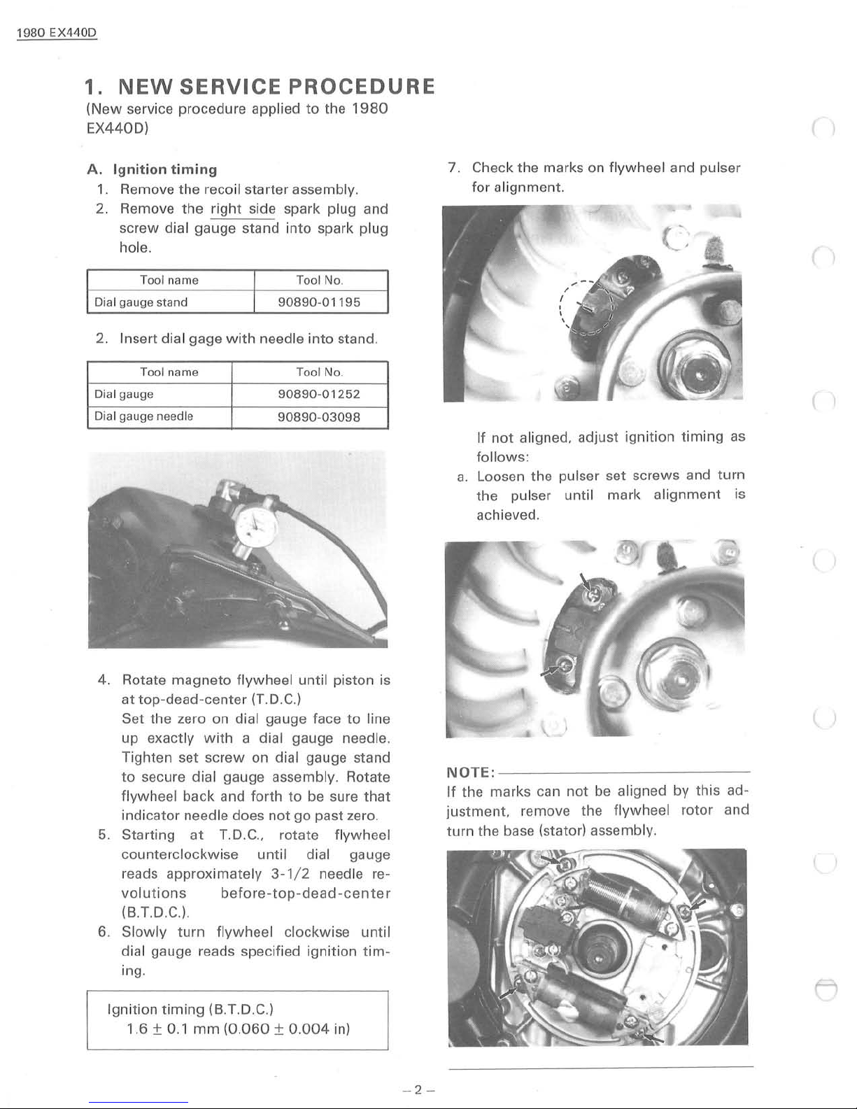
1.
(New
EX440D)
NEW
service procedure applied
SERVICE
PROCEDURE
to
the
1980
A. Ignition timing
1.
Remove the recoil starter assembly.
2. Remove the ri
screw
hol
Dial gauge stand
2. Insert dial gage w ith needle i
Dial gauge
Dial gauge needle
dial gauge stand i
e.
Tool name Tool No.
Tool name
ght
side spark plug and
90890-0
90890-01252
90890-03098
nto
spark plug
nto
Tool No.
1195
stand .
7. Check the marks on flywheel and pu lser
for a
li
gnment.
If
not aligned, adjust i
follows:
a.
Loosen the pulser set screws and
the pu lser until mark
achieved.
gnit
ion timing as
alignment
turn
( )
is
4. Rotate
at
Set the zero on dial gauge face
up exactly
Tighten set
to
flywhee l back and forth
indicator needle does
5. Start ing
counterclockwise
reads approx imate ly 3-1 / 2 needle
volutions
(B
6.
Slowly
dial gauge reads specifi
ing.
Ignition
1.6
magneto
top
-dead-center (T.D.C.)
secure dial gauge assembly . Rotate
at
.T.D.
C.)
.
turn flywheel
timing
± 0
.1
mm
flywheel
with
a dial gauge needle.
screw
(B.T.D.C.)
on dial gauge stand
T.D.C., rotate flywheel
before-top-dead
(0.060 ± 0.004
unti
to
not
go
unt
il dial gauge
clockwise until
ed
l piston is
to
line
be
sure
that
past zero.
re
-cente
ignition tim-
in)
~,
----
\
--------
not
be
----
--
---
aligned by this ad-
...&. \
NOTE:----
If the marks can
justment.
turn
the base (stator) assembly.
r
remove the flywheel rotor and
l )
-
2-
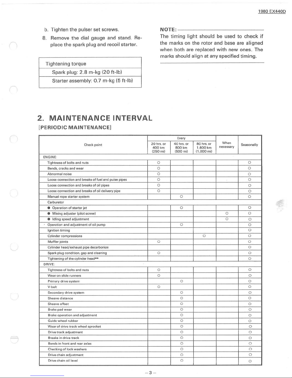
b.
Tight
en
the pulse r set screws.
8. Remove the
dial gauge and stand. Re-
place the spark plug and recoil starter.
Tightening torque
NOTE:
The timing light should
the marks
-------------------------
be used
on
the rotor and base are aligned
when both are replaced with n
marks
should align at any specified
to check if
ew
ones. The
timing
1980 EX440D
.
Spark plug :
Starter assembly:
2.
MAINTENANCE
[
PERIODIC
(
ENGINE:
Tightness of bolts a
8ends. cracks and wear 0
Abnormal noi
Loose connection a
Loose con nection and breaks of oil pip
Loose connection and breaks of oil delivery pipe 0
Manua l rope starter system 0
Carburetor
Operation of starter jet 0
•
Mix
ing adjuster (pil
•
• Idling speed adjustment
Operation and adjustment
Ignition timing
Cylinder compressions
Muffler jo in
Cylinde r head/exhaus t pipe decarboni
Spark plug conditio
Tightening
DRIVE:
Tightness
Wear on slide runners
Pr
V-be lt 0
Secondary dri
Sheave distance
Sheave offset 0
Brake pad
Brake operation and adjustment 0
Guide wheel rubber
Wea r of drive track wheel sprocket 0
Drive track adjustment
Breaks in drive track 0
Be
Che
Drive
Dri
ts
of
of
imary dr ive system 0 0
wear
nds in front and rear axl
cking
of
cha
in adjustment
ve
chain
2.8
m-kg
(20
ft-I
b)
0.7
m-kg (5 ft-Ib)
INTERVAL
MAINTENANCE]
Check point
nd
nuts 0
se
nd
breaks of fuel and pulse pipes
es
ot screw) 0
of
oil pump 0
ze
n.
gap and cleaning 0 0
the cylinder he
bolts and nuts 0
ve
system 0
lock washe
oil
lev
el
ad"
es
rs
20 hrs. or
400
km
(250
mil
0
0
0
0
0 0
Every
40
hrs. or
800
(500m
0 0
0 0
0
0
0
0 0
0
0
km
i) (1
80
hrs. or
1
.600
km
.000m
0 a
i)
When
necessary
0
Seasonally
0
0
0
0
0
0
0
0
0
0
0
0
0
0
0
0
0
0
0
0
0
0
0
0
0
0
0
-3-
1980 EX440D
Every
km 1.
80 hrs.
600
km
(1.000mi)
40
20
Check point
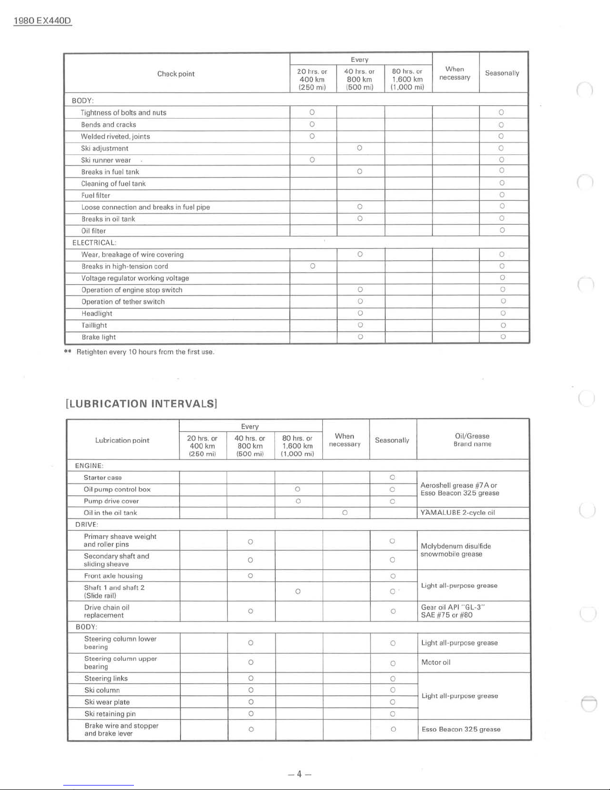
BODY:
Tightness of bolts and nuts 0 0
Bends and cracks
Welded riveted.
Ski
adjustment
Ski
runner wear 0 0
Breaks in fuel tank
Cleaning
Fuel
filter
Loose connection and breaks in fuel pipe
Breaks in oil tank
Oil filter
ELECTRICAL:
Wear. breakage
Breaks in high-tension cord
Vo
ltage regulato r
Operation
Operation of tether switch
Headlight
Taillight
Brake light 0 0
**
Retighten every
joints
of
fuel tank
of
wire
working
of
engine stop switch
10
hours from the first use.
covering
voltage
hrs. or
400
km
(250
mil
0
0 0
0 0
hrs. or
800
(500mi)
0
0
0
0
0
0 0
0
0 0
0
or
When
necessary
Seasonally
0
0
0
0
0
0
0
0
0
0
0
0
(
[LUBRICATION
Lubrication
ENGINE:
Starter
case 0
Oi
l pump control
Pump drive cover
Oi
l in the oil tank 0
DRIVE:
Pr
imary sheave
and roller pins
Secondary shaft and
sliding sheave
axle housing 0
Front
Shaft 1 and
(Slide rail)
ve
chain oil
Dri
replacement
BODY:
Steering column
bearing
Steering column upper
bearing
Steering links
Ski column 0 0
Ski wear plate 0
Ski
retaini ng pin
Brake wire and stopper
and brake
lever
INTERVALS]
point
box
weight
sha
ft 2
lower
20
400
(250
hrs. or
km
mil
Every
40
hrs. or
800
(500mi)
0
0
0
0
0
0
0
0
km
80
1.600
(1.0
hrs. or
km
00m
0
0
0
When
necessary Brand name
i)
Seasonally
0
0
0
0
0
O·
0
0
0
0
0
0
0
O
il/
Grease
Aeroshell grease #7 A or
Esso
Beacon
325
grease
YAMALUBE 2-cycle oil
Mo
lybdenum disulfide
snowmobile grease
Light all-purpose grease
Gear oil API "
SAE
Light all-purpose grease
Motor
Light all-p urpose grease
Esso
#75
or
oil
Beacon
GL-3"
#80
325
grease
l
-4-
 Loading...