


User’s Manual
ENGLISH
E
Ethernet
YAMAHA NETWORK BOARD
IM Operations
882 Soude, Naka-ku, Hamamatsu, Shizuoka 435-0054.Japan
URL http://www.yamaha-motor.jp/robot/index.html
YAMAHA MOTOR CO., LTD.
RCX series
E94-Ver. 1.06


INTRODUCTION
Our thanks for your purchase of this Ethernet unit for use with YAMAHA RCX series robot controllers.
This is an optional unit to allow connecting YAMAHA RCX series robot controllers to the widely
used Ethernet which is a de facto standard for office equipment network.
This manual describes typical examples for taking safety measures, installing wiring, making machine settings and operating the machine to ensure that the Ethernet unit is used safely and effectively. Be sure to read this manual before use. Even after reading this manual, keep it in a safe, easily
accessible location so it can be referred to whenever needed. When moving this unit, always make
sure this manual accompanies it, and make sure that the person who will actually use this Ethernet
unit reads this manual thoroughly.
This manual only contains information involving the Ethernet unit. Please refer to the controller
user's manual and programming manual for information on basic robot controller operation and
programming.
NOTE
• The contents of this manual may be changed in advance without prior notice.
• Every effort was made to ensure the contents of this manual are complete,
however please contact us if errors, ambiguities or possible trouble points are
found.
• This manual does not constitute a warranty of industrial rights or other rights nor
a concession of utility rights. Further, no responsibility whatsoever is accepted for
problems arising from use of the information contents listed in this manual.

MEMO

i
General Contents
Chapter 1 Cautions To Ensure Safety ........................................................................... 1
1-1 Basic safety points ...................................................................................................... 2
1-2 System design safety points ........................................................................................ 2
1-3 Installation and wiring safety points ........................................................................... 3
1-4 Start-up and maintenance safety points ...................................................................... 4
1-5 Precautions when disposing of the unit ...................................................................... 4
1-6 Warranty .................................................................................................................... 4
Chapter 2 Ethernet Unit .............................................................................................. 5
2-1 Ethernet unit features ................................................................................................. 6
2-2 How data is exchanged............................................................................................... 7
2-3 How to connect to Ethernet ....................................................................................... 8
2-4 Making system settings for the controller (server) ...................................................... 9
2-4-1 Validating the Ethernet unit .......................................................................................... 9
2-4-2 Setting the IP address ................................................................................................. 10
2-4-3 Setting the subnet mask .............................................................................................. 12
2-4-4 Setting the gateway .................................................................................................... 13
2-4-5 Setting the communication mode ............................................................................... 14
2-5 Making the PC settings (client) ................................................................................. 15
2-5-1 Setting the TCP/IP protocol......................................................................................... 15
2-6 Checking the connection with "ping" ........................................................................ 17
2-7 Using TELNET ...........................................................................................................18
2-7-1 Difference between TELNET and RS-232C communications....................................... 18
2-8 TELNET dedicated parameters .................................................................................. 19
2-8-1 Parameter description ................................................................................................. 19
2-8-2 Setting the parameters ................................................................................................ 22
2-9 TELENET communication commands........................................................................ 23
2-9-1 Communication command specifications .................................................................. 23
2-9-2 Ethernet unit control commands ................................................................................ 24
2-9-3 Robot control commands ........................................................................................... 24
2-10 Making a connection with TELNET.EXE ..................................................................... 25
2-11 Other operating tasks ............................................................................................... 27
2-11-1 Displaying the MAC address ...................................................................................... 27
2-11-2 Displaying the version of the Ethernet unit ................................................................. 28
2-12 Message List.............................................................................................................. 29
2-12-1 Error messages ........................................................................................................... 29
2-12-2 Telnet message list ..................................................................................................... 30
2-13 Troubleshooting ........................................................................................................ 31
2-14 Specifications ........................................................................................................... 34
2-14-1 Ethernet unit specifications ........................................................................................ 34
2-14-2 Modular connector .................................................................................................... 35
2-14-3 UTP (STP) cable ......................................................................................................... 36
2-15 Supplement............................................................................................................... 37
2-15-1 Typical network systems............................................................................................. 37
2-15-2 Description of terminology ........................................................................................ 41

ii
MEMO

1
1
Cautions To Ensure Safety
Chapter 1 Cautions To Ensure Safety

2
1
Cautions To Ensure Safety
1-1 Basic safety points
Besides reading this manual and the controller user's manual, also be sure to handle the equipment
correctly while paying sufficient attention to safety.
Points regarding safety in this manual only list items involving this product. Please refer to the controller
user's manual for information regarding safety when using this unit with the controller.
It is not possible to detail all safety items within the limited space of this manual. So it is essential that
the user have a full knowledge of basic safety rules and also that the operator makes correct judgments on safety procedures during operation.
Industrial robots are highly programmable, mechanical devices that provide a large degree of freedom when performing various manipulative tasks. Failure to take necessary safety measures or mishandling due to not following the instruction in this manual may result in trouble or damage to the
robot and injury to personnel (robot operator or service personnel) including fatal accidents.
Important caution points in this manual are from hereon indicated by the term:
c
CAUTION
1-2 System design safety points
c
CAUTION
Ethernet communications protocol specifications do not guarantee real-time operation. So relying only on the
Ethernet in situations such as robot emergency stop can be extremely dangerous. Install safety interlock circuits
using the emergency stop terminal in the SAFETY connector of the robot controller to ensure quick and
effective emergency stops.
c
CAUTION
To find the current status of the network system and robot controller when communication errors occur on the
Ethernet system, refer beforehand to this manual and the instruction manual for equipment used by the other
party. Also install safety interlock circuit so that systems including a robot controller will function reliably and
safely when communication errors occur.
c
CAUTION
Do not bundle control lines or communication cables together or in close contact with main circuit or motor/
actuator lines. As a general rule, maintain a gap of at least 100mm. Noise in signal lines may cause faulty
operation.
1-1 Basic safety points

3
1
Cautions To Ensure Safety
1-3 Installation and wiring safety points
c
CAUTION
Always cut off all power to the controller and the overall system before attempting installation or wiring jobs.
This will prevent possible electrical shocks.
After the controller has been on for a while, some points in the controller may be extremely hot or remain at
high voltages. After cutting off the power when installing or removing the unit, wait at least 5 minutes before
starting work.
c
CAUTION
Always uses the system specifications as listed in the controller user's manual during installation or wiring work
on the robot controller. Attempting to use other than these system specifications might cause electrical shocks,
fire, faulty operation, product damage or deteriorated performance.
c
CAUTION
Securely install the connectors into the unit, and when wiring the connectors, make the crimp, contact or solder
connections correctly, using the tool specified by the manufacturer. Poor connections will cause faulty operation.
c
CAUTION
When installing the unit, be careful not to directly touch any electronic components (except DIP switches) or
parts conducting electrical current.
c
CAUTION
Make sure that foreign matter such as wiring debris or dust does not penetrate into the robot controller.
c
CAUTION
Always store network cable inside cable ducts or clamp them securely in place. Otherwise, excessive play or
movement, or mistakenly pulling on the cable may damage the unit or cables, or poor cable contact may lead to
faulty operation.
c
CAUTION
When detaching the cable, remove by holding the connector itself and not by tugging on the cable. Otherwise,
removing by pulling on the cable itself may damage the unit or cables, or poor cable contact may lead to faulty
operation.
1-3 Installation and wiring safety points
4
1
Cautions To Ensure Safety
1-4 Start-up and maintenance safety points
c
CAUTION
Never attempt to disassemble the robot or controller. When a robot or controller component must be repaired or
replaced, contact us for details on how to perform the servicing.
c
CAUTION
Always cut off all power to the controller and the overall system before attempting maintenance or servicing.
This will prevent possible electrical shocks.
After the controller has been on for a while, some points in the controller may be extremely hot or remain at
high voltages. After cutting off the power when installing or removing the unit, wait at least 5 minutes before
starting work.
c
CAUTION
Do not touch the terminals (or pins) while power is still applied to the unit. This may cause electrical shocks or
faulty operation.
1-5 Precautions when disposing of the unit
c
CAUTION
This product must be properly handled as industrial waste when its disposal is required.
1-6 Warranty
For information on the product warranty, please contact your local agent where you purchased your
product.
1-4 Start-up and maintenance safety points

5
2
Ethernet Unit
Chapter 2 Ethernet Unit

6
2
Ethernet Unit
2-1 Ethernet unit features
Ethernet is the network most commonly used by office equipment today. This Ethernet unit is an
optional device for connecting to YAMAHA robot controllers over the Ethernet.
The communications protocol utilizes TCP/IP which is a standard Internet protocol so PCs and business computers with Internet access or equipment incorporating TCP/IP protocols can easily exchange data with the robot controller.
Main features of this Ethernet unit for RCX series robot controllers are as follows:
■ The RCX series robot controllers can be connected to the Ethernet system using this unit. The
unit fits directly inside the controller and so does not require any extra installation space.
■ The Ethernet unit uses 10BASE-T specifications, so UTP cables (unshielded twisted-pair cables)
or STP cables (shielded twisted-pair cables) can be used. This makes cable and wiring installation really easy.
■ Several controllers can be connected on the same network so information can be processed in
one batch from a designated PC.
■ Utilizing a HUB having 10BASE-2 or 10BASE-5 connectors, robot controllers can be accessed even from offices located away from the factory. Using the Internet allows accessing
even robot controllers in remote locations.
■ The robot controller operates as a TELNET (socket) server, which can easily be accessed from
PCs used as TELNET terminals. (For details on how to install TELNET into PCs, see the
relevant instruction manual.)
Ethernet unit commands are the same as those handled through RS-232C, so even first-time
users will find it easy to use.
If information such as network settings on the PC or for detailed information on other equipment is
needed, refer to that particular user's manual or product instruction manual.
For information on operating the YAMAHA robot controller and robot programming, refer to the
controller user's manual and programming manual.
* Ethernet is a registered trademark of the Xerox Corporation (USA).
2-1 Ethernet unit features
7
2
Ethernet Unit
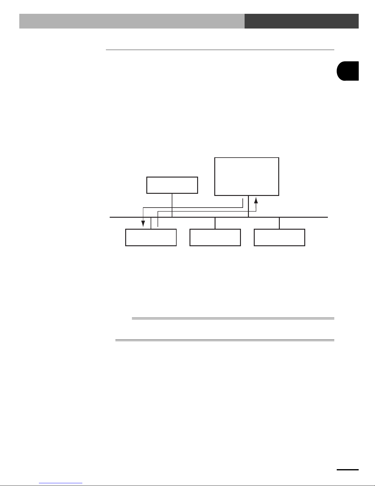
2-2 How data is exchanged
The following is a brief explanation to help understand how information is exchanged over the Ethernet
with the other devices, such as between the robot controller and PC.
In the communications method called TCP/IP, an IP address is assigned to each device connected on
the network. The IP address is a number unique to each device and serves to identify that device. In
the communications process, the IP address of the robot controller must first be specified to make
connection. After making the connection, the actual data is exchanged between the devices and when
finished the connection is terminated.
The RCX series robot controllers equipped with the Ethernet unit operate as a server and constantly
await a connection request from the client (other party's device such as a PC). Specific actions are
then carried out when a request arrives from a client. So the robot controller does not connect to
another server on its own.
Server
Client Client Client
IP address
192.168.0.3
192.168.0.5
192.168.0.10 192.168.0.11
192.168.0.12
RCX series
robot controller
+
Ethernet Unit
q
w
Functions as a server.
Performs specified
actions upon receiving
request from client.
Device such as PC is the client, connects to server and issues commands to perform
specified actions.
Ethernet
q Specify the IP address of robot controller to exchange data with and make the connection.
(Above example shows the client 192.168.0.10 has specified the robot controller 192.168.0.5
and made a connection.)
w After making the connection, the robot controller runs a specific series of actions according to
instructions from the client.
n
NOTE
During multitasking by the client, several robots can be simultaneously connected to one client unit.
Only one client can make a simultaneous connection to one robot controller unit.
Settings such as the IP address and subnet are made from the programming box.
2-2 How data is exchanged
8
2
Ethernet Unit
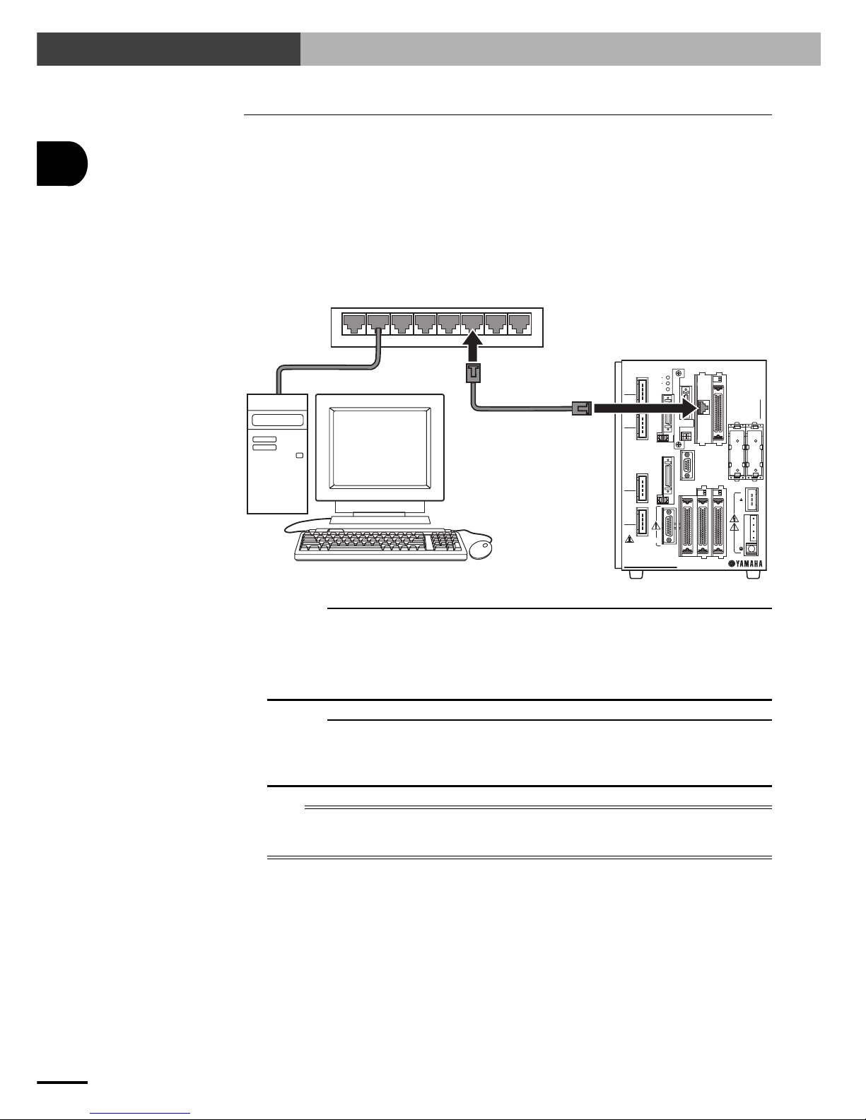
2-3 How to connect to Ethernet
The Ethernet unit for RCX series employs 10BASE-T specifications, so the robot controller connects
by a cable to the HUB.
Use UTP cables (unshielded twisted-pair cables) or STP cables (shielded twisted-pair cables) for
category 3 or higher, with straight-through wiring specifications.
To connect to the Ethernet, insert the cable with modular jack into the modular connector on the
controller until you hear a click. Insert the other end of the cable into the modular connector on the
HUB.
Fig. 2-1 Connecting to Ethernet
RCX series controller
RPB
MOTOR
XM
YM
ZM
RM
PWR
SRV
SAFETY
RPB
COM
STD.DIO
ROB
I/O
ZR
OP.1 OP.3
OP.2 OP.4
RGEN
ACIN
N
P
N1
L1
L
N
SEL
BATT
ZR
XY
BATT
ROB
XY
I/O
PIN13−14
EXT.E-STOP
ERR
RCX240
12345678
HUB
UTP (STP)
straight-through cable
c
CAUTION
We use an FL HUB (made by Phoenix Contact) to check operation. Using this HUB is recommended if
constructing your own system.
HUBs generally available on the market are not designed for use in locations such as factories, so some HUBs
are vulnerable to external noise. Please acknowledge beforehand that operation cannot be guaranteed if other
types of HUBs are used.
Always be sure to use a HUB with high noise resistance when connecting to the controller.
c
CAUTION
The maximum cable length between the HUB and controller is 100 meters.
Before connecting the HUB and controller always refer to the instruction manuals for the device used by the
other party and peripheral equipment such as the HUB.
If the HUB communication mode can be set manually, then set to 10Mbps/Half Duplex.
n
NOTE
Using a straight-through cable is recommended when connecting to the other party's device by way of the HUB.
You can connect directly to the other party's device without the HUB by using a crossover cable but communication
may sometimes not be possible due to the type of LAN adapter used by other party's device.
2-3 How to connect to Ethernet
9
2
Ethernet Unit
2-4 Making system settings for the controller (server)
2-4 Making system settings for the controller (server)
A minimum of IP address, subnet mask and gateway settings must be made so that the robot controller will be correctly identified and acknowledged on Ethernet.
These settings are made from the programming box.
The settings will be enabled after restarting the controller.
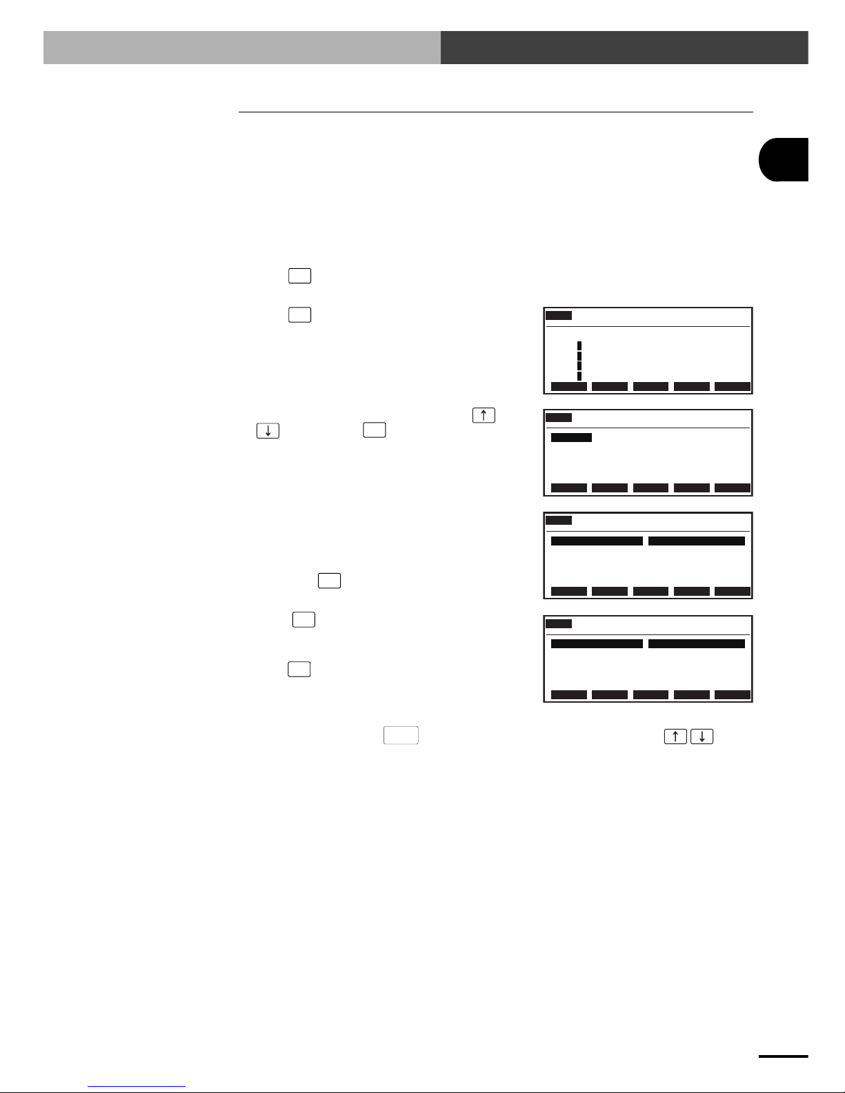
2-4-1 Validating the Ethernet unit
To use the Ethernet, the Ethernet board must first be enabled by setting the parameter.
1) Press F1 (PARAM) in "SYSTEM" mode to enter "SYSTEM>PARAM" mode.
2) Press F5 (OP. BRD).
SYSTM>PARAM V8.01
Robot = YK250X
M1=aYK250X M5= no axis
M2=aYK250X M6= no axis
M3=aYK250X
M4=aYK250X
ROBOT AXIS OTHERS OP.BRD
3) Select the number for "E_Net" with the
keys and press F1 (SELECT).
SYSTM>PARAM>OP.BRD V8.01
1.E_Net
2. ーーー
3. ーーー
4. ーーー
SELECT
SYSTM>PARAM>OP.BRD V8.01
1.board condition VALID
2.IP address 192.168. 0. 2
3.subnet mask 255.255.255. 0
4.gateway 192.168. 0. 1
5.port No 23
EDIT JUMP
4) The current Ethernet unit identity status appears
on the display.
With the cursor positioned on the "1. board
condition" ("1. board function" for RCX221/
222), press F1 (EDIT).
5) Press F2 (VALID) to make the Ethernet
identifiable from the controller.
If making it unidentified from the controller,
press F1 (INVALID).
SYSTM>PARAM>OP.BRD V8.01
1.board condition VALID
2.IP address 192.168. 0. 2
3.subnet mask 255.255.255. 0
4.gateway 192.168. 0. 1
5.port No 23
INVALID VALID
6) To end the setting, press
ESC
. To continue setting another parameter, use the keys to
select the parameter.
 Loading...