

Yamaha EMX512SC User Manual

POWERED MIXER
POWERED MIXER
Owner’s Manual
Owner’s Manual
Quick Guide
Pages 6 to 12
Making the Most of Your Mixer
Pages 13 to 19
EN
CAUTION
RISK OF ELECTRIC SHOCK
DO NOT OPEN
CAUTION: TO REDUCE THE RISK OF
ELECTRIC SHOCK, DO NOT REMOVE
COVER (OR BACK). NO USER-SERVICEABLE
PARTS INSIDE. REFER SERVICING TO
QUALIFIED SERVICE PERSONNEL.
The above warning is located on the rear of the unit.
IMPORTANT SAFETY INSTRUCTIONS
Explanation of Graphical Symbols
The lightning flash with arrowhead symbol
within an equilateral triangle is intended to alert
the user to the presence of uninsulated
“dangerous voltage” within the product’s
enclosure that may be of sufficient magnitude to
constitute a risk of electric shock to persons.
The exclamation point within an equilateral
triangle is intended to alert the user to the
presence of important operating and
maintenance (servicing) instructions in the
literature accompanying the product.
1 Read these instructions.
2Keep these instructions.
3 Heed all warnings.
4 Follow all instructions.
5 Do not use this apparatus near water.
6 Clean only with dry cloth.
7 Do not block any ventilation openings. Install in
accordance with the manufacturer’s instructions.
8 Do not install near any heat sources such as radiators,
heat registers, stoves, or other apparatus (including
amplifiers) that produce heat.
9 Do not defeat the safety purpose of the polarized or
grounding-type plug. A polarized plug has two blades
with one wider than the other. A grounding type plug
has two blades and a third grounding prong. The wide
blade or the third prong are provided for your safety. If
the provided plug does not fit into your outlet, consult
an electrician for replacement of the obsolete outlet.
10 Protect the power cord from being walked on or pinched
particularly at plugs, convenience receptacles, and the
point where they exit from the apparatus.
WARNING
TO REDUCE THE RISK OF FIRE OR ELECTRIC SHOCK, DO NOT EXPOSE THIS APPARATUS TO RAIN OR MOISTURE.
IMPORTANT
Please record the serial number of this unit in the space below.
11 Only use attachments/accessories specified by the
manufacturer.
12 Use only with the cart, stand,
tripod, bracket, or table specified
by the manufacturer, or sold with
the apparatus. When a cart is
used, use caution when moving
the cart/apparatus combination
to avoid injury from tip-over.
13 Unplug this apparatus during
lightning storms or when unused for long periods of
time.
14 Refer all servicing to qualified service personnel.
Servicing is required when the apparatus has been
damaged in any way, such as power-supply cord or plug
is damaged, liquid has been spilled or objects have
fallen into the apparatus, the apparatus has been
exposed to rain or moisture, does not operate normally,
or has been dropped.
(98-6500)
Model:
Serial No.:
The serial number is located on the bottom or rear of the unit.
Retain this Owner’s Manual in a safe place for future reference.
2
EMX512SC/EMX312SC/EMX212S

PRECAUTIONS
PLEASE READ CAREFULLY BEFORE PROCEEDING
* Please keep this manual in a safe place for future reference.
WARNING
Always follow the basic precautions listed below to avoid the possibility of serious injury or even death from electrical
shock, short-circuiting, damages, fire or other hazards. These precautions include, but are not limited to, the following:
Power supply/Power cord
• Only use the voltage specified as correct for the device. The required voltage is
printed on the name plate of the device.
• Use only the included power cord.
• Do not place the power cord near heat sources such as heaters or radiators, and do
not excessively bend or otherwise damage the cord, place heavy objects on it, or
place it in a position where anyone could walk on, trip over, or roll anything over it.
• Be sure to connect to an appropriate outlet with a protective grounding
connection. Improper grounding can result in electrical shock.
Do not open
• Do not open the device or attempt to disassemble the internal parts or modify
them in any way. The device contains no user-serviceable parts. If it should
appear to be malfunctioning, discontinue use immediately and have it inspected
by qualified Yamaha service personnel.
Water warning
• Do not expose the device to rain, use it near water or in damp or wet conditions,
or place containers on it containing liquids which might spill into any openings.
• Never insert or remove an electric plug with wet hands.
If you notice any abnormality
• If the power cord or plug becomes frayed or damaged, or if there is a sudden
loss of sound during use of the device, or if any unusual smells or smoke
should appear to be caused by it, immediately turn off the power switch,
disconnect the electric plug from the outlet, and have the device inspected by
qualified Yamaha service personnel.
• If this device should be dropped or damaged, immediately turn off the power
switch, disconnect the electric plug from the outlet, and have the device
inspected by qualified Yamaha service personnel.
CAUTION
Always follow the basic precautions listed below to avoid the possibility of physical injury to you or others, or damage
to the device or other property. These precautions include, but are not limited to, the following:
Power supply/Power cord
• Remove the electric plug from the outlet when the device is not to be used for
extended periods of time, or during electrical storms.
• When removing the electric plug from the device or an outlet, always hold the
plug itself and not the cord. Pulling by the cord can damage it.
Location
• Before moving the device, remove all connected cables.
• When setting up the device, make sure that the AC outlet you are using is easily
accessible. If some trouble or malfunction occurs, immediately turn off the
power switch and disconnect the plug from the outlet.
• If this device is to be mounted in an EIA-standard rack, leave the back of the rack
open and make sure that it is at least 10 cm away from walls or surfaces. Also, if
this device is to be mounted with devices that tend to generate heat, such as
power amplifiers, be sure to keep an adequate gap between this device and the
heat-generating devices or install ventilation panels to prevent high
temperatures from developing inside this device.
Inadequate ventilation can result in overheating, possibly causing damage to the
device(s), or even fire.
• Do not use the device in a confined, poorly-ventilated location. If this device is to
be used in a small space other than an EIA-standard rack, make sure that there is
adequate space between the device and surrounding walls or other devices: at
least 10 cm at the sides, 25 cm behind and 15 cm above. Inadequate ventilation
can result in overheating, possibly causing damage to the device(s), or even fire.
•Avoid setting all equalizer controls and faders to their maximum. Depending on
the condition of the connected devices, doing so may cause feedback and may
damage the speakers.
• Do not expose the device to excessive dust or vibrations, or extreme cold or heat
(such as in direct sunlight, near a heater, or in a car during the day) to prevent
the possibility of panel disfiguration or damage to the internal components.
• Do not place the device in an unstable position where it might accidentally fall over.
• Do not block the vents. This device has ventilation holes at the rear and side to
prevent the internal temperature from becoming too high. In particular, do not
place the device on its side or upside down. Inadequate ventilation can result in
overheating, possibly causing damage to the device(s), or even fire.
• Do not use the device in the vicinity of a TV, radio, stereo equipment, mobile
phone, or other electric devices. Doing so may result in noise, both in the device
itself and in the TV or radio next to it.
Connections
• Before connecting the device to other devices, turn off the power for all devices.
Before turning the power on or off for all devices, set all volume levels to minimum.
• Use only speaker cables for connecting speakers to the speaker jacks. Use of
other types of cables may result in fire.
Handling caution
• When turning on the AC power in your audio system, always turn on the device
or external power amplifiers LAST, to avoid speaker damage. When turning the
power off, the device or external power amplifiers should be turned off FIRST for
the same reason.
• Do not insert your fingers or hands in any gaps or openings on the device
(vents, etc.).
•Avoid inserting or dropping foreign objects (paper, plastic, metal, etc.) into any
gaps or openings on the device (vents, etc.) If this happens, turn off the power
immediately and unplug the power cord from the AC outlet. Then have the
device inspected by qualified Yamaha service personnel.
• Do not use the device for a long period of time at a high or uncomfortable
volume level, since this can cause permanent hearing loss. If you experience
any hearing loss or ringing in the ears, consult a physician.
• Do not rest your weight on the device or place heavy objects on it, and avoid use
excessive force on the buttons, switches or connectors.
(5)-4 2/3
EMX512SC/EMX312SC/EMX212S
3
XLR-type connectors are wired as follows (IEC60268 standard): pin 1: ground, pin 2: hot (+), and pin 3: cold (-).
Use only Neutrik plugs (NL4) for connecting Speakon connectors.
Yamaha cannot be held responsible for damage caused by improper use or modifications to the device.
Always turn the power off when the device is not in use.
The performance of components with moving contacts, such as switches, volume controls, and connectors, deteriorates over time. Consult qualified Yamaha service
personnel about replacing defective components.
IMPORTANT NOTICE FOR THE UNITED KINGDOM
Connecting the Plug and Cord
WARNING: THIS APPARATUS MUST BE EARTHED
IMPORTANT. The wires in this mains lead are coloured in accordance with the following code:
As the colours of the wires in the mains lead of this apparatus may not correspond with the coloured markings identifying the terminals in your plug proceed as follows:
The wire which is coloured GREEN-and-YELLOW must be connected to the terminal in the plug which is marked by the letter E or by
the safety earth symbol or coloured GREEN or GREEN-and-YELLOW.
The wire which is coloured BLUE must be connected to the terminal which is marked with the letter N or coloured BLACK.
The wire which is coloured BROWN must be connected to the terminal which is marked with the letter L or coloured RED.
• This applies only to products distributed by Yamaha-Kemble Music (U.K.) Ltd. (3 wires)
GREEN-AND-YELLOW : EARTH
BLUE : NEUTRAL
BROWN : LIVE
FCC INFORMATION (U.S.A.)
1. IMPORTANT NOTICE: DO NOT MODIFY THIS UNIT!
This product, when installed as indicated in the instructions contained in this manual, meets FCC requirements. Modifications not
expressly approved by Yamaha may void your authority, granted by
the FCC, to use the product.
2. IMPORTANT: When connecting this product to accessories and/
or another product use only high quality shielded cables. Cable/s
supplied with this product MUST be used. Follow all installation
instructions. Failure to follow instructions could void your FCC
authorization to use this product in the USA.
3. NOTE: This product has been tested and found to comply with the
requirements listed in FCC Regulations, Part 15 for Class “B” digital devices. Compliance with these requirements provides a reasonable level of assurance that your use of this product in a
residential environment will not result in harmful interference with
other electronic devices. This equipment generates/uses radio frequencies and, if not installed and used according to the instructions found in the users manual, may cause interference harmful to
the operation of other electronic devices. Compliance with FCC
regulations does not guarantee that interference will not occur in all
installations. If this product is found to be the source of interference, which can be determined by turning the unit “OFF” and “ON”,
please try to eliminate the problem by using one of the following
measures:
Relocate either this product or the device that is being affected by
the interference.
Utilize power outlets that are on different branch (circuit breaker or
fuse) circuits or install AC line filter/s.
In the case of radio or TV interference, relocate/reorient the
antenna. If the antenna lead-in is 300 ohm ribbon lead, change the
lead-in to co-axial type cable.
If these corrective measures do not produce satisfactory results,
please contact the local retailer authorized to distribute this type of
product. If you can not locate the appropriate retailer, please contact Yamaha Corporation of America, Electronic Service Division,
6600 Orangethorpe Ave, Buena Park, CA90620
The above statements apply ONLY to those products distributed by
Yamaha Corporation of America or its subsidiaries.
* This applies only to products distributed by YAMAHA CORPORATION OF AMERICA. (class B)
About this Manual
This manual is divided into two main sections, as follows.
■ Mixer Basics (starts on page 6)
Presents a general explanation of mixers and mixer concepts. Includes a Quick Guide that will help beginners get up to speed very quickly.
■ EMX Setup and Operation (starts on page 20)
Provides detailed information about the EMX. Introduces the EMX features, identifies and explains the controls, indicators, and connectors; and explains how to set up the equipment.
* This manual applies to models EMX512SC, EMX312SC, and EMX212SC. Within this manual, the term “EMX” is used to refer to all three of these models.
* Illustrations herein are for explanatory purposes only, and may not match actual appearance during operation.
* Company names and product names herein are trademarks or registered trademarks of their respective companies.
Copying of commercially available music or other audio data for purposes other than personal use is strictly prohibited by copyright law. Please respect all
copyrights, and consult with a copyright specialist if you are in doubt about permissible use.
4
EMX512SC/EMX312SC/EMX212S

Thank you for your purchase of this Yamaha EMX512SC, EMX312SC, or EMX212S power mixer.
Please read through this manual carefully before beginning use, so that you will be able to take full
advantage of your mixer’s superlative features and enjoy trouble-free operation for years to come. After
reading the manual, please store it in a safe place.
Contents Features
■ Basic
Quick Guide 6
Before Turning On the Mixer........................................ 6
Getting Sound to the Speakers.................................... 7
Adding Some Reverb................................................. 11
Using the Compressors to Enhance Vocals .............. 12
Making the Most of Your Mixer 13
A Place for Everything and Everything in its Place .... 13
A Plethora of Connectors—What Goes Where? ... 13
Balanced, Unbalanced—What’s the Difference? .. 14
Signal Levels and the Decibel.................................... 15
Making Better Mixes................................................... 15
Approaching the Mix—Where Do You Start? ...... 15
To EQ or Not to EQ.............................................. 16
Ambience ............................................................. 17
The Modulation Effects: Phasing, Chorus,
and Flanging ........................................................18
Compression........................................................ 18
■ Reference
Controls and Connectors 20
Controls on Each Channel ......................................... 20
Digital Effects Section ................................................ 22
MAIN Section ............................................................. 23
MONITOR Section ..................................................... 24
POWER Section ........................................................ 25
Rear Panel ................................................................. 26
Connecting Speakers 27
Horizontal Orientation, Tilting and
Rack Mounting 28
Horizontal Orientation ................................................28
Tilting ......................................................................... 29
Rack Mounting ........................................................... 29
Input Channels..................................... page 20
The EMX offers four monoaural mic/line input channels (1
to 4) and four stereo input channel pairs (5/6 to 11/12),
allowing you to freely mix inputs from microphones, linelevel devices, and stereo devices. For example, you can
mix four microphones with four stereo devices, or seven
microphones with one stereo synthesizer.
Phantom Power (+15V)........................page 25
A single switch turns phantom power on to all mic inputs.
Use this feature to provide power to condenser microphones.
High-Quality Digital Effects ................ page 22
The mixer’s internal effector is in the same league as our
SPX effector series, allowing you to create a rich range of
variations with no external help. But of course you are also
free to use the EFFECT OUT jack to connect to an external
effector of your choice.
MAIN and MONITOR Outputs ............. page 23
The mixer offers excellent independent control of main and
monitor output. The top panel offers separate main and
monitor outputs, while the POWER AMP switch can be
used to set the SPEAKERS jacks so that they output either
the main signal to both speakers or else the main signal to
one speaker and the monitor signal to the other. Separate
MASTER control knobs and 7-segment graphic equalizers
are also provided.
Compressors (EMX512SC and
EMX312SC only) .................................. page 21
Compressors on channels 1 to 4 can be used to squeeze
the dynamic range of inputs such as microphones and
acoustic guitars, attenuating the higher levels and bringing
out the lower ones. This feature helps reduce distortion and
allows overall volume to be set higher, resulting in a stronger and more impressive sound.
Tilt Setup or Rack Mount ................... page 29
The EMX can be positioned at an angle or mounted in a
rack, allowing for easy accessibility in a wide variety of setups.
Setting Up 30
Troubleshooting 31
Specifications 32
Internal Power Amp.............................page 25
The internal amp makes it possible to connect the SPEAKERS jacks directly to non-powered speakers, with no need
for an external amplifier in between. The rear panel offers
two types of speaker connectors: phone jacks and Neutrik
Speakon jacks.
EMX512SC/EMX312SC/EMX212S
5
BASIC
Quick Guide
Before Turning On the Mixer
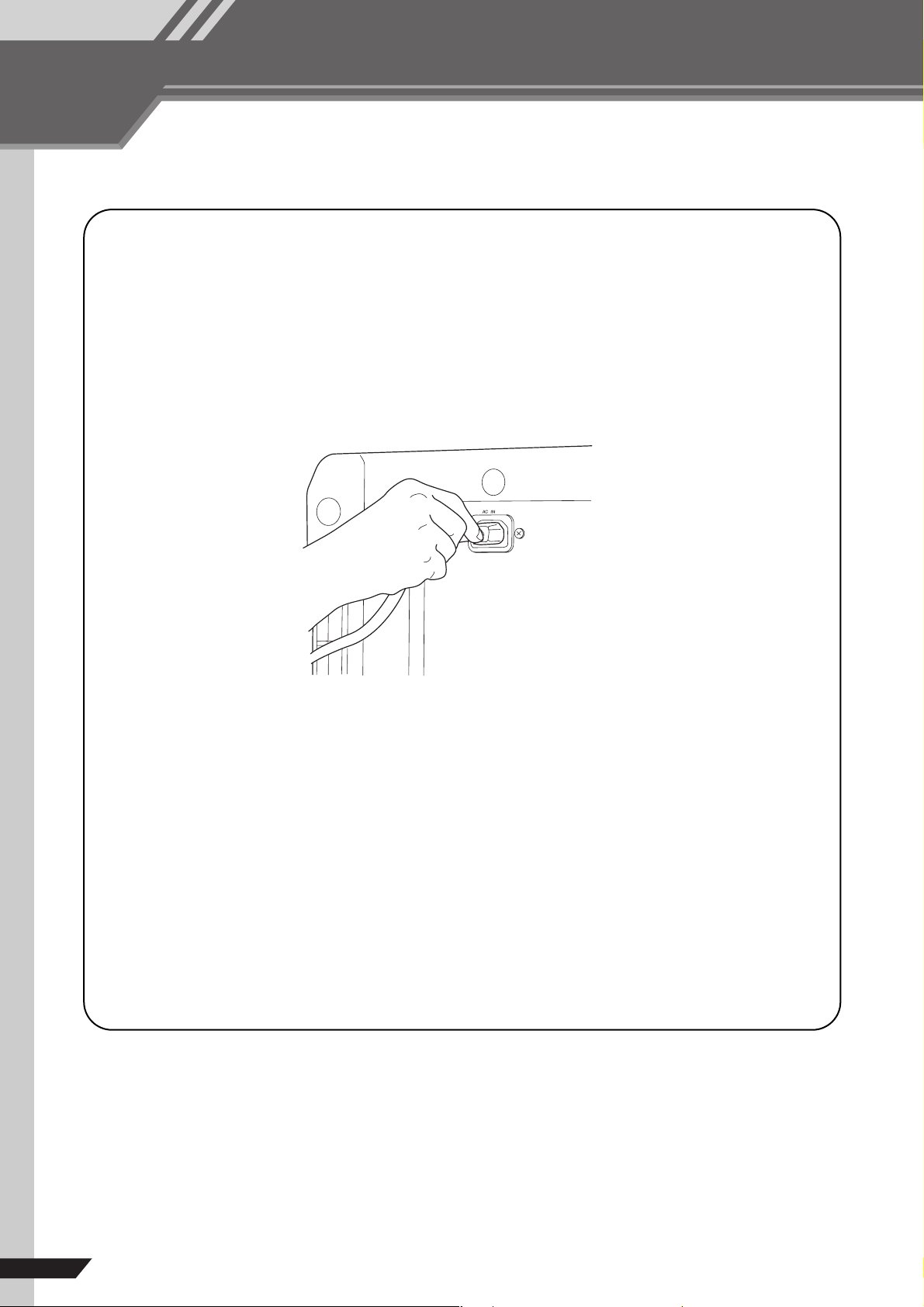
■ Connecting to Power
1 Be sure that the POWER switch is in the OFF position.
2 Connect the included power cord to the AC IN connector on the rear panel.
3 Plug the power cord into a standard power outlet.
■ Turning the Unit On and Off
NOTE
• To prevent an unpleasant burst of noise from the speakers, you should power up the sound sources first, and then the other devices in
order of their distance from the source (starting with the closest).
For example: Sound source (external device)
When turning power off, proceed in the opposite order.
• Before turning power on, make sure that the LEVEL and MASTER knobs are set to the “0” position.
→
EMX unit → Amps (Powered speakers)
1 Push the POWER switch in to turn the power ON.
The power lamp lights up to indicate that power is on. To turn the power off, push the switch again, so that it
pops out.
6
EMX512SC/EMX312SC/EMX212S
Getting Sound to the Speakers
We begin by connecting up two speakers and generating some
stereo output. Note that operations and procedures will vary
somewhat according to the input devices you are using.
BASIC
Quick Guide
5
3
2,8
2,7,9
4
6
1
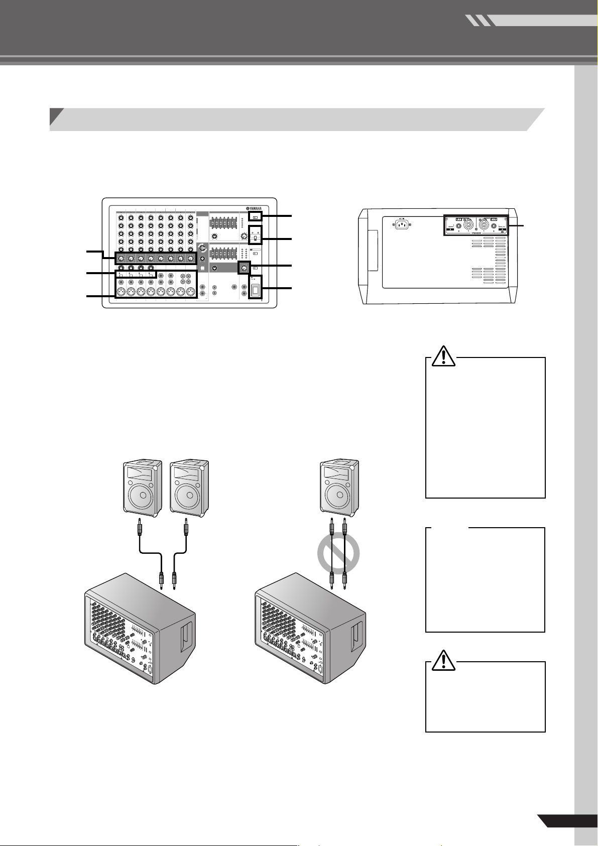
1 Connect up the speakers and your input devices
(microphones, instruments, etc.)
Use non-powered speakers and dedicated speaker cable. Connect one speaker
to SPEAKERS jack A (A1 or A2), and the other to jack B (B1 or B2). Then connect your input devices (microphones, guitar, etc.) to the appropriate input jacks
on the top panel. For details, see page 30.
RIGHT WRONG!!
1
Before connecting input
devices to the EMX, be sure
that all of these devices (including microphones) are powered
off. And before turning the
power to any device on or off,
be sure to turn the volume of
that device all the way down.
Neglect of these precautions
may result in large noise bursts
that may damage your equipment, your ears, or both.
NOTE
We recommend that you do not
connect electric instruments
(such as electric guitars and
basses) directly to the EMX.
Instead, these instruments
should be connected through
an intermediary device such as
a direct box, a preamp (guitar
amp), or an amp simulator.
Never connect both A and B
jacks to a single speaker. Connection of both jacks to the
same speaker may result in
damage to the mixer.
EMX512SC/EMX312SC/EMX212S
7
BASIC
Quick Guide
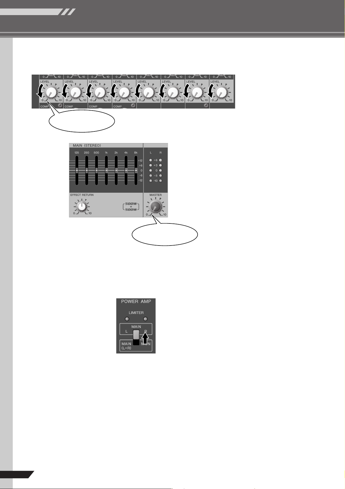
2 Turn the LEVEL knobs and the MASTER knobs to 0.
This position
This position
3 Set the POWER AMP switch to its upper position
(to MAIN L-R).
For information about this switch, see page 25.
8
EMX512SC/EMX312SC/EMX212S
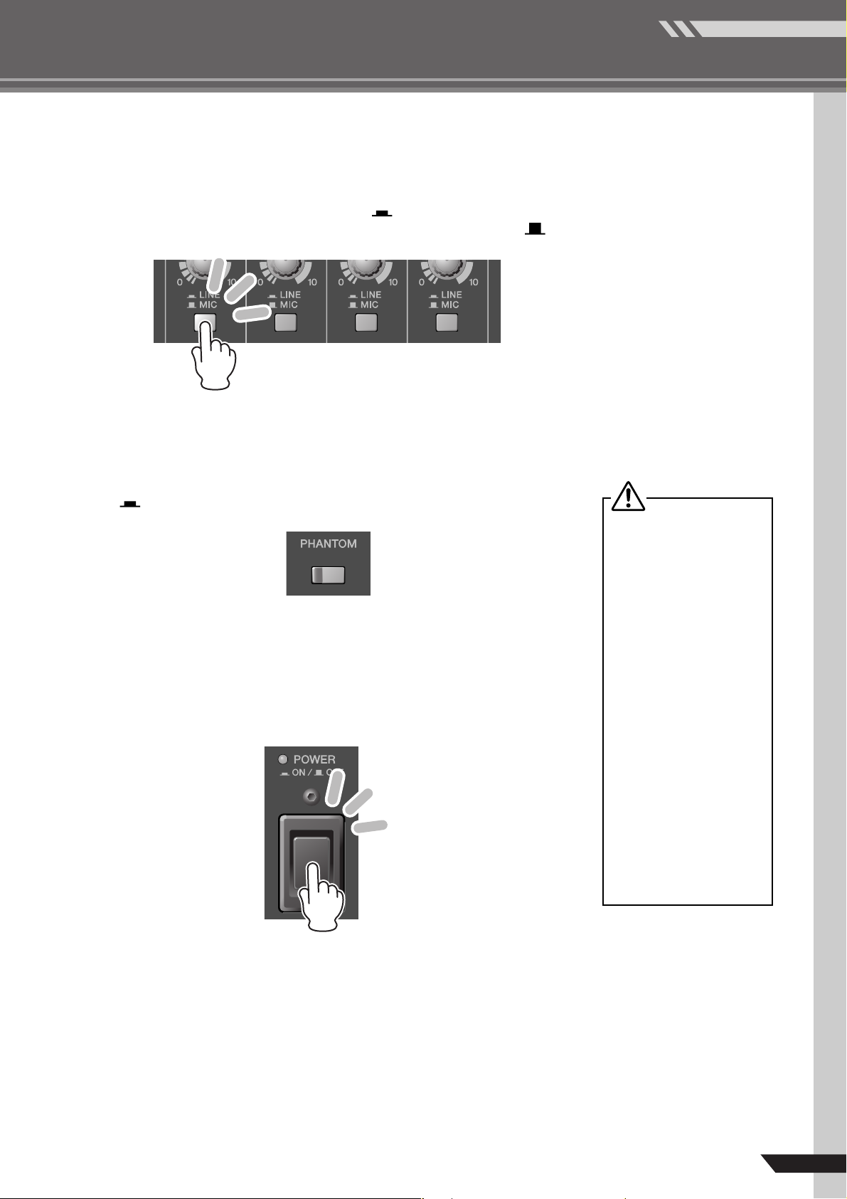
4 If you have connected input devices to channels 1 to 4, set
the LINE/MIC switch on each channel accordingly.
If you have connected a line-level device, such as a keyboard or audio device,
set the channel’s switch to the LINE position ( ). If you have connected a
microphone or other mic-level device, set the switch to the MIC position ( ).
BASIC
Quick Guide
5 If you are using one or more condenser microphones for
your inputs, set the PHANTOM switch to the ON position
().
6 Turn on the power.
First turn on the power to all connected devices other than powered speakers
and amp, and then turn on the EMX itself. If using powered speakers or amps,
turn these on last.
• Be sure to leave this switch
off if you do not need phantom power.
• When using phantom power,
do not connect any devices
other than condenser microphones to the XLR input
jacks. Other devices may be
damaged if connected to
phantom power. This precaution does not apply to balanced dynamic microphones,
however, as these will not be
affected by phantom power.
• Before turning the PHANTOM switch ON or OFF, be
sure to turn off the power to
the mixer and to all other
devices having internal
amplifiers. It is also recommended that you set both
MASTER knobs to their “0”
position. Neglect of these
precautions may result in
damage to speakers, to other
equipment, or to your ears.
EMX512SC/EMX312SC/EMX212S
9
BASIC
Quick Guide
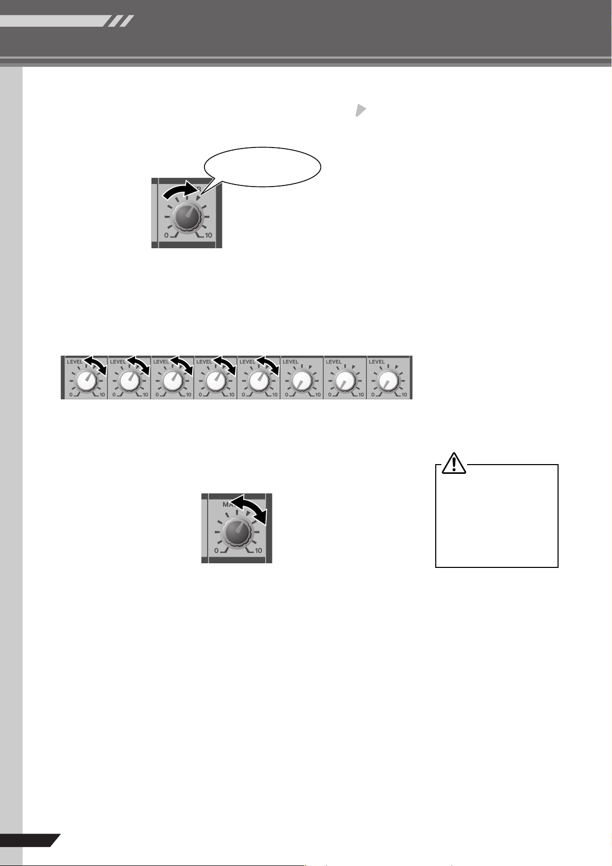
7 Turn the MASTER knob in the MAIN section to the posi-
tion.
This position
8 Adjust the LEVEL knobs for all occupied channels.
For each input device you have connected: Generate sound from the device
while adjusting the corresponding channel’s LEVEL knob. Adjust so that the
LEVEL meter occasionally reaches the “0” level.
9 Now turn the MASTER knob in the MAIN section again
as necessary to adjust the overall output level.
It is acceptable for the LIMITER
lamps to flash on briefly at
times, but if they remain lit continuously then there is risk of
damage to your speakers or to
the internal amp. Reduce the
MASTER knob setting so that
these lamps do not stay on.
10
EMX512SC/EMX312SC/EMX212S
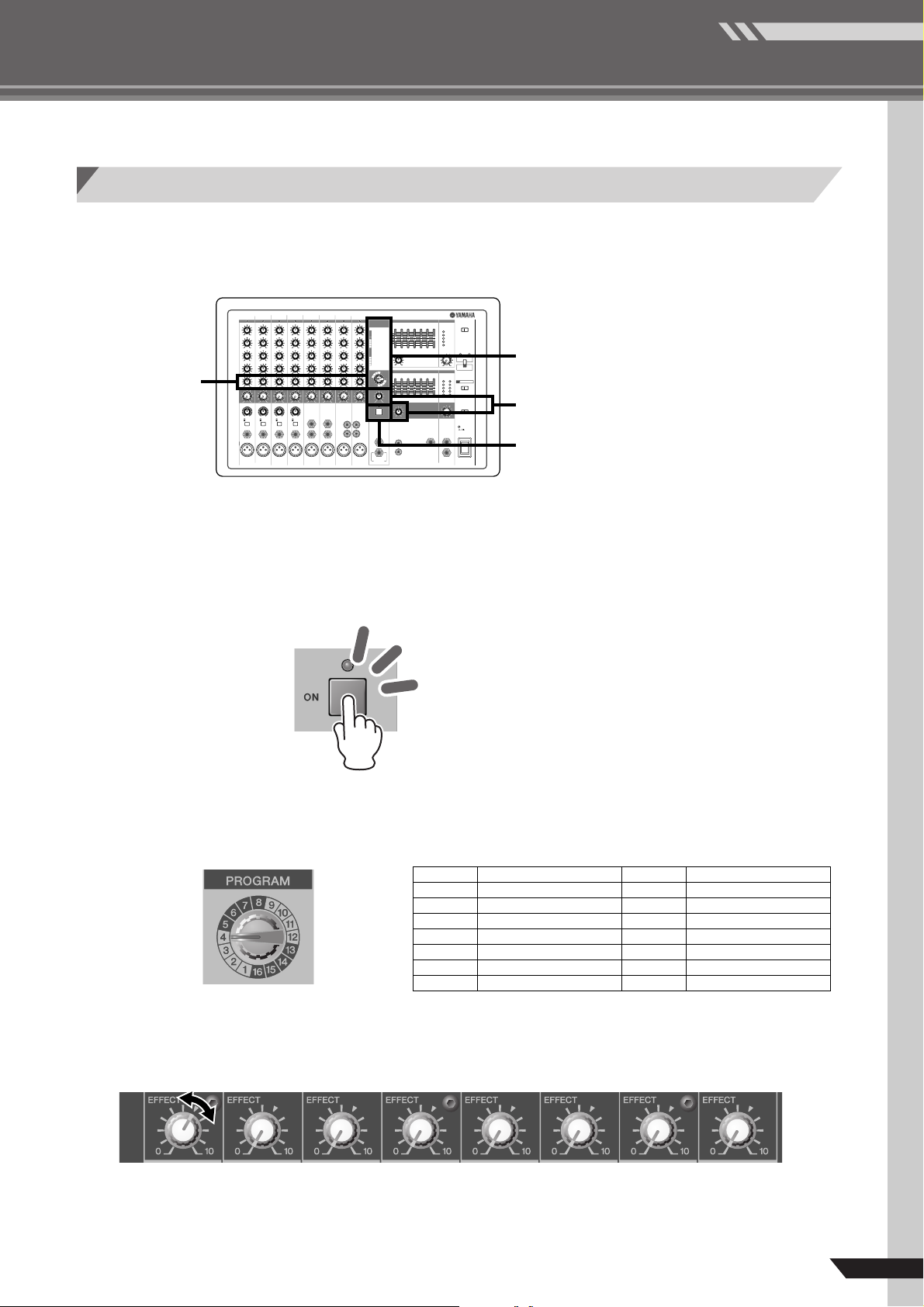
Adding Some Reverb
Now let’s try adding some reverb to your input. The reverb effects
let you simulate the sound of different performance environments—such as concert halls and small clubs.
2
3
4
1
BASIC
Quick Guide
1 Turn the ON switch to it’s ON position.
This switch turns the internal effector on and off. The lamp lights up orange to
indicate that the effector is on. As an alternative to the ON switch, you can use a
separately sold FC5 foot switch to toggle the effector on and off.
2 Turn the PROGRAM dial to select the desired effect type;
To select a reverb effect, turn the dial to any value from 1 to 7.
1
2
3
4
55
55
66
66
77
77
88
88
REVERB HALL 1
REVERB HALL 2
REVERB ROOM 1
REVERB ROOM 2
REVERB STAGE 1
REVERB STAGE 2
REVERB PLATE
DRUM AMBIENCE
9
0
A
B
CC
CC
DD
DD
EE
EE
FF
FF
KARAOKE ECHO
VOCAL ECHO
CHORUS 1
CHORUS 2
FLANGER
PHASER
AUTO WAH
DISTORTION
3 Use the channel EFFECT knobs to adjust the effect
depth for each channel.
EMX512SC/EMX312SC/EMX212S
11
 Loading...