

Yamaha E8D Owner's Manual

OWNER’S MANUAL
E8D
677-28199-20-E0

Read this owner’s manual carefully before operating your outboard motor.
Important manual information
EMU25100
To the owner
Thank you for choosing a Yamaha outboard
motor. This Owner’s Manual contains information needed for proper operation, maintenance and care. A thorough understanding of
these simple instructions will help you obtain
maximum enjoyment from your new Yamaha.
If you have any question about the operation
or maintenance of your outboard motor,
please consult a Yamaha dealer.
In this Owner’s Manual particularly important
information is distinguished in the following
ways.
The Safety Alert Symbol means ATTENTION! BECOME ALERT! YOUR SAFETY IS INVOLVED!
EWM00780
WARNING
Failure to follow WARNING instructions
could result in severe injury or death
machine operator, a bystander, or a person inspecting or repairing the outboard
motor.
ECM00700
CAUTION:
A CAUTION indicates special precautions
that must be taken to avoid damage to the
outboard motor.
to the
your machine and this manual. If there is any
question concerning this manual, please consult your Yamaha dealer.
NOTE:
The E8DMH and the standard accessories
are used as a base for the explanations and
illustrations in this manual. Therefore some
items may not apply to every model.
EMU25120
E8D
OWNER’S MANUAL
©2004 by Yamaha Motor Co., Ltd.
1st Edition, February 2004
All rights reserved.
Any reprinting or unauthorized use
without the written permission of
Yamaha Motor Co., Ltd.
is expressly prohibited.
Printed in Japan
NOTE:
A NOTE provides key information to make
procedures easier or clearer.
Yamaha continually seeks advancements in
product design and quality. Therefore, while
this manual contains the most current product
information available at the time of printing,
there may be minor discrepancies between

Table of contents
General information ......................1
Identification numbers record ...... 1
Outboard motor serial number ....... 1
EC label....................................... 1
Safety information ....................... 1
Important labels........................... 2
Warning labels................................ 2
Fueling instructions ..................... 3
Gasoline ......................................... 3
Engine oil........................................ 3
Propeller selection....................... 3
Start-in-gear protection ............... 4
Basic components ........................ 5
Main components ........................ 5
Fuel tank......................................... 5
Fuel joint......................................... 6
Fuel tank cap.................................. 6
Air vent screw................................. 6
Tiller handle.................................... 6
Gear shift lever............................... 6
Throttle grip .................................... 6
Throttle indicator............................. 6
Throttle friction adjuster.................. 7
Engine stop lanyard switch............. 7
Engine stop button ......................... 8
Choke knob for pull type................. 8
Manual starter handle..................... 8
Steering friction adjuster................. 8
Trim rod (tilt pin) ............................. 8
Tilt lock mechanism........................ 9
Tilt support bar ............................... 9
Top cowling lock lever(s)
(turn type).................................... 9
Operation ..................................... 10
Installation ................................. 10
Mounting the outboard motor ....... 10
Clamping the outboard motor....... 11
Breaking in engine .................... 12
Gasoline and engine oil mixing
chart (25:1)................................ 12
Procedure for pre-mixed
models ...................................... 12
Preoperation checks ................. 13
Fuel .............................................. 13
Oil ................................................. 13
Controls ........................................ 13
Engine .......................................... 13
Filling fuel and engine oil .......... 13
Filling fuel for portable tank .......... 13
Gasoline and oil mixing ................ 13
Operating engine ...................... 14
Feeding fuel (portable tank) ......... 14
Starting engine ............................. 15
Warming up engine................... 17
Choke start models ...................... 17
Shifting ...................................... 18
Forward (tiller handle and
remote control models) ............. 18
Reverse (manual tilt and
hydro tilt models)....................... 18
Stopping engine ........................ 19
Procedure..................................... 19
Trimming outboard motor.......... 19
Adjusting trim angle for
manual tilt models..................... 20
Adjusting boat trim........................ 20
Tilting up and down................... 21
Procedure for tilting up
(manual tilt models)................... 22
Procedure for tilting down
(manual tilt models)................... 23
Cruising in shallow water .......... 23
Cruising in shallow water
(manual tilt models)................... 23
Cruising in other conditions....... 24
Maintenance ................................ 26
Specifications............................ 26
Transporting and storing
outboard motor ...................... 26
Clamp screw mounting models .... 27
Storing outboard motor................. 27
Procedure..................................... 28

Lubrication
(except oil injection models)...... 29
Cleaning the outboard motor........ 29
Checking painted
surface of motor........................ 29
Periodic maintenance................ 29
Replacement parts ....................... 29
Maintenance chart........................ 30
Greasing....................................... 31
Cleaning and adjusting
spark plug ................................. 31
Checking fuel system ................... 32
Inspecting fuel filter ...................... 33
Cleaning fuel filter......................... 33
Inspecting idling speed................. 33
Checking wiring and
connectors ................................ 34
Exhaust leakage........................... 34
Water leakage .............................. 34
Checking propeller ....................... 34
Removing the propeller ................ 35
Installing the Propeller.................. 35
Changing gear oil ......................... 36
Cleaning fuel tank......................... 37
Inspecting and replacing
anode(s).................................... 37
Checking top cowling ................... 38
Coating the boat bottom............... 38
Table of contents
Trouble Recovery ........................ 39
Troubleshooting ........................ 39
Temporary action in
emergency ............................. 42
Impact damage............................. 42
Starter will not operate ................. 42
Emergency starting engine........... 43
Treatment of
submerged motor ................... 44
Procedure..................................... 44
General information
EMU25170
Identification numbers record
EMU25182
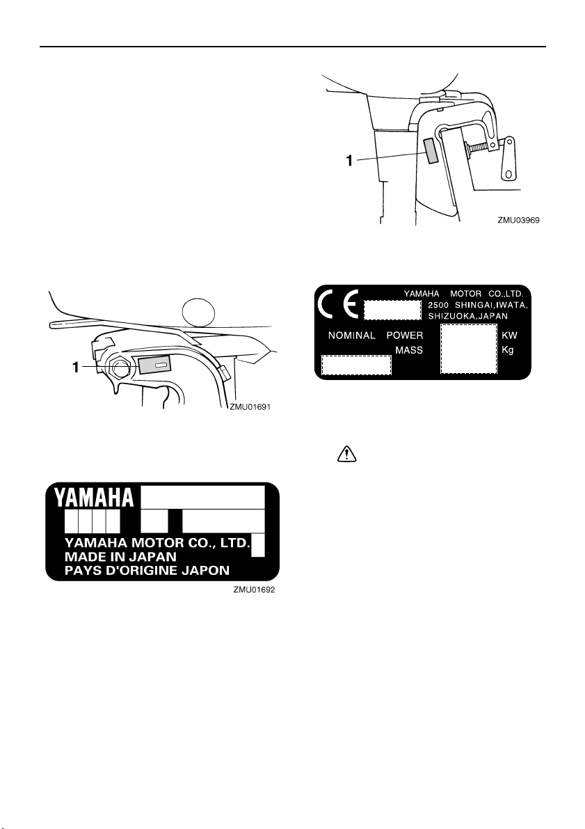
Outboard motor serial number
The outboard motor serial number is stamped
on the label attached to the port side of the
clamp bracket or the upper part of the swivel
bracket.
Record your outboard motor serial number in
the spaces provided to assist you in ordering
spare parts from your Yamaha dealer or for
reference in case your outboard motor is stolen.
1. EC label location
ZMU01696
1. Outboard motor serial number location
EMU25202
EC label
Engines affixed with this label conform to certain portions of the European Parliament directive relating to machinery. Refer to the
label and the EC Declaration of Conformity for
more details.
1
EMU25370
Safety information
● Before mounting or operating the outboard
motor, read this entire manual. Reading it
should give you an understanding of the
motor and its operation.
● Before operating the boat, read any own-
er’s or operator’s manuals supplied with it
and all labels. Be sure you understand each
item before operating.
● Do not overpower the boat with this out-
board motor. Overpowering the boat could
result in loss of control. The rated power of
the outboard should be equal to or less than
the rated horsepower capacity of the boat.
If the rated horsepower capacity of the boat
is unknown, consult the dealer or boat manufacturer.
General information
● Do not modify the outboard. Modifications
could make the motor unfit or unsafe to use.
● Never operate after drinking alcohol or tak-
ing drugs. About 50% of all boating fatalities
involve intoxication.
● Have an approved personal flotation device
(PFD) on board for every occupant. It is a
good idea to wear a PFD whenever boating. At a minimum, children and non-swimmers should always wear PFDs, and
everyone should wear PFDs when there
are potentially hazardous boating conditions.
● Gasoline is highly flammable, and its va-
pors are flammable and explosive. Handle
and store gasoline carefully. Make sure
there are no gas fumes or leaking fuel before starting the engine.
● This product emits exhaust gases which
contain carbon monoxide, a colorless,
odorless gas which may cause brain damage or death when inhaled. Symptoms include nausea, dizziness, and drowsiness.
Keep cockpit and cabin areas well ventilated. Avoid blocking exhaust outlets.
● Check throttle, shift, and steering for proper
operation before starting the engine.
● Attach the engine stop switch lanyard to a
secure place on your clothing, or your arm
or leg while operating. If you accidentally
leave the helm, the lanyard will pull from the
switch, stopping the engine.
● Know the marine laws and regulations
where you will be boating - and obey them.
● Stay informed about the weather. Check
weather forecasts before boating. Avoid
boating in hazardous weather.
● Tell someone where you are going: leave a
Float Plan with a responsible person. Be
sure to cancel the Float Plan when you return.
● Use common sense and good judgment
when boating. Know your abilities, and be
sure you understand how your boat handles under the different boating conditions
you may encounter. Operate within your
limits, and the limits of your boat. Always
operate at safe speeds, and keep a careful
watch for obstacles and other traffic.
● Always watch carefully for swimmers during
the engine operation.
● Stay away from swimming areas.
● When a swimmer is in the water near you
shift into neutral and shut off the engine.
EMU25380
Important labels
EMU25395
Warning labels
EMU25401
Label
EWM01260
WARNING
● Be sure shift control is in neutral before
starting engine. (except 2HP)
● Do not touch or remove electrical parts
when starting or during operation.
● Keep hands, hair, and clothes away from
flywheel and other rotating parts while
engine is running.
2
General information
EMU25431
Label
EWM01300
WARNING
● This engine is equipped with a neutral
starting device.
● The engine will not start unless the shift
control is in neutral position.
EMU25540
Fueling instructions
EWM00010
WARNING
GASOLINE AND ITS VAPORS ARE HIGHLY FLAMMABLE AND EXPLOSIVE!
● Do not smoke when refueling, and keep
away from sparks, flames, or other
sources of ignition.
● Stop engine before refueling.
● Refuel in a well-ventilated area. Refuel
portable fuel tanks off the boat.
● Take care not to spill gasoline. If gaso-
line spills, wipe it up immediately with
dry rags.
● Do not overfill the fuel tank.
● Tighten the filler cap securely after refu-
eling.
● If you should swallow some gasoline, in-
hale a lot of gasoline vapor, or get gasoline in your eyes, get immediate medical
attention.
● If any gasoline spills onto your skin, im-
mediately wash with soap and water.
Change clothing if gasoline spills on it.
● Touch the fuel nozzle to the filler open-
ing or funnel to help prevent electrostatic sparks.
ECM00010
CAUTION:
Use only new clean gasoline which has
been stored in clean containers and is not
contaminated with water or foreign matter.
EMU30330
Gasoline
Recommended gasoline:
Regular unleaded gasoline
If knocking or pinging occurs, use a different
brand of gasoline or premium unleaded fuel. If
unleaded gasoline is not available, then premium gasoline can be used.
EMU25650
Engine oil
Recommended engine oil:
YAMALUBE 2-stroke outboard motor
oil
If the recommended engine oil is not available, another 2-stroke engine oil with an
NMMA-certified TC-W3 rating may be used.
EMU25741
Propeller selection
The performance of your outboard motor will
be critically affected by your choice of propeller, as an incorrect choice could adversely affect performance and could also seriously
damage the motor. Engine speed depends on
the propeller size and boat load. If engine
speed is too high or too low for good engine
performance, this will have an adverse effect
on the engine.
Yamaha outboard motors are fitted with propellers chosen to perform well over a range of
applications, but there may be uses where a
propeller with a different pitch would be more
appropriate. For a greater operating load, a
smaller-pitch propeller is more suitable as it
enables the correct engine speed to be maintained. Conversely, a larger-pitch propeller is
more suitable for a smaller operating load.
Yamaha dealers stock a range of propellers,
and can advise you and install a propeller on
your outboard that is best suited to your application.
3
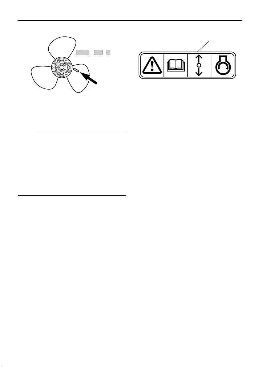
x
-
123
General information
1
ZMU04604
1. Propeller diameter in inches
2. Propeller pitch in inches
3. Type of propeller (propeller mark)
NOTE:
Select a propeller which will allow the engine
to reach the middle or upper half of the operating range at full throttle with the maximum
boat load. If operating conditions such as light
boat loads then allow the engine r/min to rise
above the maximum recommended range, reduce the throttle setting to maintain the engine in the proper operating range.
For instructions on propeller removal and installation, see page 34.
EMU25760
Start-in-gear protection
Yamaha outboard motors affixed with the pictured label or Yamaha-approved remote control units are equipped with start-in-gear
protection device(s). This feature permits the
engine to be started only when it is in neutral.
Always select neutral before starting the engine.
ZMU01713
1. Start-in-gear protection label
4

Basic components
EMU25795
Main components
NOTE:
* May not be exactly as shown; also may not be included as standard equipment on all models.
1. Manual starter handle
2. Tiller handle
3. Choke knob
4. Engine stop button/Engine stop lanyard
switch
5. Tilt lock lever
6. Clamp screw
7. Trim rod
8. Propeller
9. Cooling water inlet
10.Anti-cavitation plate
11.Clamp bracket
12.Rope attachment
13.Gear shift lever
14.Top cowling
15.Fuel tank
5
EMU25802
Fuel tank
If your model was equipped with a portable
fuel tank, its function is as follows.
EWM00020
WARNING
The fuel tank supplied with this engine is
its dedicated fuel reservoir and must not
be used as a fuel storage container. Commercial users should conform to relevant
licensing or approval authority regulations.
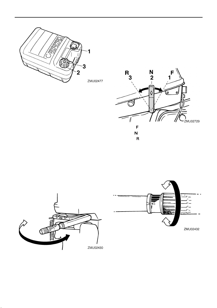
1. Fuel joint
2. Fuel tank cap
3. Air vent screw
EMU25830
Fuel joint
This joint is used to connect the fuel line.
EMU25850
Fuel tank cap
This cap seals the fuel tank. When removed,
the tank can be filled with fuel. To remove the
cap, turn it counterclockwise.
EMU25860
Air vent screw
This screw is on the fuel tank cap. To loosen
the screw, turn it counterclockwise.
EMU25911
Tiller handle
To change direction, move the tiller handle to
the left or right as necessary.
Basic components
EMU25922
Gear shift lever
Pulling the gear shift lever towards you puts
the engine in forward gear so that the boat
moves ahead. Pushing the lever away from
you puts the engine in reverse gear so that the
boat moves astern.
1. Forward “”
2. Neutral “”
3. Reverse “”
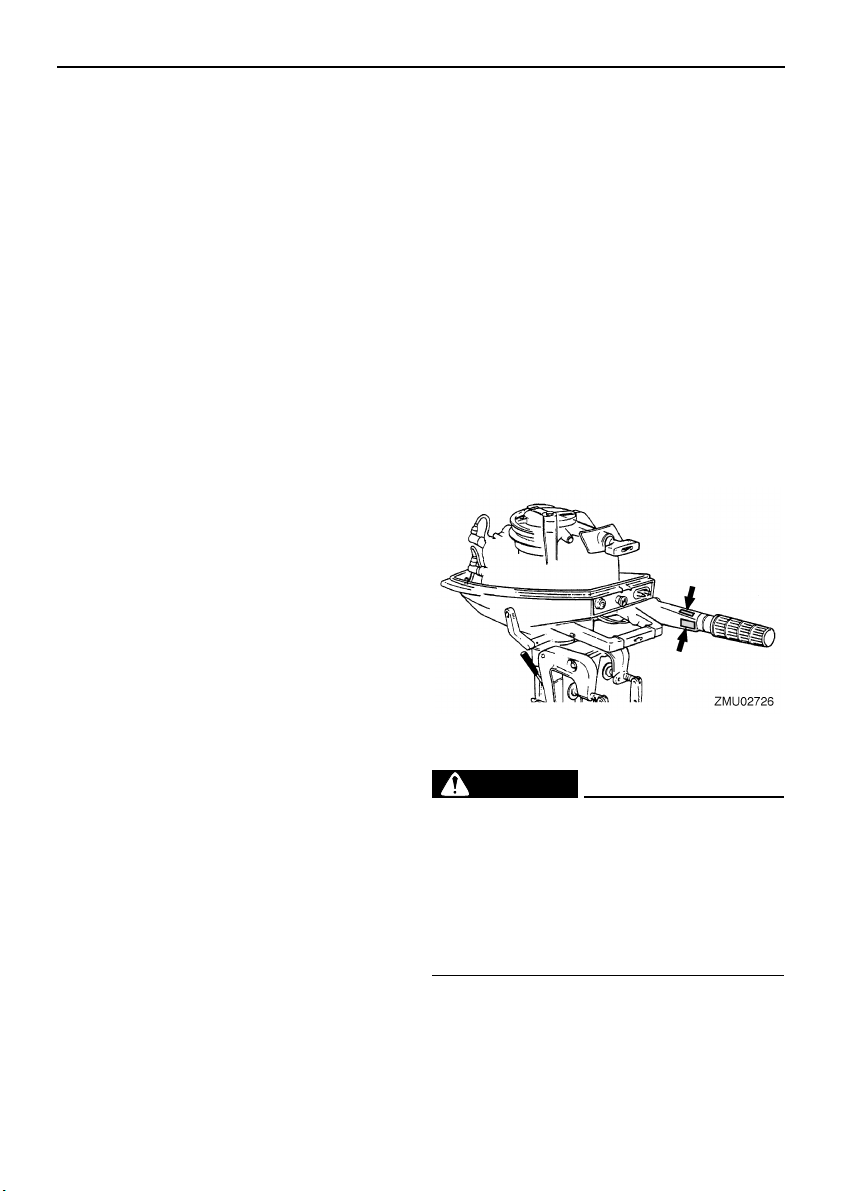
EMU25941
Throttle grip
The throttle grip is on the tiller handle. Turn
the grip counterclockwise to increase speed
and clockwise to decrease speed.
EMU25961
Throttle indicator
The fuel consumption curve on the throttle indicator shows the relative amount of fuel consumed for each throttle position. Choose the
setting that offers the best performance and
fuel economy for the desired operation.
6
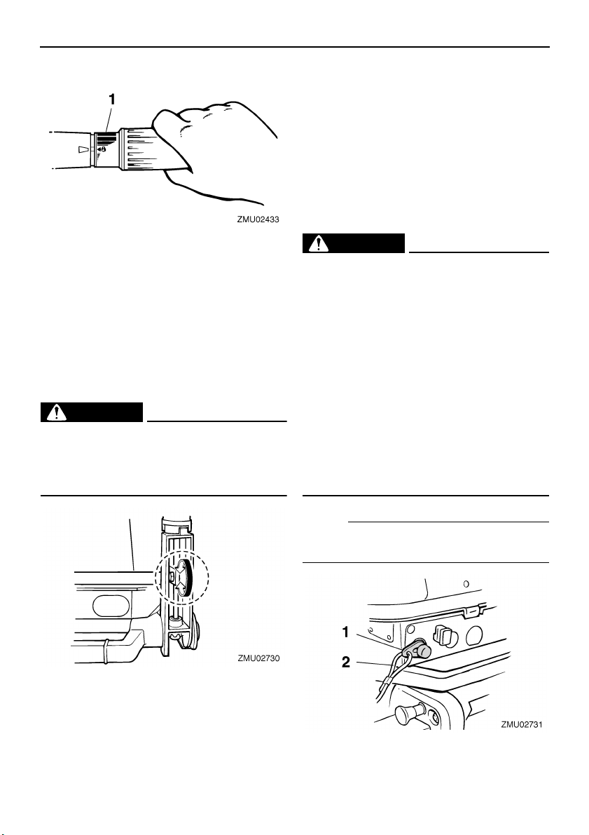
Basic components
1. Throttle indicator
EMU25970
Throttle friction adjuster
A friction device provides adjustable resistance to movement of the throttle grip or the
remote control lever, and can be set according to operator preference.
To increase resistance, turn the adjuster
clockwise. To decrease resistance, turn the
adjuster counterclockwise.
EWM00030
WARNING
Do not overtighten the friction adjuster. If
there is too much resistance, it could be
difficult to move throttle lever or grip,
which could result in an accident.
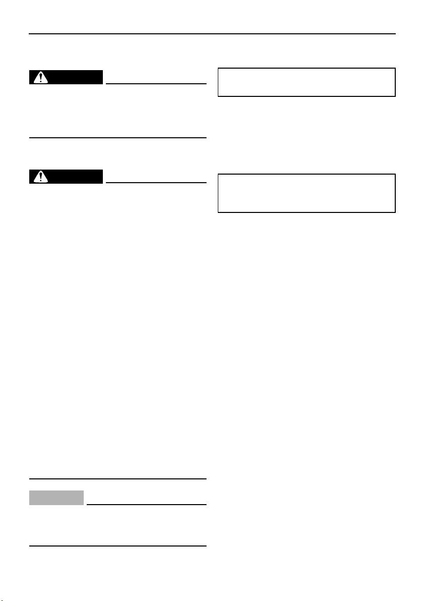
EMU25990
Engine stop lanyard switch
The lock plate must be attached to the engine
stop switch for the engine to run. The lanyard
should be attached to a secure place on the
operator’s clothing, or arm or leg. Should the
operator fall overboard or leave the helm, the
lanyard will pull out the lock plate, stopping ignition to the engine. This will prevent the boat
from running away under power.
EWM00120
WARNING
● Attach the engine stop switch lanyard to
a secure place on your clothing, or your
arm or leg while operating.
● Do not attach the lanyard to clothing
that could tear loose. Do not route the
lanyard where it could become entangled, preventing it from functioning.
● Avoid accidentally pulling the lanyard
during normal operation. Loss of engine
power means the loss of most steering
control. Also, without engine power, the
boat could slow rapidly. This could
cause people and objects in the boat to
be thrown forward.
When constant speed is desired, tighten the
adjuster to maintain the desired throttle setting.
7
NOTE:
The engine cannot be started with the lock
plate removed.
1. Lock plate
2. Lanyard
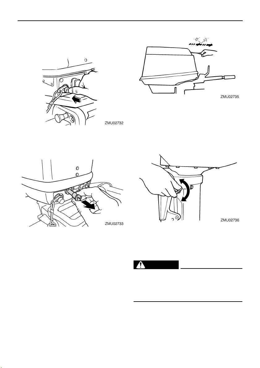
EMU26001
Engine stop button
To open the ignition circuit and stop the engine, push this button.
EMU26011
Choke knob for pull type
To supply the engine with the rich fuel mixture
required to start, pull out this knob.
Basic components
EMU26122
Steering friction adjuster
A friction device provides adjustable resistance to the steering mechanism, and can be
set according to operator preference. An adjusting screw or bolt is located on the swivel
bracket.
EMU26070
Manual starter handle
To start the engine, first gently pull the handle
out until resistance is felt. From that position,
then pull the handle straight out quickly to
crank the engine.
To increase resistance, turn the adjuster
clockwise.
To decrease resistance, turn the adjuster
counterclockwise.
EWM00040
WARNING
Do not overtighten the friction adjuster. If
there is too much resistance, it could be
difficult to steer, which could result in an
accident.
EMU26261
Trim rod (tilt pin)
The position of the trim rod determines the
minimum trim angle of the outboard motor in
relation to the transom.
8
Basic components
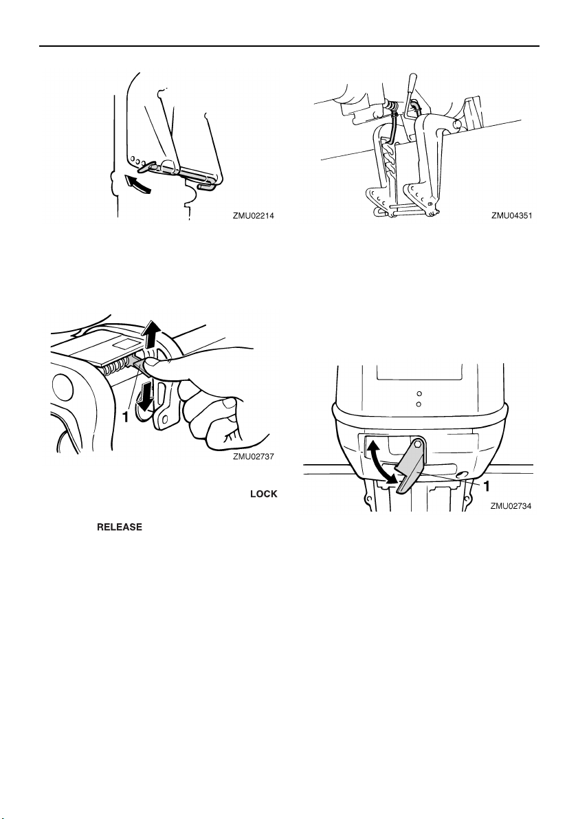
EMU30460
Tilt lock mechanism
The tilt lock mechanism is used to prevent the
outboard motor from lifting out of the water
when in reverse gear.
EMU26372
Top cowling lock lever(s) (turn type)
To remove the engine top cowling, turn the
lock lever(s) and lift off the cowling. When installing the cowling, check to be sure it fits
properly in the rubber seal. Then lock the
cowling again by returning the lever(s) to the
lock position.
1. Tilt lock lever
To lock it, set the tilt lock lever in the “”
(lock) position. To release, push the tilt lock lever in the “” (release) position.
EMU26330
Tilt support bar
The tilt support bar keeps the outboard motor
in the tilted up position.
1. Top cowling lock lever(s)
9
Operation
EMU26901
Installation
ECM00110
CAUTION:
Incorrect engine height or obstructions to
smooth water flow (such as the design or
condition of the boat, or accessories such
as transom ladders or depth finder transducers) can create airborne water spray
while the boat is cruising. Severe engine
damage may result if the motor is operated continuously in the presence of airborne water spray.
NOTE:
During water testing check the buoyancy of
the boat, at rest, with its maximum load.
Check that the static water level on the exhaust housing is low enough to prevent water
entry into the powerhead, when water rises
due to waves when the outboard is not running.
EMU26910
Mounting the outboard motor
EWM00820
WARNING
● Overpowering a boat could cause se-
vere instability. Do not install an outboard motor with more horsepower than
the maximum rating on the capacity
plate of the boat. If the boat does not
have a capacity plate, consult the boat
manufacturer.
● The information presented in this sec-
tion is intended as reference only. It is
not possible to provide complete instructions for every possible boat and
motor combination. Proper mounting
depends in part on experience and the
specific boat and motor combination.
EWM00830
WARNING
Improper mounting of the outboard motor
could result in hazardous conditions such
as poor handling, loss of control, or fire
hazards. Observe the following:
● For permanently mounted models, your
dealer or other person experienced in
proper rigging should mount the motor.
If you are mounting the motor yourself,
you should be trained by an experienced
person.
● For portable models, your dealer or oth-
er person experienced in proper outboard motor mounting should show you
how to mount your motor.
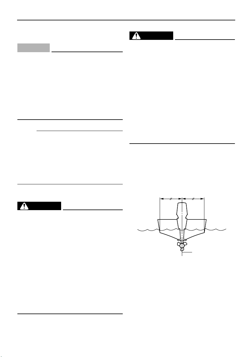
Mount the outboard motor on the center line
(keel line) of the boat, and ensure that the
boat itself is well balanced. Otherwise the
boat will be hard to steer. For boats without a
keel or which are asymmetrical, consult your
dealer.
1
1. Center line (keel line)
EMU26920
Mounting height
To run your boat at optimum efficiency, the
water resistance (drag) of the boat and outboard motor must be made as little as possible. The mounting height of the outboard
motor greatly affects the water resistance. If
the mounting height is too high, cavitation
ZMU01760
10
 Loading...