


Yamaha DX7 MiniMAX Expansion Install
1: Introduction
The DX7 MiniMAX a simple option board that provides increased memory and control of the DX7.
While the installation is fairly simple, it still requires patience and general electronics
knowledge. We accept no responsibility for the work you perform on your DX7. Read over
the following installation description and if you feel you are not capable of the work
required, turn the project over to a qualified technician
Precautions!
High Voltage Safety Warning
Unplug the audio cable. Turn the DX7 power switch OFF and unplug it from the wall.
Disconnect any other connected cables before opening the DX7.
ESD Precautions and Proper Handling Procedures
You should observe standard static-safe handling behavior when working with sensitive electronic
equipment such as synthesizers:
o Avoid carpets in cool, dry areas.
o Dissipate static electricity before handling any system components by touching a
grounded metal object.
o If possible, use anti-static devices, such as wrist straps and floor mats.
o Take care when installing the board. Prevent damage to the connectors by aligning
connector pins before you apply pressure. A damaged pin can render the board unusable
and can cause damage to system components at power-on.
o If disconnecting a cable, always pull on the cable connector, not on the cable itself.
Tools Required
o Standard Philips screwdriver.
o Standard flat-head screwdriver (small).
Condition of DX7
While the DX7 MiniMAX will replace the functionality of damaged or missing EPROM and/or
SRAM chips, it will not correct other problems your vintage synthesizer may have. It is
recommended that the synth be in otherwise good condition before beginning the installation. For
instance, the battery voltage should be checked and the battery replaced/repaired by a tech if
necessary. Sockets for the EPROM and SRAM chips should be in good working order and not be
DX7 MiniMAX Page 1 of 6 Install v2.10
www.musictechnologiesgroup.com Preliminary
dirty, oxidized, rusted or otherwise compromised. If repair is required, do it before installing the
DX7 MiniMAX.
2: Installation
Back up your patches if they are important to you!
Open the DX7
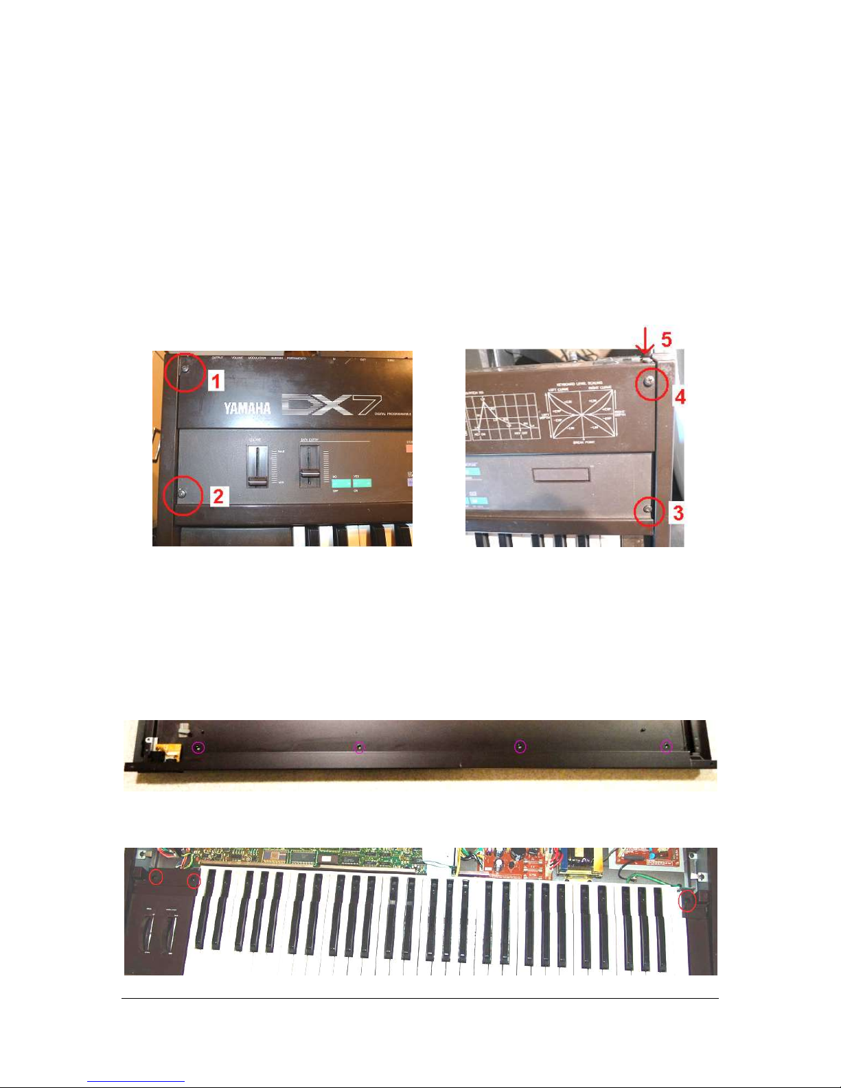
Using a Philips head screwdriver, remove the 5 screws from the front panel. Two are located
on the left front. Two are located on the right front. A final one is located on the right rear. Set the
screws aside, noting that the rear panel one is the shortest.
(Re)Move the Keybed & Remove the Keyboard Rail
It can be difficult to see the delicate pins when installing the DX7 MiniMAX board. By moving the
keybed (the chassis with the keys) and removing the silver keyboard rail, you will have better
sight lines and freedom of movement when installing the DX7 MiniMAX board.
.
Remove the 4 large external screws from the underside of the keyboard along the front
edge. The photo below shows the inside front edge of the empty case bottom and illustrates the
location of the 4 screws. You will, of course, be unscrewing from the DX7 underside.
Loosen the 3 internal screws at the extreme right and left ends that hold the keybed in
place. It is not necessary to extract them from the holes they reside in.
DX7 MiniMAX Page 2 of 6 Install v2.10
www.musictechnologiesgroup.com Preliminary
 Loading...