


®
YAMAHA
AUTHORIZED
PRODUCT MANUAL
DIGITAL PROGRAMMABLE ALGORITHM SYNTHESIZER

®
YAMAHA
DIGITAL PROGRAMMABLE ALGORITHM SYNTHESIZER
OWNER’S
MANUAL

CONGRATULATIONS!
Your Yamaha DX100 Digital Programmable Algorithm Synthesizer incorporates stateof-the-art digital FM tone generation technology, providing extraordinarily vibrant, rich
voices and outstanding playability. The DX100 has a programmable 24-voice INTERNAL
memory (RAM) from which any voice can be selected at the touch of a button, two
96-voice PRESET (ROM) memories (a total of 192 fine preset voices!), a 96-voice BANK
memory that permits storage of PRESET voices in any configuration for one-touch selection, and a cassette interface that permits unlimited storage of FM voices. Of course,
the DX100 is fully programmable, allowing you to create your own FM voices or sound
effects. Broad MIDI compatibility is also provided so the DX100 can control or be
controlled via other MIDI-compatible music equipment.
To ensure that you gain maximum benefit from all the performance and flexibility provided
by the DX100, we urge you to read this owner’s manual thoroughly while actually trying
out all of the available functions.
CONTENTS
UP..
CHAPTERI:SETTING
1.
Audio
Outputs
OptionalFoot
2.
Optional
3.
4. Headphones..............................................................
MIDI
5.
6.
Cassette
7.
Battery,ACPower Adaptor..
8. Power-ON, Low Battery LED Indicator
9.LCD
10.ID
11.
When
CHAPTER
1.
DX100 Voice Memory Configuration..
2. The
3.
TheBANK
4. The192-Voice
CHAPTER
1.
Accessing
2.
EnteringFunction
3. The
4.
TuningFunctions..
5. Memory Management Function..
6.MIDI
BC-1
Terminals..
...................................................................
Contrast
Function..
II:
INTERNAL
The
PRESET SEARCH..
III: THE
Performance
.............................................................
using
dry
PLAYING THE DXl00
PLAY
SHIFT
Mode..
FUNCTIONMODE..
the
Functions
................................................
..........................................................
Switch..
Breath
Control...............................................
PLAY
PRESET
FUNCTION
.........................................................
............................................
Controller..............................
.......................................................
....................................
....................
batteries.........................................
...................................
......................
Mode
.....................................
Mode..
...........................................
..................................................
Memory..............................
.................................................
..............................
Mode..
............................
Data
............................................
Parameters.................................
....................................................
.............................
3
3
3
3
3
3
3
3
4
4
4
5
6
6
7
8
8
9
10
11
11
11
11
17
17
22
CHAPTERIV: VOICE PROGRAMMING
Synthesis..
1.
TheBasics
2. TheEDIT and
TheVoice
3.
4.STORING
5. Two Approaches to Creating Your Own Voices
CHAPTER V: VOICE PROGRAMMING EXAMPLE..
GENERALSPECIFICATIONS..
MIDI
DATA
1.
Transmission
2.
Transmission
Reception
3.
4.
Reception
5.
System
VOICE/FUNCTION
DATANAME..
of FM
COMPAREmodes.............................
Parameters
Voice
FORMAT..
Conditions
Data..
Conditions..
Data.........................................................
Exclusive
DATA..
....................................................................
.............................................
Data................................................
...........................................
.......................................................
.................................................
.............................................
Data............................................
.................................................
.............................
...................................
.........................................
......
...........
24
24
29
30
38
38
40
44
45
45
46
49
50
53
57
58
1

1. Location
2. Cleaning
3. Service and
Modifications
4. Relocation
5. HandIing
PRECAUTIONS
Avoid locations exposed to direct sunlight or other sources of heat. Also avoid
locations subject to vibration, excessive dust, cold or moisture.
Do not attempt to clean the exterior with chemical solvents, as this may damage
the finish. Clean with a soft, dry cloth.
Do not open the cabinet or attempt to make your own repairs or modifications to
any part of the instrument. Such actions may not only result in electrical shock or
damage, but will also void the product warranty. Refer all servicing to a qualified
Yamaha service center.
When moving the instrument be sure to unplug the AC adaptor (PA-1210, optional)
as well as all other connecting cables.
Avoid applying excessive force to switches and slide controls, dropping or rough
handling. The DX100 is ruggedly constructed using reliable solid-state circuitry,
nonetheless it is a fine instrument that should be treated with care.
6. Electrical Storms
(Lightning)
7. EIectromagnetic
Fields
Digital circuitry such as that used in the DX100 is sensitive to voltage spikes and
surges. Be sure to remove all connecting cables in the event of an electrical storm.
Digital circuitry is also sensitive to electromagnetic fields such as those produced
by television sets, radio receivers, transmitters, transceivers, etc. The DX100 should
be kept at least several feet from such sources in order to prevent possible random
malfunctions.
2

1. Audio Outputs
2. Optional Foot
Switch
3. Optional BC-1
Breath Con troller
4. Headphones
5. MIDI Terminals
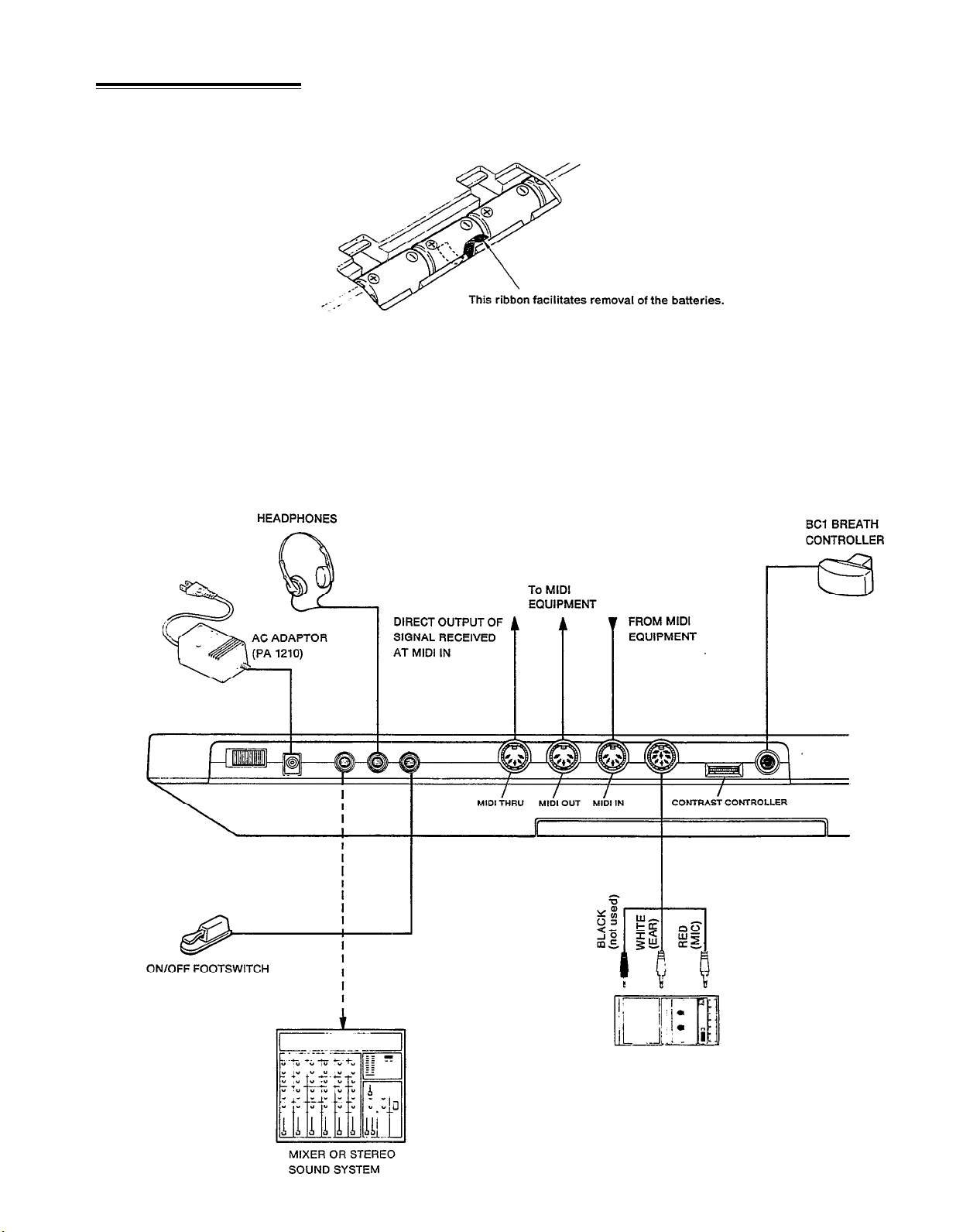
CHAPTER I: SETTING UP
The DX100 has a single mono audio output for its tone generator channel. This
is labelled OUTPUT. It permits sending a mono signal to either a mono or stereo
sound system, or a mixing console for recording or PA applications.
The FOOT SW phone jack is for an optional footswitch. It accepts a Yamaha FC-4
or FC-5 footswitch or equivalent for portamento/sustain control: press for por-
tamento or sustain; release to damp or turn portamento off.
Yamaha’s unique BC-1 breath controller is plugged into the mini-jack on the rear
panel.
The PHONES jack accepts any standard pair of stereo headphones. The audio signal
is delivered to the headphones in mono. Headphone volume is controlled via the
VOLUME control on the top panel.
These terminals are used when connecting the DX100 to other MIDI (Musical
Instrument Digital Interface) compatible equipment such as digital sequence re-
corders, modular FM voice generators, drum machines, etc. The MIDI OUT terminal
transmits MIDI data from the DX100 to other MIDI equipment. The MIDI OUT
terminal will normally be connected to the MIDI IN terminal of the receiving
equipment. The MIDI IN terminal receives MIDI data from external MIDI equipment
such as a digital sequence recorder, music computer or modular FM voice generator.
The DX100’s MIDI IN terminal will normally be connected to the MIDI OUT terminal
of the transmitting equipment. The MIDI THRU terminal re-transmits the data re-
ceived at the MIDI IN terminal. Thus, data received via the DX100 MIDI IN terminal
can be simultaneously sent to other MIDI equipment.
6. Cassette
7. Battery, AC Power
Adaptor
The DIN connector end of the supplied cassette cable is plugged into the DX100
CASSETTE connector. The three plugs on the other end of the cable should be
connected to a cassette data recorder (the kind normally used with personal
computers, etc.) as follows:
RED
WHITE
BLACK
cassette deck microphone input.
cassette deck earphone output.
cassette deck remote input (where applicable)
The DX100 operates off 6 “C” size batteries which are inserted in the battery
compartment in the bottom of the synthesizer. Or, insert the optional PA-1210
AC power adaptor cord into the DC IN jack located on the rear panel of the DX100,
and then plug the standard 2-prong plug into an AC wall socket. Be sure that your
local line voltage matches that specified on the PA-l210. You will find the POWER
switch next to the DC IN jack on the rear panel of the DX100.
3
8. Power-ON, Low
Battery LED Indicator
9. LCD Contrast
Control
10. ID Function
NOTE:
When setting up your system, be sure to turn the DX100 and any effects units
used on BEFORE turning the main amplifier system on. This will prevent the
initial power-on shock surge from possibly damaging your amplifier and
speaker system.
The DX100 features a Power-ON LED indicator, located immediately to the right
of the LCD indicator on the top panel. It glows when the Power switch on the rear
panel is turned ON. Additionally, it flashes to warn of low battery power should
such an occasion arise (batteries provide approximately 10 hours of continual use.)
An LCD Contrast Control, located on the back panel immediately behind the LCD
indicator, is provided in the DX100 to provide a clearly visible readout under most
lighting circumstances.
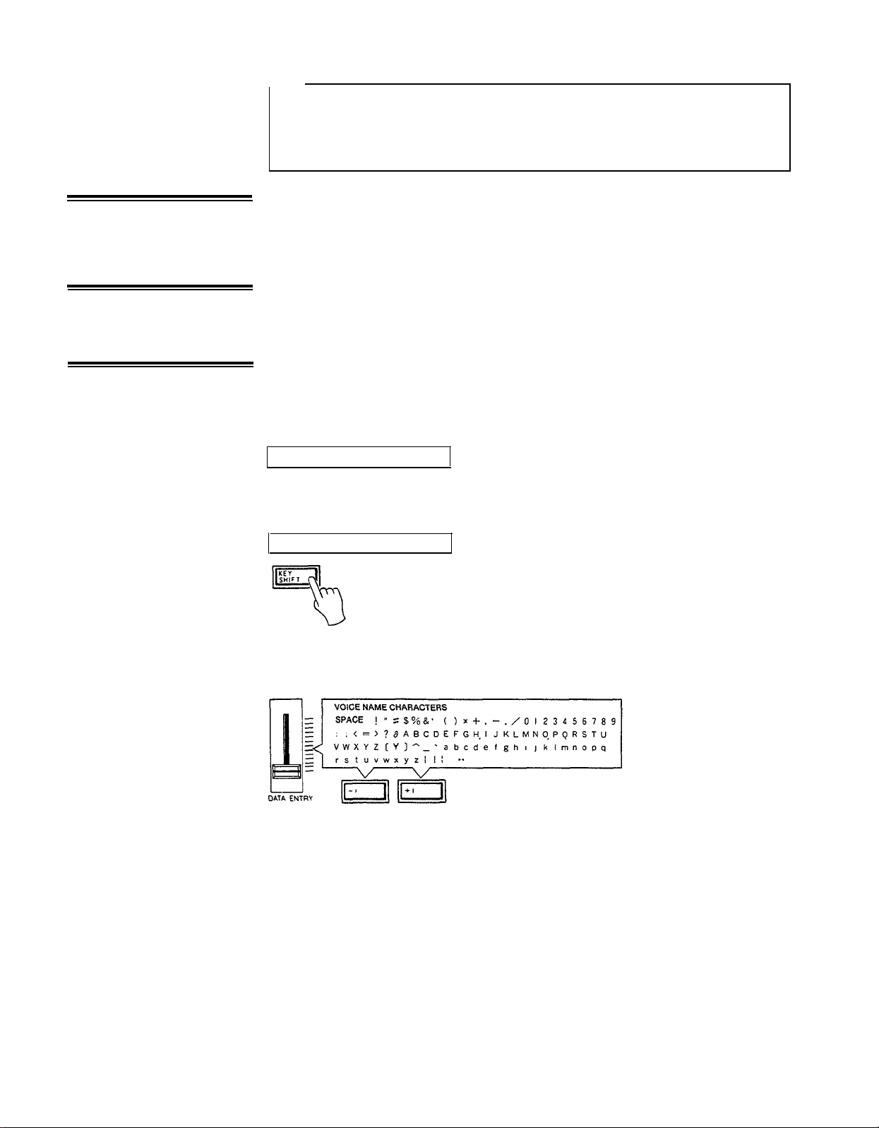
It is possible to change the “Welcome to DX!” message which appears when the
power is first switched ON to anything you like-your name, for example. To change
the ID, hold the KEY SHIFT button while turning the power ON. The current ID
message will be displayed with a cursor over the first character.
<Welcome to DX!>
The cursor can then be moved to any character position on the display by successively pressing the KEY SHIFT button.
<Welcome to DX!>
Choose the position to enter a new character, then using the DATA ENTRY slider
or buttons, select the new character from the available character set.
Move the cursor to the next character position and enter the next character as
described above. When your new ID message is complete, simply press any button
other than the KEY SHIFT, DATA ENTRY, STORE or FUNCTION buttons to enter
the normal operation mode. The new ID message you have entered will now be
displayed every time you turn the instrument ON.
4
11. W
hen using dry
batteries
DX100 CONNECTIONS
Insert 6 AA size dry batteries (optional). Remove the cover at the rear of the main
unit and set the batteries while checking the polarity. When doing so, be sure to
set
the ribbon for removing batteries under the second one from the left.
After inserting the dry batteries, replace the cover of the battery case.
*AC power operation
When operating this unit on AC power, it is recommended to use an economical
AC adapter (optional).
5
CHAPTER II: PLAYING THE DX100
1. DX100 Voice
Memory
Configuration
The DX100 has three different voice memories which serve different purposes. They
are:
The 24-voice INTERNAL memory.
This voice memory is used for quick selection of voices for performance, and it is
to this memory that original voices you have edited or programmed are initially
stored. Cassette LOAD and STORE operations are also carried out to and from the
24-voice INTERNAL memory. Voices from the 192-voice PRESET memory may
also be stored in the INTERNAL memory.
The 96-voice BANK memory (4 BANKS x 24 voices each).
The BANK memory incorporates four 24-voice BANKS-A, B, C and D. The BANK
is most useful for storing groups of voices you have arranged for specific purposes.
The different banks may be programmed with different voice groups you need for
different “sets” in a performance, you can categorize your voices into BANK
S
(i.e.
piano-type voices in one bank, brass in another, etc.), any combination you like.
The BANK can be loaded with voices from the PRESET memory (described below)
or from the INTERNAL memory using the EDIT BANK function.
The 192-voice PRESET memory.
This is a read-only memory which contains 192 FM voices. These are organized
into two groups of 96 voices each. The first group is accessible in the NORMAL
6
mode, while the second group is accessed in the SHIFT mode (these modes will
be described below. These voices may be selected and stored in the BANK or
INTERNAL memories as desired. They can also be directly accessed and played
using the PRESET SEARCH function.
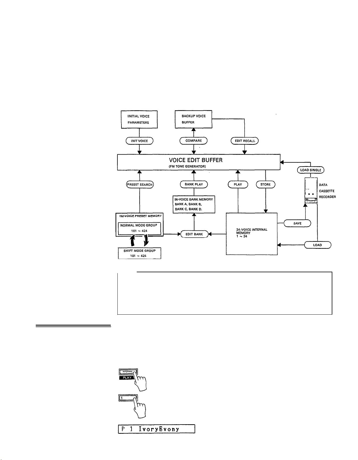
The chart below shows the overall DX100 voice memory configuration. The VOICE
EDIT BUFFER is a special memory into which a voice is called when selected.
Whether you select a voice from the INTERNAL memory, the BANK memory, or
the PRESET memory, it is placed in the VOICE EDIT BUFFER from which it can
be played, edited, stored in another memory location or saved onto cassette.
2. The INTERNAL
PLAY Mode
NOTE:
The voices in the PRESET memory are numbered as follows: each group of
96 voices–the NORMAL group and the SHIFT group–is further subdivided
into four groups of 24 voices each (101–124, 201–224, 301–324, and
401–424). Thus you have NORMAL group voices 101–424, and SHIFT group
voices 101–424.
To access the 24–voice INTERNAL memory, enter the INTERNAL PLAY mode by
pressing the INTERNAL PLAY button.
Next, select a voice from the INTERNAL
memory by pressing the corresponding voice selector button (1–24). At this point,
the LCD display will indicate the voice number, and voice name. These are preceded
by a "P", indicating that the INTERNAL PLAY mode has been selected.
7
3. The BANK PLAY
Mode
In this mode, you can play any of the voices currently in the DX100’s 24-voice
INTERNAL memory individually.
The BANK PLAY mode enables you to access the 96 BANK memory locations.
These initially contain the first group of 96 voices from the 192-voice PRESET
ROM. Using the SHIFT mode, however, you can also access the second group
of presets while in the BANK PLAY mode. Later, you can store any voices you like
in any order in the these BANKS.
While in the INTERNAL PLAY mode, press any of the BANK buttons;BANK
A–BANK D. This will select the appropriate BANK, and the 24 voices in that bank
can be selected by pressing any of the DX100’s 24 voice buttons.
PA 2 NewElectro
The SHlFT Mode
By entering the DX100 SHIFT mode while in BANK PLAY, the correspondingly
numbered voice from the second group (SHIFT group) of preset voices will be
selected. Note that in the BANK PLAY mode this only applies to voices which have
been stored in the BANK memory from the 192-voice PRESET memory. Voices
stored in the BANK from the 24-voice INTERNAL memory will not change when
the SHIFT mode is selected.
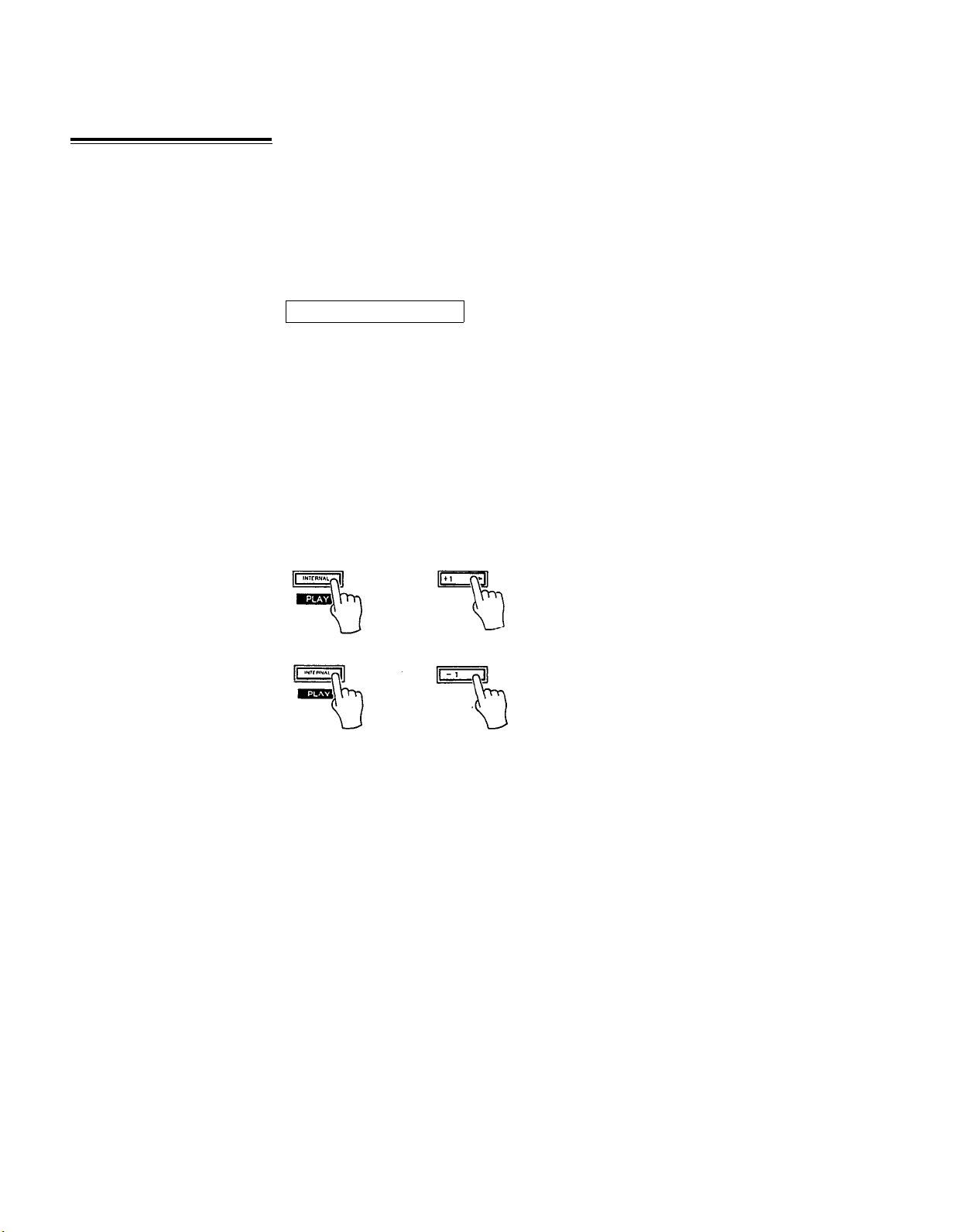
To enter the SHIFT mode, hold down the INTERNAL PLAY button and press the
+1 button. To return to the NORMAL mode hold down the INTERNAL PLAY button
and press the -1 button.
8
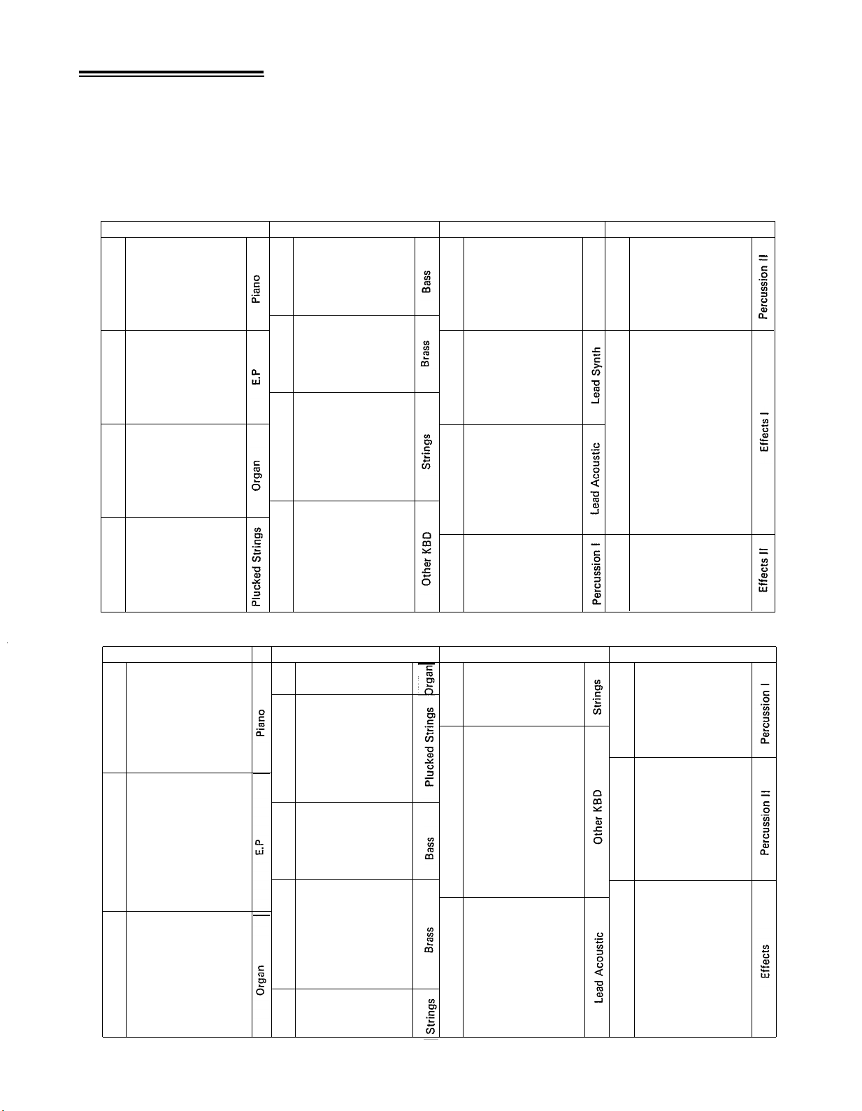
The DX100 comes with 192 different pre-programmed voices in an internal ROM
4. The 192-Voice
PRESET Memory
(Read Only Memory).These voiced
24-voice INTERNAL memory, or into any location in the DX100 bank memory.
THE 192 PRESET ROM VOICES
NORMAL MODE VOICES
can
be loaded singly into the DX100's selectable
Group 1
01
IvoryEbony
02
Oprt piano
03 Honkey Tonk
Elec Grand
04
05
Pianobells
Acous Elec
06
Old Electro
07
NewElectro
08
HighTimes09
Wood Piano
10
Vibrabelle
11
Pianobrass
12
JazzORGAN
13
Ham<n>Eggs14
15
ClubOrgan
<6 Tease>
16
17GentlePipe
18FullRanks
19
Plukguitar
SoftHarp
20
21
JazzGuit
22OldBanjo
23
Kotokoto
FolkGuit
24
Group 2
Solid Brass
01
Synthe Bass
02
03
Mono Bass
04
Elec Bass
05 Fretless
06 Horns
07
Flugelhorn
Hard Brass
08
09
Power Brass
10 BC1Trumpet
11 Strings
12
Silk Cello
13 Orchestra
14
Solo Violin
15 Box Cello
16 Richstring
5th String
17
18
Harpsi low
19
Harpsi Hi
Fuzz Clav
20
21 Clear Clav
22
Squeezebox
23
Celeste
Circustime
24
Group 3
01Easy Synth
Easy Clav
02
>>WOW<<
03
Metal Keys04
PickPluck05
S/H Synth
06
07Heavysynth
Harmosolo
08
09Feed Lead
Mono Lead
10
Lyrisyn
11
12
Schmooch
Claranette
13
14Pan Floot
15Lead Reed
Mono Sax
16
Flutewood
17
<BC1> Sax
18
BC1 Hrmnca
19
Timpani
20
Xylosnare
21
22Synballs
23
Clockworks
24HeiferBell
Group 4
Glocken
01
02Hamarimba
Steel Drums
03
04
Tube Bells
Templegong
05
06
Good Vibes
Racing Car
07
08Helicopter
Alarm Call
09
10
Dopplar FX
11Storm Wind
Birds
12
Hole in 1
13
<<Smash>>
14
15
FM SQUARE
16
FM PULSE
17FMSAWTOOTH
LFO NOISE
18
19
PINK NOISE
20
Windbells
21
Synvox
22Whistling
23
Voices
24
Mars to ??
Shift Mode Voices
Group 1
01 Piano 1
02
Piano 2
Piano 3
03
04
Piano Vel
Honkeyton 2
05
06
Deep Grand
PhaseGrand
07
08Left Hand
09Elec Grnd
10E Grnd Vel
11
E Piano 1
E Piano 2
12
1314E Piano 3
E P String
15
Hard Times
PercoPiano
16
17
Organ 1
18
Organ 2
ElecOrgan
19
20
16842F
21
Theater
SmallPipe
22
23MidPipe
BigPipe
24
01
02
03
04 Fuzz Guit
05
06
07 Harp 1
08
09
10
11
12
13
14
15 Bass 1
16
17 Brass 3
18
19
20 Brass 6
21 Brass 7
22
23
24
Group 2
Clickorgan
Drawbars
Guitar 2
Brt Guitar
Zither
Lute
Sitar
SynthBass1
SynthBass2
Pluck Bass
Flap Bass
Uprt Bass
Bass 2
Brass 4
Brass 5
Strings1
Strings 2
Strings 3
Group 3
01
Rich Strg 1
02
Rich Strg 2
Rich Strg 3
03
Pizzicato
04
05Harpsicrd 1
Harpsicrd 2
06
Clav 1
07
08
Clav 2
09
Mute Clav 1
10Mute Clav 2
LeadSynth 1
11
12
Cheeky
RubberBand
13
Hollowlead
14
Huff Talk
15
Harmonica 1
16
Harmonica 2
17
18 Horn
Flute 1
19
20
Flute 2
21 Oboe
Trombone
22
23
BC1 Horns
24
Bassoon
Group4
Snare Bass
01
Snare Drum 1
02
03
Snare Drum 2
0
4Tom Toms
Steel Drum 2
05
Synth Perc
06
07
Xylophone 1
Xylophone 2
08
09Marimba
10Mamarimba
Glocken 2
11
Vibe
12
Tublar Bells
13
14Bells
Wild War!!
15
YS11
16
17
Wave
Winds18
Shogakko
19
Fantasy
20
Sp
ace chime
21
22
Ghosties
2
3Space Talk
24
Zing Plop
The PRESET voice can also be accessed directly and played using the PRESET
SEARCH function.
9

PRESET SEARCH
This function allows you to directly access the voices in the PRESET memory, in
the order they appear in the PRESET memory.
PRESET SEARCH is accessed in the FUNCTION mode. To enter the FUNCTION
mode press the FUNCTION button. Then press any of the PRESET SEARCH selectors to access the corresponding voices (these are the same as the BANK A–D
selectors used in the BANK PLAY mode). In the NORMAL (NON-SHIFT) mode,
the PRESET SEARCH selectors call PRESET voice groups 101–124, 201–224,
301–324, and 401–424 from the NORMAL preset voice group. In the SHIFT mode
(described in “The BANK PLAY Mode”, above), the correspondingly numbered
voices from the SHIFT preset voice group are selected. The 24 voices in each group
are selected by pressing the corresponding voice selector. After selecting PRESET
SEARCH 101–124, for example, the LCD will appear as follows:
“F” indicates that you are in the FUNCTION mode PRESET SEARCH function.
This function lets you review the voices in the PRESET memory. It is also possible
to store a voice selected in this mode into any of the 24–voice INTERNAL memory
locations using the STORE function described later in this manual.
10
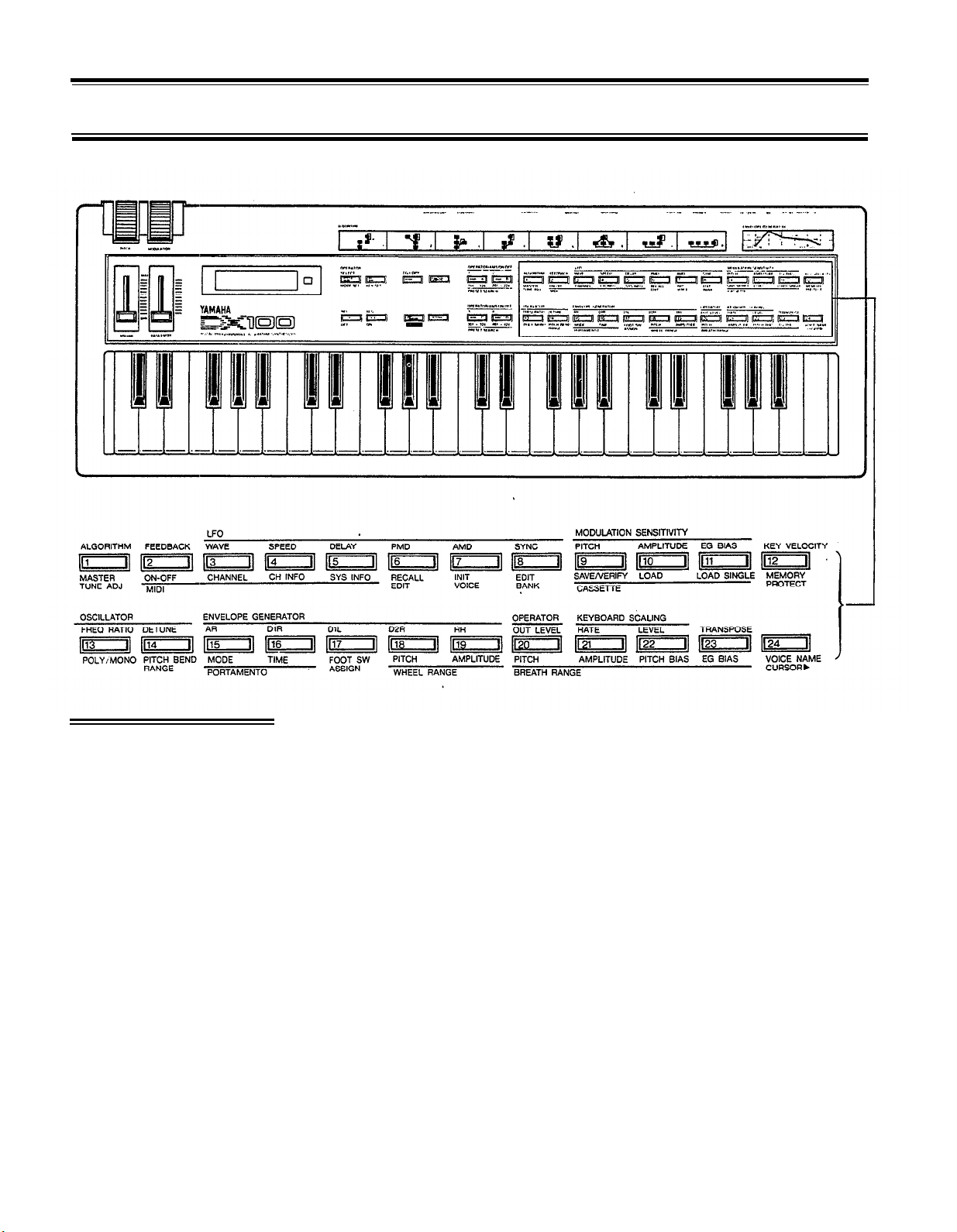
CHAPTER III: THE FUNCTION MODE
The FUNCTION mode permits access to four groups of functions:
management functions, and performance functions. In this chapter we’ll describe each of these functions; what
they do and how they are programmed.
The FUNCTION mode is called by pressing the FUNCTION button. Individual
1. Accessing the
FUNCTION Mode
2. Entering Function
Data
parameters to be programmed are then called by pressing the appropriate voice
button. Note that when the FUNCTION mode is active, pressing a voice button
calls the corresponding FUNCTION parameter. These functions are printed in brown
below each voice button. Note also that there are two exceptions: the PITCH B
(Pitch Bend) MODE SET and KEY SHIFT KEY SET buttons are NOT included among
the voice buttons. These function buttons are located immediately above the DATA
ENTRY -1 and +1 buttons. When the FUNCTION mode is called, the LCD should
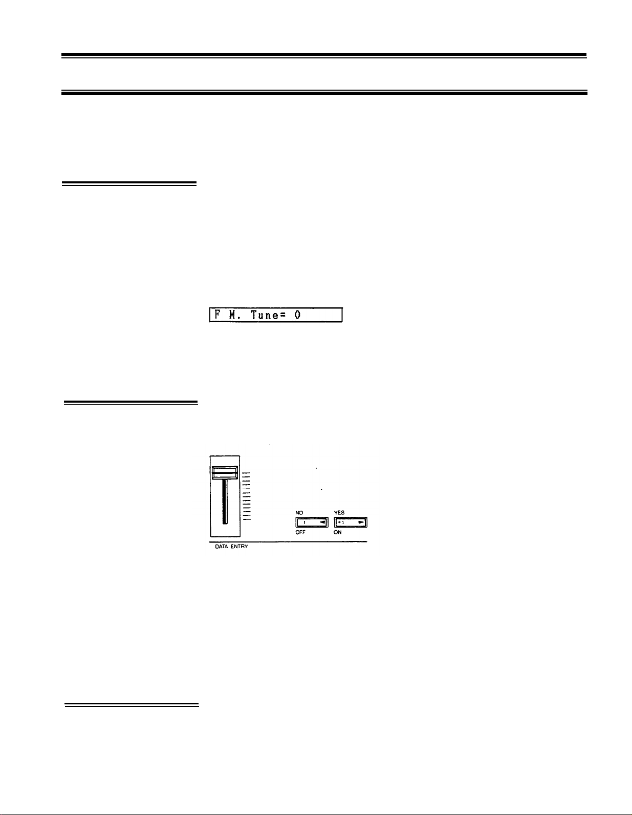
look something like this.
The display will read “F M.Tune= 0”, indicating that the FUNCTION mode is active,
plus the name of the selected function and its current data. In the example above,
the MASTER TUNE function is called (press the 1 button), and the data is currently
set at 0.
Once the desired function has been selected, its value can be altered using either
the linear DATA ENTRY slider located to the left of the panel, or the adjacent -1 /+1
buttons.
tuning functions, MIDI functions, memory
3. The Performance
Parameters
Moving the DATA ENTRY slider away from you increases the value of the selected
parameter, and moving the control towards you decreases the data value. Pressing
the -1 button decreases the value of the selected parameter by one (decrements),
and pressing the +1 button increases the value by one (increments). While the
DATA entry slider is valuable for quickly approaching the desired value with parameters that have a large data range, the +1 and -1 buttons permit precise
step-wise location of a specific value. The switches are also easier to use with
parameters that only have two values, i.e. ON (1) or OFF (0). In some cases you
will be required to answer YES or NO to prompts which will appear on the LCD
display. The -1 /+1 buttons are also used for this purpose.
“Performance parameters” are programmable parameters which pertain mainly to
real-time performance effects, such as how the pitch bend and modulation wheels
affect the sound. After a function is selected using the corresponding button, it
can be incremented with further pressing of the same button.
11

*
Note that performance parameters 13 through 24 can be individually stored for
each voice. They must therefore be stored in the appropriate INTERNAL RAM voice
memory location after editing using the STORE function (see
CHAPTER IV:
VOICE
PROGRAMMING, 4. Storing Voice Data).
13: POLY/MONO
This function selects either the POLY or MONO note output mode. Voice programmed with the POLY mode permit simultaneous playing of up to 8 notes. In
the MONO mode the DX100 acts as monophonic keyboard.
Once the POLY/MONO function is selected, subsequent presses on the 13 button
alternate between the POLY and MONO modes. The DATA ENTRY buttons can
also be used: the -1 button selects POLY and the +1 button selects MONO.
14: PITCH BEND RANGE
This function sets the pitch range of the pitch bend wheel located to the left of
the DX100 panel. The pitch bend wheel automatically centers at normal pitch. It
then may be moved upward (away from the player) to raise the pitch, or moved
downward (toward the player) to lower the pitch by the specified amount. The
Pitch Bend direction can also be reversed: Hold down the PITCH B MODE SET
button while switching the DX100 power ON. This provides the same depth of
effect, but in the opposite direction of wheel movement, which can be useful in
performance situations.
The data range is from 0 to 12. At 0, the pitch bend wheel is off. Each increment
between 1 and 12 represents a semitone, i.e. the pitch variation between any white
key and a black key immediately next to it. Thus, if this function is set to 12, maximum
travel of the pitch bend wheel either above or below center position produces a
one-octave pitch variation.
The DATA ENTRY slider and -1/+1 buttons can be used to enter data. Once the
PITCH BEND RANGE function is called, subsequent presses on the 14 button
will increment (increase) the data value.
PITCH B MODE: MODE SET
This function button, located immediately above the DATA ENTRY -1 button, offers
a choice of three pitch bend wheel modes: Low, High and Kon. In the Low mode,
the pitch bend wheel affects only the lowest note played on the keyboard. In other
words, if a chord is played, the pitch bend wheel will affect only the pitch of the
lowest note in the chord-this makes it possible to produce some interesting effects.
The High mode is just the opposite, only the highest note played will be affected
by the pitch bend wheel. In the Kon (Key on) mode, all notes played are affected
simultaneously by the pitch bend wheel.
The DATA ENTRY slider and -1/+1 buttons or PB MODE button can be used to
select the desired mode.
NOTE:
The PB MODE parameter is NOT individually programmable for each voice.
12

15: PORTAMENTO MODE
Two different portamento modes are available: Full Time Portamento and Fingered
Portamento. When the POLY/MONO function is set to POLY (button 13), only
the Full Time Portamento mode is accessible. In the MONO mode, you have a choice
between the Full Time and Fingered portamento modes.
(1) “Full T. Porta” (MONO and POLY modes): A conventional portamento effect
in which portamento occurs whenever a new note is played.
(2) “Fingered Porta” (MONO mode): Portamento only occurs if the previously
played note is held while the next note is played. This mode is useful in recreating the effect of guitar string bending techniques, acoustic bass or bass
guitar slide effects, etc. If you lift your hand off the DX100 keyboard between
notes, there will be no portamento effect.
Once the PORTAMENTO MODE function is called, subsequent presses on the 15
button alternate between the two available portamento modes only if the MONO
note output mode is selected. The DATA ENTRY or -1/+1 buttons can also be
used to select the desired portamento mode.
16: PORTAMENTO TIME
This function sets the speed of the portamento effect.
The data range is from 0 to 99. At 0, portamento is off. A setting of 99 produces
the longest portamento effect.
Data can be entered using the DATA ENTRY slider and -1 /+1 buttons. Once the
PORTAMENTO TIME function has been called, subsequent presses on the
16(PORTAMENT TIME) buttons will increment the data value.
17: FOOT SWITCH ASSIGN
This function selects SUSTAIN or PORTAMENTO footswitch operation for the
Yamaha FC-4 or FC-5 footswitch plugged into the rear-panel footswitch jack.
Depending upon which of the two functions has been called via the 17 button
(select using -1/+1 buttons), the footswitch, when pressed, will operate correspondingly. When it is not pressed, the selected effect is OFF. The PORTAMENTO
function parameters are adjustable via the PORTAMENTO MODE and PORTAMENTO TIME buttons (15 and 16, respectively). In the SUSTAIN mode, the footswitch will sustain notes played to the limit set by the ENVELOPE GENERATOR
D2R parameter (see 18: D2R, this chapter) when it is set to a rate other than 0,
even though the keys have been released. If the EG D2R is set to 0, then the D1L
level will be maintained until the footswitch is released.
18: MODULATION WHEEL RANGE, PITCH
As you move the DX100 modulation wheel away from you, an increasing amount
of LFO (Low Frequency Oscillator) modulation is applied to the selected voice.
13
LFO modulation can be made to modulate the pitch of the voice, producing a range
of vibrato type effects. This function is used to set the maximum depth of pitch
modulation which can be applied using the modulation wheel. The actual effect
produced depends on the settings of the LFO parameters, these will be discussed
in
CHAPTER IV:
VOICE PROGRAMMING. Note, however, that the appropriate
voice PITCH MODULATION SENSITIVITY parameter must be set to a value higher
than 0 for pitch modulation to be effective. The voice PITCH MODULATION
SENSITIVITY parameter will also be discussed in
CHAPTER IV.
The data range
is from 0 to 99. At 0, pitch modulation is OFF, and rotating the modulation wheel
will cause no pitch modulation to be applied to the voice. A setting of 99 produces
the greatest possible pitch modulation depth.
Data is entered using the DATA ENTRY slider or buttons. Once this function is
called, subsequent presses on the 18 button will increment the data value.
NOTE:
Modulation Wheel control direction is reversed simultaneously along with the
Pitch Bend Wheel when the PITCH B MODE SET button is pressed while
turning on the power to the DX100.
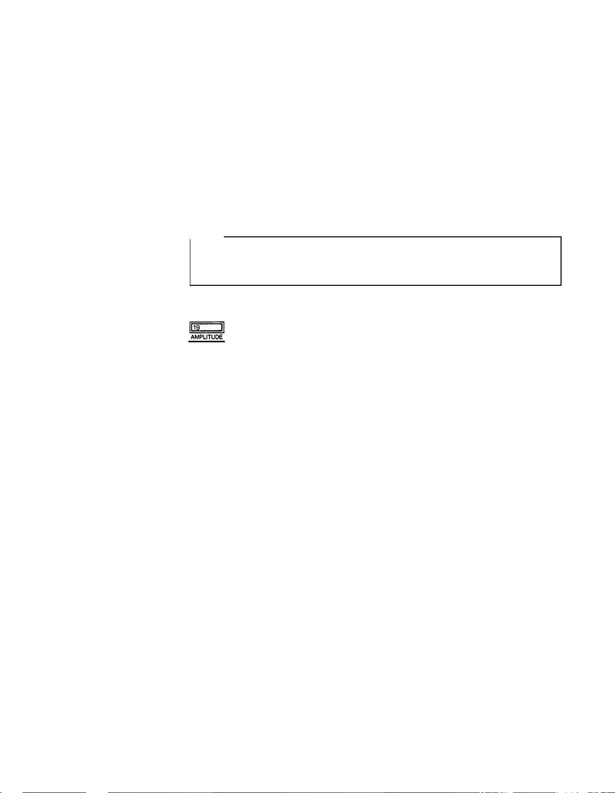
19: MODULATION WHEEL RANGE, AMPLITUDE
As you move the DX100 modulation wheel away from you, an increasing amount
of LFO modulation is applied to the selected voice. LFO modulation can be made
to modulate the amplitude (level) of specified voice elements (operators), producing
a range of tremolo or timbre modulation (wah-wah) type effects. This function
is used to set the maximum depth of amplitude modulation that can be applied
using the modulation wheel. The actual effect produced depends on the settings
of the LFO parameters, these will be discussed in
CHAPTER IV:
VOICE PROGRAMMING. Note, however, that the appropriate voice AMPLITUDE MODULATION SENSITIVITY parameter must be set to a value higher than 0 for amplitude
modulation to be effective. The voice AMPLITUDE MODULATION SENSITIVITY
parameter will also be discussed in
CHAPTER IV.
The data range is from 0 to 99. At 0, amplitude modulation is OFF, and rotating
the modulation wheel will cause no amplitude modulation to be applied to the voice.
A setting of 99 produces the greatest possible pitch modulation depth.
Data is entered using the DATA ENTRY slider or buttons. Once this function is
called, subsequent presses on the 19 button will increment the data value.
The Yamaha Breath Controller
The optional Yamaha BC-1 breath controller is a unique way of adding musical
expression as you play the DX100 keyboard. The BC-1 is held in the mouth just
like the mouthpiece of a wind instrument. Blowing harder or softer into the BC-1
mouthpiece produces a corresponding effect. The breath controller can be used
to apply varying amounts of pitch or amplitude LFO modulation, just like the
modulation wheel. In addition, it can be set up to directly affect pitch, amplitude
or timbre in response to breath pressure. Set to directly affect amplitude (EG BIAS),
for example, the breath controller can be used to apply realistic tonguing effects
to brass and other wind instrument sounds.
The four BREATH parameters listed below determine just how the breath controller
will affect the DX100’s sound. These parameters may be set individually, or combined for more complex effects.
14
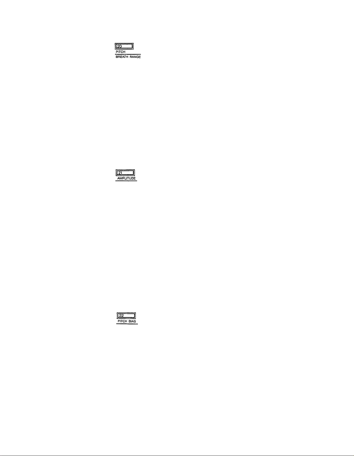
20: BREATH RANGE, PITCH
This function is used to set the maximum depth of LFO pitch modulation that can
be applied using the breath controller. The actual effect produced depends on the
settings of the LFO parameters-these will be discussed in CHAPTER IV: VOlCE
PROGRAMMING. Note, however, that the appropriate voice PITCH MODULATION SENSlTlVlTY parameter must be set to a value higher than 0 for pitch
modulation to be effective. The voice PITCH MODULATION SENSITIVITY parameter will be discussed in CHAPTER IV: VOICE PROGRAMMING.
The data range is from 0 to 99. At 0, pitch modulation is OFF, and applying breath
pressure to the breath controller will cause no pitch modulation to be applied to
the voice. A setting of 99 produces the greatest possible pitch modulation depth.
Data is entered using the DATA ENTRY slider and -1 /+1 buttons. Once this function
is called, subsequent presses on the 20 button will increment the data value.
21: BREATH RANGE, AMPLITUDE
This function is used to set the maximum depth of LFO amplitude modulation that
can be applied using the breath controller. The actual effect produced depends
on the settings of the LFO parameters–these will be discussed in
CHAPTER IV:
VOICE PROGRAMMING.Note, however, that the appropriate voice AMPLITUDE
MODULATION SENSITIVITY parameter must be set to a value higher than 0 for
amplitude modulation to be effective. The voice AMPLITUDE MODULATION
SENSITIVITY parameter will be discussed in
CHAPTER IV:
VOICE PROGRAM-
MING.
The data range is from 0 to 99. At 0, amplitude modulation is OFF, and applying
breath pressure to the breath controller will cause no amplitude modulation to be
applied to the voice. A setting of 99 produces the greatest possible pitch modulation
depth.
Data is entered using the DATA ENTRY slider or -1 /+1 buttons. Once this function
is called, subsequent presses on the 21 button will increment the data value.
22: BREATH RANGE, PITCH BIAS
This function permits breath pressure applied to the BC-1 breath controller to directly
control the pitch of the voice. In other words, the LFO has no effect. Only your
breath pressure directly affects the pitch of the voice.
The data range is from 0 to 99. At 50, pitch bias is OFF. A setting of 99 permits
a 4-octave pitch increase, and a setting of 0 permits a 4-octave pitch decrease to
be produced through the breath controller.
Data is entered using the DATA ENTRY slider and -1 /+1 buttons. Once this function
is called, subsequent presses on the 22 button increment the data value.
15
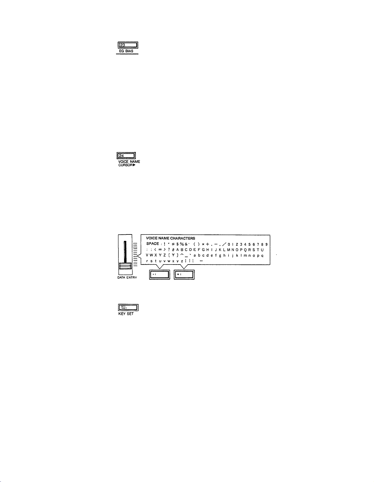
23: BREATH RANGE, EG BIAS
This function permits breath pressure applied to the BC-1 breath controller to directly
control the amplitude or timbre of the voice, according to settings of the corresponding voice parameters which will be covered in
CHAPTER IV.
The LFO has
no effect–only your breath pressure directly affects the amplitude or timbre of the
voice.
The data range is from 0 to 99. At 0, EG bias is OFF. A setting of 99 permits the
greatest amplitude or timbre variation to be produced through the breath controller.
Data is entered using the DATA ENTRY control and -1/+1 switches. Once this
function is called, subsequent presses on the 23 button increment the data value.
24: VOICE NAME
This function moves the LCD cursor from left to right, allowing you to name any
new voice or sound you have created before storing it. When button 24 is pressed,
the cursor flashes over the first letter in the name of the voice presently occupying
a space in the lNTERNAL memory. The DATA ENTRY slider or -1/+1 buttons
are used to increment or decrement the alphabetical selection (A to Z), along with
many other symbol selections, while subsequent presses on the VOICE NAME
CURSOR button move the LCD cursor to the immediate right.
KEY SET
During either of the normal DX100 play modes, pressing the KEY SHIFT button
instantly transposes the pitch of the entire DX100 keyboard up or down to a key
programmed using this function. When KEY SHlFT is engaged, the letter “K” will
appear at the left side of the LCD display until the KEY SHlFT button is pressed
again, returning the keyboard to normal pitch.
Pressing this button in the FUNCTION mode permits a shift to the desired pitch
when the KEY SHlFT button is pressed while in either of the play modes.
The transpose range for the KEY SHIFT function is plus or minus two octaves. The
data range is from -24 to +24, with 0 corresponding to standard keyboard pitch.
Each increment corresponds to a shift in pitch of one semitone-a setting of 2 would
therefore raise the pitch of the entire keyboard a whole step.
lmmediately after calling the KEY SET function, data can be entered simply by
pressing a key on the keyboard within a plus/minus two-octave range of C3 (middle
C). The pressed key then assumes the pitch of C3, and all other keys are adjusted
accordingly. Pressing the A2 key, for example, produces a setting of -3. Pressing
a key higher than C5 results in a +24 setting. This method of data entry, can only
16
4. Tuning Functions
be used once after this function is called. Subsequent changes must be made using
the DATA ENTRY slider and -1 /+1 buttons after the INTERNAL PLAY mode and
KEY SHIFT function have been entered in succession.
and KEY SHIFT function have been entered in succession.
NOTE:
The KEY SET function can not be individually programmed for each voice
This section includes a single function: MASTER TUNE ADJ.
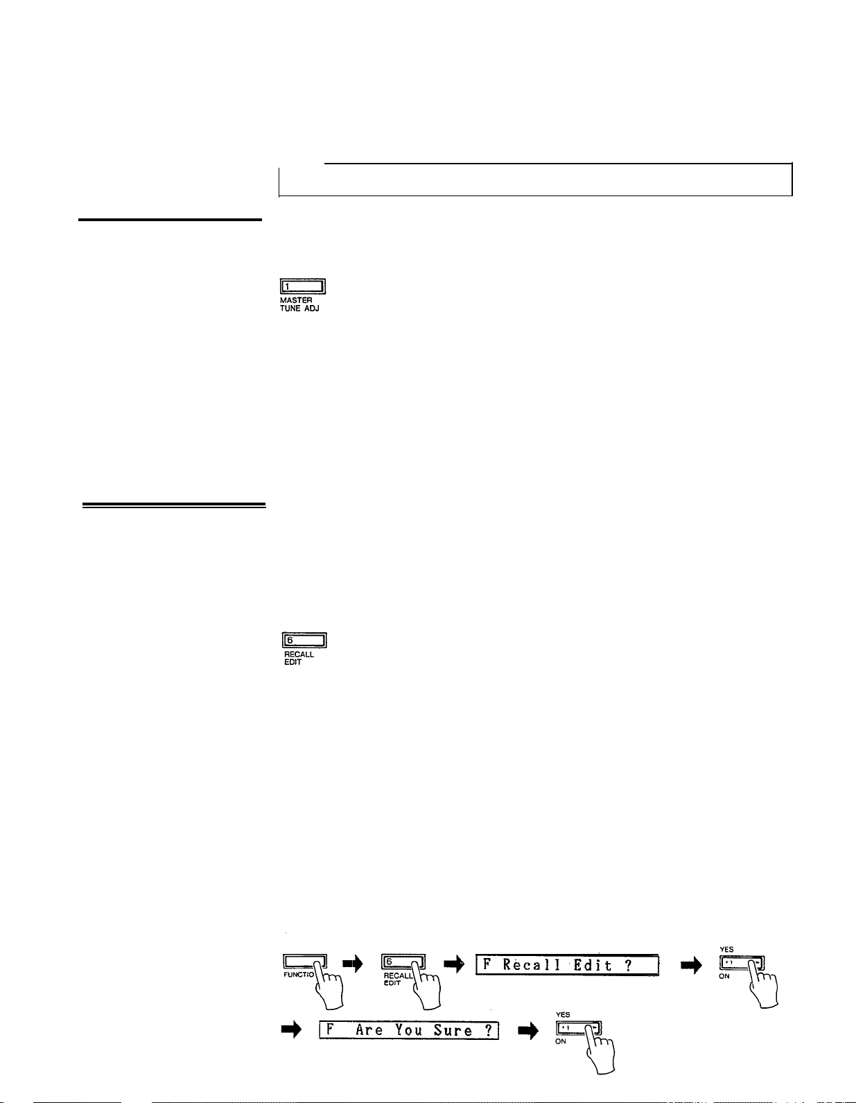
1: MASTER TUNE ADJ
This is the DX100 MASTER TUNE function. All voices are affected simultaneously.
The programmable data range is from -64 to +63. When set to 0, the pitch of the
A3 key is the standard 440 Hz. At the lowest setting of -64, the overall pitch of
the keyboard is 100 cents (1 semitone) lower than standard pitch. At the highest
setting of +63, the overall pitch of the keyboard is 100 cents higher than standard
pitch.
Use the DATA ENTRY slider or -1 /+1 buttons to enter the data for this parameter.
Once the MASTER TUNE function is called, subsequent presses on the 1 button
will increment the data value.
5. Memory
Management
Functions
The memory management functions include functions for loading voices from the
DX100’s 192–voice PRESET memory, for storing and the 24 INTERNAL memory
voices to and from cassette tape, initializing the voice memory, recalling voice data
from a special “safety” buffer memory, and turning the DX100 memory write/protect
function ON and OFF.
6: RECALL EDIT
In addition to the voice edit buffer, the DX100 has a special edit recall buffer memory
which maintains the last edited voice data. if, after editing or creating a new voice,
you inadvertently call new data into the voice edit buffer by pressing one of the
voice selector buttons before storing the edited voice data, the voice you had spent
so much time editing will be erased from the edit buffer. If only one error of this
type has been made, the edited data still resides in the Backup voice buffer and
can be recalled into the voice edit buffer using this function.
To do this, first press the FUNCTION button, then the RECALL EDIT button. The
LCD will read “Recall Edit ?” Confirm your intention to recall the data into the voice
edit buffer by pressing the +1 button. The DX100 will again respond, this time
with “Are You Sure ?” Press the +1 button again to actually execute the recall edit
function. The EDlT mode will then be automatically entered, and the voice edit
buffer will contain the data called from the Backup voice buffer. Pressing another
function button, the PLAY mode button or the EDIT mode button during the above
process will abort the recall edit function.
17
 Loading...