

Page 1
DVD PLAYER
DVD-S795/S705
SERVICE MANUAL
For U, C, B, A, G modelsFor U, C, B, A, G models
For U, C, B, A, G models
For U, C, B, A, G modelsFor U, C, B, A, G models
IMPORTANT NOTICE
This manual has been provided for the use of authorized YAMAHA Retailers and their service personnel.
It has been assumed that basic service procedures inherant to the industry, and more specifically YAMAHA Products, are
already known and understood by the users, and have therefore not been restated.
WARNING: Failure to follow appropriate service and safety procedures when servicing this product may result in personal
IMPORT ANT: The presentation or sale of this manual to any individual or firm dose not constitute authorization, certification or
The data provided is believed to be accurate and applicable to the unit(s) indicated on the cover. The reseach, engineering, and
service departments of Y AMAHA are continually striving to improve YAMAHA products. Modifications are, therefore, inevitable
and specifications are subject to change without notice or obligation to retrofit. Should any discrepancy appear to exist, please contact
the distributor’s Service Division.
WARNING: Static discharges can destroy expensive components. Dischage any static electricity your body may have accu-
IMPORT ANT: T urn the unit OFF during disassembly and parts replacement. Recheck all work before you apply power to the unit.
injury , destuction of expensive components and failure of the product to perform as specified. For these reasons,
we advise all YAMAHA product owners that any service required should be performed by an authorized
Y AMAHA Retailer or the appointed service representaive.
recognition of any applicable technical capabilities, or establish a principle-agent relationship of any form.
mulated by grounding yourself to the ground buss in the unit (heavy gauge black wires connect to this buss.)
DVD-S795/S705
100666
Printed in Japan
Page 2

CONTENTS
SECTION 1
SPECIFICATIONS ...................................................................... 1-1
LOCALE MANAGEMENT INFORMATION ................................. 1-1
TO SERVICE PERSONNEL ....................................................... 1-2
PREVENTION OF ESD TO ES DEVICES.................................. 1-3
PRECAUTION OF LASER DIODE ............................................. 1-4
HANDILNG PRECAUTIONS FOR TRAVERSE DECK............... 1-4
REAR PANELS........................................................................... 1-5
OPTICAL PICKUP SELF-DIAGNOSIS AND REPLACEMENT PROCEDURE....
SELF-DIAGNOSIS FUNCTION AND SERVICE MODE ............. 1-7
SERVICE PRECAUTIONS ......................................................... 1-9
SERVICE TOOLS AND EQUIPMENT ........................................ 1-9
OPERATING INSTRUCTIONS ................................................. 1-10
SECTION 2
ASSEMBLING AND DISASSEMBLING THE CASING AND CHECKING
C. B. A.s
1. Disassembly Procedure ....................................................... 2-1
2. Casing Parts and C.B.A. Positions ...................................... 2-2
3. Service Positions ................................................................. 2-2
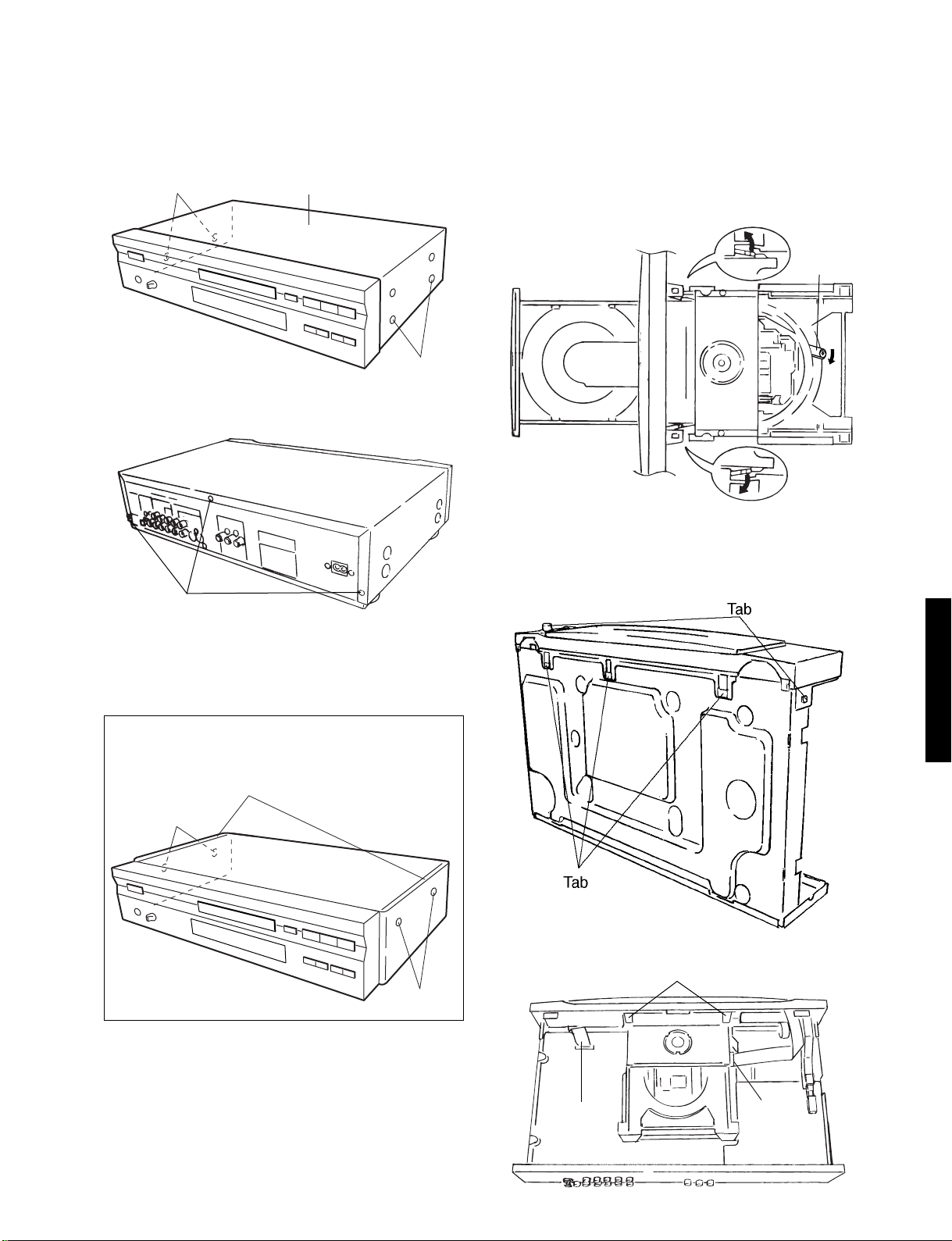
4. Disassembling the Top Cover .............................................. 2-3
5. Disassembling the Tray........................................................2-3
6. Disassembling the Front Panel ............................................ 2-3
7. Disassembling the Loading Base Unit ................................. 2-3
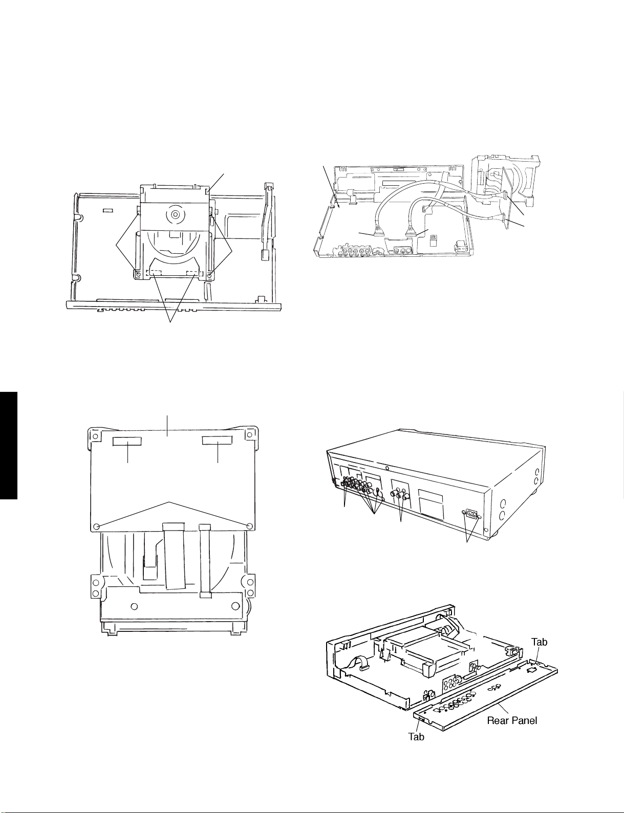
8. Checking the Module C.B.A. ................................................ 2-4
9. Disassembling the Rear Panel............................................. 2-4
10. Checking the Power Supply C.B.A. ..................................... 2-5
11. Checking the Mother C.B.A. ................................................ 2-5
12. Checking the Power Switch C.B.A. ......................................2-5
13. Checking the Front Switch C.B.A......................................... 2-5
14. Checking the Headphone C.B.A. ......................................... 2-5
ASSEMBLING AND DISASSEMBLING THE OPTICAL PICKUP
1. Handling the Optical Pickup ................................................. 2-6
2. Disassembly Procedure ....................................................... 2-6
3. Lubricating the Loading Base Unit ....................................... 2-7
DVD-S795/S705
4. Static Electricity Countermeasures ...................................... 2-8
5. Disassembling the Clamp Base Unit.................................... 2-9
6. Disassembling the Clamp Weight, Clamper Yoke,
Magnet and Clamper ...........................................................2-9
7. Disassembling the Traverse Unit ......................................... 2-9
8. Disassembling the Stepping Motor Unit ............................. 2-10
9. Disassembling the Optical Pickup Unit .............................. 2-10
10. Disassembling the Nut Unit................................................ 2-11
11. Disassembling the Sub-Shaft Preload Spring .................... 2-11
12. Assembling the Optical Pickup .......................................... 2-11
13. Disassembling the Spindle Motor Unit ............................... 2-12
14. Optical Pickup Tilt Adjustment............................................ 2-13
15. Disassembling the Intermediate Chassis ........................... 2-15
16. Disassembling the Vertical Cam and Drive Gear............... 2-15
17. Disassembling the Pulley Gear and Deceleration Gear..... 2-15
18. Disassembling the Mechanism Loading C.B.A. ................. 2-15
19. Lubricating the Optical Pickup and Peripheral parts .......... 2-16
1-6
SECTION 3
ABBREVIATIONS ....................................................................... 3-1
BLOCK DIAGRAM
1. OVERRALL BLOCK DIAGRAM ........................................... 3-3
2. SERVOBLOCK DIAGRAM................................................... 3-5
3. VIDEO BLOCK DIAGRAM ................................................... 3-7
4. AUDIO BLOCK DIAGRAM................................................... 3-9
SCHEMATIC DIAGRAM
1.
POWER SUPPLY SCHEMATIC DIAGRAM (FOR U, C MODELS) ....
2.
POWER SUPPLY SCHEMATIC DIAGRAM (FOR B, G, A MODELS)
3. ADSC (MODULE C.B.A. 1/8) SCHEMATIC DIAGRAM ..... 3-15
4. SERVO (MODULE C.B.A. 2/8) SCHEMATIC DIAGRAM... 3-17
5.
AV DECODER (MODULE C.B.A. 3/8) SCHEMA TIC DIAGRAM ...
6. VDAC (MODULE C.B.A. 4/8) SCHEMATIC DIAGRAM ..... 3-21
7. FEP (MODULE C.B.A. 5/8) SCHEMATIC DIAGRAM ........ 3-23
8. CPU (MODULE C.B.A. 6/8) SCHEMATIC DIAGRAM........ 3-25
9. CLOCK (MODULE C.B.A. 7/8) SCHEMATIC DIAGRAM ... 3-27
10. ODC (MODULE C.B.A. 8/8) SCHEMATIC DIAGRAM ....... 3-29
11.VIDEO (MODULE C.B.A. 1/5) SCHEMATIC DIAGRAM .... 3-31
12.
ADAC C (MODULE C.B.A. 2/5) SCHEMATIC DIAGRAM...
13.
AUDIO AC-3 (MODULE C.B.A. 3/5) SCHEMATIC DIAGRAM ...
14.
AUDIO OUT (MODULE C.B.A. 4/5) SCHEMATIC DIAGRAM..
15.
OPERATION (MODULE C.B.A. 5/5) SCHEMATIC DIAGRAM...
16.
VIDEO COMP SCHEMATIC DIAGRAM (FOR U, C MODELS)
17. SCART SCHEMATIC DIAGRAM (FOR B, G MODELS) .... 3-43
18.
FRONT SW/HEAD PHONE/POWER SW SCHEMATIC DIAGRAM...
CIRCUIT BOARD DIAGRAM
1. POWER SUPPLY C.B.A. (FOR U, C MODELS) ................ 3-47
2. POWER SUPPLY C.B.A. (FOR B, G, A MODELS)............ 3-49
3. MODULE C.B.A. ................................................................ 3-51
4. MOTHER C.B.A. ................................................................ 3-55
5. FRONT SW/HEAD PHONE/POWER SW C.B.A. .............. 3-57
6. SCART C.B.A. (FOR B, G MODELS). ............................... 3-59
7. VIDEO COMP C.B.A. (FOR U, C MODELS) ..................... 3-61
SECTION 4
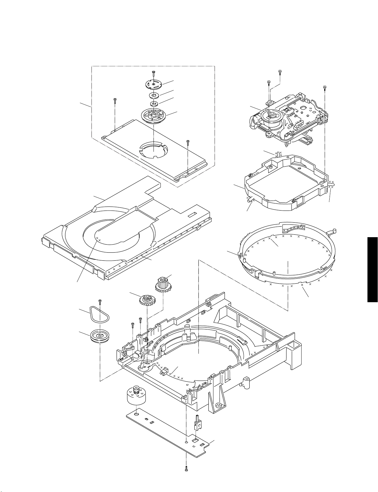
EXPLODED VIEWS & REPLACEMENT PARTS LIST
1. ELECTRICAL REPLACEMENT PARTS LIST...................... 4-1
2. Casing Parts & Mechanism Section................................... 4-18
3. Loading Mechanism Section.............................................. 4-21
4. Traverse Section................................................................ 4-23
5. REMOTE CONTROL TRANSMITTER...............................4-25
3-11
3-13
3-19
3-33
3-35
3-37
3-39
... 3-41
3-45
ELECTRICAL ADJUSTMENT
1. Video Output (Luminance Signal) Adjustment ................... 2-17
2. Video Output (Chrominance Signal) Adjustment ............... 2-17
3. Video Component Signal (CB) Output Adjustment ............ 2-18
Page 3

SECTION 1
SPECIFICATIONS
Power requlrements: For U, C models
AC 120V,60Hz
For B, A, G models
AC 220 – 240V, 50Hz
Signal system: For U, C models
NTSC
For B, A, G models
PAL 625/50, PAL 525/60, NTSC
Weight: 7.9lbs. (3.6kg)
For G:Gold model only
4.2kg
Dimensions: 17-3/16” (W) × 3-15/16” (H) × 10-3/8” (D)
[435 (W) × 100 (H) × 263 (D) mm]
For G:Gold model only
473 (W) × 100 (H) × 263 (D) mm
(excluding protrusions)
Operating temperature range:+5 to +35°C (+41 to +95°F)
Operating humidlty range: 5 to 90% (no condensation)
Discs played:
(1) DVD-VIDEO disc
5” (12cm) single-sided, single-layer
5” (12cm) single-sided, double-layer
5” (12cm) double-sided, single-layer
3” (8cm) single-sided, single-layer
3” (8cm) single-sided, double-layer
3” (8cm) double-sided, single-layer
(2) Compact disc (CD-DA, VIDEO CD)
5” (12cm) disc
3” (8cm) disc
S-video output:
For U, C models
Y output level: 1Vp-p (75Ω)(NTSC)
C output level: 0.286Vp-p (75Ω)(NTSC)
Output connector: S terminal (1 system)
For B, A, G models
Y output level: 1Vp-p (75Ω)
C output level: 0.286Vp-p (75Ω) (PAL)
For B, G models
Output connector: S terminal (1 system) / AV1
For A model
Output connector: S terminal (1 system)
Video output:
Output level: 1Vp-p (75Ω)
For U, C, A models
Output connector: Pin jack (2 systems)
For B,G models
Output connector: Pin jack (2 systems)/AV1/AV2
Power consumption: For U, C models
Compact video output:
Output level: 2 Vrms (1kHz, 0dB)
Output connector: Pin jack
5.1ch mixed output: 1 system (2ch)
5.1ch discrete output: 1 system (5.1ch)
Audio signal output characteristics:
(1) Frequency response:
DVD (linear audio):
2Hz to 22kHz (48kHz sampling)
2Hz to 44kHz (96kHz sampling)
CD audio:
2Hz to 20kHz (EIAJ)
(2) S/N ratio:
CD audio: 115dB (EIAJ)
(3) Dynamic range:
DVD (linear audio): 103dB
CD audio: 100dB (EIAJ)
(4) Total harmonic distortion:
CD audio: 0.002% (EIAJ)
Digital audio output:
Optical digital output: Optical connector
Coaxial digital output: Pin jack
Pick up: Wave length: 655nm
Laser power: CLASS
Specifications are subject to change without notice.
Weight and dimensions are approximate.
U ........ U.S.A. model G ........ European model
C ........ Canadial model B ........ United Kindom model
A ........ Australlan model
Manufactured under license from Dolby Laboratories Licensing Corporation. “Dolby” and the double-D symbol are
trademarks of Dolby Laboratories Licensing Corporation.
19W
(approx. 1W when set to the standly
mode)
For B, G models
20W (approx. 2.5W when set to the standby
mode)
For A models
19W (approx. 2W when set to the standby mode)
For U, C models only
Y output level: 1Vp-p (75Ω), green
CB output level: 0.7Vp-p (75Ω), blue
CR output level: 0.7Vp-p (75Ω), red
Output connector: Pin jack
Audio output:
II
DVD-S795/S705
LOCALE MANAGEMENT INFORMATION
Locale Management Information: This DVD player is designed and manufactured to respond to the Locale
Management information that is recorded on a DVD disc. If the Locale number described on the DVD disc
does not correspond to the Locale number of this DVD player, this DVD player cannot play this disc.
(See page1-3, REGION CODE.)
This product incorporates copyright protection technology that is protected by method claims of certain
U.S. patents and other intellectual property rights owned by Macrovision Corpoation and other rights
owners. Use of this copyright protection techology must be authorized by Macrovision Corporation,
and is intended for home and other limited viewing uses only unless otherwise authorized by Macrovision
Corporation. Reverse engineering or disassembly is prohibited.
1 - 1
Page 4
TO SERVICE PERSONNEL
1. Critical Components Information.
Components having special characteristics are marked
and must be replaced with parts having specifications equal
to those originally installed.
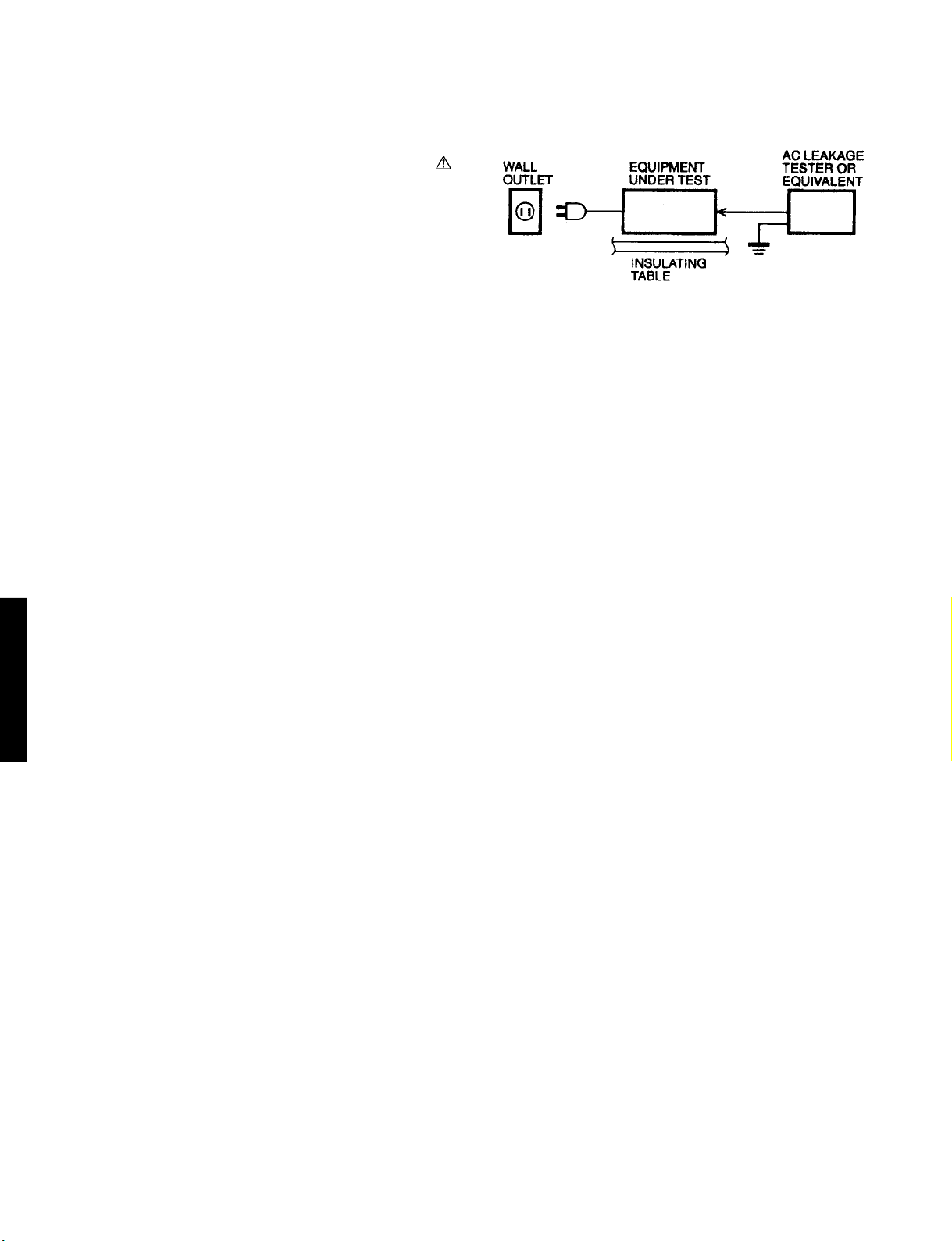
2. Leakage Current Measurement (For 120V Models Only).
When service has been completed, it is imperative to verify
that all exposed conductive surfaces are properly insulated
from supply circuits.
• Meter impedance should be equivalent to 1500 ohm shunted
by 0.15mF.
• Leakage current must not exceed 0.5mA.
• Be sure to test for leakage with the AC plug in both polarites.
CAUTION: USE OF CONTROLS OR ADJUSTMENTS OR PERFORMANCE OF PROCEDURES OTHER THAN
THOSE SPECIFIED HEREIN MAY RESULT IN HAZARDOUS RADIATION EXPOSURE.
THE COMAPCT DISC PLAYER SHOULD NOT BE ADJUSTED OR REPAIRED BY ANYONE EXCEPT PROPERLY
QUALIFIED SERVICE PERSONNEL.
PROTECTION OF EYES FROM LASER BEAM DURING SERVICING
This set employs a laser. Therefore, be sure to carefully
follow the instructions below when servicing.
1. Pick up
• Wave length : 655nm
• Laser power : CLASS
WARNING: CHEMICAL CONTENT NOTICE!
DVD-S795/S705
The solder used in the production of this product contains LEAD. In addition, other electrical/electronic
and/or plastic (where applicable) components may also contain traces of chemicals found by the
California Health and Welfare Agency (and possibly other entities) to cause cancer and/or birth defects
or other reproductive harms.
DO NOT PLACE SOLDER, ELECTRICAL/ELECTRONIC OR PLASTIC COMPONENTS IN YOUR MOUTH
FOR ANY REASON WHATSOEVER!
Avoid prolonged, unprotected contact between solder and your skin! When soldering, do not inhale
solder fumes or expose eyes to solder/flux vapor!
If you come in contact with solder or components located inside the enclosure of this product, wash your
hands bofore handing food.
2. When checking the laser diode emission, keep your eyes
more than 30 cm away from the objective lens.
II
1 - 2
Page 5
PREVENTION OF ELECTRO STATIC DISCHARGE (ESD) TO
ELECTROSTATICALLY SENSITIVE (ES) DEVICES
Some semiconductor (solid state) devices can be damaged easily by static electricity. Such components commonly are called Electrostatically
Sensitive (ES) Devices. Examples of typical ES devices are integrated circuits and some field-effect transistors and semiconductor “chip”
components. The following techniques be used to help reduce the incidence of component damage caused by electro static discharge
(ESD).
1. Immediately before handling any semiconductor component or semiconductor-equipped assembly, drain off any ESD on your body by touching
a known earth ground. Alternatively, obtain and wear a commercially available discharging ESD wrist strap, which should be removed for
potential shock reasons prior to applying power to the unit under test.
2. After removing an electrical assembly equipped with ES devices, place the assembly on a conductive surface suck as alminum foil, to prevent
electrostatic charge buildup or exposure of the assembly.
3. Use only a grounded-tip soldering iron to solder or unsolder ES devices.
4. Use only a anti-static solder removal device. Some solder removal devices not classified as “anti-static (ESD protected)” can generate
electrical charge sufficient to damage ES devices.
5. Do not use freon-propelled chemicals. These can generate electrical charges sufficient to damage ES devices.
6. Do not remove a replacement ES device from its protective package until immediately before you are ready to install it. (Most replacement ES
devices are packaged with leads electrically shorted together by conductive foam, alminum foil or comparable conductive material).
7. Immediately before removing the protective material from the leads of a replacement ES divice, touch the protective material to the chassis or
circuit assembly into which the device will be installed.
CAUTION: Be sure no power is applied to the chassis or circuit, and observe all other safety precautions.
8. Minimize bodily motions when handling unpackaged replacement ES devices. (Otherwise hamless motion such as the brushing together of
your clothes fabric or the lifting of your foot from a carpeted floor can generate static electricity (ESD) sufficient to damage an ES device).
IMPORTANT SAFETY NOTICE
There are special components used in this equipment which are imporant for safety.
These parts are marked by in the schematic diagrams, exploded views and replacement parts list. It is
essential that these critical parts should be replaced with manufacturer’s specified parts to prevent shock, fire, or
other hazards. Do not modify the original design without permission of manufacturer.
DVD-S795/S705
REGION CODE
5
1
2
6
2
3
4
2
5
4
5
1 - 3
Page 6
PRECAUTION OF LASER DIODE
CAUTION:
This unit utilizes a class I laser. Invisible laser radiation is emitted from the optical pickup lens when the
unit is truned on:
1. Do not look directly into the pickup lens.
2. Do not use optical instruments to look at the pickup lens.
3. Do not adjust the preset variable resistor on the optical pickup.
4. Do not disassemble the optical pickup unit.
5. If the optical pickup is replaced, use the manufactures specified replacement pickup only.
6. Use of control or adjustment or performance of procedures other than those specified herin may result in hazardous
radiation exposure.
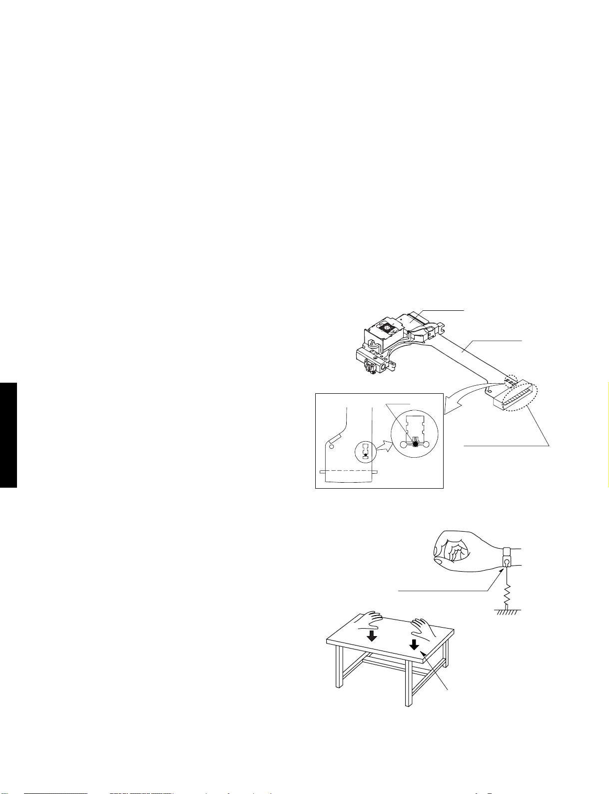
HANDLING PRECAUTIONS FOR TRAVERSE DECK
The laser diode in the optical pickup may break down due to
potentical diference caused by static electricity of clothes or
human body.
So be careful of electrostatic break down during repair of the
optical pickup.
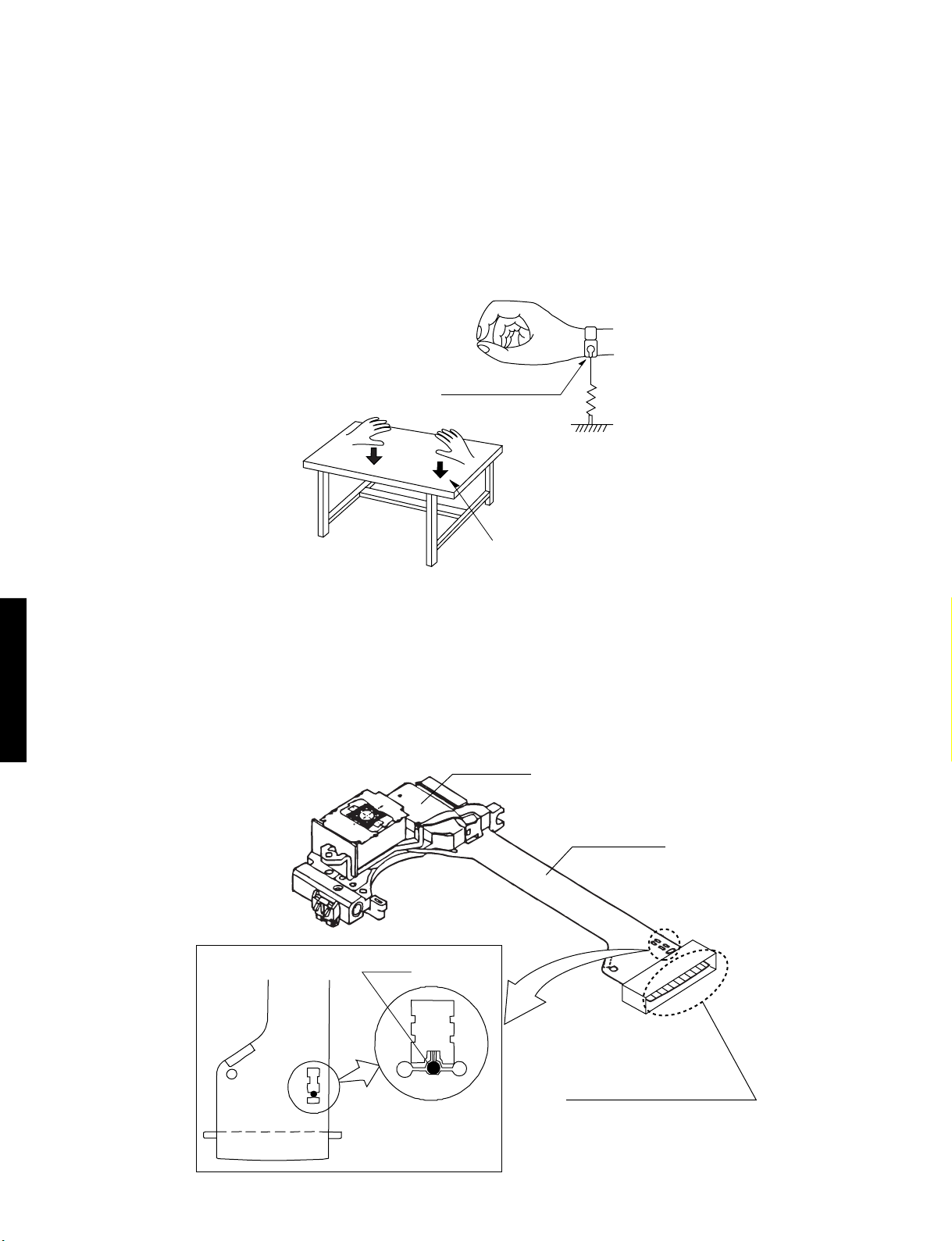
Handling of optical pickup
1. Do not subject the optical pickup to static electricity
as it is extremely sensitive to electrical shock.
2. To prevent the breakdown of the laser diode,
an antistatic shorting pin is inserted into the
flexible board (FPC Board).
When removing or connecting the short pin,
finish the job in as short times as possible.
3. Be careful not to apply excessive stress to the
flexible board (FPC Board).
4. Do not turn the variable resistor (Laser power adjustment).
DVD-S795/S705
It has already been adjusted.
Pickup unit
Solder
(Magnified view)
Flexible Cable
Use a clip or other item
to ground the unit.
Grounding for electrostatic breakdown prevention
1. Human body grounding.
Use the antistatic wrist strap to discharge the static
electricity from your body.
2. Work table grounding.
Put a conductive material (sheet) or steel on the area
where the optical pickup is placed and ground the sheet.
Caution:
The static electricity of your clothes will not be grounded
through the wrist strap. So take care not to let your clothes
touch the optical pickup.
1 - 4
Wrist strap
(Anti-static bracelet)
1M
Iron plate or some metals
to conduct electricity
Page 7
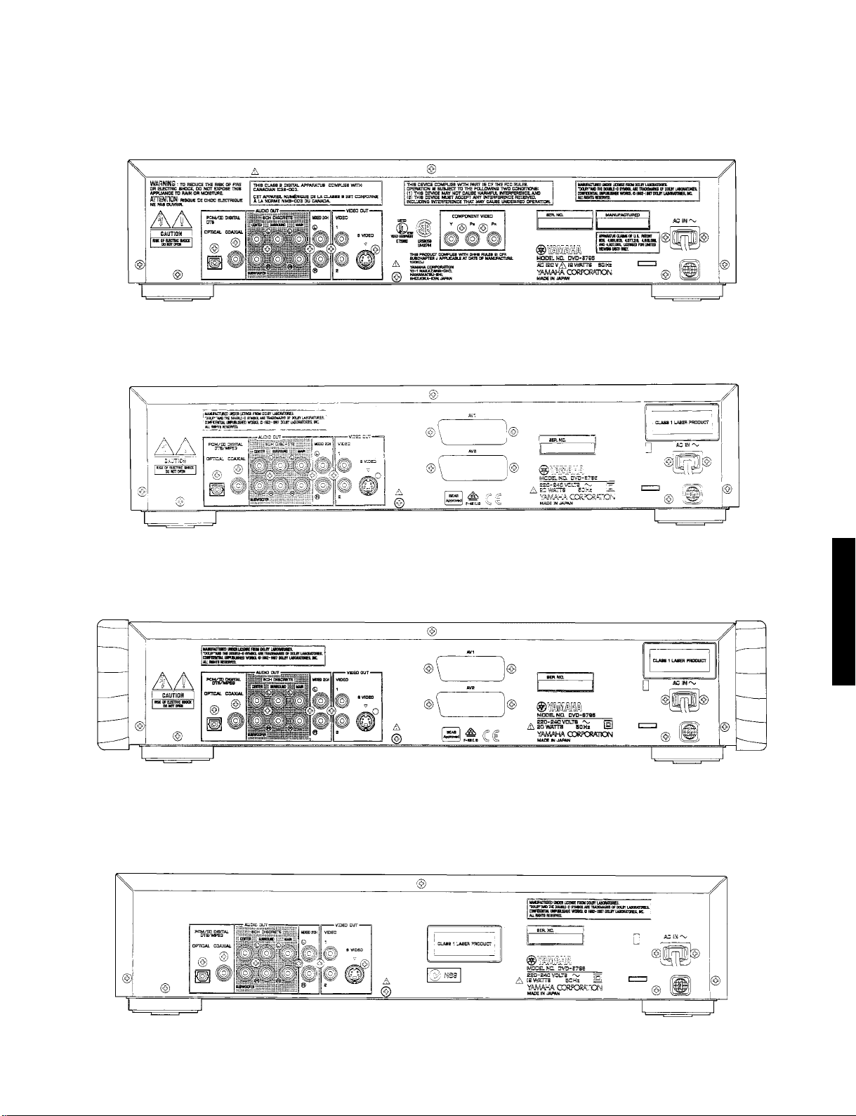
REAR PANELS
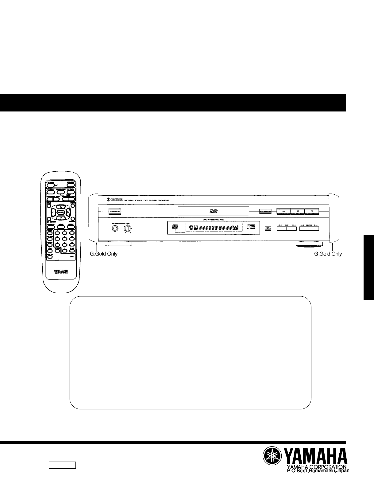
▼ U,C models (DVD-S795/S705)
▼ B, G models
▼ G model (Gold)
▼ A model
DVD-S795/S705
1 - 5
Page 8
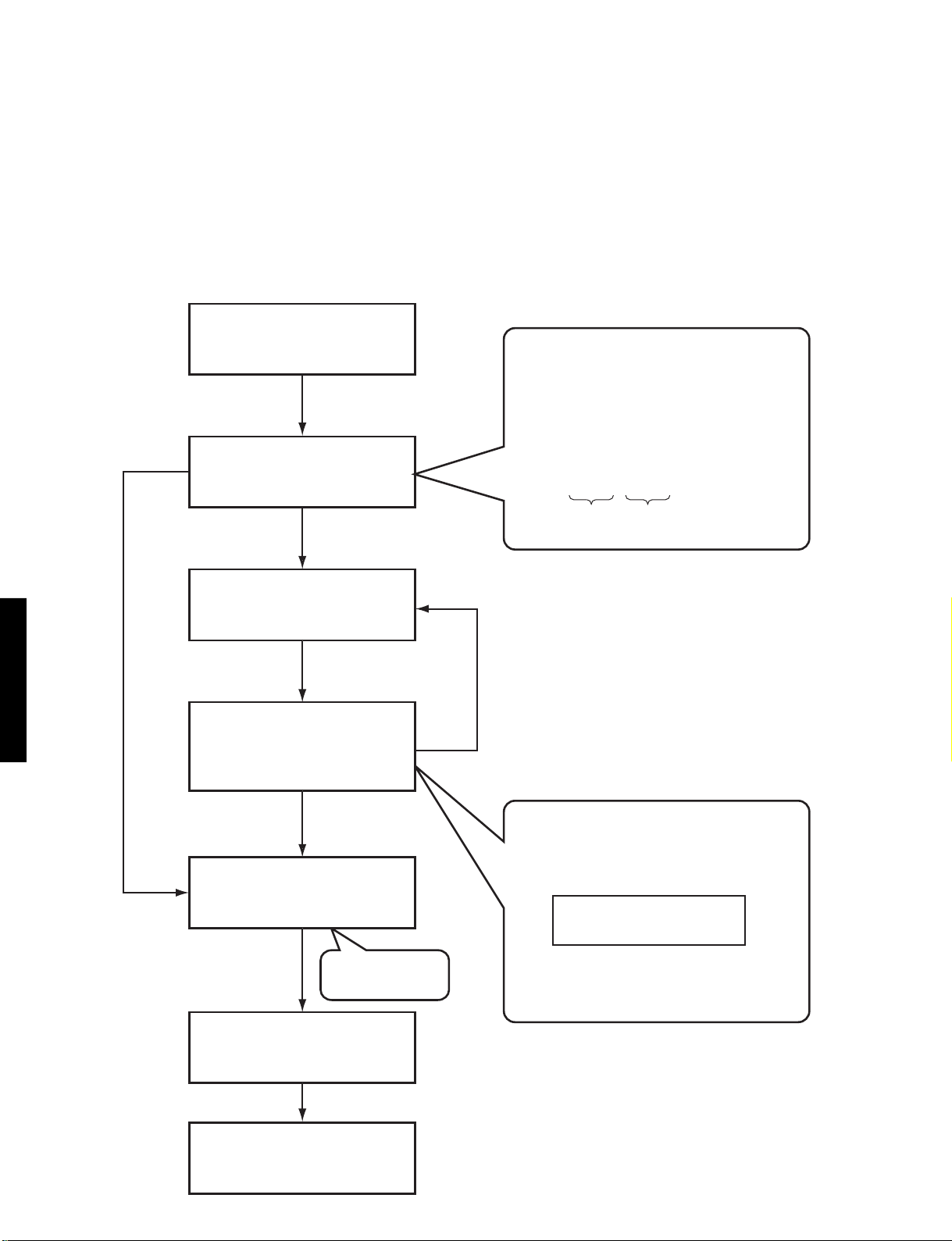
OPTICAL PICKUP SELF-DIAGNOSIS AND REPLACEMENT PROCEDURE
The optical pickup self-diagnosis function and tilt adjustment check function have been newly added to this player. When repairing, use the following procedure for effective Self-diagnosis and tilt adjustment.
Be sure to use the self-diagnosis function before replacing the optical pickup when “NO DISC” is displayed. As a guideline, you
should replace the optical pickup when the value of the laser drive current is more than 50.
Note
Press the power button to turn on the power, and check the value before the unit warms up (within three minutes).
• Use the self diagnosis function below
when NO DISC is displayed or unit
doesn't read a disc, before replacing
the OPU.
"NO DISC" is displayed,
unit does not play smoothly, etc.
• Use the optical pickup self-diagnosis function.
Method: With no disc in the player.
• Press the "DISPLAY" button on the
remote control unit while pressing the
"STILL/PAUSE" and "OPEN/CLOSE"
button on the player.
Value is
50 or less
DVD-S795/S705
Check the laser drive current.
Value is
more than 50
Replace the optical pickup
(Refer to Assembling and
Disassembling the Optical
Pickup, page 2-1.)
Checkthelaserdrive
currentafterreplacement.
• Writethepresentvalueinto
theunitifitis40orless.
Do the optical pickup
tilt adjustment.
(Refer to Optical Pickup
Tilt Adjustment, page 2-13.)
Display content
LD○○○ ○○○
Factory
preset value
Replace with a new optical pickup if the present
value is more than 40.
Cause:
Damage due to static electricity during replacement.
Method: With no disc in the player.
• Press the "DISPLAY" button on the
remote control unit while pressing the
"PAUSE" and "OPEN/CLOSE"
button on the player.
• Write the present value into
the played if it is 40 or less.
Present value
Use the tilt
adjustment
check function.
Initialize the player.
Press Pause and and
Open/Close buttons on unit
simultaneously.
End
(Refer to Handling After
Completing Repairs, page 1-9.)
▲
▲
Writing method:
• Press the "PAUSE" button on the remote
control unit while pressing the "PAUSE" and
"OPEN/CLOSE" button on the player.
1 - 6
Page 9
SELF-DIAGNOSIS FUNCTION AND SERVICE MODES
1. Service Mode Table
The service mode can be activated by pressing various button combinations on the player and remote control unit.
Player buttons
PAUSE
+
OPEN/CLOSE
STILL/PAUSE
SKIP/SEARCH<<
OPEN/CLOSE
Remote control unit button
0
5
6
7
9
DISPLAY
STILL/PAUSE
Displaying the UHF display F_ _ _
Tiltadjustment
Checkingtheregionnumbersandbroadcastsystem
Checkingtheprogramversion
LightingConfirmationFanctionofDisplayTube
Checkingthelaserdrivecurrent
Writing the laser drive current value after replacing
the optical pickup (do not use for anything other than
optical pickup replacement)
Initializing the DVD player
(restoring factory preset settings)
Use when replaceing a microprocessor, microprocessor
peripheral parts, or C. B. A.
Application
Note
Refer to Self-Diagnosis Function
(UHF Display)
Refer to Optical Pickup Tilt
Adjustment, in page 2-13.
Check the IC6302
FLASH ROM program.
Refer to Optical Pickup SelfDiagnosis and Replacement,
in page 1-6.
Procedure.
Refer to Initializing the DVD
Player, in page 1-9.
,in page 1-7.
2. Self-Diagnosis Function (UHF Display)
This unit incorporates a convenient self-diagnosis function for use in troubleshooting.
Display method Display
U11
H01
H02
H03
H04
H05
H06
F0**
F1**
F2**
F3**
F4**
F5**
F6**
F7**
F8**
Service numbers displayed
during use.
Press the "0" button on the
remote control unit while pressing
the "STILL/PAUSE" and
"OPEN/CLOSE" button on the
player.
Focus error
Tray loading error
Spindle servo error
Traverse error
Tracking servo error
Seek error
Power supply error
Disc format error
Disc code error
Decoder LSI error
SDRAM error
IIC BUS error
DSC
ECC error
Microprocessor error
Microprocessor error
Diagnosis
Checkpoints
IC2001,IC2511,IC5201,pickup
IC2001,IC2511 loading motor
Spindle motor, IC2501,IC2001
Stepping motor,IC2511,IC2001
IC2001,IC2501,IC5201,pickup,disc
Stepping motor,IC2511,IC2001
IC1021,IC1121,IC1151,IC6001
If this type of error occurs,refer to
Examples of Repairs Using Error
Codes, in page 1-8.
DVD-S795/S705
1 - 7
Page 10

3. Examples of Repairs Using Error Code
Refer to this section when carrying out repairs.
Error display
F0**
F103
F4FF
F500
F501
F502
F504
F505
F506
F600
F601
F602
F603
F610
F611
F612
F620
F621
F700
F701
F702
F880
F890
F891
F8A0
F893
F894
Disc, IC7001
Disc, IC7001
IC6001
Optical pickup, IC2001, IC5201, IC2511, IC2501
IC2001, IC6201
IC2501, IC2511, IC2001, IC5202
IC5202, IC2001
Disc, IC2501, IC2511, IC5202, IC2001
Disc, Optical pickup, IC2001
Disc, IC7001, IC5202, IC2001
Disc, IC7001
Disc, IC5202, IC2001
Disc, IC5202, IC2001
IC7001
IC7001, IC5202, IC2001
IC7001, IC15202,IC2001
Laser drive circuit
Laser drive circuit
IC6201
IC6201
IC6201
IC6201
IC6201
IC6201
IC6201
IC6302
IC6303
Malfunction example
4. Sales Demonstration Lock Function
This function prevents discs from being lost when the unit is used for sales demonstrations, by disabling the disc eject function.
DVD-S795/S705
“LOCKED” is displayed on the unit, and ordinary operation is disabled.
4-1. Setting Method
The sales demonstration lock function is set by simultaneously pressing the “POWER” button of DVD Player on the remote
control unit and the “STOP” button on the main unit. (“LOCKED” is displayed when the lock function is enagaged.)
4-2. Release Method
The function can be released using the same procedure as for setting. If the remote control unit is not at hand, the function can be
released by using the same method as for player initialization (pressing the “PAUSE”, “SKIP/SEARCH<<” and “OPEN/CLOSE”
buttons simultaneously).
1 - 8
Page 11

SERVICE PRECAUTIONS
1. Initializing the DVD Player
Initialize the DVD player whenever you replace a microprocessor, microprocessor peripheral parts, module C.B.A or mother C.B.A.
1-1. Precautions
The customer settings will return to factory preset settings when the player is initialized. Make a note of the settings and reset
them after initializing.
• When resetting, see the Initial Setting in the Operating Instructions.
1-2. Initialization Method
The player will be initialized (return to the factory preset condition) when you press the “PAUSE”, “SKIP/SERCH<<“ and “OPEN/CLOSE”
buttons simultaneously. When the DVD player is initialized, “All Clear” appears on screen, it also displays “INITIALIZED”.
2. Handling After Completing Repairs
Use the following procedure to secure the traverse unit in the standby position.
2-1. Method
With the power turned on:
1. Press the “OPEN/CLOSE” button to close the tray.
2. Press the “POWER” button to turn off the power.
3. Disconnect the power plug from the outlet.
2-2. Precautions
Do not disconnect the power plug from the outlet with the tray still open, then close the tray manually. If you were to do so, the
traverse unit would not go to the upper (standby) position, and the player could not be transported.
DVD-S795/S705
SERVICE TOOLS AND EQUIPMENT
1. Service Tools and Equipment Table
Application
General
Tilt adjustment
Inspection
Others
Confirmation
Electrical adjustment
General
Static electricity countermeasures
DVD test disc
Hex wrench
Adjustment table
Extension cables (Power supply C.B.A. to mother C.B.A.)
Extension cable (module C.B.A. to mother C.B.A.)
Screw lock
Grease
Lubricant
Grease
CD test disc
VCD test disc
Oscilloscope
Probe
AV calbe
TV monitor
General tools (Screw driver etc.)
Soldering iron (with ESD countermeasure)
Anti-static wrist strap
Conductive material (conductive sheet)
Name Number
DVDT-S15 (AX07320) or DVDT-S01 (TX946080)
JZS0100 (TX946380)
JGS0099 (TX946360)
JGS0098 (TX946370) × 2
RZZ0L01 (TX946400)
JGS0091 (TX946260)
JGS0092 (TX946270)
JZS0648 (TX946410)
JGS0101 (TX946390)
SZZP1054C (TX946090)
PVCD_K06 (TX946090)
VJA0658 (MX605190)
2. Storing and Handling Test Discs
Surface precision is vital for DVD test discs. Be sure to store and handle them carefully.
1. Do not place discs directly onto the workbench, etc., after use.
2. Handle discs carefully in order to maintain their flatness.
Place them into their case after use and store them verically . Store discs in a cool place where they are not exposed to direct
sunlight or air from air conditioners.
3. Accurate adjustment will not be possible if the disc is warped from being placed on a surface made of glass, etc. If this
happens, use a new test disc to make optical adjustments.
4. If adjustment is done using a warped disc, the adjustment will be incorrect and some discs will not be playable.
1 - 9
Page 12
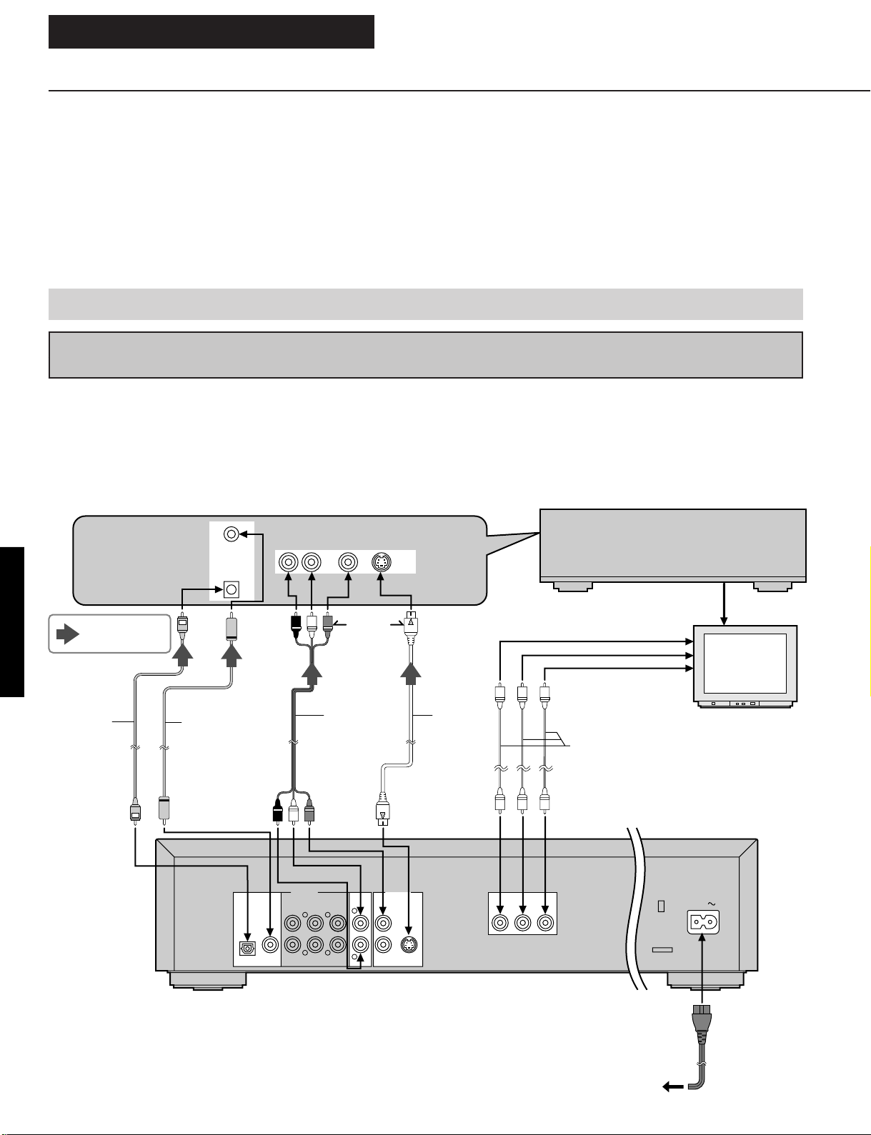
OPERATING INSTRUCTIONS
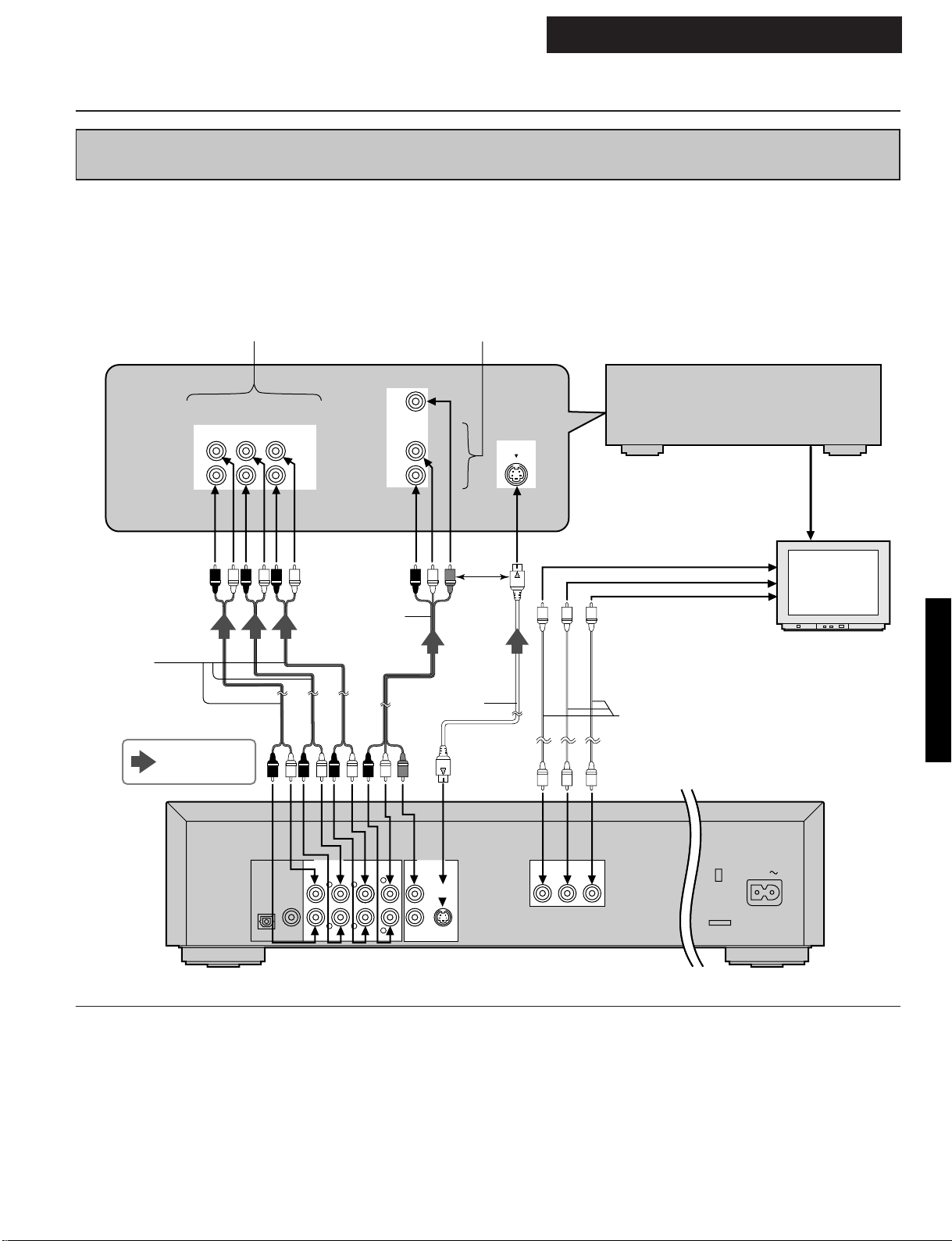
Connection
•Ensure that this player and other equipment to be connected are set to the standby mode or off, and disconnect the AC cord, bef ore commencing
connection.
•Do not block ventilation holes of any of the equipment and arrange them so that air can circulate freely.
•Read through the instructions before connecting other equipment.
•Ensure that you observe the color coding when connecting audio and video cables.
•Select the appropriate screen type at the initial setting "6 TV Aspect" according to your TV set [4:3/16:9 and Standard (Direct View TV)/CRT Projector/
LCD Projector/Projection TV].
Notes:
•If the DVD/Video CD/CD player is connected to the TV through a video cassette recorder, the picture may not be played back norm ally with some
DVDs.
•When playing some DVD discs, TV volume level may be lower than from some other sources, adjust the TV volume to your desired level.
•When the DVD/Video CD/CD player is connected to the TV set through the component video output connectors, the ON SCREEN informations from
the amplifier will not show on the TV screen. To show them, select the input position which is connected to the amplifier on the TV set.
Do not place the player on amplifiers or other equipment which may become hot.
Connecting to an AV amplifier containing Dolby Digital or dts (digital theater systems)
decoder
When DVDs recorded in Dolby Digital or dts are played, Dolby Digital bitstream or dts bitstream is output from the player’s OPTICAL
digital audio output connector or COAXIAL digital audio output connector. When the player is connected to a Dolby Digital decoder or
dts decoder, you can enjoy theater-quality audio in your home. [An optical digital audio cable or coaxial digital audio cable (both
optional) is required when an optional Dolby Digital decoder or dts decoder is used.]
Note:
•
When connecting an AV amplifier which contains dts decoder, be sure to select "Bitstream" at "3 dts" of the initial setting "7 Digital
Audio Output". ("Off" is selected at the factory preset.) If "Off" is selected, dts bitstream is not output from the digital audio output
connector.
Direction of
signal flow
Optical
DVD-S795/S705
digital
audio cable
(optional)
or
COAXIAL
DVD/LD
OPTICAL
Coaxial digital
audio cable
(optional)
PCM/U DIGITAL
DTS
OPTICAL
AUDIO SIGNAL
R L VIDEO S-VIDEO
VIDEO SIGNAL
DVD/
LD
Video/audio
cable
(supplied)
AUDIO OUT
6CH DISCRETE
COAXIAL
CENTER SURROUND
MAIN
L
or
MIXED 2CH
L
VIDEO OUT
VIDEO
1
DVD/
LD
S VIDEO
S video
cable
(optional)
AV amplifier with
Dolby Digital/dts
decoder (optional)
To component video input
connectors (Y, CB, CR)
Video cable (optional)
COMPONENT VIDEO
YCBC
R
TV set (optional)
DVD/Video CD/CD player
AC IN
SUBWOOFER
RLR
R
2
AC cord (supplied)
To AC outlet
1 - 10
Page 13
Connection
OPERATING INSTRUCTIONS
Connecting to an AV amplifier which does not contain Dolby Digital or dts (digital theater
systems) decoder
This DVD/Video CD/CD player contains a Dolby Digital decoder. This enables the playback of DVDs recorded in Dolby Digital Surround or Linear PCM without the need for an optional decoder with Dolby Digital or Linear PCM processing. When the DVD/Video CD/
CD player is connected to an AV amplifier with 5.1ch input connectors, you can enjoy theater-quality audio in your home when playing
discs recorded in Dolby Digital Surround or Linear PCM.
In the case of the AV amplifier
with 5.1ch input connectors
6CH DISCRETE INPUT DVD/LD
CENTER
SUB
WOOFER
Audio cord
(optional)
Direction of
signal flow
SURROUND
MAIN
L
R
Video/audio
cord
(supplied)
In the case of the AV amplifier without
5.1ch input connectors
VIDEO SIGNAL
AUDIO SIGNAL
L
R
DVD/LD
S-VIDEO
or
S video cord
(optional)
AV amplifier without
Dolby Digital/dts
decoder (optional)
To component video input
connectors (Y, CB, CR)
DVD-S795/S705
TV set (optional)
Video cable
(optional)
DVD/Video CD/CD player
AUDIO OUT
COAXIAL
6CH DISCRETE
CENTER SURROUND
L
RLR
SUBWOOFER
PCM/U DIGITAL
DTS
OPTICAL
Notes:
•After connection is made, set the ì8 Speaker Settingî (such
as Yes/No and Large/Small) according to your speaker system.
•If the surround speakers are set to ìNoî at the ì8 Speaker
Settingî (see page 40), the discs recorded in Linear PCM will
be played back only in 2 channels even when the center
speaker is connected as well as the front speakers.
VIDEO OUT
MIXED 2CH
VIDEO
MAIN
1
L
R
S VIDEO
2
COMPONENT VIDEO
YCBC
R
AC IN
•DVDs recorded in Linear PCM/96 kHz sampling in which
ìCenter Speakerî is contained will also be played back only
in 2 channels.
•If the player is connected to the AV amplifier as shown
above, audio recorded in dts will not be output. To enjoy dts
sound, it is necessary to connect the player.
1 - 11
Page 14
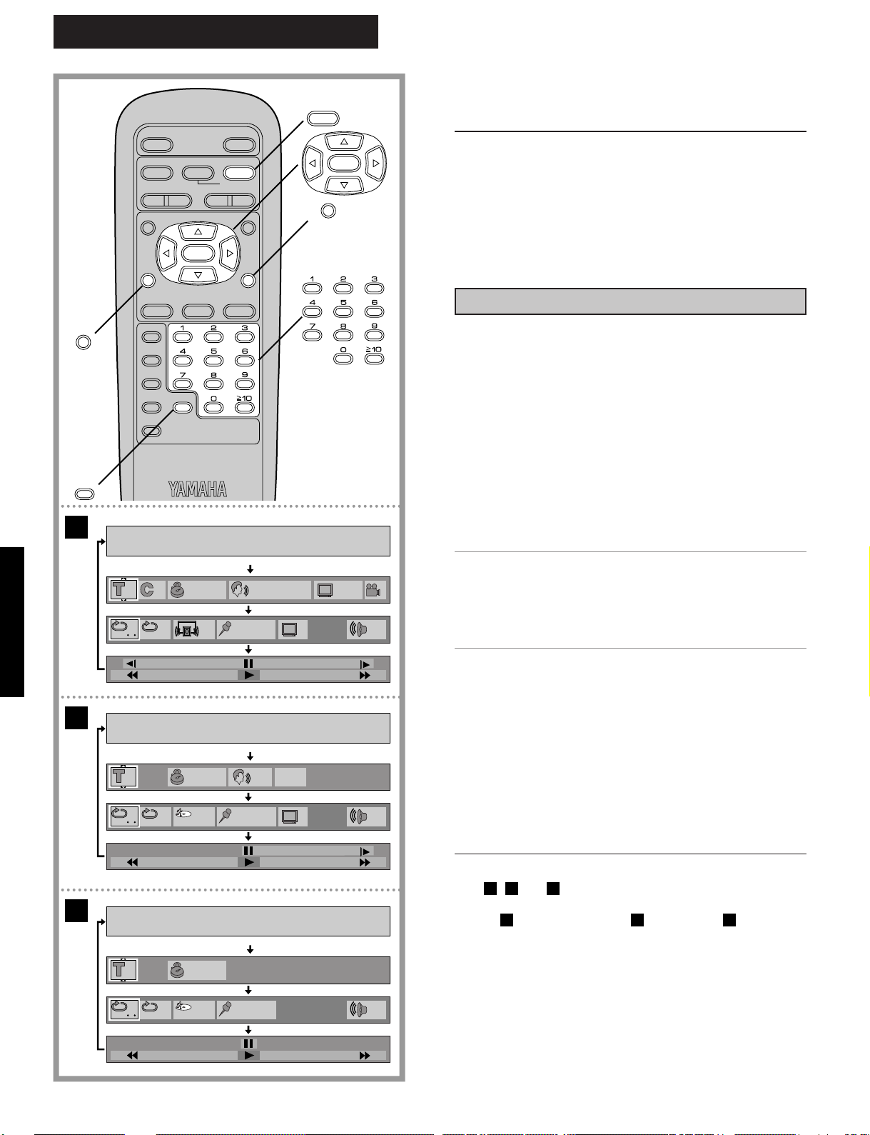
OPERATING INSTRUCTIONS
ON SCREEN
CLEAR
A
STILL/PAUSE
SELECT
OPEN/CLOSE
D
PLAY
SLOW/
G
SEARCH
ANGLEAUDIO
DVD
MENU
POWER
* / I
@
STOP
g
H
SKIP IF
TITLE
ON SCREEN RETURN
SUBTITLE
MARKER
PLAY MODE
REPEAT
A-B CLEAR
SET UP
D
PLAY
RETURN
SELECT
General information about OnScreen Menu Icons
This player features On-Screen Menu Icons providing various
functions. A "banner" will be displayed on the TV monitor by
pressing the ON SCREEN button on the remote control.
Operating the cursor buttons/SELECT button on the remote
control will show disc information (title/chapter/track number,
elapsed playing time, audio/subtitle language, and angle) and
player information (repeat play, play mode, marker, etc.).
Some icons allow the settings to be changed.
Common procedures
1
Press ON SCREEN during play or in the
stop mode.
Each time this button is pressed, the TV monitor changes
as shown below.
→ On-Screen Menu Icons are not displayed
|
|| On-Screen Menu Icons for selecting disc information
|
| On-Screen Menu Icons for selecting player information
|
•Some functions cannot be accessed from the stop
mode.
↓
↓
↓
Shuttle screen
p
100
DVD-S795/S705
B
p
40
C
p
50
1 1:56:37 1
1
OFF
1
OFF
1
OFF
OFF
3:37
PRG
3:37
PRG
ENG
L R
LPCM
b
PBC
OFF
N0
F
ON
ENG
µ
dB
dB
µ
dB
µ
2
Press the cursor buttons (
148k 16
the preferred item.
▲
, ) to select
▲
•The currently selected item is indicated by the yellow
frame on the On-Screen Menu Icons.
0N
3
100
Press the cursor buttons (
▲, ▼
) to select
the preferred setting.
•For some functions, the setting will be registered imme-
diately; for others, SELECT or PLAY must be pressed.
•When numbers are displayed (e.g. title No.), the numeric
buttons are also effective for setting instead of the cursor
buttons (
meric buttons, press SELECT to register the setting.
Press RETURN or CLEAR to clear the On-Screen Menu
Icons.
40
Examples of On-Screen Menu Icons
(See , and for detailed illustration.)
A B C
(The screens may differ depending on the disc contents.)
•DVD ( ) •Video CD ( ) •CD ( )
For your reference:
•Depending on the type of DVD software and a TV with auto-
matic picture zoom function enabled, the On-Screen Menu
Icons may not be displayed or only partially displayed on the
0
TV screen.
In this case, change the position of the On-Screen Menu
50
Icons in "4 On-Screen Messages" of the initial settings.
•The color (blue, violet or green) of the On-Screen Menu
Icons can be changed.
▲, ▼
). When numbers are entered by the nu-
A B C
1 - 12
Page 15
Detailed descriptions of each On-Screen Menu Icon
OPERATING INSTRUCTIONS
Screen for disc information (For DVD)
Title No. Change the title No. by using the cursor buttons (▲, ▼) or the numeric buttons and press SELECT.
1 1:56:37
Audio soundtrack
language No.
Audio soundtrack
language
Chapter No.
Elapsed playing time
(hour: minute: second)
1 1
Change the No. by using the
cursor buttons (▲, ▼) or the
numeric buttons.
ENG: English POR: Portuguese
FRA: French RUS Russian
DEU: German JPN: Japanese
ITA: Italian CHI: Chinese
ESP: Spanish KOR:Korean
NLD: Dutch MAL: Malay
SVE: Swedish VIE: Vietnamese
NOR: Norwegian THA: Thai
DAN: Danish U : Others
Change the chapter No. by using the cursor buttons (▲, ▼) or the numeric buttons and
press SELECT.
Change the time by using the numeric buttons and press SELECT.
It can be used to find a specific scene quickly.
Example: To specify "1 hour 56 min. 37 sec.", enter "15637".
(This function does not work with some discs.)
Angle No.
1
LPCM
ENG
48k 16b
Change the No. by using the cursor buttons (▲, ▼) or the
numeric buttons.
ON
1
ENG
Subtitle language No.
Subtitle language
Change the No. by using the
cursor buttons (▲, ▼) or the
numeric buttons.
ENG: English POR: Portuguese
FRA: French RUS Russian
DEU: German JPN: Japanese
ITA: Italian CHI: Chinese
ESP: Spanish KOR:Korean
NLD: Dutch MAL: Malay
SVE: Swedish VIE: Vietnamese
NOR: Norwegian THA: Thai
DAN: Danish U : Others
DVD-S795/S705
16b
96k
LPCM
$
Audio
attribute
For your reference:
•"△ ▽" around the icon means that the item can be changed using the cursor buttons (▲, ▼).
dts
Vocal
Vocal
or
48k
1—5.1ch
1—5.1ch
--- (OFF)
ON
--- (OFF)
V1o V2
V1
V2
Linear PCM
("k" stands for kHz
20b
and "b" stands for bit.)
24b
Dolby Digital
dts
DVD Karaoke (Solo)
DVD Karaoke (Duet)
1 - 13
Subtitle on/off
Select "ON" or "OFF" by using
the cursor buttons (▲, ▼).
OFF Subtitle is cleared.
ON Subtitle is displayed.
1
Page 16
OPERATING INSTRUCTIONS
Detailed descriptions of each On-Screen Menu Icon
Screen for disc information (For Video CD/CD)
Track No.
Change the track No. by using the cursor buttons
(▲, ▼) or the numeric buttons and press SELECT.
Elapsed playing time
(minute: second)
1 3:37 L R
Change the mode by using the cursor buttons (▲, ▼).
Left channel sound is output from the speaker (L),
Audio mode
(Video CD only)
LR
and right channel sound from the speaker (R).
L
Left channel sound only is output.
R
Right channel sound only is output.
During CD play, display is changed by using the cursor
▲, ▼
buttons (
Elapsed playing time→
Playback control
(Video CD only)
(See page 15.)
PBC
OFF
).
↑
Remaining time of the disc
−
Remaining time of the track
OFF Menu play is not ON.
ON Menu play is ON.
DVD-S795/S705
Note:
•Track No. and the elapsed playing time are not displayed during menu play of Video CDs with playback control.
•It is not possible to turn playback control ON or OFF using the On-Screen Menu Icons.
For your reference:
△ ▽
" around the icon means that the item can be changed using the cursor buttons (▲, ▼).
•"
1
1 - 14
Page 17
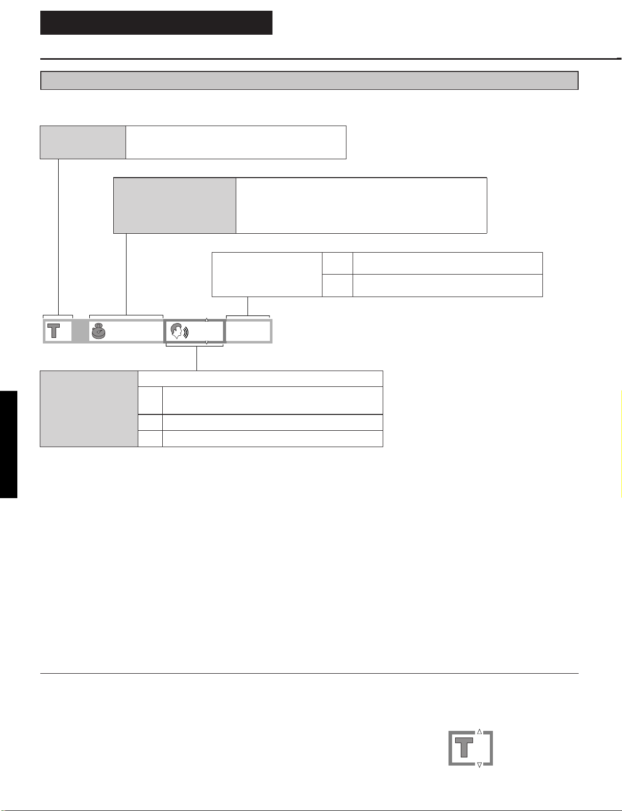
Screen for player information
OPERATING INSTRUCTIONS
A-B repeat play
Repeat play
•DVD
Cinema Dialogue
•Video CD/CD
Play mode
Press SELECT during play to store location A and press SELECT again to store location B and to start
repeat play between the specified two locations. Press SELECT again to return to normal play.
Select the preferred mode during play by
using the cursor buttons (▲, ▼).
OFF
OFF
OFF 0
Select the
preferred mode
during play by
using the cursor
buttons (▲, ▼).
OFF
_
_
_
OFF
ON
PRG
RND
---
Normal play
C
Chapter repeat play
T
Title repeat play
Normal play
T
Track repeat play
A
Disc repeat play
Normal
volume
Louder
volume
Program
play
Random
play
Normal
play
NOFF OFF
DVD
Video CD/
CD
Master
volume
dB
Press SELECT during play
and press SELECT again
at the preferred point to
store a marker. (Marker
no. is displayed instead of
"*".)
•To recall a marker, select
Marker
Adjust the master volume by
using the cursor buttons
(▲, ▼).
0 to – 127 dB or –
the preferred marker no.
by using the cursor
buttons (
the selection using the
cursor button (▲).
•To clear a marker, select
the preferred marker no.
using the cursor buttons
( , ) and press
▲
CLEAR.
▲
▲
▲
, ) and enter
DVD-S795/S705
Select the preferred mode by using the cursor buttons (▲, ▼) and press SELECT.
N Normal mode F Fine mode
S Soft mode C Cinema mode
User selection mode (Adjust the picture quality as you like.)
Cinema
Image
(DVD/Video
CD only)
Notes:
•Repeat play and marker functions do not work with an interactive DVD or during menu play of a Video CD with playback control.
•A-B repeat play does not work with an interactive DVD.
•It is not possible to change the play mode using the On-Screen Menu Icons.
For your reference:
•The master volume can be set and stored separately for DVD, Video CD and CD.
When U is selected and SELECT is pressed, the On-Screen Menu Icon as shown below appears.
U
Contrast (+ 7 to – 7) Equalizer (+ 1/0/– 1) Brightness (0 to 15)
Select the preferred item by using the cursor buttons ( , ) and select the preferred value by using the
cursor buttons (▲, ▼).
0000
Color hue (+ 7 to – 7)
1 - 15
▲
▲
Page 18
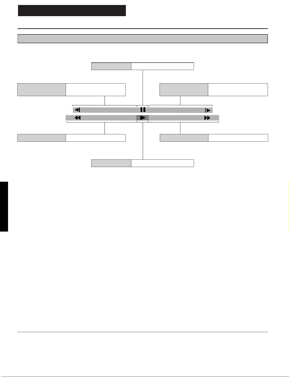
OPERATING INSTRUCTIONS
Detailed descriptions of each On-Screen Menu Icon
Shuttle screen
Still/Pause Press the cursor button (▲).
Slow-motion play
(Backward)
Press the cursor button (
(DVD only)
p
100
Play Press the cursor button (▼).
).
▲
▲
Slow-motion play
(Forward)
Rapid advance Press the cursor button ( ).Rapid reverse Press the cursor button ( ).
Press the cursor button ( ).
(DVD/Video CD only)
µ
100
▲▲
DVD-S795/S705
For your reference:
•Each time the cursor button (
•The figures appearing at both ends of the shuttle screen stand for the maximum speeds of rapid reverse and rapid advance.
(DVD: + 100/– 100, Video CD: + 40/– 40, CD: + 50/– 50)
▲
, ) is pressed, the speed of rapid reverse/advance and slow-motion play increases up to 5 steps.
▲
1 - 16
Page 19
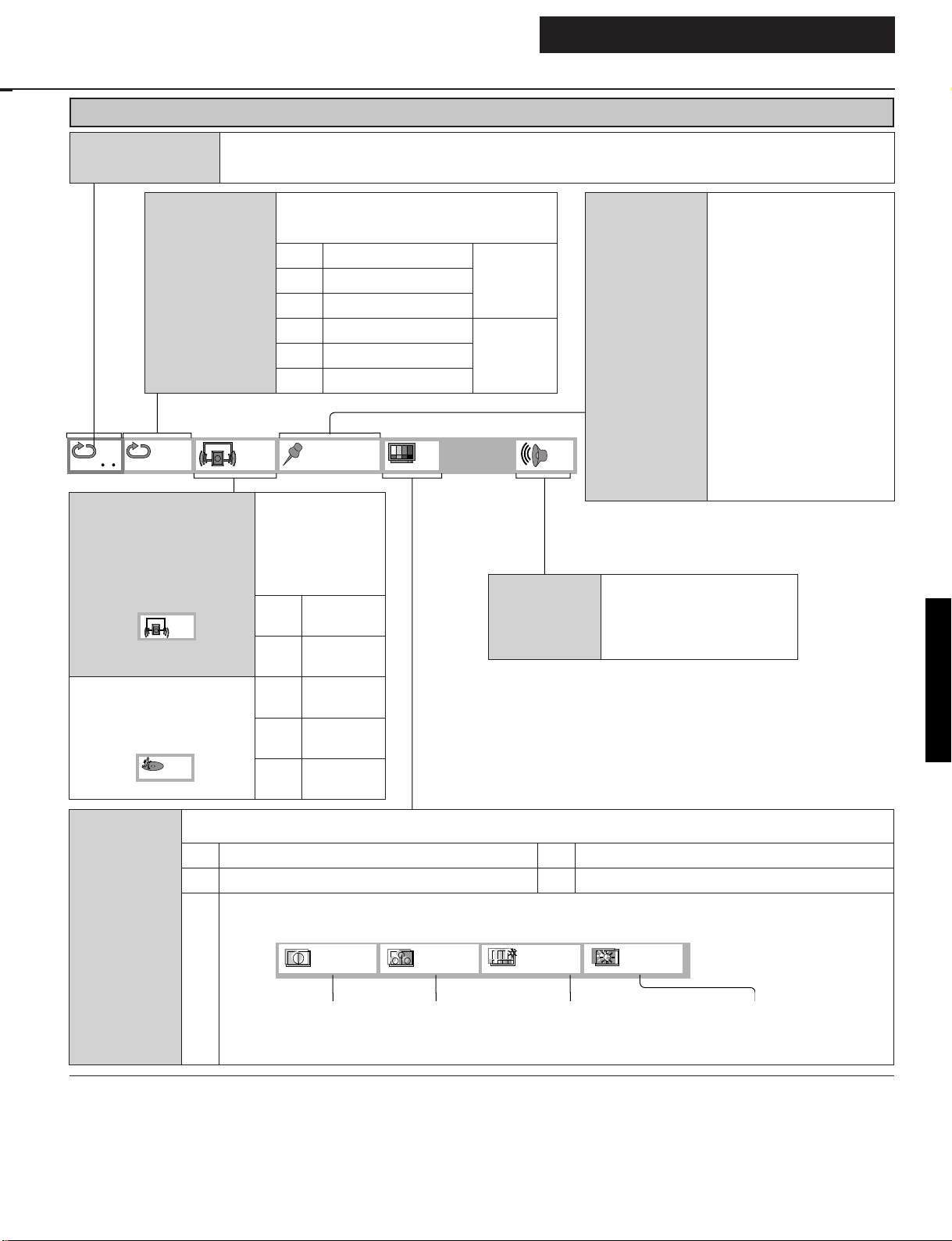
SECTION2
ASSEMBLING AND DISASSEMBLING THE CASING AND CHECKING C.B.A.s
1. Disassembly Procedure
When servicing the unit, use the following procedure to disassemble the casing and inside parts for internal inspection.
Top cover
Tray
Front panel
Rear panel
Mechanism unit
Module C.B.A.
Power SW C.B.A.
Mother C.B.A.
Power Supply
C.B.A.
V. Comp C.B.A.
(U, C MODELS)
Scart C.B.A.
(B, G MODELS)
DVD-S795/S705
2 - 1
Page 20
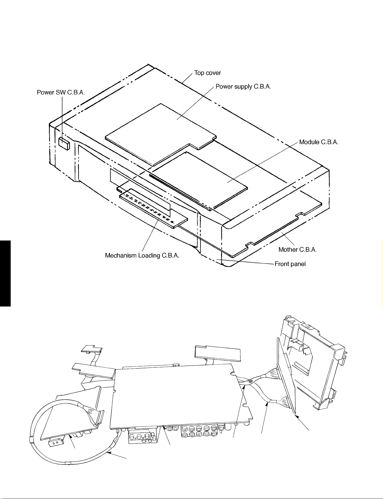
2. Casing Parts and C.B.A. Positions
3. Service Positions
DVD-S795/S705
Note
To inspect the loading base unit, position the left side upward (as viewed from the front).
Power supply C.B.A.
TX946360
Mother C.B.A.
TX946370
TX946370
Module C.B.A.
2 - 2
Page 21
4. Disassembling the Top Cover
1. Remove the 4 screws.
Screw Top cover
Screw
2. Remove the 3 screws.
Screw
5. Disassembling the Tray
1. Turn the level clockwise.
2. Move the tray in the direction of the arrow until it locks.
3. Release the tab locks on the left and right, then pull out the
tray.
Tab
Lever
Tab
6. Disassembling the Front Panel
1. Release the 3 tabs on the bottom.
2. Release the 2 tabs on the left and right.
DVD-S795/S705
NOTE for G: Gold Model only
Before disassembling the top cover, remove the side
panels by the 4 screws.
Side panel
Screw
Screw
3. Release the 2 tabs.
4. Disconnect the 2 flexible cables.
Tab
Flexible
cable
Flexible
cable
2 - 3
Page 22
7. Disassembling the Loading
Base Unit
1. Remove the 4 screws.
2. Pull out the loading base unit vertically.
Note
There is a danger of damaging the connectors.
Loading Base Unit
Screw
Connector
Screw
2. Connect the module C.B.A. to the mother C.B.A. with the
extension cables for inspection.
•Extension cables: TX946370 (JGS0098)
Mother C.B.A. Module C.B.A.
PP4201-PS4201
PP3201-PS3201
Mother C.B.A.
PS4201
PP4201
Note
Be sure to initialize the player whenever you replace a
C.B.A. (Refer to section 1-9, Initializing the DVD Player.)
PP3201
PS3201
8. Checking the Module C.B.A.
1. Remove the 2 screws.
DVD-S795/S705
Module C.B.A.
PS4201
Screw
PS3201
9. Disassembling the Rear Panel
1. Remove all of the screws connected to the rear panel.
(The number of screws varies according to the model).
Screw
Screw
Screw
Screw
2. Release the two tabs on the left and right.
2 - 4
Page 23
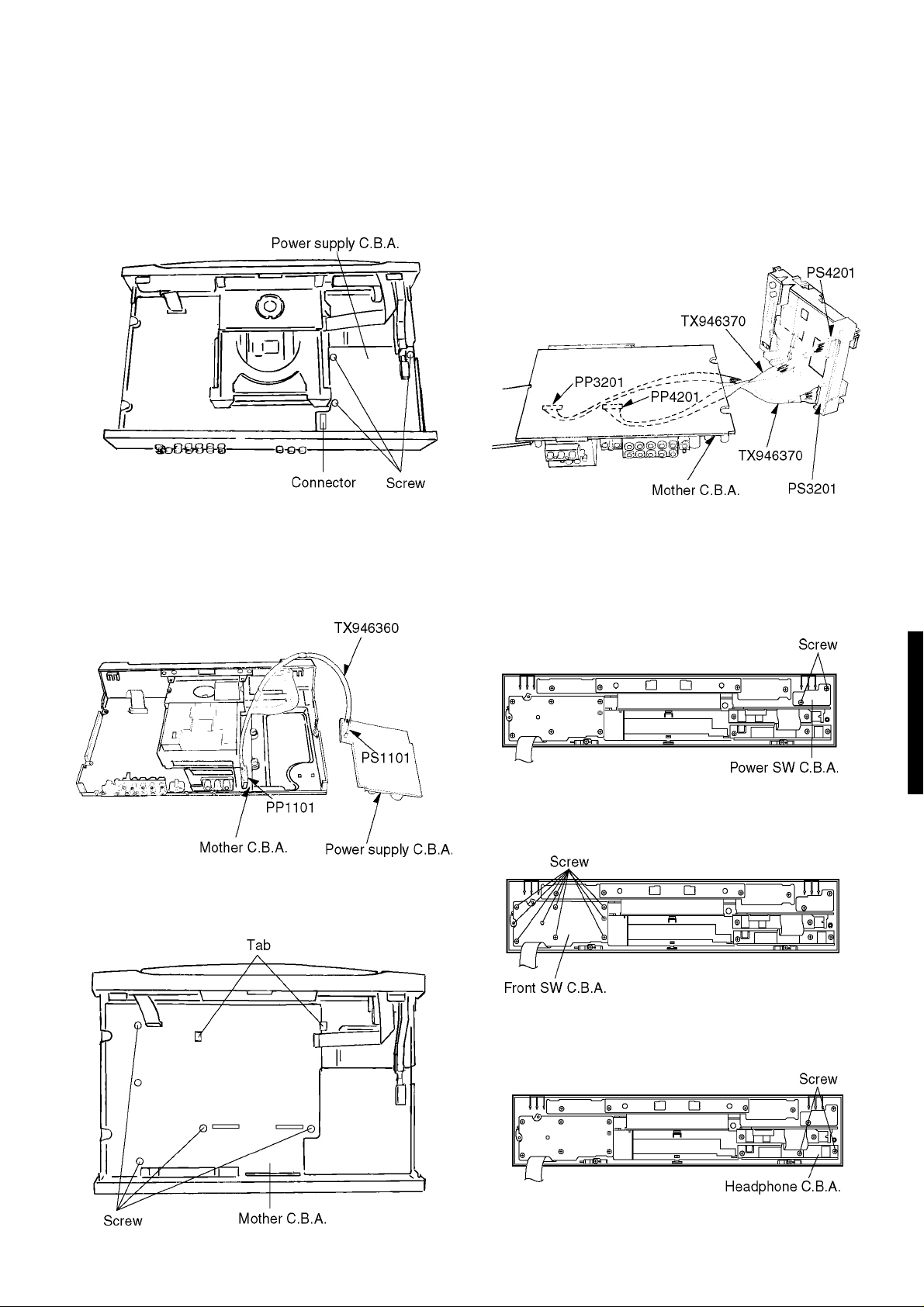
10. Checking the Power Supply
C.B.A.
1. Remove the 3 screws.
2. Carefully pull out the power supply C.B.A.
Note
There is a danger of damaging the connectors.
3. Connect the power supply C.B.A. and the mother C.B.A.
with the extension cable for inspection.
•Extension cable: TX946360(JGS0099)(connects the power
supply C.B.A. PS1101 and the mother C.B.A. PP1101)
3. Checked by connecting the module C.B.A. and the mother
C.B.A. with the extension cables.
Extension cables: TBD (two)
Module C.B.A. Mother C.B.A.
PS3201–PP3201
PS4201–PP4201
Note
Be sure to intialize the player whenever you replace a
C.B.A. (Refer to section 1-9, Initializing the DVD player.)
12. Checking the Power Switch C.B.A.
1. Remove the 2 screws.
DVD-S795/S705
11. Checking the Mother C.B.A.
1. Remove the 5 screws.
2. Release the 2 tabs.
13. Checking the Front Switch C.B.A.
1. Remove the 9 screws.
14. Checking the Headphone C.B.A.
1. Remove the 2 screws.
2 - 5
Page 24
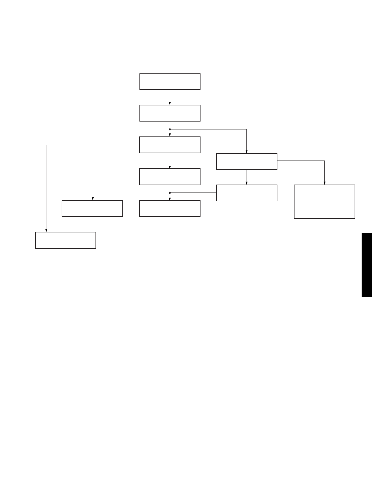
ASSEMBLING AND DISASSEMBLING THE OPTICAL PICKUP (MECHANICAL P ARTS)
The optical pickup can be damaged by static electricity from your body. Be sure to take static electricity countermeasures when
working around the optical pickup.
1. Handling the Optical Pickup
The optical pickup can be damaged by static electricity from your body. Be sure to take static electricity countermeasures when
working around the optical pickup.
1. The optical pickup is an extremely high-precision mechanism. Do not subject it to strong impact.
2. To preserve the quality of the optical pickup replacement parts during transport and installation, the terminals of the laser
diode are short-circuited. After replacing the parts, use the proper procedure to return the laser diode to its original condition.
(Refer to page 2-11, Assembling the Optical Pickup.)
3. Testers cannot be used to check the laser diode of the optical pickup. The power supply inside the tester can easily damage
the laser diode.
4. Take care when handling the flexible cable because excessive force can cause it to break.
5. You cannot adjust the semifixed resistor for laser power adjustment. Do not turn it.
2. Disassembly Procedure
Use the following procedure to replace major parts.
For the assembly procedure, follow the flow chart in reverse.
Top cover
Tr ay
DVD-S795/S705
Pulley gear
Front panel
Mechanism unit
Clamp base unit
Static electricity
countermeasures
Traverse unitMechanism Loading C.B.A.
Intermediate chassis
Vertical cam, Drive gear
Clamper weight
Clamper yoke
Magnet
Clamper
Deceleration gear
2 - 6
Page 25
3. Lubricating the Loading Base Unit
When replacing parts, Iubricate the parts maked “XXX” in the diagram
Clamper weight
Clamper yoke
Clamp base unit
Tray
Magnet
Clamper
Traverse unit
Grease EM-30LG
(TX946270)
0.01g
Intermediate
chassis
Grease EM-30LG
(TX946270)
0.01g
Grease EM-30LG
(TX946270)
0.01g
Grease EM-30LG
(TX946270)
0.01g
Belt
Pulley gear
Deceleration
gear
Grease EM-30LG
(TX946270)
0.01g
Drive gear
Vertical cam
drive gear
Grease EM-30LG
(TX946270)
0.01g
DVD-S795/S705
Grease EM-30LG
(TX946270)
0.02g
Grease EM-30LG
(TX946270)
0.02g
2 - 7
Mechanism Loading C.B.A.
Page 26
4. Static Electricity Countermeasures
The laser diode inside the traverse unit (optical pickup) can be damaged by static electricity from your body. Be sure to take static
electricity countermeasures when working around the optical pickup.
4-1. Static Electricity Countermeasure Methods
1. Ground yourself
Use an anti-static wrist strap to discharge static electricity from your body.
2. Ground the workbench
Lay a conductive meterial (sheet) or steel sheet on the surface where the traverse unit (optical pickup) is to be placed, then
ground the sheet.
Anti-static wrist strip
1M
Conductive material
(sheet) or steel sheet
4-2. Short-circuit the laser diode
Solder the land in the flexible cable of the optical pickup.
Notes
• Be sure to do this befer disconnecting the flexible cable of the optical pickup from the module C.B.A.
• Use an anti-static soldering iron to short-circuit and unshort-circuit laser diode.
(Recommended soldering iron: Hakko with ESD countermeasure)
• After you have finished repairing the laser diode, follow the correct procedure to remove the solder from the short-circuit
DVD-S795/S705
location. (Refer to page 2-7, Assembling and Disassembling the Optical Pickup (Mechanical Parts).)
Pickup unit
Flexible cable
Solder
(Magnified view)
2 - 8
Use a clip or other item to
ground the unit.
Page 27
Screw
Intermediate chassis
Traverse unit
5.
Disassembling the Clamp Base Unit
1. Remove the 2 screws.
2. Release the 3 tabs on the clamper.
Loading base
Screw
Screw
Clamp base unit
6. Disassembling the Clamper
Weight, Clamper Yoke, Magnet
and Clamper
1. Remove the tab, and pull out the clamper.
Tab
Clamper unit
Yoke
Magnet
Screw
Clamper weight
Clamper yoke
Magnet
3-clamper tabs
Clamper
Clamper base
7. Disassembling the Traverse
Unit
1. Remove the 3 screws.
DVD-S795/S705
Clamper base
Stopper
Tab
Note
Be sure to take static electricity counterneasures before
disconnecting the flexible cable. (Refer to page 2-8,
Static Electricity Countermeasures.)
2 - 9
Page 28

2. Disconnect the 2 flexible cables.
Hook
FPC holder
Optical pickup unit
Tilt spring
Spring holder 1
Screw
Guide shaft
Tab
Traverse chassis
FPC holder
8. Disassembling the Stepping
Motor Unit
1. Disconnect the flexible cable.
2. Remove the 2 screw.
Note
Take care when handling the flexible cable bacause it can be
broken by excessive force.
9. Disassembling the Optical
Pickup Unit
1. Remove the hook of the FPC holder, then remove the FPC
holder itself.
2. Remove the screw.
3. Release the tab, then remove spring holder 1.
Note
Be sure not to lose the spring.
4. Remove the guide shaft.
Note
Be sure to adjust the optical pickup titl after replacing the
optical pickup.
(Refer to page 2-13, Optical Pickup Tilt Adjustment.)
DVD-S795/S705
Stepping motor
Screw
Stepping motor unit
Flexible cable
Connector
C.B.A
Motor FPC
Traverse chassis
2 - 10
Page 29

10. Disassembling the Nut Unit
1. Remove the screw.
Notes
•The nut unit is not part of the optical pickup.
Before replacing the optical pickup, remove the nut
unit for use with the new optical pickup.
•After installation, use screw lock to lock the screw in
position.
•When reassembling, use screw lock to lock the screw
in position after attaching it.
12. Assembling the Optical Pickup
1. Install the optical pickup.
Note
Take care not of attach the tilt spring and guide shaft in
the wrong order.
Protruding part
Tilt spring
Spring holder 1
Guide shaft
Nut unit
screw
Nut spring
Nut
(Rear surface)
Optical pickup
11. Disassembling the Sub-Shaft
Preload Spring
1. Remove the screw.
Notes
•Handle the sub-shaft preload spring carefully because
the shape of the tip is easily deformed.
•The sub-shaft preload spring is not part of the optical
pickup. Before replacing the optical pickup, remove
the sub-shaft preload spring for use with the new
optical pickup.
•After installation, use screw lock to lock the screw in
position.
Screw
Sub-shaft preload spring
Traverse chassis
Adjustment screw
Guide shaft
Tab
Traverse chassis
2. Fit the protruding part of the pickup FPC into the convexpart
of the FPC holder to install it.
Hook
FPC holder
Screw
Spring holder 1
Tilt spring
Optical pickup unit
FPC holder
Protruding part
Pickup FPC
Pickup FPC
Opening
DVD-S795/S705
(Rear surface)
Optical pickup
Traverse chassis
2 - 11
Page 30

3. Insert the pickup FPC into connector FP5201 on the module
C.B.A.
4. Remove the solder from the pickup FPC’s soldered short-circuit
Remove the solder.
13. Disassembling the Spring
Motor Unit
1. Remove the three screw.
Note
Be sure to adjust the optical pickup tilt after replacing
the spindle motor unit.
Spindle motor unit
Traverse chassis
Open the circuit after short-circuiting it.
DVD-S795/S705
5. Adjust the optical pickup tilt after removing the solder.
(Refer to page 2-13, Optical Pickup Tilt Adjustment.)
(Magnified view)
Solder removal
direction
Screw
2 - 12
Page 31

14. Optical Pickup Tilt Adjustment
Measurement point
Main unit
service display
Measuring equipment, tools Adjustment value
Hex wrench (part number: TX946380)
Screw lock (part number: TX946400)
• Replaced the optical pickup.
STEP7
STEP1
"STOP/PAUSE" button: main unit
"OPEN/CLOSE" button: main unit
"5" button: remote control unit
STEP2
Main unit display
Check to see that "JIT xxx" is displayed.
STEP3
Play test disc title 1
(inner periphery)
Tangential adjustment screw
Adjust to the minimum jitter value.
STEP4
Play test disc title 43
(outer periphery)
Tilt adjustment screw 1
Adjust to the minimum jitter value.
• Replaced the spindle motor.
• Replaced the peripheral parts
Tangential adjustment screw
Tilt adjustment screw
of the optical pickup, etc.
Present jitter value.
Adjustment point Mode Disc
DVDT-S15 (AAX07320)
or
DVDT-S01 (TX946080)
Tangential adjustment screw
Tilt adjustment screw 1
Tilt adjustment screw 2
Press
simultaneously
Do steps 3-5
from the bottom
of the main unit
using a hex wrench.
T1 (inner periphery) play
T2 (outer periphery) play
Adjust to the minimum jitter value.
Change in
jitter value
AB
DVD-S795/S705
STEP5
Play test disc title 43
(outer periphery)
Tilt adjustment screw 2
Adjust to the minimum jitter value.
STEP6
NG
Check condition
after adjustment
OK
STEP7
Repeat adjustment tilt
adjustment screws
1 and 2 alternately,
two or three times.
Play the disc to make sure
there is no picture
degradration in the inner,
middle and outer
peripheries, and no audio
skipping.
Optimum
point
Adjustment angle
• Jittervaluedependsonthemodel:
(1)IfthejittervaluechangeslikeA,
theoptimumpointiseasytofind
(2)IfthejittervaluechangeslikeA,
settheoptimumpointnearthemiddle.
2 - 13
Page 32

STEP6
STEP7
Pull out the traverse unit.
(Refer to disassembly procedure
in this manual.)
STEP8
Lock the adjustment screw in
position using screw lock
(part number: TX946400).
STEP9
Assemble the main unit.
STEP10
Follow procedure
for handling
after repairs
are completed.
End
With the power supply turned on:
1. Use the OPEN/CLOSE
2. Use the POWER button
3. Disconnect the power plug
Remove in the order
of top cover, tray
and clamper base.
button to close the tray.
to turn off the power.
from the outlet.
Screw lock
(0.02 g)
Screw lock
(0.02 g)
Adjustment screws
Screw lock
(0.02 g)
Traverse unit
(rear side)
Notes
•Adjustment is generally unnecessary after replacing other parts of the traverse unit. However, adjust if there is a noticeable
DVD-S795/S705
degradation in picture quality.
•Optical adjustments cannot be made inside the optical pickup.
•Adjustment is generally unnecessary after replacing the traverse unit.
2 - 14
Page 33

15. Disassembling the
Screw
Screw
Intermediate Chassis
1. Push the stopper downward, then rotate it until it contacts
the vertical cam.
2. Release the 2 tabs.
Stopper
Loading base
Vertical cam
Intermediate
chassis
17. Disassembling the Pulley Gear
and Deceleration Gear
1. Remove the screw.
2. Remove the pulley gear.
3. Remove the belt.
4. Remove the deceleration gear.
Drive gear
Deceleration gear
Pulley gear
Tabs
Contact
position
16. Disassembling the Vertical
cam and Drive gear
1. Rotate the vertical cam until it reaches the contact position.
2. Lift the vertical cam straight upward to pull it out.
2. Remove the Drive gear.
Loading base
Vertical cam
Belt Screw
Deceleration gear
Belt
Pulley gear
Drive gear
18. Disassembling the Mechanism
Loading C.B.A.
1. Remove the 2 screw.
DVD-S795/S705
Assembly guide
Double switch
Drive gear Contact position
2. Remove the 2 screw.
3. Release the three tabs.
(Rear surface)
Tab
2 - 15
Tab
Tab
Mechanism Loading C.B.A.Screw
Page 34

19. Lubricating the Optical Pickup and Peripheral Parts
When replacing parts, lubricate the parts marked “xxx” in the diagram.
Froil 946P
(part number. TX946410)
0.01g
Spindle motor unit
Screwlock
Three-Bond1401C
MC grease PD No. 10
(part number. TX946390)
0.04g
(gearshaft opening)
(0.02g)
(part number. TX946400)
MC grease PD No. 10
(part number. TX946390)
Screwlock
Three-Bond1401C
(0.02g)
(part number. TX946400)
0.04g
DVD-S795/S705
Stepping motor unit
Screwlock
Three-Bond1401C
(0.02g)(part number. TX946400)
2 - 16
Page 35

ELECTRICAL ADJUSTMENT
1. Video Output (Luminance Signal) Adjustment
Do this adjustment after replacing a C.B.A.
Measurement point Adjustment point Mode Disc
Color bar 75%
Video output terminal VR3501(mother C.B.A.)
Measuring equipment, tools
Screwdriver, Oscilloscope
200mV/div, 10 sc/div
Purpose: To maintain video signal output compatibility.
1. Connect the oscilloscope to the video output terminal and terminate at 75 ohms.
2. Adjust VR3501 so that the luminance signal (Y+S) level becomes 1000 mVp-p–20 mV.
PLAY (Title 46): DVDT-S15
PLAY (Title 10): DVDT-S01
Adjustment value
1000mVp-p±13mV
DVDT-S15 (AX07320)
or
DVDT-S01 (TX946080)
VR3501
2. Video Output (Chrominance Signal) Adjustment
Do this adjustment after replacing a C.B.A.
Measurement point Adjustment point Mode Disc
Color bar 75%
Video output terminal VR3511(mother C.B.A.)
Measuring equipment, tools
Screwdriver, Oscilloscope
200mV/div, 10 sc/div
Purpose: To maintain video signal output compatibility.
1. Connect the oscilloscope to the video output terminal and terminate at 75 ohms.
2. Adjust VR3511 so that the chrominance signal (C) level becomes 675 mVp-p–13 mV.
PLAY (Title 46): DVDT-S15
PLAY (Title 10): DVDT-S01
Adjustment value
675mVp-p±13mV
Screw driver
DVD-S795/S705
DVDT-S15 (AX07320)
or
DVDT-S01 (TX946080)
2 - 17
Screw driver
VR3511
Page 36

3. Video Component Signal (CB) Output Adjustment
Do this adjustment after replacing a C.B.A.
Measurement point Adjustment point Mode Disc
Video output terminal
(Y) (CB) Output terminal
Measuring equipment, tools
Screwdriver, Oscilloscope
100mV/div, 10 sc/div
Purpose: To maintain video signal output compatibility.
1. Connect the oscilloscope to the video output terminal and terminate at 75 ohms.
2. Apply the trigger at the Y output terminal signal.
3.
Adjust VR3201 so that the video component signal (CB) level becomes 525 mVp-p–1 1 mV. (B, A, G Models)/486mVp-p–10mV(U, C Models)
VR3201(mother C.B.A.)
Color bar 75%
PLAY (Title 46): DVDT-S15
PLAY (Title 10): DVDT-S01
Adjustment value
525mVp-p±11mV (B, A, G Models)
486mVp-p–10mV (U, C Models)
For B, A, G Models
DVDT-S15 (AX07320)
or
DVDT-S01 (TX946080)
Screw
driver
VR3201
For U, C Models
DVD-S795/S705
486mV
–
10mV
2 - 18
Page 37

SECTION3
ABBREVIATIONS
INITIAL/LOGO ABBREVIATIONS
A A0~UP ADDRESS
ACLK AUDIO CLOCK
AD0–UP ADDRESS BUS
ADATA AUDIO PES PACKET DATA
ALE ADDRESS LATCH ENABLE
AMUTE AUDIO MUTE
AREQ AUDIO PES PACKET REQUEST
ARE AUDIO RF
ASI SERVO AMP INVERTED INPUT
ASO SERVO AMP OUTPUT
ASYNC AUDIO WORD DISTINCTION SYNC
B BCK BIT CLOCK (PCM)
BCKIN BIT CLOCK INPUT
BDO BLACK DROP OUT
BLKCK SUB CODE BLOCK CLOCK
BOTTOM CAP. FOR BOTTOM HOLD
BYP BYPATH
BYTCK BYTE CLOCK
C CAV CONSTANT AUGULAS VELOCITY
CBDO CAP. BLACK DROP OUT
CD COMPACT DISC
CDSCK CD SERIAL DATA CLOCK
CDSRDATA CD SERIAL DATA
CDRF CD RF (EFM) SIGNAL
CDV COMPACT DISC-VIDEO
CHNDATA CHANNEL DATA
CKSL SYSTEM CLOCK SELECT
CLV CONSTANT LINEAR VELOCITY
COFTR CAP. OFF TRACK
CP A CPU ADDRESS
CPCS CPU CHIP SELECT
CPDT CPU DATA
CPUADR CPU ADDRESS LATCH
CPUADT CPU ADDRESS DATA BUS
CPUIRQ CPU INTERRUPT REQUEST
CPRD CPU READ ENBLE
CPWR CPU WRITE ENABLE
CS CHIP SELECT
CSYNCIN COMPOSITE SYNC IN
CSYNCOUT COMPOSITE SYNC OUT
D DACCK D/A CONVERTER CLOCK
DEEMP DEEMPHASIS BIT ON/OFF
DEMPH DEEMPHASIS SWITCHING
DIG0~UP FL DIGIT OUTPUT
DIN DATA INPUT
DMSRCK DM SERIAL DATA READ CLOCK
DMUTE DIGITAL MUTE CONTROL
DO DROP OUT
DOUT0–UP DATA OUTPUT
DRF DATA SLICE RF (BIAS)
DRPOUT DROP OUT SIGNAL
DREQ DATA REQUEST
DRESP DATA RESPONSE
DSC DIGITAL SERVO CONTROLLER
DSLF DATA SLICE LOOP FILTER
DVD DIGITAL VIDEO DISC
INITIAL/LOGO ABBREVIATIONS
E EC ERROR TORQUE CONTROL
ECR ERROR T ORQUE CONTROL
REFERENCE
ENCSEL ENCODER SELECT
ETMCLK EXTERNAL M CLOCK (81MHz/40.5MHz)
ETSCLK ETSCLK EXTERNAL S CLOCK (54MHz)
F FBALFCLK FOCUS BALANCEFRAME CLOCK
FE FOCUS ERROR
FFI FOCUS ERROR AMP INVERTED INPUT
FEO FOCUS ERROR AMP OUTPUT
FG FREQUENCY GENERATOR
FSC FREQUENCY SUB CARRIER
FSCK FS (384 OVER SAMPLING) CLOCK
G GND COMMON GROUNDING (EARTH)
H HA0–UP HOST ADDRESS
HD0–UP HOST DATA
HINT HOST INTERRUPT
HRXW HOST READ/WRITE
I IECOUT IEC958 FORMAT DATA OUTPUT
IPFRAG INTERPORATION FLAG
IREF I (CURRENT) RETERENCE
ISEL INTERFACE MODE SELECT
L LDONL LASER DIODE CONTROL
LPC LASER POWER CONTROL
LRCK L CH/R CH DISTINCTION CLOCK
M MA0–UP MEMORY ADDRESS
MCK MEMORY CLOCK
MCKI MEMORY CLOCK INPUT
MCLK MEMORY SERIAL COMMAND CLOCK
MDQ0–UP MEMORY SERIAL COMMAND DATA
MDQM MEMORY DATA INPUT/OUTPUT
MLD MEMORY DATA I/O MASK
MPEG MEMORY SERIAL COMMAND LOAD
MOTION PICTURE IMAGE CODING
EXPERT GROUP
O ODC OPTICAL DISC CONTROLLER
OFTR OFF TRACKING
OSCI OSCILLATOR INPUT
OSCO OSCILLATOR OUTPUT
OSD ON SCREEN DISPLAY
P P1~UP PORT
PCD CD TRACKING PHASE DIFFERENCE
PCK PLL CLOCK
PDVD DVD TRACKING PHASE DIFFERENCE
PEAK CAP. FOR PEAK HOLD
PLLCLKPLLO CHANNEL PLL CLOCK
K PLL LOCK
PWMCTL PWM OUTPUT CONTROL
PWMDA PULSE WAVE MOTOR DRIVE A
PWMOA, B PULSE WAVE MOTOR OUT A, B
DVD-S795/S705
3 - 1
Page 38

INITIAL/LOGO ABBREVIATIONS
R RE READ ENABLE
RFENV RF ENVELOPE
RFO RF PHASE DIFFERENCE OUTPUT
RS (CD-ROM) REGISTER SELECT
RSEL PF POLARITY SELECT
RST RESET
RSV RESERVE
S SBI0, 1 SERIAL DATA INPUT
SBO0 SERIAL DATA OUTPUT
SBT0, 1 SERIAL CLOCK
SCK SERIAL DATA CLOCK
SCKR AUDIO SERIAL CLOCK RECEIVER
SCL SERIAL CLOCK
SCLK SERIAL CLOCK
SDA SERIAL DATA
SEG0–UP FL SEGMENT OUTPUT
SELCLK SELECT CLOCK
SEN SERIAL PORT ENABLE
SIN1, 2 SERIAL DATA IN
SOUT1, 2 SERIAL DATA OUT
SPDI SERIAL PORT DATA INPUT
SPDO SERIAL PORT DATA OUTPUT
SPEN SERIAL PORT R/W ENABLE
SPRCLK SERIAL PORT READ CLOCK
SPWCLK SERIAL PORT WRITE CLOCK
SQCK SUB CODE Q CLOCK
SQCX SUB CODE Q DATA READ CLOCK
SRDATA SERIAL DATA
SRMADR SRAM ADDRESS BUS
SRMDT0–7 SRAM DATA BUS 0–7
SS ST ART/STOP
STAT STATUS
STCLK STREAM DATA CLOCK
STD0–UP STREAM DATA
STENABLE STREAM DATA INPUT ENABLE
STSEL STREAM DATA POLARITY SELECT
STVALID STREAM DATA VALIDITY
SUBC SUB CODE SERIAL
SBCK SUB CODE CLOCK
SUBQ SUB CODE Q DATA
SYSCLK SYSTEM CLOCK
T TE TRACKING ERROR
DVD-S795/S705
TIBAL BALANCE CONTROL
TID BALANCE OUTPUT 1
TIN BALANCE INPUT
TIP BALANCE INPUT
TIS BALANCE OUTPUT 2
TPSN OP AMP INPUT
TPSO OP AMP OUTPUT
TPSP OP AMP INVERTED INPUT
TRCRS TRACK CROSS SIGNAL
TRON TRACKING ON
TRSON TRAVERSE SERVO ON
INITIAL/LOGO ABBREVIATIONS
V VBLANK V BLANKING
VCC COLLECTOR POWER SUPPLY
VOLTAGE
VCDCONT VIDEO CD CONTROL (TRACKING
BALANCE)
VDD DRAIN POWER SUPPLY VOLTAGE
VFB VIDEO FEED BACK
VREF VOLTAGE REFERENCE
VSS SOURCE POWER SUPPLY VOLTAGE
W WAIT BUS CYCLE WAIT
WDCK WORD CLOCK
WEH WRITE ENABLE HIGH
WSR WORD SELECT RECEIVER
X X X' TAL
XALE X ADDRESS LA TCH ENABLE
XAREQ X AUDIO DATA REQUEST
XCDROM X CD ROM CHIP SELECT
XCS X CHIP SELECT
XCSYNC X COMPOSITE SYNC
XDS X DATA STROBE
XHSYNCO X HORIZONTAL SYNC OUTPUT
XHINT XH INTERRUPT REQUEST
XI X' TAL OSCILLATOR INPUT
XINT X INTERRUPT
XMW X MEMORY WRITE ENABLE
XO X' TAL OSCILLATOR OUTPUT
XRE X READ ENABLE
XSRMCE X SRAM CHIP ENABLE
XSRMOE X SRAM OUTPUT ENABLE
XSRMWE X SRAM WRITE ENABLE
XVCS X V-DEC CHIP SELECT
XVDS X V-DEC CONTROL BUS STROBE
XVSYNCO X VERTICAL SYNC OUTPUT
3 - 2
Page 39

BLOCK DIAGRAM
1. OVERALL BLOCK DIAGRAM
3 - 3 3 - 4
Page 40

2. SERVO BLOCK DIAGRAM
3 - 5
3 - 6
Page 41

3. VIDEO BLOCK DIAGRAM
3 - 7
3 - 8
Page 42

4. AUDIO BLOCK DIAGRAM
3 - 9
3 - 10
Page 43

SCHEMATIC DIAGRAM
1. POWER SUPPLY SCHEMATIC DIAGRAM (FOR U, C MODELS)
U, C MODELS
5.1
0
5.1
0
3.4
0
3.35.1
3.4
0
12.5
17.0
—26.0
0
0.2
0.5
0
16.6
0
0.5
5.2
4.1
3.9
2.5
3.4
8.9
8.9
0
3 - 11
0
3 - 12
Page 44

2. POWER SUPPLY SCHEMATIC DIAGRAM (FOR B, G, A)MODELS
B, G, A MODELS
0
5.1
5.1
0
3.4
0
5.1
3.4
12.5
17.0
—26.0
0
0.2
0.5
0
16.6
0
0.5
5.2
4.1
3.9
2.5
3.4
3.3
0
8.9
8.9
0
3 - 13
0
3 - 14
Page 45

3. ADSC (MODULE C.B.A. 1/8) SCHEMATIC DIAGRAM
IC2001
STOP 3.1 0 0 0 3.1 0 3.1
PLAY 3.1 0 0 0 3.1 0 3.1
STOP
PLAY
STOP
PLAY
STOP
PLAY
STOP
PLAY
STOP
PLAY
STOP
PLAY
STOP
PLAY
STOP
PLAY
STOP
PLAY
STOP
PLAY
STOP
PLAY
STOP
PLAY
STOP
PLAY
STOP
PLAY
STOP
PLAY
STOP
PLAY
STOP
PLAY
STOP
PLAY
1234567
8 9 10 11 12 13 14
3.1 0 3.1 3.1 0 0.1 0.1
3.1 0 3.1 3.1 0 3.1 0
15 16 17 18 19 20
0 3.1 0 0.1 0.1 0.1
3.1 0 0 3.1 1.5 1.8
22 23 24 25 26 27
0.1 1.6 1.6 1.6 1.6 0
1.8 1.5 1.5 1.5 1.5 0
29 30 31 32 33 34
0 1.6 0.1 0.9 0 3.1
0 1.6 0 0 3.1 3.1
36 37 38 39 40
00000
00000
43 44 45 46 47
0 0.2 0 0 0
0 0.2 0 0 0
50 51 52 53 54
0 0 3.1 0 0
0 0 3.1 0 0
57 58 59 60
0001.5
3.1 0 0 0
64 65 66 67
0.2 0 0 0
1.5 0 0 0
71 72 73 74
1.5 0 0 3.1
1.4 0.1 0 3.1
78 79 80
000
2.1 3.1 0.1
85 86 87
1.4 0 1.4
0.1 1.4 1.3
92 93 94
1.4 1.4 1.4
1.4 1.4 1.2
99 100
0.1 1.6
1.9 1.6
106 107 108 109 110 111 112
3.1 0.1 0.1 0.1 1.5 0.1 0
3.1 0.2 1.4 0.2 0.2 1.4 0
113 114 115 116 117 118 119
0 3.1 0.1 0 0.1 1.4 0
0 3.1 2.3 0 1.2 1.4 0
121 122 123 124 125 126
120
0.1 0 0.1 0.4 0.1 0.1
1.6
1.6 0 0 0.6 0 0
1.5
127 128
0 3.1
00
81 82 83 84
1.3 0 0 0
1.1 1.4 0.1 0.1
88 89 90 91
0 1.4 0.6 1.4
2.1 1.4 0.6 1.4
95 96 97 98
0 0 3.1 0.1
1.2 0 3.1 1.5
101 102 103 104 105
0.1 1.4 1.4 1.4 1.4
1.4 1.3 1.4 1.6 0.3
41 42
1.6 0
1.6 1.5
48 49
00
00
55 56
00
1.5 0
61 62 63
0.2 1.5 0.2
0 0.1 1.5
68 69 70
0 3.1 3.1
0 3.1 3.1
75 76 77
0 0 1.4
0.1 0.5 0.1
21
1.6
1.5
28
3.1
3.1
35
0
3.0
3 - 15
3 - 16
Page 46

4. SERVO (MODULE C.B.A. 2/8) SCHEMATIC DIAGRAM
0.1(1.5)
0.1(1.4)
1.4(0.8)
0.1(1.3)
1.4(0.7)
2.4(3.1)
1.4
4.9
0
0
0.4(2.7)
1.4(1.5)
0.1(1.3)
0.1(2.5)
0.1(0.5)
8.9(8.8)
0
0
1.4(1.2)
1.4
1.4
1.4
1.4
1.4(1.2)
2.4(3.1)
8.9(8.8)
2.3(1.2)
5.8(3.2)
2.2(5.1)
5.8(3.2)
3.1(0)
0.2(3.1)
0
0(3.5)
0
0.2(3.1)
0(1.5)
2.1
0
2.2(2.9)
5.0(2.9)
5.0(0.3)
5.0(2.9)
5.0(2.9)
5.0(2.9)
0
5.0(0.8)
0(3.5)
2.1
2.1
0
5.0(4.9)
0
0
2.2(0.3)
(7.2)
2.3(0)
2.2(7.2)
2.2(0)
2.2(7.2)
8.9(8.8)
0
8.9(8.8)
0(0.3)
0(0.3)
0.1(0)
0.6
2.2(0)
0
0 3.1
0.2(3.1)
0
3 - 17
3 - 18
Page 47

5. AV DECODER (MODULE C.B.A. 3/8) SCHEMATIC DIAGRAM
3.1
0
2.2(0.3)
2.8(2.5)
2.2(2.4)
2.5
0
0
2.2(2.4)
2.5(2.3)
3.1
2.2(2.5)
2.6(2.2)
3.1
2.1(2.3)
2.7(2.5)
0
2.3(2.2)
2.6(2.4)
0
2.5(2.4)
0.1(2.5)
2.5(2.4)
2.2(2.5)
0
1.5
2.7(2.4)
3.1
3.1
2.2(0)
2.2(0.1)
2.1(0.2)
2.1(0.2)
2.1(0.2)
2.1(0.2)
0.2(3.1)
0.2(0.3)
0
0(0.3)
0(0.3)
0
1.5(0.3)
4.9
0
1.3
4.9
0
3.1
3.1
3.3
0.1(3.0)
0.1(2.9)
0.2(2.8)
2.7(0.3)
IC3001
14710131619
STOP 0 3.1 0 3.1 0 3.1 0
PLAY 0 3.1 0 3.1 0 3.1 0
35 36 37 38 39 40
34
STOP
STOP
STOP
STOP
STOP
STOP 0 5.0 3.1 0 2.4 3.1 3.1 3.1 3.1 3.1 2.4 2.9 2.4 3.1 1.5 0
STOP 2.4 2.4 2.7 2.7 2.8 3.1 2.7 2.8 2.8 2.9 2.9 2.7 2.7 2.8
STOP 1.1 0.6 0.6 0.6 1.6 0.7 0.3 1.2 3.1 1.5 0
STOP 1.5 3.1 0 0 0 1.4 1.5 0 0
STOP 3.2 3.3 1.7 1.7 2.2 0.4 0
STOP
2.6 2.6 0.1 0.1 0.1 3.1
3.1
PLAY
2.0 0 0 1.8 0 3.1
3.1
51
52 53 54 55 56 57 58 59 60
2.7
3.1 0 3.1 3.1 2.7 3.1 3.1 3.0 0
2.0
PLAY
3.1 0 3.0 1.4 2.0 3.1 2.9 3.0 0
68 69 70
0 3.1 0
PLAY
0 3.1 1.4
85 86 87 88 89 90 91 92 93 94 95 96 97 98 99 100
03.100.101.21.53.14.73.101.50000
PLAY
03.11.70.101.61.53.14.73.101.50000
102 103 104
0 0.1 3.1
PLAY
0 0 3.1
120
5.0
PLAY 0.2 0.2 0.2 0 3.1 3.1 3.1 0.3 3.1 2.4 3.1 2.7 3.1 3.1 1.5 0
2.6
138 139 140
2.4 2.3 2.3
PLAY 1.8 1.9 2.4 2.3 2.5 3.1 2.4 2.6 2.5 2.6 2.6 0.1 2.4 2.5
0.2 0.2 0.2
155 156 157 158 159 160
2.3 0 2.8 2.8 2.8 2.8
PLAY 0.7 0.7 0.6 0.5 1.1 0.8 0.8 1.6 3.1 1.5 0
2.5 0 2.5 2.5 2.6 2.6
172 173 174 176 177 178 179 180
3.1 2.9 1.6 2.3 2.3 3.1 1.6 0
PLAY 1.5 3.1 0 0 1.1 1.4 1.5 0 0
3.0 2.9 1.5 0.4 1.4 3.1 1.5 0
190 191 192 193 194 195 197 198 199 200
0.1 3.2 3.3 1.6 0.3 2.6 3.3 1.7 1.8 2.7
PLAY
0 3.1 3.3 1.6 1.8 2.6 3.3 1.9 1.8 2.6
208
0
PLAY
0
71 72 73 74 75 76 77 78 79 80
3.1003.11.400003.1
3.1 0 1.4 3.1 0 1.5 0 0 0 3.1
105 106 107 108 109 110 112 113 114 115 116 117 118 119
0 2.4 2.4 0 5.0 2.4 2.3 3.1 3.1 2.4 0 5.0 0 0
0 0 0.3 0 4.9 0.1 2.2 0.3 3.1 0.2 0.2 2.6 2.6 2.6
121 122 123 124 125 126 127 128 129 130 132 133 134 135 136 137
141 142 143 144 145 146 147 148 149 150 151 152 153 154
22 25 26 27 28 29 30 31 32 33
3.1 0 2.8 2.8 3.1 2.3 0 0 2.5 2.5
3.1 0 2.2 0 3.1 2.0 2.0 0 2.0 0
41 42 43 44 45 46 47 48 49 50
2.5 0.1 0 2.5 0.1 3.1 0.1 0.1 0 3.1
1.8 2.0 0 0 2.0 3.1 0.2 2.2 0 3.1
161 162 163 164 165 166 167 168 169 170 171
61 62 63 64 65 66 67
3.1 3.0 3.1 0 0 1.5 0
3.1 2.8 3.1 1.5 1.5 1.5 3.1
181 182 183 184 185 186 187 188 189
201 202 203 204 205 206 207
3.0 3.3 1.6 1.6 2.2 0.6 0
81 82 83 84
0001.5
1.3 0 0 1.5
1.6(1.5)
101
0.1
0
5.0(4.9)
0
2.5
3 - 19
3 - 20
Page 48

6. VDAC (MODULE C.B.A. 4/8) SCHEMATIC DIAGRAM
0.1
(0.2)
0
00000
0.1
(1.0)
4.9
2.8
(2.6)
(2.9)
1.9
0.1(2.6)
(2.6)
0
4.8(0.2)
1.1(1.3)
0.5(0.6)
2.4(2.7)
3.3(0.1)
4.9
2.4(2.6)
2.4
0
(2.5)
0.6
2.9
4.9
0.1(0.3)
0
0.1(3.9)
0.1(0)
2.2(0)
4.9
3.8
2.4(2.5)
2.2(0)
0
(1.8)
2.4(2.3)
4.9
3.8
0.1(0)
2.8(3.3)
0
0
0.1(0.2)
1.5(2.1)
2.4(0.6)
4.9
4.9
1,1
(2,4)
0.1
1.8(0.1)
0
1.6
0
(2.2)
0.1
0
0
0(2.4)
2.2
4.9
0
0
4.8(4.7)
2.4(0)
0
0
3.3
0(1.5)
1.6(1.5)
1.5
2.1(0.3)
0
0(0.2)
3.3
0(0.7)
3.3
0
3.3
0(0.2)
0
3.3
0
1.6
0
0(0.7)
0.9
0.8(0.7)
0.8(0.7)
0.5(0.7)
0(0.2)
0(0.2)
0(0.2)
0(0.1)
1.7(0.1)
0(0.8)
0.3(0.9)
0(1.6)
0
3.3
0
3.3
3.1
3.3
3.3
3.3
3.3
0
0
0
0
0
0
3.3
3.3
3.3
0
5.0
(4.9)
5.0
(4.9)
0
1.4
0
1.4
0
2.3(1.3)
0
1.5(0.1)
0.9
0
3 - 21
3 - 22
Page 49

7. FEP (MODULE C.B.A. 5/8) SCHEMATIC DIAGRAM
0
1.3(3.3)
4.9
0
4.9(3.9)
4.5(3.3)
1.2(2.2)
0
0(0.1)
1.3
1.7(1.4)
3.1
0.3(0)
0
0.3(0)
STOP 0 0.1 0.1 0.0 1.6 1.6 1.8 0.1 0.1 1.4 0.8 0.1 1.4 0.1 0.1 0.1 0.1 0.1 3.1 0.1
PLAY 0.2 3.1 3.3 0.5 1.6 1.6 1.8 2.1 1.6 1.3 0.8 1.3 0.3 0.3 0.6 0.3 0.3 0 0.3 0.3
STOP 0.1 3.1 0.1 4.9 0.1 1.2 0 0 1.4 0.1 0 0 1.4 0000000
PLAY 3.1 3.1 0.3 0.3 0 0.2 0.2 0.3 0.3 0.3 0.3 0.2 0.2 0.3 0.3 0.3 0.3 0.3 0.3 3.8
STOP 0 0 0 4.9 0 0 0.1 0.1 1.6 0.1 3.1 0 4.9 0 4.9 0 0 2.2 2.5 0
PLAY 0.3 0.2 2.4 4.9 0 0 0.1 0.2 0.1 1.5 3.1 0.3 4.8 0 4.8 0.5 1.2 2.2 2.0 2.0
STOP 0 1.6 0 1.3 0.2 0 1.6 1.4 0.1 0.1 2.2 0.1 0.1 0.1 3.4 3.4 0.1 0 2.1 2.1
PLAY 1.5 1.6 0 1.1 0.2 0.2 1.6 1.4 1.8 2.0 2.3 2.3 2.2 2.9 0.3 3.6 1.1 2.1 2.1 1.3
STOP 4.9 0.1 2.2 3.4 0.1 2.0 2.1 1.4 0.1 0.1 0.1 0.1 4.9 2.1 0.1 0.1 0.1 0.1 2.2 0.1
PLAY 4.8 1.4 1.3 3.6 3.4 2.0 1.4 1.3 1.3 1.2 1.3 2.0 4.8 2.0 2.0 1.3 2.0 2.1 1.3 1.3
1234567891011121314151617181920
21 22 23 24 25 26 27 28 29 30 31 32 33 34 35 36 37 38 39 40
41 42 43 44 45 46 47 48 49 50 51 52 53 54 55 56 57 58 59 60
61 62 63 64 65 66 67 68 69 70 71 72 73 74 75 76 77 78 79 80
81 82 83 84 85 86 87 88 89 90 91 92 93 94 95 96 97 98 99 100
IC5202
3 - 23
3 - 24
Page 50

8. CPU (MODULE C.B.A. 6/8) SCHEMATIC DIAGRAM
0
0
0
0(1.1)
3.1
3.1
3.1
0
3.1
3.1
3.1
0
3.1
3.1
3.1
3.1
1.8
2.7(2.5)
2.6
2.8(1.8)
1.8(1.1)
2.0(1.7)
0.1(1.8)
1.9(1.5)
3.1
3.1(1.7)
2.3(0)
3.1
0(3.0)
0
0(0.3)
0(3.0)
2.8(2.9)
2.9(3.0)
0(2.9)
0(2.9)
0(2.9)
2.8(3.0)
2.8(2.9)
0(0.3)
IC6201
STOP 3.1 2.9 000002.73.33.3001.72.402.33.11.500
PLAY 3.1 2.7 3.1 3.1 0 0 3.1 2.5 3.3 0 0 3.1 1.0 0 0 1.9 3.1 1.5 0 0
STOP 3.1 3.1 1.4 3.1 0 2.5 2.5 2.5 2.3 0 2.2 2.3 0 3.1 2.1 2.8 2.8 2.8 2.0 2.0
PLAY 0 0 1.4 3.1 3.1 1.8 2.0 2.2 0 0 0.6 0.3 0.3 3.1 000000
STOP 2.0 2.0 0 0.1 000003.10.23.13.13.13.13.10.33.13.13.1
PLAY 0000000003.13.13.13.13.13.13.100.33.10.3
STOP 0 1.6 3.1 0.3 0.3 3.1 2.7 0.3 2.6 3.1 3.1 3.1 0.3 0.3 0.3 3.1 3.1 0 0 3.1
PLAY 0.3 1.4 0.3 0 0 3.1 3.1 3.1 0.1 0.1 3.1 3.1 3.1 3.1 0.1 3.1 0.1 0.1 0.1 0.1
STOP 0.2 0.2 3.1 0.2 3.1 0.2 0.2 0.3 0.3 0.3 3.1 0 0.3 0.3 3.1 0.2 0.2 0.2 3.1 3.1
PLAY 3.1 3.1 3.1 3.1 3.1 3.1 3.1 3.1 3.1 3.1 3.1 0 3.1 3.1 3.1 0.1 3.1 3.1 3.1 3.1
1234567891011121314151617181920
21 22 23 24 25 26 27 28 29 30 31 32 33 34 35 36 37 38 39 40
41 42 43 44 45 46 47 48 49 50 51 52 53 54 55 56 57 58 59 60
61 62 63 64 65 66 67 68 69 70 71 72 73 74 75 76 77 78 79 80
81 82 83 84 85 86 87 88 89 90 91 92 93 94 95 96 97 98 99 100
3 - 25 3 - 26
0(0.8)
2.1(1.8)
0(1.8)
2.4(2.1)
2.3(1.9)
0.1(2.7)
0.1(2.8)
2.3(1.8)
0
0 2.7(0.3)
2.7
2.8(0.3)
2.8(2.9)
2.7(2.9)
2.7(2.9)
2.7(2.9)
2.7(2.9)
Page 51

9. CLOCK (MODULE C.B.A. 7/8) SCHEMATIC DIAGRAM
1.4
1.5(1.1)
0
2.4(3.0)
1.4
0
3.1
1.4
1.3
1.3
0
3.0
3.0
3.0
1.1(1.3)
4.9
0
1.2
4.9
0
3.3
3.0
1.5
1.5(1.2)
1.5
3.1
3.1
1.5
0
0(1.2)
3.2
0
3.2
3.0
2.6
(1.4)
(1.4)
1.5
0
1.5
3.0
1.4
1.5
0
1.4
0
0
0
0
0(1.2)
0
0(1.2)
0(1.2)
1.5
0
0(1.4)
3.0
1.5
3.0
1.4
2.4(1.4)
2.3(1.3)
2.3(1.3)
0
3.0
1.5(1.4)
1.4(1.3)
1.4
3.0
3.0
3.0
1.3
3.0
3.0
3.0
0
1.5(1.6)
1.4(1.3)
1.9
1.5
4.9
0
4.9
0
4.9
1.4
3 - 27
3 - 28
Page 52

10. ODC (MODULE C.B.A. 8/8) SCHEMATIC DIAGRAM
3 - 29
2.9(3.0)
2.9(3.0)
3.1
3.1
0
0
3.1
2.9(3.0)
3.1
3.1
1234567891011121314151617181920
IC7001
STOP 5.0 5.0 0 5.0 5.0 0.1 0.1 0 0.1 3.1 5.0 0 5.0 5.0 5.0 5.0 0 0 5.0 5.0
PLAY 2.6 0.2 2.5 4.9 0.2 2.6 0.2 0 2.5 3.1 0.2 2.5 4.9 2.6 4.9 0.2 2.6 0 0.2 2.6
21 22 23 24 25 26 27 28 29 30 31 32 33 34 35 36 37 38 39 40
STOP 5.0 5.0 0.1 0.1 0.1 0.1 0.1 0.1 0 3.1 3.1 0.1 0 0 0 3.1 1.7 1.7 0 2.7
PLAY 0.2 4.9 0.2 0.2 0.2 3.1 3.1 0.7 0 3.1 0.3 0.6 0 0 0 3.1 1.1 1.1 0 2.5
41 42 43 44 45 46 47 48 49 50 51 52 53 54 55 56 57 58 59 60
STOP 0 2.7 1.8 3.1 3.1 0.8 0 0 1.5 1.2 2.1 1.5 1.7 1.8 2.1 0 0.2 0 0 0
PLAY 2.6 0.2 1.2 3.1 0.2 2.0 1.5 0.2 1.8 0.2 0.2 1.8 1.9 1.9 2.0 0 0.2 3.1 3.1 2.7
61 62 63 64 65 66 67 68 69 70 71 72 73 74 75 76 77 78 79 80
STOP 3.1 3.1 0 4.0 0 3.1 0 3.1 0 3.1 0 3.1 3.1 3.1 0.1 3.1 0 0.1 0 0.2
PLAY 3.1 2.6 2.6 4.0 0.3 3.1 0 2.5 2.5 2.5 0 2.5 2.4 2.3 1.5 3.1 0 3.1 0 0.2
81 82 83 84 85 86 87 88 89 90 91 92 93 94 95 96 97 98 99 100
STOP 00000.13.10000.10.13.103.103.103.100
PLAY 00003.13.103.1000003.103.103.100
101 102 103 104 105 106 107 108 109 110 111 112 114 115 117 118 119 120
STOP 1.4 3.1 0 3.1 3.1 3.1 000001.51.51.503.103.100
PLAY 0 3.1 0 3.1 3.1 3.1 0 0 3.1 0 0.5 1.5 0 1.5 0 3.1 0000
121 122 123 124 125 126 127 128 129 130 131 132 134 135 137 138 139 140
STOP 00005.05.005.003.12.35.0000005.000.4
PLAY 00004.94.904.903.12.24.90.104.90.404.94.90.1
141 142 143 144
STOP 2.5 0 0.1 0.1
PLAY 2.4 0 0 0
3 - 30
Page 53

11. VIDEO OUT (MOTHER C.B.A. 1/5) SCHEMATIC DIAGRAM
0
3.1
0
3.1
0
0
1.7(1.9)
1.7(1.9)
0
1.0(1.3)
4.9
2.2
1.5
1.1(1.3)
3.1
2.5
2.5
0
4.9
1.7(1.9)
2.0
0
1.0(1.2)
3.2
2.5
0
3.1
4.9
1.8
1.2
0
3.1
0
0
2.3(2.4)
1.3
0
4.9
4.9
0
1.9
4.9
2.0(2.4)
1.5(1.6)
2.0(2.4)
2.0(2.4)
2.2
1.6(1.8)
0
0
0
2.4
0
3 - 31
4.9
1.5
0.9
4.9
1.5
0.9
3 - 32
Page 54

12. ADAC (MOTHER C.B.A. 2/5) SCHEMATIC DIAGRAM
1.6(1.5)
0
5.0
5.0
5.0
0
0
0
0
2.9
0(1.1)
1.5
1.4
4.8
0
4.8
2.4
2.4
0
0
1.5
0.2(5.0)
0
5.01.6
5.0
5.0
4.8
0
4.8
0.1
0.2(5.0)
0(5.0)
0(5.0)
0
4.8
0
2.4
2.4
4.8
5.0
5.0
5.0
0(5.0)
5.0
0
0
0
0
5.0
0.1
1.4
0
4.8
3.1
5.0
3.1
5.0
3.1
5.0
0
5.0
0
0
0
0
3.1
5.0
4.8
2.4
2.4
0
1.6
0
1.5
1.4
0
4.8
2.4
2.4
0
0.1
0
0
4.8
0.1
0
0
4.8
0
4.8
4.8
2.4
2.4
4.8
5.0
5.0
5.0
4.8
0
4.8
4.8
2.4
2.4
4.8
3 - 33
3 - 34
Page 55

13. AUDIO AC-3 (MOTHER C.B.A. 3/5) SCHEMATIC DIAGRAM
9.0
—8.9
0
0
0
0
0
0
0
0
0
9.0
—8.9
9.0
—8.9
—8.9
—8.9
—0.2
8.5
—0.9
—0.9
9.0
—0.9
—0.8
9.0
0
0
0
0
0
0
0
0
0
0
0
0
9.0
—0.2
—0.2
—0.2
0
0
0
0
5.0
—0.2
—0.2
0
0
0
—0.2
—0.2
0
0
0
0
5.0
9.0
—0.2
0
0
9.0
—0.2
9.0
—0.2
—0.2
9.0
9.0
—8.9
—8.9
8.5
—8.4—8.4
9.09.0
—8.9
0
0
0
0
0
0
0
0
0
0
5.0
0
0
0
0
0
0
0
5.0
0
0
0
0
0
0
0
0
0
0
0
0
3 - 35
3 - 36
Page 56

14. AUDIO OUT (MOTHER C.B.A. 4/5) SCHEMATIC DIAGRAM
5.1
5.1
(3.0)
—3.0(4.4)
(4.5)
2.1(0)
0.6(5.1)
0
0
2.3(5.1)
1.7(—4.9)
0(3.1)
5.1(0)
0
0.7(—4.9)
0.7(—4.9)
0.7(—4.9)
0
0
0
0
0
0.7(—4.9)
0.7(—4.9)
9.0
—8.9
0
0
0
0
0.7(—4.9)
9.0
8.5
8.9
—8.8
—8.9
—8.4
0
0
11.0
9.0
9.0
—9.5
—10.6
9.0
—8.8
8.3
0
—0.7
—9.5
—8.9
3.3
0
0.7(—4.9)
0.7(—4.9)
0
0
0
0
0
0
0
2.4
2.5
2.4
2.5
2.4 2.5
2.5
5.0
0
5.0
0
3 - 37
3 - 38
Page 57

15. OPERATION (MOTHER C.B.A. 5/5) SCHEMATIC DIAGRAM
—24.1(2.4)
—24.0(—22.1)
—23.3(—21.4)
—5.0(—3.8)
IC6001
STOP 5.1 5.1 5.1 5.1 2.5 2.4 0 2.5 2.7 0 0 0 5.1 5.1 -31.4 1.5 -18.0 -28.8 -28.8 -28.8
PLAY 5.1 2.9 5.1 5.1 2.5 2.4 0 2.6 2.7 0 0 0 5.1 5.1 -29.5 0 -10.1 24.6 -21.7 -27.0
STOP -16.2 -21.1 -21.4 2.2 2.2 2.4 2.4 -28.5 -28.4 2.4 2.4 -28.8 2.4 -28.8 -28.8 -28.8 -28.8 -28.8 -28.7 -21.4
PLAY -17.5 -14.5 -21.8 2.8 2.9 -14.5 2.8 -24.3 -26.6 2.8 2.9 3.0 -27.0 -27.0 -26.9 2.9 -26.9 -26.9 2.9 -19.8
STOP -21.8 2.4 -22.8 -23.0 1.6 1.5 3.7 2.5 5.1 0 2.6 2.6 2.5 2.6 0 5.1 5.1 0 5.1 5.1
PLAY -20.1 -20.2 -21.2 -21.3 2.1 2.1 3.6 2.5 5.1 0 3.1 2.8 3.1 2.9 0 5.1 5.1 0 5.1 5.1
STOP 5.1 4.4 4.0 3.0 5.1 0 5.1 00002.32.52.505.0000.15.1
PLAY 5.1 4.5 4.2 3.0 5.1 0 3.1 00002.32.92.905.1000.15.1
STOP 5.1 5.1 5.1 5.1
PLAY 5.1 5.1 5.1 5.1
1234567891011121314151617181920
21 22 23 24 25 26 27 28 29 30 31 32 33 34 35 36 37 38 39 40
41 42 43 44 45 46 47 48 49 50 51 52 53 54 55 56 57 58 59 60
61 62 63 64 65 66 67 68 69 70 71 72 73 74 75 76 77 78 79 80
81 82 86 84
5.1
5.1 3.1
0
3.7(3.6)
5.1
4.4(4.5)
5.1
4.0
2.7 2.7
3 - 39
5.1
0
2.5 2.5
0
05.1 5.1
3.3
0.1
0
5.1
—0.3(0.4)
3 - 40
Page 58

16. VIDEO COMP SCHEMATIC DIAGRAM (FOR U, C MODELS)
U, C MODELS
0.9
0.9
0
0
0
0
0
4.9
2.7
2.6
2.7
2.6
3 - 41
3 - 42
Page 59

17. SCART SCHEMATIC DIAGRAM (FOR B, G MODELS)
B, G MODELS
0
13.1
(13.4)
11.1
0
0.1
0.1
0.1
0
0
-5
000000
–5
0
000.2
2.1(2.4)
5.1
2.1(2.5)
2.1(2.5)
0000
0
5.1
00 00
0
5.1
0000
0(3)
3
3
5.1
0.7
0(2.8)
0(0.7)
2.8
5.1
0
00 0000
2.8
0.7
00
–5
00000
5.1
0
0000
0.1
05
11.7
0
5
11.1 11.1 11.1
11.7
(11.1)
11.1 10.4 0
5 4.9
0
13.1(13.3)
0
13.1
(13.4)
13.1
(13.4)
50
0
50
0
5
00
5
0
0 0 0(–0.1)
0
0.1(0.7)
0
0
2.1(2.3)
2.1(2.5)
2.1(2.6)
3.8
5.1
0
0000
0
–5
3.8
3.8
0
0
4.6
4.6
000
0
0
–5
0
0
–12.4
–5
3 - 43
3 - 44
Page 60

18. FRONT SW/HEAD PHONE/POWER SW SCHEMATIC DIAGRAM
9.0 0
0 0 0 —8.9
00
3 - 45
3 - 46
Page 61

CIRCUIT BOARD DIAGRAM
1. POWER SUPPLY C.B.A. (FOR U, C MODELS)
To Mother C.B.A. 3-56(F-8)
U, C MODELS
CAUTION
THE STRIPED FRAME INDICATES THE PRIMARY CIRCUIT TO DISTINGUISH
THE PRIMARY FROM THE SECONDARY CIRCUIT.
PAY ATTENTION NOT TO RECEIVE AN ELECTRIC SHOCK DURING REPAIR
AND SERVICE OF THE PRODUCTS.
F
POWER SUPPLY C.B.A.
W002
R1024
D1051
R1051
LB1022
R1054
W001
R1023
E
D1032
+
C1053
C1052
R1052
D
R1032
R1056
R1055
R1031
C
7
5
3
1
D1052
LB1024
R1021
D1022
R1053
6
4
2
W154
R1041
D1031
R1025
IC1021
D1021
D1041
C1041
C1031
+
D1042
T1021
R1033
C1022
C1021
8
7
5
3
2
LB1021
W003
PS1101
18
15
R1161
W052
D1161
D1151
D1152
D1131
IC1101
R1103
RAK
R1102
+
C1161
PR1171
C1151
W104
W103
AKA
+
C1131
R1101
12
PR1161
D1171
+
C1111
+
D1111
C1141
+
L1151
+
W301
D1162
C1171
C1153
+
C1112
L1141
W251
K1172
5
3
1
+
L1131
W153
W005
4
2
W051
L1111
C1114
+
R1106
C1101
Q1041
4
3
1
C1010
R1104
2
R1105
10
11
12
13
14
15
16
17
18
D1141
R1181
C1154
+
IC1151
C1115
K1121
10
W004
C1121
+
W302
W101
W152
ZA1121
IC1121
1234
W151
D1121
S
D
G
R1112
Q1111
5
1
C1117
+
L1112
C1116
+
C1143
C1133
+
QR1111
R1111
+
W202
COLD
1
2
Transistors Integrated Circuits
Q1041 F-3
Q1111 D-6
Transistor-resistor
P1001
QR1111 D-7
ADDRESS INFORMATION
POWER C.B.A.
IC1021 E-2
IC1101 F-4
IC1151 E-5
IC1121 E-6
Connector
PS1101 G-6
+
C1019
D1011
B
A
32
41
W102
F1001
3
C1011
D1001
K1001
L1002
2
4
1
34
L1001
W201
21
C1008
C1005
C1003
HOT
D1002
R1111
DZ1001
12345 6
3 - 47
3 - 48
Page 62

2. POWER SUPPLY C.B.A. (FOR B, G, A MODELS)
To Mother C.B.A. 3-56(F-8)
B, G, A MODELS
CAUTION
G
THE STRIPED FRAME INDICATES THE PRIMARY CIRCUIT TO DISTINGUISH
THE PRIMARY FROM THE SECONDARY CIRCUIT.
PAY ATTENTION NOT TO RECEIVE AN ELECTRIC SHOCK DURING REPAIR
AND SERVICE OF THE PRODUCTS.
POWER SUPPLY C.B.A.
F
D1032
+
W001
R1032
R1055
R1031
C1053
R1052
R1056
W002
R1024
C1052
D1051
R1051
LB1022
+
E
D
C
R1054
7
5
3
1
R1023
C1018
D1052
LB1024
R1021
D1022
R1053
6
4
2
W154
R1041
D1031
D1021
W102
C1041
C1031
+
T1021
W003
R1033
R1025
IC1021
7
5
3
C1022
2
C1021
D1041
LB1021
4
3
C1010
Q1041
PS1101
18
15
R1161
W052
C1154
R1106
C1101
R1104
1
2
R1105
10
118
12
13
14
15
16
17
18
D1141
D1161
D1151
D1152
D1131
IC1101
R1103
RAK
R1102
+
C1161
PR1171
C1151
+
W104
W103
AKA
+
C1131
R1101
12
+
D1171
L1151
C1111
+
D1111
+
C1141
W301
D1162
C1171
C1153
+
+
C1112
L1141
W251
K1172
5
3
1
L1131
4
2
L1111
+
W153
W005
IC1151
W051
C1114
+
R1181
C1115
K1121
10
W004
C1121
+
W302
W101
W152
IC1121
1234
W151
D1121
S
D
G
R1112
Q1111
5
E
C
B
R1111
1
C1117
+
L1112
C1116
+
C1133
QR1111
COLD
C1143
+
+
F1001
D1011
32
B
41
C1011
D1001
K1001
R1002
3
L1002
2
4
1
A
34
L1001
W201
21
C1008 C1005
C1003
HOT
W202
1
2
P1001
Transistors Integrated Circuits
Q1041 F-3
Q1111 D-6
Transistor-resistor
QR1111 D-7
ADDRESS INFORMATION
POWER C.B.A.
IC1021 E-2
IC1101 F-4
IC1151 E-5
IC1121 E-6
Connector
PS1101 G-6
1234567
3 - 49
3 - 50
Page 63

3. MODULE C.B.A.
MODULE (1/2) C.B.A. [COMPONENT SIDE]
F
TP6202
TP6204
C6504
C6506
E
TP6201
TP6207
D
TP6209
TP6206
TC6201
TP6210
TP6205
C
B
A
+
+
C6512
R6207
TP6208
R6202
C6204
R6201
1
24
C6207
C6601
LB6542
R6208
R6209
LB6213C6202
L6502
C6544
To Mother C.B.A. 3-55(F-5)
TC4006
26 14
113
TC4002
TC4001
C6507
LB6502
LB6501
LB6541
C6543
4
5
IC6542
231
IC6541
2
LB6503
45
LB6543
C6502
45
R6544
31
R6542
1
C6303
8
C6505
IC6303
C6206
C6208
132
4
RA6201
IC6302
TC4008 TC4012 TC4014 TC4016
TC4007
TP6501
C6503
C6542
K5642
K5641
C6541
TC4009 TC4013 TC4015
PS4201
TC4003
TC4004
C6521 LB6521
IC6521
1
8
LB6522
4
5
R6561
D6561
12
12
D6541
R6541
45
TC6311
2
31
2
IC7301
TP6203
45
31
C7302
IC7302
C6561
48
C6304
25
+
C5208
TC4005
TC4010
LB6523
1
4
TP6502
IC6561
231
CP7002
CP7003
C7301
C5203
TC4018
TC4011
TC4017
C6522
8
IC6522
5
LB6525
C6563 LB6561
R6562
45
C6562
LB6504
K6562
CP6503
CP7001
RA7003
132
4
C7014
C5235
TP5206
TC5230
LB5219
TP5208
12
3
IC5201
+
C5202
IC6562
231
R6564
CP7004
TP5207TP5201
54
LB5203
TC4019
R6581
LB6562
RA7002
8
CP7005
CP7006
C5225
TC5203
IC6581
23145231
C6581
C6564
148
45
IC6563
LB6564
LB6563
RA7001
1234567
8
CP7007
CP7008
K5205
C5239
TC5260
TC5201
TC5202
LB4013
LB6582
C6583
LB6581
R6582 C6582
C6565
LB6565
5
CP6502
1234567
C7007
CP7009
CP7011
CP7010
K5203
K5204
50
51
75
76
TC5236
LB4014
LB6583
LB6586
R7002
CP7012
K5202
D3001
R3003R3005
C7008
IC5202
C6584
45
IC6582
LB6584
C3017
12
C3019
CP3003
CP3005
TC5235
K5201
C5217C5223
C5216C5220C5228
C3012
TP6503
CP3001
CP3002
LB5210
LB7002
LB7003
TC7002
TC7001
TC7003
52 1
53
C3013
C3014
C3015
C3016
C3018
104
105 156
C3020
TC5256
C2045
26
25
TC5232
TC2004
1
TC5216
100
TC5217
LB5213
TC5215
C5248
TC5213TC5211TC5209TC5207TC5205
TC5214TC5212TC5210TC5208TC5206TC5204
LB7001
TC7004
C3046
C3005
IC3001
TC5258
TC5257
R2008
R2009
R2027
TC5259
TC5231
TC5233
QR5202
TC5219
C2005
C5206
R5224
C
C2004
C5205
EB
TC5218 TC5242
TC5241
C2007
R2039
LB5215
TC5240
TC5243
R2033
LB5217
TC5245
C2040
LB2508
TC5244
17
CP2037
TC2019
R2032
LB2506
TC5246
TC5247
FP2501
R2034
CP2036
C2003
LB2504
R2031
C2002
LB2502
TC5249
TC2020
CP2035
C2038
TC5248
TC5250
TC5251
C3041
C3047
C3004
TC2018
C2042
LB2509
LB2511
TC5252
C3048
R3011
R2025
TC2021
TC5254
C2037
R3012
R2035
R2028
LB2519
TC5253
TC3201
R3013
TC2017
TC2010
TC2011
R2024
CP2033
TC3202
208
157
TC4288
C2010
R2026
LB2520
TC5255
TC3207
R2016
TC3206
LB3207
CP3010
TC3208
LB3206
C3043
K3203
K3201
R3033
C3040
R3040
R3039
R2022
C2016
C2015
TC3209
C3033
C3034
132
RA3002
LB3001
C2028
C2012
TC3205
LB3209
TC2016
R2023
TC3204
LB3205
4
IC6601
TC2015
C2030
R2014
TC3203
LB3204
LB3203
C3211
R3213
C3201
EB
C
C
Q3211
Q3201
R3211
R3212
R3201
K3202 K3204
D3071
12
C3072
5
16342
IC3071
LB6601C6606
81
54
TC2013
TC2012
TC2014
TC2001
TC2006
TC2007
TC2506
TC2501
26
1
R3203
C3221
R3223
C3231
R3233
EB
EB
EB
C
C
Q3221
Q3231
R3202
R3221
R3222
R3231
R3232
R3334
C3071
C6605
C2001
TC2002TC2005
1
K3206
CP6504
R6604
R6603
R6602
R6601
C6602
Q3331
C
R3333
C6604
28
R3308
+
C3073
TC2003
IC2511
14
15
TC2504TC2502
TC2505TC2503
17
FP2511
C3241
C
Q3241
R3241
EB
K3301
R3307
R6603
R3243
EB
R3242
R3304
Q3303
C2512
C2511
C2510
R3302
EB
Q3301
R3303
C3303
C
EB
R3301
C
EB
C
R3305
R3313
R2521
C2509
R2515
TC2507
PS3201
C3301
Q3302
R3306
R3318
D3302
R3325
TP6252
TP6257
L3281
K3071
+
C3282
R3309
IC3301
4
1
R3310
5
8
R3316
R3314
R3315
R3317
12
R3323
C3323
C3321
R3321
15
R2520
21
22
28
TP6258
FL6254
C3284
C3285
R3311
D3301
C3304
C3326
2
C
EB
Q3322
EB
TP6251
TP6255
C6255
2
1
IC3322
45
R3327
31
R3329
R3326
C
Q3321
IC2501
C2508
TP6256
FL6253
Q3304
C3306
14
C
R3328
C3324
R3324
8
7
1
14
13
TP6253
FL6252
IC3281
EB
R3319
R3312
C
EB
TP6254
Q3305
C2506
R2511
C2504
C2503
C6251
R2502
FL6251
MODULE C.B.A.
Q3201
Q3211
Q3221
Q3231
Q3241
Q3301
Q3302
Q3303
Q3304
Q3321
Q3322
Q3331
Transistors
E-7
E-6
E-7
E-7
E-7
E-7
E-7
D-7
D-8
C-8
D-8
E-7
Transistor-resistors
QR5202 B-5
Integrated Circuits
IC2501 B-8
IC2511 B-7
IC3001 E-5
IC3071 D-6
IC3281 E-8
IC3301 D-8
IC3305 D-8
IC3322 D-8
IC5201 A-3
IC5202 B-4
IC6302 B-2
IC6303 D-2
IC6521 E-3
IC6522 E-3
IC6541 D-2
IC6542 E-2
IC6561 E-3
IC6562 E-3
IC6563 E-4
IC6581 E-4
IC6582 E-4
IC6583 E-16
IC6601 D-6
IC7301 D-3
IC7302 D-3
Transistors
TP5201 B-3
TP5206 B-3
TP5207 B-3
TP5208 A-3
TP6201 D-1
TP6202 F-1
TP6203 B-3
TP6204 E-2
TP6205 C-1
TP6206 D-1
TP6207 D-1
TP6208 D-1
TP6209 D-1
TP6210 C-1
TP6251 F-8
TP6252 F-8
TP6253 E-8
TP6254 E-8
TP6255 E-8
TP6256 E-8
TP6257 E-8
TP6258 E-8
TP6501 E-2
TP6502 E-3
TP6503 E-4
Connectors
FP2501 A-5
FP2511 A-7
PS3201 F-8
PS4201
F-3
ADDRESS INFORMATION
12345678910
3 - 51
3 - 52
Page 64

MODULE(2/2) C.B.A. [FOIL SIDE]
R3258
C6607
C3259
C2006
C2043
R3036
R3261
R3257
R3256
R3255
RA3253
31
C3260
C2025
C2026
R2036
C3032
R3032
R3037
R3038
C3039
C2022
FP3202
R3035
42
R3006
D3002
R2020
R2021
C2041
R2503
C3038
R3031
C3061
C3035
C3036
C3063 C3062
C3042
C3037
C3272
R3008
C3026
C3025
C3064
C3024
12
L3001
C4242 R4241
C2032
CP2030
C2021
CP2003
C2020
C3003
123
IC4241
C2033
CP2031
97
128
LB2521
LB2518
115
1
IC3061
R3010
C3045
C3006
C3008
C3007
50
C3051
C3066
C3052
C3053
+
C3065
C3054
C2034
CP2032
25
C2036
CP2034
54
C3023
R2029 R2030 C2029
C2008
R2010
QR2001
LB2517
26
R3009 C3044
2468
RA3001
C4241
R2038
LB4241
C2023
C3022
C2031
1357
C2027
C3021
CP2015
CP2039
CP2038
C2024
CP2016 CP2019
6596
L7002
CP2023
CP2024
64
IC2001
33
321
C
EB
R2011
3
R2001
1
24
CP2001
LB2510
R2005
R2003
CP2040
LB2501
R2006
LB2503
CP2011
CP2009
LB2505
CP2010
+
R2004
LB5216
LB5218
LB2507
CP2013
CP2012
C5249
36 2
P6251
C6252
+
C6253
+
C6254
+
+
C3281
C3031
+
+
C3286
C3256
R3252
R3253
C3271
110
NJ3201
R3251
C3255
37 24
NJ3001
C3254
36
LB3202
VR3201
C3253
LB3201
3
C3252
R3259
25
2
1
C3251
IC3201
C3305
R2510
+
C3322R3322
C2501
+
CP2501
CP2502
+
C3307
16 9
IC3302
18
16 9
IC3321
81
QR2501
23
1
R2501
54
R2504
R2513
C3283
K3332K3331
RA2502
QR2503
EB
C
R2522
31
42
C3302
+
RA2501
24
13
C2507
QR2502
+
123
54
C3001
R2519
R2523
R2524
R2518
C3257
K3205
C3258
R2507
R2508
R2516
R2517
R3254
48
1
2468
RA3251 RA3252
357
1
+
R2505
R2512
R2506
R2509
C2502
2468
1357
C3002
L2001
13
12
+
L2002
R2037
+
C2044
+
C2505
L2501
LB2512
LB2513
LB2514
LB2515
17
FP2512
62
LB2516
CP2022
2468
1357
C5207
C3009
1
25
CP2021
R2018
R2019
CP2025
CP2027
CP2028
C2019
CP5202
CP5203
C
QR5201
LB5212
LB5214
IC3051
+
EB
FP7001
15
C3011
C3010
CP3004
C7002
CP3009
CP3008
CP3007
CP3006
CP2020
CP2026
CP2014
C7015
CP2029
CP6204
CP2008
C5214
R5212
C5204
C5215
R5223
CP2006 CP2002
R5208
C5209
C5211
C5210
C5213
LB5211
FP5201
LB7004
PS6201
15
50
C3056
R3002
R3001
+
C3055
106
21
LB6585 C6585
18
45
IC6583
26
C7006
R7001
37
C7010C7013
IC7001
72 109
C5212
LB5209
R5211
CP7019
R5210
R5213
R5205
LB5208
R5214
CP2005
LB5207
C7019
C5218
R5206
LB5206
LB5205
C7018
C5219
C5221
CP5201
C5245
R5222
C5224
C5238
C5222
C5226
CP5205
LB5204 LB5201
C5227
R5217
R5219
C5244
R5221
R5216
C5230
CP5206
C5236
C5229
FP4202
LB4016
LB4012
LB4018
LB4019
X6503
21
LB4009
LB4017
CP6501
LB4008
X6502
LB4007
LB4010
C7001
LB4006
+
C7003
C7004
C7005
136
144
C7009
R7003
C7011
R7006
C7012
CP7014
CP7016
CP7018
10873
C7017 C7016
IC7201
18
C7201
45
K7002
R5218
C5240
C5233
CP5204
C5242
C5241
C5246
C5237
137
R5215
C5243 R5220
R5201
R5203 R5202
Q5201
LB5202 R5209
C5231
C5247
132
LB4005
CP7013
CP7015
CP7017
C5234
126
LB6526
LB4001
LB4002
LB4003
LB4004
16 9
R6501
R6502
IC6501
18
X6501
21
L7001
IC6301
45
321
RA6204
RA6205
C6301
R6302
D6311
12
R6301
L5202
C5232
+
+
C5201
R6303
C6302
QR6311
EB
C
CP6215
RA6203
C6205
CP6212
CP6213
CP6214
13
+
13
R6204
24
CP6211 CP6210
75
76
24
100
125
CP6203
CP6201
L5201
CP6205
CP6202
CP6301
13
R6206
24
CP6207
CP6206
C6501
+
L6501
RA6206
IC6201
CP6208
C6203
D6511
12
654
C6513
LB6511
123
IC6511
C6511
+
C6514
13
24
51
50
26
C6201
+
L6201
K6301
R6203
TL6201
TL6204
TL6202
TL6203
TL6207
TL6209
TL6208
TL6206
TL6205
TL6210
R6205
TL5209
TL5201
TL5205
TL5204
TL5203
TL5202
TL5208
TL2001
MODULE C.B.A.
Transistors
Q5201 A-17
Transistor-resistors
QR2001 B-14
QR2501 C-12
QR2502 B-12
QR2503 C-12
QR5201 B-15
QR6311 D-7
Integrated Circuits
IC2001 C-15
IC3051 E-15
IC3061 E-14
IC3201 E-13
IC3302 D-12
IC3321 C-12
IC4241 D-14
IC6201 C-18
IC6301 D-18
IC6501 E-18
IC6511 E-18
IC7001 C-16
IC7201 B-17
Adjustment
VR3201 E-13
Connectors
FP2512 A-13
FP3202 F-14
FP4202 F-17
FP5201 A-15
FP7001 F-15
P6251 F-12
PS6201
E-16
ADDRESS INFORMATION
1110 12 13 14 15 16 17 18 19
3 - 53 3 - 54
Page 65

4. MOTHER C.B.A.
G
Q4915
1
2
C4434
R4466
W807
W002
C
C4917
C4918
5
W413
C4391
512 10
C4465
C4461
C4401
R4401
EB
Q4411
C4392
IC4392
E
C
B
R4901
C
EB
3
Q4914
1
2
3
C4423
C4403
W014
184
IC4461
C4462
Q4401
C
W160
W009
R4411
EB
C
W157
1
24201513
C4912
Q4912
W237
Q4913
R4464
512 10
R4916
W083
W416
R4467
R4461
R4463
W010
W007
W006
W156
W541
C4393C4394
C4395
C4396
PR4911
C4913
C4466
W188
W008
R4911
R4902
W417
R4473
R4477
C4476
R4476
Q4431
24201513
C4911
C4920
C4919
F
E
D
R4482
W414
W415
W825
C4413
R4413
R4481
C4402
W159
W158
W069
W074
R4402
W005
W004
R4465
W842
C4463
W012
R4462
W011
R4403
IC4401
R4412C4412
58
41
C4411
C
IC4391
W816
W003
W815
B
W153
W001
W152
W151
R4903
D4901
C4901
A
Q4901
IC4901
EB
15
R4913
12345678
D4903
R4914
R4915
C4916
W711
C4464
R4471
C4471
4
W603
C4421
Q4421
C
1
W701
E
C
B
C4914
D4902
W707
R4456
W013
5
C4451
W861
R4472
R4475
1
IC4471
85
W309
R4422
R4421
C
EB
EB
C4398
C4390
Q4911
R4912
R4917
C4452
R4451
C4475
R4437
W726
R6002
W087
C4761
W030
IC4781
13
C4915
C4782
LB4771
C4773
C4781
L4781
R4751
L4761
W704
R4424
184
IC4451
R4454
W031
R4423
W308
R4433
R4432
R4431
C4431
C4397C4399
W702
R6003
R6001
W045
C4751
C4752
1
IC4751
1
2
PD4202
R4761
W328
W407
R4331
C4331
C4422
85
1
R4435
W306
QR4431
W305W154
R4449R4457
R4452
R4453
1
2
3
C4433R4436
R6004
W732
R6055
R6056
R6057
R4771
C4772
C4771
Q4521
64
58
13
4
C4763
Q4522
C4764
W826 W827
C
EB
R4531
R4534
R4525
R4434
C
EB
W412
W178
Q4532
C4454
C4442
R4455
W538
W324
C4321
W171
C4332
R4332
W032
W447
W169
C4322
W821
W318
W818
W817
IC4421
4
W537
R4432
W352
W307
W406
Q4432
W040
IC4382
W814
J2
W405
QR4382
C
EB
W155
W501
FP6001
15 13
LB6001
LB6003
LB6005
LB6006
LB6002
R6046
LB6004
R6054
R6045
S6004 S6002 S6006 S6001 S6005
VSS PLAY PAUSE FWD-
To Front SW C.B.A. 3-57(C-2)
3 - 55
JK4771 JK4502 JK4501 JK3541
2
1
LB4772
C4774
LB4531
C4532
C4531
EB
C
R4523
R4533
T4761
EB
C
R4532
Q4531
R4524
W177
W176
W175
R4535
R4521
R4414
R4459
K4442
W411
C4453
W025
R4441 R4442 R4445
W026
W823
W027
R4321
R4333
W170
14
IC4321
85
R4323
R4322
W029
W819 W820
IC4381
C
EB
R4381
QR4381
W813
185
16912
QR4383
C
EBCEB
W536
W044
W043
W042
14102
QR6007
LB6007
LB6009
LB6010
LB6008
R6027
LB4521
R4582
R4522
R4581
Q4552
W173
W172
W322
W321
W320
W319
16912
W502
W865
QR6006
QR6005
R6026
R6028
185
C4582
C4581
R4554
EBCEB
W016
R4404
R4551
R4458
C4467
IC4441
W323
W410
W168
W167
QR4312
R4319
R4317
K4382
K4381
K4384
W164
W163
W312
W311
W310
K4383
R4383
R4382
W503
EB
CEBC
EB
C
FWD-
SKIP
C4587
Q4542
W174
R4468
14
85
R4584
65
4
C4551
LB4551
R4552
W179
R4583
EB
C
Q4551
R4553
W015
R4574
Q4572
R4541
C
EB
R4544
R4575
C
R4571
R4545
R4555
W017
W181
W018
W329
W180
W182
R4448
K4441
C4441
R4447
R4443
R4446
C4314
C4315
C4305
C4304
W028
R4306
C
R4318
EB
QR4311
C
EB
R4307
R4308
W166
W165
W039
W317
W316
W315
W314
W313
R4345
J2
W041
W860
C4363 C4365
R4364
C
EB
QR4302
C
EB
R4310
R4309
QR4303
W402
W403
R6053
R6052
R6043
R6047
W233
R6043
R6050
1
C4541
EB
C
R4543
Q4541
W510
EB
C
Q4562
R4511
R4565R4561
W445
R4515
W828
W183
C4303
1
2
3
R4444
R4316
W354
Q4313
W209
C4302
1
Q4303
2
3
C4306
EB
C
QR4301
R4355 C4352 R4351
R4354 R4353
W408
C4353 R4356
W535
IC4341
5
R4344 R4341
C4343
R4375
R4374 C4372C4373
4
W162
IC4361
W404
C
EB
C4362
R4363
C4361
W161
QR6002
R6041
C
R6042
R6049
32
Q4571
Q4515
R4514
W184
W021
Q4312
W024
R4313
1
2
Q4302
3
W035
184
1
85
C4366
Q4361
R4362
QR6001
R6044
SKIP
C4589
W331
LB4541
EB
C
W830
W019
R4564
W829
R4509
C
EB
W020
C4701
W185
1
IC4242
1
2
R4315
3
W843
W325
C4312
14
85
IC4306
R4303
R4301
R4305
R4302
W210
W812
R4346
C4342
R4373
R4376
R4361
QR6003
EBCEBCEB
R6041
R6042
R4572
R4563
R4573
Q4502
W509
W418
R4519
IC4701
85
W330
2
23
R4304
R4352
EB
C
D4341
C
R4342
R4343
R4371
EB
C
Q4371
D4361
W809
QR6004
C
EB
W803
S6003
STOP
7
LB4571
LB4561
C4571
EB
C
Q4561
EB
C
W419
EB
C
Q4512
R4518
W186
R4311
R4312
EB
C
R4314
C
Q4301
EB
C4301
C4216
Q4351
Q4341
EB
C4371
R4372
R6038
R6037
R6006
98
R4508
7
C4702
Q4311
W326
C4206
W327
W444
W831
L4201
C4351
C4341
W802
R6035
W302
OPEN/
CLOSE
C4561
R4562
R4501
C3537
D4301
W504
W075
S6007
C4588
C4586
R3531
C4219
W038
W703
W303
LB4501
Q4501
W501
EB
C
LB4511
EB
C
R4512
C4511
Q4511
R4503
R4513
W620
R4504
C3538
R3534
C3539
R3532
IC3531
151011
C3549
R3535
W023
W022
W187
C4311
W050
W088
C4213 C4205
C4214
W822
W037 W036
C4215
C4218
C4217
C4282
W811
W801
C4221 R4282
C4223
W810
IC4221
C4225
W505
C4228
C4227
W601
W602
W806
R6034
R6036
W304
W805
D6014 D6013
W804
VSS STADBY
3265
14
C4585
W420
D3546 D3545 D3543 D3544 D3541 D3542
LB3545
C4501
LB3546
R4502
R3546
C3548
C3547
R3545
R3526
C3542
R3533
W705
C3535
C3540
C3536
1222
C3531
C4204
W052
L3531
C3532
C4203
C4209
W053
W832
C4202
W850
C4201
C3533
C3609
K4241
LB4241
L3532
R3612
Q3603
C4279
C4280
EB
LB3543
C
C4278
LB4271
R3543
W085
C3545
R3610
C3608
W833
151014
R3524
R3611
W866
52
W054
C3546
W055
C3534
R4276
34
LB3544
R3544
20
W084
1
C3541
PP4203
12
K4201
IC4201
C4277
C4207
C4212
C4211
IC4211
C4224
C4222
W208
C4283
W401
R6015
K6020
W725
W342
W533
R4283
K6001
W235
W234
W213
W051
W346
W049
W048
28252015
151014
28252015
K6009
K6005
28252015
R4281
W442
W443
W211
K6012
L6001
W534
W440
K4232
14
85
W348
K6004
W855
W081
W345
R4233
W721
K6008R6031
W429
W720
K6013
R6029
W727
R4231
R4232
R6025
K6014
R6030
C6001
R6005
W709
W212
W428
W719
W607
K6015
R6032
W728
C6002
R6006
C4281
C4208
151014
W615
IC4232
C4232
W431
W854
K6010
K6011
K6003
K6007
K6002
K6006
W506
C6003
W046
C6021 R6007 R6008 R6011
54 53 50 45 40 36 17 15 10 5 2 1
DL6001
7106
98
LB3541
R3525
R3541
W421
R3609
C4276
K4203
C4272
K4202
W613
W604
W710
W708
W446
W441
W343
W718
W605
R6024
W606
W351
R6033
C6007
C3543
W422
R3608
C3607
R4271
C3544
C3606
R3607
PP4201
14
13105
W438
W204
W214
W205
W206
W207
W439
D6002
D6003
D6004
84
1
LB3542
R3542
W423
W332
Q3602
C
EB
C4271
W508
W717
W722
80
5
X6001
W047
S4501
R3523
W056
W190
W191
W192
W059
W060
C3605
D3601
Q3601
W344
C4275
W236
R4272
R4273
C4273
W841
C4251
W507
Q4601
W347
R4628
C4641
Q4602
W430
IC6005
R6023
64
70
75
IC6001
10
15
21
R6009 R6010
456
123
CP4501
EB
C
R4507
QR4501
W057
L3501
R3604
C3604
R3606
C
R3605
EB
W033
W838
14 10 8
IC4266
157
R4275
R4274
C4274
R4262
R4261
R4260
R4258
101418
IC4251
951
W844
W522
W523
EB
C
IC4610
R4627
R4625
EB
C
R4626
W532
C6014
13
54
IC6004
63
60
30
25
22
55
C3501
C3502
W834
R3603
R4259
R4254
W521
W853
C4639
R4624
W608
13
54
35
To Video Comp. C.B.A. 3-16(A-3) for U, C Models
To Scart C.B.A. 3-59(A-4) for B, G Models
W082
W862
R4506
W058
W808
C4630
R4623
R6022
50
C3603
R3602
W034
R4257
R4255
W845
W846
W524
CP4502
EB
C
R4505
W193
W194
W202
Q3501
R4256
R4620
R4622
W226
45
43
42
Q4505
W334
R3506
R3601
C3504
R3504
R3505
W080
R4253
W071
W520
R4621
C4646
D4604
R4608
R4613
W227
C6013
VR3501
R4252
C4629
58
41
C4640
R6017
R6018
R4517
C3601
C4671
R3507
EB
W426
C4619
W353
R6016
PP3801
W511
W512
W513
W195
W196
Q3513
VR3511
W337
EB
C
Q3502
W201
R3508
R3503
R3502
C
11223
FL3501
R4251
W712
W427
W519
W221
R4601
C4628
R4619
R4618
C4627
R4609
W609
IC4606
C4642
5
R4614
W540
W619
C4624
W078
C6019
13
C6004K6023
2
IC6002
EB
R4602
W073
R3519
C3602
C3505
C
W518
C4645C4623
W610
C4621
C4637
R4615
W229
L3551
W061
R3518
Q3503
D4594
R4603
L4601
R4641
184
W228
W062
C
EB
R3520
C3514
Q3512
W424
EB
C
QR3601
C3506
R3501
C3503
C4652
C4653
W852
C4610
C4651
C4608
C4609
C4620
C4622
R4611
R4610
R4638
R4616 R4617
C4625
R6021
R6020
W531
C6008
C3551
C3513
W200
W517
C4654
C4607
R3565
R3514
C
W220
W225
K4601
R4639
C4638
15101520
W086
W197
Q3561
R3564
R3562
EB
C
R3563
FL3561
C3571
C3552
R3562
C3512
Q3511
W065
C
EB
R3516
R3515
R3517
C3511
31
EB
2
W066
PP3201
11013
W215
W425
W515
W516
W219
16 12 9
J4
C4601
C4661
158
W070
C4657
J4
W539
W222
W355
C4649
R4604
C4606
46
50
55
60
IC4601
1
5
10
15 16
W525
W072
W079
C4612
C4611
C4648
R4612
K4602
C4636
C4626
W857
Q4604
C4633
R4633
R4634
IC4611
85
C4643
14
C4631
R4629
R4630
R4631
C6011
W077
C6009
C6010
R6014
W835
W063
C3561
R3511R3512
W706
IC4602
W847
R4642
C
EB
C4632
R6013
W335
W836
Q3551
R3575R3574
Q3571
R3521
R3522
5
IC4612
45
C4647
Q4603
C
C4636
R4635
C4634
C4644
W614
R4632
R6012
EB
EB
W218
40
20
C4616
EB
W716
R6063
W859
C
C
R3571
FL3511
W514
W340
25
W230
R6062
R3555
81014
751
35
J3
R3554
R3573
W837
R3561
EB
CEBCEBC
R3527
W339
W526
W863
R6061
R3553
W851
C4665
R4605
31
30
R3552
FL3551
2
C3554
R3572
C3572
QR3521
QR3523
QR3522
D4595
R4591
C
EB
QR4591
W864
C4672
W730
R4607
C4613
C4664
C4614
C4618
C4617
C4650
C4615
L4602
R4643
R4644
R4637
C4635
W856
W530
W436
W432
W232
1
3
W729
C4655
R4645
R4640
W076
R3551
W338
C4592
C4662
L6005
W715
142026
R4599
C4656
R4646
W616
R4606
C4663
W713
L6002
C3500
W217
R4647
C4658
LB4601
W301
W714
C3553
D4597
R4592
W617
W723
W612
W527
LB6016
LB6019
LB6018
W341
W611
W350
C3550
W199
W064
W068
W216
W067
R4597
EB
C
R4595
W356
W618
W731
W349
W231W224
LB6015
LB6017
C6005
IC6003
321
K3502
K3501
QR4595
R4596
R4598
D4596
C
EB
QR4592
W223
13
IC4613
54
LB6014
C6045
W858
C
C4591
L6004
15
18
EB
C
L6006
10
EB
L6007
L6008
PP1101
1
5
R6064
EB
W336
W434
W435
K4591
QR4594
W433
QR4593
R4594
D4591 D4593
D4592
R4593C4659
L6003
2
W437
FP4701
10
22
3 - 56
QR6008
C
E
C
B
R6039
1
5
15
12
Q6009
C6044
LB6011
LB6013
LB6012
MOTHER C.B.A.
Transistors
Q3501 E-6
Q3502 E-6
Q3503 E-6
Q3511 F-7
Q3512 E-7
Q3513 F-7
Q3551 F-7
Q3561 F-7
Q3571 F-7
Q3601 E-6
Q3602 E-5
To Power Supply C.B.A.To Headphone C.B.A. 3-57(B-2)
Q3603 E-5
Q4301 D-4
Q4302 D-3
Q4303 D-3
Q4311 E-4
Q4312 E-3
Q4313 E-3
Q4341 C-4
Q4351 C-4
Q4361 B-3
Q4371 C-4
Q4421 C-2
Q4431 C-2
Q4432 C-2
Q4501 F-4
Q4502 F-4
Q4505 F-6
Q4511 F-4
Q4512 F-4
Q4515 F-3
Q4521 F-3
Q4522 F-2
Q4531 F-3
Q4532 E-2
Q4541 F-3
Q4542 F-3
Q4551 F-3
Q4552 F-3
Q4561 F-4
Q4562 F-3
Q4571 F-3
Q4572 F-3
Q4601 C-6
Q4602 C-6
Q4603 B-7
Q4604 B-7
Q4901 A-1
Q4911 A-2
Q4912 A-1
Q4913 A-1
Q4914 F-1
Q4915 G-1
Q6009 F-8
Transistor-resistors
QR3521 F-7
QR3522 F-7
QR3523 F-7
QR3601 E-7
QR4301 D-3
QR4302 B-3
QR4303 B-3
QR4311 D-3
QR4312 D-3
QR4381 C-3
QR4382 B-2
QR4383 B-3
QR4431 B-2
QR4501 F-6
QR4591 D-7
QR4592 D-8
QR4593 D-8
QR4594 D-8
QR4595 D-8
QR6001 A-3
QR6002 A-3
QR6003 A-3
QR6004 A-4
QR6005 A-3
QR6006 A-3
QR6007 A-3
QR6008 F-8
Integrated Circuits
IC3531 F-4
IC4201 D-5
IC4211 D-4
IC4221 C-4
IC4232 C-5
IC4242 E-4
IC4251 D-6
IC4266 E-6
IC4306 D-3
IC4321 D-3
IC4341 C-3
IC4361 C-3
IC4381 C-3
IC4382 C-2
IC4391 C-1
IC4392 B-1
IC4401 D-1
IC4411 D-1
IC4421 C-2
IC4441 E-3
IC4451 E-2
IC4461 E-1
IC4471 D-2
IC4601 C-7
IC4602 D-7
IC4606 C-6
IC4610 C-6
IC4611 B-7
IC4612 D-7
IC4613 C-8
IC4701 E-4
IC4751 F-2
IC4781 G-2
IC4901 A-1
IC6001 B-6
IC6002 A-6
IC6003 A-8
IC6004 B-6
IC6005 B-6
Adjustments
VR3501 E-6
VR3511 E-6
Connectors
FP4701 B-8
FP6001 A-2
PP1101 F-8
PP3201 E-7
PP3801 G-6
PP4201 E-5
PP4203 E-5
JK3541 G-5
JK4501 G-4
JK4502 G-3
JK4771 G-2
ADDRESS INFORMATION
Page 66

5. FRONT SW/HEAD PHONE/POWER SW C.B.A.
FRONT SW C.B.A.
C
S6402
PLAY
R6402
R6403
To Mother C.B.A. 3-55(A-2)
1
FP26401
W001
R6401
PAUSE
S6401
5
26
R6403
W002
STOP
S6403
W003
S6416
OPEN/
CLOSE
S6406
OPEN/
CLOSE
FRONT SW C.B.A.
Connector
FP6401 C-3
ADDRESS INFORMATION
B
R6405
FWD
SEARCH
S6405
R6404
RVS
SEARCH
S6404
FWD
SKIP
S6408
FWD
SKIP
S6418
RVS
SKIP
S6407
RVS
SKIP
S6417
A
REF. NO. 20000 SERIES
12345
POWER SW C.B.A.
Connector
HEADPHONE C.B.A.
R4736
C4736
85
14
J4731
W004
C4738
L4733
13
JA
L4731
C4735
B
L4732
R4731
R4732
C4731
C4732
W001
C4734
23
R4734
R4733
1
C4733
A
To Mother C.B.A. 3-56(B-8)
FP24721
1
2
W002
W003
IC4731
R4735
R4721
R4722
C4739
W005
C4737
R4737
W101
W102
61
B3B2B1A1A2
A3
7
9
8
W007
R4738
VR4721
R4723
R4724
E
C
Q4722
W006
B
Q4721
E
B
C
Transistors
Q4721 B-3
Q4722 B-3
Integrated Circuit
IC4731 B-2
ADDRESS INFORMATION
HEADPHONE C.B.A.
Adjustment
VR4721 A-2
Connectors
FP4721 B-2
JA B-1
B
A
POWER SW C.B.A.
JA
13
FP6411 A-1
ADDRESS INFORMATION
S6410
POWER
REF. NO. 20000 SERIES
123
3 - 57
REF. NO. 20000 SERIES
12
3 - 58
Page 67

6. SCART C.B.A. (FOR B, G MODELS)
SCART C.B.A.
Q3862
13
R3864
C3801
R3863
R3857
R3865
R3855
R3856
Q3852
R3852
R3851
12
53
QR3852
64
R3861
D3852
D3851
12
63
BE
D
C
C
Q3864
BE
R3850
D3863
12
53
QR3862QR3853
12
53
E
B
C
QR3861
R3862
C
BE
B
QR3851
R3860
R3853
C
C3802
C
BE
Q3861
C3872
R3870
R3854
Q3851
C3881
C3882
R3881
D3861
R3873
41
IC3871
58
C3873
C3871
R3884
41
IC3881
58
D3872
L3871
L3801
D3862
R3869
D3871
D3870
19 21
R3871
L3872
C3875
C3885
C3884
R3885
R3883
R3882
19 21
C3806
R3868
D3873
L3881
R3888
QR3863
35
R3867
D3875
D3883
D3884
IC3801
2
3
R3866
21
R3876LB3871
D3881D3874
R3889 R3890 R3891 R3892 R3893
1
C3812
15
R3858
D3876
10 20
K3871
LB3872 LB3873 LB3874
D3885
D3886
C3811
C3804
D3877
C
BE
Q3863
C3876
C3874
2
R3872 R3875
R3874
L3882
C3883
C3886
210 20
R3886 R3887
D3882D3880
C3803
C3805
Q3853
46
R3859
31
R3877
D3887
D3888
K3802
IC3811
85
14
PS3801
D3879
R3880
J3871
R3878
R3879
D3878
R3849
R3894
D3890
D3889
LB3881
QR3843
12
53
J3881
R3848
R3847
R3814
R3811
R3812
10 15 20
R3813
12
53
QR3841
C
BE
QR3842
R3828
R3827
C3823
R3821
C3835
C3834
41
IC3831
58
C3836
16 12 9
IC3822
158
C3824
R3822
R3825
R3826
K3801
R3824
C3833
C3848
C3832
C3831
C3837
C3813
K3812
16 12 9
IC3812
158
K3811
R3823
Transistors
Q3851 C-2
Q3852 C-2
Q3853 D-4
Q3861 D-2
Q3862 D-2
Q3863 D-3
Q3864 D-1
Transistor-resistors
QR3841 A-5
QR3842 B-5
QR3843 B-5
QR3851 B-1
QR3852 B-1
QR3853 B-1
QR3861 B-1
QR3862 B-1
QR3863 D-3
ADDRESS INFORMATION
C3849
C3838
C3814
C3847
C3846
C3839
R3844
N
C3841
R3842
R3841
16 12 9
C3821
IC3821
158
SCART C.B.A.
Integrated Circuits
Connectors
C3840
C3842
IC3801 B-3
IC3811 B-4
IC3812 B-6
IC3813 D-9
IC3821 C-7
IC3822 B-5
IC3831 C-6
IC3841 D-8
IC3871 C-2
IC3881 B-2
J3871
J3881 B-5
PS3801 A-4
1611259
IC3841
R3843
N
C-5
8
C3815
N
R3845R3846
C3843
C3822
C3448
B, G MODELS
C3845
16 12 9
IC3813
158
C3816
A
To Mother C.B.A. 3-56(F-6)
123456789
3 - 59
3 - 60
Page 68

7. VIDEO COMP C.B.A. (FOR U, C MODELS)
C
+
C3586
D3593
LB3593
C3593
R3593
D3592
LB3592
B
31
JK3591
C
R
C
B
A
1 5 10 15
PS3801
12345
+
C3585
C3592 R3592
C3591
R3591
To Mother C.B.A. 3-56(F-6)
L3581
256
LB3591
4
SECTION4
U, C MODELS
EXPLODED VIEWS & REPLACEMENT PARTS LIST
1. Electrical Replacement Parts List
■ WARNING
Components having special characteristics are martked and must be replaced with parts having specifications equal to
those originally installed.
● Carbon resistors (1/6W or 1/4W) are not included in the ELECTRICAL PARTS List. For the part Nos. of the carbons, refer
to page 4-23.
ABBREVIATIONS IN THIS LIST ARE AS FOLLOWS:
C.A.EL.CHP : CHIP ALUMI. ELECTROLYTIC CAP
C.CE : CERAMIC CAP
C.CE.ARRAY : CERAMIC CAP ARRAY
C.CE.CHP : CHIP CERAMIC CAP
C.CE.ML : MULTILAYER CERAMIC CAP
C.CE.M.CHP : CHIP MULTILAYER CERAMIC CAP
C.CE.SAFTY : RECOGNIZED CERAMIC CAP
+
C3587
+
C3588
C.CE.TUBLR : CERAMIC TUBULAR CAP
C.CE.SMI : SEMI CONDUCTIVE CERAMIC CAP
C.EL : ELECTROLYTIC CAP
C.MICA : MICA CAP
C.ML.FLM : MULTILAYER FILM CAP
C.MP : METALLIZED PAPER CAP
C.MYLAR : MYLAR FILM CAP
C.MYLAR.ML : MULTILAYER MYLAR FILM CAP
C.PAPER : PAPER CAPACITOR
C.PLS : POLYSTYRENE FILM CAP
C.POL : POLYESTER FILM CAP
C.POLY : POLYETHYLENE FILM CAP
C.PP : POLYPROPYLENE FILM CAP
C.TNTL : TANTALUM CAP
D3591
C3581
+
C3582
16 9
C.TNTL.CHP : CHIP TANTALUM CAP
C.TRIM : TRIMMER CAP
CN : CONNECTOR
Y
18
IC3581
CN.BS.PIN : CONNECTOR, BASE PIN
CN.CANNON : CONNECTOR, CANNON
CN.DIN : CONNECTOR, DIN
CN.FLAT : CONNECTOR, FLAT CABLE
CN.POST : CONNECTOR, BASE POST
20
COIL.MX.AM : COIL, AM MIX
COIL.AT.FM : COIL, FM ANTENNA
COIL.DT.FM : COIL, FM DETECT
COIL.MX.FM : COIL, FM MIX
COIL.OUTPT : OUTPUT COIL
DIOD.ARRAY : DIODE ARRAY
DIODE.BRG : DIODE BRIDGE
DIODE.CHP : CHIP DIODE
DIODE.VAR : VARACTOR DIODE
DIOD.Z.CHP : CHIP ZENER DIODE
DIODE.ZENR : ZENER DIODE
DSCR.CE : CERAMIC DISCRIMINATOR
FER.BEAD : FERRITE BEADS
FER.CORE : FERRITE CORE
FET.CHP : CHIP FET
FL.DSPLY : FLUORESCENT DISPLAY
FLTR.CE : CERAMIC FILTER
FLTR.COMB : COMB FILTER MODULE
FLTR.LC.RF : LC FILTER, EMI
GND.MTL : GROUND PLATE
GND.TERM : GROUND TERMINAL
HOLDER.FUS : FUSE HOLDER
IC.PRTCT : IC PROTECTOR
JUMPER.CN : JUMPER CONNECTOR
JUMPER.TST : JUMPER, TEST POINT
L.DTCT : LIGHT DETECTING MODULE
L.EMIT : LIGHT EMITTING MODULE
LED.DSPLY : LED DISPLAY
LED.INFRD : LED,INFRARED
MODUL.RF : MODULEATOR, RF
PHOT.CPL : PHOTO COUPLER
PHOT.INTR : PHOTO INTERRUPTER
PHOT.RFLCT : PHOTO REFLECTOR
PIN.TEST : PIN, TEST POINT
PLST.RIVET : PLASTIC RIVET
R.ARRAY : RESISTOR ARRAY
R.CAR : CARBON RESISTOR
R.CAR.CHP : CHIP RESISTOR
R.CAR.FP : FLAME PROOF CARBON RESISTOR
R.FUS : FUSABLE RESISTOR
R.MTL.CHP : CHIP METAL FILM RESISTOR
R.MTL.FLM : METAL FILM RESISTOR
R.MTL.OXD : METAL OXIDE FILM RESISTOR
R.MTL.PLAT : METAL PLATE RESISTOR
RSNR.CE : CERAMIC RESONATOR
RSNR.CRYS : CRYSTAL RESONATOR
R.TW.CEM : TWIN CEMENT FIXED RESISTOR
R.WW : WIRE WOUND RESISTOR
SCR.BND.HD : BIND HEAD B-TITE SCREW
SCR.BW.HD : BW HEAD TAPPING SCREW
SCR.CUP : CUP TITE SCREW
SCR.TERM : SCREW TERMINAL
SCR.TR : SCREW, TRANSISTOR
SUPRT.PCB : SUPPORT, P.C.B.
SURG.PRTCT : SURGE PROTECTOR
SW.TACT : TACT SWITCH
SW.LEAF : LEAF SWITCH
SW.LEVER : LEVER SWITCH
SW.MICRO : MICRO SWITCH
SW.PUSH : PUSH SWITCH
SW.RT.ENC : ROTARY ENCODER
SW.RT.MTR : ROTARY SWITCH WITH MOTOR
SW.RT : ROTARY SWITCH
SW.SLIDE : SLIDE SWITCH
TERM.SP : SPEAKER TERMINAL
TERM.WRAP : WRAPPING TERMINAL
THRMST.CHP : CHIP THERMISTOR
TR.CHP : CHIP TRANSISTOR
TR.DGT : DIGIT AL TRANSISTOR
TR.DGT.CHP : CHIP DIGITAL TRANSISTOR
TRANS : TRANSFORMER
TRANS.PULS : PULSE TRANSFORMER
TRANS.PWR : POWER TRANSFORMER ASS’Y
TUNER.AM : TUNER PACK, AM
TUNER.FM : TUNER PACK, FM
TUNER.PK : FRONT-END TUNER P ACK
VR : ROTARY POTENTIOMETER
VR.MTR : POTENTIOMETER WITH MOTOR
VR.SW : POTENTIOMETER WITH ROTARY SW
VR.SLIDE : SLIDE POTENTIOMETER
VR.TRIM : TRIMMER POTENTIOMETER
3 - 61
4 - 1
Page 69

Schm
Ref.
PART NO.
Description
REMARKS
Schm
Ref.
PART NO.
Description
REMARKS
AAX01190 P.C.B. POWER SWITCH VEP96552A
AAX01210 P.C.B. COMPONENT VIDEO(U) VEP93318A
AAX01220 P.C.B. HEAD PHONES VEP94335A
AAX01230 P.C.B. FRONT SWITCH VEP96553A
AAX01240 P.C.B. MECH. LOADING VEP90407A
AAX06040 P.C.B. SCART(BG) VEP93319A
AAX06100 P.C.B. MOTHER(UC) VEP99133L
AAX06110 P.C.B. MOTHER(BG) VEP99133M
AAX06120 P.C.B. MOTHER(A) VEP99133N
AAX06130 P.C.B. MODULE(ABG) VEP96541H
AAX06140 P.C.B. MODULE(UC) VEP96541J
AAX06310 P.C.B. POWER(UC) VEP91238A
AAX06320 P.C.B. POWER(ABG) VEP91239A
C1003 AAX05310 C.EL 0.068uF 250V(UC) VCF0183M683
C1003 AAX06080 C.POL 0.01uF 250V(ABG) ECQU2A104MV
C1005 AAX05320 C.EL 1000pF 250V(UC) VCK0299E102
C1005 NX702590 C.CE VCK0286B471(G) VCK0286B471
C1005 NX702590 C.CE VCK0286B471(A) VCK0286B471
C1005 NX702590 C.CE VCK0286B471(B) VCK0286B471
C1008 AAX05320 C.EL 1000pF 250V(UC) VCK0299E102
C1008 NX702590 C.CE VCK0286B471(B) VCK0286B471
C1008 NX702590 C.CE VCK0286B471(G) VCK0286B471
C1008 NX702590 C.CE VCK0286B471(A) VCK0286B471
C1010 AAX05330 C.EL 2200pF 250V(UC) VCK0299E222
C1010 NX702600 C.CE VCK0286E102(B) VCK0286E102
C1010 NX702600 C.CE VCK0286E102(G) VCK0286E102
C1010 NX702600 C.CE VCK0286E102(A) VCK0286E102
C1011 AAX05310 C.EL 0.068uF 250V(UC) VCF0183M683
C1011 AAX06080 C.POL 0.01uF 250V(A) ECQU2A104MV
C1011 AAX06080 C.POL 0.01uF 250V(B) ECQU2A104MV
C1011 AAX06080 C.POL 0.01uF 250V(G) ECQU2A104MV
C1018 FX612650 C.EL 68uF (G) ECEC2GG680
C1018 FX612650 C.EL 68uF (A) ECEC2GG680
C1018 FX612650 C.EL 68uF (B) ECEC2GG680
C1019 NX703920 C.EL 100uF 250V(UC) ECA2EGE101
C1021 FX612780 C.CE 0.01uF 500V ECKD2H103PU
C1022 FX612630 C.EL ECCZ3A121KGE
C1031 FX612770 C. 47uF 35V VCEA1VJC470
C1041 FX612830 C.POL 0.01uF ECQB1H103JF
C1052 FX612790 C.CE 0.001uF 50V ECKF1H102KB
C1053 FX612680 C. 330uF 6.3V VCEA0JJC331
C1101 AAX06090 C.POL 0.1uF 50V ECQV1H104JL
C1111 AAX05240 C.EL 1800uF 10V(ABG) EEUFA1A182
C1111 AAX05680 C.CE 1800uF 10V CH(UC) VCEA1AJH182
C1112 AAX05240 C.EL 1800uF 10V(ABG) EEUFA1A182
C1112 AAX05680 C.CE 1800uF 10V CH(UC) VCEA1AJH182
C1114 FX612710 C. 2200uF 10V VCEA1AJC222
C1115 NX702090 C.EL 0.1uF 25V ECFR1E104ZF
C1116 AAX05260 C.EL 220uF 10V VCEA1AJC221
C1117 NX701990 C.EL 220uF 10V ECA1APX221
C1121 FX611470 C.EL 1000uF 6.3VCH ECA0JM102
C1131 AAX05300 C.EL 150uF 35V VCEA1VJH151
C1133 FX612760 C. 33uF 25V VCEA1EJC330
C1141 AAX05300 C.EL 150uF 35V VCEA1VJH151
C1143 FX612760 C. 33uF 25V VCEA1EJC330
C1151 AAX05290 C.EL 270uF 25V(UC) VCEA1EJH271
C1151 FX611840 C.EL 390uF 25V(ABG) EEUFA1E391
C1153 FX612750 C. 220uF 25V VCEA1EJC221
C1154 AAX05280 C.EL 220uF 16V VCEA1CJC221
C1161 NX702120 C.CE 82uF 50V VCEA1HJH820
C1171 FX612720 C. 330uF 10V VCEA1AJH331
C2001 NX702420 C.CE 3.3uF 10V ECUM1A335KBM
C2002 AAX05620 C.CE 0.039uF 16V CH ECUX1C393KBV
C2003 AAX05620 C.CE 0.039uF 16V CH ECUX1C393KBV
C2004 AAX05620 C.CE 0.039uF 16V CH ECUX1C393KBV
C2005 AAX05620 C.CE 0.039uF 16V CH ECUX1C393KBV
C2006 NX702100 C.EL 100uF 6.3V EEVHB0J101
C2007 FX612220 C.CE 0.1uF 16V CH ECUX1C104ZFV
C2008 FX612220 C.CE 0.1uF 16V CH ECUX1C104ZFV
C2009 FX612440 C.CE 47pF 50V CH ECUX1H470JCV
C2010 FX612220 C.CE 0.1uF 16V CH ECUX1C104ZFV
C2012 FX612430 C.CE 330P 50V CH ECUX1H331JCV
C2015 FX612420 C.CE 33P 50V CH ECUX1H330JCV
C2016 FX612210 C.CE 0.1uF 16V CH ECUX1C104KBV
C2019 FX612220 C.CE 0.1uF 16V CH ECUX1C104ZFV
C2020 FX612220 C.CE 0.1uF 16V CH ECUX1C104ZFV
C2021 FX612220 C.CE 0.1uF 16V CH ECUX1C104ZFV
C2022 NX702420 C.CE 3.3uF 10V ECUM1A335KBM
C2023 FX612220 C.CE 0.1uF 16V CH ECUX1C104ZFV
C2024 FX612220 C.CE 0.1uF 16V CH ECUX1C104ZFV
C2025 FX612300 C.CE 1000pF 50V CH ECUX1H102KBV
C2026 FX612300 C.CE 1000pF 50V CH ECUX1H102KBV
C2027 FX612220 C.CE 0.1uF 16V CH ECUX1C104ZFV
C2028 FX612300 C.CE 1000pF 50V CH ECUX1H102KBV
C2029 FX612220 C.CE 0.1uF 16V CH ECUX1C104ZFV
C2030 FX612300 C.CE 1000pF 50V CH ECUX1H102KBV
C2031 FX612220 C.CE 0.1uF 16V CH ECUX1C104ZFV
C2032 AAX05670 C.CE 820pF 50V CH ECUX1H821JCV
C2033 AAX05670 C.CE 820pF 50V CH ECUX1H821JCV
C2034 AAX05650 C.CE 270pF 50V CH ECUX1H271JCV
C2036 AAX05660 C.CE 470pF 50V CH ECUX1H471JCV
C2037 FX612430 C.CE 330P 50V CH ECUX1H331JCV
C2038 AAX05670 C.CE 820pF 50V CH ECUX1H821JCV
C2040 NX702550 C.CE 3900pF 50V CH ECUX1H392KBV
C2041 FX612220 C.CE 0.1uF 16V CH ECUX1C104ZFV
C2042 FX612220 C.CE 0.1uF 16V CH ECUX1C104ZFV
C2043 AAX05630 C.CE 0.082uF 16V CH ECUX1C823KBV
C2044 AAX05630 C.CE 0.082uF 16V CH ECUX1C823KBV
C2045 FX612210 C.CE 0.1uF 16V CH ECUX1C104KBV
C2501 NX702100 C.EL 100uF 6.3V EEVHB0J101
C2502 FX611790 C.EL 330uF 6.3VCH ECEV0JA331
C2503 FX612310 C.CE 0.01uF 50V CH ECUX1H103KBV
C2504 FX612310 C.CE 0.01uF 50V CH ECUX1H103KBV
C2505 FX612310 C.CE 0.01uF 50V CH ECUX1H103KBV
C2506 FX612220 C.CE 0.1uF 16V CH ECUX1C104ZFV
C2507 FX612210 C.CE 0.1uF 16V CH ECUX1C104KBV
DVD-S705/S795
4 - 2
Page 70

Schm
Ref.
PART NO.
Description
REMARKS
Schm
Ref.
PART NO.
Description
REMARKS
C2508 FX612210 C.CE 0.1uF 16V CH ECUX1C104KBV
C2509 FX612220 C.CE 0.1uF 16V CH ECUX1C104ZFV
C2510 FX612210 C.CE 0.1uF 16V CH ECUX1C104KBV
C2511 FX612210 C.CE 0.1uF 16V CH ECUX1C104KBV
C2512 FX612210 C.CE 0.1uF 16V CH ECUX1C104KBV
C2513 FX612220 C.CE 0.1uF 16V CH(UC) ECUX1C104ZFV
C3001 FX611790 C.EL 330uF 6.3VCH ECEV0JA331
C3002 FX611790 C.EL 330uF 6.3VCH ECEV0JA331
C3003 FX612220 C.CE 0.1uF 16V CH ECUX1C104ZFV
C3004 FX612220 C.CE 0.1uF 16V CH ECUX1C104ZFV
C3005 FX612220 C.CE 0.1uF 16V CH ECUX1C104ZFV
C3006 FX612220 C.CE 0.1uF 16V CH ECUX1C104ZFV
C3007 FX612220 C.CE 0.1uF 16V CH ECUX1C104ZFV
C3008 FX612220 C.CE 0.1uF 16V CH ECUX1C104ZFV
C3009 FX612220 C.CE 0.1uF 16V CH ECUX1C104ZFV
C3010 FX612220 C.CE 0.1uF 16V CH ECUX1C104ZFV
C3011 FX612220 C.CE 0.1uF 16V CH ECUX1C104ZFV
C3012 FX612220 C.CE 0.1uF 16V CH ECUX1C104ZFV
C3013 FX612220 C.CE 0.1uF 16V CH ECUX1C104ZFV
C3014 FX612220 C.CE 0.1uF 16V CH ECUX1C104ZFV
C3015 FX612220 C.CE 0.1uF 16V CH ECUX1C104ZFV
C3016 FX612220 C.CE 0.1uF 16V CH ECUX1C104ZFV
C3017 FX612220 C.CE 0.1uF 16V CH ECUX1C104ZFV
C3018 FX612220 C.CE 0.1uF 16V CH ECUX1C104ZFV
C3019 FX612220 C.CE 0.1uF 16V CH ECUX1C104ZFV
C3020 FX612220 C.CE 0.1uF 16V CH ECUX1C104ZFV
C3021 FX612220 C.CE 0.1uF 16V CH ECUX1C104ZFV
C3022 FX612220 C.CE 0.1uF 16V CH ECUX1C104ZFV
C3023 FX612220 C.CE 0.1uF 16V CH ECUX1C104ZFV
C3024 FX612220 C.CE 0.1uF 16V CH ECUX1C104ZFV
DVD-S795/S705
C3025 FX612220 C.CE 0.1uF 16V CH ECUX1C104ZFV
C3026 FX612220 C.CE 0.1uF 16V CH ECUX1C104ZFV
C3031 FX611790 C.EL 330uF 6.3VCH ECEV0JA331
C3032 FX611980 C.CE 1uF 10V CH ECUM1A105KBN
C3033 FX611980 C.CE 1uF 10V CH ECUM1A105KBN
C3034 FX611980 C.CE 1uF 10V CH ECUM1A105KBN
C3035 FX612220 C.CE 0.1uF 16V CH ECUX1C104ZFV
C3036 FX612220 C.CE 0.1uF 16V CH ECUX1C104ZFV
C3037 FX612220 C.CE 0.1uF 16V CH ECUX1C104ZFV
C3038 FX612220 C.CE 0.1uF 16V CH ECUX1C104ZFV
C3039 FX612220 C.CE 0.1uF 16V CH ECUX1C104ZFV
C3040 FX612220 C.CE 0.1uF 16V CH ECUX1C104ZFV
C3041 FX612220 C.CE 0.1uF 16V CH ECUX1C104ZFV
C3042 FX612220 C.CE 0.1uF 16V CH ECUX1C104ZFV
C3043 FX612220 C.CE 0.1uF 16V CH ECUX1C104ZFV
C3044 FX612380 C.CE 22pF 50V CH ECUX1H220JCV
C3045 FX612380 C.CE 22pF 50V CH ECUX1H220JCV
C3046 FX612380 C.CE 22pF 50V CH ECUX1H220JCV
C3047 FX612380 C.CE 22pF 50V CH ECUX1H220JCV
C3048 FX612380 C.CE 22pF 50V CH ECUX1H220JCV
C3051 FX612220 C.CE 0.1uF 16V CH ECUX1C104ZFV
C3052 FX612220 C.CE 0.1uF 16V CH ECUX1C104ZFV
C3053 FX612220 C.CE 0.1uF 16V CH ECUX1C104ZFV
C3054 FX612220 C.CE 0.1uF 16V CH ECUX1C104ZFV
C3055 NX702720
C3056 FX612220 C.CE 0.1uF 16V CH ECUX1C104ZFV
C3061 FX612220 C.CE 0.1uF 16V CH(ABG) ECUX1C104ZFV
C3062 FX612220 C.CE 0.1uF 16V CH(ABG) ECUX1C104ZFV
C3063 FX612220 C.CE 0.1uF 16V CH(ABG) ECUX1C104ZFV
C3064 FX612220 C.CE 0.1uF 16V CH(ABG) ECUX1C104ZFV
C3065 NX702720
C3066 FX612220 C.CE 0.1uF 16V CH(ABG) ECUX1C104ZFV
C3201 FX612220 C.CE 0.1uF 16V CH ECUX1C104ZFV
C3211 FX612220 C.CE 0.1uF 16V CH ECUX1C104ZFV
C3221 FX612220 C.CE 0.1uF 16V CH ECUX1C104ZFV
C3231 FX612220 C.CE 0.1uF 16V CH ECUX1C104ZFV
C3241 FX612220 C.CE 0.1uF 16V CH(ABG) ECUX1C104ZFV
C3251 FX612220 C.CE 0.1uF 16V CH ECUX1C104ZFV
C3252 FX612220 C.CE 0.1uF 16V CH ECUX1C104ZFV
C3253 FX612220 C.CE 0.1uF 16V CH ECUX1C104ZFV
C3254 FX612220 C.CE 0.1uF 16V CH ECUX1C104ZFV
C3255 FX612210 C.CE 0.1uF 16V CH ECUX1C104KBV
C3256 FX611980 C.CE 1uF 10V CH ECUM1A105KBN
C3257 FX612220 C.CE 0.1uF 16V CH ECUX1C104ZFV
C3258 FX612220 C.CE 0.1uF 16V CH ECUX1C104ZFV
C3259 FX612220 C.CE 0.1uF 16V CH ECUX1C104ZFV
C3260 FX612220 C.CE 0.1uF 16V CH ECUX1C104ZFV
C3261 FX612210 C.CE 0.1uF 16V CH ECUX1C104KBV
C3271 FX612220 C.CE 0.1uF 16V CH ECUX1C104ZFV
C3272 FX612220 C.CE 0.1uF 16V CH ECUX1C104ZFV
C3281 NX702100 C.EL 100uF 6.3V EEVHB0J101
C3282 AAX05720 C.TNTL 10uF 16V CH ECST1CX106Z
C3283 NX702100 C.EL 100uF 6.3V EEVHB0J101
C3284 FX612220 C.CE 0.1uF 16V CH ECUX1C104ZFV
C3285 FX612220 C.CE 0.1uF 16V CH ECUX1C104ZFV
C3286 NX702100 C.EL 100uF 6.3V EEVHB0J101
C3301 FX612220 C.CE 0.1uF 16V CH ECUX1C104ZFV
C3302 FX611890 C.EL 10uF 16V EEVHB1C100
C3303 FX612220 C.CE 0.1uF 16V CH ECUX1C104ZFV
C3304 FX612220 C.CE 0.1uF 16V CH ECUX1C104ZFV
C3305 FX611880 C.EL 33uF 6.3V EEVHB0J330
C3306 FX611980 C.CE 1uF 10V CH ECUM1A105KBN
C3307 FX612220 C.CE 0.1uF 16V CH ECUX1C104ZFV
C3321 FX612210 C.CE 0.1uF 16V CH ECUX1C104KBV
C3322 FX612220 C.CE 0.1uF 16V CH ECUX1C104ZFV
C3323 FX612210 C.CE 0.1uF 16V CH ECUX1C104KBV
C3324 FX612210 C.CE 0.1uF 16V CH ECUX1C104KBV
C3326 FX612220 C.CE 0.1uF 16V CH ECUX1C104ZFV
C3500 AAX05170 C.EL 330uF 6.3V(ABG) ECEA0JKA331
C3500 FX611490 C.EL 470uF 6.3V(UC) ECA0JM471
C3501 FX611480 C.EL 220uF 6.3V ECA0JM221
C3502 FX612080 C.CE 0.01uF 50V CH ECUM1H103ZFN
C3503 FX612100 C.CE 15pF 50V CH ECUM1H150JCN
C3504 FX612080 C.CE 0.01uF 50V CH ECUM1H103ZFN
C3505 FX612080 C.CE 0.01uF 50V CH ECUM1H103ZFN
C3506 FX612080 C.CE 0.01uF 50V CH ECUM1H103ZFN
C.TNTL
C.TNTL
10uF 10V ECST1AY106Z
10uF 10V(ABG) ECST1AY106Z
4 - 3
Page 71

Schm
Ref.
PART NO.
Description
REMARKS
Schm
Ref.
PART NO.
Description
REMARKS
C3511 FX612070 C.CE 0.01uF 50V CH ECUM1H103KBN
C3512 FX612080 C.CE 0.01uF 50V CH ECUM1H103ZFN
C3513 FX612080 C.CE 0.01uF 50V CH ECUM1H103ZFN
C3514 FX612080 C.CE 0.01uF 50V CH ECUM1H103ZFN
C3531 FX611480 C.EL 220uF 6.3V ECA0JM221
C3532 FX612080 C.CE 0.01uF 50V CH ECUM1H103ZFN
C3533 NX702060 C.EL 47uF 16V ECEA1CKA470
C3534 FX612070 C.CE 0.01uF 50V CH ECUM1H103KBN
C3535 FX611480 C.EL 220uF 6.3V ECA0JM221
C3536 FX612080 C.CE 0.01uF 50V CH ECUM1H103ZFN
C3537 FX612640 C.EL 10uF 16V ECEA1CKA100
C3538 FX611490 C.EL 470uF 6.3V ECA0JM471
C3539 FX612640 C.EL 10uF 16V ECEA1CKA100
C3540 FX611470 C.EL 1000uF 6.3VCH ECA0JM102
C3541 FX612070 C.CE 0.01uF 50V CH ECUM1H103KBN
C3542 FX612070 C.CE 0.01uF 50V CH ECUM1H103KBN
C3549 FX612080 C.CE 0.01uF 50V CH ECUM1H103ZFN
C3550 FX612080 C.CE 0.01uF 50V CH ECUM1H103ZFN
C3551 FX611480 C.EL 220uF 6.3V ECA0JM221
C3552 FX612080 C.CE 0.01uF 50V CH ECUM1H103ZFN
C3553 FX612100 C.CE 15pF 50V CH(BG) ECUM1H150JCN
C3554 FX612080 C.CE 0.01uF 50V CH(BG) ECUM1H103ZFN
C3561 FX612100 C.CE 15pF 50V CH(BG) ECUM1H150JCN
C3562 FX612080 C.CE 0.01uF 50V CH(BG) ECUM1H103ZFN
C3562 FX612080 C.CE 0.01uF 50V CH(UC) ECUM1H103ZFN
C3571 FX612100 C.CE 15pF 50V CH(BG) ECUM1H150JCN
C3572 FX612080 C.CE 0.01uF 50V CH(UC) ECUM1H103ZFN
C3572 FX612080 C.CE 0.01uF 50V CH(BG) ECUM1H103ZFN
C3581 FX611600 C.EL 220uF 6.3V(UC) ECEA0JKA221
C3582 FX612080 C.CE 0.01uF 50V CH(UC) ECUM1H103ZFN
C3585 AAX05170 C.EL 330uF 6.3V(UC) ECEA0JKA331
C3586 NX702040 C.EL 22uF 16V(UC) ECEA1CKA220
C3587 AAX05170 C.EL 330uF 6.3V(UC) ECEA0JKA331
C3588 NX702040 C.EL 22uF 16V(UC) ECEA1CKA220
C3601 FX612120 C.CE 18pF 50V CH ECUM1H180JCN
C3602 FX612070 C.CE 0.01uF 50V CH ECUM1H103KBN
C3603 FX612080 C.CE 0.01uF 50V CH ECUM1H103ZFN
C3604 NX702050 C.EL 33uF 16V ECEA1CKA330
C3605 NX702070 C.EL 1uF 50V ECEA1HKA010
C3606 FX612080 C.CE 0.01uF 50V CH ECUM1H103ZFN
C3607 NX702030 C.EL 100uF 16V ECEA1CKA101
C3608 FX611490 C.EL 470uF 6.3V ECA0JM471
C3609 FX612080 C.CE 0.01uF 50V CH ECUM1H103ZFN
C3801 AAX05200 C.EL 47uF 25V(BG) ECEA1EKA470
C3802 NX702060 C.EL 47uF 16V(BG) ECEA1CKA470
C3803 AAX05200 C.EL 47uF 25V(BG) ECEA1EKA470
C3804 FX612090 C.CE 0.1uF 50V CH(BG) ECUM1H104ZFN
C3805 FX612090 C.CE 0.1uF 50V CH(BG) ECUM1H104ZFN
C3806 NX702060 C.EL 47uF 16V(BG) ECEA1CKA470
C3811 FX612090 C.CE 0.1uF 50V CH(BG) ECUM1H104ZFN
C3812 FX612090 C.CE 0.1uF 50V CH(BG) ECUM1H104ZFN
C3813 FX612090 C.CE 0.1uF 50V CH(BG) ECUM1H104ZFN
C3814 FX612090 C.CE 0.1uF 50V CH(BG) ECUM1H104ZFN
C3815 FX612090 C.CE 0.1uF 50V CH(BG) ECUM1H104ZFN
C3816 FX612090 C.CE 0.1uF 50V CH(BG) ECUM1H104ZFN
C3821 FX612090 C.CE 0.1uF 50V CH(BG) ECUM1H104ZFN
C3822 FX612090 C.CE 0.1uF 50V CH(BG) ECUM1H104ZFN
C3823 FX612090 C.CE 0.1uF 50V CH(BG) ECUM1H104ZFN
C3824 FX612090 C.CE 0.1uF 50V CH(BG) ECUM1H104ZFN
C3831 FX612090 C.CE 0.1uF 50V CH(BG) ECUM1H104ZFN
C3832 NX702030 C.EL 100uF 16V(BG) ECEA1CKA101
C3833 FX611740 C.EL 4.7uF 50V(BG) ECEA1HKA4R7
C3834 FX611590 C.EL 100uF 6.3V(BG) ECEA0JKA101
C3835 AAX05170 C.EL 330uF 6.3V(BG) ECEA0JKA331
C3836 AAX05170 C.EL 330uF 6.3V(BG) ECEA0JKA331
C3837 FX611590 C.EL 100uF 6.3V(BG) ECEA0JKA101
C3838 FX611740 C.EL 4.7uF 50V(BG) ECEA1HKA4R7
C3839 FX612090 C.CE 0.1uF 50V CH(BG) ECUM1H104ZFN
C3840 NX702030 C.EL 100uF 16V(BG) ECEA1CKA101
C3841 AAX05190 C.EL 47uF 6.3V(BG) ECEA1AKN470
C3842 AAX05190 C.EL 47uF 6.3V(BG) ECEA1AKN470
C3843 AAX05190 C.EL 47uF 6.3V(BG) ECEA1AKN470
C3844 NX702040 C.EL 22uF 16V(BG) ECEA1CKA220
C3845 FX611590 C.EL 100uF 6.3V(BG) ECEA0JKA101
C3846 NX702040 C.EL 22uF 16V(BG) ECEA1CKA220
C3847 FX611590 C.EL 100uF 6.3V(BG) ECEA0JKA101
C3848 NX702040 C.EL 22uF 16V(BG) ECEA1CKA220
C3849 FX611590 C.EL 100uF 6.3V(BG) ECEA0JKA101
C3871 FX612090 C.CE 0.1uF 50V CH(BG) ECUM1H104ZFN
C3872 FX612090 C.CE 0.1uF 50V CH(BG) ECUM1H104ZFN
C3873 FX612050 C.CE 100pF 50V CH(BG) ECUM1H101JCN
C3874 AAX05590 C.CE 470pF 50V CH(BG) ECUM1H471JCN
C3875 FX612050 C.CE 100pF 50V CH(BG) ECUM1H101JCN
C3876 AAX05590 C.CE 470pF 50V CH(BG) ECUM1H471JCN
C3881 FX612090 C.CE 0.1uF 50V CH(BG) ECUM1H104ZFN
C3882 FX612090 C.CE 0.1uF 50V CH(BG) ECUM1H104ZFN
C3883 AAX05590 C.CE 470pF 50V CH(BG) ECUM1H471JCN
C3884 AAX05590 C.CE 470pF 50V CH(BG) ECUM1H471JCN
C3885 AAX05590 C.CE 470pF 50V CH(BG) ECUM1H471JCN
C3886 AAX05590 C.CE 470pF 50V CH(BG) ECUM1H471JCN
C4201 FX612090 C.CE 0.1uF 50V CH ECUM1H104ZFN
C4202 FX612090 C.CE 0.1uF 50V CH ECUM1H104ZFN
C4203 FX612090 C.CE 0.1uF 50V CH ECUM1H104ZFN
C4204 AAX05270 C.EL 10uF 16V VCEA1CAW100
C4205 FX612090 C.CE 0.1uF 50V CH ECUM1H104ZFN
C4206 AAX05120 C.EL 1000uF 6.3V ECA0JPX102
C4207 AAX05270 C.EL 10uF 16V VCEA1CAW100
C4208 FX612090 C.CE 0.1uF 50V CH ECUM1H104ZFN
C4211 FX612090 C.CE 0.1uF 50V CH ECUM1H104ZFN
C4212 FX612090 C.CE 0.1uF 50V CH ECUM1H104ZFN
C4213 FX612090 C.CE 0.1uF 50V CH ECUM1H104ZFN
C4214 AAX05270 C.EL 10uF 16V VCEA1CAW100
C4215 FX612090 C.CE 0.1uF 50V CH ECUM1H104ZFN
C4216 AAX05120 C.EL 1000uF 6.3V ECA0JPX102
C4217 AAX05270 C.EL 10uF 16V VCEA1CAW100
C4218 FX612090 C.CE 0.1uF 50V CH ECUM1H104ZFN
DVD-S795/S705
4 - 4
Page 72

Schm
Ref.
PART NO.
Description
REMARKS
Schm
Ref.
PART NO.
Description
REMARKS
C4219 NX704170 C.POL 0.022uF 50V ECHR1H223JZ
C4221 FX612090 C.CE 0.1uF 50V CH ECUM1H104ZFN
C4222 FX612090 C.CE 0.1uF 50V CH ECUM1H104ZFN
C4223 FX612090 C.CE 0.1uF 50V CH ECUM1H104ZFN
C4224 AAX05270 C.EL 10uF 16V VCEA1CAW100
C4225 FX612090 C.CE 0.1uF 50V CH ECUM1H104ZFN
C4227 AAX05270 C.EL 10uF 16V VCEA1CAW100
C4228 FX612090 C.CE 0.1uF 50V CH ECUM1H104ZFN
C4232 FX612090 C.CE 0.1uF 50V CH ECUM1H104ZFN
C4241 FX612220 C.CE 0.1uF 16V CH ECUX1C104ZFV
C4242 FX611800 C.EL 39pF 50V CH ECUX1H390JCV
C4251 FX612090 C.CE 0.1uF 50V CH(BG) ECUM1H104ZFN
C4271 FX612130 C.CE 22pF 50V CH(ABG) ECUM1H220JCN
C4272 FX612130 C.CE 22pF 50V CH ECUM1H220JCN
C4273 FX612130 C.CE 22pF 50V CH ECUM1H220JCN
C4274 FX612130 C.CE 22pF 50V CH ECUM1H220JCN
C4275 FX612090 C.CE 0.1uF 50V CH ECUM1H104ZFN
C4276 AAX05580 C.CE 47pF 50V CH ECUM1H470JCN
C4277 FX612090 C.CE 0.1uF 50V CH ECUM1H104ZFN
C4281 FX612090 C.CE 0.1uF 50V CH ECUM1H104ZFN
C4282 FX612090 C.CE 0.1uF 50V CH ECUM1H104ZFN
C4283 FX612090 C.CE 0.1uF 50V CH ECUM1H104ZFN
C4301 NX703940 C.EL 47uF 6.3V VCEA0JAE470
C4302 FX612530 C.POL 100pF 50V ECHR1H101JZ
C4304 NX703890 C.EL 470uF 10V ECA1APX471
C4305 FX612080 C.CE 0.01uF 50V CH ECUM1H103ZFN
C4311 NX703940 C.EL 47uF 6.3V VCEA0JAE470
C4312 FX612530 C.POL 100pF 50V ECHR1H101JZ
C4314 NX703890 C.EL 470uF 10V ECA1APX471
C4315 FX612080 C.CE 0.01uF 50V CH ECUM1H103ZFN
DVD-S795/S705
C4321 AAX06070 C.POL 0.01uF 50V ECHR1H103JZ
C4322 FX612540 C.POL 1000pF 50V ECHR1H102JZ
C4331 AAX06070 C.POL 0.01uF 50V ECHR1H103JZ
C4332 FX612540 C.POL 1000pF 50V ECHR1H102JZ
C4341 FX611520 C.EL 10uF 16V ECA1CAK100X
C4342 FX612060 C.CE 1000pF 50V CH ECUM1H102JCN
C4343 FX612050 C.CE 100pF 50V CH ECUM1H101JCN
C4351 FX611520 C.EL 10uF 16V ECA1CAK100X
C4352 FX612060 C.CE 1000pF 50V CH ECUM1H102JCN
C4353 FX612050 C.CE 100pF 50V CH ECUM1H101JCN
C4361 FX611620 C.EL 47uF 6.3V ECEA0JPZ470
C4362 FX612060 C.CE 1000pF 50V CH ECUM1H102JCN
C4363 FX612050 C.CE 100pF 50V CH ECUM1H101JCN
C4371 FX611550 C.EL 47uF 16V ECA1CAK470X
C4372 FX612060 C.CE 1000pF 50V CH ECUM1H102JCN
C4373 FX612050 C.CE 100pF 50V CH ECUM1H101JCN
C4390 FX612090 C.CE 0.1uF 50V CH ECUM1H104ZFN
C4391 FX611520 C.EL 10uF 16V ECA1CAK100X
C4392 FX611520 C.EL 10uF 16V ECA1CAK100X
C4393 FX612090 C.CE 0.1uF 50V CH ECUM1H104ZFN
C4394 FX612090 C.CE 0.1uF 50V CH ECUM1H104ZFN
C4395 FX611520 C.EL 10uF 16V ECA1CAK100X
C4396 FX611550 C.EL 47uF 16V ECA1CAK470X
C4397 FX611530 C.EL 100uF 16V ECA1CAK101X
C4398 FX612090 C.CE 0.1uF 50V CH ECUM1H104ZFN
C4399 FX611530 C.EL 100uF 16V ECA1CAK101X
C4401 FX611520 C.EL 10uF 16V ECA1CAK100X
C4402 FX612120 C.CE 18pF 50V CH ECUM1H180JCN
C4403 FX611550 C.EL 47uF 16V ECA1CAK470X
C4411 FX611520 C.EL 10uF 16V ECA1CAK100X
C4412 FX612120 C.CE 18pF 50V CH ECUM1H180JCN
C4413 FX611550 C.EL 47uF 16V ECA1CAK470X
C4421 FX611520 C.EL 10uF 16V ECA1CAK100X
C4422 FX612120 C.CE 18pF 50V CH ECUM1H180JCN
C4423 FX611550 C.EL 47uF 16V ECA1CAK470X
C4431 FX611520 C.EL 10uF 16V ECA1CAK100X
C4432 FX612120 C.CE 18pF 50V CH ECUM1H180JCN
C4434 FX611550 C.EL 47uF 16V ECA1CAK470X
C4441 FX611510 C.EL 47uF 10V ECA1ANK470X
C4442 FX611550 C.EL 47uF 16V ECA1CAK470X
C4451 NX704170 C.POL 0.022uF 50V ECHR1H223JZ
C4452 NX704170 C.POL 0.022uF 50V ECHR1H223JZ
C4453 NX703940 C.EL 47uF 6.3V VCEA0JAE470
C4454 NX703940 C.EL 47uF 6.3V VCEA0JAE470
C4463 FX612090 C.CE 0.1uF 50V CH ECUM1H104ZFN
C4501 FX612060 C.CE 1000pF 50V CH ECUM1H102JCN
C4511 FX612060 C.CE 1000pF 50V CH ECUM1H102JCN
C4531 FX612060 C.CE 1000pF 50V CH ECUM1H102JCN
C4532 FX612060 C.CE 1000pF 50V CH ECUM1H102JCN
C4541 FX612060 C.CE 1000pF 50V CH ECUM1H102JCN
C4551 FX612060 C.CE 1000pF 50V CH ECUM1H102JCN
C4561 FX612060 C.CE 1000pF 50V CH ECUM1H102JCN
C4571 FX612060 C.CE 1000pF 50V CH ECUM1H102JCN
C4585 FX612090 C.CE 0.1uF 50V CH ECUM1H104ZFN
C4586 FX612090 C.CE 0.1uF 50V CH ECUM1H104ZFN
C4587 FX612090 C.CE 0.1uF 50V CH ECUM1H104ZFN
C4588 FX612090 C.CE 0.1uF 50V CH ECUM1H104ZFN
C4589 FX612090 C.CE 0.1uF 50V CH ECUM1H104ZFN
C4591 FX611590 C.EL 100uF 6.3V ECEA0JKA101
C4592 AAX05210 C.EL 10uF 25V ECEA1EKN100
C4701 FX612090 C.CE 0.1uF 50V CH ECUM1H104ZFN
C4702 FX612090 C.CE 0.1uF 50V CH ECUM1H104ZFN
C4731 FX612090 C.CE 0.1uF 50V CH ECUM1H104ZFN
C4732 FX612090 C.CE 0.1uF 50V CH ECUM1H104ZFN
C4733 FX612090 C.CE 0.1uF 50V CH ECUM1H104ZFN
C4734 FX612080 C.CE 0.01uF 50V CH ECUM1H103ZFN
C4735 FX612080 C.CE 0.01uF 50V CH ECUM1H103ZFN
C4736 FX612090 C.CE 0.1uF 50V CH ECUM1H104ZFN
C4737 FX612090 C.CE 0.1uF 50V CH ECUM1H104ZFN
C4738 AAX05180 C.EL 100uF 6.3V ECEA1AKA101
C4739 AAX05180 C.EL 100uF 6.3V ECEA1AKA101
C4751 FX612090 C.CE 0.1uF 50V CH ECUM1H104ZFN
C4752 FX611590 C.EL 100uF 6.3V ECEA0JKA101
C4761 NX702440 C.CE 270pF 50V CH ECUM1H271JCN
C4763 FX612090 C.CE 0.1uF 50V CH ECUM1H104ZFN
C4764 FX611740 C.EL 4.7uF 50V ECEA1HKA4R7
4 - 5
Page 73

Schm
Ref.
PART NO.
Description
REMARKS
Schm
Ref.
PART NO.
Description
REMARKS
C4771 FX612090 C.CE 0.1uF 50V CH ECUM1H104ZFN
C4772 AAX05570 C.CE 150pF 50V CH ECUM1H151JCN
C4773 AAX05570 C.CE 150pF 50V CH ECUM1H151JCN
C4774 FX612060 C.CE 1000pF 50V CH ECUM1H102JCN
C4781 FX611740 C.EL 4.7uF 50V ECEA1HKA4R7
C4782 FX612090 C.CE 0.1uF 50V CH ECUM1H104ZFN
C4901 FX612740 C. 47uF 16V VCEA1CJC470
C4911 FX612750 C. 220uF 25V VCEA1EJC221
C4912 FX612740 C. 47uF 16V VCEA1CJC470
C4913 NX703880 C.EL 330uF 10V ECA1APX331
C4914 NX703880 C.EL 330uF 10V ECA1APX331
C4915 NX704190 C.POL 0.022uF 50V ECQB1H223JF
C4916 NX704190 C.POL 0.022uF 50V ECQB1H223JF
C4917 NX704190 C.POL 0.022uF 50V ECQB1H223JF
C4918 NX703890 C.EL 470uF 10V ECA1APX471
C4919 NX704190 C.POL 0.022uF 50V ECQB1H223JF
C4920 NX703890 C.EL 470uF 10V ECA1APX471
C5201 AAX05250 C.EL 47uF 6.3V EEVHB0J470
C5202 NX702720 C.TNTL 10uF 10V ECST1AY106Z
C5203 FX612210 C.CE 0.1uF 16V CH ECUX1C104KBV
C5204 FX612210 C.CE 0.1uF 16V CH ECUX1C104KBV
C5205 FX612210 C.CE 0.1uF 16V CH ECUX1C104KBV
C5206 FX612210 C.CE 0.1uF 16V CH ECUX1C104KBV
C5207 FX611890 C.EL 10uF 16V EEVHB1C100
C5208 AAX05720 C.TNTL 10uF 16V CH ECST1CX106Z
C5209 NX702500 C.CE 10pF 50V CH ECUX1H101JCV
C5210 FX612210 C.CE 0.1uF 16V CH ECUX1C104KBV
C5211 FX612460 C.CE 56pF 50V CH ECUX1H560JCV
C5212 NX702500 C.CE 10pF 50V CH ECUX1H101JCV
C5213 FX612210 C.CE 0.1uF 16V CH ECUX1C104KBV
C5214 AAX05600 C.CE 0.18uF 10V CH ECUX1A184KBV
C5215 FX612210 C.CE 0.1uF 16V CH ECUX1C104KBV
C5216 FX612220 C.CE 0.1uF 16V CH ECUX1C104ZFV
C5217 NX702470 C.CE 0.22uF 10V CH ECUX1A224KBV
C5218 FX612210 C.CE 0.1uF 16V CH ECUX1C104KBV
C5219 FX612210 C.CE 0.1uF 16V CH ECUX1C104KBV
C5220 FX612400 C.CE 2200pF 50V CH ECUX1H222KBV
C5221 NX702550 C.CE 3900pF 50V CH ECUX1H392KBV
C5222 FX612210 C.CE 0.1uF 16V CH ECUX1C104KBV
C5223 FX612490 C.CE 82pF 50V CH ECUX1H820JCV
C5224 FX612210 C.CE 0.1uF 16V CH ECUX1C104KBV
C5225 FX612220 C.CE 0.1uF 16V CH ECUX1C104ZFV
C5226 FX612210 C.CE 0.1uF 16V CH ECUX1C104KBV
C5227 FX612220 C.CE 0.1uF 16V CH ECUX1C104ZFV
C5228 FX612220 C.CE 0.1uF 16V CH ECUX1C104ZFV
C5229 FX612390 C.CE 220pF 50V CH ECUX1H221JCV
C5230 FX612210 C.CE 0.1uF 16V CH ECUX1C104KBV
C5231 NX702420 C.CE 3.3uF 10V ECUM1A335KBM
C5232 FX611880 C.EL 33uF 6.3V EEVHB0J330
C5233 AAX05610 C.CE 0.33uF 10V CH ECUX1A334KBV
C5234 FX611880 C.EL 33uF 6.3V EEVHB0J330
C5235 NX702420 C.CE 3.3uF 10V ECUM1A335KBM
C5236 FX612210 C.CE 0.1uF 16V CH ECUX1C104KBV
C5237 FX612300 C.CE 1000pF 50V CH ECUX1H102KBV
C5238 NX702470 C.CE 0.22uF 10V CH ECUX1A224KBV
C5239 FX612220 C.CE 0.1uF 16V CH ECUX1C104ZFV
C5240 FX612220 C.CE 0.1uF 16V CH ECUX1C104ZFV
C5241 FX612220 C.CE 0.1uF 16V CH ECUX1C104ZFV
C5242 FX612350 C.CE 120pF 50V CH ECUX1H121JCV
C5243 FX612390 C.CE 220pF 50V CH ECUX1H221JCV
C5244 FX612390 C.CE 220pF 50V CH ECUX1H221JCV
C5245 FX612210 C.CE 0.1uF 16V CH ECUX1C104KBV
C5246 FX612210 C.CE 0.1uF 16V CH ECUX1C104KBV
C5247 FX612220 C.CE 0.1uF 16V CH ECUX1C104ZFV
C5248 FX612220 C.CE 0.1uF 16V CH ECUX1C104ZFV
C5249 FX612480 C.CE 680pF 50V CH ECUX1H681JCV
C6001 AAX05170 C.EL 330uF 6.3V ECEA0JKA331
C6002 FX612090 C.CE 0.1uF 50V CH ECUM1H104ZFN
C6003 FX611720 C.EL 10uF 50V ECEA1HKA100
C6004 FX612090 C.CE 0.1uF 50V CH ECUM1H104ZFN
C6005 FX611610 C.EL 47uF 6.3V ECEA0JKA470
C6006 FX612090 C.CE 0.1uF 50V CH ECUM1H104ZFN
C6007 FX612090 C.CE 0.1uF 50V CH ECUM1H104ZFN
C6011 FX612140 C.CE 220pF 50V CH ECUM1H221JCN
C6013 FX612090 C.CE 0.1uF 50V CH ECUM1H104ZFN
C6014 FX612090 C.CE 0.1uF 50V CH ECUM1H104ZFN
C6021 FX612080 C.CE 0.01uF 50V CH ECUM1H103ZFN
C6041 FX612080 C.CE 0.01uF 50V CH ECUM1H103ZFN
C6042 FX612080 C.CE 0.01uF 50V CH ECUM1H103ZFN
C6043 FX612080 C.CE 0.01uF 50V CH ECUM1H103ZFN
C6201 FX612220 C.CE 0.1uF 16V CH ECUX1C104ZFV
C6202 FX612220 C.CE 0.1uF 16V CH ECUX1C104ZFV
C6203 FX611880 C.EL 33uF 6.3V EEVHB0J330
C6204 FX612220 C.CE 0.1uF 16V CH ECUX1C104ZFV
C6205 FX612220 C.CE 0.1uF 16V CH ECUX1C104ZFV
C6206 FX612220 C.CE 0.1uF 16V CH ECUX1C104ZFV
C6207 FX612220 C.CE 0.1uF 16V CH ECUX1C104ZFV
C6251 FX612220 C.CE 0.1uF 16V CH ECUX1C104ZFV
C6252 FX611880 C.EL 33uF 6.3V EEVHB0J330
C6253 NX702100 C.EL 100uF 6.3V EEVHB0J101
C6254 FX611790 C.EL 330uF 6.3VCH ECEV0JA331
C6255 FX612310 C.CE 0.01uF 50V CH ECUX1H103KBV
C6301 NX702500 C.CE 10pF 50V CH ECUX1H101JCV
C6302 FX612210 C.CE 0.1uF 16V CH ECUX1C104KBV
C6303 FX612220 C.CE 0.1uF 16V CH ECUX1C104ZFV
C6304 FX612220 C.CE 0.1uF 16V CH ECUX1C104ZFV
C6501 FX611880 C.EL 33uF 6.3V EEVHB0J330
C6502 FX612220 C.CE 0.1uF 16V CH ECUX1C104ZFV
C6521 FX612220 C.CE 0.1uF 16V CH ECUX1C104ZFV
C6522 FX612220 C.CE 0.1uF 16V CH ECUX1C104ZFV
C6541 NX702510 C.CE 1000pF 50V CH ECUX1H102JCV
C6542 NX702490 C.CE 10pF 50V ECUX1H100DCV
C6543 FX612220 C.CE 0.1uF 16V CH ECUX1C104ZFV
C6544 FX612220 C.CE 0.1uF 16V CH ECUX1C104ZFV
C6561 NX702510 C.CE 1000pF 50V CH ECUX1H102JCV
C6562 NX702490 C.CE 10pF 50V ECUX1H100DCV
DVD-S795/S705
4 - 6
Page 74

Schm
Ref.
PART NO.
Description
REMARKS
Schm
Ref.
PART NO.
Description
REMARKS
C6563 FX612220 C.CE 0.1uF 16V CH ECUX1C104ZFV
C6564 FX612220 C.CE 0.1uF 16V CH ECUX1C104ZFV
C6565 FX612220 C.CE 0.1uF 16V CH ECUX1C104ZFV
C6581 NX702530 C.CE 15pF 50V CH ECUX1H150JCV
C6582 AAX05640 C.CE 18pF 50V CH ECUX1H180JCV
C6583 FX612220 C.CE 0.1uF 16V CH ECUX1C104ZFV
C6584 FX612220 C.CE 0.1uF 16V CH ECUX1C104ZFV
C6585 FX612220 C.CE 0.1uF 16V CH ECUX1C104ZFV
C6601 FX612220 C.CE 0.1uF 16V CH ECUX1C104ZFV
C6602 FX611980 C.CE 1uF 10V CH ECUM1A105KBN
C6603 FX612310 C.CE 0.01uF 50V CH ECUX1H103KBV
C6604 FX612210 C.CE 0.1uF 16V CH ECUX1C104KBV
C6606 FX612220 C.CE 0.1uF 16V CH ECUX1C104ZFV
C6607 FX611880 C.EL 33uF 6.3V EEVHB0J330
C7001 NX702100 C.EL 100uF 6.3V EEVHB0J101
C7002 NX702100 C.EL 100uF 6.3V EEVHB0J101
C7003 FX612220 C.CE 0.1uF 16V CH ECUX1C104ZFV
C7004 FX612220 C.CE 0.1uF 16V CH ECUX1C104ZFV
C7005 FX612220 C.CE 0.1uF 16V CH ECUX1C104ZFV
C7006 FX612220 C.CE 0.1uF 16V CH ECUX1C104ZFV
C7007 FX612220 C.CE 0.1uF 16V CH ECUX1C104ZFV
C7008 FX612220 C.CE 0.1uF 16V CH ECUX1C104ZFV
C7009 FX612220 C.CE 0.1uF 16V CH ECUX1C104ZFV
C7010 FX612220 C.CE 0.1uF 16V CH ECUX1C104ZFV
C7011 FX612220 C.CE 0.1uF 16V CH ECUX1C104ZFV
C7012 FX612220 C.CE 0.1uF 16V CH ECUX1C104ZFV
C7013 FX612220 C.CE 0.1uF 16V CH ECUX1C104ZFV
C7014 FX612220 C.CE 0.1uF 16V CH ECUX1C104ZFV
C7015 FX612220 C.CE 0.1uF 16V CH ECUX1C104ZFV
C7016 FX612220 C.CE 0.1uF 16V CH ECUX1C104ZFV
DVD-S795/S705
C7017 FX612220 C.CE 0.1uF 16V CH ECUX1C104ZFV
C7018 FX612220 C.CE 0.1uF 16V CH ECUX1C104ZFV
C7019 FX612220 C.CE 0.1uF 16V CH ECUX1C104ZFV
C7020 FX612330 C.CE 0.01uF 50V CH ECUX1H103ZFV
C7301 FX612220 C.CE 0.1uF 16V CH ECUX1C104ZFV
C7302 FX612220 C.CE 0.1uF 16V CH ECUX1C104ZFV
D1001 AAX05550
D1001 NX703860 SURG.PRT ENC221D5ATRB(UC) ENC221D5ATRB
D1002 NX703870 MODUL.RF ENC471D5ATUB(UC) ENC471D5ATUB
D1011 AAX04220 DIODE S1WBA80 S1WBA80
D1021 iX637340 DIODE AP01C AP01C
D1022 AAX04210 DIODE RD100E RD100E
D1031 iX636960 DIODE AU01Z AU01Z
D1032 AAX04180 DIODE MA7300B MA7300B
D1041 AAX05690 DIODE MA165(UC) MA165
D1041 iX637030 DIODE MA165VT(ABG) MA165VT
D1042 AAX05690 DIODE MA165(UC) MA165
D1051 iX637380 DIODE MA700 MA700
D1052 iX637370 DIODE MA4200-H MA4200H
D1111 NX702700 DIODE MA7D55(ABG) MA7D55
D1111 NX704040 DIODE MA7D49(UC) MA7D49
D1121 NX702620 DIODE 11ES1 11ES1
D1131 iX634150 DIODE.SHOT 11EQS06(UC) 11EQS06
SURG.PRT
ENC471D5ATRB(ABG) ENC471D5ATRB
D1131 NX702610 DIODE 11EQS10(ABG) 11EQS10
D1141 iX634150 DIODE 11EQS06(UC) 11EQS06
D1141 NX702610 DIODE 11EQS10(ABG) 11EQS10
D1151 iX634150 DIODE 11EQS06(UC) 11EQS06
D1151 NX702610 DIODE 11EQS10(ABG) 11EQS10
D1152 iX634150 DIODE 11EQS06(UC) 11EQS06
D1152 NX702610 DIODE 11EQS10(ABG) 11EQS10
D1161 iX636960 DIODE AU01Z AU01Z
D1162 NX702670 DIODE MA4030M MA4030M
D1171 iX636950 DIODE AK04 AK04
D3001 NX704050 DIODE MA8030-H MA8030H
D3002 NX702630 DIODE MA111 MA111
D3301 AAX04190 DIODE MA8036-L MA8036L
D3302 AAX04200 DIODE MA8039-L MA8039L
D3601 NX702690 DIODE MA742 MA742
D3851 NX702640 DIODE MA152A(BG) MA152A
D3852 AAX05710 DIODE MA8130(BG) MA8130
D3861 iX637020 DIODE MA152WK(BG) MA152WK
D3862 NX702640 DIODE MA152A(BG) MA152A
D3863 AAX05700 DIODE MA8120L(BG) MA8120L
D4591 iX635430 DIODE 1SS355 1SS355
D4592 NX702660 DIODE MA3047M MA3047M
D4593 iX635430 DIODE 1SS355 1SS355
D4594 NX702640 DIODE MA152A MA152A
D4595 iX637010 DIODE MA152WA MA152WA
D4596 AAX04170 DIODE MA153A MA153A
D4597 iX635430 DIODE 1SS355 1SS355
D4901 AAX04160 DIODE AK04WS AK04WS
D4902 iX635430 DIODE 1SS355 1SS355
D4903 iX635430 DIODE 1SS355 1SS355
D6002 iX635430 DIODE 1SS355 1SS355
D6003 iX635430 DIODE 1SS355 1SS355
D6004 iX635430 DIODE 1SS355 1SS355
D6013 AAX04970 IC LN28RCPL(ABG) LN28RCPL
D6311 NX702680 DIODE MA728 MA728
D6541 NX702650 DIODE MA304 MA304
D6561 NX702650 DIODE MA304 MA304
DL6001 AAX04740 DELAY.L DL6001 VSL0519
DZ1001 NX703990 SURG.PRT 2.7KV(UC) VSQ1003
F1001 AAX05900 FUSE 1.6A 250V(UC) VSF0248C16
F1001 AAX05910 FUSE (ABG) XBA2C16TB0
FL3501 AAX04470 FLTR FL3501 ELB4H079B
FL3511 NX702960 FLTR ELB4K164A ELB4K164A
FL3551 AAX04470 FLTR (BG) ELB4H079B
FL3561 AAX04480 FLTR (UC) ELB4L182B
FL3561 AAX05930 FLTR (BG) ELB4L181B
FL6251 GX609530 FLTR ELKE103FA
FL6252 GX609530 FLTR ELKE103FA
FL6253 GX609530 FLTR ELKE103FA
FL6254 GX609530 FLTR ELKE103FA
FP2501 AAX05510 CN 17 VJS4241B017W
FP2511 AAX05500 CN 7P VJS4241B007W
FP2601 AAX05500 CN 7P VJS4241B007W
4 - 7
Page 75

Schm
PART NO. Description
Ref.
REMARKS
Schm
PART NO. Description
Ref.
REMARKS
FP4701 AAX05440 CN 9P VJS3537A009G
FP4721 AAX05460 CN 9P VJS3537B009G
FP5201 AAX03990 CN FP5201 VJS3913A021
FP6001 AAX05430 CN 6P VJS3537A006G
FP6401 AAX05450 CN 6P VJS3537B006G
IC1021 AAX05040 IC STRM6559LF14(UC) STRM6559LF14
IC1021 iX637320 IC STRM6559LF(ABG) STRM6559LF
IC1101 AAX03700 IC uPC1093J UPC1093J
IC1121 iX636790 IC PQ3RD13 PQ3RD13
IC1151 AAX05030 IC SI3090FLF11 SI3090FLF11
IC2001 AAX03500 IC MN67705EA MN67705EA
IC2501 AAX03410 IC AN8485SB AN8485SB
IC2511 AAX03430 IC BA5983FM BA5983FM
IC3001 AAX04990 IC MN677511DE MN677511DE
IC3051 AAX03520 IC MNX7160BT1 MNX7160BT1
IC3061 NX701660 IC HM5241605T12(ABG) HM5241605T12
IC3201 AAX04900 IC ADV7172KST ADV7172KST
IC3281 AAX03560 IC PQ3DZ53U PQ3DZ53U
IC3301 NX701730 IC NJM2115V NJM2115V
IC3302 AAX03440 IC BU4053BCFV BU4053BCFV
IC3321 AAX05050 IC T74VHC221AFT T74VHC221AFT
IC3322 AAX03640 IC TC7S02FU TC7S02FU
IC3531 iX636520 IC AN3581S AN3581S
IC3581 NX703690 IC BA7660FS(UC) BA7660FS
IC3801 AAX04920 IC AN79L05M(BG) AN79L05M
IC3811 XL545A00 IC TC4W53F(BG) TC4W53F
IC3812 AAX04980 IC MC14053BF(BG) MC14053BF
IC3813 AAX04980 IC MC14053BF(BG) MC14053BF
IC3821 AAX04980 IC MC14053BF(BG) MC14053BF
IC3822 AAX04980 IC MC14053BF(BG) MC14053BF
IC3831 AAX05000 IC NJM2267M(BG) NJM2267M
IC3841 NX703690 IC BA7660FS(BG) BA7660FS
IC4201 AAX03530 IC PCM1734UA PCM1734UA
IC4211 AAX03540 IC PCM1734UB PCM1734UB
IC4221 AAX03540 IC PCM1734UB PCM1734UB
IC4232 AAX03670 IC TC7W32F TC7W32F
IC4241 iX636880 IC TC7ST04FU TC7ST04FU
IC4251 AAX04930 IC BU2092F(BG) BU2092F
IC4266 AAX05060 IC TC74HCT7007A TC74HCT7007A
IC4306 iX636760 IC NJM4580M NJM4580M
IC4321 iX636760 IC NJM4580M NJM4580M
IC4341 iX636760 IC NJM4580M NJM4580M
IC4361 iX636760 IC NJM4580M NJM4580M
IC4391 NX701850 IC TC9412AFELP TC9412AFELP
IC4392 NX701850 IC TC9412AFELP TC9412AFELP
IC4401 iX636760 IC NJM4580M NJM4580M
IC4421 iX636760 IC NJM4580M NJM4580M
IC4441 iX636760 IC NJM4580M NJM4580M
IC4451 iX636760 IC NJM4580M NJM4580M
IC4701 iX636760 IC NJM4580M NJM4580M
IC4731 AAX03460 IC M5218AFP M5218AFP
IC4751 NX701830 IC TC7W04F TC7W04F
IC4781 NX701790 IC T0TX178 T0TX178
IC4901 AAX03550 IC PQ09DZ1U PQ09DZ1U
IC5201 AAX05020 IC RN5RZ20BATR RN5RZ20BATR
IC5202 AAX03420 IC AN8706FHQ AN8706FHQ
IC6001 AAX03490 IC MN1872423CE MN1872423CE
IC6002 AAX03580 IC PST7040-MT(ABG) PST7040MT
IC6002 AAX05010 IC PST7040(UC) PST7040
IC6003 AAX05950 PHOT.SNS PNA4611M02VT PNA4611M02VT
IC6004 AAX03400 IC AHCT1G08DBV AHCT1G08DBV
IC6005 AAX03400 IC AHCT1G08DBV AHCT1G08DBV
IC6201 AAX03470 IC MN102L25DFA MN102L25DFA
IC6301 AAX03570 IC PST596JNR PST596JNR
IC6302 AAX04950 IC JZS0649367C2(ABG) JZS0649367C2
IC6302 AAX04960 IC JZS0694367C2(UC) JZS0694367C2
IC6303 AAX03710 IC X25020S-2R7 X25020S2R7
IC6521 AAX05070 IC TC7WH157FU TC7WH157FU
IC6522 AAX03690 IC TC7WH74FU TC7WH74FU
IC6541 AAX04910 IC AHC1GU04HDCK AHC1GU04HDCK
IC6542 AAX04910 IC AHC1GU04HDCK AHC1GU04HDCK
IC6561 AAX04910 IC AHC1GU04HDCK AHC1GU04HDCK
IC6562 AAX04910 IC AHC1GU04HDCK AHC1GU04HDCK
IC6563 AAX03690 IC TC7WH74FU TC7WH74FU
IC6581 AAX04910 IC AHC1GU04HDCK AHC1GU04HDCK
IC6582 AAX04910 IC AHC1GU04HDCK AHC1GU04HDCK
IC6583 AAX03690 IC TC7WH74FU TC7WH74FU
IC6601 NX701730 IC NJM2115V NJM2115V
IC7001 AAX03480 IC MN103007BGA MN103007BGA
IC7301 AAX03650 IC TC7SH08FU TC7SH08FU
IC7302 AAX03660 IC TC7SH32FU TC7SH32FU
J3871 AAX05470 CN 21P(BG) VJS3921
J3881 AAX05470 CN 21P(BG) VJS3921
J4731 AAX04090 JACK J4731 VJJ0578
JA AAX05960 CN.FLAT (UCBG) VWJ03D5100VV
JK3541 LX610410 CN VJJ0561
JK3591 AAX04100 JACK (UC) VJJ0640
JK4501 AAX05920 JACK.PIN 6P VJJ0643
JK4502 NX702930 JACK.PIN 4P VJJ0592
JK4771 NX702920 JACK.PIN 1P VJJ0590
K3071 HX609880 R.MTL.CHP 0Ω 1/16W ERJ3GEY0R00
K3202 HX609880 R.MTL.CHP 0Ω 1/16W ERJ3GEY0R00
K3204 HX609880 R.MTL.CHP 0Ω 1/16W ERJ3GEY0R00
K3205 HX609880 R.MTL.CHP 0Ω 1/16W ERJ3GEY0R00
K3301 HX609880 R.MTL.CHP 0Ω 1/16W ERJ3GEY0R00
K3332 HX609880 R.MTL.CHP 0Ω 1/16W ERJ3GEY0R00
K3502 AAX03820 R.CHP 0Ω 1/10W(BG) ERJ6GMZ0R00
K3802 HX610350 R.MTL.CHP 0Ω 1/10W(BG) ERJ6GEY0R00
K3871 HX610350 R.MTL.CHP 0Ω 1/10W(BG) ERJ6GEY0R00
K4201 HX610350 R.MTL.CHP 0Ω 1/10W ERJ6GEY0R00
K4202 AAX03820 R.CHP 0Ω 1/10W ERJ6GMZ0R00
K4203 AAX03820 R.CHP 0Ω 1/10W ERJ6GMZ0R00
K4241 GX609440 COIL VLP0150
K4381 AAX03820 R.CHP 0Ω 1/10W ERJ6GMZ0R00
K4382 AAX03820 R.CHP 0Ω 1/10W ERJ6GMZ0R00
K4383 AAX03820 R.CHP 0Ω 1/10W ERJ6GMZ0R00
DVD-S795/S705
4 - 8
Page 76

Schm
PART NO. Description
Ref.
REMARKS
Schm
PART NO. Description
Ref.
REMARKS
K4384 AAX03820 R.CHP 0Ω 1/10W ERJ6GMZ0R00
K4591 HX610350 R.MTL.CHP 0Ω 1/10W ERJ6GEY0R00
K5201 HX609880 R.MTL.CHP 0Ω 1/16W ERJ3GEY0R00
K5202 HX609880 R.MTL.CHP 0Ω 1/16W ERJ3GEY0R00
K5203 HX609880 R.MTL.CHP 0Ω 1/16W ERJ3GEY0R00
K5204 HX609880 R.MTL.CHP 0Ω 1/16W ERJ3GEY0R00
K5205 HX609880 R.MTL.CHP 0Ω 1/16W ERJ3GEY0R00
K6003 AAX03820 R.CHP 0Ω 1/10W ERJ6GMZ0R00
K6006 AAX03820 R.CHP 0Ω 1/10W ERJ6GMZ0R00
K6010 AAX03820 R.CHP 0Ω 1/10W(BG) ERJ6GMZ0R00
K6011 AAX03820 R.CHP 0Ω 1/10W(BG) ERJ6GMZ0R00
K6012 AAX03820 R.CHP 0Ω 1/10W(A) ERJ6GMZ0R00
K6021 AAX03820 R.CHP 0Ω 1/10W ERJ6GMZ0R00
K6022 AAX03820 R.CHP 0Ω 1/10W ERJ6GMZ0R00
K6542 HX609880 R.MTL.CHP 0Ω 1/16W ERJ3GEY0R00
K6562 HX609880 R.MTL.CHP 0Ω 1/16W ERJ3GEY0R00
K7002 HX609880 R.MTL.CHP 0Ω 1/16W ERJ3GEY0R00
L1001 NX703060 FLTR ELF15N005A ELF15N005A
L1002 NX703060 FLTR ELF15N005A ELF15N005A
L1111 AAX05340 COIL 10uH(UC) VLQ0611K100
L1111 NX702190 COIL 10uH(ABG) VLQ0655K100
L1112 GX609370 COIL ELELN100KA
L1131 NX702210 COIL 33uH VLQEL05S330K
L1141 NX702210 COIL 33uH VLQEL05S330K
L1151 AAX05350 COIL 22uH(UC) VLQ0611K220
L1151 GX609470 COIL 22uH(ABG) VLQ0655K220
L2001 GX609480 COIL 10uH VLQ0779K100
L2002 GX609480 COIL 10uH VLQ0779K100
L2501 HX609860 R.MTL.CHP 0Ω 1/4W ERJ14Y0R00
L3001 HX609860 R.MTL.CHP 0Ω 1/4W ERJ14Y0R00
DVD-S795/S705
L3281 GX609480 COIL 10uH VLQ0779K100
L3501 GX609500 COIL 22uH VLQEL05S220J
L3531 GX609500 COIL 22uH VLQEL05S220J
L3532 GX609500 COIL 22uH VLQEL05S220J
L3551 GX609500 COIL 22uH VLQEL05S220J
L3581 GX609500 COIL 22uH(UC) VLQEL05S220J
L3801 GX609500 COIL 22uH(BG) VLQEL05S220J
L3871 AAX05390 COIL 470uH(BG) VLQEL05S471J
L3872 AAX05390 COIL 470uH(BG) VLQEL05S471J
L3881 AAX05390 COIL 470uH(BG) VLQEL05S471J
L3882 AAX05390 COIL 470uH(BG) VLQEL05S471J
L4201 AAX05360 COIL 100uH VLQEL05S101J
L4731 GX609490 COIL VLQEL05S101K
L4732 GX609490 COIL VLQEL05S101K
L4733 GX609490 COIL VLQEL05S101K
L4761 NX702130 COIL 0.1uH ELJNDR10JF
L4781 GX609500 COIL 22uH VLQEL05S220J
L5201 GX609480 COIL 10uH VLQ0779K100
L5202 GX609480 COIL 10uH VLQ0779K100
L6001 AAX05360 COIL 100uH VLQEL05S101J
L6002 AAX05370 COIL 220uH VLQEL05S221J
L6005 AAX05360 COIL 100uH VLQEL05S101J
L6006 AAX05380 COIL 47uH VLQEL05S470J
L6007 AAX05380 COIL 47uH VLQEL05S470J
L6008 AAX05360 COIL 100uH VLQEL05S101J
L6201 HX609860 R.MTL.CHP 0Ω 1/4W ERJ14Y0R00
L6501 AAX03810 COIL ELJFA220KB
L7001 GX609480 COIL 10uH VLQ0779K100
L7002 HX609860 R.MTL.CHP 0Ω 1/4W ERJ14Y0R00
LB1021 GX609420 COIL VLP0083
LB1022 GX609420 COIL VLP0083
LB1024 NX702140 COIL VLP0056 VLP0056
LB2501 AAX05730 COIL.CHP VLP0323A601R
LB2502 AAX05730 COIL.CHP VLP0323A601R
LB2503 AAX05730 COIL.CHP VLP0323A601R
LB2504 AAX05730 COIL.CHP VLP0323A601R
LB2505 AAX05730 COIL.CHP VLP0323A601R
LB2506 AAX05730 COIL.CHP VLP0323A601R
LB2507 AAX05730 COIL.CHP VLP0323A601R
LB2508 AAX05730 COIL.CHP VLP0323A601R
LB2509 GX609400 COIL JALBK2HS470T
LB2510 GX609400 COIL JALBK2HS470T
LB2511 GX609400 COIL JALBK2HS470T
LB2512 GX609400 COIL JALBK2HS470T
LB2513 GX609400 COIL JALBK2HS470T
LB2514 AAX05730 COIL.CHP VLP0323A601R
LB2515 AAX05730 COIL.CHP VLP0323A601R
LB2517 AAX05730 COIL.CHP VLP0323A601R
LB2518 GX609400 COIL JALBK2HS470T
LB2519 GX609400 COIL JALBK2HS470T
LB2520 GX609400 COIL JALBK2HS470T
LB2521 GX609400 COIL JALBK2HS470T
LB3001 GX609460 COIL VLP0157
LB3201 AAX05730 COIL.CHP VLP0323A601R
LB3202 AAX05730 COIL.CHP VLP0323A601R
LB3203 AAX05730 COIL.CHP (ABG) VLP0323A601R
LB3204 AAX05730 COIL.CHP VLP0323A601R
LB3205 AAX05730 COIL.CHP VLP0323A601R
LB3206 AAX05730 COIL.CHP VLP0323A601R
LB3207 AAX05730 COIL.CHP VLP0323A601R
LB3209 AAX05730 COIL.CHP VLP0323A601R
LB3543 NX702150 COIL VLP0145 VLP0145
LB3544 NX702150 COIL VLP0145 VLP0145
LB3545 NX702150 COIL VLP0145 VLP0145
LB3546 NX702150 COIL VLP0145 VLP0145
LB3591 NX702150 COIL VLP0145(UC) VLP0145
LB3592 NX702150 COIL VLP0145(UC) VLP0145
LB3593 NX702150 COIL VLP0145(UC) VLP0145
LB3871 NX702150 COIL VLP0145(BG) VLP0145
LB3872 NX702150 COIL VLP0145(BG) VLP0145
LB3873 NX702150 COIL VLP0145(BG) VLP0145
LB3874 NX702150 COIL VLP0145(BG) VLP0145
LB3881 NX702150 COIL VLP0145(BG) VLP0145
LB4001 GX609450 COIL VLP0155
LB4002 GX609450 COIL VLP0155
LB4003 GX609450 COIL VLP0155
4 - 9
Page 77

Schm
PART NO. Description
Ref.
REMARKS
Schm
PART NO. Description
Ref.
REMARKS
LB4004 GX609450 COIL VLP0155
LB4005 GX609450 COIL VLP0155
LB4006 AAX05730 COIL.CHP VLP0323A601R
LB4007 AAX05730 COIL.CHP VLP0323A601R
LB4008 AAX05730 COIL.CHP VLP0323A601R
LB4009 AAX05730 COIL.CHP VLP0323A601R
LB4011 AAX05730 COIL.CHP VLP0323A601R
LB4012 AAX05730 COIL.CHP VLP0323A601R
LB4013 AAX05730 COIL.CHP VLP0323A601R
LB4014 AAX05730 COIL.CHP VLP0323A601R
LB4016 AAX05730 COIL.CHP VLP0323A601R
LB4017 AAX05730 COIL.CHP VLP0323A601R
LB4018 AAX05730 COIL.CHP VLP0323A601R
LB4019 AAX05730 COIL.CHP VLP0323A601R
LB4241 AAX03820 R.CHP 0Ω 1/10W ERJ6GMZ0R00
LB4241 AAX05730 COIL.CHP VLP0323A601R
LB4501 NX702150 COIL VLP0145 VLP0145
LB4511 NX702150 COIL VLP0145 VLP0145
LB4521 NX702150 COIL VLP0145 VLP0145
LB4531 NX702150 COIL VLP0145 VLP0145
LB4541 NX702150 COIL VLP0145 VLP0145
LB4551 NX702150 COIL VLP0145 VLP0145
LB4561 NX702150 COIL VLP0145 VLP0145
LB4571 NX702150 COIL VLP0145 VLP0145
LB4771 NX702740 TR.CHP VLF1148A121 VLF1148A121
LB4772 NX702740 TR.CHP VLF1148A121 VLF1148A121
LB5201 AAX05730 COIL.CHP VLP0323A601R
LB5202 AAX05730 COIL.CHP VLP0323A601R
LB5203 GX609400 COIL JALBK2HS470T
LB5204 AAX05730 COIL.CHP VLP0323A601R
LB5205 AAX05730 COIL.CHP VLP0323A601R
LB5206 AAX05730 COIL.CHP VLP0323A601R
LB5207 AAX05730 COIL.CHP VLP0323A601R
LB5208 AAX05730 COIL.CHP VLP0323A601R
LB5209 AAX05730 COIL.CHP VLP0323A601R
LB5210 AAX05730 COIL.CHP VLP0323A601R
LB5211 GX609400 COIL JALBK2HS470T
LB5212 AAX05730 COIL.CHP VLP0323A601R
LB5213 AAX05730 COIL.CHP VLP0323A601R
LB5214 AAX05730 COIL.CHP VLP0323A601R
LB5215 GX609400 COIL JALBK2HS470T
LB5216 AAX05730 COIL.CHP VLP0323A601R
LB5217 GX609400 COIL JALBK2HS470T
LB5218 AAX05730 COIL.CHP VLP0323A601R
LB5219 GX609400 COIL JALBK2HS470T
LB6005 AAX03840 COIL VLP0153
LB6006 AAX03840 COIL VLP0153
LB6007 AAX03840 COIL VLP0153
LB6016 AAX03840 COIL VLP0153
LB6213 GX609450 COIL VLP0155
LB6521 AAX05730 COIL.CHP VLP0323A601R
LB6522 GX609460 COIL VLP0157
LB6523 AAX05730 COIL.CHP VLP0323A601R
LB6525 GX609460 COIL VLP0157
LB6526 GX609450 COIL VLP0155
LB6541 AAX05730 COIL.CHP VLP0323A601R
LB6542 AAX05730 COIL.CHP VLP0323A601R
LB6543 GX609460 COIL VLP0157
LB6561 AAX05730 COIL.CHP VLP0323A601R
LB6562 AAX05730 COIL.CHP VLP0323A601R
LB6563 GX609460 COIL VLP0157
LB6564 GX609450 COIL VLP0155
LB6565 AAX05730 COIL.CHP VLP0323A601R
LB6581 AAX05730 COIL.CHP VLP0323A601R
LB6583 AAX05730 COIL.CHP VLP0323A601R
LB6584 GX609460 COIL VLP0157
LB6585 AAX05730 COIL.CHP VLP0323A601R
LB6586 GX609460 COIL VLP0157
LB6601 AAX05730 COIL.CHP VLP0323A601R
P1001 LX610210 CN (ABG) VJS3166
P1001 LX610440 CN (UC) VJS2986
PP1101 AAX05410 CN 18P VJP4223E018B
PP3201 AAX05400 CN 26P VJP4222E026B
PP3801 NX702230 CN 20P(UC) VJP3042G020W
PP3801 NX702230 CN 20P(BG) VJP3042G020W
PP4201 AAX05400 CN 26P VJP4222E026B
PR1161 AAX04040 CN VSF0015A025
PR1171 KX604710 FUSE VSF0015A10
PR4911 KX604710 FUSE VSF0015A10
PS1101 AAX05490 CN 18P VJS4223A018T
PS3201 AAX05480 CN 26P VJS4222A026B
PS3801 AAX05420 CN 20P(UC) VJS3042B020W
PS3801 AAX05420 CN 20P(BG) VJS3042B020W
PS4201 AAX05480 CN 26P VJS4222A026B
PS6201 AAX03930 CN VJS2961A010
Q1041 AAX05940 PHOT.CPL PS2561L1(ABG) PS2561L1
Q1041 iX637290 TR PS2501-1H(UC) PS25011H
Q1111 NX702880 TR 2SJ525 2SJ525
Q3201 NX702830 TR 2SB1218A-R 2SB1218AR
Q3211 NX702830 TR 2SB1218A-R 2SB1218AR
Q3221 NX702830 TR 2SB1218A-R 2SB1218AR
Q3231 NX702830 TR 2SB1218A-R 2SB1218AR
Q3241 NX702830 TR 2SB1218A-R(ABG) 2SB1218AR
Q3301 NX702830 TR 2SB1218A-R 2SB1218AR
Q3302 AAX04270 TR 2SD1819A-R 2SD1819AR
Q3303 AAX04270 TR 2SD1819A-R 2SD1819AR
Q3304 NX702830 TR 2SB1218A-R 2SB1218AR
Q3305 AAX04270 TR 2SD1819A-R 2SD1819AR
Q3321 AAX04270 TR 2SD1819A-R 2SD1819AR
Q3322 AAX04270 TR 2SD1819A-R 2SD1819AR
Q3331 AAX04270 TR 2SD1819A-R 2SD1819AR
Q3501 iX637230 TR 2SB709AR 2SB709AR
Q3502 AAX04280 TR 2SD601A-R 2SD601AR
Q3503 iX637230 TR 2SB709AR 2SB709AR
Q3511 iX637230 TR 2SB709AR 2SB709AR
Q3512 AAX04280 TR 2SD601A-R 2SD601AR
DVD-S795/S705
4 - 10
Page 78

Schm
PART NO. Description
Ref.
REMARKS
Schm
PART NO. Description
Ref.
REMARKS
Q3513 iX637230 TR 2SB709AR 2SB709AR
Q3551 AAX04280 TR 2SD601A-R(BG) 2SD601AR
Q3561 AAX04280 TR 2SD601A-R(BG) 2SD601AR
Q3561 AAX04280 TR 2SD601A-R(UC) 2SD601AR
Q3571 AAX04280 TR 2SD601A-R(UC) 2SD601AR
Q3571 AAX04280 TR 2SD601A-R(BG) 2SD601AR
Q3601 NX702860 TR 2SC2404-D 2SC2404D
Q3602 NX702850 TR 2SC2295-B 2SC2295B
Q3603 NX702820 TR 2SA1022-B 2SA1022B
Q3851 AAX05800 TR 2SB710R(BG) 2SB710R
Q3852 AAX05840 TR XN4502(BG) XN4502
Q3853 AAX05820 TR XN4401(BG) XN4401
Q3861 AAX05810 TR 2SD602AR(BG) 2SD602AR
Q3862 AAX05830 TR XN4402(BG) XN4402
Q3863 AAX05800 TR 2SB710R(BG) 2SB710R
Q3864 AAX05810 TR 2SD602AR(BG) 2SD602AR
Q4401 iX637270 TR 2SD601A 2SD601A
Q4411 iX637270 TR 2SD601A 2SD601A
Q4421 iX637270 TR 2SD601A 2SD601A
Q4431 iX637270 TR 2SD601A 2SD601A
Q4501 iX637240 TR 2SD1328 2SD1328
Q4502 iX637240 TR 2SD1328(BG) 2SD1328
Q4511 iX637240 TR 2SD1328 2SD1328
Q4512 iX637240 TR 2SD1328(BG) 2SD1328
Q4521 iX637240 TR 2SD1328 2SD1328
Q4531 iX637240 TR 2SD1328 2SD1328
Q4541 iX637240 TR 2SD1328 2SD1328
Q4551 iX637240 TR 2SD1328 2SD1328
Q4561 iX637240 TR 2SD1328 2SD1328
Q4571 iX637240 TR 2SD1328 2SD1328
DVD-S795/S705
Q4721 iX637240 TR 2SD1328 2SD1328
Q4722 iX637240 TR 2SD1328 2SD1328
Q4901 iX637230 TR 2SB709AR 2SB709AR
Q4911 AAX05790 TR 2SB1434R 2SB1434R
Q4912 iX637210 TR 2SB1320AR 2SB1320AR
Q4913 AAX04280 TR 2SD601A-R 2SD601AR
Q4914 NX704110 TR 2SK170V 2SK170V
Q4915 NX704100 TR 2SJ74V 2SJ74V
Q5201 AAX05780 TR 2SB1115 2SB1115
Q6009 NX704090 TR 2SD1996-S(BG) 2SD1996S
Q6009 NX704090 TR 2SD1996-S(UC) 2SD1996S
QR1111 NX702790 TR.DGT UN4213 UN4213
QR2001 AAX04240 TR.DGT UN5213 UN5213
QR2501 AAX04250 TR.DGT XP1213 XP1213
QR2502 AAX04250 TR.DGT XP1213 XP1213
QR2503 AAX04240 TR.DGT UN5213 UN5213
QR3521 iX635550 TR.DGT UN2212(BG) UN2212
QR3601 NX702780 TR.DGT UN2211 UN2211
QR3841 AAX05770 TR.DGT XN1213(BG) XN1213
QR3842 AAX05740 TR.DGT UN2213(BG) UN2213
QR3843 AAX05770 TR.DGT XN1213(BG) XN1213
QR3851 AAX05750 TR.DGT UN2217(BG) UN2217
QR3852 AAX05770 TR.DGT XN1213(BG) XN1213
QR3853 AAX05760 TR.DGT XN1112(BG) XN1112
QR3861 AAX05750 TR.DGT UN2217(BG) UN2217
QR3862 AAX05770 TR.DGT XN1213(BG) XN1213
QR3863 AAX05770 TR.DGT XN1213(BG) XN1213
QR4591 NX702780 TR.DGT UN2211 UN2211
QR4592 NX702770 TR.DGT UN2115 UN2115
QR4593 NX702780 TR.DGT UN2211 UN2211
QR4594 iX637130 TR.DGT UN2111 UN2111
QR4595 iX637130 TR.DGT UN2111 UN2111
QR5201 iX637160 TR.DGT UN5212 UN5212
QR5202 iX637160 TR.DGT UN5212 UN5212
QR5203 AAX04230 TR.DGT UN5112 UN5112
QR6003 NX702890 TR DTA123JK(ABG) DTA123JK
QR6004 iX635550 TR.DGT UN2212 UN2212
QR6008 iX637130 TR.DGT UN2111(UC) UN2111
QR6008 iX637130 TR.DGT UN2111(BG) UN2111
QR6311 iX637160 TR.DGT UN5212 UN5212
R1001 NX704320 R 6.8MΩ 1/2W(UC) ERC12UGK685
R1002 NX703220 R.CAR 330KΩ 1/2W(ABG) ERC12AGM334
R1021 AAX07250 R.MTL 39KΩ 1W ERG1SJ393
R1023 NX703630 R.MTL.FLM 0.82Ω 1W ERX1SJR82
R1024 HV455470 R.CAR.FP 470Ω 1/4W ERDS2FJ471
R1025 HV455470 R.CAR.FP 470Ω 1/4W ERDS2FJ471
R1031 HV458220 R.CAR.FP 220KΩ 1/4W ERDS2FJ224
R1032 HV458220 R.CAR.FP 220KΩ 1/4W ERDS2FJ224
R1033 NX703610 R.MTL.FLM 10Ω 1/2W ERG12SJ100
R1041 HV456180 R.CAR.FP 1.8KΩ 1/4W ERDS2FJ182
R1051 HV456150 R.CAR.FP 1.5KΩ 1/4W ERDS2FJ152
R1052 HV455100 R.CAR.FP 100Ω 1/4W ERDS2FJ101
R1053 HV458220 R.CAR.FP 220KΩ 1/4W ERDS2FJ224
R1054 HV457100 R.CAR.FP 10KΩ 1/4W ERDS2FJ103
R1055 NX703640 R.CAR.FP 3.9MΩ 1/2W ERDS1TJ395
R1056 NX703650 R.CAR.FR 4.7MΩ 1/2W ERDS1TJ475
R1101 AAX07240 R.MTL 75Ω 1/4W ER0S2CKF75R0
R1102 AAX07230 R.MTL 1.2KΩ 1/4W ER0S2CKF1201
R1103 AAX07230 R.MTL 1.2KΩ 1/4W ER0S2CKF1201
R1104 HV455560 R.CAR.FP 560Ω 1/4W ERDS2TJ561
R1105 AAX07280 R.MTL 270Ω 1/4W ERDS2TJ271
R1106 AAX07270 R.MTL 2KΩ 1/4W ERDS2TJ202
R1111 HV456100 R.CAR.FP 1KΩ 1/4W ERDS2TJ102
R1112 HV458100 R.CAR.FR 100KΩ 1/4W ERDS2TJ104
R1161 HV458100 R.CAR.FR 100KΩ 1/4W ERDS2TJ104
R1181 HV455100 R.CAR.FP 100Ω 1/4W ERDS2TJ101
R2001 HX610010 R.MTL.CHP 10KΩ 1/16W ERJ3GEYJ103
R2003 HX610120 R.MTL.CHP 22KΩ 1/16W ERJ3GEYJ223
R2004 HX610040 R.MTL.CHP 12KΩ 1/16W ERJ3GEYJ123
R2005 HX610080 R.MTL.CHP 18KΩ 1/16W ERJ3GEYJ183
R2006 AAX06490 R.MTL.CHP 8.2KΩ 1/16W ERJ3GEYJ822
R2008 HX610190 R.MTL.CHP 47KΩ 1/16W ERJ3GEYJ473
R2009 HX610190 R.MTL.CHP 47KΩ 1/16W ERJ3GEYJ473
R2010 HX610190 R.MTL.CHP 47KΩ 1/16W ERJ3GEYJ473
R2011 NX703100 R.ARRAY 47KΩ5 EXBV4V473J
R2012 AAX06450 R.MTL.CHP 4.7KΩ 1/16W ERJ3GEYJ472
4 - 11
Page 79

Schm
PART NO. Description
Ref.
REMARKS
Schm
PART NO. Description
Ref.
REMARKS
R2014 AAX06450 R.MTL.CHP 4.7KΩ 1/16W ERJ3GEYJ472
R2016 HX610000 R.MTL.CHP 1KΩ 1/16W ERJ3GEYJ102
R2018 AAX06150 R.ARRAY 330Ω EXBV8V331J
R2019 HX610170 R.MTL.CHP 330Ω 1/16W ERJ3GEYJ331
R2020 HX610010 R.MTL.CHP 10KΩ 1/16W ERJ3GEYJ103
R2021 HX610010 R.MTL.CHP 10KΩ 1/16W ERJ3GEYJ103
R2022 HX610010 R.MTL.CHP 10KΩ 1/16W ERJ3GEYJ103
R2023 HX610010 R.MTL.CHP 10KΩ 1/16W ERJ3GEYJ103
R2024 NX703340 R.MTL.CHP 33KΩ 1/16W ERJ3GEYJ333
R2025 HX610120 R.MTL.CHP 22KΩ 1/16W ERJ3GEYJ223
R2026 HX609880 R.MTL.CHP 0Ω 1/16W ERJ3GEY0R00
R2027 HX610040 R.MTL.CHP 12KΩ 1/16W ERJ3GEYJ123
R2028 HX610190 R.MTL.CHP 47KΩ 1/16W ERJ3GEYJ473
R2029 HX610010 R.MTL.CHP 10KΩ 1/16W ERJ3GEYJ103
R2030 HX610010 R.MTL.CHP 10KΩ 1/16W ERJ3GEYJ103
R2031 AAX06390 R.MTL.CHP 68KΩ 1/16W ERJ3GEYF683
R2032 HX610010 R.MTL.CHP 10KΩ 1/16W ERJ3GEYJ103
R2033 HX609880 R.MTL.CHP 0Ω 1/16W ERJ3GEY0R00
R2034 HX610010 R.MTL.CHP 10KΩ 1/16W ERJ3GEYJ103
R2035 NX703340 R.MTL.CHP 33KΩ 1/16W ERJ3GEYJ333
R2036 NX703420 R.MTL.CHP 10KΩ 1/16W ERJ3RBD103
R2037 NX703420 R.MTL.CHP 10KΩ 1/16W ERJ3RBD103
R2038 AAX06390 R.MTL.CHP 68KΩ 1/16W ERJ3GEYF683
R2039 AAX06380 R.MTL.CHP 3.6KΩ 1/16W ERJ3GEYF362
R2501 HX610190 R.MTL.CHP 47KΩ 1/16W ERJ3GEYJ473
R2502 AAX06540 R.MTL.CHP 18KΩ 1/16W ERJ3RBD183
R2503 AAX06540 R.MTL.CHP 18KΩ 1/16W ERJ3RBD183
R2504 HX610010 R.MTL.CHP 10KΩ 1/16W ERJ3GEYJ103
R2505 HX610010 R.MTL.CHP 10KΩ 1/16W ERJ3GEYJ103
R2506 HX610010 R.MTL.CHP 10KΩ 1/16W ERJ3GEYJ103
R2507 HX610040 R.MTL.CHP 12KΩ 1/16W ERJ3GEYJ123
R2508 HX610040 R.MTL.CHP 12KΩ 1/16W ERJ3GEYJ123
R2509 HX610160 R.MTL.CHP 27KΩ 1/16W ERJ3GEYJ273
R2510 HX610140 R.MTL.CHP 270Ω 1/16W ERJ3GEYJ271
R2511 HX610140 R.MTL.CHP 270Ω 1/16W ERJ3GEYJ271
R2512 HX610160 R.MTL.CHP 27KΩ 1/16W ERJ3GEYJ273
R2513 HX610010 R.MTL.CHP 10KΩ 1/16W ERJ3GEYJ103
R2515 NX703240 R.MTL.CHP 0.39Ω 1/4W ERJ14YKR39
R2516 HX610040 R.MTL.CHP 12KΩ 1/16W ERJ3GEYJ123
R2517 HX610040 R.MTL.CHP 12KΩ 1/16W ERJ3GEYJ123
R2518 AAX06420 R.MTL.CHP 24KΩ 1/16W ERJ3GEYJ243
R2519 AAX06420 R.MTL.CHP 24KΩ 1/16W ERJ3GEYJ243
R2520 AAX06610 R.MTL.CHP 5.6KΩ 1/16W ERJ3RBD562
R2521 AAX06620 R.MTL.CHP 56KΩ 1/16W ERJ3RBD563
R2522 HX610010 R.MTL.CHP 10KΩ 1/16W ERJ3GEYJ103
R2523 HX610010 R.MTL.CHP 10KΩ 1/16W ERJ3GEYJ103
R2524 HX610010 R.MTL.CHP 10KΩ 1/16W ERJ3GEYJ103
R3001 HX610090 R.MTL.CHP 22Ω 1/16W ERJ3GEYJ220
R3002 HX609880 R.MTL.CHP 0Ω 1/16W ERJ3GEY0R00
R3003 NX703350 R.MTL.CHP 3.9KΩ 1/16W ERJ3GEYJ392
R3005 HX610010 R.MTL.CHP 10KΩ 1/16W ERJ3GEYJ103
R3006 HX610190 R.MTL.CHP 47KΩ 1/16W ERJ3GEYJ473
R3008 HX610190 R.MTL.CHP 47KΩ 1/16W ERJ3GEYJ473
R3009 HX610100 R.MTL.CHP 220Ω 1/16W ERJ3GEYJ221
R3010 HX610100 R.MTL.CHP 220Ω 1/16W ERJ3GEYJ221
R3011 HX610100 R.MTL.CHP 220Ω 1/16W ERJ3GEYJ221
R3012 HX610100 R.MTL.CHP 220Ω 1/16W ERJ3GEYJ221
R3013 HX610100 R.MTL.CHP 220Ω 1/16W ERJ3GEYJ221
R3031 AAX06630 R.MTL.CHP 7.5KΩ 1/16W ERJ3RBD752
R3032 AAX06480 R.MTL.CHP 680KΩ 1/16W ERJ3GEYJ684
R3033 AAX06480 R.MTL.CHP 680KΩ 1/16W ERJ3GEYJ684
R3035 AAX06500 R.MTL.CHP 1KΩ 1/16W ERJ3RBD102
R3036 AAX06500 R.MTL.CHP 1KΩ 1/16W ERJ3RBD102
R3037 AAX06500 R.MTL.CHP 1KΩ 1/16W ERJ3RBD102
R3038 AAX06500 R.MTL.CHP 1KΩ 1/16W ERJ3RBD102
R3039 HX610000 R.MTL.CHP 1KΩ 1/16W ERJ3GEYJ102
R3040 HX610000 R.MTL.CHP 1KΩ 1/16W ERJ3GEYJ102
R3201 AAX06550 R.MTL.CHP 220Ω 1/16W ERJ3RBD221
R3202 NX703330 R.MTL.FLM 33Ω 1/16W ERJ3GEYJ330
R3203 HX610000 R.MTL.CHP 1KΩ 1/16W ERJ3GEYJ102
R3211 AAX06550 R.MTL.CHP 220Ω 1/16W ERJ3RBD221
R3212 NX703330 R.MTL.FLM 33Ω 1/16W ERJ3GEYJ330
R3213 HX610000 R.MTL.CHP 1KΩ 1/16W ERJ3GEYJ102
R3221 AAX06550 R.MTL.CHP 220Ω 1/16W ERJ3RBD221
R3222 NX703330 R.MTL.FLM 33Ω 1/16W ERJ3GEYJ330
R3223 HX610000 R.MTL.CHP 1KΩ 1/16W ERJ3GEYJ102
R3231 AAX06550 R.MTL.CHP 220Ω 1/16W ERJ3RBD221
R3232 NX703330 R.MTL.FLM 33Ω 1/16W ERJ3GEYJ330
R3233 HX610000 R.MTL.CHP 1KΩ 1/16W ERJ3GEYJ102
R3241 HX610100 R.MTL.CHP 220Ω 1/16W ERJ3GEYJ221
R3242 NX703330 R.MTL.FLM 33Ω 1/16W(ABG) ERJ3GEYJ330
R3243 HX610000 R.MTL.CHP 1KΩ 1/16W(ABG) ERJ3GEYJ102
R3251 AAX06500 R.MTL.CHP 1KΩ 1/16W ERJ3RBD102
R3252 AAX06500 R.MTL.CHP 1KΩ 1/16W ERJ3RBD102
R3254 HX610190 R.MTL.CHP 47KΩ 1/16W ERJ3GEYJ473
R3255 HX609990 R.MTL.CHP 100Ω 1/16W ERJ3GEYJ101
R3256 HX609990 R.MTL.CHP 100Ω 1/16W ERJ3GEYJ101
R3257 AAX06640 R.MTL.CHP 820Ω 1/16W ERJ3RBD821
R3258 AAX06600 R.MTL.CHP 470Ω 1/16W ERJ3RBD471
R3259 HX610100 R.MTL.CHP 220Ω 1/16W ERJ3GEYJ221
R3301 AAX06400 R.MTL.CHP 75Ω 1/16W ERJ3GEYF750
R3302 NX703330 R.MTL.FLM 33Ω 1/16W ERJ3GEYJ330
R3303 HX610000 R.MTL.CHP 1KΩ 1/16W ERJ3GEYJ102
R3304 AAX06580 R.MTL.CHP 3.3KΩ 1/16W ERJ3RBD332
R3305 HX610290 R.MTL.CHP 12KΩ 1/16W ERJ3RBD123
R3306 NX703340 R.MTL.CHP 33KΩ 1/16W ERJ3GEYJ333
R3307 AAX06520 R.MTL.CHP 1.2KΩ 1/16W ERJ3RBD122
R3308 AAX06650 R.MTL.CHP 8.2KΩ 1/16W ERJ3RBD822
R3309 AAX06670 R.MTL.CHP 180KΩ 1/16W ERJ3RED184
R3310 NX703420 R.MTL.CHP 10KΩ 1/16W ERJ3RBD103
R3311 HX610170 R.MTL.CHP 330Ω 1/16W ERJ3GEYJ331
R3312 AAX06530 R.MTL.CHP 15KΩ 1/16W ERJ3RBD153
R3313 AAX06560 R.MTL.CHP 2.7KΩ 1/16W ERJ3RBD272
R3314 AAX06610 R.MTL.CHP 5.6KΩ 1/16W ERJ3RBD562
R3315 AAX06660 R.MTL.CHP 120KΩ 1/16W ERJ3RED124
R3316 AAX06680 R.MTL.CHP 390KΩ 1/16W ERJ3RED394
DVD-S795/S705
4 - 12
Page 80

Schm
PART NO. Description
Ref.
REMARKS
Schm
PART NO. Description
Ref.
REMARKS
R3317 AAX06470 R.MTL.CHP 68Ω 1/16W ERJ3GEYJ680
R3318 NX703340 R.MTL.CHP 33KΩ 1/16W ERJ3GEYJ333
R3319 AAX06430 R.MTL.CHP 3.3KΩ 1/16W ERJ3GEYJ332
R3321 HX610040 R.MTL.CHP 12KΩ 1/16W ERJ3GEYJ123
R3322 HX610040 R.MTL.CHP 12KΩ 1/16W ERJ3GEYJ123
R3323 AAX06510 R.MTL.CHP 100KΩ 1/16W ERJ3RBD104
R3324 AAX06590 R.MTL.CHP 39KΩ 1/16W ERJ3RBD393
R3325 HX610040 R.MTL.CHP 12KΩ 1/16W ERJ3GEYJ123
R3326 HX610040 R.MTL.CHP 12KΩ 1/16W ERJ3GEYJ123
R3327 NX703420 R.MTL.CHP 10KΩ 1/16W ERJ3RBD103
R3328 NX703420 R.MTL.CHP 10KΩ 1/16W ERJ3RBD103
R3329 AAX06430 R.MTL.CHP 3.3KΩ 1/16W ERJ3GEYJ332
R3333 HX610040 R.MTL.CHP 12KΩ 1/16W ERJ3GEYJ123
R3334 HX610040 R.MTL.CHP 12KΩ 1/16W ERJ3GEYJ123
R3501 AAX07120 R.MTL.CHP 560Ω 1/10W ERJ6GMYJ561
R3502 AAX06960 R.MTL.CHP 10KΩ 1/10W ERJ6GMYJ103
R3503 AAX06940 R.MTL.CHP 100Ω 1/10W ERJ6GMYJ101
R3504 AAX07020 R.MTL.CHP 2.2KΩ 1/10W ERJ6GMYJ222
R3505 AAX07050 R.MTL.CHP 33Ω 1/10W ERJ6GMYJ330
R3506 XX701520 R.CAR.CHP 1.8KΩ 1/10W ERJ6GEYJ182
R3507 AAX06810 R.MTL.CHP 33Ω 1/10W ERJ6GEYJ330
R3508 AAX07020 R.MTL.CHP 2.2KΩ 1/10W ERJ6GMYJ222
R3511 AAX07120 R.MTL.CHP 560Ω 1/10W ERJ6GMYJ561
R3512 AAX07040 R.MTL.CHP 2.7KΩ 1/10W ERJ6GMYJ272
R3514 AAX07030 R.MTL.CHP 22KΩ 1/10W ERJ6GMYJ223
R3515 AAX07030 R.MTL.CHP 22KΩ 1/10W ERJ6GMYJ223
R3516 AAX07020 R.MTL.CHP 2.2KΩ 1/10W ERJ6GMYJ222
R3517 AAX07050 R.MTL.CHP 33Ω 1/10W ERJ6GMYJ330
R3518 AAX07060 R.MTL.CHP 330Ω 1/10W ERJ6GMYJ331
R3519 AAX07050 R.MTL.CHP 33Ω 1/10W ERJ6GMYJ330
DVD-S795/S705
R3520 AAX07020 R.MTL.CHP 2.2KΩ 1/10W ERJ6GMYJ222
R3521 AAX07100 R.MTL.CHP 4.7KΩ 1/10W(BG) ERJ6GMYJ472
R3527 AAX03820 R.CHP 0Ω 1/10W(BG) ERJ6GMZ0R00
R3531 AAX06910 R.MTL.CHP 1KΩ 1/10W ERJ6GMYG102
R3532 AAX06910 R.MTL.CHP 1KΩ 1/10W ERJ6GMYG102
R3533 HX610420 R.MTL.CHP 1KΩ 1/10W ERJ6GEYG102
R3534 AAX06920 R.MTL.CHP 470Ω 1/10W ERJ6GMYG471
R3535 AAX06960 R.MTL.CHP 10KΩ 1/10W ERJ6GMYJ103
R3543 NX703450 R.MTL.CHP 71.5Ω 1/10W ERJ6ENF71R5
R3544 NX703450 R.MTL.CHP 71.5Ω 1/10W ERJ6ENF71R5
R3545 HX610340 R.MTL.CHP 75Ω 1/10W ERJ6ENF75R0
R3546 HX610340 R.MTL.CHP 75Ω 1/10W ERJ6ENF75R0
R3551 AAX07120 R.MTL.CHP 560Ω 1/10W(BG) ERJ6GMYJ561
R3552 AAX06990 R.MTL.CHP 18KΩ 1/10W(BG) ERJ6GMYJ183
R3553 AAX07090 R.MTL.CHP 470Ω 1/10W(BG) ERJ6GMYJ471
R3554 AAX07030 R.MTL.CHP 22KΩ 1/10W(BG) ERJ6GMYJ223
R3555 AAX07060 R.MTL.CHP 330Ω 1/10W(BG) ERJ6GMYJ331
R3561 AAX07120 R.MTL.CHP 560Ω 1/10W(UCBG) ERJ6GMYJ561
R3562 AAX06990 R.MTL.CHP 18KΩ 1/10W(UCBG) ERJ6GMYJ183
R3563 AAX07090 R.MTL.CHP 470Ω 1/10W(UCBG) ERJ6GMYJ471
R3564 AAX07030 R.MTL.CHP 22KΩ 1/10W(UCBG) ERJ6GMYJ223
R3565 AAX07060 R.MTL.CHP 330Ω 1/10W(UCBG) ERJ6GMYJ331
R3571 AAX07120 R.MTL.CHP 560Ω 1/10W(UCBG) ERJ6GMYJ561
R3572 AAX06990 R.MTL.CHP 18KΩ 1/10W(UCBG) ERJ6GMYJ183
R3573 AAX07090 R.MTL.CHP 470Ω 1/10W(UCBG) ERJ6GMYJ471
R3574 AAX07030 R.MTL.CHP 22KΩ 1/10W(UCBG) ERJ6GMYJ223
R3575 AAX07060 R.MTL.CHP 330Ω 1/10W(UCBG) ERJ6GMYJ331
R3591 NX703450 R.MTL.CHP 71.5Ω 1/10W(UC) ERJ6ENF71R5
R3592 HX610340 R.MTL.CHP 75Ω 1/10W(UC) ERJ6ENF75R0
R3593 HX610340 R.MTL.CHP 75Ω 1/10W(UC) ERJ6ENF75R0
R3601 AAX06730 R.MTL.CHP 470Ω 1/10W ERJ6ENF4700
R3602 NX703440 R.MTL.CHP 11KΩ 1/10W ERJ6ENF1102
R3603 NX703460 R.MTL.CHP 8.2KΩ 1/10W ERJ6ENF8201
R3604 AAX06690 R.MTL.CHP 1KΩ 1/10W ERJ6ENF1001
R3605 AAX06730 R.MTL.CHP 470Ω 1/10W ERJ6ENF4700
R3606 AAX06710 R.MTL.CHP 22Ω 1/10W ERJ6ENF22R0
R3607 AAX07020 R.MTL.CHP 2.2KΩ 1/10W ERJ6GMYJ222
R3608 AAX06720 R.MTL.CHP 3.9KΩ 1/10W ERJ6ENF3901
R3609 AAX06700 R.MTL.CHP 220Ω 1/10W ERJ6ENF2200
R3610 AAX06960 R.MTL.CHP 10KΩ 1/10W ERJ6GMYJ103
R3611 AAX06960 R.MTL.CHP 10KΩ 1/10W ERJ6GMYJ103
R3612 XX701450 R.CAR.CHP 1KΩ 1/10W ERJ6GEYJ102
R3811 AAX06770 R.MTL.CHP 150Ω 1/10W(BG) ERJ6GEYJ151
R3812 AAX06770 R.MTL.CHP 150Ω 1/10W(BG) ERJ6GEYJ151
R3813 AAX06770 R.MTL.CHP 150Ω 1/10W(BG) ERJ6GEYJ151
R3814 AAX06770 R.MTL.CHP 150Ω 1/10W(BG) ERJ6GEYJ151
R3821 HX610350 R.MTL.CHP 0Ω 1/10W(BG) ERJ6GEY0R00
R3823 HX610350 R.MTL.CHP 0Ω 1/10W(BG) ERJ6GEY0R00
R3825 HX610350 R.MTL.CHP 0Ω 1/10W(BG) ERJ6GEY0R00
R3827 AAX06770 R.MTL.CHP 150Ω 1/10W(BG) ERJ6GEYJ151
R3828 AAX06770 R.MTL.CHP 150Ω 1/10W(BG) ERJ6GEYJ151
R3841 AAX06740 R.MTL.CHP 33KΩ 1/10W(BG) ERJ6GEYG333
R3842 NX703520 R.MTL.CHP 5.6KΩ 1/10W(BG) ERJ6GEYG562
R3843 AAX06740 R.MTL.CHP 33KΩ 1/10W(BG) ERJ6GEYG333
R3844 NX703520 R.MTL.CHP 5.6KΩ 1/10W(BG) ERJ6GEYG562
R3845 AAX06740 R.MTL.CHP 33KΩ 1/10W(BG) ERJ6GEYG333
R3846 NX703520 R.MTL.CHP 5.6KΩ 1/10W(BG) ERJ6GEYG562
R3847 AAX06850 R.MTL.CHP 4.7KΩ 1/10W(BG) ERJ6GEYJ472
R3848 AAX06850 R.MTL.CHP 4.7KΩ 1/10W(BG) ERJ6GEYJ472
R3849 AAX06850 R.MTL.CHP 4.7KΩ 1/10W(BG) ERJ6GEYJ472
R3850 AAX06850 R.MTL.CHP 4.7KΩ 1/10W(BG) ERJ6GEYJ472
R3851 AAX06830 R.MTL.CHP 3.3KΩ 1/10W(BG) ERJ6GEYJ332
R3852 AAX06860 R.MTL.CHP 5.6KΩ 1/10W(BG) ERJ6GEYJ562
R3853 AAX06830 R.MTL.CHP 3.3KΩ 1/10W(BG) ERJ6GEYJ332
R3854 AAX06830 R.MTL.CHP 3.3KΩ 1/10W(BG) ERJ6GEYJ332
R3855 AAX06830 R.MTL.CHP 3.3KΩ 1/10W(BG) ERJ6GEYJ332
R3856 AAX06830 R.MTL.CHP 3.3KΩ 1/10W(BG) ERJ6GEYJ332
R3857 AAX06870 R.MTL.CHP 68Ω 1/10W(BG) ERJ6GEYJ680
R3858 AAX06850 R.MTL.CHP 4.7KΩ 1/10W(BG) ERJ6GEYJ472
R3859 AAX06850 R.MTL.CHP 4.7KΩ 1/10W(BG) ERJ6GEYJ472
R3860 AAX06830 R.MTL.CHP 3.3KΩ 1/10W(BG) ERJ6GEYJ332
R3861 XX701520 R.CAR.CHP 1.8KΩ 1/10W(BG) ERJ6GEYJ182
R3862 AAX06860 R.MTL.CHP 5.6KΩ 1/10W(BG) ERJ6GEYJ562
R3863 AAX06830 R.MTL.CHP 3.3KΩ 1/10W(BG) ERJ6GEYJ332
R3864 AAX06830 R.MTL.CHP 3.3KΩ 1/10W(BG) ERJ6GEYJ332
R3865 AAX06860 R.MTL.CHP 5.6KΩ 1/10W(BG) ERJ6GEYJ562
4 - 13
Page 81

Schm
PART NO. Description
Ref.
REMARKS
Schm
PART NO. Description
Ref.
REMARKS
R3866 AAX06850 R.MTL.CHP 4.7KΩ 1/10W(BG) ERJ6GEYJ472
R3867 AAX06860 R.MTL.CHP 5.6KΩ 1/10W(BG) ERJ6GEYJ562
R3868 AAX06830 R.MTL.CHP 3.3KΩ 1/10W(BG) ERJ6GEYJ332
R3869 NX703570 R.MTL.CHP 470Ω 1/10W(BG) ERJ6GEYJ471
R3871 AAX06900 R.MTL.CHP 820Ω 1/10W(BG) ERJ6GEYJ821
R3872 XX701440 R.CAR.CHP 100Ω 1/10W(BG) ERJ6GEYJ101
R3874 AAX06900 R.MTL.CHP 820Ω 1/10W(BG) ERJ6GEYJ821
R3875 XX701440 R.CAR.CHP 100Ω 1/10W(BG) ERJ6GEYJ101
R3876 HX610340 R.MTL.CHP 75Ω 1/10W(BG) ERJ6ENF75R0
R3877 HX610340 R.MTL.CHP 75Ω 1/10W(BG) ERJ6ENF75R0
R3878 HX610340 R.MTL.CHP 75Ω 1/10W(BG) ERJ6ENF75R0
R3879 HX610340 R.MTL.CHP 75Ω 1/10W(BG) ERJ6ENF75R0
R3880 HX610340 R.MTL.CHP 75Ω 1/10W(BG) ERJ6ENF75R0
R3882 XX701440 R.CAR.CHP 100Ω 1/10W(BG) ERJ6GEYJ101
R3883 XX701440 R.CAR.CHP 100Ω 1/10W(BG) ERJ6GEYJ101
R3885 XX701440 R.CAR.CHP 100Ω 1/10W(BG) ERJ6GEYJ101
R3886 XX701440 R.CAR.CHP 100Ω 1/10W(BG) ERJ6GEYJ101
R3887 HX610350 R.MTL.CHP 0Ω 1/10W(BG) ERJ6GEY0R00
R3888 AAX06880 R.MTL.CHP 75Ω 1/10W(BG) ERJ6GEYJ750
R3889 HX610350 R.MTL.CHP 0Ω 1/10W(BG) ERJ6GEY0R00
R3890 AAX06880 R.MTL.CHP 75Ω 1/10W(BG) ERJ6GEYJ750
R3891 HX610350 R.MTL.CHP 0Ω 1/10W(BG) ERJ6GEY0R00
R3892 AAX06880 R.MTL.CHP 75Ω 1/10W(BG) ERJ6GEYJ750
R3893 HX610340 R.MTL.CHP 75Ω 1/10W(BG) ERJ6ENF75R0
R3894 HX610340 R.MTL.CHP 75Ω 1/10W(BG) ERJ6ENF75R0
R4231 AAX07020 R.MTL.CHP 2.2KΩ 1/10W ERJ6GMYJ222
R4232 AAX07100 R.MTL.CHP 4.7KΩ 1/10W ERJ6GMYJ472
R4233 AAX07100 R.MTL.CHP 4.7KΩ 1/10W ERJ6GMYJ472
R4241 HX610050 R.MTL.CHP 150Ω 1/16W ERJ3GEYJ151
R4251 AAX07100 R.MTL.CHP 4.7KΩ 1/10W(BG) ERJ6GMYJ472
R4252 AAX07100 R.MTL.CHP 4.7KΩ 1/10W(BG) ERJ6GMYJ472
R4271 XX701530 R.CAR.CHP 220Ω 1/10W(BG) ERJ6GEYJ221
R4272 AAX07010 R.MTL.CHP 220Ω 1/10W ERJ6GMYJ221
R4273 AAX07010 R.MTL.CHP 220Ω 1/10W ERJ6GMYJ221
R4274 AAX07010 R.MTL.CHP 220Ω 1/10W ERJ6GMYJ221
R4275 AAX07010 R.MTL.CHP 220Ω 1/10W ERJ6GMYJ221
R4276 AAX06770 R.MTL.CHP 150Ω 1/10W ERJ6GEYJ151
R4281 AAX06820 R.MTL.CHP 330Ω 1/10W ERJ6GEYJ331
R4282 AAX07060 R.MTL.CHP 330Ω 1/10W ERJ6GMYJ331
R4283 AAX07060 R.MTL.CHP 330Ω 1/10W ERJ6GMYJ331
R4301 AAX06940 R.MTL.CHP 100Ω 1/10W ERJ6GMYJ101
R4302 HX610630 R.MTL.CHP 10KΩ 1/10W ERJ6RBD103
R4303 HX610640 R.MTL.CHP 20KΩ 1/10W ERJ6RBD203
R4311 AAX06940 R.MTL.CHP 100Ω 1/10W ERJ6GMYJ101
R4312 HX610630 R.MTL.CHP 10KΩ 1/10W ERJ6RBD103
R4313 HX610640 R.MTL.CHP 20KΩ 1/10W ERJ6RBD203
R4321 AAX07150 R.MTL.CHP 750Ω 1/10W ERJ6GMYJ751
R4322 AAX07150 R.MTL.CHP 750Ω 1/10W ERJ6GMYJ751
R4323 AAX06950 R.MTL.CHP 1KΩ 1/10W ERJ6GMYJ102
R4331 AAX07150 R.MTL.CHP 750Ω 1/10W ERJ6GMYJ751
R4332 AAX07150 R.MTL.CHP 750Ω 1/10W ERJ6GMYJ751
R4333 AAX06950 R.MTL.CHP 1KΩ 1/10W ERJ6GMYJ102
R4341 AAX06940 R.MTL.CHP 100Ω 1/10W ERJ6GMYJ101
R4342 AAX06970 R.MTL.CHP 100KΩ 1/10W ERJ6GMYJ104
R4343 AAX07160 R.MTL.CHP 7.5KΩ 1/10W ERJ6GMYJ752
R4344 AAX06960 R.MTL.CHP 10KΩ 1/10W ERJ6GMYJ103
R4345 AAX07160 R.MTL.CHP 7.5KΩ 1/10W ERJ6GMYJ752
R4351 AAX06940 R.MTL.CHP 100Ω 1/10W ERJ6GMYJ101
R4352 AAX06970 R.MTL.CHP 100KΩ 1/10W ERJ6GMYJ104
R4353 AAX07160 R.MTL.CHP 7.5KΩ 1/10W ERJ6GMYJ752
R4354 AAX06960 R.MTL.CHP 10KΩ 1/10W ERJ6GMYJ103
R4355 AAX07160 R.MTL.CHP 7.5KΩ 1/10W ERJ6GMYJ752
R4361 AAX06940 R.MTL.CHP 100Ω 1/10W ERJ6GMYJ101
R4362 AAX06970 R.MTL.CHP 100KΩ 1/10W ERJ6GMYJ104
R4363 AAX06890 R.MTL.CHP 7.5KΩ 1/10W ERJ6GEYJ752
R4364 AAX06960 R.MTL.CHP 10KΩ 1/10W ERJ6GMYJ103
R4365 AAX07160 R.MTL.CHP 7.5KΩ 1/10W ERJ6GMYJ752
R4371 AAX06940 R.MTL.CHP 100Ω 1/10W ERJ6GMYJ101
R4372 AAX06970 R.MTL.CHP 100KΩ 1/10W ERJ6GMYJ104
R4373 AAX07160 R.MTL.CHP 7.5KΩ 1/10W ERJ6GMYJ752
R4374 AAX06960 R.MTL.CHP 10KΩ 1/10W ERJ6GMYJ103
R4375 AAX07160 R.MTL.CHP 7.5KΩ 1/10W ERJ6GMYJ752
R4401 AAX07020 R.MTL.CHP 2.2KΩ 1/10W ERJ6GMYJ222
R4402 NX703590 R.MTL.CHP 27KΩ 1/10W ERJ6RBD273
R4403 NX703580 R.MTL.CHP 100KΩ 1/10W ERJ6RBD104
R4404 XX701550 R.CAR.CHP 47KΩ 1/10W ERJ6GEYJ473
R4411 AAX07020 R.MTL.CHP 2.2KΩ 1/10W ERJ6GMYJ222
R4412 NX703590 R.MTL.CHP 27KΩ 1/10W ERJ6RBD273
R4413 NX703580 R.MTL.CHP 100KΩ 1/10W ERJ6RBD104
R4414 AAX07110 R.MTL.CHP 47KΩ 1/10W ERJ6GMYJ473
R4421 AAX07020 R.MTL.CHP 2.2KΩ 1/10W ERJ6GMYJ222
R4422 NX703590 R.MTL.CHP 27KΩ 1/10W ERJ6RBD273
R4423 NX703580 R.MTL.CHP 100KΩ 1/10W ERJ6RBD104
R4424 XX701550 R.CAR.CHP 47KΩ 1/10W ERJ6GEYJ473
R4431 AAX07020 R.MTL.CHP 2.2KΩ 1/10W ERJ6GMYJ222
R4432 NX703590 R.MTL.CHP 27KΩ 1/10W ERJ6RBD273
R4433 NX703600 R.MTL.CHP 180KΩ 1/10W ERJ6RED184
R4434 AAX07110 R.MTL.CHP 47KΩ 1/10W ERJ6GMYJ473
R4441 AAX07130 R.MTL.CHP 5.6KΩ 1/10W ERJ6GMYJ562
R4442 AAX07130 R.MTL.CHP 5.6KΩ 1/10W ERJ6GMYJ562
R4443 AAX07080 R.MTL.CHP 3.3KΩ 1/10W ERJ6GMYJ392
R4444 AAX07080 R.MTL.CHP 3.3KΩ 1/10W ERJ6GMYJ392
R4445 AAX07130 R.MTL.CHP 5.6KΩ 1/10W ERJ6GMYJ562
R4446 AAX07080 R.MTL.CHP 3.3KΩ 1/10W ERJ6GMYJ392
R4447 AAX07130 R.MTL.CHP 5.6KΩ 1/10W ERJ6GMYJ562
R4448 AAX07110 R.MTL.CHP 47KΩ 1/10W ERJ6GMYJ473
R4449 AAX07110 R.MTL.CHP 47KΩ 1/10W ERJ6GMYJ473
R4451 AAX07130 R.MTL.CHP 5.6KΩ 1/10W ERJ6GMYJ562
R4452 AAX07080 R.MTL.CHP 3.3KΩ 1/10W ERJ6GMYJ392
R4453 AAX07080 R.MTL.CHP 3.3KΩ 1/10W ERJ6GMYJ392
R4454 AAX07130 R.MTL.CHP 5.6KΩ 1/10W ERJ6GMYJ562
R4455 AAX07080 R.MTL.CHP 3.3KΩ 1/10W ERJ6GMYJ392
R4456 AAX07130 R.MTL.CHP 5.6KΩ 1/10W ERJ6GMYJ562
R4457 AAX07130 R.MTL.CHP 5.6KΩ 1/10W ERJ6GMYJ562
R4458 AAX07110 R.MTL.CHP 47KΩ 1/10W ERJ6GMYJ473
R4459 AAX07110 R.MTL.CHP 47KΩ 1/10W ERJ6GMYJ473
DVD-S795/S705
4 - 14
Page 82

Schm
PART NO. Description
Ref.
REMARKS
Schm
PART NO. Description
Ref.
REMARKS
R4501 AAX07170 R.MTL.CHP 820Ω 1/10W ERJ6GMYJ821
R4502 AAX07010 R.MTL.CHP 220Ω 1/10W ERJ6GMYJ221
R4503 AAX07170 R.MTL.CHP 820Ω 1/10W ERJ6GMYJ821
R4508 AAX07170 R.MTL.CHP 820Ω 1/10W(BG) ERJ6GMYJ821
R4509 AAX07170 R.MTL.CHP 820Ω 1/10W(BG) ERJ6GMYJ821
R4511 AAX07170 R.MTL.CHP 820Ω 1/10W ERJ6GMYJ821
R4512 AAX07010 R.MTL.CHP 220Ω 1/10W ERJ6GMYJ221
R4513 AAX07170 R.MTL.CHP 820Ω 1/10W ERJ6GMYJ821
R4518 AAX07170 R.MTL.CHP 820Ω 1/10W(BG) ERJ6GMYJ821
R4519 AAX06900 R.MTL.CHP 820Ω 1/10W(BG) ERJ6GEYJ821
R4521 AAX07170 R.MTL.CHP 820Ω 1/10W ERJ6GMYJ821
R4522 AAX07010 R.MTL.CHP 220Ω 1/10W ERJ6GMYJ221
R4523 AAX07170 R.MTL.CHP 820Ω 1/10W ERJ6GMYJ821
R4531 AAX07170 R.MTL.CHP 820Ω 1/10W ERJ6GMYJ821
R4532 AAX07010 R.MTL.CHP 220Ω 1/10W ERJ6GMYJ221
R4533 AAX07170 R.MTL.CHP 820Ω 1/10W ERJ6GMYJ821
R4541 AAX07170 R.MTL.CHP 820Ω 1/10W ERJ6GMYJ821
R4542 AAX07010 R.MTL.CHP 220Ω 1/10W ERJ6GMYJ221
R4543 AAX07170 R.MTL.CHP 820Ω 1/10W ERJ6GMYJ821
R4551 AAX07170 R.MTL.CHP 820Ω 1/10W ERJ6GMYJ821
R4552 AAX07010 R.MTL.CHP 220Ω 1/10W ERJ6GMYJ221
R4553 AAX06900 R.MTL.CHP 820Ω 1/10W ERJ6GEYJ821
R4561 AAX07170 R.MTL.CHP 820Ω 1/10W ERJ6GMYJ821
R4562 AAX07010 R.MTL.CHP 220Ω 1/10W ERJ6GMYJ221
R4563 AAX06900 R.MTL.CHP 820Ω 1/10W ERJ6GEYJ821
R4571 AAX07170 R.MTL.CHP 820Ω 1/10W ERJ6GMYJ821
R4572 AAX07010 R.MTL.CHP 220Ω 1/10W ERJ6GMYJ221
R4573 AAX07170 R.MTL.CHP 820Ω 1/10W ERJ6GMYJ821
R4591 AAX06800 R.MTL.CHP 22KΩ 1/10W ERJ6GEYJ223
R4592 AAX07070 R.MTL.CHP 33KΩ 1/10W ERJ6GMYJ333
DVD-S795/S705
R4593 AAX06820 R.MTL.CHP 330Ω 1/10W ERJ6GEYJ331
R4594 AAX06750 R.MTL.CHP 10KΩ 1/10W ERJ6GEYJ103
R4595 AAX07200 R.MTL.CHP 1KΩ 1/8W ERJ8GEYJ102
R4596 AAX06800 R.MTL.CHP 22KΩ 1/10W ERJ6GEYJ223
R4597 XX701530 R.CAR.CHP 220Ω 1/10W ERJ6GEYJ221
R4598 AAX06800 R.MTL.CHP 22KΩ 1/10W ERJ6GEYJ223
R4599 AAX06960 R.MTL.CHP 10KΩ 1/10W ERJ6GMYJ103
R4721 NX703570 R.MTL.CHP 470Ω 1/10W ERJ6GEYJ471
R4722 NX703570 R.MTL.CHP 470Ω 1/10W ERJ6GEYJ471
R4723 AAX06900 R.MTL.CHP 820Ω 1/10W ERJ6GEYJ821
R4724 AAX06900 R.MTL.CHP 820Ω 1/10W ERJ6GEYJ821
R4731 AAX07210 R.MTL.CHP 47Ω 1/8W ERJ8GEYJ470
R4732 AAX07210 R.MTL.CHP 47Ω 1/8W ERJ8GEYJ470
R4733 AAX06790 R.MTL.CHP 15KΩ 1/10W ERJ6GEYJ153
R4734 AAX06790 R.MTL.CHP 15KΩ 1/10W ERJ6GEYJ153
R4735 AAX06760 R.MTL.CHP 12KΩ 1/10W ERJ6GEYJ123
R4736 AAX06760 R.MTL.CHP 12KΩ 1/10W ERJ6GEYJ123
R4737 XX701450 R.CAR.CHP 1KΩ 1/10W ERJ6GEYJ102
R4738 XX701450 R.CAR.CHP 1KΩ 1/10W ERJ6GEYJ102
R4761 AAX07000 R.MTL.CHP 22Ω 1/10W ERJ6GMYJ220
R4771 AAX07140 R.MTL.CHP 75Ω 1/10W ERJ6GMYJ750
R4901 AAX07190 R.MTL.CHP 8.2KΩ 1/10W ERJ6RBD822
R4902 AAX07180 R.MTL.CHP 1.5KΩ 1/10W ERJ6RBD152
R4903 AAX07070 R.MTL.CHP 33KΩ 1/10W ERJ6GMYJ333
R4911 AAX07190 R.MTL.CHP 8.2KΩ 1/10W ERJ6RBD822
R4912 AAX07060 R.MTL.CHP 330Ω 1/10W ERJ6GMYJ331
R4913 AAX06960 R.MTL.CHP 10KΩ 1/10W ERJ6GMYJ103
R4914 AAX07120 R.MTL.CHP 560Ω 1/10W ERJ6GMYJ561
R4915 AAX06980 R.MTL.CHP 1MΩ 1/10W ERJ6GMYJ105
R4916 AAX07120 R.MTL.CHP 560Ω 1/10W ERJ6GMYJ561
R4917 AAX06980 R.MTL.CHP 1MΩ 1/10W ERJ6GMYJ105
R5201 AAX07260 R.MTL 27Ω 1/2W ERJ12YJ270
R5202 NX703320 R.MTL.CHP 2.2Ω 1/16W ERJ3GEYJ2R2
R5203 HX610120 R.MTL.CHP 22KΩ 1/16W ERJ3GEYJ223
R5205 HX610010 R.MTL.CHP 10KΩ 1/16W ERJ3GEYJ103
R5206 HX610010 R.MTL.CHP 10KΩ 1/16W ERJ3GEYJ103
R5208 HX610250 R.MTL.CHP 82KΩ 1/16W ERJ3GEYJ823
R5209 HX610040 R.MTL.CHP 12KΩ 1/16W ERJ3GEYJ123
R5210 HX610150 R.MTL.CHP 2.7KΩ 1/16W ERJ3GEYJ272
R5211 AAX06440 R.MTL.CHP 39KΩ 1/16W ERJ3GEYJ393
R5212 AAX06360 R.MTL.CHP 12KΩ 1/16W ERJ3GEYF123
R5213 AAX06440 R.MTL.CHP 39KΩ 1/16W ERJ3GEYJ393
R5214 HX610120 R.MTL.CHP 22KΩ 1/16W ERJ3GEYJ223
R5215 AAX06490 R.MTL.CHP 8.2KΩ 1/16W ERJ3GEYJ822
R5216 HX610080 R.MTL.CHP 18KΩ 1/16W ERJ3GEYJ183
R5217 HX610120 R.MTL.CHP 22KΩ 1/16W ERJ3GEYJ223
R5218 HX610010 R.MTL.CHP 10KΩ 1/16W ERJ3GEYJ103
R5219 HX610060 R.MTL.CHP 15KΩ 1/16W ERJ3GEYJ153
R5220 HX610200 R.MTL.CHP 470KΩ 1/16W ERJ3GEYJ474
R5221 HX610200 R.MTL.CHP 470KΩ 1/16W ERJ3GEYJ474
R5222 AAX06370 R.MTL.CHP 3.3KΩ 1/16W ERJ3GEYF332
R5223 NX703390 R.MTL.CHP 7.5KΩ 1/16W ERJ3GEYJ752
R5224 HX610070 R.MTL.CHP 150KΩ 1/16W ERJ3GEYJ154
R5225 AAX06460 R.MTL.CHP 560KΩ 1/16W ERJ3GEYJ564
R5226 AAX06410 R.MTL.CHP 1.5MΩ 1/16W ERJ3GEYJ155
R6003 AAX07110 R.MTL.CHP 47KΩ 1/10W ERJ6GMYJ473
R6004 AAX07110 R.MTL.CHP 47KΩ 1/10W ERJ6GMYJ473
R6005 AAX07110 R.MTL.CHP 47KΩ 1/10W ERJ6GMYJ473
R6006 AAX07110 R.MTL.CHP 47KΩ 1/10W ERJ6GMYJ473
R6007 AAX07110 R.MTL.CHP 47KΩ 1/10W ERJ6GMYJ473
R6008 AAX07110 R.MTL.CHP 47KΩ 1/10W ERJ6GMYJ473
R6009 AAX07110 R.MTL.CHP 47KΩ 1/10W ERJ6GMYJ473
R6010 AAX07110 R.MTL.CHP 47KΩ 1/10W ERJ6GMYJ473
R6011 AAX07110 R.MTL.CHP 47KΩ 1/10W ERJ6GMYJ473
R6015 AAX07110 R.MTL.CHP 47KΩ 1/10W ERJ6GMYJ473
R6019 XX701530 R.CAR.CHP 220Ω 1/10W ERJ6GEYJ221
R6023 AAX07010 R.MTL.CHP 220Ω 1/10W ERJ6GMYJ221
R6024 HX610350 R.MTL.CHP 0Ω 1/10W(A) ERJ6GEY0R00
R6029 AAX06970 R.MTL.CHP 100KΩ 1/10W ERJ6GMYJ104
R6030 AAX06970 R.MTL.CHP 100KΩ 1/10W ERJ6GMYJ104
R6031 AAX06970 R.MTL.CHP 100KΩ 1/10W ERJ6GMYJ104
R6032 XX701460 R.CAR.CHP 100KΩ 1/10W ERJ6GEYJ104
R6033 XX701460 R.CAR.CHP 100KΩ 1/10W ERJ6GEYJ104
R6036 AAX07010 R.MTL.CHP 220Ω 1/10W(ABG) ERJ6GMYJ221
R6037 AAX06960 R.MTL.CHP 10KΩ 1/10W ERJ6GMYJ103
R6038 AAX06960 R.MTL.CHP 10KΩ 1/10W ERJ6GMYJ103
4 - 15
Page 83

Schm
Ref.
PART NO.
Description
REMARKS
Schm
Ref.
PART NO.
Description
REMARKS
Schm
Ref.
PART NO.
Description
REMARKS
Schm
Ref.
PART NO.
Description
REMARKS
R6039 AAX06960 R.MTL.CHP 10KΩ 1/10W(UCBG) ERJ6GMYJ103
R6041 AAX06960 R.MTL.CHP 10KΩ 1/10W ERJ6GMYJ103
R6042 AAX06960 R.MTL.CHP 10KΩ 1/10W ERJ6GMYJ103
R6043 AAX06960 R.MTL.CHP 10KΩ 1/10W ERJ6GMYJ103
R6044 AAX07170 R.MTL.CHP 820Ω 1/10W ERJ6GMYJ821
R6045 HX610350 R.MTL.CHP 0Ω 1/10W ERJ6GEY0R00
R6046 HX610350 R.MTL.CHP 0Ω 1/10W ERJ6GEY0R00
R6047 AAX03820 R.CHP 0Ω 1/10W ERJ6GMZ0R00
R6049 AAX07170 R.MTL.CHP 820Ω 1/10W ERJ6GMYJ821
R6050 AAX03820 R.CHP 0Ω 1/10W ERJ6GMZ0R00
R6052 AAX07170 R.MTL.CHP 820Ω 1/10W ERJ6GMYJ821
R6053 AAX06950 R.MTL.CHP 1KΩ 1/10W ERJ6GMYJ102
R6064 AAX07110 R.MTL.CHP 47KΩ 1/10W(UCBG) ERJ6GMYJ473
R6201 HX610010 R.MTL.CHP 10KΩ 1/16W ERJ3GEYJ103
R6202 HX610190 R.MTL.CHP 47KΩ 1/16W ERJ3GEYJ473
R6203 HX610190 R.MTL.CHP 47KΩ 1/16W ERJ3GEYJ473
R6204 HX610190 R.MTL.CHP 47KΩ 1/16W ERJ3GEYJ473
R6205 HX610110 R.MTL.CHP 2.2KΩ 1/16W ERJ3GEYJ222
R6206 HX610190 R.MTL.CHP 47KΩ 1/16W ERJ3GEYJ473
R6207 HX610190 R.MTL.CHP 47KΩ 1/16W ERJ3GEYJ473
R6208 HX610190 R.MTL.CHP 47KΩ 1/16W ERJ3GEYJ473
R6210 HX610010 R.MTL.CHP 10KΩ 1/16W ERJ3GEYJ103
R6301 HX610010 R.MTL.CHP 10KΩ 1/16W ERJ3GEYJ103
R6302 AAX06450 R.MTL.CHP 4.7KΩ 1/16W ERJ3GEYJ472
R6303 AAX06450 R.MTL.CHP 4.7KΩ 1/16W ERJ3GEYJ472
R6401 XX701450 R.CAR.CHP 1KΩ 1/10W ERJ6GEYJ102
R6402 XX701480 R.CAR.CHP 1.2KΩ 1/10W ERJ6GEYJ122
R6403 AAX06780 R.MTL.CHP 1.5KΩ 1/10W ERJ6GEYJ152
R6404 XX701520 R.CAR.CHP 1.8KΩ 1/10W ERJ6GEYJ182
R6405 XX701450 R.CAR.CHP 1KΩ 1/10W ERJ6GEYJ102
R6541 HX610120 R.MTL.CHP 22KΩ 1/16W ERJ3GEYJ223
R6542 NX703300 R.MTL.CHP 1MΩ 1/16W ERJ3GEYJ105
R6544 AAX06550 R.MTL.CHP 220Ω 1/16W ERJ3RBD221
R6561 HX610120 R.MTL.CHP 22KΩ 1/16W ERJ3GEYJ223
R6562 NX703300 R.MTL.CHP 1MΩ 1/16W ERJ3GEYJ105
R6564 AAX06550 R.MTL.CHP 220Ω 1/16W ERJ3RBD221
R6581 NX703300 R.MTL.CHP 1MΩ 1/16W ERJ3GEYJ105
R6582 AAX06570 R.MTL.CHP 330Ω 1/16W ERJ3RBD331
R6601 NX703280 R.MTL.CHP 47KΩ 1/16W ERJ3GEYG473
R6602 HX610060 R.MTL.CHP 15KΩ 1/16W ERJ3GEYJ153
R6603 NX703270 R.MTL.CHP 22KΩ 1/16W ERJ3GEYG223
R6604 NX703340 R.MTL.CHP 33KΩ 1/16W ERJ3GEYJ333
R7001 HX610000 R.MTL.CHP 1KΩ 1/16W ERJ3GEYJ102
R7002 HX610000 R.MTL.CHP 1KΩ 1/16W ERJ3GEYJ102
R7003 HX610190 R.MTL.CHP 47KΩ 1/16W ERJ3GEYJ473
R7006 HX610190 R.MTL.CHP 47KΩ 1/16W ERJ3GEYJ473
RA2501 NX703070 R.ARRAY 10KΩ EXBV4V103J
RA2502 NX703070 R.ARRAY 10KΩ EXBV4V103J
RA3001 NX703110 R.ARRAY 47KΩ EXBV8V473J
RA3002 NX703100 R.ARRAY 47KΩ EXBV4V473J
RA3251 NX704230 R.ARRAY 470Ω EXBV8V471J
RA3252 NX704230 R.ARRAY 470Ω EXBV8V471J
RA3253 NX703100 R.ARRAY 47KΩ EXBV4V473J
RA6201 NX703070 R.ARRAY 10KΩ EXBV4V103J
RA6203 NX703100 R.ARRAY 47KΩ EXBV4V473J
RA6204 NX703100 R.ARRAY 47KΩ EXBV4V473J
RA6205 NX703100 R.ARRAY 47KΩ EXBV4V473J
RA6206 NX703100 R.ARRAY 47KΩ EXBV4V473J
RA7001 NX703110 R.ARRAY 47KΩ EXBV8V473J
RA7002 NX703110 R.ARRAY 47KΩ EXBV8V473J
S6401 KX604670 SW EVQ11G07K
S6402 KX604670 SW EVQ11G07K
S6403 KX604670 SW EVQ11G07K
S6404 KX604670 SW EVQ11G07K
S6405 KX604670 SW EVQ11G07K
S6406 KX604670 SW EVQ11G07K
S6407 KX604670 SW EVQ11G07K
S6408 KX604670 SW EVQ11G07K
S6410 KX604670 SW EVQ11G07K
T1021 AAX05850 TRANS (UC) ETE28K119AZ
T1021 NX703200 TRNS.PWR ETS29AD4H6AC(ABG) ETS29AD4H6AC
T4761 NX702900 TRANS VLQ0790 VLQ0790
VR3201 NX703140 VR VRV0293B102T VRV0293B102T
VR3501 AAX06330 VR.TRIM EVNCYAA03B13
VR3511 AAX06330 VR.TRIM EVNCYAA03B13
VR4721 AAX06200 VR EVJCAEF01A14
W077 AAX04160 DIODE AK04WS AK04WS
W101 HX610350 R.MTL.CHP 0Ω 1/10W ERJ6GEY0R00
W102 HX610350 R.MTL.CHP 0Ω 1/10W ERJ6GEY0R00
W801 HX610350 R.MTL.CHP 0Ω 1/10W ERJ6GEY0R00
W802 AAX03820 R.CHP 0Ω 1/10W ERJ6GMZ0R00
W803 AAX03820 R.CHP 0Ω 1/10W ERJ6GMZ0R00
W804 AAX03820 R.CHP 0Ω 1/10W ERJ6GMZ0R00
W805 AAX03820 R.CHP 0Ω 1/10W ERJ6GMZ0R00
W806 AAX03820 R.CHP 0Ω 1/10W ERJ6GMZ0R00
W807 AAX03820 R.CHP 0Ω 1/10W ERJ6GMZ0R00
W808 AAX03820 R.CHP 0Ω 1/10W ERJ6GMZ0R00
W809 AAX03820 R.CHP 0Ω 1/10W ERJ6GMZ0R00
W810 HX610350 R.MTL.CHP 0Ω 1/10W ERJ6GEY0R00
W811 AAX03820 R.CHP 0Ω 1/10W ERJ6GMZ0R00
W812 AAX03820 R.CHP 0Ω 1/10W ERJ6GMZ0R00
W813 AAX03820 R.CHP 0Ω 1/10W ERJ6GMZ0R00
W814 AAX03820 R.CHP 0Ω 1/10W ERJ6GMZ0R00
W815 AAX03820 R.CHP 0Ω 1/10W ERJ6GMZ0R00
W816 AAX03820 R.CHP 0Ω 1/10W ERJ6GMZ0R00
W817 AAX03820 R.CHP 0Ω 1/10W ERJ6GMZ0R00
W818 AAX03820 R.CHP 0Ω 1/10W ERJ6GMZ0R00
W819 AAX03820 R.CHP 0Ω 1/10W ERJ6GMZ0R00
W820 AAX03820 R.CHP 0Ω 1/10W ERJ6GMZ0R00
W821 AAX03820 R.CHP 0Ω 1/10W ERJ6GMZ0R00
W822 HX610350 R.MTL.CHP 0Ω 1/10W ERJ6GEY0R00
W823 AAX03820 R.CHP 0Ω 1/10W ERJ6GMZ0R00
W825 AAX03820 R.CHP 0Ω 1/10W ERJ6GMZ0R00
W826 AAX03820 R.CHP 0Ω 1/10W ERJ6GMZ0R00
W827 AAX03820 R.CHP 0Ω 1/10W ERJ6GMZ0R00
W828 AAX03820 R.CHP 0Ω 1/10W ERJ6GMZ0R00
W829 AAX03820 R.CHP 0Ω 1/10W ERJ6GMZ0R00
W830 AAX03820 R.CHP 0Ω 1/10W ERJ6GMZ0R00
W831 AAX03820 R.CHP 0Ω 1/10W ERJ6GMZ0R00
W832 HX610350 R.MTL.CHP 0Ω 1/10W ERJ6GEY0R00
W833 AAX03820 R.CHP 0Ω 1/10W ERJ6GMZ0R00
W834 HX610350 R.MTL.CHP 0Ω 1/10W ERJ6GEY0R00
W835 AAX03820 R.CHP 0Ω 1/10W ERJ6GMZ0R00
W836 AAX03820 R.CHP 0Ω 1/10W ERJ6GMZ0R00
W837 AAX03820 R.CHP 0Ω 1/10W ERJ6GMZ0R00
W838 AAX03820 R.CHP 0Ω 1/10W ERJ6GMZ0R00
W841 AAX03820 R.CHP 0Ω 1/10W ERJ6GMZ0R00
W842 AAX03820 R.CHP 0Ω 1/10W ERJ6GMZ0R00
W843 AAX03820 R.CHP 0Ω 1/10W ERJ6GMZ0R00
W844 AAX03820 R.CHP 0Ω 1/10W ERJ6GMZ0R00
W845 AAX03820 R.CHP 0Ω 1/10W ERJ6GMZ0R00
W846 AAX03820 R.CHP 0Ω 1/10W ERJ6GMZ0R00
W847 HX610350 R.MTL.CHP 0Ω 1/10W ERJ6GEY0R00
W850 HX610350 R.MTL.CHP 0Ω 1/10W ERJ6GEY0R00
W851 HX610350 R.MTL.CHP 0Ω 1/10W ERJ6GEY0R00
W852 AAX03820 R.CHP 0Ω 1/10W ERJ6GMZ0R00
W853 AAX03820 R.CHP 0Ω 1/10W ERJ6GMZ0R00
W854 AAX03820 R.CHP 0Ω 1/10W ERJ6GMZ0R00
W855 AAX03820 R.CHP 0Ω 1/10W ERJ6GMZ0R00
W856 AAX03820 R.CHP 0Ω 1/10W ERJ6GMZ0R00
W857 AAX03820 R.CHP 0Ω 1/10W ERJ6GMZ0R00
W858 AAX03820 R.CHP 0Ω 1/10W ERJ6GMZ0R00
W859 AAX03820 R.CHP 0Ω 1/10W ERJ6GMZ0R00
W860 AAX03820 R.CHP 0Ω 1/10W ERJ6GMZ0R00
W861 AAX03820 R.CHP 0Ω 1/10W ERJ6GMZ0R00
W863 AAX03820 R.CHP 0Ω 1/10W ERJ6GMZ0R00
W864 HX610350 R.MTL.CHP 0Ω 1/10W ERJ6GEY0R00
W865 AAX03820 R.CHP 0Ω 1/10W ERJ6GMZ0R00
W866 HX610350 R.MTL.CHP 0Ω 1/10W ERJ6GEY0R00
X6001 QX600940 RSNR.CRYS EF0EC8004A4
X6501 AAX04680 RSNR VSX1044
X6502 AAX04690 RSNR VSX1045
X6503 NX703170 RSNR.CRYS VSX0944 VSX0944
ZA1001 AX624190
ZA1002 AX624190
ZA1111 NX701970 GND.MTL VJR0978 VJR0978
ZA1112 NX701970 GND.MTL VJR0978 VJR0978
ZA1113 NX701970 GND.MTL VJR0978 VJR0978
ZA1121 AAX06340 HEATSNK (UC) VSC4759
ZA3501 NX701970 GND.MTL VJR0978 VJR0978
ZA3871 AAX05100 PLATE.GND (BG) VMC1450
ZA3881 AAX05100 PLATE.GND (BG) VMC1450
ZA4201 NX701970 GND.MTL VJR0978 VJR0978
ZA4751 NX701970 GND.MTL VJR0978 VJR0978
ZA4752 AAX03730 VMC1446
ZA6001 NX701970 GND.MTL VJR0978 VJR0978
AAX03340 CODE 9P(UCBG) VWJ1299
AAX03360 HOLDER.FL (UCBG) VYQ1654
AAX03800 TERM.GND (UCB) VMC1240
HOLDER.FUS
HOLDER.FUS
EYF52BC
EYF52BC
AAX04110
AAX04490 FLTR VKW2626
AAX05090 PLATE.GND (G) VMA1240
AAX05970 CN.FLAT (B) VWJ06A0130BB
AAX05980 CN.FLAT (UC) VWJ1317
METAL.JACK
(UCBG) VMA0B39
4 - 174 - 16
Page 84

2. Casing Parts & Mechanism Section
2-1. Casing Parts & Mechanism Section Exploded View
2-2.Casing Parts & Mechanism Section Parts List
B2
4
TO
HEADPHONE
C.B.A.
HEADPHONE
C.B.A.
18
B2
4
S795G/Gold
ONLY
!
POWER
SUPPLY C.B.A.
!
6-2
POWER SW C.B.A.
14
E
15
13
E
19
2
S795G/Gold
ONLY
6E
B6
TO
HEADPHONE
C.B.A.
B9
TO POWER SW
C.B.A.
B9
B9
12
B2
B9
9
22
4
B7
6-1
B6
TO MOTHER
C.B.A.
B9
4
B2
B7
TO
LOADING
C.B.A.
B5
21
23
B7
B9
S795G/Gold
ONLY
B1
B1
Ref.
PART NO.
No.
108
* 1 AAX04620 TOP COVER GD VGM1572
* 1 AAX06210 TOP COVER BL VGM1591
* 1 AAX06220 TOP COVER TI VGM1592
108
-1
1
* 2 V4053300 SIDE WOOD PANEL ASS'Y L+R GD GD
* 3 AAX06040 P.C.B. ASS'Y SCART VEP93319A (BG)
* 4 AAX04080 SIDE WOOD CAP GD VGQ5307
Description RemarksMarkets
* 5 AAX04150 LEG GD VYK5504
* 5 CX680310 LEG BL,TI VYK7764
* 6 AAX06310 P.C.B. ASS'Y POWER VEP91238A (UC)
* 6 AAX06320 P.C.B. ASS'Y POWER VEP91239A (ABG)
* 6-1 AAX06340 HEAT SINK VSC4759
* 6-2 AX624190 FUSE HOLDER EYF52BC
* 7 AAX01210 P.C.B. ASS'Y COMPONENT VIDEO VEP93318A (UC)
* 8 AAX06100 P.C.B. ASS'Y MOTHER VEP99133L (UC)
* 8 AAX06110 P.C.B. ASS'Y MOTHER VEP99133M (BG)
* 8 AAX06120 P.C.B. ASS'Y MOTHER VEP99133N (A)
* 9 AAX03340 CODE 9P VWJ1299
* 10 AAX06160 REAR PANEL DVD-S795 VMA0B53
* 10 AAX06170 REAR PANEL DVD-S705 VMA0B54
* 10 AAX06180 REAR PANEL VMA0B55
* 10 AAX06190 REAR PANEL VMA0B56
* 11 AAX04550 SPACER, MECH. VMD3305
* 12 AAX04310 TRAY TOP DVD-S795 GD VYF2581
* 12 AAX05860 TRAY TOP DVD-S795 BL VYF2608
* 12 AAX05870 TRAY TOP DVD-S705 VYF2609
* 12 AAX05880 TRAY TOP DVD-S795 TI VYF2610
* 13 AAX01220 P .C.B. ASS'Y HEAD PHONES VEP94335A
* 14 AAX01190 P .C.B. ASS'Y POWER SWITCH VEP96552A
* 15 AAX05960 CONNECTOR, FLAT CABLE VWJ03D5100VV CN.FLAT
* 16 AAX01230 P .C.B. ASS'Y FRONT SWITCH VEP96553A
* 17 AAX05970 CONNECTOR, FLAT CABLE VWJ06A0130BB (UC)
* 17 AAX05980 CONNECTOR, FLAT CABLE VWJ1317 (ABG)
* 18 AAX04540 KNOB, VOLUME GD VGU8107 (G)
* 18 AAX06050 KNOB, VOLUME BL VGU8147
* 18 AAX06060 KNOB, VOLUME TI VGU8149 (G)
B12
25
B5
B7
B5
TO
SPINDLE
MOTOR
7 E
B5
TO
FRONT SW
C.B.A.
4
B2
S795G/Gold
ONLY
24 E
MODULE
C.B.A.
B12
V-COMP C.B.A.
B5
8 E
MOTHER
C.B.A.
B3
B1
4
B2
4
S795G/Gold
ONLY
B2
B4
B4
3
4
B2
S795G/Gold ONLY
B4
B4
B4
B4
3 E
SCART C.B.A.
11
B4
B4
B4
B4
B4
10
B4
B4
!
* 19 AAX04720 BUTTON, OPERATION L DVD-S795 GD VGU8090 (G)
* 19 AAX06230 BUTTON, OPERATION L DVD-S795 BL VGU8141
* 19 AAX06240 BUTTON, OPERATION L DVD-S705 VGU8142
* 19 AAX06250 BUTTON, OPERATION L DVD-S795 TI VGU8143 (G)
* 20 AAX04730 BUTTON, OPERATION R DVD-S795 GD VGU8091 (G)
TO MOTHER
C.B.A.
17
B3
B3
* 20 AAX06260 BUTTON, OPERATION R DVD-S795 BL VGU8144
B9
B9
B9
B9
B9
B9
B9
B9
B9
B3
5
* 20 AAX06270 BUTTON, OPERATION R DVD-S705 VGU8145
* 20 AAX06280 BUTTON, OPERATION R DVD-S795 TI VGU8146 (G)
* 21 AAX04520 FRONT ANGLE VMA0A98
* 22 AAX04670 ORNAMENT PLATE VKW2611
* 23 AAX05990 FRONT PANEL DVD-S795 VYP7225 (UC)
* 23 AAX06000 FRONT PANEL DVD-S705 VYP7226
20
16 E
FRONT SW
C.B.A.
5
5
* 23 AAX06010 FRONT PANEL DVD-S795 BL VYP7227 (ABG)
* 23 AAX06020 FRONT PANEL DVD-S795 GD VYP7228 (G)
* 23 AAX06030 FRONT PANEL DVD-S795 TI VYP7229 (G)
* 24 AAX06130 P .C.B. ASS'Y MODULE VEP96541H (ABG)
5
* 24 AAX06140 P .C.B. ASS'Y MODULE VEP96541J (UC)
* 25 AAX04570 FLAT CABLE, LOADING VWJ1278
4 - 17 4 - 19
* New Parts
Page 85

Ref.
No.
PART NO.
Description Remarks Markets
* 26 AAX05110 GROUND WIRE VEE0G61 (UC)
* B 1 EX603920 SCREW VHD0690
* B 2 EX603940 SCREW VHD1041
* B 2 EX603960 SCREW VHD1094
* B 3 AAX04390 SCREW XTV3+8G
* B 4 EX603920 SCREW VHD0690
* B 5 AAX04420 SCREW XYE3+EF12
* B 6 AAX04430 SCREW XYE3+EF20
* B 7 AAX04440 SCREW XYE3+EF25
* B 8 AAX04370 SCREW VHD1258
* B 9 EX604040 SCREW XTV3+10G
* B12 EX604040 SCREW XTV3+10G
ACCESSORIES
* 108 NX703130 REMOTE CONTROL UNIT VEQ2101
108-1
#
AAX04760 LID (Limited supply part) UR51EC810
* AAX06290 POWER CORD VJA0940 (B)
* AAX06300 POWER CORD VJA1095 (UC)
* MX605250 POWER CORD VJA0664 (G)
* NX704290 POWER CORD VJA0754 (A)
* AAX03350 AV CABLE VJA1062
* New Parts
DVD-S795/S705
4 - 20
Page 86

BCDEA
1
2
3
3-1. Loading Mechanism Section Exploded View
42
3. Loading Mechanism Section
B45
50
B46
52
51
54
B41
B41
B41
53
B45
41
4
5
6
B44
55
47
43
44
B42
B42
TO
MODULE
C.B.A.
45
46
49
7
48
56
ELOADING MOTOR C.B.A.
B43
4 - 21
Page 87

3-2.Loading Mechanism Section Parts List
Ref.
PART NO. Description Remarks Markets
No.
* 41 AAX04750 MIDDLE CHASSIS VMD3270
* 42 AAX04300 TRAY VMD3265
* 43 AAX04530 PULLEY GEAR VDG1308
* 44 AAX04640 REDUCTION GEAR VDG1309
* 45 AAX04630 GEAR, DRIVE VDG1310
* 46 AAX04660 CAM, UP-DOWN VDK0156
* 47 CX680240 BELT VDV0373
* 48 AAX01240 P .C.B. ASS'Y MECH. LOADING VEP90407A
* 49 AAX04580 BASE, LOADING VMD3266
* 50 AAX03790 CLAMP BASE VMD3263
* 51 AAX04650 MAGNET JSM0048
* 52 CX680160 CLAMPER BACK YOKE VMA9535
* 53 AAX03770 CLAMPER VMD3264
* 54 AAX03780 CLAMPER WEIGHT VMA0B93
* 55 AAX01250 MOTOR, LOADING VEM0664
* 56 AAX03330 SWITCH VSH0170
* B41 AAX04340 SCREW VHD1223
* B42 EX603980 SCREW XQNQC17+3
* B43 EX604040 SCREW XTV3+10G
* B44 AAX04400 SCREW XTW2+12T
* B45 EX604040 SCREW XTV3+10G
* B46 AAX04380 SCREW XTS3+6J
DVD-S795/S705
* New Parts
4 - 22
Page 88

BCDEA
1
2
3
4-1. T raverse Section Exploded V iew
TO
STEPPING
MOTOR
TO
MODULE
C.B.A.
4. Traverse Section
61
TO
SPINDLE
MOTOR
62
B61
71
B61
76
63
73
75
74
B63
B64
72
4
5
6
69
70
69
B62
B62
B62
B65
B61
B65
64
66
68
64
B65
B61
67
69
B61
65
7
4 - 23
Page 89

4-2.T raverse Section Parts List
Ref.
PART NO. Description Remarks Markets
No.
* 61 AAX04130 FFC, SPINDLE VWJ1277
* 62 AAX04140 MOTOR, SPIDLE VEM0665
* 63 AAX04120 MOTOR, STEPPING VEM0666
* 64 AAX03740 SPRING VMB3278
* 65 AAX04770 SPRING VMC1487
* 66 AAX04450 HOLDER, SPRING 1 VMC1488
* 67 AAX04460 HOLDER, SPRING 2 VMC1489
* 68 AAX03370 HOLDER, FPC VMD3261
* 69 AAX04500 FLOATING RUBBER VMG1166
* 70 AAX04260 TRAVERSE CHASSIS VMK0474
* 71 AAX03750 GUIDE SHAFT 1 VMS6471
* 72 AAX03760 GUIDE SHAFT 2 VMS6472
* 73 AAX03180 OPTICAL PICKUP HEAD VED0402
* 74 AAX04780 SPRING VMC1491
* 75 AAX04330 NUT SPRING VMC1490
* 76 AAX04320 NUT VMD3260
* B61 AAX04350 SCREW VHD1224
* B62 AAX04360 SCREW VHD1225
* B63 EX603950 SCREW VHD1057
* B64 EX603980 SCREW XQNQC17+3
* B65 AAX04410 SCREW XXE26C6FN
* New Parts
DVD-S795/S705
4 - 24
Page 90

BCDEA
1
5. Remote Control Transmitter
2
Q1
MSD602
3
D1
UR64LD1
TP3
R1 1.0Ω
R2 300Ω
3.52MHz
C1
100µF
TP10
TP9
K32 K24 K16 K8 K40 K48
TP18
TP17
IC1
1
KI/O6
2
KI/O7
3
S0
4
S1
5
REM
6
TP4
X1
TP2
–
+3V
+
TP1
7
8
9
10
VDD
X–OUT
X–IN
GND
C2
KI/O5
KI/O4
KI/O3
KI/O2
KI/O1
KI/O0
µPD64GS430T1
KI3
KI2
KI1
KI0RESET
TP16
20
TP15
19
TP14
18
TP13
17
TP12
16
TP11
15
TP8
14
TP7
13
TP6
12
TP5
11
K31 K23 K15 K7 K39 K47
K30 K22 K14 K38
K29 K21 K37
K28 K20 K12 K36
K27 K19 K11 K3 K35 K43
K26 K18 K10 K2 K34 K42
K25 K17 K33
4
5
6
7
KASEIKYOU FORMAT (A.E.H.A) 36.7kHz/ 1/2DUTY
Key
No.
FUNCTION
CUSTOM
CODE
DATA
CODE
00 33AUDIO2
00 0APLAY3
00 877
00 00STOP8
00 8EMARKER10
00 05SLOW/SERCH11
00 11212
00 94SET UP14
00 4ASKIP15
16
10
▽
00 49SKIP
00 8917
00 8618
00 8819
00 192020
00 83CLEAR21
00 48A-B REPEAT22
00 06STILL/PAUSE23
24
9
00 9BTITLE
00 1825
00 82SELECT26
00 90ANGLE27
00 17828
00 16729
00 8CREPEAT30
00 85△31
32
6
3
MENU
00 92ON SCREEN
00 1533
00 1234
00 8035
00 14536
00 13437
00 8DPLAY MODE38
00 04SLOW/SERCH39
00 91SUBTITLE40
00 10142
00 81RETURN43
00 01OPEN/CLOSE47
00 3DPOWER48
SYSTEM CODE : B (Hex)
4 - 25
 Loading...