

Yamaha DVDS-661 Service Manual
DVD PLAYER
DVD-S661/DV-S6160
SERVICE MANUAL
SERVICE MANUAL
SERVICE MANUAL
For U, K, A, L, P models
This service manual is for the DVD-S661/DV-S6160 (U, K, A, L, P models).
For the DVD-S661 (G model) service manual, please refer to the following service manual:
DVD-S661 (G model): 101047
IMPORTANT NOTICE
This manual has been provided for the use of authorized YAMAHA Retailers and their service personnel.
It has been assumed that basic service procedures inherent to the industry, and more specifically YAMAHA Products, are already
known and understood by the users, and have therefore not been restated.
WARNING: Failure to follow appropriate service and safety procedures when servicing this product may result in personal
IMPORTANT: The presentation or sale of this manual to any individual or firm does not constitute authorization, certification or
The data provided is believed to be accurate and applicable to the unit(s) indicated on the cover. The research, engineering, and
service departments of YAMAHA are continually striving to improve YAMAHA products. Modifications are, therefore, inevitable
and specifications are subject to change without notice or obligation to retrofit. Should any discrepancy appear to exist, please
contact the distributor's Service Division.
WARNING: Static discharges can destroy expensive components. Discharge any static electricity your body may have
IMPORTANT: Turn the unit OFF during disassembly and part replacement. Recheck all work before you apply power to the unit.
injury, destruction of expensive components, and failure of the product to perform as specified. For these reasons,
we advise all YAMAHA product owners that any service required should be performed by an authorized
YAMAHA Retailer or the appointed service representative.
recognition of any applicable technical capabilities, or establish a principle-agent relationship of any form.
accumulated by grounding yourself to the ground buss in the unit (heavy gauge black wires connect to this buss).
■ CONTENTS
TO SERVICE PERSONNEL ...................................... 2–3
PREVENTION OF ELECTROSTATIC DISCHARGE .... 4
LOCALE MANAGEMENT INFORMATION ................... 4
FRONT PANELS ............................................................ 5
REAR PANELS ........................................................... 5-6
REMOTE CONTROL PANEL ........................................ 6
SPECIFICATIONS...................................................... 6–7
INTERNAL VIEW ........................................................... 8
REPAIR NOTES ............................................................. 9
TRADE MODE ................................................................ 9
101050
2007 All rights reserved.
This manual is copyrighted by YAMAHA and may not be copied or
redistributed either in print or electronically without permission.
DISASSEMBLY PROCEDURES ................................. 10
TEST MODE ................................................................. 11
BLOCK DIAGRAM ....................................................... 12
WIRING DIAGRAM ...................................................... 13
PRINTED CIRCUIT BOARDS................................ 14–19
SCHEMATIC DIAGRAMS ...................................... 20–26
REPLACEMENT PARTS LIST .............................. 28–29
REMOTE CONTROL.................................................... 29
SCENE CONTROL ....................................................... 30
P.O.Box 1, Hamamatsu, Japan
'07.05
DVD-S661/
DV-S6160

DVD-S661/DV-S6160
■ TO SERVICE PERSONNEL
1. Critical Components Information
Components having special characteristics are marked Z
and must be replaced with parts having specifications equal
to those originally installed.
2. Leakage Current Measurement (For 120V Models Only)
When service has been completed, it is imperative to verify
that all exposed conductive surfaces are properly insulated
from supply circuits.
● Meter impedance should be equivalent to 1500 ohms shunted
by 0.15µF.
WALL
OUTLET
● Leakage current must not exceed 0.5mA.
● Be sure to test for leakage with the AC plug in both polari-
ties.
EQUIPMENT
UNDER TEST
INSULATING
TABLE
AC LEAKAGE
TESTER OR
EQUIVALENT
WARNING: CHEMICAL CONTENT NOTICE!
The solder used in the production of this product contains LEAD. In addition, other electrical/electronic and/or plastic
(where applicable) components may also contain traces of chemicals found by the California Health and Welfare
Agency (and possibly other entities) to cause cancer and/or birth defects or other reproductive harm.
DO NOT PLACE SOLDER, ELECTRICAL/ELECTRONIC OR PLASTIC COMPONENTS IN YOUR MOUTH FOR ANY
REASON WHATSOEVER!
Avoid prolonged, unprotected contact between solder and your skin! When soldering, do not inhale solder fumes or
expose eyes to solder/flux vapor!
If you come in contact with solder or components located inside the enclosure of this product, wash your hands
before handling food.
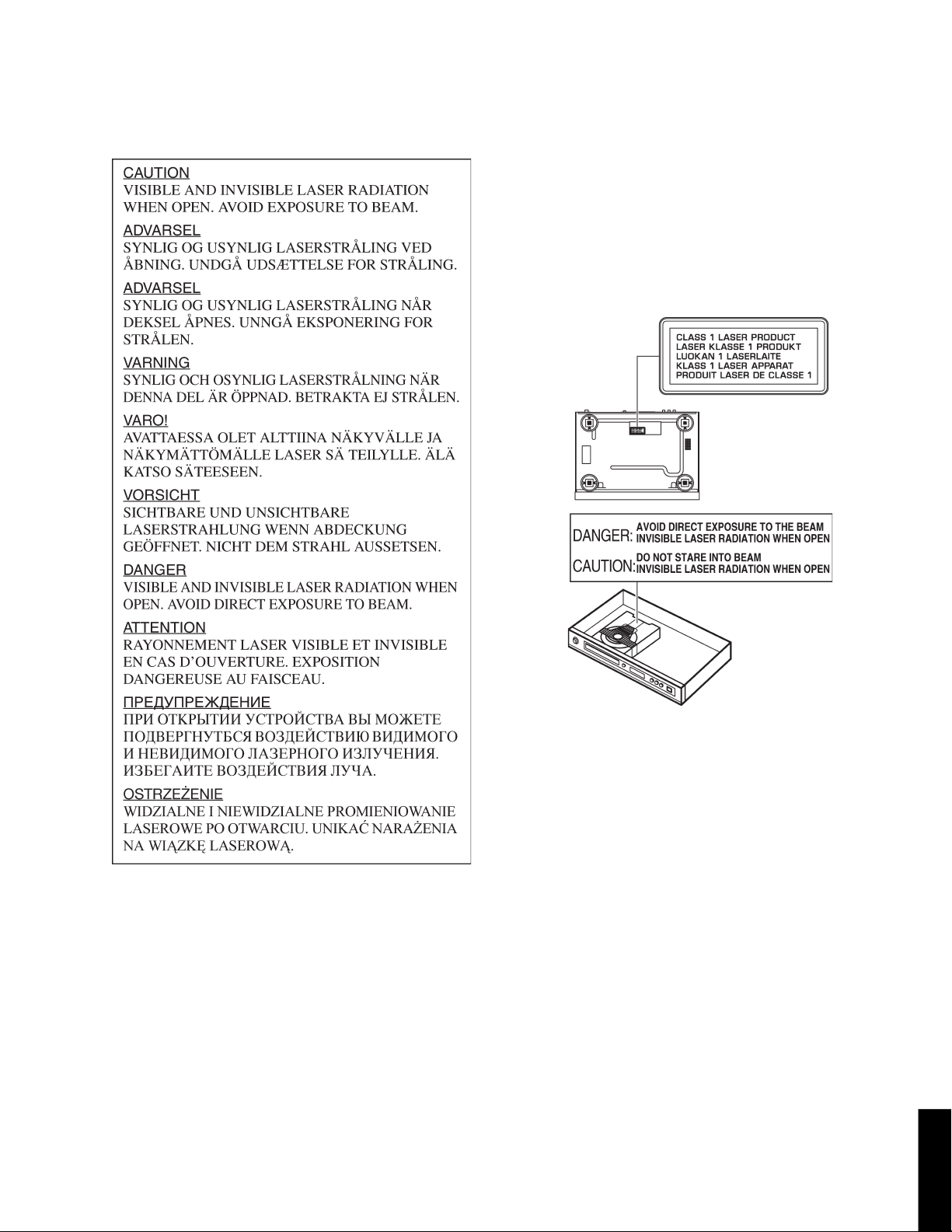
WARNING: Laser Safety
This product contains a laser beam component. This component may emit invisible, as well as visible radiation,
which may cause eye damage. To protect your eyes and skin from laser radiation, the following precautions must be
used during servicing of the unit.
1) When testing and/or repairing any component within the product, keep your eyes and skin more than 30 cm away from
the laser pick-up unit at all times. Do not stare at the laser beam at any time.
2) Do not attempt to readjust, disassemble or repair the laser pick-up, unless noted elsewhere in this manual.
3) CAUTION : Use of controls, adjustments or performance of procedures other than those specified herein may result in
hazardous radiation exposure.
Laser Emitting conditions:
1) When the Top Cover is removed, and the STANDBY/ON SW is turned to the "ON" position, the laser component will emit
a beam for several seconds to detect if a disc is present. During this time (5-10 sec.) the laser may radiate through the
lens of the laser pick-up unit. Do not attempt any servicing during this period!
If no disc is detected, the laser will stop emitting the beam. When a disc is loaded, you will not be exposed to any laser
emissions.
2) The laser power level can be adjusted with the VR on the pick-up PWB, however, this level has been set by the factory
prior to shipping from the factory. Do not adjust this laser level control unless instruction is provided elsewhere in this
manual. Adjustment of this control can increase the laser emission level from the device.
Laser Diode Properties
Type: Semiconductor laser GaAlAs
Wave length: 650 nm (DVD)
780 nm (VCD/CD)
Output Power: 7 mW (DVD)
10 mW (VCD/CD)
Beam divergence: 60 degree
2
DV-S6160
DVD-S661/
WARNING
The use of optical instruments with this product will increase eye hazard.
Repair handling should take place as much as possible with a disc loaded inside the player.
DVD-S661/DV-S6160
Warning for power supply
The primary side of the power supply carries live mains voltage when the player is connected to the mains even when
the player is switched off !
This primary area is not shielded so it is possible to touch copper tracks and/or components when servicing the player.
Service personnel have to take precautions to prevent touching this area or components in this area.
Note:
The screws on the DVD mechanism may never be touched, removed or re-adjusted.
Handle the DVD mechanism with care when the unit has to be exchanged!
The DVD mechanism is very sensitive for dropping or giving shocks.
3
DVD-S661/
DV-S6160
DVD-S661/DV-S6160
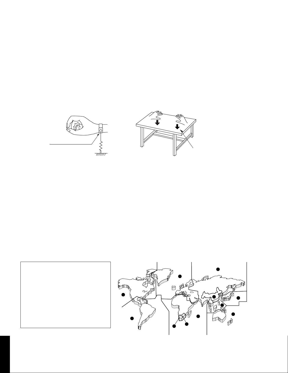
■ PREVENTION OF ELECTROSTATIC DISCHARGE
The laser diode in the DVD mechanism may be damaged due to static electricity from clothes or the human body. Use caution
to prevent electrostatic damage when servicing or handling the DVD-mechanism.
1. Grounding for electrostatic damage prevention
Some devices, such as the DVD player, use an optical pickup (laser diode) that will be damaged by static electricity in the
working environment. Only attempt service after ensuring that all grounding procedures have been completed.
1. Worktable grounding
Put a grounded conductive material (sheet) or iron sheet on the area where the optical pickup is placed.
2. Human body grounding
Use an anti-static wrist strap to discharge the static electricity from your body.
Anti-static wrist strap
1M-ohms
Conductive material
(sheet) or steel sheet
2. Handling Precautions for DVD mechanism
1. Handle the DVD mechanism gently, as it is an extremely high-precision assembly.
2. The flexible cable lines may break if an excessive force is applied to it. Use caution when handling the cable.
3. The semi-fixed resistor for laser power adjustment should not be adjusted. Do not turn the resistor.
■ LOCALE MANAGEMENT INFORMATION
Locale Management Information : This DVD player is designed and manufactured to respond to the Locale
Management Information that is recorded on a DVD disc. If the Locale number described on the DVD disc does not
correspond to the Locale number of this DVD player, this DVD player cannot play this disc.
This product incorporates copyright protection technology that is protected by
method claims of certain U.S. patents and
other intellectual property rights owned by
Macrovision Corporation and other rights
owners. Use of this copyright protection
technology must be authorized by
Macrovision Corporation, and is intended
for home and other limited viewing uses
only unless otherwise authorized by
Macrovision Corporation. Reverse engineering or disassembly is prohibited.
2
1
4
2
5
5
5
6
3
2
4
4
DV-S6160
DVD-S661/
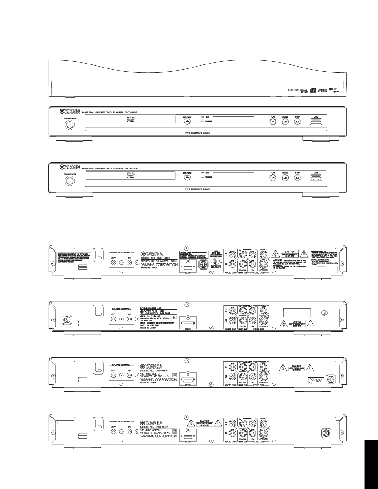
■ FRONT PANELS
DVD-S661 (U, K, A, L, P models)
DV-S6160 (U model)
DVD-S661/DV-S6160
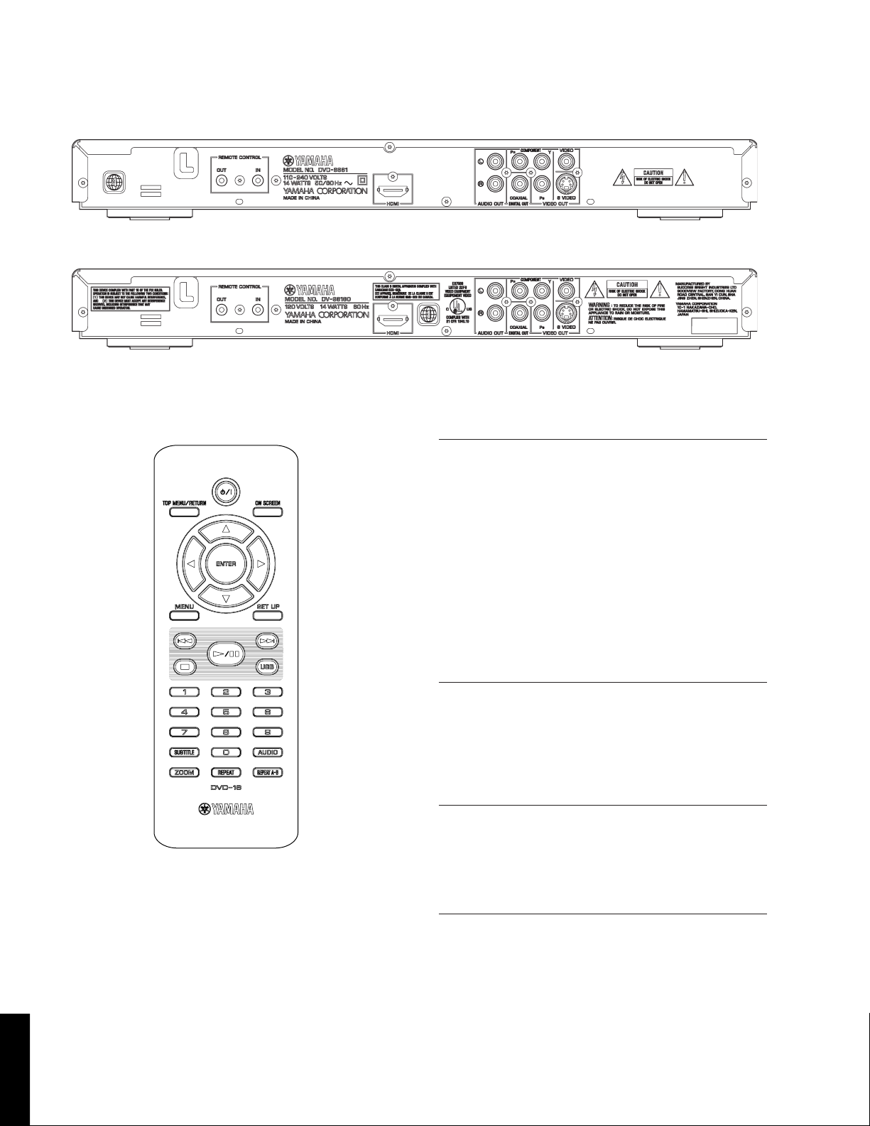
■ REAR PANELS
DVD-S661 (U model)
DVD-S661 (K model)
DVD-S661 (A model)
DVD-S661 (L model)
5
DVD-S661/
DV-S6160
DVD-S661/DV-S6160
DVD-S661 (P model)
DV-S6160 (U model)
■ REMOTE CONTROL PANEL
■ SPECIFICATIONS
PLAYBACK SYSTEM
DVD Video, VR (Video Recording) format (DVD-RW)
DVD-R, DVD-RW, DVD-R DL
DVD+R, DVD+RW, DVD+R DL
Video CD, SVCD
CD
PICTURE CD
CD-R, CD-RW
MP3 (ISO 9660) fs 32, 44.1, 48 kHz / 96, 128, 256,
320 kbps (Constant bit rate)
WMA fs 44.1 kHz, 62 to 192 kbps /
fs 48 kHz, 128 to 192 kbps (Constant
bit rate)
DivX
JPEG 3072 x 2048 dpi or less
VIDEO PERFORMANCE
Video (CVBS) output 1 Vpp into 75 ohms
S-Video output Y: 1 Vpp into 75 ohms
C: 0.3 Vpp into 75 ohms
Component video output Y: 1 Vpp into 75 ohms
PB/PR: 0.7 Vpp into 75 ohms
HDMI upscaling 720 p, 1080 i
AUDIO FORMAT
Digital
Dolby Digital, DTS, MPEG
Compressed digital
PCM fs 44.1, 48, 96 kHz / 16, 20, 24 bits
Analog sound Stereo
6
DV-S6160
DVD-S661/
AUDIO PERFORMANCE
DA converter 24 bits
Signal to noise (1 kHz) 105 dB
Dynamic range (1 kHz) 97 dB
DVD fs 96 kHz 2 Hz to 44 kHz
fs 48 kHz 2 Hz to 22 kHz
SVCD fs 48 kHz 2 Hz to 22 kHz
fs 44.1 kHz 2 Hz to 20 kHz
CD/VCD fs 44.1 kHz 2 Hz to 20 kHz
Distortion and noise 0.0035 %
(1 kHz)
DVD-S661/DV-S6160
310
(12-3/16")
6
(1/4")
318
(12-1/2")
2
(1/16")
435 (17-1/8")
6
(1/4")
45
(1-3/4")
51
(2")
MULTIMEDIA (USB) APPLICATIONS
Connections USB mass storage class device
Playback formats
(USB device)
MP3 fs 32, 44.1, 48 kHz / 96, 128, 256,
320 kbps (Constant bit rate)
WMA fs 44.1 kHz, 62 to 192 kbps /
fs 48 kHz, 128 to 192 kbps (Constant
bit rate)
DivX 3 Mbps or less
JPEG 3072 x 2048 dpi or less
Supported USB devices FLASH memory
(FAT16 or FAT32 format) Card reader (up to 6 slots)
Portable audio player
External hard disk drive (80 GB or less)
TV STANDARD (PAL/50 Hz) (NTSC/60 Hz)
Number of lines 625 525
Playback Multistandard (PAL/NTSC)
CONNECTIONS
Video output RCA/Phono x 1 (yellow)
S-video output Mini DIN, 4 pins x 1
Component video output
Y output RCA/Phono x 1 (green)
PB output RCA/Phono x 1 (blue)
PR output RCA/Phono x 1 (red)
Audio output (L+R) RCA/Phono x 1 pair (white/red)
Digital output
Coaxial RCA/Phono x 1
IEC60958 for CDDA, LPCM / IEC61937
for MPEG 1/2, Dolby Digital and DTS
HDMI (HDMI 1.0) Type A x 1
USB Type A x 1
Remote control
Input 3.5 mm mini jack x 1
Output 3.5 mm mini jack x 1
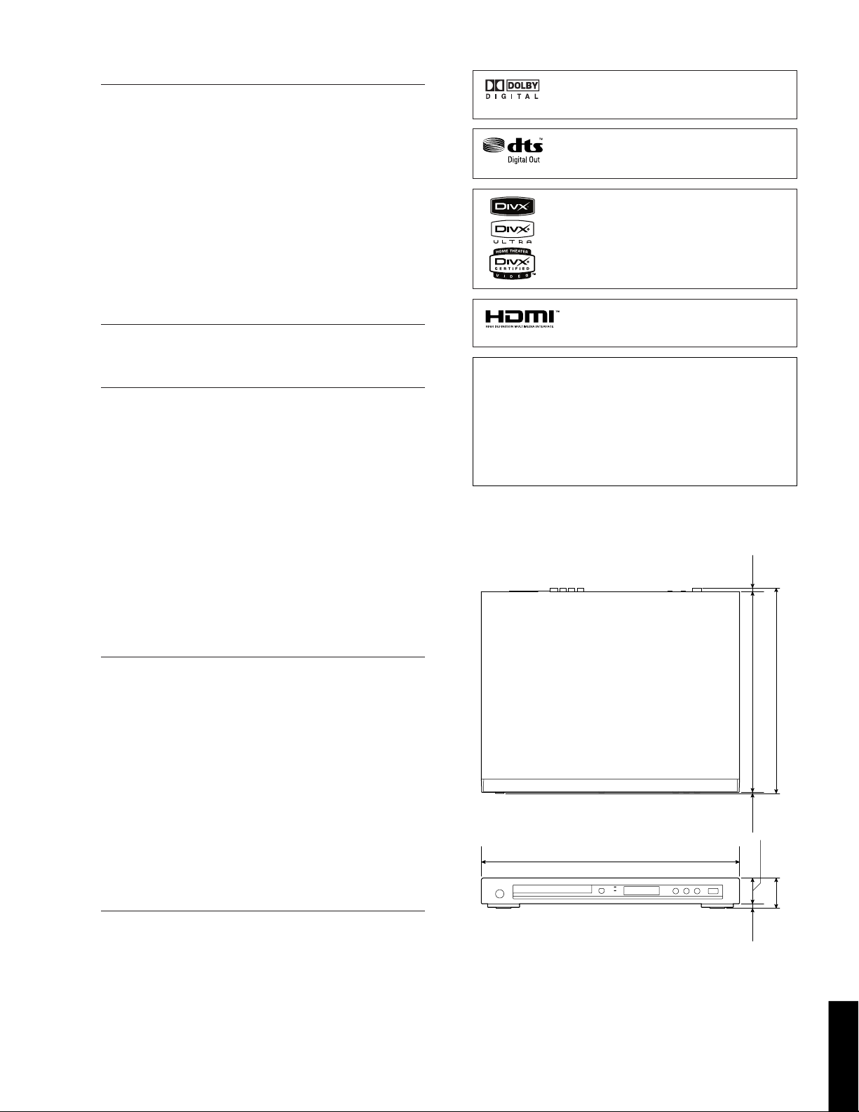
Manufactured under license from Dolby Laboratories. “Dolby”, “Pro Logic” and the double-D
symbol are trademarks of Dolby Laboratories.
“DTS” and “DTS Digital Out” are registered
trademarks of DTS, Inc.
DivX, DivX Ultra Certified, and associated
logos are trademarks of DivX, Inc. and are
used under license.
HDMI, the HDMI logo and High Definition
Multimedia Interface are trademarks or registered trademarks of HDMI Licensing LLC.
This product incorporates copyright protection technology
that is protected by method claims of certain U.S. patents
and other intellectual property rights owned by Macrovision
Corporation and other rights owners. Use of this copyright
protection technology must be authorized by Macrovision
Corporation, and is intended for home and other limited
viewing uses only unless otherwise authorized by Macrovision
Corporation. Reverse engineering or disassembly is prohibited.
• DIMENSIONS
GENERAL
Dimensions (W x H x D) 435 x 51 x 318 mm
(17-1/8" x 2" x 12-1/2")
Weight Approx. 2.6 Kg (5 lbs. 12 oz)
Finish
DVD-S661 Black color (U, A, P models)
Titanium color (U, K, L models)
Silver color (U model)
DV-S6160 Black color (U model)
Silver color (U model)
Power supply AC 120 V, 60 Hz (U model)
AC 110-240 V, 60 Hz (K model)
AC 110-240 V, 50/60 Hz
(A, L, P models)
Power consumption Approx. 14 W
Standby power consumption Less than 1 W
ACCESSORIES
* Specifications are subject to change without prior notice.
Remote control x 1
Battery (AAA, R03, UM-4) x 2
Audio / video cable (1.5 m) x 1
U ........ U.S.A. model
K ........ Korean model
A ........ Australian model
L ......... Singapore model
P ......... South America model
Unit: mm (inch)
7
DVD-S661/
DV-S6160
DVD-S661/DV-S6160
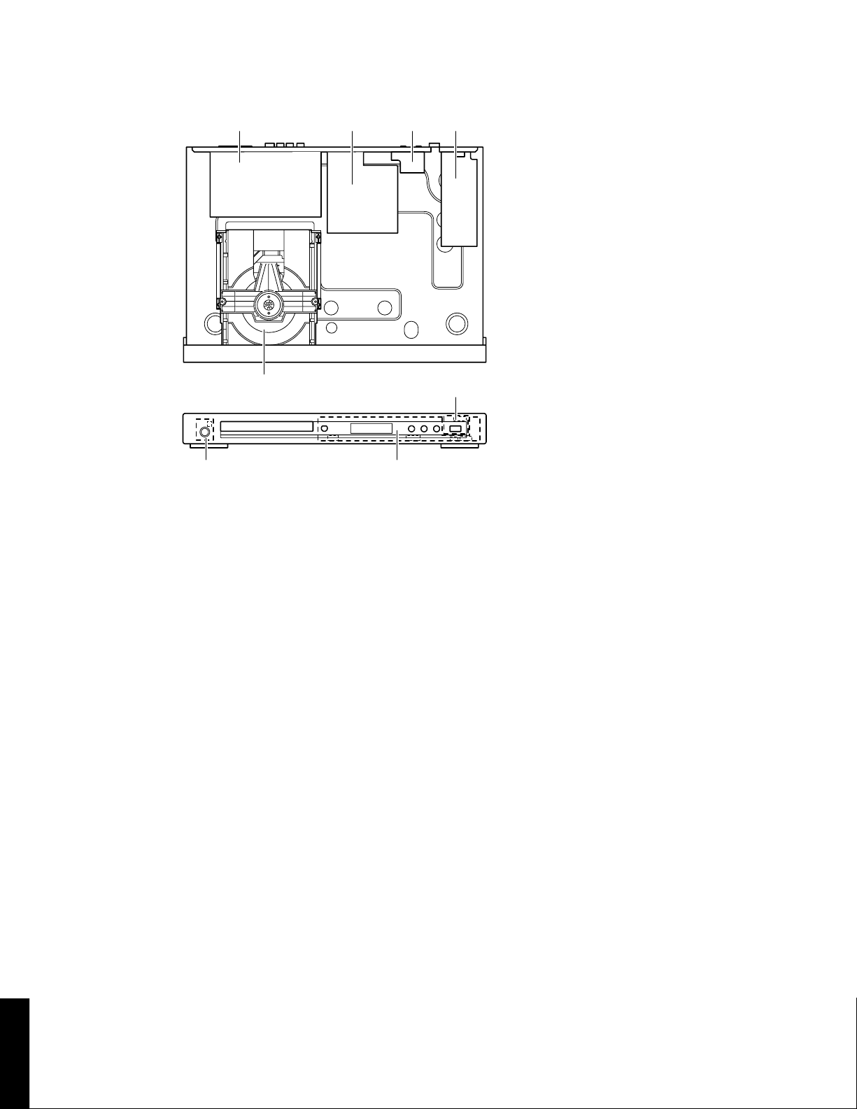
■ INTERNAL VIEW
1 432
1
AV P.C.B.
2
MONO P.C.B.
3
FRONT (4) P.C.B.
4
Power Supply Unit
5
DVD Mechanism
5
6 7
8
6
FRONT (2) P.C.B.
7
FRONT (1) P.C.B.
8
FRONT (3) P.C.B.
8
DV-S6160
DVD-S661/
DVD-S661/DV-S6160
■ REPAIR NOTES
None of the components of the following unit can be supplied separately.
Each unit must be replaced as a whole in case of a failure.
• DVD Mechanism
• MONO P.C.B.
• FRONT P.C.B.
• AV P.C.B.
• Power Supply Unit
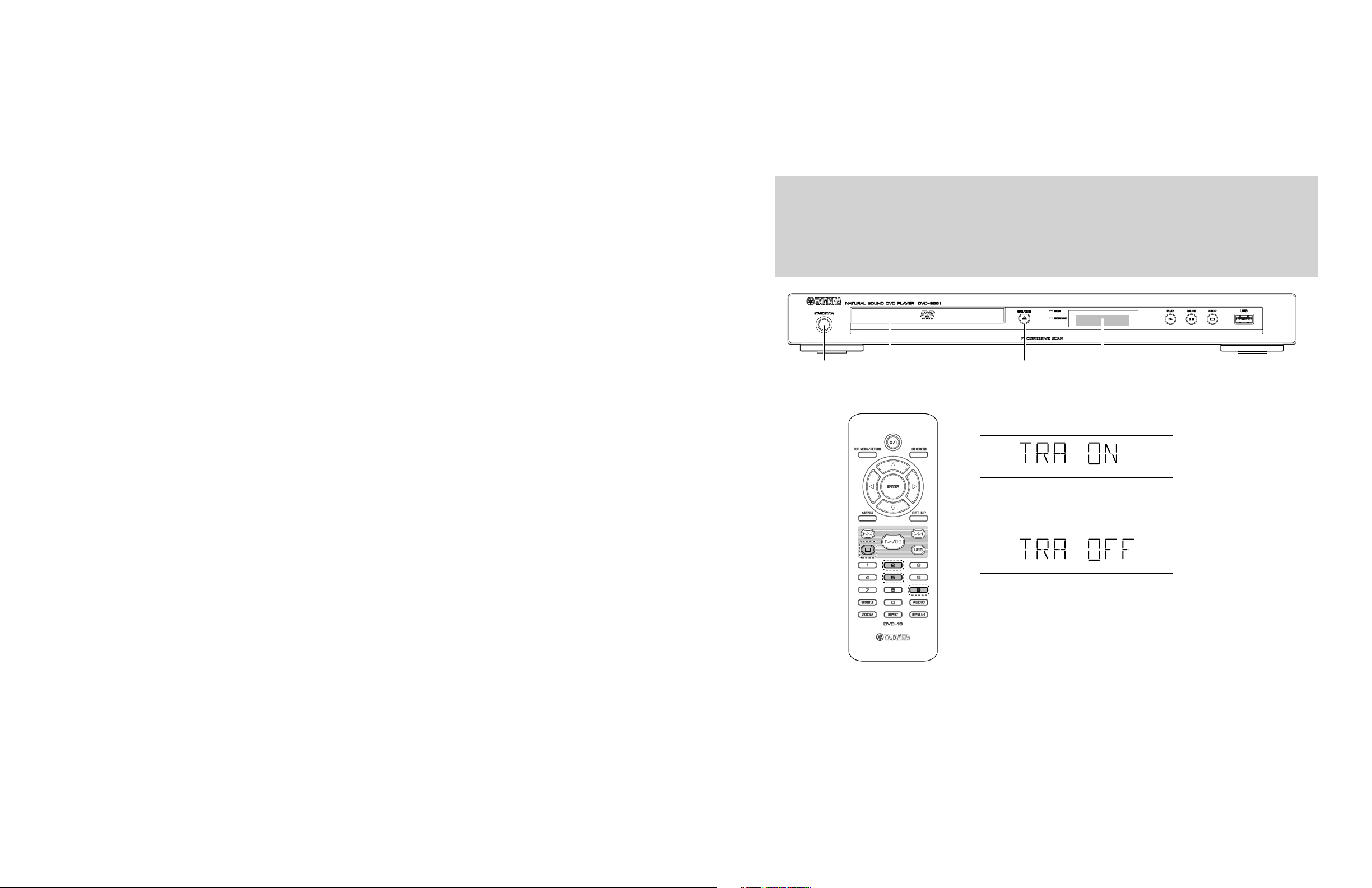
■ TRADE MODE
This unit provides TRADE mode which prevents the tray from opening even when the “OPEN/CLOSE” key is pressed.
• Activating TRADE mode
The power to the main unit should be turned on before activating the TRADE mode.
1. Press the “OPEN/CLOSE” key to open the tray. (Fig. 1)
2. Press the “2”, “5” and “9” keys on the remote control in that order. (Fig. 2)
3. “TRA ON” is displayed and TRADE mode is activated. About 2 seconds later, the tray is closed automatically. (Fig. 3)
Notes) • After activating TRADE mode, it is not possible to operate keys of the main unit as usual except the
following key.
“STANDBY/ON” key (Turn on the power only)
But operation with the remote control is available as usual.
• After TRADE mode is activated, initial settings for repeat reproduction of this unit are as follows.
DVD : RPT TT (repeat title)
VCD/SVCD/CD : RPT ALL (repeat all)
"STANDBY/ON" key Tray FL Display"OPEN/CLOSE" key
Fig. 1
TRADE mode display
Enter
Fig. 3
Cancel
Fig. 4
Fig. 2
• Canceling TRADE mode
The power to the main unit should be turned on before canceling TRADE mode.
1. Press and hold the “STOP” key on the remote control. (Fig. 2)
The tray opens after about 2 second.
2. Press the “2”, “5” and “9” keys on the remote control in that order. (Fig. 2)
3. “TRA OFF” is displayed and TRADE mode is cancelled. About 2 seconds later, the tray is closed automatically. (Fig. 4)
9
DVD-S661/DV-S6160
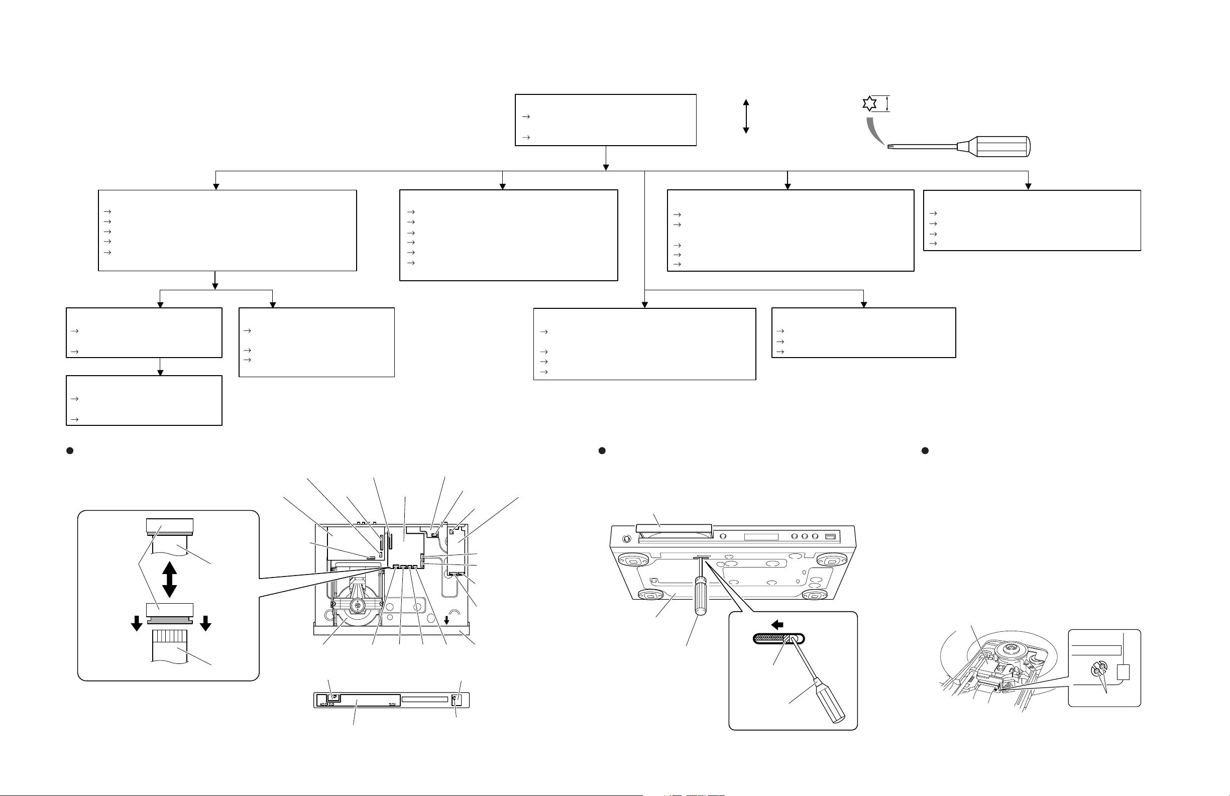
■ DISASSEMBLY PROCEDURES
See REPLACEMENT PARTS LIST for item numbers.
Top Cover [240]
Remove 5 screws [250] (2 on sides and 3 on
rear side).
Lift cover from rear side to remove.
Mounting
Dismounting
When disassembling, use T10 TORX screwdriver as shown below.
T10
2.7 mm
Front Panel [101]
Remove 4 cables connections. [1105] [1205] [CN3] [1301]
Open tray. (Fig. 2)
Unlock tray lid and close tray.
Remove 2 screws [251] (Front panel to frame).
Unlock front panel by releasing successively 4 snaps (2 on sides
and 2 on bottom side).
FRONT (3) P.C.B. [1001 (3)]
Remove 2 screws [260] (P.C.B. to front
panel).
Dismount P.C.B..
FRONT (1) P.C.B. [1001 (1)]
Remove 4 screws [260] (P.C.B. to front
panel).
Dismount P.C.B..
Cable connections
Lock
(MONO P.C.B.)
1101
Flexible flat cable
FRONT (2) P.C.B. [1001 (2)]
Remove 2 screws [260] (P.C.B. to front
panel).
Dismount P.C.B..
Remove cable connection [1200
(FRONT P.C.B.)].
1201
(AV P.C.B.)
1200
(AV P.C.B.)
1201
(MONO P.C.B.)
1100
MONO P.C.B.AV P.C.B.
DVD Mechanism [1300-1]
Solder the lands of the optical pick up. (Fig. 3)
Remove 3 cable connections [1101] [1102] [1103].
Open tray. (Fig. 2)
Unlock tray cover ass'y and close tray.
Remove 4 screws (DVD mechanism to frame).
Lift DVD mechanism up slightly and move it backward
to remove.
Remove 3 cable connections [1100] [1200 (AV P.C.B.)]
[1201 (AV P.C.B.)].
Remove 3 screws [260] (P.C.B. to rear panel).
Release 2 locking spacers (P.C.B. to frame).
Dismount P.C.B..
FRONT (4) P.C.B.
1301
Power supply unit
CN101
1207
1205
CN3
MONO P.C.B. [1003]
Solder the lands of the optical pick up. (Fig. 3)
Remove 7 cable connections
[1201 (MONO P.C.B.)] [1205] [1207].
Remove 3 screws [256] (P.C.B. to frame).
Remove screw [260] (P.C.B. to rear panel).
Dismount P.C.B..
AV P.C.B. [1002]
[1101] [1102] [1103] [1105]
FRONT (4) P.C.B. [1001 (4)]
Remove cable connection [1301].
Remove 2 screws [260] (P.C.B. to rear panel).
Dismount P.C.B..
How to manually eject the tray
a. Move the slider in the direction indicated with a flatblade
screwdriver until the tray is ejected.
b. Gently pull the tray out.
Tr ay
Power Supply Unit [1005]
Remove 3 cable connections [CN101] [CN1] [CN3].
Remove 2 screws [256] (P.C.B. to frame).
Release 2 locking spacers (P.C.B. to frame).
Dismount power supply unit.
Preventive measure for laser diode from
electrostatic breakdown
When replacing the MONO P.C.B. or DVD
mechanism, solder between lands of the optical
pick up P.C.B. to protect the laser diode against
electrostatic breakdown.
Notes
• Use an anti-static soldering iron to shortcircuit and unshort-circuit laser diode.
• After you have finished repairing, remove the
solder from the short-circuit location.
10
Unlock
Flexible flat cable
DVD mechanism Front panel1103110511021101
FRONT (1) P.C.B.
View A
A
FRONT (2) P.C.B.FRONT (3) P.C.B.
1200
(FRONT P.C.B.)
CN1
Bottom side
Flatblade screwdriver
Optical pick up
Slider
Solder
Flatblade screwdriver
Fig. 3Fig. 1 Fig. 2
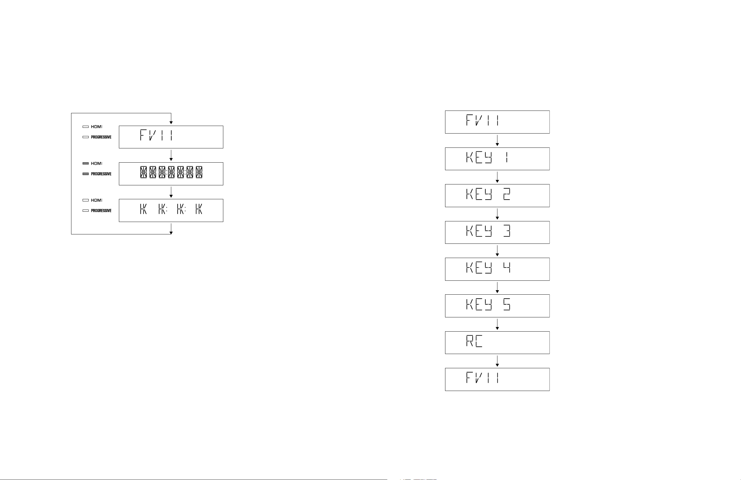
■ TEST MODE
• Starting Test Mode
a. Connect the power cable to the AC power outlet.
b. Press the “STANDBY/ON” key while simultaneously pressing “PAUSE” and “STOP” keys of the main unit.
At this time, keep pressing “PAUSE” and “STOP” keys for 8 seconds or longer.
c. The “FV xx” (firmware version) is displayed.
DVD-S661/DV-S6160
• Display Test
The display condition varies as shown below according to the “PLAY” key of the main unit.
(OFF)
(OFF)
(ON)
(ON)
(OFF)
(OFF)
Initial display
All segments on
Lighting of segments in lattice
• Panel Key Test
The display changes as shown below as the specified key is pressed.
Press “OPEN/CLOSE” key of the main unit.
Press “STANDBY/ON” key of the main unit.
Press “OPEN/CLOSE” key of the main unit.
Press “PLAY” key of the main unit.
Press “PAUSE” key of the main unit.
Press “STOP” key of the main unit.
Press “PLAY/PAUSE” key of the remote controller.
• Canceling Test Mode
Disconnect the power cable from the AC power outlet.
Initial display
11
ABCDEFGH I J
DVD-S661/DV-S6160
1
2
3
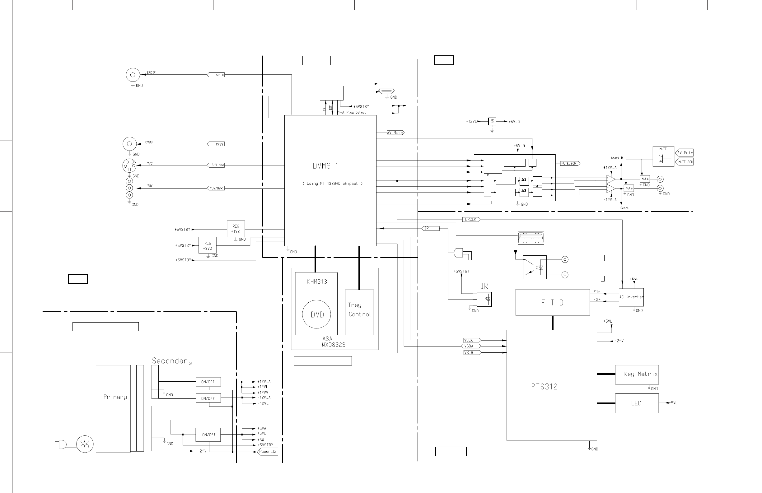
■ BLOCK DIAGRAM
DIGITAL OUT
COAXIAL
VIDEO
VIDEO OUT
S-VIDEO
COMPONENT
Y / P
B / PR
SC/SY
179,181
187
189,191
182,183,185
MONO
• See page 20-22 → SCHEMATIC DIAGRAM
7301
TZA1039HL
38,39
216
7108
+5D
+5STBY
206
211
215
98
99
209
210
197
HDMI
AV
• See page 23, 24 → SCHEMATIC DIAGRAM
+5D+5VL
L7805
IN
OUT
GND
7207
7216-7219
CLK
DIV.
MCLK
SCF
SCF
7208
DZFL
DZFR
AOUTL+
AOUTL-
AOUTR+
AOUTR-
16
15
12
11
10
9
AUDIO OUT
L / R
AK4385ET
CSN
6
CCLK
7
8
4
2
3
CDTI
LRCK
BICK
SDTI
uP
INTERFACE
DATA AUDIO
INTERFACE
PDN
5
DE-AMPHASIS
CONTROL
8 x
INTERPOLATOR
8 x
INTERPOLATOR
14 1
VDD
MOD
MOD
VSS
13
7112
+1V8
7113
4
DV3 3
47,48
109
3
D+/D-
7106
1
2
98
99
100
1521
+5V_STBY
7300
USB
14
IN
REMOTE
AV
• See page 23, 24 → SCHEMATIC DIAGRAM
INT_IR
OUT
GND
EXT_IR
7102
VS
32
SFH615
1100
OUT
CONTROL
7103-7105
5
Power Supply Unit
7100
8
5,6
9
DVD Mechanism
+12V
6
-12V
15-37
14,38
27
1105-1108
10-12
KEY1-3
6121,6122
41,42
+5V
AC IN
FRONT
7
12
• See page 25, 26 → SCHEMATIC DIAGRAM
ABCDEFGH I J
1
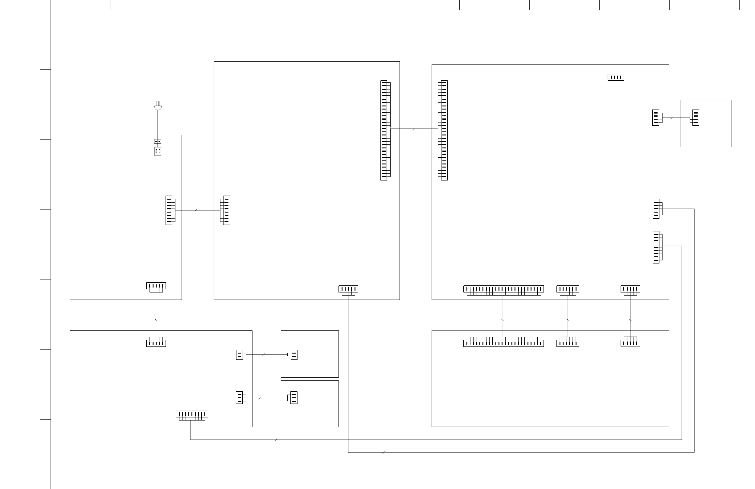
■ WIRING DIAGRAM
DVD-S661/DV-S6160
30FE-BT-VK-N
1100
MCLK
1
2
GND
BCLK
3
4
GND
5
AC IN
2
CN101
2P JST-VA/VH
1002
AV P.C.B.
3
1005
Power Supply Unit
+5Vstby
GND
+5Vstby
GND
+12VA
+5Vstby
-12VA
STBY_PSU
JST EH
CN1
1
2
3
4
5
6
7
8
8P
JST EH
1200
1
+5Vstby
2
GND
3
+5Vstby
4
GND
5
+12VA
6
+5Vstby
7
-12VA
8
STBY_PSU
LRCLK
GND
PCM_DATA0
PCM_DATA1
PCM_DATA2
GND
SPDIF
GND
CVBS
GND
Y_G
GND
B_Cb_Pb
GND
R_Cr_Pr
VSCK
VSDA
MUTE_CTRL1
GND
GND
GND
6
7
8
9
10
11
12
13
14
15
16
17
18
19
20
S0
21
S1
22
23
24
25
NC
26
Y
27
28
C
29
30
8100
FFC 30P/060/30P AD
4
30FE-BT-VK-N
1201
1
2
3
4
5
6
7
8
9
10
11
12
13
14
15
16
17
18
19
20
21
22
23
24
25
26
27
28
29
30
MCLK
GND
BCLK
GND
LRCLK
GND
PCM_DATA0
PCM_DATA1
PCM_DATA2
GND
SPDIF
GND
CVBS
GND
Y_G
GND
B_Cb_Pb
GND
R_Cr_Pr
S0
S1
VSCK
VSDA
MUTE_CTRL1
NC
Y
GND
C
GND
1003
MONO P.C.B.
DVM9.1
PH 1104
SERVICE
1
GND
TXD
432
NC
RXD
STBY_PSU
PCB_LRCLK
STBY_FRONT
+5VL
GND
+5STBY
+5Vstby
VSDA
VSCK
VSTB
GND
+5VL
GND
+5V
IR
P+
P-43
B4B-EH-A
1105
1
2
EH 1207
1
2
3GND
4
5
PH 1206
1
2
3
4
5
6
7
8
9
WH04D-1
1522
GND
4P
1
P+
2
P-43
+5V
1001
FRONT (3) P.C.B.
+5Vstby
GND
+12VA
-24V
CN3
JST EH
GND
12345
1201
B5B-EH-A
GND
+5VL
GND
12345
+5Vstby
STBY_PSU
GND-LD
1101
SFV24R-1STSFV24R-1ST
NC
LD-DVD
HFM
MD
LD-CD
VR-DVD
62354321
NC
VR-CD
SP-
SP+
L_SW
GND
SLED-
T-
RF
CD/DVD
VcFVCC
GND-PDBA
E
C
F-T+F+
D
181716
151413121110987
24
222120
19
PH 1102
SLED+
65432
1
LOAD+
PH 1103
TROUT
LOAD-
GND
TRIN
54321
5
12345
EH 1101
GND
5P
GND
+12VA
-24V
+5Vstby
STBY_FRONT
GND
EH 1104 EH 1200
1
2
2P
1001
12STBY_FRONT
GND
NC
LD-DVD
GND-LD
HFM
MD
62354321
LD-CD
VR-DVD
987
NC
VR-CD
8009
10
E
Vc
VCC
3139 241 00391
GND-PD
FFC 24P/280/24P AD
0.5mmP
1514131211
F
B
A
D
C
T-
RF
CD/DVD
24
22212019181716
F-
T+
F+
6P
PH
1
SP+
SP-
GND
L_SW
65432
SLED-
SLED+
PH
5P
LOAD-
LOAD+
GND
TROUT
54321
TRIN
FRONT (2) P.C.B.
6
1001
FRONT (1) P.C.B.
+5Vstby
123
PH 1102
VSTB
VSDA
VSCKIR+5VL
GND
4
567
PCB_LRCLK
STBY_FRONT
9
8
+5V_STBY
GND
EXT_IR 3
WH03D-1
1103
1
2
B3B-EH-A
1301
+5V_STBY
3P
1
GND
2
EXT_IR3
1004
DVD Mechanism
WXD8829
1001
FRONT (4) P.C.B.
9P
7
5P
13
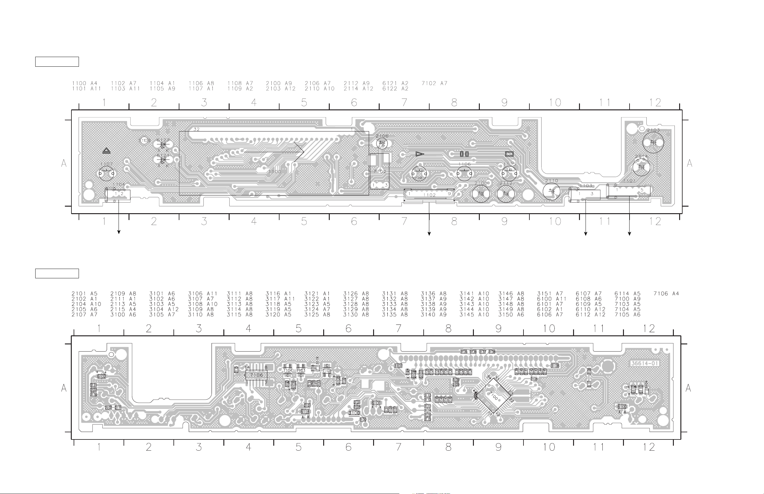
DVD-S661/DV-S6160
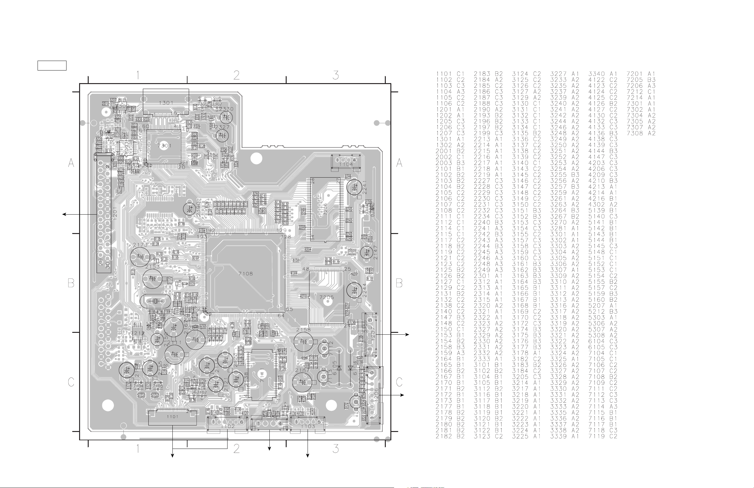
■ PRINTED CIRCUIT BOARDS
FOR INFORMATION ONLY (COMPONENT PARTS NOT AVAILABLE)
MONO
(Top view)
HDMI
The first digit of a component indicates the component type.
1xxx : Connector 3xxx : Resistor 5xxx : Coil 7xxx : IC, Transistor, FET
2xxx : Capacitor 4xxx : SMD jumper 6xxx : Diode 9xxx : Wire jumper
AV
(1100)
AV
(1201)
14
DVD Mechanism Unit
FRONT (3)
(1522)
FRONT (1)
(1102)
DVD Mechanism Unit
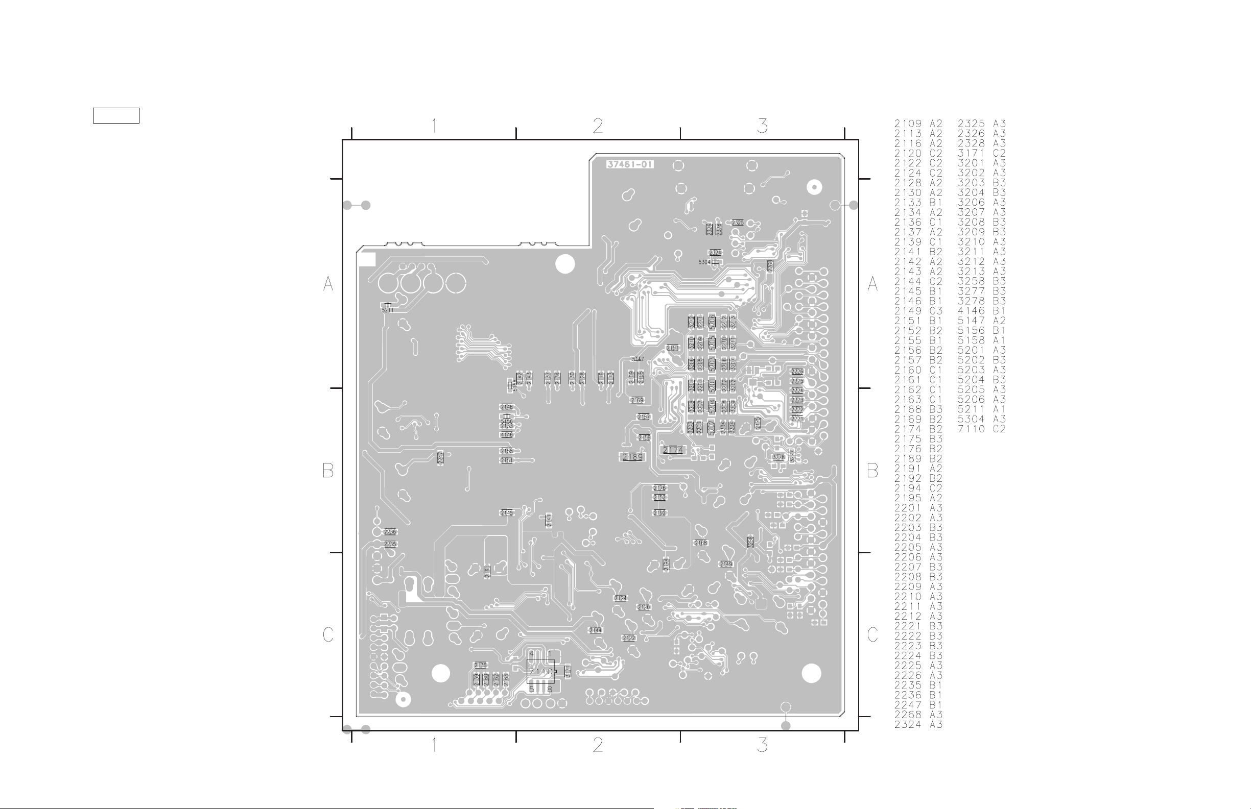
DVD-S661/DV-S6160
The first digit of a component indicates the component type.
1xxx : Connector 3xxx : Resistor 5xxx : Coil 7xxx : IC, Transistor, FET
2xxx : Capacitor 4xxx : SMD jumper 6xxx : Diode 9xxx : Wire jumper
MONO
(Bottom view)
15
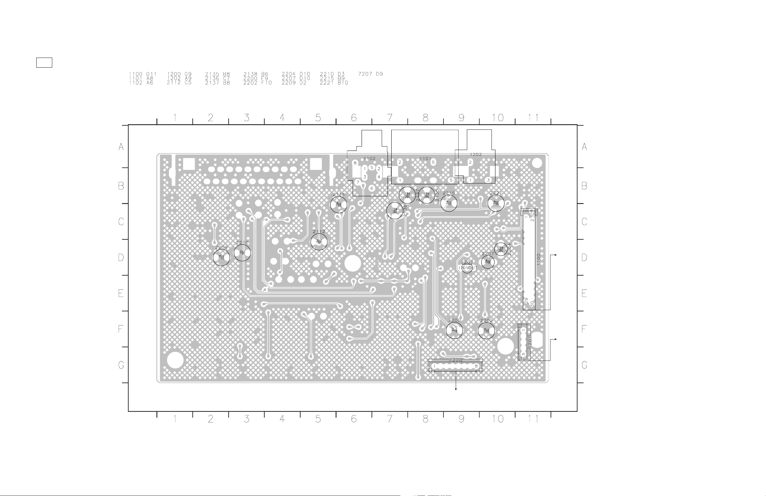
DVD-S661/DV-S6160
AV (Top view)
VIDEO/
S-VIDEO
COMPONENT
B, PR
Y, P
DIGITAL OUT
COAXIAL
The first digit of a component indicates the component type.
1xxx : Connector 3xxx : Resistor 5xxx : Coil 7xxx : IC, Transistor, FET
2xxx : Capacitor 4xxx : SMD jumper 6xxx : Diode 9xxx : Wire jumper
AUDIO OUT
L/R
Power Supply Unit (CN1)
(1201)
MONO
(1207)
MONO
16
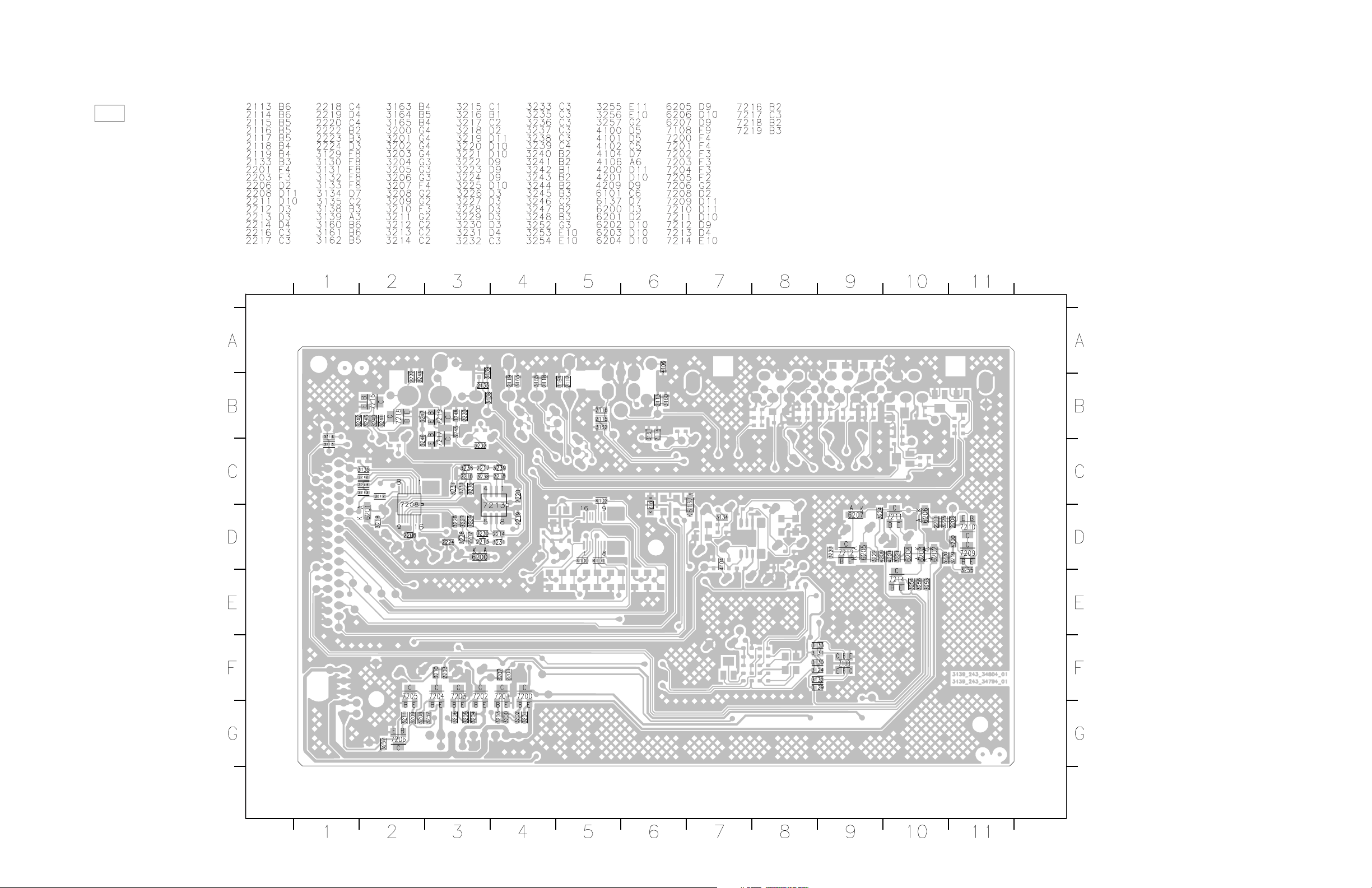
AV (Bottom view)
DVD-S661/DV-S6160
The first digit of a component indicates the component type.
1xxx : Connector 3xxx : Resistor 5xxx : Coil 7xxx : IC, Transistor, FET
2xxx : Capacitor 4xxx : SMD jumper 6xxx : Diode 9xxx : Wire jumper
17
DVD-S661/DV-S6160
The first digit of a component indicates the component type.
1xxx : Connector 3xxx : Resistor 5xxx : Coil 7xxx : IC, Transistor, FET
2xxx : Capacitor 4xxx : SMD jumper 6xxx : Diode 9xxx : Wire jumper
FRONT (1)
(Top view)
OPEN/CLOSE
PROGRESSIVE
FRONT (2)
(1200)
HDMI
LED
LED
PLAY PAUSE STOP
MONO
(1206)
FRONT (4)
(1301)
Power Supply Unit
(CN3)
FRONT (1)
(Bottom view)
18
 Loading...