

Yamaha DVD-S661 OWNER’S MANUAL
DVD PLAYER
LECTEUR DE DVD
DVD-S661
G

Important notes for users in the
U.K.
Mains plug
This apparatus is fitted with an approved 13
Amp plug. To change a fuse in this type of
plug proceed as follows:
1 Remove fuse cover and fuse.
2 Fix new fuse which should be a BS1362 5
Amp, A.S.T.
3 Refit the fuse cover.
If the fitted plug is not suitable for your jack
outlets, it should be cut off and an
appropriate plug fitted in its place.
If the mains plug contains a fuse, this should
have a value of 5 Amp. If a plug without a
fuse is used, the fuse at the distribution board
should not be greater than 5 Amp.
Note: The severed plug must be disposed to
avoid a possible shock hazard should it be
inserted into a 13 Amp jack elsewhere.
How to connect a plug
The wires in the mains lead are coloured with
the following code:
blue = neutral (N), brown = live (L).
• As these colours may not correspond with
the colour markings identifying the terminals
in your plug, proceed as follows:
– Connect the blue wire to the terminal
marked N or coloured black.
– Connect the brown wire to the terminal
marked L or coloured red.
– Do not connect either wire to the earth
terminal in the plug, marked E (or e) or
coloured green (or green and yellow).
Before replacing the plug cover, make certain
that the cord grip is clamped over the sheath
of the lead - not simply over the two wires.
Copyright in the U.K.
Recording and playback of material may
require consent. See Copyright Act 1956 and
The Performer’s Protection Acts 1958 to
1972.
VAR OIT US
Muiden kuin tässä esitettyjen toimintojen säädön tai
asetusten muutto saattaa altistaa vaaralliselle
säteilylle tai muille vaarallisille toiminnoille.
DK
Advarsel: Usynlig laserstråling ved åbning når
sikkerhedsafbrydere er ude af funktion. Undgå
utsættelse for stråling.
Bemærk: Netafbryderen STANDBY/ON er
sekundært indkoblet og ofbryder ikke strømmen fra
nettet. Den indbyggede netdel er derfor tilsluttet til
lysnettet så længe netstikket sidder i stikkontakten.
N
Observer: Nettbryteren STANDBY/ON er sekundert
innkoplet. Den innebygdenetdelen er derfor ikke frakoplet
nettet så lenge apparatet er tilsluttet nettkontakten.
S
Klass 1 laseraparat
Varning! Om apparaten används på annat sättþän i
denna bruksanvisning specificerats, kan användaren
utsättas för osynlig laserstrålning, som överskrider
gränsen för laserklass 1.
Observera! Strömbrytaren STANDBY/ON är
sekundärt kopplad och inte bryter inte strömmen
från nätet. Den inbyggda nätdelen är därför ansluten
till elnätet så länge stickproppen sitter i vägguttaget.
SF
Luokan 1 laserlaite
Varoitus! Laitteen käyttäminen muulla kuin tässä
käyttöohjeessa mainitulla tavalla saattaa altistaa
käyttäjän turvallisuusluokan 1 ylittävälle
näkymättömälle lasersäteilylle.
Oikeus muutoksiin varataan. Laite ei saa olla alttiina
tippu-ja roiskevedelle.
Toiminnanvalitsin STANDBY/ON on kytketty
toisiopuolelle, eikä se kytke laitetta irti sähköverkosta.
Sisäänrakennettu verkko-osa on kytkettynä
sähköverkkoon aina silloin, kun pistoke on pistorasiassa.
VAR O!
AVATTAESSA JA SUOJALUKITUS
OHITETTAESSA OLET ALTTIINA
NÄKYMÄTTÖMÄLLE LASERSÄTEILYLLE.
ÄLÄ KATSO SÄ TEESEEN.
VARNING!
OSYNLIG LASERSTRÅLNING NÄR DENNA
DEL ÄR ÖPPNAD OCH SPÄRREN ÄR
URKOPPLAD. BETRAKTA EJ STRÅLEN.
i
CAUTION
Use of controls or adjustments or performance of
procedures other than those specified herein may
result in hazardous radiation exposure.
AVERTISSEMENT
L’utilisation de commandes et l’emploi de
réglages ou de méthodes autres que ceux décrits
ci-dessous, peuvent entraîner une exposition à un
rayonnement dangereux.
VORSICHT
Die Verwendung von Bedienelementen oder die
Einstellung bzw. die Ausführung von anderen als
in dieser Anleitung beschriebenen Vorgängen
kann zu Gefährdung durch gefährliche Strahlung
führen.
OBSERVERA
Användning av reglage eller justeringar eller
utförande av åtgärder på annat sätt än så som
beskrivs häri kan resultera i farlig strålning.
ATTENZI ONE
L’uso di controlli, regolazioni, operazioni o
procedure non specificati in questo manuale
possono risultare in esposizione a radiazioni
pericolose.
PRECAUCIÓN
El uso de los controles, los ajustes o los
procedimientos que no se especifican enste
manual pueden causar una exposición peligrosa a
la radiación.
CAUTION
VISIBLE AND INVISIBLE LASER RADIATION
WHEN OPEN. AVOID EXPOSURE TO BEAM.
ADVARSEL
SYNLIG OG USYNLIG LASERSTRÅLING VED
ÅBNING. UNDGÅ UDSÆTTELSE FOR STRÅLING.
ADVARSEL
SYNLIG OG USYNLIG LASERSTRÅLING NÅR
DEKSEL ÅPNES. UNNGÅ EKSPONERING FOR
STRÅLEN.
VARNING
SYNLIG OCH OSYNLIG LASERSTRÅLNING NÄR
DENNA DEL ÄR ÖPPNAD. BETRAKTA EJ STRÅLEN.
VAR O!
AVATTAESSA OLET ALTTIINA NÄKYVÄLLE JA
NÄKYMÄTTÖMÄLLE LASER SÄ TEILYLLE. ÄLÄ
KATSO SÄTEESEEN.
VORSICHT
SICHTBARE UND UNSICHTBARE
LASERSTRAHLUNG WENN ABDECKUNG
GEÖFFNET. NICHT DEM STRAHL AUSSETSEN.
DANGER
VISIBLE AND INVISIBLE LASER RADIATION WHEN
OPEN. AVOID DIRECT EXPOSURE TO BEAM.
ATTENTION
RAYONNEMENT LASER VISIBLE ET INVISIBLE
EN CAS D’OUVERTURE. EXPOSITION
DANGEREUSE AU FAISCEAU.
ПРЕДУПРЕЖДЕНИЕ
ПPИ OTKPЫTИИ УCTPOЙCTBA BЫ MOЖETE
ПОДBEPГHУTБСЯ ВОЗДЕЙСТВИЮ BИДИMOГO
И HEBИДИMOГO ЛAЗEPHOГO ИЗЛУЧEHИЯ.
ИЗБЕГAИTE BOЗДЕЙСТВИЯ ЛУЧA.
OSTRZEŻENIE
WIDZIALNE I NIEWIDZIALNE PROMIENIOWANIE
LASEROWE PO OTWARCIU. UNIKAĆ NARAŻENIA
NA WIĄZKĘ LASEROWĄ.
LET OP
Gebruik van bedieningsorganen, instellingen of
procedures anders dan beschreven in dit
document kan leiden tot blootstelling aan
gevaarlijke stralen.
ПРЕДОСТЕРЕЖЕНИЕ
Использование органов управления или
произведение настроек или выполнение
процедур, не указанных в данной
инструкции, может отразиться на
выделении опасной радиации.
OSTRZEŻENIE
Używanie regulatorów i nastawień w inny
sposób lub wykonywanie procedur innych niż
tutaj podane może być przyczyną
niebezpiecznego promieniowania.
DANGER:
CAUTION:
AVOID DIRECT EXPOSURE TO THE BEAM
INVISIBLE LASER RADIATION WHEN OPEN
DO NOT STARE INTO BEAM
INVISIBLE LASER RADIATION WHEN OPEN
ii

CAUTION: READ THIS BEFORE OPERATING THIS UNIT.
1 To assure the finest performance, please read this
manual carefully. Keep it in a safe place for future
reference.
2 Install this unit in a well ventilated, cool, dry, clean
place — away from direct sunlight, heat sources,
vibration, dust, moisture, or cold. In a cabinet, allow
about 2.5 cm (1 inch) of free space all around this
unit for adequate ventilation.
3 Locate this unit away from other electrical
appliances, motors, or transformers to avoid
humming sounds.
4 Do not expose this unit to sudden temperature
changes from cold to hot, nor locate this unit in an
environment with high humidity (i.e., a room with a
humidifier) to prevent condensation inside this unit,
which may cause an electrical shock, fire, damage
to this unit, and/or personal injury.
5 Avoid installing this unit in a location where foreign
objects may fall onto this unit or where this unit
may be exposed to liquid dripping or splashing. On
the top of this unit, do not place:
– Other components, as they may cause damage
and/or discoloration on the surface of this unit.
– Burning objects (i.e., candles), as they may
cause fire, damage to this unit, and/or
personal injury.
– Containers with liquid in them, as they may
fall, spilling the liquid and causing an electrical
shock to the user and/or damage to this unit.
6 Do not cover this unit with a newspaper, tablecloth,
curtain, etc. in order not to obstruct heat radiation. If
the temperature inside this unit rises, it may cause
fire, damage to this unit, and/or personal injury.
7 Do not plug in this unit to a wall outlet until all
connections are complete.
8 Do not operate this unit upside-down. It may
overheat, possibly causing damage.
9 Do not use excessive force on switches, knobs and/
or cords.
10 When disconnecting the power cord from the wall
outlet, grasp the plug; do not pull the cord.
11 Do not clean this unit with chemical solvents; this
might damage the finish. Use a clean, dry cloth.
12 Use only the voltage specified on this unit. Using
this unit with a higher voltage than specified is
dangerous and may cause fire, damage to this unit,
and/or personal injury. Yamaha will not be held
responsible for any damage resulting from use of
this unit with a voltage other than as specified.
13 Do not attempt to modify or fix this unit. Contact
qualified Yamaha service personnel when any
service is needed. The cabinet should never be
opened for any reason.
14 When not planning to use this unit for long periods
of time (i.e., vacation), disconnect the AC power
plug from the wall outlet.
15 Be sure to read the “Troubleshooting” section on
common operating errors before concluding that
this unit is faulty.
16 Before moving this unit, press STANDBY/ON to
set the unit in standby mode, then disconnect the
AC power plug from the wall outlet.
17 Install this unit near the AC outlet and where the AC
power plug can be reached easily.
18 The batteries shall not be exposed to excessive heat
such as sunshine, fire or the like.
The unit is not disconnected from the AC power
source as long as it is connected to the wall outlet,
even if this unit itself is turned off. This state is called
the standby mode. In this state, this unit is designed
to consume a very small quantity of power.
WARNING
TO REDUCE THE RISK OF FIRE OR ELECTRIC
SHOCK, DO NOT EXPOSE THIS UNIT TO RAIN
OR MOISTURE.
LASER SAFETY
This unit employs a laser. Due to possible eye injury,
only a qualified service person should remove the cover
or attempt to service this device.
DANGER
This unit emits visible laser radiation when open. Avoid
direct eye exposure to beam.
When this unit is plugged into a wall outlet, do not
place your eyes close to the opening of the disc tray and
other openings or look inside.
This symbol mark is according to the
EU directive 2002/96/EC.
This symbol mark means that electrical
and electronic equipment, at their endof-life, should be disposed of
separately from your household waste.
Please act according to your local rules
and do not dispose of your old products
with your normal household waste.
iii

Contents
Contents
Introduction ..................................3
Supplied accessories .................................3
Region codes ..............................................3
Playable disc formats .................................3
Cleaning discs ............................................. 4
Patent information ......................................4
Functional Overview ....................5
Front panel ..................................................5
Rear panel .................................................... 6
Remote control ............................................ 7
Connections ..................................8
General notes on connections ..................8
Audio connections ......................................8
Digital connection ..............................................8
Analog connection ..............................................8
Video connections ......................................9
Component video jacks <A> ..............................9
S-video jack <B> ................................................9
Composite video jack <C> .................................9
SCART terminal <D> ........................................9
HDMI connection ....................................... 10
HDMI jack ........................................................10
Other connections ....................................11
USB port ...........................................................11
Remote control jacks ........................................11
Getting Started ...........................12
Step 1: Inserting batteries into
the remote control ....................................12
Using the remote control ..................................12
Step 2: Turning on the power ..................12
Step 3: Setting a TV type/display and
language .................................................... 13
Setting a color system for your TV ..................13
Setting an aspect ratio for your TV ..................13
Setting the OSD language ................................14
Setting the audio, subtitle and disc menu
languages (DVD-Video only) ..........................14
Playback Operation ................... 15
English
Basic operation ......................................... 15
Selecting a track/chapter ..................................15
Searching backward/forward ...........................15
Repeat/Shuffle functions ......................... 15
Repeat/Shuffle playback ..................................15
Repeating a section within a chapter/track ......16
Operations for video playback
(DVD/VCD/SVCD) ...................................... 16
Using the disc menu .........................................16
Playback in slow motion ..................................16
Zooming pictures in/out ...................................16
Resuming playback from the last
stopped point .................................................... 16
Using the on-screen display (OSD) .................17
Special DVD features ............................... 18
Playing by title ................................................. 18
Selecting an audio language/format
and subtitle language ........................................18
Special VCD/SVCD features ..................... 18
Using the playback control (PBC) menu .........18
Playing data discs (MP3/WMA/
JPEG/DivX) ................................................ 18
Selecting a folder and track/file .......................19
Special picture disc features ................... 19
Using the preview function ..............................19
Zooming pictures in/out ...................................19
Playback with multi-angles ..............................20
Playing MP3 music and JPEG picture
simultaneously .................................................20
Special DivX features ............................... 20
Using the interactive menu ..............................20
Selecting an audio/subtitle language ................20
Using a USB device .................................. 21
Supported USB devices ................................... 21
Playing data files ..............................................21
1 En

Contents
Setup Menu .................................22
General setup menu .................................22
Locking/Unlocking the disc for viewing ..........22
Dimming the front panel display ......................22
Programming disc tracks (except MP3/
WMA/JPEG/DivX) ..........................................22
OSD language ..................................................23
Setting the screen saver ....................................23
Setting the sleep timer ......................................24
Setting the auto standby function .....................24
Displaying the DivX
registration code ...............................................24
Audio setup menu .....................................24
Setting the analog output ..................................25
Setting the digital output ..................................25
Turning the HDMI audio on/off .......................25
Turning the night mode on/off .........................26
Setting the lip synchronization .........................26
Video setup menu .....................................26
TV type .............................................................26
Setting the TV display ......................................27
Turning the progressive scan function on/off ..27
Adjusting picture settings .................................28
Switching YUV/RGB .......................................29
Setting the HDMI video ...................................29
Preference setup menu ............................30
Audio, subtitle and disc menu ..........................30
Restricting playback with parental control .......30
Selecting playback of VR format .....................31
Selecting the MP3/JPEG menu ........................31
Displaying DivX external subtitle files ............32
Selecting the PBC (playback control)
function .............................................................32
Changing the password ....................................33
Resetting the system .........................................33
®
VOD
Language Codes ........................ 34
Troubleshooting ......................... 35
Glossary ...................................... 38
Specifications ............................. 40
2 En
Introduction
Introduction
Thank you for purchasing this unit. This
owner’s manual explains the basic operation
of this unit.
This manual is printed prior to production.
Design and specifications are subject to
change in part as a result of improvements,
etc. In case of differences between the manual
and the product, the product has priority.
Supplied accessories
• Remote control
• Two batteries (AAA, R03, UM-4) for the
remote control
• Audio pin cable
• Video pin cable
• Owner’s manual
Region codes
This unit is designed to support the region
management system. Check the regional code
number on the DVD disc package. If the
number does not match the region code of this
unit (see the table below or the back of this
unit), this unit may be unable to play the disc.
Destination
U.S.A.,
Canada
U.K.,
Europe
Asia,
Korea
Australia,
Central and
South America
Region
code of
this unit
1
2
3
4
Playable
discs
ALL
1
ALL
2
ALL
3
ALL
4
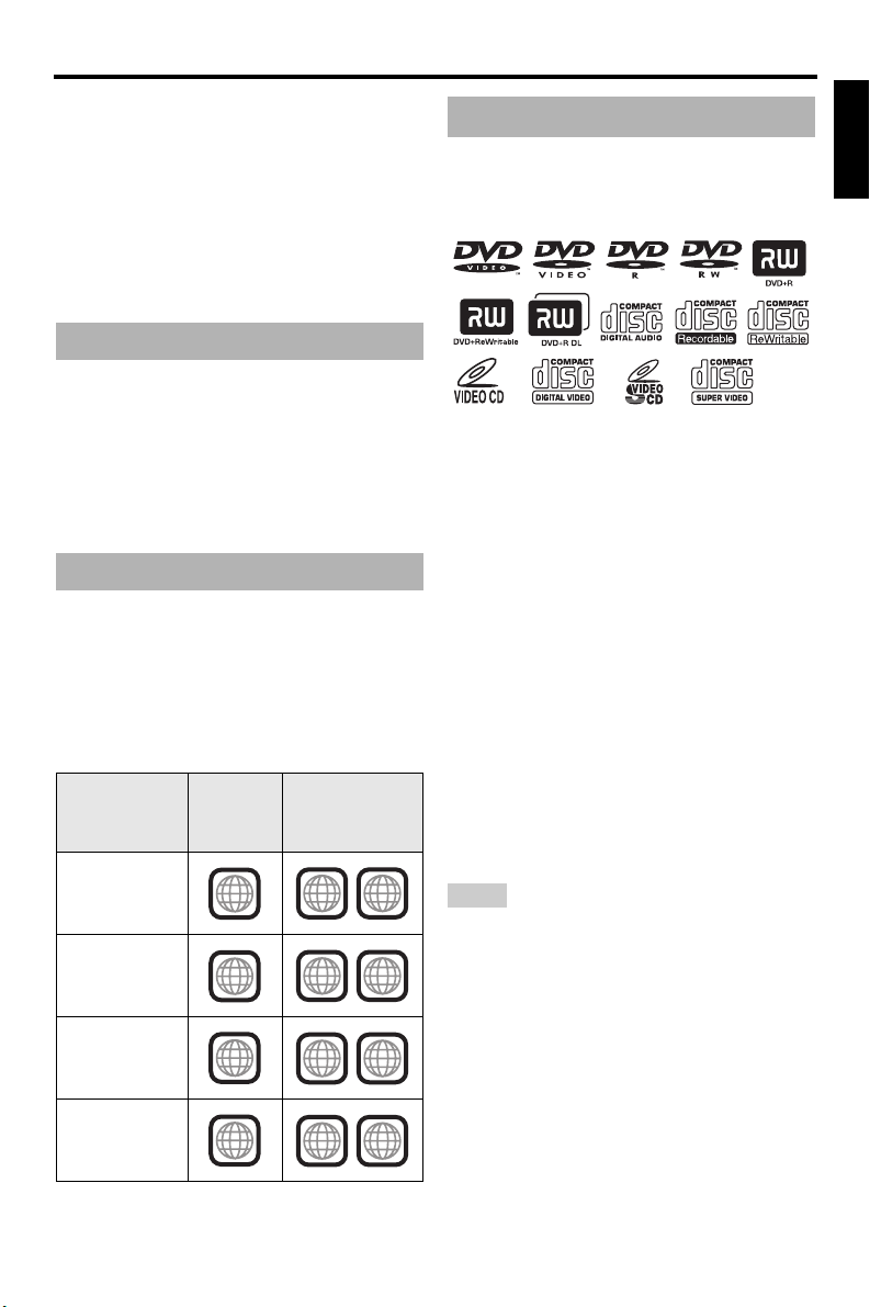
This unit can play the disc types associated
Playable disc formats
This unit is designed for use with discs having
the logos shown below. Do not attempt to load
any other type of disc into this unit.
This unit can play:
• DVD-R/RW/R DL and DVD+R/RW/R DL
discs recorded in DVD-Video compatible
format
• DVD-RW discs recorded in VR format
(compatible with CPRM)
• MP3, WMA and JPEG files recorded on
CD-R/RW, DVD-R/RW, DVD+R/RW and
USB
• KODAK picture CDs, FUJICOLOR CDs
• ISO 9660 Level1/Level2 for CD-R/RW
Up to 298 folders per disc/USB device and up
•
to 648 files per folder with up to 8 hierarchies
•DivX® files recorded on CD-R/RW,
DVD-R/RW, DVD+R/RW and USB
– Official DivX® Ultra Certified product
– Plays all versions of DivX
®
DivX
6) with enhanced playback of DivX®
media files and the DivX
Notes
• CD-R/RW, DVD-R/RW
R DL
cannot be played unless finalized.
• Progressive JPEG and copyright-protected WMA
files cannot be played with this unit.
• Only the first session of DVD-R/RW
DVD+R
/R DL
can be played.
• Some discs cannot be played depending on disc
characteristics or recording conditions.
• Do not use any non-standard shaped discs
(heart-shaped, etc.).
• Do not use discs with tape, seals, paste or many
scratches on their surface.
• For details about playable formats, see
“Specifications” on page 40.
®
video (including
®
Media Format
/R DL
and DVD+R/RW
/R DL and
English
/
3 En

Introduction
Cleaning discs
• When a disc becomes dirty, clean it with a cleaning cloth. Wipe the disc from the center out.
Do not wipe in a circular motion.
• Do not use solvents such as benzine, thinner, commercially available cleaners, or antistatic
spray intended for analog records.
Patent information
Manufactured under license from Dolby Laboratories. “Dolby”, “Pro Logic” and the double-D symbol are
trademarks of Dolby Laboratories.
“DTS” and “DTS Digital Out” are registered trademarks of DTS, Inc.
DivX, DivX Ultra Certified, and associated logos are trademarks of DivX, Inc. and are used under license.
HDMI, the HDMI logo and High Definition Multimedia Interface are trademarks or registered trademarks of
HDMI Licensing LLC.
This product incorporates copyright protection technology that is protected by method claims of certain
U.S. patents and other intellectual property rights owned by Macrovision Corporation and other rights
owners. Use of this copyright protection technology must be authorized by Macrovision Corporation, and
is intended for home and other limited viewing uses only unless otherwise authorized by Macrovision
Corporation. Reverse engineering or disassembly is prohibited.
4 En
Functional Overview
1 2354 6 7 8 9 0
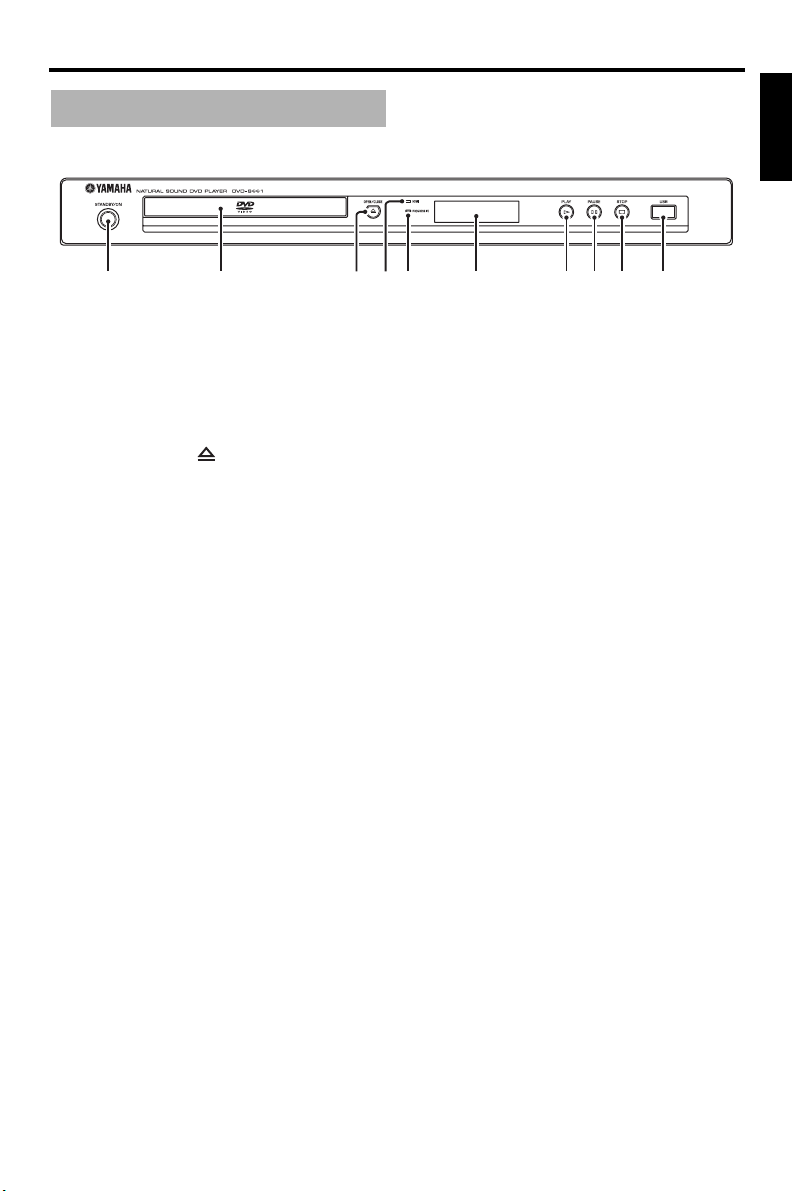
Front panel
Functional Overview
English
1 STANDBY/ON
Turns on this unit or sets it to the standby mode.
2 Disc tray
Loads a disc in the disc tray.
3 OPEN/CLOSE ( )
Opens or closes the disc tray.
4 HDMI indicator
Lights up when an HDMI component is
connected, and signals output via the HDMI
jack of this unit.
5 PROGRESSIVE indicator
Lights up when this unit enters the progressive
mode.
6 Front panel display
Shows the current status of this unit.
7 PLAY ( p )
Starts playback.
8 PAUSE ( )
Pauses playback.
9 STOP ( s )
Stops playback.
0 USB port
Connect to the USB port of your USB device
(see page 11).
5 En
Functional Overview
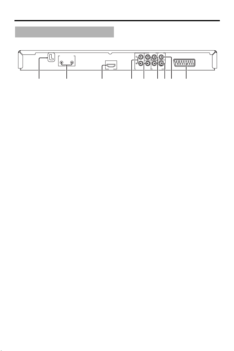
Rear panel
MAINS
REMOTE CONTROL
OUT
IN
COMPONENT VIDEO
P
R / CR
Y
PB / CB
S VIDEO
COAXIAL
AUDIO OUT
HDMI
VIDEO OUTDIGITAL OUT
AV
914567832
1 MAINS
Plug the power cable into the AC wall outlet.
2 REMOTE CONTROL (IN, OUT) jacks
Connect the REMOTE CONTROL (IN) jack of
this unit to the remote control output jack of
your Yamaha AV receiver.
Connect the REMOTE CONTROL (OUT) jack
of this unit to the remote control input jack of
your Yamaha component (see page 11).
3 HDMI jack
Connect to the HDMI input jack of your HDMI
component (see page 10).
4 AUDIO OUT (L, R) jacks
Connect to the audio input jacks of your AV
receiver or stereo system (see page 8).
5 DIGITAL OUT - COAXIAL jack
Connect to the coaxial input jack of your AV
receiver (see page 8).
6
VIDEO OUT - COMPONENT (Y, PB/CB,
P
R/CR) jacks
Connect to the component input jacks of your
AV receiver (see page 9).
7 VIDEO OUT - S VIDEO jack
Connect to the S-video input jack of your AV
receiver (see page 9).
8 VIDEO OUT - VIDEO jack
Connect to the composite video input jack of
your AV receiver (see page 9).
9 AV terminal
Connect to the SCART input terminal of your
TV (see page 9).
Caution: Do not touch the inner pins of the jacks on the rear panel of this unit.
Electrostatic discharge may cause permanent damage to this unit.
6 En
Remote control
1
2
3
4
5
6
0
q
w
e
r
Functional Overview
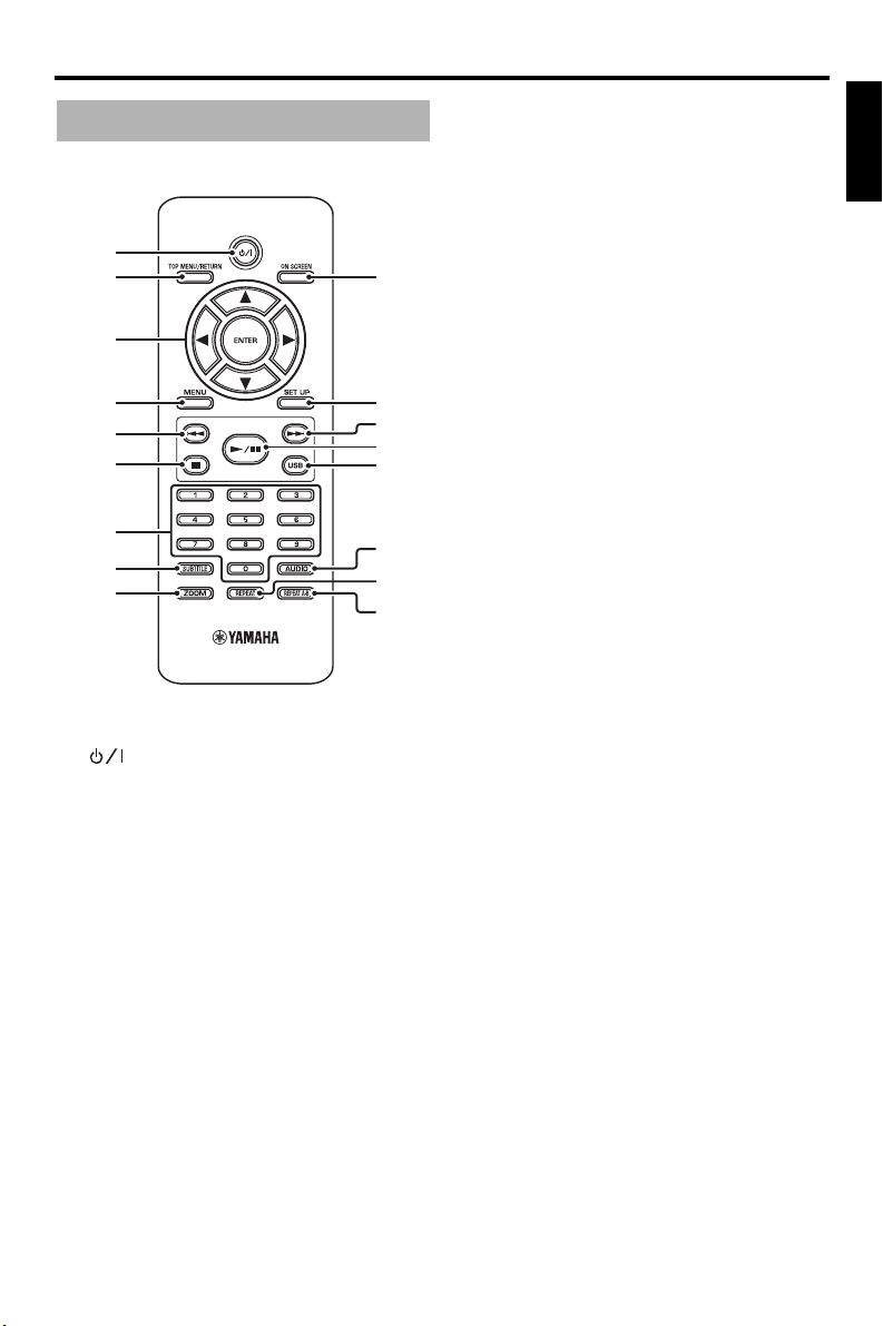
5 l22
Moves to the previous chapter or track.
Searches backward.*
6
7
Stops playback.
Opens the disc tray.*
7 Numeric buttons (0-9)
Selects numbered items in the currently
displayed menu.
8 SUBTITLE
Selects the subtitle language (see pages 18 and
20).
9 ZOOM
Enlarges the video image (see pages 16 and 19).
English
7
8
9
1
Turns on this unit or sets it to the standby mode.
2 TOP MENU/RETURN
Displays the top-level disc menu (DVD).
Moves back to the previous menu (DVD*/VCD)
(see page 18).
3 2 / 3 /5 /a
Selects an item in the currently displayed menu.
Search or slow playback.
ENTER
Confirms the menu selection.
4 MENU
Displays the menu of a disc (DVD/JPEG)
(see pages 16, 18, 19 and 20).
Switches PBC on or off (VCD) (see page 18).
t
y
u
0 ON SCREEN
Accesses or exits from the on-screen display
(OSD) menu of this unit (see page 17).
q SET UP
Accesses or exits from the setup menu of this
unit (see pages 13 and 22).
w 33l
Moves to the next chapter or track.
Searches forward.*
e 3 / 8
Starts or pauses playback.
r USB
Accesses the contents of the connected USB
device or exits from the USB mode (see
page 21).
t AUDIO
Selects the audio language or format (see
pages 18 and 20).
y REPEAT
Accesses or exits from the repeat/shuffle mode
(see page 15).
u REPEAT A-B
Repeats a specific segment (see page 16).
* Press and hold the button for about two seconds.
7 En

Connections
Connections
General notes on connections
Be sure to turn off this unit and unplug the
power cable before you make or change
connections.
• Depending on the component you want to
connect, there are various ways to make
connections. Possible connections are
described below.
• Refer to the manuals supplied with your
other components as necessary to make the
best connections.
• Do not connect this unit via your VCR. The
video quality could be distorted by the copy
protection system.
• Do not connect the audio out jack of this unit
to the phono in jack of your audio system.
Audio connections
Digital connection
This unit has a digital coaxial output jack.
Connect the DIGITAL OUT - COAXIAL jack
of this unit to your AV receiver equipped with
a Dolby Digital, DTS, or MPEG decoder
using a commercially available coaxial cable.
COMPONENT VIDEO
P
R / CR
Y
S VIDEO
COAXIAL
AUDIO OUT
PB / CB
VIDEO OUTDIGITAL OUT
C
C
AV receiver
AV
This unit
Notes
• You need to set [DIGITAL OUTPUT] to [ALL]
(see “DIGITAL OUTPUT” on page 25).
• If the audio format of the digital output does not
match the capabilities of your receiver, the
receiver produces a distorted sound or no sound
at all. Make sure to select the appropriate audio
format from the menu screen on the disc.
Pressing AUDIO on the remote control once or
more may change not only the audio languages
but also the audio format. The selected format
appears in the front panel display for several
seconds.
• If you want to enjoy Dolby Digital, DTS and
MPEG formats, you must connect this unit to an
AV receiver that supports these formats.
Analog connection
This unit has 2-ch analog output jacks.
Connect the AUDIO OUT (L, R) jacks of this
unit to the corresponding input jacks of your
audio component (such as a stereo amplifier)
using the supplied audio pin cable.
COMPONENT VIDEO
P
R / CR
Y
S VIDEO
COAXIAL
L
L
L
AUDIO OUT
R
Audio pin cable
(supplied)
R
R
PB / CB
VIDEO OUTDIGITAL OUT
Stereo
amplifier
Speakers
AV
This unit
8 En
Speakers
Connections
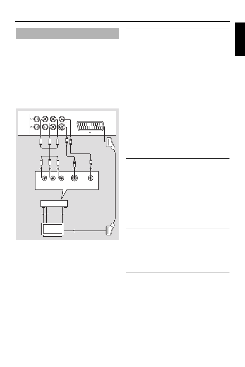
Video connections
If your AV receiver has video output jacks,
connect your receiver and then your TV so
that you can use one TV for several different
video sources (LD, VCR, etc.) by simply
switching the input source selector of your
receiver.
This unit has several types of video output
jacks. Use the one that corresponds to the
input jacks of the component to be connected.
COMPONENT VIDEO
R / CR
Y
P
PB / CB
S VIDEO
This unit
AUDIO OUT
VIDEO
OUT
VIDEO
COAXIAL
VIDEO OUTDIGITAL OUT
PB
PR
PB
PR
R
COMPONENT
VIDEO IN
AV receiver
COMPONENT
VIDEO OUT
COMPONENT
IN
VIDEO IN
TV
S
Y
V
Y
YPB/CBPR/C
S VIDEO
INPUT
S VIDEO
OUT
S VIDEO
IN
AV
Video pin cable
(supplied)
V
S
VIDEO
INPUT
<D><C><B><A>
Component video jacks <A>
Component video connections achieve higher
fidelity color reproduction than S-video
connections by transmitting video signals on
separate wires for luminance (Y: green) and
chrominance (P
B: blue, PR: red).
Connect the VIDEO OUT - COMPONENT
(Y, PB/CB, PR/CR) jacks of this unit to
component input jacks of your AV receiver
and then to those of your TV using a
commercially available component cable.
Observe the color of each jack when you make
connections.
If your receiver does not have component
output jacks, you can achieve a better video
image by connecting the component output
jacks of this unit directly to the component
input jacks of your TV.
S-video jack <B>
S-video connections achieve a clearer picture
than composite video connections by
transmitting video signals on separate wires
for luminance (Y) and chrominance (C).
Connect the VIDEO OUT - S VIDEO jack of
this unit to an S-video input jack of your AV
receiver and then to that of your TV using a
commercially available S-video cable.
Composite video jack <C>
Connect the VIDEO OUT - VIDEO jack of
this unit to a video input jack of your AV
receiver and then to that of your TV using the
supplied video pin cable.
English
SCART terminal <D>
If your TV has only a terminal for video input,
you can connect the TV directly to this unit.
Connect the AV terminal of this unit to
SCART input terminal of your TV using a
commercially available SCART cable.
9 En
Connections
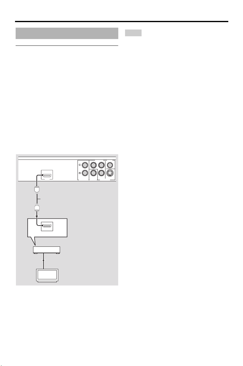
HDMI connection
HDMI jack
HDMI provides high quality digital audio and
video on a single connection.
Connect the HDMI jack of this unit to an
HDMI input jack of your AV receiver, and
then to that of your TV using a commercially
available HDMI cable.
If your receiver does not have an HDMI input
jack, you can achieve a better video image by
connecting the HDMI jack of this unit directly
to the HDMI input jack of your TV.
This unit can display High-Definition JPEG
images (720p or 1080i) when you connect this
unit to an HDTV via the HDMI jack. For
details, see “HD JPEG” on page 30.
COMPONENT VIDEO
R / CR
Y
P
PB / CB
HDMI
HDMI cable
AUDIO OUT
DIGITAL OUT
S VIDEOCOAXIAL
VIDEO OUT
This unit
Notes
• You need to set [HDMI AUDIO] (see page 25)
and [HDMI VIDEO] (see page 29).
• You need to make an appropriate audio
connections if the connected component does not
output audio signals (see “Audio connections” on
page 8).
• This unit is not compatible with HDCPincompatible HDMI or DVI components.
• You need a commercially available HDMI/DVI
conversion cable when you connect this unit to
other DVI components. In this case, the HDMI
jack of this unit does not output any audio
signals.
• Depending on the connected DVI component,
black and white in the image may not be distinct.
In that case, adjust the picture setting of the
connected DVI component.
• Do not disconnect or turn off the power of the
HDMI/DVI component connected to the HDMI
jack of this unit while data is being transferred.
Doing so may disrupt playback or cause noise.
• When connecting an HDMI component, refer to
the manual supplied with your component.
10 En
HDMI IN
AV receiver
HDMI OUT
HDMI IN
TV
 Loading...