

DVD AUDIO/VIDEO SA-CD PLAYER
LECTEUR DE DVD AUDIO/VIDEO SA-CD
DVD-S2700
G
STANDBY
ON
ON
POWER
AUDIO DIRECT
HDMI
OFF
CAUTION: READ THIS BEFORE OPERATING THIS UNIT.
CAUTION: READ THIS BEFORE OPERATING THIS UNIT.
1 To assure the finest performance, please read this manual
carefully. Keep it in a safe place for future reference.
2 Install this unit in a well ventilated, cool, dry, clean place
— away from direct sunlight, heat sources, vibration,
dust, moisture, or cold. In a cabinet, allow about 2.5 cm
(1 inch) of free space all around this unit for adequate
ventilation.
3 Locate this unit away from other electrical appliances,
motors, or transformers to avoid humming sounds.
4 Do not expose this unit to sudden temperature changes
from cold to hot, nor locate this unit in an environment
with high humidity (i.e., a room with a humidifier) to
prevent condensation inside this unit, which may cause an
electrical shock, fire, damage to this unit, and/or personal
injury.
5 Avoid installing this unit in a location where foreign
objects may fall onto this unit or where this unit may be
exposed to liquid dripping or splashing. On the top of this
unit, do not place:
– Other components, as they may cause damage and/
or discoloration on the surface of this unit.
– Burning objects (i.e., candles), as they may cause
fire, damage to this unit, and/or personal injury.
– Containers with liquid in them, as they may fall,
spilling the liquid and causing an electrical shock to
the user and/or damage to this unit.
6 Do not cover this unit with a newspaper, tablecloth,
curtain, etc. in order not to obstruct heat radiation. If the
temperature inside this unit rises, it may cause fire,
damage to this unit, and/or personal injury.
7 Do not plug in this unit to a wall outlet until all
connections are complete.
8 Do not operate this unit upside-down. It may overheat,
possibly causing damage.
9 Do not use excessive force on switches, knobs and/or
cords.
10 When disconnecting the power cord from the wall outlet,
grasp the plug; do not pull the cord.
11 Do not clean this unit with chemical solvents; this might
damage the finish. Use a clean, dry cloth.
12 Use only the voltage specified on this unit. Using this unit
with a higher voltage than specified is dangerous and may
cause fire, damage to this unit, and/or personal injury.
YAMAHA will not be held responsible for any damage
resulting from use of this unit with a voltage other than as
specified.
13 Do not attempt to modify or fix this unit. Contact
qualified YAMAHA service personnel when any service
is needed. The cabinet should never be opened for any
reason.
14 When not planning to use this unit for long periods of
time (i.e., vacation), disconnect the AC power plug from
the wall outlet.
15 Be sure to read the “TROUBLESHOOTING” section on
common operating errors before concluding that this unit
is faulty.
16 Before moving this unit, press STANDBY/ON to set the
unit in standby mode, then disconnect the AC power plug
from the wall outlet.
17 Install this unit near the AC outlet and where the AC
power plug can be reached easily.
18 The batteries shall not be exposed to excessive heat such
as sunshine, fire or the like.
The unit is not disconnected from the AC power source as
long as it is connected to the wall outlet, even if you turn
off this unit by STANDBY/ON on the front panel or
STANDBY ( ) on the remote control. This state is called
the standby mode. In this state, this unit is designed to
consume a very small quantity of power.
WARNING
TO REDUCE THE RISK OF FIRE OR ELECTRIC
SHOCK, DO NOT EXPOSE THIS UNIT TO RAIN OR
MOISTURE.
LASER SAFETY
This unit employs a laser. Due to possible eye injury, only a
qualified service person should remove the cover or attempt
to service this device.
DANGER
This unit emits visible laser radiation when open. Avoid direct
eye exposure to beam.
When this unit is plugged into a wall outlet, do not place your
eyes close to the opening of the disc tray and other openings
or look inside.
This symbol mark is according to the EU
directive 2002/96/EC.
This symbol mark means that electrical
and electronic equipment, at their end-oflife, should be disposed of separately from
your household waste.
Please act according to your local rules
and do not dispose of your old products
with your normal household waste.
iii

CONTENTS
English
INTRODUCTION 3
Playable disc formats.................................... 3
DVD region codes ............................................... 3
Patent information ......................................... 4
Cleaning discs ............................................... 4
Supplied accessories.................................... 4
FUNCTIONAL OVERVIEW 5
Front panel ..................................................... 5
Front panel display........................................ 6
Rear panel ...................................................... 7
Remote control .............................................. 8
CONNECTIONS 10
General notes on connections................... 10
Audio connections ...................................... 10
Connecting a stereo amplifier............................ 10
Connecting an AV receiver with 5.1ch/
digital input jacks .......................................... 10
Video connections....................................... 11
Connecting the power cable....................... 12
GETTING STARTED 13
Step 1: Inserting batteries into the
remote control .......................................... 13
Using the remote control ................................... 13
Step 2: Turning on the power..................... 13
Step 3: Setting a TV type............................. 14
Step 4: Setting a language preference ...... 15
Setting the OSD (On-Screen Display)
language......................................................... 15
Setting the audio, subtitle and disc menu
languages ........................................................... 15
DISC OPERATION 16
Basic operation ............................................ 16
Pausing playback................................................ 16
Selecting a track/chapter .................................... 16
Searching backward/forward ............................. 17
Repeat playback........................................... 17
Repeating playback ............................................ 17
Repeating a section (except DVD-Audio/
MP3/WMA/JPEG) ......................................... 17
Random playback
(except DVD/DivX/SA-CD)........................ 17
Program playback (CD) ................................. 18
Disc menu operation (DVD/VCD/SVCD)..... 18
Using the DVD menu......................................... 18
Using the Video CD playback control (PBC)
menu (VCD/SVCD) ....................................... 19
On-screen display (OSD) menu
(DVD/VCD/SVCD/SA-CD) ......................... 19
Using the OSD menu (DVD/VCD/SVCD/CD) .... 19
Displaying text information (SA-CD)................ 20
Zooming pictures (DVD-Video/VCD/
SVCD/DivX/JPEG)..................................... 20
Viewing angles (DVD-Video) ....................... 21
Audio and Subtitle languages (DVD-Video)
Selecting an audio language ............................... 21
Selecting a subtitle language.............................. 21
DivX external subtitle files.......................... 21
Changing pages (DVD-Audio)..................... 21
Group/File selection (DVD-Audio/DivX/
MP3/WMA/Kodak picture CD).................. 22
Selecting a group (DVD-Audio) ....................... 22
Selecting a file in a folder (DivX/MP3/WMA/
Kodak picture CD) ......................................... 22
Bonus group playback (DVD-Audio).......... 22
Changing the playback area and layer
(SA-CD)..................................................... 22
Multimedia file playback
(MP3/WMA/DivX/JPEG) ............................ 23
Displaying the thumbnail screen (JPEG) ........... 23
Rotating pictures (JPEG).................................... 23
... 21
1 En

Contents
SETUP MENU 24 LANGUAGE CODE LIST 36
Menu overview ............................................. 24
Setup menu operation................................. 25
General setup menu .................................... 26
Selecting DVD-Audio mode.............................. 26
Selecting SA-CD mode...................................... 26
Setting the OSD language.................................. 26
Restricting playback with parental control........ 26
Changing the parental password ........................ 26
Setting the screen saver...................................... 27
Setting the auto power function ......................... 27
Setting the sleep timer........................................ 27
Resetting the system .......................................... 27
Displaying the DivX® VOD registration code ... 27
Audio setup menu ....................................... 28
Setting the analog output ................................... 28
Setting the digital output.................................... 28
Setting the LPCM output................................... 28
Setting the night listening mode ........................ 28
Speaker setup menu.................................... 29
Setting speaker sizes .......................................... 29
Setting speaker distances ................................... 29
Setting speaker levels......................................... 30
Setting the SA-CD configuration....................... 30
Setting the cut-off frequency (SA-CD only)...... 30
Video setup menu........................................ 31
Setting the TV display ....................................... 31
Setting the TV type ............................................ 31
Selecting the black level
(U.S.A. and Canada models only) ................. 31
Selecting the closed caption
(U.S.A. and Canada models only) ................. 32
Setting the still mode ......................................... 32
Selecting the progressive scan function............. 32
Switching the SCART video out
(U.K. and Europe models only) ..................... 33
Adjusting picture settings .................................. 33
HDMI setup menu ........................................ 33
Setting the HDMI video..................................... 33
Selecting the wide screen format ....................... 34
Selecting the DVI output range ......................... 34
Setting the HDMI audio..................................... 35
DISC setup menu ......................................... 35
Selecting the default audio/subtitle/
DVD menu language ..................................... 35
Selecting an angle mark display ........................ 35
Selecting the PBC (playback control) function.... 35
Setting the duration for a slide show ..................35
TROUBLESHOOTING 37
GLOSSARY 39
SPECIFICATIONS 42
2 En
INTRODUCTION
INTRODUCTION
English
Thank you for purchasing this unit. This Owner’s Manual
explains the basic operation of this unit.
• Illustrations in this manual are based on the U.K. and
Europe models unless otherwise specified.
• Notes contain important information about safety and
operating instructions.
• y indicates a tip for your operation.
• This manual is printed prior to production. Design and
specifications are subject to change in part as a result of
improvements, etc. In case of differences between the
manual and the product, the product has priority.
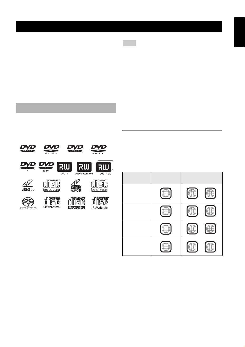
Playable disc formats
• This unit is designed for use with the following discs:
DVD-Video, DVD-Audio, DVD-R, DVD-RW,
DVD+R, DVD+RW, DVD+R DL, Video CD,
Super Video CD, Super Audio CD (SA-CD), Audio CD,
CD-R and CD-RW.
• This unit can play:
– MP3, WMA (except copyright-protected WMA) and
picture (Kodak, JPEG) files recorded on CD-R(W)/
DVD-R(W)/DVD+R(W)
– JPEG/ISO 9660 format
– Maximum 14 character display
®
–DivX
disc on CD-R(W)/DVD-R(W)/DVD+R(W)
– Official DivX® Certified product
– Plays all versions of DivX® video (including
®
6) with standard playback of DivX® media
DivX
files
Notes
• CD-R(W), DVD-R(W) and DVD+R(W) cannot be played
unless finalized.
• Copyright-protected WMA files cannot be played with this
unit.
• Some discs cannot be played depending on the recording
conditions, such as the PC environment and application
software. The characteristics and condition of some discs;
materials, scratches, curvature, etc., may result in playback
failure.
• Be sure to use only CD-R(W), DVD-R(W) and DVD+R(W)
discs made by reliable manufacturers.
• Do not use any non-standard shaped discs (heart-shaped, etc.).
• Do not use discs with tape, seals, or paste on their surface.
Doing so may damage this unit.
• Do not use discs affixed with labels printed by a commercially
available label printer.
DVD region codes
This unit is designed to support the region management
system. Check the regional code number on the DVD disc
package. If the number does not match the region code of
this unit (see the table below or the back of this unit), this
unit may be unable to play the disc.
Destination
U.S.A.
Canada
U.K.
Europe
Australia
China
Region code
of this unit
1
2
4
6
Playable discs
1
2
4
6
ALL
ALL
ALL
ALL
3 En
INTRODUCTION
Patent information
–
Manufactured under license from Dolby Laboratories.
“Dolby” and the double-D symbol are trademarks of
Dolby Laboratories.
“DTS” and “DTS Digital Surround” are registered
trademarks of Digital Theater Systems, Inc.
DivX, DivX Certified, and associated logos are
trademarks of DivX, Inc. and are used under license.
“DCDi” is a trademark of Faroudja, a division of Genesis
Microchip, Inc.
“HDMI”, the “HDMI” logo and “High Definition
Multimedia Interface” are trademarks or registered
trademark of HDMI Licensing LLC.
This product incorporates copyright protection
technology that is protected by method claims of
certain U.S. patents and other intellectual property
rights owned by Macrovision Corporation and other
rights owners. Use of this copyright protection
technology must be authorized by Macrovision
Corporation, and is intended for home and other limited
viewing uses only unless otherwise authorized by
Macrovision Corporation. Reverse engineering or
disassembly is prohibited.
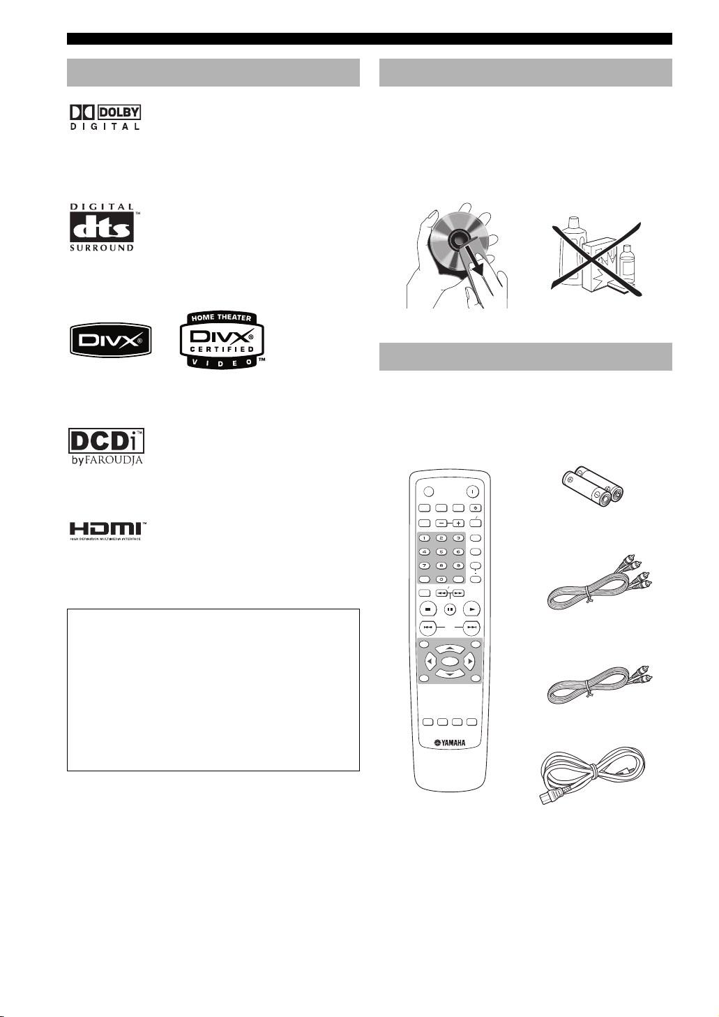
Cleaning discs
• When a disc becomes dirty, clean it with a cleaning
cloth. Wipe the disc from the center out. Do not wipe in
a circular motion.
• Do not use solvents such as benzine, thinner,
commercially available cleaners, or antistatic spray
intended for analog records.
Supplied accessories
Check your package to make sure it contains the following
items:
Remote
control
HDMI
AUDIO DIRECT STANDBY
ENTERCLEAR
SLOW SEARCH
PAUSE
SKIP
ON SCREENTOP MENU
ENTER
AUDIO ZOOM
ANGLE
POWER
MULTI 2CH
PLAY
LIGHT
DIMMER
GROUP PAGE
SETUP
STOP
MENU RETURN
SUBTITLE
PROG
RANDOM
REPEAT
A B
Batteries (x2)
(AAA, R03, UM-4)
Audio pin cable
Video pin cable
Power cable
4 En
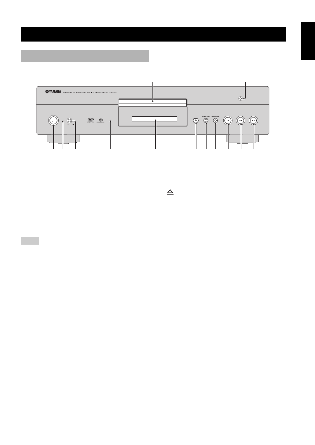
Front panel
5
FUNCTIONAL OVERVIEW
English
FUNCTIONAL OVERVIEW
1 2
AUDIO DIRECT
STANDBY
ON
ON
POWER
OFF
HDMI
3 64 7
1 Disc tray
Load a disc in the disc tray.
2 AUDIO DIRECT indicator
Lights up when you select the AUDIO DIRECT mode
by pressing AUDIO DIRECT on the remote control.
3 STANDBY/ON
Turns on this unit or sets it to the standby mode.
Notes
• This switch is operational only when POWER switch (5) is
pressed inward to the ON position.
• In the standby mode, this unit consumes a small amount of
power to receive infrared signals from the remote control.
4 POWER indicator
Lights up when this unit is on.
5 POWER switch
Press inward to the ON position to turn on the power of
this unit. Press again to release it outward to the OFF
position to turn off this unit.
8 9 0 w e
q
7 Front panel display
Displays playback information or settings.
8
Opens or closes the disc tray.
9 b/w
Searches backward.*
Moves to the previous chapter or track.
0 f/a
Searches forward.*
Moves to the next chapter or track.
q p
Starts playback.
w e
Pauses playback.
e s
Stops playback.
6 HDMI indicator
Lights up green when an HDMI component is
recognized by this unit and the HDMI mode is set to
on.
Lights up orange when no HDMI component is
recognized by this unit while the HDMI mode is set to
on.
* Press and hold the button for about three seconds.
5 En

FUNCTIONAL OVERVIEW
7
Front panel display
252134
SVCD WMA
MP3 JPEG
DVD AUDIO
SA-CD
P.SCAN TITLE GROUP CHP/ TRK MULTI D.MIX PROG. RANDOM ALL AD
DivX
6
1 P.SCAN indicator
Lights up when the progressive scan function is
activated.
2 Playback mode indicators
Display the icon for the selected playback mode.
3 Decoder indicators
Display the icon for the selected internal decoder.
4 MULTI indicator
Lights up when playing the multi-channel audio
source.
B
5 D.MIX indicator (DVD-Audio only)
Lights up when playing the disc that allows down
mixing of the multi-channel audio source.
6 Disc indicators
Display the icon for the disc type.
7 Information display
Displays various information such as a title/chapter/
track number or elapsed playing time.
y
You can adjust the brightness of the front panel display using
DIMMER on the remote control.
6 En

FUNCTIONAL OVERVIEW
q
98 0 w
Rear panel
145
CENTER
L
R
SUBWOOFER
SURROUND
AUDIO OUT DIGITAL
HDMI
1 AUDIO OUT (6ch discrete) jacks
Connect to the 6ch input jacks of your AV receiver.
2 AUDIO OUT (MIXED 2CH) jacks
Connect to the audio input jacks of your AV receiver or
stereo system.
3 DIGITAL (COAXIAL) jack
Connect to the coaxial input jack of your AV receiver.
263
COAXIAL
L
R
OPTICAL
MIXED 2CH
FRONT
AV
VIDEO
S VIDEO
IN
OUT
P
R / CR PB / CB Y
COMPONENT
VIDEO OUT
RS-232C
ON OFF
REMOTE CONTROL
7 MAINS
Connect the supplied power cable.
8 HDMI jack
Connect to the HDMI input jack of your HDMI
component.
9 DIGITAL (OPTICAL) jack
Connect to the optical input jack of your AV receiver.
English
7
MAINS
(U.K. and Europe models)
4 VIDEO OUT (VIDEO) jack
Connect to the composite video input jack of your AV
receiver.
5 REMOTE CONTROL (IN/OUT) connectors
Use in custom installations to transmit remote control
0 AV terminal
(U.K. and Europe models only)
Connect to SCART input terminal of your TV.
q VIDEO OUT (S VIDEO) jack
Connect to the S-video input jack of your AV receiver.
signals via cable connections.
w VIDEO OUT (COMPONENT) jacks
6 REMOTE CONTROL (RS-232C) terminal
(U.S.A., Canada, Australia, U.K. and Europe
Connect to the component input jacks of your AV
receiver.
models only)
Use as an expansion terminal for commercial use.
Consult your dealer for details.
■ Remote control connectors and RS-232C terminal
The REMOTE CONTROL (IN/OUT) connectors and the REMOTE CONTROL (RS-232C) terminal are used in
custom installation. Do not connect any cables to these connectors during normal use.
(For U.S.A., Canada, Australia, U.K. and Europe models, keep the RS-232C switch set to OFF.)
Caution: Do not touch the inner pins of the jacks on the rear panel of this unit. Electrostatic discharge
may cause permanent damage to this unit.
7 En
FUNCTIONAL OVERVIEW
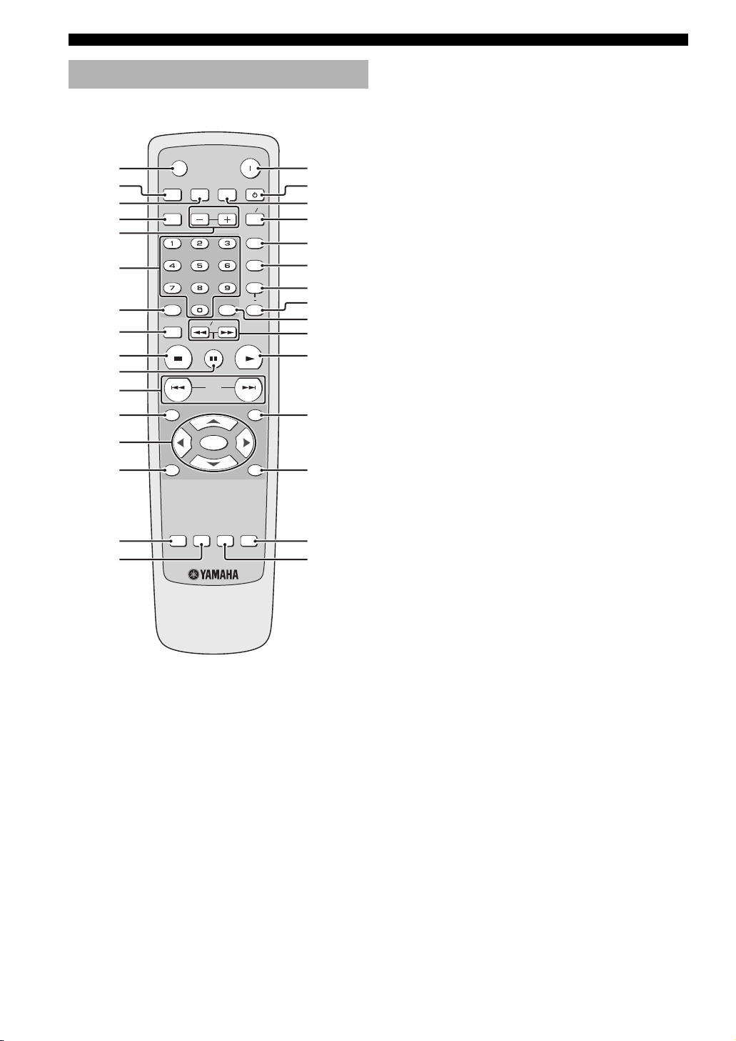
Remote control
LIGHT
1
2
3
4
5
6
7
8
9
0
q
w
e
r
DIMMER
GROUP PAGE
SETUP
STOP
MENU RETURN
HDMI
SLOW SEARCH
PAUSE
SKIP
ENTER
POWER
AUDIO DIRECT STANDBY
MULTI 2CH
PROG
RANDOM
REPEAT
A B
ENTERCLEAR
PLAY
ON SCREENTOP MENU
u
i
o
p
a
s
d
f
g
h
j
k
l
1 LIGHT
Lights up the remote control buttons.
2 DIMMER
Selects from three different levels of brightness for the
front panel display: medium, low and auto.
For auto setting, brightness is automatically set to low
only during playback.
3 HDMI
Switches the HDMI mode on or off.
4 GROUP
Selects the DVD-Audio group.
5 PAGE (+/–)
Selects the DVD-Audio still picture.
6 Numeric buttons (0-9)
Select numbered items in the currently displayed
menu.
7 CLEAR
Clear the mode or setting.
t
y
SUBTITLE
AUDIO ZOOM
ANGLE
;
z
8 SETUP
Accesses or exits from the setup menu of this unit.
7
9 STOP (
)
Stops playback.
0 PAUSE (
8
)
Pauses playback temporarily.
Frame-by-frame playback.
q SKIP (
l22 / 33l)
Moves to the previous/next chapter or track.
w TOP MENU
Displays the top-level disc menu.
8 En

FUNCTIONAL OVERVIEW
e Cursors ( / / / )
Selects an item in the currently displayed menu.
ENTER
Confirms the menu selection.
r MENU
Accesses the menu of a disc.
t SUBTITLE
Selects the subtitle language.
y AUDIO
Selects the audio language or format.
l
u POWER (
)
Turns on this unit.
i STANDBY ( )
Sets this unit to the standby mode.
o AUDIO DIRECT
Switches the video output on or off during playback.
This function is not available for HDMI output.
During the playback in the AUDIO DIRECT mode, the
front panel display goes out.
h SLOW / SEARCH (22 / 33)
Searches backward or forward.
3
j PLAY (
)
Starts playback.
k ON SCREEN
Accesses or exit from the on-screen display (OSD)
menu of this unit.
l RETURN
Returns to the previous setup menu.
; ZOOM
Enlarges the video image.
z ANGLE
Selects the DVD camera angle.
y
Two ENTER buttons (e and g) act in the same way.
English
p MULTI
/ 2CH
Selects a sound mode: Stereo or Multi-channel.
Changes the SA-CD playback area.
a PROG
Accesses the program setup menu to program disc
tracks or exit from its menu.
s RANDOM
Plays tracks in random order.
d REPEAT
Repeats the chapter, track, title, group or disc.
f A-B
Repeats a specific segment.
g ENTER
Confirms the menu selection.
9 En
CONNECTIONS
C
C
CONNECTIONS
General notes on connections
Be sure to turn off this unit and unplug the power supply
cable, before you make or change connections.
• Depending on the component you want to connect, there
are various ways to make connections. Possible
connections are described below.
• Refer to the manuals supplied with your other
components as necessary to make the best connections.
• Do not connect this unit via your VCR. The video
quality could be distorted by the copy protection system.
• Do not connect the audio out jack of this unit to the
phono in jack of your audio system.
Audio connections
This unit has digital coaxial, digital optical, analog 6ch
discrete, analog mixed 2ch and HDMI output jacks.
Connection depends on the availability of audio jacks on
your component.
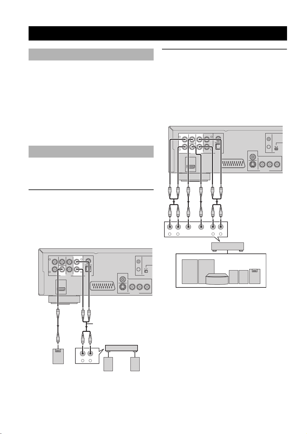
Connecting a stereo amplifier
Connect AUDIO OUT (MIXED 2CH) jacks of this unit to
the corresponding input jacks of your audio component
(such as a stereo amplifier) using the supplied audio pin
cable. You can connect a subwoofer to the
SUBWOOFER jack.
Connecting an AV receiver with 5.1ch/
digital input jacks
■ Analog connections
If you want to reproduce multi-channel Super Audio CD
(SA-CD) and DVD-Audio, connect AUDIO OUT (6ch
discrete) jacks of this unit to the corresponding input
jacks of your AV receiver using commercially available
audio pin cables.
This unit (U.K. and Europe models)
MIXED 2CH
COAXIAL
L
R
OPTICAL
SURROUND
RL
IN
ON OFF
OUT
VIDEO
AV
S VIDEO
R / CR PB / CB Y
P
COMPONENT
VIDEO OUT
REMOTE
FRONT
L
R
SURROUND
CENTER
RL
CENTER
FRONT
SUBWOOFER
AUDIO OUT DIGITAL
HDMI
SUBWOOFER
This unit (U.K. and Europe models)
MIXED 2CH
COAXIAL
L
R
OPTICAL
AV
CENTER
L
R
SUBWOOFER
SURROUND
AUDIO OUT DIGITAL
HDMI
FRONT
Audio pin cable
(supplied)
CD / DVD
RL
Subwoofer
Left
speaker
VIDEO
S VIDEO
Stereo
amplifier
IN
OUT
R / CR PB / CB Y
P
COMPONENT
VIDEO OUT
Right
speaker
AV receiver
Speakers
ON OFF
REMOTE
10 En
CONNECTIONS
E
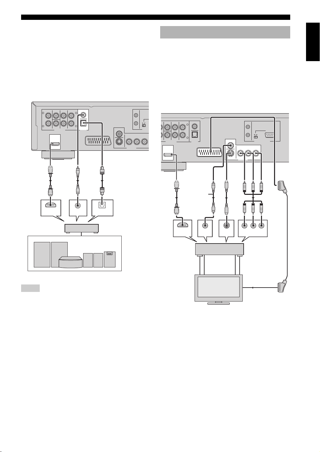
■ Digital connections
If you want to use the Dolby Digital, DTS or MPEG
function on your AV receiver, connect HDMI <A> or
DIGITAL (COAXIAL) <B> or DIGITAL (OPTICAL)
<C> jack of this unit to the corresponding input jacks of
your AV receiver using a commercially available HDMI,
digital coaxial or digital optical cable.
See “HDMI jack <A>” on page 12 about HDMI
connection.
This unit (U.K. and Europe models)
CENTER
L
R
SUBWOOFER
SURROUND
HDMI
HDMI
IN
FRONT
AUDIO OUT DIGITAL
COAXIAL
L
R
OPTICAL
MIXED 2CH
COAXIAL INOPTICAL
IN
ON OFF
OUT
VIDEO
AV
S VIDEO
R / CR PB / CB Y
P
COMPONENT
VIDEO OUT
REMOT
<C><B><A>
IN
Video connections
This unit has HDMI, composite video, S-video,
component video and SCART output jacks. If your AV
receiver has video output jacks, connect your receiver and
then your TV so that you can use one TV for several
different video sources (LD, VCR etc.) by simply
switching the input source selector on your receiver.
Use the one that corresponds to the input jacks on the
component to be connected.
This unit (U.K. and Europe models)
FRONT
L
R
MIXED 2CH
pin cable
(supplied)
COAXIAL
OPTICAL
Video
IN
RS-232C
ON OFF
OUT
VIDEO
AV
S VIDEO
P
R / CR PB / CB Y
COMPONENT
VIDEO OUT
REMOTE CONTROL
<C> <D> <E><B><A>
CENTER
SUBWOOFER
ND
AUDIO OUT DIGITAL
HDMI
English
AV receiver
Speakers
Notes
• If you make a connection with DIGITAL (COAXIAL) <B> or
DIGITAL (OPTICAL) <C>, set [Digital Out] to [All] (see
“Setting the digital output” on page 28).
• If the audio format of the digital output does not match the
capabilities of your receiver, the receiver produces a distorted
sound or no sound at all. Make sure to select the appropriate
audio format from the menu screen on the disc.
Pressing AUDIO on the remote control once or more may
change not only the audio languages but also the audio format.
• SA-CD audio signals are not output from DIGITAL
(COAXIAL/OPTICAL) jacks.
• If you want to enjoy Dolby Digital, DTS, and MPEG formats,
you must connect this unit to an AV receiver that supports
these formats.
HDMI
IN
AV
receiver
TV
HDMI
OUT
HDMI
IN
VIDEO
OUT
VIDEO
IN
S-VIDEO
IN
S VIDEO
S VIDEO
OUT
IN
VIDEO
IN
PR/CR YPB/CB
COMPONENT VIDEO IN
COMPONENT
VIDEO OUT
COMPONENT
VIDEO IN
11 En
CONNECTIONS
■ HDMI jack <A>
HDMI (High-Definition Multimedia Interface) provides
high quality digital audio and video on a single
connection. Connect HDMI jack of this unit to the HDMI
input jack of your AV receiver, and then to that of your TV
using a commercially available HDMI cable.
If your receiver does not have HDMI output jack, you can
achieve a better video image by connecting HDMI jack of
this unit directly to the HDMI input jack of your TV.
Notes
• To output HDMI signals, set the HDMI mode to “on” by
pressing HDMI button on the remote control.
• You can use an HDMI-DVI converter cable in order to connect
this unit to HDCP-compatible DVI-D components. In this case,
you need to use another audio connection in addition to this
connection because no audio signals are output.
■ Composite video jack <B>
Connect VIDEO OUT (VIDEO) jack of this unit to the
video input jack of your AV receiver, and then to that of
your TV using the supplied video pin cable.
■ S-video jack <C>
S-video connections achieve a clearer picture than
composite video connections by transmitting video signals
on separate wires for luminance (Y) and chrominance (C).
Connect VIDEO OUT (S VIDEO) jack of this unit to
S-video input jack of your AV receiver, and then to that of
your TV using a commercially available S-video cable.
■ SCART terminal <E>
(U.K. and Europe models only)
If your TV has only a terminal for video input, you can
connect the TV directly to this unit.
Connect AV terminal of this unit to SCART input terminal
of your TV using a commercially available SCART cable.
Note
• Ensure that the “TV” indication on SCART cable is connected
to the TV set and “DVD” indication on SCART cable is
connected to this unit.
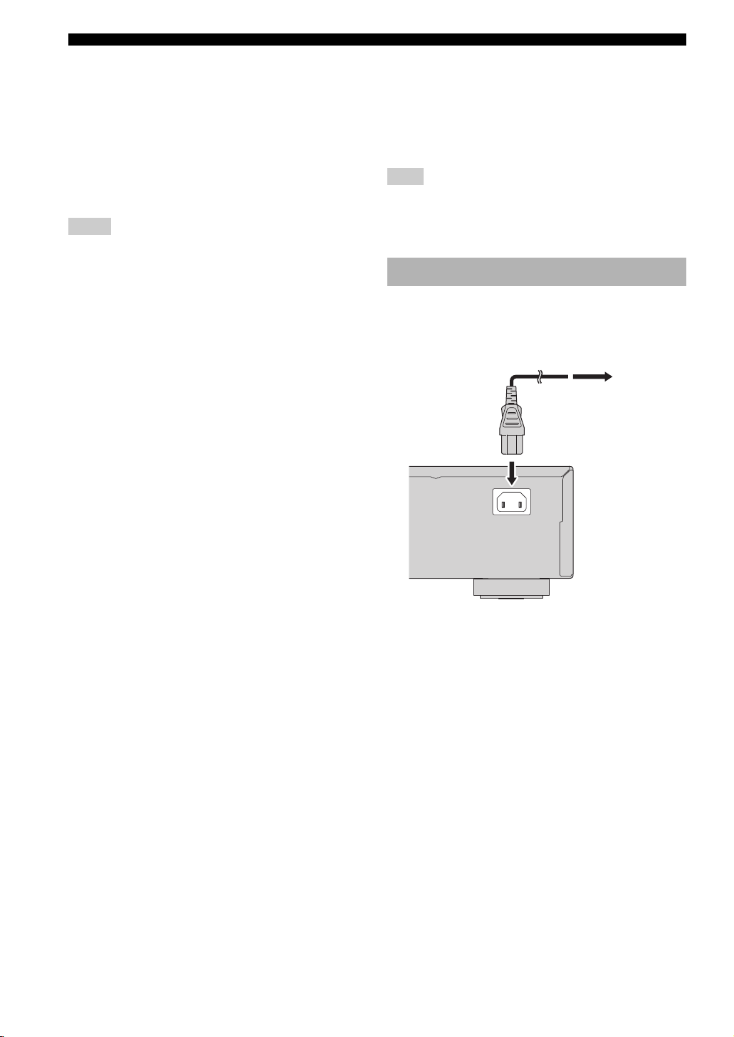
Connecting the power cable
After all other connections are complete, plug the supplied
power cable into MAINS of this unit and then plug the
power cable to an AC outlet.
To a n AC
outlet
MAINS
■ Component video jacks <D>
Component video connections achieve higher fidelity
color reproduction than S-video connections by
transmitting video signals on separate wires for luminance
(Y: green) and chrominance (P
VIDEO OUT (COMPONENT) jacks of this unit to the
component input jacks of your AV receiver, and then to
those of your TV using a commercially available
component cable. Observe the color of each jack when
you make connections.
If your receiver does not have component output jacks,
you can achieve a better video image by connecting the
component output jacks of this unit directly to the
component input jacks of your TV.
B: blue, PR: red). Connect
12 En
 Loading...