

Yamaha DVDS-2500 Service Manual
DVD-AUDIO/VIDEO SACD PLAYER
DVD-S2500
SERV ICE MA NUA L
SERV ICE MA NUA L
IMPORTANT NOTICE
This manual has been provided for the use of authorized YAMAHA Retailers and their service personnel.
It has been assumed that basic service procedures inherent to the industry, and more specifically YAMAHA Products, are already
known and understood by the users, and have therefore not been restated.
WARNING: Failure to follow appropriate service and safety procedures when servicing this product may result in personal
IMPORTANT: The presentation or sale of this manual to any individual or firm does not constitute authorization, certification or
The data provided is believed to be accurate and applicable to the unit(s) indicated on the cover. The research, engineering, and service
departments of YAMAHA are continually striving to improve YAMAHA products. Modifications are, therefore, inevitable and
specifications are subject to change without notice or obligation to retrofit. Should any discrepancy appear to exist, please contact the
distributor's Service Division.
WARNING: Static discharges can destroy expensive components. Discharge any static electricity your body may have
IMPORTANT: Turn the unit OFF during disassembly and part replacement. Recheck all work before you apply power to the unit.
injury, destruction of expensive components, and failure of the product to perform as specified. For these reasons,
we advise all YAMAHA product owners that any service required should be performed by an authorized YAMAHA
Retailer or the appointed service representative.
recognition of any applicable technical capabilities, or establish a principle-agent relationship of any form.
accumulated by grounding yourself to the ground buss in the unit (heavy gauge black wires connect to this buss).
■ CONTENTS
TO SERVICE PERSONNEL . . . . . . . . . . . . . . . . . .2–4
PREVENTION OF ELECTRO STATIC DISCHARGE . . . . . .
LOCALE MANAGEMENT INFORMATION . . . . . . . .5
FRONT PANEL . . . . . . . . . . . . . . . . . . . . . . . . . . . . . .5
REMOTE CONTROL PANEL . . . . . . . . . . . . . . . . . . .5
REAR PANELS . . . . . . . . . . . . . . . . . . . . . . . . . . . . . .6
SPECIFICATIONS /
REPAIR NOTES /
INTERNAL VIEW /
100940
参考仕様 . . . . . . . . . . . . . . . . . . 6–7
修理上の留意点 . . . . . . . . . . . . . . . .8
各部名称 . . . . . . . . . . . . . . . . . . . . . 8
DISASSEMBLY PROCEDURES /
4
分解手順 . . . . . . . . . . . . . . . . . . . . . . . . . . . . . . . . .9–10
BLOCK DIAGRAM . . . . . . . . . . . . . . . . . . . . . . . . . . .11
WIRING DIAGRAM . . . . . . . . . . . . . . . . . . . . . . . . . .12
PRINTED CIRCUIT BOARD . . . . . . . . . . . . . . . .13–21
SCHEMATIC DIAGRAM . . . . . . . . . . . . . . . . . . .22–49
EXPLODED VIEW . . . . . . . . . . . . . . . . . . . . . . . . . . .50
MECHANICAL PARTS . . . . . . . . . . . . . . . . . . . . . . .51
DVD-S2500
’05.01

DVD-S2500
■ TO SERVICE PERSONNEL
1. Critical Components Information
Components having special characteristics are marked Z
and must be replaced with parts having specifications equal
to those originally installed.
2. Leakage Current Measurement (For 120V Models Only)
When service has been completed, it is imperative to verify
that all exposed conductive surfaces are properly insulated
from supply circuits.
● Meter impedance should be equivalent to 1500 ohms shunted
by 0.15µF.
WALL
OUTLET
● Leakage current must not exceed 0.5mA.
● Be sure to test for leakage with the AC plug in both
polarities.
EQUIPMENT
UNDER TEST
INSULATING
TABLE
AC LEAKAGE
TESTER OR
EQUIVALENT
WARNING: CHEMICAL CONTENT NOTICE!
The solder used in the production of this product contains LEAD. In addition, other electrical/electronic and/or
plastic (where applicable) components may also contain traces of chemicals found by the California Health and
Welfare Agency (and possibly other entities) to cause cancer and/or birth defects or other reproductive harm.
DO NOT PLACE SOLDER, ELECTRICAL/ELECTRONIC OR PLASTIC COMPONENTS IN YOUR MOUTH FOR
ANY REASON WHATSOEVER!
Avoid prolonged, unprotected contact between solder and your skin! When soldering, do not inhale solder fumes
or expose eyes to solder/flux vapor!
If you come in contact with solder or components located inside the enclosure of this product, wash your hands
before handling food.
WARNING: Laser Safety
This product contains a laser beam component. This
component may emit invisible, as well as visible radiation,
which may cause eye damage. To protect your eyes
and skin from laser radiation, the following precautions
must be used during servicing of the unit.
1) When testing and/or repairing any component within
the product, keep your eyes and skin more than 30 cm
away from the laser pick-up unit at all times. Do not
stare at the laser beam at any time.
2) Do not attempt to readjust, disassemble or repair the
laser pick-up, unless noted elsewhere in this manual.
3) CAUTION : Use of controls, adjustments or
performance of procedures other than those specified
herein may result in hazardous radiation exposure.
Laser Emitting conditions:
1) When the Top Cover is removed, and the STANDBY/
ON SW is turned to the "ON" position, the laser
component will emit a beam for several seconds to
detect if a disc is present. During this time (5-10 sec.)
the laser may radiate through the lens of the laser pickup unit. Do not attempt any servicing during this period!
If no disc is detected, the laser will stop emitting the
beam. When a disc is loaded, you will not be exposed
to any laser emissions.
警告:レーザーの安全対策
本機はレーザー光線を放射する部品を搭載しています。こ
の部品が放射するレーザー光線は目に損傷を起こします。
このレーザー光線から目及び肌を保護するために、本機の
修理作業中は下記の注意を厳守してください。
1)テスト時または修理時、目及び肌を光ピックアップか
ら30cm以上離してください。いかなる場合もレーザー
光線を見つめないでください。
2)光ピックアップの再調整及び分解はしないでください。
3)このマニュアル上で指定されている以外の制御、調整、
手順はレーザー光線を照射される結果を招く恐れがあ
ります。
レーザー放射条件
1)トップカバーを取り外しSTANDBY/ONスイッチをON
にすると、ディスク検知のため5 〜10秒間、光ピック
アップからレーザー光線が放射されます。この間、修
理はしないでください。
ディスクが検知されなければ、レーザー光線の放射は
停止します。ディスクがセットされている場合、ディ
スクで遮られるのでレーザー光線は修理担当者に届き
ません。
2
DVD-S2500

DVD-S2500
2) The laser power level can be adjusted with the VR on
the pick-up PWB, however, this level has been set by
the factory prior to shipping from the factory. Do not
adjust this laser level control unless instruction is
provided elsewhere in this manual. Adjustment of this
2)レーザーパワーレベルは光ピックアップ基板上のVRに
より調整可能ですが、工場出荷前に調整セット済みな
ので、このVRは廻さないでください。このVRを廻す
と装置からのレーザー光線の放射レベルが上がる恐れ
があります。
control can increase the laser emission level from the
device.
Laser Diode Properties
Type: Semiconductor laser GaAlAs
Wave length: 650 nm (DVD/SA-CD)
790 nm (VCD/CD)
Output Power: 7 mW (DVD/SA-CD/VCD/CD)
レーザー
タイプ 半導体レーザーGaAlAs
波長 650nm(DVD/SA-CD)
790nm (VCD/CD)
出力 7mW(DVD/SA-CD/VCD/CD)
VARO! : AVATTAESSA JA SUOJALUKITUS OHITETTAESSA OLET ALTTIINA NÄKYMÄTTÖMÄLLE
LASER-SÄTEILYLLE. ÄLÄ KATSO SÄTEESEEN.
VARNING! : OSYNLIG LASERSTRÅLNING NÄR DENNA DEL ÄR ÖPPNAD OCH SPÄRREN ÄR URKOPPLAD.
BETRAKTA EJ STRÅLEN.
WARNING
The use of optical instruments with this product will increase eye hazard.
Repair handling should take place as much as possible with a disc loaded inside the player.
CAUTION
radiation when open. Avoid exposure to beam.
CAUTION VISIBLE AND INVISIBLE LASER RADIATION
WHEN OPEN. AVOID EXPOSURE TO BEAM
ADVARSEL SYNLIG OG USYNLIG LASERSTRÅLING VED
ÅBNING UNDGÅ UDSÆTTELSE FOR
STRÅLING
ADVARSEL SYNLIG OG USYNLIG LASERSTRÅLING NÅR
DEKSEL ÅPNES UNNGÅ EKSPONERING FOR
STRÅLEN
VARNING SYNLIG OCH OSYNLIG LASERSTRÅLNING
NÄR DENNA DEL ÄR ÖPPNAD BETRAKTA EJ
STRÅLEN
VARO! AVATT AESSA OLET ALTTIINA NÄKYVÄLLE JA
NÄKYMÄTTÖMÄLLE LASER SÄTEILYLLE. ÄLÄ
KATSO SÄTEESEEN
VORSICHT SICHTBARE UND UNSICHTBARE
LASERSTRAHLUNG WENN ABDECKUNG
GEÖFFNET NICHT DEM STRAHL
AUSSETSEN
DANGER VISIBLE AND INVISIBLE LASER RADIATI ON
WHEN OPEN. AVOID DIRECT EXPOSURE TO
BEAM
ATTENTION RAYONNEMENT LASER VISIBLE ET INVIS-
IBLE EN CAS D'OUVERTURE EXPOSITION
DANGEREUSE AU FAISCEAU
- Visible and invisib
le laser
DVD-S2500
DPX-1200
3

DVD-S2500
J model
Warning for power supply
The primary side of the power supply carries live mains voltage when the pla y er is connected to the mains e ven when
the player is switched off !
This primary area is not shielded so it is possible to touch copper tracks and/or components when servicing the player.
Service personnel have to take precautions to prevent touching this area or components in this area .
Note:
The screws on the DVD mechanism may never be touched, removed or re-adjusted.
Handle the DVD mechanism with care when the unit has to be exchanged!
The DVD mechanism is very sensitive for dropping or giving shocks.
■ PREVENTION OF ELECTRO STATIC DISCHARGE
The laser diode in the D VD mechanism ma y be damaged due to static electricity from clothes or the human body. Use caution
to prevent electro static damage when servicing or handling the DVD-mechanism.
1. Grounding for electro static damage prevention
Some devices, such as the DVD player, use an optical pickup (laser diode) that will be damaged by static electricity in the
working environment. Only attempt service after ensuring that all grounding procedures have been completed.
1. W orktable grounding
Put a grounded conductive material (sheet) or iron sheet on the area where the optical pickup is placed.
2. Human body grounding
Use an anti-static wrist strap to discharge the static electricity from your body.
Anti-static wrist strap
1MΩ
Conductive material
(sheet) or steel sheet
2. Handling Precautions for DVD mechanism
1. Handle the DVD mechanism gently, as it is an extremely high-precision assembly.
2. The flexible cable lines may break if an excessive force is applied to it. Use caution when handling the cable.
3. The semi-fixed resistor for laser power adjustment should not be adjusted. Do not turn the resistor.
4
DVD-S2500

DVD-S2500
■ LOCALE MANAGEMENT INFORMATION
Locale Management Information : This DVD player is designed and manufactured to respond to the Locale
Management Information that is recorded on a DVD disc. If the Locale number described on the DVD disc does not
correspond to the Locale number of this DVD player, this DVD player cannot play this disc.
This product incorporates copyright
protection technology that is protected by
method claims of certain U.S. patents and
other intellectual property rights owned by
Macrovision Corporation and other rights
owners. Use of this copyright protection
technology must be authorized by
Macrovision Corporation, and is intended
for home and other limited viewing uses
only unless otherwise authorized by
Macrovision Corporation. Reverse
engineering or disassembly is prohibited.
■ FRONT PANEL
t
w
q
r
w
t
t
y
e
w
r
■ REMOTE CONTROL PANEL
DVD-S2500
DPX-1200
5
DVD-S2500
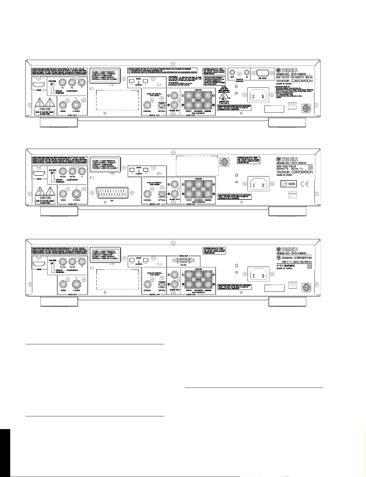
■ REAR PANELS
▼ U model
▼ G model
▼ J model
■ SPECIFICATIONS/参考仕様
PLAYBACK SYSTEM /対応ディスク
DVD-Audio
DVD-Video
Super Audio-CD, Stereo/Multi-channel and Hybrid disc
DVD+R, DVD+RW
DVD-R, DVD-RW (Video Format)
Video CD (VCD)
Super Video CD (SVCD)
CD-Audio (CD-DA)
CD-R/CD-RW (CD-DA, VCD, SVCD)
MP3, JPEG
VIDEO PERFORMANCE /ビデオ部
Video Output / 映像出力信号
1 Vpp into 75 ohms
S-Video Output / Sビデオ信号出力
Y: 1Vpp into 75 ohms
C: 0.3Vpp into 75 ohms (PAL)
C: 0.286Vpp into 75 ohms (NTSC)
Component Video Output / コンポーネントビデオ出力
Y: 1Vpp into 75 ohms
RGB (SCART) Output
D1/D2 Output D1: 1Vpp into 75 ohms (J model)
Pb/Cb Pr/Cr: 0.7Vpp into 75 ohms
0.7 Vpp into 75 ohms (G model)
D2:
0.7Vpp into 75 ohms (J model)
AUDIO FORMAT /オーディオフォーマット
DSD Multi-channel and Stereo
Dolby Digital/DTS/MPEG Compressed Digital
PCM/Packed PCM fs.48, 96, 192, and 44.1, 88.2
MP3 (ISO9660) 32, 44.1, 48, and 16, 22.05, 24 kHz
Full decoding of Dolby Digital, DTS and MPEG multi-channel sound/
analogue stereo sound
Dolby Surround-compatible downmix from Dolby Digital multi-channel sound
3D Sound for virtual 5.1 channel sound on two speakers
Dolby Pro Logic II 5.1 ch decoding from the stereo source
176.4 kHz 16, 20, 24 bits
6
DVD-S2500

DVD-S2500
ドルビーラボラトリーズからの実施権
。
1
-
AUDIO PERFORMANCE /オーディオ特性
DA Converter / DAコンバーター 24 bits
Signal-Noise Ratio / SN比 115 dB
Dynamic Range / ダイナミックレンジ
(DVD 48 kHz 24 bit) 103 dB
(Super Audio CD) 107 dB
DVD fs 96 kHz 2 Hz – 44 kHz
CD/VCD fs 44.1 kHz 2 Hz – 20 kHz
Distortion and Noise / 全高調波歪率 (1 kHz)
0.0017% (DVD 48 kHz 24 bit)
TV STANDARD (PAL/50Hz) (NTSC/60Hz)
Number of lines 625 525
Playback Multistandard (PAL/NTSC)
CONNECTIONS /接続端子
Y Output Cinch (green)
Pb/Cb Output Cinch (blue)
Pr/Cr Output Cinch (red)
SCART Euroconnector (G model)
D Terminal (J model)
S-Video Output Mini DIN, 4 pins
Video Output Cinch (yellow)
Audio Output (L+R) Cinch (white/red)
Digital Output 1 coaxial, 1 optical
HDMI Output Type A
IEEE1394 Output 4 pins x 2
6 channel Analog Output
• Audio Main L/R Cinch (white/red)
• Audio Surround L/R Cinch (white/red)
• Audio Center Cinch (blue)
• Audio Subwoofer Cinch (black)
GENERAL /一般
Dimensions (W x H x D) / 寸法(幅x高さx奥行き)
Weight / 質量 Approx. 5.6 Kg (12 lbs 5 oz)
Finish / 仕上げ Gold Color
Power Supply / 電源電圧 AC120V, 60Hz (U model)
Power Consumption / 消費電力 33W
Standby Power Consumption (reference data) /
待機時消費電力(参考値) 1W
435 x 100 x 314 mm
(17-1/8" x 3-15/16" x 12-3/8")
Black Color
Titanium Color
AC230-240V, 50Hz (G model)
AC100V, 50/60Hz (J model)
(G, J models)
(U, G models)
(G model)
ACCESSORIES /付属品
Remote Control, Batteries x 2, Power Cable x 1
* Specifications subject to change without prior notice.
U ......... USA model
G ......... European model
Audio/Video Cable (U, J models) x 1
Audio Pin Cable (G model) x 1
Video Cable (G model) x 1
J ......... Japanese model
Manufactured under license from
Dolby Laboratories.
“Dolby”, “Pro Logic”, and the
double-D symbol are trademarks of
Dolby Laboratories.
“DTS” and “DTS Digital Surround”
are registered trademarks of Digital
Theater Systems, Inc.
“DCDi” is a trademark of Faroudja, a
division of Genesis Microchip, Inc.
HDMI, the HDMI logo and HighDefinition Multimedia Interface are
trademarks or registered trademark of
HDMI Licensing LLC.
This product incorporates copyright protection
technology that is protected by method claims of certain
U.S. patents and other intellectual property rights owned
by Macrovision Corporation and other rights owners.
Use of this copyright protection technology must be
authorized by Macrovision Corporation, and is intended
for home and other limited viewing uses only unless
otherwise authorized by Macrovision Corporation.
Reverse engineering or disassembly is prohibited.
“i.LINK” and the “i.LINK” logo are trademarks of
Sony Corporation.
This product complies with the following i.LINK
interface specifications:
1. IEEE Std 1394a-2000, Standard for a High
Performance Serial Bus
2. Audio and Music Data Transmission Protocol 2.1
Following the standard for AM824 sequence adaptation
layers, the product is compatible with IEC60958
bitstream, DVD-A and SA-CD media.
に基づき製造されています。「ドル
ビー」、「PRO LOGIC」およびダブル
D記号は、ドルビーラボラトリーズの
商標です。
DTS およびDTS Digital Surround は
デジタルシアターシステムズの登録商
標です。
DCDi は、Genesis Microchip Inc. の
事業部門であるFaroudjaの商標です。
HDMIはHDMI Licensing, LLC の登
録商標です。
本製品は、著作権保護技術を採用しており、マクロビ
ジョン社及びその他の著作権利者が保有する米国特許及
びその他の知的財産権によって保護されています。
この著作権保護技術の使用は、マクロビジョン社の許可
が必要で、またマクロビジョン社の特別な許可がない限
り家庭用及びその他の一部の視聴用の使用に制限されて
います。分解したり、改造することも禁じられています
i.LINK とi.LINK ロゴ はソニー株式会社の商標です。
この機器のi.LINK インターフェースは、以下の規格に基
づいて設計されています。
1. IEEE Std 1394a-2000, Standard for a High
Performance Serial Bus
Audio and Music Data Transmission Protocol 2.
2.
この規格のAM824 sequence adaptation layers の
中の、IEC60958 bitstream、DVD-Audio またはSA
CD に対応しています。
DVD-S2500
DPX-1200
7

DVD-S2500
■ REPAIR NOTES / 修理上の留意点
1) Power Supply Unit
The power supply unit has to be replaced in case of
failure.
2) DVD Mechanism
The DVD mechanism is a non-repair able unit and in case
of failure, it has to be replaced with a complete DVD
machanism.
3) P.C.B. Ass’y
When the P.C.B. Ass’y is found faulty , replace each P.C.B.
■ INTERNAL VIEW / 各部名称
wq e r
t y
1)電源ユニット
故障の場合は、電源ユニットを交換してください。
2)DVDメカ
DVDメカは、修理不可能なユニットなので、故障の場
合は、DVDメカ全体を交換してください。
3)PCBAssy
故障の場合は、各PCBを交換してください。
u i
q POWER SUPPLY UNIT
w RS232C Board (U model only)
e AV Board
r HDMI D2 Board (J model only)
t IEEE1394 Board
y PSCAN Board
u DVD MECHANISM Unit
i MONO Board
o FRONT (2) Board
!0 FRONT (1) Board
8
DVD-S2500
!0o

■ DISASSEMBLY PROCEDURES
DVD-S2500
See EXPLODED VIEW for item numbers.
Front Panel [101]
Open Tray (see HOW TO MANUALLY EJECT THE TRAY).
➔
Unlock Tray lid and close tray.
➔
Remove 7 screws [283] (Front Panel to Frame. 4 on Frame and 3
➔
on bottom).
➔
Unlock Front panel by releasing successively 4 snaps (2 on the
top and 2 on the bottom).
Sub Panel Ass'y [103]
Remove cable connections. [1404]
➔
Unlock Sub panel ass'y by releasing successively 4 snaps (2 on
➔
the side and 2 on the bottom).
Front (1) Display board [1001(1)]
➔
Remove 4 screws [282] (Board to
Front panel).
➔
Dismount board.
Front (2) Key Matrix board [1001(2)]
➔
Remove 4 screws [282] (Board to Front
panel).
Dismount board.
➔
IEEE1394 board [1007]
Remove 3 cable connections. [1100] [1300] [1401]
➔
Remove 2 screws [283] (Board to rear panel).
➔
Remove 1 screw [283] (DVD Mechanism).
➔
Dismount board.
➔
DVD Mechanism
Remove 2 cable connections.
➔
[1700] [1702]
Open tray.
➔
(see HOW TO MANUALLY EJECT
THE TRAY)
Unlock Tray lid and close tray.
➔
Remove 4 screws [283]
➔
(DVD Mechanism to frame).
Lift DVD Mechanism up slightly and
➔
move it backward to remove.
Top Cover [240]
Remove 7 screws [281]
➔
(4 on side and 3 on rear side)
Lift cover from rearside to remove.
➔
AV board [1002]
Remove 4 cable connections.
➔
[1400] [1500] [1601] [1404]
Remove 7 (U) or 9 (G) screws [282]
➔
(Board to rear panel).
Release 2 spacers locking (Board to frame).
➔
➔
Dismount board.
When disassembling, use the special screw driver with tip shape in figure.
Mounting
Dismounting
PSCAN board [1005]
➔
Remove 2 cable connections. [1000] [1402]
Remove 1 screw [282] and 1 screw [283]
➔
(Board to rear panel).
Remove 1 screw [283] (Board to frame).
➔
➔
Dismount board.
MONO board
Remove 5 cable connections.
➔
[1400] [1500] [1700] [1702] [1900]
➔
Remove 4 screws [283] (Board to frame).
Dismount board.
➔
T10
2.7 mm
RS232C board [1008] (U model only)
➔
Remove cable connections. [1402]
Remove 1 screw [282] and 2 jack screws
➔
(Board to rear panel).
Dismount board.
➔
Power Supply Unit [1004]
Remove 2 cable connections. [CON1] [CN1]
➔
➔
Remove 2 screws [283] (Board to frame).
Release 2 spacers locking. (Board to frame).
➔
Dismount board.
➔
● HOW TO MANUALLY EJECT THE TRAY
a. Turn the player bottom up.
b. Move the slider in the direction indicated
with a screw driver until the tray is ejected.
c. Gently pull the tray out.
Tray
c
b
Frame
Rear
Slider
a
Slider
Screw Driver
Front
9

DVD-S2500
ー
■ 分解手順
項目番号については分解図を参照してください。
Front Panel [101]
➔
トレーを開きます 。
(「手動でトレーを開く方法」を参照)
トレーリッドを外し、トレーを閉めます。
➔
フロントパネルを取り付けているネジ[283]7本(上
➔
面4本、底面3本)を外します。
4ヶのスナ ッ プ(上面の2ヶ、底面の2ヶ)を外して、フ
➔
ロン トパネルを取り外します。
Sub Panel Ass'y [103]
➔
ケーブルの 接続を外します。[1404]
4ヶのスナ ッ プ(側面の2ヶ、底面の2ヶ)を外して、サ
➔
ブパネルAss'yを取り外します。
Front (1) Display board [1001(1)]
➔
ボー ドをフロントパネルに取り付けてい
るネジ[282]4本を外します。
➔
ボー ドを取り外します 。
Front (2) Key Matrix board [1001(2)]
➔
ボードをフロン トパネルに取り付けている
ネジ[282]4本を外します。
ボー ドを取り外します 。
➔
IEEE1394 board [1007]
➔
ケーブルの接続3本を外します。
[1100][1300][1401]
ボード を リアパネルに取り付けてい
➔
るネジ[283]2本を外します。
ボードをDVDメカに取り付けている
➔
ネジ[283]1本を外します。
➔
ボー ドを取り外します 。
DVD Mechanism
➔
ケーブルの接続2本を外します。[1700][1702]
➔
トレーを開きます
(「手動でトレーを開く方法」を参照)
➔
トレーリッドを外し、トレーを閉めます 。
DVDメカをフレームに取り付けているネジ[283]
4本を外します。
DVDメカを少し持ち上げて後方に動かして取り
外します。
Top Cover [240]
➔
ネジ[281]7本(側面の4本、リア面の
3本)を外します。
カバー を後ろ側か ら上げて取り外 し ま
➔
す。
HDMI D2 board [1006]
➔
ケーブルの 接続を外します。[1101]
➔
ボード を リアパネルに取り付けてい
るネジ[282]2本を外します。
➔
ボー ドを取り外します 。
➔
ケーブルの接続4本を外します。
[1400][1500][1601][1404]
➔
ボー ドをリアパネルに取り付けているネジ[282]
7本を外します。
ボード を フレームに取り付けているスペーサー
➔
2ヶ を ゆるめます。
➔
ボー ドを取り外します 。
取り付け
取り外し
AV board [1002]
PSCAN board [1005]
➔
ケーブルの接続3本を外します。
[1000][1302][1402]
ボード を リアパネルに取り付けてい
➔
るネジ[282]1本、[283]1本を外し
ます。
➔
ボード を フ レームに取り付けている
ネジ[283]1本を外します。
➔
ボー ドを取り外します 。
MONO board
➔
ケーブルの接続5本を外します。
[1400][1500][1700][1702][1900]
➔
ボード を フレームに取り付けているネジ
[283]4本を外します。
➔
ボー ドを取り外します 。
分解には図のような特殊ドライバーを使用します。
T10
2.7 mm
Power Supply Unit [1004]
➔
ケーブルの接続2本を外します。[CON1][CN1]
➔
ボー ドをフレームに取り付けているネジ[283]2本
を外します。
➔
ボード を フ レームに取り付けているスペーサー
2ヶ を ゆるめます。
➔
ボー ドを取り外します 。
10
●手動でトレーを開く方法
a. 本体を上下反転します。
b.トレーが出てくるまで、ドライバーでスライダーを
図に示す矢印の方向に動かします。
c. トレーをそっと引き出します。
トレー
c
a
b
フレーム
リア
スライダ
スライダー
ドライバー
フロント

■ BLOCK DIAGRAM
S400
(AUDIO)
IEEE1394
BOARD
DD(2)
DD(13)
INTEGRATED
DD(1)
DD(14)
DD(0)
DD(15)
8108
7200
LLC/PHY
GND
NO_KEY
DMAREQ
40P
GND
DIOWn
1100
1
2
3
4
5
6
7
8
9
1300
5V
GND
3V3
12V
CS5
RW
ALE
GND
MEDUSA_INT
ATARSTn
123456789
GND
7400
EEPROM
DD(7)
DD(8)
DD(6)
DD(9)
DD(5)
DD(10)
DD(4)
DD(11)
DD(3)
DD(12)
10111213141516171819202122232425262728293031323334353637383940
DVD-S2500
IC1
REMOTE
CONTROL
IN
OUT
JK1 JK2
IC5
RS-232C
CB2
IC3
M30626FHPFP
RS232C BOARD
(U model only)
FDout
7512
Buffer
7517 /
7508
0/6/12
Video_SEL
1 SCL_5V
2 SDA_5V
3 SCART1
4 SCART0
SCART
( G model only)
RED
GREEN
0/6/12
7511
Buffer
5 VGND
6 BLUE_U
7 VGND
8 GREEN_Y
9 VGND
10 RED_V
11 VGND
12 Y_Mono
30P FLEX
8104 (80 mm)
0/6/12
13 VGND
14 C_Mono
BLUE
7507
Buffer
15 VGND
16 NC
SCART_L
17 + 3V3
18 +3V3
1501
19 +5V
1
SCART_R
20 +12V
21 +12V
7514
Buffer
22 MUTE
Y_MONO
23 GND
24 NC
S-VIDEO
7515
Buffer
25 PCM_LTRT
26 NC
27 NC
28 NC
OUT
Y
C_MONO
29 GND
30 DIG_OUT
1500
1503
C
7501
Op Amp
TV_LScart
TV_R_Scart
AV BOARD
MIXED 2ch
L/R Out
Stereo_R_OUT
Stereo_L_OUT
1 +3V3
2 +3V3
3 +5V
4 GND
5 GND
6 GND
1300
7 +12V
1601
Mute
Multi Channel Audio Out
3 GND
CENTER
4 SEL3
5 GND
7402
Op Amp
7200
CS4382
6 SDT3
7 GND
8 SEL2
1301-1
SUB-WOOFER
Op Amp
DAC
9 GND
10 SDT2
11 GND
12 SEL1
13 GND
30P FLEX
8103 (80 mm)
1401 1401
1
GND
2
MCLK_iCEM
3
GND
4
DSD_PCM(3)
5
GND
6
DSD_PCM(2)
7
GND
DSD_PCM(4)
DSD_PCM(1)
DSD_PCM(0)
DSD_PCM(7)
DSD_PCM(6)
MCLK_iCEM
+5VSTBY
PCM_LTRT
SPDIF
MCIF_INT2
8
9
GND
10
11
GND
12
13
GND
14
15
GND
16
17
GND
18
19
GND
20
21
GND
22
SCL
23
SDA
24
GND
25
26
GND
27
28
29
30
DSD_PCM(15)
DSD_PCM(10)
GND
DIORn
GND
IORDY
CSEL
DMACK
GND
INTRQ
IOCS16
DA(1)
PDIAG
DA(0)
DA(2)
IDE_CS0n_A
IDE_CS1n_A
DASP
GND
1
2
3
4
5
6
7
8
9
10
11
12
13
14
15
16
17
18
19
30P FLEX
8110 (80 mm)
20
21
22
23
24
25
26
27
28
29
30
GND
MCLK_iCEM
GND
DSD_PCM(3)
GND
DSD_PCM(2)
GND
DSD_PCM(15)
GND
DSD_PCM(4)
GND
DSD_PCM(1)
GND
DSD_PCM(0)
GND
DSD_PCM(7)
GND
DSD_PCM(6)
GND
MCLK_iCEM
GND
SCL
SDA
GND
DSD_PCM(10)
GND
+5VSTBY
PCM_LTRT
SPDIF
MCIF_INT2
SURR_L
7402
Op Amp
7320
CS4398
AUDIO DAC
1 GND
SURR_R
2 GND
FRONT_L
7302
14 SDT1
15 GND
16 LRCLK
TVL
TVR
17 GND
1140-A
FRONT_R
7301
Op Amp
18 BCLK
19 GND
20 MB_CLK
Video Out
CVBS
7513
Buffer
CVBS_Scart
Y_mix
C_mix
TV_L
TV_R
SCL_3V3
Level
Shifter
SCA_3V3
21 GND
22 SCL_5V
23 SDA_5V
24 GND
25 DSD(Lt)
26 GND
27 DSD(Rt)
21
2019 1817 1615 1413 1211 10 9 8 7 6 5 4 3 2
CVBS
7510
Buffer
7525
Op Amp
7605
PCF8574T
28 GPIO 2
29 GPIO 3
30 GPIO1
1400
CVBS
COAXIAL
OUT
5503
+5VA
+8VA
+3V3D
+3V3_DAC
+3V3_OSC
-8VA
7604
L7908
+12V
+3V3
DGN
+3V3
DGND-+5V
1234567
1504
7603
L7805
7602
L7808
7600
LD1117
1103
OPTICAL
OUT
DRIVER
+3V3_Power 1
+3V3_Power 2
+12V_Power 4
+12VSTBY 5
+5VSTBY 7
-12V_Power 9
-32V_Power 11
STBY_CTRL 12
7504
IR_SW
RC6_IN
UP_RESET
+5V_STBY
SCL_5V
SDA_5V
GND
STDBY_CTRL
1600
GND 3
GND 6
GND 8
GND 10
1402
1
2
3
4
5
6
7
8
IR_SW 1
uP Reset 2
RC6_IN 3
-24V 4
+12V 5
+5V stb 6
Stdby Ctrl 7
SCA 8
GND 9
SCL 10
CB1
1403
1
IR_232CSW
2
RC6
3
RESET
4
+5_STBY
5
SCK
6
SDA
7
GND
8
STBY_CTRL
123456789
1603
DD(7)
DD(8)
DD(6)
DD(9)
DD(5)
GNDB
ATARSTn
DD(10)
1602
1
2
3
4
5
6
7
8
9
5VP
GNDB
3V3P
12VP
HB_CS5nA
RW_A
ALE_A
GNDB
MEDUSA_INTn
SD5.2(S)
MONO BOARD
1700
10111213141516171819202122232425262728293031323334353637383940
DD(4)
DD(3)
DD(11)
DD(12)
DD(2)
DD(13)
DD(1)
DD(14)
33 MHZ
DD(0)
1800
GNDB
DD(15)
-
-
GNDB
GNDB
DIORn
DIOWn
MSM514265E
GNDB
-
IORDYn
7800
RAM
-
5VB
DA(1)-DA(0)
DA(2)
GNDB
INTRQ
7801
ALI
FE
SAE
7702
SP3721A
Signal Processor
& Laser Supply
M5705
Servo Controller
TE
RFOUT
MOTOR
7701
BA5954FP
Actuator Drivers
MOCTL
7707
LM833D
Disc Driver
SLEG
SFOCUS
STRACK
-
GNDB
IDE_CS0n_A
IDE_CS1n_A
M29F002BT
7709-7712
BC807/BC817
Tray Driver
7807
ROM
OPEN/CLOSE
1701
7404
74LVC1G125
7401
SDRAM
MT48LV4M162TG
LSI
7302
SDRAM
MT48LC16A2TG
GND 1
GND 3
GND 5
GND 7
GND 9
DSD5(Rs) 8
DSD_PCM3 4
DSD_PCM2 6
FURORE2
GND 11
DSD1(Rf) 12
DSD_PDM4 10
7400
DA_XCK 2
7101
ZIVA-5+
Mpeg Decoder
7301
SDRAM
MT48LC16A2TG
GND 13
DSD_PCM0 14
GND 15
GND 17
DSD_PCM7 16
DSD_PCM6 18
FLASH MEMORY
GND 19
GND 21
MB_CLK 20
7406
7407
I2C_CL_3V3
7201
M29W160DT
GND 24
I2C_CL 22
I2C_DA 23
I2C_DA_3V3
GND 26
DSD(Lt) 25
DSD(Rt) 27
5VB
7206
NVRAM
M24C64-WMN6
S_I2C_CL
S_I2C_DA
3V3B
GPIO2 28
GPIO3 29
GPIO1 30
1400
1 GND
2 I2C_DA
I2C_CL 1
I2C_DA 2
7507
7508
3 I2C_CL
4 GND
5 27M_CLK
VGND 5
VGND 7
SCART1 3
SCART0 4
B_VID(U) 6
Video Filters
VIDEO_ZIVA
6 GND
7 VDATA(0)
B GND
9 VDATA(1)
VGND 9
VGND 11
G_VID(Y) 8
R_VID(U) 10
7500 - 7506
10 GND
11 VDATA(2)
12 GND
13 VDATA(3)
14 GND
Y_VID 1 2
VGND 13
VGND 15
C_VID 14
15 VDATA(4)
16 GND
17 VDATA(5)
+3V3 17
+3V3 18
CVBS_VID 16
MUTE
18 GND
19 VDATA(6)
20 GND
+5V 19
+12V 20
+12V 21
74VC1G125
21 VDATA(7)
22 GND
23 DA_XCK
24 GND
NC 23
MUTE 22
PCM_BCK 24
7502
25 DA_BCK
26 GND
27 SPDIF
NC 27
NC 28
GND 26
PCM_Data 25
SPDIF
28 GND
29 DA_LRCK
30 HCS(3)
GND 29
SPDIF 30
3V3 1
3V3 2
5V 3
GND 4
GND 5
GND 6
12V 7
1501
1500
1900
FRONT (1) DISPLAY
BOARD
FTD DISPLAY
7100
TMP87CH74
KEY MATRIX
1
2
1102
FIL1
FIL2
7104
IR
1101
IR_SW 1
uP Reset 2
RC6_IN 3
-24V 4
+12V 5
+5V stb 6
Stdby Ctrl 7
SCA 8
GND 9
SCL 10
Filament
-24V
VKK
DRIVER
+12V
RESET
7102
+5Vstb
24P FLEX
DVD Mechanism
Actima A97SL
HDMI D2 BOARD
(J model only)
D1/D2
GND 13
PLUGDETN 12
LINE_3 11
LINE_2 10
LINE_1 9
+5VA 8
GND 7
V 6
GND 5
U 4
GND 3
Y 2
GND 1
1102
1101
1302
1 GND
2 DPDET#
3 DLINE 3
4 DLINE 2
5 DLINE 1
6 +5VA
7 GND
8 V
9 GND
10 U
13P FLEX
11 GND
8101 (220 mm)
12 Y
13 GND
YPbPr
30P FLEX
8102 (180 mm)
GND 2 5
GND 2 3
GND 3 0
SDA_5V 29
7201
PCF8574T
7202
ADV7310
P-SCAN/HDTV Encoder
7101
SDRAM
GND 2 1
GND 2 7
SCL_5V 28
YB (0) 24
27M_CLK 26
YB (1) 22
YB (2) 20
GND 1 9
PSCAN BOARD
GND 1 7
YB (4) 16
YB (3) 18
GND 1 5
GND 1 3
YB (5) 14
7100
FLI2310
GND 1 1
YB (7) 10
YB (6) 12
GND 7
GND 9
PCM_BCLK 6
PCM_MCLK 8
GND 5
SPCIF_IN 4
1003 1002
1000
GND 3
GPIO 1
PCM_LRCLK 2
7405
HDMI
TRANSMITTER
HDMI
1234567
+12V
+3V3
+3V3
DGND
DGND
1402
+5V
1204
1
2
CN1
GND 3
GND 6
GND 8
GND 10
+5VSTBY 7
+12VSTBY 5
+3V3_Power 1
+3V3_Power 2
12V_Power 9
+12V_Power 4
-24V_Power 11
STBY_CTRL 12
POWER SUPPLY
Standby
FRONT (2)
STANDBY
UNIT
CON1
BOARD
11

DVD-S2500
■ WIRING DIAGRAM
U model only
RS232
Board
CB1
8P
1402 1102
1404
1600
IEEE1394
1100
Board
1300
1401
30P
1401
1400
8103
30P
8110
AV Board
1500
8104
30P
1601
7P
1103
7P
8102
30P
1402 1000
PSCAN
Board
POWER
SUPPLY
UNIT
FRONT (2)
Board
CN1
CON1
12P
1201
DVD
MECHANISM
UNIT
2P
9P
24P
9P
10P
FRONT (1) Board
1400 1500 1900
1701
MONO Board
1700
8109
1602
SD5.2
40P
8108
1603
1302
8101
13P
1501
1101
HDMI D2
Board
J model only
1101
12

■ PRINTED CIRCUIT BOARD
FOR INFORMATION ONLY (NO REPLACEMENT PARTS WILL BE AVAILABLE)
DVD-S2500
The first digit of a component indicates the component type.
1xxx : Connector 3xxx : Resistor 5xxx : Coil 7xxx : IC, Transistor, FET
2xxx : Capacitor 4xxx : SMD jumper 6xxx : Diode 9xxx : Wire jumper
S400
(AUDIO)
IEEE1394 Board Top View
AV BOARD 1401
MONO BOARD 1602
MONO BOARD 1603
AV BOARD 1402
RS232C Board Top View
(U model only)
REMOTE
CONTROL
INOUT
RS-232C
IEEE1394 Board Bottom View
RS232C Board Bottom View
(U model only)
51
50
31
80
81
130
100
8
9
7
8
1
16
1
14
13

DVD-S2500
■ PRINTED CIRCUIT BOARD
FOR INFORMATION ONLY (NO REPLACEMENT PARTS WILL BE AVAILABLE)
MONO Board Top View
The first digit of a component indicates the component type.
1xxx : Connector 3xxx : Resistor 5xxx : Coil 7xxx : IC, Transistor, FET
2xxx : Capacitor 4xxx : SMD jumper 6xxx : Diode 9xxx : Wire jumper
DVD MECHANISM UNIT DVD MECHANISM UNIT
IEEE1394 BOARD 1100
IEEE1394 BOARD 1300
AV BOARD 1400AV BOARD 1500AV BOARD 1601
14
PSCAN BOARD 1000

■ PRINTED CIRCUIT BOARD
FOR INFORMATION ONLY (NO REPLACEMENT PARTS WILL BE AVAILABLE)
MONO Board Bottom View
DVD-S2500
The first digit of a component indicates the component type.
1xxx : Connector 3xxx : Resistor 5xxx : Coil 7xxx : IC, Transistor, FET
2xxx : Capacitor 4xxx : SMD jumper 6xxx : Diode 9xxx : Wire jumper
15

DVD-S2500
■ PRINTED CIRCUIT BOARD
FOR INFORMATION ONLY (NO REPLACEMENT PARTS WILL BE AVAILABLE)
AV Board Top View
The first digit of a component indicates the component type.
1xxx : Connector 3xxx : Resistor 5xxx : Coil 7xxx : IC, Transistor, FET
2xxx : Capacitor 4xxx : SMD jumper 6xxx : Diode 9xxx : Wire jumper
MONO BOARD 1900
PSCAN BOARD 1402
MONO BOARD 1500
MONO BOARD 1400 IEEE1394 BOARD 1401
POWER SUPPLY UNIT CN1
FRONT (1) BOARD 1101
RS232C BOARD CB1
16
VIDEO SVIDEO
VIDEO OUT
AV (SCART)
G model only
COAXIAL OPTICAL MIXED 2CH 6CH DISCRETE
(FRONT L/R, CENTER, SURROUND L/R, SUB WOOFER)
DIGITAL OUT AUDIO OUT
 Loading...