

Q
DVD AUDIO/VIDEO SACD PLAYER
Q
3
7
6
3
1
5
1
5
0
8
9
2
4
9
8
2
9
9
DVD-S2300MK2
SERVICE MANUAL
TEL 13942296513 QQ 376315150 892498299
IMPORTANT NOTICE
This manual has been provided for the use of authorized YAMAHA Retailers and their service personnel.
It has been assumed that basic service procedures inherent to the industry, and more specifically YAMAHA Products, are already
known and understood by the users, and have therefore not been restated.
WARNING: Failure to follow appropriate service and safety procedures when servicing this product may result in personal
IMPORTANT: The presentation or sale of this manual to any individual or firm does not constitute authorization, certification or
The data provided is believed to be accurate and applicable to the unit(s) indicated on the cover. The research, engineering, and
service departments of YAMAHA are continually striving to improve YAMAHA products. Modifications are, therefore, inevitable
TEL
13942296513
■ CONTENTS
TO SERVICE PERSONNEL .......................................... 2
PREVENTION OF ELECTRO STATIC DISCHARGE ... 4
LOCALE MANAGEMENT INFORMATION ................... 4
FRONT PANEL .............................................................. 5
REMOTE CONTROL PANEL ........................................ 5
REAR PANEL ................................................................ 6
SPECIFICATIONS.......................................................... 6
INTERNAL VIEW ........................................................... 7
DISASSEMBLY PROCEDURES ............................. 8~12
OPTICAL PICKUP SELF-DIAGNOSIS AND
REPLACEMENT PROCEDURE .................................. 13
SERVICE MODE AND SELF-DIAGNOSIS FUNCTION ...
and specifications are subject to change without notice or obligation to retrofit. Should any discrepancy appear to exist, please
contact the distributor's Service Division.
WARNING: Static discharges can destroy expensive components. Discharge any static electricity your body may have
IMPORTANT: Turn the unit OFF during disassembly and part replacement. Recheck all work before you apply power to the unit.
injury, destruction of expensive components, and failure of the product to perform as specified. For these reasons,
we advise all YAMAHA product owners that any service required should be performed by an authorized
YAMAHA Retailer or the appointed service representative.
recognition of any applicable technical capabilities, or establish a principle-agent relationship of any form.
7
3
Q
Q
accumulated by grounding yourself to the ground buss in the unit (heavy gauge black wires connect to this buss).
ASSEMBLING AND DISASSEMBLING THE
MECHANISM UNIT ................................................ 19~28
OPTICAL PICKUP TILT ADJUSTMENT ............... 29~30
ELECTRICAL CONFIRMATION ............................ 30~31
DISPLAY DATA ..................................................... 32~33
IC DATA ................................................................. 34~37
PIN CONNECTION DIAGRAM .................................... 37
PRINTED CIRCUIT BOARD .................................. 38~46
BLOCK DIAGRAM ................................................. 46~47
SCHEMATIC DIAGRAM ........................................ 48~63
PARTS LIST ........................................................... 64~74
14~18
REMOTE CONTROL.................................................... 75
6
3
1
5
1
5
0
8
9
2
4
9
8
2
9
9
TEL 13942296513 QQ 376315150 892498299
DVD-S2300MK2
w
w
w
100866
.
xia
o
y
u
1
6
3
.
c
o
m
P.O.Box 1, Hamamatsu, Japan
DVD-S2300MK2
■ TO SERVICE PERSONNEL
1. Critical Components Information
Components having special characteristics are marked s
Q
Q
and must be replaced with parts having specifications equal
to those originally installed.
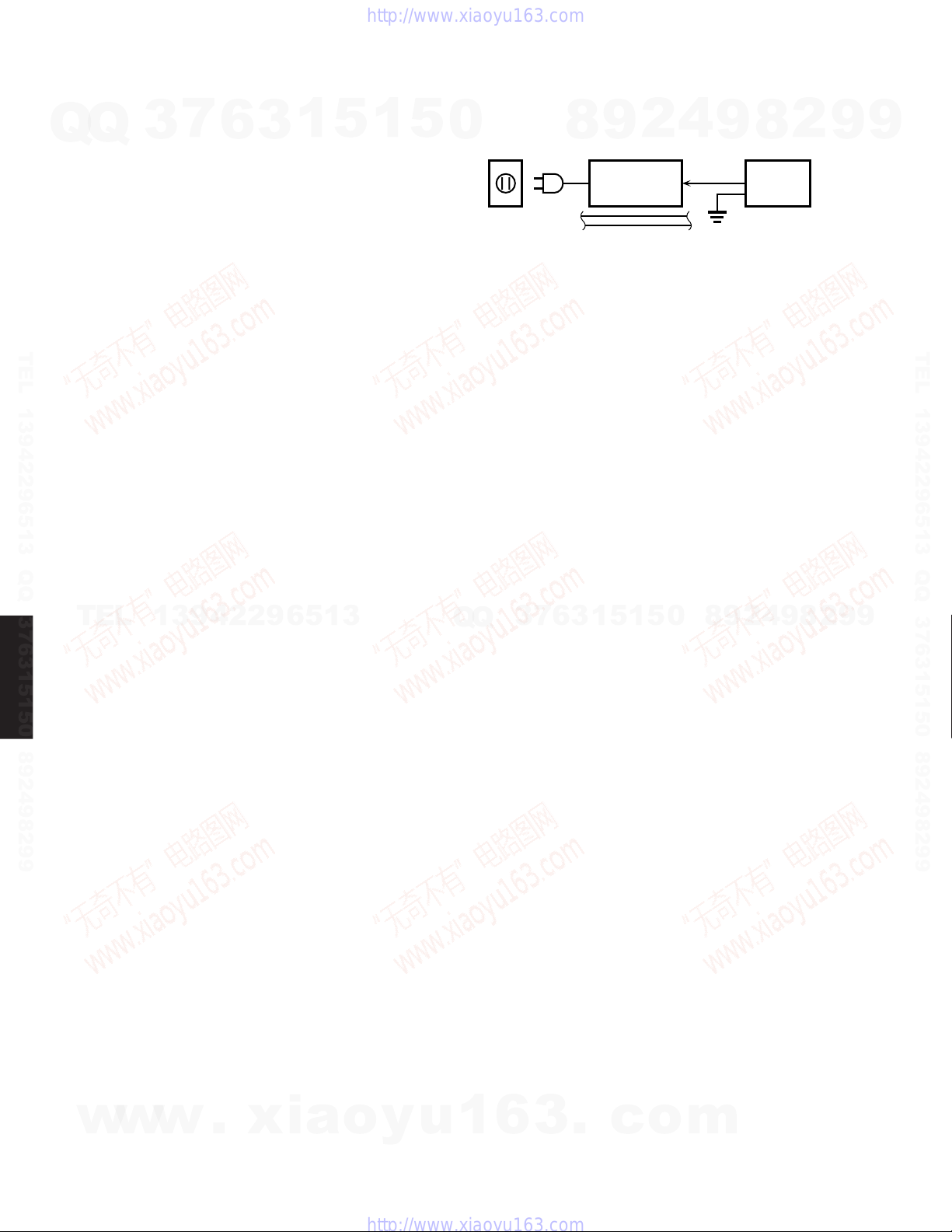
2. Leakage Current Measurement (For 120V Models Only)
When service has been completed, it is imperative to verify
that all exposed conductive surfaces are properly insulated
from supply circuits.
● Meter impedance should be equivalent to 1500 ohm shunted
by 0.15µF.
● Leakage current must not exceed 0.5mA.
● Be sure to test for leakage with the AC plug in both polarities.
3
7
6
3
1
5
1
5
0
WALL
OUTLET
9
8
EQUIPMENT
UNDER TEST
INSULATING
TABLE
2
4
AC LEAKAGE
8
9
TESTER OR
EQUIVALENT
2
9
9
TEL 13942296513 QQ 376315150 892498299
DVD-S2300MK2
THE DVD PLAYER SHOULD NOT BE ADJUSTED OR REPAIRED BY ANYONE EXCEPT PROPERLY QUALIFIED
SERVICE PERSONNEL.
WARNING: CHEMICAL CONTENT NOTICE!
The solder used in the production of this product contains LEAD. In addition, other electrical/electronic and/or plastic (where
applicable) components may also contain traces of chemicals found by the California Health and Welfare Agency (and
possibly other entities) to cause cancer and/or birth defects or other reproductive harm.
DO NOT PLACE SOLDER, ELECTRICAL/ELECTRONIC OR PLASTIC COMPONENTS IN YOUR MOUTH FOR ANY REASON WHATSOEVER!
Avoid prolonged, unprotected contact between solder and your skin! When soldering, do not inhale solder fumes or expose
eyes to solder/flux vapor!
If you come in contact with solder or components located inside the enclosure of this product, wash your hands before
handling food.
TEL
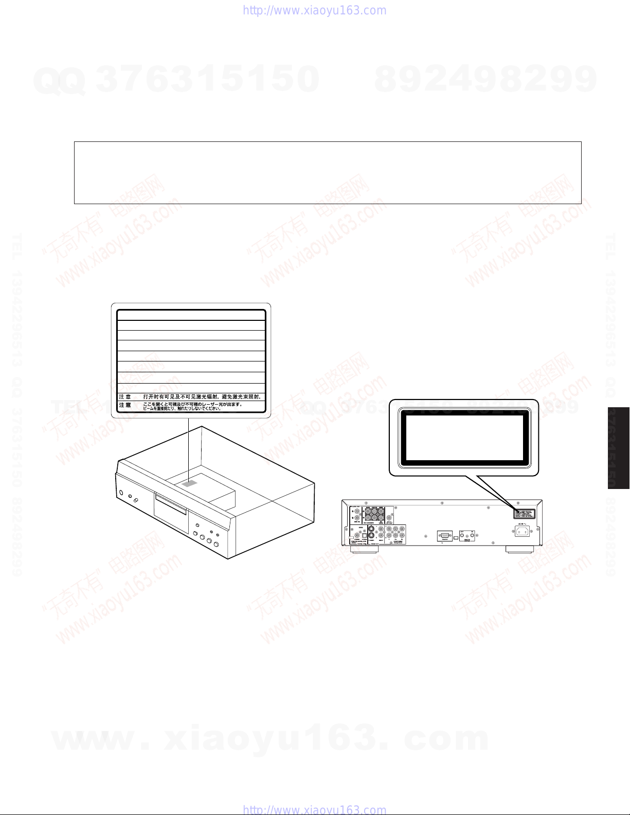
WARNING: Laser Safety
This product contains a laser beam component. This component may emit invisible, as well as visible radiation, which may
cause eye damage. To protect your eyes and skin from laser radiation, the following precautions must be used during
servicing of the unit.
1) When testing and/or repairing any component within the product, keep your eyes and skin more than 30 cm away from
the laser pick-up unit at all times. Do not stare at the laser beam at any time.
13942296513
Q
Q
3
7
6
3
1
5
1
5
0
8
9
2
4
9
8
2
9
TEL 13942296513 QQ 376315150 892498299
9
2) Do not attempt to readjust, disassemble or repair the laser pick-up, unless noted elsewhere in this manual.
3) CAUTION : Use of controls, adjustments or performance of procedures other than those specified herein may result in
hazardous radiation exposure.
Laser Emitting conditions:
1) When the Top Cover is removed, and the "POWER" SW is turned to the "ON" position, the laser component will emit a
beam for several seconds to detect if a disc is present. During this time (5-10 sec.) the laser may radiate through the lens
of the laser pick-up unit. Do not attempt any servicing during this period!
If no disc is detected, the laser will stop emitting the beam. When a disc is set, you will not be exposed to any laser
emissions.
2) The laser power level can be adjusted with the VR on the pick-up PWB. However, this level has been set by the factory
prior to shipping from the factory. Do not adjust this laser level control unless instruction is provided elsewhere in this
manual.
Adjustment of this control can increase the laser emission level from the device.
w
w
w
2
.
xia
o
y
u
1
6
3
.
c
o
m
Q
Laser Diode Properties
Type: Semiconductor laser GaAlAs
Wave length: 658 nm (DVD)
Q
Output Power: CLASS IIa 1mW (DVD)
VARO! : AVATTAESSA JA SUOJALUKITUS OHITETTAESSA OLET ALTTIINA NÄKYMÄTTÖMÄLLE LASER-
VARNING!: OSYNLIG LASERSTRÅLNING NÄR DENNA DEL ÄR ÖPPNAD OCH SPÄRREN ÄR URKOPPLAD.
3
7
6
790 nm (VCD/CD)
CLASS I 1mW (VCD/CD)
SÄTEILYLLE. ÄLÄ KATSO SÄTEESEEN.
BETRAKTA EJ STRÅLEN.
3
1
5
1
5
0
8
9
2
4
9
DVD-S2300MK2
8
2
9
9
TEL 13942296513 QQ 376315150 892498299
WARNING
Theuseofopticalinstrumentswiththisproductwillincreaseeyehazard.
Repairhandlingshouldtakeplaceasmuchaspossiblewithadiscloadedinsidetheplayer
-
VISIBLE AND INVISIBLE LASER RADIATION WHEN OPEN.
TEL
DANGER
AVOID DIRECT EXPOSURE TO BEAM.
-
VISIBLE AND INVISIBLE LASER RADIATION WHEN OPEN.
CAUTION
AVOID EXPOSURE TO BEAM.
-
RAYONNEMENT LASER VISIBLE ET INVISIBLE EN CAS D’OUVERTURE.
ATTENTION
EXPOSITION DANGEREUSE AU FAISCEAU.
-
SYNLIG OG USYNLIG LASERSTRÅLING VED ÅBNING.
ADVARSEL
UNDGÅ UDSÆTTELSE FOR STRÅLING.
-
AVATTAESSA OLET ALTTIINA NÄKYVÄÄ JA NÄKYMÄTÖN
VARO !
LASERSÄTEILYLLE. ÄLÄ KATSO SÄTEESEEN.
-
SYNLIG OCH OSYNLIG LASERSTRÅLNING NÄR DENNA DEL
VARNING
ÄR ÖPPNAD. BETRAKTA EJ STRÅLEN.
-
SYNLIG OG USYNLIG LASERSTRÅLING NÅR DEKSEL ÅPNES.
ADVARSEL
UNNGÅ EKSPONERING FOR STRÅLEN.
-
SICHTBARE UND UNSICHTBARE LASERSTRAHLUNG, WENN ABDECKUNG
VORSICHT
GEÖFFNET. NICHT DEM STRAHL AUSSETZEN.
-
13942296513
-
(FDA 21 CFR)
(IEC60825-1)
RQLS0233
Q
Q
3
7
6
3
0
5
1
5
1
CLASS 1 LASER PRODUCT
LASER KLASSE 1 PRODUKT
LUOKAN 1 LASERLAITE
KLASS 1 LASER APPARAT
PRODUIT LASER DE CLASSE 1
8
9
2
4
9
8
2
9
9
TEL 13942296513 QQ 376315150 892498299
DVD-S2300MK2
w
w
w
.
xia
o
y
u
1
6
3
.
c
o
m
3
DVD-S2300MK2
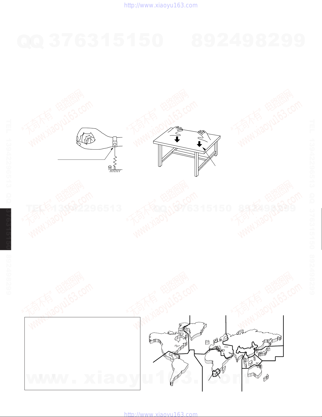
■ PREVENTION OF ELECTRO STATIC DISCHARGE
The laser diode in the traverse unit (optical pickup) may be damaged due to static electricity from clothes or the human body.
Q
Q
Use caution to prevent electrostatic damage when servicing or handling the laser diode.
1. Grounding for Electrostatic Damage Prevention
Some devices, such as the DVD player, use an optical pickup (laser diode) that will be damaged by static electricity in the
working environment. Only attempt service after ensuring that all grounding procedures have been completed.
1. Worktable grounding
Put a grounded conductive material (sheet) or iron sheet on the area where the optical pickup is placed.
2. Human body grounding
TEL 13942296513 QQ 376315150 892498299
Use an anti-static wrist strap to discharge the static electricity from your body.
7
3
Anti-static wrist strap
6
3
1
5
1
5
0
8
9
2
4
9
8
2
9
9
TEL 13942296513 QQ 376315150 892498299
2. Handling of the Optical Pickup
1. To prevent damage to the optical pickup replacement parts during transportation and before installation, both ends of the
laser diode are short-circuited. After installing the new part, remove the short circuit according to the correct procedure in
TEL
this service manual.
2. Do not use a tester to check the laser diode in the optical pickup. The power supply in the tester will damage the laser
diode.
3. Handling Precautions for the Traverse Unit (Optical Pickup)
DVD-S2300MK2
1. Handle the traverse unit (optical pickup) gently, as it is an extremely high-precision assembly.
2. The flexible cable lines may break if an excessive force is applied to it. Use caution when handling the cable.
3. The semi-fixed resistor for laser power adjustment should not be adjusted. Do not turn the resistor.
■ LOCALE MANAGEMENT INFORMATION
Locale Management Information : This DVD player is designed and manufactured to respond to the Locale Management
Information that is recorded on the DVD disc. If the Locale number described on the DVD disc does not correspond to the
Locale number of this DVD player, this DVD player cannot play this disc.
1M
13942296513
Q
Q
3
7
6
3
Conductive material
(sheet) or iron sheet
5
1
5
1
0
8
9
2
4
9
8
2
9
9
This product incorporates copyright protection
technology that is protected by method claims of
certain U.S. patents and other intellectual
property rights owned by Macrovision
Corporation and other rights owners. Use of this
copyright protection technology must be
authorized by Macrovision Corporation, and is
intended for home and other limited viewing uses
only unless otherwise authorized by Macrovision
Corporation. Reverse engineering or
w
w
disassembly is prohibited.
4
w
.
xia
1
4
o
y
u
1
6
3
.
2
2
c
5
o
5
m
5
6
3
2
4
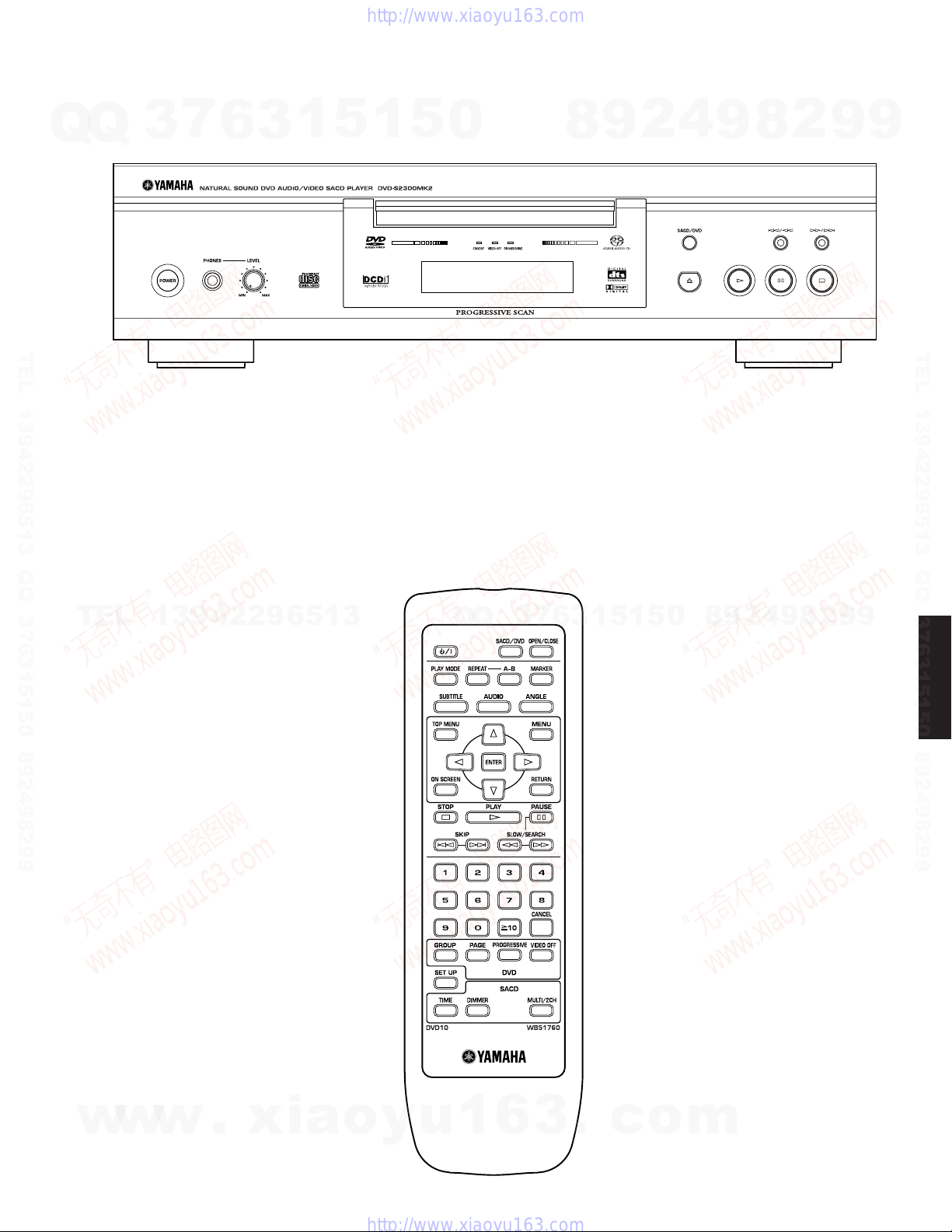
■ FRONT PANEL
DVD-S2300MK2
Q
TEL 13942296513 QQ 376315150 892498299
U model
Q
■ REMOTE CONTROL PANEL
U model
3
7
6
3
1
5
1
5
0
8
9
2
4
9
8
2
9
9
TEL 13942296513 QQ 376315150 892498299
TEL
13942296513
Q
Q
3
7
6
3
1
5
1
5
0
8
9
2
4
9
8
2
9
9
DVD-S2300MK2
w
w
w
.
xia
o
y
u
1
6
3
.
c
o
m
5
DVD-S2300MK2
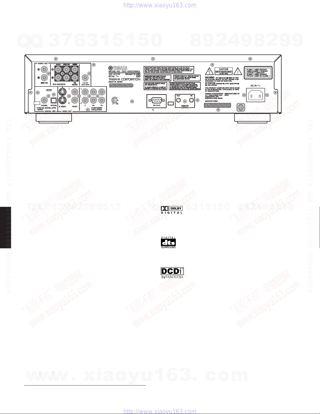
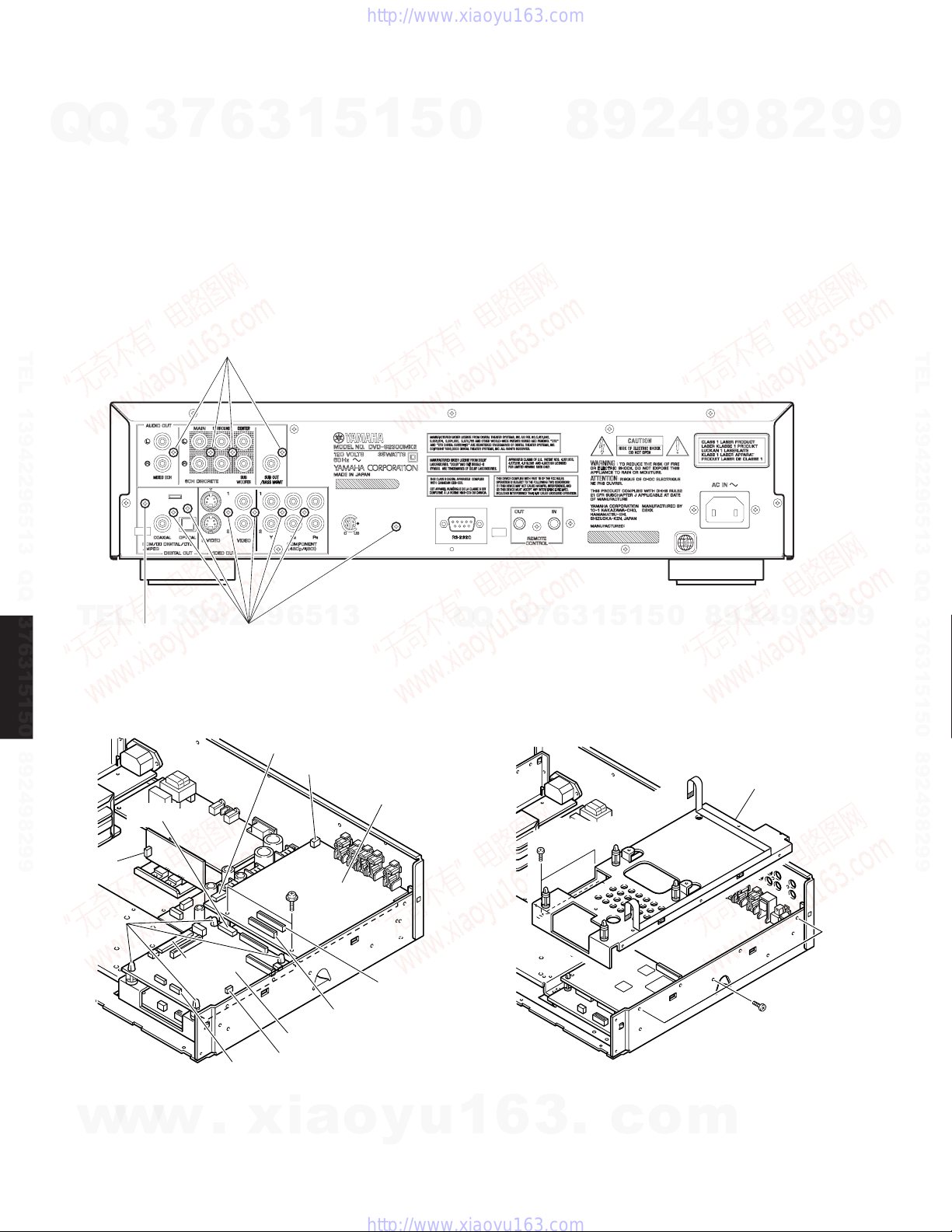
■ REAR PANEL
U model
Q
Q
TEL 13942296513 QQ 376315150 892498299
■ SPECIFICATIONS
Output Level
SACD/DVD/VIDEO CD/CD-DA (1kHz 0dB) ................2 V ± 0.3 V
Signal to Noise Ratio
SACD/DVD/VIDEO CD/CD-DA ......................................... 115 dB
Dynamic Range
SACD ................................................................................. 108 dB
DVD (48kHz, 24bit) ............................................................ 103 dB
VIDEO-CD/CD-DA ............................................................... 99 dB
TEL
Harmonic Distortion
SACD ............................................................................. 0.0016 %
DVD (48kHz, 24bit) ........................................................ 0.0020 %
VIDEO-CD/CD-DA ......................................................... 0.0022 %
Frequency Response
DVD ........................................... 2 Hz - 22 kHz (48 kHz sampling)
DVD-S2300MK2
DVD Audio .............................. 2 Hz - 88 kHz (192 kHz sampling)
VIDEO-CD/CD-DA ................................................... 2 Hz - 20 kHz
Video Output
........................................................................... 1 Vp-p (75 ohms)
S Video Output
Y ........................................................................ 1 Vp-p (75 ohms)
C ..................................................... NTSC: 0.286 Vp-p (75 ohms)
Component Video Output
Y ........................................................................ 1 Vp-p (75 ohms)
Pb ................................................................... 0.7 Vp-p (75 ohms)
Pr .................................................................... 0.7 Vp-p (75 ohms)
Digital Output Terminal
.................................................................. Optical x 1, Coaxial x 1
Other Equipment
........................................................................... RS-232C terminal
Power Supply
U model ................................................................AC 120 V, 60Hz
Power Consumption
U model ................................................................................. 35 W
Standby Power Consumption
.............................................................................................. 0.8 W
Dimensions (W x H x D)
....................................................................... 435 x 116 x 350 mm
Weight
.................................................................... 9.0 kg (19 lbs. 13 oz.)
Finish
.................................................................... Black Color (U model)
Accessories
Remote Control, Batteries x 2 (AA, R6, UM-3),
Audio/Video Cable, Power Cable
w
w
3
7
6
3
1
13942296513
2 Hz - 44 kHz (96 kHz sampling)
RemoteControlterminal
(17-1/8" x 4-9/16" x 13-3/4")
w
.
xia
5
o
1
y
5
u
0
* Specifications are subject to change without notice due to product
improvements.
U .......... U.S.A. model
7
3
Q
Q
Manufactured under license from Dolby Laboratories.
“Dolby”, “Pro Logic” and the double-D symbol are trademarks of
Dolby Laboratories.
“DTS” and “DTS Digital Surround” are registered trademarks of
Digital Theater Systems, Inc.
“DCDi” is a trademark of Faroudja, a division of Genesis
Microchip Inc.
1
6
3
6
8
3
.
9
1
1
5
c
2
5
o
4
0
m
9
8
9
8
2
4
2
9
8
9
2
9
9
TEL 13942296513 QQ 376315150 892498299
9
6
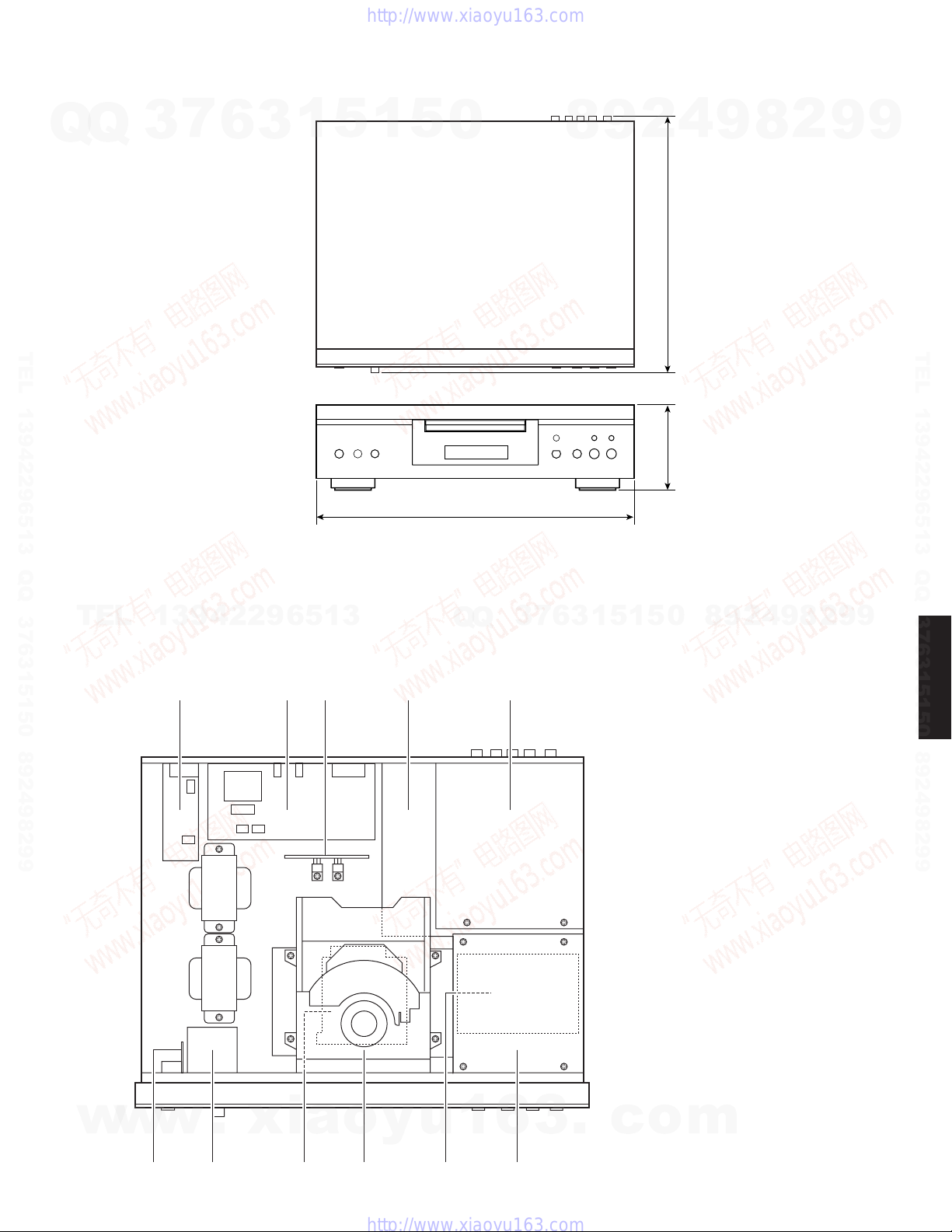
DIMENSIONS
DVD-S2300MK2
7
Q
Q
TEL 13942296513 QQ 376315150 892498299
3
6
3
1
5
1
5
0
435 (17-1/8")
9
8
Unit : mm (inch)
4
2
116 (4-9/16") 350 (13-3/4")
9
8
2
9
9
TEL 13942296513 QQ 376315150 892498299
TEL
13942296513
■ INTERNAL VIEW
1 2
Q
Q
43 5
3
7
6
3
1
5
9
8
0
5
1
1 MAIN (4) P.C.B.
2 RS-232C P.C.B.
3 AUDIO (2) P.C.B.
4 MAIN (1) P.C.B.
5 AUDIO (1) P.C.B.
6 MAIN (5) P.C.B.
7 MAIN (3) P.C.B.
8 TERMINAL P.C.B.
9 DVD Mechanism
0 DVD Module P.C.B.
A SACD P.C.B.
2
4
9
8
2
9
9
DVD-S2300MK2
w
w
w
67
.
xia
o
y
u
1
6
9 A08
3
.
c
o
m
7
DVD-S2300MK2
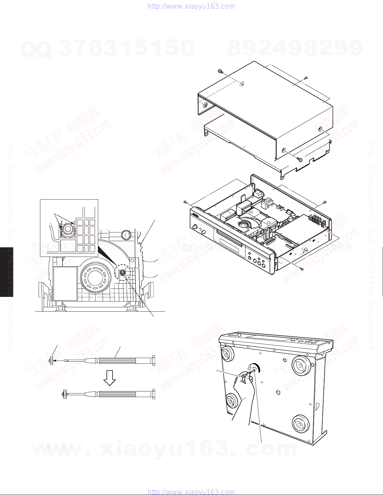
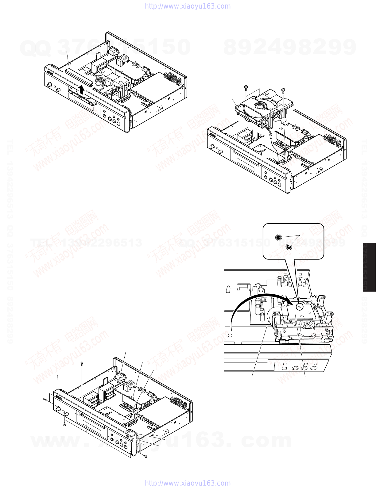
■ DISASSEMBLY PROCEDURES
(Remove parts in the order as numbered.)
Q
Q
Disconnect the power cable from the AC outlet.
1. Removal of Top Cover
a. Remove 4 screws (1) and 3 screws (2). (Fig. 1)
b.
Remove the top cover rearward while lifting it up. (Fig. 1)
2. Removal of Inner Cover
a. Remove 4 screws (3) and 2 screws (4). (Fig. 1)
b. Remove the inner cover. (Fig. 1)
3. Removal of Tray Lid
TEL 13942296513 QQ 376315150 892498299
a. Remove the Gear for opening the tray from the DVD-
Mechanism and install it onto a Screwdriver to make a
Gear Jig. (Fig. 2)
b. Insert the Gear Jig into the tray open/close hole. (Fig. 3)
c. Turn the Gear Jig counterclockwise to open the tray.
(Fig. 3)
d. Remove the Tray Lid from the tray section. (Fig. 4)
Cut
3
7
6
3
1
5
DVD-Mechanism
1
5
0
1
3
8
9
2
4
9
1
8
2
2
4
9
9
TEL 13942296513 QQ 376315150 892498299
TEL
DVD-S2300MK2
Gear
13942296513
Gear for opening the tray
Screwdriver
<Gear Jig>
Keep the Gear after using
Q
Q
Gear Jig
3
7
6
3
1
5
1
OPEN
5
Fig. 1
0
8
9
2
3
4
9
8
2
9
9
8
w
w
w
Fig. 2
.
xia
o
y
u
1
6
3
Tray open/close hole
.
c
o
Fig. 3
m
DVD-S2300MK2
Tray Lid
Q
Q
TEL 13942296513 QQ 376315150 892498299
4. Removal of DVD-mechanism
CAUTION
• When removing the DVD-Mechanism, make sure to follow steps
a. to e. below in that order to prevent the laser diode from being
damaged.
• When installing the DVD-Mechanism, make sure to follow in the
reverse order (from e. to a.) of the following procedure.
a. Remove 4 screws (5). (Fig. 5)
b. Turn over the DVD-Mechanism. (Fig. 6)
c. Solder the lands (SL5001/SL5002) in the Terminal P.C.B.. (Fig.
6)
Notes
TEL
• Use an anti-static soldering iron to short-circuit and unshortcircuit laser diode.
• After you have finished repairing the laser diode, follow the
correct procedure to remove the solder from the short-circuit
location.
d. Disconnect the connectors CB1 and CB6. (Fig. 5)
e. Remove the DVD-Mechanism.
7
3
13942296513
6
3
Fig. 4
1
5
1
5
0
Q
Q
DVD-Mechanism
7
3
6
8
3
9
1
5
5
2
3 x 10 -8
5
1
4
CB6
Fig. 5
SL5002
0
9
5
9
8
SL5001
8
3 x 10 -8
CB1
Solder
4
2
2
9
8
9
2
9
9
9
TEL 13942296513 QQ 376315150 892498299
DVD-S2300MK2
5. Removal of Front Panel Unit
a. Remove 4 screws (6) and 1 screws (7). (Fig. 7)
b. Remove 4 screws (8) (Fig. 7)
c. Disconnect the connectors CB10, CB602, CB605, CB803 and
CB822 and then remove the Front Panel Unit. (Fig. 7)
CB803
6
3 x 8
w
w
Front Panel
Unit
8
3 x 8
Bonding
w
7
3 x 8
Bonding
.
xia
Fig. 7
CB822
CB602
y
6
CB10
u
CB605
o
3 x 8
1
6
3
.
Flexible Cable
c
o
Terminal P.C.B.
Fig. 6
m
9
DVD-S2300MK2
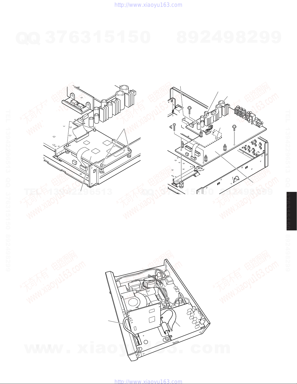
6. Removal of AUDIO P.C.B.
a. Remove 4 screws (9). (Fig. 8)
b. Disconnect the connectors CB301 ~ CB304 and CB650. (Fig. 9)
Q
Q
c. Remove 2 screws (0) and then remove the AUDIO (1) P.C.B. (Fig. 9)
7. Removal of SACD P.C.B.
a. Disconnect the connectors CB3, CB12 ~ CB14. (Fig. 9)
b. Remove the SACD P.C.B. with the tip of the 4 Support pinched with pliers or the
like. (Fig. 9)
8. Removal of Support/P.C.B.
a. Remove 1 screws (A). (Fig. 8)
b. Remove 5 screws (B) and then remove the Support / P.C.B. (Fig. 10)
3
7
6
3
1
5
1
5
0
8
9
2
4
9
8
2
9
9
TEL 13942296513 QQ 376315150 892498299
TEL
DVD-S2300MK2
CB650
13942296513
AC
CB12
9
CB303
0
CB304
3 x 10 -8
AUDIO P.C.B.
Q
Fig. 8
Q
3
7
B
6
3
3 x 8
1
5
1
5
0
2
9
8
Support / P.C.B.
4
9
8
2
9
TEL 13942296513 QQ 376315150 892498299
9
10
Support
w
w
CB3
w
CB13
Fig. 9
.
xia
SACD P.C.B.
CB14
CB301
CB302
o
y
u
1
6
3
.
c
Fig. 10
o
m
3 x 8
B
D
E
F
MAIN (1) P.C.B.
CB609
3 x 20
3 x 15
-8
3 x 10 -8
CB608
CB823
CB606
Q
9. Removal of DVD Module P.C.B.
Remove the DVD module P.C.B. with the tip of the 4 Support pinched with pliers or
the like. (Fig. 11)
Q
10.Removal of MAIN P.C.B.
a. Disconnect the connectors CB606, CB608, CB609 and CB823. (Fig. 12)
b. Remove 7 screws (C). (Fig. 8)
c. Remove 1 screw (D and E) and remove 2 screws (F) and then remove the MAIN
(1) P.C.B. (Fig. 12)
3
7
6
3
1
5
1
5
0
8
9
2
4
9
DVD-S2300MK2
2
8
9
9
TEL 13942296513 QQ 376315150 892498299
Support
Support
TEL
13942296513
Checking the SACD P.C.B.
• After removing the top cover and inner cover, remove the SACD P.C.B.
Set the SACD P.C.B. upright with its right side upward. (Fig. 13)
• Replace the cables connected to the SACD P.C.B. with the following extension
cables for servicing. (Fig. 13)
DVD Module P.C.B.
Fig. 11 Fig. 12
Q
Q
3
7
6
3
1
5
1
5
0
8
9
2
4
9
8
2
9
9
TEL 13942296513 QQ 376315150 892498299
DVD-S2300MK2
w
35-pin extension cable (200mm) : MFA35200
15-pin extension cable (200mm) : MFA15200
.
xia
15pin
o
w
w
y
u
1
6
3
.
Fig. 13
35pin
c
o
m
11
DVD-S2300MK2
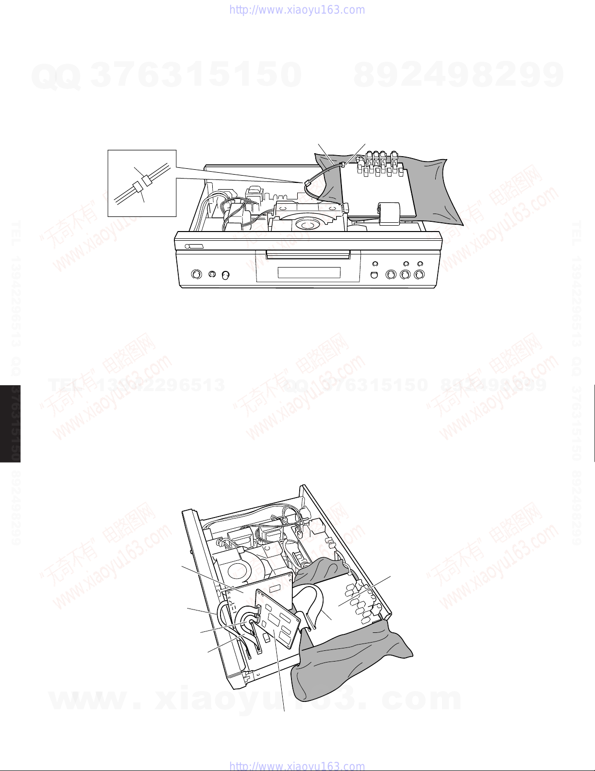
Checking the AUDIO P.C.B.
• After removing the top cover and inner cover, remove the AUDIO P.C.B.
Set the AUDIO P.C.B. upright with its rear panel side upward. (Fig. 14)
Q
Q
• Disconnect the cable connected to the AUDIO P.C.B. and then reconnect it via the
following extension cable for servicing. (Fig. 14)
3-pin extension cable (100mm) : VM017100
3
7
6
3
1
5
1
5
0
8
9
2
4
9
8
2
9
9
Connect with care to the polarity.
Yellow
TEL 13942296513 QQ 376315150 892498299
Checking the DVD Module P.C.B.
• With the top cover, inner cover and Support / P.C.B. removed, spread cloth over
the MAIN P.C.B. and place the AUDIO P.C.B. on it. Set the SACD P.C.B. and DVD
TEL
Module P.C.B. with their right side upward. (Fig. 15)
• Replace the cables connected to the SACD P.C.B. and DVD Module P.C.B. with
the following extension cables for servicing. (Fig. 14)
13942296513
White
Extension cable
Fig. 14
Q
Q
3
7
6
CB508
3
1
5
1
5
0
8
9
2
4
9
8
2
9
TEL 13942296513 QQ 376315150 892498299
9
35-pin extension cable (200mm) : MFA35200
DVD-S2300MK2
15-pin extension cable (200mm) : MFA15200
26-pin extension cable (JGS0098) : TX946370
22-pin extension cable (JGS0116) : AAX16610
w
w
w
SACD P.C.B.
.
xia
15pin
22pin
26pin
o
y
u
1
DVD Module P.C.B.
6
35pin
3
AUDIO P.C.B.
.
c
o
m
12
Fig. 15
Q
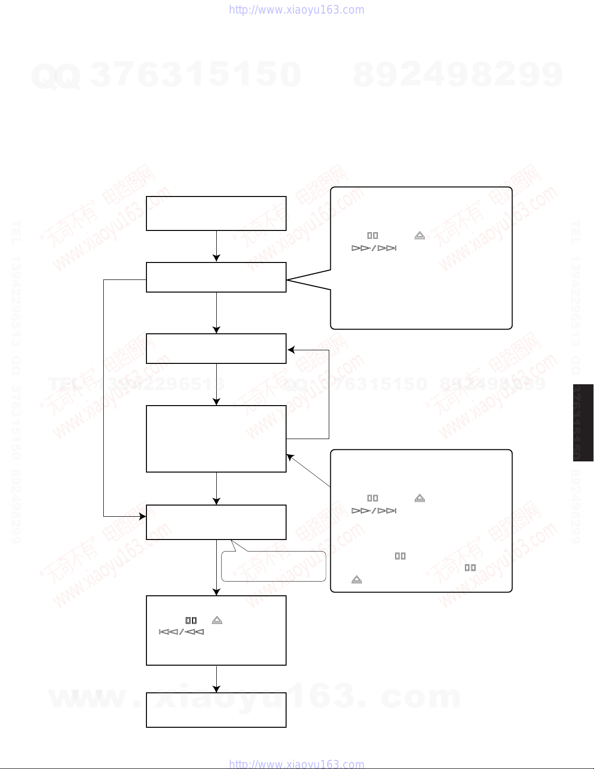
■ OPTICAL PICKUP SELF-DIAGNOSIS AND REPLACEMENT PROCEDURE
An optical pickup self-diagnosis function and tilt adjustment check function have been included in this unit. When repairing,
Q
use the following procedure for effective Self-diagnosis and tilt adjustment. Be sure to use the self-diagnosis function before
replacing the optical pickup when "NO DISC" is displayed. As a guideline, you should replace the optical pickup when the
value of the CD laser drive current is more than 55 (70 for DVD).
Note:
• Check the value within three minutes after applying the power to the player. (When the unit warms up, the result will be
incorrect.)
• Be sure to perform the following operation in the DVD mode.
3
7
6
3
1
5
1
5
0
8
9
2
4
9
DVD-S2300MK2
2
8
9
9
TEL 13942296513 QQ 376315150 892498299
Value is 70 (DVD),
55 (CD) or less.
TEL
13942296513
"NO DISC" is displayed, unit
does not play smoothly, etc.
Check the laser drive current.
Value is more than
70 (DVD), 55 (CD).
Replace the optical pickup.
Check the laser drive current
after replacement.
• Write the present value into
the unit if it is 60 (DVD), 45
(CD) or less.
Do the optical pickup tilt
adjustment.
Use the tilt adjustment
check function.
Q
Q
3
7
Method: With no disc in the player:
Press the "ON SCREEN" button on
the remote control unit while pressing
the " " and " " (DVD) or
" "(CD) buttons on the
player.
[Display content]
LDD○○○ ○○○(DVD)
LDC○○○ ○○○(CD)
FactorySetting Presentvalue
Replace with a new optical pickup if the
preset value is more than 60 (DVD), 45
3
6
(CD).
Cause: Damage due to static electricity
Method: With no disc in the player:
Press the "ON SCREEN" button on
the remote control unit while pressing
the " " and " " (DVD) or
" "(CD) buttons on the
player.
Writing method:
Press the " " button on the remote
control unit while pressing " " and
" " buttons on the player.
1
5
1
during replacement.
5
0
8
9
2
4
9
8
2
9
9
TEL 13942296513 QQ 376315150 892498299
DVD-S2300MK2
w
w
w
Initialize the player.
Press " ", " " and
" " buttons on the
player for 3 seconds or
longer.
.
xia
When not repaired, check the
Module P.C.B.
o
y
u
1
6
3
.
c
o
m
13
DVD-S2300MK2
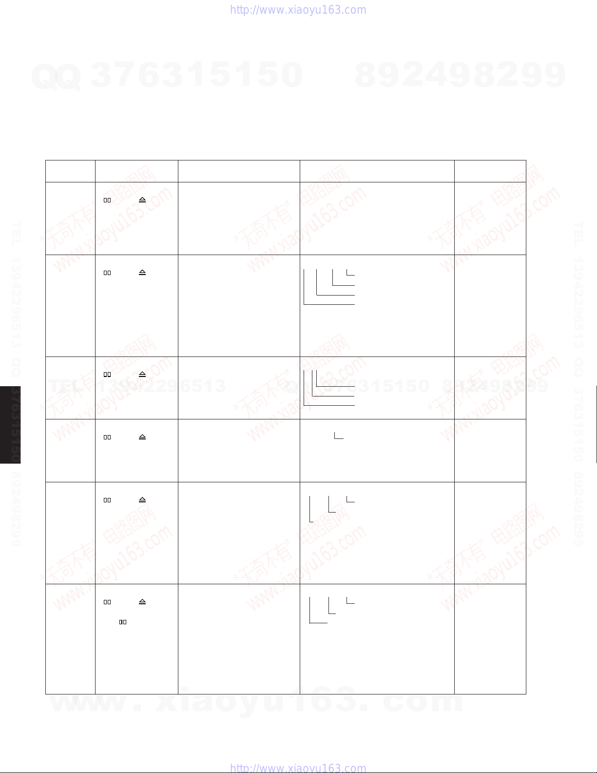
■ SERVICE MODE AND SELF-DIAGNOSIS FUNCTION
1. Service Mode
Q
Q
a. Turn on the POWER switch.
b. Press the SACD/DVD button to set to the DVD mode, and the DVD mode indicator lights up.
c. It is possible to use the following service modes, using the buttons on the player and the remote control unit in
combination.
Note: For jitter check, load the DVD test disc. [DVDT-S15 (AAX07320) or DVDT-S01]
Item
Error code In STOP mode, press The latest error code stored in Error code (play_err) is expressed in Cancelled
check " " and " " EEPROM is displayed. the following convention. automatically 5
TEL 13942296513 QQ 376315150 892498299
Jitter check In PLAY mode, press Jitter rate is measured and J_xxx_yyy_zz Press STOP or
Region In STOP mode, press The region numbers and video x_yy_zzz Cancelled
display " " and " " format are displayed. automatically 5
TEL
7
3
Player mode and
button combination method
buttons on the player,
and "0" button on the
remote control unit.
"
buttons on the player,
and "5" button on the
remote control unit.
buttons on the player, seconds later.
13942296513
and "6" button on the
remote control unit.
6
" and " " displayed. OPEN button.
3
1
5
1
5
0
Function Display
Error code = 0 x DAXX is expressed: → nn UXX
Error code = 0 x DBXX is expressed: → nn HXX
Error code = 0 x DXXX is expressed: → nn FXXX
Error code = 0 x 0000 is expressed: → nn F–––
* "nn" denotes the serial number of history.
↑ ↑ ↑ ↑
Jitter rate is shown in decimal notation to
one place of decimal.
Focus drive value is shown in
hexadecimal notation.
↑ ↑↑
7
3
Q
Q
9
8
Focusdrivevalue
Readerrorcounter
Jitterrate
Jittercheckmode
N:NTSC/6:PAL60
3
6
N:noPAL/P:PAL
RegionNo.
1
5
1
2
5
4
0
9
seconds later.
2
9
8
2
8
Cancellation
8
9
4
9
2
9
9
TEL 13942296513 QQ 376315150 892498299
9
Version In STOP mode, press DVD module firmware version srrr_xyzzzz Cancelled
display " " and " " is displayed. automatically 5
DVD-S2300MK2
DVD laser In STOP mode, press DVD laser drive current is LDD_034_032 Cancelled
drive current " " and " " measured and the result is automatically 5
measurement
Initial setting In STOP mode, press The initial current value for each LDO_034_028 Cancelled
of laser drive " " and " " DVD laser and CD laser is automatically 5
current buttons on the player, separetely saved in EEPROM. seconds later.
w
w
↑
buttons on the player, seconds later.
and "7" button on the
remote control unit.
↑ ↑ ↑
buttons on the player, displayed together with the initial seconds later.
and "ON SCREEN" value stored in EEPROM.
button on the remote After the measurement, DVD
control unit. laser emission is kept on. It is The value denotes the current in decimal
and " " button on
the remote control
unit. The value denotes the current in decimal
w
.
turned off when the "POWER" notation.
key is switched off. The above example shows the initial
xia
o
y
u
DVDlasercurrentmeasurementmode
current is 34mA and the measured value
is 32mA.
↑ ↑ ↑
Lasercurrentinitialsettingmode
notation. The above example shows the
initial current is 34mA and 28mA for DVD
laser and CD laser respectively when the
laser is switched on.
1
6
Versionnumber
Measuredcurrent
InitialcurrentstoredinEEPROM
CDlasercurrentmeasurement
DVDlasercurrentmeasurement
3
.
c
o
m
14
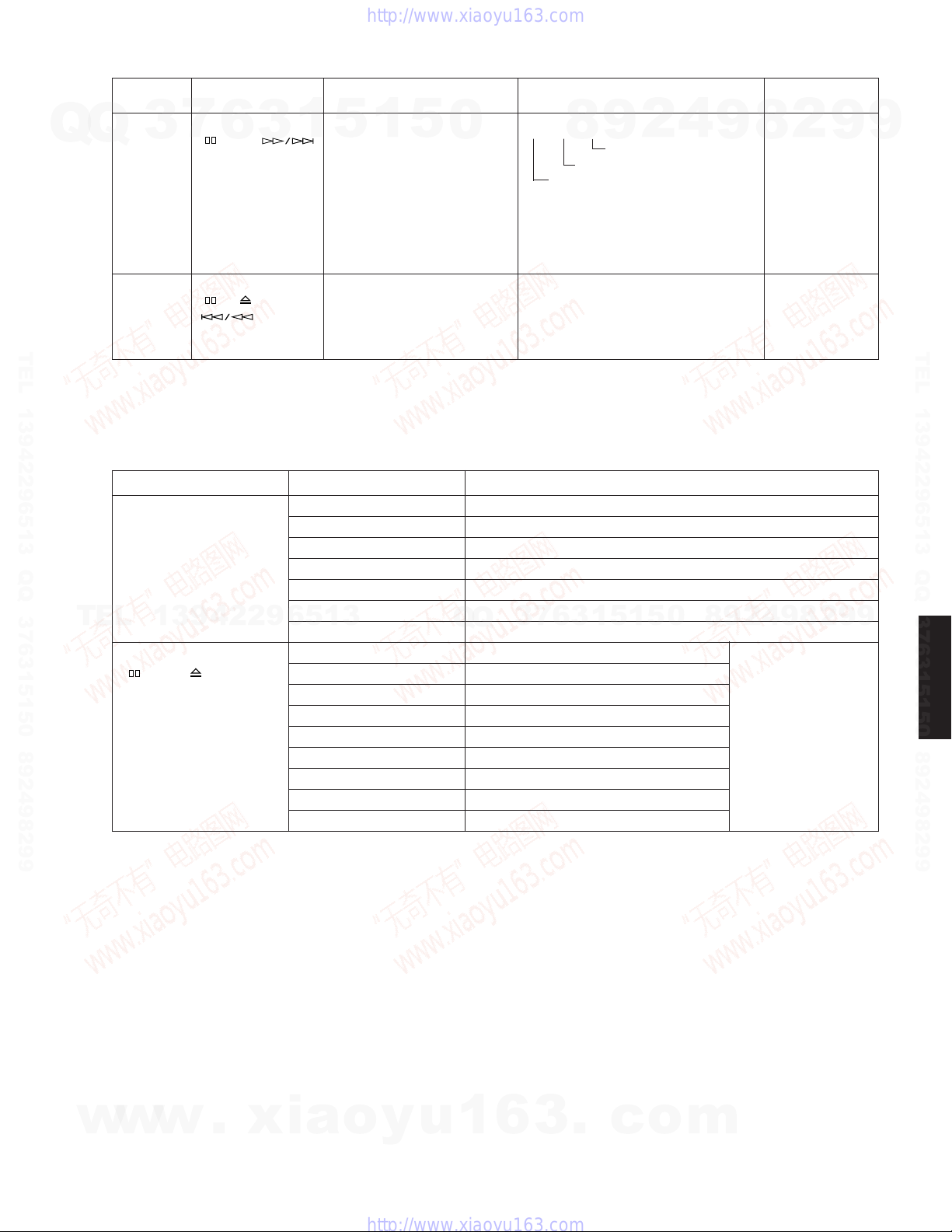
DVD-S2300MK2
Item
CD laser In STOP mode, press CD laser drive current is LDC_028_026 Cancelled
Q
Q
TEL 13942296513 QQ 376315150 892498299
TEL
3
drive current " " and " " measured and the result is automatically 5
measurement
DVD user In STOP mode, press All settings on the setup menu "Initialized" is displayed on the video
settings "
initialization " " buttons on
2. Self-Diagnosis Function (UHF Display)
This unit incorporates a convenient self-diagnosis function for use in troubleshooting.
Display method Display Diagnosis
Service numbers U11 Focus error
displayed during use. H01 Tray loading error
13942296513
In STOP mode, press F0** Disc format error
" " and " " buttons on F1** Disc code error
the player, and " 0 " button F2** Decoder LSI error
on the remote control unit. F3** SDRAM error
Player mode and
button combination method
7
6
buttons on the player, displayed together with the initial seconds later.
and "ON SCREEN" value stored in EEPROM.
button on the remote After the measurement, CD
control unit. laser emission is kept on. It is The value denotes the current in decimal
", " " and return to factory defaults. monitor connected to the player.
the player for 3
seconds or longer.
1
3
5
turned off when the "POWER" notation.
key is switched off. The above example shows the initial
H02
H03 Traverse error
H04 Tracking servo error
H05 Seek error
H06 Power supply error
F4** IIC BUS error Refer to error code.
F5** DSC error
F6** ECC error
F7** Microprocessor error
F8** Microprocessor error
Function Display
1
5
0
Spindle servo error
Q
Q
↑ ↑ ↑
current is 28mA and the measured value
is 26mA.
7
3
4
2
9
8
Measuredcurrent
InitialcurrentstoredinEEPROM
CDlasercurrentmeasurementmode
0
5
1
5
1
3
6
9
8
9
2
8
4
Cancellation
2
2
8
9
9
9
9
9
TEL 13942296513 QQ 376315150 892498299
DVD-S2300MK2
w
w
w
.
xia
o
y
u
1
6
3
.
c
o
m
15
DVD-S2300MK2
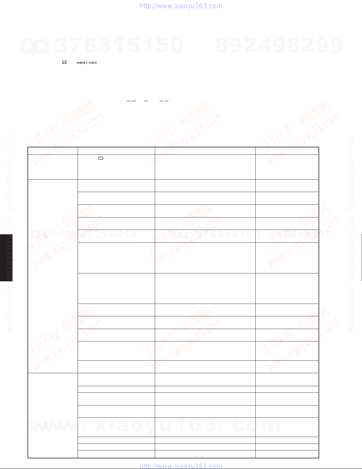
3. Test Mode
• Starting Test Mode
a. Turn on the POWER switch.
Q
Q
b. Press the SACD/DVD button to set to the SACD mode, and the SACD mode indicator lights up.
c. Press the "
test mode. At this time, the user setting of SACD mode returns to their factory settings.
• Display provided when Test Mode started
After all segments of the FL indicator light up, the firmware version of the panel microprocessor (IC40:
MN102HF60K) is displayed. Example:
• Canceling Test Mode
Turn off the POWER switch.
7
3
6
"+" " buttons on the player and the "PLAY" button on the remote control unit to start the
3
1
5
1
5
0
Ver L008
8
9
2
4
9
8
2
9
9
TEL 13942296513 QQ 376315150 892498299
DVD-S2300MK2
• List of Test Functions
Test functions available in the TEST mode are as follows.
DVD module
initialize
P.C.B. inspection
TEL
Servo test
w
16
Item
Press "
"CANCEL" on remote controller.
Press "TOP MENU" on remote
control unit.
Press "MENU" on remote
control unit.
Press "ANGLE" on remote
control unit.
Press "AUDIO" on remote
control unit.
13942296513
w
w
Press "PLAY MODE" on remote
control unit.
Every time the "MARKER"
button on the remote control
unit is pressed, pattern 1 or 2 is
selected alternately.
Every time the
"PROGRESSIVE" button on the
remote control unit is pressed,
the pattern 1, 2 or 3 is selected
one after another.
Press "DIMMER" on remote
control unit.
Press "REPEAT" on remote
control unit.
Press "A-B" on remote control
unit.
Press "STOP" on remote control
unit.
Press "VIDEO OFF" on remote
control unit.
Press "1" on remote control unit.
Press "2" on remote control unit.
Press "3" on remote control unit.
Press "4" on remote control unit.
Press "5" on remote control unit.
.
Press "6" on remote control unit.
Press "9" on remote control unit.
Press "0" on remote control unit.
Operation
" on main unit and
xia
o
Function
All the information included in DVD module
P.C.B. is initialized.
"Initialized" is displayed on the video
monitor connected to the player.
SODC DRAM write/read test
DSD DRAM test
EEPROM write/read test
DSD test signal output channel ON
Drive IC Mute OFF function
SHIFT register test output (2 patterns)
Pattern 1: DVD mode is displayed and
Pattern 2: SACD mode is displayed and
S terminal, D terminal, SCART terminal
control signal (3 patterns)
FL, LED test pattern output (All ON →
FL:12--9AB, LED:DVD/VOFF ON/ → OFF)
DVD laser ON
CD laser ON
Servo OFF, OSD test signal OFF, Analog
Mute ON, PANEL microprocessor version
display. Standby LED ON/OFF
Sub-CPU version is displayed.
Start-up of disc rotation from servo
initialize operation (1000rpm)
Focus ON from disc detection operation
Initial adjustment after focus ON: Focus
position rough adjustment DM CLV
Tracking balance adjustment and tracking
ON
Servo automatic adjustment (Focus
position adjustment, FO/TR gain
y
u
adjustment)
FEP equalizer EQ/Boost adjustment
Tracking ON
Tracking OFF
Q
Q
VIDEO OFF lights up.
PROGRESSIVE lights up.
1
3
6
7
3
6
3
.
1
1
5
c
FL Display
SODC DRAM OK or NG
DSD DRAM OK or NG
EEPROM OK or NG
TEST TONE
DrvMute Off
0
5
ShiftReg 55h
ShiftReg AAh
Video Mode 1 or 2 or 3
DVD Laser ON
CD Laser ON
Example: Ver L008
Example: SUB M004
Adj1 OK or ERR
Adj2 OK or ERR
Adj3 OK or ERR
Adj4 OK or ERR
Adj5 OK or ERR
o
m
Adj6 OK or ERR
Tr On OK or ERR
Tr Off OK or ERR
8
9
2
4
9
8
2
9
TEL 13942296513 QQ 376315150 892498299
9

DVD-S2300MK2
4. Sub-CPU RS-232C check mode
• Starting Sub-CPU RS-232C check mode
Q
TEL 13942296513 QQ 376315150 892498299
a. With the power turned off, short between pins No.2
Q
(RXD) and No.3 (TXD), and between pins No.7 (RTS)
and No.8 (CTS) of the RS-232C terminal.
Also pull-up pin No.3 (TXD) to 9-15V with the resistor
10 kΩ.
(Be suer to turn off the power when shorting the pins.)
b. Turn on the power and start the test mode. ( Refer to 3.
Test Mode on page 16. )
• Checking the RS-232C connection
1) Checking the connection between pins No.2 (RXD) and
No.3 (TXD)
a. Press "GROUP" key on remote control unit.
b. When the test has succeeded, "DIAG 0 OK" is
2) Checking the connection between pins No.7 (RTS) and
No.8 (CTS)
a. Press "PAGE" key on remote control unit.
b. When the test has succeeded, "DIAG 1 OK" is
TEL
• Canceling Sub-CPU RS-232C check mode
Turn off the power.
7
3
displayed after "UART DIAG 0".
When the test has failed, "DIAG ERR" is displayed
after "UART DIAG 0".
When "DIAG ERR" is displayed, check the pattern of
RXD and TXD line.
displayed after "UART DIAG 1".
When the test has failed, "DIAG ERR" is displayed
13942296513
after "UART DIAG 1".
When "DIAG ERR" is displayed, check the pattern of
RTS and CTS line.
6
3
1
5
1
5
0
Q
5. Service Precautions
5.1. Recovery After the DVD Player is Repaired
When the DVD module P.C.B., or a FROM or an EEPROM
on the DVD module P.C.B. has been replaced, carry out
the recovery disc procedure to optimize the drive.
Playback the disc below to perform the recovery
automatically,
Note:
When the recovery procedure is performed, the user
settings will be erased and the factory settings will be
restored as when the initialization procedure is used.
Therefore, it is necessary to write down the content of the
user settings before performing the recovery procedure
and reset it after that.
5.2. Firmware Version-Up of the DVD Module
The firmware of the DVD module may be updated to
improve the quality, including optimizing operationability
and playability with substandard discs.
The version-update disc also has a recovery function so
that you don't need to use the recovery disc again.
Detailed information on supply of the version-update disc
will be provided in Service News.
Note:
7
3
If the AC power supply is lost during version-updating due
Q
to a power failure, the version-update is improperly carried
out.
In such a case, replace the FROM and carry out the
version-update again.
If recovery by using the version-update disc has failed,
start up the TEST mode and initialize the DVD module.
(Refer to the description of the previous section.)
4
2
9
8
Recovery disc: RFKZD5TR006 (AAX42050)
0
5
1
5
1
3
6
9
8
9
2
8
4
2
9
8
9
2
9
9
9
TEL 13942296513 QQ 376315150 892498299
DVD-S2300MK2
w
w
w
.
xia
6. Handling After Completing Repairs
Usethefollowingprocedureaftercompletingrepairs.
6.1. Method
Confirm that the power is turned on:
1. Press the "OPEN/CLOSE" button to close the tray.
2. Turn off the POWER switch.
3. Disconnect the power plug from the outlet.
6.2. Precautions
Do not disconnect the power plug from the outlet with the
tray still open, then close the tray manually.
o
y
u
1
6
3
.
c
o
m
17

DVD-S2300MK2
7. Error Code
Description of error Supplementary explanation
7
Q
Q
U11
H01
H02
H03
H04
H05
H06
TEL 13942296513 QQ 376315150 892498299
DVD-S2300MK2
F500
F501
F502
F503
F505
F506
F600
F601
F602
F603
F610
TEL
F611
F612
F630
F631
F632
F103
F4FF
F700
F701
F702
F880
F890
F891
F893
F894
F8A0
OPU : Optical Pick Up, DSC : Digital Servo Controller, FEP : Front End Processor, ODC : Optical Disc Controller, FROM : Flash ROM
w
*1: CPPM is the copy guard function beforehand written in the disc for protection of copyrights.
3
L. H error
Focus error
Tray loading error
Spindle servo error
Traverse servo error
Tracking servo error
Seek error
Power supply error
DSC related error
DSC error
DSC not ready
DSC time out error To be handled in the same way as F500
DSC communication failure
DSC Attention Error To be handled in the same way as F500
Invalid media The disc is upside down, TOC cannot be read, unusable disc
ODC related error
No control data is obtainable due to a
demodulation error
Undefined sector ID is requested.
LEAD-IN is not obtainable due to
demodulation error.
KEY DET is not obtainable due to a
demodulation error
ODC abnormal Issuing a command is not permitted.
6626 QCODE don't read Error No seek address is obtainable in the CD system.
No CRC OK is issued for a certain time. No ID data is obtainable in the DVD system.
No response is provided for the inquiry of
KEY DET.
CPPM KEY DET is not usable until the
end of the file.
CPPM-KEY-DET is not usable. CPPM-KEY-DET is revoked or falsified.
Disc code
Illegal highlight position
IIC error
Forcible initialization failure (time-out)
Microprocessor error
MBX overflow
Message command does not end.
Message command is changed.
Incorrect task number
Message transmission is attempted while
transmitting to AV task
A message cannot be transmitted to AV
task.
FROM is falsified.
EEPROM abnormal
Message command is not correct.
13942296513
w
w
6
.
xia
3
1
5
1
5
0
(
Spindle servo, DSC SP motor, CLV servo error)
The power cannot be turned off due to a communication error
between the panel control and the system control.
DSC is stopped due to occurrence of a servo error.
(startup, focus error, etc.)
Communication error between DSC and system control
(communication failure due to DSC not at work)
Communication error (A communication command was
transmitted but an error occurred.)
Operation is stopped because the navigation data cannot be
obtained due to a faulty condition of the demodulation system
Operation is stopped due to a request for access by an
abnormal ID data.
LEAD IN data cannot be read.
The CSS data of the disc cannot be obtained.
7
3
Q
Q
(Only when used internally)
The CPPM file system cannot be read due to a scratch, etc.
It is highly possible that disc code is violated when displaying
the highlight.
When sending a message back to Disc Manager
Next message was issued before replying to Disc Manager.
The message is changed before replying to Disc Manager.
When a message comes from non-existing task (error stop,
firm bug correction required)
A message is being transmitted to AV task (error stop, firm
bug correction, etc.)
Transmission of a message to AV task is started. (error stop,
firm bug correction required)
Transmission of a message to AV task is started. (error stop,
firm bug correction required)
o
y
u
1
6
3
Faulty point 1 Faulty point 2 Faulty point 3 Faulty point 4
9
8
OPU
ADSC
(IC2001)
OPU
ADSC
(IC2001)
OPU
Disc
ODC
(IC2001)
ODC
(IC2001)
ODC
1
5
1
3
6
(IC2001)
ODC
(IC2001)
ODC
(IC2001)
Disc
Disc
Disc
EEPROM
(IC6221)
Firm bug
Firm bug
Firm bug
Firm bug
Firm bug
Firm bug
FROM
(IC6301)
EEPROM
(IC6221)
Firm bug
.
c
4
2
ADSC
(IC2001)
CPU
(IC6201)
ADSC
(IC2001)
FEP
(IC5201)
ADSC
(IC2001)
FEP
(IC5201)
FEP
(IC5201)
FEP
(IC5201)
0
5
CPPM (*1)
EEPROM
(IC6221)
CPU
(IC6201)
CPU
(IC6201)
Serial
communication
line
o
m
9
FEP
(IC5201)
FEP
(IC5201)
EEPROM
(IC6221)
FEP
(IC5201)
ADSC
(IC2001)
ADSC
(IC2001)
ADSC
(IC2001)
9
8
CPPM (*1)
FEP
(IC5201)
8
2
Servo drive
Servo drive
Servo drive
ODC
(IC2001)
9
4
ADSC
(IC2001)
2
8
9
2
9
9
TEL 13942296513 QQ 376315150 892498299
9
18
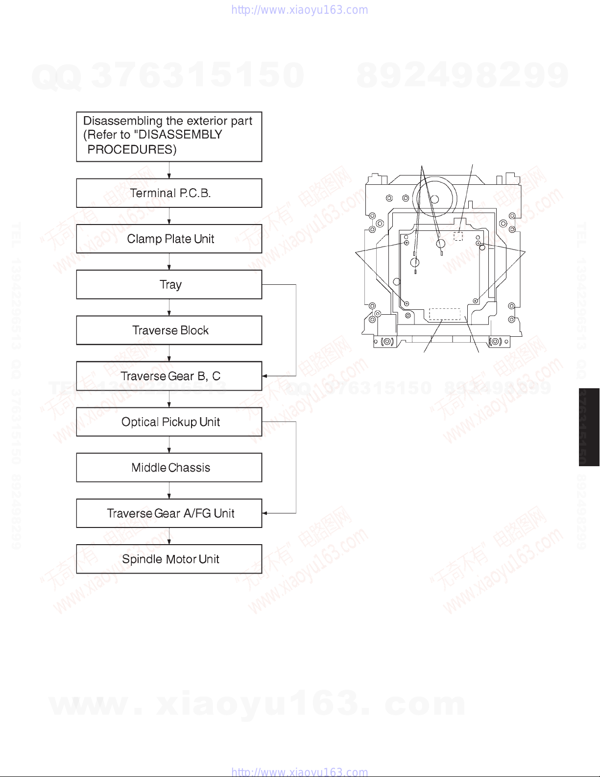
■ ASSEMBLING AND DISASSEMBLING THE MECHANISM UNIT
DVD-S2300MK2
7
Q
Q
TEL 13942296513 QQ 376315150 892498299
3
1. Disassembly Procedure 2. Terminal P.C.B.
6
3
1
5
1
5
0
1. Remove the screws.
2. Remove the solder from the motor connections.
3. Remove the connectors.
8
9
4
2
Solder Connector
9
8
TerminalP.C.B.Connector
2
9
ScrewScrew
9
TEL 13942296513 QQ 376315150 892498299
TEL
13942296513
Q
Q
3
7
6
<Mechanismunitbottom>
5
1
3
1
5
0
8
9
2
4
9
8
2
9
9
DVD-S2300MK2
w
w
w
.
xia
o
y
u
1
6
3
.
c
o
m
19
 Loading...