

Yamaha DVDC-961 Service Manual
DVD AUDIO/VIDEO SA-CD PLAYER
DVD-C961
SERVICE MANUAL
IMPORTANT NOTICE
This manual has been provided for the use of authorized YAMAHA Retailers and their service personnel.
It has been assumed that basic service procedures inherent to the industry, and more specifically YAMAHA Products, are already
known and understood by the users, and have therefore not been restated.
WARNING: Failure to follow appropriate service and safety procedures when servicing this product may result in personal
IMPORTANT: The presentation or sale of this manual to any individual or firm does not constitute authorization, certification or
The data provided is believed to be accurate and applicable to the unit(s) indicated on the cover. The research, engineering, and
service departments of YAMAHA are continually striving to improve YAMAHA products. Modifications are, therefore, inevitable
and specifications are subject to change without notice or obligation to retrofit. Should any discrepancy appear to exist, please
contact the distributor's Service Division.
WARNING: Static discharges can destroy expensive components. Discharge any static electricity your body may have
IMPORTANT: Turn the unit OFF during disassembly and part replacement. Recheck all work before you apply power to the unit.
injury, destruction of expensive components, and failure of the product to perform as specified. For these reasons,
we advise all YAMAHA product owners that any service required should be performed by an authorized
YAMAHA Retailer or the appointed service representative.
recognition of any applicable technical capabilities, or establish a principle-agent relationship of any form.
accumulated by grounding yourself to the ground buss in the unit (heavy gauge black wires connect to this buss).
■ CONTENTS
TO SERVICE PERSONNEL ...................................... 2–3
PREVENTION OF ELECTROSTATIC DISCHARGE .... 4
LOCALE MANAGEMENT INFORMATION ................... 4
FRONT PANEL .............................................................. 5
REAR PANEL ................................................................ 5
REMOTE CONTROL PANEL ........................................ 5
SPECIFICATIONS...................................................... 6–7
INTERNAL VIEW ........................................................... 7
101068
2007 All rights reserved.
This manual is copyrighted by YAMAHA and may not be copied or
redistributed either in print or electronically without permission.
DVD-C961
REPAIR NOTES............................................................. 7
DISASSEMBLY PROCEDURES ............................... 8–9
BLOCK DIAGRAM....................................................... 10
WIRING DIAGRAM ...................................................... 11
PRINTED CIRCUIT BOARDS................................ 12–22
SCHEMATIC DIAGRAMS...................................... 23–38
REPLACEMENT PARTS LIST .............................. 40–41
P.O.Box 1, Hamamatsu, Japan
'07.09

DVD-C961
■ TO SERVICE PERSONNEL
1. Critical Components Information
Components having special characteristics are
marked s and must be replaced with parts having
specifications equal to those originally installed.
2. Leakage Current Measurement (For 120V Models
Only)
When service has been completed, it is imperative to
verify that all exposed conductive surfaces are properly insulated from supply circuits.
● Meter impedance should be equivalent to 1500 ohms
shunted by 0.15µF.
WALL
OUTLET
● Leakage current must not exceed 0.5mA.
● Be sure to test for leakage with the AC plug in both
polarities.
EQUIPMENT
UNDER TEST
INSULATING
TABLE
AC LEAKAGE
TESTER OR
EQUIVALENT
WARNING: CHEMICAL CONTENT NOTICE!
This product contains chemicals known to the State of California to cause cancer, or birth defects or other reproductive
harm.
DO NOT PLACE SOLDER, ELECTRICAL/ELECTRONIC OR PLASTIC COMPONENTS IN YOUR MOUTH FOR ANY REASON WHAT SO EVER!
Avoid prolonged, unprotected contact between solder and your skin! When soldering, do not inhale solder fumes or expose
eyes to solder/flux vapor!
If you come in contact with solder or components located inside the enclosure of this product, wash your hands before
handling food.
About lead free solder
All of the P.C.B.s installed in this unit and solder joints are soldered using the lead free solder.
Among some types of lead free solder currently available, it is recommended to use one of the following types for the repair
work.
• Sn + Ag + Cu (tin + silver + copper)
• Sn + Cu (tin + copper)
• Sn + Zn + Bi (tin + zinc + bismuth)
Caution:
As the melting point temperature of the lead free solder is about 30°C to 40°C (50°F to 70°F) higher than that of the lead
solder, be sure to use a soldering iron suitable to each solder.
DVD-C961
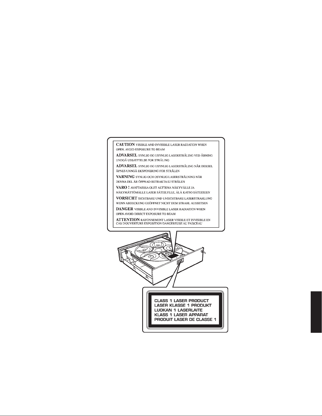
WARNING: Laser Safety
This product contains a laser beam component. This component may emit invisible, as well as visible radiation,
which may cause eye damage. To protect your eyes and skin from laser radiation, the following precautions must be
used during servicing of the unit.
1) When testing and/or repairing any component within the product, keep your eyes and skin more than 30 cm away from
the laser pick-up unit at all times. Do not stare at the laser beam at any time.
2) Do not attempt to readjust, disassemble or repair the laser pick-up, unless noted elsewhere in this manual.
3) CAUTION : Use of controls, adjustments or performance of procedures other than those specified herein may result in
hazardous radiation exposure.
2
DVD-C961
Laser Emitting conditions:
1) When the Top Cover is removed, and the STANDBY/ON SW is turned to the "ON" position, the laser component will emit
a beam for several seconds to detect if a disc is present. During this time (5-10 sec.) the laser may radiate through the
lens of the laser pick-up unit. Do not attempt any servicing during this period!
If no disc is detected, the laser will stop emitting the beam. When a disc is loaded, you will not be exposed to any laser
emissions.
2) The laser power level can be adjusted with the VR on the pick-up PWB, however, this level has been set by the factory
prior to shipping from the factory. Do not adjust this laser level control unless instruction is provided elsewhere in this
manual. Adjustment of this control can increase the laser emission level from the device.
Laser Diode Properties
Type: Semiconductor laser GaAlAs
Wave length: 650 nm (DVD)
780 nm (VCD/CD)
Output power: 7 mW (DVD/VCD/CD)
Beam divergence: 60 degrees
Warning for power supply
The primary side of the power supply carries live mains voltage when the pla yer is connected to the mains e ven when
the player is switched off !
This primary area is not shielded so it is possible to touch copper tracks and/or components when servicing the player.
Service personnel have to take precautions to prevent touching this area or components in this area.
Note:
The screws on the DVD mechanism may never be touched, removed or re-adjusted.
Handle the DVD mechanism with care when the unit has to be exchanged!
The DVD mechanism is very sensitive for dropping or giving shocks.
DVD-C961
3
DVD-C961
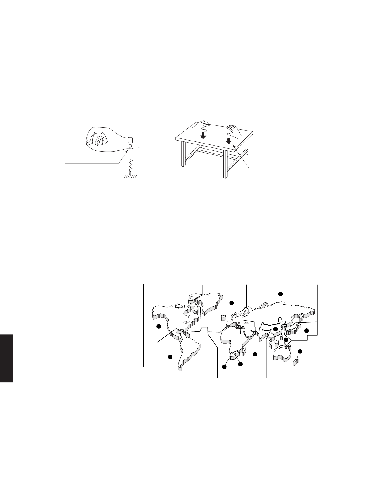
■ PREVENTION OF ELECTROSTATIC DISCHARGE
The laser diode in the DVD mechanism may be damaged due to static electricity from clothes or the human body. Use caution
to prevent electrostatic damage when servicing or handling the DVD-mechanism.
1. Grounding for electrostatic damage prevention
Some devices, such as the DVD player, use an optical pickup (laser diode) that will be damaged by static electricity in the
working environment. Only attempt service after ensuring that all grounding procedures have been completed.
1. Worktable grounding
Put a grounded conductive material (sheet) or iron sheet on the area where the optical pickup is placed.
2. Human body grounding
Use an anti-static wrist strap to discharge the static electricity from your body.
2. Handling Precautions for DVD mechanism
1. Handle the DVD mechanism gently, as it is an extremely high-precision assembly.
2. The flexible cable lines may break if an excessive force is applied to it. Use caution when handling the cable.
3. The semi-fixed resistor for laser power adjustment should not be adjusted. Do not turn the resistor.
■ LOCALE MANAGEMENT INFORMATION
Locale Management Information : This DVD player is designed and manufactured to respond to the Locale
Management Information that is recorded on a DVD disc. If the Locale number described on the DVD disc does not
correspond to the Locale number of this DVD player, this DVD player cannot play this disc.
This product incorporates copyright protection technology that is protected by method
claims of certain U.S. patents and other
intellectual property rights owned by
Macrovision Corporation and other rights
owners. Use of this copyright protection
technology must be authorized by Macrovision
Corporation, and is intended for home and
other limited viewing uses only unless otherwise authorized by Macrovision Corporation. Reverse engineering or disassembly
is prohibited.
DVD-C961
Anti-static wrist strap
1M-ohms
Conductive material
(sheet) or steel sheet
5
2
1
4
2
5
5
6
3
2
4
4
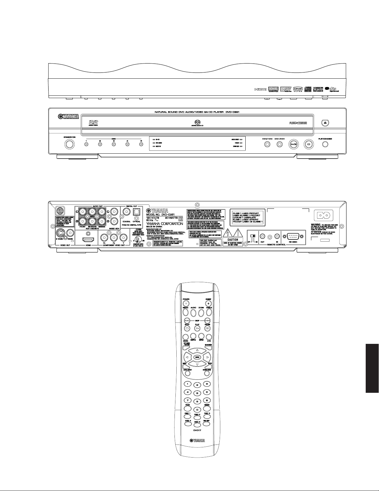
■ FRONT PANEL
U model
■ REAR PANEL
U model
DVD-C961
■ REMOTE CONTROL PANEL
DVD-C961
5

DVD-C961
■ SPECIFICATIONS
PLAYBACK SYSTEM
DVD-video, VR (video recording) format (DVD-RW)
DVD-audio
DVD-R, DVD-RW
DVD+R, DVD+RW, DVD+R DL
Video CD, SVCD
SA-CD multi-channel and SA-CD stereo
CD
Picture CD
CD-R, CD-RW
MP3 (ISO 9660) fs 16, 22.05, 24, 32, 44.1, 48 kHz /
WMA fs 44.1 kHz, 62 kbps to 192 kbps
DivX
JPEG 3072 x 2048 pixels or less
VIDEO PERFORMANCE
Video (CVBS) output 1 Vpp into 75 ohms
S-video output Y: 1 Vpp into 75 ohms
Component video output Y: 1 Vpp into 75 ohms
Black level shift On/Off
AUDIO FORMAT
Digital Dolby Digital, DTS, MPEG
Full decoding of Dolby Digital and DTS multi-channel sound
Analog stereo sound
Dolby surround compatible downmix from Dolby Digital multichannel sound
Dolby Pro Logic II
3D sound for virtual 5.1 channel sound on 2 speakers
AUDIO PERFORMANCE
DA converter 24 bits, 192 kHz
Signal to noise (1 kHz) 105 dB
Dynamic range (1 kHz) 100 dB
DVD fs 96 kHz 2 Hz to 44 kHz
SVCD fs 48 kH z 2 Hz to 22 kHz
DVD-C961
CD/VCD fs 44.1 kH z 2 H z to 20 k Hz
Distortion and noise (1 kHz)
TV STANDARD
Number of lines PAL: 625, NTSC: 525
Vertical frequency PAL: 50 Hz, NTSC: 60 H z
Playback Multistandard (PAL/NTSC)
HDMI video output 480 p/60 Hz, 576 p/50 Hz, 720 p/60 Hz,
CONNECTIONS
Video output RCA/Phono x 1 (yellow)
S-video output Mini DIN, 4 pins x 1
96, 128, 256 kbps (CBR only)
(CBR only) /
fs 48 kHz, 128 kbps to 192 kbps
(CBR only)
®
C: 0.3 Vpp into 75 ohms
PB/CB PR/CR: 0.7 Vpp into 75 ohms
Compressed digital
PCM fs 44.1, 48, 96 kHz /
16, 20, 24 bits
MP3 (ISO 9660) fs 16, 22.05, 24, 32, 44.1, 48 kHz /
24, 32, 56, 64, 96, 128, 256 kbps
WMA 32 kbps to 192 kbps,
mono, stereo
fs 48 kHz 2 Hz to 22 kHz
fs 44.1 kHz 2 Hz to 20 kHz
0.0035 %
1080 i/60 Hz, 1080 p/60 Hz
Component video output
Y output RCA/Phono x 1 (green)
PB output RCA/Phono x 1 (blue)
output RCA/Phono x 1 (red)
P
R
2-channel audio output (L+R)
RCA/Phono x 1 pair (white/red)
6-channel audio output
Audio front L/R RCA/Phono x 1 pair (white/red)
Audio surround L/R
RCA/Phono x 1 pair (white/red)
Audio center RCA/Phono x 1 (black)
Audio subwoofer RCA/Phono x 1 (black)
Digital output
Coaxial RCA/Phono x 1
IEC60958 for CDDA / LPCM, IEC61937
for MPEG2, Dolby Digital, DTS
Optical RCA/Phono x 1
IEC60958 for CDDA / LPCM, IEC61937
for MPEG2, Dolby Digital, DTS
HDMI (Ver. 1.1) Type A x 1
IEC60958 for CDDA / LPCM, IEC61937
for MPEG2, Dolby Digital, DTS
PCM (PPCM) multi / 2ch (DVD-audio),
PCM multi / 2ch (SA-CD)
Remote control
Input ø3.5 mm mini jack x 1
Output ø3.5 mm mini jack x 1
RS-232C D-sub 9 P
GENERAL
Dimensions (W x D x H) 435 x 425 x 75 mm
(17-1/8" x 16-3/4" x 2-15/16")
Weight Approx. 5.5 kg (12 lbs. 2 oz.)
Finish Black color
Power supply AC 120 V, 60 Hz
Power consumption Approx. 20 W
Standby power consumption Less than 0.5 W
ACCESSORIES
Remote control x 1
Battery (R6, AA, UM-3) x 2
Power cable (1.5 m) x 1
Audio/Video pin cable (1.5 m) x 1
* Specifications are subject to change without prior notice.
U ........ U.S.A. model
Manufactured under license from
Dolby Laboratories. “Dolby”, “Pro
Logic” and the double-D symbol are
trademarks of Dolby Laboratories.
“DTS” and “DTS Digital Surround”
are registered trademarks of DTS,
Inc.
“DCDi” is a trademark of Faroudja,
a division of Genesis Microchip, Inc.
6
DVD-C961
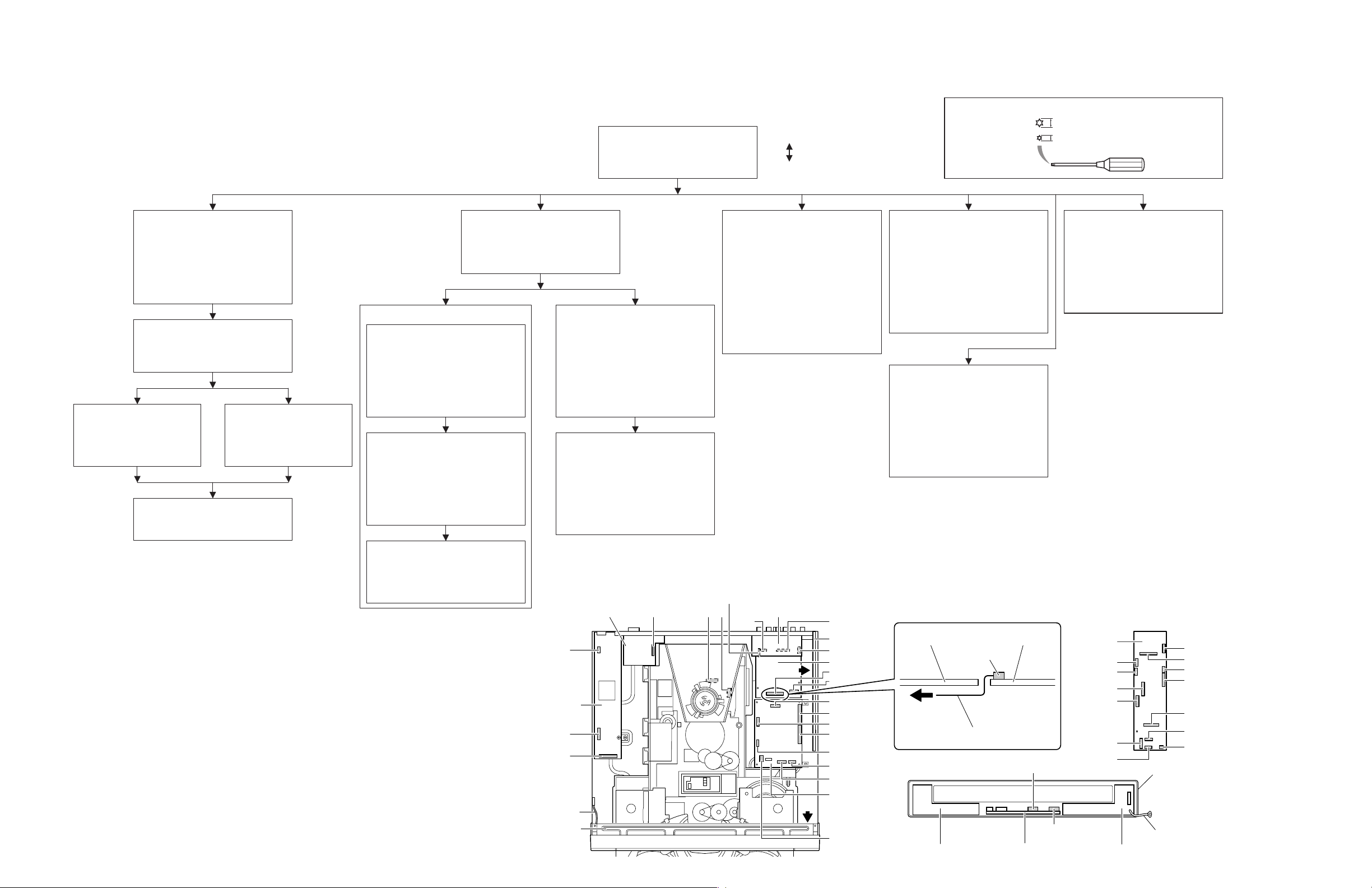
Power supply unit
Front side
RS232C P.C.B.
OK NG
Top view
Switch (Ref. No. 1107)
Potentiometer (Ref. No. VR1)
DivX, DivX Ultra Certified, and associated logos are trademarks of
DivX, Inc. and are used under license.
HDMI, the HDMI logo and High
Definition Multimedia Interface are
trademarks or registered trademarks of HDMI Licensing LLC.
This product incorporates copyright protection technology
that is protected by method claims of certain U.S. patents
and other intellectual property rights owned by Macrovision
Corporation and other rights owners. Use of this copyright
protection technology must be authorized by Macrovision
Corporation, and is intended for home and other limited
viewing uses only unless otherwise authorized by
Macrovision Corporation. Reverse engineering or disassembly is prohibited.
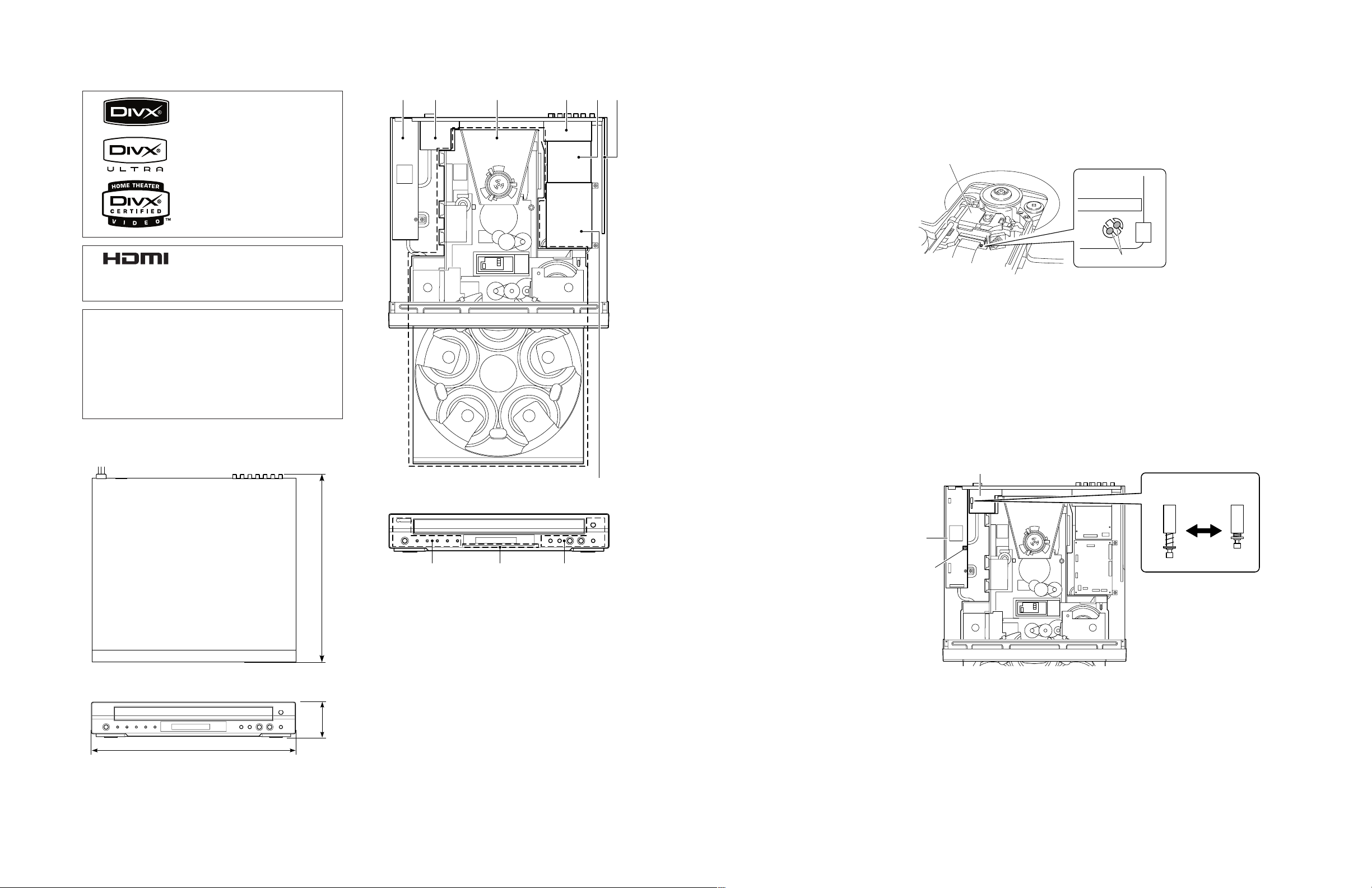
• DIMENSIONS
■ INTERNAL VIEW
1 2 3 4 5 6
■ REPAIR NOTES
1. DVD 5-disc changer module
• When installing a new traverse unit, remove the solder from the shorted point of P.C.B. using an electrostatic
shielding soldering iron. (Fig. 1)
Traverse unit
Solder
Fig. 1
2. Power supply unit
• The power supply unit has to be replaced in case of failure.
• Never touch the potentiometer (Ref. No. VR1) installed to the power supply unit. (Fig. 2)
3. P.C.B. assembly
• When a failure has occurred in the P.C.B. assembly, replace each P.C.B..
• Never touch the switch (Ref. No. 1107) installed to the RS232C P.C.B.. (Fig. 2)
435 (17-1/8")
425 (16-3/4")
75
Unit: mm (inch)
1
POWER SUPPLY UNIT
2
RS232C P.C.B.
3
DVD 5-DISC CHANGER MODULE
4
FRONT (4) P.C.B.
5
HDMI P.C.B.
6
AV P.C.B.
7
MONO P.C.B.
8
(2-15/16")
FRONT (2) P.C.B.
9
FRONT (1) P.C.B.
0
FRONT (3) P.C.B.
7
8 9 0
Fig. 2
7
DVD-C961
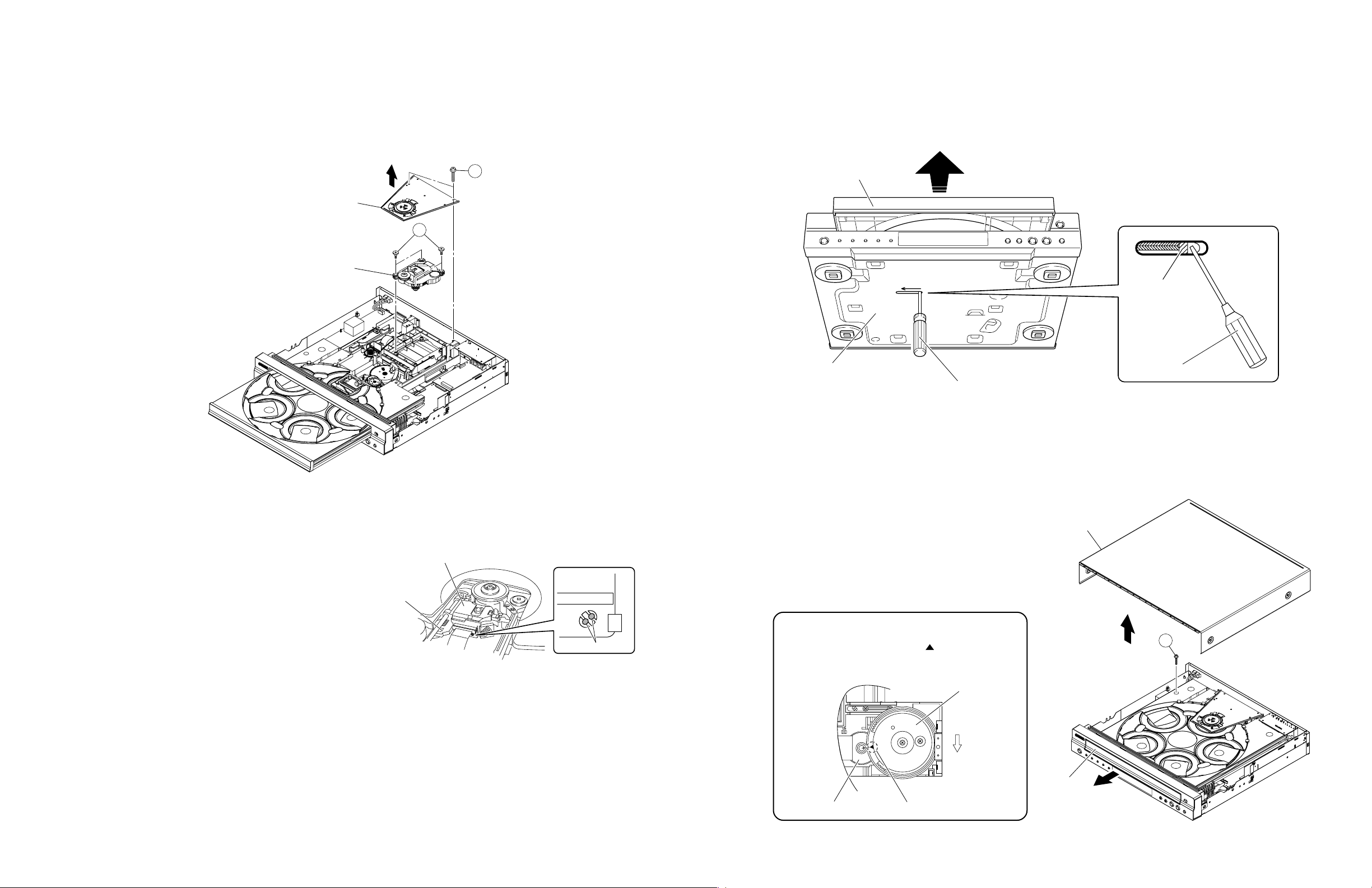
View A
■ DISASSEMBLY PROCEDURES
See replacement parts list for item numbers.
Front Panel Ass'y [101]
➝ Remove 2 screws.
[257] (
➝ Unlock front panel from frame by
➝ Remove 1105, 1109 and ground lead.
Bracket Front
➝ Remove 4 screws. [252]
➝ Remove bracket front.
FRONT (2) P.C.B. [1200]
➝ Remove 1100 (FRONT).
(Fig. 1)
➝ Remove 3 screws. [252]
➝ Remove P.C.B..
FRONT (1) P.C.B. [1200]
➝ Remove 2 screws. [251]
➝ Remove P.C.B..
Bracket front to bottom frame.
releasing successively 4 snaps.
(2 on the side and 2 on the bottom.)
(Fig. 1)
(Bracket front to front panel.)
FRONT (3) P.C.B. [1200]
➝ Remove 1101 (FRONT).
(Fig. 1)
➝ Remove 5 screws. [252]
➝ Remove P.C.B..
When disassembling, use the special screw driver with tip shape in figure.
2.7 mm
T10
Top Cover [240]
➝ Remove 7 screws. [257]
(4 on side and 3 rear side.)
➝
Lift top cover from rear side to remove.
Preventive Measure for Laser Diode
➝ Remove 2 screws (1). (Fig. 2)
)
DVD 5-Disc Changer Module
Tray Ass'y
➝ Remove stopper screw (3). on the
tray. (Fig. 5)
(See "Removal of tray ass'y".)
➝ Open tray. (Fig. 4)
(See "How to manually open the tray
ass'y".)
➝ Gently pull the tray out.
Traverse Unit
➝ Remove 4 screws (2).
(Traverse unit to CM unit.)
*
Use the phillips screwdriver to
remove screws marked (
➝ Remove A and B.
(Fig. 1)
➝ Remove traverse unit.
➝ Remove clamper ass’y. (Fig. 2)
➝ Solder the lands of the optical pick
up. (Fig. 2)
MONO P.C.B. [1300]
➝ Open tray. (Fig. 4)
(See "How to manually open the tray
ass'y".)
➝ Remove 1101 (MONO), 1102 (MONO),
1104 (MONO), 1105, 1301, 1303, 1304
and 1305. (Fig. 1)
➝ Remove 4 screws. [257]
(P.C.B. to bottom frame.)
➝ Remove P.C.B..
HDMI P.C.B. [1800]
➝ Remove 1302, 1401 and 1402. (Fig. 1)
➝ Remove 2 screws. [252]
(P.C.B. to rear panel.)
2
).
➝ Remove screw. [257]
(P.C.B. to rear panel.)
➝ Remove 2 screws. [257]
(P.C.B. to bottom frame.)
➝ Remove P.C.B..
AV P.C.B. [1500]
➝ Open tray. (Fig. 4)
(See "How to manually open the tray
ass'y".)
➝ Remove 1100 (AV), 1101 (AV), 1102
(AV), 1103 (AV), 1104 (AV), 1109,
1200, 1300, 1310, 1400, 1401, 1402
and 1460. (Fig. 1)
➝ Remove screw. [252]
(P.C.B. to rear panel.)
➝ Remove screw. [268 (3 x 4)]
(P.C.B. to bottom frame.)
➝ Remove P.C.B..
Mounting
Dismounting
Power Supply Unit [1000]
➝ Open tray. (Fig. 4)
(See "How to manually open the tray
ass'y".)
➝ Remove CN1, CNA and CNB. (Fig.
1)
➝ Remove 2 screws. [257]
(P.C.B. to bottom frame.)
➝ Release 2 spacers locking.
(P.C.B. to bottom frame.)
➝ Remove power supply unit.
RS232C P.C.B. [1700]
➝ Open tray. (Fig. 4)
(See "How to manually open the tray
ass'y".)
➝ Remove screw. [257]
(P.C.B. to rear panel.)
➝ Remove 2 jack screws.
(P.C.B. to rear panel.)
➝ Remove 1103 (RS232C). (Fig. 1)
➝ Remove P.C.B..
1.7 mm
T6
FRONT (4) P.C.B. [1200]
➝ Open tray. (Fig. 4)
(See "How to manually open the tray
ass'y".)
➝ Remove 5 screws. [252]
(P.C.B. to rear panel.)
➝ Remove 1500 and 1503.
(Fig. 1)
➝ Remove P.C.B..
CM Unit
➝ Remove 1101 (MONO), 1102 (MONO),
1305 and 1460.
➝ Remove 5 screws. [257]
➝ Remove CM unit.
Power supply unit
• Cable Connections
RS232C P.C.B.
CN1
CNA
CNB
1103 (RS232C)
1302 (HDMI)
AB
FRONT (4) P.C.B.
View B
15001503
AV P.C.B.
1401 (HDMI)
HDMI P.C.B.
1000
1402
1303
1301
1101 (MONO)
1304
1102 (MONO)
1105
AV P.C.B.
1000
To 1304
(MONO P.C.B.)
Flexible flat cable (30P 180mm)
• View A
HDMI P.C.B.
1101 (FRONT)
AV P.C.B.
1200
1104 (AV)
1103 (AV)
1401
1100 (AV)
1109
• View B
1102 (AV)
1101 (AV)
1310
1300
1400
1402
1460
Front panel ass'y
1104 (MONO)
MONO P.C.B.
Ground lead
Bracket front
8
View A
1305
Fig. 1
1100 (FRONT)
FRONT (2) P.C.B.FRONT (1) P.C.B.FRONT (3) P.C.B.
Ground lead
DVD-C961
Gear/L0
Front panel
Gear/L01
Marking
• Precaution for installation of the tray ass'y.
On tray ass’y setting.
Check the direction of marking " " on gear according
to this drawing.
b. c.
Top cover
Tray ass'y
a.
3
Tray ass'y
Flatblade screwdriver
Flatblade screwdriver
Bottom side
Slider
• Preventive measure for laser diode from electrostatic breakdown
When replacing the MONO P.C.B. or DVD 5-disc changer module, solder between lands of the optical pick up P.C.B. to
protect the laser diode against electrostatic breakdown.
Use the phillips screwdriver to remove screws (2). (Fig. 2)
*
1
Clamper ass'y
2 *
Traverse unit
• How to manually open the tray ass’y
a. Move the slider in the direction indicated with a flatblade screwdriver until the tray is ejected.
b. Gently pull the tray ass’y out.
Fig. 4
Notes
• Use an anti-static soldering iron to short-circuit and
unshort-circuit laser diode.
• After you have finished repairing, remove the
solder from the short-circuit location.
• When installing a new traverse unit, remove the
solder from the shorted point of P.C.B. using an
electrostatic shielding soldering iron.
Fig. 2
Traverse unit
Optical pick up
• Removal of tray ass’y
* The tray ass’y cannot be supplied independently. The tray ass’y is contained in DVD 5-disc changer module and
supplied as a DVD 5-disc changer module.
a. Remove the top cover.
b. Open tray (see “How to manually open the tray
ass’y”).
c. Remove screw (3).
d. Remove the tray ass’y.
Solder
Fig. 3
Fig. 5
9
ABCDEFGHI J
DVD-C961
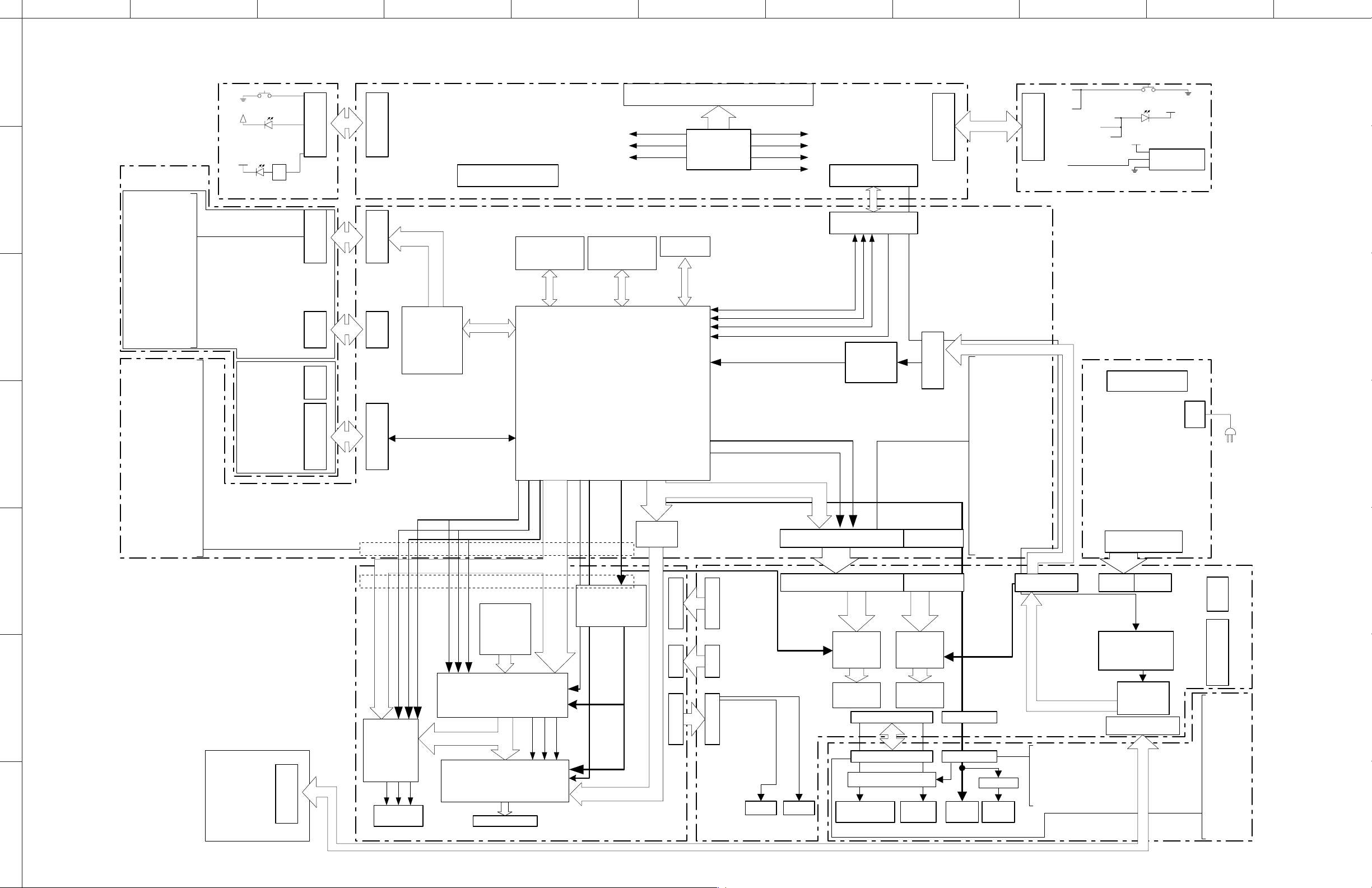
1
■ BLOCK DIAGRAM
Keys
+5V STBY
+5V STBY
DVD 5-DISC
2
3
4
CHANGER MODULE
1
GND
2
LD_DVD
3
NC
4
HFM
5
MD
6
LD_CD
7
VR_DVD
8
VR_CD
9
NC
10
E
11
VCC
12
VC
13
GND
14
F
15
B
(KHM313AAA)
16
A
TRAVERSE UNIT
17
RF
18
CD/DVD
19
D
20
C
21
T-
22
T+
23
F+
24
F-
1
GND
2
SDA
3
SCL
4
GND
5
27M
6
GND
7
YUV(0)
8
GND
9
YUV(1)
10
GND
11
YUV(2)
12
+12VD
13
YUV(3)
14
+5V
15
YUV(4)
16
+3V3
17
YUV(5)
18
+3V3
19
YUV(6)
20
GND
21
YUV(7)
22
GND
23
MCLK
24
GND
25
VSYN
26
GND
27
SPDIF_OUT
28
GND
29
INT
30
HSYN
FRONT (2) P.C.B.
1
2
3
4
5
6
(SD5.5)
CM UNIT
MONO P.C.B.
(SD6.3)
5
6
1
RC_IN
2
IR_SW
3
RESET
4
+5V_STBY
5
SCL
6
SDA
7
GND
7
RS232C P.C.B.
8
STBY_CTRL
B02
DISC1-5_Y
7300
SCL/SDA
SPSP+
LIMIT
GND
SLEDSLED+
12GND
+12V
1
IRQ
2
SCL
3
SDA
4
NC
5
GND
6
+8V
7
+8V
8
GND
1103
8P EH V to AV
1300
12P 1.0 FFC H
to AV_1460
1304
1000
1100
1
B02
GND
2
Disc5_Y
3
Disc4_Y
4
Disc3_Y
5
Disc2_Y
6
Disc1_Y
7
12P 1.0 FFC H8P 1.0 FFC H
+5VL
8
+5V_STBY
9
SDA_uP
10
GND
11
SCL_uP
12
H
24P 0.5 FFC
1101
7111
MOTOR
DRIVER
6P PH V
1102
1305
MM1646XH
I2C
8-bit ITU601
412
50 49 32
Video DAC
ADV7320
37 38 39
7202
Component video
YUV
1003 1002
7100
20-bit YCbCr
7405
IR_SW
RC6_IN
RESET
+5VL
123456789
10P 1.0 FFC V to AV
1112
to AV_1109
27M
HSYNC
VSYNC
30P 1.0 FFC H
30P 1.0 FFC H
7101
SDRAM
MT48LC2M32
Faroudja
FLi2310L
HDMI Tx
Sil9030CTU-7
HDMI OUT
GND
-24V
+12VL
7302
DDR SDRAM
4M x 16
7112
125 119 118
P_VSYNC
P_CLK
66
21
+5V_STBY
STBY_CTRL
10
8-bit ITU601
47
P_HSYNC
42
7100
STDBY_CTRL
DISC1Y_5Y
FRONT (1) P.C.B.
7303 7301
Flash
2M x 8
MT1389B
I2C
Buffer
74LVC125
IO
Expander
PCF8574T
7201
Video Reset
HDMI Reset
I2C
SPDIF/I2S
HDMI P.C.B. AV P.C.B. FRONT (4) P.C.B.
RESET
10
21
Microprocessor
2-6
7101
E2PROM
I2C
11P 1.0 FFC V13P 1.0 FFC V 7P PH H
1305
1402
1302
VFD
111
102
103
104
I2S_0_1_2_3
11P 1.0 FFC V13P 1.0 FFC V 7P PH H
1104
10
11
1401
1102
10
11
12
13
1101
22
R6C_OUT
23
24
26-28
SCL
SDA
B01-03
VINTRQ
SDA
SCL
GND
RC6_OUT
123456789
9P 1.0 FFC V
1110
9P 1.0 FFC V
1105
RC6
Front_I2C_DAT
Front_I2C_CLK
Front_I2C_IRQ#
3.3V
S0
S1
Regulator
STDBY_CTRL
1104
SPDIF
1
GND
2
PCM_MCLK
3
GND
4
SD3
5
SD2
6
SD1
7
SD0
8
GND
9
PCM_LRCLK
PCM_SCLK
GND
1301
1101
30P 1.0 FFC H
30P 1.0 FFC V
I2S_1
7200
6-Ch DAC
CS4360
7300
_2_3
1303
12P 1.0 FFC V
1200
12P 1.0 FFC V
I2S
7201
2-Ch DAC
AK4385
7300
_0
Pre-AMP Pre-AMP
1
GND
2
DPDET
3
DLINE3
4
DLINE2
5
DLINE1
6
+5VID
7
GND
8
CVBS
9
GND
C
GND
Y
GND
S-Video CVBS
1107 1107
1300
22P 1.0 FFC V 9P 1.0 FFC V
1500
22P 1.0 FFC V 9P 1.0 FFC V
7502-7516
Mute circuit
1502
5.1 CH
Analog audio
1501 7600 1600
MIXED 2CH
L/R
VIDEO OUT AUDIO OUT DIGITAL OUT
10P 1.0 FFC H
1
2
3
16P 1.0 FFC V
4
5
6
7
8
9
10
11
12
13
14
15
16
17
18
19
20
21
22
23
24
25
26
27
28
29
30
1
GND
2
PCM_LR
3
GND
4
PCM_LsRs
5
GND
6
PCM_Clfe
7
GND
8
PCM_Cs
9
GND
10
SCL
11
SDA
12
RESET
MUTE/SPDIF
MUTE
OPTICAL COAXIAL
1200
GND
P50
NC/L2
SCART1/L3
SCART2/L3
AV_MUTE
VGND
Y
VGND
C
VGND
CVBS
VGND
G_Y
VGND
B_U
VGND
R_V
GND
PCMSCLK
PCMDATA_L0
GND
PCMCLK
PCMLRCLK
GND
SPDIF_OUT
GND
SPDIF_PCM_Data_IN
GND
MIC_DET
16P 1.0 FFC H
SPI
1310
1503
5601
Buffer
B01
1
GND
2
B03
3
LED_Progressiv
4
LED_HDMI
5
LED_Downmix
6
+5VL
7
10P 1.0 FFC H
+5V_STBY
8
IR
9
GND
10
1100
1
GND
2
GND
3
+1V8 _senses
4
+1V8
5
+1V8
6
+5VL
7
+5VL
8
+5VL
9
GND
10
+8V
11
GND
12
STDBY_CTRL
13
DAC_STB
14
SCL
15
SDA
16
GND
1
MUTE_SLR
2
MUTE_LFE_CE
3
MUTE
4
MUTE_TVLR
5
GND
6
MUTE_FLR
7
SPDIF_OUT
8
GND
9
+5VD
Keys
+5VL
+5V STBY
7102
IR
FRONT (3) P.C.B.
CN3
to AV_1402
5PEH V to AV
12345
GND
+5VL
+12VL
+5V_STBY
CN4
-24V
POWER SUPPLY UNIT
+5V_XM
GND
+5VL
+5VL
GND
+12VL
GND
-12VL
STBY_CTRL
POWER_DN
+12VL
GND
+5V_STBY
12345678910111213
CN1
1111
13P PH V
1400
13P PH 5P EH V
STDBY_CTRL
1
2
3
4
5
Power Switching
Circuit
Regulator
8P EH V to RS232C
1402
+5VL
+12VL
GND
+5V_STBY
-24V
SUPPLY
UNIT_CN3
to POWER
1460
1109
1
2
3
4
5
6
7
8
9
10
11
12
13
14
15
16
17
18
19
20
21
22
AC IN
to SD5.5
2P PH V
to DVD 5-DISC
to FRONT (1)
10P 1.0 FFC V
to FRONT (1)_1112
RT
GND
GND
GND
LT
GND
SURR_R
GND
GND
GND
SURR_L
GND
LEF
GND
GND
GND
CE
GND
FR
GND
GND
FL
MODULE
CHANGER
10
ABCDEFGH I J
1
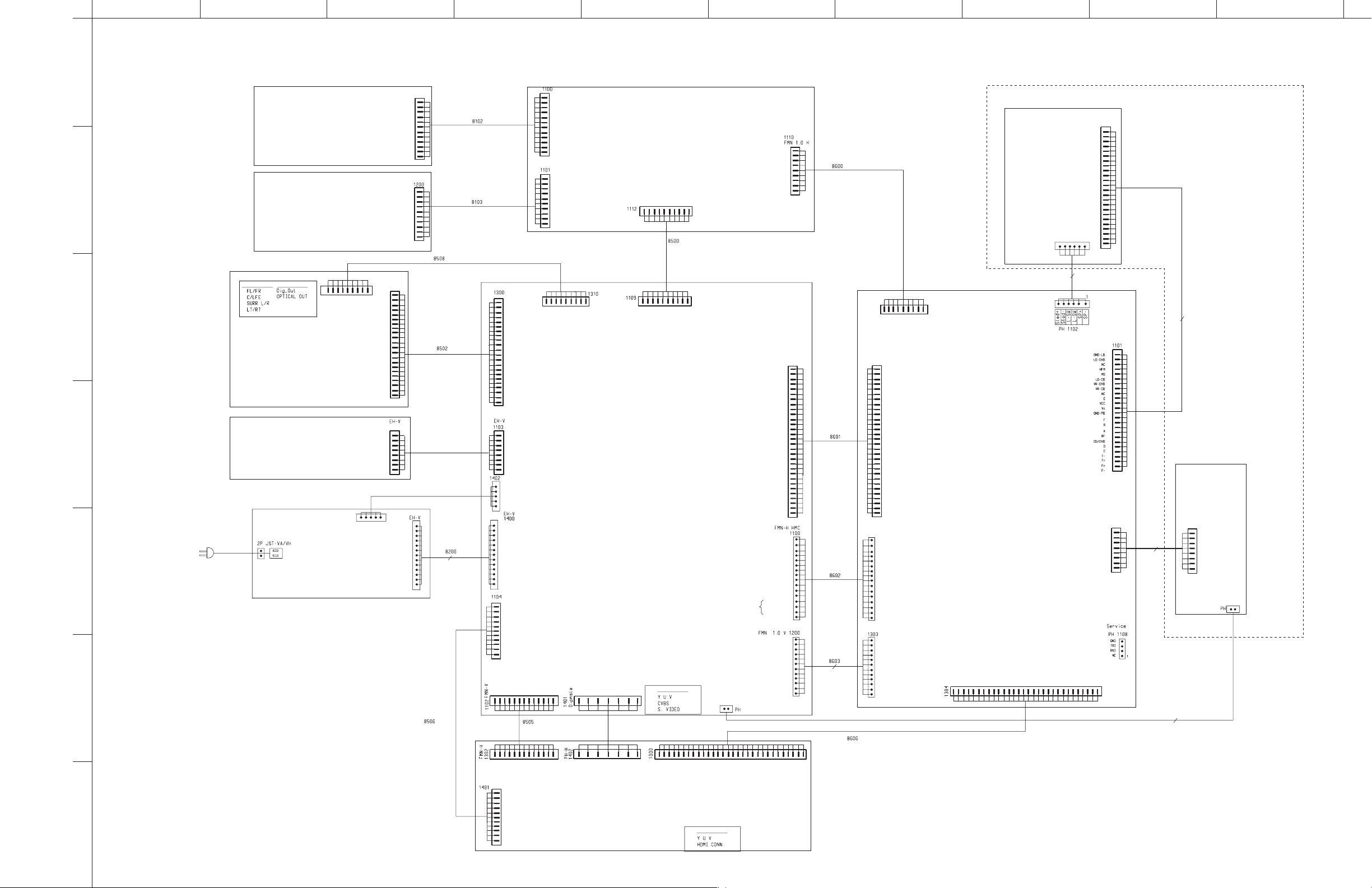
■ WIRING DIAGRAM
2
FMN 1.0 H
1300
I2C_CLK
12
GND_D
11
I2C_DATA
10
+5VSTDBY
9
8
+5VL
7
FRONT (2) P.C.B. FRONT (1) P.C.B.
FRONT (3) P.C.B.
DISC1_Y
DISC2_Y
DISC3_Y
DISC4_Y
DISC5_Y
GND_B
KEY_B02
KEY_B01
GND_B
KEY_B03
LED_PROGRESSIVE
LED_HDMI
LED_DOWNMIX
+5VL
+5VSTBY
GND_D
6
5
4
3
2
1
FMN SM 1.0 H
1
2
3
4
5
6
7
8
9
IR
10
12P, 280mm
10P, 340mm
FMN 1.0 H
FMN SM 1.0 H
I2C_CLK (from MCU)
12
11
GND_D
10
I2C_DATA (from MCU)
+5VSTDBY
9
+5VL
8
DISC1_Y
7
DISC2_Y
6
DISC3_Y
5
DISC4_Y
4
DISC5_Y
3
GND_B
2
KEY_B02
1
10
KEY_B01
9
GND_B
8
KEY_B03
LED_PROGRESSIVE
7
6
LED_HDMI
LED_DOWNMIX
5
4
+5VL
3
+5VSTBY
2
IR (from IR eye)
GND_D
1
FMN SM 1.0 H
+5Vstdby
STDBY_CTRL
+12VL
10
9
876
+5VL
-24V
GND_D
5
RC6_IN (from RS232 board)
IR_SW (from RS232)
RESET
mute_uP
1
432
10P, 560mm
INTRQ
I2C_DATA
I2C_CLK
GND_D
1KHZ ( not used )
RC6_OUT
STDBY_CTRL
GND_D
DVD-C961
DVD 5-DISC CHANGER MODULE
TRAVERSE UNIT
KHM313
1
2
3
4
5
6
7
8
NC
9
9P, 340mm
1109
1
2
3
4
5
6
7
8
9
10
11
12
13
14
15
16
17
18
19
20
21
22
23
24
-12VL
9P, 180mm
FMN-22-V
1
RT
2
GND
3
GND
4
GND
LT
5
GND
6
SURR_R
7
GND
8
9
GND
GND
10
SURR_L
11
12
1
2
3
4
5
1
2
3
4
5
6
7
8
9
10
11
12
13
GND_D
DPDDETN
2
13
14
15
16
17
18
19
20
21
22
1
2
3
4
5
6
7
8
+5VL
+12VL
GND
+5Vstby
-24V
+5V_XM
GND
+5V_VL
+5V_VL
GND
+12VL
GND
-12VL
STBY_CTRL
Power_DN
+12VL
GND
+5V_STBY
1
GND
SCLK
2
LRCLK
3
4
GND
LR_PCM
5
6
SLR_PCM
7
SubCen_PCM
8
Cs_PCM
9
GND
MCLK
10
11
GND
DLINE2
DLINE3
4
3
GND
LFE
GND
GND
GND
CE
GND
FR
GND
GND
FL
RC6_IN
RC6_OUT
RESET
+5VStdby
I2C_CLK
I2C_DATA
GND
STDBY_CTRL
V_GND
DLINE1
+5VA
5
6
7
22P, 180mm
8P, 480mm
5P, 560mm
CN1
1
GND
2
3
4
GND
5
6
7
GND
8
13P, 560mm
9
10
11
GND
12
13
V/CVBS
V_GND
8
9
U/C1Y
10
1
2
MUTE_SLR
MUTE_LFE_CE
V_GND
11
12
3
MUTE
V_GND
456
GND
MUTE_FLR
MUTE_TVLR
7
SPDIF_OUT
FMN SM 1.0 H
8
9
GND
+5VD
AV P.C.B. MONO P.C.B.
1102
3
+12VL
+5Vstdby
STDBY_CTRL
4
567
8
9
-24V
+5VL
IR_SW
GND_D
RESET
RC6_IN
mute_uP
FMN 1.0 V
1101
1
GND
P50
2
NC / Line 2
3
SCART1/Line3
4
5
SCART0/Line3
6
AV_MUTE
7
Y_REF
Y
8
9
C_REF
10
C
11
CVBS_REF
CVBS
12
G_REF
13
G_Y
14
B_REF
15
B_U
R_REF
PCMSCLK
PCMDATA_LO
PCMCLK
PCMLRCLK
SPDIF_out
SPDIF_PCM_Data_MIC_IN
Mic_det
+1V8_Sense
STDBY_CTRL
DAC_STDBY
To control
SCL-DAC
DAC
SDA-DAC
AK4382A
16
17
R_V
18
GND
19
20
21
GND
22
23
24
25
GND
26
GND
27
28
GND
29
30
GND
GND
+1V8
+1V8
+5VL
+5VL
+5VL
GND
+8V
GND
GND
30P, 180mm
16
15
14
13
12
11
10
9
8
16P, 140mm
7
6
5
4
3
2
1
7
8
9
STDBY_CTRL
VolB ( not used )
VolA ( not used )
SFW30R-2STE 1
1301
1
GND
P50
2
NC / Line 2
3
SCART1/Line3
4
SCART0/Line3
5
6
AV_MUTE
Y_REF
7
8
Y
C_REF
9
10
C
11
CVBS_REF
CVBS
12
G_REF
13
G_Y
14
B_REF
15
B_U
16
17
R_REF
R_V
18
GND
19
20
PCMSCLK
PCMDATA_LO
21
GND
22
PCMCLK
23
24
PCMLRCLK
GND
25
26
SPDIF_out
27
GND
28
SPDIF_PCM_Data_MIC_IN
GND
29
Mic_det
30
FMN-V SM
1104
GND
1
2
GND
3
+8V
+1V8
4
+1V8
5
6
+5VL
+5VL
7
+5VL
8
9
GND
+8V
10
11
GND
12
STDBY_CTRL
13
Strobe
VSCK
14
VSDA
15
16
GND
6
RC6_OUT (front)
SFW12S-2STE 1
1
+5VL
1
CEC
2
GND_D
3
+3V3
4
GND_D
5
+3V3
6
Interface connections
+12V_Power
Video Signal
7
GND
+12V
1
2
PCM_Data_LR
PCM_Data_sLR
PCM_Data_Sub/Cen
PCM_Data_EX_sLR (op)
I2C_CLK
I2C_DATA
DAC_RST
1460
GND
2
3
GND
4
GND
5
6
7
GND
GND
12P, 180mm
8
9
10
11
12
1
GND
2
PCM_Data_LR
3
GND
4
PCM_Data_sLR
GND
5
6
PCM_Data_Sub/Cen
7
GND
8
PCM_Data_EX_sLR (op)
9
GND
10
I2C_CLK
11
I2C_DATA
12
DAC_RST
432
5
1KHZ ( not used )
GND_D
I2C_CLK
I2C_DATA
1
INTRQ
1105
FMN 1.0 V
SFW30R-2STE 1
(SD 6.3)
I2C_DATA
GND
27M
I2C_CLK
GND
1
4
3
5
GND
6
VDATA0
789
GND
GND
VDATA1
10
VDATA2
11
GND
12
VDATA3
NC
13
14
VDATA4
NC
15
161718
NC
VDATA5
Interface connection
Audio Signal Dig Aud Sig
3
FRONT (4) P.C.B.
1503
7
8
9
MUTE
MUTE_SLR
MUTE_LFE_CE
6
GND
MUTE_FLR
MUTE_TVLR
12345
GND
+5VD
SPDIF_OUT
SURR_R
SURR_L
FMN-22-V
RT
GND
GND
GND
LT
GND
GND
GND
GND
GND
LFE
GND
GND
GND
CE
GND
FR
GND
GND
FL
1500
22
21
20
19
18
17
16
15
14
13
12
11
10
9
8
7
6
5
4
3
2
1
1103
1
RC6_IN
2
CN3
RC6_OUT
RESET
+5VStdby
I2C_CLK
I2C_DATA
STDBY_CTRL
1
2
345
GND
+5VL
+12VL
GND
+5Vstby
-24V
3
4
5
6
7
8
+5V_XM
+5V_VL
+5V_VL
+12VL
STBY_CTRL
Power_DN
+12VL
+5V_STBY
4
5
RS232C P.C.B.
CN4
POWER SUPPLY UNIT
6
11P, 100mm 13P, 220mm 7P, 80mm
VDATA6
19220
GND
VDATA7
21
6P
24P
SFW24R-2STE 1
1
2
3
4
5
6
7
8
9
10
11
12
13
14
15
16
17
18
19
20
21
22
23
24
CM UNIT
1305
SFW8R-2STE 1
1
IRQ
2
SCL
3
SDA
NC
4
5
GND
6
NC
NC
7
GND
8
GND
NC
GND
SPDIFOUT
HDMI_IRQ
NC
NC30GND
GND
27
28
29
25
26
24
23
22
30
8P
(SD 5.5)
2P
1
IRQ
2
SCL
3
SDA
NC
4
5
GND
NC
6
NC
7
GND
8
GND
+12V
1
2
30P, 180mm
5
6
4
3
DLINE3
DLINE2
DPDDETN
1
GND
SCLK
2
LRCLK
3
GND
4
LR_PCM
5
SLR_PCM
6
SubCen_PCM
7
Cs_PCM
8
GND
9
MCLK
10
GND
11
DLINE1
+5VA
7
8
V/CVBS
AV_GND
9
10
U/C
AV_GND
111213
Y
AV_GND
2
CEC
3
GND_D
4
+3V3
5
GND_D
+3V3
1
+5VL
AV_GND 13
7
6
1
+12V_Power
HDMI P.C.B.
Interface connection
Video Signal
1
2
GND_D
7
11
DVD-C961
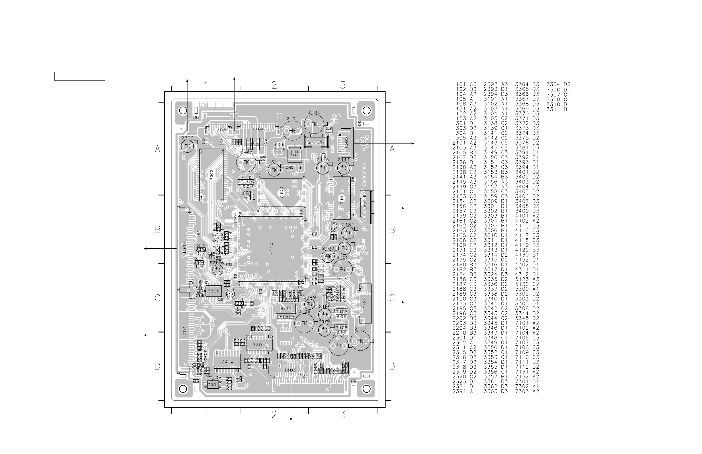
■ PRINTED CIRCUIT BOARDS
FOR INFORMATION ONLY (NO REPLACEMENT COMPONENT PARTS WILL BE AVAILABLE)
AV
MONO P.C.B.
(Top view)
FRONT (1)
(1110)
(1100)
The first digit of a component indicates the component type.
1xxx : Connector 3xxx : Resistor 5xxx : Coil 7xxx : IC, Transistor, FET
2xxx : Capacitor 4xxx : SMD jumper 6xxx : Diode 9xxx : Wire jumper
(1000)
HDMI
(1101)
AV
DVD 5-DISC CHANGER MODULE
KHM313
TRAVERSE UNIT
KHM313
TRAVERSE UNIT
12
AV
(1200)
MONO P.C.B.
(Bottom view)
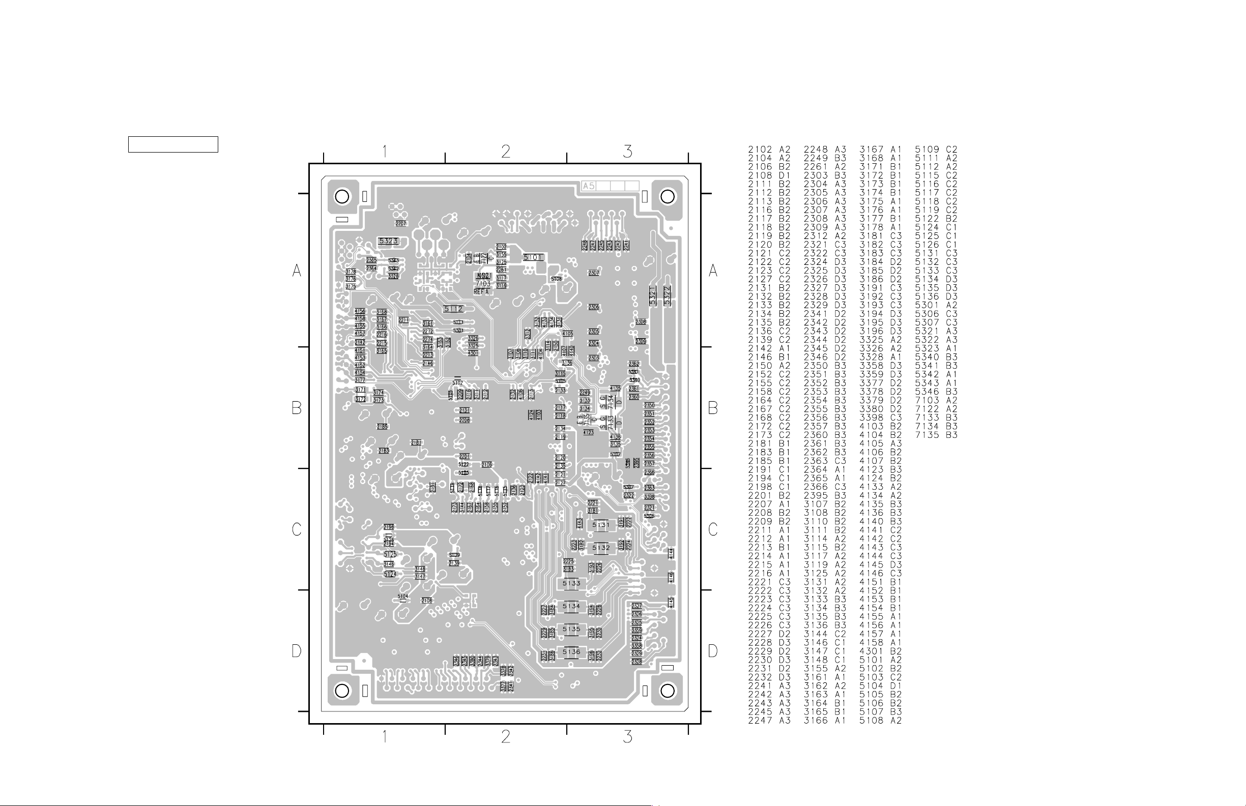
DVD-C961
The first digit of a component indicates the component type.
1xxx : Connector 3xxx : Resistor 5xxx : Coil 7xxx : IC, Transistor, FET
2xxx : Capacitor 4xxx : SMD jumper 6xxx : Diode 9xxx : Wire jumper
13
 Loading...