

~YAMAHA
f).
sr
"'
OWNER'S
MANUAL
38
K-28199-
71
A-604
IDENTIFICATION
NUMBERS
RECORD
1. KEY
NUMBER:
2. VEHICLE
NUMBER:
3.
ENGINE
NUMBER:
Your key identification number
is
stamped
on your key
as
shown
in the
following
illus-
tration.
Record this number
in
the space provided
for
reference if you need a
new
key.
Key number
Record your vehicle and engine numbers in
the spaces provided
to
assist you
in
ordering
spare parts from your
Yamaha dealer or for
reference in case your
vehicle
is
stolen. (See
page
3-1)
DT50W
OWNER'S
MANUAL
©1988
by
Yamaha
Motor
Co., Ltd.
1st
Edition,
June
1988
All
rights
reserved.
Any
reprinting
or
unauthorized
use
without
the
written
permission
of
yamaha
Motor
Co., Ltd.
is
expressly
prohibited.
Printed
in
Japan
A-200
INTRODUCTION
Congratulations on your purchase
of
the
Yamaha DT50W. This
model
is
the result
of
Yamaha's vast experience
in
the production
of
fine sporting, touring, and pacesetting
racing machines.
It
represents the high degree
of
craftsmanship and reliability that have
made Yamaha a
leader
in
these fields.
This manual
will
give you
an
understanding
of
the operation, inspection, and basic
maintenance
of
this motorcycle.
If
you have
any questions
about
the operation or main-
tenance
of
your motorcycle, please consult
a Yamaha dealer.
U-001
NOTE:~~~~~~~~~~~~
Some data
in
this manual may become
out-
dated due
to
future improvement on this
model.
If
you have any questions about this
manual or your motorcycle, please consult a
Yamaha
dealer.
TECHNICAL
PUBLICATIONS
SERVICE
DIVISION
MOTORCYCLE
GROUP.
YAMAHA
MOTOR
CO
..
LTD.
A-101
U-601
&WARNING:
PLEASE READ THIS
MANUAL
CARE-
FULLY
AND
COMPLETELY
BEFORE
OPERATING
THIS
MOTORCYCLE.
Particularly important information is distin-
guished
in
this manual by the
following
no-
tations:
NOTE:
A NOTE provides key information
to
make
procedures easier or
clearer.
A CAUTION indicates special procedures that
must
be
followed
to
avoid damage to the
motorcycle.
&WARNING:
A
WARNING
indicates special procedures
that must be followed to avoid injury
to
a
motorcycle operator or person inspecting or
repairing the
motorcycle.
U-000
NOTE:~~~~~~~~~~~~
This manual should
be
considered a perma-
nent part of this
motorcycle and should re-
main
with
it
even if the motorcycle is subse-
quently sold.

U-754
LI':,
TIPS FOR SAFETY
TWO-WHEELED
MOTORCYCLES
ARE
SINGLE
TRACK
VEHICLES.
THEIR
SAFE
USE
AND
OPERATION
ARE
DEPENDENT
UPON
THE
USE
OF
PROPER
RIDING
TECHNIQUES
AS
WELL
AS
THE
EXPERTISE OF
THE
OPERATOR.
EVERY
OPERATOR
SHOULD
KNOW
THE
FOLLOWING
REQUIREMENTS
BE-
FORE
RIDING.
HE OR SHE
SHOULD:
1.
OBTAIN
THOROUGH
INSTRUCTIONS
FROM
A
COMPETENT
SOURCE
ON
ALL
ASPECTS
OF
MOTORCYCLE
OPERATION.
2.
OBSERVE
THE
WARNINGS
AND
MAINTENANCE
REQUIREMENTS
IN
THE
OWNER'S
MANUAL.
3.
OBTAIN
QUALIFIED
TRAINING
IN
SAFE
AND
PROPER
RIDING
TECHNIQUES.
4.
OBTAIN
PROFESSIONAL
TECHNICAL
SERVICE
AS
INDICATED
BY
THE
OWNER'S
MANUAL
AND/OR
WHEN
MADE
NECESSARY
BY
MECHANICAL
CONDITIONS.
,
______
---
SAFE
RIDING
1.
Always
make
pre-operation
checks.
Careful
checks
may
help
prevent
an
ac-
cident.
2.
This
motorcycle
is
designed
to
carry
the
operator
only
No
passengers.
3.
The
failure
of
motorists
to
detect
and
recognize
motorcycles
in
traffic
is
the
predominating
cause
of
automobile/motorcycle
accidents.
Many
accidents
have
been
caused
by
an
automobile
driver
who
did
not
see
the
mtorcycle.
Making
yourself
conspicuous
appears
to
be
very
effective
in
reducing
the
chance
of
this
type
of
accident.
Therefore:
a.
Wear a brightly
colored
jacket.
b.
Use
extra
caution
when
you
approach
and
pass
through
intersections,
since
intersections
are
the
most
likely
places
for
motorcycle
accidents.
c.
Ride
where
other
motorists
can
see
you.
Avoid
riding
in
another
motorist's
"blind
spot."
4.
Many
accidents
involve
inexperienced
operators.
In
fact,
many
operators
who
have
been
involved
in
accidents
do
not
even
have a current
motorcycle
license.
a.
Make
sure
you
are
qualified.
Also,
only
lend
your
motorcycle
to
experi-
enced
operators.
b.
Know
your
skills
and
limits.
Staying
within
your
limits
may
help
you
to
avoid
an
accident.
c.
We
recommend
that
you
practice
riding
your
motorcycle
where
there
is
no
traffic
until
you
have
become
thoroughly
familiar
with
your
motorcycle
and
all
of
its
controls.
5.
Many
motorcycle
accidents
have
been
caused
by
motorcycle
operator
errors.
A
typical
error
made
by
the
operator
is
veering
wide
on a turn
due
to
EX-
CESSIVE
SPEED
or
undercornering
(insufficient
lean
angle
for
the
speed).
a.
Always
obey
the
speed
limits
and
never
travel
faster
than
warranted
by
road
and
traffic
conditions.
b.
Always
signal
before
turning
or
changing
lanes.
Make
sure
other
motorists
see
you.
6.
Operator's
posture
is
important
for
proper
control.
The
operator
should
keep
both
hands
on
the
handlebars
and
both
feet
on
the
operator
footrests
during
operation
to
maintian
control
of
the
motorcycle.
7.
Never
ride
under
the
influence
of
alcohol
or
drugs.
PROTECTIVE
APPAREL
The
majority
of
fatalities
from
motorcycle
accidents
are
the
result
of
head
in-
juries.
The
use
of a safety
helmet
is
the
single
most
critical
factor
in
the
pre-
vention
or
reduction
of
head
injuries.
-
---
-------
-------
---
1.
Always
wear
an
approved
helmet.
2.
Wear a face
shield
or
goggles.
Wind
on
your
unprotected
eyes
could
con-
tribute
to
an
impairment
of
vision
which
could
delay
seeing a hazard.
3.
The
use
of
heavy
boots,
jacket,
trousers,
gloves,
etc.
is
effective
in
preventing
or
reducing
abrations
or
lacerations.
4.
Never
wear
loose
fitting
clothing.
It
could
catch
on
the
control
levers,
footrests,
or
wheels
and
cause
injury
or
accident.
5.
Never
touch
the
engine
or
exhaust
system
during
or
after
operation.
They
become
very
hot
and
can
cause
burns.
Always
wear
protective
clothings
that
covers
your
legs,
ankles,
and
feet.
MODIFICATION
Modifications
made
to
the
motorcycle
not
approved
by
Yamaha,
or
the
removal
of
original
equipment,
may
render
your
motorcycle
unsafe
for
use
and
may
cause
severe
personal
injury.
Modifications
may
also
make
your
motorcycle
illegal
to
use.
LOADING
AND
ACCESSORIES
Adding
accessories
or
cargo
to
your
motorcycle
can
adversely
affect
stability
and
handling
if
the
weight
distribution
of
the
machine
is
changed.
To
avoid
the
possibility
of
an
accident,
extreme
caution
should
be
used
if
adding
cargo
or
accessories
to
your
motorcycle.
Use
extra
care
if
riding a motorcycle
which
has
added
cargo
or
accessories.
Here
are
some
general
guidelines
to
follow
if
loading
cargo
or
adding
accessories
to
your
motorcycle:
LOADING
The
total
weight
of
the
operator,
accessories
and
cargo
must
not
exceed
the
maximum
load
limit
of
157
lbs.
(71
kg).
When
loading
within
these
weight
limits,
keep
the
following
in
mind:
1.
Cargo
and
accessory
weight
should
be
kept
as
low
and
close
to
the
motorcycle
as
possible.
Be
sure
to
distribute
the
weight
as
evenly
as
possible
on
both
sides
of
the
machine
to
minimize
imbalance
or
instability.
2.
Shifting
weights
can
create a sudden
imbalance.
Make
sure
that
accessories
and
cargo
are
securely
attached
to
the
motorcycle
before
riding.
Recheck
accessory
mounts
and
cargo
restraints
frequently.
3.
Never
attach
any
large
or
heavy
items
to
the
handlebars,
front
forks,
or
front
fender.
These
items,
including
such
cargo
as
sleeping
bags,
duffle
bags,
or
tents,
can
create
unstable
handling
or
slow
steering
response.
ACCESSORIES
Genuine
Yamaha
accessories
have
been
specifically
designed
for
use
on
this
motorcycle.
Since
Yamaha
cannot
test
all
other
accessories
which
may
be
available,
you
must
personally
be
responsible
for
the
proper
selection,
instal-
lation
and
use
of
non-Yamaha
accessories.
You
should
use
extreme
caution
when
selecting
and
installing
any
accessories.
Keep
in
mind
these
guidelines
for
mounting
accessories
in
addition
to
those
provided
under
"LOADING''.
1.
Never
install
accessories
or
carry
cargo
that
would
impair
the
performance
of
your
motorcycle.
Carefully
inspect
the
accessory
before
using
it
to
make
sure
it
does
not
in
any
way
reduce
ground
clearance
or
cornering
clearance,
limit
suspension
travel,
steering
travel
or
control
operation,
or
obscure
lights
or
reflectors.
a.
Accessories
fitted
to
the
handlebar
or
the
front
fork
area
can
create
in-
stability
due
to
improper
weight
distribution
or
aerodynamic
changes.
If
accessories
are
added
to
the
handlebar
or
front
fork
area,
they
must
be
as
light
weight
as
possible
and
should
be
kept
to a minimum.
b.
Bulky
or
large
accessories
may
seriously
affect
the
stability
of
the
mo-
torcycle
due
to
aerodynamic
effects.
Wind
may
attempt
to
lift
the
mo-
torcycle,
or
the
motorcycle
may
become
unstable
in
cross
winds.
These
accessories
may
also
cause
instability
when
being
passed
by
or
passing
large
vehicle.
c.
Certain
accessories
can
displace
the
operator
from
his
or
her
normal
riding
position.
This
improper
position
limits
the
freedom
of
movement
of
the
operator
and
may
limit
control
ability.
Therefore
such
accessories
are
not
recommended.
2.
Caution
must
be
used
if
adding
electrical
accessories.
If
these
accessories
exceed
the
capacity
of
motorcycle's
electrical
system,
an
electric
failure
could
result,
which
could
cause a dangerous
loss
of
lights
or
engine
power.
GASOLINE
AND
EXHAUST GAS
1. GASOLINE IS HIGHLY
FLAMMABLE:
a.
Always
turn
off
the
engine
when
refueling.
b.
Take
care
not
to
spill
any
gasoline
on
the
engine
or
exhaust
pipe(s)/muffler(s)
when
refueling.
c.
Never
refuel
while
smoking
or
in
the
vicinity
of
an
open
flame.
2.
Never
start
the
engine
or
let
it
run
for
any
length
of
time
in a closed
area.
The
exhaust
fumes
are
poisonous
and
may
cause
loss
of
consciousness
and
death
within
a
short
time.
Always
operate
your
motorycle
in
an
area
that
has
adequate
ventilation.
3.
Always
turn
off
the
engine
before
leaving
the
motorcycle
unattended
and
remove
the
ignition
key.
When
parking
the
motorcycle,
note
the
following:
a.
The
engine
and
exhaust
pipe(s)/muffler(s)
may
be
hot.
Park
the
motorcycle
in a place
where
pedestrians
or
children
are
not
likely
to
touch
these
hot
areas.
b.
Do
not
park
the
motorcycle
on a slope
or
soft
ground:
the
motorcycle
may
fall
over.
c.
Do
not
park
the
motorcycle
near
an
flammable
source,
e.g. a kerosene
heater,
or
near
an
open
flame.
The
motorcycle
could
catch
fire.
4.
When
transporting
the
motorcycle
in
another
vehicle,
be
sure
it
is
kept
upright
and
that
the
fuel
cock(s)
is
turned
to
"ON"
or
"RES"
(for
vacuum
type)/"OFF"
(for
manual
type).
If
it
should
lean
over,
gasoline
may
leak
out
of
the
car-
buretor
or
fuel
tank.
5.
If
you
should
swallow
any
gasoline,
inhale a lot
of
gasoline
vapor,
or
allow
gasoline
to
get
in
your
eye(s),
see
your
doctor
immediately.
If
any
gasoline
spills
on
your
skin
or
clothing,
immediately
wash
with
soap
and
water
and
change
your
clothes.

A-305
CONTENTS
LOCATION
OF
THE
Rear
brake pedal................................. 4-7
IMPORTANT LABELS ......................... . 1
-1
Fuel
cock ............................................ 4-7
Starter knob
(CHOKE) .......................
4-8
DESCRIPTION ....................................... 2-1 Kick starter ..........................................
4-8
Steering lock .......................................
4-9
MOTORCYCLE IDENTIFICATION ....... 3-1 Helmet holder ........ .......... ............ .......
4-9
Vehicle identification number ............. 3-1 Note handling
of
the Yamaha
Engine serial number .......................... 3-1 Energy Induction system ..................
4-10
Sidestand .......................................... 4-11
CONTROL FUNCTIONS ....................... 4-1
Sidestand switch operation check
...
4-11
Main switch
..
.......... ......
..
...... .............. 4-1
Indicator lights ....................................
4-2
PRE-OPERATION CHECKS .................. 5-1
Oil warning light checking method ....
4-3
Brakes .................................................
5-3
Speedometer.......................................
4-4
Clutch .................................................
5-3
Tachometer .........................................
4-4
Throttle grip ........................................
5-3
Engine temperature gauge .................
4-4
Engine oil ............................................
5-3
Handlebar switches ............................
4-5
Transmission oil ..................................
5-4
Clutch lever .........................................
4-6
Coolant ...............................................
5-5
Change pedal......................................
4-6
Chain ...................................................
5-6
Front brake lever ................................. 4-7
Tires ....................................................
5-6
Wheels ................................................
5-8
Transmission oil replacement ............. 7 -7
Fittings/Fasteners ...............................
5-9
Cooling system.................................
7-8
Lights and signals ...............................
5-9
Fuel cock cleaning ............................ 7-11
Switches
.. .. .. . ..
......
....
...
.. . .. ..
...
.. . ..
...
..
...
5-9
Air filter ............................................. 7-11
Battery .................................................
5-9
Carburetor adjustment ......................
7-13
Fuel .....................................................
5-9
Idle speed adjustment .......................
7-13
Throttle cable adjustment .................
7-14
OPERATION
AND
IMPORTANT
Spark plug inspection....................... 7 -15
RIDING POINTS ................................... 6-1 Front brake adjustment .....................
7-16
Starting a cold engine ........................ 6-1
Rear
brake adjustment.. ....................
7-17
Engine
warm-up
.................................
6-3
Brake light switch adjustment ..........
7-18
Starting a warm engine ......................
6-3
Checking the brake shoes ................
7-19
Shifting ...............................................
6-3
Clutch adjustment ............................ 7 -19
Engine break-in ..................................
6-4
Mechanism adjustment ....................
7-20
Parking................................................
6-5
Drive chain slack check ....................
7-20
Drive chain slack adjustment.. .......... 7-21
PERIODIC MAINTENANCE
AND
Drive chain lubrication .....................
7-22
MINOR
REPAIR .................................... 7-1
Cable inspection and lubrication ......
7-23
Tool kit ................................................ 7-1
Throttle cable and grip
lubrication
...
7-23
Periodic maintenance/lubrication ......
7-3
Autolube pump adjustment .............. 7 24
Torque specifications ..........................
7-5
Brake and change pedals .................
7-24
Transmission oil level check ...............
7-6
Brake and clutch levers ....................
7-24
Sidestand ..........................................
7-24
CLEANING
AND
STORAGE ................. 8-1
Front fork inspection ........................
7-24
A. Cleaning ......................................... 8-1
Rear
shock ( Monocross suspension
B.
Storage ...........................................
8-2
"De Carbon" system ......................... 7-26
Steering inspection ...........................
7-26
SPECIFICATIONS .................................
9-1
Wheel bearings................................. 7 -27
Battery ............................................... 7-27
WIRING DIAGRAM
Replenishing the battery fluid .......... 7-28
Fuse
replacement .............................. 7-29
Replacing the headlight bulb ...........
7-30
Headlight beam adjustment .............
7-30
Replacing the taillight
and flasher light bulb ........................ 7-31
Front wheel
removal. ........................ 7-31
Front wheel
installation ....................
7-32
Rear
wheel removal .......................... 7 -33
Rear
wheel installation
..
........
...
..
... ...
7-34
Troubleshooting ...............................
7-35
Troubleshooting chart ......................
7-36
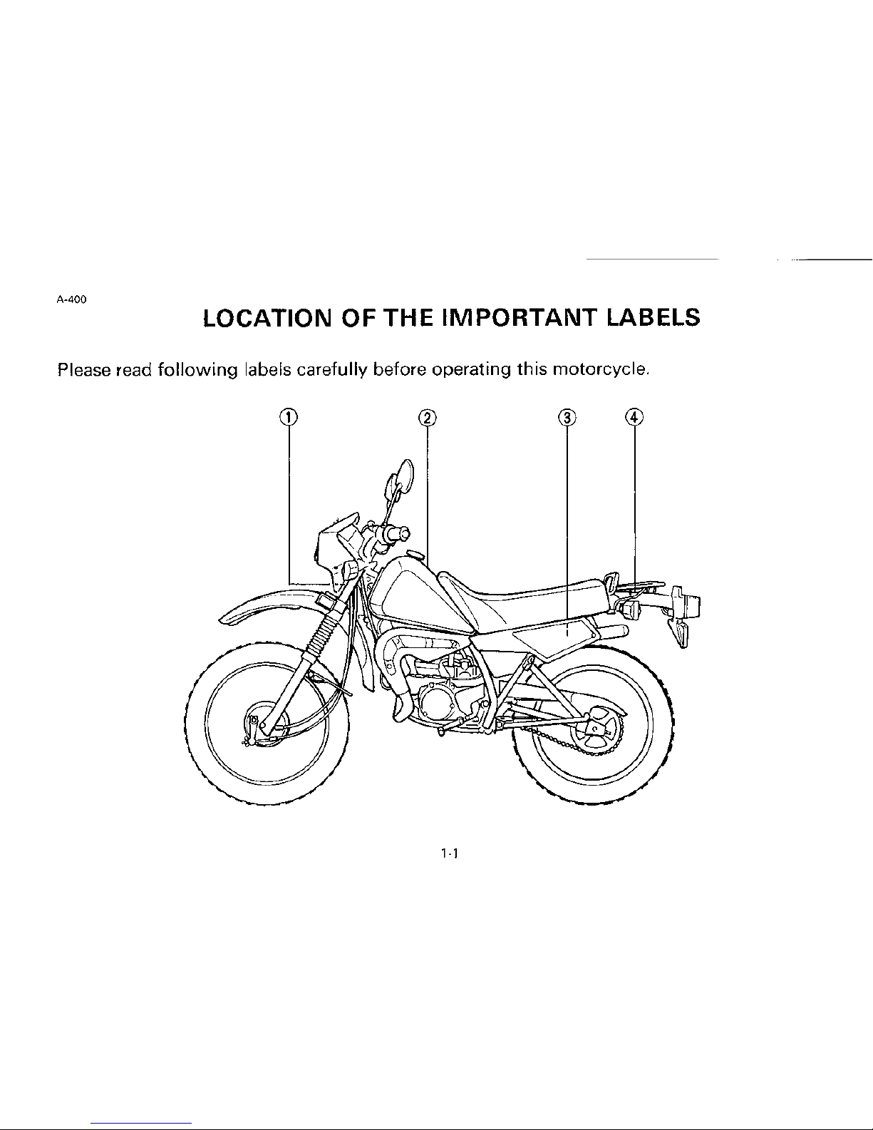
A-400
LOCATION
OF
THE
IMPORTANT
LABELS
Please read
following
labels carefully before operating this motorcycle.
2 3
4
1·1
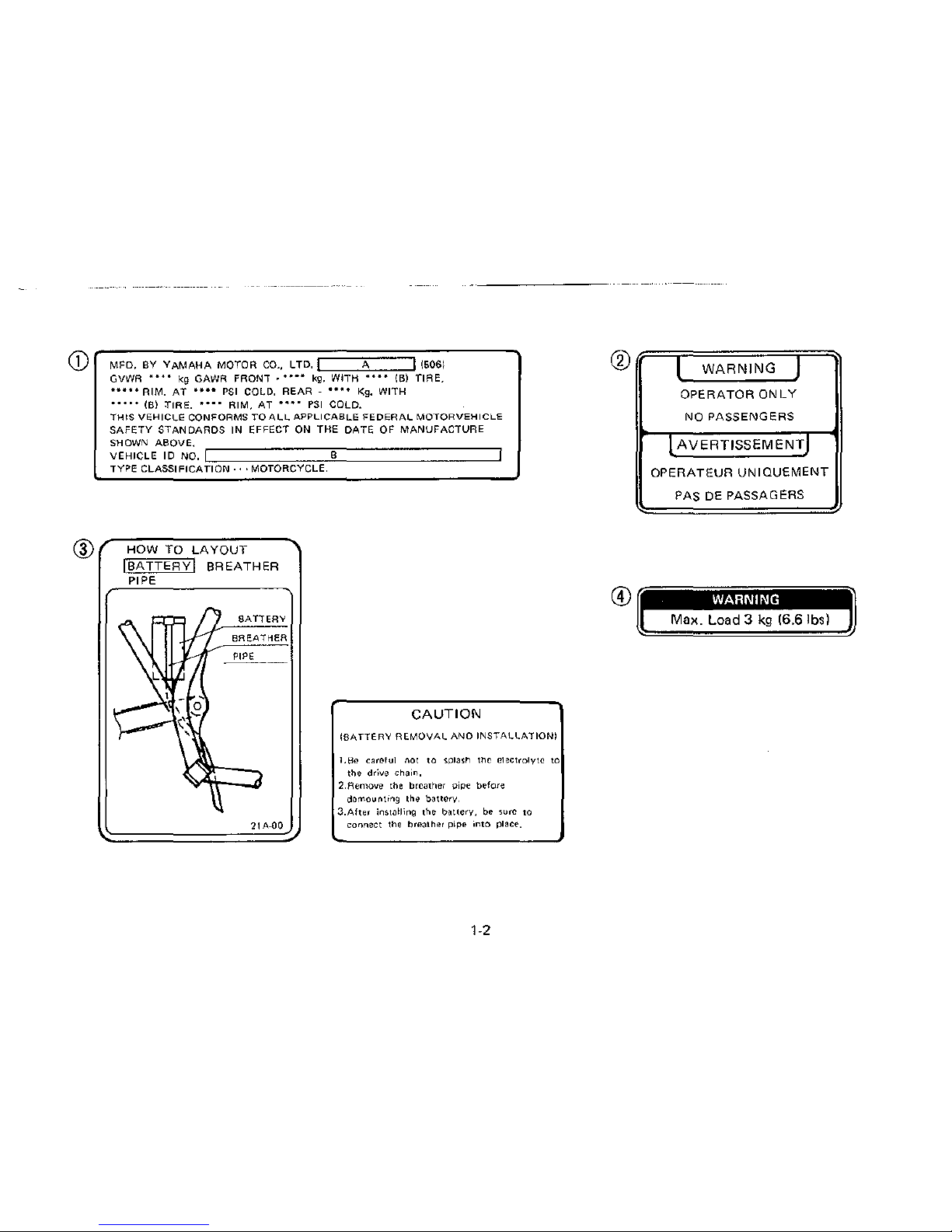
(j)("_M_F_D-.-,-Y~Y-A_M_A_H~A-M~O-T_O_R_C_D-.-.-,-T-D-.:::::::::=A:::::::::;--:-(5:0:6-1~~~~
.....
®
GVWR
••••
kg GAWR FRONT •
••••
kg,
WITH
••••
(B) TIRE,
•••••RIM.
AT
•on
PSI
COLD.
REAR
-
**"•
Kg.
WITH
•••••
(B)
TIRE,
••••
AIM,
AT
••••
PSI
COLD.
THIS
VEHICLE
CONFORMS
TO
ALL
APPLICABLE
FEDERAL
MOTORVEHICLE
SAFETY
STANDARDS
IN EFFECT ON THE
DATE
OF
MANUFACTURE
SHOWN ABOVE.
VEHICLE
ID
NO. 8
TYPE
CLASSIFICATION···
MOTORCYCLE.
HOW TO
LAYOUT
IBATTERYI
BREATHER
PIPE
21A-00
CAUTION
!BATTERY
REMOVAL
ANO
INSTALLATION!
1.Bc
careful
001
10
SPiash
tho
electrolyte
to
the
drive
chain,
2.Remove the breather pipe before
demountrng the
baucry,
3.After
insrnlling
the
battery,
be
sure
10
connect
the
breather
pipe
into
place.
1-2
I
WARNING
I
OPERATOR
ONLY
NO
PASSENGERS
I
AVERTISSEMENTI
OPERATEUR
UNIOUEMENT
PAS DE PASSAGERS
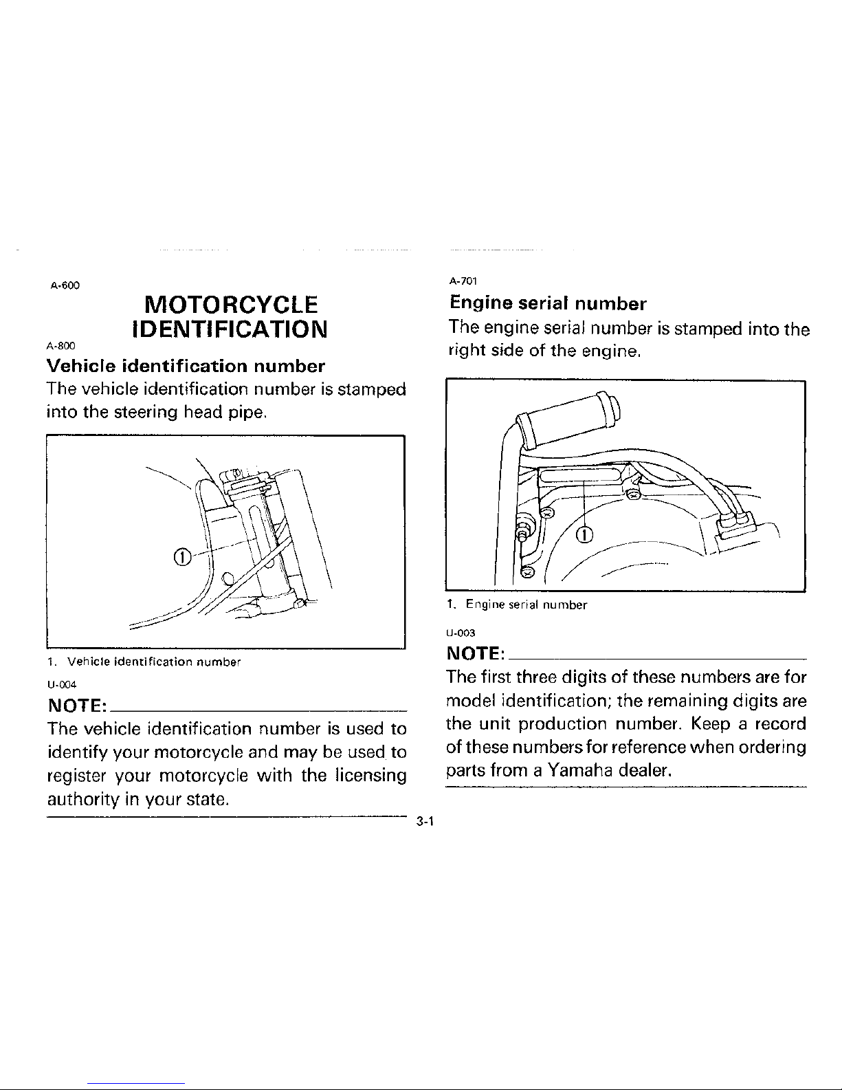
A-500
14
15
j I i
, ; I
\~
DESCRIPTION
2-1
1. Tail/Brake light 12. Silencer
2.
Rear flasher light 13. Change pedal
3.
Monocross suspension
14.
Clutch lever
4. Kick
starter
15. Handlebar switch
5.
Front
fender 16.
Speedometer
6.
Brake pedal
17. Main switch
7.
Footrest
18.
Tachometer
8.
Front
fork
19. Brake lever
9.
Headlight
20.
Throttle
grip
10. Fu et
tank
21.
Front
flasher light
11. Seat
22.
Radiator
U-002
NOTE:
~~~~~~~~~~~~~
The motorcycle you have purchased may differ
slightly from those shown
in
the photographs.
A·600
A-800
MOTORCYCLE
IDENTIFICATION
Vehicle
identification
number
The vehicle identification number
is
stamped
into the steering head pipe.
1.
Vehicle identification number
U-004
NOTE:
___________
_
The vehicle identification number
is
used
to
identify your motorcycle and may be used
to
register your motorcycle
with
the licensing
authority in your state.
------------------
3-1
A-701
Engine serial
number
The engine serial number
is
stamped into the
right side
of
the engine.
1.
Engine
serial
number
U-003
NOTE:
___________
_
The first three digits
of
these numbers
are
for
model identification; the remaining digits
are
the unit production number.
Keep
a record
of
these numbers for reference when ordering
parts from a Yamaha dealer.
B-000
CONTROL
FUNCTIONS
B·001
Main
switch
The main switch controls the ignition and
lighting
systems; its operation
is
described
below.
OFF
ON
B-014
ON:
Electrical circuits
are
switched on and taillight
comes on. The engine can be started. The
key cannot be removed
in
this position.
4'1
U-006
NOTE:~~~~~~~~~~~~
When the engine
is
started, the headlight and
meter
lights come on automatically, and the
lights stay on until the main switch
is
turned
to
"OFF" even
if
the engine stalls.
B-006
OFF:
All
electrical circuits are switched off. The
key can be removed in this position.
8-007
LOCK:
The steering
is
locked
in
this position, and
all electrical circuits are switched off. The key
can be removed in this position. Refer to
"Steering lock" (Page
4-9)
for proper oper-
ation.
U-007
NOTE=~~~~~~~~~~~~
Always
turn the main switch to "OFF" or
"LOCK"
and remove the key when the
mo-
torcycle
is
unattended.
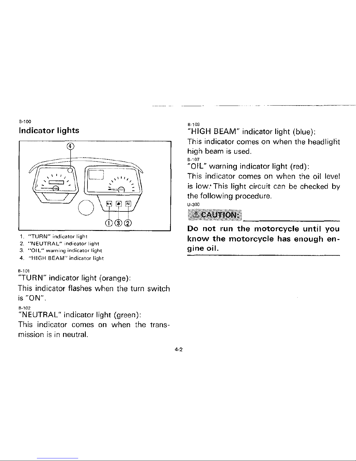
8-100
Indicator
lights
4
CJ
0
1.
"TURN"
indicator
light
2.
"NEUTRAL"
indicator
light
3. "OJ
L"
warning
indicator
light
4.
"HIGH
BEAM"
indicator
light
B-101
"TURN" indicator light (orange):
This indicator flashes when the turn switch
is
"ON".
B-102
"NEUTRAL" indicator light (green):
This indicator comes
on
when the trans-
mission
is
in neutral.
4·2
B-103
"HIGH
BEAM"
indicator light (blue):
This indicator comes on when the headlignt
high beam
is
used.
B-107
"OIL" warning indicator light (red):
This indicator comes on when the
oil level
is
low:
This light circuit
can
be
checked by
the following procedure.
U-300
Do
not
run
the
motorcycle
until
you
know
the
motorcycle
has
enough
en-
gine
oil.
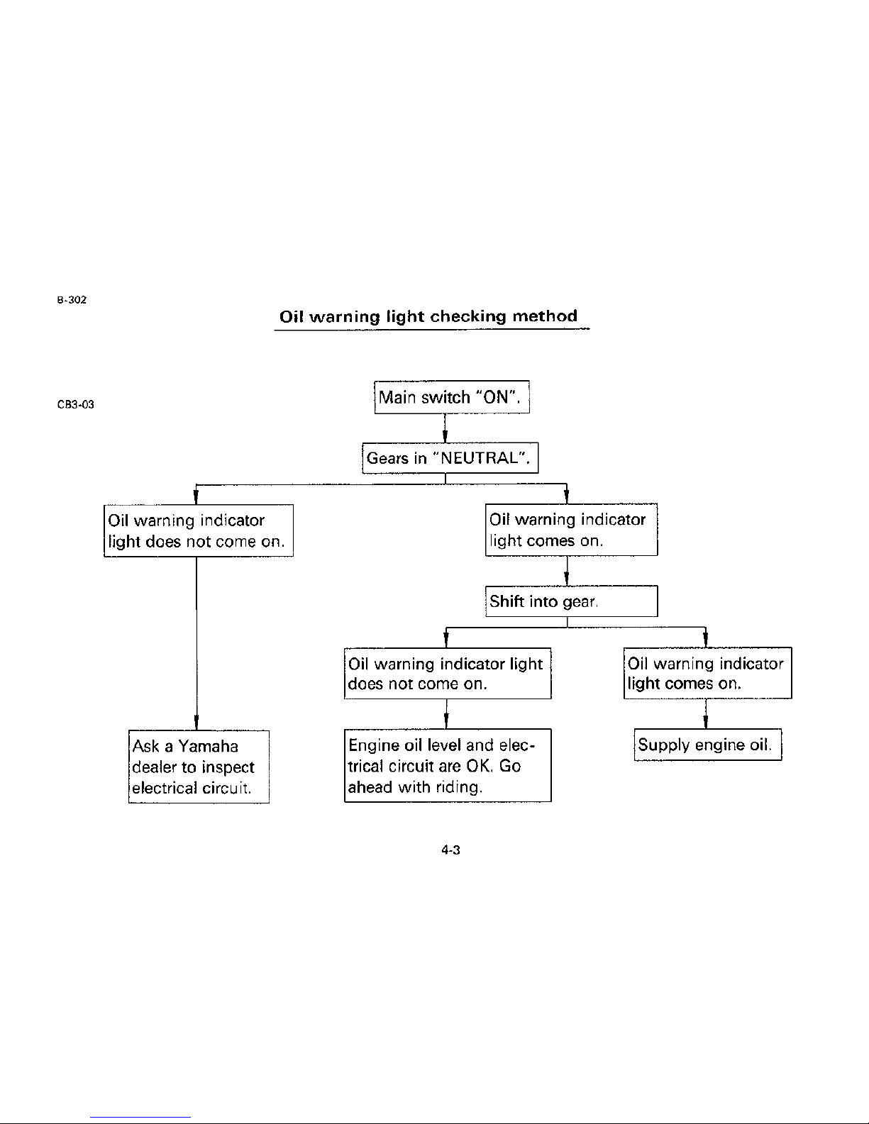
B-302
Oil
warning
light
checking
method
CB3·03
\Main switch "ON". I
I
!Gears
in
"NEUTRAL". I
I
t
t
Oil warning indicator
Oil warning indicator
light does not come on.
light comes on.
j
Shift into
gear.
I
t
I
Oil warning indicator light Oil warning indicator
does not come on. light comes on.
I
I
Ask a Yamaha
Engine
oil level and elec-
!supply
engine oil. I
dealer to inspect
trical circuit
are
OK.
Go
electrical circuit.
ahead with riding.
4-3
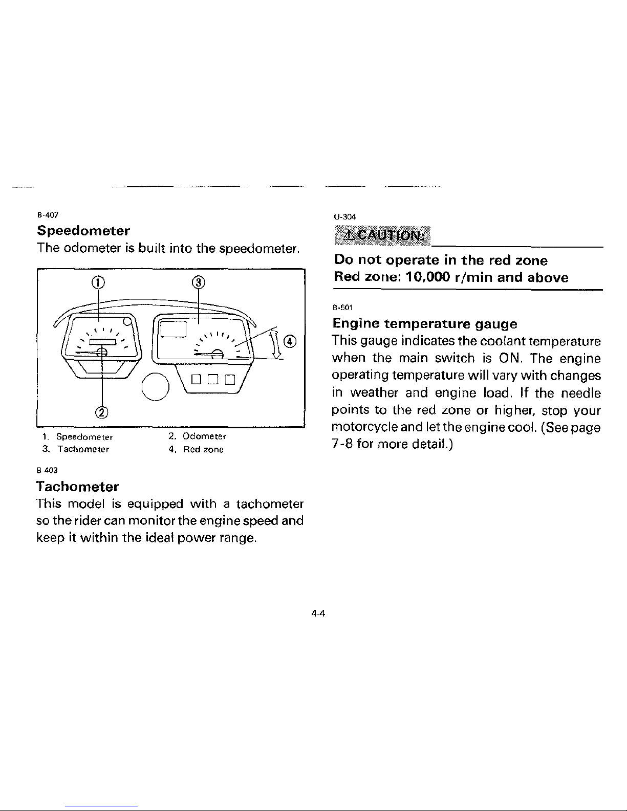
B-407
Speedometer
The odometer is
built
into the speedometer.
2
1.
Speedometer
3. Tachometer
B-403
Tachometer
3
2. Odometer
4. Red zone
This model
is
equipped
with
a tachometer
so the rider can monitor the engine speed and
keep it
within
the ideal
power
range.
4-4
U-304
Do
not
operate
in
the
red zone
Red zone:
10,000
r/min
and above
B-501
Engine
temperature
gauge
This gauge indicates the coolant temperature
when the main
switch
is
ON. The engine
operating temperature
will
vary
with
changes
in weather and engine
load.
If
the
needle
points
to
the red zone or higher, stop
your
motorcycle and let the engine cool. (See page
7-8
for more detail.)
40 C (104
F)
';/
®
c
.-"'.l
I . \ I I
~
.
,,
....
125°C
(257°F)'-
'
-
.. .
....
·-
I
-
1. Engine
temperature
gauge 2. Red
zone
U-305
When
the
engine
is
overheated,
do
not
continue
riding.
4.5
B-600
Handlebar
switches:
2
1.
"LIGHTS"
(Dimmer)
switch
2.
"TURN"
switch
3.
"HORN"
switch
B-601
"LIGHTS"
(Dimmer)
switch
Turn the
switch
to
"HI"
for the high beam
and
to
"LO"
for
the
low
beam.
B-605
"TURN"
signal
switch
This
is a three-way
switch:
the
center position
is
off; turn
to
the
"L"
to
turn on the left flasher
and
to
the
"R"
for the right flasher. Be sure
to
turn the
switch
off
after completing a turn.
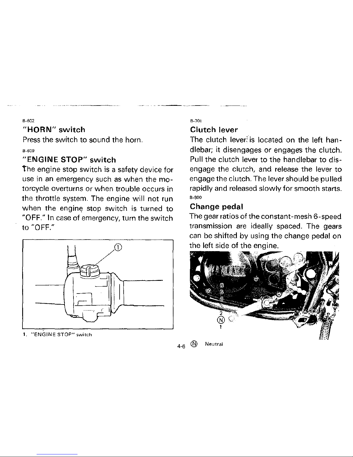
B-602
"HORN"
switch
Press
the switch
to
sound the horn.
B-609
"ENGINE
STOP"
switch
the
engine stop switch
is
a safety device
for
use
in
an
emergency such
as
when
the
mo-
torcycle overturns or when trouble occurs in
the throttle system. The engine
will
not
run
when
the engine stop
switch
is
turned
to
"OFF." In
case
of
emergency, turn the
switch
to "OFF."
1.
"ENGINE
STOP"
switch
B-701
Clutch
lever
The clutch lever:
is
located on the left han-
dlebar;
it
disengages or engages the clutch.
Pull
the clutch lever
to
the handlebar
to
dis-
engage the
clutch, and release the lever
to
engage the clutch. The lever should be pulled
rapidly and released
slowly
for
smooth starts.
B-800
Change pedal
The gear ratios
of
the
constant-mesh 6-speed
transmission
are
ideally spaced. The gears
can be shifted by using
the
change pedal on
the left side
of
the engine.
4
_
6
@ Neutral
B-900
Front brake lever
The front brake lever
is
located on the right
handlebar.
Pull it toward the handlebar to
activate the front brake.
B-901
Rear brake pedal
The
rear
brake pedal
is
on the right side
of
the motorcycle.
Press
down
on the brake
pedal to activate the
rear
brake.
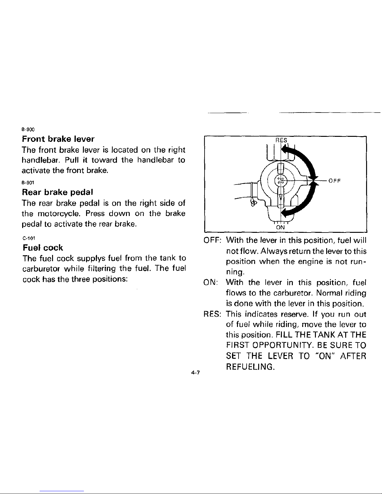
C-101
Fuel cock
The fuel cock supplys fuel from the tank to
carburetor while
filtering the fuel. The fuel
cock has the three positions:
4-7
ON
OFF:
With the lever
in
this position, fuel will
not flow. Always return the lever to this
position when the engine
is
not run-
ning.
ON: With the lever in this position, fuel
flows to the carburetor. Normal riding
is
done with the lever in this position.
RES:
This indicates
reserve.
If you run out
of
fuel while riding, move the lever to
this position.
FILL THE TANK AT THE
FIRST OPPORTUNITY.
BE
SURE
TO
SET
THE
LEVER
TO
"ON"
AFTER
REFUELING.

C-202
Starter
knob (CHOKE)
When cold, the engine requires a richer airfuel mixture for starting. A separate starter
circuit supplies this mixture.
Pull the starter
knob
out
to open the circuit for starting. When
the engine has warmed up, push the knob
in to close the circuit.
:~
1. Starter
knob
4.S
C-602
Kick starter
Rotate the kick starter away from the engine.
Push the starter
down
lightly with your
foot
until the gears engage, then kick smoothly
and forcefully
to
start the engine. This model
has
a primary kick starter so the engine
can
be
started in any gear if the clutch
is
disen-
gaged.
In
normal practices, however, shift
to
neutral before starting.
1. Kick starter
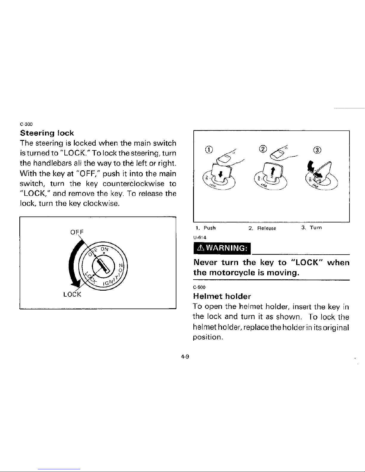
C-300
Steering
lock
The steering
is
locked when the main
switch
is
turned
to
"LOCK." To lock the steering, turn
the handlebars all the way
to
the left or right.
With
the key at "OFF," push it into the main
switch, turn the key
countertlockwise
to
"LOCK," and remove the key. To release the
lock, turn the key clockwise.
OFF
4.9
1. Push
U-614
L1'
WARNING:
2. Release
3.
Turn
Never
turn
the
key
to
"LOCK"
when
the
motorcycle
is
moving.
C-500
Helmet
holder
To open the helmet holder, insert the key
in
the lock and turn it
as
shown. To lock the
helmet holder, replace the holder
in
its original
position.
 Loading...