

OWNER’S MANUAL
DT175(N)
3FJ-28199-2C

EAU00000
INTRODUCTION
Congratulations on your purchase of the Yamaha DT175. This model is the result of Yamaha’s vast
experience in the production of fine sporting, touring, and pacesetting racing machines. It represents
the high degree of craftsmanship and reliability that have made Yamaha a leader in these fields.
This manual will give you an understanding of the operation, inspection, and basic maintenance of
this motorcycle. If you have any questions concerning the operation or maintenance of your motorcycle, please consult a Yamaha dealer.
1
2
4
5
6
7
8
9
IMPORTANT MANUAL INFORMATION
Particularly important information is distinguished in this manual by the following notations:
EAU00005
1
Q
2
3
4
5
6
7
8
9
w
cC
NOTE:
NOTE:
8 This manual should be considered a permanent part of this motorcycle and should remain
8 Yamaha continually seeks advancements in product design and quality. Therefore, while this
The Safety Alert Symbol means ATTENTION! BECOME ALERT! YOUR SAFETY IS
INVOLVED!
Failure to follow WARNING instructions could result in severe injury or death to the
motorcycle operator, a bystander, or a person inspecting or repairing the motorcycle.
A CAUTION indicates special precautions that must be taken to avoid damage to
the motorcycle.
A NOTE provides key information to make procedures easier or clearer.
with it even if the motorcycle is subsequently sold.
manual contains the most current product information available at the time of printing, there
may be minor discrepancies between your motorcycle and this manual. If you have any questions concerning this manual, please consult your Yamaha dealer.
w
IMPORTANT MANUAL INFORMATION
EW000002
PLEASE READ THIS MANUAL CAREFULLY AND COMPLETELY BEFORE OPERATING
THIS MOTORCYCLE.
1
2
4
5
6
7
8
9
1
2
3
4
5
EAU03337
6
DT175(N)
OWNER’S MANUAL
7
©2000 by Yamaha Motor Co., Ltd.
1st Edition, June 2000
8
All rights reserved.
Any reprinting or unauthorized use
9
without the written permission of
Yamaha Motor Co., Ltd.
is expressly prohibited.
Printed in Japan.
EAU00009
TABLE OF CONTENTS
SAFETY INFORMATION.....................................1-1
1
Safe riding.........................................................1-1
Protective apparel.............................................1-3
Modifications.....................................................1-3
Loading and accessories..................................1-3
Gasoline and exhaust gas ................................1-5
Location of important labels..............................1-7
DESCRIPTION ....................................................2-1
2
Left view............................................................2-1
Right view .........................................................2-2
Controls and instruments..................................2-3
INSTRUMENT AND CONTROL FUNCTIONS....3-1
3
Main switch/steering lock..................................3-1
Indicator and warning lights..............................3-2
Speedometer unit .............................................3-3
Tachometer.......................................................3-3
Handlebar switches ..........................................3-3
Clutch lever.......................................................3-4
Shift pedal.........................................................3-5
Brake lever........................................................3-5
Brake pedal.......................................................3-5
Fuel tank cap ....................................................3-6
Fuel...................................................................3-6
2-stroke engine oil ............................................3-7
Fuel cock ..........................................................3-8
Starter (choke) knob .........................................3-9
Kickstarter.........................................................3-9
Seat ................................................................3-10
Helmet holder .................................................3-11
Adjusting the shock absorber assembly .........3-11
YEIS handling precautions .............................3-13
Sidestand........................................................3-13
Ignition circuit cut-off system ..........................3-14
PRE-OPERATION CHECKS...............................4-1
4
Pre-operation check list ....................................4-1
OPERATION AND IMPORTANT RIDING
5
POINTS................................................................5-1
Starting and warming up a cold engine ............5-1
Starting a warm engine.....................................5-2
Shifting..............................................................5-2
Tips for reducing fuel consumption...................5-3
Engine break-in.................................................5-3
Parking..............................................................5-4
PERIODIC MAINTENANCE AND MINOR
6
REPAIR................................................................6-1
Owner’s tool kit .................................................6-1
Periodic maintenance and lubrication chart......6-2
1
2
3
4
5
6
7
8
9
TABLE OF CONTENTS
Removing and installing the cowling and
panels .............................................................6-5
1
2
3
4
5
6
7
8
9
Checking the spark plug ...................................6-6
Transmission oil................................................6-8
Cleaning the air filter element.........................6-10
Adjusting the carburetor..................................6-11
Adjusting the engine idling speed...................6-12
Adjusting the throttle cable free play...............6-12
Tires................................................................6-13
Spoke wheels .................................................6-15
Adjusting the clutch lever free play.................6-16
Adjusting the brake lever free play .................6-17
Adjusting the brake pedal position and
free play........................................................6-17
Adjusting the rear brake light switch...............6-19
Checking the front brake pads and
rear brake shoes...........................................6-19
Checking the brake fluid level.........................6-20
Changing the brake fluid.................................6-21
Drive chain slack.............................................6-21
Lubricating the drive chain..............................6-23
Checking and lubricating the cables...............6-24
Checking and lubricating the throttle grip
and cable ......................................................6-24
Adjusting the autolube pump ..........................6-25
Checking and lubricating the brake and
shift pedals....................................................6-25
Checking and lubricating the brake and
clutch levers..................................................6-26
Checking and lubricating the sidestand..........6-26
Lubricating the rear suspension......................6-26
Checking the front fork....................................6-27
Checking the steering.....................................6-27
Checking the wheel bearings..........................6-28
Battery ............................................................6-28
Replacing the fuse..........................................6-30
Replacing the headlight bulb ..........................6-31
Replacing a turn signal light bulb....................6-33
Replacing the tail/brake light bulb...................6-33
Supporting the motorcycle..............................6-33
Front wheel.....................................................6-34
Rear wheel......................................................6-36
Troubleshooting..............................................6-37
Troubleshooting chart.....................................6-38
MOTORCYCLE CARE AND STORAGE .............7-1
7
Care..................................................................7-1
Storage .............................................................7-4
SPECIFICATIONS...............................................8-1
8
Conversion table...............................................8-5
CONSUMER INFORMATION..............................9-1
9
Identification numbers.......................................9-1
Key identification number .................................9-1
Vehicle identification number............................9-1
Model label .......................................................9-2
Motorcycle noise regulation (for Australia) .......9-2
TABLE OF CONTENTS
1
2
3
4
5
6
7
8
9

Q SAFETY INFORMATION
MOTORCYCLES ARE SINGLE TRACK VEHICLES. THEIR SAFE USE AND OPERATION ARE
DEPENDENT UPON THE USE OF PROPER RIDING TECHNIQUES AS WELL AS THE EXPER-
1
TISE OF THE OPERATOR. EVERY OPERATOR SHOULD KNOW THE FOLLOWING REQUIREMENTS BEFORE RIDING THIS MOTORCYCLE.
EAU00017
2
3
4
5
6
7
8
9
HE OR SHE SHOULD:
1. OBTAIN THOROUGH INSTRUCTIONS FROM A COMPETENT SOURCE ON ALL ASPECTS
OF MOTORCYCLE OPERATION.
2. OBSERVE THE WARNINGS AND MAINTENANCE REQUIREMENTS IN THE OWNER’S MANUAL.
3. OBTAIN QUALIFIED TRAINING IN SAFE AND PROPER RIDING TECHNIQUES.
4. OBTAIN PROFESSIONAL TECHNICAL SERVICE AS INDICATED BY THE OWNER’S MANUAL
AND/OR WHEN MADE NECESSARY BY MECHANICAL CONDITIONS.
Safe riding
1. Always make pre-operation checks. Careful checks may help prevent an accident.
2. This motorcycle is designed to carry the operator and a passenger.
3. The failure of motorists to detect and recognize motorcycles in traffic is the predominating cause
of automobile/motorcycle accidents. Many accidents have been caused by an automobile driver
who did not see the motorcycle. Making yourself conspicuous appears to be very effective in
reducing the chance of this type of accident.
Therefore:
a. Wear a brightly colored jacket.
b. Use extra caution when approaching and passing through intersections, since intersections
are the most likely places for motorcycle accidents to occur.
c. Ride where other motorists can see you. Avoid riding in another motorist’s blind spot.
1-1

Q SAFETY INFORMATION
4. Many accidents involve inexperienced operators. In fact, many operators who have been
involved in accidents do not even have a current motorcycle license.
a. Make sure that you are qualified and that you only lend your motorcycle to other qualified oper-
ators.
b. Know your skills and limits. Staying within your limits may help you to avoid an accident.
c. We recommend that you practice riding your motorcycle where there is no traffic until you have
become thoroughly familiar with the motorcycle and all of its controls.
5. Many accidents have been caused by error of the motorcycle operator. A typical error made by
the operator is veering wide on a turn due to EXCESSIVE SPEED or undercornering (insufficient
lean angle for the speed).
a. Always obey the speed limit and never travel faster than warranted by road and traffic condi-
tions.
b. Always signal before turning or changing lanes. Make sure that other motorists can see you.
6. The posture of the operator and passenger is important for proper control.
a. The operator should keep both hands on the handlebar and both feet on the operator footrests
during operation to maintain control of the motorcycle.
b. The passenger should always hold onto the operator, the seat strap or grab bar, if equipped,
with both hands and keep both feet on the passenger footrests.
c. Never carry a passenger unless he or she can firmly place both feet on the passenger
footrests.
7. Never ride under the influence of alcohol or other drugs.
1
2
3
4
5
6
7
8
9
1-2

Q SAFETY INFORMATION
Protective apparel
The majority of fatalities from motorcycle accidents are the result of head injuries. The use of a safety
1
2
3
4
5
helmet is the single most critical factor in the prevention or reduction of head injuries.
1. Always wear an approved helmet.
2. Wear a face shield or goggles. Wind in your unprotected eyes could contribute to an impairment
of vision that could delay seeing a hazard.
3. The use of a jacket, heavy boots, trousers, gloves, etc., is effective in preventing or reducing
abrasions or lacerations.
4. Never wear loose-fitting clothes, otherwise they could catch on the control levers, footrests, or
wheels and cause injury or an accident.
5. Never touch the engine or exhaust system during or after operation. They become very hot and
can cause burns. Always wear protective clothing that covers your legs, ankles, and feet.
6. Passengers should also observe the precautions mentioned above.
6
7
8
9
Modifications
Modifications made to this motorcycle not approved by Yamaha, or the removal of original equipment,
may render the motorcycle unsafe for use and may cause severe personal injury. Modifications may
also make your motorcycle illegal to use.
Loading and accessories
Adding accessories or cargo to your motorcycle can adversely affect stability and handling if the
weight distribution of the motorcycle is changed. To avoid the possibility of an accident, use extreme
caution when adding cargo or accessories to your motorcycle. Use extra care when riding a motorcycle that has added cargo or accessories. Here are some general guidelines to follow if loading cargo
or adding accessories to your motorcycle:
1-3

Q SAFETY INFORMATION
Loading
The total weight of the operator, passenger, accessories and cargo must not exceed the maximum
load limit of 180 kg. When loading within this weight limit, keep the following in mind:
1. Cargo and accessory weight should be kept as low and close to the motorcycle as possible.
Make sure to distribute the weight as evenly as possible on both sides of the motorcycle to minimize imbalance or instability.
2. Shifting weights can create a sudden imbalance. Make sure that accessories and cargo are
securely attached to the motorcycle before riding. Check accessory mounts and cargo restraints
frequently.
3. Never attach any large or heavy items to the handlebar, front fork, or front fender. These items,
including such cargo as sleeping bags, duffel bags, or tents, can create unstable handling or a
slow steering response.
1
2
3
4
5
Accessories
Genuine Yamaha accessories have been specifically designed for use on this motorcycle. Since
Yamaha cannot test all other accessories that may be available, you must personally be responsible
for the proper selection, installation and use of non-Yamaha accessories. Use extreme caution when
selecting and installing any accessories.
Keep the following guidelines in mind, as well as those provided under “Loading” when mounting
accessories.
1. Never install accessories or carry cargo that would impair the performance of your motorcycle.
Carefully inspect the accessory before using it to make sure that it does not in any way reduce
ground clearance or cornering clearance, limit suspension travel, steering travel or control operation, or obscure lights or reflectors.
1-4
6
7
8
9

Q SAFETY INFORMATION
a. Accessories fitted to the handlebar or the front fork area can create instability due to improper
weight distribution or aerodynamic changes. If accessories are added to the handlebar or front
1
2
3
4
5
6
7
8
9
Gasoline and exhaust gas
fork area, they must be as lightweight as possible and should be kept to a minimum.
b. Bulky or large accessories may seriously affect the stability of the motorcycle due to aerody-
namic effects. Wind may attempt to lift the motorcycle, or the motorcycle may become unstable
in cross winds. These accessories may also cause instability when passing or being passed by
large vehicles.
c. Certain accessories can displace the operator from his or her normal riding position. This
improper position limits the freedom of movement of the operator and may limit control ability,
therefore, such accessories are not recommended.
2. Use caution when adding electrical accessories. If electrical accessories exceed the capacity of
the motorcycle’s electrical system an electric failure could result, which could cause a dangerous
loss of lights or engine power.
1. GASOLINE IS HIGHLY FLAMMABLE:
a. Always turn the engine off when refueling.
b. Take care not to spill any gasoline on the engine or exhaust system when refueling.
c. Never refuel while smoking or in the vicinity of an open flame.
2. Never start the engine or let it run for any length of time in a closed area. The exhaust fumes are
poisonous and may cause loss of consciousness and death within a short time. Always operate
your motorcycle in an area that has adequate ventilation.
3. Always turn the engine off before leaving the motorcycle unattended and remove the key from
the main switch. When parking the motorcycle, note the following:
1-5

Q SAFETY INFORMATION
a. The engine and exhaust system may be hot, therefore, park the motorcycle in a place where
pedestrians or children are not likely to touch these hot areas.
b. Do not park the motorcycle on a slope or soft ground, otherwise it may fall over.
c. Do not park the motorcycle near a flammable source (e.g., a kerosene heater, or near an open
flame), otherwise it could catch fire.
4. When transporting the motorcycle in another vehicle, make sure that it is kept upright and that the
fuel cock(s) are turned to “ON” or “RES” (for vacuum type)/“OFF” (for manual type). If the motorcycle should lean over, gasoline may leak out of the carburetor or fuel tank.
5. If you should swallow any gasoline, inhale a lot of gasoline vapor, or allow gasoline to get into
your eyes, see your doctor immediately. If any gasoline spills on your skin or clothing, immediately wash the affected area with soap and water and change your clothes.
1
2
3
4
5
6
7
8
9
1-6
Q SAFETY INFORMATION
2
1
Location of important labels
Please read the following important labels carefully before operating this motorcycle.
1
2
3
EAU02977
4
5
6
7
8
9
1-7
WARNING
Before you operate this vehicle,
read the owner’s manual.
English
3HP-21568-00
4AA-22259-40
1 2
Q SAFETY INFORMATION
1
2
3
4
5
6
7
8
9
1-8
DESCRIPTION
1
2
3
4
5
6
7
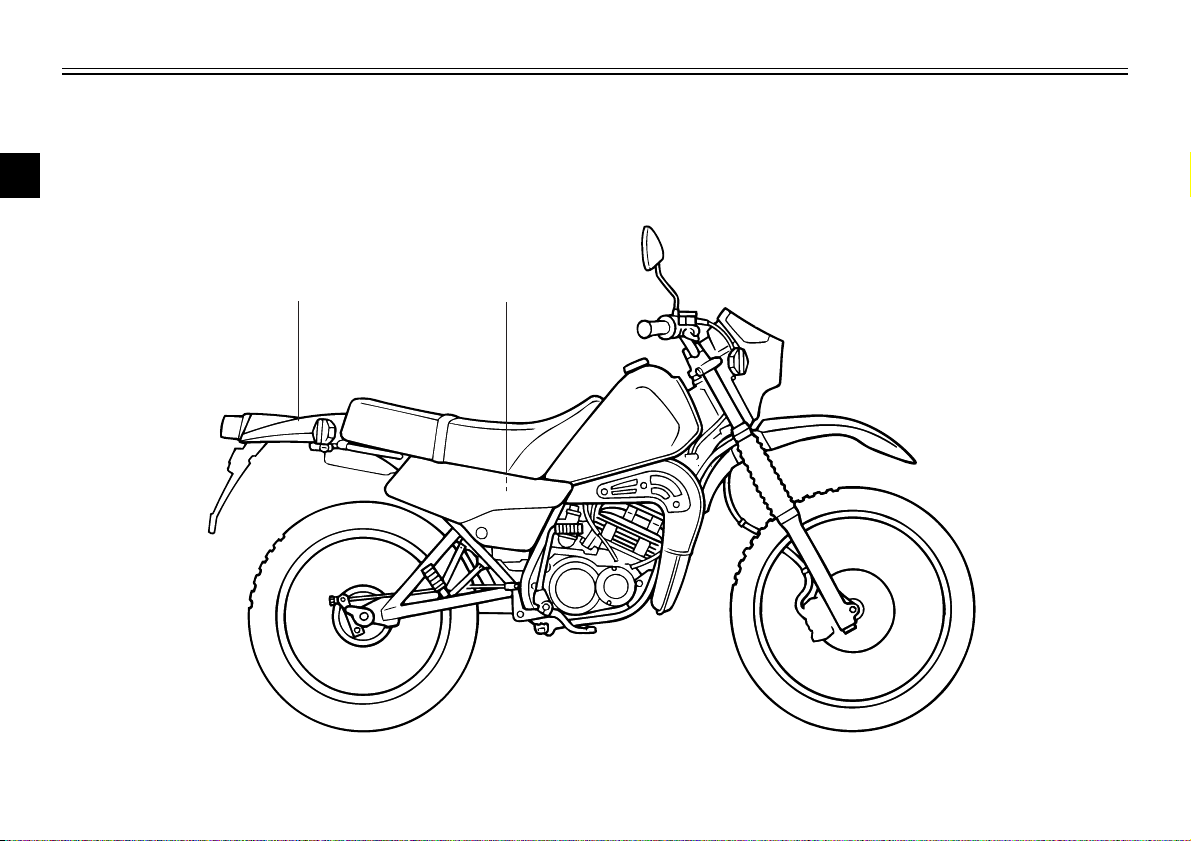
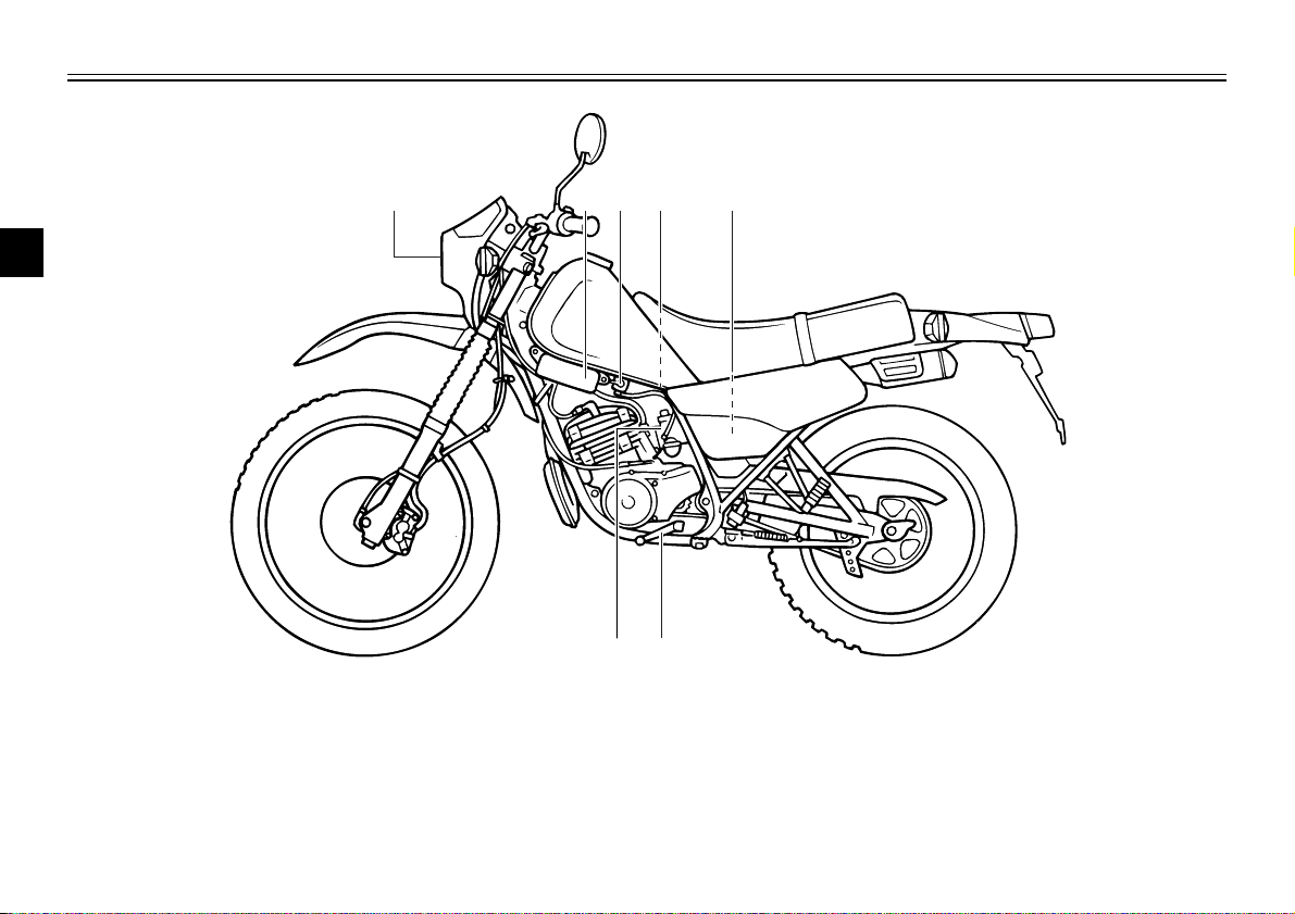
Left view
1
2
3
4
EAU00026
5
6
7
8
9
1. Headlight (page 6-31)
2. YEIS (Yamaha Energy Induction
System) (page 3-13)
3. Fuel cock (page 3-8)
4. Rear shock absorber spring preload
adjusting ring (page 3-11)
5. Air filter element (page 6-10)
6. Shift pedal (page 3-5, 5-2)
7. Starter (choke) knob (page 3-9)
2-1
8
9 10
11121314
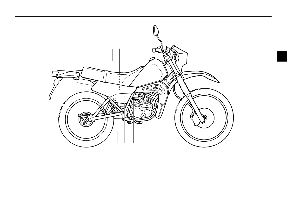
Right view
DESCRIPTION
1
2
3
4
8. Helmet holder (page 3-11)
9. Owner’s tool kit (page 6-1)
10. 2-stroke engine oil tank (page 3-7)
11. Brake pedal (page 3-5, 6-17)
12. Kick starter (page 3-9)
13. Battery (page 6-28)
14. Fuse (page 6-30)
2-2
5
6
7
8
9
DESCRIPTION
1 2 3 4 5
6
7
8
9
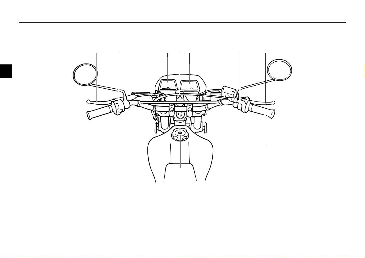
Controls and instruments
1
2
3
4
5
6
7
8
9
1. Clutch lever (page 3-4, 6-16)
2. Left handlebar switches (page 3-3)
3. Speedometer unit (page 3-3)
4. Main switch/steering lock (page 3-1)
5. Tachometer (page 3-3)
6. Right handlebar switch (page 3-4)
7. Brake lever (page 3-5, 6-17)
8. Throttle grip (page 6-12, 6-24)
9. Fuel tank cap (page 3-6)
2-3
LOCK
OFF
ON
EAU00027
1 2 3
OFF (Push)
LOCK
INSTRUMENT AND CONTROL FUNCTIONS
1
2
3
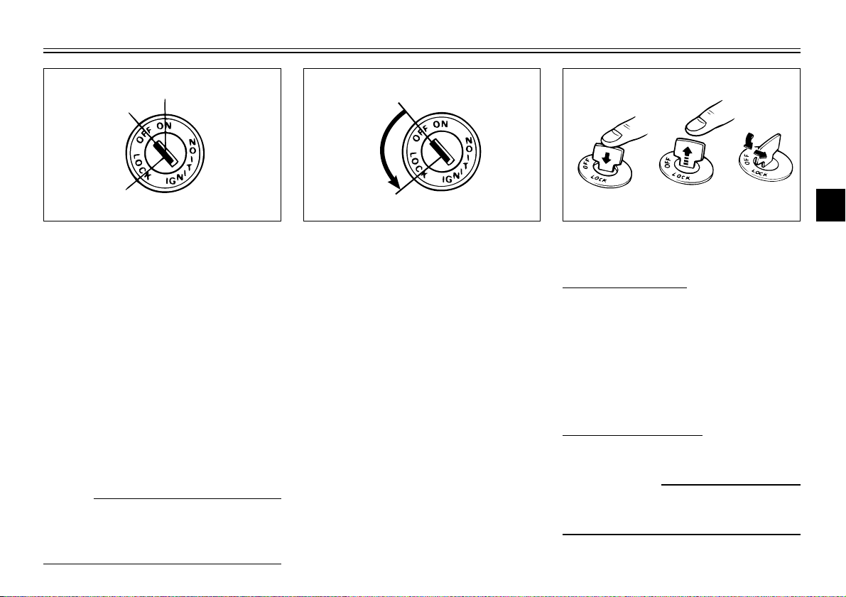
Main switch/steering lock
The main switch/steering lock controls the ignition and lighting systems,
and is used to lock the steering. The
various positions are described
below.
ON
All electrical circuits are supplied with
power, and the engine can be started. The key cannot be removed.
NOTE:
The headlight, meter lighting and taillight come on automatically when the
engine is started.
EAU00029
EAU00037
EAU00038
OFF
All electrical systems are off. The key
can be removed.
EAU00043
LOCK
The steering is locked, and all electrical systems are off. The key can be
removed.
3-1
1. Push.
2. Release.
3. Turn.
To lock the steering
1. Turn the handlebars all the way
to the left or right.
2. Push the key in from the “OFF”
position, release it, and then turn
it to “LOCK”.
3. Remove the key.
To unlock the steering
Insert the key and turn it to “OFF”.
EW000017
w
Never turn the key to “LOCK”
while the motorcycle is moving.
4
5
6
7
8
9
INSTRUMENT AND CONTROL FUNCTIONS
4
1 2
3
1
2
3
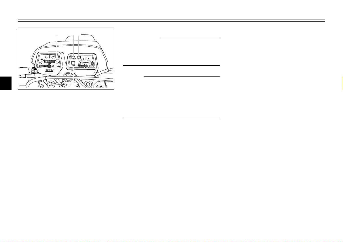
1. Oil level warning light “OIL”
4
2. High beam indicator light “HIGH BEAM”
3. Neutral indicator light “NEUTRAL”
4. Turn indicator light “TURN”
5
Indicator and warning lights
6
Oil level warning light "OIL"
7
This warning light comes on when
the engine oil level is low.
8
The electrical circuit of the warning
light can be checked according to the
9
following procedure.
1. Turn the key to "ON".
2. Shift the transmission into the
neutral position.
3. If the warning light does not
come on, have a Yamaha dealer
check the electrical circuit.
EAU03034
EAU03507
EC000000
cC
Do not operate the motorcycle
until you know that the engine oil
level is sufficient.
NOTE:
Even if the oil level is sufficient, the
warning light may flicker when riding
on a slope or during sudden acceleration or deceleration, but this is not a
malfunction.
EAU00064
High beam indicator light “HIGH
BEAM”
This indicator light comes on when
the high beam of the headlight is
switched on.
EAU00062
Neutral indicator light “NEUTRAL”
This indicator light comes on when
the transmission is in the neutral
position.
3-2
EAU00059
Turn signal indicator light “TURN”
This indicator light flashes when the
turn signal switch is pushed to the left
or right.
INSTRUMENT AND CONTROL FUNCTIONS
1
a
1
2
4
3
1
2
3
1
2
3
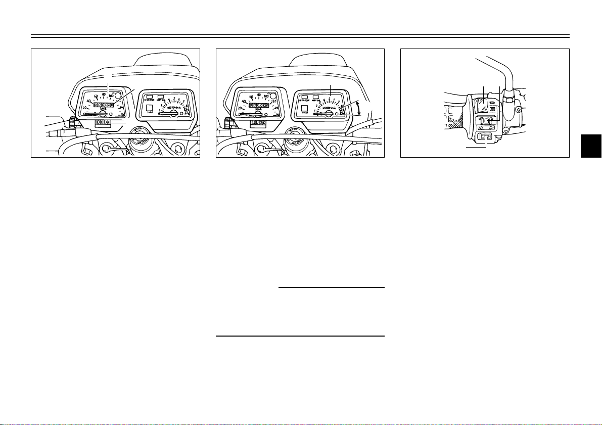
1. Speedometer
2. Odometer
3. Tripmeter
4. Reset knob
Speedometer unit
The speedometer unit is equipped
with a speedometer, an odometer
and a tripmeter. The speedometer
shows riding speed. The odometer
shows the total distance traveled.
The tripmeter shows the distance
traveled since it was last set to zero
with the reset knob. The tripmeter
can be used to estimate the distance
that can be traveled with a full tank of
fuel. This information will enable you
to plan future fuel stops.
EAU00095
1. Tachometer
a. Red zone
EAU00102
Tachometer
This model is equipped with a
tachometer so the rider can monitor
the engine speed and keep it within
the ideal power range.
EC000003
cC
Do not operate the engine in the
tachometer red zone.
Red zone: 8,500 r/min and above
3-3
1. Dimmer switch
2. Turn signal switch
3. Horn switch “*”
EAU00118
Handlebar switches
EAU00121
Dimmer switch
Set this switch to “&” for the high
beam and to “%” for the low beam.
4
5
6
7
8
9
INSTRUMENT AND CONTROL FUNCTIONS
1
1
1
2
3
1
2
3
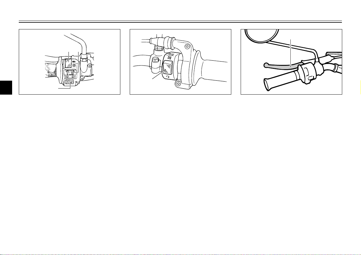
1. Dimmer switch
4
2. Turn signal switch
3. Horn switch “*”
5
Turn signal switch
To signal a right-hand turn, push this
6
switch to “6”. To signal a left-hand
turn, push this switch to “4”. When
7
released, the switch returns to the
center position. To cancel the turn
signal lights, push the switch in after
8
it has returned to the center position.
9
Horn switch “*”
Press this switch to sound the horn.
EAU00127
EAU00129
1. Engine stop switch
EAU00138
Engine stop switch
Set this switch to “$” to stop the
engine in case of an emergency,
such as when the motorcycle overturns or when the throttle cable is
stuck.
3-4
1. Clutch lever
EAU00155
Clutch lever
The clutch lever is located at the left
handlebar grip. To disengage the
clutch, pull the lever toward the handlebar grip. To engage the clutch,
release the lever. The lever should
be pulled rapidly and released slowly
for smooth clutch operation.
INSTRUMENT AND CONTROL FUNCTIONS
1
1
5
4
3
2
1
N
6
1
1
2
3
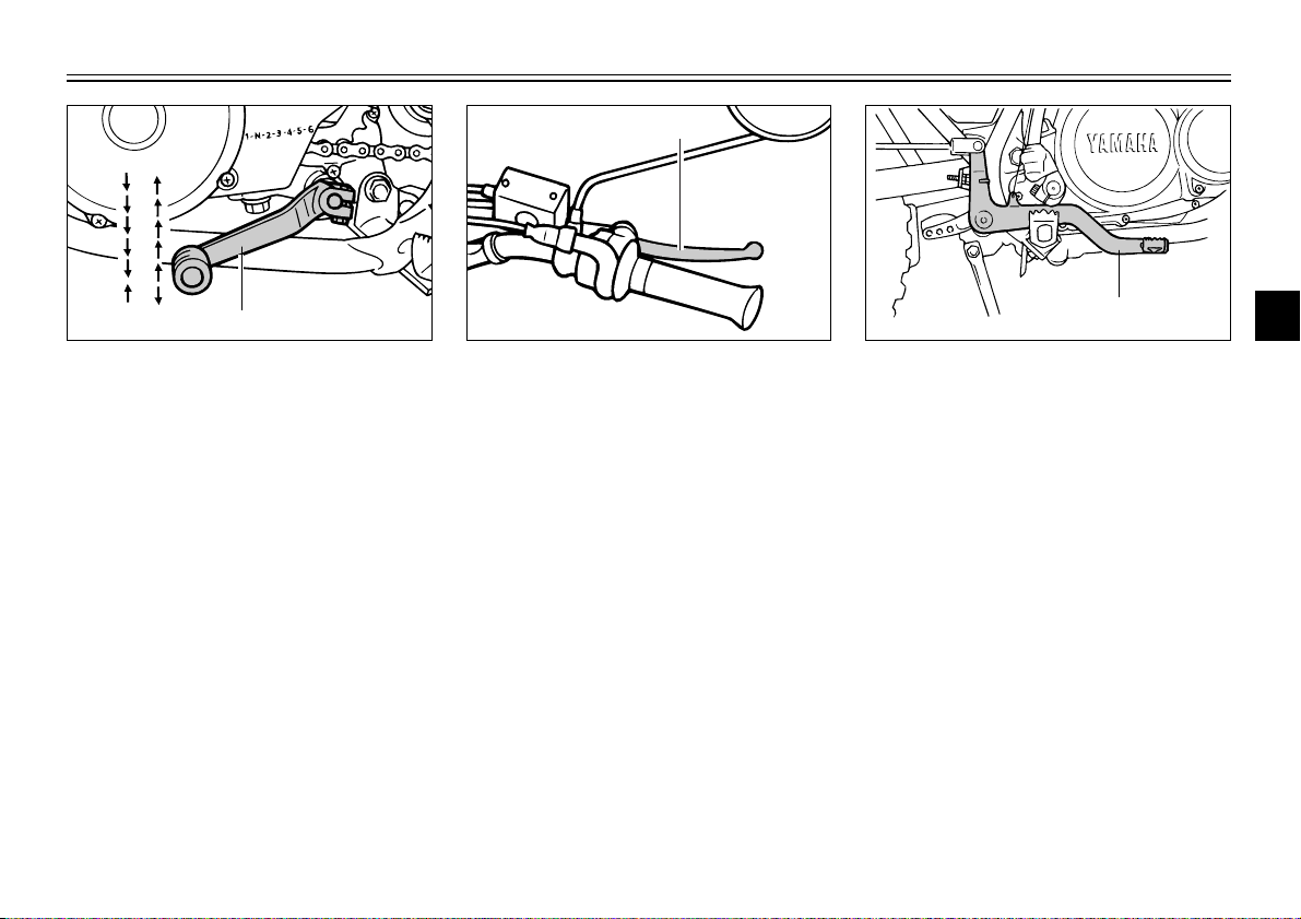
1. Shift pedal
N. Neutral
EAU00157
Shift pedal
The shift pedal is located on the left
side of the engine and is used in
combination with the clutch lever
when shifting the gears of the
6-speed constant-mesh transmission
equipped on this motorcycle.
1. Brake lever
EAU00158
Brake lever
The brake lever is located at the right
handlebar grip. To apply the front
brake, pull the lever toward the handlebar grip.
3-5
1. Brake pedal
EAU00162
Brake pedal
The brake pedal is on the right side
of the motorcycle. To apply the rear
brake, press down on the brake
pedal.
4
5
6
7
8
9
INSTRUMENT AND CONTROL FUNCTIONS
b
1
a
1
2
NOTE:
The fuel tank cap cannot be installed
1
2
unless the key is in the lock. In addition, the key cannot be removed if the
cap is not properly installed and
locked.
3
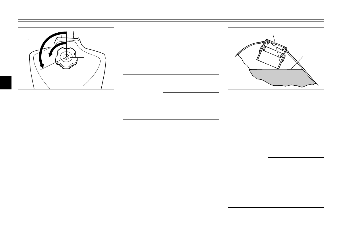
1. Fuel tank cap
4
a. Unlock
b. Open
5
Fuel tank cap
6
To remove the fuel tank cap
1. Insert the key into the lock and
7
turn it 1/4 turn counterclockwise.
2. Turn the fuel tank cap 1/3 turn
8
9
counterclockwise and pull it off.
To install the fuel tank cap
1. Insert the fuel tank cap into the
tank opening with the key inserted in the lock, and then turn the
cap 1/3 turn clockwise.
2. Turn the key 1/4 turn clockwise,
and then remove it.
EAU00177
EW000023
w
Make sure that the fuel tank cap is
properly closed and locked before
riding.
3-6
1. Filler tube
2. Fuel level
EAU01183
Fuel
Make sure that there is sufficient fuel
in the tank. Fill the fuel tank to the
bottom of the filler tube as shown in
the illustration.
EW000130
w
8 Do not overfill the fuel tank,
otherwise it may overflow
when the fuel warms up and
expands.
8 Avoid spilling fuel on the hot
engine.
INSTRUMENT AND CONTROL FUNCTIONS
EAU00185
cC
Immediately wipe off spilled fuel
with a clean, dry, soft cloth, since
fuel may deteriorate painted surfaces or plastic parts.
EAU00192
Recommended fuel:
Regular gasoline
For Australia:
Unleaded fuel only
Fuel tank capacity:
Total amount:
9.5 L
Reserve amount:
1.0 L
EAU03480
2-stroke engine oil
Make sure that there is sufficient oil in
the 2-stroke engine oil tank. If necessary, add the recommended 2-stroke
engine oil as follows.
NOTE:
The motorcycle must be placed on a
level surface and resting on the sidestand for an accurate oil level reading.
1. Remove panel B. (See page 6-6
for panel removal and installation
procedures.)
3-7
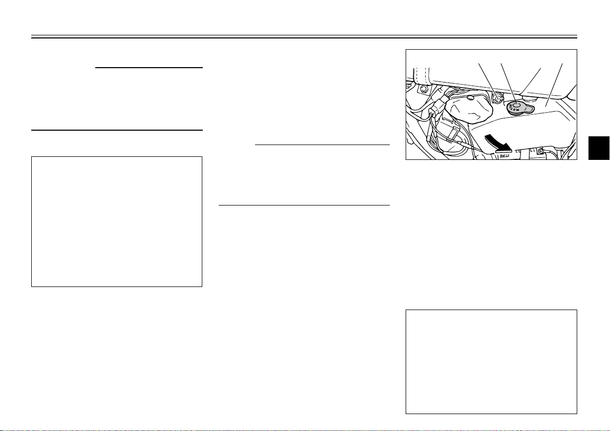
3
2
1. 2-stroke engine oil tank
2. Oil tank filler cap
3. Wing nut
2. Remove the wing nut, and then
slightly pull the 2-stroke engine
oil tank out.
3. Remove the 2-stroke engine oil
tank cap.
4. Fill the oil tank with the recommended 2-stroke engine oil, and
then install the cap.
Recommended oil:
Yamalube 2 or equivalent
2-stroke engine oil (JASO
grade “FC”)
Oil quantity:
Total amount
0.9 L
1
1
2
3
4
5
6
7
8
9
INSTRUMENT AND CONTROL FUNCTIONS
PRIRES
ON
ON
F
U
E
L
1
1
RES: reserve positionON: normal position
E
U
L
F
PRIRESRES
2
3
4
NOTE:
Make sure that the 2-stroke engine
5
oil tank cap is properly installed.
6
5. Place the 2-stroke engine oil
7
tank in the original position, and
then install and tighten the wing
nut.
8
6. Install the panel.
9
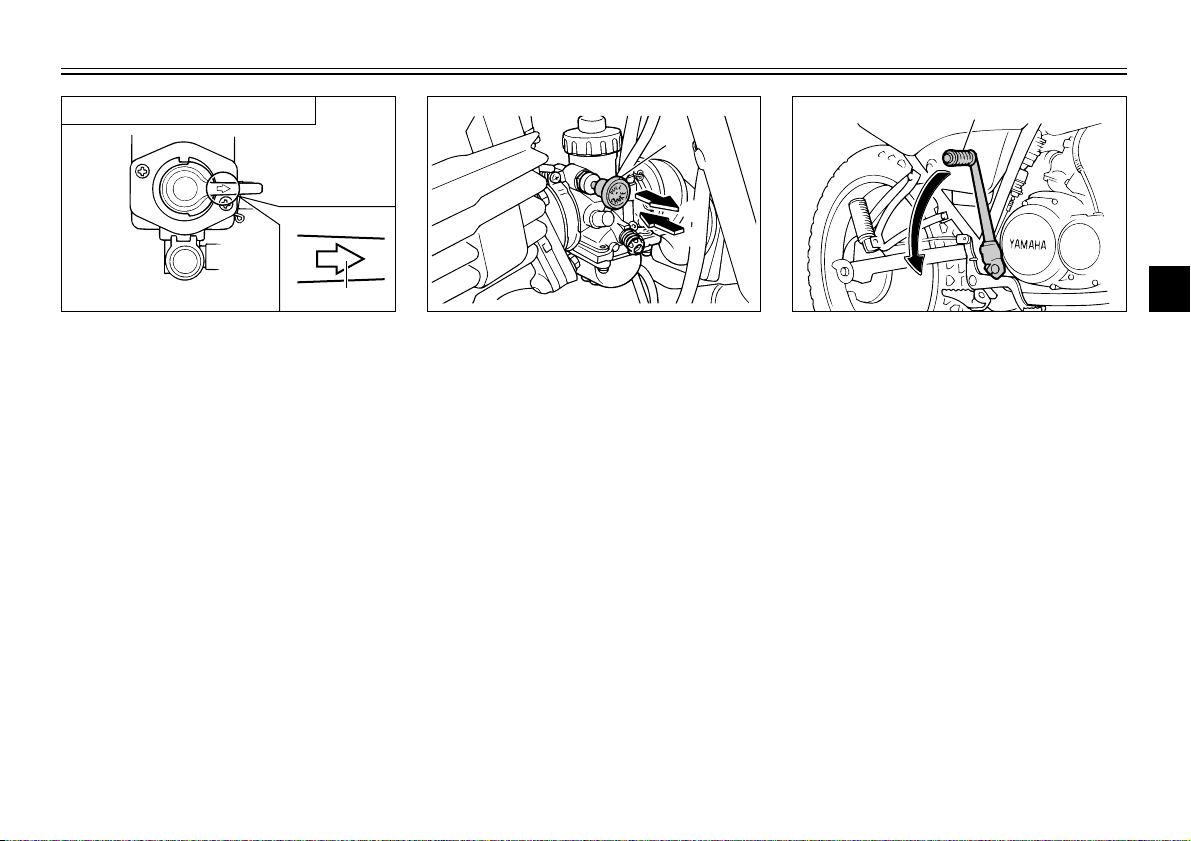
ON
1
1. Arrow mark positioned over “ON”
EAU03236
Fuel cock
This motorcycle is equipped with a
negative pressure fuel cock. The fuel
cock supplies fuel from the tank to
the carburetors while also filtering it.
The fuel cock lever positions are
explained as follows and shown in
the illustrations.
ON
With the fuel cock lever in this position, fuel flows to the carburetor when
the engine is running. Turn the fuel
cock lever to this position when starting the engine and riding.
3-8
1. Arrow mark positioned over “RES”
RES
This indicates reserve. With the fuel
cock lever in this position, the fuel
reserve is made available. Quickly
turn the fuel cock lever to this position if you run out of fuel while riding,
otherwise the engine may stall and
will have to be primed (see “PRI”).
After turning the fuel cock lever to
“RES”, refuel as soon as possible
and be sure to turn the fuel cock
lever back to “ON”!
PRI PRIRES
ON
F
U
E
L
1
1
a
b
1
PRI: priming position
INSTRUMENT AND CONTROL FUNCTIONS
1
2
3
1. Arrow mark positioned over “PRI”
PRI
This indicates prime. With the fuel
cock lever in this position, the engine
can be “primed”. Turn the fuel cock
lever to this position when the engine
has been allowed to run out of fuel.
This sends fuel directly to the carburetor, which will make starting easier.
After the engine has started, be sure
to turn the lever to “ON” (or “RES” if
you have not refueled yet).
1. Starter (choke) knob
EAU03029
Starter (choke) knob
Starting a cold engine requires a richer air-fuel mixture, which is supplied
by the starter (choke).
Move the knob in direction a to turn
on the starter (choke).
Move the knob in direction b to turn
off the starter (choke).
3-9
1. Kickstarter
EAU00213
Kickstarter
To start the engine, raise the right
passenger footrest, fold out the kickstarter lever, move it down lightly with
your foot until the gears engage, and
then push it down smoothly but forcefully. This model is equipped with a
primary kickstarter, allowing the
engine to be started in any gear if the
clutch is disengaged. However, shifting the transmission into the neutral
position before starting is recommended.
4
5
6
7
8
9
INSTRUMENT AND CONTROL FUNCTIONS
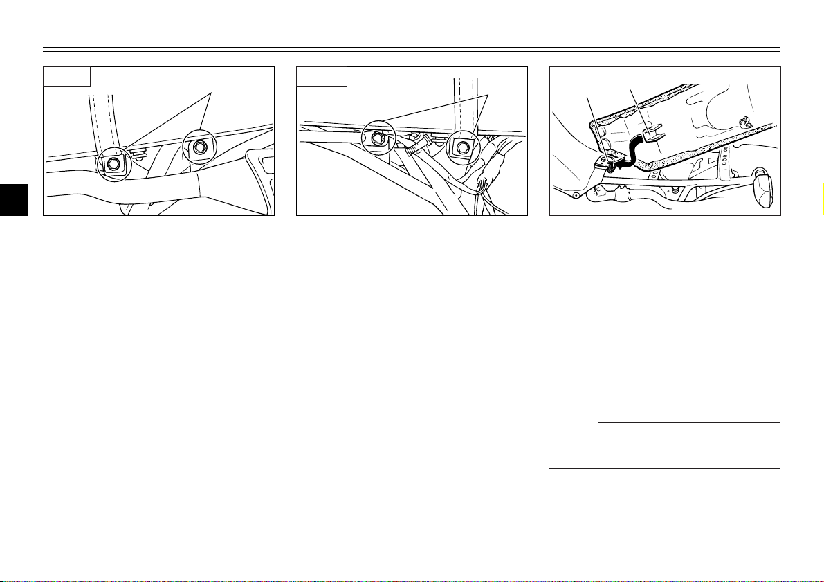
1
1
2
LEFT RIGHT
1
2
3
1
1. Bolt (×2) 1. Bolt (×2)
4
EAU03572
Seat
5
To remove the seat
6
1. Remove panels A and B. (See
page 6-6 for panel removal and
7
8
9
installation procedures.)
2. Remove the bolts and pull the
seat off.
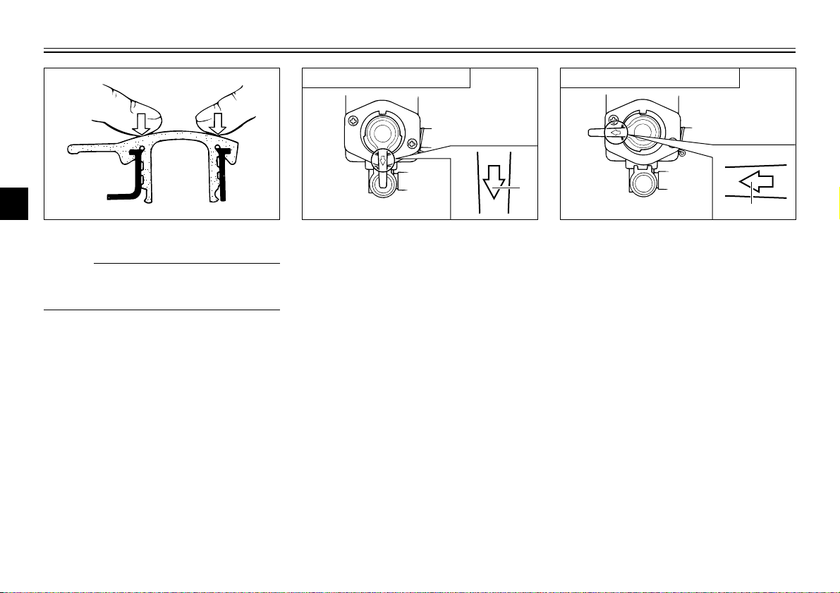
1. Projection
2. Seat holder
To install the seat
1. Insert the projection on the front
of the seat into the seat holder
as shown.
2. Place the seat in the original
position, and then tighten the
bolts.
3. Install the panels.
NOTE:
Make sure that the seat is properly
secured before riding.
3-10
 Loading...