

Page 1
DIGITAL MIXING ENGINE
Owner’s Manual
SCENE NO. CONFIGURATION
XXXXXYAMAHAXDME32
88
48kHz
44.1kHz
LOCK
EMERGENCY
XDigitalX MixingXEngine
COMPONENT PARAMETER
Keep This Manual For Future Reference.
PROTECT
CARD
SCENE
VALUE
UTILITY
USER DEFINE
SCENE RECALLDATA
INC
DEC
7 8 9
4 5 6
1 2
STORE RECALL
3
0
DIGITAL MIXING ENGINE
POWER
ON OFF
E
Page 2

FCC INFORMATION (U.S.A.)
1. IMPORTANT NOTICE: DO NOT MODIFY THIS UNIT! This product, when installed as indicated in the instructions contained in this manual, meets FCC
requirements. Modifications not expressly approved by Yamaha may void your authority, granted by the FCC, to use the product.
2. IMPORTANT: When connecting this product to accessories and/or another product use only high quality shielded cables. Cable/s supplied with this product MUST
be used. Follow all installation instructions. Failure to follow instructions could void your FCC authorization to use this product in the USA.
3. NOTE: This product has been tested and found to comply with the requirements listed in FCC Regulations, Part 15 for Class “B” digital devices. Compliance with
these requirements provides a reasonable level of assurance that your use of this product in a residential environment will not result in harmful interference with
other electronic devices. This equipment generates/uses radio frequencies and, if not installed and used according to the instructions found in the users manual, may
cause interference harmful to the operation of other electronic devices. Compliance with FCC regulations does not guarantee that interference will not occur in all
installations. If this product is found to be the source of interference, which can be determined by turning the unit “OFF” and “ON”, please try to eliminate the
problem by using one of the following measures: Relocate either this product or the device that is being affected by the interference. Utilize power outlets that are on
different branch (circuit breaker or fuse) circuits or install AC line filter/s. In the case of radio or TV interference, relocate/reorient the antenna. If the antenna lead-in
is 300 ohm ribbon lead, change the lead-in to coaxial type cable. If these corrective measures do not produce satisfactory results, please contact the local retailer
authorized to distribute this type of product. If you can not locate the appropriate retailer, please contact Yamaha Corporation of America, Electronic Service
Division, 6600 Orangethorpe Ave, Buena Park, CA 90620
The above statements apply ONLY to those products distributed by Yamaha Corporation of America or its subsidiaries.
WARNING: THIS APPARATUS MUST BE EARTHED
IMPORTANT
THE WIRES IN THIS MAINS LEAD ARE COLOURED IN
ACCORDANCE WITH THE FOLLOWING CODE:
GREEN-AND-YELLOW : EARTH
BLUE : NEUTRAL
BROWN : LIVE
As the colours of the wires in the mains lead of this apparatus may
not correspond with the coloured markings identifying the terminals in
your plug, proceed as follows:
The wire which is coloured GREEN and YELLOW must be
connected to the terminal in the plug which is marked by the letter E
or by the safety earth symbol or coloured GREEN and YELLOW.
The wire which is coloured BLUE must be connected to the terminal
which is marked with the letter N or coloured BLACK.
The wire which is coloured BROWN must be connected to the
terminal which is marked with the letter L or coloured RED.
* This applies only to products distributed by YAMAHA KEMBLE
MUSIC (U.K.) LTD.
NEDERLAND THE NETHERLANDS
● Dit apparaat bevat een lithium batterij voor geheugen
back-up.
ADVARSEL!
Lithiumbatteri—Eksplosionsfare ved fejlagtig
håndtering. Udskiftning må kun ske med batteri
af samme fabrikat og type. Levér det brugte
batteri tilbage til leverandoren.
VARNING
Explosionsfara vid felaktigt batteribyte. Använd
samma batterityp eller en ekvivalent typ som
rekommenderas av apparattillverkaren.
Kassera använt batteri enligt fabrikantens
instruktion.
VAROITUS
Paristo voi räjähtää, jos se on virheellisesti
asennettu. Vaihda paristo ainoastaan
laitevalmistajan suosittelemaan tyyppiin. Hävitä
käytetty paristo valmistajan ohjeiden
mukaisesti.
● This apparatus contains a lithium battery for memory
back-up.
● Raadpleeg uw leverancier over de verwijdering van de
batterij op het moment dat u het apparaat ann het einde
van de levensduur afdankt of de volgende Yamaha Service
Afdeiing:
Yamaha Music Nederland Service Afdeiing
Kanaalweg 18-G, 3526 KL UTRECHT
Tel. 030-2828425
● Gooi de batterij niet weg, maar lever hem in als KCA.
● For the removal of the battery at the moment of the
disposal at the end of the service life please consult your
retailer or Yamaha Service Center as follows:
Yamaha Music Nederland Service Center
Address: Kanaalweg 18-G, 3526 KL
UTRECHT
Tel: 030-2828425
● Do not throw away the battery. Instead, hand it in as small
chemical waste.
Page 3

Important Information
Read the Following Before Using the DME32
Warnings
• Do not subject the DME32 to extreme temperatures, humidity, direct sunlight, or dust,
which could be a potential fire or electrical shock hazard.
• Do not allow water to enter the DME32 or allow it to become wet. Fire or electrical
shock may result.
• Do not place a container with liquid or small metal objects on top of this unit. Liquid
or metal objects inside this unit are a fire and electrical shock hazard.
• Connect the power cord only to an AC outlet of the type stated in this Owner’s Manual
or as marked on the DME32. Failure to do so is a fire and electrical shock hazard.
• Hold the power-cord plug when disconnecting from an AC outlet. Never pull the cord.
A power cord damaged through pulling is a potential fire and electrical shock hazard.
i
• Do not touch the power plug with wet hands. Doing so is a potential electrical shock
hazard.
• Do not place heavy objects, including the DME32, on top of the power cord. A damaged power cord is a fire and electrical shock hazard. In particular, be careful not to
place heavy objects on a power cord covered by a carpet.
• Do not scratch, bend, twist, pull, or heat the power cord. A damaged power cord is a
fire and electrical shock hazard.
• If the power cord is damaged (e.g., cut or a bare wire is exposed), ask your dealer for a
replacement. Using the DME32 with a damaged power cord is a fire and electrical shock
hazard.
• Do not plug several pieces of equipment into the same AC outlet. This may overload
the AC outlet, and could be a fire or electrical shock hazard. It may also affect the performance of some equipment.
• If you notice any abnormality, such as smoke, odor, or noise, or if a foreign object or
liquid gets inside the DME32, turn it off immediately. Remove the power cord from the
AC outlet and consult your dealer for repair. Using the DME32 in this condition is a fire
and electrical shock hazard.
• Do not place small objects on top of the DME32. Metal objects falling inside the
DME32 is a fire and electrical shock hazard.
• If a foreign object or water gets inside the DME32, turn it off immediately. Remove the
power cord from the AC outlet and consult your dealer for repair. Using the DME32 in
this condition is a potential fire and electrical shock hazard.
• Should the DME32 be dropped or the cabinet be damaged, turn off the power, remove
the power plug from the AC outlet, and contact your dealer. If you continue using the
DME32 without heeding this instruction, fire or electrical shock may result.
• Do not remove the DME32’s cover. You could receive an electrical shock. If you think
internal inspection, maintenance, or repair is necessary, contact your dealer.
• Do not attempt to modify the DME32. This is a potential fire and electrical shock hazard.
• Do not block the DME32 ventilation slots. Blocking the ventilation slots is a potential
fire hazard.
DME32—Owner’s Manual
Page 4

ii
Cautions
• Allow enough free space around the DME32 for normal ventilation. This should be
10 cm at the sides, 15 cm behind, and 30 cm above. These distances should also be
adopted when rack-mounting the DME32. For normal ventilation during use, remove
the rear of the rack or open a ventilation hole. If the airflow is not adequate, the DME32
will heat up inside and may cause a fire.
• Use the DME32 in a environment with a free-air temperature of between 10˚C and
35˚C (50˚F and 95˚F).
• Turn off all audio equipment when connecting to the DME32, and use only the cables
specified in the relevant owner’s manuals.
• If you plan not to use the DME32 for a long period of time, remove the power cord from
the AC outlet. Leaving the DME32 connected is a potential fire hazard.
• Do not use benzene, thinner, cleaning detergent, or a chemical cloth to clean the
DME32. Use only a soft, dry cloth.
• If the DME32 is stored in a cold place (e.g., overnight in a car), and then moved to a
warmer environment, or the temperature rises sharply, condensation may form inside
the DME32, which may affect performance. In such cases, the DME32 should be
allowed to acclimatize for about one hour before use.
• When the wordclock source is changed on the wordclock master device (e.g., AD824 or
DME32), noise may occur from the DME32’s analog outputs, especially if an MY8-AT
I/O card is installed, so turn down your power amps, or turn off the DME32 beforehand, otherwise any connected speakers may be damaged.
• If the DME32 displays the message “Warning Low Battery” when it’s turned on, contact
your Yamaha dealer as soon as possible and ask them to replace the internal backup battery. Although the DME32 will continue to work in this condition, any configuration
data will be lost. It’s recommended that you save any configuration data using DME
Manager or a PC Card before replacing the battery.
Interference
The DME32 uses high-frequency digital circuits that may cause interference on radio
and television equipment located nearby. If interference is a problem, relocate the
affected equipment.
DME32 Exclusion of Certain Responsibility
Manufacturer, importer, or dealer shall not be liable for any incidental damages including personal injury or any other damages caused by improper use or operation of the
DME32.
DME32—Owner’s Manual
Page 5

Package Contents
The DME32 package contains the following items. Contact your Yamaha dealer if you
are missing an item.
• DME32 Digital Mixing Engine
• CD-ROM (DME Manager software)
• 9-pin D-sub crossed cable (PC connection)
• 16-pin Euro-block plug (GPI interface)
• Power cord
• This manual
Trademarks
ADAT MultiChannel Optical Digital Interface is a trademark and ADAT and Alesis are
registered trademarks of Alesis Corporation. Intel and Pentium are registered trademarks and MMX is a trademark of Intel Corporation. Tascam Digital Interface is a
trademark and Tascam and Teac are registered trademarks of Teac Corporation. Windows is a trademark of Microsoft Corporation. Yamaha is a trademark of Yamaha Corporation. All other trademarks are the property of their respective holders and are
hereby acknowledged.
iii
Copyright
No part of the DME32 or DME Manager software or this Owner’s Manual may be
reproduced or distributed in any form or by any means without the prior written
authorization of Yamaha Corporation.
© 2000 Yamaha Corporation. All rights reserved.
Yamaha Web Site
Information about the DME32 and other Yamaha professional audio products is available on the Yamaha Professional Audio Web site at:
<http://www.yamaha.co.jp/product/proaudio/homeenglish/>.
DME32—Owner’s Manual
Page 6

Contents v
Contents
1 Welcome . . . . . . . . . . . . . . . . . . . . . . . . . . . . . . . . . 1
Welcome . . . . . . . . . . . . . . . . . . . . . . . . . . . . . . . . . . . . . . . . . . . . . . . . . . . 2
The DME32 in a Nutshell . . . . . . . . . . . . . . . . . . . . . . . . . . . . . . . . . . . . . 2
DME32 Features . . . . . . . . . . . . . . . . . . . . . . . . . . . . . . . . . . . . . . . . . . . . . 4
DME Manager Features . . . . . . . . . . . . . . . . . . . . . . . . . . . . . . . . . . . . . . . 6
About this Manual . . . . . . . . . . . . . . . . . . . . . . . . . . . . . . . . . . . . . . . . . . . 7
Installing the DME32 . . . . . . . . . . . . . . . . . . . . . . . . . . . . . . . . . . . . . . . . . 7
2 Getting Started . . . . . . . . . . . . . . . . . . . . . . . . . . . . 9
First Steps . . . . . . . . . . . . . . . . . . . . . . . . . . . . . . . . . . . . . . . . . . . . . . . . . 10
Connecting to a PC . . . . . . . . . . . . . . . . . . . . . . . . . . . . . . . . . . . . . . . . . 10
Connecting the Power Cord . . . . . . . . . . . . . . . . . . . . . . . . . . . . . . . . . . 11
Turning On & Off the DME32 . . . . . . . . . . . . . . . . . . . . . . . . . . . . . . . . 11
Installing DME Manager . . . . . . . . . . . . . . . . . . . . . . . . . . . . . . . . . . . . . 12
Upgrading & Reinstalling DME Manager . . . . . . . . . . . . . . . . . . . . . . . 12
Starting DME Manager . . . . . . . . . . . . . . . . . . . . . . . . . . . . . . . . . . . . . . 12
Quitting DME Manager . . . . . . . . . . . . . . . . . . . . . . . . . . . . . . . . . . . . . 13
DME Manager & Windows . . . . . . . . . . . . . . . . . . . . . . . . . . . . . . . . . . . 13
Installing the USB Driver . . . . . . . . . . . . . . . . . . . . . . . . . . . . . . . . . . . . 13
Checking the Driver is Installed Correctly . . . . . . . . . . . . . . . . . . . . . . . 14
USB Operating Notes . . . . . . . . . . . . . . . . . . . . . . . . . . . . . . . . . . . . . . . 14
3 Touring the DME32 . . . . . . . . . . . . . . . . . . . . . . . . 15
Front Panel . . . . . . . . . . . . . . . . . . . . . . . . . . . . . . . . . . . . . . . . . . . . . . . . 16
Rear Panel . . . . . . . . . . . . . . . . . . . . . . . . . . . . . . . . . . . . . . . . . . . . . . . . . 19
4 Touring DME Manager . . . . . . . . . . . . . . . . . . . . . 21
Modes . . . . . . . . . . . . . . . . . . . . . . . . . . . . . . . . . . . . . . . . . . . . . . . . . . . . 22
Main Window . . . . . . . . . . . . . . . . . . . . . . . . . . . . . . . . . . . . . . . . . . . . . 23
Configuration Windows . . . . . . . . . . . . . . . . . . . . . . . . . . . . . . . . . . . . . 26
Components . . . . . . . . . . . . . . . . . . . . . . . . . . . . . . . . . . . . . . . . . . . . . . . 30
Component Control Windows . . . . . . . . . . . . . . . . . . . . . . . . . . . . . . . . 31
Run Mode Controller . . . . . . . . . . . . . . . . . . . . . . . . . . . . . . . . . . . . . . . 33
Other Windows . . . . . . . . . . . . . . . . . . . . . . . . . . . . . . . . . . . . . . . . . . . . 33
Touring the Menus . . . . . . . . . . . . . . . . . . . . . . . . . . . . . . . . . . . . . . . . . 34
Component List . . . . . . . . . . . . . . . . . . . . . . . . . . . . . . . . . . . . . . . . . . . . 40
Tool Palette . . . . . . . . . . . . . . . . . . . . . . . . . . . . . . . . . . . . . . . . . . . . . . . . 41
Alt Menu . . . . . . . . . . . . . . . . . . . . . . . . . . . . . . . . . . . . . . . . . . . . . . . . . . 41
Keyboard Shortcuts . . . . . . . . . . . . . . . . . . . . . . . . . . . . . . . . . . . . . . . . . 42
5 Building Configurations . . . . . . . . . . . . . . . . . . . . 43
How to Build & Edit Configurations . . . . . . . . . . . . . . . . . . . . . . . . . . . 44
Selecting Edit Mode . . . . . . . . . . . . . . . . . . . . . . . . . . . . . . . . . . . . . . . . . 45
Opening New Configuration Windows . . . . . . . . . . . . . . . . . . . . . . . . . 45
Opening Saved Configurations . . . . . . . . . . . . . . . . . . . . . . . . . . . . . . . . 46
Selecting Open Configuration Windows . . . . . . . . . . . . . . . . . . . . . . . . 46
Adding Components . . . . . . . . . . . . . . . . . . . . . . . . . . . . . . . . . . . . . . . . 47
DME32—Owner’s Manual
Page 7

vi Contents
6 Running the System . . . . . . . . . . . . . . . . . . . . . . . . 65
Editing Components . . . . . . . . . . . . . . . . . . . . . . . . . . . . . . . . . . . . . . . . 48
Aligning Components to the Grid . . . . . . . . . . . . . . . . . . . . . . . . . . . . . 49
Zooming Configuration Windows . . . . . . . . . . . . . . . . . . . . . . . . . . . . . 50
Selecting Cable Mode . . . . . . . . . . . . . . . . . . . . . . . . . . . . . . . . . . . . . . . 51
Adding Wires . . . . . . . . . . . . . . . . . . . . . . . . . . . . . . . . . . . . . . . . . . . . . . 51
Deleting Wires . . . . . . . . . . . . . . . . . . . . . . . . . . . . . . . . . . . . . . . . . . . . . 56
Working with Multiple-Unit Configurations . . . . . . . . . . . . . . . . . . . . 58
Resizing Sections of the Configuration Window . . . . . . . . . . . . . . . . . 59
Saving Configurations . . . . . . . . . . . . . . . . . . . . . . . . . . . . . . . . . . . . . . . 60
Saving Configurations under a New Name . . . . . . . . . . . . . . . . . . . . . . 60
Closing Configurations . . . . . . . . . . . . . . . . . . . . . . . . . . . . . . . . . . . . . . 60
Compiling Configurations . . . . . . . . . . . . . . . . . . . . . . . . . . . . . . . . . . . 61
Sending Configurations to the DME32 . . . . . . . . . . . . . . . . . . . . . . . . . 62
Receiving Configurations from the DME32 . . . . . . . . . . . . . . . . . . . . . 63
Selecting Run Mode . . . . . . . . . . . . . . . . . . . . . . . . . . . . . . . . . . . . . . . . . 66
Run Mode Controller . . . . . . . . . . . . . . . . . . . . . . . . . . . . . . . . . . . . . . . 67
Editing Component Parameters . . . . . . . . . . . . . . . . . . . . . . . . . . . . . . . 69
Storing Scenes . . . . . . . . . . . . . . . . . . . . . . . . . . . . . . . . . . . . . . . . . . . . . . 70
Recalling Scenes . . . . . . . . . . . . . . . . . . . . . . . . . . . . . . . . . . . . . . . . . . . . 72
Recalling Configurations . . . . . . . . . . . . . . . . . . . . . . . . . . . . . . . . . . . . . 74
7 Other DME Designer Functions . . . . . . . . . . . . . . . 75
Editing Scenes Offline . . . . . . . . . . . . . . . . . . . . . . . . . . . . . . . . . . . . . . . 76
Linking Component Parameters . . . . . . . . . . . . . . . . . . . . . . . . . . . . . . 78
Customizing Component Properties . . . . . . . . . . . . . . . . . . . . . . . . . . . 80
Changing the Size of Rotary Controls & Sliders . . . . . . . . . . . . . . . . . . 82
Using Password Protection . . . . . . . . . . . . . . . . . . . . . . . . . . . . . . . . . . . 83
Assigning the User Define Button . . . . . . . . . . . . . . . . . . . . . . . . . . . . . 86
Printing . . . . . . . . . . . . . . . . . . . . . . . . . . . . . . . . . . . . . . . . . . . . . . . . . . . 87
8 Component Guide Part I . . . . . . . . . . . . . . . . . . . . 89
Automatic Mixer . . . . . . . . . . . . . . . . . . . . . . . . . . . . . . . . . . . . . . . . . . . 90
Cascade . . . . . . . . . . . . . . . . . . . . . . . . . . . . . . . . . . . . . . . . . . . . . . . . . . . 92
Crossover . . . . . . . . . . . . . . . . . . . . . . . . . . . . . . . . . . . . . . . . . . . . . . . . . 93
Crossover Processor . . . . . . . . . . . . . . . . . . . . . . . . . . . . . . . . . . . . . . . . . 102
Delay . . . . . . . . . . . . . . . . . . . . . . . . . . . . . . . . . . . . . . . . . . . . . . . . . . . . . 120
Delayed Mixer . . . . . . . . . . . . . . . . . . . . . . . . . . . . . . . . . . . . . . . . . . . . . 122
Dynamics . . . . . . . . . . . . . . . . . . . . . . . . . . . . . . . . . . . . . . . . . . . . . . . . . 125
9 Component Guide Part II . . . . . . . . . . . . . . . . . . . 141
Effect . . . . . . . . . . . . . . . . . . . . . . . . . . . . . . . . . . . . . . . . . . . . . . . . . . . . . 142
EQ . . . . . . . . . . . . . . . . . . . . . . . . . . . . . . . . . . . . . . . . . . . . . . . . . . . . . . . 162
Fader . . . . . . . . . . . . . . . . . . . . . . . . . . . . . . . . . . . . . . . . . . . . . . . . . . . . . 165
Filter . . . . . . . . . . . . . . . . . . . . . . . . . . . . . . . . . . . . . . . . . . . . . . . . . . . . . 166
Input/Output . . . . . . . . . . . . . . . . . . . . . . . . . . . . . . . . . . . . . . . . . . . . . . 170
Matrix Mixer . . . . . . . . . . . . . . . . . . . . . . . . . . . . . . . . . . . . . . . . . . . . . . 171
Meter . . . . . . . . . . . . . . . . . . . . . . . . . . . . . . . . . . . . . . . . . . . . . . . . . . . . . 174
Misc . . . . . . . . . . . . . . . . . . . . . . . . . . . . . . . . . . . . . . . . . . . . . . . . . . . . . . 175
DME32—Owner’s Manual
Page 8

Contents vii
Pan . . . . . . . . . . . . . . . . . . . . . . . . . . . . . . . . . . . . . . . . . . . . . . . . . . . . . . . 178
Router . . . . . . . . . . . . . . . . . . . . . . . . . . . . . . . . . . . . . . . . . . . . . . . . . . . . 187
Switch . . . . . . . . . . . . . . . . . . . . . . . . . . . . . . . . . . . . . . . . . . . . . . . . . . . . 189
User Control . . . . . . . . . . . . . . . . . . . . . . . . . . . . . . . . . . . . . . . . . . . . . . . 190
User Module . . . . . . . . . . . . . . . . . . . . . . . . . . . . . . . . . . . . . . . . . . . . . . . 193
10 Front Panel Operation . . . . . . . . . . . . . . . . . . . . . . 197
Recalling Configurations . . . . . . . . . . . . . . . . . . . . . . . . . . . . . . . . . . . . . 198
Storing Scenes . . . . . . . . . . . . . . . . . . . . . . . . . . . . . . . . . . . . . . . . . . . . . . 199
Recalling Scenes . . . . . . . . . . . . . . . . . . . . . . . . . . . . . . . . . . . . . . . . . . . . 200
Editing Parameters & the User Define Button . . . . . . . . . . . . . . . . . . . 201
Restricting Access to the DME32 . . . . . . . . . . . . . . . . . . . . . . . . . . . . . . 203
Selecting the Wordclock Source . . . . . . . . . . . . . . . . . . . . . . . . . . . . . . . 209
Checking the I/O Slots . . . . . . . . . . . . . . . . . . . . . . . . . . . . . . . . . . . . . . . 210
Initializing the DME32 . . . . . . . . . . . . . . . . . . . . . . . . . . . . . . . . . . . . . . 210
Checking the Firmware Version & Battery . . . . . . . . . . . . . . . . . . . . . . 210
11 GPI Interface . . . . . . . . . . . . . . . . . . . . . . . . . . . . . 211
About the GPI Interface . . . . . . . . . . . . . . . . . . . . . . . . . . . . . . . . . . . . . 212
GPI Connectors . . . . . . . . . . . . . . . . . . . . . . . . . . . . . . . . . . . . . . . . . . . . 212
Assigning GPI Inputs . . . . . . . . . . . . . . . . . . . . . . . . . . . . . . . . . . . . . . . . 214
Assigning GPI Outputs . . . . . . . . . . . . . . . . . . . . . . . . . . . . . . . . . . . . . . 217
Emergency Mode . . . . . . . . . . . . . . . . . . . . . . . . . . . . . . . . . . . . . . . . . . . 220
12 PC Cards . . . . . . . . . . . . . . . . . . . . . . . . . . . . . . . . 221
PC Cards & the DME32 . . . . . . . . . . . . . . . . . . . . . . . . . . . . . . . . . . . . . 222
Inserting & Ejecting PC Cards . . . . . . . . . . . . . . . . . . . . . . . . . . . . . . . . 222
Formatting PC Cards . . . . . . . . . . . . . . . . . . . . . . . . . . . . . . . . . . . . . . . . 223
Saving Configurations to PC Cards . . . . . . . . . . . . . . . . . . . . . . . . . . . . 224
Loading Configurations from PC Cards . . . . . . . . . . . . . . . . . . . . . . . . 225
Deleting Configurations from PC Cards . . . . . . . . . . . . . . . . . . . . . . . . 226
13 Wordclocks . . . . . . . . . . . . . . . . . . . . . . . . . . . . . . 227
Wordclocks & the DME32 . . . . . . . . . . . . . . . . . . . . . . . . . . . . . . . . . . . 228
Wordclock Connections . . . . . . . . . . . . . . . . . . . . . . . . . . . . . . . . . . . . . 229
Selecting the Wordclock Source . . . . . . . . . . . . . . . . . . . . . . . . . . . . . . . 229
Wordclock Hookup Examples . . . . . . . . . . . . . . . . . . . . . . . . . . . . . . . . 231
Terminating BNC Wordclock Distribution . . . . . . . . . . . . . . . . . . . . . 234
14 Multiple DME32s . . . . . . . . . . . . . . . . . . . . . . . . . . 235
About Multiple DME32s . . . . . . . . . . . . . . . . . . . . . . . . . . . . . . . . . . . . . 236
Multiple-Unit System Notes . . . . . . . . . . . . . . . . . . . . . . . . . . . . . . . . . . 236
Cascade Connections . . . . . . . . . . . . . . . . . . . . . . . . . . . . . . . . . . . . . . . . 237
Multiple-unit Hookup Examples . . . . . . . . . . . . . . . . . . . . . . . . . . . . . . 238
15 MIDI . . . . . . . . . . . . . . . . . . . . . . . . . . . . . . . . . . . . 241
MIDI & the DME32 . . . . . . . . . . . . . . . . . . . . . . . . . . . . . . . . . . . . . . . . . 242
MIDI Ports . . . . . . . . . . . . . . . . . . . . . . . . . . . . . . . . . . . . . . . . . . . . . . . . 242
MIDI Settings . . . . . . . . . . . . . . . . . . . . . . . . . . . . . . . . . . . . . . . . . . . . . . 242
Assigning Scenes & Configurations to Program Changes . . . . . . . . . . 244
Assigning Component Parameters to Control Changes . . . . . . . . . . . 246
DME32—Owner’s Manual
Page 9

viii Contents
16 I/O Options . . . . . . . . . . . . . . . . . . . . . . . . . . . . . . 251
Troubleshooting . . . . . . . . . . . . . . . . . . . . . . . . . . . . . 261
Appendix A: General . . . . . . . . . . . . . . . . . . . . . . . . . 265
Component Parameters & Parameter Changes . . . . . . . . . . . . . . . . . . 248
Saving MIDI Settings . . . . . . . . . . . . . . . . . . . . . . . . . . . . . . . . . . . . . . . . 249
Loading MIDI Settings . . . . . . . . . . . . . . . . . . . . . . . . . . . . . . . . . . . . . . 250
Deleting MIDI Settings . . . . . . . . . . . . . . . . . . . . . . . . . . . . . . . . . . . . . . 250
I/O Options & the DME32 . . . . . . . . . . . . . . . . . . . . . . . . . . . . . . . . . . . 252
I/O Card Specifications . . . . . . . . . . . . . . . . . . . . . . . . . . . . . . . . . . . . . . 253
Choosing I/O Cards . . . . . . . . . . . . . . . . . . . . . . . . . . . . . . . . . . . . . . . . . 253
Installing I/O Cards . . . . . . . . . . . . . . . . . . . . . . . . . . . . . . . . . . . . . . . . . 255
AD824 & DA824 Converters . . . . . . . . . . . . . . . . . . . . . . . . . . . . . . . . . . 256
DME32 . . . . . . . . . . . . . . . . . . . . . . . . . . . . . . . . . . . . . . . . . . . . . . . . . . . 261
DME Manager . . . . . . . . . . . . . . . . . . . . . . . . . . . . . . . . . . . . . . . . . . . . . 263
Component Title Table . . . . . . . . . . . . . . . . . . . . . . . . . . . . . . . . . . . . . . 265
DME32 Error Messages . . . . . . . . . . . . . . . . . . . . . . . . . . . . . . . . . . . . . . 270
DME Manager Error Messages . . . . . . . . . . . . . . . . . . . . . . . . . . . . . . . . 271
Appendix B: Specifications . . . . . . . . . . . . . . . . . . . . . 273
Specifications . . . . . . . . . . . . . . . . . . . . . . . . . . . . . . . . . . . . . . . . . . . . . . 273
Control I/O . . . . . . . . . . . . . . . . . . . . . . . . . . . . . . . . . . . . . . . . . . . . . . . . 274
Connector Pin Assignments . . . . . . . . . . . . . . . . . . . . . . . . . . . . . . . . . . 274
DME32 Dimensions . . . . . . . . . . . . . . . . . . . . . . . . . . . . . . . . . . . . . . . . 277
Appendix C: MIDI . . . . . . . . . . . . . . . . . . . . . . . . . . . . 279
Program Change Assign Table . . . . . . . . . . . . . . . . . . . . . . . . . . . . . . . . 279
Control Change Assign Table . . . . . . . . . . . . . . . . . . . . . . . . . . . . . . . . . 280
MIDI Data Format . . . . . . . . . . . . . . . . . . . . . . . . . . . . . . . . . . . . . . . . . . 283
Glossary . . . . . . . . . . . . . . . . . . . . . . . . . . . . . . . . . . . 287
Index . . . . . . . . . . . . . . . . . . . . . . . . . . . . . . . . . . . . . . 289
MIDI Implementation Chart
DME32—Owner’s Manual
Page 10

In this chapter...
Welcome 1
Welcome
1
Welcome . . . . . . . . . . . . . . . . . . . . . . . . . . . . . . . . . . . . . . . . . . . . . . . . . . . . . . . . . 2
The DME32 in a Nutshell . . . . . . . . . . . . . . . . . . . . . . . . . . . . . . . . . . . . . . . . . . . 2
DME32 Features . . . . . . . . . . . . . . . . . . . . . . . . . . . . . . . . . . . . . . . . . . . . . . . . . . . 4
DME Manager Features . . . . . . . . . . . . . . . . . . . . . . . . . . . . . . . . . . . . . . . . . . . . . 6
About this Manual . . . . . . . . . . . . . . . . . . . . . . . . . . . . . . . . . . . . . . . . . . . . . . . . . 7
Installing the DME32 . . . . . . . . . . . . . . . . . . . . . . . . . . . . . . . . . . . . . . . . . . . . . . . 7
DME32—Owner’s Manual
Page 11
2 Chapter 1—Welcome
Welcome
Thank you for choosing the Yamaha DME32 Digital Mixing Engine.
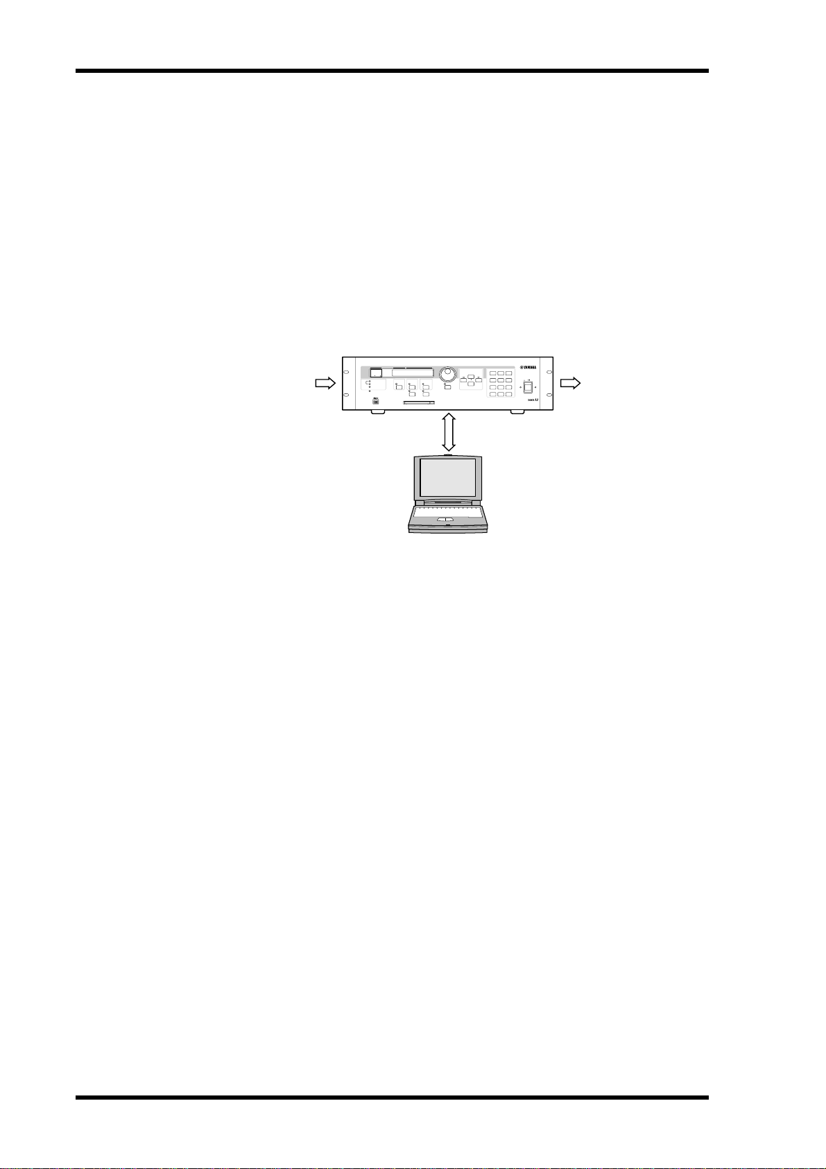
The DME32 Digital Mixing Engine and DME Manager software allow sound-system
installers to custom build systems to meet the specific requirements of almost any
installation. Entire systems from input through to output can be designed using DME
Manager and then transferred to the DME32, which can then be used as a standalone
processor. Typical applications include installed sound systems, submixing, loudspeaker system controllers, matrix/routing, and multi-effects processing.
The DME32 in a Nutshell
SCENE NO. CONFIGURATION
88
48kHz
44.1kHz
LOCK
EMERGENCY
SCENE
XXXXXYAMAHAXDME32
XDigitalXMixingXEngine
COMPONENT PARAMETER
PROTECT
CARD
SCENE RECALLDATA
7 8 9
INC
4 5 6
POWER
VALUE
UTILITY
USER DEFINE
DEC
Control
1 2
0
STORE RECALL
ON OFF
3
DIGITAL MIXING ENGINE
32 outputs32 inputs
DME
Manager
DME32 audio systems, or configurations as they’re known in DME32 terminology, are
built in an intuitive “block diagram” style using Yamaha’s dedicated DME Manager
software. Building configurations consists of adding the necessary components, wiring
them together, compiling, and then transferring that information to the DME32, using
either RS232/RS422, USB (Universal Serial Bus), or PC Cards.
Once programmed, the DME32 operates as a standalone processor and the PC can be
disconnected, although it can be connected permanently in applications where
real-time control from DME Manager is desirable. Even then, if the PC connection is
lost for some reason, the DME32 just keeps on going.
Components form the building blocks in configurations. Some components are complete audio processors, such as mixers, compressors, effects, and crossovers, while others are individual parts, such as faders, switches, pan controls, and meters. System
designers can create their own custom components using the User modules.
DME32—Owner’s Manual
DME Manager operates in one of three modes: Edit, Cable, or Run. Edit mode is used
mainly to build and edit configurations, although it can also be used to edit and preview
scenes offline. Cable mode is for wiring components together. Run mode is used to control the DME32 system in real time, which includes editing component parameters,
storing and recalling scenes, and recalling configurations. In Run mode, actions performed on DME Manager are reflected on the DME32 and vice versa.
The DME32 can store two configurations: A and B. Additional configurations can be
stored on PC Cards. Each configuration can store up to 99 scenes, or snapshots of every
component parameter setting in the configuration. Configurations and scenes can be
recalled from the DME32 front panel, DME Manager, MIDI, or the GPI interface. Configurations and scenes can be titled from the PC keyboard for easy identification.
When operating as a standalone processor, various DME32 functions can controlled
from the front panel, including editing component parameters, storing and recalling
Page 12

The DME32 in a Nutshell 3
scenes, and recalling configurations. Direct access to a specific parameter is possible by
assigning it to the [USER DEFINE] button. The large, two-digit scene number display
indicates the current scene, while the 48-character LCD displays configuration and
scene titles, component and parameter names, parameter values, and so on. Unauthorized operation can be prevented by using the password protection.
The DME32 offers 32 inputs and 32 outputs via four mini YGDAI card slots. Optional
mini YGDAI (Yamaha General Digital Audio Interface) cards offer a variety of analog
and digital I/O configurations, with support for all the popular digital audio interconnect formats, including AES/EBU, ADAT, and Tascam TDIF-1. Inputs and outputs can
be expanded in multiples of 32 by cascading additional DME32s. Up to four DME32s
can be cascaded, providing a maximum of 128 inputs and 128 outputs. Cascade components offer bus-like signal distribution in multiple-unit systems and can also be used
for DSP power sharing between DME32s.
Superb sonic performance is achieved using 32-bit internal signal processing and a
48 kHz internal sampling rate. External sampling rates of between 39.69 kHz to
50.88 kHz are supported and can be set individually for each configuration.
Remote interaction between DME32 functions and custom-made controllers and
other equipment is possible using MIDI and the GPI interface, which offers 16 assignable inputs and 16 assignable outputs. Scenes and configurations can be recalled using
MIDI Program Change messages or the GPI interface. Component parameters can be
controlled by using MIDI Control Change messages, System Exclusive messages, or
custom-made controllers attached to the GPI interface.
See page 4 for a rundown of DME32 features, page 6 for DME Manager features.
DME32—Owner’s Manual
Page 13

4 Chapter 1—Welcome
DME32 Features
Sonic Performance
• 32-bit internal signal processing
• 48 kHz internal sampling rate
• 39.69 kHz to 50.88 kHz external wordclock
Memories & Storage
• 2 configuration memories: A and B
• 99 scene memories per configuration
• Configurations and scenes can be titled from the PC keyboard for easy identification
• Store and transfer configurations on PC Cards
Flexible I/O
• 32 inputs, 32 outputs via four mini YGDAI slots
• Optional mini YGDAI cards offer a variety of analog and digital I/O configurations,
with support for all the popular digital audio interconnect formats, including
AES/EBU, ADAT, and Tascam TDIF-1.
• Analog I/O options include the Yamaha AD824 8-channel 24-bit A/D converter and
DA824 8-channel 24-bit D/A converter
Control Ports
• Switchable RS232/RS422 serial port for PC connection
• RS422 allows cable lengths of up to one kilometer (15 meters for RS232)
• Convenient front panel USB port for PC connection
• COM port for AD824 head-amp gain control
Multiple Units
• Cascade ports for multiple-unit operation with up to four DME32s
• I/O expansion in multiples of 32, with a maximum of four DME32s providing 128
inputs and 128 outputs
• 32 cascade buses allow bus-like signal distribution and power sharing between DME32s
Remote Control
• Configuration and scene recall using MIDI Program Changes
• Component parameter control using MIDI Control Changes or System Exclusive
• GPI interface with 16 assignable inputs, 16 assignable outputs
• Emergency mode assignable to any GPI input
DME32—Owner’s Manual
Page 14

DME32 Features 5
Standalone Operation
• DME Manager can be disconnected once the DME32 has been programmed
• Dedicated keypad for scene store and recall
• Data wheel and INC/DEC buttons for component parameter editing
• Assignable [USER DEFINE] button for quick parameter access
Others
• Large, 2-digit scene number indicator
• 48-character LCD display
• Password protection prevents unauthorized operation
• Wordclock I/O and switchable termination for master/slave operation
• 3U rack space
DME32—Owner’s Manual
Page 15

6 Chapter 1—Welcome
DME Manager Features
Components
• Processor components include crossovers, dynamics, filters, GEQ, PEQ, effects, etc
• Part-type components include faders, meters, switches, pan controls, etc
• Create custom components using User Modules
• Copy frequently used controls to custom control windows
• Customize the size of rotary controls and sliders
Edit mode
• Drag and drop components onto configuration windows
• Use standard cut, copy, and paste commands to edit components
• Customize component appearance, including title, size, and color
• DSP power meter indicates approximate processor usage
• Align and snap components to the variable grid
• Zoom in to see components in detail or zoom out to see more of a configuration
Cable Mode
• Wire components by dragging wires between input and output nodes
• Wire component nodes individually or in multiples
Run mode
• Real-time control using DME Manager
• Edit component parameters, recall and store scenes, and recall configurations
• Actions performed on DME Manager are reflected on the DME32 and vice versa
Offline Operation
• Build and edit configurations off-site
• Edit, title, and delete scenes offline
• Preview scenes offline
Configurations & Scenes
• Title configurations and scenes from the PC keyboard
• Save configurations to any media available to Windows, including PC Cards
• Open multiple configurations simultaneously
• Drag rotary controls and sliders
• Set PEQ parameters by dragging points on an EQ curve
• Context-sensitive shortcut menu containing frequently used commands
• Floating tool palette and Alt-click mode menu for quick mode switching
DME32—Owner’s Manual
Easy Operation
Page 16

About this Manual 7
Other Features
• Up to 32 parameter-link groups for fader grouping, stereo signal control, or crossover
frequency control in multiple-speaker systems
• Link parameters across cascaded DME32s
• 3-level password protection allows full access, limited access, or no access
• Print configuration information, including diagrams, component and parameter lists
About this Manual
This Owner’s Manual contains all the information you need in order to operate the
DME32 Digital Mixing Engine and DME Manager. Use the table of contents to familiarize yourself with the organization of this manual and locate topics. Use the index to
locate specific information. A glossary of DME32-related jargon is provided on
page 287.
In this manual, the DME32 Digital Mixing Engine and DME Manager software are
referred to as the “DME32” and “DME Manager” respectively. “PC” refers to an IBM
PC-compatible computer running a Windows operating system.
Installing the DME32
When mounting the DME32 in a rack, remove the DME32’s feet and leave adequate
ventilation space around the DME32 (at least 15 cm of free space behind). If the
DME32 is mounted in a portable rack case, keep the rear of the case open when using
the DME32 so as not to obstruct the free flow of air. Do not mount the DME32 above
equipment that produces a lot of heat, such as a power amplifier.
DME32—Owner’s Manual
Page 17

In this chapter...
Getting Started 9
Getting Started
2
First Steps . . . . . . . . . . . . . . . . . . . . . . . . . . . . . . . . . . . . . . . . . . . . . . . . . . . . . . . . 10
Connecting to a PC . . . . . . . . . . . . . . . . . . . . . . . . . . . . . . . . . . . . . . . . . . . . . . . 10
Connecting the Power Cord . . . . . . . . . . . . . . . . . . . . . . . . . . . . . . . . . . . . . . . . 11
Turning On & Off the DME32 . . . . . . . . . . . . . . . . . . . . . . . . . . . . . . . . . . . . . . 11
Installing DME Manager . . . . . . . . . . . . . . . . . . . . . . . . . . . . . . . . . . . . . . . . . . . 12
Upgrading & Reinstalling DME Manager . . . . . . . . . . . . . . . . . . . . . . . . . . . . . 12
Starting DME Manager . . . . . . . . . . . . . . . . . . . . . . . . . . . . . . . . . . . . . . . . . . . . 12
Quitting DME Manager . . . . . . . . . . . . . . . . . . . . . . . . . . . . . . . . . . . . . . . . . . . . 13
DME Manager & Windows . . . . . . . . . . . . . . . . . . . . . . . . . . . . . . . . . . . . . . . . . 13
Installing the USB Driver . . . . . . . . . . . . . . . . . . . . . . . . . . . . . . . . . . . . . . . . . . . 13
Checking the Driver is Installed Correctly . . . . . . . . . . . . . . . . . . . . . . . . . . . . . 14
USB Operating Notes . . . . . . . . . . . . . . . . . . . . . . . . . . . . . . . . . . . . . . . . . . . . . . 14
DME32—Owner’s Manual
Page 18

10 Chapter 2—Getting Started
PC CONTROL
RS
232CRS422
First Steps
Here’s how to get up and running with the DME32 system with the minimum of fuss.
1 Familiarize yourself with the DME32.
See “Touring the DME32” on page 15.
2 Install the required mini YGDAI I/O cards.
See “I/O Options” on page 251.
3 Connect your audio sources and other equipment to the inputs and outputs.
4 Connect the DME32 to your PC.
See “Connecting to a PC” on page 10.
5 Connect the power cord and turn on the DME32.
See “Connecting the Power Cord” on page 11 and “Turning On & Off the DME32” on
page 11.
6 Install DME Manager.
See “Installing DME Manager” on page 12.
7 Start DME Manager.
See “Starting DME Manager” on page 12.
8 Familiarize yourself with DME Manager.
See “Touring DME Manager” on page 21.
9 Build a configuration.
See “Building Configurations” on page 43.
10 Compile the configuration.
See “Compiling Configurations” on page 61.
11 Transfer the configuration to the DME32.
See “Sending Configurations to the DME32” on page 62.
12 Take the configuration for a run.
See “Running the System” on page 65.
Connecting to a PC
The DME32 can be connected to a PC by using standard RS232/RS422 serial connections or
USB (Universal Serial Bus). When the DME32 receives a command via the serial port, it
transmits a response to only the serial port. Likewise, when it receives a command via the
USB port, it transmits a response to only the USB port.
Serial Port
The PC CONTROL port features a switch for selecting
RS232 or RS422. These two serial port standards are virtually the same, the main difference being that RS422 is balanced and therefore supports longer cable lengths. RS232
supports cable lengths of up to 15 meters, while RS422 supports lengths of up to 1 kilometer. Select the one that
matches your PC’s serial port.
Serial cable
WORD CLOCK
IN
OUT OUT IN
75Ω
OFFON
12345678
IN +V
AC IN
OUTGND
IN +V
GND
OUT
4
SLOT
12345678
910111213141516
2
SLOT
910111213141516
PC CONTROL port
RS
232CRS422
CASCADE INCASCADE OUTCOMPC CONTROLMIDI
3
SLOT
1
SLOT
COM port
DME32—Owner’s Manual
Page 19

Connecting the Power Cord 11
You can specify which COM port on your PC DME Manager uses, although you’ll need to
install DME Manager in order to do this. See “Installing DME Manager” on page 12 for more
information. Using a text editor, open the “setup.ini” file in the DME folder. Change the COM
parameter to match the number of the COM port you want to use. To use COM port 2, for
example, the setting should be “COM2” (without quotation marks).
USB
Important: You need to install the USB driver in order to use the USB port. See page 13.
The front panel USB port is a convenient way to connect a PC to the DME32 and
is ideal for systems where the DME32 rear panel is not easily accessible.
SCENE NO. CONFIGURATION
88
48kHz
44.1kHz
LOCK
EMERGENCY
SCENE
XXXXXYAMAHAXDME32
XDigitalXMixingXEngine
COMPONENT PARAMETER
PROTECT
CARD
SCENE RECALLDATA
7 8 9
INC
4 5 6
POWER
VALUE
UTILITY
USER DEFINE
DEC
ON OFF
1 2
3
0STORE RECALL
DIGITAL MIXING ENGINE
USB port
USB port
USB cable
Connecting the Power Cord
Warning: Turn off all equipment before making any power connections.
Connect the socket-end of the supplied power cord to the AC IN socket on
the rear panel of the DME32. Connect the plug-end to a suitable AC wall outlet, one that conforms to the power supply requirements stated on the
DME32 rear panel.
Turning On & Off the DME32
To prevent loud clicks and thumps in your speakers, turn on your audio
equipment in the following order (reverse this order when turning off
your equipment)—sound sources, mixer or recorder (e.g., 02R, DME32,
D24, etc.), power amplifiers.
AC IN
POWER
ON OFF
1 To turn on the DME32, press the [POWER] switch.
The following message appears for a few moments.
XXXXXYAMAHAXDME32
XDigitalXMixingXEngine
The number and title of the current configuration and scene appear on the display. The first
parameter of the first component is selected, unless the [USER DEFINE] button has been
assigned, in which case, the parameter assigned to that button is selected and the USER
DEFINE indicator lights up.
When the DME32 is turned on for the first time, or when it’s initialized, configuration mem-
ory A contains a simple configuration titled “Mtrx16.” This configuration is stored inside the
DME32 and can be overwritten by transferring another configuration from DME Manager.
2 To turn off the DME32, press the [POWER] switch.
DME32—Owner’s Manual
Page 20

12 Chapter 2—Getting Started
Installing DME Manager
System Requirements
• A computer with a 200 MHz or faster Intel Pentium MMX processor or equivalent
• At least 32 MB of RAM (64 MB or more recommended)
• A hard disk with at least 20 MB of free space
• A CD-ROM or DVD-ROM drive (installation only)
• A VGA or better display (640 x 480, 256 color minimum)
• An RS232 or RS422 serial port or a USB port
• Windows 95/98
Installing DME Manager
Before installing DME Manager, make sure that your PC meets the system requirements
listed previously.
1 Turn on your PC and, if it’s not running already, start Windows.
The PC does not need to be connected to the DME32 in order to install DME Manager.
2 Insert the DME32 CD-ROM disc into your CD-ROM or DVD-ROM drive.
If the Windows CD-ROM Autorun feature is turned on, the installation start up screen
appears automatically.
3 Continue with the installation as prompted.
If the Windows CD-ROM Autorun feature is not turned on, you must start the installation
manually, as explained below.
4 Double-click the My Computer icon.
The My Computer window opens.
5 Double-click the “DME32” CD-ROM icon.
The installation start up screen appears.
6 Continue with the installation as prompted.
When the installation process is complete, remove the CD-ROM disc from the CD-ROM
drive and return it to its case for safe keeping.
The installation program adds a DME item to the Windows Programs menu.
Upgrading & Reinstalling DME Manager
1 Use the “Add/Remove Programs” control panel to remove DME Manager.
2 Locate the “DME” folder and delete all the files inside it (do not delete the
Starting DME Manager
1 Click the Windows “Start” button and select Programs, DME.
DME32—Owner’s Manual
Before upgrading or reinstalling DME Manager, you must delete the previously installed version as follows.
“AddIn,” “Midi,” or “Module” folders or the files inside them).
Normally the “DME” folder is in “C:\Program Files.”
DME Manager starts.
When DME Manager is started, it checks whether any active DME32s are connected, active
meaning connected and turned on. If an active DME32 containing configuration data is
detected, a message asking whether or not you want to receive the configuration data
appears. If you choose to receive it, all the configuration data in the DME32 is transferred to
DME Manager and displayed in new configuration windows, and DME Manager switches to
Page 21

Quitting DME Manager 13
Run mode. (See page 65 for more information on Run mode.) If you choose not to receive
it, DME Manager starts up in Edit mode.
If no DME32s are detected, the message “DME32 not found!” appears. In this case you can
click OK to continue using DME Manager offline in Edit mode. If a DME32 becomes avail-
able after DME Manager was started, a message asking whether or not you want to receive
the configuration data appears. If you choose to receive it, all the configuration data in the
DME32 is transferred to DME Manager and displayed in new configuration windows, and
DME Manager switches to Run mode. See page 65 for more information on Run mode. (See
page 65 for more information on Run mode.) If you choose not to receive the data, DME
Manager continues in Edit mode.
Configuration data can be received from the DME32 by using the Data Transfer window. See
“Receiving Configurations from the DME32” on page 63 for more information.
Quitting DME Manager
1 Choose Exit from the File menu.
If no configuration windows contain unsaved changes, all configuration windows close and
DME Manager quits.
If a configuration window contains any unsaved changes, a message asking if you would like
to save the changes appears. Click OK to save the changes and quit, or click Cancel to cancel
the operation.
DME Manager can also be quit by clicking the Close button in the upper-right corner
of the main window.
DME Manager & Windows
When using DME Manager with Windows 98, component control-window movement may
be a little erratic. To resolve this problem, in Windows 98, open the Display control panel and
click the Effects tab, and then turn off the “Show window contents while dragging” option.
If components and wires are displayed out of alignment, you can resolve the problem as follows: in Windows 98, open the Display control panel, click the Settings tab, and then click
Advanced. Click the General tab, and then set the Display Font Size to“Small Fonts.” If you
are using Windows 95, open the Display control panel, click the Settings tab, and then set
Font to “Small Fonts.”You may be prompted to restart your PC.
Installing the USB Driver
In order to use the USB port, you must install the USB driver as follows. For this you’ll need
your DME32 CD-ROM, and you may be prompted to insert your Windows CD-ROM during installation, so keep it handy.
1 Turn on your PC.
2 With the DME32 turned off, connect it to your PC using the USB cable.
3 Turn on the DME32.
After a few moments, the Add New Hardware Wizard appears. (If it doesn’t appear, try dis-
connecting and reconnecting the USB cable.)
4 Click Next.
The next window asks “What do you want Windows to do?”
5 Select the “Search for the best driver for your device. (Recommended).” option,
and then click Next.
The next window asks you to specify the driver location.
6 Insert the DME32 CD-ROM into your CD-ROM/DVD drive.
7 Select “Specify a location” (unselect the other options), and then click Browse.
DME32—Owner’s Manual
Page 22
14 Chapter 2—Getting Started
8 In the Browse for Folder window, select the “USBdrv_” folder on the DME32
CD-ROM, and then click OK.
9 Click Next.
The next window tells you that Windows has detected the driver and is now ready to install
it. Make sure that the device is stated as “YAMAHA USB MIDI Driver.”
10 Click Next.
Windows installs the driver.
When the installation is complete, the “Windows has finished...” window appears.
11 Click Finish.
Installation is complete.
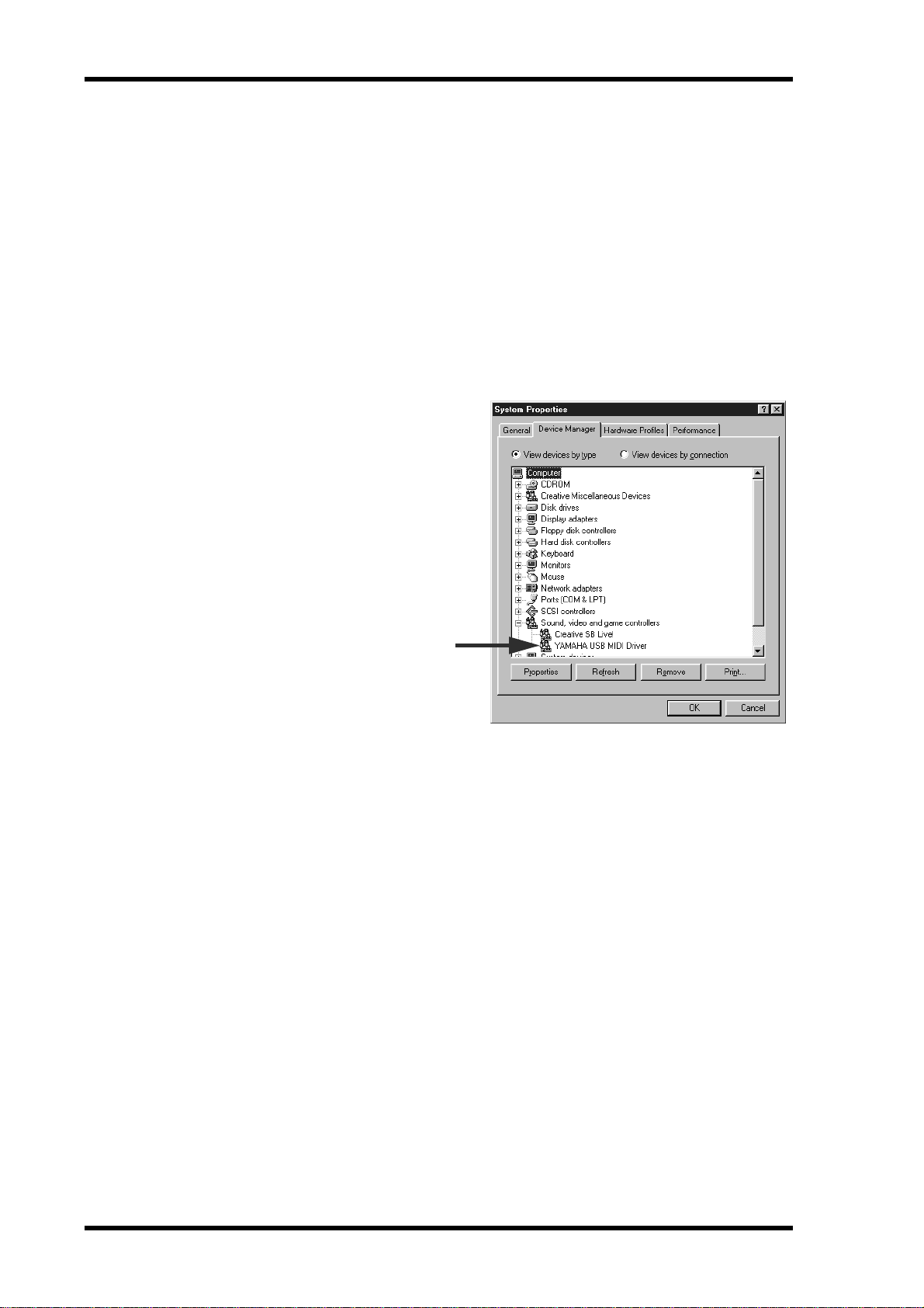
Checking the Driver is Installed Correctly
Follow the steps below to make
sure that the driver has been
installed correctly.
1 Right-click the My Computer
icon and choose Properties.
The System Properties window
appears.
2 Click the Device Manager tab.
The device list appears.
3 Check to see if “YAMAHA USB
MIDI Driver” appears in the
list, as shown right. If it does,
the driver is installed correctly.
4 Click Cancel to close the Prop-
erties window.
USB Operating Notes
If you turn on or off the power to the DME32, or connect or disconnect the USB cable under
the following conditions, your computer may freeze, or some of the DME32 functions may
be disabled:
• While the DME32 is being detected by Windows or its driver is being loaded.
• While Windows is starting or shutting down.
• When your computer is in standby mode.
• While an audio or MIDI program is starting.
In addition, the following may cause your computer to freeze or disable some DME32 functions:
• Turning the power on or off, or repeatedly connecting and disconnecting the USB
cable.
• Entering or leaving standby mode during an audio or MIDI data transfer.
• Connecting or disconnecting the USB cable while the DME32 is turned on.
• Turning the power to the DME32 on or off, starting your computer, or installing the
driver while a large amount of data is being transferred.
If you cannot shutdown Windows, try disconnecting the USB cable from the DME32.
If you cannot start Windows, turn off your computer, disconnect the USB cable, turn your
computer on again, and then reconnect the USB cable.
DME32—Owner’s Manual
Page 23

In this chapter...
Touring the DME32 15
Touring the DME32
3
Front Panel . . . . . . . . . . . . . . . . . . . . . . . . . . . . . . . . . . . . . . . . . . . . . . . . . . . . . . 16
Rear Panel . . . . . . . . . . . . . . . . . . . . . . . . . . . . . . . . . . . . . . . . . . . . . . . . . . . . . . . 19
DME32—Owner’s Manual
Page 24

16 Chapter 3—Touring the DME32
XXX
XAX
Front Panel
4 5 76 81
USER DEFINE
SCENE RECALLDATA
INC
DEC
7 8 9
4 5 6
1 2
0STORE RECALL
3
DIGITAL MIXING ENGINE
SCENE NO. CONFIGURATION
XXXXXYAMAHAXDME32
88
48kHz
44.1kHz
LOCK
EMERGENCY
XDigitalX MixingXEngine
COMPONENT PARAMETER
32
PROTECT
SCENE
VALUE
UTILITY
CARD
L P Q U VON S TM RKJ9
A SCENE NO. indicator
This 2-digit display shows the number of the current scene memory. The number
flashes when a different scene memory is selected and stops flashing if that scene memory is recalled or stored.
B Scene edit dots
These two dots indicate whether or not the current settings match those of the last
recalled scene memory. When a scene is recalled, both indicators go out. If a parameter
is edited, they both light up, indicating that a parameter has been edited since the last
scene was recalled.
POWER
ON OFF
C Display
This 48-character LCD display shows information such as configuration and scene
titles, component and parameter names, parameter values, functions, messages, and so
on. It’s divided into five sections—CONFIGURATION, SCENE, COMPONENT,
PARAMETER, and VALUE—as shown in the following example.
CONFIGURATION SCENE
SetupX
OscillaXXWaveforXXX
COMPONENT PARAMETER
DefaultXXScene
100Hz
VALUE
D DATA wheel
This wheel is used for selecting configurations, components, parameters, setting values,
and making other settings. Turn it clockwise to increase a value; counterclockwise to
decrease it.
DME32—Owner’s Manual
Page 25

Front Panel 17
E INC & DEC buttons
These buttons work in parallel with the DATA wheel and are used when selecting configurations, components, parameters, setting values, or making other settings. Use the
[INC] button to increase a value; the [DEC] button to decrease it.
F STORE button
This button is used to store scenes. See “Storing Scenes” on page 199 for more informa-
tion.
G SCENE RECALL number keypad
The number keypad is used to enter scene memory numbers from 1 to 99.
H RECALL button
This button is used to recall scenes. See “Recalling Scenes” on page 200 for more infor-
mation.
I 48kHz & 44.1kHz indicators
These indicators show the selected wordclock frequency: 48 kHz or 44.1 kHz. See
“Selecting the Wordclock Source” on page 229 for more information.
J LOCK indicator
This indicator shows whether or not the DME32 is wordclock locked to the selected
wordclock source. It lights up when the DME32 is wordclock locked. See “Selecting the
Wordclock Source” on page 229 for more information.
K EMERGENCY indicator
This indicator lights up when the GPI input assigned to Emergency is activated. In
Emergency mode, the DME32 mutes all outputs until the emergency condition is
removed. See “Emergency Mode” on page 220 for more information.
L USB port
This USB port is used to connect the DME32 to a Windows PC and provides a convenient alternative to the PC CONTROL port on the rear panel. See “Connecting to a PC”
on page 10 for more information.
M COMPONENT button & indicator
This button is used to select the COMPONENT section of the display. When pressed,
the cursor moves to the COMPONENT section of the display and the COMPONENT
indicator lights up. It’s also used with the utility functions.
This button can also be used to view a component’s full title on the DME32 display.
Normally only the first seven characters of a component’s title are displayed. Pressing
the [COMPONENT] button displays the full title by using the PARAMETER section of
the display. Pressing the button again returns to the normal display.
N PARAMETER button & indicator
This button is used to select the PARAMETER section of the display. When pressed, the
cursor moves to the PARAMETER section of the display and the PARAMETER indicator lights up. It’s also used with the utility and protection functions.
O PROTECT button & indicator
This button is used in conjunction with the protection functions, which can be used to
restrict access to the DME32. The PROTECT indicator lights up when the [PROTECT]
button is pressed. See “Restricting Access to the DME32” on page 203 for more infor-
mation.
P CARD slot
Optional PC Card memory cards are inserted here for additional configuration and
scene storage. See “PC Cards” on page 221 for more information.
DME32—Owner’s Manual
Page 26

18 Chapter 3—Touring the DME32
Q CARD eject button
This button is used to eject PC Cards. See “Inserting & Ejecting PC Cards” on page 222
for more information.
R UTILITY button & indicator
This button is used to access the utility functions. The UTILITY indicator lights up
when the [UTILITY] button is pressed.
S VALUE button & indicator
This button is used to select the VALUE section of the display. When pressed, the cursor
moves to the VALUE section of the display and the VALUE indicator lights up.
T USER DEFINE button & indicator
This button can provide direct access to a specified parameter. The USER DEFINE indicator lights up when the [USER DEFINE] button is pressed. See “Editing Parameters &
the User Define Button” on page 201 for more information.
U Cursor buttons ( / )
These buttons are used to move the cursor around the display. The left ( ) cursor button moves the cursor to the left; the right ( ) cursor button moves it to the right.
V POWER switch
This switch is used to turn on the power to the DME32. See “Turning On & Off the
DME32” on page 11 for more information.
There are two M3 screw holes above and below the POWER switch, 34 mm apart, for
attaching a protective cover. Yamaha does not offer such a cover, so it must be sourced
by the user.
DME32—Owner’s Manual
Page 27
Rear Panel
MLK
J986 752 41 3
910111213141516
910111213141516
12345678
12345678
SLOT
2
SLOT
4
SLOT
1
SLOT
3
CASCADE INCASCADE OUTCOMPC CONTROLMIDI
AC IN
WORD CLOCK
IN
OFFON
75Ω
OUT OUT IN
IN +V
OUT GND
GND
IN +V
OUT
RS
232CRS422
Rear Panel 19
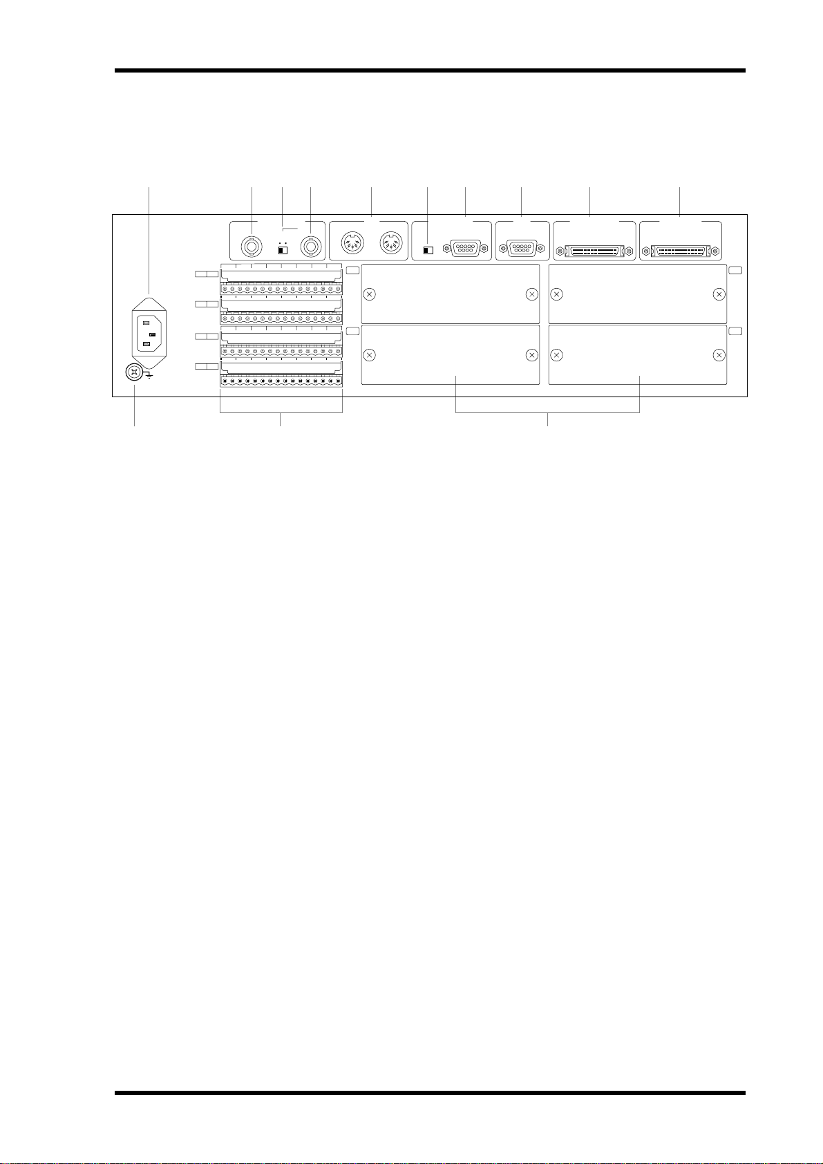
A AC IN connector
B WORD CLOCK OUT connector
C WORD CLOCK 75Ω ON/OFF switch
D WORD CLOCK IN connector
E MIDI IN & OUT ports
F PC CONTROL RS232C/RS422 switch
G PC CONTROL port
H COM port
This connector is used to connect the DME32 to an AC outlet, using the supplied power
cord. See “Connecting the Power Cord” on page 11 for more information.
This BNC connector transmits the internally generated wordclock signal or the wordclock signal received at the WORD CLOCK IN when an external wordclock source is
selected. See “Wordclock Connections” on page 229 for more information.
This switch is used to terminate the wordclock signal received at the WORD CLOCK
IN. See “Wordclock Connections” on page 229 for more information.
This BNC connector can be used to receive an external wordclock signal. See “Wo r d -
clock Connections” on page 229 for more information.
These are standard MIDI IN and OUT ports and are used to connect the DME32 with
other MIDI equipment for remote operation using MIDI Program Change, Control
Change, and Parameter Change messages. See “MIDI & the DME32” on page 242 for
more information.
This switch is used to select the format for the PC CONTROL port. See “Connecting to
a PC” on page 10 for more information.
This 9-pin D-sub connector is used to connect the DME32 to the serial port on a Windows PC. See “Connecting to a PC” on page 10 for more information.
This 9-pin D-sub connector is used to connect the DME32 to a Yamaha AD824 AD
Converter. See “AD824 & DA824 Converters” on page 256 for more information.
DME32—Owner’s Manual
Page 28

20 Chapter 3—Touring the DME32
I CASCADE OUT port
This 50-pin half-pitch connector is used to cascade DME32s in a multiple-unit system.
See “About Multiple DME32s” on page 236 for more information.
J CASCADE IN port
This 50-pin half-pitch connector is used to cascade DME32s in a multiple-unit system.
See “About Multiple DME32s” on page 236 for more information.
K Ground terminal
For safety reasons it is important that the DME32 is grounded. The supplied power
cord has a three-pin plug, and if the ground terminal of the AC outlet is grounded, then
the DME32 will be grounded adequately via the power cord. If the AC outlet does not
have a suitable ground terminal, a ground connection should be made to this ground
terminal. Grounding is also an effective method for preventing hum, interference, and
other noise.
L GPI connectors
These four Euro-block connectors make up the DME32’s GPI (General Purpose Interface), which allows interaction and remote control of DME32 functions using custom-made controllers and other equipment. See “GPI Interface” on page 211 for more
information.
M SLOTs 1–4
These four slots are for use with optional mini YGDAI cards, which offer a variety of
analog and digital I/O options. See “I/O Options” on page 251 for more information.
DME32—Owner’s Manual
Page 29

In this chapter...
Touring DME Manager 21
Touring DME Manager
4
Modes . . . . . . . . . . . . . . . . . . . . . . . . . . . . . . . . . . . . . . . . . . . . . . . . . . . . . . . . . . . 22
Main Window . . . . . . . . . . . . . . . . . . . . . . . . . . . . . . . . . . . . . . . . . . . . . . . . . . . . 23
Configuration Windows . . . . . . . . . . . . . . . . . . . . . . . . . . . . . . . . . . . . . . . . . . . 26
Components . . . . . . . . . . . . . . . . . . . . . . . . . . . . . . . . . . . . . . . . . . . . . . . . . . . . . 30
Component Control Windows . . . . . . . . . . . . . . . . . . . . . . . . . . . . . . . . . . . . . . 31
Run Mode Controller . . . . . . . . . . . . . . . . . . . . . . . . . . . . . . . . . . . . . . . . . . . . . . 33
Other Windows . . . . . . . . . . . . . . . . . . . . . . . . . . . . . . . . . . . . . . . . . . . . . . . . . . . 33
Touring the Menus . . . . . . . . . . . . . . . . . . . . . . . . . . . . . . . . . . . . . . . . . . . . . . . . 34
Component List . . . . . . . . . . . . . . . . . . . . . . . . . . . . . . . . . . . . . . . . . . . . . . . . . . 40
Tool Palette . . . . . . . . . . . . . . . . . . . . . . . . . . . . . . . . . . . . . . . . . . . . . . . . . . . . . . 41
Alt Menu . . . . . . . . . . . . . . . . . . . . . . . . . . . . . . . . . . . . . . . . . . . . . . . . . . . . . . . . 41
Keyboard Shortcuts . . . . . . . . . . . . . . . . . . . . . . . . . . . . . . . . . . . . . . . . . . . . . . . 42
DME32—Owner’s Manual
Page 30

22 Chapter 4—Touring DME Manager
Modes
DME Manager has three operating modes: Edit, Cable, and Run. These can be selected
from the Mode menu (see page 35), Shortcut menu (see page 39), Tool Bar (see
page 24), Tool Palette (see page 41), or Alt menu (see page 41). The currently selected
mode is displayed in the status bar. See “Status bar” on page 25 for more information.
Edit Mode
Edit mode is used to build and edit configurations. It can also be used to edit scenes
offline.
See “Building Configurations” on page 43 for more information.
Cable Mode
Cable mode is used to wire components together.
See “Adding Wires” on page 51 for more information.
Run Mode
Run mode is used to control the DME32 system in real time, which includes editing
component parameters, storing and recalling scenes, and recalling configurations. In
Run mode, actions performed on DME Manager are reflected on the DME32 and vice
versa. Components and wires cannot be edited in this mode.
See “Running the System” on page 65 for more information.
Configurations can be compiled and configuration data can be transferred between the
DME32 and DME Manager in either Edit or Cable mode.
DME32—Owner’s Manual
Page 31

Main Window 23
Main Window
This is the main window in which configuration windows are managed. Normally you
won’t see this window appear like this because DME Manager always starts with a configuration window open, be it a new window or a window containing the configuration
received from the DME32. If you close all configuration windows, however, you’ll see
the main window appear like this.
The main window can be minimized, maximized, and restored to its previous size by
clicking the standard Windows buttons in the upper-right corner. Clicking the Close
button quits DME Manager. The main window can be resized by dragging the
lower-right corner. It can also be controlled using the commands in the control menu,
which is accessed by clicking the program icon in the upper-left corner.
Title Bar
The main window title bar displays information about the current configuration win-
dow, including configuration title and current scene number and title.
When no configuration windows are open, the title bar appears as follows.
When an unsaved configuration window is selected, the title bar appears as follows.
When the window for a configuration stored in the DME32 is selected, the configura-
tion title is prefixed with the letter “A” or “B,” as shown below.
When the window for the currently running configuration is selected, the configura-
tion title is prefixed with the word “Running,” as shown below.
Note that when a configuration window is not at full size, the configuration and scene
information shown in the above examples appears in the title bar of the configuration
window, not the main window.
DME32—Owner’s Manual
Page 32

24 Chapter 4—Touring DME Manager
Tool Bar
The Tool Bar provides convenient access to the Run, Edit, and Cable modes and the
Compile, Zoom, and Align functions.
1 2 3 4 5 6
A Run mode
This button selects Run mode. See “Run Mode” on page 22 for more information.
B Edit mode
This button selects Edit mode. See “Edit Mode” on page 22 for more information.
C Cable mode
This button selects Cable mode. See “Cable Mode” on page 22 for more information.
D Compile
This button compiles the current configuration. See “Compiling Configurations” on
page 61 for more information.
E Zoom
This button cycles through the Zoom settings: 25%, 50%, 75%, 100%, 150%. See
“Zooming Configuration Windows” on page 50 for more information.
F Align
This button aligns all components to the grid. See “Aligning Components to the Grid”
on page 49 for more information.
DME32—Owner’s Manual
Page 33

Main Window 25
Status bar
The status bar displays the current mode, the title of the current component, the compilation status, and the protection status.
1 2 3 4 5
A Selected Mode
This section displays the currently selected mode: Edit, Cable, or Run. See “Modes” on
page 22 for more information.
B Selected Component
This section displays the title of the currently selected component.
C Compilation Status
This section displays the compilation status of the current configuration: Uncompiled,
Compiled, or Compile Failure. See “Compiling Configurations” on page 61 for more
information.
D Protection Status
This section displays the protection status of the current configuration: Off, Component, or Operation. See “Using Password Protection” on page 83 for more information.
E DME32 Status
This section displays which configuration is currently selected on the DME32: “Config
A” or “Config B.” If no DME32 is available, “Offline” appears.
DME32—Owner’s Manual
Page 34

26 Chapter 4—Touring DME Manager
Configuration Windows
Configurations are built, wired, and controlled in configuration windows. See “How to
Build & Edit Configurations” on page 44 for more information.
The following configuration window shows an example configuration.
Configuration windows can be minimized, maximized, and restored to their previous
size by clicking the buttons in the upper-right corner of the configuration window.
Clicking the Close button closes the configuration window. Configuration windows
can be resized by dragging the lower-right corner. They can also be scrolled using the
horizontal and vertical scroll bars. Windows can also be controlled using the commands in the control menu, which is accessed by clicking the program icon in the
upper-left corner of the configuration window.
DME32—Owner’s Manual
Page 35

Configuration Windows 27
Minimized configuration windows appear along the bottom of the main window, as
shown below.
Use the Restore and Maximize buttons to enlarge minimized configuration windows,
or use the commands in the control menu, which is accessed by clicking anywhere on
the configuration window’s title bar, as shown below.
DSP Power Meter
The DSP power meter displays the approximate amount of DSP processing
power used by the configuration. There is one meter in each section of the
configuration window, one for each DME32. Each meter starts at 0% and
gradually rises as components are added. When the meter reaches 100%, all
the DSP processing power has been used up and no more components can
be added.
DME32—Owner’s Manual
Page 36

28 Chapter 4—Touring DME Manager
Grid
Components can be aligned or snapped to a definable grid, as shown below. See “Align-
ing Components to the Grid” on page 49 for more information.
Zoom
You can zoom in to see components in detail or zoom out to see more of a configuration
by using the Zoom command. The following configuration window shows a configuration zoomed to 150%. See “Zooming Configuration Windows” on page 50 for more
information.
DME32—Owner’s Manual
Page 37

Boundary lines
Configuration Windows 29
Window Sections
Each configuration window is divided into four sections, one for each DME32. Sections
can be resized by dragging the boundary lines shown below. See “Resizing Sections of
the Configuration Window” on page 59 for more information.
DME32—Owner’s Manual
Page 38

30 Chapter 4—Touring DME Manager
Components
Components are the building blocks for constructing DME32 audio systems. Some
components consist of complete audio processors, such as mixers, compressors, effects,
and crossovers, while others are individual parts, such as faders, switches, pan controls,
and meters. A selection of components is shown below.
Two types of component essential to any configuration are the input and output components, like those shown below. These components represent the DME32’s physical
inputs and outputs.
Components can be chosen from the Component menu, or dragged from the Component List. Components can be positioned simply by dragging. See “Adding Compo-
nents” on page 47 for more information.
Components can be cut, copied, pasted, duplicated, aligned, or deleted using the various editing commands. See “Adding Components” on page 47 for more information.
Most components feature input and output nodes, as shown below.
Input nodes
Output node
These nodes are used to wire components together, as shown below. See “Adding Wires”
on page 51 for more information.
Components can be selected with a single mouse click. When a component is selected,
it appears highlighted, as shown below.
DME32—Owner’s Manual
Multiple components can be selected by clicking in a blank area next to one of the components to be selected and then dragging around the components to be selected.
Every component has a title. When more than one of the same component is added, the
title of the newly added component is suffixed with a number. For example, if a second
Page 39

Component Control Windows 31
Compressor is added to a configuration, its title is “Compressor(2),” as shown below. A
third Compressor would be “Compressor(3),” and so on.
A component’s appearance, size, color, title, and so on, can be customized. See “Cus-
tomizing Component Properties” on page 80 for more information.
Double-clicking a component opens its control window.
Component Control Windows
Component parameters are adjusted on control windows, which typically feature
rotary controls, sliders, buttons, and pop-up menus. Control windows are opened simply by double-clicking components. A typical control window is shown below.
Control windows can be closed by clicking the Close button in the upper-right corner.
They can also be controlled using the commands in the control menu, which is accessed
by clicking the program icon in the upper-left corner.
Not all components have a control window. Output components, for instance, don’t
have any adjustable parameters, so they don’t have control windows.
Many of the interface items featured on a typical control window are the same as those
found in typical Windows programs and require little explanation. The following sections explain control operation specific to DME Manager.
Cursor
Control window items are operated by using the mouse, and can be adjusted by dragging, as in the case of rotary controls and sliders, or by clicking, if it’s a button or pop-up
menu.
When Cable mode is selected, the cursor changes to the cable tool, as shown below.
DME32—Owner’s Manual
Page 40

32 Chapter 4—Touring DME Manager
Rotary Controls
Rotary controls are used to adjust continuously variable parameters, such
as gain and frequency. A parameter’s value is typically displayed below its
control, as shown here.
Rotary controls are adjusted by dragging with either the left or right mouse
button. Dragging a rotary control down or to the left causes the parameter value to
decrease, while dragging up or to the right causes it to increase, as shown below.
Value down
Up
Value up
Right
Rotary controls with a resolution of more than 1,000 steps, such as reverb initial delay,
can be adjusted in intervals of 100 steps by dragging with the right-mouse button.
Sliders
Sliders are used to adjust continuously variable parameters, such as channel
level and graphic equalizer gain. The parameter’s value is typically displayed
below its slider, as shown here.
Sliders are adjusted by dragging with either the left or right mouse button. Dragging a slider down or to the left causes the parameter value to decrease, while
dragging up or to the right causes it to increase, as shown below.
Up
Value up
Right
Value down
DME32—Owner’s Manual
Buttons
Like most programs, DME Manager features buttons that are used to execute and confirm functions, such as Save, OK, Cancel, and Enter. In addition to these, DME Manager also uses buttons to turn functions and parameters on and off.
Page 41

Run Mode Controller 33
The text labels on certain buttons change
when the function or parameter is turned
on or off, like the OFF/ON button shown
here. Other buttons don’t change text label
and just appear depressed when a function
or parameter is turned on, like the
SIDECHAIN button shown here.
Pop-up Menus
Pop-up menus, like the one shown here, are common in
Windows programs and don’t require further explanation.
Text Fields
Text fields are used to enter text, such
as configuration and scene titles, or
the title for the [USER DEFINE] button, as shown here.
When the mouse cursor is positioned over a text field, the cursor changes to the I-beam, as shown below. Text can be entered
from the keyboard, or copied and pasted from elsewhere.
Run Mode Controller
The Run Mode Controller appears when Run mode is selected. It’s used to recall
DME32 configurations and to store and recall scenes. See “Run Mode Controller” on
page 67 for more information.
Other Windows
In addition to control windows, DME Manager features various other windows, such as
the MIDI window shown here. Parameters on
this window are divided into three pages,
which are accessed by clicking the Setup, Program Change, and Control Change tabs along
the top.
This type of window can be closed by clicking
the Close button in the upper-right corner.
This has the same effect as clicking Cancel.
These windows can also be controlled using
the control menu, which is accessed by clicking the program icon in the upper-left corner.
DME32—Owner’s Manual
Page 42

34 Chapter 4—Touring DME Manager
Touring the Menus
File Menu
The File menu contains commands for managing configuration windows, printing,
transferring configurations, offline editing, compiling, and quitting DME Manager.
Command Description See page
New Creates a new configuration window 45
Open Opens a previously saved configuration 46
Save Saves the current configuration 60
Save As Saves the current configuration under a new name 60
Close Closes the current configuration 60
Print Prints the current configuration 87
Printer Setup Sets up the printer 87
Data Transfer Sends and receives DME32 configurations 62, 63
Offline Edit Opens the Scene Make window 76
Compile Compiles the current configuration 61
Exit Quits DME Manager 13
DME32—Owner’s Manual
Page 43

Touring the Menus 35
Edit Menu
The Edit menu contains various commands for editing components and wires.
Command Description See page
Undo Undoes the last component or wire edit 48, 51
Cut
Copy
Paste Pastes the component in the Clipboard 48
Duplicate Duplicates the selected component 48
Align Aligns all components to the grid 49
Delete Deletes the selected component or wire 48, 56
Properties
Module Opens the Module window 193
Cuts the selected component and places it in the Clipboard
Copies the selected component and places it in the Clipboard
Opens the Properties window for the selected component
48
48
80
Mode Menu
The Mode menu is used to select the Run, Edit, and Cable modes.
Command Description See page
Run Selects Run mode 66
Edit Selects Edit mode 45
Cable Selects Cable mode 51
DME32—Owner’s Manual
Page 44

36 Chapter 4—Touring DME Manager
View Menu
The View menu contains the Zoom and Grid commands.
Command Description See page
Zoom
Grid Opens the Grid window 49
Zooms the configuration window
150%, 100%, 75%, 50%, 25%
Tool Menu
The Tool menu contains system-related commands, such as User Define, MIDI, and
Protection, and access to the Tool Palette.
50
Command Description See page
User Define Button Opens the User Define window 86
GPI Opens the GPI window 211
MIDI Opens the MIDI window 241
Word clock Opens the Word Clock window 229
Tool Palette Opens the Tool Palette 41
Protection Opens the Protection window 83
DME32—Owner’s Manual
Page 45

Touring the Menus 37
Component Menu
The Component menu provides access to the Component List and Parameter Link
windows and also lists all the available components.
Command Description See page
Component List Opens the Component List 40
Parameter Link Open the Parameter Link window 78
The remainder of the Component menu lists all the available components. Components can be selected from the menu and added to configurations. See page 47 for
information on adding components to configurations. See “Component Guide Part I”
on page 89 and “Component Guide Part II” on page 141 for detailed information on all
the components.
DME32—Owner’s Manual
Page 46

38 Chapter 4—Touring DME Manager
Window Menu
The Window menu contains commands for managing configuration windows.
Command Description See page
Cascade Cascades the open configuration windows 46
Tile Tiles the open configuration windows 46
The remainder of the Window menu lists all the open configuration windows. Windows can be selected from the list, and the title of the current configuration window has
a check mark next to it, as shown above. The configuration windows corresponding to
the configurations in the DME32 are prefixed with the letters “A” and “B.” The currently
running configuration is prefixed with the word “Running.” Also listed are configura-
tion titles and current scenes and titles. See “Selecting Open Configuration Windows”
on page 46 for more information.
Help Menu
The Help menu contains the About command.
The About command displays information about DME Manager.
DME32—Owner’s Manual
Page 47

Touring the Menus 39
Shortcut Menu
The Shortcut menu combines commonly used commands from several menus into one
menu that can be accessed simply by clicking the right mouse button. It’s a context-sen-
sitive menu, which means that the commands available depends on the type of item
(e.g., component or wire) that the cursor is over when the right mouse button is clicked.
Command Description See page
Component List Opens the Component List 40
Run Selects Run mode 66
Edit Selects Edit mode 45
Cable Selects Cable mode 51
Compile Compiles the current configuration 61
Undo Undoes the last component or wire edit 48, 51
Cut
Copy
Paste Pastes the component in the Clipboard 48
Duplicate Duplicates the selected component 48
Align Aligns all components to the grid 49
Delete Deletes the selected component or wire 48, 56
Properties
Module Opens the Module window 193
Cuts the selected component and places it in the Clipboard
Copies the selected component and places it in the Clipboard
Opens the Properties window for the selected component
48
48
80
DME32—Owner’s Manual
Page 48

40 Chapter 4—Touring DME Manager
Component List
The Component List features a menu tree-style listing of all the available components.
Individual components can be dragged from the list and added to the configuration.
Components are organized into groups.
1 To open the list, choose Component List from the Component menu.
The Component List opens, as shown below.
2 To add a component to a configuration, select the component, and then drag
it to the configuration window.
3 To see all the components within a group, click the plus (+) symbol next to
the group title.
The individual components within the group are listed and the plus (+) symbol
changes to a minus (–) symbol, as shown below.
4 To hide the individual component list, click the minus (–) symbol.
The individual components within the group are hidden and the minus (–) symbol
changes back to a plus (+) symbol.
5 To close the Component List, click the Close button in the upper-right corner.
The Component List closes.
DME32—Owner’s Manual
Page 49

Tool Palette 41
Tool Palette
The Tool Palette provides convenient access to the Run, Edit, and Cable modes and the
Compile function and can be placed anywhere on-screen.
1 Choose Tool Palette from the Tool menu.
The Tool Palette appears, as shown below.
2 Drag the Tool Palette into position as required.
3 Click the items to select a mode or run the Compile function.
Command Description See page
Run Selects Run mode 66
Edit Selects Edit mode 45
Cable Selects Cable mode 51
Compile Compiles the current configuration 61
4 To close the Tool Palette, click the Close button in the upper-right corner.
The Tool Palette closes.
Alt Menu
The Alt menu offers a convenient method of selecting the Run, Edit, and Cable modes.
1 Press the Alt key.
The Alt menu appears, as shown below.
2 Choose a mode and then click.
Command Description See page
Run Selects Run mode 66
Edit Selects Edit mode 45
Cable Selects Cable mode 51
DME32—Owner’s Manual
Page 50

42 Chapter 4—Touring DME Manager
Keyboard Shortcuts
File Menu
New Ctrl+N
Open Ctrl+O
Save Ctrl+S
Print Ctrl+P
Edit Menu
Undo Ctrl+Z
Cut Ctrl+X
Copy Ctrl+C
Paste Ctrl+V
Duplicate Ctrl+D
DME32—Owner’s Manual
Page 51

In this chapter...
Building Configurations 43
Building Configurations
5
How to Build & Edit Configurations . . . . . . . . . . . . . . . . . . . . . . . . . . . . . . . . . 44
Selecting Edit Mode . . . . . . . . . . . . . . . . . . . . . . . . . . . . . . . . . . . . . . . . . . . . . . . 45
Opening New Configuration Windows . . . . . . . . . . . . . . . . . . . . . . . . . . . . . . . 45
Opening Saved Configurations . . . . . . . . . . . . . . . . . . . . . . . . . . . . . . . . . . . . . . 46
Selecting Open Configuration Windows . . . . . . . . . . . . . . . . . . . . . . . . . . . . . . 46
Adding Components . . . . . . . . . . . . . . . . . . . . . . . . . . . . . . . . . . . . . . . . . . . . . . 47
Editing Components . . . . . . . . . . . . . . . . . . . . . . . . . . . . . . . . . . . . . . . . . . . . . . 48
Aligning Components to the Grid . . . . . . . . . . . . . . . . . . . . . . . . . . . . . . . . . . . 49
Zooming Configuration Windows . . . . . . . . . . . . . . . . . . . . . . . . . . . . . . . . . . . 50
Selecting Cable Mode . . . . . . . . . . . . . . . . . . . . . . . . . . . . . . . . . . . . . . . . . . . . . . 51
Adding Wires . . . . . . . . . . . . . . . . . . . . . . . . . . . . . . . . . . . . . . . . . . . . . . . . . . . . . 51
Deleting Wires . . . . . . . . . . . . . . . . . . . . . . . . . . . . . . . . . . . . . . . . . . . . . . . . . . . . 56
Working with Multiple-Unit Configurations . . . . . . . . . . . . . . . . . . . . . . . . . . 58
Resizing Sections of the Configuration Window . . . . . . . . . . . . . . . . . . . . . . . 59
Saving Configurations . . . . . . . . . . . . . . . . . . . . . . . . . . . . . . . . . . . . . . . . . . . . . 60
Saving Configurations under a New Name . . . . . . . . . . . . . . . . . . . . . . . . . . . . 60
Closing Configurations . . . . . . . . . . . . . . . . . . . . . . . . . . . . . . . . . . . . . . . . . . . . 60
Compiling Configurations . . . . . . . . . . . . . . . . . . . . . . . . . . . . . . . . . . . . . . . . . 61
Sending Configurations to the DME32 . . . . . . . . . . . . . . . . . . . . . . . . . . . . . . . 62
Receiving Configurations from the DME32 . . . . . . . . . . . . . . . . . . . . . . . . . . . 63
DME32—Owner’s Manual
Page 52

44 Chapter 5—Building Configurations
How to Build & Edit Configurations
The following procedure outlines how to build and edit configurations.
1 Select Edit mode.
See “Selecting Edit Mode” on page 45.
2 Open a new or saved configuration.
See “Opening New Configuration Windows” on page 45 or “Opening Saved Configu-
rations” on page 46. A new configuration window is opened when DME Manager
starts.
3 Add components as necessary.
See “Adding Components” on page 47.
Use the Align and Zoom functions for assistance. See “Aligning Components to the
Grid” on page 49 and “Zooming Configuration Windows” on page 50.
4 Edit components as necessary.
See “Editing Components” on page 48.
5 Wire the components together.
See “Adding Wires” on page 51 and “Deleting Wires” on page 56.
6 Compile the configuration.
See “Compiling Configurations” on page 61.
7 Save the configuration.
See “Saving Configurations” on page 60.
8 Transfer the configuration to the DME32.
See “Sending Configurations to the DME32” on page 62.
9 Take the system for a run, creating scenes as necessary.
See “Running the System” on page 65.
DME32—Owner’s Manual
Page 53

Selecting Edit Mode 45
Selecting Edit Mode
Edit mode is used to build and edit configurations. It can also be used to edit scenes
offline. See “Editing Scenes Offline” on page 76 for more information.
1 To select Edit mode, choose Edit from the Mode menu.
Alternatively, choose Edit mode from the Shortcut menu, Tool Bar, Tool Palette, or Alt
menu.
“Edit” appears in the status bar.
In Edit mode, active DME32s, active meaning connected and turned on, display the
message “EDIT CONTROL.”
2 To leave Edit mode, select another mode (e.g., Cable or Run).
The status bar indicates the newly selected mode.
Opening New Configuration Windows
New configuration windows can be opened as follows.
1 Choose New from the File menu.
A new configuration window opens.
New configuration windows are automatically assigned a numbered title, starting with
“Configuration1,” Configuration2,” and so on. When a configuration is saved, its title
changes to the name specified.
DME32—Owner’s Manual
Page 54

46 Chapter 5—Building Configurations
Opening Saved Configurations
Previously saved configurations can be opened as follows. If your PC supports PC
Cards, configurations stored on PC Cards can also be opened using this method.
1 Choose Open from the File menu.
The standard Windows Open window appears.
Only files with a “dme” file extension are displayed.
2 Select the configuration that you want to open.
3 Click Open to open the configuration, or click Cancel to cancel the operation.
The configuration is opened.
Selecting Open Configuration Windows
Open configuration windows can be selected as follows.
1 Choose a configuration window from the Window menu.
The chosen window becomes the current window.
On the Window menu, the title of the current configuration window has a check mark
next to it. The configuration windows corresponding to the configurations in the
DME32 are prefixed with the letters “A” and “B.” The currently running configuration
is prefixed with the word “Running.”
You can arrange all the open configuration windows by using the Tile and Cascade
commands in the Window menu.
Configuration windows can be minimized, maximized, and restored to their previous
size by clicking the buttons in the upper-right corner of the configuration window.
Clicking the Close button closes the configuration window. Configuration windows
can be resized by dragging the lower-right corner. They can also be scrolled using the
horizontal and vertical scroll bars. See “Configuration Windows” on page 26 for more
information.
DME32—Owner’s Manual
Page 55

Adding Components 47
Adding Components
Components can be added to configurations as follows.
When building a new configuration, add the input and output components first.
1 Select Edit mode.
See “Selecting Edit Mode” on page 45.
2 Choose a component from the Component menu, as shown below.
The component is displayed with a dotted outline, as shown below.
3 Position the component in the configuration window and then click.
The component is added to the configuration, as shown below.
4 Add the other components necessary to complete the configuration.
In addition to using the Component menu, components can be added by dragging
them from the Component List. See “Component List” on page 40.
DME32—Owner’s Manual
Page 56

48 Chapter 5—Building Configurations
The DSP power meter rises as components are added to the configuration. Note that
unused components waste DSP processing power and should be deleted. Another way
to conserve DSP power is to use the simplest component necessary to get the job done.
Don’t, for example, use a mixer component to control a signal level when a Fader com-
ponent is all that’s really required.
Components in a configuration can be repositioned simply by dragging. When components with wires attached are moved, the wires move as well, so there is no need for any
rewiring. Components can be moved individually or in multiples. To select multiple
components, hold down the Shift key and select with the mouse, or click in a blank area
next to one of the components to be selected and then drag around the components to
be selected.
Use the Align command to align components to the grid. See “Aligning Components to
the Grid” on page 49. Use the Zoom command to see components in detail or zoom
out to see more of a configuration. See “Zooming Configuration Windows” on page 50.
The last component addition can be undone by using the Undo command, which
appears in both the Edit and Shortcut menus.
Up to 160 of the same component can be added to any one configuration (e.g., 160
“Fader 4” components). When a component is deleted, its number is lost for good, so
if, for example, you add 160 “Fader 4” components and then delete 10, you cannot add
another 10 even though there are now only 150.
Editing Components
Listed below are the edit functions that can be used when editing components. Components can be selected for editing simply by clicking. Multiple components can be
selected by holding down the Shift key and selecting with the mouse, or by clicking in
a blank area next to one of the components to be selected and then dragging around the
components to be selected.
The last component edit can be undone by using the Undo command, which appears
in both the Edit and Shortcut menus.
• Components can be cut from the configuration and placed in the Clipboard by using
the Cut command, which appears in both the Edit and Shortcut menus.
• Components can be copied to the Clipboard by using the Copy command, which
appears in both the Edit and Shortcut menus.
• Components in the Clipboard can be pasted into the configuration by using the Paste
command, which appears in both the Edit and Shortcut menus.
• Components can be duplicated by using the Duplicate command, which appears in
both the Edit and Shortcut menus.
• Components can be deleted by using the Delete command, which appears in both the
Edit and Shortcut menus.
• Component appearance, size, color, title, and so on, can be customized. See “Custom-
izing Component Properties” on page 80.
DME32—Owner’s Manual
Page 57

Aligning Components to the Grid 49
Aligning Components to the Grid
The grid, a pattern of regularly spaced horizontal and vertical dotted lines, is convenient
for aligning components. When the Snap to grid option is on, components automatically align to the grid as they are added or moved. Components already in a configuration can be aligned to the grid by using the Align command.
Note that the grid is only available when zoom is set to 100%.
1 Choose Grid from the View menu.
The Grid window appears, as shown below.
The Grid parameters are explained in the following table.
Section Parameter Range Description
Show grid
Snap to grid
X 10–99 Sets the horizontal grid spacing
Spacing
1
Y 10–99 Sets the vertical grid spacing
1. Can be specified using the adjacent buttons or entered from the keyboard.
Check/
uncheck
Check/
uncheck
Turns the grid on and off. When on, the grid
appears in the configuration window.
Turns snap to grid on and off. When on, components snap to the grid when they are added or
moved.
2 Make the required settings and then click OK to save your settings, or click
Cancel to leave them unchanged.
The Grid window closes.
When the grid is on, unaligned components can be aligned by using the Align com-
mand, which appears in the Edit and Shortcut menus and on the Tool Bar.
The following configuration window shows a typical grid with an even X/Y spacing.
DME32—Owner’s Manual
Page 58

50 Chapter 5—Building Configurations
Zooming Configuration Windows
You can zoom in to see components in detail or zoom out to see more of a configuration
by using the Zoom command, which offers magnification levels of 150%, 100%
(default), 75%, 50%, and 25%.
1 Choose a Zoom value from the View menu.
All open configurations are zoomed.
Configurations can also be zoomed by clicking the Zoom button on the Tool Bar. Click-
ing this button repeatedly cycles through the magnification levels.
In the Zoom menu, the currently selected zoom setting has a check mark next to it, as
shown below.
The following configuration window shows a configuration zoomed to 150%.
DME32—Owner’s Manual
Page 59

Selecting Cable Mode 51
Selecting Cable Mode
Cable mode is used to wire components together.
1 To select Cable mode, choose Cable from the Mode menu.
Alternatively, choose Cable mode from the Shortcut menu, Tool bar, Tool Palette, or Alt
menu.
“Cable” appears in the status bar and the cursor changes to the cable tool, as shown
below.
In Cable mode, active DME32s, active meaning connected and turned on, display the
message “EDIT CONTROL.”
2 To leave Cable mode, select another mode (e.g., Edit or Run).
The status bar indicates the newly selected mode.
Adding Wires
Wires can be added individually or in multiples.
Adding Individual Wires
1 Select Cable mode.
See “Selecting Cable Mode” on page 51.
2 Position the cable tool over the first node.
A small box appears around the node, as shown below.
3 Drag the wire to the second node, as shown below.
DME32—Owner’s Manual
Page 60

52 Chapter 5—Building Configurations
A small box appears around the second node, as shown below.
4 Drop the wire onto the node.
The wire appears between the two nodes, as shown below.
The last wire addition can be undone by using the Undo command, which appears in
both the Edit and Shortcut menus.
DME32—Owner’s Manual
Page 61

Adding Wires 53
Adding Multiple Wires
Multiple wires can be added in two different ways. To wire all nodes of a component,
you simply click near the nodes and all nodes are selected automatically. To wire a selection of adjacent nodes, you select them by dragging around the nodes.
Wiring all Nodes of a Component
1 Position the cable tool behind the nodes on the component, as shown below.
2 Click and drag, as shown below.
3 Drop the wires behind the nodes on the other component, as shown below.
The wires appear between the nodes, as shown below.
DME32—Owner’s Manual
Page 62

54 Chapter 5—Building Configurations
Wiring Selected Adjacent Nodes of a Component
1 Click in a blank area next to one of the nodes to be wired and then drag
around the nodes to be wired, as shown below.
2 Release the mouse button.
Small boxes appear around the selected nodes, as shown below.
3 Drag any one of the selected nodes to the top node of the other component,
as shown below.
A small box appears around the top node, as shown below.
DME32—Owner’s Manual
Page 63

4 Drop the wires onto the top node.
The wires appear between the nodes, as shown below.
Adding Wires 55
DME32—Owner’s Manual
Page 64

56 Chapter 5—Building Configurations
Deleting Wires
Wires can be deleted individually or in multiples.
Deleting Individual Wires
1 Position the cable tool over the wire to be deleted, as shown below.
The wire appears highlighted.
2 Choose the Delete command from the Edit or Shortcut menu.
The Shortcut menu is shown below.
The wire is deleted, as shown below.
DME32—Owner’s Manual
Page 65

Deleting Wires 57
Deleting Multiple Wires
1 Click in a blank area next to one of the nodes whose wire is to be deleted and
then drag around the other nodes, as shown below.
The wires appears highlighted.
Multiple wires can also be selected by holding down the Shift key and selecting with the
mouse.
2 Choose the Delete command from the Edit or Shortcut menu.
The Shortcut menu is shown below.
The wires are deleted, as shown below.
DME32—Owner’s Manual
Page 66

58 Chapter 5—Building Configurations
Working with Multiple-Unit Configurations
When building and editing multiple-unit systems, use the scroll bars to access each section of the configuration window. Sections can be resized as required. See “Resizing
Sections of the Configuration Window” on page 59 for more information.
Components for each DME32 are placed in the corresponding section of the configu-
ration window. Components cannot be placed on boundary lines nor can they be
dragged between sections. When a component is moved from one section to another,
the corresponding DSP power meters adjust accordingly.
The following example shows a configuration window with two DME32s.
Signals can be distributed among DME32s by using the Cascade components. See “Cas-
cade” on page 92 for more information.
DME32—Owner’s Manual
Page 67

Resizing Sections of the Configuration Window 59
Resizing Sections of the Configuration Window
The individual sections of the configuration window can be resized as follows.
1 Position the cursor over a boundary line.
The cursor changes to the resize arrows, as shown below.
2 Drag the boundary to its new position, as shown below.
DME32—Owner’s Manual
Page 68

60 Chapter 5—Building Configurations
Saving Configurations
The current configuration can be saved to any storage media that can be accessed by the
Windows operating system. If your PC supports PC Cards, configurations can be saved
to a PC Card and then loaded into the DME32 via its card slot.
Note that configurations must be compiled before they can be saved. See “Compiling
Configurations” on page 61 for more information.
1 Choose Save from the File menu.
If the configuration has previously been saved, it’s saved and the previous version is
overwritten.
If the configuration has not yet been saved, the standard Windows Save As window
appears, in which case you need to enter a filename, select a folder, and then click Save.
Configurations are saved with a “dme” file extension, and can be managed (e.g., copied,
deleted, backed up, etc.) just like any Windows file.
Saving Configurations under a New Name
The current configuration can be saved under a new name as follows.
Note that configurations must be compiled before they can be saved. See “Compiling
Configurations” on page 61 for more information.
1 Choose Save As from the File menu.
The standard Windows Save As window appears.
2 Enter the name under which you want to save the configuration.
3 Select the folder where you want to save the configuration.
4 Click Save to save the configuration, or click Cancel to cancel the operation.
Closing Configurations
The current configuration can be closed as follows.
1 Choose Close from the File menu.
If the configuration window contains no unsaved changes, the window closes.
If the configuration window contains unsaved changes, a message asking if you would
like to save the changes appears. Click OK to save the changes and close the configura-
tion window, or click Cancel to cancel the operation.
Configurations can also be closed by clicking the Close button in the upper-right
corner of the configuration window.
DME32—Owner’s Manual
Page 69

Compiling Configurations 61
Compiling Configurations
Configurations must be compiled before they can be saved or transferred to the
DME32. Compiling translates the configuration into information that the DME32 can
understand.
Configurations can be compiled in either Edit or Cable mode.
The current configuration can be compiled as follows.
1 Click the Compile button on the Tool Bar.
Alternatively, choose Compile from the File menu, click the Compile button on the
Tool Palette, or choose Compile from the Shortcut menu.
The Compile progress indicator window appears, as shown below.
If the compilation is successful, the message “Compile Complete” appears and the com-
pilation status in the status bar changes from “Uncompiled” to “Compiled.”
2 Click OK to close the Compile progress indicator window.
The configuration can now be transferred to the DME32.
If the compilation fails, a message stating the reason appears and the compilation status
in the status bar changes to “Compile Failure.” In this case you should rectify the prob-
lem and try compiling again.
Compiling a configuration requires a small amount of DSP processing power. In some
cases, compiling may fail even though the DSP power meter does not indicate 100%.
This is because the DSP power meter displays approximate usage, and its accuracy is
affected by the type of components in the configuration and the order in which they
were added and wired.
Configurations must be compiled and transferred to the DME32 each time any changes
are made to the configuration, or when any of the following settings are changed: User
Define, GPI, Wordclock, or Parameter Link.
DME32—Owner’s Manual
Page 70

62 Chapter 5—Building Configurations
Sending Configurations to the DME32
This section explains how to send the current configuration to the DME32. Configura-
tions must be compiled before they can be sent. See “Compiling Configurations” on
page 61. When a configuration is sent to the DME32, all its scenes are sent as well.
Note: When a configuration is sent to the DME32, sound may be output suddenly,
depending on the system, so turn down the D/A converters or power amps beforehand.
1 Choose Data Transfer from the File menu.
The Data Transfer window appears, as shown below.
2 In the Mode section, click Send.
3 From the List, select the DME32 configuration memory to which you want
to send the configuration.
The List shows the titles of the configurations already stored in the DME32. The title of
the current configuration has a green indicator next to it. If no data is stored in a memory, the title “NO DATA” is displayed.
4 In the Title field, enter a title for the configuration.
Titles can be up to 24 characters long, although only the first seven characters appear
on the DME32 display.
5 Click Execute.
If you selected a DME32 configuration memory that already contains data, an overwrite confirmation message appears. Click OK to overwrite and proceed with the transfer, or click Cancel to cancel the operation.
The current configuration is sent to the DME32 and the configuration transfer progress
indicator appears, as shown below.
6 Click Cancel to close the Data Transfer window.
DME32—Owner’s Manual
When the transfer is complete, the transfer progress indicator closes.
If the message “Memory Full” appears, the configuration cannot be transferred.
The Data Transfer window closes.
Page 71

Receiving Configurations from the DME32 63
Receiving Configurations from the DME32
This section explains how to receive configurations from the DME32. The two config-
urations can be received individually or together. When a configuration is received
from the DME32, all its scenes are received as well.
1 Choose Data Transfer from the File menu.
The Data Transfer window appears, as shown below.
2 In the Mode section, click Receive.
3 From the List, select the DME32 configuration you want to receive.
The List shows the titles of the configurations stored in the DME32. The title of the current configuration has a green indicator next to it. If no data is stored in a memory, the
title “NO DATA” is displayed.
Both configurations can be selected by holding down the Shift key and selecting with
the mouse.
4 Click Execute.
The selected configuration is received and the configuration transfer progress indicator
appears, as shown below.
When the transfer is complete, the transfer progress indicator closes.
The received configuration appears in a new configuration window and the number
and title of the configuration and the current scene appear in the title bar.
5 Click Cancel to close the Data Transfer window.
The Data Transfer window closes.
DME32—Owner’s Manual
Page 72

In this chapter...
Running the System 65
Running the System
6
Selecting Run Mode . . . . . . . . . . . . . . . . . . . . . . . . . . . . . . . . . . . . . . . . . . . . . . . 66
Run Mode Controller . . . . . . . . . . . . . . . . . . . . . . . . . . . . . . . . . . . . . . . . . . . . . . 67
Editing Component Parameters . . . . . . . . . . . . . . . . . . . . . . . . . . . . . . . . . . . . . 69
Storing Scenes . . . . . . . . . . . . . . . . . . . . . . . . . . . . . . . . . . . . . . . . . . . . . . . . . . . . 70
Recalling Scenes . . . . . . . . . . . . . . . . . . . . . . . . . . . . . . . . . . . . . . . . . . . . . . . . . . 72
Recalling Configurations . . . . . . . . . . . . . . . . . . . . . . . . . . . . . . . . . . . . . . . . . . . 74
DME32—Owner’s Manual
Page 73

66 Chapter 6—Running the System
Selecting Run Mode
Run mode is used to control the DME32 system in real time, which includes editing
component parameters, storing and recalling scenes, and recalling configurations. In
Run mode, actions performed on DME Manager are reflected on the DME32 and vice
versa. Components and wires cannot be edited in this mode.
Run mode can only be selected when the current configuration window corresponds to
the current DME32 configuration. In order to achieve this you must transfer a config-
uration to the DME32, or receive a configuration from the DME32. All configuration
data can be received from the DME32 when DME Manager is started. See “Starting
DME Manager” on page 12 for more information. It can also be received manually. See
“Receiving Configurations from the DME32” on page 63 for more information.
When Run mode is selected with several configuration windows open, the configura-
tion and scene of the currently selected configuration window are selected on the
DME32. Once Run mode has been selected, other windows can be selected, but they
cannot be controlled. To control another DME32 configuration, recall it from the
DME32 front panel or the Run Mode Controller window, or temporarily switch to Edit
mode, select the other configuration window, and then switch back to Run mode.
1 To select Run mode, choose Run from the Mode menu.
Alternatively, choose Run mode from the Shortcut menu, Tool Bar, Tool Palette, or Alt
menu.
“Run” appears in the status bar and the Run Mode Controller appears, as shown below.
DME32 configurations can be recalled and scenes can be stored and recalled from this
window just like they can from the DME32 front panel.
The DME32 switches to Run mode and displays the configuration title, scene title, and
the value of the selected component parameter. This is the first parameter of the first
component, unless the [USER DEFINE] button has been assigned, in which case, the
parameter assigned to that button is selected and the USER DEFINE indicator lights up.
This is the same as what happens when the DME32 is turned on without DME Manager
connected.
2 To leave Run mode, select another mode (e.g., Edit or Cable).
The Run Mode Controller disappears.
The status bar indicates the newly selected mode.
The DME32 displays the message “EDIT CONTROL.”
DME32—Owner’s Manual
Page 74

Run Mode Controller 67
Run Mode Controller
The Run Mode Controller, which appears automatically when Run mode is selected, is
used to recall DME32 configurations and to store and recall scenes just like using the
DME32 front panel. It appears only when Run mode is selected and cannot be accessed
from the menus or elsewhere.
The layout of the Run Mode Controller depends on whether it’s being used to control
configurations or scenes, and this is set by clicking the Scene/Config button.
Configuration Control
When configuration control is selected, the Run Mode Controller appears as shown
below.
32
1
64 5 7
A Configuration number
This displays the number of the current configuration. When the other configuration
is selected, its number flashes until that configuration is recalled.
B Edit indicator
This indicator is unavailable with configuration control.
C Selector buttons
These buttons are used to select the configurations.
D Scene/Config indicator
This indicates whether configuration control or scene control is selected.
E Scene/Config button
This button toggles between configuration control and scene control.
F Configuration title
This section displays the title of the current configuration. When the other configura-
tion is selected, its title appears.
G Recall button
This button is used to recall the selected configuration. If the selected configuration
memory contains no data, this button is unavailable.
DME32—Owner’s Manual
Page 75

68 Chapter 6—Running the System
Scene Control
When scene control is selected, the Run Mode Controller appears as shown below.
1
A Scene number
This displays the number of the current scene. When another scene is selected, its number flashes until that scene is recalled, stored, or cancelled.
B Edit indicator
This indicates whether or not the current scene (i.e., the current component parameter
settings) matches the last recalled scene. When a scene is recalled, this indicator is
empty. If a parameter is edited, the word “EDIT” appears, indicating that a parameter
has been edited since the last scene was recalled. When a scene is stored, “EDIT” disap-
pears. This operates in exactly the same way as the scene edit dots on the DME32 display. See “Front Panel” on page 16 for more information.
2 3
4 5 678 9 J
C Selector buttons
These buttons are used to select scenes and operate in exactly the same way as the number keypad on the DME32 front panel.
D Scene/Config indicator
This indicates whether configuration control or scene control is selected.
E Scene/Config button
This button toggles between configuration control and scene control.
F List button
This button opens the Scene List.
G Scene title
This section displays the title of the current scene. Scenes can be titled by entering a title
here before clicking the Store button.
H Store button
This button is used to store the current scene (i.e., the current component parameter
settings) to the selected scene memory.
I Cancel button
This button is used to cancel the selection made using the selector buttons.
J Recall button
This button is used to recall the selected scene. If the selected scene memory contains
no data, this button is unavailable.
DME32—Owner’s Manual
Page 76

Editing Component Parameters 69
Editing Component Parameters
In Run mode, component parameters can be edited from the DME32 front panel (see
page 201) or from DME Manager. Either way, edits are reflected on both the DME32
and DME Manager. This section explains how to edit component parameters from
DME Manager.
1 Select Run mode.
See “Selecting Run Mode” on page 66 for more information.
The Run Mode Controller appears.
2 Double-click the component whose parameters you want to edit.
The component’s control window opens.
An example of a control window is shown below.
3 Edit the parameters as required.
For detailed information on using control window controls, including rotary controls,
sliders, and buttons, see “Component Control Windows” on page 31.
Parameter edits made on control windows are reflected on the DME32.
The DME32 display shows one parameter at a time. If the currently selected parameter
on the DME32 is the same as the one you are editing on DME Manager, you’ll see its
value change on the display. Likewise, if you edit a parameter value from the DME32
front panel, you’ll see its value change on the corresponding control window.
For information on selecting and editing parameters from the DME32 front panel, see
“Editing Parameters & the User Define Button” on page 201.
When a parameter is edited, the word “EDIT” appears in the edit indicator on the Run
Mode Controller and the scene edit dots appear on the DME32 display. See “Scene Con-
trol” on page 68 for more information.
4 When you’ve finished editing, close the control window.
To store your edits to a scene memory, see “Storing Scenes” on page 70.
DME32—Owner’s Manual
Page 77

70 Chapter 6—Running the System
Storing Scenes
In Run mode, scenes can be stored from the DME32 front panel (see page 199) or from
DME Manager. Either way, the store is reflected on both the DME32 and DME Manager. This section explains how to store DME32 scenes from DME Manager.
Note: When storing a scene, make sure that there are no settings that you do not want
to store. Perhaps some settings have been adjusted accidentally, or by someone else. If you’re
not sure, recall the last scene, make the adjustments that you really want, and then store
the scene. You may want to store the current scene to an unused memory just in case you
need to return to it later.
Scenes can be stored by using the Run Mode Controller or the Scene List, the latter
allowing you to select scenes from a list. Although the end result is the same, each
method is explained separately.
All new configurations are created with a Default Scene in scene memory 01. Initially,
this scene contains the component parameter’s initial values, but it can be edited, titled,
stored, and recalled just like the other scenes, although it cannot be deleted.
In a multiple-unit system, the selected scene is stored on all DME32s via the cascade
connections.
Storing Scenes from the Controller
1 Select Run mode.
See “Selecting Run Mode” on page 66 for more information.
The Run Mode Controller appears. See “Run Mode Controller” on page 67 for more
information.
2 Click the Scene/Config button to select scene control, as shown below.
3 Use the selector buttons to select a scene memory.
On the Run Mode Controller, the number of the selected scene flashes and its title
appears. If the scene memory contains no data, the title “NO DATA!” appears.
4 Enter a title for the scene in the title field.
Scene titles can be up to 24 characters long, although only the first 16 characters appear
on the DME32 display.
5 To cancel your selection, click Cancel.
6 To store the selected scene, click Store.
DME32—Owner’s Manual
On the Run Mode Controller, the number and title of the current scene (i.e., the last
scene recalled) appear.
The selected scene is stored on the DME32 and its number and title appear on the display. On the Run Mode Controller, the number of the stored scene stops flashing. The
stored scene becomes the current scene and its number and title appear in the configuration window’s title bar.
In some cases, scenes cannot be stored due to insufficient memory in the DME32.
Page 78

Storing Scenes from the List
1 Select Run mode.
See “Selecting Run Mode” on page 66 for more information.
The Run Mode Controller appears.
2 Click List.
The Scene List appears, as shown below.
3 Select a scene memory from the list.
Storing Scenes 71
4 Click Store.
The Title Edit window appears, as shown below.
5 Enter a title for the scene.
Scene titles can be up to 24 characters long, although only the first 16 characters appear
on the DME32 display.
6 Click OK.
The Title Edit window closes and the selected scene is stored on the DME32. The number and title of the scene appears on the DME32 display, the Run Mode Controller, and
the Scene List. The stored scene becomes the current scene and its number and title
appear in the configuration window’s title bar.
DME32—Owner’s Manual
Page 79

72 Chapter 6—Running the System
Recalling Scenes
In Run mode, scenes can be recalled from the DME32 front panel (see page 200) or
from DME Manager. Either way, the recall is reflected on both the DME32 and DME
Manager. This section explains how to recall DME32 scenes from DME Manager.
Note: When recalling a scene, be aware that volume levels may change abruptly as parameters change—nobody likes sudden loud noises, or worse, speaker damage.
Scenes can be recalled by using the Run Mode Controller or the Scene List, the latter
allowing you to select scenes from a list. Although the end result is the same, each
method is explained separately.
In a multiple-unit system, the selected scene is recalled on all DME32s via the cascade
connections.
Recalling Scenes from the Controller
1 Select Run mode.
See “Selecting Run Mode” on page 66 for more information.
The Run Mode Controller appears. See “Run Mode Controller” on page 67 for more
information.
2 Click the Scene/Config button to select scene control, as shown below.
3 Use the selector buttons to select a scene memory.
On the Run Mode Controller, the number of the selected scene flashes and its title
appears. Only scene memories that contain data can be recalled. When an empty scene
memory is selected, the RECALL/ENTER button is unavailable.
4 To cancel your selection, click Cancel.
On the Run Mode Controller, the number and title of the current scene (i.e., the last
scene recalled) appear.
5 To recall the selected scene, click Recall.
The selected scene is recalled on the DME32 and the component parameters are set
accordingly. The scene number and title appear on the DME32 display. On the Run
Mode Controller, the number of the recalled scene stops flashing.
The recalled scene becomes the current scene and its number and title appear in the
configuration window’s title bar. If DME Manager does not already have the scene data,
it retrieves it automatically from the DME32.
DME32—Owner’s Manual
Page 80

Recalling Scenes 73
Recalling Scenes from the List
1 Select Run mode.
See “Selecting Run Mode” on page 66 for more information.
The Run Mode Controller appears.
2 Click List.
The Scene List appears.
3 Click the Scene tab if the Scene page is not already shown, as shown below.
4 Select a scene memory from the list.
5 Click Recall.
The selected scene is recalled on the DME32 and the component parameters are set
accordingly. The number and title of the scene appears on the DME32 display and the
Run Mode Controller.
The recalled scene becomes the current scene and its number and title appear in the
configuration window’s title bar. If DME Manager does not already have the scene data,
it retrieves it automatically from the DME32.
DME32—Owner’s Manual
Page 81

74 Chapter 6—Running the System
Recalling Configurations
In Run mode, configurations can be recalled from the DME32 front panel (see
page 198) or from DME Manager. Either way, the recall is reflected on both the DME32
and DME Manager. This section explains how to recall DME32 configurations from
DME Manager.
Note: When recalling a configuration, be aware that volume levels may change abruptly
as the system is reconfigured—nobody likes sudden loud noises, or worse, speaker damage.
In a multiple-unit system, the selected configuration is recalled on all DME32s via the
cascade connections.
1 Select Run mode.
See “Selecting Run Mode” on page 66 for more information.
The Run Mode Controller appears. See “Run Mode Controller” on page 67 for more
information.
2 Click the Scene/Config button to select configuration control, as shown
below.
3 Use the selector buttons to select a configuration memory.
On the Run Mode Controller, the number of the selected configuration flashes and its
title appears. Only configuration memories that contain data can be recalled. When an
empty configuration memory is selected, the Recall button is unavailable.
4 To recall the selected configuration, click Recall.
The selected configuration is recalled on the DME32, the last recalled scene of that con-
figuration is recalled, and the component parameters are set accordingly. The configu-
ration and scene titles appear on the DME32 display. On the Run Mode Controller, the
number of the recalled configuration stops flashing.
If open, the corresponding configuration window becomes the current window and the
number and title of the recalled configuration appear the title bar. If the corresponding
configuration window is not open, the message “Receive data from DME32?” appears.
Click OK to receive the configuration data from the DME32.
DME32—Owner’s Manual
Page 82

Other DME Designer Functions 75
Other DME Designer Functions
7
In this chapter...
Editing Scenes Offline . . . . . . . . . . . . . . . . . . . . . . . . . . . . . . . . . . . . . . . . . . . . . 76
Linking Component Parameters . . . . . . . . . . . . . . . . . . . . . . . . . . . . . . . . . . . . . 78
Customizing Component Properties . . . . . . . . . . . . . . . . . . . . . . . . . . . . . . . . . 80
Changing the Size of Rotary Controls & Sliders . . . . . . . . . . . . . . . . . . . . . . . . 82
Using Password Protection . . . . . . . . . . . . . . . . . . . . . . . . . . . . . . . . . . . . . . . . . 83
Assigning the User Define Button . . . . . . . . . . . . . . . . . . . . . . . . . . . . . . . . . . . . 86
Printing . . . . . . . . . . . . . . . . . . . . . . . . . . . . . . . . . . . . . . . . . . . . . . . . . . . . . . . . . 87
DME32—Owner’s Manual
Page 83

76 Chapter 7—Other DME Designer Functions
Editing Scenes Offline
Scenes can be edited and previewed offline, with no DME32s connected.
New configurations are created with a Default Scene in scene memory 01. Initially, this
scene contains the component parameters’ initial values, but it can be edited, titled,
stored, and recalled just like any other scene, although it cannot be deleted.
1 Choose Offline Edit from the File menu.
Note that the Offline Edit command is not available in Run mode.
The Offline Edit window appears, as shown below.
The Offline Edit window lists all the scenes in the current configuration.
2 Select the scene that you want to edit from the list.
3 Click Recall.
The selected scene is recalled and the component parameters are set accordingly. The
recalled scene becomes the current scene and its number and title appear in the config-
uration window’s title bar.
The scene is not recalled on any connected DME32s.
4 Edit the component parameters as required.
5 Click Store to store your edits to the current scene memory.
To store your edits to another scene memory, select that memory from the list, and then
click Store.
The scene is stored.
The scene is not stored on any connected DME32s.
6 To edit a scene’s title, select it from the list and then click Title Edit.
Alternatively, double-click the scene in the list.
The Title Edit window appears, as shown below.
DME32—Owner’s Manual
Only scenes that contain data can be titled.
Page 84

Editing Scenes Offline 77
7 Enter a title and then click OK.
Scene titles can be up to 24 characters long, although only the first 16 characters appear
on the DME32 display.
The Title Edit window closes and the edited title appears in the scene list.
8 To delete a scene, select it from the list and then click Delete.
The scene is deleted and the scene memory title reverts to “NO DATA!”
Only scenes that contain data can be deleted.
9 When you’ve finished editing, click OK.
The Offline Edit window closes.
10 To save your scene edits, save the configuration as normal.
You must transfer the configuration to the DME32 for the scene edits to take effect. See
“How to Build & Edit Configurations” on page 44 for more information.
DME32—Owner’s Manual
Page 85

78 Chapter 7—Other DME Designer Functions
Linking Component Parameters
Component parameters can be linked into groups. When a parameter in a group is
adjusted, the other parameters in that group are also adjusted. Parameter linking allows
simultaneous control of independent signals and can be used, for example, to control
fader groups, stereo signals, or crossover frequencies in multiple speaker systems. In
multiple-unit systems, component parameters can be linked across DME32s. Different
parameter link settings can be stored in each scene.
1 Choose Parameter Link from the Component menu.
The Parameter Link window appears, as shown below.
The Groups section lists all the existing groups, while the Linked Parameters section
lists all the parameters in the selected group, including the unit and component they
belong to.
2 To create a new group, click Add.
Up to 32 groups can be created.
To edit an existing group, select the group from the Groups list, and then click Edit. To
delete an existing group, select the group from the Groups list, and then click Delete.
The Link Group Edit window appears, as shown below.
DME32—Owner’s Manual
The number of the selected group appears in the upper-left corner of the window. The
Components section lists all the components in each section of the configuration window (i.e., the components for each DME32) and the Parameters section lists all the
parameters available for that component.
Page 86

Linking Component Parameters 79
3 Select a component from the Components list.
The parameters for that component appear in the Parameters section.
Router component buttons cannot be linked.
4 Select a parameter.
5 Click Add to add the selected parameter to the group.
The parameter appears in the Linked Parameters section.
Up to 16 parameters can be added to each group.
6 To remove a parameter, select it from the Linked parameters list, and then
click Remove.
7 Make the required settings and then click OK to save your settings, or click
Cancel to leave them unchanged.
The Link Group Edit window closes (the Parameter Link window is still open).
8 When you’ve finished editing the groups, click Apply to save your settings and
leave the Parameter Link window open, click OK to save your settings and
close the window, or click Cancel to leave the settings unchanged and close
the window.
The Parameter Link window closes.
Using the Apply button instead of the OK button is convenient when working offline,
as it allows you to edit and view parameter link settings for each scene without having
to keep opening and closing the Parameter Link window.
You must compile and transfer the configuration to the DME32 for the parameter links
to take effect. See “How to Build & Edit Configurations” on page 44 for more informa-
tion.
DME32—Owner’s Manual
Page 87

80 Chapter 7—Other DME Designer Functions
Customizing Component Properties
You can customize the appearance of components by using the Properties window.
1 Select the component whose properties you want to customize.
2 Choose Properties from the Edit menu.
Properties can also be chosen from the Shortcut menu.
The Properties window appears, as shown below.
The title of the component selected appears in the Properties window’s title bar.
The Properties parameters are explained in the following table.
Section Parameter Description
Component
Component color Sets the color of the component
Title
Sample
Protect
Bring to front Brings the component to the forefront
3 Make the required settings and then click OK to save your settings, or click
Height Sets the height of the component
Width Sets the width of the component
Font Selects the font for the component’s title
Size Sets the font size of the component’s title
Color Sets the color of the component’s title
Text Sets the component’s title
Shows how the component and title will appear with the
selected font, size, color, and component color
Prevents parameter editing when Component protection
is on (see page 83)
Cancel to leave them unchanged.
The Properties window closes and the component appears in accordance with the
Properties settings.
DME32—Owner’s Manual
Page 88

Customizing Component Properties 81
If the component selected before choosing the Properties command is a User Module,
the User Module tab appears in addition to the General tab, as shown below.
The User Module parameters are explained in the following table.
Section Parameter Range Description
Component
Nodes
Input 0–16 Sets the number of input nodes
Output 0–16 Sets the number of output nodes
DME32—Owner’s Manual
Page 89

82 Chapter 7—Other DME Designer Functions
Changing the Size of Rotary Controls & Sliders
The size of individual rotary controls and sliders can be changed as follows.
1 Open the control window as normal.
The control window opens.
2 Select the rotary control or slider.
The rotary control or slider appears highlighted.
3 While holding down the Shift key, right-click over the control.
The following pop-up menu appears.
4 Choose Control Size.
The Control Size window appears, as shown below.
5 Select a size and then click OK to save your settings, or click Cancel to leave
them unchanged.
The Properties window closes and the control appears at the selected size.
Examples of large and small rotary controls and sliders are shown below.
DME32—Owner’s Manual
Page 90

Using Password Protection 83
Using Password Protection
The Protection function is for use mainly in Run mode, when DME Designer is used to
control the DME32, and can be used to restrict component parameter editing or to prevent any operation whatsoever. Three levels of protection are available: full access, limited access, and no access. Note that this protection function has nothing to do with the
DME32’s front panel Protect function.
Passwords can be assigned to the Off and Component modes, preventing unauthorized
mode changes. Operation mode does not have its own password, although you’d need
to know either the Off or Component password in order to switch from Operation
mode. Passwords can be up to 16 characters long.
The current protection setting is shown in the protection section of the status bar. See
“Status bar” on page 25 for more information.
The three protection modes are explained below.
Off—This mode offers full access to all functions. If the Off password has been set, it
must be entered in order to switch to Off mode from either Component or Operation
mode.
Component—This mode offers limited access. Components whose Protect option is
checked (see page 80) cannot be edited. Other components can be edited and scenes
can be stored or recalled as normal. If the Component password has been set, it must
be entered in order to switch to Component mode from either Off or Operation mode.
Operation—This mode offers no access. Component parameters cannot be edited,
scenes cannot be stored or recalled, and configurations cannot be recalled. If the Off or
Component password has been set, the correct password must be entered in order to
switch from Operation mode to that mode.
The following table shows exactly what can and cannot be done in each mode.
Operation Component
Recall configurations No No
Recall scenes No Yes
Components whose
Protect option is on
Edit component parameters No
Edit configurations No No
Save configurations Yes Yes
Save configurations under a new name Yes Yes
Open new configuration windows No No
Open saved configurations No No
Send configurations to the DME32 No No
Receive configurations from the DME32 No No
Change mode (Edit, Cable, Run) Yes Yes
Print No No
Close configurations Yes Yes
Zoom configuration windows No No
Quit DME Manager Yes Yes
cannot be edited.
Other components
can be edited.
DME32—Owner’s Manual
Page 91

84 Chapter 7—Other DME Designer Functions
Setting the Passwords
1 Choose Protection from the Tool menu.
The Protection window opens, as shown below.
When a password has been set, it appears with asterisks in place of each character.
2 Enter the Off password.
3 Click OK to save the password, or click Cancel to forget it.
If you click OK, the Password input window appears.
4 Confirm the Off password by entering it again, and then click OK.
If you enter the password correctly, the Off password is set and the Protection window
closes. If you enter it incorrectly, an error message appears. Reenter the correct password or cancel the operation.
5 Choose Protection from the Tool menu again.
The Protection window opens.
6 Select Component and click OK.
The Protection window closes.
7 Choose Protection from the Tool menu again.
The Protection window opens.
8 This time enter the Component password.
9 Click OK to save the password, or click Cancel to forget it.
If you click OK, the Password input window appears.
10 Confirm the Component password by entering it again, and then click OK.
If you enter the password correctly, the Component password is set and the Protection
window closes. If you enter it incorrectly, an error message appears. Reenter the correct
password or cancel the operation.
DME32—Owner’s Manual
The passwords are now set.
Changing Passwords
To change the Off or Component password, first select the Off or Component mode.
On the protection window, enter the new password and click OK. You’ll be asked to
enter the old password and then the new password. If you enter them correctly, the new
password is set and the Protection window closes.
Page 92

Using Password Protection 85
Deleting Passwords
To delete the Off or Component password, first select the Off or Component mode. On
the protection window, highlight the password and delete it by pressing the Delete key.
Then click OK. You’ll be asked to enter the old password. If you enter it correctly, the
password is deleted and the Protection window closes.
Forgotten Passwords?
If you forget a password, enter “OVERRIDE” in order to bypass the protection func-
tion.
DME32—Owner’s Manual
Page 93

86 Chapter 7—Other DME Designer Functions
Assigning the User Define Button
The front panel [USER DEFINE] button can provide direct access to a specific parameter. Different user define settings can be stored in each scene.
1 Choose User Define Button from the Tool menu.
The User Define Button window opens, as shown below.
The User Define Button parameters are explained in the following table.
Section Parameter Range Description
Unit 1–4
Componen
t
Assign
1. Components in the current configuration can be selected.
2. Depends on the selected component.
2 Make the required settings and then click Apply to apply your settings and
Parameter
LCD Disp
1
2
Up to 15
characters
Selects the DME32 whose [USER DEFINE] button is
to be assigned
Selects the component whose parameter is to be
assigned
Selects the parameter to be assigned
The text that appears on the DME32 display when
its [USER DEFINE] button is pressed
leave the User Define Button window open, click OK to apply your settings
and close the window, or click Cancel to leave the settings unchanged and
close the window.
3 Use the Offline Edit window to save your settings to a scene.
The User Define Button window closes.
Using the Apply button instead of the OK button is convenient when working offline,
as it allows you to edit and view user define button settings for each scene without having to keep opening and closing the User Define Button window.
You must compile and transfer the configuration to the DME32 for the User Define
Button settings to take effect. See “How to Build & Edit Configurations” on page 44 for
more information.
DME32—Owner’s Manual
For information on using the [USER DEFINE] button, see “Editing Parameters & the
User Define Button” on page 201.
Page 94

Printing 87
Printing
The Print function allows you to print information about the current configuration,
including a diagram, component list, or parameter list. You can print information
about all components in the current configuration or selected components only.
1 To print information about the entire configuration, make sure that no com-
ponents are selected before choosing the Print command.
2 To print information about one or more components, select the components
before choosing the Print command.
All components can be selected by pressing CTRL+A.
3 Choose Print from the File menu.
The Print window appears, as shown below.
If you need to select and configure your printer, click Setup. The standard Windows
Printer Setup window appears. This window can also be opened by choosing Printer
Setup from the File menu. When you’ve configured your printer, click OK to save your
settings, or click Cancel to leave them unchanged. The Printer Setup window closes.
The name of the selected printer appears in the Print window, as shown above.
4 Set the Print parameters as required.
Section Parameter Description
All components This option is set according to what was selected
when the Print command was chosen and cannot
be changed here. If nothing was selected, Range is
Range
Print
5 To print to a file instead of a printer, select the Print to File check box.
Selected components
Diagram
Component list Prints a list of the selected components
Parameter list
set to “All components” and information about all
the components in the current configuration is
printed. If one or more components were selected,
it is set to “Selected components” and information
about the selected components is printed.
Prints the configuration diagram: all components
or selected components only
Prints a list of the selected component’s parameters
and their settings
6 Click OK to print, or click Cancel to cancel printing.
Printing starts. If you selected Print to File, the Save As window appears. Specify the file
name and folder where you want to save the print file, and then click OK, or click Cancel to cancel printing.
DME32—Owner’s Manual
Page 95

Component Guide Part I
In this chapter...
Component Guide Part I 89
8
Automatic Mixer . . . . . . . . . . . . . . . . . . . . . . . . . . . . . . . . . . . . . . . . . . . . . . . . . . 90
Cascade . . . . . . . . . . . . . . . . . . . . . . . . . . . . . . . . . . . . . . . . . . . . . . . . . . . . . . . . . 92
Crossover . . . . . . . . . . . . . . . . . . . . . . . . . . . . . . . . . . . . . . . . . . . . . . . . . . . . . . . . 93
Crossover Processor . . . . . . . . . . . . . . . . . . . . . . . . . . . . . . . . . . . . . . . . . . . . . . 102
Delay . . . . . . . . . . . . . . . . . . . . . . . . . . . . . . . . . . . . . . . . . . . . . . . . . . . . . . . . . . . 120
Delayed Mixer . . . . . . . . . . . . . . . . . . . . . . . . . . . . . . . . . . . . . . . . . . . . . . . . . . . 122
Dynamics . . . . . . . . . . . . . . . . . . . . . . . . . . . . . . . . . . . . . . . . . . . . . . . . . . . . . . . 125
DME32—Owner’s Manual
Page 96

90 Chapter 8—Component Guide Part I
Automatic Mixer
There are three components in the Automatic Mixer group, each with a single output
and 2, 4, or 8 inputs. Each input channel features a noise gate, which lets the input signal through only when it exceeds the specified threshold. The Gain Correct function
reduces the possibility of acoustic feedback by automatically adjusting the output level
depending on the number of channels that are open.
Since the only difference between all the Auto Mixer components is the number of
inputs, only the 4 Channel Auto Mixer control window is shown here.
Each Auto Mixer control window features input channels and a master output section.
DME32—Owner’s Manual
When a channel is soloed, “SOLO OFF” changes to “SOLO ON.”
Page 97

Automatic Mixer 91
The GATE OPEN indicators light up when the input signal exceeds the specified threshold, indicating that the gate is open. The meter displays the level of the output signal.
Section Parameter Range Description
GAIN CORRECT ON/OFF See below.
THRESHOLD –54 dB to 0 dB
DECAY
Input
Channel
MASTER
1. 110 ms–46.0 sec (fs = 44.1 kHz), 101 ms–42.3 sec (fs = 48 kHz)
2. 110 ms–2.13 sec (fs = 44.1 kHz), 101 ms–1.96 sec (fs = 48 kHz)
HOLD
PHASE NOR/REV Inverts each input channel signal
SOLO ON/OFF Solos each input channel
ON/OFF ON/OFF Mutes each input channel
LEVEL –Infinity dB to 6.0 dB Adjusts the input level of each channel
ON/OFF ON/OFF Mutes the output
LEVEL –Infinity dB to 6.0 dB Adjusts the output level
1
2
Adjusts the threshold level of each
gate
Adjusts the closing speed of each gate
Adjusts the hold time of each gate
In applications that use a large number of microphones, such as conferences, if many
channels are open at the same time, there is a risk of acoustic feedback. The Gain Correct function automatically reduces the output level depending on the number of channels that are open, thereby reducing this risk.
DME32—Owner’s Manual
Page 98

92 Chapter 8—Component Guide Part I
Cascade
Cascade components are used to share and distribute signals among DME32s in a multiple-unit system, much like the buses in a mixing console. There are 32 components in
the Cascade group, providing 32 cascade channels.
Cascade components consist of bus-like lines running through all four sections of the
configuration window, with two inputs and one output available in each section, as
shown below.
There are no control windows for the Cascade components.
Signals from each DME32 can be connected to the Cascade component’s inputs, dis-
tributed along the cascade channel, and fed to any other DME32.
In the following example, Cascade channel #1 is used to distribute input signal #1 of
DME32 #1 to a 31-band GEQ in DME32 #1 and a 2-way crossover in DME32 #2.
DME32—Owner’s Manual
Page 99

Crossover 93
Crossover
There are 12 components in the Crossover group, with 2-way, 3-way, and 4-way crossovers with 12 dB/octave, 24 dB/octave, 36 dB/octave, and 48 dB/octave slopes. Crossover filter types include Butterworth, Bessel, and Linkwitz-Riley, which are explained
below.
Bessel—A type of filter characterized by its virtually linear phase response (i.e., the
amount of phase change is the same for all frequencies within the pass band). Although
it has a more gradual roll off than a Butterworth filter, it will pass a square wave without
causing ringing.
Butterworth—Being the most common type of filter, filters are typically always But-
terworth, unless otherwise stated. It has a flat pass band and a –3 dB gain at the cutoff
frequency.
Linkwitz-Riley—This filter offers slopes of 12 dB, 24 dB, 48 dB, etc. When the output
signal from its LPF and HPF are combined, the gain over the entire range is flat. Like
the Butterworth filter, it has a flat pass band. The gain at the cutoff frequency is –6 dB.
Adjustable Gc—Filters with an Adjustable Gc allow you to adjust the gain at the cutoff
frequency. With Gc set to –3 dB, the filter is practically a Butterworth filter. And with
the SLOPE & TYPE set to 12 dB/oct Adjustable Gc, 24 dB/oct Adjustable Gc, or
48 dB/oct Adjustable Gc, and Gc set to –6 dB, the filter is practically a Linkwitz-Riley
filter. With Gc settings greater than –3 dB, boost occurs around the cutoff frequency.
DME32—Owner’s Manual
Page 100

94 Chapter 8—Component Guide Part I
2-Way Crossovers
A 2-way crossover splits the input signal into two frequency channels: high and low.
Four slope types are available: 12 dB/octave, 24 dB/octave, 36 dB/octave, and
48 dB/octave.
Each 2-way Crossover component features one input and two outputs: High and Low.
Since the only difference between all the 2-way Crossover components is the filter slope,
only the 2 Way 12 dB/octave control window is shown here.
Each 2-way Crossover control window features a crossover graph and INPUT, LOW,
and HIGH sections.
The crossover graph at the top of the window displays the crossover settings graphically.
A vertical dotted line indicates the crossover frequency of each channel: “L” for low and
“H” for high.
Note that the Gc controls (not shown here) appear only when an Adjustable Gc type
SLOPE & TYPE filter is selected.
DME32—Owner’s Manual
 Loading...