

Page 1

Version 3.0
Version 3.0
OWNER’S MANUAL
OWNER’S MANUAL
EN
Page 2

Getting Started
Getting Started with DME Designer
In this manual the abbreviation “DME” refers to the DME64N/DME24N/DME8i-C/DME8o-C/DME4io-C/
DME8i-ES/DME8o-ES/DME4io-ES. The abbreviation “DME Satellite” refers to the DME8i-C/DME8o-C/
DME4io-C/DME8i-ES/DME8o-ES/DME4io-ES.
Your DME, SP2060, ICP1 and the DME Designer software, let you build a custom audio system
installation that can support an incredible variety of conditions. You can build an entire system from
input to output with the DME Designer software, then send the system data to the DME and SP2060
which become independent processors.
An amazing variety of applications are possible, including audio installations, sub-mixing, speaker
system control, matrix/routing, and multi-effect processing.
NOTE
Here the abbreviation “DME” does not include the “DME32.”
NOTE
This manual is based on the English version of operating system. Illustrations, command names, window names, and similar
information are from that version. Some items may differ from what you see on the computer screen, depending on which
operating system you are using.
SPECIAL NOTICES
• The software and this Owner’s Manual are the exclusive copyrights of Yamaha Corporation.
• Use of the software and this manual is governed by the license agreement which the purchaser
fully agrees to upon breaking the seal of the software packaging. (Please read carefully the
Software Licensing Agreement at the end of “About the included CD-ROM” before installing the
application.)
• Copying of the software or reproduction of this manual in whole or in part by any means is
expressly forbidden without the written consent of the manufacturer.
•Yamaha makes no representations or warranties with regard to the use of the software and
documentation and cannot be held responsible for the results of the use of this manual and the
software.
• This disc is a CD-ROM. Do not attempt to play the disc on an audio CD player. Doing so may
result in irreparable damage to your audio CD player.
• The company names and product names in this Owner’s Manual are the trademarks or registered
trademarks of their respective companies.
• The screen displays as illustrated in this Owner’s Manual are for instructional purposes, and may
appear somewhat different from the screens which appear on your computer.
• Future upgrades of application and system software and any changes in specifications and
functions will be announced separately.
• Windows® is the registered trademark of Microsoft® Corporation.
DME Designer Owner’s Manual
2
Page 3
The DME Audio System Network
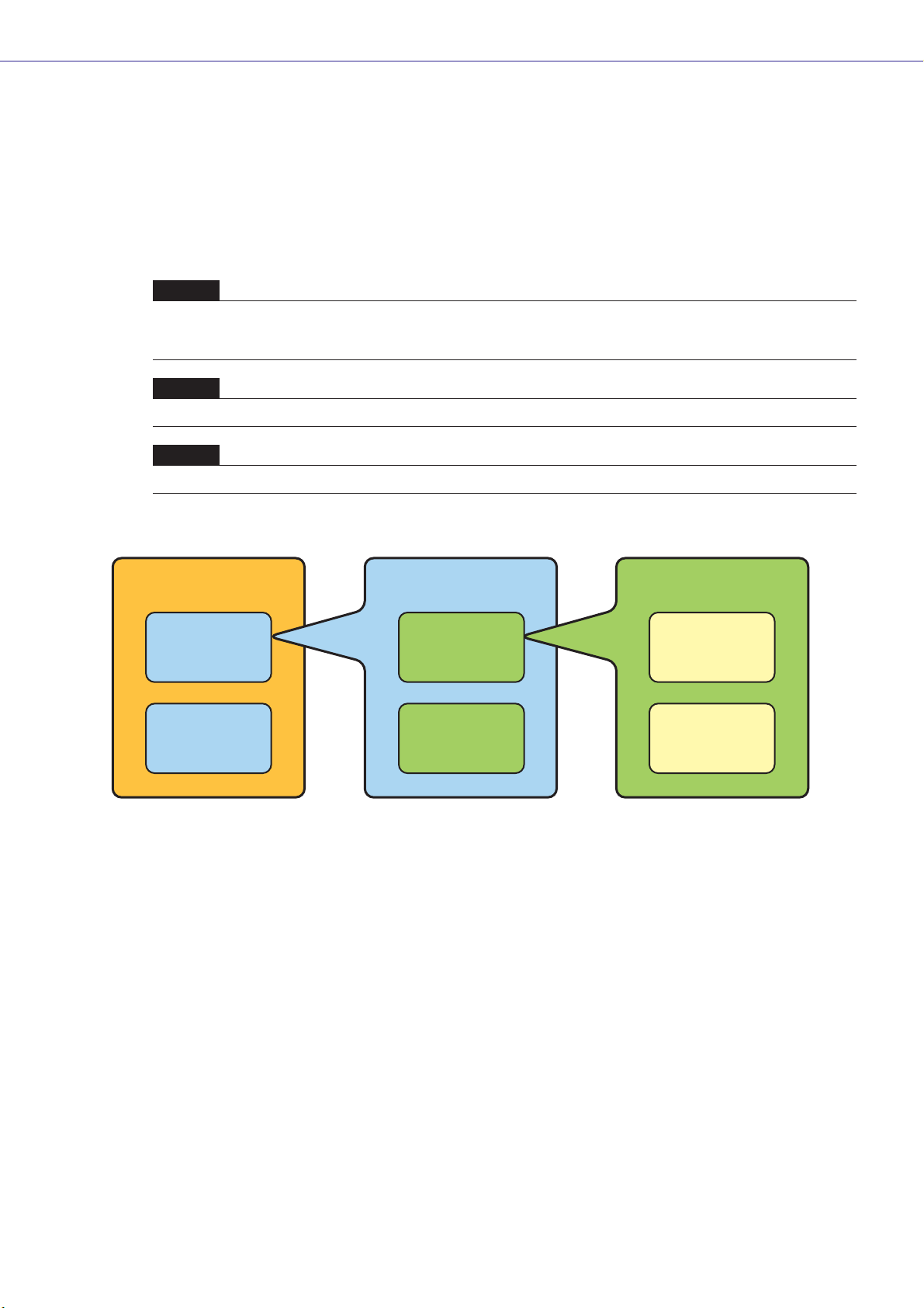
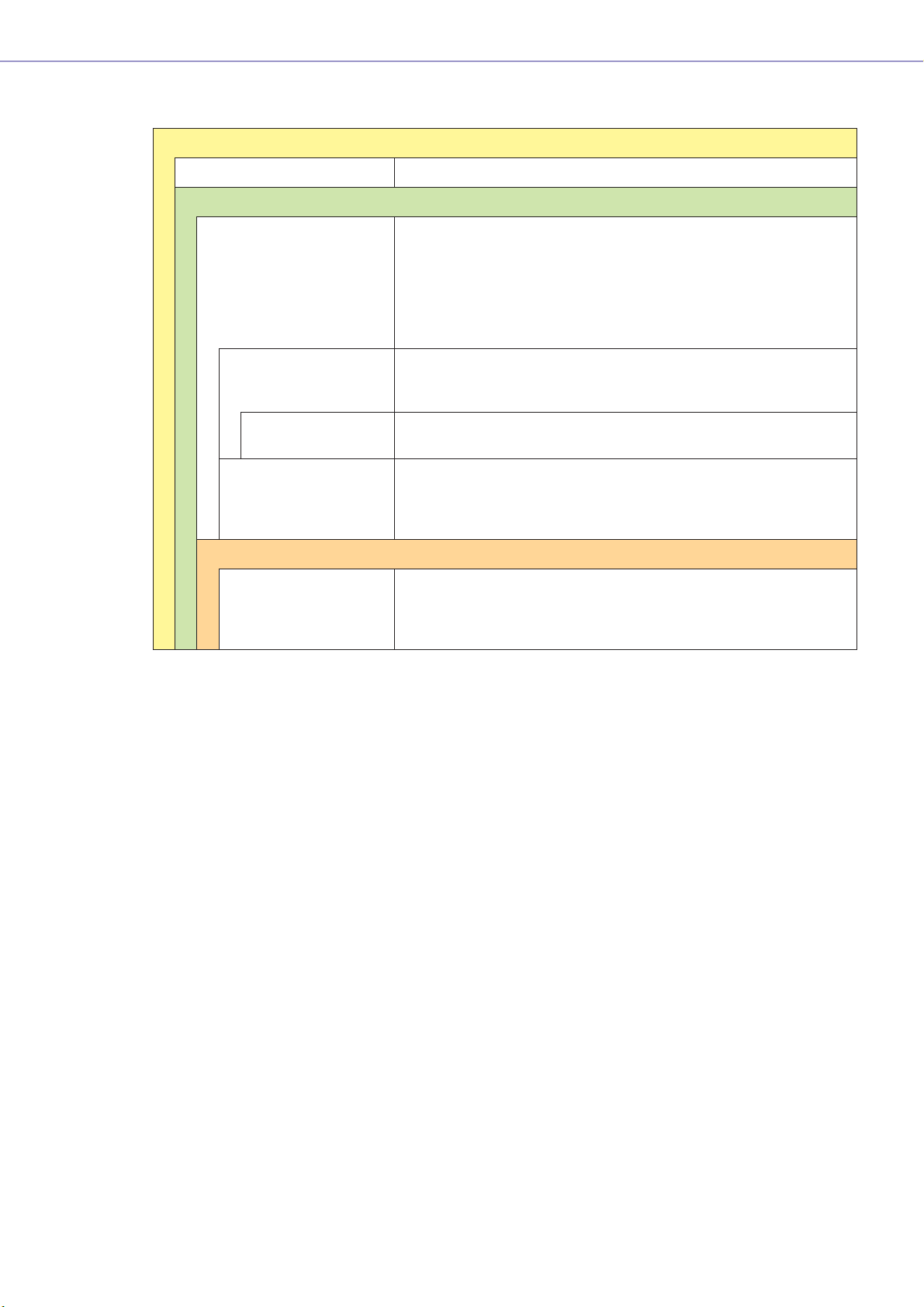
In an audio system including one or more DME units and/or SP2060 units, the “control space” is
logically organized using the concepts of “Area”, “Zone”, and “Device Group”. The space covered by
the entire system is the “Area”, while independent sonic spaces within that Area are called “Zone” A
group of DME or SP2060 units assigned to the same function are considered a “Device Group”.
An Area is comprised of one or more Zones, and each Zone can include up to 32 Device Groups.
A single Device Group can include as many as 16 devices. Each Device Group has one “Group
Master”.
NOTE
Meter response may deteriorate as the number of meters displayed in a single device group in DME Designer increases. In
such cases meter response can be improved by dividing the device group.
See “Changing Device Groups” on page 279.
NOTE
DME and SP2060 units cannot be combined in the same Device Group.
NOTE
All devices in a Device Group must be on the same subnet.
Getting Started
Area
Zone1
Zone2
Zone1
Device Group1
Device Group2
Device Group1
Device1
(Group Master)
Device2
(Slave)
DME Designer Owner’s Manual
3
Page 4
Getting Started
The DME Designer Software Application
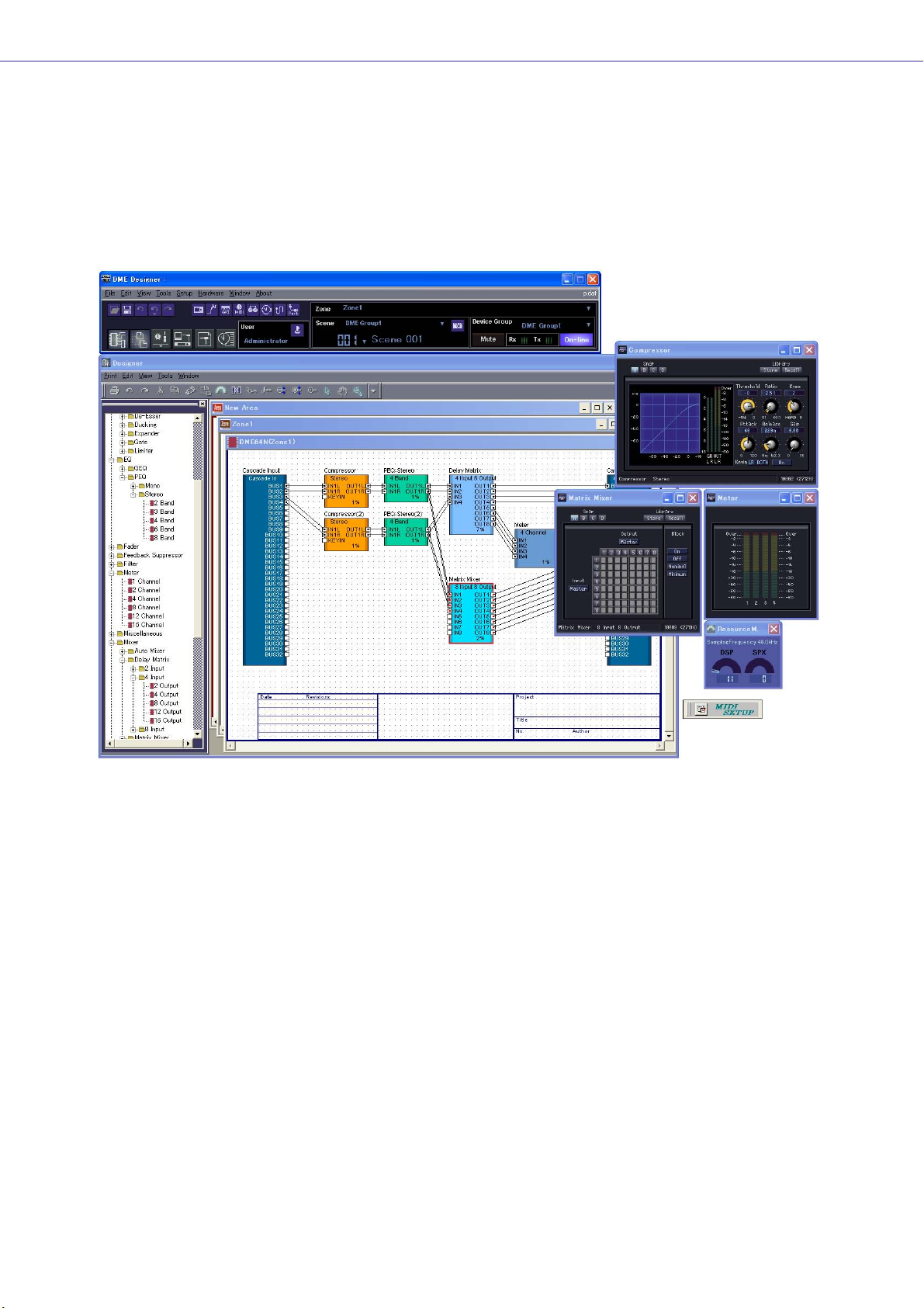
The DME Designer software application provides a convenient, central interface for the creation and
control of DME-based audio systems.
By connecting the computer on which the DME Designer application is running to a Group Master it
becomes possible to control multiple devices simultaneously.
With DME Designer, DME audio systems can be designed and configured via a comprehensive blockdiagram interface on the computer screen.
The main concepts used in the creation of DME audio systems are “Components”, “Configurations”,
“Preset Parameters”, and “Scenes”.
■ Components
Any independent signal-processing block, such as an equalizer, compressor,
input/output module, or external device control object is a “Component”.
■ Configurations
A “Configuration” is group of components, including their placement and interconnections.
DME Designer Owner’s Manual
4
Page 5
Getting Started
■ Preset Parameters
The set of parameters for all components in a Configuration is know as the Configuration's “Preset
Parameters”.
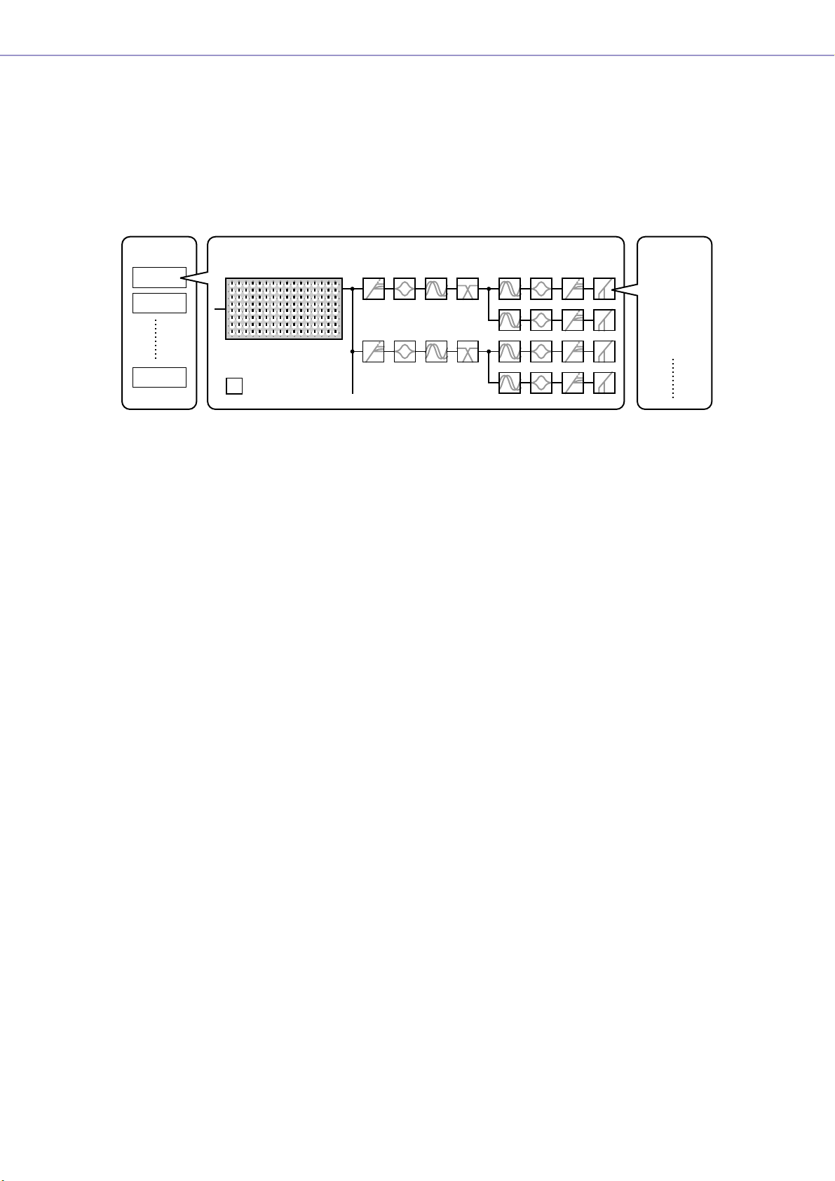
■ Scenes
A Configuration and its Preset Parameters are a “Scene”.
Composition of scene
Scenes
Scenes1
Scenes2
Scenes999
MATRIX MIXER PARAMETRIC EQ
16 x 8
= Components
Configurations
COMP/LIMITER
COMP/LIMITER
8 BAND
PARAMETRIC EQ
DELAY DELAYCROSSOVER
DELAY CROSSOVER
2WAY
DELAY COMP/LIMITER GATE
2WAY
DELAY COMP/LIMITER GATE
DELAY COMP/LIMITER GATE
PARAMETRIC EQ
PARAMETRIC EQ
PARAMETRIC EQ
PARAMETRIC EQ
COMP/LIMITER GATE
Preset
Parameters
Æ GATE
• Attack
• Decay
• Range
• Threshold
• Key in
• Hold
DME settings as well as Configuration and Preset Parameter settings are sent from the DME Designer
application running on the computer to the Device Master via USB or Ethernet, allowing each device
to function as a separate processor, independently from the computer. It is also possible to keep the
DME Designer application on line and control the devices in real time.
It is possible to use the DME Designer to create Configurations that include multiple devices when the
appropriate devices are connected.
Although it is possible to have multiple Zones in an Area, multiple Device Groups in a Zone, and
multiple Scenes and Configurations in a Device Group, only one Area, Zone, Device Group and
Configuration can be active and editable via the DME Designer at any one time. The active elements
are known as the Current Zone, Current Device Group, Current Scene, and Current Configuration.
DME Designer Owner’s Manual
5
Page 6
Getting Started
Data Handled by a DME Audio System
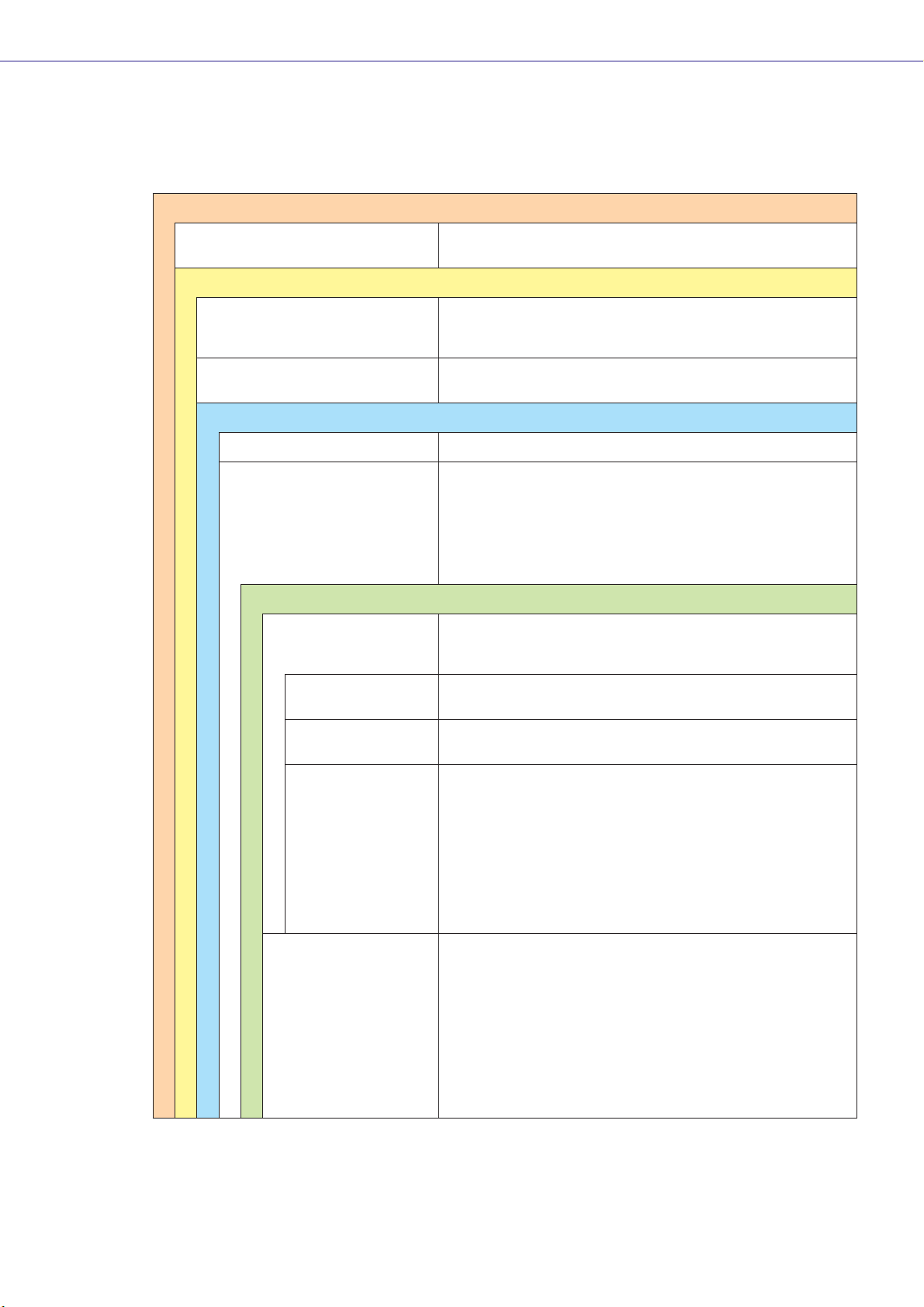
■ DME Data Structure
Common Overall Data
Scene Link Settings Settings required for linked scene operation between multiple
Data for Each Device Group
User Defined Button Settings Settings required for component parameter control from the
Global Parameter Link Settings Settings required for linked operation of the same types of
Data Used by the Scene Manager
MIDI program Change Settings Settings required to allow scene selection via MIDI commands.
Scenes The information required to switch audio data processing
Data for Each Device
Configurations A combination of the audio signal processing, audio input/
groups.
DME64N/DME24N or ICP1 panel.
Up to 24 parameters can be registered for control.
parameters between multiple devices.
setups.
Scenes include configurations and preset data.
The Scene Manager facilitates registration and management of
scene data.
Up to 999 scenes can be registered, and registered scenes are
managed by their scene numbers.
output, and external device control components and their
interconnections, created to create the desired audio system.
Local Parameter Link
Settings
Component Link
Settings
External Device
Settings
Preset Parameters The settings for the components in a configuration.
Settings that allow linked operation between similar types of
internal DME parameters.
Settings that allow linked operation between similar types of
internal DME components.
Settings required to allow control of component parameters from
external devices.
Independent settings are required for each device.
The external devices that can be used are as follows:
• MIDI Controller (MIDI Control Change, Parameter Change).
• GPI Controller.
• DAW Controller.
• AMX, Crestron, and other remote controllers.
• PM5D or other compatible mixing console (controlling DME
internal head amp)
Audio processing setups can be switched by changing the
preset parameters.
Components included in the preset parameter set are as
follows:
• GEQ, MatrixMixer, and other audio signal processing
components.
• Internal AD/DA (DME24N), Cascade (DME64N), and MY card
I/O components*.
• Components for external devices such as the AD8HR and
AD824 remote head amplifiers.
DME Designer Owner’s Manual
6
* Some settings not included.
Page 7
■ SP2060 Data Structure
Common Overall Data
Scene Link Settings Settings required for linked scene operation between multiple devices.
Data for Each Device
Scenes The information required to switch audio data processing setups.
Scenes include configurations and preset data, The last Library name recalled is
specified.
The Scene Manager facilitates registration and management of scene data.
Up to 99 scenes can be registered for 12 preset areas and 87 user areas, and registered scenes are managed by their scene numbers.
Configurations A combination of the audio signal processing, audio input/output, and external
device control components and their interconnections, created to create the
desired audio system.
Getting Started
Local Parameter Link
Settings
Preset Parameters The settings for the components in a configuration.
Data for Each Component
Library Settings specific to the speakers to be used.
Settings that allow linked operation between similar types of internal SP2060
parameters.
Audio processing setups can be switched by changing the preset parameters.
Preset parameters can be recalled by SP2060 units, but not edited.
In addition to the preset data provided, settings can be created by the DME
Designer.
DME Designer Owner’s Manual
7
Page 8
Getting Started
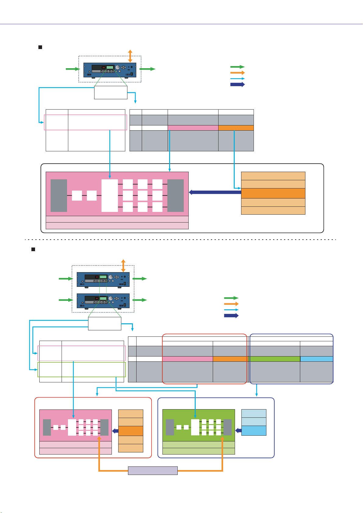
One DME unit/Device Group
Microphone
Mixer
External Head Amp
etc...
Input
Device Group
External Device (MIDI, GPI, DAW, AMX/Crestron, controlling DME internal head amp)
User Defined Button Scene Manager
LCD Display
Dome Low
Dome Mid
Dome Hi
....
Specifies the parameter to be changed.
Assigned Parameter
Crossover: Output Low: Level
Crossover: Output Mid: Level
Crossover: Output Hight: Level
(No Assign)
(No Assign)
(No Assign)
No.
001
002
003
004
005
006
....
Configuration
Output Processor for Dome
Delay EQ Dyn
MY8-AE
(Input)
Local parameter link settings
External device settings
EQ
Delay
Cross-
Over
Output
Scene Name
All On
Opening
Band Set 1
Band Set 2
Band Set 3
...
Power Amp
Processor
etc...
Confuguration
Output Processor for Dome
Output Processor for Dome
Output Processor for Dome
Output Processor for Dome
Output Processor for Dome
...
Specifies the configuration
and preset parameters combination.
MY8-AE
(Output)
Preset Parameters
All On
BGM & MC
Band 1
Band 2
Band 3
Set the value
Notes
Audio signal
Control signal
Data explanation
Setting preset parameters
Preset parameters for output processor
All On Component value
BGM & MC
Band 1
Band 2
Band 3
Two DME units/Device Group (When one DME unit doesn’t provide sufficient processing power, up to 16 DME units can be used)
External Device (MIDI, GPI, DAW, AMX/Crestron, controlling DME internal head amp)
Device Group
DME#1
Input Output
Microphone
Mixer
External Head Amp
etc...
For DME#1
For DME#2
Input Output
User Defined Button
LCD Display
Dome Low
Dome Mid
Dome Hi
Hall Low
Hall Mid
Hall Hi
....
Selects the parameter to be
edited from two DME units.
DME#1
Configuration
Output Processor
for Dome
Local parameter link settings
External device settings
Assigned Parameter
#1: Crossover: Output Low: Level
#1: Crossover: Output Mid: Level
#1: Crossover: Output Hight: Level
#2: Crossover: Output Low: Level
#2: Crossover: Output Mid: Level
#2: Crossover: Output Hight: Level
DME#2
Scene Manager
No.
001
002
003
004
005
006
....
Preset parameters Preset parameters
All On
BGM & MC
Band 1
Band 2
Band 3
Power Amp
Processor
etc...
Scene Name
All On
Opening
Band Set 1
Band Set 2
Band Set 3
...
Configuration
Output Processor for Dome
Output Processor for Dome
Output Processor for Dome
Output Processor for Dome
Output Processor for Dome
...
DME#2
Configuration
Output Processor
for Hall
Local parameter link settings
External device settings
For DME#1 For DME#2
Notes
Preset parameters
All On
BGM & MC
Band 1
Band 2
Band 3
Audio signal
Control signal
Data explanation
Setting preset parameters
Configuration
Output Processor for Hall
Output Processor for Hall
Output Processor for Hall
Output Processor for Hall
Output Processor for Hall
...
Specifies the configuration and preset
data combination in each DME
All On
BGM & MC
Band
Preset parameters
All On
BGM & MC
Band
Band
Band
DME Designer Owner’s Manual
8
Specifies the parameter to be linked between DME units.
Grobal Parameter Link
Page 9
NOTE
Separate SP2060 units normally handle scenes independently, but the Scene Link function can be set from the DME
Designer to allow linked scene operation.See “Scene Link Manager” on page 145.
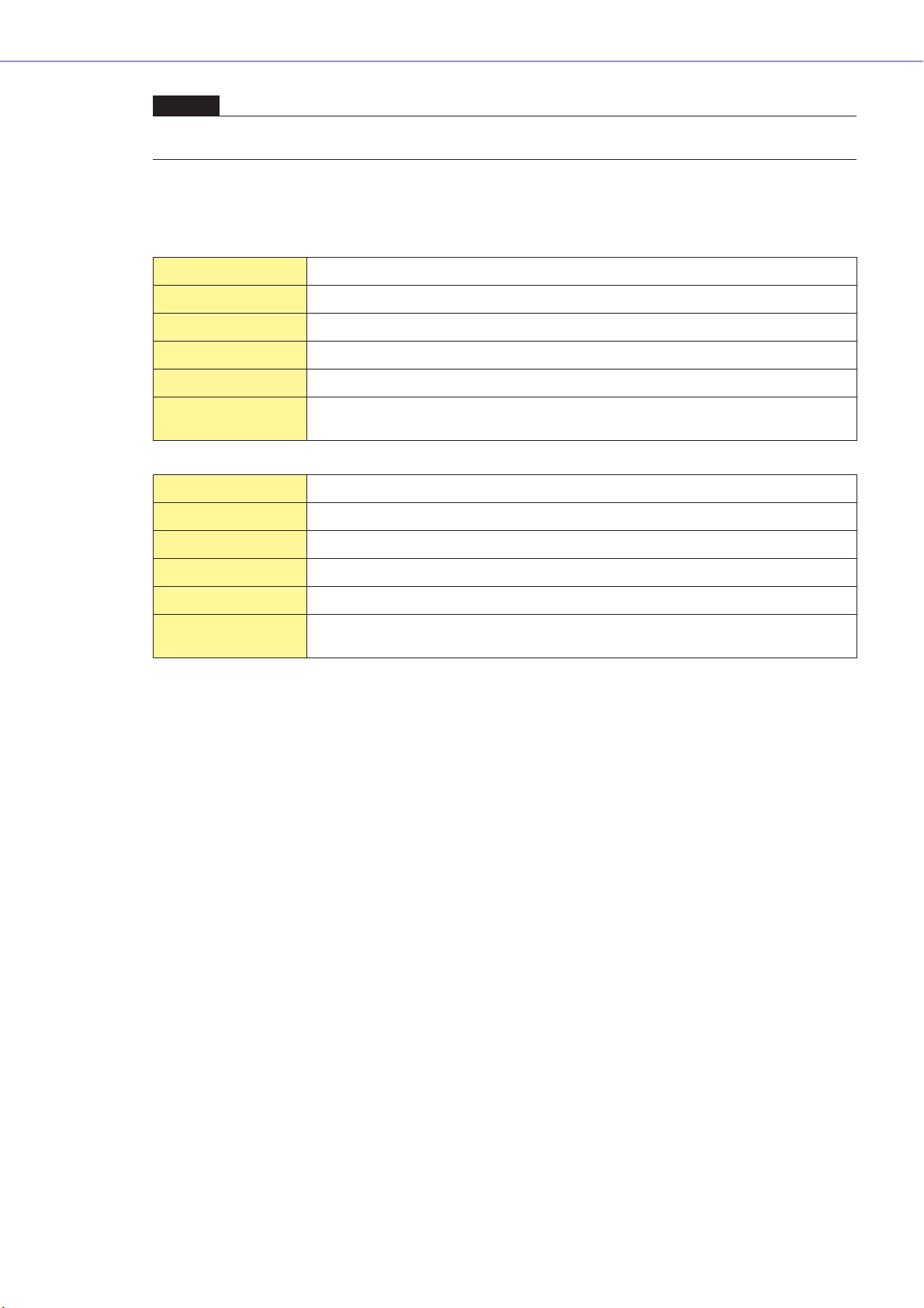
System Requirement
Operating System Windows® XP Professional/XP Home Edition/2000 Professional
CPU 1 GHz or better Intel® Core™/Pentium®/Celeron® family processor
Memory 256 MB or more
Hard Disk Capacity 300 MB or more
Display 1,280 x 1,024 pixels or better/High Color 16 bit or better
Getting Started
Other Mouse, CD-ROM drive, 100Base-TX/10Base-T Ethernet or USB connection
Operating System Windows® Vista Ultimate/Business/Enterprise
CPU 1.4 GHz or better Intel® Core™/Pentium®/Celeron® family processor
Memory 1 GB or more
Hard Disk Capacity 300 MB or more
Display 1,280 x 1,024 pixels or better/High Color 16 bit or better
Other Mouse, CD-ROM drive, 100Base-TX/10Base-T Ethernet or USB connection
environment.
environment.
DME Designer Owner’s Manual
9
Page 10

Getting Started
Main Changes from V1.0 to V1.1
■ Main Panel Window
• Instead of the former Parameter Link function, there are now two functions: a Global Link function
that links parameters within all DMEs in a zone and a Local Link function that links parameters
within a single DME unit. (page 89)
• The Synchronization function can now not only send data from DME Designer to the DME unit,
but can also synchronize by reading data from the DME unit. (page 91)
• Scene Increment/Decrement and Time Adjustment can now be assigned in the GPI input
function. (page 108)
• DME unit events can now be recorded by the Event Logger function and displayed in the Event
Logger window. (page 168)
• The time for executing an event can now be set by using the Event Scheduler function.
(page 133)
• Parameters in the current configuration can now be listed on the display and printed out by using
the Parameter List function. (page 138)
• The Wav File Manager can manage Wave files played by the Wav File Player. (page 145)
• Settings can be made by the DAW Control function that are used for controlling DMEs from a
DAW controller. (page 151)
• DME unit data can now be saved as a backup file by using the Backup function. (page 151)
■ Designer Window
• The port name display can now be switched between long name display and short name display.
(page 194)
• DME64N cascade connections can now be set. (page 209)
• Priority items can now be set when compiling configurations by using the [Compile Priority]
function in the “Preferences” dialog box. (page 208)
• Delay time can now be displayed for each component by using the Show Signal Delay function.
(page 291)
• Monitoring points can now be edited by using the “Monitoring Point List” dialog box. (page 292)
• The status of connections in a configuration can now be analyzed in advance by using the
Analyze function, without connecting the DME unit. (page 294)
•You can now set the action that occurs when you double-click a user module object. You can also
turn user module security ON or OFF, and set a password. (page 295)
• Libraries with component parameters saved in them can now be recalled from the context menu
for a component object. (page 352)
•A new rule for wiring prohibits connections to terminals that would short the terminator.
■ Component Editor/Component
•A status bar has been added to the component editor. It displays the component name,
component ID, and parameter IDs for parameters that are being edited. (page 306)
•A Snap function has been added that records parameters in the editor temporarily. Parameter
sets can then be switched by using the Snap buttons. (page 348)
• The meter's peak hold function can now be turned ON or OFF. (page 345)
•A Wav File Player component has been added for playing Wave files. (page 413)
• An effect component called SPX has been added that supports many different effect
applications, such as reverb, delay, and modulation effects, along with complex combinations of
multiple effects. (page 454)
•A Slot Out component editor has been added. (page 466)
• An Undo/Redo function is now available when using the design mode. It can undo the most
recent operation (control movement/resize/deletion).
DME Designer Owner’s Manual
10
Page 11

Changes from V1.1 to V1.2
■ Main Panel Window
• The synchronization algorithm has been refined for faster synchronization.
• Synchronization now can be executed from DME to DME Designer without any break in the
sound.
• In the following cases, synchronization can be executed from DME Designer to DME without any
break in the sound:
The second or later synchronization after starting DME Designer* and when differences in data
between the DME and DME Designer are limited to parameters within components, AD824/
AD8HR/DME24N AD/DA setting data, or MY card setting parameters.
* If the file was saved when DME Designer was closed, there will be no break in sound even in the first
synchronization after saving.
• Compile speed has been increased.
Up to three times faster when AutoDelayCompensation is turned On.
Up to two times faster when AutoDelayCompensation is turned Off.
• Synchronization is possible when no MY card or a different MY card is installed in the DME unit
(a confirmation dialog will appear).
• An option to automatically close the dialog after synchronization has been added. (page 50)
•A progress bar has been added to the Synchronization dialog. (page 49)
•A message appears to warn when synchronization will cause muting.
• The following operations can be performed while on line:
- Scene storage.
- Scene name changes.
- Fade ON/OFF and Fade Mode changes.
- Fade time changes.
- Parameter link setting changes.
• When a scene store is executed, that scene becomes the current scene.
•Wave files can be saved as DME data files, and are included in import/export operations.
(page 41)
•Wave files can be saved in the Wav file library.
• Event Log events can be output via GPI. (page 76)
• The on-line indicator appears as a button which can be used to switch between on-line and
off-line. (page 57)
• Scene edits cause the EDIT indicator to appear. (page 55)
• An auto file save function (Auto Save, post synchronization) has been added. (page 70)
• Different zones can be specified for use by different users. (page 152)
• Scene parameters related to User Defined Button, Program Change, GPI In and GPI Out can be
set via the Scene Manager. (page 79)
• [Select All] and [Clear All] buttons have been added to the Scene Manager Recall Safe dialog.
(page 83)
• User Control can be created for individual users as well as security levels. (page 86)
•A Remote Control Setup List has been added. (page 133)
This list can be used to make detailed settings for a new software protocol that allow the DME to
be controlled from AMX, Crestron, and similar devices.
Refer to the “DME-N Remote Control Protocol Specifications” document for details about the
communication protocol. Information about the “DME-N Remote Control Protocol Specifications”
document can be found at the Yamaha pro Audio website (URL below).
http://www
• It is possible to specify whether listed events will be executed by the Event Scheduler.
(page 133)
.yamahaproaudio.com/
Getting Started
DME Designer Owner’s Manual
11
Page 12

Getting Started
• The order of same-time events can be changed in the Event Scheduler. (page 133)
• Exceptions can be specified for Event Scheduler execution day/time. (page 101)
• Event Scheduler execution times can be specified in 1-second increments. (page 100)
• Head amp gain and MY-Card can be set via GPI, MIDI, User defined Button, DAW Control.
• Parameter values, scene recall, GPI output, Wave file playback, and head amp gain can be set
via the User Defined Buttons. (page 126)
• The Component Lock function dialog is separate from the Parameter List dialog. (page 144)
• Shortcuts can be freely set as required. (page 150)
• Files can be saved in the DME unit. (page 68)
•A [Close All Editor Windows] button has been added to the Window menu. (page 67)
• External head amp parameters will be recognized by the DME unit when either the DME or the
external head amp (AD824, AD8HR) are turned on. Execute a scene recall to send DME settings
an external head amp.
• This manual is now separate from the DME Designer installer, and can not be accessed from the
DME Designer menus.
■ Designer Window
• The following operations can be carried out via the shortcut keys.
- Navigator
- Activate Navigator
- Activate Toolkit
- Activate Design Window
- Select Left Port and Start Wiring
- Select Right Port and Start Wiring
- Wire Auto Single to Right
- Wire Auto Multi to Right
- Wire Auto Single to Left
- Wire Auto Multi to Left
- Delete Wire
• It is now possible to simultaneously edit multiple objects of the same type.
Example: Change the thickness or color of multiple wires at once.
• Files related to user modules (user module files, library files, user module editor files) can be
combined and exported/imported as a single file.
• Port colors can be independently specified for each port type. (page 198)
• Default wire thicknesses and types can be independently specified for each port type.
• An automatic hot-spot connection function has been added. (page 271)
• Port display has been added to External Device, Picture, DME, and ICP1 objects.
• When drawing wires the keyboard cursor keys can be used to move the mouse cursor, and the
<Enter> key can be used to create nodes.
• When drawing wires <Shift> key plus <→> key and <Shift> key plus <←> key combinations can
be used to automatically connect horizontally-aligned hot spots.
• DME object ports can be freely specified.
• Compilation of configurations with loop connections is possible when Auto Delay Compensation
is On.
• The name has been changed from “Foot Monitor” external device to “Floor Monitor.”
• Addition External Device types have been provided.
• External Devices can be double-clicked to open a file saved by other applications. (page 220)
• Picture objects can be double-clicked to open a specified editor. (page 236)
•Text objects can be double-clicked to open a specified editor. (page 239)
DME Designer Owner’s Manual
12
Page 13
Getting Started
• User module port labels can be edited. (page 233)
• Graphics can be placed to represent user modules. (page 232)
• The Legend field automatically resizes to accommodate project names and titles of different
lengths.
•A Generic “MY-Others” setting has been provided to accommodate third-party MY cards.
■ Component Editor Window
• Undo and Redo are now shortcut compatible.
•A scroll bar appears when the size of the component editor window is reduced.
• The size and position of the component editor window are memorized.
• An option to allow mouse-over zooming of the edit box has been added. (page 309)
•A [Back] button that allows switching between related parent and child windows has been
added. (page 306)
•A [Close All Editor Windows] button has been added to the contextual menu.
• Source Selector, Speaker Processor, Limiter, Slot In, Cascade In, and Cascade Out components
have been added.
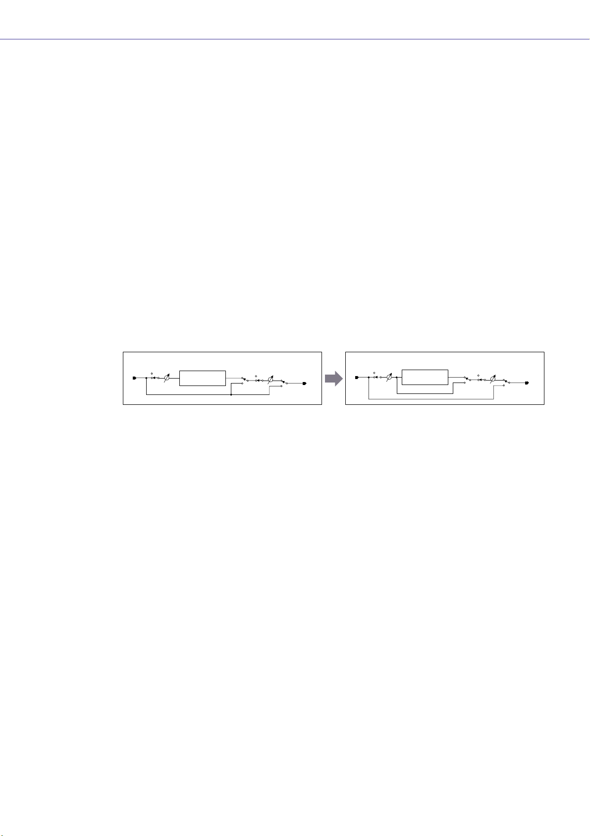
• The Delay algorithm has been revised. (page 385)
- LEVEL and MUTE are effective when Delay is Off for each channel.
- The name of the overall Delay [On] parameter has been changed to [All Bypass].
Input
Input
Input
Mute
IN
Level
Delay
Mute Level
On
Delay On
OUT
IN
Mute
Input
Level
Delay
On Mute Level
Delay All Bypass
OUT
• The bus send level range for Delay, Matrix, and Matrix Mixer components has been changed to
-∞ through 0.0 dB.
• Snap copy is possible. (page 349)
• Snap can be retained until the application is quit or another file is opened.
• Security status is displayed in the user module editor status bar.
• Multiple controllers can be selected by clicking while holding the <Ctrl> key when the editor is in
the design mode. (page 344)
• [Picture], [Text], [Box], [Ellipse], and [Frame] have been added to the tool palette of the user
module editor and user control editor design mode. (page 311)
• Controller properties can be accessed by double-clicking controllers in the user module editor or
user control editor design mode. (page 330)
• Picture and Text objects can be clicked to open a specified editor in the user module editor or
user control editor.
• The User Module Editor and User Control Editor offer a greater range of customization options for
color, size. etc., of the placed controls.
■ MIDI Setup
•A MIDI Setup minimize function has been added.
■ V1.2 Precautions
• When using project files (*.daf) created by version 1.1.5 or earlier, synchronize from the DME
Designer to the DME unit for the first synchronization.
•Project files (*.daf) created using version 1.2 will not open properly on version 1.1.
DME Designer Owner’s Manual
13
Page 14

Getting Started
Changes from V1.2 to V2.0
■ General
• Support added for DME8i-C/DME8o-C/DME4io-C, SP2060 units and MY16-CII.
• “Device Groups”, or groups of the same type of device, have been added at the lowest Zone
level.
• It is now possible to have one master device per device group rather than one master device per
zone. This means that it is possible to have multiple master devices in a single zone.
•Group masters can now be assigned regardless of the IP address. This makes it possible to have
multiple device groups at a single network address.
• Configurations can be created and deleted for each device group.
■ Component
•A Feedback Suppressor component has been added. (page 402)
• The Speaker Processor component PEQ “Q” parameter now goes to “63”. (page 447)
■ Main Panel Window
• Firmware and component data can now be updated simultaneously. (page 175)
•A Recovery Update function that allows recovery from program corruption has been added.
(page 177)
•A Component Link function that allows simultaneous linking of all component parameters has
been added. (page 89)
• Scene Link function that allows simultaneous control of multiple devices in different device
groups has been added. (page 145)
•A Protect function has been added to the scene manager. (page 79)
• Card settings are no longer included in scene data.
•A Utility window has been added to allow editing of device utility settings. (page 161)
• The Local Parameter Link display order has been changed. (page 89)
• Parameter Link operation can now be turned on or off for each device group. (page 89)
• Compilation and analysis is now possible even if no connections have been made.
• Navigator window hide/show can now be selected from the main window.
• The Event Logger can now display only the event data for a specified device. (page 72)
• The GPI terminal names have been changed from [CH] to [PORT].
DME Designer Owner’s Manual
14
■ Designer Window
•A hand tool for window movement has been added. The hand tool can be selected via the hand/
arrow icon in the toolbar, or from the [Tools] menu. The hand tool can also be temporarily
selected by holding the spacebar on your keyboard.
• Window magnification and reduction can now be controlled via the mouse wheel while holding
the keyboard “Ctrl” key.
• Horizontal scrolling can be controlled via the mouse wheel while holding the keyboard “Shift” key.
• The Edit Mode on/off can now be changed from the tool bar. (page 180)
• Scene information now appears in DME objects, and the Scene Manager can be launched from
the scene information display. (page 79)
• An [On-line] button has been added to DME objects, and synchronization is now possible.
(page 57)
• Sampling frequency display has been added to the resource meter window. (page 184)
Page 15

Getting Started
• Sampling frequency display has been added to the configuration window status bar. (page 287)
• The sampling frequency is now displayed during analysis.
• Double-clicking the component name now opens the properties window.
• Organization of the Tool Kit window has been changed. (page 186)
•A [Draw Image] checkbox that displays or hides the worksheet background image file has been
added to the Sheet properties. (page 201)
• [Configuration Manager] has been added to the contextual menu that appears when a DME or
SP2060 object is right-clicked. (page 205,page 213)
• [Recall Component Library] and [Store Component Library] now appear in the contextual menu
that appears when a component is right-clicked, even when the Edit Mode is OFF.
• The Compile Settings can now be edited for each DME unit. (page 208)
• Only one Zone window is now provided for multiple configurations.
• The [Export DXF] and [Preferences] commands have been moved from the [Print] menu to the
[Tools] menu.
• [Configuration] has been changed to [Configuration Manager] in the [Tools] menu.
• When [Prohibit Diagonal Connections] in the [Tools] menu is active it is possible to select 2
diagonal points and those points will automatically be connected by a combination of horizontal
and vertical wires.
■ Component Editor Window
•A [Level Meter Enable] command that displays or hides the meter values has been added to the
contextual menu. Hiding the meters can result in increased communication speed in some
cases. (page 346)
•A [Display Order] function that allows the order of the controllers to be changed as required has
been added to the User Control Editor and User Module Editor. (page 311)
• An [Add Component to Component Link] command has been added to the controller contextual
menu.(page 356)
• The registered group is now displayed in the [Add Parameter to Parameter Link] submenu of the
contextual menu of controllers registered for Parameter Link operation.(page 354)
• Increased speed when selecting and dragging a large number of controllers in the User Control
Editor and User Module Editor
• It is now possible to switch from the Navigator window to Zone display while online.
■ V2.0 Precautions
Please use DME Designer V2.0 with DME64N/24N V2.0 or higher, DME8i-C/DME8o-C/DME4io-C
V2.0 or higher, and SP2060 V1.1 or higher.
See the Yamaha Pro Audio website for compatibility details (http://www.yamahaproaudio.com/).
When DME64N/24N and DME8i-C/DME8o-C/DME4io-C are used together in the same device
group, faster communication speed as well as smoother DME Designer meter display can be
obtained by assigning a DME8i-C/DME8o-C/DME4io-C unit as the device group master.
DME Designer Owner’s Manual
15
Page 16

Getting Started
Changes from V2.0 to V3.0
■ General
• DME8i-ES/DME8o-ES/DME4io-ES support.
• The DME Designer and DME-N Network Driver installers have been combined, so the
appropriate DME-N Network Driver version is now installed automatically with the DME Designer
application.
• The following connections to the Slave DME units are now possible when a DME Satellite unit is
assigned as the Device Group Master:
- USB/Ethernet connection to the computer (DME Designer).
- Cascade connection to control from the PM5D console (DME64N only).
■ Component
• Ambient Noise Compensator component added (page 365).
• Audio Detector component added (page 367).
• Auto Gain Control component added (page 368).
• Auto Mixer II component added (page 414).
• Simple Mixer component added (page 433).
• Room Combiner component added (page 443).
• Matrix Mixer and Router component variations added.
■ Main Panel Window
•To allow project information to be easily reproduced on a different computer, it is now possible to
export and import all necessary files at once, rather than only project files with the “.daf”
extension (page 42).
•A Device Information window that lists the status of all devices has been added (page 178).
• It is now possible to individually set each user control to determine whether it will open
automatically when the project file is opened (page 86).
• In accordance with the above change, the Startup User Control item has been removed from the
Security dialog box.
• It is now possible to assign Direct Parameter Value to the GPI input function, and assign Direct
Parameter Value and Audio Detector to the GPI output function (page 106, page 116).
• An option that automatically saves the project file (.daf extension) in the DME unit when going
online has been added (page 92).
• It is now possible to control internal DME-24N/DME8i-C/DME4io-C/DME8i-ES/DME4io-ES head
amps from a PM5D or other compatible mixing console (page 135).
• Remote control from AMX, Crestron, and similar controllers is now possible via Ethernet
connection only for DME Satellite units. (page 165).
• The display format of the parameter values displayed in the Remote Control Setup List and
Parameter List dialog box can now be switched between the internal settings and the values
displayed in the editor windows (page 133, page 141).
• The Event Logger window can now display additional error messages shown on the DME display
panel (page 77).
• It is now possible to set the DME unit so that the internally stored event log is not erased
(page 74).
• Improvements have been made to the additional error message information shown in the Event
Logger window.
• The DME unit internal clock and DME Designer time display now support daylight saving time
(DST) (page 171).
• Firmware updates can now be applied to entire device groups, for improved speed and
efficiency.
DME Designer Owner’s Manual
16
Page 17

Getting Started
■ Designer Window
• It is now possible to set a “clear” background color for text, box, and ellipse objects (page 239,
page 241, page 243).
• Password entry is now required when opening a User Module Properties dialog box or saving/
exporting in a user module to which security has been applied.
• Linked software applications can now be launched from the Slot component contextual menu
(page 227).
• User module templates that use the same library are now categorized and displayed as user
module groups (page 296).
• Image files are now included in User Module exports.
• Component and parameter links can now be copied when DME objects, components, and user
modules are copied/pasted or duplicated.
• Parameter links are now saved when User Module data is saved/exported.
• When already-placed picture files are replaced, they will be updated and displayed correctly
without the need to restart the DME Designer application.
■ Component Editor Window
• [Line] and [Scene Recall] tools have been added to the User Module Editor and User Control
Editor design modes, allowing placement of lines and scene recall buttons (page 318).
• In the User Module Editor and User Control Editor it is now possible to convert placed sliders to
knobs, and vice-versa (page 329).
• More options are available for customizing the controls listed below in the User Module Editor
and User Control Editor:
- A property dialog box has been added for sliders, allowing customization of direction, scale,
color, size, and other parameters (page 331).
- Level meter size can be customized (page 333).
- A property dialog box has been added for slider level meters, allowing customization of
direction and size (page 334).
- Knob color and knob background color can be customized (page 330).
- Text background color can be customized (page 338).
- A property dialog box has been added for indicators, allowing customization of color and size
(page 334).
■ V3.0 Precautions
Use DME Designer V3.0 only with DME64N/24N V3.0 or higher, DME Satellite V3.0 or higher, and/or
SP2060 V1.2 or higher. Refer to the Yamaha Pro Audio website (http://www.yamahaproaudio.com/)
details on combinations.
When combining DME64N/24N and DME Satellite units in a device group, be sure to assign a DME
Satellite unit as the device group master. Synchronization cannot be performed if a DME64N/24N is
assigned as the device group master.
When using the Windows Vista operating system, use only USB-MIDI Driver V3.0 or higher, and
DME-N Network Driver V1.2 or higher.
DME Designer Owner’s Manual
17
Page 18

Contents
The DME Audio System Network .............................................. 3
The DME Designer Software Application .................................. 4
Data Handled by a DME Audio System..................................... 6
Chapter 1 Before Using 20
Installing DME Designer .......................................................... 20
Starting DME Designer............................................................ 20
Closing DME Designer ............................................................ 22
Chapter 2 DME Designer Overview 23
Names and Functions of the Windows .................................... 23
Users and Security .................................................................. 28
Files Used by the DME DESIGNER ........................................ 31
Configuration Creation Procedure ........................................... 46
Online ...................................................................................... 47
Chapter 3 Main Panel Window 52
Names and Functions of the Windows .................................... 52
Main Panel Window Menu....................................................... 58
DME File Storage .................................................................... 68
Preferences ............................................................................. 69
Event Logger ........................................................................... 72
Scene Manager ....................................................................... 79
User Control ............................................................................ 86
Parameter Link ........................................................................ 89
Synchronization (DME Designer and Unit Synchronization) ... 91
Event Scheduler ...................................................................... 95
Wav File Manager ................................................................. 102
GPI ........................................................................................ 106
MIDI....................................................................................... 119
User Defined Button (User Defined Parameters) .................. 126
DAW Control.......................................................................... 130
Remote Control Setup List .................................................... 133
Internal HA Control ................................................................ 135
Parameter List ....................................................................... 141
Component Lock ................................................................... 144
Scene Link Manager.............................................................. 145
SP2060 Library Manager....................................................... 147
MIDI Port Setup ..................................................................... 149
Shortcut Keys ........................................................................ 150
Security (Creating Users and Making User Settings) ............ 151
Network Setup ....................................................................... 159
Utility...................................................................................... 161
Word Clock ............................................................................ 168
Monitor Out............................................................................ 170
Clock...................................................................................... 171
Language Settings................................................................. 173
Backup................................................................................... 174
DME Firmware Update .......................................................... 175
Device Information................................................................. 178
Chapter 4 Designer 180
Editing Configurations ........................................................... 180
Designer Window .................................................................. 181
Toolkit Window ...................................................................... 186
Designer Window Menu ........................................................ 191
Objects .................................................................................. 198
Design Window Shared Settings and Operations ................. 255
Drawing and Editing Wires .................................................... 266
Adding, Deleting, and Renaming a Zone............................... 277
Changing Device Groups ...................................................... 279
Adding, Deleting, and Renaming a Configuration ................. 281
Area Window ......................................................................... 283
Zone Window......................................................................... 284
Configuration Window ........................................................... 287
User Module .......................................................................... 295
Chapter 5 Editor Window 305
Component Editor Window.................................................... 305
User Control Editor/User Module Editor ................................ 311
Operation Mode and Design Mode........................................ 344
Context Menu ........................................................................ 345
Snap ...................................................................................... 348
Library.................................................................................... 350
Creating Parameter Links...................................................... 354
Creating Component Links .................................................... 356
Chapter 6 Component Guide 357
Types of Components ........................................................... 357
Ambient Noise Compensator................................................. 365
Audio Detector....................................................................... 367
Auto Gain Control .................................................................. 368
Crossover .............................................................................. 369
Crossover Processor ............................................................. 373
Delay ..................................................................................... 385
Dynamics............................................................................... 387
Equalizer (EQ) ....................................................................... 397
Fader ..................................................................................... 401
Feedback Suppressor ........................................................... 402
Filters..................................................................................... 403
Meter ..................................................................................... 411
Miscellaneous........................................................................ 412
Mixer...................................................................................... 414
Pan ........................................................................................ 436
Room Combiner .................................................................... 443
Router.................................................................................... 444
Source Selector ..................................................................... 446
Speaker Processor ................................................................ 447
SPX ....................................................................................... 454
Slot ........................................................................................ 465
Cascade ................................................................................ 467
Analog Input and Output........................................................ 469
SP2060 Input and Output ...................................................... 470
CobraNet Input and Output ................................................... 471
EtherSound Input and Output................................................ 473
MY-Card ................................................................................ 474
Remote Controlled Head Amp............................................... 478
Component Glossary............................................................. 480
DME Designer Owner’s Manual
18
Page 19

Appendix 484
Options .................................................................................. 484
Main Display .......................................................................... 486
Parameter Edit Displays ........................................................ 487
Utility Displays ....................................................................... 491
Troubleshooting 496
Index 497
Getting Started
DME Designer Owner’s Manual
19
Page 20
Chapter 1 Before Using
Installing DME Designer
To use DME Designer, you must first install the software on the computer. Before you can connect the
DME Designer software to the DME or SP2060 unit, you must first install the USB MIDI Driver or the
DME-N Network Driver, according to how you will be connecting, and then make the appropriate
settings.
For instructions about the installation and setup for the DME Designer and DME-N Network Driver, and
about the installation for the USB-MIDI Driver, see the “DME Setup Manual.”
NOTE
Initial settings for DME Satellite units must be transferred via USB-MIDI, so it is necessary to properly install the USB-MIDI
Driver.
Starting DME Designer
The DME Designer software is started from the [Start] menu. DME Designer is used with one user
logged on. The user logs on when the software is started.
■ DME Designer Start Up and Logon (When Auto-Logon Is Not Set)
1 Click [Start] ➞ [All Programs] ➞ [YAMAHA OPT Tools] ➞ [DME Designer] ➞ [DME
Designer].
NOTE
In Windows2000, click [Start] → [Programs] → [YAMAHA OPT Tools] → [DME Designer] → [DME Designer].
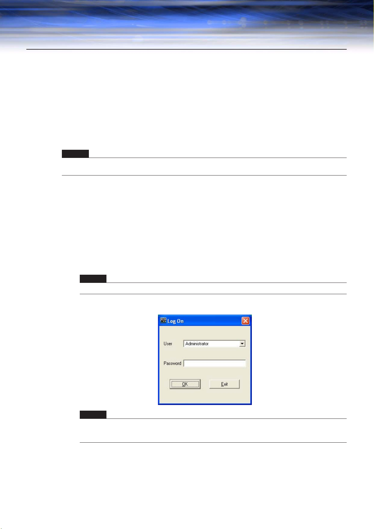
The “Log On” dialog box will be displayed.
NOTE
Automatic log-on is the default setting. If the automatic logon feature is enabled, the “Log On” dialog box will not be
displayed when the application is started. Instead, the auto-logon user will be logged on automatically. See page 30
for information about auto-logon.
DME Designer Owner’s Manual
20
Page 21
Chapter 1 Before Using
2 Click the [▼] at the right of the [User] box, and select the user.
If no user has been created, only [Administrator] will appear in the list. When starting DME
Designer for the first time after installing, select [Administrator].
3 Enter the password into the [Password] box.
Enter the password set for the user.
If no password has been set, leave the password box blank when you log on.
4 Click the [OK] button.
DME Designer starts up.
■ When Automatic Logon Has Been Set (page 30)
If automatic logon has been set, the “Log On” dialog box will not be displayed. The user set for
automatic logon will be logged on.
With automatic log on, even if a password is set for a user, it will not be requested during log on.
This is useful when logging on a specific user.
■ Starting by Opening a Project File
DME Designer starts when a project file with a saved configuration is opened. When the project file
is opened, DME Designer is started with the window configuration that was in place when the file
was last saved.
DME Designer Owner’s Manual
21
Page 22
Chapter 1 Before Using
Closing DME Designer
To close DME Designer, click [Exit] on the [File] menu of the Main Panel window. It can also be closed
by clicking the [Close] button on the Main Panel window.
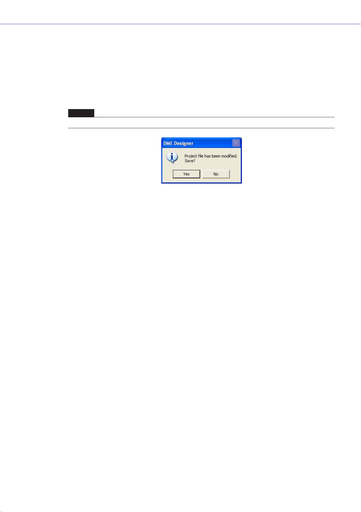
1 Click [Exit] on the Main Panel window [File] menu.
When you try to close DME Designer, “Project File has been modified. Save?” will be displayed in a
dialog box.
NOTE
Sometimes the “Project File has been modified. Save?” dialog box will not be displayed.
2 To save the file, click [Yes]. To close without saving, click [No].
If you click [Yes], the File Save dialog box will be displayed.
DME Designer Owner’s Manual
22
Page 23
Chapter 2 DME Designer Overview
Names and Functions of the Windows
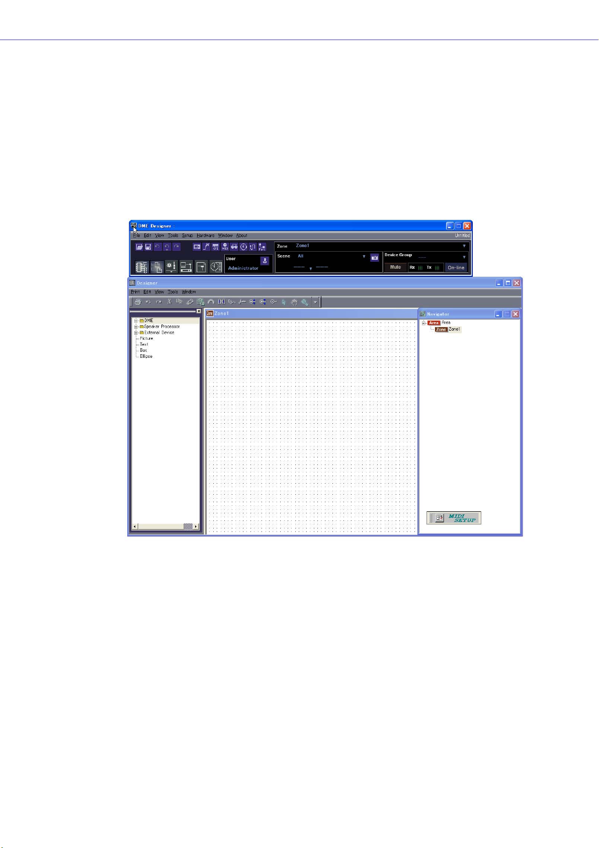
The DME Designer software has several windows, including the Main Panel window, Designer window,
Component Editor window, Resource Meter window, and others.
Main Panel Window
Designer Window
Component Editor Window
Resource Meter Window
Main Panel Window
Menus and buttons are available in the Main Panel window. The current DME Designer environment,
including the active zone, device group and scene the currently logged on user name, and the
connection status to the DME unit are displayed on the right side of the Main Panel window.
DME Designer Owner’s Manual
23
Page 24
Chapter 2 DME Designer Overview
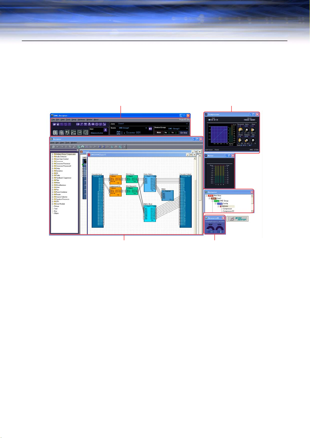
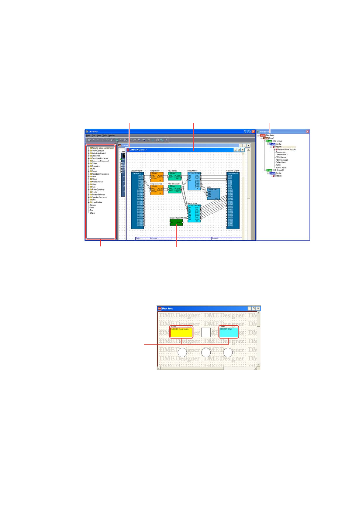
Designer Window
The Designer window displays several different windows. First among them is the Area window, where
you can manage the entire system. The Area window includes one or more Zone windows, which in
turn include one or more DME or SP2060 units that are used to build a zones within the area. Next is
the Configuration window, where you create the internal configuration of each DME or SP2060 unit.
Within the Configuration window are the User Module windows, where you can assemble often-used
components into templates the Toolkit window, which displays objects used in the other windows as
the basic building blocks for sound designs; and the Navigator window, which lets you grasp the
overall status of the system at a glance.
Toolkit Window
Configuration Window
User Module Window
Navigator WindowZone Window
■ Area Window
The Area window is used for designing areas, which manage the entire system. While at least one
zone is included within an area, multiple zones can be arranged there.
DME Designer Owner’s Manual
24
Zones
Page 25
Chapter 2 DME Designer Overview
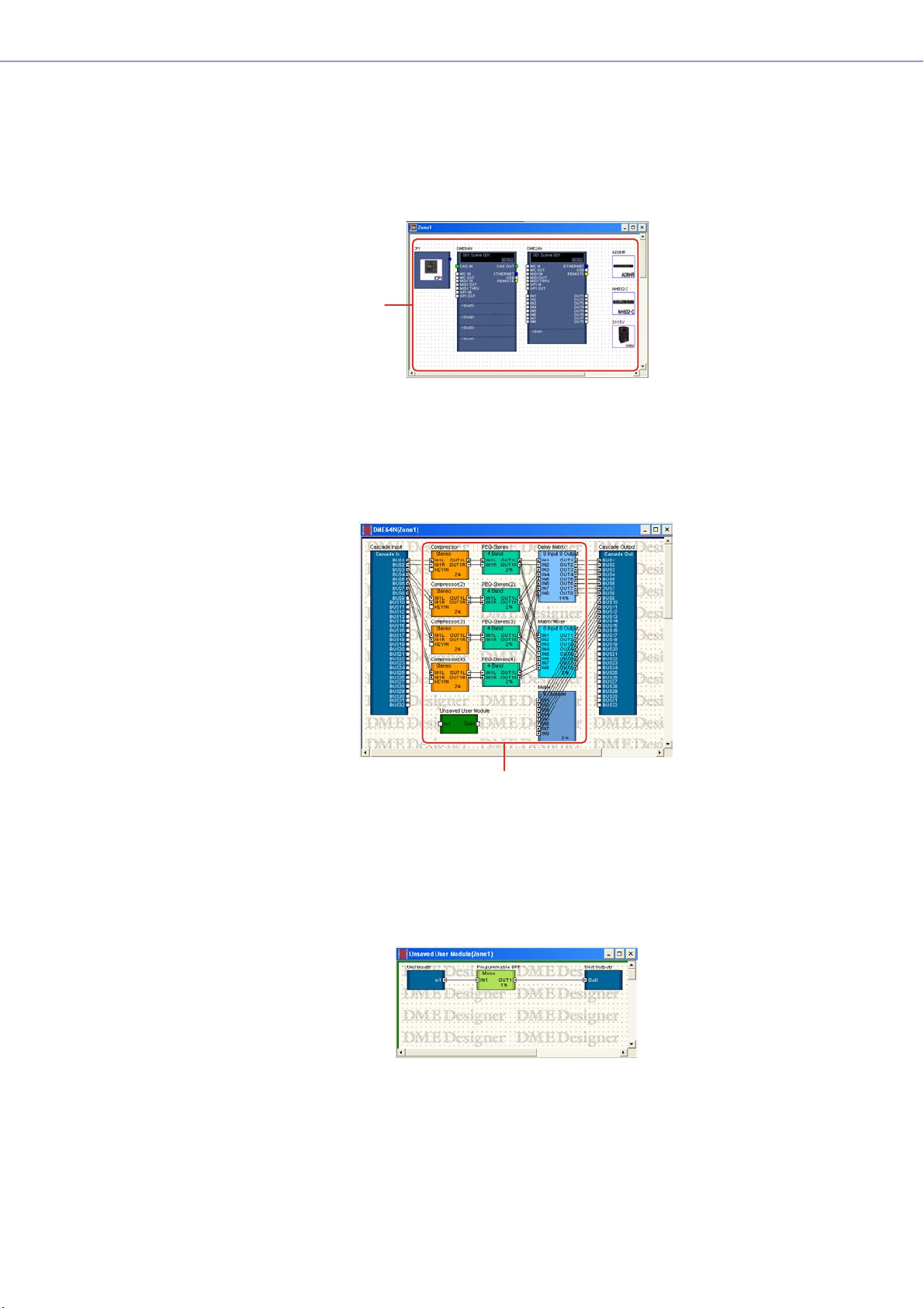
■ Zone Window
The Zone window is used to design zones within the area. A zone is a more concrete blueprint that
includes at least one DME or SP2060. It shows the DME’s connections with other devices and the
wiring between them. You can create multiple zones.
The DME and SP2060 units and connected devices are arranged in each Zone window, creating
configurations.
Configurations
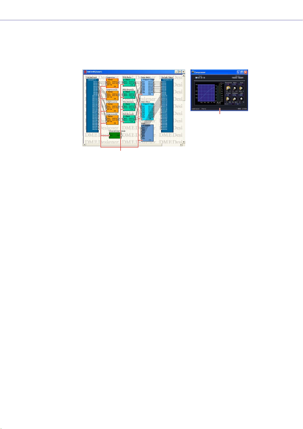
■ Configuration Window
The Configuration window is used to design the internal configuration of each DME unit contained
in the Zone window. By arranging and connecting components in the Configuration window, you
can create things like complex processors or matrix mixers, that determine the actual internal
structure that operates each DME unit.
Components
■ User Module Window
The User Module window is used for designing user modules that can be arranged in the
Configuration window. You can create original modules by combining multiple examples of oftenused components. When you save these modules as templates you can recall them easily
whenever you want.
DME Designer Owner’s Manual
25
Page 26

Chapter 2 DME Designer Overview
■ Toolkit Window
The Toolkit window displays the objects that you can use in each window that can be displayed in
the Designer window. Those windows are the Area, Zone, Configuration, and User Module
windows. The Toolkit displays different objects, according to the currently active window. To place
an object in a window, double-click it in the Toolkit window where it is displayed or drag it to the
currently active window.
■ Navigator Window
The Navigator window displays the area, zones, configurations, and components in a hierarchal
fashion that lets you check their status as a whole. When editing offline, you can click an area
name, zone name, or configuration name to make that window active. Clicking a component name
will open the component editor window for that component.
■ Resource Meter Window
This window provides an indication of component usage for each DME unit currently placed in the
Configuration window. The usage percentage increases as the number of components increases. The
component usage percentage is shown in graph form for each DME unit.
The window appears simultaneously with the designer window, and can be used as a component
usage guide while creating configurations. The sampling frequency for each DME unit is also
displayed. Please note that the sampling frequency of the DME unit itself will also affect the usage
percentage.
NOTE
This window is not displayed for SP2060 units.
■ Objects and Components
“Object” is the name for the parts that are arranged in the various design windows, such as the
Area, Zone, Configuration, and User Module windows. Objects are always laid out in the Toolkit
window. Only the appropriate objects for each window are displayed. The blocks displayed at the
higher level of the Toolkit window in particular are called “components.” This refers to each type of
processor that operates the DME. “Object” normally refers to Picture, Text, Ellipse and other items
that are used after connecting them by wire to the various components.
DME Designer Owner’s Manual
26
Page 27
Chapter 2 DME Designer Overview
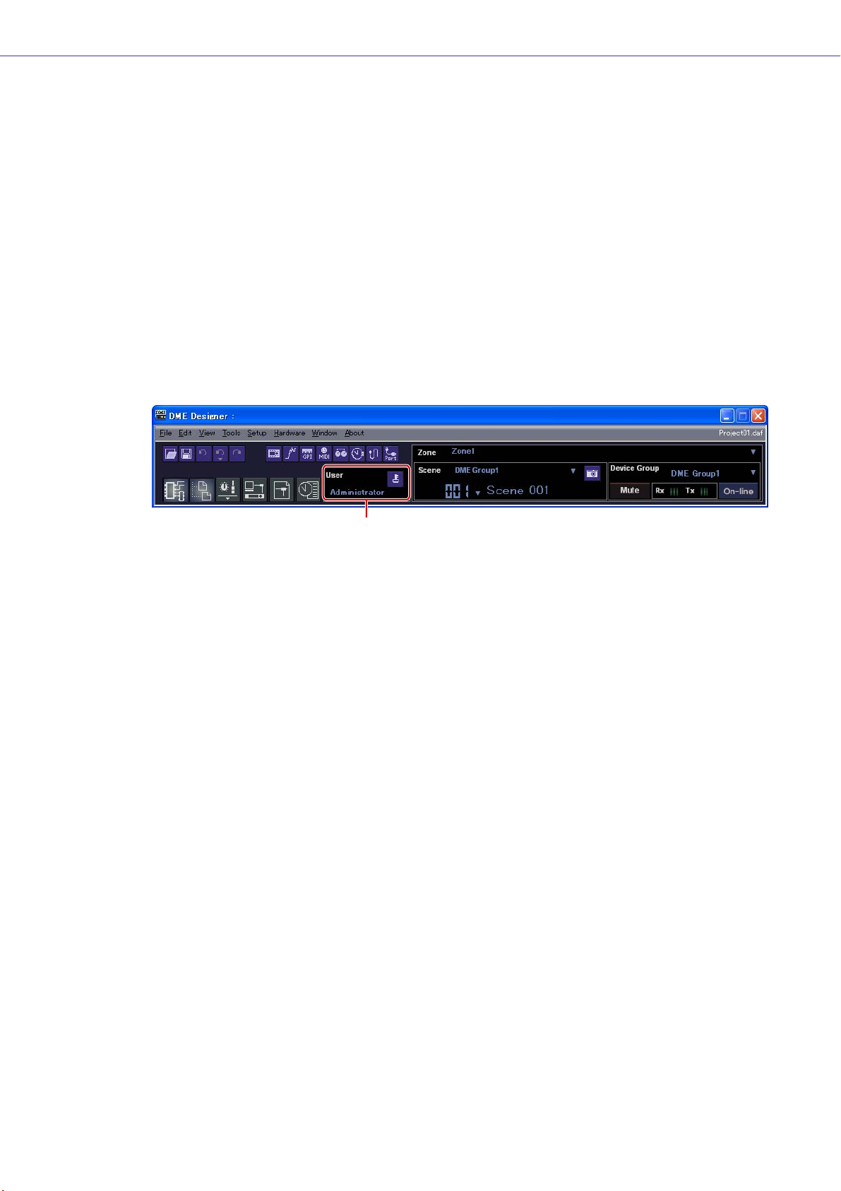
Component Editor
The blocks that are arranged in the configuration window are called “components.” When you
double-click on a component block arranged in the Configuration window, the Component Editor
window will open. There you can edit the parameters for that component. The types of parameters
displayed will differ, depending on the component.
Component Editor
(Stereo Compressor)
Component
Window Operations
Operations in all windows are the same as for normal Windows applications. The windows are
controlled with the [Minimize], [Maximize/Restore], and [Close] buttons at the upper right of the title
bar. DME Designer is closed by clicking the [Close] button on the Main Panel window.
DME Designer Owner’s Manual
27
Page 28
Chapter 2 DME Designer Overview
Users and Security
You can create multiple users in DME Designer and set the functions that are available to each user.
Although users who will design and put together installations must be able to use all the functions of
DME Designer, users who will only operate the system can be restricted to functions that will not allow
them to accidentally change the settings.
DME Designer is used with one user at a time logged on. To change the user, click the [File] menu →
[Log Off] command on the Main Panel window.
About Users
To use DME Designer, you must logon when you start the software. Except for the first time the
software is started or when separate settings are made for the first time, you can logon by specifying
the name and password for a user that has been set as the administrator. The administrator can build
the system as a whole, or apply function limitations that let other people edit. Administrators or other
people that can use DME Designer are called “users.” The user name for the currently logged on user
appears below [User] on the Main Panel window.
Currently Logged On User Name
The default user, named [Administrator], is set to use all of the functions. Immediately after DME
Designer is installed, [Administrator] is the only user, and there is no password set.
Multiple users can be created. When the system administrator creates multiple users, restrictions can
be applied separately for each one of them. A user with restrictions applied can edit using only the
functions the administrator enables for him.
The place to create, setup, and delete users is the “Security” dialog box. See “Scene Manager” on
page 79.
DME Designer Owner’s Manual
28
Page 29
Chapter 2 DME Designer Overview
Logging On
The “Log On” dialog box is displayed whenever the application is started or a user is logged off.
Whenever one user is already logged on, another user cannot be logged on. To log on as another
user, first log off the currently logged on user.
NOTE
If the automatic logon feature is enabled, the “Log On” dialog box will not be displayed when the application is started.
Instead, the auto-logon user will be logged on automatically.
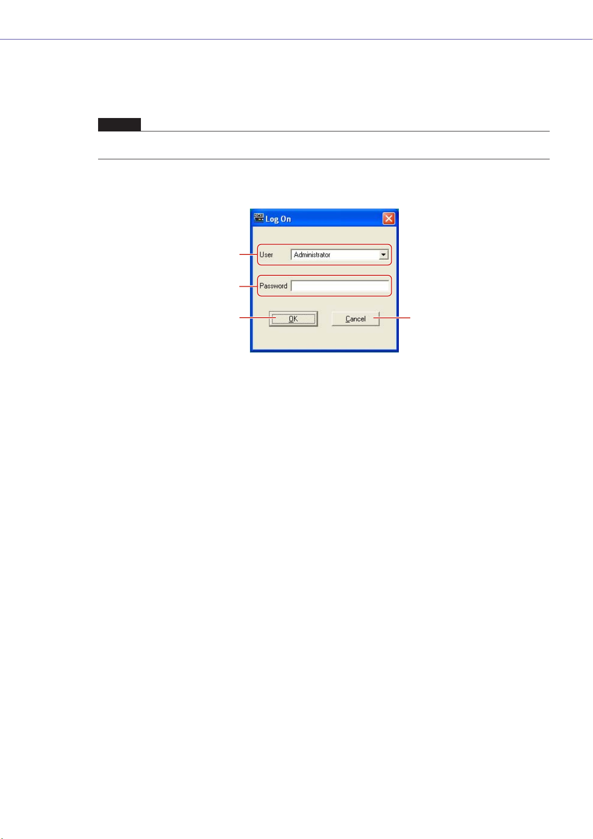
■ The “Log On” dialog box
1
2
3
1 [User]
From the list, select the user you want to log on as.
2 [Password] Box
Enter the password.
3 [OK] Button
Log on as the selected user.
4 [Exit] Button
When the application is started, and the “Log On” dialog box is displayed, there is an [Exit]
button. This closes the application without logging on a user.
5 [Cancel] Button
When the “Log On” dialog box is displayed after a user is logged off, there is a [Cancel] button
instead of an [Exit] button. This cancels the logoff. The original user will continue to be logged
on.
5
■ Logon Procedure
1 Click [▼] at the right of the [User].
A drop-down list of user names will be displayed.
2 Click the user you want to log on.
3 Enter the password into the [Password] box.
When you type in the password box, the characters you enter will display as asterisks (*).
4 Click the [OK] button.
DME Designer Owner’s Manual
29
Page 30
Chapter 2 DME Designer Overview
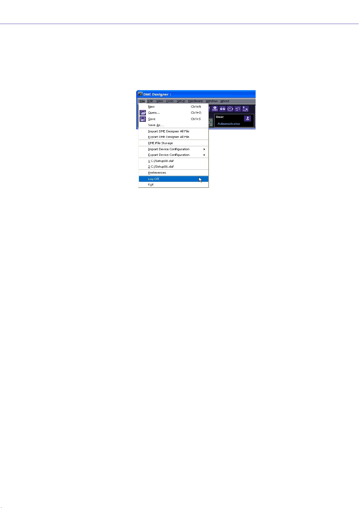
Logging Off
Logoff is used when changing users. When you log off, the document currently being edited is closed,
and the “Log On” dialog box is displayed so you can log on the next user. Log off with the [Log Off]
command on the [File] menu in the Main Panel window.
1 Click the [File] menu ➞ [Log Off] command on the Main Panel window.
Log on the next user in the “Log On” dialog box.
Automatic Logging On
With the auto-logon function, you can have a specified user automatically logged on when the
application is started. If you enable the auto-logon feature, the specified user will be logged on when
the application is started, without displaying the “Log On” dialog box.
Auto-logon is set from the “Security” dialog box. See “Scene Manager” on page 79.
DME Designer Owner’s Manual
30
Page 31

Files Used by the DME DESIGNER
The following files are used by the DME designer application.
Name Description Extension
Project File Stores information relating to the entire project. .daf
DME Data File Stores information for independent DME or SP2060 units. .ddf
Library File Stores component parameters. .cel
Stores user control parameters. .ucl
Stores user module parameters. .uml
Stores user modules. .umf
Stores SP2060 libraries. .llf
Wave List File Stores the Wave File Manager list. .dwl
DME Backup File Stores DME or SP2060 backup data to a file. .dbk
Chapter 2 DME Designer Overview
DME Designer All File Stores the project file, library data files, and all DME Designer settings at
once.
.dme
Project Files
Systems built with DME Designer are saved as project files. Project files have “.daf” as the extension
for their filenames.
These files include settings for the area, zones, device groups, configurations, and each parameter.
Since only one project file can be open at a time, before you can open a second file, the first one must
be closed.
The commands for opening project files, creating new ones, and saving them, are found in the [File]
menu of the Main Panel window.
Creating New Project Files
Project files are created using the [File] menu → [New] command in the Main Panel window.
1 Click [File] menu ➞ [New] in the Main Panel window.
Since the currently open project file must be closed before a new one can be created, a “Project
file has been modified. Save?” dialog box will be displayed.
2 To save the file, click [Yes]. the File Save dialog box will be displayed.
If you click [Yes], the File Save dialog box will be displayed.
A new project file will be created.
DME Designer Owner’s Manual
31
Page 32

Chapter 2 DME Designer Overview
Saving Project Files
Project files are saved using the [File] menu → [Save] and [Save As] commands in the Main Panel
window. The [Save] command overwrites the previously saved version of the file. The [Save As]
command lets you give a new name to the file before saving it. When you save the file with a new
name, you can protect it with a password.
■ The “Save As” Dialog Box
When you click the [File] menu → [Save As] command in the Main Panel window, the “Save As”
dialog box is displayed. Except for some [Security] options, this dialog box is the same as the
normal Windows dialog box for saving files.
1
5
[Up One Level] Button
2
[Create New Folder] Button
3
[Views] Button
4
6
7
@
#
8
9
)
!
1 [Save In]
Specify the folder for saving the file. The folder name is displayed in this box. Click the [▼] on
the right to move to another folder.
The large box below displays the contents of the folder in this box.
2 [Up One Level] Button
Moves to the folder one level higher in the hierarchy.
3 [Create New Folder] Button
Creates a new folder in the folder currently being displayed.
4 [Views] Button
Changes the way the folder content list is displayed. If you click this button, a menu appears
that lets you change the arrangement and display format of the files in the list.
5 List
This box displays the contents of the folder shown in the [Save In] box. Only files belonging to
the type selected in the [Save As Type] box will be displayed.
DME Designer Owner’s Manual
32
6 [File Name] Box
Enter the filename. If the currently open file has already been saved, its name will be already
entered in this box. To save using a different filename, change the name here.
Page 33

Chapter 2 DME Designer Overview
7 [Save as type]
Selects the format for the file you are saving. When saving project files including Wave files set
for Wav File Player, select “Project File with wave (*.daf)”. Otherwise, select “Project File (*.daf)”.
8 [Security]
Protects files with a password. If you check here, you will be able to enter settings in the [ID],
[Password], and [Confirm Password] boxes.
9 [ID] Box
Enter the ID that has been set for the file. The currently logged on user name will be preentered, but you can change it. This need not be the same as a user name.
) [Password] Box
Enter the password that has been set for the file. You can enter up to 256 alphanumeric
characters. The characters you enter will be displayed as asterisks (*) in the [Password] box.
! [Confirm Password] Box
Enter the password once again to confirm it. Enter the same password as was entered into the
[Password] box. The characters you enter will be displayed as asterisks (*), the same as in the
[Password] box.
NOTE
When someone attempts to open a password-protected project file, the application will request an ID and password.
If they are not entered correctly, the file cannot be opened. Be careful to avoid mistakes when entering the ID and
password. The password cannot be reissued and the ID and password cannot be changed. Be careful not to forget
them.
@ [Save] Button
Saves the project file.
If the characters entered into the [Password] and [Confirm Password] boxes were not the same,
a “Password is different” dialog box will be displayed. Click the [OK] button and reenter the
correct password in the [Password] and [Confirm Password] boxes.
# [Cancel] Button
Cancel the file save process.
DME Designer Owner’s Manual
33
Page 34

Chapter 2 DME Designer Overview
■ Saving Project Files
1 Click [File] menu ➞ [Save] in the Main Panel window.
If there is a file already saved with the same name, it will be overwritten.
When saving a project file for the first time, you must name the file before saving it. The “Save
As” dialog box will open, the same as when clicking the [File] menu [Save As] command. Enter
a filename and specify the folder where the file will be saved.
■ Saving a File with a New Name
With the [File] menu [Save As] command in the Main Panel window, you can save the currently
open file with a new filename. When saving for the first time, this creates a new file. A file that has
already been saved with a name will be saved as a separate file.
1 Click [File] menu ➞ [Save As] in the Main Panel window.
The “Save As” dialog box will be displayed.
DME Designer Owner’s Manual
34
2 Enter a filename into the [File name] box.
3 Specify the folder where the file will be saved.
4 Click the [Save] button.
Page 35

Chapter 2 DME Designer Overview
■ Protecting a Project File with a Password
When you save a project file with a new name, you can set a password and protect the file. If a
password is set, an ID and password will be requested when the file is opened.
The security settings for a file cannot be changed by resaving the file with the same name. They
can only be changed when saving the file with a new name using the [Save As] command. Once
set, the ID and password cannot be changed. To change the ID and password for passwordprotected project files, use the [Save As] command to save the file as a new one with a different
name.
1 Click [File] menu ➞ [Save As] in the Main Panel window.
The “Save As” dialog box will be displayed.
2 Place a checkmark for [Security] in the file save dialog box.
3 Enter an ID into the [ID] box.
The name of the currently logged on user will be automatically entered into the [ID] box. To
change it, enter another ID into the box.
When using [Save As] to save a password-protected file, the dialog box will be displayed with
the ID and password boxes automatically filled in with the ID and password that were assigned
to the original file. To change the ID and password, enter new ones into the boxes.
4 Enter the desired password into the [Password] box.
You can enter up to 256 alphanumeric characters for the password. The characters you enter
will be displayed as asterisks (*) in the [Password] box.
5 Enter the same characters into the [Confirm Password] box as were entered into the
[Password] box.
The characters you enter will be displayed as asterisks (*) in the [Password] box.
6 Click the [Save] button.
When saving a password-protected file without changing the name, the same ID and password
will be set (the ID and password cannot be changed).
Using the [Save] command, you cannot password protect an already saved project file that was
not already password protected. To set a password for a file that is not already password
protected, save it as a separate file using the [Save As] command.
DME Designer Owner’s Manual
35
Page 36

Chapter 2 DME Designer Overview
Opening Project Files
Project files are opened using the [File] menu → [Open] command in the Main Panel window. Since
the currently opened project file must be closed before another one can be opened, a “Project file has
been modified. Save?” dialog box may be displayed.
■ [Open] Command
Project files are opened using the [File] menu → [Open] command in the Main Panel window.
1 Click [File] menu ➞ [Open] in the Main Panel window.
A “Project file has been modified. Save?” dialog box may be displayed.
2 Click the [Yes] or [No] button.
The “Open” dialog box will be displayed.
DME Designer Owner’s Manual
36
3 Selects the file to be opened.
4 Click the [Open] button.
Page 37

Chapter 2 DME Designer Overview
Recently Used Files
■ Opening a Project File That Has Security Set
If security is set for a project, the “Enter ID & Password” dialog box will be displayed when you
click the [Open] button in the “Open” dialog box.
Enter the ID and password for the file into the [ID] and [Password] boxes, and click the [OK]
button.
If you enter an incorrect ID or password and click the [OK] button on the “Enter ID & Password”
dialog box, the “Wrong ID or password!” dialog box will be displayed.
Click the [OK] button and enter the correct ID and password the “Enter ID & Password” dialog
box.
■ Opening a Project File from the “Recently Used Files” List
Recently used project files are displayed on the [File] menu in the Main Panel window. If you click
one of the filenames, you can open that project file.
If security is set for a project file, the “Enter ID & Password” dialog box will be displayed if that file is
selected from the recently used files list. Enter the ID and password to open the file.
DME Designer Owner’s Manual
37
Page 38

Chapter 2 DME Designer Overview
■ Double-Click the Icon for the Project File
When you double-click the icon for the project file, the file will open. If DME Designer is not started,
it will start. After logon, the project file will open.
Just as when you use the [Open] command, if DME Designer is already started, the currently open
project file must be closed before another one can be opened. Therefore, a “Project file has been
modified. Save?” dialog box will be displayed.
NOTE
Sometimes the “Project file has been modified. Save?” dialog box will not be displayed.
If security is set for the project file, the “Enter ID & Password” dialog box will be displayed. Enter
the ID and password to open the file.
Closing Project Files
You cannot have multiple project files open simultaneously in DME Designer. To close the currently
open project file, you can create a new project file or open another project file.
DME Data File
You can import or export parameters for a DME or SP2060 that is arranged in a configuration file.
Parameters for a single DME or SP2060 unit in the current configuration (the one being edited) are
saved as a file. Saved parameters can be imported into another project file.
Files with parameters saved in them are called “DME Data Files.” These files have “.ddf” as the
extension for their filenames.
DME Designer Owner’s Manual
38
Page 39

Chapter 2 DME Designer Overview
DME Data Import
This imports DME data file settings into a DME or SP2060 included in the current configuration.
1 Activates the DME or SP2060 configuration layout to be imported.
If multiple configurations are available, the DME or SP2060 configuration layout to be imported can
be selected via the Navigator window.
2 Click the [File] menu in the Main Panel window, and move the mouse cursor over [Import
Device Configuration].
A submenu will be displayed. The DME groups and SP groups included in the current configuration
will be displayed on a submenu.
3 Select the device group to which the DME or SP2060 is to be imported from the submenu.
DME and SP2060 units cannot be used assigned to the same device group.
NOTE
DME and SP2060 units cannot be combined in the same Device Group.
4 On the submenu, click on the DME or SP2060 into which you will import settings.
The “Open” dialog box will be displayed.
5 Select the DME data file and click the [Open] button.
DME Designer Owner’s Manual
39
Page 40

Chapter 2 DME Designer Overview
■ [Import Device Configuration] Submenu
The device groups included in the current configuration, as well as the DME or SP2060 units
included they contain, will be displayed in the [Import Device Configuration] submenu.
Select [Create New Group] to create a new device group
[Create New DME] creates a new DME and imports settings.
NOTE
Only users for whom the [Operation Security] → [Edit] checkbox in the “Security” dialog box has been checked can
import DME data. For information about user security levels, see “Scene Manager” on page 79.
NOTE
If DME data file import was not possible, a “DME file import failed.” message will be displayed.
DME Designer Owner’s Manual
40
Page 41

Chapter 2 DME Designer Overview
DME Data Export
This exports parameters from a DME or SP2060 included in the current configuration and saves them
as a file.
1 Activates the DME or SP2060 configuration layout to be exported.
If multiple configurations are available, the DME or SP2060 configuration layout to be exported can
be selected via the Navigator window.
2 Click the [File] menu in the Main Panel window, and move the mouse cursor over [Export
Device Configuration].
A submenu will be displayed. The DME groups and SP groups included in the current configuration
will be displayed on a submenu.
3 On the submenu, click on the DME or SP2060 from which you will export settings.
The “Save As” dialog box will be displayed.
4 Enter the filename.
Determines whether a selected file type will be exported along with a wave file.
5 Specify the folder where the file will be saved, then click the [Save] button.
NOTE
Library data is not contained in the DME data files exported from SP2060.
Refer to “SP2060 Library Manager” on page 147.
DME Designer Owner’s Manual
41
Page 42

Chapter 2 DME Designer Overview
■ [Export Device Configuration] Submenu
The DMEs or SP2060s included in the current configuration will be displayed on the [Export Device
Configuration] submenu.
Library Files
Component Editor, User Control Editor, and User Module Editor parameters can be stored to and
recalled from library files. Refer to “Library Files” on page 311.
The library data for a single SP2060 unit can be imported or exported as required. Refer to “SP2060
Library Manager” on page 147.
DME Designer All Files
The project file and all DME Designer settings related to the project file can be managed as a DME
Designer All file. DME Designer All files have a “.dme” extension.
DME Designer All files include the settings listed below:
•Project file
• Library files
• User module files
•Wave files
• Picture files
• All DME Designer settings
DME Designer All files are a convenient way to move project data and DME settings you have created
from one computer to another. The DME Designer All import and export commands are provided in the
Main Panel Window [File] menu.
DME Designer Owner’s Manual
42
Page 43

Chapter 2 DME Designer Overview
Importing DME Designer All Files
NOTE
Only users with Administrator access can import DME Designer All files.
1 Click [Import DME Designer All File] in the Main Panel Window [File] menu.
Since the imported data will overwrite the existing DME Designer settings, the confirmation dialog
box shown below will appear.
2 Click [OK] to continue with the import procedure, or [Cancel] to abort the import.
If you click [OK] the “Open” dialog box will appear.
3 Select the DME Designer All file you want to import.
4 Click the [Open] button.
DME Designer Owner’s Manual
43
Page 44

Chapter 2 DME Designer Overview
5 The “Save Project File in DME Designer All File” dialog box will appear, allowing you to
save the imported project file.
For details on saving project files refer to “Saving Project Files” on page 32.
6 If security is set for the file the “Enter ID & Password” dialog box will appear. Enter your ID
and password, and click [OK].
The imported files are stored in the folders listed below.
Name Folder
Project File Specified in step 5.
Library Files The “Library” folder in the folder specified by the [Contents Folder] item in the Main
Panel Window “Preferences” window.
Wave Files The “Wav” folder in the folder specified by [Contents Folder].
Picture Files The “image” folder in the folder specified by [Contents Folder].
DME Designer Owner’s Manual
44
Page 45

Chapter 2 DME Designer Overview
Exporting DME Designer All Files
1 Click [Export DME Designer All File] in the Main Panel Window [File] menu.
The “Select File for Export” dialog box will appear. Check the checkboxes of the files you want to export.
To select all the available files click the [Select All] button, or click [Clear All] to uncheck all the files.
NOTE
• Only wave and image files used by the currently open project file will be displayed. All user module templates will be
displayed under TemplateUserModule.
• The project file and image files will always be exported, so their checkboxes cannot be removed. The DME Designer
settings will also always be exported, so they are not displayed here.
2 Check the file(s) to be exported and click [OK].
The “Save As” dialog box will appear. This is the same as the “Save As” dialog box used when
saving project files, and details can be found in the “Saving Project Files” section on page 32.
3 Enter a file name, destination folder and, if necessary, security settings including ID and
password, then click the [Save] button.
DME Designer Owner’s Manual
45
Page 46

Chapter 2 DME Designer Overview
Configuration Creation Procedure
The configuration is a design diagram that determines the DME configuration. Transferring this data
causes the DME to operate. Follow the procedure below to create a DME Designer configuration.
SP2060 configurations can be selected from scene preset data, but cannot be edited.
NOTE
Configurations can be created only when the DME unit is offline. To transfer the data, you must first go into online status. The
procedure for going online is given later in this document.
1 Creating a New Project.
When you start DME Designer, a new project is created. If another project file is already open, use
the [File] menu → [New] command in the Main Panel window to create a new file.
“Main Panel Window Menu” → [File] menu → [New] (page 58)
2 Zone Settings.
Zone names are set, and zones are added and deleted using the “Zone Manager” dialog box.
See “Adding, Deleting, and Renaming a Zone” on page 277.
3 DME, ICP, External Device Layout.
Position the required DME, ICP, and other external devices in the Designer window, set the device
groups for the DME and ICP units, and set the properties.
See “Device Group Selection” on page 263,
“Designer Window” on page 181,
“Objects” on page 198,
“Design Window Shared Settings and Operations” on page 255.
4 Configuration Settings.
Zone names are set, and zones are added and deleted using the “Zone” dialog box.
See “Adding, Deleting, and Renaming a Configuration” on page 281.
5 Placing Components.
Place components and user modules in the Configuration window.
See “Configuration Window” on page 287,
“User Module” on page 295,
“Types of Components” on page 357.
6 Component Logical Connections.
Use wires to connect the components and user modules you placed in the Configuration window.
See “Drawing and Editing Wires” on page 266.
7 Setting Parameters.
Edit the component parameters in the component editor.
See “Component Editor Window” on page 305.
8 Setting User Defined Button
Parameters can be assigned to function keys F1 through F6 in the DME unit.
See “User Defined Button (User Defined Parameters)” on page 126.
9 Storing Scenes.
Store the scene using the [Tools] menu → [Scene Manager] command in the Main Panel window.
See “IP Address Setup” on page 159.
DME Designer Owner’s Manual
46
Page 47

Online
Chapter 2 DME Designer Overview
You can connect the DME or SP2060 unit to your computer and transfer configurations, scenes and
parameters created in DME Designer into the DME or SP2060 unit. You can also read data from the
DME or SP2060 unit into DME Designer, synchronizing it with the status of the DME or SP2060 unit.
Because Synchronization presupposes that the DME or SP2060 unit can communicate with the
computer where DME Designer is installed, the necessary drivers (USB-MIDI or DME-N Network
Driver) must be installed, and appropriate settings must be made for each driver and for DME
Designer MIDI port.
NOTE
Because there are no scene settings when the DME unit is purchased, the configuration and scene information created in
DME Designer must first be transferred.
NOTE
A maximum of 32 device groups can be online.
NOTE
When combining DME64N/24N and DME Satellite units in a device group, be sure to assign a DME Satellite unit as the
device group master. Synchronization cannot be performed if a DME64N/24N is assigned as the device group master.
1 DME Unit and Computer Connection.
Connect the DME unit and computer using a USB cable or an Ethernet cable.
See separate DME or SP2060 unit Owner's Manual for details.
2 MIDI Driver Installation.
Install the USB-MIDI driver or DME-N Network driver in the computer.
See separate “DME Setup Manual” for details.
3 MIDI Driver Setup.
Make the necessary settings for the MIDI driver installed in the computer. If the driver is set up
already, check the settings before going online.
See separate “DME Setup Manual” for details.
4 MIDI Driver Port Setup.
The MIDI Setup dialog will be displayed if you press the MIDI Setup button on the MIDI Setup
toolbar that is displayed when you start DME Designer Set up the In/Out/Thru ports connected to
the DME.
MIDI Setup button
DME Designer Owner’s Manual
47
Page 48

Chapter 2 DME Designer Overview
NOTE
A maximum of 32 ports can be set.
NOTE
Slave DME64N/DME24N units connected via Ethernet and ICP1 units cannot be set.
NOTE
Only USB 1 is available on DME Satellite.
5 Making MIDI Port Settings in DME Designer.
The port for each device group master can be selected via the “Port” dialog box. If the driver is set
up already, check the settings before going online.
“Port” dialog box (page 149)
6 Storing and Checking Scenes.
When moving online, the lowest scene must be stored. You can check if a scene is stored using the
“Scene Manager” dialog box.
NOTE
Since the SP2060 has scene preset data this confirmation is not necessary.
See “IP Address Setup” on page 159.
7 Recalling Scenes.
When going online, the scene will be recalled. Its scene number must be displayed in [Scene
Number], and its scene name will be displayed in Scene Name. If [--------] is displayed of [Scene
Name], the scene will be recalled.
NOTE
Since the SP2060 has scene preset data this confirmation is not necessary.
NOTE
When the scene device group display mode is “ALL” the scene link name will be displayed. Select a DME group to display
the DME group scene name.
Main Panel Window → “Current Scene” (page 55)
See “Scene Manager” on page 79.
DME Designer Owner’s Manual
48
Page 49

Chapter 2 DME Designer Overview
8 Display the “Synchronization” dialog box.
Click [Synchronization] in the [Tools] menu or the large [Synchronization] button on the toolbar.
When the dialog box opens, a list of connected DME and SP2060 units will be obtained.
DMEs and SP2060s connected to the computer are displayed in the [Network] list.
NOTE
When requesting the “Synchronization” dialog box, a one-time alert will be displayed if the MIDI Port settings have not
been made. After clicking the [OK] button on the alert, a dialog will open. At this time, you can make the needed settings
in the displayed dialog box, and then again display the “Synchronization” dialog box.
9 Device Group Selection
Select the device group to be synchronized from the [Group] list in the [Synchronization] window.
NOTE
Only one device group can be online in one operation.
DME Designer Owner’s Manual
49
Page 50

Chapter 2 DME Designer Overview
10IP Address Selection
The DMEs and SP2060s included in the current device group are displayed in the [Designer] list in
the “Synchronization” dialog box. Click the [IP Address] box, then select the DME or SP2060 unit IP
address that matches the DME or SP2060 currently in the DME Designer.
NOTE
Click [▼] to display the IP addresses of all similar devices in the area.
11Going Online.
Clicking the [Go On-Line] button displays a dialog box where you can decide the synchronization
method.
NOTE
An alert will be displayed if no scene has been recalled.
Click the [DME Designer→Device] direction button.
Transfer of the configuration will begin, and DME Designer will be synchronized with the unit.
If there are many zones, this process may take time.
NOTE
When a configuration has already been transferred to a DME unit, we recommend using the [DME Designer <- Device]
button for synchronization. The transfer time is faster than using the [DME Designer -> Device] button. However, if the
configuration has been edited it is necessary to use the [DME Designer -> Device] button.
DME Designer Owner’s Manual
50
Page 51

Chapter 2 DME Designer Overview
When going online is finished, the [Go On-line] button will be grayed out, and the Main Panel
window [On-Line] button will light up. At this point if the [Store Project File into DME after
synchronization] item is checked, the project file will be automatically transferred to the DME unit
and stored. And if the [Close this window after synchronization] item is checked, the window will
close automatically.
NOTE
It may not be possible to go online if a scene has not been stored when [Recall Safe] is selected.
To go off line, click either the [ON-Line] button in the main panel window, or the [Go Off-line]
button in the “Synchronization” dialog box.
DME Designer Owner’s Manual
51
Page 52

Chapter 3 Main Panel Window
[
Names and Functions of the Windows
The Main Panel window is the main window of DME Designer.
Title Bar
Menu Bar
Tool Buttons (Small)
Tool Buttons (Large)
Current Device GroupCurrent Zone
Current SceneLog On User
[Mute] Button Communication
Status
Title Bar
“DME Designer” is displayed on the title bar.
Menu Bar
Commands that can be executed in the application are collected into categories on the menu bar.
When you click one of the categories, a list of commands is displayed.
Also, the name of the currently open project file is displayed at the right. When a new project file has
been opened, or has not yet been saved, “Untitled” will be displayed for the file name.
Tool Buttons (Small)
Frequently used commands are arranged here as buttons. When a command cannot be used, its
button will be grayed out.
[Open File] Button
[Save File] Button
[Undo] Button
[Undo History] Button
[Redo] Button
DME Designer Owner’s Manual
52
[Port] Button
[User Control Manager] Button
[Clock] Button
[Parameter Link] Button
[MIDI] Button
[GPI] Button
[Word Clock] Button
User Defined] Button
■ [Open File] Button
Opens project files.
→ [Open] on the [File] menu (page 59)
Page 53

Chapter 3 Main Panel Window
■ [Save File] Button
Saves the project file currently being edited.
→ [Save] on the [File] menu (page 59)
■ [Undo] Button
Undoes the most recent edit operation.
→ [Undo] on the [Edit] menu (page 61)
■ [Undo History] Button
Opens the “Undo History” dialog box. Undoes multiple operations.
→ [Undo History] on the [Edit] menu (page 61)
■ [Redo] Button
Restores operations undone with the [Undo] button back to their original condition.
→ [Redo] on the [Edit] menu (page 61)
■ [User Defined] Button
Opens the “User Defined Button” dialog box.
→ See “[User Defined Button]” on page 64.
■ [Word Clock] Button
Opens the “Word Clock” dialog box.
→ See “[Word Clock]” on page 65.
■ [GPI] Button
Opens the “GPI” dialog box.
→ See “[GPI]” on page 63.
■ [MIDI] Button
Opens the “MIDI” dialog box.
→ See “[MIDI]” on page 64.
■ [Parameter Link] Button
Opens the “Parameter Link” dialog box.
→ See “[Parameter Link]” on page 63.
■ [Clock] Button
Opens the “Clock” dialog box.
→ See “[Clock]” on page 66.
■ [User Control Manager] Button
Opens the “User Control Manager” dialog box.
→ See “[User Control]” on page 62.
■ [Port] Button
Opens the “Port” dialog box.
→ See "Port" dialog box on page 65.
DME Designer Owner’s Manual
53
Page 54

Chapter 3 Main Panel Window
Tool Button (Large)
[Synchronization] Button
[User Control] Button
[Event Logger] Button
[Show/Hide Designer] Button
[Show/Hide Navigator] Button
[Event Scheduler] Button
■ [Show/Hide Designer] Button
Displays or hides the Designer window.
■ [Show/Hide Navigator] Button
Displays or hides the Navigator window.
■ [User Control] Button
Works the same as the [User Control] command on the [View] menu. Clicking this button displays a
menu.
User Control will be display there, the user control window will be displayed.
If you click [New User Control], the “New User Control” dialog box opens.
■ [Synchronization] Button
Opens the “Synchronization” dialog box.
→ See “Synchronization” Dialog Box on page 92.
■ [Event Logger] Button
Opens the “Event Logger” window.
→ See “Event Logger” Window on page 72.
■ [Event Scheduler] Button
Opens the “Event Scheduler” dialog box.
→ See “Event Scheduler” Dialog Box on page 95.
Current Zone
Displays the name of the active zone. A list where you can select a zone is displayed when you press
the [▼].
DME Designer Owner’s Manual
54
Page 55

Chapter 3 Main Panel Window
Current Scene
Displays information about the current scene. You can switch between scenes.
[Change displayed Scene]
(displays DME groups/SP2060s)
[Scene Number] [Scene Name] [Scene Manager] Button
■ [Change Display Scene]
Selects the information to be displayed. When “All” is selected scene link information is displayed
in [Scene Number] and [Scene Name]. When a DME group or SP2060 is selected scene
information is displayed in [Scene Number] and [Scene Name].
Refer to “Scene Manager” on page 79 for information on scenes, and “Scene Link Manager” on
page 145 for information on scene linking.
■ [Scene Number]
Displays the number of the current scene or scene link. A list where you can select a scene or
scene link is displayed when you press the [▼]. The EDIT indicator will light when a parameter has
been edited after recalling or storing a scene.
NOTE
Press <Ctrl> key and <+> key simultaneously recall the next scene and press <Ctrl> key and <-> key simultaneously
recall the previous scene. These settings can be changed via the Shortcut keys dialog box (page 150).
■ [Scene Name]
Displays the name of the current scene or scene link.
■ [Scene Manager] Button
Opens the “Scene Manager” dialog box.
DME Designer Owner’s Manual
55
Page 56

Chapter 3 Main Panel Window
[User] (Logged On User)
Currently Logged On
User Name
[Security] Button
■ Currently Logged On User Name
Displays the currently logged on user name.
■ [Security] Button
Opens the “Security” dialog box.
Current Device Group
Displays the name of the currently active device group. Click [▼] to display a list that allows selection
of a different device group.
■ [Mute] Button
Mute OFF Mute ON
Tur ns ON and OFF the DME mute button for the current device group.
To turn it ON, press the <Shift> key while clicking. If you click the button while it is OFF without
pressing the <Shift> key, the following message will be displayed: “Click the Mute Button with the Shift
Key.”
To turn it OFF, click on the button. There is no need to press the <Shift> key.
DME Designer Owner’s Manual
56
Page 57

Chapter 3 Main Panel Window
Communication Status
Displays the status of communication between the group master of the current device group and
the computer.
Message Transmit/Receive Indicator ON-line Button
• [On-line] Button
When the group master of the current device group is connected to a computer, clicking this
button alternately switches the unit's on-line/off-line status. The indicator will light when the
DME unit is on-line.
• Message Transmit/Receive Indicators
[Rx]
Lights when MIDI messages from the group master of the current device group are received by DME
Designer.
[Tx]
Lights when MIDI messages are transmitted from DME Designer to the group master of the current
device group.
DME Designer Owner’s Manual
57
Page 58

Chapter 3 Main Panel Window
Main Panel Window Menu
[File] Menu
■ [New]
Creates a new project. When a new project is created, the current project will be closed.
A confirmation message asking “Project file has been modified. Save?” will be displayed.
[Yes] Button
Saves the currently open project.
If the currently open file was already given a name and saved, that saved file will be overwritten.
The “Save As” dialog box will be displayed for files that have not yet been saved. In this dialog box,
you can name the file when you save it.
[No] Button
Closes the project without saving it. If the file has already been given a name and saved, the most
recently saved version will remain as is. If the project has not been given a name and saved, it will
be lost.
[Cancel] Button
Cancels creation of a new project.
DME Designer Owner’s Manual
58
Page 59

Chapter 3 Main Panel Window
■ [Open]
Opens saved project files. Because the currently open project will be closed, a confirmation dialog
box asking “Project file has been modified. Save?” will be displayed.
When you select this command, the “Open” dialog box will be displayed. Select the project file you
want to open and click the [Open] button.
If security is enabled for the project file, the “Enter ID & Password” dialog box will be displayed.
Enter the ID and password to open the file and click the [OK] button. The project file will open.
■ [Save]
Overwrites an already saved project file with the current changes. If the file is being saved for the
first time, the “Save As” dialog box will be displayed.
→ See “Project Files” on page 31.
■ [Save as]
Saves the current project file as another file with a new name or in a new location. When you select
this command, the “Save as” dialog box will be displayed.
→ See “Project Files” on page 31.
■ [Import DME Designer All File]
Imports DME Designer All files (.dme extension).
→ See "Importing DME Designer All Files" on page 43.
■ [Export DME Designer All File]
Exports the DME Designer All file (.dme extension).
→ See "Exporting DME Designer All Files" on page 45.
■ [Import Device Configuration]
Imports parameters for a device that is arranged in a configuration file.
→ See “DME Data Import” on page 39.
DME Designer Owner’s Manual
59
Page 60

Chapter 3 Main Panel Window
■ [Export Device Configuration]
Exports parameters of a device that is arranged in a configuration file.
→ See “DME Data Export” on page 41.
■ DME File Storage
Opens the “DME File Storage” dialog box.
→ See “DME File Storage” on page 68.
■ Recently Used Files
Displays recently saved files. If you click one of the file names, you can open that file.
■ [Preferences]
Opens the “Preferences” dialog box.
→ See “Preferences” on page 69.
■ [Log Off]
Logs off the currently logged on user. Because the currently logged on user must be logged off
before a new one can be logged on, the “Log On” dialog box will be displayed so you can log on
the next user.
→ See “Users and Security” on page 28.
■ [Exit]
Closes “DME Designer.” A confirmation dialog box asking “Project file has been modified. Save?”
will be displayed. To save, click [Yes]. To close without saving, click [No.]
DME Designer Owner’s Manual
60
Page 61

Chapter 3 Main Panel Window
[Edit] Menu
■ [Undo]
Undoes a single operation. The name of the operation that will be undone by [Undo] is displayed in
the command name. You can also select the commands that come after that.
When [Undo] is not possible, the command will be grayed out.
■ [Redo]
Returns to the status before the [Undo] command was executed. The name of the operation that
will be restored by [Redo] is displayed. You can [Redo] only as many operations as were undone
with the [Undo] command. When [Redo] is not possible, the command will be grayed out.
■ [Undo History]
Opens the “Undo History” dialog box. Undoes multiple operations. Also deletes the history of
operations.
1
1 List
Displays all operations performed so far, in order starting with the oldest. You can select an
operation by clicking on it.
2 [OK] Button
Undoes all operations below the one selected on the list. The operation selected on the list does
not get undone.
2
3
4
3 [Close] Button
Closes the dialog box.
4 [Delete All] Button
Deletes the entire history of operations displayed on the list. When an operation is deleted from
the list, it cannot be undone.
Operations undone from the [Undo History] can be re-executed one-by-one using [Redo].
DME Designer Owner’s Manual
61
Page 62

Chapter 3 Main Panel Window
[View] Menu
■ [Designer]
Displays or hides the Designer window.
■ [Event Logger]
Displays the network event log.
Not displayed if selected while the network event log is showing.
→ See “Event Logger” on page 72.
■ [User Control]
This opens User Control.
The user controls that can be opened by the currently logged on user are displayed on a submenu.
If you click [New User Control] on the submenu, the “New User Control” dialog box opens.
→ See “User Control/User Module Editor” on page 311.
NOTE
Controls that are not available to the currently logged-on user are not shown in the menu.
NOTE
The User Controls that are displayed when the DME Designer is launched can be set on the “User Control Manager”
dialog box.
→ See ""User Control Manager" Dialog Box" on page 86, page 311.
■ [Navigator]
Displays or hides the Navigator window.
DME Designer Owner’s Manual
62
Page 63

[Tools] Menu
Chapter 3 Main Panel Window
■ [Scene Manager]
Opens the “Scene Manager” dialog box.
→ See “Scene Manager” on page 79.
■ [User Control Manager]
Opens the “User Control Manager” dialog box.
→ See “User Control” on page 86, page 311.
■ [Parameter Link]
Opens the “Parameter Link” window.
→ See “Parameter Link” on page 89
■ [Synchronization]
Opens the “Synchronization” dialog box.
→ See “Synchronization (DME Designer and Unit Synchronization)” on page 91.
■ [Event Scheduler]
Opens the “Event Scheduler” dialog box.
→ See “Event Scheduler” on page 95
■ [Wav File Manager]
Opens the “Wav File Manager” dialog box.
→ See “Wav File Manager” on page 102.
■ [GPI]
Opens the “GPI” dialog box.
→ See “GPI” on page 106.
DME Designer Owner’s Manual
63
Page 64

Chapter 3 Main Panel Window
■ [MIDI]
Opens the “MIDI” dialog box.
→ See “MIDI” on page 119.
■ [User Defined Button]
Opens the “User Defined Button” dialog box.
→ See “User Defined Button (User Defined Parameters)” on page 126.
■ [DAW Control]
Opens the “DAW Control” dialog box.
→ See “DAW Control” on page 130.
■ [Remote Control Setup List]
Opens the “Remote Control Setup List” Dialog box.
→ See “Remote Control Setup List” on page 133.
■ [Internal HA Control]
Opens the “Internal HA Control” dialog box.
→ See "Internal HA Control" on page 135.
■ [Parameter List]
Opens the “Parameter List” dialog box.
→ See “Parameter List” on page 138.
■ [Component Lock]
Opens the “Component Lock” dialog box.
→ See “Component Lock” on page 144.
■ [Scene Link Manager]
Allows scene link setup.
→ See "Scene Link Manager" on page 145.
■ [SP2060 Library Manager]
Allows setup of SP2060 libraries.
→ See “SP2060 Library Manager” on page 147.
DME Designer Owner’s Manual
64
Page 65

[Setup] Menu
■ [Port]
Opens the “Port” dialog box.
→ See “MIDI Port Setup" on page 149.
■ [Shortcut Keys]
Opens the “Shortcut Keys” dialog box.
→ See “Shortcut Keys” on page 150.
Chapter 3 Main Panel Window
■ [Security]
Opens the “Security” dialog box.
→ See “Security (Creating Users and Making User Settings)” on page 151.
[Hardware] Menu
■ [Network Setup]
Opens the “Network Setup” dialog box.
→ See “IP Address Serup” on page 159.
■ [Utility]
Opens the “Utility” dialog box.
→ See “Utility” on page 161.
■ [Word Clock]
Opens the “Word Clock” dialog box.
→ See “Word Clock” on page 168.
DME Designer Owner’s Manual
65
Page 66

Chapter 3 Main Panel Window
■ [Monitor Out]
Opens the “Monitor Out” dialog box.
→ See “Monitor Out” on page 170.
■ [Clock]
Opens the “Clock” dialog box.
→ See “Clock” on page 171.
■ [Language]
Opens the “Language” dialog box.
→ See “Language Settings” on page 173.
■ [Backup]
Opens the “Backup” dialog box.
→ See “Backup” on page 174.
■ [Firmware Update]
Updates the DME, SP2060, or ICP1 firmware.
→ See “DME Firmware Update” on page 175.
■ [Device Information]
Opens the “Device Information” dialog box.
→ See "Device Information" on page 178.
DME Designer Owner’s Manual
66
Page 67

Chapter 3 Main Panel Window
[Window] Menu
Displays the open windows. Click a window name to bring that window to the front.
■ [Close All Editor Windows]
Closes all editor windows.
NOTE
Each design windows within the Designer window can be switched using the [Window] menu in the Designer window.
[About] Menu
■ [About DME Designer]
Displays information about this application.
DME Designer Owner’s Manual
67
Page 68

Chapter 3 Main Panel Window
DME File Storage
Allows management of DME files. Project files can be managed on the DME, eliminating the need to
manage them on the computer.Project files can be managed on a DME unit without the need for a
computer. Since project files are necessary to allow synchronization of DME and SP2060 units, we
recommend that you save your project files to the DME unit for enhanced reliability.
Click [DME File Storage] in the [File] menu to display the “DME File Storage” dialog.
NOTE
Does not apply to SP2060 units
Names and Functions
■ Zone List
Select the desired zone and device group and DME from the list.
■ File List
A list of the files stored on the selected DME.
■ [Send] Button
Transfers selected files from the computer to the DME.
■ [Receive] Button
Transfers selected files from the DME to the computer.
■ [Delete] Button
Deletes selected files from the DME.
■ [Close] Button
Closes the dialog box.
NOTE
Synchronization may become impossible if the [Remaining Memory] value (the amount of remaining DME memory)
becomes too small. If this occurs, delete unwanted files to increase the amount of available memory.
DME Designer Owner’s Manual
68
Page 69
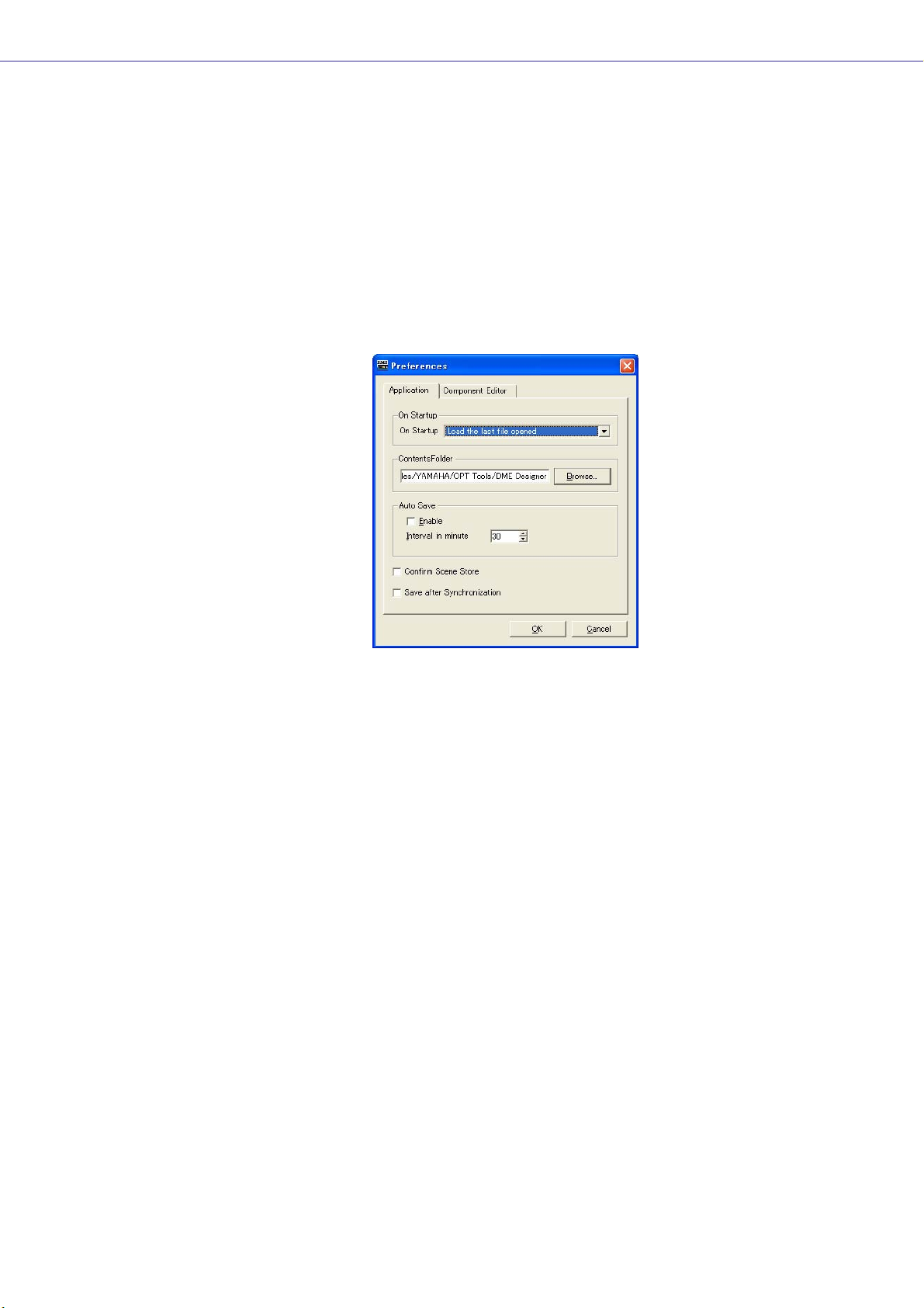
Preferences
When you click the [Preferences] command on the [File] menu in the Main Panel window, the
“Preferences” dialog box is displayed. Here you can make environmental settings for using DME
Designer.
Names and Functions
■ [Application] Tab
Here you can set the general usage environment.
Chapter 3 Main Panel Window
On Startup
Selects the action when the application starts up or a user logs on.
• [Load the last file opened]
Opens the last opened file. If the file cannot be found because it was moved, deleted, or its
name was changed, a new project will be opened.
• [Create an empty file]
Opens a new project.
• [Load File & Synchronization]
Opens the last opened file and synchronizes with the DME or SP2060 unit.
Contents Folder
Specifies the folder where the images used by the Design windows and user controls are stored.
Click the [Browse] button and specify the folder.
DME Designer Owner’s Manual
69
Page 70

Chapter 3 Main Panel Window
Auto Save
Set up the automatic file save feature.
This setting has no effect when the file being worked on has not previously been saved, or the
computer is online.
• [Enable]
Auto save of project files being worked on will occur when checked. The file will be
overwritten, but the Undo history will not be cleared.
• [Interval in minutes]
Specifies the auto-save interval in minutes.
[Confirm Scene Store]
Place a checkmark here to have a confirmation dialog box displayed when storing a scene.
[Save after synchronization]
If a save is performed after the DME Designer is synchronized to the DME or SP2060 unit, the next
synchronization will be significantly faster because one the difference needs to be synchronized.
Check this checkbox to specify auto-save after the DME Designer is synchronized to the DME or
SP2060 unit.
■ [Component Editor] Tab
Sets up operation of the Component Editor knobs, sliders, and edit boxes.
Knob Mode
Sets how the knobs operate.
DME Designer Owner’s Manual
70
• Circular
The knob is dragged following its shape, as though you were drawing a circle.
• Linear
As you drag the knob to the upper, the value increases. Dragging it down decreases the value.
Page 71

Chapter 3 Main Panel Window
Slider Mode
Sets the action that occurs when you click on the scale located under the sliders.
• Ramp
When the fader bar is clicked the knob will move a preset amount in the corresponding
direction.
•Touch
The slider does not move without directly touching it, even if you click the mouse button.
•Jump
The slider jumps to the location where you click.
Edit Box Zoom
When “On” the edit box will enlarge on mouse-over.
Edit Box Font
When “On” the edit box will enlarge on mouse-over.
NOTE
This is the font when the box is enlarged, not the font that is used when the box is at it's smallest size. The text may bleed
beyond the box with some fonts.
NOTE
To make a finer setting, press the <Shift> key while dragging the slider.
If you click a slider while pressing the <Ctrl> key, the setting will return to its default value.
■ Common to All Tabs
[OK] Button
Applies any setting changes and closes the window.
[Cancel] Button
Closes the window without changing any settings.
DME Designer Owner’s Manual
71
Page 72

Chapter 3 Main Panel Window
Event Logger
Click [Event Logger] in the [View] menu to open the “Event Logger” window. This window displays the
DME unit event log, and it allows specifying the log file to be stored on the computer as well as the log
file to be store in the DME unit.
If the window is opened while online the event log is automatically retrieved from the DME unit and
displayed as a list in the “Event Logger” window. New events are displayed in real time while the
window is opened and the system is online. If [Enable Logging] in the “Log Setup” dialog box is ON,
the event data will be written to the computer log file at the same time.
NOTE
Does not apply to SP2060 units.
NOTE
Only users for whom the [View Log Window] checkbox in the “Security” dialog box has been turned ON can display the
“Event Logger” window. The default setting for this parameter is OFF.
NOTE
The events you wish to display in the Event Logger window must be set in advance in the “Event Log List” dialog box.
NOTE
Up to 1,536 events can be stored in the DME unit, while the maximum number of events that can be displayed in the “Event
Logger window is 12,288. When the DME unit even log becomes full, further events cannot be stored. When the DME event
log does become full, use the “Get Log” dialog box to retrieve the event log and then click the [DME Log Clear] button to
clear the DME unit log as necessary. If the “Event Logger” window event log becomes full, the oldest events are
automatically deleted to make room for new events.
Periodically make [Enable Logging] in the “Log Setup” dialog box active so that the event log is saved as a file on the
computer. This operation will automatically clear the DME unit event log.
Names and Functions
DME Designer Owner’s Manual
72
Page 73

■ DME List
• [Date]
Displays the date the event occurred. (Example Display: 2004-08-24)
• [Time]
Displays the time the event occurred.
•[Type]
Displays the event type and icon.
There are three event types:
(Warning): Warning event
(Error): Error event
(Information): Other events
• [Zone]
Displays the name of the zone in which the event occurred.
• [Group]
Displays the name of the device group in which an event has occurred.
• [DME]
Displays the name of the DME in which the event occurred.
Chapter 3 Main Panel Window
• [Event]
Displays the content of the event.
[Log Setup] Button
Displays the “Log Setup” dialog box (page 74). Here you can make Event Log settings.
[Get Log] Button
When offline, this opens the “Get Log” dialog box (page 75). The event log data can be taken from
the DME units, and written to a file on the computer.
[Zone]
Selects the zone, device group and device for which events will be displayed. Only events from the
selected device will be displayed in the window. If [All] is selected, events will be displayed for all.
Display button (Information/Warning/Error)
• [Display Information] Button
Switches between displaying and hiding Information events.
When turned ON, Information events are displayed in the “Event Logger” window.
• [Display Warning] Button
Switches between displaying and hiding Warning events.
When turned ON, Warning events are displayed in the “Event Logger” window.
• [Display Error] Button
Switches between displaying and hiding Error events.
When turned ON, Error events are displayed in the “Event Logger” window.
[Clear Screen] Button
Clears the event log from the “Event Logger” window. The DME unit event log is not cleared.
DME Designer Owner’s Manual
73
Page 74

Chapter 3 Main Panel Window
“Log Setup” dialog box
Click the [Log Setup] button in the “Event Logger” window to display the “Log Setup” dialog box. Here
you can make Event Log settings. These settings apply to the system as a whole.
■ [Enable Logging]
Tur ns the function that writes the event log to a file ON or OFF.
When the checkbox is checked the event log is saved to a file, and the saved event log is cleared
from the DME unit.
If the checkbox is unchecked the DME event log is saved in the DME unit.
When checked, it is set in the [Enable Logging] frame.
Record _ days per log file
Sets the number of days recorded into a single log file. When the specified number of days is
exceeded, a new log file is created, and future log events are recorded there.
When “1” is set for the number of days at 10:00 AM, information will be recorded in the same file
until the next day at 9:59 AM. The number of days counted is cleared and a new log file is created
when the system goes online, or when the “Log Setup” dialog box is closed by changing the
settings such as the number of days or the log file folder, and then clicking the [OK] button.
Automatically delete log files after _ days
When a check is placed here, log files exceeding the specified number of days are automatically
deleted. Specifies the number of days after which log files are automatically deleted.
Log file folder
Specify the folder for saving log files. Clicking the [Browse] button opens the standard operating
system dialog box for specifying folders. Here you can select a folder.
Log files are saved with the following file name: “LOG + Start_Date.txt”.
If there is a file with the same name already in the specified folder, a number will be affixed to the
end of the file name, and it will be saved as a separate file. (Example: LOG20040824-2.txt)
■ [Display Event]
Displays events with checks next to them. This operates together with the [Display Information],
[Display Warning], and [Display Error] buttons in the “Event Logger” window. You can place
checks next to multiple events.
DME Designer Owner’s Manual
74
■ [Display Log Buffer Full Message]
This applies to DME64N/24N units in all zones. When checked, if the DME event log becomes full a
“Log Buffer Full” message will appear on the display of the corresponding DME unit.
■ [Log List Setup] Button
Sets events sent from the DME units. Clicking here displays the “Event Log List” dialog box.
Page 75

Chapter 3 Main Panel Window
■ [OK] Button
Applies any setting changes and closes the window.
■ [Cancel] Button
Closes the window without changing any settings.
“Get Log” dialog box
Click the [Get Log] button in the “Event Logger” window while offline to open the “Get Log” dialog box.
The event log can be retrieved from the DME unit while offline and saved as a file on the computer.
■ DME List
Displays the IP addresses and types of DME units included in the device group. Click the DME
from which to obtain events by placing a check next to it.
■ [Output File Name]
Sets the file name and save location for the log file. Clicking the [Browse] button opens the file
select dialog box, where you can select a file.
■ [DME Log Clear]
Clears (erases) logs in the DME units checked. When you click this button, a confirmation dialog is
displayed.
■ [OK] Button
Applies any setting changes and closes the window.
■ [Cancel] Button
Closes the window without changing any settings.
DME Designer Owner’s Manual
75
Page 76

Chapter 3 Main Panel Window
“Event Log List” Dialog Box
Click the [Log List] button in the “Log Setup” dialog box to open the “Event Log List” dialog box. This
allows selection of the events to be stored in each DME unit. Events not selected here will not be
saved either in the DME unit or to a log file.
■ [Zone]
If you click here, a list will be displayed. Specifies a zone.
■ [DME]
If you click here, a list will be displayed. Specifies DMEs.
■ [Event]
Selects the events to be logged.
■ [Type]
Selects the event type for each event: [Information]/[Warning]/[Error].
■ [GPI OUT]
Specifies the port for event-triggered GPI output. If the same GPI port is specified for multiple
events GPI output will be produced when any of the specified events occurs.
■ [OK] Button
Applies any setting changes and closes the window.
■ [Cancel] Button
Closes the window without changing any settings.
DME Designer Owner’s Manual
76
Page 77

Chapter 3 Main Panel Window
Event Log List
The event logs that can be retrieved from the DME unit as well as their content and countermeasures
are listed below.
Displayed Messages Contents/Countermeasures
Communication between PC and DME ended. Communication between the computer and DME (device group
Communication between PC and DME started. Communication between the computer and DME (device group
Communication between mixer (PM5D) and DME
ended.
Communication between mixer (PM5D) and DME
started.
Communication between master DME and slave
[IP:*.*.*.*] DME ended.
Communication between master DME and slave
[IP:*.*.*.*] DME started.
Scene [***] recalled. Scene number *** has been recalled.
Scene [***] stored. Scene number *** has been stored.
DME Designer to DME unit synchronized. A configuration has been transferred from DME Designer to the
MUTE was turned on. [IP:***] DME (IP Address: *.*.*.*) turned the MUTE function ON.
MUTE was turned off. [IP:***] DME (IP Address: *.*.*.*) turned the MUTE function OFF.
Input gain too high. AD [ChannelNo.*]
Input gain too high. [SlotNo.*, ChannelNo.*]
Input gain too high. CobraNet [ChannelNo.*]
Input gain too high. EtherSound [ChannelNo.*]
master) has stopped. Check cable connections and router/hub
operation.
master) has started.
Communication between the mixing console (PM5D) and DME
(device group master) has stopped. Check cable connections.
Communication between the mixing console (PM5D) and DME
(device group master) has started.
Communication between the device group master DME and
slave (IP Address: *.*.*.*) has stopped. Check cable
connections and router/hub operation.
Communication between the device group master DME and
slave (IP Address: *.*.*.*) has started.
DME unit and synchronized.
The input signal (slot number/channel number will be displayed)
has exceeded the clipping level.
Reduce the input signal level or head amplifier gain.
Output level too high. DA [ChannelNo.*]
Output level too high. [SlotNo.*, ChannelNo.*]
Output level too high. CobraNet [ChannelNo.*]
Output level too high. EtherSound [ChannelNo.*]
Scene store failure. The scene data is protected.
Word clock unlocked. An appropriate word clock is not being received or cannot be
Word clock not synchronized. [Slot] (Slot*,
Channel */*)
Word clock not synchronized. [WC INl]
Word clock not synchronized. [Cascade IN]
Word clock not synchronized. [Cascade OUT]
External word clock changed. [Fs=(*)kHz] The external word clock (frequency: *kHz) has been changed.
Internal word clock changed. [Fs=(*)kHz] The internal word clock (frequency: *kHz) has been changed.
The output signal (slot number/channel number will be
displayed) has exceeded the clipping level.
Reduce the output signal level.
This may have been set by the administrator to prevent
unwanted data changes due to improper operation. To change
this setting turn “Protect” OFF in the “Scene Manager” dialog
box.
detected.
Re-check the word clock connections and the “Word Clock”
dialog box settings.
The received word clock (input connector/slot number/channel
number will be displayed) is not synchronized with the DME
word clock.
Revise the “Word Clock” dialog box settings so that an external
word clock that is in sync with the DME word clock is received.
DME Designer Owner’s Manual
77
Page 78

Chapter 3 Main Panel Window
Displayed Messages Contents/Countermeasures
Communication between DME is busy and load
is applied.
No Battery. The backup battery is completely depleted or not connected.
Low Battery. The backup battery is running low.
MIDI buffer full. The MIDI receive buffer is full.
Flash ROM full. The flash memory used for data storage is full.
GPI IN reception. [PortNo. *, AD(0-1023)= *] A control signal (Level: *) has been received at the GPI IN
GPI OUT transmission. [PortNo. *->HIGH]
GPI OUT transmission. [PortNo. *->LOW]
Panel Unlocked. Panel lock has been disengaged.
Panel Locked. Panel lock is engaged so panel operations cannot be
Heavy network traffic is causing communication delays.
Check the devices connected to the network. It may be
advisable to reduce the number of devices connected to the
network. If the current link mode is 10Base-T, it may be
advisable to upgrade to 100Base-TX
The current settings will be lost and the default settings restored
when the power is turned off. Cease operation immediately and
contact your Yamaha dealer.
This will not affect operation immediately, but if operation is
continued current settings may be lost and the default settings
restored. Contact your Yamaha dealer as soon as possible.
Too much MIDI data may have been received.
Delete unneeded configurations, presets, and/or wave files.
terminal (Port number: *).
A high or low level control signal has been sent via the GPI OUT
terminal (Port number: *).
performed.
Panel operation may have been locked by the administrator to
prevent unwanted data changes due to improper operation. To
unlock the panel press and hold the [CANCEL] button for longer
than 2 seconds.
The power was turned on. DME power has been turned on.
Communication between external AD unit and
DME ended.
External device control buffer full. The receive buffer for control commands from external devices
Invalid password. An incorrect password has been entered via the panel.
Current Settings lost. The memory has been erased and current settings have been
Network hardware error. A network device error has occurred.
Duplicate IP address. Duplicate IP address.
DSP power shortage. Audio input/output has been muted due to insufficient DSP
Communication between the external head amp unit and DME
device has stopped.
Check cable connections.
has become full.
Too much control may have been received.
If you have forgotten the correct password contact your Yamaha
dealer.
lost.
Tr y a scene recall. If that doesn’t rectify the problem contact
your Yamaha dealer.
Contact your Yamaha dealer.
Set IP addresses so that no two devices with the same address
are connected to the network.
resources.
This can occur if a configuration created for 48kHz word clock is
run at 96kHz. To ensure full word clock operation, create
configurations with word clock set to 96kHz.
DME Designer Owner’s Manual
78
Page 79

Scene Manager
Scenes
Configuration contents can be given a name and saved as “Scenes.” Saving scenes is called “Scene
Store.” Parameter settings in the configuration for each site used can be stored multiple times and
recalled and used when needed. There are 999 scene memories available. When a scene is stored,
DME and SP2060 parameters are saved as “preset parameters.” Presets are automatically created
when a scene is stored.
Bringing back a scene (making a scene the current scene) is called “scene recall.” Scenes are
recalled using the [▼] button next to the current scene on the Main Panel window or by using the
“Scene Manager” dialog box.
■ “Scene Manager” Dialog Box
Click either the [Tools] menu [Scene Manager] item or the “Scene Link Manager” window [Scene
Manager] button to open the “Scene Manager” window that allows editing of scene data. Scene
names, security levels, and presets can be changed and copy/pasted as required. The DME
scene memory is comprised of 999 user memories, while the SP2060 has 12 preset memories and
87 user memories. The preset memories are read-only, while settings and changes can be stored
to the user memories as required.
Chapter 3 Main Panel Window
NOTE
Security for the Logged On User
The currently logged on user can store, recall, or edit scenes that have a security level equal to or lower than his or her
own. User security levels are set with the [Edit] → [Store/Recall/Edit] item in the “Security” dialog box.
NOTE
There is no [OK] button or [Cancel] button in the “Scene Manager” dialog box. To close the dialog box, click the [Close]
button at the upper-right of the dialog box.
Changes from storing/recalling scenes or editing, such as changing names or contents, will be applied immediately.
With the dialog box open, you can make the Designer window active and add components or change parameters.
DME Designer Owner’s Manual
79
Page 80

Chapter 3 Main Panel Window
Names and Functions
[Copy] Button
[Insert] Button
[Cut] Button
[Paste] Button
List[Scene Link] Button
[Clear] Button [Recall Safe] Button
[Store] Button
■ DME Group/SP2060 Selection
Selects a DME group or SP2060.
NOTE
The selected DME group or SP2060 is linked with the current device group.
[Detail] Button
[Recall] Button
■ List
Displays the contents of the scene.
Scene No.
Displays the scene number. Click here to select a scene.
Name
Displays the name of the scene. Click the [Name] box to enter a scene name. Up to 18 characters
can be entered.
If the scene has not been stored, “[No Data]” will be displayed. A name can be entered when a
scene is stored. The default names are “Scene001,” “Scene002,” etc. The three-digit number is the
same as the scene number (displayed in [Scene Number]) for the stored scene.
NOTE
The SP2060 display can only display up to 16 single-byte characters. Some characters that appear correctly on the DME
Designer may change when displayed on the SP2060 display. For example, a backslash character will appear as a yen
symbol on the SP2060 display.
DME Designer Owner’s Manual
80
Page 81

Chapter 3 Main Panel Window
Configuration
Displays the configuration name. If the scene has not been stored, a hyphen (-) will be displayed.
Edit Security
Displays the scene edit security levels. Clicking here will display a list where you can change these
security levels. Only levels at or below the security level of the currently logged on user are
displayed in the list. When a user is created, these settings are the same as the new user's security
level, but scene store and edit settings can be set lower.
Recall Security
Displays the scene recall security level. Clicking here will display a list where you can change the
security level. Only levels at or below the security level of the currently logged on user are
displayed in the list. When a user is created, these settings are the same as the new user's security
level, but the scene recall setting can be set lower.
Fade
It sets whether fade is applied (ON) or not (OFF) when a scene is recalled.
When “ON” the faders in fader components will “fade” to their new settings according to the
specified fade mode and fade time when a scene is recalled. This only applies to fader
components.
NOTE
The fade function cannot be simulated in DME Designer.
Fade Mode
Sets the fade mode. You can select “All” or “Selected.”
If you select “All,” all channels using Fader components in their configuration will be affected. Even
when multiple components are used, all channels are targeted. If you select “Selected,” the only
channels affected will be those for which the Fade switch in the component editor has been set to
ON.
NOTE
The Fade switch for each channel is set to OFF by default. The fade effect will not be applied, even if Fade=ON and
Fade Mode=Selected is selected. To apply the effect, you must set the Fade switch to ON for the channels where you
need it.
Fade Time
Sets the fade time: i.e. the time it will take fader parameters to reach their new settings when a
scene is recalled. The changes are smooth and continuous. If only the presets in the recalled
scene are set when that scene is recalled, the volume will be adjusted while the sound from the
previous scene is playing, until the new level is reached If the configuration also changes, the
volume will rise from silence until it reaches the new value. This can be set from zero to 60 seconds,
in 0.1 second increments.
DME Designer Owner’s Manual
81
Page 82

Chapter 3 Main Panel Window
Protect
Tur ns the Protect function ON or OFF.
When ON scene data cannot be deleted, overwritten, edited, or renamed.
NOTE
Right-click in the list and use the contextual menu that appears to set User Defined Button, Program Change, GPI In, or GPI
Out for the scene.
■ [Cut] Button
Cuts the scene selected on the list. The button will be grayed out and cannot be used when the unit
is online or when an SP2060 preset is being used.
■ [Copy] Button
Copies the scene selected on the list. The button will be grayed out and cannot be used when the
unit is online.
■ [Paste] Button
Pastes the contents of the cut or copied scene into the scene selected on the list. Cuts the scene
selected on the list. The button will be grayed out and cannot be used when the unit is online or
when an SP2060 preset is being used. The selected scene will be overwritten.
■ [Insert] Button
Inserts the contents of the cut or copied scene into the location of the scene selected on the list.
The selected scene and those below are moved down by one. For example, if “Door_Open” was
stored as scene number “005,” and selected when the [Insert] button was clicked, the inserted
scene would become scene number “005,” and “Door_Open” would be moved to scene number
“006.”
Click the
[Insert] button
If a scene is stored in the lowest scene on the scene memory list, the button will be grayed out and
the insert function will not be available. Delete the contents of the lowest scene before attempting
to use the insert function.
NOTE
Move the scene data to a different scene memory when you don’t want to erase the contents of the lowest scene.
DME Designer Owner’s Manual
82
Page 83

Chapter 3 Main Panel Window
■ [Clear] Button
Deletes the contents of the scene selected on the list. The button will be grayed out and cannot be
used when the DME unit is online or when an SP2060 preset is being used.
If the preset parameters included in a scene are not used in another scene, a “Delete preset?”
message will be displayed.
If the preset parameters are not needed, click the [OK] button. If you click the [Cancel] button, the
preset parameters will not be deleted. Whichever you click, the scene itself will be deleted.
NOTE
The [Cancel] button on the “Delete Preset?” message does not cancel the [Clear] for the scene. It merely cancels
deletion of the presets.
■ [Recall Safe] Button
Before performing a recall, you can check the contents of the scene selected on the list, and set
components that will not be read. This is used when there are components you do not want
changed by the scene recall.
When you click this button, the “Recall Safe” dialog box will be displayed.
Component NameCheckbox
All components included in the scene will be displayed. There is a checkbox to the left of each
component. Place a check next to the components you do not wish to have read by scene recall
(those you do not wish changed from their current status).
Press the [Select All] button to check all components, or the [Clear All] button to clear the checks
from all components.
Click the [OK] button. The dialog box will close and when the scene is recalled, all components,
except those checked, will be read.
NOTE
The components checked in the “Recall Safe” dialog box are the components that will not be read (that will be ignored).
If you want to read all components, there is no need to make settings in the “Recall Safe” dialog box.
“Recall Safe” is used when you want to keep some components with their current settings, while there are other
components you want to change according to the scene.
DME Designer Owner’s Manual
83
Page 84

Chapter 3 Main Panel Window
■ [Store] Button
Stores the contents of the current configuration into the scene selected in the list. If an empty scene
is selected and the contents stored there, a new scene is created. If a scene is already stored in
the selected scene number, it will be overwritten. If [Confirm Scene Store] is checked on the
[Application] tab of the “Preferences” dialog box, a confirmation dialog box will be displayed
before the scene is stored.
NOTE
The currently logged on user can store scenes at a security level equal to or lower than his or her own only.
NOTE
When the computer and DME/SP2060 unit are online, a scene stored in the DME Designer will also be stored on the DME
or SP2060 unit, regardless of the DME or SP2060 settings.
The DME64N/24N utility display Misc. page [Scene Store] setting only affects store operation from the DME panel
controls.
When a scene is stored, the configuration parameters at that time are saved as “preset
parameters.”Preset parameters are created automatically.
■ [Recall] Button
Recalls the scene selected in the list and makes it the current scene.
NOTE
The currently logged on user can recall scenes at a security level equal to or lower than his or her own only.
■ [Detail] Button
Expands the dialog box and displays a preset parameters list. If you click the preset parameters
list while it is displayed, the preset parameters list will be hidden. When the dialog box is opened,
its status will be the same as the last time it was closed.
NOTE
Not available for SP2060 groups.
[Del] Button
[Store] Button
[New] Button
[Del Unused] Button
DME
preset parameters
DME
DME Designer Owner’s Manual
84
preset parameters
[Detail] Button
Preset parametersList
Page 85

Chapter 3 Main Panel Window
■ Preset parameters List
Displays the preset parameters for each DME unit in the scene selected in the list. When another
scene is selected on the list, the contents of the preset parameters list will be changed.
You can change the preset parameters used in the scene by clicking the radio buttons to the left of
the preset parameters names. You can also create, delete, and store preset parameters or change
their names.
DME
Displays the DME. Below the DME there are [Slot], [Component], and [AD]. If there are preset
parameters below them, a [+] button will be displayed. When you click the [+] it becomes a [-] and
the presets are displayed.
Preset parameters
Displays DME preset parameters.
If you click the preset parameters name, selecting the text that is there, you can change the preset
parameters name. When preset parameters are automatically created when a scene is stored, they
are named “Preset001,” “Preset002,” and so on. preset parameters created with the [New] button
are named “New Preset.”
You can select the preset parameters used in a scene by clicking the radio buttons to the left of the
preset parameters names.
■ [Del] Button
Deletes the preset parameters selected on the preset parameters list.
NOTE
Presets used in a scene cannot be deleted.
■ [Store] Button
Stores the current parameter status in the preset parameters selected in the preset list. The
contents of the selected preset parameters will be overwritten.
■ [New] Button
Stores the current status and creates a new preset parameters. The newly created preset
parameters is named “New Preset1”, “New Preset2” etc.
■ [Del Unused] Button
Deletes unused preset parameters from DME units in the selected device group.
■ [Scene Link] Button
Opens “Scene Link Manager” dialog box.
Refer to “Scene Link Manager” on page 145
DME Designer Owner’s Manual
85
Page 86

Chapter 3 Main Panel Window
User Control
User Controls
You can create an original control by arranging knobs and sliders in the component editor. Controls
you create are called “user controls.”
Those created user controls are displayed in the [View] → [User Control] submenu in the Main Panel
window
Refer to “User Control Editor/User Module Editor” on page 311 for information on user control editing.
“User Control Manager” Dialog Box
When you click [User Control Manager] on the [Tools] menu, the “User Control Manager” dialog box is
displayed. This dialog box displays a list of user controls included in the configuration of the current
device group. There they can be created or deleted. You can also edit the name and security level of
user controls here.
NOTE
Security for the Logged On User
The currently logged-on user can create and edit the user controls of all users at lower security levels as well as the controls
specified for that user. Available user controls are displayed in the User Control manager dialog box that can be accessed
through the [User Control] sub-menu of the main panel window [View] menu.
The user control security level for each user is set with [Operation Security] → [User Control Level] in the “Security” dialog
box. For information about user security, see page 151.
Names and Functions
NOTE
Only controls available to the currently logged on user are shown in the list.
■ Open
If this checkbox is checked, the user control will open automatically when the project file is opened.
DME Designer Owner’s Manual
86
Page 87

Chapter 3 Main Panel Window
■ Name
Displays the names of the user controls. Clicking here will select the characters in the name,
allowing you to change it.
■ Security Level
Displays the security level set for each user control.
Clicking here will display a list where you can change the security level.
■ User
Displays the name of the user specified in User Control.
Clicking here will display a list of the available users.
DME Designer Owner’s Manual
87
Page 88

Chapter 3 Main Panel Window
■ [New] Button
Creates new user controls. Clicking here displays the “New User Control” dialog box.
Enter the User Control name in the [Name] box.
[User Level]/[User Name]
Use the radio buttons to the left to select security-level or user dependent control.
• [User Level]
Select a security level from the drop-down list.
• [User Name]
Check a checkbox.
Click [OK] to create the specified User Control setup.
[Open User Control at startup]
If this checkbox is checked, the user control will open automatically when the project file is opened.
■ [Delete] Button
Deletes the user control selected on the list.
■ [OK] Button
Accepts the changed settings and closes the dialog box.
■ [Cancel] Button
Closes the dialog box without changing the settings.
DME Designer Owner’s Manual
88
Page 89

Parameter Link
About Parameter Links
You can group parameters of the same type and link them. These groups are called “Parameter
Links.” When one parameter in a parameter link group is changed, all parameters in the parameter link
group will change in the same way.
There are three parameter link types: global links, local links and component links. Global links link
parameters for DMEs within a device group. Local links and component links link parameters that are
included for a single DME.
NOTE
Parameters can not apply to multiple groups.
Groups can be created and parameters added to groups in the user control/user module control
editor and component editor. For information about creating parameter links, see “Creating Parameter
Links” on page 354.
You can check the status of parameter links and edit them in the Parameter Link window.
Chapter 3 Main Panel Window
Parameter Link Window
When you click [Parameter Link] in the [Tools] menu, the “Parameter Link” window is displayed. You
can also display the window by selecting [Open Parameter Link] from the context menu displayed in
the user control/user module editor and component editor.
Names and Functions
[Global Link] button/[Local Link] /[Component Link] buttons
[Global Link] button/[Local Link] button/[Component Link] button
Switches the window display.
• Global Link
Links to the parameters of multiple DME units in the zone.
NOTE
Because there is a large load on the network, the maximum number of Global Links will be limited to eight.
• Local Link
Links to the parameters of one DME unit.
• Component Link
Links component parameters of the same type within a single DME unit.
NOTE
Component Link cannot be used with SPX components.
DME Designer Owner’s Manual
89
Page 90

Chapter 3 Main Panel Window
Parameter Link Group List
Displays a hierarchical list of parameter link group and the parameters that belong to them.
When a parameter link group name is selected, the controls that belong to that parameter link
group are selected.
• Group Name
You can select a parameter link group name by clicking on it. Clicking the selected parameter
link group name again will select the characters in the name, allowing you to change it.
Clicking the plus (+) or minus (-) sign to the left of the parameter link group name displays or
hides items that belong to that parameter link group.
You can delete a parameter link group by selecting it and pressing the <Delete> key. You can
also delete a parameter link group by right-clicking on the parameter link group name and
selecting [Delete] in the context menu that is displayed.
• DME Icon
Displays the DME that includes the parameters that belong to a parameter link group. The
components can be displayed or hidden by clicking the plus (+) or minus (-) signs for the
DME icon. The parameters, Min, and Max can be displayed or hidden by clicking the plus (+)
or minus (-) signs for the component.
• Link
Click to turn ON or OFF. Turn OFF to disable parameter linking.
Component linking for multiple parameters can be turned ON or OFF via the contextual menu
that appears when the group name is right-clicked.
•Keep Offset
Click to urn ON or OFF. When “ON” the parameter offset is maintained so that when any
parameter in the group reaches its minimum or maximum value, further decrease or increase
is not possible.
Keep Offset for multiple parameters can be turned ON or OFF via the contextual menu that
appears when the group name is right-clicked.
•Parameter
Displays the parameters that belong to a parameter link group. You can display or hide
minimum and maximum values for a parameter by clicking the plus (+) or minus (-) signs.
You can delete a parameter from a parameter link group by selecting the parameter name
and pressing the <Delete> key.
NOTE
Components for user modules are also listed in a hierarchal display, but if user module security is enabled, the
components are not displayed. However, parameters displayed in the user module editor are displayed here.
DME Designer Owner’s Manual
90
Page 91

Chapter 3 Main Panel Window
Synchronization (DME Designer and Unit Synchronization)
The DME or SP2060 unit and DME Designer are synchronized by Synchronization. The DME or
SP2060 operates according to the configuration and scene information transferred during this
process.
This Synchronization is used when transferring the configuration in DME Designer and when
controlling the DME or SP2060 unit in real time.
NOTE
Because Synchronization presupposes that the DME or SP2060 unit can communicate with the computer where DME
Designer is installed, the necessary drivers (USB-MIDI or DME-N Network Driver) must be installed, and appropriate settings
must be made for the driver and for DME Designer MIDI IN/OUT (page 119).
For information about driver installation and settings, see “DME Setup Manual”. For DME Designer communications settings,
see “Online” (page 47).
NOTE
Because there are no scene settings when the DME unit is purchased, the configuration and scene information in DME
Designer must first be transferred.
NOTE
When combining DME64N/24N and DME Satellite units in a device group, be sure to assign a DME Satellite unit as the
device group master. Synchronization cannot be performed if a DME64N/24N is assigned as the device group master.
NOTE
For information about the online procedure, see “Online” (page 47).
Online and Offline
When a DME or SP2060 unit is connected to the computer and synchronized with DME Designer, its
status is called “Online.” When a DME or SP2060 unit is not physically connected to the computer or
is not synchronized even when it is connected, its status is called “Offline.” You can check the online/
offline status and message transmission in [Communication Status] in the Main Panel window.
■ Online
Sends configurations created in DME Designer to the DME or SP2060 unit and reads data from the
DME or SP2060 unit, so that the DME unit configuration is reflected in the DME Designer
configuration. You can also control the DME or SP2060 in real time from DME Designer. Operations
performed in the DME Designer control editor are reflected in the DME or SP2060 unit, and
operations on the DME or SP2060 side are reflected in DME Designer.
You can not perform configuration editing using the Designer while online.
■ Offline
The communication status becomes offline when editing configurations.
■ Switching Between Online and Offline
You can switch between online and offline in the “Synchronization” dialog box.
NOTE
For information about the online procedure, see “Online” (page 47).
DME Designer Owner’s Manual
91
Page 92

Chapter 3 Main Panel Window
“Synchronization” Dialog Box
When you click the [Synchronization] command on the [Tools] menu, the “Synchronization” dialog box
is displayed. The data from the current device group in the Designer is synchronized with the DME or
SP2060 unit.
Here you can make settings for synchronizing the unit in DME Designer one-on-one with the DME or
SP2060 that actually exists on the network.
Names and Functions
[Go On-line]Button [Go Off-line]Button
[Designer]
Message Area
[Close This window
after synchronization]
checkbox
[Store Project File into DME
after synchronization]
checkbox
■ [Group] List
Allows selection of a device group to be synchronized.
[Network]
DME Designer Owner’s Manual
92
Page 93

Chapter 3 Main Panel Window
■ [Go On-line] Button
This button will be grayed out when the software is online.
Clicking the button displays a dialog box where you can decide the synchronization method.
[DME Designer → Device] button
A consistency check is performed between the data in the current device group and the DME or
SP2060 data, then the communication status changes to online. Transmits data from the DME
Designer to the DME or SP2060 unit and synchronizes the two.
[DME Designer ← Device] button
Data from the DME or SP2060 unit is read into DME Designer. Current data stored in the DME or
SP2060 unit, such as scenes, are read into DME Designer. The configurations in the DME unit and
DME Manager must identical to allow synchronization. Even if the basic configurations are the
same, if one has been edited or changed in any way synchronization will not be possible.
SP2060 configurations cannot be edited, so synchronization is always possible.
NOTE
For details on backing up the DME or SP2060 data as a file, refer to “Backup” on page 174.
■ [Go Off-line] Button
Clicking this button changes from online to offline. While offline, this button will be grayed out.
■ [Close] Button
Closes the dialog box.
■ [Close this window after synchronization] Checkbox
When this checkbox is checked the dialog window will close automatically after synchronization.
■ [Store Project File into DME after synchronization] Checkbox
When this checkbox is checked the project file (.daf extension) will be automatically saved in the
DME unit after synchronization.
DME Designer Owner’s Manual
93
Page 94

Chapter 3 Main Panel Window
■ Designer
The Designer list displays DME or SP2060 units arranged in the currently valid device group in the
DME Designer.
The unit in the DME Designer is matched with a recognized IP address, and they are compared
one-to-one.
Device Name
IP Address Select Box
DME Name
Displays the names of DME or SP2060 units included in the project.
When multiple DMEs and SP2060s of the same type are arranged in a zone window, it is a good
idea to change the name of each one.
IP Address Select Box
Matches the units in the Designer with recognized IP addresses. Click the [IP Address] column [V]
button to see a list of the IP addresses of all devices of the same type in the area. If the unit is a
DME24N, IP addresses for all DME24N devices in the area will be displayed on the list.
If you click the title bar with “IP Address” written on it (pale [▲]/[▼] mark appears), you can line
them up vertically.
■ Network
The devices currently connected to the network are displayed in the Network list. To keep
consistency with the Designer list on the left side, the status of DMEs on the network is displayed.
Device Icon
IP Address
•Device Icon
Displays DME, SP2060 and ICP1 devices connected to the network. The device group master
DME or SP2060 icon is red. Icons for slave DMEs and SP2060s are blue. DMEs and SP2060s
and ICP1 devices with no relation to DMEs and SP2060s in Designer have gray icons.
• IP Address
Displays the DME or SP2060 IP address.
■ Message Area
Displays a message that synchronization is in progress.
DME Designer Owner’s Manual
94
Page 95

Event Scheduler
“Event Scheduler” Dialog Box
When you click [Event Scheduler] in the [Tools] menu, the “Event Scheduler” dialog box is displayed.
This sets the scheduling for events. You can schedule events by specifying the date, time, and the
action to execute. You can set up schedules for events to be executed at a specified time, and events
that are to be repeated periodically. Periodic events are those that repeat each year, month, week, or
day. Up to 50 events can be scheduled. Scheduling can be set separately for each device group.
Settings and changes are sent to the DME unit during online status.
Scene changes, parameter changes, GPI output, and WAV file playback can all be scheduled.
NOTE
Does not apply to SP2060 units
NOTE
Only users for whom the [Edit] checkbox in the “Security” dialog box has been turned ON can edit scheduling settings.
Names and Functions
Chapter 3 Main Panel Window
■ Event View
Displays registered scheduling events. When periodic events (cyclical events) are first displayed
together, they are displayed in order of date.
The order of same-time events can be changed by dragging and dropping.
Click to select an event.
■ [No.]
Displays the event number. Numbers are added from the top in order.
This function will not be executed if the checkbox is not checked.
■ [Name]
Displays the event names. Clicking an event will select it, allowing you to change its name. There is
no limit to the number of characters.
DME Designer Owner’s Manual
95
Page 96

Chapter 3 Main Panel Window
■ [Operation]
Displays the function that will be executed when the event starts.
■ [Date]
Displays the event start date.
Periodic events are displayed as shown below, with an icon and text that indicate a periodic event.
•[January 1 every year]
Each New Year's Day
• [First Monday of January every year]
First Monday in January each year
• [Day 1 every month]
First day of each month
• [Second Monday of every month]
The second Monday of each month.
• [Monday every week]
Each week on Monday
• [Every day]
Every day
■ [Time]
Displays the time for starting the event.
■ Group List
selects the device group for which events are to be specified/displayed. Only events for the
selected device group will appear in the window.
■ [Enable Event Scheduler]
Enables the scheduled events.
■ [Add] Button
Adds an event. Clicking here displays the “Add Event” dialog box. If the maximum of 50 events has
already been registered, this button is grayed out.
■ [Remove] Button
Deletes the event selected on the list. This button is grayed out when no event is selected.
■ [Edit] Button
Lets you edit the selected event. Displays the “Edit Event” dialog box. This button is grayed out
when no event is selected.
DME Designer Owner’s Manual
96
■ [Copy] Button
Copies the selected event. This button is grayed out when no event is selected.
■ [Paste] Button
Pastes the copied event. The event is added. This button is grayed out when no event has been
copied.
Page 97

Chapter 3 Main Panel Window
■ [Clock setup] Button
Opens the “Clock” dialog box to set the DME internal clock.
→ See "Clock" on page 171.
■ [Apply] Button
Applies any current setting changes.
■ [OK] Button
Applies any setting changes and closes the window.
■ [Cancel] Button
Closes the window without changing any settings.
[Add Event (Edit Event)] Dialog Box
The dialog box is displayed when you click on the [Add] or [Edit] button in the “Event Scheduler”
dialog box. Here you can add or edit a scheduling event.
■ [Event Name] Box
Enter the event name. There is no limit to the number of characters.
DME Designer Owner’s Manual
97
Page 98

Chapter 3 Main Panel Window
■ [Event Operation]
Set the operation that is executed when the event starts.
[Operation]
When you click this button, a list of events is displayed. Specify the operation that is executed
when the event starts.
The following four items are on the list:
• [Scene Change]
Changes the scene.
•[Parameter Value Edit]
Changes a parameter.
NOTE
If user module security is enabled, the components are not displayed. However, parameters displayed in the user
module editor are displayed here.
• [GPI Out]
Sends GPI output.
• [Play Wav File]
Allows initiation of Wave file playback.
[Operation Setting]
The content changes according to the event selected for [Operation].
• When [Scene Change] is selected:
Select the scene to be recalled from the [Scene] list. Stored scenes are displayed in the list.
• When [Parameter Value Edit] is selected:
[Scene]
Select a scene from the list.
If the DME unit's current scene differs from the scene specified in event scheduling, the scheduled
scene will be recalled. If the DME unit's current scene is the same as the scene specified in event
scheduling, the scheduled scene will not be recalled.
DME Designer Owner’s Manual
98
[DME Unit]
From the list, select the DME unit to which this scheduled event will apply. The DMEs included in the
zone are displayed in the list.
Page 99

Chapter 3 Main Panel Window
[Component]
Select the component that has the parameter to be changed. The list displays the components
arranged for the DME that is selected in the [DME Unit] box.
[Parameter]
Select the parameter that will change. Parameters for the component that is selected in the
[Component] box are displayed in a list.
[Value]
Set a value for the parameter. Change the parameter using the spin buttons or the slider on the right.
• When [GPI Out] is selected:
[DME]
From the list, select the DME where you will be making settings.
[Port1]/[Port2]/[Port3] ...
Set [ON], [OFF], or [---] for each port. If it is set to [OFF], the [LOW→HIGH] port outputs
[HIGH→LOW] signal, the [HIGH→LOW] port outputs [LOW→HIGH] signal.
• When [Play Wav File] is selected:
[Scene]
Select a scene from the list.
[Wave]
Select a Wave file from the list.
Wave files set by the Wav File manager can be specified. Files can not be selected unless a Wav
Player is included in the DME configuration.
DME Designer Owner’s Manual
99
Page 100

Chapter 3 Main Panel Window
■ [Event Schedule]
Set the year/month/date to start the event.
Calendar
Sets the date the event will start.
Change the year and month using the [<] and [>] buttons. Click on a day to set that date. February
29 can be set on the calendar, where it appears every four years (each leap year).
[Time]
Sets the time the event will start.
Click the hour and minute, then set numerical values using the spin boxes.
Only the time is set for periodic events.
[Repeating Event]
When a check is placed here, the event becomes a periodic event, and the calendar is ignored.
•[Year]/[Month]/[Week]/[Day]/[Hour]
Set the period for the event, using the radio buttons to the left.
• [Day]/[Day of the week]
Set the conditions on the right side. Select [Day]/[Day of the week], and set the date and other
information. The items that can be set vary according to the selected period.
When the event period is [Year]
All settings can be made.
When the event period is [Month]
If [Day] is selected, only the date can be set.
If [Day of the Week] is selected, settings such as “the third Sunday” or “the first Monday” can be
made.
When the event period is [Week]
Only [Day Of The Week] can be selected. Set the day of the week.
DME Designer Owner’s Manual
100
When the event period is [Day]/[Hour]
Condition settings on the area on the right are not needed.
[Exception] Button
Opens the “Event Exceptions” dialog.
[OK] Button
Applies any setting changes and closes the window.
[Cancel] Button
Closes the window without changing any settings.
 Loading...