

Page 1
EN
How to Use This Reference Manual
The CL5/CL3/CL1 Reference Manual (this document) allows you
to search for terms and take advantage of links in the text.
Searching for terms
To search for a term, use the search function of the software
you're using to view this document.
If you're using Adobe Reader, enter the term in the search box
and press the <Enter> key of your computer keyboard to search
for occurrences of that term.
Displaying the next/previous view
If you're using Adobe Reader, you can jump to the previous/next
view in your viewing history. This is a convenient way to jump back
to the previous page after you've used a link to jump to a different
page.
Reference Manual
Using the Function Tree
A function tree for the CL series is provided on page 4 and
following. You can use this function tree to find the page that
explains an on-screen display or function.
Page 2

Table of contents
Table of contents
How to Use This Reference Manual .......................................................................... 1
Function Tree ............................................................................ 4
SELECTED CHANNEL section ...................................................... 6
Operations in the SELECTED CHANNEL Section ....................................................... 6
Centralogic section ................................................................. 12
Operations in the Centralogic section .................................................................... 12
Input and output patching..................................................... 16
CL console internal patching and Dante audio network patching .......................... 16
Changing the input patching ................................................................................ 17
Changing the output patching .............................................................................. 18
Inserting an external device into a channel ............................................................ 20
Directly outputting an INPUT channel ................................................................... 23
Input channels ........................................................................ 26
Signal flow for input channels................................................................................ 26
Specifying the channel name/icon ......................................................................... 27
HA (head amp) settings ......................................................................................... 29
Sending the signal from an input channel to the STEREO/MONO bus ................... 33
Sending a signal from an input channel to a MIX/MATRIX bus .............................. 37
Channel name display indication ........................................................................... 40
Correcting delay between channels (Input Delay).................................................. 40
Surround output for input channels....................................................................... 44
Channel library operations..................................................................................... 48
OUTPUT channels.................................................................... 49
Signal flow for output channels ............................................................................. 49
Specifying the channel name/icon ......................................................................... 50
Sending signals from MIX channels to the STEREO/MONO bus ............................. 51
Sending signals from MIX channels and STEREO/MONO channels to
MATRIX buses............................................................................................. 53
Correcting delay between channels (Output Delay)............................................... 56
Channel library operations..................................................................................... 57
EQ and Dynamics ..................................................................... 58
Using EQ ................................................................................................................ 58
Using dynamics ...................................................................................................... 61
Using the EQ/Dynamics libraries............................................................................. 64
Channel Job ............................................................................. 65
DCA group............................................................................................................. 65
DCA Roll-out function ............................................................................................ 68
Mute group............................................................................................................ 70
Using the Recall Safe function................................................................................. 73
Channel Link function ............................................................................................ 76
Copying, moving, or initializing a channel.............................................................. 81
About Mix Minus.................................................................................................... 84
Scene memory ......................................................................... 86
Storing and recalling scenes ................................................................................... 86
Editing scene memories.......................................................................................... 90
Using the Global Paste function.............................................................................. 93
Using the Focus Recall function .............................................................................. 94
Using the Fade function.......................................................................................... 96
Outputting a control signal to an external device in tandem with scene recall
(GPI OUT) ................................................................................................... 98
Playing back an audio file that links to a scene recall............................................... 99
Using Preview mode............................................................................................. 100
Monitor and Cue functions ................................................... 102
Using the Monitor function .................................................................................. 103
Using the Cue function......................................................................................... 109
Talkback and Oscillator......................................................... 114
Using Talkback ..................................................................................................... 114
Using the Oscillator function ................................................................................ 116
Meters.................................................................................... 119
Operations in the METER screen ........................................................................... 119
Using an MBCL meter bridge (optional) on the CL3 or CL1 console ..................... 123
Graphic EQ, Parametric EQ, Effects, and PREMIUM RACK..... 124
About the virtual rack ........................................................................................... 124
Virtual rack operations.......................................................................................... 125
Graphic EQ operations ......................................................................................... 128
About AUTOMIXER............................................................................................... 135
Editing the internal effects .................................................................................... 137
Effects and tempo synchronization ....................................................................... 143
2
Reference Manual
Page 3

Table of contents
Using the Premium Rack...................................................................................... 144
Using the graphic EQ, parametric EQ, effect, and Premium Rack libraries ............ 153
I/O devices and external head amps .................................... 154
Using an I/O device ............................................................................................. 154
Remotely controlling an R series unit ................................................................... 156
Remotely controlling an amp............................................................................... 159
Remotely controlling WIRELESS unit..................................................................... 160
Using an external head amp ................................................................................ 160
MIDI....................................................................................... 165
MIDI functionality on the CL series console.......................................................... 165
Basic MIDI settings .............................................................................................. 165
Using program changes to recall scenes and library items.................................... 168
Using control changes to control parameters....................................................... 170
Using Parameter Changes to control parameters ................................................. 172
Recorder................................................................................ 173
About the USB memory recorder ......................................................................... 173
Assigning channels to the input/output of the recorder ....................................... 173
Recording audio to a USB flash drive.................................................................... 175
Playing back audio files from a USB flash drive ..................................................... 177
Editing the title list............................................................................................... 178
Recording or playing back using a computer DAW .............................................. 179
Using the CL console with Nuendo Live............................................................... 182
Setup ..................................................................................... 186
About the SETUP screen....................................................................................... 186
User settings ........................................................................................................ 188
Preferences .......................................................................................................... 195
USER DEFINED keys ............................................................................................. 197
Functions that can be assigned to USER DEFINED keys ........................................ 199
USER DEFINED knobs........................................................................................... 203
Functions that can be assigned to USER DEFINED knobs ...................................... 204
Assignable encoders ............................................................................................ 206
Functions that can be assigned to the assignable encoders .................................. 207
GAIN/PAN/ASSIGN knob (assignable encoder) functions ..................................... 208
Custom fader bank .............................................................................................. 208
Master fader ........................................................................................................ 209
Custom fader bank functions ............................................................................... 210
Console Lock ....................................................................................................... 210
Saving and loading setup data to and from a USB flash drive............................... 211
Formatting a USB flash drive................................................................................ 217
Word clock and slot settings ................................................................................ 218
Using cascade connections ................................................................................... 220
Basic settings for MIX buses and MATRIX buses.................................................... 223
Switching the entire phantom power supply on/off.............................................. 224
Specifying the brightness of the touch screen, LEDs, channel name displays,
and lamps ................................................................................................. 224
Setting the date and time of the internal clock ..................................................... 225
Setting the network address ................................................................................. 225
Dante audio network settings ............................................................................... 226
Using GPI (General Purpose Interface) .................................................................. 237
Help function......................................................................... 243
Loading a Help/text file from a USB flash drive ..................................................... 243
Viewing Help........................................................................................................ 243
Using USER DEFINED keys to recall Help directly................................................... 244
Other functions ..................................................................... 245
Initializing the unit to factory default settings ....................................................... 245
Adjusting the detection point of the touch screen (Calibration function) .............. 245
Adjusting the faders (Calibration function) ........................................................... 246
Fine-tuning the input and output gain (Calibration function) ............................... 246
Adjusting the channel color (Calibration function)................................................ 248
Adjusting the brightness of the channel name display .......................................... 248
Adjusting the contrast of the channel name display.............................................. 249
Initializing the console settings and Dante audio network settings........................ 249
Warning/Error Messages ...................................................... 250
Index...................................................................................... 253
3
Reference Manual
Page 4

Function Tree
Function Tree
Page numbers in parentheses ( ) are the page numbers of the
Owner's Manual(booklet).
Main
SELECTED CHANNEL 6
OVERVIEW 13
FUNCTION ACCESS AREA (18)
CHANNEL PARAMETER
PATC H/NAME 18, 28, 50
GAIN/PATCH 29
1ch 29
8ch 30
CH1-48 32
CH49-72/ST IN 32
OUTPUT
INPUT DELAY 40
8ch 41
CH1-48 42
CH49-72/ST IN 42
DELAY SCALE 41
INSERT/DIRECT OUT 21
1ch 21, 24
8ch 22, 24
HPF/EQ 58
1ch 58
8ch 60
CH1-48 60
CH49-72/ST IN 60
OUTPUT 60
DYNAMICS 61
1ch 61
KEY IN SOURCE SELECT 62
8ch 63
CH1-48 64
CH49-72/ST IN 64
OUTPUT 64
Indication only
CHANNEL PARAMETER
MIX SEND/MATRIX SEND 38
TO STEREO/MONO 51
8ch 51
CH1-48 52
CH49-72/ST IN 52
OUTPUT 52
SURROUND 44
LIBRARY
CHANNEL LIBRARY 48
EQ LIBRARY 64
DYNAMICS LIBRARY 64
GEQ/PEQ LIBRARY 153
EFFECT LIBRARY 153
Portico5033/Portico5043/U76/Opt-2A/
EQ-1A/DynamicEQ LIBRARY
DANTE INPUT PATCH LIBRARY 155
RACK
VIRTUAL RACK 125
RACK MOUNTER 128
GEQ EDIT 129
RACK LINK 129
EFFECT RACK 139
EFFECT EDIT 139
EFFECT TYPE 139
PREMIUM RACK 144
PREMIUM RACK MOUNTER 145
PREMIUM RACK EDIT 146
AUTOMIXER 135
PARAMETRIC EQ 132
I/O DEVICE
DANTE PATCH 154
DANTE INPUT PATCH 155
OUTPUT PATCH 156
153
I/O DEVICE
I/O 156
AMP 159
WIRELESS 160
EXTERNAL HA 162
EXTERNAL HA RACK 162
EXTERNAL HA EDIT 162
EXTERNAL HA PORT SELECT 163
MONITOR
MONITOR 103
CUE 112
MONITOR 105
OSCILLATOR 117
TALKBACK 115
METER
INPUT METER 119
OUTPUT METER 119
SETUP
USER SETUP 186
PREFERENCE 195
USER DEFINED KEYS SETUP 197
USER DEFINED KEY SETUP (List) 197
USER DEFINED KNOBS SETUP 203
USER DEFINED KNOB SETUP (List) 203
ASSIGNABLE ENCODER SETUP 206
CUSTOM FADER BANK/MASTER FADER 209
FADER ASSIGN SELECT 208
USER LEVEL/CREATE USER KEY 189
CREATE KEY 190
SAVE KEY 193
LOGIN 191
SAVE/LOAD 211
WORD CLOCK/SLOT SETUP 218
CASCADE IN/OUT PATCH 221, 222
4
Reference Manual
Page 5

SETUP PATCH
OUTPUT PORT 56
MIDI/GPI 165, 237
MIDI SETUP 166
PROGRAM CHANGE 168
CONTROL CHANGE 171
GPI 238
FADER START 241
BUS SETUP 223
CONSOLE LOCK 210
DATE/TIME 225
NETWORK 226
DANTE SETUP 226
SCENE
SCENE LIST 88
GLOBAL PASTE 93
Fade time 97
SONG SELECT 100
FOCUS RECALL 95
PORT SELECT
CH SELECT 20, 126, 174, 209
Others
CONFIRMATION 196
SOFT KEYBORD (21)
LOGIN 191
Startup Menu
MODE SELECT 245
INITIALIZE ALL MEMORIES 245
INITIALIZE CURRENT MEMORIES 245
TOUCH SCREEN CALIBRATION 245
INPUT PORT TRIM 247
OUTPUT PORT TRIM 247
SLOT OUTPUT TRIM 247
FADER CALIBRATION 246
LED COLOR CALIBRATION 248
Function Tree
23, 25, 106, 113,
155, 222
RECORDER
USB 173
NUENDO LIVE 182
CH JOB
CH LINK MODE 77
DCA GROUP ASSIGN 66
MUTE GROUP ASSIGN 66
RECALL SAFE MODE 74
CH COPY MODE 81
CH MOVE MODE 83
CH DEFAULT MODE 84
NOTE
• The explanations in this reference manual will use the CL5.
• In the case of the CL3/CL1, some screens will not show
channels and faders that do not exist on those models.
5
Reference Manual
Page 6
SELECTED CHANNEL section
Channel number
Channel name
SELECTED CHANNEL section
The SELECTED CHANNEL section located at the left of the display corresponds to a channel
module of a conventional analog mixer, and allows you to use the knobs on the panel to set
all the major parameters of the currently-selected channel.
Operations in this section will affect the channel that was most recently selected by its [SEL]
key. If you have assigned an ST IN channel or STEREO channel to a single channel strip,
either the L or the R channel will be selected, and the major parameters for L and R channels
will be linked.
Operations in the SELECTED CHANNEL Section
Follow the steps below to perform operations in the SELECTED CHANNEL section.
STEP
1. Use the [SEL] key in the top panel INPUT section, ST IN section, or the STEREO/
2. Press one of the knobs in the SELECTED CHANNEL section.
3. Use the knobs of the SELECTED CHANNEL section and the buttons in the SELECTED
CHANNEL VIEW screen to edit the parameters of the selected channel.
• Even if a different screen is selected, the channel selected with the
[SEL] key can be set using the knobs of the SELECTED CHANNEL
section. In this case, a window indicating the value of that parameter will
appear on screen when you operate a knob.
MONO section, to select the channel to control.
NOTE
• To select a MIX or MATRIX channel, use the Bank
Select keys to recall the desired channel to the
Centralogic section, and then press the [SEL] key for
the desired channel.
• The number and name of the currently-selected
channel is shown in the channel select field located in
the Function Access Area of the touch screen.
• If an ST IN channel or STEREO channel has been
assigned to a single channel strip, you can switch
between L and R by repeatedly pressing the same
[SEL] key.
• You can also switch channels by pressing the channel
select field located in the Function Access Area.
Press the left side of the field to select the preceding channel. Press the right side of the field to
select the next channel.
• If you have turned on the option“POPUP APPEARS WHEN KNOB(S) PRESSED” on the
PREFERENCE tab (accessed by pressing the SETUP button, then the USER SETUP button),
pressing a knob repeatedly will open or close the screen (1 ch).
6
Reference Manual
Page 7

SELECTED CHANNEL section
1
1
2
3
SELECTED CHANNEL VIEW screen
SEND field
In this field, you can view the send level and pre/post from the channel
to each MIX/MATRIX bus. You can also switch the on/off status of the
send signals. The view and the function of the knobs and buttons in
the SEND field vary depending on whether a pair of bus channels
(odd-numbered and even-numbered) are comprised of two mono
channels or a stereo channel.
1 Ta bs
Enable you to select a group of 16 output bus channels to be
displayed in the SEND field.
• MIX1-16 tab............................ displays MIX buses 1-16.
• MIX17-24/MATRIX tab ........... displays MIX buses 17-24 and
MATRIX buses 1-8.
If the destination bus channels are two mono channels:
1 SEND knob
Adjusts the send level to the corresponding bus.
2 PRE indicator
The type of the corresponding bus is indicated. If the type is VARI [PRE EQ] or VARI [PRE
FADER], and if the PRE button on the MIX SEND 8ch screen is turned ON, the type is
displayed.
3 ON button
Switches the send signal to the corresponding bus on or off.
If the destination bus is a stereo channel:
1
2
3
1 SEND/PAN knob
The right-hand knob adjusts the level of the signal sent to a pair of bus channels (evennumbered and odd-numbered). The left-hand knob adjusts the pan and balance of the
same signal.
2 PRE indicator
The type of the corresponding bus is indicated.
3 ON button
Switches the send signal to the two buses on or off.
NOTE
• If the type of the destination bus is set to FIXED, controllers 2 and 3 mentioned above will not
be displayed.
• Press the SEND knob or PAN knob on screen to open the SEND 8ch window.
7
Reference Manual
Page 8

SELECTED CHANNEL section
2
1
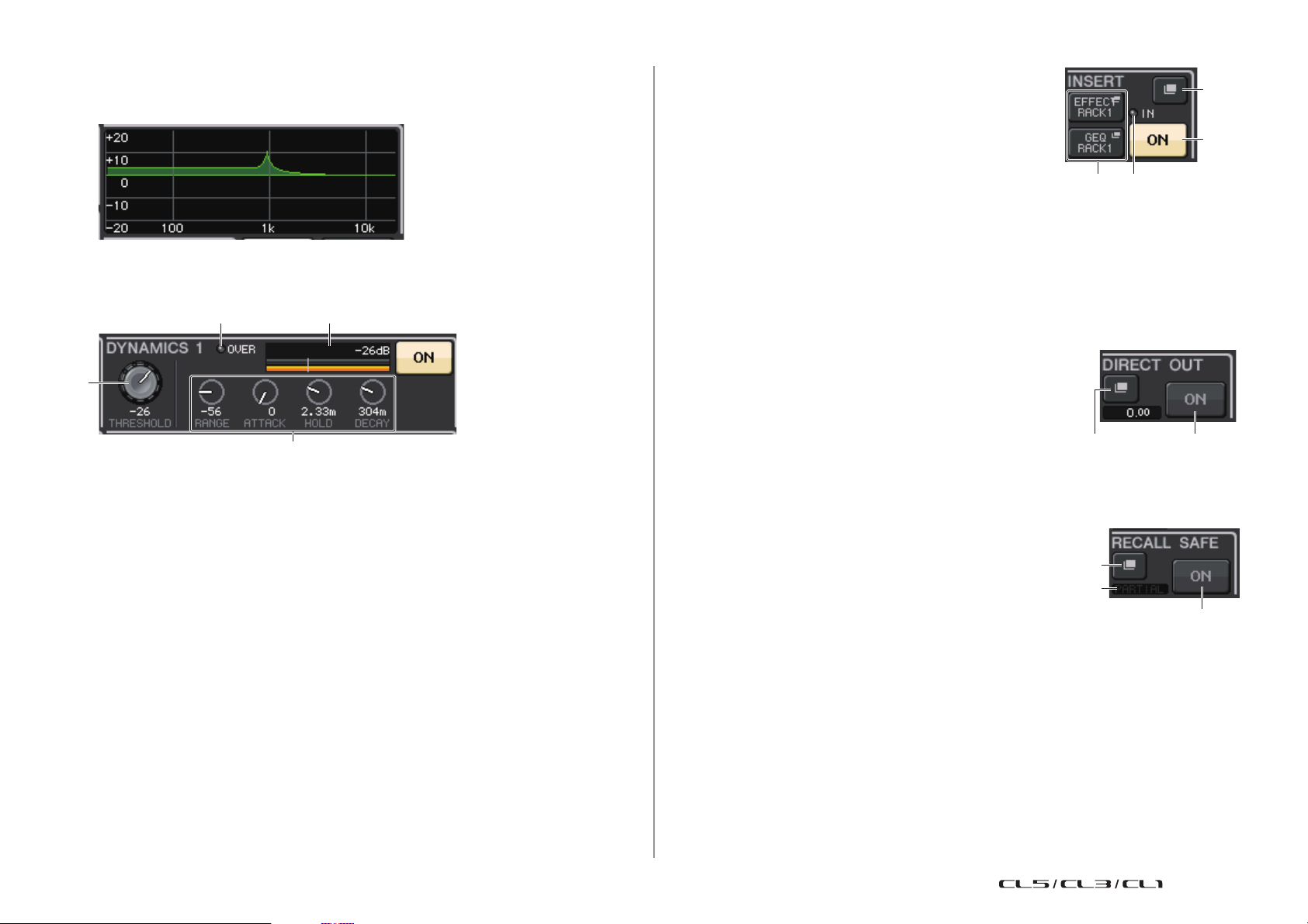
GAIN/PATCH field
This field enables you to make HA (head amp) analog or digital gain settings. You can also
view the operational status of the head amp.
1 GAIN knob
Sets the analog gain/digital gain of the head amp.
Press the knob to open the GAIN/PATCH 1ch window.
2 GC indicator
Indicates the fixed gain value output to the audio
network if the Gain Compensation function is turned
on.
3 OVER indicator
Warns you when the signal is clipping.
2
5
41763
8
4 Ø (Phase) indicator
Indicates the status of the phase setting.
5 +48V indicator
Indicates the phantom power (+48V) on or off status for the head amp.
6 HPF ON indicator
Indicates the HPF on/off status of the external head amp.
7 AG-DG LINK indicator
Indicates a link between the analog gain and digital gain of the head amp.
8 Digital/Analog gain value
If analog gain is assigned to the GAIN knob, the digital gain value is shown here. If digital
gain is assigned to the GAIN knob, the analog gain value is shown here.
NOTE
• For an input channel that is patched to an input that has no head amp, 1, 2, 5, 6, and 7
will not be shown. For an output channel,
• If a GAIN KNOB FUNCTION is set to DIGITAL GAIN in the USER SETUP PREFERENCE
screen, the digital gain knob will appear for
For details, refer to “HA (head amp) settings” (page 29).
1 - 7 will not be shown.
1, and 2, 5, 6, and 7 will not be displayed.
PAN/BALANCE field
This field enables you to switch the on/off status of the signal sent from the selected channel
to the STEREO/MONO bus, and adjust the pan and balance.
The view and the function of the controllers in this field vary depending on the type of the
selected channel.
When an input channel or MIX channel is selected:
1 TO STEREO PAN knob
Sets the pan position of a signal routed to the
STEREO bus.
Press the knob to open the STEREO/MONO 8ch
window. If the ST IN channel is selected, you can
specify whether to view the PAN knob or the
BALANCE knob in this window. For a MIX channel,
the PAN knob will appear if the signal is mono, and the BALANCE knob will appear if the
signal is stereo.
NOTE
• For mono input channels, the pan level is nominal at center and +3dB when panned either left or
right. These levels do not change even if channel link is used.
• For ST IN channels, if the PAN knob is selected, the pan level is nominal when panned either left
or right and -3dB at center. If the BALANCE knob is selected the balance level is nominal at
center and +3dB when panned either left or right. These levels do not change even if channel link
is used.
1 2
2 ST/MONO button
Switches the on/off status of a signal sent from the
channel to the STEREO/MONO bus.
If an INPUT/MIX channel is set to LCR mode, the
LCR button appears in location
is an overall on/off switch for the signals sent from
the channel to the STEREO/MONO bus.
When a MATRIX, STEREO, or MONO channel is selected:
2.The LCR button
1 BALANCE knob
If the signal on the selected channel is stereo, the
BALANCE knob will appear, enabling you to adjust
the volume balance for the left and right channels.
If the channel signal is monaural, the BALANCE
knob is not shown and cannot be used.
Press the knob to open the TO STEREO 8ch
window.
8
Reference Manual
Page 9
SELECTED CHANNEL section
3
1
2
1 2 3
When using Surround mode (MIX1- MIX6)
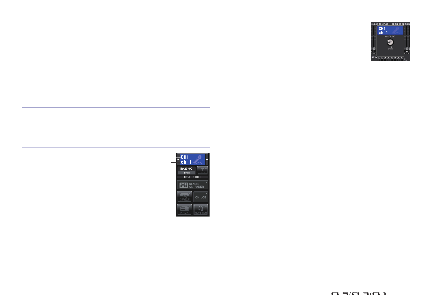
3 DOWN MIX
This field enables you to view the downmix
coefficient and L/R button settings.
Press this field to open the TO STEREO/MONO
window.
INPUT DELAY field
This field enables you to view the delay settings.
1 ON indicator
Indicates the on/off status of the delay.
2 Delay time
The delay value is displayed by milliseconds (ms) and also by currently-selected scale. If
the scale uses units of ms, the value in the bottom row will not be displayed. Only the
ms value appears in the middle row.
Press this field to open the INPUT DELAY 8ch window.
HPF field (input channels only)
This field enables you to set the HPF. If an output channel
is selected, a gray circle will appear in location
will not be displayed.
1, and 2
1
1 HPF knob
Sets the HPF cutoff frequency.
2 ON button
Switches the HPF on or off.
2
EQ parameter field
This field displays the 4-band EQ parameter settings. Press each
knob to open the HPF/EQ 1ch window.
1 Q knob
Specifies the Q for each band.
If the HIGH band filter type is set to LPF or H.SHELF (high-
shelving), or the LOW band filter type is set to L.SHELF (lowshelving), the Q knob will not be displayed. Only the filter
type name will be displayed.
NOTE
• Fully rotating the HIGH band Q knob on the panel counterclockwise while pressing and holding it down will set the filter
type to LPF. Fully rotating the Q knob clockwise while pressing
and holding it down will set the filter type to high-shelving.
• Fully rotating the LOW band Q knob on the panel clockwise while
pressing and holding it down will set the filter type to lowshelving.
• If an output channel has been selected, fully rotating the LOW
band Q knob on the panel counter-clockwise while pressing and holding it down will set the filter
type to HPF.
• You can also switch the filter type in the HPF/EQ 1ch window.
2 FREQUENCY knob
Sets the center frequency (or cutoff frequency) for each band.
3 GAIN knob
Sets the amount of cut/boost for each band.
NOTE
• If the HIGH band filter type is set to LPF, you can switch LPF on or off using the HIGH band GAIN
knob on the panel.
• If the LOW band filter type is set to HPF, you can switch HPF on or off using the LOW band GAIN
knob on the panel.
9
Reference Manual
Page 10
SELECTED CHANNEL section
1 2
3
4
1
2
43
21
2
1
3
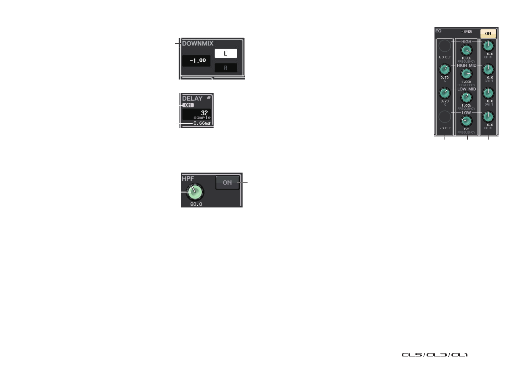
EQ graph field
This field graphically indicates the approximate response of the EQ. Press this field to open
the HPF/EQ 1ch window, in which you can set the attenuator, HPF, and EQ.
DYNAMICS1/DYNAMICS2 field
This field enables you to set the Dynamics 1/2 parameters.
1 OVER indicator
Warns you when the signal is clipping.
2 Level meter
Displays the output signal level (green) and the amount of gain reduction (orange)
when the Dynamics is on. The current threshold setting is shown as a white vertical line.
3 Threshold
Specifies the threshold.
4 Parameters
Indicate the values of parameters that vary depending on the currently-selected
dynamics type.
Press this field to open the DYNAMICS 1/DYNAMICS 2 1ch window, in which you can
make detailed parameter settings.
INSERT field
This field enables you to make insert settings.
1 Popup button
Press this button to open the INSERT/DIRECT OUT
1ch window.
2 ON button
Switches the insert on or off.
3 RACK EDIT button
Appears if an effect or Premium Rack is inserted. Press this button to display the edit
screen for the inserted rack.
4 IN indicator
Appears if a port has been assigned to the insert-in patch. It lights when the signal is
sent to the insert-in.
DIRECT OUT field
This field enables you to make Direct Out settings.
1 Popup button
Press this button to open the INSERT/DIRECT OUT 1ch
window. The Direct Out level value will appear below the
button.
2 ON button
Switches the Direct Out on or off.
RECALL SAFE field
This field enables you to make Recall Safe settings.
1 Popup button
Press this button to open the RECALL SAFE window.
2 ON button
Switches the Recall Safe status on or off.
3 PA RTI A L ind icat or
Lights only if some of the channel parameters are set to Recall Safe.
10
Reference Manual
Page 11

SELECTED CHANNEL section
1
2
3
1
3
2
4
5
6
FADER field
This field enables you to make settings for the channel on/off
status and the level.
1 Fader
Displays the current level.
Use the faders on the top panel to set the levels.
2 Level indicator
Displays the current level setting by numerical value. If
the signal is clipping at any point in the channel, the Σ CLIP indicator will light.
3 ON button
Switches the channel on and off. The button is linked with the corresponding [ON] key
on the top panel.
NOTE
For CL V2.0 and later, the TOUCH AND TURN function assigned to one of the USER DEFINED
knobs enables you to control the fader in the FADER field of the SELECTED CHANNEL VIEW
screen.
DCA/MUTE field
This field enables you to select the DCA or mute group to which the
channel is assigned.
1 Ta bs
Select a DCA or mute group. Press the selected tab once again
to open the DCA/MUTE GROUP ASSIGN MODE window.
When the mute group tab is selected:
4 Mute group select buttons
Select the mute group to which the channel is assigned.
NOTE
If the dimmer level is set to the mute group, this button lights
orange.
5 SAFE button
Temporarily removes the channel from the mute group.
6 DCA group indicators
Indicate the DCA group to which the channel is assigned.
When the DCA group tab is selected:
2 DCA group select buttons
Select the DCA group to which the channel is assigned.
3 Mute group indicators
Indicate the mute group to which the channel is assigned.
11
Reference Manual
Page 12
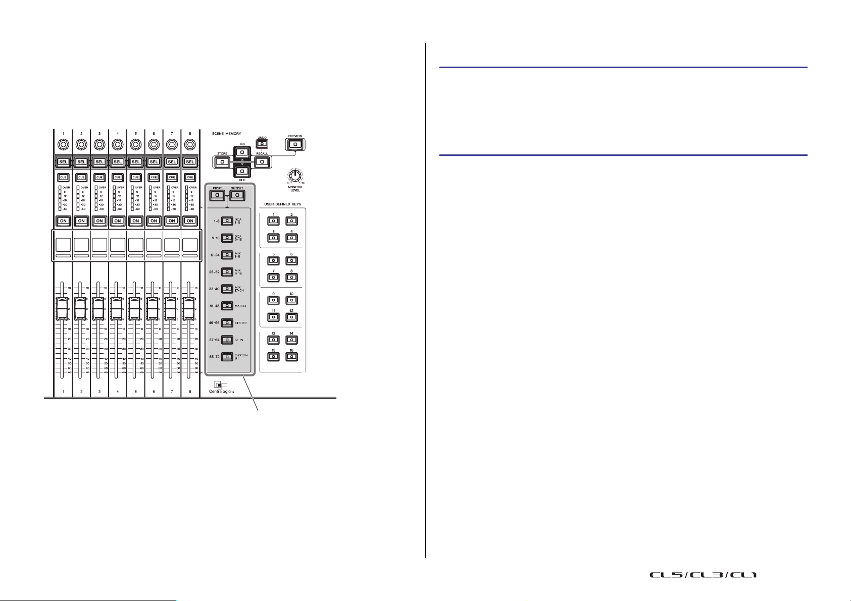
Centralogic section
Bank Select keys
Centralogic section
The Centralogic section located below the touch screen lets you recall and simultaneously
control a set of eight input channels, output channels, or DCA groups. If you press one of the
Bank Select keys, the channels or DCA groups corresponding to that key will be assigned to
the Centralogic section, and can be controlled using the faders, [ON] keys, and [CUE] keys in
the Centralogic section.
Operations in the Centralogic section
STEP
1. Use the Bank Select keys in the Centralogic section to select the channels or DCA
groups that you want to control.
2. Use the faders and [ON] keys of the Centralogic section to adjust the level of the (up
to) eight selected channels and switch them on/off.
3. Use the fields on the OVERVIEW screen and the multifunction knobs to adjust the
parameters for the group of up to eight channels.
NOTE
• When the SELECTED CHANNEL VIEW screen is displayed, you can switch to the OVERVIEW
screen by pressing any of the multifunction knobs 1-8. This is convenient when you want to
quickly switch to the OVERVIEW screen while leaving the same channels or DCA groups
selected for control.
• The bottom line of the OVERVIEW screen shows the channels or DCA groups that can be
controlled by the faders, [ON] keys and [CUE] keys of the Centralogic section.
• The top line of the OVERVIEW screen shows the channels that can be controlled by multifunction
knobs 1 - 8 in the Centralogic section.
12
Reference Manual
Page 13
Centralogic section
: Selected channel
: Unselected channel
1
4
3
2
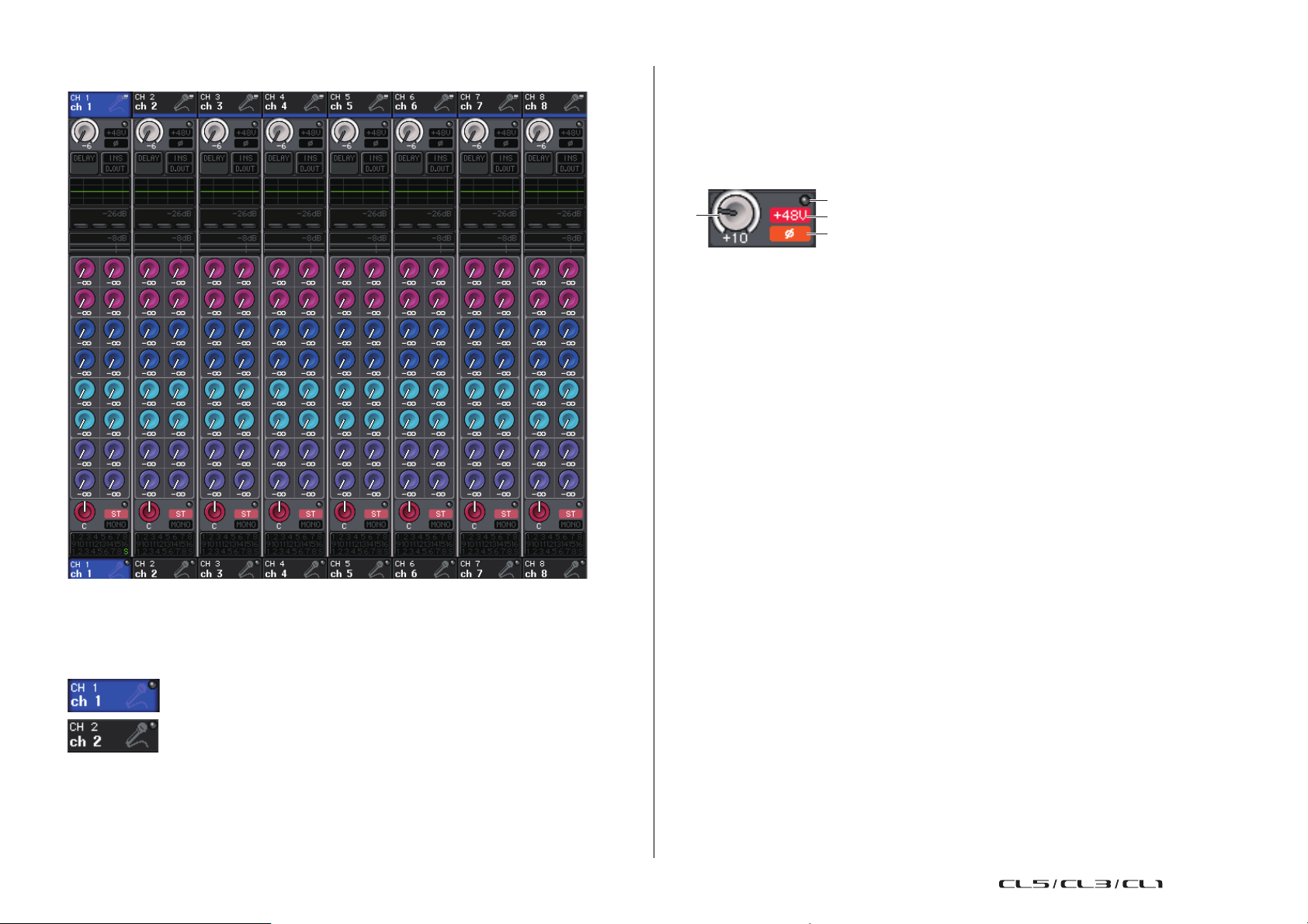
OVERVIEW Screen
GAIN/PATCH field
This field enables you to make HA (head amp) analog or digital gain settings. You can also
view the operational status of the head amp.
The view and the function of the controllers in this field vary depending on the type of the
selected channel.
If the head amp is patched:
1 GAIN knob
Sets the analog gain of the head amp.
• Press this field to assign the GAIN knob to the corresponding multifunction knob in the
Centralogic section, which enables you to adjust the gain. If the Gain Compensation
function is turned on, an indicator appears, showing the level of the signal output to
the audio network.
• If the GAIN knob has been assigned to a multifunction knob, press the knob to open
the GAIN/PATCH 8ch window.
2 OVER indicator
Lights when a signal at the input port or from the rack output exceeds the full scale level.
This indicator is available only if an input channel is selected.
3 +48V indicator
Indicates the phantom power (+48V) on or off status for the head amp. This indicator is
not displayed unless the head amp is patched to the channel.
CHANNEL NAME field
This field appears at the top and bottom of the screen and displays the channel number,
name, and icon for the currently-selected eight channels. The name of the currently-selected
channel is highlighted.
NOTE
If you have retained a specific channel (that is controlled by the faders or knobs in the Centralogic
section) by pressing and holding down the corresponding Bank Select key, the channel name
display at the top of the channel strip graphic may differ from the name displayed at the bottom
of the same channel strip.
13
4 Ø (Phase) indicator (input channels only)
Indicates the input phase setting for the head amp
NOTE
• If the slot is not connected to the head amp, the patch and the type of the MY card will be
displayed.
• If GAIN KNOB FUNCTION is set to DIGITAL GAIN in the PREFERENCE screen, the DIGITAL
GAIN knob will appear instead of knob
• Press the SETUP button, then the USER SETUP button, select the PREFERENCE tab, and then
set the GAIN KNOB FUNCTION to DIGITAL GAIN. You will be able to adjust the digital gain value
by using the [TOUCH AND TURN] knob.
• You can also operate the digital gain by assigning INPUT GAIN DIGITAL GAIN to a USER
DEFINED knob, or by assigning an ALTERNATE function to a USER DEFINED key and then
adjusting the USER DEFINED knob or the GAIN knob for the selected channel while
ALTERNATE is on.
1, and indicator 3 will not be displayed.
Reference Manual
Page 14

INPUT DELAY field (input channels only)
If the slot is patched:
The slot name will appear.
If the rack is connected:
The patch and module name will appear.
If the output is connected:
Only the patch will appear.
1
1
2
This field displays the delay status for the input channel. Press this field to open the INPUT
DELAY 8ch window.
1 DELAY ON/OFF indicator
Indicates the on/off status of the delay.
INSERT/DIRECT OUT field
This field displays the Insert/Direct out status. Press this field to open the INSERT/DIRECT
OUT 8ch window.
Centralogic section
DYNAMICS 1/2 field
This field displays the threshold value and meter for Dynamics
1/2. Press this field to open the DYNAMICS 1/2 1ch window.
NOTE
If DCA or monitor has been selected, this field will be blank.
SEND field
This field displays the send level, send on/off status, and pre/post
settings for 16 buses.
To select the 16 destination buses, use the [MIX 1-16] key/[MIX 17-24/
MATRIX] key in the SELECTED CHANNEL section.
To adjust the send level for each bus, use the SEND knob of the
SELECTED CHANNEL section
This field varies depending on the type of the destination bus.
If the destination bus is VARI (mono):
The knob color and scale color indicate the send on/off and pre/post
status. If the send is off, the knob color turns gray. With the post setting,
the knob scale color turns black.
1 INSERT ON/OFF indicator
Indicates the insert on/off status.
2 DIRECT OUT ON/OFF indicator (input channels only)
Indicates the Direct Out on/off status.
EQ field
This field graphically indicates the approximate response of
the EQ. Press this field to open the HPF/EQ 1ch window, in
which you can set the HPF and EQ.
NOTE
If DCA or monitor has been selected, this field will be blank.
If the destination bus is VARI (stereo):
If a pair of buses (odd-numbered and even-numbered) are in stereo, the
left-hand knob will function as the PAN knob, and the right-hand knob will
function as the SEND knob.
14
Reference Manual
Page 15

Centralogic section
If the destination bus is set to FIXED:
The SEND ON/OFF button for each bus is shown instead of the knob.
TO STEREO/MONO field
This field displays the on/off status and pan/balance setting of the signal sent to the STEREO/
MONO bus.
This field varies depending on the type of the selected channel.
When an input channel or MIX channel is selected:
1
2
1 TO STEREO PAN knob
Sets the pan position of a signal routed to the STEREO bus.
Press the knob to open the STEREO/MONO 8ch window. If the ST IN channel is selected,
you can specify whether to view the PAN knob or the BALANCE knob in this window.
For a MIX channel, the PAN knob will appear if the signal is mono, and the BALANCE
knob will appear if the signal is stereo.
DCA group field
A DCA group (1-16) to which the channel is assigned is displayed on the first or second row
in this field.
Press this field to open the DCA/MUTE GROUP ASSIGN MODE window.
Mute group field
A mute group (1-8) to which the channel is assigned is displayed on the third row in this field.
If the channel has been temporarily removed from the mute group, S (Safe) will appear on the
third row. If a dimmer level has been specified for a mute group, the color of the characters will
change from red to orange.
Press this field to open the DCA/MUTE GROUP ASSIGN MODE window.
2 ST/MONO indicator
Indicates the status of a signal sent to the STEREO/MONO bus.
If an input or MIX channel is set to LCR mode, the LCR indicator
will be displayed.
When a MATRIX channel (monaural) or MONO channel is selected:
The Σ CLIP indicator will light if the signal is clipping at some point in the channel.
For a stereo MATRIX channel or STEREO channel, the BALANCE knob appears, indicating
the balance of the left/right channels.
2
15
Reference Manual
Page 16
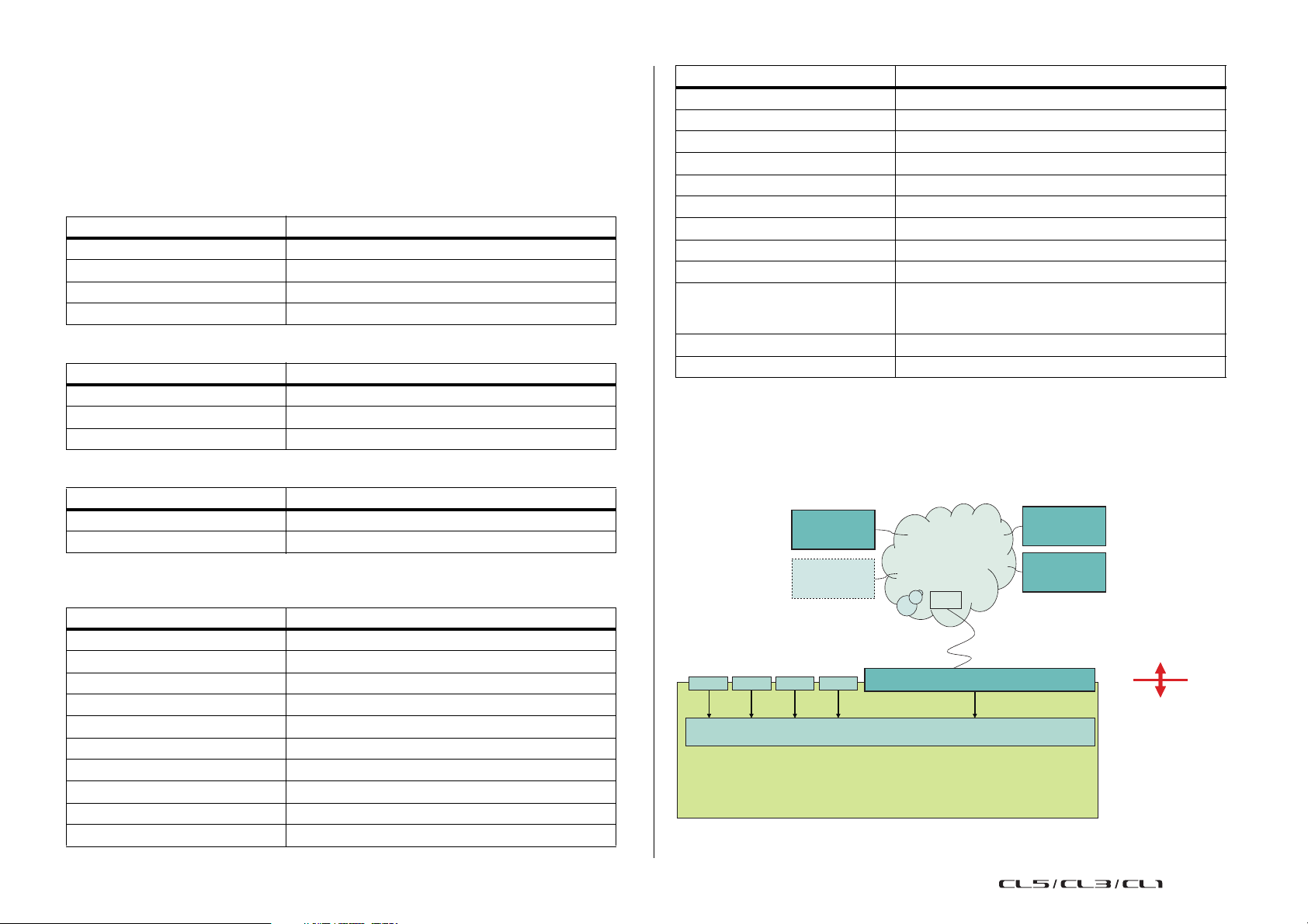
Input and output patching
CL series
I/O Device
Up to 512 channels
(logical value)
Dante
patching
CL series
internal
patching
I/O Device
I/O Device
Input and output patching
This chapter explains how to edit the input patching and output patching, how to connect
inserts, and how to use direct outputs.
When the CL series is in the initial state, the following input ports (jacks/ports) are patched to
each input channel.
For CL5
Input channels Input port (jack/port)
CH1-48 DANTE1-48
CH49-64 DANTE49-64
CH65-72 OMNI1-8
ST IN 1L-8R FX 1L(A)-FX 8R(B)
For CL3
Input channels Input port (jack/port)
CH1-48 DANTE1-48
CH49-64 DANTE49-64
ST IN 1L-8R FX 1L(A)-FX 8R(B)
For CL1
Input channels Input port (jack/port)
CH1-48 DANTE1-48
ST IN 1L-8R FX 1L(A)-FX 8R(B)
When the CL is in the initial state, the output ports (jacks/ports) are patched to the following
output channels.
Output port (jack/port) Output channels
DANTE1-24 MIX 1-24
DANTE25-32 MATRIX1-8
DANTE33-34 STEREO L/R
DANTE35 MONO
DANTE36-37 MONITOR L/R
DANTE38 MONITOR C
DANTE39-40 CUE L/R
DANTE41-64 NO ASSIGN
SLOT1 (1)-(16) MIX1-16
SLOT2 (1)-(8) MIX17-24
Output port (jack/port) Output channels
SLOT2 (9)-(16) MATRIX1-8
SLOT3 (1)-(2) STEREO L/R
SLOT3(3) MONO
SLOT3 (4)-(5) MONITOR L/R
SLOT3(6) MONITOR C
SLOT3 (7)-(8) CUE L/R
SLOT3 (9)-(16) NO ASSIGN
OMNI OUT 1 - OMNI OUT 6 MIX 1-6
OMNI OUT 7 - OMNI OUT 8 STEREO L/R
FX1L(A), FX2L(A), FX3L(A),
FX4L(A), FX5L(A), FX6L(A),
FX7L(A), FX8L(A)
DIGITAL OUT L/R STEREO L/R
RECORDER INPUT L/R STEREO L/R
MIX17, MIX18, MIX19, MIX20, MIX21, MIX22, MIX23,
MIX24
CL console internal patching and Dante audio network patching
The following diagram shows the signal flow through the CL series console, I/O devices, and
Dante audio network.
ID #3
Dante-MY16-AUD
OMNI MY MY MY
8 16 16 16 64
INPUT PATCH
Dante Network
SW
“Dante” (ports)
64/512
ID #1
ID #2
16
Reference Manual
Page 17
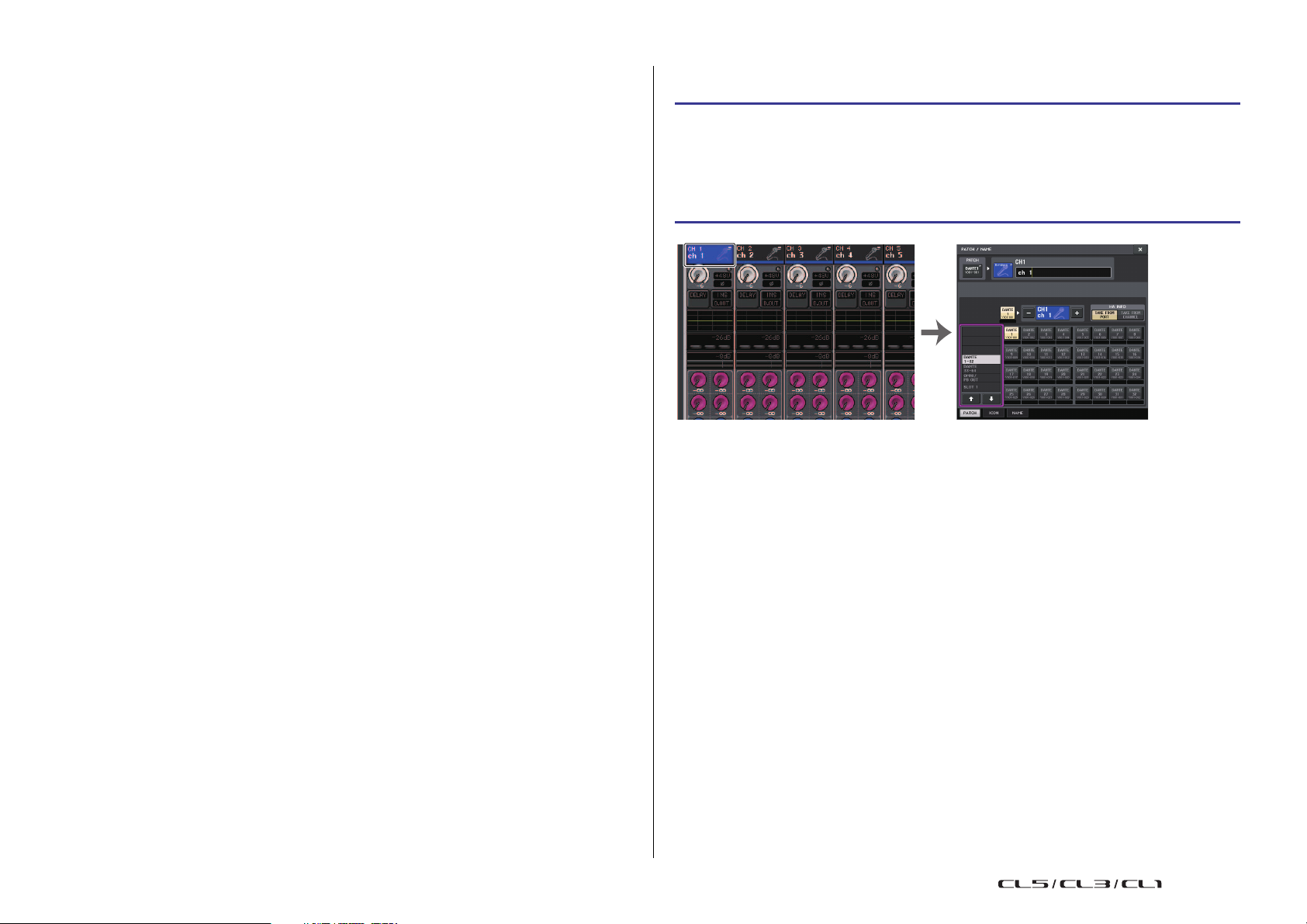
Input and output patching
OVERVIEW screen PATCH/NAME screen
Input patching
CL series consoles and I/O devices feature two types of patching: Dante audio network
patching and CL console internal patching.
For Dante audio network patching, you will use the DANTE INPUT PATCH window. In this
window, you can patch the CL console and I/O device inputs. Sixty-four (64) channels can be
input from a Dante audio network to a CL series console. You can choose up to 64 channels
from a maximum of 512 channels (logical value) of Dante audio network signals. Select the I/
O device (up to 64 channels) that you want to control from the CL series console.
Then, route the input signals (that were patched in the DANTE INPUT PATCH screen) to
channels on the CL series console. To do this, choose input ports from DANTE 1-64 in the
GAIN/PAT C H s c reen.
NOTE
By default, DANTE 1-64 are assigned to input channels 1-64.
Output patching
Use the OUTPUT PORT screen to patch the CL console's output channels and Dante audio
network. In this window, assign output channel signals to DANTE 1-64 ports.
NOTE
By default, MIX 1 - 24 are assigned to DANTE 1 - 24, MATRIX 1 - 8 are assigned to DANTE 25
- 32, STEREO L/R are assigned to DANTE 33/34, and MONO is assigned to DANTE 35.
Next, patch the output signals from DANTE 1-64 (assigned in the OUTPUT PORT SETUP
screen) to I/O rack outputs. Use the OUTPUT PATCH screen of the I/O RACK to make these
assignments.
Changing the input patching
STEP
1.
Use the Bank Select keys in the Centralogic section to select the input channels that
you want to control.
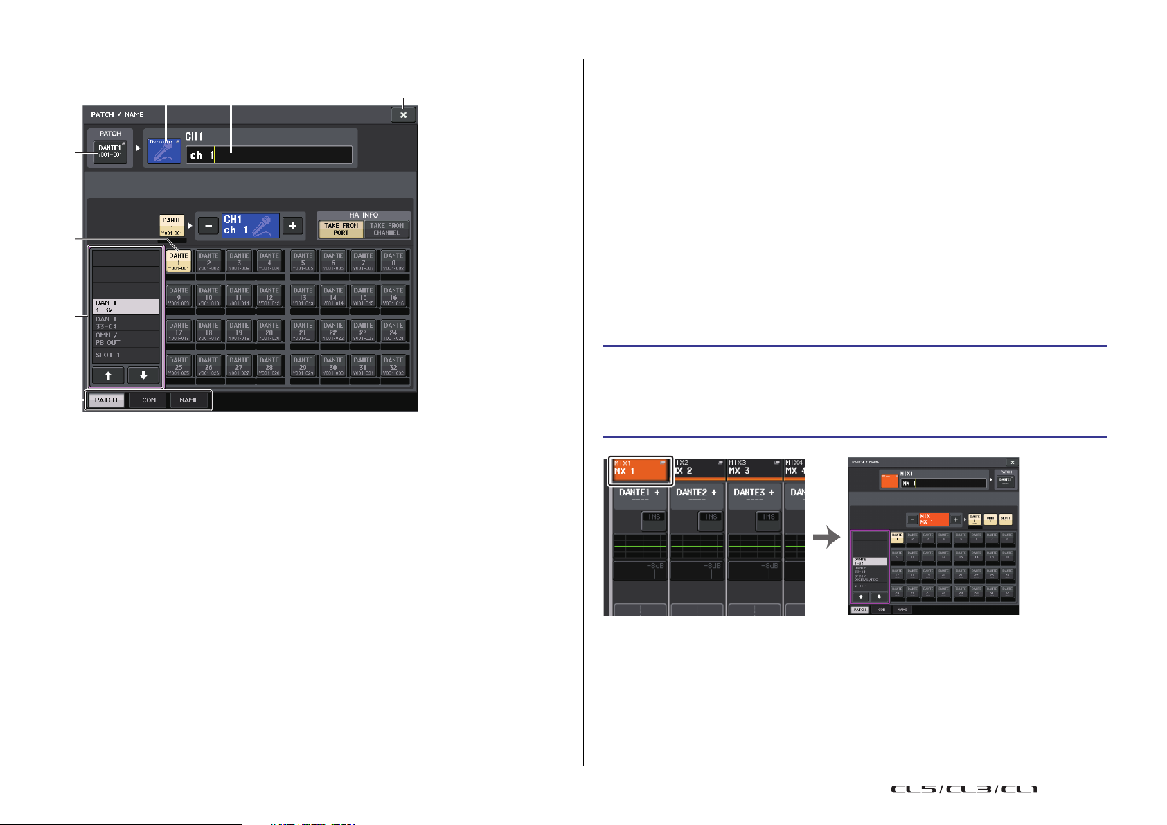
2. Press the channel number/channel name field on the OVERVIEW screen.
3. Select the type of port in the category select list on the PATCH/NAME screen, and
use the port select buttons to select the input port.
NOTE
You can also select an input port from the GAIN/PATCH screen.
17
Reference Manual
Page 18
Input and output patching
2 73
1
6
4
5
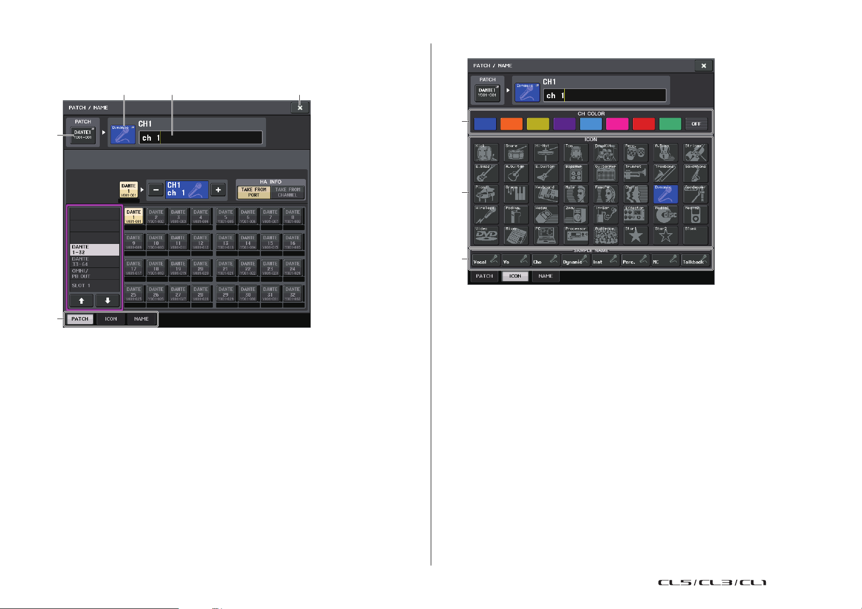
OVERVIEW screen PATCH/NAME screen
PATCH/NAME screen
1 PATCH button
Indicates the currently-selected input port. If you press this button when selecting an
icon or changing the channel name, you will return to the input port select screen.
• PREMIUM RACK... PR1L(A) - PR2R(B)
5 Port select buttons
Select the input port that is assigned to the currently-selected channel.
6 Ta bs
Enable you to switch between items.
7 Close button
Closes the screen.
Changing the output patching
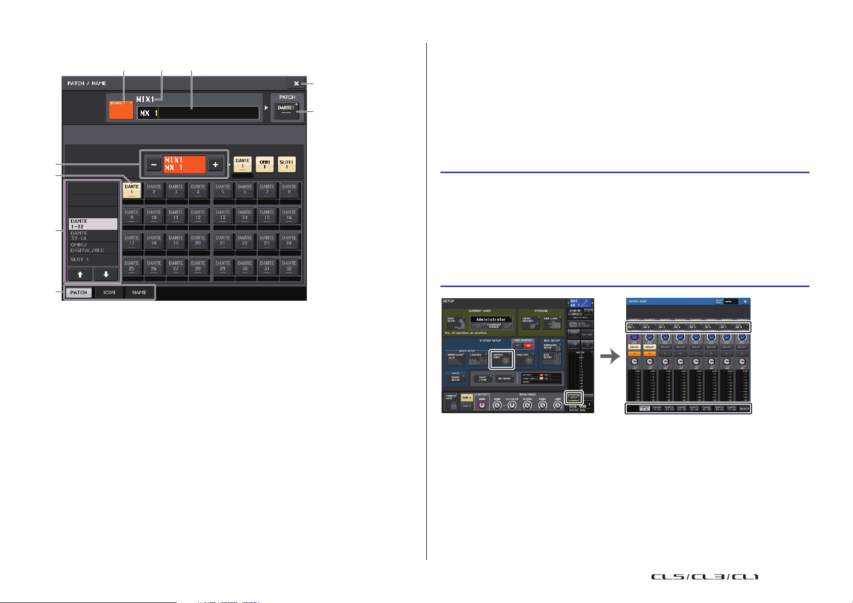
To change the patching, you can either select the output port that will be the output destination
of each output channel, or you can select the output channel that will be the output source for
each output port.
Selecting the output port for each output channel
STEP
1. Use the Bank Select keys in the Centralogic section to select the output channels.
2. Press the channel number/channel name field on the OVERVIEW screen.
3. Select the type of port in the category select list on the PATCH/NAME screen, and
use the port select buttons to select the output port.
2 Icon button
Indicates the icon that is selected for the corresponding channel. When you press this
button, a screen will appear in which you can select an icon or sample name.
3 Channel name input box
Indicates the name that is assigned to the corresponding channel. When you press this
field, a keyboard window allowing you to change the channel name will appear.
4 Category select list
Selects the category of input port. The categories correspond to the following input
ports. The displayed categories vary depending on the channel type.
• DANTE1-32............DANTE1 - DANTE32
• DANTE33-64..........DANTE33 - DANTE64
• OMNI/PB OUT .......OMNI 1 - OMNI 8, PB OUT (L), PB OUT (R)
• SLOT1....................SLOT1(1) - SLOT1(16)
• SLOT2....................SLOT2(1) - SLOT2(16)
• SLOT3....................SLOT3(1) - SLOT3(16)
• EFFECT RACK......FX1L(A) - FX8R(B)
18
Reference Manual
Page 19
Input and output patching
3 54
1
9
6
7
2
8
SETUP screen OUTPUT PORT screen
PATCH/NAME screen
1 PATCH button
Indicates the port that is patched to the output channel. If you press this button when
another tab is active, a window will appear, enabling you to select the network and port.
7 Port select buttons
From the category, these buttons let you select the port to patch. To cancel the
selection, press the button once again.
8 Ta bs
Enable you to switch between items.
9 Close button
Closes the screen.
Selecting the output channel for each output port
STEP
1. In the Function Access Area, press the SETUP button.
2. Press the OUTPUT PORT button in the SYSTEM SETUP field located in the center of
the SETUP screen.
3. In the tabs below the OUTPUT PORT screen, select the output port you want to
control.
4. Press the channel select button of the port you want to operate.
5. Use the category select list and the channel select buttons to select the send-source
channel.
2 Channel select button
Selects the channel to set.
NOTE
Switching channels on this screen will not affect the channel selection on the console.
3 Channel icon button
Indicates the icon and color that are currently selected for the corresponding channel.
When you press this button, a screen will appear in which you can select an icon or
sample name.
4 Channel number display box
Indicates the channel number. This item cannot be changed.
5 Channel name input box
Indicates the name that is assigned to the corresponding channel. When you press this
field, a keyboard window allowing you to assign a name will appear.
6 Category select list
Select the type of port.
19
NOTE
If PATCH CONFIRMATION in the PREFERNCE tab on the USER SETUP screen is ON, a
confirmation dialog box will appear when you attempt to change the patch settings. If STEAL
PATCH CONFIRMATION is ON, a confirmation dialog box will appear when you attempt to
change a location that is already patched elsewhere.
Reference Manual
Page 20
Input and output patching
1
2
3
OVERVIEW screen INSERT/DIRECT OUT Screen (8ch)
CH SELECT screen
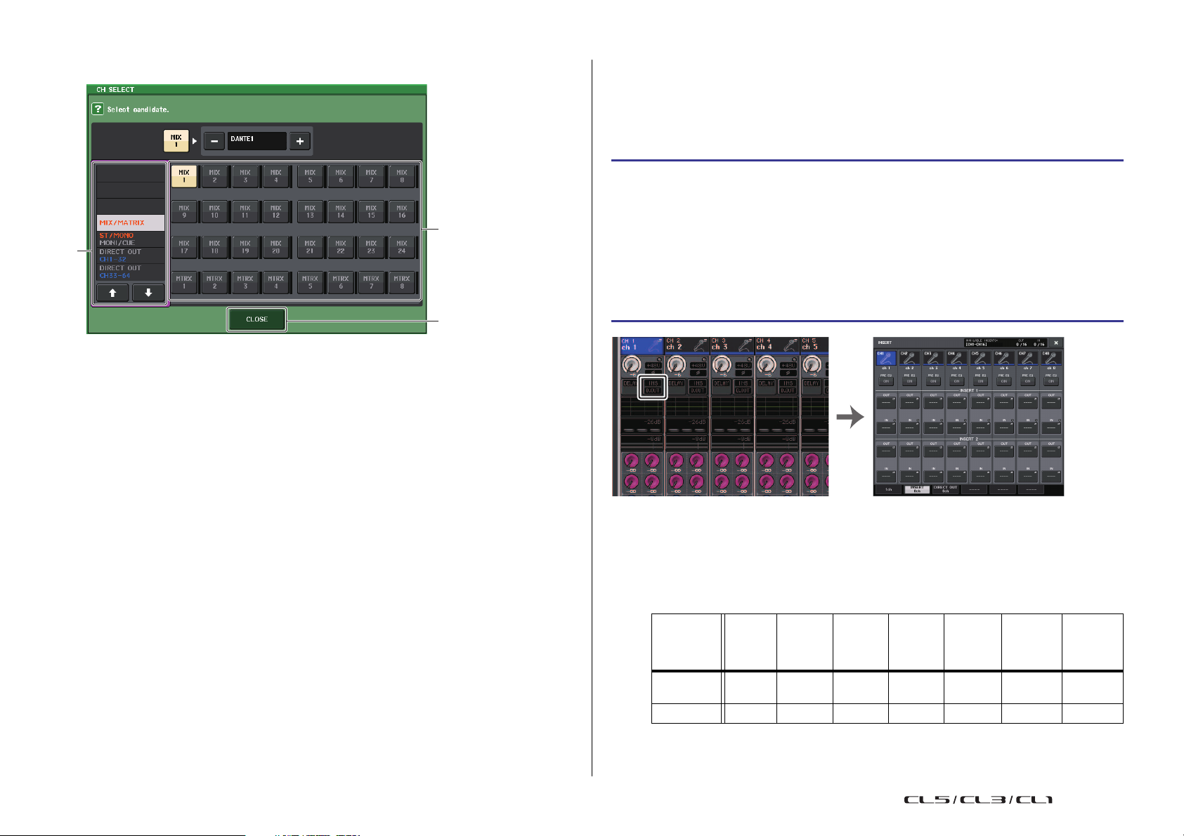
1 Category select list
Select the category of the channel. The categories correspond to the following channels.
They vary depending on the output port type.
• MIX/MATRIX ..........................MIX 1 - MIX 24, MATRIX 1 - MATRIX 8
• ST/MONO/MONI/CUE ........... STEREO L, STEREO R, MONO (C), MONI L, MONI R,
MONI C, CUE L, CUE R, SMON L, SMON R, SMON C,
SMON LFE, SMON Ls, SMON Rs, MMTX L, MMTX R,
MMTX C, MMTX LFE, MMTX Ls, MMTX Rs
• DIRECT OUT 1-32 ................. CH 1 - CH 32 Direct Outs
• DIRECT OUT 33-64 ............... CH 33 - CH 64 Direct Outs
• DIRECT OUT 65-72 ............... CH 65 - CH 72 Direct Outs
• INSERT OUT 1-32 ................. CH 1 - CH 32 Insert Outs
• INSERT OUT 33-64 ............... CH 33 - CH 64 Insert Outs
• INSERT OUT 65-72 ............... CH 65 - CH 72 Insert Outs
• INSERT OUT MIX/MATRIX.... MIX 1 - MIX 24, MATRIX 1 - MATRIX 8 Insert Outs
• INSERT OUT ST/MONO........ STEREO L, STEREO R, MONO (C) Insert Outs
• CASCADE MIX/MATRIX........ MIX 1 - MIX 24, MATRIX 1 - MATRIX 8
• CASCADE ST/MONO/CUE ... STEREO L, STEREO R, MONO (C), CUE L, CUE R
NOTE
In the case of the CL3/CL1, channels that do not exist on those models will not be shown.
2 Channel select button
Select the channel to be assigned to the output port from the current category.
3 CLOSE button
Closes the screen.
Inserting an external device into a channel
You can insert an effect processor or other external device into the signal path of an INPUT,
MIX, MATRIX, STEREO, or MONO channel. When doing so, the type of input/output port
used for the insertion and the location of the insertion in/out can be specified individually for
each channel.
STEP
1. Connect your external equipment to an OMNI IN/OUT jack or to an I/O card
installed in slots 1 - 3.
2. Use the Bank Select keys in the Centralogic section to select the channel to which
you want to assign the input source.
3. Press the INSERT/DIRECT OUT field.
4. Press the INSERT OUT or INSERT IN button.
5. Select an output port or an input port.
6. Press the INSERT ON button.
NOTE
• If you install a digital I/O card in a slot and digitally connect an external device, you must
synchronize the word clock of the CL console and the external device (page 218).
• There is a limit to the sum of INSERT 1 and INSERT 2 for each channel group, as shown in the
table below. You can select any output or input ports.
CH49-64
CH1-16 CH17-32 CH33-48
INSERT
OUT
INSERT IN 16 16 16 16 8 30(24)* 8
16 16 16 16 8 30(24)* 8
(CL5 and
CL3
only)
* When using Surround mode
CH65-72
(CL5
only)
MIX1-24/
ST/
MONO
MATRIX
1-8
20
Reference Manual
Page 21
Input and output patching
1
2
3 < < 9
4
5
86 7
• If you exceed the INSERT OUT or INSERT IN limitation, the indicator will light up on the left.
• If the limit is exceeded, invalid ports will be marked with a strike-out line.
• If the limit is exceeded, the following ports will take priority per channel group (listed in the table
above).
1 INSERT 1 will take priority over INSERT 2.
2 Lower-number channel will take priority.
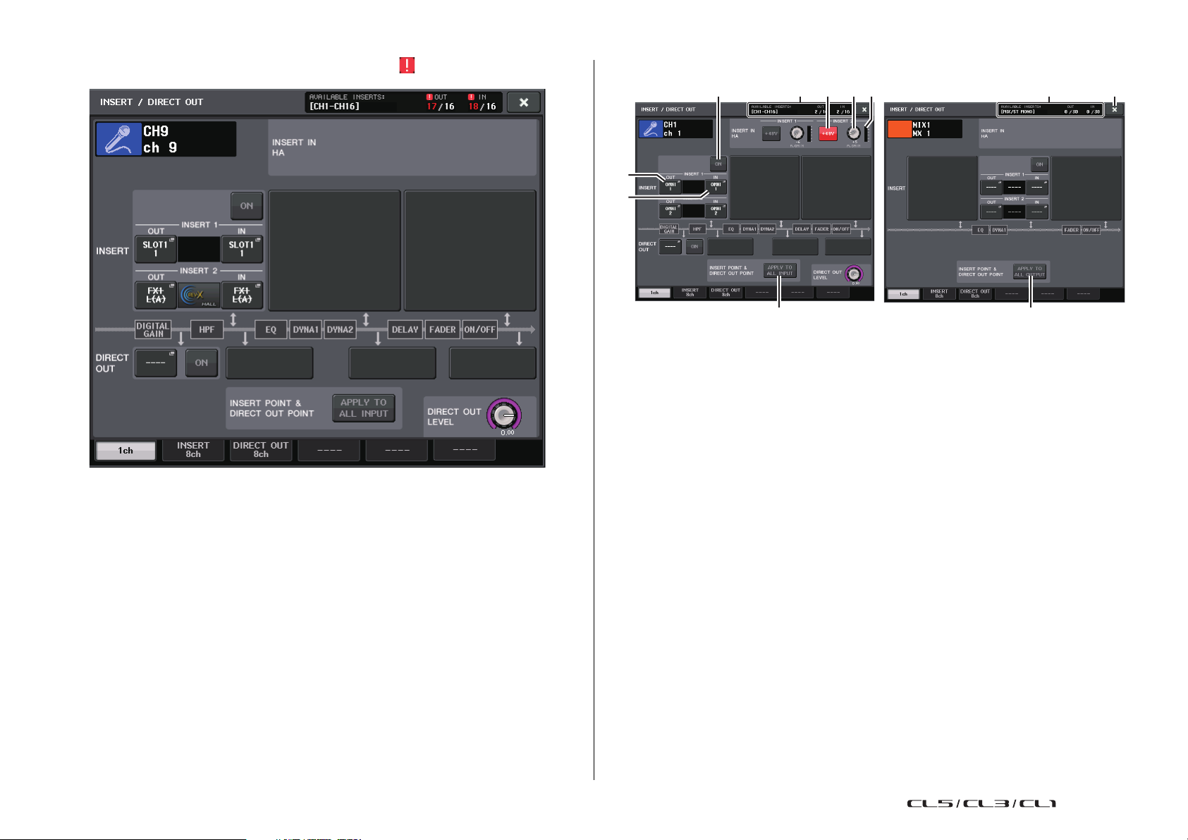
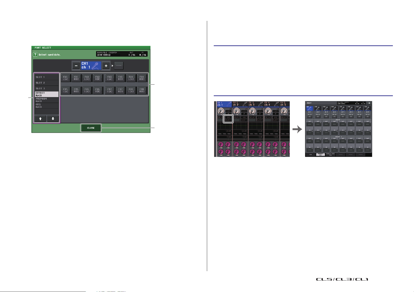
INSERT/DIRECT OUT screen (1ch)
INSERT field
This field enables you to make insert settings. Press one of three fields to choose PRE EQ
(immediately before the EQ), PRE FADER (immediately before the fader), or POST ON
(immediately after the [ON] key) as the insert position.
NOTE
You can set the I/O ports to function as an insert for each block.
1 INSERT OUT button
Displays the currently-selected output port for insert 1 and insert 2. Press this button to
open the PORT SELECT window, in which you can select an output port.
2 INSERT IN button
Displays the currently-selected input port for insert 1 and insert 2. Press this button to
open the PORT SELECT window, in which you can select an input port.
21
3 INSERT ON/OFF button
Switches the insert on or off.
4 APPLY TO ALL INPUT button (input channels only)
Specifies whether the insert position and direct out point setting will be applied to all
input channels.
5 APPLY TO ALL OUTPUT button (output channels only)
Specifies whether the insert point setting will be applied to all output channels.
NOTE
Insert 1 and insert 2 are serial connections with fixed sequential numbers.
Reference Manual
Page 22

Input and output patching
1
4
3
2
INSERT IN HA field
This field will appear if you have selected an input port (that features a head amp) as the
insert-in.
6 +48V button
Switches head amp phantom power (+48V) (currently-selected for insert 1 and insert 2)
on or off.
7 A.GAIN knob
Indicates the currently-selected head amp analog gain setting for insert 1 and insert 2.
Press these knobs to control the parameter values using the multifunction knobs.
NOTE
• If you have selected the OMNI IN jack on the CL console
as the input port for insert-in, make the HA settings in the
INSERT IN HA field.
• Even if the INSERT ON/OFF button is OFF, the signal
selected for insert-out will continue to be sent.
8 HA meter
Displays the level of the currently-selected head amp input signal for insert 1 and insert
2.
9 Close button
Closes the screen.
0 Resource Meter
Displays the settings for each channel for INSERT IN and INSERT OUT.
NOTE
If surround mode is set on the CL series console, the INSERT resources for output channels
[MIX/ST MONO] are reduced from 30 to 24.
INSERT/DIRECT OUT screen (8ch)
1 Channel select button
Selects the channel to set. The channel icon, color, and number appear.
2 INSERT ON/OFF button
Switches the insert on or off. The currently-specified insert point setting appears above
the button.
3 INSERT OUT button
Indicates the currently-selected port. Press this button to open the PORT SELECT screen,
in which you can select an output port.
22
4 INSERT IN button
Indicates the currently-selected port. Press this button to open the PORT SELECT screen,
in which you can select an input port. You can also view the insert-in level by checking
the indicator located to the right of the this button.
Reference Manual
Page 23
Input and output patching
1
2
3
OVERVIEW screen INSERT/DIRECT OUT Screen (8ch)
PORT SELECT screen
Displayed when you press either the INSERT OUT or INSERT IN button in the one-channel
or the eight-channel INSERT/DIRECT OUT window. Set the input/output port used for
insertion.
1 Category select list
Selects the category of port. The categories correspond to the following ports. The
displayed categories vary depending on the channel type.
• OMNI...................................... OMNI1 - OMNI8
• SLOT1....................................SLOT1(1) - SLOT1(16)
• SLOT2....................................SLOT2(1) - SLOT2(16)
• SLOT3....................................SLOT3(1) - SLOT3(16)
• GEQ RACK............................ GEQ1L(A) - GEQ16R(B)
(MIX/MATRIX/STEREO/MONO channels only)
GEQ1L(A) - GEQ8R(B) (INPUT channels only)
• EFFECT RACK...................... FX1L(A) - FX8R(B)
• PREMIUM RACK...................PR1L(A) - PR8R(B)
Directly outputting an INPUT channel
The signal of an INPUT channel can be output directly from an OUTPUT jack on the I/O
device, from the desired OMNI OUT jack, or from the output channel of a desired slot.
STEP
1. Connect your external device to an OMNI OUT jack, OUTPUT jack, or to an I/O card
installed in slot 1-3.
2. Use the Bank Select keys in the Centralogic section to select the input channel that
you want to output directly.
3. Press the INSERT/DIRECT OUT field in the OVERVIEW screen.
4. Press the DIRECT OUT PATCH button in the INSERT/DIRECT OUT screen.
5. Select an output port.
NOTE
If you install a digital I/O card in a slot and digitally connect an external device, you must
synchronize the word clock of the CL console and the external device (page 218).
2 Port select buttons
Assign the port that will be used as insert-out/insert-in for the currently-selected
channel.
NOTE
If a rack in which a GEQ, PEQ, or Premium Rack is mounted is specified as the insert-out or
insert-in, the other patch point will automatically be assigned to the same rack. Also, insert mode
will automatically be switched on. Additionally, if you defeat the insert-out or insert-in of a rack in
which a GEQ, PEQ, or Premium Rack is mounted, the other patch point will automatically be
defeated and at the same time insert mode will automatically be switched off.
3 CLOSE button
Closes the screen.
23
Reference Manual
Page 24

Input and output patching
5
4
1
6
32
1
2
3
4
INSERT/DIRECT OUT screen (1ch)
1 DIRECT OUT field
Enables you to make settings for direct output. Press one of four fields to choose PRE HPF
(immediately before the HPF), PRE EQ (immediately before the EQ) or PRE FADER
(immediately before the fader), or POST ON (immediately after the [ON] key) as the direct
output position.
2 DIRECT OUT PATCH button
Displays the currently-selected Direct Out output port. Press this button to open the
PORT SELECT window, in which you can select an output port.
3 DIRECT ON button
Switches the Direct Out on or off.
4 DIRECT OUT LEVEL knob
Indicates the output level of the Direct Out. Press this button to control the level using
the multifunction knob.
INSERT/DIRECT OUT screen (8ch)
1 DIRECT ON button
Switches the Direct Out on or off. The currently-selected Direct Out point is indicated
above the button.
2 DIRECT OUT PATCH button
Displays the currently-selected Direct Out output port. Press this button to open the
PORT SELECT window, in which you can select an output port.
3 DIRECT OUT LEVEL knob
Indicates the output level of the Direct Out. Press this button to control the level using
the multifunction knob.
4 Close button
Closes the screen.
5 APPLY TO ALL INPUT button (input channels only)
Specifies whether the insert point/Direct Out point settings will be applied to all input
channels.
6 Close button
Closes the screen.
24
Reference Manual
Page 25
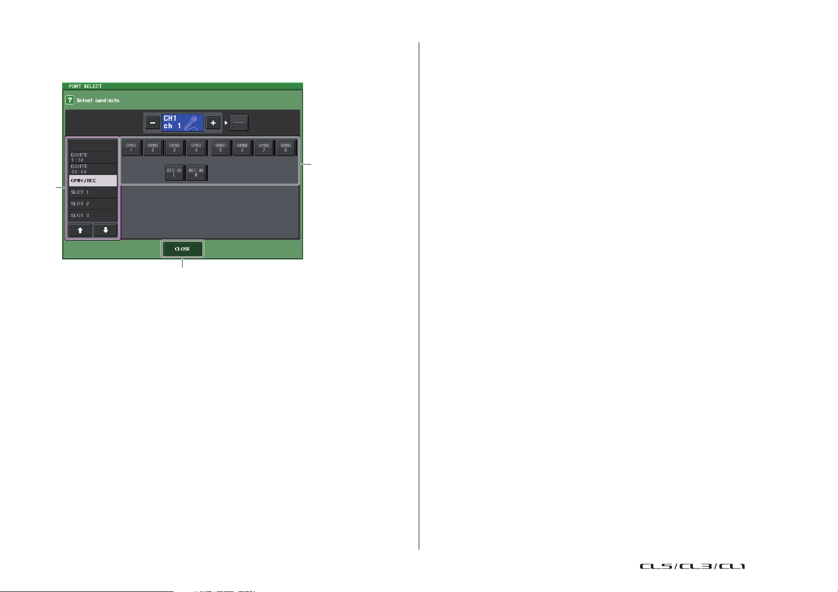
PORT SELECT screen
1
2
3
Displayed when you press the DIRECT OUT PATCH button in the one-channel or the eightchannel INSERT/DIRECT OUT window. Set the output port used for direct output.
1 Category select list
Selects the category of output port. The categories correspond to the following output
ports. The displayed categories vary depending on the channel type.
• OMNI/REC .............OMNI1-OMNI8, REC IN(L), REC IN(R)
• SLOT1....................SLOT1(1) - SLOT1(16)
• SLOT2....................SLOT2(1) - SLOT2(16)
• SLOT3....................SLOT3(1) - SLOT3(16)
• DANTE1-32............DANTE1 - DANTE32
• DANTE33-64..........DANTE33 - DANTE64
Input and output patching
2 Output port select buttons
Assign the output port used for direct output of the currently-selected INPUT channel.
3 CLOSE button
Closes the screen.
25
Reference Manual
Page 26
Input channels
INPUT PATCH
MIX
12 23
...
24
ST
LR
M
O
N
O
(C)
MATRIX
12 7 8
...
CUE
LR
MIX
12 23
24STLR
M
O
N
O
(C)
MATRIX
12 78
CUE
LR
INPUT PATCH
Input channels
This chapter explains various operations for input channels.
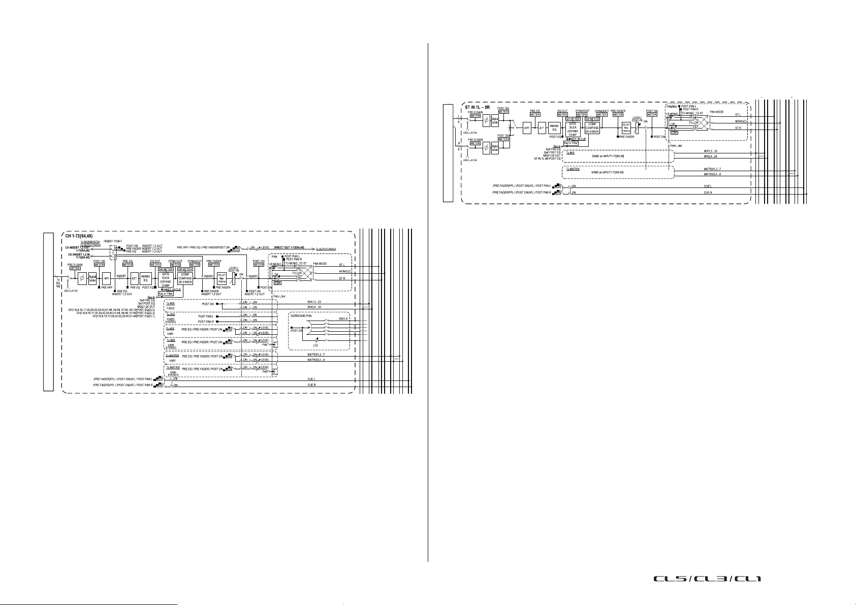
Signal flow for input channels
The input channels comprise the section that processes signals received from the I/O
devices, rear panel input jacks, or slots 1-3, and sends them to the STEREO bus, MONO bus,
MIX buses, or MATRIX buses. There are two types of input channels, as follows.
MONO channels
These channels are used to process monaural signals. When the CL series console is in the
default state, the input signal from the Dante connector is assigned.
STEREO channels
These channels are used to process stereo signals. When the CL series console is in the
default state, the input signal from the EFFECT RACK 1 - 8 is assigned.
•INPUT PATCH
Assigns input signals to the input channels.
• Ø (phase)
Switches the phase of the input signal.
• DIGITAL GAIN
Attenuates/boosts the level of the input signal.
• HPF (High Pass Filter)
Cuts the region below the specified frequency.
• 4 BAND EQ (4 band equalizer)
A parametric EQ with four bands: HIGH, HIGH MID, LOW MID, and LOW.
• DYNAMICS 1
This is a dynamics processor that can be used for gating and ducking, or as an expander
or compressor.
• DYNAMICS 2
This is a dynamics processor that can be used as a compressor, compander, or de-esser.
•INPUT DELAY
Corrects input signal delay. You can specify up to 1000ms.
• LEVEL/DCA 1-16
Adjusts the input level of the effect.
•ON (On/off)
Turns the input channel on or off. If this is off, the corresponding channel will be muted.
26
Reference Manual
Page 27
Input channels
OVERVIEW screen PATCH/NAME screen
•Pan
Adjusts the panning of signals sent from the input channel to the STEREO bus. For the
STEREO channel, you can switch between PAN and BALANCE. The BALANCE parameter
adjusts the volume balance of the left/right signals sent from the STEREO channel to the
STEREO bus. You can turn on PAN LINK in the BUS SETUP window so that the setting of
the PAN parameter will also be applied to signals sent to two MIX or MATRIX buses that
are set to stereo.
• LCR (Left/Center/Right)
Sends the input channel signal to the STEREO bus/MONO bus as a three-channel signal
that consists of the L/R channels plus the center channel.
• MIX ON/OFF (MIX send on/off)
This is an on/off switch for signals sent from the input channel to MIX buses 1 - 24.
• MATRIX LEVEL 1-24 (MATRIX send levels 1-24)
Adjusts the send level of signals sent from the input channel to VARI type MIX buses 1 -
24. As the position from which the signal is sent to the MIX bus, you can choose from
the following: immediately before EQ, pre-fader, or post-fader.
• MATRIX ON/OFF (MATRIX send on/off)
This is an on/off switch for signals sent from the input channel to MATRIX buses 1 - 8.
• MATRIX LEVEL 1 - 8 (MATRIX send levels 1 - 8)
Adjusts the send level of the signal sent from the input channel to MATRIX buses 1 - 8.
As the position from which the signal is sent to the MATRIX bus, you can choose from
the following: immediately before the EQ, pre-fader, or post-fader.
• INSERT (MONO channels only)
You can patch the desired output/input ports to insert an external device such as an
effect processor. For the position of the insert-out/insert-in point, you can choose
immediately before the EQ, immediately before the fader, or immediately after the [ON]
key.
• DIRECT OUT (MONO channels only)
This can be patched to any output port, and the input signal sent directly from that
output port. For the position of the direct output, you can choose immediately before
the HPF, immediately before the EQ, immediately before the fader, or immediately after
the [ON] key.
• METER
Indicates the input channel level. You can switch the position at which the level is
detected (page 120).
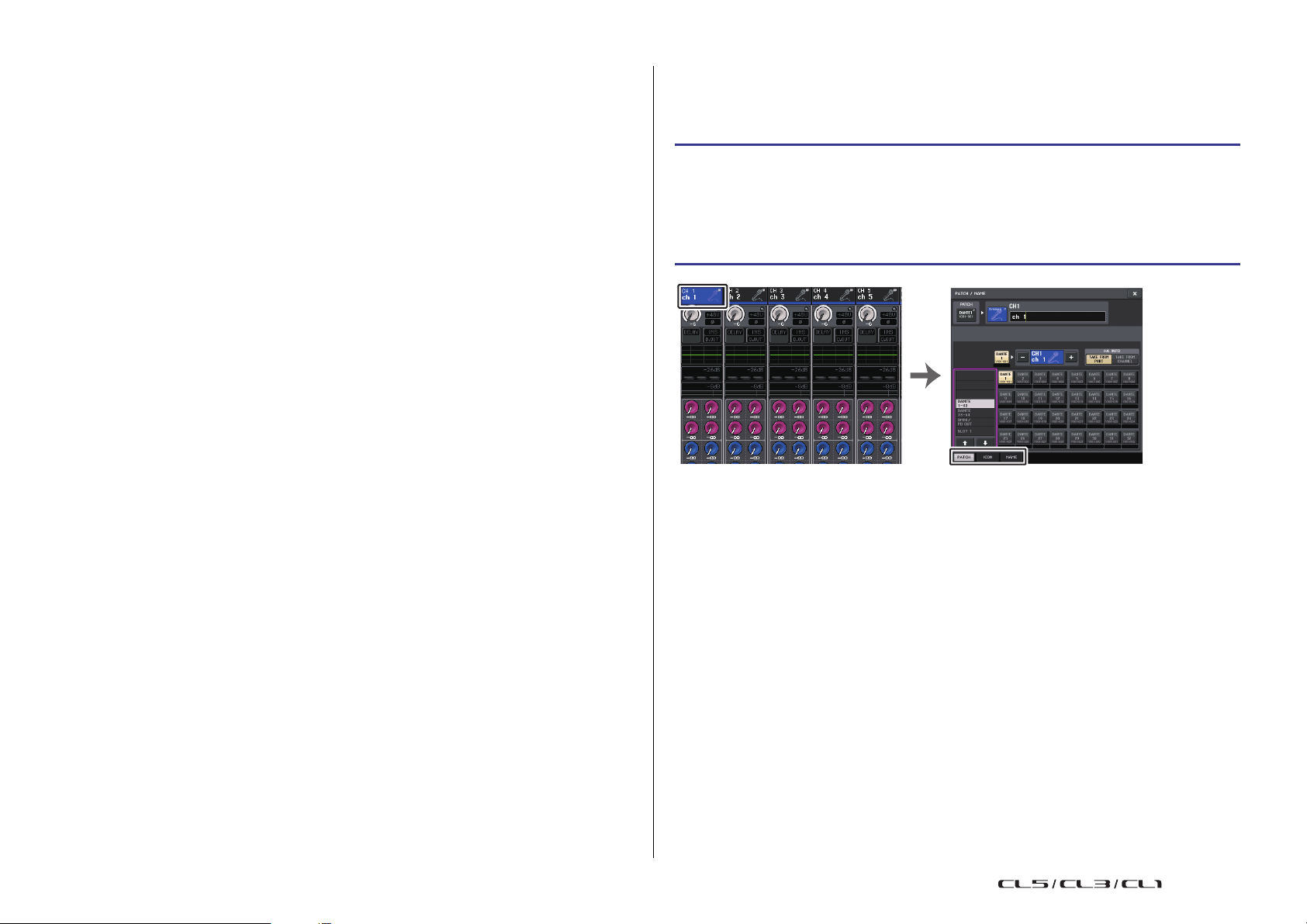
Specifying the channel name/icon
On the CL series unit, you can specify the on-screen name and icon for each input channel.
Here we will explain how to specify the channel name and icon.
STEP
1. Use the Bank Select keys in the Centralogic section to select the input channels.
2. Press the channel number/channel name field of the channel you want to specify on
the OVERVIEW screen.
3. Switch between items in the tabs on the PATCH/NAME screen, and specify a channel
name and icon.
27
Reference Manual
Page 28
Input channels
2 53
1
4
1
2
3
PATCH/NAME screen
When selecting the PATCH tab
1
PATCH button
Indicates the currently-patched port. If you press this button when another tab is active,
a window will appear, enabling you to select the network and port.
2 Icon button
Indicates the icon and color that are currently selected for the corresponding channel.
When you press this button, a screen will appear in which you can select an icon or
sample name.
3 Channel name input box
Indicates the currently-specified channel. When you press the inside of this box, the
SOFT KEYBOARD window will appear, enabling you to edit the channel name.
When selecting the ICON tab
Channel color select buttons
1
Select a channel color.
2 Icon select buttons
Select a channel icon.
3 Sample name setup buttons
Select a preset sample name. You can edit the name on the NAME tab later.
NOTE
• You can also add or edit characters in the channel name field after you have entered the sample
name. If you want to quickly assign channel names that consist of a common name plus a
consecutive number, such as “Vocal 1” or “Vocal 2,” enter a sample name first, and then add a
number.
• In CL V1.7 and later, you can set the channel color to black (OFF). The channel indicators on
channels for which black is selected will go off.
4 Ta bs
Enable you to switch between items.
5 Close button
Closes the screen.
28
Reference Manual
Page 29

When selecting the NAME tab
OVERVIEW screen GAIN/PATCH window (1 ch)
32 4 5 6 7
1 8
You can directly enter a channel name on the keyboard screen.
Input channels
NOTE
• The PAD will be switched on or off internally when the HA gain is adjusted between +17 dB and
+18 dB.
• Keep in mind that noise may be generated if there is a difference between the Hot and Cold
output impedance of the external device connected to the INPUT connector when using phantom
power.
• The GAIN knob, +48V button, and Ø button are valid only on channels for which the assigned
input port is an INPUT jack on the I/O device, the OMNI IN on the CL unit, or a slot that is
connected to an external head amp device (e.g., Yamaha AD8HR or SB168-ES).
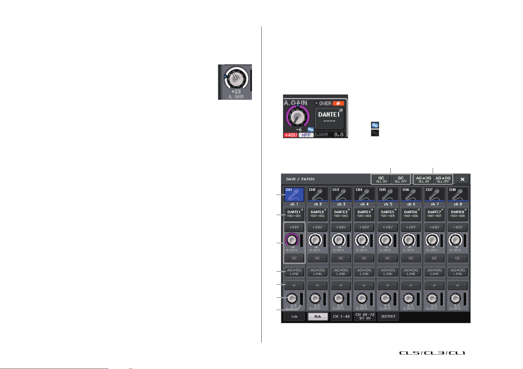
GAIN/PATCH window (1 ch)
HA (head amp) settings
You can make HA (Head Amp) related settings (phantom power on/off, gain, phase) for the
input channel.
• To adjust only the HA analog gain, use the GAIN knob in the SELECTED CHANNEL
section.
Setting the gain
Head amp settings are made in the GAIN/PATCH window.
STEP
1. Use the Bank Select keys in the Centralogic section to select the channels.
2. Press the HA/PHASE field in the OVERVIEW screen.
3. Press the 1ch or 8ch tab in the GAIN/PATCH window.
4. Make settings for the head amp.
29
1 Channel icon/Channel number/Channel name indicator
Indicates the channel icon, number, and name.
2 HA section
Appears if the head amp is patched to the input channel.
Reference Manual
Page 30
Input channels
: Link is on.
: Link is off.
1
2
3
6
8
4
5
97
NOTE
• If a slot is patched to the channel, the type of the slot/MY card and the slot meter will be displayed.
• If a rack is patched, the type of rack and type of effect will be displayed.
• +48V button
Switches head amp phantom power (+48V) on or off.
• A.GAIN (analog gain) knob
Indicates the analog gain of the head amp. Adjust the gain by using the
multifunction knobs. If the Gain Compensation function is turned on, an
indicator appears, showing the analog gain position at the time the
function was turned on.
•HA meter
Displays the level of the HA input signal.
• GC (Gain Compensation) ON/OFF button
Turns the Gain Compensation (gain correction function) on or off. If the Gain
Compensation function is turned on, the level of the signal output from the I/O device
to the audio network will be stabilized. For example, if the FOH console and the
monitoring console are sharing an I/O device, or if you are performing digital recording
via Dante connections, using this function will maintain the signal output at a constant
level from the I/O device to the network even if the analog gain value on the I/O device
is changed. If the Gain Compensation function is turned off, the analog gain and digital
gain will return to the level that was obtained when you turned on the function.
Therefore, the signal level on the digital network will remain the same.
• Gain compensation meter
Indicates the level of the signal output to the audio network after gain compensation.
3 INPUT PORT button
Indicates the port that is assigned to the channel. Press this button to display the PATCH
window, in which you can select a port to patch.
9 AG-DG LI NK button
If this button is turned on and GC (Gain Compensation) is enabled, you can link the
digital gain to the analog gain operation.
While you are controlling the analog gain, the Gain Compensation function enables you
to modify the level on your own console without affecting the level of other consoles.
0 AG-DG ALL ON/OFF buttons
You can turn on/off the link between the analog and digital gain for all input channels
simultaneously.
You can also view the link status in the SELECTED CHANNEL VIEW screen.
GAIN/PATCH window (8ch)
4 Icon / Channel name button
Indicates the channel number, icon, and name. Press this button to access the PATCH/
NAME window, in which you can patch the input port and specify the channel name.
5 Ø (Phase) button
Switches between normal and reverse phase settings of signals input from the head
amp.
6 D. GAIN (digital gain) knob
Indicates the digital gain value. Adjust the digital gain by using the multifunction knobs.
If the Gain Compensation function is turned on, digital gain will be used to adjust the
level of the signal input to the input channels.
7 Digital gain meter
Indicates the level after the signal passes through the digital gain.
8 GC ALL ON button/GC ALL OFF button
Switch Gain Compensation on or off for all input channels simultaneously.
30
Reference Manual
Page 31

Input channels
TAKE FROM PORT button
TAKE FROM CHANNEL button
1 Channel select button
Indicates the channel icon, number, and name. When you press this button, the
corresponding channel will become a target for operations in the SELECTED CHANNEL
section, and the corresponding [SEL] key will light.
2 PATCH button
Press this button to display the PORT SELECT window to patch the input port to the
input channel.
PORT SELECT window
• TAKE FROM PORT button
The HA settings of the port will take priority. Even if you change the patching, the HA
settings of the port will remain unchanged.
• TAKE FROM CHANNEL button
The HA settings of the channel will take priority. The HA settings of the port that had
been previously patched will be copied to the newly-patched port.
If the channel's HA settings are selected, the following HA settings will be copied from
the channel to the port that is patched. If you patch the input channel from an input that
does not have these settings (i.e., that does not have a HA), the default values will be
specified.
HA setting Default value
HA gain amount -6dB
HPF on/off Off
Phantom power on/off Off
Gain compensation on/off Off
3 HA section
Appears if the head amp is patched to the input channel.
NOTE
If the slot (for which the connection to the head amp is not recognized) is patched, the type of the
MY card will be displayed.
• +48V button
This button will appear for the input channel to which the head amp has been patched.
Press the button to switch phantom power (+48V) on or off.
• A.GAIN (analog gain) knob
Indicates the analog gain of the head amp. Press this knob to control the
parameter values using the multifunction knobs. If the Gain
Compensation function is turned on, an indicator appears, showing the
analog gain position at the time the function was turned on.
• Level meter
Indicates the input signal level .
• GC (Gain Compensation) button
Switches the Gain Compensation function on or off for that channel.
4 Ø (Phase) button
Switches between normal and reverse phase settings of signals input from the head
amp.
5 D. GAIN (digital gain) knob
Indicates the digital gain value. Press this knob to control the parameter values using the
multifunction knobs. If the Gain Compensation function is turned on, digital gain will
be used to adjust the level of the signal input to the input channels.
6 Digital gain meter
Indicates the level after the signal passes through the digital gain.
7 GC ALL ON button/GC ALL OFF button
Switch Gain Compensation on or off for all input channels simultaneously.
8 AG-DG LI NK button
If this button is turned on and GC (Gain Compensation) is enabled, you can link the
digital gain to the analog gain operation.
While you are controlling the analog gain, the Gain Compensation function enables you
to modify the level on your own console without affecting the level of other consoles.
9 AG-DG ALL ON/OFF buttons
You can turn on/off the link between the analog and digital gain for all input channels
simultaneously.
NOTE
If you're newly patching a previously-unpatched input channel, the default values will be specified
if the HA INFO field's TAKE FROM CHANNEL button is pressed.
31
Reference Manual
Page 32

Input channels
12 12
3
1
3
2
4
1
2
3
1
GAIN/PATCH window
(1-48, 49-72/ST IN (CL5), 49-64/ST IN (CL3), ST IN (CL1))
This window displays the head amp settings of the corresponding input channels. Here you
can also adjust the head amp gain in groups of the selected eight channels by using the
multifunction knobs in the Centralogic section.
1 Parameter select buttons
Switch parameters to view in the window.
• ANALOG GAIN...................... Analog gain
• DIGITAL GAIN ....................... Digital gain
• PAT CH ...................................Patch selection
2 GC ALL ON/GC ALL OFF buttons
Switch Gain Compensation on or off for all input channels simultaneously.
3 Channel select button
Selects the channel. You can select multiple channels simultaneously.
2 OVER indicator
Lights when a signal at the input port or from the rack output exceeds the full scale level.
This indicator is available only if an input channel is selected.
3 +48V indicator
Indicates the +48V on/off status for each channel.
4 Ø (Phase) indicator
Indicates the phase setting for each channel.
NOTE
If the input channel is patched to a slot for which the connection to the head amp is not
recognized, the knob
will not be displayed.
If the input channel is patched to a rack, the knob
If nothing is patched to the input channel, the knob
1 will be replaced with the slot/port number of the patch destination. 3
1 will be replaced with the port ID of the rack.
1 will be replaced with a dotted line “----”.
If you press the DIGITAL GAIN parameter select button:
1
GAIN knob
Indicates the digital gain setting for each channel. Press this knob to select a channel,
and then control the gain value using the multifunction knob.
2 OVER indicator
Lights when a signal at the input port or from the rack output exceeds the full scale level.
This indicator is available only if an input channel is selected.
3 Ø (Phase) indicator
Indicates the phase setting for each channel.
If you press the PATCH parameter select button:
If you press the ANALOG GAIN parameter select button:
GAIN knob
1
Indicates the analog gain setting for each channel. Press this knob to select a channel,
and then control the gain value using the multifunction knob. If the Gain Compensation
function is turned on, an indicator appears, showing the analog gain position at the time
the function was turned on.
32
1
PATCH button
Press this button to open the PORT SELECT window, in which you can select an input
port to patch to the channel.
Reference Manual
Page 33

Input channels
Relationship between analog and digital gain while Gain
Compensation is on
If Gain Compensation is on, adjusting the analog gain by a specific amount will cause the I/O
device to output to the audio network a signal that is attenuated by the same amount.
Therefore, the signals on the audio network will maintain a constant corrected level in the
digital domain.
For example, assume that the analog gain value has been set to +30 dB and Gain
Compensation is now turned on. Under this condition, if you raise the analog gain value to
+45 dB, the level of the signal sent to the audio network will stay at +30 dB (that is, attenuated
by -15 dB).
At this time, the gain of each signal input to the CL series console will be adjusted by the digital
gain parameter of the CL series console.
If the FOH console and the monitoring console are sharing one I/O device, adjusting the
analog gain on the FOH console will not affect the input level on the monitoring console,
because the level of the signal on the audio network is maintained at a constant level.
However, please note that if the signal is distorted due to a high level of analog gain, you must
first turn the Gain Compensation function off, set the gain to an appropriate input level, and
then turn the function back on. If you try to lower the analog gain level while the Gain
Compensation function is on, the signal on the audio network will be amplified by the same
amount due to the Gain Compensation function, and the signal will remain distorted.
NOTE
You can perform this operation by assigning the Gain Compensation on/off function to one of the
USER DEFINED keys.
• The panning of a signal sent from an input channel to the STEREO bus L/R is controlled by
the TO ST PAN knob. (Signals sent to the MONO bus are not affected by this knob.)
• The left/right volume balance of a signal sent from an ST IN channel to the STEREO bus is
controlled by this knob.
If PAN/BALANCE mode is set to PAN, you will be able to adjust the pan position of signals
sent to the STEREO bus L/R individually (page 34).
LCR mode
This mode sends input channel signals to three buses (STEREO (L/R) and MONO (C))
simultaneously.
• Signals sent from an input channel to the STEREO bus and MONO bus will be switched on
or off collectively.
• The CSR (Center Side Ratio) knob specifies the level ratio between signals sent from an
input channel to the STEREO (L/R) bus and to the MONO (C) bus.
• The TO ST PAN knob/BALANCE knob specifies the level of signals sent from an input
channel to the STEREO (L/R) bus and MONO (C) bus.
NOTE
If you want to monitor the signal of the STEREO bus or MONO bus through headphones or
similar devices, press the MONITOR button in the Function Access Area to select “LCR” as the
monitor source before you continue with the following procedure.
Sending the signal from an input channel to the STEREO/MONO bus
The STEREO bus and MONO bus are used to send signals to the main speakers. There are
two ways to send signals to the STEREO bus or MONO bus: ST/MONO mode and LCR
mode. You can select the mode individually for each channel. These two modes differ as
follows.
ST/MONO mode
This mode sends signals from the input channel to the STEREO bus and to the MONO bus
independently.
• Signals sent from an input channel to the STEREO bus and to the MONO bus can be
switched on or off individually.
33
Reference Manual
Page 34

Input channels
OVERVIEW screen TO STEREO/MONO window
1
2
3
6
5
4
7
ST/MONO mode LCR mode
STEP
1. Set the phantom power, gain, and phase of the input channel from which you want
to send the signal to the STEREO/MONO bus.
2. Use the Bank Select keys in the Centralogic section to select the input channel from
which you want to send the signal to the STEREO/MONO bus.
3. In the STEREO/MONO field, press a knob to select the channel you want to adjust in
the OVERVIEW screen, and then press the knob once again.
4. Use the MODE select button in the TO STEREO/MONO window to select either ST/
MONO mode or LCR mode for each channel.
5. In the MASTER section on the top panel, turn on the [ON] key for the STEREO
channel/MONO channel, and then raise the fader to an appropriate level.
6. In the INPUT section on the top panel, turn on the [ON] key for the input channel
you want to control, and then raise the fader to an appropriate position.
The subsequent steps will differ depending on whether ST/MONO mode or LCR mode was
selected for the channel in step 4.
Channels for which ST/MONO mode is selected
7. In the TO STEREO/MONO window, use the STEREO/MONO button to turn on/off
the signal sent from the input channel to the STEREO bus / MONO bus.
8. Use the TO ST PAN knob to set the panning of a signal sent from the input channel
to the STEREO bus.
Channels for which LCR mode is selected
7. In the TO STEREO/MONO window, use the LCR button to turn signals sent from the
input channel to the STEREO bus/MONO bus on or off collectively.
8. Use the CSR knob to adjust the level difference between the signals sent from that
channel to the STEREO (L/R) bus and to the MONO (C) bus.
9. Use the TO ST PAN knob to specify the panning of signals sent from the input
channel to the STEREO (L/R) bus and MONO (C) bus.
TO STEREO/MONO window (8ch)
Here you can control the on/off and pan/balance settings of the signal sent from input
channels to the STEREO (L/R) bus and MONO (C) bus, in groups of eight channels.
1 Channel select button
Selects the channel. You can select multiple channels simultaneously.
2 Mode LEDs
The LED of the currently-selected mode will light.
3 MODE select button
For a MONO channel, the mode can be switched between ST/MONO and LCR. For a
STEREO channel, the mode can be switched between PAN and BALANCE.
34
4 ST/MONO buttons
These buttons are on/off switches for signals that are sent from each channel to the
STEREO bus/MONO bus when the MONO button is set to ST/MONO mode.
5 Σ clipping indicator
Lights to indicate a signal is clipping at some point in the channel.
Reference Manual
Page 35

Input channels
1
2
3
4
6 TO ST PAN/TO ST BALANCE knob
For MONO channels, this acts as a PAN knob that adjusts the left/right panning of
signals sent to the STEREO bus. For STEREO channels, this acts as a PAN knob, and also
as a BALANCE knob that adjusts the volume of the left and right signals sent to the
STEREO bus. To adjust the value, press the knob to select it, and then operate the
corresponding multifunction knob.
7 Ta bs
Enable you to switch between windows.
8
9
8 LCR button
If the MODE button is set to LCR mode, this button is displayed instead of 4. This
button is an overall on/off button for signals sent from a channel to the STEREO bus and
MONO bus. If this button is off, no signals will be sent from the corresponding input
channel to the STEREO bus or MONO bus.
9 CSR knob
Adjusts the relative level of signals sent from the channel to the STEREO (L/R) bus and
to the MONO (C) bus, in the range of 0 - 100%. To adjust the value, press the knob to
select it, and then operate the corresponding multifunction knob. (page 36).
TO STEREO/MONO window
(CH 1-48, CH 49-72/ST IN (CL5), CH 49-64/ST IN (CL3), ST IN
(CL1))
Adjusts the status of a signal sent from the corresponding input channel to the STEREO/
MONO bus. Here you can also adjust the pan or balance in groups of the selected eight
channels.
1 Channel select button
Selects the channel. You can select multiple channels simultaneously.
35
2 Σ clipping indicator
Lights to indicate a signal is clipping at some point in the channel.
3 TO ST PAN/TO ST BALANCE knob
Adjusts the panning or balance.
To adjust the value, press the knob to select it, and then operate the corresponding
multifunction knob.
If the signal reaches the overload point at any meter detection point in that channel, the
Σ indicator to the right of the knob will light.
4 ST/MONO indicator
If a channel is set to ST/MONO mode, these indicators will individually indicate the on/
off status of signals sent from the channel to the STEREO bus/MONO bus.
If that channel is set to LCR mode, the LCR indicator will be displayed in this location.
The LCR indicator indicates the on/off status of all signals sent from that channel to the
STEREO bus/MONO bus.
Reference Manual
Page 36

Input channels
TO ST PAN knob
Signal sent to the STEREO (L) bus
Signal sent to the STEREO (R) bus
Signal level
TO ST BALANCE knob
Signal sent from the STEREO (L)
channel to the STEREO (L) bus
Signal level
CLR
TO ST BALANCE knob
Signal sent from the STEREO (R)
channel to the STEREO (R) bus
Signal level
CLR
PAN kn o b
Signal sent to the MONO (C) bus
Signal sent to the STEREO (L) bus
Signal sent to the STEREO (R) bus
Signal level
CLR
TO ST BALANCE knob
Signal sent from the ST IN (L) channel to
the MONO (C) bus
Signal sent from the ST IN (L) channel to
the STEREO (L) bus
Signal level
TO ST BALANCE knob
Signal sent from the ST IN (R) channel to
the MONO (C) bus
Signal sent from the ST IN (R) channel to
the STEREO (R) bus
Signal level
Signal level when LCR mode is selected
If LCR mode is selected, the signal level sent to the STEREO (L/R) bus and MONO (C) bus
will vary according to the settings of the CSR knob and the TO ST PAN knob.
When the CSR knob is set to 0% (MONO channel)
The TO ST PAN knob operates as a conventional PAN knob, and no signal is sent to the
MONO (C) bus.
CLR
When the CSR knob is set to 0% (STEREO channel)
The TO ST BALANCE knob operates as a conventional BALANCE knob, and no signal is
sent to the MONO (C) bus.
When the CSR knob is set to 100%
When the CSR knob is set to 100% (ST IN channel)
CLR
36
CLR
Reference Manual
Page 37

Sending a signal from an input channel to a MIX/
SELECTED CHANNEL
VIEW screen
MATRIX bus
The MIX buses are used mainly for the purpose of sending signals to foldback speakers on
stage, or to external effect processors. The MATRIX buses are used to produce a mix that is
independent of the STEREO bus or MIX buses, and is typically sent to a master recorder or
to a backstage monitoring system.
You can send a signal from an input channel to a MIX/MATRIX bus in the following three ways.
Using the Selected Channel section
With this method, you use the knobs in the SELECTED CHANNEL section to adjust the send
levels to the MIX/MATRIX buses. When using this method, signals sent from a specific input
channel to all MIX/MATRIX buses can be adjusted collectively.
Using the Centralogic section
With this method, you use the multifunction knobs in the Centralogic section to adjust the level
of signals sent to the MIX/MATRIX buses. When using this method, the signals sent from eight
consecutive input channels to a specific MIX/MATRIX bus can be adjusted simultaneously.
Using the faders (SENDS ON FADER mode)
With this method, you switch the CL series unit to SENDS ON FADER mode, and use the
faders on the top panel to adjust the level of signals sent to the MIX/MATRIX buses. When
using this method, signals sent from all input channels to a specific MIX/MATRIX bus can be
adjusted simultaneously.
Input channels
NOTE
• If you want to monitor the signal being sent to a specific MIX/MATRIX bus, use the Bank Select
keys in the Centralogic section to access the corresponding MIX/MATRIX channel, and then
press the appropriate [CUE] key in the Centralogic section.
MIX buses can be either a FIXED type whose send level is fixed, or a VARI type whose send
level is variable. The MATRIX buses are all VARI type. You can switch between FIXED and
VARI types for each two adjacent odd/even-numbered MIX buses. To do so, press the SETUP
button and then the BUS SETUP button to open the BUS SETUP window.
If the MIX bus is a FIXED type
Using the Selected Channel section
This section explains how to use the knobs in the SELECTED CHANNEL section to adjust
the send levels of signals sent from a specific input channel to all MIX/MATRIX buses.
STEP
1. Assign an output port to each MIX/MATRIX bus to which you want to send signals,
and connect your monitor system, external effects processor, or other device to the
corresponding output port.
2. Use the [SEL] keys on the top panel to select the input channel that will send signals
to the MIX/MATRIX bus.
3. Press one of the knobs in the Selected Channel section.
4. Turn on the ON button in the SEND field in the SELECTED CHANNEL VIEW screen.
5. Turn on the TO MIX/MATRIX SEND ON/OFF button for the send-destination MIX
bus.
6. Use the MIX/MATRIX SEND LEVEL knob in the SELECTED CHANNEL section to adjust
the send levels to the MIX/MATRIX buses.
A gray circle is displayed instead of the TO MIX SEND LEVEL knob, and you cannot
adjust the send level.
For a VARI type MIX bus or a MATRIX bus
The TO MIX SEND LEVEL knob is displayed in the same color as the corresponding knob
in the SELECTED CHANNEL section. In this case, you can use the corresponding knob in
the SELECTED CHANNEL section to adjust the send level.
37
Reference Manual
Page 38

If the MIX/MATRIX bus is a stereo bus
OVERVIEW screen
You can link the main parameters of two adjacent odd/even-numbered MIX/MATRIX
buses. If the send-destination MIX/MATRIX bus is assigned as stereo, the left knob of the
two adjacent TO MIX/MATRIX SEND LEVEL knobs will operate as the TO MIX/MATRIX
PAN knob. (If BALANCE mode is selected in the TO STEREO/MONO window, it will
operate as a BALANCE knob).
NOTE
• For a MONO channel, the right knob will adjust the common send level to the two MIX/MATRIX
buses, and the left knob will adjust the panning between the two MIX/MATRIX buses. Rotating
the left TO MIX/MATRIX SEND LEVEL knob counter-clockwise will increase the amount of signal
sent to the odd-numbered MIX/MATRIX bus, and rotating it clockwise will increase the amount
sent to the even-numbered MIX/MATRIX bus.
• For a STEREO channel, if BALANCE mode has been selected on the TO STEREO/MONO
window, the right knob adjusts the common send level for the two MIX/MATRIX buses, and the
left knob adjusts the volume balance of the left and right signals sent to the two MIX/MATRIX
buses. Rotating the left TO MIX/MATRIX SEND LEVEL knob counter-clockwise will increase the
amount of signal sent from the L-channel to the odd-numbered MIX/MATRIX bus, and rotating it
clockwise will increase the amount sent from the R-channel to the even-numbered MIX/MATRIX
bus. If PAN mode has been selected in the TO STEREO/MONO window, the left knob will function
as the PAN knob. The right knob function will be the same as in BALANCE mode.
Input channels
NOTE
• If you want to monitor a signal being sent to a specific MIX/MATRIX bus, use the Bank Select
keys to assign the corresponding MIX channel to the Centralogic section, and then press the
[CUE] key for that MIX/MATRIX channel.
• In the OVERVIEW screen, you can also adjust the send level of the signal sent to the MIX/
MATRIX buses. To do so, press the SEND LEVEL knob for the MIX/MATRIX that you want to
adjust, and then use the multifunction knob in the Centralogic section to adjust it.
MIX SEND/MATRIX SEND window
13 32 1 2
Using the Centralogic section
You can use the multifunction knobs in the Centralogic section to adjust the send level of
signals sent from eight consecutive input channels to a specific MIX/MATRIX bus.
STEP
1. Assign an output port to each MIX/MATRIX bus to which you want to send signals,
and connect your monitor system, external effects, or other device to the
corresponding output port.
2. Use the Bank Select keys in the Centralogic section to select the channels that you
want to control.
3. In the OVERVIEW scree, press the TO MIX/MATRIX SEND LEVEL knob to select the
desired send-destination MIX/MATRIX bus, and then press it again.
4. Use the SEND ON/OFF button in the MIX SEND/MATRIX SEND screen to turn the
signal on/off and to adjust the send level.
4
5
6
7
8 8
9
1 ALL PRE button
Sets the send point to PRE. (The send point is the point at which signals are sent from
all send-source channels - including the input and output channels - to the selected send
destination.) At this time, the PRE/POST button will light.
2 ALL POST button
Sets the send point to POST. (The send point is the point at which signals are sent from
all send-source channels - including the input and output channels - to the selected send
destination.) At this time, the PRE/POST button will turn off.
3 Send destination indicator
Indicates the currently-selected send destination.
38
4
5
6
7
9
Reference Manual
Page 39

Input channels
Function
access area
4 Send destination select buttons
Select MIX/MATRIX buses as the send destination.
5 Channel select button
Selects the send-source channel that you wish to control. The current channel icon,
number, and color appear on the button, and the channel name appears below the
button.
6 PRE/POST button
Switches the send point of each send-source channel between PRE and POST. If the
button is lit, the send point is set to PRE.
NOTE
• If the PRE/POST button is on, you can also select PRE EQ (immediately before the EQ) or PRE
FADER (immediately before the fader) for each MIX/MATRIX bus. This setting is made in the BUS
SETUP window (page 223).
• The PRE/POST button is not displayed for FIXED type MIX buses.
7 SEND ON/OFF button
Switches the send of each send-source channel on or off.
8 SEND PAN/BALANCE knob
Sets the panning or balance of signals sent to the stereo send destination. If the send
destination is monaural or set to FIXED, this knob will not appear.
If the send source is monaural, this knob functions as a PAN knob.
If the send source is stereo, you can use PAN/BALANCE mode setting
in the TO STEREO/MONO window to select whether PAN/BALANCE
will function as a PAN or BALANCE knob. The knob for the mode
selected here will appear.
Using the faders (SENDS ON FADER mode)
You can use the faders on the top panel to adjust signals that are sent from all input channels
to a specific MIX/MATRIX bus.
STEP
1. Assign an output port to each MIX/MATRIX bus to which you want to send signals,
and connect your monitor system, external effects, or other device to the
corresponding output port.
2. In the Function Access Area, press the SENDS ON FADER button.
3. Use the MIX/MTRX ON select buttons in the Function Access Area to switch between
MIX 1-16 and MIX 17-24/MATRIX.
4. Use the MIX/MATRIX bus selection buttons in the Function Access Area to select the
send-destination MIX/MATRIX bus.
5. Use the faders in the Channel Strip section on the top panel to adjust the send level
of signals routed from the input channels to the selected MIX/MATRIX bus.
9 SEND LEVEL knob
Indicates the level of signals sent to the selected send destination. Press this knob to
control the level using the multifunction knobs.
If the send destination is set to FIXED, only a gray circle will appear.
39
NOTE
• Press the SENDS ON FADER button to switch to SENDS ON FADER mode. The most recently
selected group of MIX/MATRIX buses will be assigned to the Centralogic section. The faders in
the Channel Strip section and Master section will move to indicate the send level of signals that
are routed from each channel to the currently-selected MIX/MATRIX bus.
• Alternatively, you can press a SEND LEVEL knob in the SELECTED CHANNEL section to
display a window from which you can select the send-destination MIX/MATRIX bus.
• You can also select a MIX/MATRIX bus by using the Bank Select keys and the [SEL] keys in the
Centralogic section. If you select the MIX buses or MATRIX buses by pressing the [SEL] keys,
the setting of the MIX/MTRX ON FADER switch button will be changed automatically.
• If you press the currently-selected MIX/MATRIX bus select button again, cue monitoring will be
turned on for the related MIX/MATRIX channel. This method is convenient if you want to monitor
the signal that is being sent to the selected MIX/MATRIX bus.
Reference Manual
Page 40

Input channels
CHANNEL ON
CHANNEL OFF
Channel number
display
• You can assign the SENDS ON FADER function to a USER DEFINED key. This lets you quickly
switch to SENDS ON FADER mode for a specific MIX/MATRIX bus, and quickly switch back
again.
SENDS ON FADER mode
1
Channel name display indication
In SENDS ON FADER mode, ON/OFF is indicated for the channel.
3
On the PREFERENCE page in the USER SETUP pop-up window, the channel number is
shown if NAME DISPLAY is set to “NAME ONLY”.
2
1 MIX/MTRX ON FADER switch button
2 MIX/MATRIX bus select buttons
3 Close button
Use this button to switch between MIX 1-16 and MIX 17-24/MATRIX for the bus
displayed in the Function Access Area.
Select the buses that will be controlled by the faders.
Closes the SENDS ON FADER mode.
Correcting delay between channels (Input Delay)
This section explains how to correct delay between input channels by using the Input Delay
function.
This function is useful when you want to correct the phase variance caused by microphone
locations on the stage, to add depth to the sound by using phase variance, or to correct a
delay (a time gap) that may exist between video and audio that are sent from a site for
broadcast on TV.
STEP
1. Use the [SEL] keys on the top panel to select the input channel that will send signals
to the MIX/MATRIX bus.
2. Press one of the knobs in the Selected Channel section.
3. Press the INPUT DELAY field in the SELECTED CHANNEL VIEW screen.
4. Press the 8 ch tab in the INPUT DELAY screen.
5. Use the on-screen buttons and the multifunction knobs to set the delay.
40
Reference Manual
Page 41

NOTE
SELECTED CHANNEL
VIEW screen
INPUT DELAY screen
1 5
2
3
4
If you are viewing the 8 ch INPUT DELAY screen, you can use the Bank Select keys in the
Centralogic section to switch the channels being controlled in groups of eight.
INPUT DELAY screen (8ch)
You can set the on/off status and the value of the input channel delay.
Input channels
2 Channel select button
The currently-selected input channel is indicated in blue. Press the button to select the
channel.
3 Delay setting knob (input channels only)
You can use the multifunction knob to adjust the delay. You can view the current value
immediately above the knob (always shown in unit of ms) and below the knob (shown
using the currently-selected scale). If ms (millisecond) has been selected for the DELAY
SCALE, nothing will appear above the knob.
4 Ta bs
Enable you to switch between windows.
5 Close button
Closes the screen.
1 DELAY SCALE button
Press the button to display the DELAY SCALE window, in which you can select the unit
for the delay time.
There are five delay scales: meter (meter/sec), feet (feet/sec), sample (number of
samples), ms (milliseconds), and frame (frames). If you select frame as the units, you can
choose from six frame rates: 30, 30D, 29.97, 29.97D, 25, and 24. In this case, fr will
appear as the units in the channel name display.
41
Reference Manual
Page 42

Input channels
1
2
3
STEREO IN Lch
STEREO IN Rch
STEREO R
STEREO L
ON
ON
PAN/BAL
PAN/BAL
STEREO IN Lch
STEREO IN Rch
STEREO R
STEREO L
ON
ON
PAN/BAL
PAN/BAL
INPUT DELAY (CH 1-48, CH 49-72/ST IN (CL5),
CH 49-64/ST IN (CL3), ST IN (CL1))
1 DELAY SCALE button
Press the button to display the DELAY SCALE window, in which you can select the unit
for the delay time.
Additional functions for stereo input channels
With V3, you can temporarily set the signals sent to a stereo input channel as mono. You can
select from the following three settings.
L-MONO
Only the L channel is temporarily set as a mono signal.
R-MONO
Only the R channel is temporarily set as a mono signal.
2 Channel select button
3 Delay setting knob (input channels only)
Lights to indicate the currently-selected input channel. Press the button to select the
channel.
Press this knob to adjust the value using the multifunction knob. You can view the
current value immediately above the knob (always shown in unit of ms) and below the
knob (shown using the currently-selected scale).
NOTE
If ms (millisecond) has been selected for the DELAY SCALE, nothing will appear to the right of
the knob.
42
Reference Manual
Page 43

Input channels
STEREO IN Lch
STEREO IN Rch
STEREO R
STEREO L
ON
ON
PAN/BAL
PAN/BAL
1
2
LR-MONO
The signals sent to both channels are temporarily set as mono signals.
Setting procedure
If a stereo input channel is selected, the SELECTED CHANNEL VIEW screen will appear as
shown below.
1 LR-MONO SELECT field
Select one of the four buttons. The button you select lights up, and the others go off.
Normal STEREO setting
L-M ONO
R-MONO
LR-MONO
If a stereo input channel is selected, the OVERVIEW screen will appear as shown below.
2 LR-MONO SELECT button
This a toggle button. The setting switches each time the button is pressed.
43
Reference Manual
Page 44

Input channels
SETUP screen
SURROUND SETUP screen
1
2
4
5
7
3
3
6
Surround output for input channels
Setting Surround mode
You can enable surround mixes by changing bus settings to Surround mode.
STEP
1. In the Function Access Area, press the SETUP button.
2. In the SETUP screen, press the SURROUND SETUP button (page 187).
3. Press the 5.1 SURROUND button.
4. Assign channels to MIX 1 - 6 for surround output.
5. Press the APPLY button.
6. Press the OK button in the confirmation dialog box.
SELECTED CHANNEL VIEW screen
If you set a bus to Surround mode in BUS SETUP, the SELECTED CHANNEL VIEW screen
appears as shown below.
NOTE
When you switch from Stereo mode to Surround mode, the signals for MIX1/2, 3/4, and 5/6
change to MONO x2.
However, when you switch from Surround mode to Stereo mode, the signals for MIX1/2, 3/4, and
5/6 remain as MONO x2.
44
1 L/R knob
This parameter is used to set the left/right surround position.
Use the SEND knob (MIX 1) of the Selected Channel section to make adjustments.
2 F/R knob
This parameter is used to set the front/rear surround position.
Use the SEND knob (MIX 3) of the Selected Channel section to make adjustments.
3 Assign buttons for each bus
If there is a bus from which you do not want to output an audio signal, turn that button
off.
Reference Manual
Page 45

4 DIV knob
Adjusting L/R
3
2
1
Adjusting F/R
This determines how the Center signal is fed to the Left, Right, and Center channels.
When set to 0, the Center signal is fed only to the Left and Right channels. When set to
50, the Center signal is fed equally to the Left, Right, and Center channels. When set to
100, it’s fed to only the Center channel (i.e., Real Center).
Use the SEND knob (MIX 5) of the Selected Channel section to make adjustments.
5 LFE knob
This sets the level of the LFE (Low Frequency Effects) Channel.
Use the SEND knob (MIX 6) of the Selected Channel section to make adjustments.
6 Surround position
The color of the ball shown here changes depending on whether the surround position
is a hard pan (panned fully left or right) or any other setting.
Hard pan: Red
Any other setting: Orange
7 Surround graph
This graph shows the surround positions. Press here to open the SURROUND PAN 1CH
screen.
OVERVIEW screen
If you set a bus to Surround mode in BUS SETUP, the OVERVIEW screen appears as shown
below.
Input channels
1 Surround graph
This graph shows the surround positions. Press here to open the SURROUND PAN 1CH
screen.
1
2
3
45
2 L/R F/R switch button
Use this toggle button to switch between the screen for adjusting L/R and the screen for
adjusting F/R.
Use the SEND knob (MIX 5) of the Selected Channel section to make adjustments.
3 LFE knob
This sets the level of the LFE (Low Frequency Effects) Channel.
Use the SEND knob (MIX 6) of the Selected Channel section to make adjustments.
Reference Manual
Page 46

Input channels
>9
1
38
6 754
3
2
Adjusting L/R
SURROUND PAN 1CH screen
If you set a bus to Surround mode in BUS SETUP, the SURROUND PAN 1CH screen appears
as shown below. This screen is displayed when you press the pan display area in the
SELECTED CHANNEL VIEW screen or the OVERVIEW screen.
6 DIV knob
This determines how the Center signal is fed to the Left, Right, and Center channels.
When set to 0, the Center signal is fed only to the Left and Right channels. When set to
50, the Center signal is fed equally to the Left, Right, and Center channels. When set to
100, it’s fed to only the Center channel (i.e., Real Center).
Use the SEND knob (MIX 5) of the Selected Channel section to make adjustments.
7 LFE knob
This sets the level of the LFE (Low Frequency Effects) Channel.
Use the SEND knob (MIX 6) of the Selected Channel section to make adjustments.
8 DEFAULT button
Press this button to reset all parameters to the initial values.
9 COPY button
All parameter settings will be copied in buffer memory.
0 PASTE button
Press this button to paste the copied settings from buffer memory to the current
settings. If no valid data has been copied in the buffer memory, nothing will happen.
SURROUND PAN screen (CH 1-48, CH 49-72/ST IN (CL5), CH 4964/ST IN (CL3), ST IN (CL1))
If you set a bus to Surround mode in BUS SETUP, the SURROUND PAN screen (CH 1-48,
CH 49-72/ST IN (CL5), CH 49-64/ST IN (CL3), ST IN (CL1)) appears as shown below. This
screen is displayed when you press the pan display area in the SELECTED CHANNEL VIEW
screen or the OVERVIEW screen.
1 Surround graph
This graph shows the surround positions.
2 Surround position
You can set the surround position by touching and dragging the ball in the graph.
3 Assign buttons for each bus
All of these buttons are turned on by default. If there is a bus from which you do not
want to output an audio signal, turn that button off.
4 L/R knob
This parameter is used to set the left/right surround position.
Use the SEND knob (MIX 1) of the Selected Channel section to make adjustments.
5 F/R knob
This parameter is used to set the front/rear surround position.
Use the SEND knob (MIX 3) of the Selected Channel section to make adjustments.
46
1
2
Reference Manual
Page 47

Input channels
Adjusting F/R
1
2
2
1
TO STEREO/MONO screen
If you set a bus to Surround mode in BUS SETUP, the TO STEREO/MONO 8CH screen for
MIX 1-8 appears as shown below. MIX 1-6 are for setting downmixes.
1 Surround graph
This graph shows the surround positions.
2 L/R F/R switch button
Use this toggle button to switch between the screen for adjusting L/R and the screen for
adjusting F/R.
Use the SEND knob (MIX 5) of the Selected Channel section to make adjustments.
1 L/R buttons
Use these buttons to set the output destination.
2 Coefficient Setting fader
Use this fader to set the downmix coefficient. There is a ∑ clip indicator.
47
Reference Manual
Page 48

The TO STEREO/MONO OUTPUT screen appears as shown below. Parameters cannot be
LIBRARY button
set for MIX 1 - 6; this screen is only for displaying parameters.
Channel library operations
Input channels
The “INPUT CHANNEL LIBRARY” enables you to store and recall various parameters
(including the head amp settings) for input channels.
To recall a library item, press the corresponding LIBRARY button in the SELECTED
CHANNEL VIEW screen. For details on using the library, refer to the “Using libraries” section
in the separate Owner's Manual.
48
Reference Manual
Page 49

OUTPUT channels
MIX
12 23
24STLR
M
O
N
O
(C)
MATRIX
12 78
CUE
LR
MIX
12 23
24STLR
M
O
N
O
(C)
MATRIX
12 78
CUE
LR
OUTPUT channels
This chapter explains output channels (MIX channels, MATRIX channels, STEREO channels,
MONO channels).
Signal flow for output channels
The output channel section takes the signals sent from the input channels to the various
buses, processes them with EQ and dynamics, and sends them to output ports or other
buses. The following types of output channels are provided.
MIX channels
These channels process signals sent from input channels to MIX buses, and output them to
the corresponding output port, MATRIX bus, STEREO bus, or MONO (C) bus.
M
O
N
MIX
12 23
24STLR
O
(C)
MATRIX
12 78
CUE
LR
STEREO channel/MONO (C) channel
Each of these channels process the signal sent from the input channels to the STEREO bus
or MONO (C) bus, and send it to the corresponding output port or MATRIX bus. If input
channels are in LCR mode, the STEREO (L/R) channels and the MONO (C) channel can be
used together as a set of three output channels.
MATRIX channel
These channels process the signals sent from input channels, MIX channels, and STEREO/
MONO channels to MATRIX buses, and send them to the corresponding output ports.
• 4 BAND EQ (4 band equalizer)
A parametric EQ with four bands: HIGH, HIGH MID, LOW MID, and LOW.
• DYNAMICS 1
This is a dynamics processor that can be used as a compressor, expander, or compander.
•LEVEL
Adjusts the output level of the channel.
•ON (On/off)
Turns the output channel on or off. If this is off, the corresponding channel will be
muted.
49
Reference Manual
Page 50

OUTPUT channels
OVERVIEW screen PATCH/NAME screen
• MATRIX ON/OFF (MATRIX send on/off)
This is an on/off switch for signals sent from the MIX channels, STEREO (L/R) channel,
or MONO (C) channel to each MATRIX bus.
• MATRIX (MATRIX send level)
This adjusts the send level of the signal sent from the MIX channels, STEREO (L/R)
channel, or MONO (C) channel to each MATRIX bus 1 - 8. For the position from which
the signal will be sent to the MATRIX bus, you can choose either immediately before the
fader, or immediately after the [ON] key.
If the send-destination MATRIX bus is set to stereo, you can use the PAN knob to adjust
the panning between the two MATRIX buses. If the send-source is a stereo MIX channel
or the STEREO channel, use the BALANCE knob to adjust the volume balance of the left
and right channels sent to the two MATRIX buses.
•INSERT
You can patch the desired output/input ports to insert an external device such as an
effect processor. You can switch the insert-out and insert-in locations.
• METER
Indicates the level of the output channel.
You can switch the position at which the level is detected.
• KEY IN (MIX channels 21-24 only)
You can send the output signals of MIX channels 21 - 24 to Dynamics processors and
use them as key-in signals to control the Dynamics.
• RACK IN PATCH
Patches the output signal of an output channel to an input of the rack.
• OUTPUT PATCH
Assigns an output port to an output channel.
• MONITOR SELECT
Selects the output signal of an output channel as a monitor source.
Specifying the channel name/icon
STEP
1. Use the Bank Select keys in the Centralogic section to select the output channels.
2. On the OVERVIEW screen, press the channel number/channel name field of the
channel for which you want to specify a channel name/icon.
3. Follow the steps for the input channels (page 27).
50
Reference Manual
Page 51

Sending signals from MIX channels to the STEREO/
OVERVIEW screen TO STEREO/MONO window
ST/MONO mode LCR mode
MONO bus
There are two ways to send signals to the STEREO bus or MONO bus: ST/MONO mode and
LCR mode. You can select the mode individually for each channel. Features of each mode
are the same as for input channels.
STEP
1. Use the Bank Select keys in the Centralogic section to select the MIX channel from
which you want to send the signal to the STEREO/MONO bus.
2. In the STEREO/MONO field, press a knob to select the channel you want to adjust in
the OVERVIEW screen, and then press the knob once again.
3. Use the MODE select button in the TO STEREO/MONO window to select either ST/
MONO mode or LCR mode for each channel.
4. In the MASTER section on the top panel, turn on the [ON] key for the STEREO
channel/MONO channel, and then raise the fader to an appropriate level.
5. In the Centralogic section, press an OUTPUT bank select key so that the MIX
channels you want to control are assigned to the Centralogic section.
6. Turn on the [ON] keys for those channels, and use the fader in the Centralogic
section to raise the master level of the MIX channel to an appropriate position.
The subsequent steps will differ depending on whether ST/MONO mode or LCR mode was
selected for the channel in step 3.
Channels for which ST/MONO mode is selected
7. In the TO STEREO/MONO window, use the ST/MONO button to turn a signal sent
from the MIX channel to the STEREO bus/MONO bus on or off .
8. Use the TO ST PAN knob to set the panning of the signal sent from the MIX channel
to the STEREO bus.
Channels for which LCR mode is selected
7. Turn on the LCR button in the TO STEREO/MONO window.
8. Press the CSR knob to select it, and use multifunction knobs 1 - 8 to adjust the level
difference between signals sent from that channel to the STEREO (L/R) bus and to
the MONO (C) bus.
9. Press the TO ST PAN knob to select it, and use multifunction knobs 1 - 8 to adjust
the panning of signals sent from the MIX channel to the STEREO (L/R) bus and
MONO (C) bus, and the level balance of signals sent to the MONO (C) bus and
STEREO (L/R) bus.
OUTPUT channels
NOTE
Refer to “Signal level when LCR mode is selected” (page 36) for details on how the signal level
sent from an LCR mode MIX channel to each bus will change according to the operation of the
TO ST PAN knob.
TO STEREO/MONO window(8ch)
You can control the on/off and pan/balance settings of the signal sent from MIX channels to
the STEREO (L/R) bus and MONO (C) bus, in groups of eight channels.
1
2
3
8
4
5
6
7
9
51
1 Channel select button
Selects the channel. You can select multiple channels simultaneously.
2 Mode LEDs
The LED of the currently-selected mode will light.
Reference Manual
Page 52

OUTPUT channels
1
2
3
4
3 MODE select button
Press this button repeatedly to toggle between ST/MONO and LCR.
4 ST/MONO buttons
These buttons are individual on/off switches for signals that are sent from each channel
to the STEREO bus/MONO bus when the MONO button is set to ST/MONO mode.
5 Σ clipping indicator
Lights to indicate a signal is clipping at some point in the channel.
6 TO ST PAN/TO ST BALANCE knob
If the type of the MIX channel signal is MONO, this knob will function as a PAN knob
that adjusts the left and right pan position of the signal sent to the STEREO bus. If the
type of MIX channel signal is STEREO, this knob will function as a BALANCE knob that
adjusts the volume level balance of left and right signals sent to the STEREO bus. To
adjust the value, press the knob to select it, and then operate the corresponding
multifunction knob.
7 Ta bs
Enable you to switch between windows.
8 LCR button
This button is an overall on/off button for signals sent from a channel to the STEREO bus
and MONO bus. If this button is off, no signals will be sent from the corresponding input
channel to the STEREO bus or MONO bus.
9 CSR knob
Adjusts the relative level of signals sent from the channel to the STEREO (L/R) bus and
to the MONO (C) bus, in the range of 0 - 100%. To adjust the value, press the knob to
select it, and then operate the corresponding multifunction knob.
TO STEREO/MONO screen
(CH 1-48, CH 49-72/ST IN (CL5), CH 49-64/ST IN (CL3),
ST IN (CL1), OUTPUT)
Adjusts the status of a signal sent from the corresponding channel to the STEREO/MONO
bus. Here you can also adjust the pan or balance in groups of the selected eight channels.
1 Channel select button
Selects the channel. You can select multiple channels simultaneously.
52
2 Σ clipping indicator
Lights to indicate a signal is clipping at some point in the channel.
3 TO ST PAN/TO ST BALANCE knob
Adjusts the panning or balance.
To adjust the value, press the knob to select it, and then operate the corresponding
multifunction knob.
If the signal level reaches the overload point at any meter detection point in that
channel, the Σ clipping indicator to the right of the knob will light.
4 ST/MONO indicator
If a channel is set to ST/MONO mode, these indicators will individually indicate the on/
off status of signals sent from the channel to the STEREO bus/MONO bus.
If that channel is set to LCR mode, the LCR indicator will be displayed in this location.
The LCR indicator indicates the on/off status of all signals sent from that channel to the
STEREO bus/MONO bus.
Reference Manual
Page 53

Sending signals from MIX channels and STEREO/
SELECTED CHANNEL VIEW
screen
MONO channels to MATRIX buses
You can send a signal from a MIX or STEREO/MONO channel to MATRIX buses 1 - 8 in the
following t wo ways.
Using the Selected Channel section
With this method, you use the knobs in the SELECTED CHANNEL section to adjust the send
levels to the MATRIX buses. This method allows you to simultaneously control signals sent
from a specific MIX, STEREO (L/R), or MONO (C) channel to all MATRIX buses.
Using the Centralogic section
With this method, you use the multifunction knobs in the Centralogic section to adjust the
send levels to the MATRIX buses. This method allows you to simultaneously control signals
sent from up to eight MIX, STEREO (L/R), or MONO (C) channels to a specific MATRIX bus.
Using the Selected Channel section
Use the knobs in the SELECTED CHANNEL section to adjust the send level of signals sent
from the desired MIX, STEREO (L/R) or MONO (C) channel to all MATRIX buses.
OUTPUT channels
NOTE
• You can also use the [SEL] key in the MASTER section to directly select the STEREO/MONO
channels.
• If you want to monitor the signal being sent to a specific MATRIX bus, use the Bank Select keys
in the Centralogic section to access the corresponding MIX/MATRIX channel, and then press the
appropriate [CUE] key in the Centralogic section.
STEP
1. Assign an output port to the MATRIX bus to which you want to send signals, and
connect an external device.
2. Using the Bank Select keys in the Centralogic section, assign the desired MIX
channels or the STEREO/MONO channels to the Centralogic section.
3. Use the [SEL] keys of the Centralogic section to select the input channel that will
send signals to the MATRIX buses.
4. Press one of the knobs in the Selected Channel section.
5. In the SELECTED CHANNEL VIEW screen, turn on the TO MATRIX SEND ON/OFF
button for the send-destination MATRIX bus.
6. Use the MIX/MATRIX SEND LEVEL knob in the SELECTED CHANNEL section to adjust
the send levels to the MATRIX buses.
Using the Centralogic section
This method lets you use the multifunction knobs (in the Centralogic section) to
simultaneously adjust the send levels from the eight channels selected in the Centralogic
section to the desired MATRIX bus.
STEP
1. Assign an output port to the MATRIX bus to which you want to send signals, and
connect an external device to that output port.
2. Use the Bank Select keys in the Centralogic section to select the channels that you
want to control.
3. In the OVERVIEW screen, press the TO MATRIX SEND LEVEL knob to select the
desired send-destination MATRIX bus, and then press it again.
4. Set the SEND ON/OFF button to ON, and use the SEND LEVEL knob to adjust the
send level.
53
Reference Manual
Page 54

NOTE
OVERVIEW screen
• If you want to monitor signals being sent to a specific MATRIX bus, use the Bank Select keys to
access the corresponding MATRIX channel in the Centralogic section, and then press the [CUE]
key for that MATRIX channel.
• If you again press the currently-selected MATRIX bus select button, cue monitoring will be turned
on for the related MATRIX channel. This method is convenient if you want to monitor a signal that
is being sent to the selected MATRIX bus.
• In the OVERVIEW screen, you can also adjust the send level of the signal sent to the MIX/
MATRIX buses. To do so, press the SEND LEVEL knob for the TO MIX/MATRIX that you want to
adjust, and then use the multifunction knob in the Centralogic section to adjust it.
MATRIX SEND screen
13 2
OUTPUT channels
2 ALL POST button
Sets the send point to POST. (The send point is the point at which signals are sent from
all send-source channels - including the input and output channels - to the selected send
destination.)
3 Send destination indicator
Indicates the currently-selected send destination.
4 Send destination select buttons
Select MIX/MATRIX buses as the send destination.
5 Channel select button
Selects the send-source channel that you wish to control. The current channel icon,
number, and color appear on the button, and the channel name appears below the
button.
6 PRE/POST button
Switches the send point of each send-source channel between PRE and POST. If the
button is lit, the send point is set to PRE.
7 SEND ON/OFF button
Switches the send of each send-source channel on or off.
8 SEND PAN/BALANCE knob
Sets the panning or balance of signals sent to the stereo send destination. If the send
destination is monaural or set to FIXED, this knob will not appear.
If the send source is monaural, this knob functions as a PAN knob.
If the send destination is stereo, this is fixed to BALANCE.
4
5
6
7
8
9
1 ALL PRE button
Sets the send point to PRE. (The send point is the point at which signals are sent from
all send-source channels - including the input and output channels - to the selected send
destination.)
54
9 SEND LEVEL knob
Indicates the level of signals sent to the selected send destination. Press this knob to
control the level using the multifunction knobs.
Reference Manual
Page 55

OUTPUT channels
Function
Access Area
Using the faders (SENDS ON FADER mode)
You can use the faders on the top panel to adjust signals that are sent from the MIX and
STEREO/MONO channels to a specific MATRIX bus.
STEP
1. Make sure that an output port is assigned to the MATRIX bus to which you want to send
signals, and that your monitor system etc. is connected to the corresponding output
port.
2. In the Function Access Area, press the SENDS ON FADER button.
The CL series unit will switch to SENDS ON FADER mode. The faders in the Channel Strip
section and Master section will move to the send levels of the signals that are routed from
each channel to the currently-selected MIX/MATRIX bus. The [ON] keys will also change
to the SEND ON status.
In SENDS ON FADER mode, the Function Access Area in the display will show the buttons
that enable you to switch between MIX 1-16 ON FADER mode and MIX 17-24/MATRIX
ON FADER mode, and the buttons that enable you to select the destination MIX/MATRIX
buses.
Use the MIX 1-16 and MIX 17-24/MATRIX select buttons to switch between MIX 1-16 and
3.
MIX 17-24/MATRIX
Now you can use the MIX/MATRIX bus select buttons to specify the destination MIX/
MATRIX buses.
Use the MIX/MATRIX bus selection buttons in the Function Access Area to select the
4.
send-destination MATRIX bus.
5. Use the faders in the top panel Centralogic section to adjust the send level from the MIX
and STEREO/MONO channels to the selected MATRIX bus.
6. Repeat steps 4 - 5 to adjust the send level for other MATRIX buses in the same way.
7. When you're finished adjusting the MATRIX send levels, press the X symbol in the
Function Access Area.
The Function Access Area display will return to its prior state, and the CL console will exit
SENDS ON FADER mode and return to normal mode.
.
NOTE
• Alternatively, press a SEND LEVEL knob in the SELECTED CHANNEL section to display a
popup window, from which you can select a MIX/MATRIX bus.
• You can also select a MIX/MATRIX bus by using the Bank Select keys and the [SEL] keys in the
Centralogic section. If you switch buses by pressing the [SEL] keys, the setting of the MIX 1-16
and MIX 17-24/MATRIX ON FADER switch buttons will also change automatically.
• If you press the currently-selected MIX/MATRIX bus select button again, cue monitoring will be
turned on for the related MIX/MATRIX channel. This method is convenient if you want to monitor
the signal that is being sent to the selected MIX/MATRIX bus.
• You can assign the SENDS ON FADER function to a USER DEFINED key. This lets you quickly
switch to SENDS ON FADER mode for a specific MIX/MATRIX bus, and quickly switch back
again.
55
Reference Manual
Page 56

OUTPUT channels
SETUP screen OUTPUT PORT screen
2
1
3
4
5
6
7
8
9
0
Correcting delay between channels (Output Delay)
This Output Delay function is useful when you want to correct the timing of output signals sent
to speakers that are located at a distance from each other.
STEP
1. In the Function Access Area, press the SETUP button.
2.
Press the OUTPUT PORT button in the SYSTEM SETUP field located in the center of the
SETUP screen.
3. Specifies the delay time, and turns on the DELAY button.
OUTPUT PORT screen
1 Slot number/Card type
If an output channel of slot 1 - 3 is selected for operations, this shows the slot number
and the type of I/O card installed in that slot.
56
2 DELAY SCALE button
Press this button to open the DELAY SCALE window, in which you can select the unit for
the delay time.
3 Output Port
This is the type and number of the output port to which the channel is assigned.
4 Channel select button
Enables you to select the channel that you want to assign to the output port. The name
of the currently-selected channel is displayed.
5 Delay time knob
Sets the delay time of the output port. Press this knob to select it, and then use
multifunction knobs 1 - 8 to adjust the settings. The millisecond delay time value is
indicated above the knob, and the delay time value in the units selected in the DELAY
SCALE window is indicated below the knob.
NOTE
If the scale is set to ms, the delay time value is not shown above the knob.
Reference Manual
Page 57

6 DELAY button
LIBRARY button
Switches the output port delay on or off.
7 Ø (Phase) button
Switches the phase of the signal assigned to the output port between normal phase
(black) and reverse phase (yellow).
8 GAIN knob
Adjusts the output gain of the output port. To adjust this value, press the knob in the
screen to select it, and then operate multifunction knobs 1 - 8. Rotate the knob to set
the value in 1.0 dB steps. Rotate the knob while pressing and holding it down to set the
value in 0.1 dB steps. The current value appears immediately below the knob.
9 Level meter
Indicates the level of the signal assigned to the output port.
0 Ta bs
Switch the output ports controlled in groups of up to eight ports. Tabs are categorized
into three groups: DANTE, SLOT, and PATCH VIEW. To display tabs in the desired group,
press the group name button located at the right or left end of the bottom row.
Channel library operations
The “OUTPUT CHANNEL LIBRARY” enables you to
store and recall various parameters for output channels.
To recall a library item, select an output channel and
press the LIBRARY button on the SELECTED
CHANNEL VIEW screen.
For details on using the library, refer to the “Using the
library” section in the separate Owner's Manual.
OUTPUT channels
57
Reference Manual
Page 58

EQ and Dynamics
OVERVIEW screen HPF/EQ window
EQ and Dynamics
Each input channel and output channel on a CL series console provides a four-band EQ and
dynamics.
EQ can be used on all input channels and all output channels. An attenuator is provided
immediately before the EQ, allowing you to attenuate the level of the input signal so that the
GAIN setting for EQ will not cause the signal to clip. Input channels also provide a high-pass
filter that is independent of the EQ.
Input channels provide two dynamics processors: Dynamics 1 can be used as a gate, ducking
device, compressor, or expander, while Dynamics 2 can be used as a compressor, hard
compander, soft compander, or de-esser. Output channels provide one dynamics processor,
which can be used as a compressor, expander, hard compander, or soft compander.
Using EQ
This section explains the four-band EQ that is provided on input channels and output
channels.
STEP
1. Use the Bank Select keys in the Centralogic section to select the channels that you
want to control.
2. Press the EQ field in the OVERVIEW screen.
3. Press the 1ch tab in the HPF/EQ window.
4. Press the EQ ON button, and adjust the EQ parameters.
NOTE
• The EQ field in the OVERVIEW screen shows the response of the EQ. In this OVERVIEW screen,
you can edit the parameter settings by using the EQ knobs in the SELECTED CHANNEL section.
• EQ settings can be saved and recalled at any time using the dedicated library. You can also take
advantage of a wide variety of presets suitable for various instruments or situations.
• You can also access the SELECTED CHANNEL VIEW screen, and use the knobs in the
SELECTED CHANNEL section to edit the EQ and high-pass filter (page 9).
• Even when the HPF/EQ window is displayed, you can use the knobs in the SELECTED
CHANNEL section to control the EQ.
HPF/EQ window (1ch)
This lets you edit all EQ parameters of the currently-selected channel. This is convenient if
you want to make detailed EQ settings for a specific channel.
98 < A B C D7
1
2
3
4
5
6
F
H
I
J
M
E
G
K
L
N
O
58
1 Channel icon/Channel number/Channel name
This area indicates the icon, number and name of the currently-selected channel.
2 LOW SHELVING ON/OFF button
Turn on this button to select the shelving-type filter for the LOW band.
3 HPF ON/OFF button (Output channels only)
Turn on this button to switch the LOW band to a high pass filter.
NOTE
Output channels do not feature a high-pass filter that is independent of the EQ. However, you can
turn on the high-pass filter button on the window to use the LOW band EQ as a high-pass filter.
Reference Manual
Page 59

EQ and Dynamics
4 EQ type select button
Switches between TYPE I (an algorithm used in previous Yamaha digital mixers) and
TYPE II (an algorithm that reduces interference between bands).
5 ATT knob
Indicates the attenuation value before the signal enters the EQ. You can use the [TOUCH
AND TURN] knob to adjust this.
6 Ta bs
Use these tabs to select a channel that you want to view on the screen.
7 EQ graph
Displays the parameter values for the EQ and filter.
8 RTA button
If you turn this button ON, a graph indicating the frequency analysis for the input signal
after EQ processing is overlaid on the bottom of the EQ frequency graph.
9 HOLD button
Press this button to hold the graph that displays RTA.
0 LIBRARY button
Press this button to open the EQ Library window.
A DEFAULT button
Press this button to reset all EQ/filter parameters to the initial values.
B COPY button
All EQ parameter settings will be copied in buffer memory.
C PA STE but ton
Press this button to paste the setting in buffer memory to the current EQ. If no valid data
has been copied in the buffer memory, nothing will happen.
D COMPARE button
Press this button to swap between the current EQ settings and the data stored in buffer
memory. If no valid data has been copied in the buffer memory, nothing will happen.
NOTE
For details on how to use the ? - D buttons, refer to “Using the tool buttons” in the separate
Owner's Manual.
H EQ ON/OFF button
Switches the EQ on or off.
I EQ IN/OUT level meters
Indicates the peak level of signals before and after the EQ. For a stereo channel, these
meters indicate the level of both the L and R channels.
J EQ parameter setting knobs
Indicates the Q, FREQUENCY, and GAIN parameters for the LOW, LOW MID, HIGH MID,
and HIGH bands. You can use the [TOUCH AND TURN] knob to adjust this.
NOTE
• If the shelving type has been selected for the LOW band, or if HPF is selected for an output
channel, the LOW band Q parameter will not appear.
• If shelving type has been selected for the HIGH band, or if LPF is selected, the HIGH band Q
parameter will not appear.
K HPF ON/OFF button (input channels only)
Switches the HPF on or off.
NOTE
Input channels provide a high-pass filter that is independent of the four-band EQ. Turn on the
HPF ON/OFF button, and use the HPF FREQUENCY knob to adjust the cutoff frequency.
L HPF FREQUENCY knob (input channels only)
Indicates the cutoff frequency of the HPF. You can use the [TOUCH AND TURN] knob to
adjust this.
M HPF type select button (input channels only)
Switches the HPF attenuation per octave between -12 dB/oct and -6 dB/oct.
N HA HPF ON indicator
Indicates the HPF on/off status of the external head amp.
O FREQUENCY
Indicates the HPF cutoff frequency of the external head amp.
E EQ FLAT button
Press this button to reset the GAIN parameters of all EQ band to 0 dB.
F HIGH SHELVING ON/OFF button
Turn on this button to select the shelving-type filter for the HIGH band.
G LPF ON/OFF button
Turn on this button to select the low pass filter for the HIGH band.
59
Reference Manual
Page 60

EQ and Dynamics
1
2
HPF/EQ window (8ch)
This window displays the input channel or output channel EQ settings in groups of 8 channels
simultaneously. Use the knobs in the SELECTED CHANNEL section to edit the EQ settings.
1
2
3
4
5
1 Channel select button
Selects the channel that you want to control. The current channel icon and number
appear on the button, and the channel name appears immediately below the button.
2 EQ graph
Displays the parameter values for the EQ and filter. The currently-selected EQ type
appears below the graph.
3 EQ ON/OFF button
Switches the EQ on or off. The Σ clipping indicator (located to the right above the
button) lights if the input signal is clipping.
4 HPF FREQUENCY knob (input channels only)
Indicates the cutoff frequency of the HPF. Press this button to make adjustments using
the multifunction knob.
5 HPF ON/OFF button (input channels only)
Switches the HPF on or off.
HPF/EQ window (CH 1-48, CH 49-72/ST IN (CL5),
CH 49-64/ST IN (CL3), ST IN (CL1), OUTPUT)
This window displays the corresponding input channels (or output channels) simultaneously.
This window is only for display, and does not allow the parameters to be edited. It is useful
when you need to quickly check multiple EQ settings, or when you want to copy and paste EQ
settings between distant channels.
1 Channel select button
Selects the channel that you want to control in the SELECTED CHANNEL section. The
current channel icon, number, and color appear on the button.
2 EQ graph
This field graphically indicates the approximate response of the EQ and filters.
60
Reference Manual
Page 61

EQ and Dynamics
OVERVIEW screen DYNAMICS 1/2 window
Dynamics 1
field
Dynamics 2
field
1 2 3 4 58
6
7
9
C
A
B
0
D
Using dynamics
Input channels feature two dynamics processors; output channels feature one dynamics
processor.
STEP
1. Use the Bank Select keys to select the channel for which you want to control the
dynamics.
2. Press the DYNAMICS 1/2 field in the OVERVIEW screen.
3. Press the 1 ch tab in the DYNAMICS1/2 window.
4. Press the DYNAMICS ON button, and adjust the dynamics parameters.
NOTE
• The DYNAMICS 1/2 field on the OVERVIEW screen displays the dynamics on/off status and the
amount of gain reduction.
• Dynamics settings can be saved and recalled at any time using the dedicated library. You can
also take advantage of a wide variety of presets suitable for various instruments or situations.
• You can also access the SELECTED CHANNEL VIEW screen, and use the knobs in the
SELECTED CHANNEL section to edit the dynamics settings (page 10).
• Even when the DYNAMICS 1/2 window is displayed, you can use the knobs in the SELECTED
CHANNEL section to control the dynamics.
DYNAMICS 1/2 window (1ch)
All dynamics parameters can be viewed and edited by channel. This is convenient when you
want to make detailed dynamics settings for a specific channel.
1 LIBRARY button
Press this button to open the DYNAMICS Library window.
2 DEFAULT button
Press this button to reset all dynamics parameters to the initial values.
3 COPY button
All dynamics parameter settings will be copied in buffer memory.
4 PASTE button
Press this button to apply the settings in buffer memory to the current dynamics. If no
valid data has been copied in the buffer memory, nothing will happen.
5 COMPARE button
Press this button to swap between the current dynamics settings and the data stored in
buffer memory. If no valid data has been copied in the buffer memory, nothing will
happen.
NOTE
For details on how to use buttons (1)-(5), refer to “Using the tool buttons” in the separate Owner's
Manual.
61
6 Channel icon/Channel number/Channel name
This area indicates the icon, number, and name of the currently-selected channel.
Reference Manual
Page 62

EQ and Dynamics
7 Dynamics type buttons
Enables you to select the dynamics type. You can choose from the following dynamics
types.
• Dynamics 1 for an input channel
GATE, DUCKING, COMPRESSOR, EXPANDER
• Dynamics 2 for an input channel
COMPRESSOR, COMPANDER-H, COMPANDER-S, DE-ESSER
• Dynamics 1 for an output channel
COMPRESSOR, EXPANDER, COMPANDER-H, COMPANDER-S
8 Dynamics graph
Displays the input/output response of the dynamics processors.
9 Dynamics parameter setting knobs
Indicates the dynamics parameter values. You can adjust the values by using the
multifunction knobs. The type of parameters will vary depending on the currentlyselected dynamics type.
•GATE or DUCKING:
• COMPRESSOR or EXPANDER:
A KEY IN SOURCE select button
Press this button to display the KEY IN SOURCE window, in which you can select a keyin signal that will trigger the dynamics.
• SELF PRE EQ .........The pre-EQ signal of the same channel
• SELF POST EQ....... The post-EQ signal of the same channel
• MIX OUT 21-24........ Output signals of MIX channels 21-24
• CH 1-72 POST EQ, ST IN 1L-8R POST EQ, MIX 1-24 POST EQ,
MTRX 1-8 POST EQ, ST L/R, MONO POST EQ
........ The post-EQ signal of the corresponding channel
*1 Choose from a group of eight channels.
NOTE
In the case of the CL3/CL1, channels that do not exist on those models will not be shown.
*1
• COMPANDER-H or COMPANDER-S:
• DE-ESSER:
0 Dynamics IN/OUT level meters, GR meter
These meters indicate the peak level of the signals before and after the dynamics
processing, and the amount of gain reduction. For a stereo channel, these meters
indicate the level of both the L and R channels.
62
B KEY IN FILTER parameter area (Displayed only for Gate or Ducking)
Enables you to make various settings for a filter that lets the key-in signal pass.
• Filter select buttons ............. Select the type of filter from HPF, BPF, or LPF. To
disable the filter, press the button that is turned on.
• Q knob................................... Indicates the filter Q. You can adjust the value by using
the multifunction knob.
• FREQUENCY knob............... Indicates the filter cutoff frequency. You can adjust the
value by using the multifunction knob.
C KEY IN CUE button
Enables you to cue-monitor the signal that has been selected as the KEY IN SOURCE
signal. Cue will be canceled if you have selected a dynamics type that does not feature
this button, or if you move to a different screen.
D Ta bs
Use these tabs to select a channel that you want to view on the screen.
Reference Manual
Page 63

EQ and Dynamics
1
2
4
5
3
Type = Any type other than GATE
Type = GATE
DYNAMICS1/2 window (8ch)
This window displays the input channel or output channel dynamics settings in groups of 8
channels simultaneously. This window is convenient if you want to adjust the threshold or
certain other parameters while watching the adjacent channels to the left and the right.
1 Channel select button
Selects the channel that you want to control. The current channel icon and number
appear on the button, and the channel name appears immediately below the button.
2 DYNAMICS OUTPUT meters, GR meter
Indicate the output levels of signals after dynamics processing, and the amount of gain
reduction. If GATE is selected as the dynamics type, a three-step indicator appears,
indicating the open/close status of the gate.
3 Dynamics graph
Indicates the dynamics parameter values. The currently-selected dynamics type appears
below the graph. Press the graph to access the DYNAMICS 1ch window for that
channel.
4 THRESHOLD knob
Indicates the threshold value for the dynamics. You can use the multifunction knobs to
operate this.
5 DYNAMICS ON/OFF button
Switches dynamics on or off.
If GATE is selected as the dynamics type, the indicator status means the following:
Gate status
On/Off status On On On Off
Open/Close
status
Amount of gain
reduction
Red Yellow Green Off (dark)
Close Open Open -
30 dB or more less than 30 dB 0 dB -
63
Reference Manual
Page 64

EQ and Dynamics
1
2
LIBRARY button
DYNAMICS 1/2 window (CH 1-48, CH 49-72/ST IN (CL5), CH 4964/ST IN (CL3), ST IN (CL1), OUTPUT)
This window enables you to make settings of the global dynamics parameters for the
corresponding channel.
1 Channel select button
Selects the channel that you want to control. The current channel icon, number,
threshold, and color appear on the button.
2 Dynamics parameter area
This area displays the dynamics type and various meters. Press the area to access the
DYNAMICS 1ch window of that channel.
If DUCKING, EXPANDER, COMPANDER (-H/-S), or DE-ESSER has been selected as the
dynamics type, the type appears near the top of this area.
The lower part of this area displays meters that indicate the levels of signals after
dynamics processing, the GR meter, and the threshold (a numeric value). If the
dynamics processor is any type other than GATE, the threshold setting is indicated as a
vertical line.
Using the EQ/Dynamics libraries
You can use dedicated libraries to store and recall EQ and dynamics settings. For details on
using the EQ and dynamics libraries, refer to the “Using the library” section in the separate
Owner's Manual.
EQ library
There is an “INPUT EQ LIBRARY” that lets you store/recall EQ
settings for input channels, and an “OUTPUT EQ LIBRARY” that
lets you store and recall EQ settings for output channels.
To recall settings from a library, press the LIBRARY tool button in
the /HPF/EQ window.
NOTE
You can recall 199 different settings from both the input EQ library and output EQ library. Forty
(40) of the input library items are read-only presets, and three (3) of the output library items are
read-only presets.
Dynamics library
Use the “Dynamics Library” to store and recall dynamics settings. All of the dynamics
processors on CL series units use this dynamics library. (However, the available types will
differ between an input channel's Dynamics 1 and Dynamics 2, and an output channel's
Dynamics 1. You can't recall a type that cannot be used.
To recall an item from the dynamics library, press the LIBRARY tool button in the DYNAMICS
1/2 window.
NOTE
You can recall 199 different settings from the library. Forty-one (41) of these are read-only
presets.
64
Reference Manual
Page 65

Channel Job
Function
Access Area
CH JOB
menu
This chapter explains the DCA Group and Mute Group functions that enable you to control the
level or muting of multiple channels together, the Channel Link function that links the
parameters of multiple channels, and the operations that enable you to copy or move
parameters between channels.
DCA group
CL series consoles feature sixteen DCA groups that enable you to control the level of multiple
channels simultaneously.
DCA groups enable you to assign input and output channels to sixteen groups, so that the
Centralogic section faders 1 - 8 can be used to control the level of all channels in each group.
A single DCA fader will control the level of all input channels belonging to the same DCA group
while maintaining the level difference between the channels. This provides a convenient way
in which drum mics, for example, can be grouped.
Assigning channels to a DCA group
There are two ways to assign a channel to a DCA group.
• You can select a specific DCA group and then specify the channels to be assigned to the
group, or
• You can select a specific channel and then specify the DCA group to which it should be
assigned.
NOTE
• DCA group settings are saved as part of the scene.
• With CL V3.0 and later, you can now assign the Stereo/Mono bus master, Mix bus master, and
Matrix bus master channels to a DCA group on channels other than input channels. DCA groups
were formerly used exclusively for input channels. However, with this new feature, you can use
the DCA groups for output master channels, which enables for more flexible simultaneous
controls.
Channel Job
NOTE
• You can also access the DCA/MUTE GROUP ASSIGN MODE window by pressing the DCA/
MUTE GROUP field in the OVERVIEW screen.
• You can assign a single channel to more than one DCA group. In this case, the value will be the
sum of the levels of all assigned DCA group faders.
• The DCA/MUTE GROUP field of the OVERVIEW screen indicates the DCA group(s) to which
each channel is assigned. Numbers that are lit yellow in the upper and middle row of this field
indicate the DCA groups to which that channel belongs.
Selecting the channels that will belong to a specific DCA group
STEP
1. In the Function Access Area, press the CH JOB button.
2. Press the DCA GROUP button.
3. Use the DCA GROUP select button to select the DCA group to which you want to
4. Use the [SEL] keys in the INPUT section or ST IN section to select the channels that
assign channels.
you want to assign to the group (multiple selections are allowed).
65
Reference Manual
Page 66

Channel Job
2
3
4
7
6
5
1
89
DCA/MUTE GROUP ASSIGN MODE window
Here you can specify the channels that will be assigned to each DCA group.
1 DCA GROUP ASSIGN/MUTE GROUP ASSIGN buttons
Toggle between the DCA GROUP ASSIGN window and MUTE GROUP ASSIGN window.
5 CLEAR ALL button
Clears all channels that are assigned to the currently-selected DCA group.
6 DCA ROLL-OUT button
Enter the DCA ROLL OUT mode.
This function enables flexible fader operations. For example, while controlling the DCA
fader in the Centralogic section, you can access (roll-out) and control the faders
(assigned to the corresponding DCA group) through the fader bank located to the left
of the Centralogic section. Alternatively, you can control the faders rolled out to the
Centralogic section via DCA Roll-out, while operating the DCA faders through the fader
bank on the left.
7 PRE&POST button
Specifies the object of muting in the DCA group as PRE and POST.
The PRE&POST indicator is shown below a DCA group that has this setting.
8 POST ONLY button
Specifies the object of muting in the DCA group as POST only.
NOTE
• You can set the object of muting in the DCA group individually for each DCA group.
• If you mute any of the DCA groups on a channel assigned to multiple DCA groups, the signal
route for that channel (including sends to the corresponding bus) will be muted.
9 CLOSE button
Closes the window.
2 DCA group assign field
This area displays the channels assigned to the currently-selected DCA group.
While this window is displayed, press the [SEL] key for the channel that you want to
assign to the DCA group. The channel will be assigned to the DCA group, and the onscreen fader for that channel will turn yellow. Press the same [SEL] key once again if you
want to remove the channel from the group.
NOTE
In the case of the CL3/CL1, faders that do not exist on those models will not be shown.
3 NAME EDIT button
Edits the group name of the currently-selected DCA group.
When you press this button the keyboard window will appear, allowing you to enter or
edit the text.
The DCA group name is displayed on the DCA group select button.
The registered group name is displayed on the PATCH/NAME tab in the RECALL SAFE
MODE popup window.
4 DCA group select button
Selects the DCA group that you want to assign.
66
Reference Manual
Page 67

Channel Job
SELECTED CHANNEL
VIEW screen
DCA/MUTE
field
Selecting the DCA groups to which a specific channel will belong
STEP
1. Press the [SEL] key of the input channels and output channels that you want to
operate.
2. Press one of the knobs in the SELECTED CHANNEL section.
3. Use the DCA group select buttons in the SELECTED CHANNEL VIEW screen to select
the DCA group(s) to which the currently-selected channel will be assigned (multiple
selections are allowed).
Controlling DCA groups
Use the faders of the Centralogic section to control DCA groups.
Using DCA groups
Use the Centralogic section to operate the DCA group.
• Level adjustment: Faders.... The level of the channels assigned to that DCA group
can be adjusted while preserving the level differences
of each channel. The input faders will not operate at
this time.
• On/Mute switch: [ON] key.... When you press an [ON] key in the Centralogic section
to make the key indicator go dark, the channels
assigned to that DCA group will be muted (the same
state as when the faders are lowered to the -∞ dB
position).
• Cue Monitor: [CUE] key....... When you press the Centralogic section [CUE] key to
make it light, the [CUE] keys of the channels assigned
to that DCA group will blink, and cue monitoring will be
enabled. For more information about cue, refer to
“Using the Cue function” (page 109).
STEP
1. Assign input and output channels to DCA groups.
2. Using the faders in the Channel Strip section or Master section on the top panel,
adjust the relative balance between the input and output channels that belong to
the DCA group you want to use.
Use the Bank Select keys in the Centralogic section to select the [DCA 1-8] key or the
3.
[DCA 9-16] key.
4. Use the Centralogic section to operate the DCA group.
NOTE
• You can also press the [DCA], [DCA 1-8], or [DCA 9-16] key in the Channel Strip section to select
the DCA group that you want to control.
• In the DCA member display on the OVERVIEW screen, you can use the multifunction knob in the
Centralogic section to scroll through channels when there are 15 or more channels assigned.
67
Reference Manual
Page 68

Channel Job
Function
Access Area
ASSIGN MODE popup window
DCA Roll-out function
You can now access all of the channels assigned to a DCA group simultaneously through the
fader banks.
This function enables flexible fader operations. For example, while controlling the DCA fader
in the Centralogic section, you can use the Roll-out function to access (roll-out) and control
the faders (assigned to the corresponding DCA group) through the fader bank located to the
left of the Centralogic section. Alternatively, you can control the faders rolled out to the
Centralogic section via DCA Roll-out, while operating the DCA faders through the fader bank
on the left.
DCA ROLL-OUT operation
STEP
1.
Use a bank select key to select the DCA group that you want to control, then press the
[SEL] key for that DCA group.
DCA Roll-out mode is engaged, and the faders that have been assigned to the DCA group will be
rolled out.
2. If you press the [SEL] key for another DCA group, faders that have been assigned to that
DCA group will be rolled out.
3. Press the same [SEL] key again to exit DCA Roll-out mode.
NOTE
• You cannot turn Roll-out mode on while operating the DCA group (for example, while assigning
channels or editing the group name).
• Even if Roll-out mode is turned on while you are controlling a GEQ via faders, you cannot edit
the DCA group using the faders.
• If the number of channels assigned to a DCA group exceeds the number of faders in the block
(that is a roll-out target),you will be unable to control extra channels.
• All bank select keys in the block (to which the displayed channels belong) will light up.
• If the faders are rolled out to the Centralogic section (block B), the IN/OUT select keys in the
Centralogic section will be disabled.
• Bank select keys in blocks in which no faders are rolled out will operate normally.
Setting the DCA Roll-out function
STEP
1. In the Function Access Area, press the CH JOB button.
2. Press the DCA GROUP button to access the DCA/MUTE GROUP ASSIGN MODE popup
window.
3. Press the DCA ROLL-OUT button.
4. Select a DCA group.
If you press a [SEL] key for a DCA group other than the selected one, the group selection will change.
5. Select a block (in which the DCA group is rolled out to the faders) and the alignment.
6. Press the CLOSE button to close the popup window.
NOTE
You cannot turn DCA Roll-out mode on if one of the following popup windows is open. If DCA
Roll-out mode is already turned on, opening one of the windows will cause DCA Roll-out mode
to quit.
- DCA/MUTE GROUP ASSIGN MODE popup window
- RECALL SAFE MODE popup window
68
Reference Manual
Page 69

Channel Job
DCA ROLL-OUT screen
2
1
3
1 ROLL-OUT BLOCK
Enables you to select a block in which the DCA group is rolled out to the faders.
CL5 : Blocks A, B, C
CL3/CL1 : Blocks A, B
2 ALIGN button
Enables you to choose whether the DCA group is rolled out to the faders from the left
or right.
3 DCA group select button
Selects the DCA group that you want to control.
Using the temporary unmute function
If one of the DCA group buttons on a channel is OFF (muted), press the [ON] key for that
channel to temporarily unmute the channel. However, in Preview mode, any operation during
mute with pressing of the [ON] key is disabled.
Example 1: CH 1 is OFF. Assigned to DCA GROUP 1.
Operation Example 1
1. Press the ON key for DCA 1. The indicator lamp goes off.
The indicator lamp for the ON key for CH 1 remains off. DCA 1 is muted.
2. Press the ON key for CH 1.
CH 1 is temporarily unmuted, and the indicator lamp for the ON key comes on.
3. Press the ON key for DCA 1. The indicator lamp comes on.
DCA 1 is unmuted, and the indicator lamp for the ON key for CH 1 comes on.
Example 2: CH 1 is ON. Assigned to MUTE GROUP 1 and DCA GROUP 1.
Operation Example 2
1. Set MUTE MASTER 1 to ON (MUTE).
CH 1 is muted, and the ON key flashes.
2. Press the ON key for CH 1.
CH 1 is temporarily unmuted, and the indicator lamp for the ON key comes on.
3. Press the ON key for DCA 1. The indicator lamp goes off.
CH 1 is muted, and the ON key flashes.
4. Press the ON key for CH 1.
CH 1 is temporarily unmuted, and the indicator lamp for the ON key comes on.
5. Press the ON key for CH 1 again.
CH 1 is muted again, and the ON key flashes.
6. Set DCA1 to ON, and MUTE MASTER 1 to OFF.
CH 1 is unmuted, and the indicator lamp for the ON key comes on.
69
Reference Manual
Page 70

Channel Job
Function
Access Area
CH JOB
menu
2
6
5
4
3
8
7
1
9
Mute group
CL series consoles feature eight mute groups.
Mute groups enable you to use USER DEFINED keys [1]-[16] to mute or unmute multiple
channels in a single operation. You can use this to cut out multiple channels simultaneously.
Mute groups 1 - 8 can be used with both input channels and output channels. Both types of
channels can exist in the same group.
Assigning channels to mute groups
As with the DCA group, there are the following two ways to assign channels to mute groups.
• You can select a specific mute group first and then specify the channels to be assigned to
the group, or
• You can select a specific channel and then specify the mute group to which it should be
assigned.
Selecting the channels that will belong to a specific mute group
STEP
1. In the Function Access Area, press the CH JOB button.
2. Press the MUTE GROUP button in the CH JOB menu.
3. Use the mute group master buttons in the DCA/MUTE GROUP ASSIGN MODE
window to select the mute group to which you want to assign channels.
4. Press the [SEL] key for the input channels/output channels that you want to operate
(multiple selections are allowed).
NOTE
• You may assign a single channel to more than one mute group.
• The DCA/MUTE GROUP field of the OVERVIEW screen indicates the mute group(s) to which
each channel is assigned. Numbers that are lit red in the lower line of this field indicate the mute
groups to which that channel belongs.
• If the dimmer level is set to any level other than -∞ dB, these numbers will light orange.
For a channel for which the Mute Safe function (page 72) has been turned on, an “S” indicator
will light up green at the right end of the bottom row.
DCA/MUTE GROUP ASSIGN MODE window
Here you can select the channels that will be assigned to each mute group.
70
1 DCA GROUP ASSIGN/MUTE GROUP ASSIGN buttons
Toggle between the DCA GROUP ASSIGN window and MUTE GROUP ASSIGN window.
Reference Manual
Page 71

Channel Job
SELECTED CHANNEL
VIEW screen
DCA/MUTE
field
2 Mute group assign field
This area displays the channels assigned to the currently-selected mute group.
While this window is displayed, press the [SEL] key for the channel that you want to
assign to the mute group. The channel will be assigned to the mute group, and the onscreen fader for that channel will turn red. Press the same [SEL] key once again if you
want to remove the channel from the group.
If the MUTE SAFE button is on, this field displays the channels that enabled for mute safe
(that is, excluded from the mute groups). The operation procedure to apply or cancel
mute safe to the channels is the same as that for assigning or removing channels to or
from a mute group. The on-screen faders of the assigned channels will turn green.
3 NAME EDIT
Edits the group name of the currently-selected mute group.
When you press this button the keyboard window will appear, allowing you to enter or
edit the text.
The mute group name is displayed on the mute group select button.
4 Mute group select button
Selects the mute group that you want to assign.
5 MUTE GROUP MASTER button
Switches the mute for the corresponding mute group on or off.
6 DIMMER LEVEL knob
Sets the dimmer level for the corresponding mute group when the dimmer function is
enabled.
NOTE
• In the case of the CL3/CL1, faders that do not exist on those models will not be shown.
• If the dimmer level is set to any level other than -∞ dB, and the corresponding MUTE GROUP
MASTER button is turned on, this button will light orange.
Selecting the mute groups to which a specific channel will belong
STEP
1. Press the [SEL] key of the input channels and output channels that you want to
operate.
2. Press one of the knobs in the SELECTED CHANNEL section.
3. Use the mute group select buttons in the SELECTED CHANNEL VIEW screen to select
the mute group(s) to which the currently-selected channel will be assigned.
(Multiple selections are allowed.)
7 CLEAR ALL button
Clears all channels that are assigned to the currently-selected mute group.
8 MUTE SAFE button
Use this button when you want to temporarily exclude a specific channel from all mute
groups. The mute group assign field displays the channels that are temporarily excluded
from the mute groups. For more information on mute safe, refer to “Using the Mute
Safe function” (page 72).
9 CLOSE button
Closes the window.
71
Reference Manual
Page 72

Channel Job
USER DEFINED KEY SETUP window
SETUP screen USER SETUP window
Using mute groups
To control mute groups, you can use the MUTE GROUP MASTER buttons in the MUTE
GROUP ASSIGN window. In addition, it may prove convenient if you assign the Mute On/Off
function for a mute group 1 - 8 to a USER DEFINED key.
Assigning mute groups to USER DEFINED keys
STEP
1. In the Function Access Area, press the SETUP button.
2. Press the USER SETUP button in the upper left of the SETUP screen.
3. In the USER SETUP window, press the USER DEFINED KEYS tab.
4. Press the button for the USER DEFINED key to which you want to assign the Mute
On/Off function.
5. Choose “MUTE MASTER” in the FUNCTION column, and choose“MUTE GROUP x”
(where “x” is the mute group number) in the PARAMETER 1 column.
When you press the OK button, the Mute On/Off function will be assigned to the USER
6.
DEFINED key that you selected in step 4.
NOTE
The USER SETUP window enables you to limit available functionality by user, and also to make
system-wide settings. This window includes several pages, which you can switch between using
the tabs located at the bottom of the window.
Turning mute groups on/off with USER DEFINED keys
To mute a mute group, press the USER DEFINED key to which you have assigned the Mute
On/Off function.
The LED of the USER DEFINED key will light, and all channels that belong to the selected
mute group will be muted. At this time, the [ON] key of the muted channels will blink. You can
turn on multiple USER DEFINED keys to mute multiple mute groups.
To defeat muting for a mute group, press the USER DEFINED key that you lit.
NOTE
Even if a channel is assigned to a mute group, it will not be affected by operations of the USER
DEFINED key if the [ON] key for that channel is already turned off to begin with.
Temporarily unmuting a channel
You can unmute a muted channel in the mute group temporarily.
Using the Mute Safe function
Specific channels that belong to a mute group can be temporarily excluded from mute group
operations (Mute Safe). Channels that are set to Mute Safe will not be affected when you mute
a mute group to which that channel belongs.
STEP
1. In the Function Access Area, press the CH JOB button.
2. Press the MUTE GROUP button in the CH JOB menu.
3. Press the MUTE SAFE button in the DCA/MUTE GROUP ASSIGN MODE window.
4. Press a [SEL] key for the channel(s) you want to exclude from mute groups (multiple
selections are allowed).
72
Reference Manual
Page 73

Channel Job
DCA/MUTE GROUP ASSIGN
MODE window
CH JOB
menu
Function
Access Area
CH JOB
menu
NOTE
The [SEL] key of the channel set for Mute Safe will light, and the on-screen fader for that channel
will be highlighted in green. You can cancel the Mute Safe status by pressing a lit [SEL] key once
again to make it go dark.
Using the temporary unmute function
If one of the mute group master buttons on a channel is ON, press the [ON] key for that
channel to temporarily unmute the channel. However, in PREVIEW mode, any operation
during mute with pressing of the [ON] key is disabled.
Using the Recall Safe function
“Recall Safe” is a function that excludes only specific parameters/channels (DCA groups) from
Recall operations. Unlike the Focus Recall function (page 94), which you can apply to
individual scenes, the Recall Safe settings are globally applied to all scenes.
STEP
1. In the Function Access Area, press the CH JOB button.
2. Press the RECALL SAFE button in the CH JOB menu.
3. Press the [SEL] key for the channel or DCA group that will be affected by Recall Safe
operations.
4. Use the Safe Parameter select button in the RECALL SAFE MODE window to select
the target for Recall Safe operations.
5. To enable Recall Safe for the selected channel, turn the SAFE button on. (If you
selected a DCA group, turn on either the LEVEL/ON button or the ALL button.)
6. To enable Recall Safe for global parameters, turn on the buttons of the GLOBAL
RECALL SAFE field.
7. When you have finished making settings, press the CLOSE button to close the
window. Then perform a Recall operation.
NOTE
• Simply selecting a parameter in step 4 does not enable Recall Safe. To turn Recall Safe on or off,
you must also perform the operation described in step 5.
• Channel Link (page 76) and bus settings are not subject to Recall Safe; they will always be
reproduced in the recalled scene.
This means that if Recall Safe is enabled for one of several channels included in a link group or
one of two channels set to stereo, the parameter settings of that channel may differ from those of
the other channel(s). In such cases, the applicable parameter will be automatically re-linked the
next time it is operated.
You can globally apply Recall Safe to channel links by using the global parameter.
• You can use the Recall Safe function along with the Focus Recall function (
or parameters that are excluded from Recall operations by either Focus or Recall Safe will not be
recalled.
• If you perform a Recall operation while holding down a [SEL] key, the Recall Safe settings for the
corresponding channel will temporarily be enabled for that Recall operation.
page 94). Channels
73
Reference Manual
Page 74

Channel Job
All parameters are affected by Recall Safe on these channels.
Some parameters are affected by Recall Safe on these channels.
Recall Safe has been canceled on these channels.
RECALL SAFE MODE window
2 4
3
5
6
9
7 0A 8
1 CLEAR ALL button/SET ALL button
The CLEAR ALL button turns off (disables) the Recall Safe function (that is currently set
for individual channels) and the Global Recall Safe function simultaneously. The SET ALL
button turns on (enables) these functions simultaneously.
NOTE
If you press the CLEAR ALL button, the Recall Safe function will temporarily be disabled.
However, the parameters that would be affected by the Recall Safe function will not change.
2 Safe channel display section
Indicates the channels that are currently set to Recall Safe.
1
These buttons correspond to the following parameters.
INPUT PATCH All input patches
INPUT NAME All input channel names
OUTPUT PATCH All output patches
OUTPUT NAME All output channel names
HA All I/O devices, and HA-related parameters for external head amps
CH LINK All channel link group settings
MUTE GROUP
NAME
Custom fader bank Custom fader bank settings
GEQ RACK
EFFECT RACK
PREMIUM RACK
FADER BANK
SELECT
Setting a MUTE group name
Apply Recall Safe to GEQ racks 1 - 16, Effect racks 1 - 8, Premium racks 1
- 8 individually.
FADER BANK selection status, MASTER FADER assign status
NOTE
If a dual-type GEQ rack or Premium rack has been selected, you can apply Recall Safe to rack
A and B individually. For other racks, the setting for racks A and B will be linked.
5 Channel select button
Selects the channel for which you want to set the Recall Safe function.
NOTE
Switching channels using this button will not affect the channel selection on the top panel.
6 Selected channel display
This area indicates the icon, number, color, and name of the currently-selected channel.
7 APPLY TO ALL INPUT button (input channels only)
Turn on this button to apply the Recall Safe parameter selection for one input channel
to all other input channels.
Turn this on if you want to apply Recall Safe to the same parameters for all input
channels.
3 SET BY SEL button
Enables you to use the [SEL] keys on the panel to select channels that will be affected by
the Recall Safe function. Turn this button on, and then press the [SEL] key for the
channel to which you want to apply Recall Safe. Recall Safe will turn on. Press the same
[SEL] key once again to de-select the channel.
4 GLOBAL RECALL SAFE display section
Indicates the parameters and racks that will be affected by the Recall Safe function for
all scenes. Press this section to open the GLOBAL RECALL SAFE window.
74
8 APPLY TO ALL OUTPUT button (shown only for output channels)
Turn on this button to apply Recall Safe parameter selection for one output channel to
all other output channels.
Turn this on if you want to apply Recall Safe to the same parameters for all output
channels.
9 Safe parameter select button (excluding DCA groups)
Selects Recall Safe parameters for the selected channel.
The button indication varies depending on the channel type.
Reference Manual
Page 75

• Input channel
NOTE
ST IN channels do not feature INSERT, INSERT PATCH, and DIRECT OUT button.
• MIX channel
• MATRIX channel
• STEREO channel
• MONO channel
If Recall Safe is t urned on for global parameters, the safe parameter select buttons of the
selected channel will light green, as follows.
This figure indicates that the INPUT PATCH, INSERT PATCH, and DIRECT OUT
parameters have been set to Safe by the INPUT PATCH Global parameter settings.
In the same way, turning on the Global parameters INPUT NAME, OUTPUT PATCH, and
OUTPUT NAME will cause the corresponding safe parameters of each channel to light
green. On-screen buttons and corresponding parameters apply to the following
channels:
Channel Job
Button name Corresponding parameter
WITH MIX SEND Send level to the MIX bus O
WITH MATRIX
SEND
*1
ALL
HA HA-related settings O
HPF HPF settings O
EQ EQ settings OOOO
DYNA 1 Dynamics 1 settings O O O O
DYNA 2 Dynamics 2 settings O
MIX SEND Send level to MIX bus O
MATRIX SEND Send level to MATRIX bus O O O
FADER Fader settings O O O O
CH ON [ON] key settings O O O O
TO ST
MONO
INPUT PATCH Input patch settings O
DIGITAL GAIN Digital gain settings O
INSERT Insert on/off O
INSERT PATCH Insert patch settings O
DIRECT OUT Direct Out settings O
MIX ON MIX Send On/Off O
MATRIX ON MATRIX Send On/Off O O O
DELAY Delay settings O
NAME Channel name O O O O
OUTPUT PATCH Output patch settings O O O
BAL BLANCE parameter settings O
DCA ASSIGN
*1. The default setting is ALL on.
*2. ST IN channels do not feature these buttons.
*3. When these buttons are turned on, the settings registered for the DCA group are targeted for RECALL SAFE.
Settings for DCA 1-16 are made simultaneously. Settings are linked according to the channel link for the
current scene when the settings are made.
Send level to MATRIX bus
All parameters O O O O
On/off setting for STEREO bus
assignment, PAN, etc.
On/off setting for MONO bus
assignment
*3
Settings registered in DCA group
Input
channel
OO
OO
*2
*2
*2
OOOO
MIX
channel
OOO
OOO
MATRIX
channel
STEREO/
MONO
channel
O
O
(STEREO only)
75
Reference Manual
Page 76

Channel Job
9 Safe parameter select button (DCA)
For each DCA group, selects the parameters for which Recall Safe is enabled. If the ALL
button is on, all DCA master parameters will be subject to Recall Safe. If LEVEL/ON is on,
Recall Safe will apply to the DCA master level and on/off status. If NAME is on, Recall
Safe will apply to the DCA group name. Although you can turn on both the LEVEL/ON
button and the NAME button, they will then both be switched off if you turn on the ALL
button.
0 SAFE button (excluding DCA groups)
When this button is turned on, Recall Safe will be enabled for the selected channel.
NOTE
Even if a parameter is selected with the Safe Parameter Select button, Recall Safe will not be
enabled if this button is off.
A CLOSE button
Closes the window.
Channel Link function
Channel Link is a function that links the operation of parameters such as fader and EQ
between input and output channels. Two or more channels that are linked are called a “link
group”. There is no limit on the number of link groups you can create, or on the number and
combinations of channels that can be included in these link groups. You can select the types
of parameters to be linked for each link group. However, input channels and output channels
cannot coexist on the same link group.
The parameters to be linked can be selected from the following choices.
For an input channel:
• Head amp settings
• Digital gain settings
•HPF settings
•EQ settings
• Dynamics 1 settings
• Dynamics 2 settings
• Insert on and insert point settings
• Direct Out on, Direct Out level, and Direct Out point settings
• Send levels and PRE/POST settings of signals sent to MIX buses
• On/off status of signals sent to MIX buses
• Send levels and PRE/POST settings of signals sent to MATRIX buses
• On/off status of signals sent to MATRIX buses
• Fader operations
• [ON] key operations
• TO STEREO/MONO setting
•DELAY setting
• DCA GROUP ASSIGN setting
• MUTE GROUP ASSIGN settings
For an output channel:
• EQ settings
• Dynamics settings
• Insert on and insert point settings
• Send levels and PRE/POST settings of signals sent to MATRIX buses
• On/off status of signals sent to MATRIX buses
• Fader operations
• [ON] key operations
• TO STEREO/MONO setting
• DCA GROUP ASSIGN setting
• MUTE GROUP ASSIGN settings
*1 MATRIX channel not applicable
*1
*1
*1
Linking the desired input channels
This section explains how to link specific parameters of input channels.
NOTE
Channel link settings are saved as part of the scene.
STEP
1. In the Function Access Area, press the CH JOB button.
2. Press the CH LINK button in the CH JOB menu.
3. To link channels, hold down the [SEL] key for the link-source input channel and press
the [SEL] key for the link-destination channel.
4. Use the buttons of the LINK PARAMETER field in the CH LINK MODE window to
select the parameter(s) that will be linked (multiple selections are allowed).
5. If you turned on the MIX ON, MIX SEND, MATRIX ON, or MATRIX SEND buttons in
step 4, use the buttons of the SEND PARAMETER field to specify the bus(es) for
which you want operations to be linked (multiple selections are allowed).
76
Reference Manual
Page 77

Channel Job
Function
Access Area
CH JOB
menu
CH LINK MODE window (input channels)
You can view the input channels that are linked and specify the parameters that will be linked.
5
1
2
NOTE
• You can also access the CH LINK MODE window by simultaneously pressing and then releasing
the [SEL] keys of two or more channels that will be linked.
• When you press the [SEL] key for a channel (that belongs to a link group) to make it light, the
[SEL] keys of all channels that belong to the same link group will blink.
• If you link an input channel to a ST IN channel, parameters that do not exist for a ST IN channel
will be ignored.
3
4
1 Input channel display field
When you create a link group, the corresponding input channels will be highlighted. If
there are two or more link groups, each group is shown in a different color. Press this
field to open the CH LINK SET window. You can also link input channels in this window.
NOTE
• Left and right of the ST IN channel are always linked.
• In the case of the CL3 and CL1, faders that do not exist on those models will not be shown.
2 Link indicator
If an input channel belonging to a link group is selected, the associated link group is
shown. The LINK PARAMETER field and SEND PARAMETER field show the link settings.
While you hold down the [SEL] key of an input channel that does not belong to any link
group, the link indicator shows the link group that will be created next. The LINK
PARAMETER field and SEND PARAMETER field show the settings of the link group that
had been previously displayed.
77
Reference Manual
Page 78

Channel Job
3 LINK PARAMETER field
Use the buttons in this field to select the parameters that you want to be linked. You can
do this independently for each link group.
The table below lists the parameters you can select in the LINK PARAMETER field.
HA Head amp settings
HPF HPF settings
DIGITAL GAIN Digital gain settings
EQ EQ settings
DYNAMICS 1, 2 Dynamics 1 and 2 settings
INSERT Insert settings
DIRECT OUT Direct Out settings
MIX SEND Send levels of signals sent to MIX buses
MIX ON On/off status of signals sent to MIX buses
MATRIX SEND Send levels of signals sent to MATRIX buses
MATRIX ON On/off status of signals sent to MATRIX buses
FADER Fader operations
DCA DCA group assignment
CH ON Channel on/off
MUTE Mute group assignment
TO STEREO
DELAY Channel delay settings
NOTE
• If you link Dynamics 1 or 2 for two or more input channels, the parameter values will be linked,
but the key-in sources are not linked and can instead be set for each channel. The behavior of
key-in signals is linked in units of 8ch*. For details about dynamics, see “EQ and Dynamics”
(page 58).
* Units of 8ch refers to Ch 1-8/Ch 9-16/Ch 17-24/Ch 25-32/Ch 33-40/Ch 41-48/Ch 49-56/Ch 57-64/Ch 65-72/
ST IN 1L-ST IN 4R/ST IN 5L-ST IN 8R.
• If you turn on the EQ button or DYNAMICS 1/2 button, library recall operations will also be linked.
• The HA analog gain setting and the fader operation will be linked and will maintain the same
relative level difference between the channels.
• In the insert settings, the parameters for Insert 1 and Insert 2 are selected together.
On/off status of signals sent to STEREO/MONO
buses
4 SEND PARAMETER field
If you have turned on the MIX ON, MIX SEND, MATRIX ON, or MATRIX send buttons
in the LINK PARAMETER field, use the buttons in this field to specify the send-destination
bus(es).
MIX 1-24 MIX buses 1-24
MTRX 1-8 MATRIX buses 1-8
NOTE
If nothing is selected in the SEND PARAMETER field, send on/off and send level will not be
linked.
5 INPUT/OUTPUT button
Use this button to switch between the Input Channels screen and the Output Channels
screen.
Channel link operations
• Linking three or more channels
Hold down the link-source [SEL] key and successively press the [SEL] key of each input
channel you want to add to the link group.
• Adding a new channel to an existing link group
Hold down any [SEL] key within the group and press the [SEL] key that you want to add
to the group.
NOTE
If the link-destination input channel is already assigned to another link group, its assignment to
the previous group will be canceled, and it will be added to the newly assigned group.
• Removing a channel from a link group
Hold down any [SEL] key in the same link group, and press the [SEL] key for the channel
that you want to remove.
• Changing the level balance between channels that belong to the same link group
While pressing and holding down the [SEL] key for the desired linked channel, adjust the
parameter value. You can also remove all linked channels from the same link group
temporarily. This can be helpful if you want to edit parameters that are linked to each
other while maintaining the same relative level differences. For example, this may be the
case for parameters such as the HA analog gain and fader. While you are holding down
the [SEL] key, the HA analog gain and fader values will not be linked. (However, you
cannot temporarily cancel this link during the “fading”phase of a recalled scene.)
78
Reference Manual
Page 79

Channel Job
5
2
3
1
4
CH LINK MODE window (output channels)
You can view the output channels that are linked and specify the parameters that will be
linked.
1 Output channel display field
When you create a link group, the corresponding output channels will be highlighted.
If there are two or more link groups, each group is shown in a different color. Press this
field to open the CH LINK SET window. You can also link output channels in this window.
NOTE
In the case of the CL3 and CL1, faders that do not exist on those models will not be shown.
2 Link indicator
If an output channel belonging to a link group is selected, the associated link group is
shown. The LINK PARAMETER field and SEND PARAMETER field show the link settings.
While you hold down the [SEL] key of an output channel that does not belong to any
link group, the link indicator shows the link group that will be created next. The LINK
PARAMETER field and SEND PARAMETER field show the settings of the link group that
had been previously displayed.
3 LINK PARAMETER field
Use the buttons in this field to select the parameters that you want to be linked. You can
do this independently for each link group.
The table below lists the parameters you can select in the LINK PARAMETER field.
EQ EQ settings
DYNAMICS Dynamics settings
INSERT Insert settings
MATRIX SEND Send levels of signals sent to MATRIX buses *1
MATRIX ON On/off status of signals sent to MATRIX buses *1
FADER Fader operations
CH ON Channel on/off
TO STEREO On/off status of signals sent to STEREO/MONO buses *1
DCA DCA group assignment
MUTE Mute group assignment
*1 MATRIX channel not applicable
NOTE
• If you link Dynamics for two or more output channels, the parameter values will be linked, but the
key-in sources are not linked and can instead be set for each channel. The behavior of key-in
signals is linked in units of 8ch*. For details about dynamics, see “EQ and Dynamics” (page 58).
* Units of 8ch refers to MIX 1 - MIX 8/MIX 9 - MIX 16/MIX 17 - MIX 24/MATRIX 1 - MATRIX 8.
• If you turn on the EQ button or DYNAMICS button, library recall operations will also be linked.
• In the insert settings, the parameters for Insert 1 and Insert 2 are selected together.
4 SEND PARAMETER field
If you have turned on the MATRIX ON or MATRIX send buttons in the LINK PARAMETER
field, use the buttons in this field to specify the send-destination bus(es).
MTRX 1-8 MATRIX buses 1-8
NOTE
If nothing is selected in the SEND PARAMETER field, send on/off and send level will not be
linked.
5 INPUT/OUTPUT button
Use this button to switch between the Input Channels screen and the Output Channels
screen.
79
Reference Manual
Page 80

Channel Job
1
2 3 5 4
When selecting a channel When linking channels
Channel link operations
• Linking three or more channels
Hold down the link-source [SEL] key and successively press the [SEL] key of each output
channel you want to add to the link group.
• Adding a new channel to an existing link group
Hold down any [SEL] key within the group and press the [SEL] key that you want to add
to the group.
NOTE
If the link-destination output channel is already assigned to another link group, its assignment to
the previous group will be canceled, and it will be added to the newly assigned group.
• Removing a channel from a link group
Hold down any [SEL] key in the same link group, and press the [SEL] key for the channel
that you want to remove.
• Changing the level balance between channels that belong to the same link group
While pressing and holding down the [SEL] key for the desired linked channel, adjust the
parameter value. You can also remove all linked channels from the same link group
temporarily. This can be helpful if you want to edit parameters that are linked to each
other while maintaining the same relative level differences. While you are holding down
the [SEL] key, the fader values will not be linked. (However, you cannot temporarily
cancel this link during the “fading” phase of a recalled scene.)
CH LINK SET window
Displayed when you press the channel display field in the CH LINK MODE window. You can
also link channels in this window.
1 Channel select button
Select a channel that you want to link. The selected input channel will be indicated in
blue, the selected output channel will be indicated in orange, and the alphabetical
character that indicates the link group will appear for linked channels.
80
2 LINK buttons
Link the channel selected in, 1.
3 UNLINK button
Cancels the link selected in
4 UNSELECT ALL
De-selects all selected channels.
, 1.
Reference Manual
Page 81

5 CLOSE button
Function
Access Area
CH JOB
menu
1 4 2 3
Closes the window.
NOTE
If you use CL5 settings data on the CL3/CL1, or CL3 settings data on the CL1, buttons will be
shown crossed-out if they are assigned to a channel that does not exist on that model.
Copying, moving, or initializing a channel
You can copy or move mix parameters between channels, or restore the parameters of a
specific channel to their default settings.
Copying the parameters of a channel
You can copy the mix parameter settings of a channel to another channel. When you execute
the copy operation, the settings will overwrite the parameters of the copy-destination.
You can copy between the following combinations of channels.
• Between input channels
• Between the STEREO L/R channel and MONO channel
• Between MIX channels
• Between MATRIX channels
STEP
1. In the Function Access Area, press the CH JOB button.
2. Press the COPY button in the CH JOB menu.
3. Press a [SEL] key to select the copy-source channel.
4. Press the [SEL] key for the copy-destination channel (multiple selections are
allowed).
5. If you have selected a MIX/MATRIX channel as the copy-source, use the buttons in
the COPY TARGET field to select the parameters you want to copy.
6. Press the COPY button to execute the copy.
Channel Job
CH COPY MODE window
This window enables you to copy channel settings.
81
Reference Manual
Page 82

Channel Job
Before selection After selection
1 2 3 4 5
1 5 2 3 4
Move by one.
Move
1 SOURCE CH field
Displays the copy-source channel. While this window is displayed, press a [SEL] key on
the top panel to select a channel. The selected channel will be highlighted in this field.
If you want to re-select the copy-source channel, press this field.
If the copy source is a MIX/MATRIX channel, buttons will
appear so you will be able to select parameters to copy.
If these buttons are turned on, the following parameters
will be copied:
• MODULE PARAMETERS button
Selected channel module parameters
• WITH MIX SEND/WITH MATRIX SEND button
SEND parameters of signals sent to the selected channel
NOTE
In the case of the CL3/CL1, faders that do not exist on those models will not be shown.
3 COPY button
Executes the copy operation. After selecting the copy-source channel and copydestination channel(s), press this button to execute the copy operation.
4 CLOSE button
Press this button to close the window and return to the previous screen.
Moving the parameters of a channel
The settings of a specific input channel can be moved to a different input channel. When you
execute a Move operation, the numbering of the channels between the move-source and
move-destination will move forward or backward by one.
You can move settings between the following combinations of channels.
• Between input channels
• Between ST IN channels
2 DESTINATION CHs field
Displays the copy-destination channel. When you specify
the copy source, you can then select a copy-destination
channel (multiple selections are allowed) by pressing its
[SEL] key on the panel, and this field will be highlighted.
If you want to defeat all of the selected copy-destination
channels, press the DESTINATION CHs field.
STEP
1. In the Function Access Area, press the CH JOB button.
2. Press the MOVE button in the CH JOB menu.
3. Press a [SEL] key to select the move-source channel.
4. Press the [SEL] key for the move-destination channel.
5. To execute the move, press the MOVE button.
82
Reference Manual
Page 83

CH MOVE MODE window
CH JOB
menu
Function
Access Area
1 2
3
4
Channel Job
NOTE
In the case of the CL3/CL1, faders that do not exist on those models will not be shown.
3 MOVE button
Executes a move operation. After selecting the move-source channel and movedestination channel, the channel settings move from the move-source to the movedestination. The settings of all channels between the move-source and movedestination will shift toward the move-source by one channel.
4 CLOSE button
Press this button to close the window and return to the previous screen.
Initializing the parameters of a channel
You can restore the parameters of a channel to an initialized state. This operation can be
performed on any channel(s).
1 SOURCE CH field
Displays the move-source channel. While this window is displayed, press a [SEL] key on
the top panel to select an input channel. The selected channel will be highlighted in this
field. If you want to re-select the move-source channel, press this field.
2 DESTINATION CH field
Displays the move-destination channel. When you specify the move-source, you can
then select the move-destination input channel by pressing its [SEL] key on the panel.
When the move-destination channel is selected, this field will be highlighted. If you
want to change the move-destination channel, press the [SEL] key for the desired input
channel. If you want to defeat the selected move-destination channel, press the
DESTINATION CH field.
STEP
1. In the Function Access Area, press the CH JOB button.
2. Press the DEFAULT button in the CH JOB menu.
3. Press the [SEL] key of the channel(s) to be initialized to make it light (multiple
selections are allowed).
4. Press the DEFAULT button to execute the Initialization.
83
Reference Manual
Page 84

NOTE
CH JOB
menu
Function
Access Area
1
3
2
After initialization, the TARGET CHs field will be empty (nothing is selected).
CH DEFAULT MODE window
Enables you to initialize parameters.
Channel Job
3 CLOSE button
Press this button to close the window and return to the previous screen.
About Mix Minus
The Mix Minus function removes a specific channel signal from the signals sent to the MIX/
MATRIX buses. You can use this function to quickly send monitoring signals to a performer or
announcer simply by removing his or her audio signal.
NOTE
This Mix Minus function is a shortcut for settings, rather than an operation to switch between
modes. Therefore, even after using this function, you can still edit any parameter on the window
without restrictions.
STEP
1. Hold the [SEL] key while pressing the MIX/MATRIX bus key in the SELECTED
CHANNEL section.
2. The MIX MINUS popup window will open.
3. If you wish to remove an additional input channel, press the corresponding [SEL]
key.
4. If necessary, in the DESTINATION field, select a bus.
You cannot select a FIXED bus.
5. Press the OK button to set the parameters as follows:
• The send level of the signals sent from the selected input channels is lowered to -∞dB.
• The send level of the signals sent from all other input channels is set to nominal
(0.0dB).
• Send to the destination bus is turned on, and the send point is switched to POST.
• For the stereo input channels, the send level of the signal sent from both channels is
set to -∞ dB.
1 TARGET CHs field
Indicates the channel selected for initialization. While this window is displayed, press a
[SEL] key on the top panel to select an input channel (multiple selection is allowed). The
field will indicate the selected channel(s). Press the same [SEL] key once again to deselect the channel.
NOTE
• If you press this field while a channel is selected, all selected channels will be de-selected.
• In the case of the CL3/CL1, faders that do not exist on those models will not be shown.
2 DEFAULT button
After selecting the channel, press this button to execute the initialization operation.
84
Reference Manual
Page 85

NOTE
You can also access the MIX MINUS popup window by pressing the CH JOB button in the
Function Access Area, then pressing the MIX MINUS button.
Channel Job
85
Reference Manual
Page 86

Scene memory
4
3
2 21
SCENE STORE windowSCENE MEMORY [INC]/[DEC] keys
Scene memory
On CL series consoles, you can assign a name to a set of mix parameter and input/output
port patch settings, and store the mix settings in memory (and later recall them from memory)
as a “scene.”
Each scene is assigned a number in the range of 000-300. Scene 000 is a read-only scene
used to initialize the mix parameters. Scenes 001-300 are writable scenes.
Each scene contains the position of the top panel faders and [ON] key status, as well as the
following parameters.
• Input/output port patching
• Bus settings
• Head amp settings
• EQ settings
• Dynamics 1 and 2 settings
• Rack (GEQ/Effect/Premium Rack) settings
• Pan/balance settings
• Insert/Direct Out settings
• On/off status and send level of signals sent to MIX buses
• On/off status and send level of signals sent to MATRIX buses
• DCA group settings
• Mute group settings
• Channel link settings
The number of the currently-selected scene appears in the SCENE field of the Function
Access Area.
SCENE field
3 Scene title
Indicates the title of the currently-selected scene.
4 E symbol (EDIT symbol)
This symbol appears when you edit the mix parameters for the currently-loaded scene.
This symbol indicates that you must execute the Store operation if you want to keep the
changes you made.
NOTE
You cannot store data to a scene number for which the Protect symbol or R symbol is displayed.
Storing and recalling scenes
To store the current mix settings as a scene in memory and recall it later, you can use the keys
in the SCENE MEMORY/MONITOR section on the top panel, or you can use the SCENE LIST
window.
Storing a scene
Using the keys of the SCENE MEMORY/MONITOR section
STEP
1. Use the pad controls of the top panel or the buttons in the touch screen to set the
mix parameters as desired.
2. Use the SCENE MEMORY [INC]/[DEC] keys to select the store-destination scene
number.
3. Press the SCENE MEMORY [STORE] key.
4. Assign a title or comment to the scene in the SCENE STORE window as desired.
5. Press the SCENE MEMORY [STORE] key or the STORE button located in the lower
part of the SCENE STORE window.
6. Press the OK button in the STORE CONFIRMATION dialog box to execute the Store
operation.
You can press the SCENE field to access the SCENE LIST window, where you can view and
edit more detailed settings for the scene.
1 Scene number
Indicates the number of the currently-selected scene. When you select a new scene
number, the number will blink. This blinking indicates that the displayed scene number
is different than the currently-loaded scene number.
2 R symbol (READ ONLY)/Protect symbol
Read-only scenes are indicated by an R symbol (READ ONLY) displayed here. Writeprotected scenes are indicated by a Protect symbol.
86
Reference Manual
Page 87

Scene memory
1 2
NOTE
• If you press and hold down either of the SCENE MEMORY [INC]/[DEC] keys, the scene number
will increment or decrement continuously.
• If you press the SCENE MEMORY [INC] and [DEC] keys simultaneously, the SCENE field
indication will return to the number of the currently-loaded scene.
• You can make settings such that the Store Confirmation dialog box will not appear (page 195). In
this case, pressing the SCENE MEMORY [STORE] key once will display the SCENE STORE
window as usual, and pressing it once again will execute the Store operation. Alternatively, you
can rapidly press the SCENE MEMORY [STORE] key twice to store without seeing the SCENE
STORE window.
SCENE STORE window
Using the SCENE LIST window
STEP
1. Use the controllers on the top panel or the buttons on the touch screen to set the
mix parameters as desired.
2. Press the SCENE field in the Function Access Area.
3. Rotate one of the multifunction knobs to select the store-destination scene number.
4. Press the STORE button in the SCENE LIST window.
5. Assign a title or comment to the scene as desired.
6. Press the STORE button located in the lower part of the SCENE STORE window.
7. Press the OK button in the STORE CONFIRMATION dialog box to execute the Store
operation.
NOTE
• You can select multiple scene numbers as the store-destination. To do so, press the MULTI
SELECT button to turn it on, and then rotate a multifunction knob. Alternatively, rotate the
multifunction knob while pressing and holding it down.
• If you selected multiple scenes as the store-destination, the same contents will be stored in all
selected scene numbers. This is convenient if you want to create several variations based on the
same mix settings.
• You can also use the SCENE MEMORY [INC]/[DEC] keys to select scene numbers.
1 SCENE TITLE field
Press this field to select it, and then enter a title for the scene (maximum 16 characters).
2 COMMENT field
Press this field to select it, and then enter a comment for the scene. You can use this as
a memorandum for each scene (maximum 32 characters).
NOTE
For details on entering text, refer to “Entering names” in the separate Owner's Manual.
87
Reference Manual
Page 88

Scene memory
7
2
3
5
4
8
B9>A
6
C 1
SCENE LIST window
Here you can perform various scene-related operations. This window will appear when you
press the SCENE field.
• Protect (lock) symbol
You will be unable to overwrite the scene.
• R (READ ONLY) symbol
Not only will the scene be protected, it will also not be overwritten by any file loaded
from a USB flash drive. You can only apply the protect setting to scenes with consecutive
scene numbers starting with scene #001.
•No symbol
No scene will be protected.
NOTE
The R symbol for scene number 000 cannot be disabled.
6 Current scene
The currently-selected scene (that is, the current scene) is highlighted in blue in the list.
If you press another scene number in the list, the list will scroll and that scene will
become the current scene.
7 SCENE SELECT knob
Use the multifunction knobs to select a scene. You can view the currently-selected scene
number immediately below the SCENE SELECT knob. You can select consecutive
multiple scenes by pressing and rotating the multifunction knob.
8 MULTI SELECT button
You can select consecutive multiple scenes by turning on this button and rotating the
multifunction knob.
9 LAST SCENE button
Selects the scene that was recalled most recently.
1 Scene list
This area lists various data about the scenes stored in memory.
2 NO./TITLE buttons
Press these buttons to sort the listed scenes by number or title. Press the same button
repeatedly to toggle between ascending order and descending order.
3 Scene number
Indicates the scene number.
4 Scene title
Indicates the scene title. Press this button to display the SCENE TITLE EDIT window, in
which you can edit the title.
5 R symbol (READ ONLY)/Protect symbol
An “R” symbol is displayed for read-only scenes, and a protect (lock) icon is displayed for
write-protected scenes.
To enable/disable the scene protect setting, press the R symbol or protect symbol of the
selected scene. Pressing the protect (lock) symbol or the R (read-only) symbol
repeatedly will switch between displaying and hiding the corresponding symbol.
88
0 SCENE STORE button
Press this button to display the SCENE STORE window, which will enable you to assign
a name to a scene and store it.
A STORE UNDO button
Undoes the Store operation. This button is valid only immediately after you perform an
Overwrite-store operation.
NOTE
• The STORE UNDO button is available only immediately after overwrite-storing.
• You can also assign the function of the STORE UNDO button to a USER DEFINED key
(page 197).
B Page switching tabs
Switch the views for the right side of the SCENE LIST window.
C PREVIEW button
Press this to select PREVIEW mode, which allows you to view and edit the scene settings
in the display and the panel without affecting the signal processing of the current scene.
Reference Manual
Page 89

Scene memory
12
Recalling a scene
Using the keys of the SCENE MEMORY/MONITOR section
STEP
1. Use the SCENE MEMORY [INC]/[DEC] keys to select the scene number you want to
recall.
2. Press the SCENE MEMORY [RECALL] key.
3. Press the OK button to execute the recall.
Using the SCENE LIST window
STEP
1. Press the SCENE field in the Function Access Area.
2. Rotate one of the multifunction knobs to select the scene number to recall.
3. Press the RECALL button in the SCENE LIST window.
4. Press the OK button to execute the recall.
SCENE LIST window
1 RECALL SCENE button
Recalls the currently-selected scene.
2 RECALL UNDO button
Undoes the Recall operation. This button is valid only immediately after you perform a
Recall operation.
NOTE
• You can also assign the function of the RECALL UNDO button to a USER DEFINED key
(page 197).
• You can also use MIDI messages (Program Changes) to recall scenes (page 168).
Using USER DEFINED keys to recall
You can use the USER DEFINED keys to recall a selected scene with a single keystroke, or
to step through the scenes. To do this, you must first assign a scene recall operation to a
USER DEFINED key. The following recall operations can be assigned to a USER DEFINED
key.
•INC RECALL
Immediately recalls the scene of the number that follows the currently-loaded scene.
•DEC RECALL
Immediately recalls the scene of the number that precedes the currently-loaded scene.
NOTE
If no scene is stored in the number that precedes or follows the currently-loaded scene, the
closest scene number in which a scene is stored will be recalled.
•DIRECT RECALL
Directly recalls the scene number that you assigned to the USER DEFINED key. When you
press a USER DEFINED key to which this function is assigned, the assigned scene will be
recalled immediately.
89
Reference Manual
Page 90

Editing scene memories
USER SETUP windowSETUP screen
USER DEFINED KEY SETUP
window
Scene memory
STEP
1. In the Function Access Area, press the SETUP button.
2. Press the USER SETUP button in the upper left of the SETUP screen.
3. In the USER SETUP window, press the USER DEFINED KEYS tab.
4. Press the button corresponding to the USER DEFINED key to which you want to
assign a function.
5. In the FUNCTION column, select “SCENE.”
6. Selects the function you want to assign.
• To assign INC RECALL or DEC RECALL
Choose “INC RECALL” or “DEC RECALL” in the PARAMETER 1 column.
• To assign DIRECT RECALL
Choose “DIRECT RECALL” in the PARAMETER 1 column, and choose“SCENE #xxx” (xxx
is the scene number) in the PARAMETER 2 column.
7. When you have finished making settings, press the OK button to close the window.
8. Press the USER DEFINED key to which you want to assign a recall function.
This section explains how to sort the scenes stored in scene memory, edit their titles, and
copy and paste them.
Sorting scene memories and editing titles
STEP
1. Press the SCENE field in the Function Access Area.
2. Press the COMMENT tab at the bottom of the SCENE LIST window.
3. Rotate one of the multifunction knobs on the top panel to select a scene.
4. Edit the scene.
SCENE LIST window
1 11 2
3
6
5
4
7
8
1 Sort button
The list will be sorted as follows, according to the column heading you press.
•NO.
Sorted in order of scene number.
•TITLE
Sorted in numeric/alphabetical order of title.
90
Reference Manual
Page 91

Scene memory
1 2 3 4 5 6
•COMMENT
Sorted in numeric/alphabetical order of comment.
• TIME STAMP
Sorts the list in order of date of creation.
NOTE
By pressing the same location again, you can change the sorting order (ascending or
descending).
2 Write-protect
Indicates the Write Protect on/off status. Press this button to write-protect the scene. A
lock icon will appear. Press it again to cancel write protection.
3 TITLE field
Press this field to open the SCENE TITLE EDIT window, in which you can enter the title
for the scene. You can edit titles in this window.
4 COMMENT field
Press this field to open the SCENE COMMENT EDIT window, in which you can enter
comments for the scene. You can edit comments in this window.
5 STATUS field
Indicators in this field indicate the setting status of the FOCUS, FADE TIME, PLAYBACK
(playback link), and GPI (General Purpose Interface) functions. (The Playback Link
function plays a desired song in a specified time duration after a scene is recalled.)
6 TIME STAMP field
Indicates the date and time the scene was stored.
7 CURRENT SETTING field
Specifies the content that will be saved by the next scene store operation. Changes you
make here are immediately applied to the CL console.
8 Ta bs
Enable you to switch between items. You can use tabs to switch the view of the right
half of the window between four different fields (COMMENT/FOCUS/FADE TIME/
PLAYBACK LINK).
Scene memory editing
The scenes stored in scene memory can be copied and pasted to other scene numbers, or
cleared (erased). You can edit scene memories using the buttons located in the upper part of
the SCENE LIST window.
1 COPY button
Press this button to copy the scene to buffer memory.
2 PASTE button
Press this button to overwrite the selected scene with the scene in buffer memory.
3 CLEAR button
Press this button to erase the selected scene.
4 CUT button
Press this button to delete the selected scene and copy it to buffer memory.
5 INSERT button
Press this button to insert the scene copied to buffer memory into the selected scene
number. The numbers of the subsequent scenes will be incremented by one.
6 UNDO button
Cancels the most recent scene memory paste, clear, cut, or insert operation and restores
the previous state.
Copying and pasting a scene
You can copy a scene into buffer memory, and then paste it to a different scene number.
NOTE
The Global Paste function enables you to copy any channel or any parameter settings for the
current scene, then paste the data into any single or multiple scenes in memory (page 93).
STEP
1. Press the SCENE field in the Function Access Area.
2. Rotate one of the multifunction knobs to select the copy-source scene number, and
then press the COPY button in the SCENE LIST window.
3. Press the OK button in the CONFIRMATION dialog box to execute the copy.
4. Rotate one of the multifunction knobs to select the paste-destination scene number,
and then press the PASTE button.
5. Press the OK button in the CONFIRMATION dialog box to execute the paste
operation.
NOTE
• Be aware that if you copy or cut another scene before you paste, the newly copied or cut scene
will overwrite the scene in the buffer memory.
• You cannot select multiple scenes as the copy-source.
• You can select multiple paste-destination scenes. To do so, press the MULTI SELECT button to
turn it on, and then rotate a multifunction knob. Alternatively, rotate the multifunction knob while
pressing and holding it down. In this case, the same content will be pasted to all selected scenes.
• A copied scene can also be inserted (page 92).
• If nothing has been copied to the buffer memory, the PASTE button will be unavailable.
91
Reference Manual
Page 92

Scene memory
Clearing a scene
STEP
1. Press the SCENE field in the Function Access Area.
2. Rotate one of the multifunction knobs to select the scene number that you want to
clear, and then press the CLEAR button in the SCENE LIST window.
3. Press the OK button in the CONFIRMATION dialog box to execute the Clear
operation.
NOTE
• You may select multiple scenes to be cleared. To do so, press the MULTI SELECT button to turn
it on, and then rotate a multifunction knob. Alternatively, rotate the multifunction knob while
pressing and holding it down.
• Read-only scenes or write-protected scenes cannot be cleared.
Cutting a scene
This section explains how to cut a scene.
When you cut a scene, the numbers of the subsequent scenes will be decremented
accordingly. You can paste or insert a cut scene at the desired location. To cut a scene, sort
the scene list in order of scene number.
STEP
1. Press the SCENE field in the SCENE LIST window of the Function Access Area.
2. Rotate one of the multifunction knobs to select the scene number that you want to
cut, and then press the CUT button in the SCENE LIST window.
3. Press the OK button in the CONFIRMATION dialog box to execute the Cut operation.
4. If desired, you can paste (page 91) or insert the cut scene (that was copied to the
buffer memory).
Inserting a scene
You can insert a scene copied to buffer memory at a desired scene number location. To insert
a scene, sort the scene list in order of scene number.
STEP
1. Press the SCENE field in the Function Access Area.
2. Copy (page 91) or cut the scene you want to insert.
3. Rotate one of the multifunction knobs to select the insert-destination scene number,
and then press the INSERT button in the SCENE LIST window.
4. Press the OK button in the CONFIRMATION dialog box to execute the Insert
operation.
NOTE
• If you select multiple scenes as the insert-destination, the same scene will be inserted the
selected number of times.
• If nothing has been copied to the buffer memory, the INSERT button is not available.
• The INSERT button will also be unavailable if the Insert operation would cause the number of
stored scenes to exceed 300.
• When you insert a scene, scenes that were stored in subsequent numbers following that location
will be updated and increase by the number of scenes that were inserted.
NOTE
• Read-only scenes or write-protected scenes cannot be cut.
• Be aware that if you copy or cut another scene before you paste or insert, the newly copied or
cut scene will overwrite the scene in the buffer memory.
92
Reference Manual
Page 93

Scene memory
GLOBAL PASTE windowSCENE LIST window
1
3
2
Using the Global Paste function
“Global Paste” is a function that lets you copy and paste settings for the desired channel or
parameter from the current scene to scene data in memory (multiple selections are allowed).
This can be convenient if you want to apply changes (that you made to the current scene) to
multiple scenes that have already been stored.
NOTE
The Global Paste function will be available for a user if the SCENE LIST STORE/SORT
parameter is turned on in his or her user level settings.
STEP
1. Press the SCENE field in the Function Access Area.
2. Press the GLOBAL PASTE button in the SCENE LIST window.
3. Use the tabs in the GLOBAL PASTE window to select the item you want to copy.
4. Press the [SEL] key on the top panel to select the copy-source channel , and then
press the button in the window to select a parameter.
5. Use multifunction knobs 7 and 8 to select the range of paste-destination scenes.
6. Press the PASTE button to execute the paste operation.
GLOBAL PASTE window
1 SET BY SEL button
Turn on this button to add a channel by using the corresponding [SEL] key.
2 CLEAR ALL button/SET ALL button
The CLEAR ALL button clears all of the selected channels. The SET ALL button selects all
channels simultaneously.
NOTE
In the case of the CL3/CL1, faders that do not exist on those models will not be shown.
NOTE
• A progress bar will be displayed as the data is being pasted.
• During the paste operation, the STOP button will appear. Press the STOP button if you want to
abort the operation. In that case, part of the data will be pasted and you will be unable to undo
the operation.
• You cannot select different parameters from different channels.
93
3 Ta bs
Enable you to switch between items.
•INPUT tab
Select an input channel in the upper left area, and select its parameter in the lower left
area.
You can select the following parameters.
ALL All input channel parameters
INPUT PATCH Input patch settings
NAME Channel name, icon, and channel color
HA Settings for the head amp assigned to the corresponding input channel
DELAY Input delay settings
HPF HPF settings
DIGITAL GAIN Digital gain settings for the corresponding input channel
EQ EQ settings
Reference Manual
Page 94

Scene memory
DYNA 1 Dynamics 1 settings (including KEY IN SOURCE and KEY IN FILTER)
DYNA 2 Dynamics 2 settings (including KEY IN SOURCE)
MIX SEND Send level, pan, and PRE/POST of the signal sent to a MIX bus
MATRIX SEND Send level, pan, and PRE/POST of the signal sent to a MATRIX bus
FADER Fader level
CH ON On/off status of [ON] keys
*1
INSERT
INSERT PATCH
DIRECT OUT Direct Out on/off, Direct Out level, Direct Out point and patch settings
MIX ON Send on/off to a MIX bus
MATRIX ON Send on/off to a MATRIX bus
TO STEREO Mode, TO ST/TO LCR on/off status, CSR, pan/balance settings
MONO TO MONO on/off
DCA ASSIGN
*1. The parameters for Insert 1 and Insert 2 are selected together.
*2. Settings are linked according to the channel link for the current scene when the settings are made.
Insert on/off status and insert point
*1
Insert in/out patch settings
*2
Settings registered in DCA group
• OUTPUT tab
Select an output channel in the upper left area, and select its parameter in the lower left
area.
You can select the following parameters.
ALL All output channel parameters
OUTPUT PATCH Output patch settings
NAME Channel name, icon, and channel color
EQ EQ settings
DYNA 1 Dynamics 1 settings (including KEY IN SOURCE and KEY IN FILTER)
*1
INSERT
INSERT PATCH
FADER Fader level
CH ON On/off status of [ON] keys
TO STEREO/BAL
MONO TO MONO on/off status (MIX 1-24 only)
MATRIX SEND Send level, pan, and PRE/POST of the signal sent to a MATRIX bus
MATRIX ON Send on/off to a MATRIX bus
WITH SEND FROM
SOURCE CHs
DCA ASSIGN
Insert on/off status and insert point
*1
Insert in/out patch settings
Mode, TO ST/TO LCR on/off status, CSR, pan/balance settings (MIX 1-24
only)
SEND parameters of the send-source signal that will be sent to a channel
*2
Settings registered in DCA group
•RACK tab
Enables you to choose from GEQ RACK, EFFECT RACK, or PREMIUM RACK. You can
select an individual rack for each effect used in dual mode.
•PATCH/OTHERs tab
You can select the following parameters.
INPUT PATCH All input channel patches, insert in/out patches, Direct Out patches
OUTPUT PATCH All output channel patches, insert in/out patches
INPUT NAME Channel names, icons, and colors for all input channels
OUTPUT NAME Channel names, icons, and colors for all output channels
HA Analog gain, phantom power on/off status, Gain Compensation settings
CH LINK Channel link settings
MUTE GROUP
NAME
CUSTOM FADER
*1
BANK
*1. While in PREVIEW mode, changes that are made in CL Editor are not applied immediately. They are applied
after PREVIEW mode is exited.
Setting a MUTE group name
Custom fader bank settings
•DCA tab
You can select ALL, LEVEL/ON, or NAME. If ALL is selected, all channel parameters will
be copied. If LEVEL/ON is selected, the master level and DCA channel on/off status will
be copied. If NAME is selected, the DCA group name will be copied. You can select the
copy-source channels individually for each DCA group 1-16.
For DCA, although you can turn on both the LEVEL/ON button and the NAME button,
they will then both be switched off if you turn on the ALL button.
Using the Focus Recall function
“Focus Recall” is a function that lets you specify the parameters that will be updated when you
recall a scene. For example, it is convenient to use this if you want to recall only the input
channel settings of a certain scene.
NOTE
In contrast to Focus, the CL series console also features a “Recall Safe” function that enables you
to exclude specific channels and parameters from recall operations. However, while the Focus
Recall function is specified individually for each scene, the Recall Safe settings are applied to all
scenes.
*1. The parameters for Insert 1 and Insert 2 are selected together.
*2. Settings are linked according to the channel link for the current scene when the settings are made.
94
Reference Manual
Page 95

STEP
SCENE field SCENE LIST window
3
8
6
5
9
1
2
4
7
0
All parameters are affected by Recall on these
Some parameters are affected by Recall on
Recall has been canceled on these channels.
1. Press the SCENE field in the Function Access Area.
2. Press the FOCUS tab at the bottom of the SCENE LIST window.
3. In the SCENE LIST window, press the SET button for the scene you want to set.
4. Follow the procedure starting with step 3 in the “Using the Recall Safe function”
(page 73) to make settings.
5. If you want to cancel the specified restrictions so that all parameters will be subject
to recall, turn on the ALL button.
6. Recall a scene for which you have made Focus Recall settings.
Scene memory
FOCUS RECALL window
Sets the parameters that will be recalled.
NOTE
• The FOCUS field enables you to make settings for the Focus function. The buttons in this field
correspond to the scene list shown on the left side of the SCENE LIST window.
• Scenes for which Focus settings are made are indicated by a “FOCUS” indication in the STATUS
• You can use the Focus function in conjunction with the Recall Safe function. Channels or
• For FOCUS RECALL, the NAME parameter is included in the DCA indicator.
field of the SCENE LIST window.
parameters that are excluded from Recall operations by either Focus or Recall Safe will not be
recalled.
95
1 CLEAR ALL button
Clears all the settings.
2 Focus channel display section
Indicates the target channel for a Recall operation. The view of this field is the same as
that in the RECALL SAFE window.
3 SET BY SEL button
Turn on this button to add a channel by using the corresponding [SEL] key. To add
channels as the target, turn on this button, and then press the corresponding [SEL] keys
for the channels you want to add.
NOTE
In the case of the CL3/CL1, channels that do not exist on those models will not be shown.
Reference Manual
Page 96

Scene memory
SCENE LIST window
(FADE TIME field)
SCENE field
4 FOCUS PARAMETER display section
Indicates the parameters and racks that will be affected by Recall operations for any
scene. Procedures and contents are the same as those in the RECALL SAFE MODE
window (page 74).
5 Channel select button
Selects the channel for which you want to set the Focus Recall function.
NOTE
Switching channels using this button will not affect the channel selection on the top panel.
6 Selected channel display
This area indicates the icon, number, color, and name of the currently-selected channel.
7 APPLY TO ALL INPUT button (input channels only)
Turn on this button to apply the Focus Recall parameter selection for one input channel
to all other input channels.
This can be convenient if you want to apply Focus Recall to the same parameters for all
input channels.
8 Recall parameter select button
Selects Focus Recall parameters for the selected channel.
Enables you to select parameters for each channel that will be affected by Recall
operations. You can use the same procedure as that in the RECALL SAFE window
(page 74).
NOTE
• If the DCA ASSIGN button is turned on, the parameters assigned to the DCA groups (1-16) for
that channel are targeted for FOCUS RECALL. Settings for DCA 1-16 are made simultaneously.
• DCA ASSIGN button settings are linked according to the channel link for the scene.
Using the Fade function
“Fade” is a function that smoothly changes the faders of specified channels and DCA groups
to their new values over a specified duration when you recall a scene. The settings of the Fade
function are made independently for each scene.
STEP
1. Press the SCENE field in the Function Access Area.
2. Press the FADE TIME tab at the bottom of the SCENE LIST window.
3. In the SCENE LIST window, press the SET button for the scene you want to set.
4. Press the [SEL] keys for the channels or DCA groups to select the channels or DCA
groups to which the Fade effect will be applied (multiple selections are allowed).
5. Use the multifunction knob to adjust the fade time.
6. Press the OK button to close the FADE TIME window.
7. Press the FADE button in the SCENE LIST window to enable the Fade function.
8. Recall a scene for which the Fade function is turned on.
The faders will begin to move immediately after Recall occurs, and will reach the values
of the recalled scene over the course of the specified fade time.
9 FOCUS button
Switches the Focus Recall function on or off.
0 CLOSE button
Closes the window.
96
NOTE
• Scenes for which Fade settings are made are shown by a “FADE” indication in the STATUS field
of the SCENE LIST window.
• The Fade function settings can be applied individually even if faders are linked by Channel Link.
• You can stop a fade effect by holding down a [SEL] key while you stop the corresponding moving
fader.
• If you recall the same scene while faders are moving, the faders of all channels or DCA groups
will move immediately to their target positions.
Reference Manual
Page 97

Scene memory
2
1
3
4
2
34
1
SCENE LIST window (FADE TIME field)
1 SET button
Press this button to open the FADE TIME window, in which you can select a channel for
which you want to use the Fade function, and specify the fade time (the duration of time
over which the fader will reach its new value).
2 FADE button
Enables or disables the Fade function for each scene.
3 FADE TIME display
This area indicates the fade time specified for each scene.
4 CURRENT SETTING field
Specifies the content that will be saved by the next scene store operation. Changes you
make here are immediately applied to the CL console.
FADE TIME window
You can select the channels to which Fade will be applied, and adjust the fade time. To display
this window, press the SET button in the FADE TIME field in the SCENE LIST window.
1 Channel display field
The channels or DCA groups to which Fade is applied are highlighted. To select the
channels or DCA groups to which Fade is applied, press the [SEL] keys for the channels
or DCA groups. Press the same [SEL] key once again to de-select the channel.
2 FADE TIME knob
Sets the fade time. You can adjust the values by using the multifunction knobs.
The range is 0.0 sec to 60.0 sec.
NOTE
The fade time is used for all channels and DCA groups selected in the channel display
field.
3 SET ALL button
Press this button to apply the Fade effect to all faders of that scene.
4 CLEAR ALL button
Press this button to cancel the Fade function for all faders of that scene.
NOTE
In the case of the CL3/CL1, faders that do not exist on those models will not be shown.
97
Reference Manual
Page 98

Scene memory
SCENE LIST window
(GPI OUT field)
Outputting a control signal to an external device in tandem with scene recall (GPI OUT)
A control signal can be output to an external device connected to the GPI connector of the CL
series console when you recall a specific scene. Proceed as follows.
NOTE
For more information on GPI OUT settings, refer to “Using GPI OUT” (page 239).
STEP
1. Press the SCENE field in the Function Access Area.
2. Press the GPI OUT tab at the bottom of the SCENE LIST window.
3. For each scene, specify the control signal that you want to output to each GPI OUT
port.
4. Recall the scene for which you want to output GPI OUT signals.
SCENE LIST window (GPI OUT field)
1
2
1 Output control signal select buttons
These specify the control signal will be output from each GPI OUT.
Pressing a button repeatedly will switch between the following functions.
• ---- (OFF).................. Nothing will be output.
• TRIGGER................. A trigger will be output when the scene is recalled.
• TALLY ...................... A tally will be output when the scene is recalled.
98
2 CURRENT SETTING field
Specifies the content that will be saved by the next scene store operation. Changes you
make here are immediately applied to the CL console.
Reference Manual
Page 99

Scene memory
SCENE LIST window
(PLAYBACK LINK field)
4
3
2
1
Playing back an audio file that links to a scene recall
You can also specify an audio file that you want to play back from a USB flash drive when a
specific scene is recalled. This can be convenient if you want an effect sound or BGM to be
played automatically in a specific scene.
NOTE
• Save audio files for playback in the SONGS folder within the YPE folder. If you save them in the
root directory or in other folders, you will be unable to specify them for playback. When an audio
file is played, the path in the TITLE LIST screen will indicate \YPE\SONGS\.
• You cannot play audio files during recording or in recording standby mode.
• A specified audio file will be played back only once, regardless of the playback mode settings.
• Audio file names must be eight characters plus three extension characters. If you change the file
name after specifying the file for playback, or if you delete or copy the file repeatedly, the specified
file may become unrecognizable in rare cases.
STEP
1. Connect a USB flash drive that contains the audio files to the USB connector.
2. Press the SCENE field in the Function Access Area.
3. Press the PLAYBACK LINK tab at the bottom of the SCENE LIST window.
4. Press the song select button for a scene to which you want to link the audio file.
5. Press a list in the SONG SELECT window or use the multifunction knobs to select a
file that you want to link to a scene.
6. Use the corresponding multifunction knob to set the offset (the time duration until
the start of audio file playback).
7. Press the OK button.
8. Press the PLAY button to turn on the link to the audio file.
9. Recall a scene to which an audio file has been linked.
NOTE
• After a scene has been recalled and until the offset time has elapsed, a countdown will appear in
the Function Access Area.
• If another song is playing during a scene recall, the song playback will stop when the scene is
recalled, regardless of the offset time setting.
SCENE LIST window (PLAYBACK LINK field)
1 PLAY button
Sets the Playback Link function's on/off status for each scene.
99
2 Song select button
Press this button to open the SONG SELECT window, in which you can select a song and
set the offset time (time duration from scene recall until the start of playback). Also, the
title of the selected song will appear on the button.
3 Offset time display
Indicates the time duration from scene recall until the start of playback of the specified
audio file. Set the offset time in the SONG SELECT window.
4 CURRENT SETTING field
Specifies the content that will be saved by the next scene store operation. Changes you
make here are immediately applied to the CL console.
Reference Manual
Page 100

Scene memory
7
1
8
2 3
4
5
6
SONG SELECT window
You can select an audio file you want to link with the scene, and set the offset time. This
window will appear when you press the song select button.
1 Change directory button
Press this button to move to the next higher folder level.
NOTE
You cannot move to levels higher than \YPE\SONGS\.
2 PATH indicator
This area indicates the current directory path. It will show only the \YPE\SONGS\ level.
3 SONG TITLE/FILE NAME switch buttons
Switch between the song title list and the file name list.
4 SONG TITLE list button
5 ARTIST list button
Press these buttons to sort the audio file list (at the current directory level) by song title
and artist name respectively.
7 OFFSET knob
You can use the multifunction knob 8 to set the time interval from scene recall until the
start of audio file playback. The offset time can be adjusted in the range of 0.0-99.0 in
0.5 sec steps.
8 Scroll knob
Use the multifunction knob to scroll the list.
Using Preview mode
Preview mode lets you view or edit the settings of a scene stored in memory without affecting
the signal processing of the current scene. When you recall a scene in this mode, the settings
of the newly recalled scene will appear on the panel of the CL series console, but the signal
processing of the current scene will remain as it was prior to the recall. Even if you modify the
settings and save them as a new scene or by overwriting, the signal processing of the current
scene will remain as it was prior to the recall. During an actual performance, it can be
convenient to use this to check the content of the scene you intend to recall next, or to make
minor changes to a scene and then store it.
STEP
1. Press the [PREVIEW] key. Or, press the PREVIEW button in the SCENE LIST window.
2. Use the [INC]/[DEC] keys, multifunction knobs, or [TOUCH AND TURN] knobs in the
SCENE MEMORY section to operate the SCENE SELECT knob in the SCENE LIST
window, and select the scene number that you want to recall.
3. Press the SCENE MEMORY [RECALL] key. Or, press the RECALL SCENE button in the
SCENE LIST window. To execute the Recall operation, press the OK button.
4. If desired, use the panel controls to edit the settings.
5. If you want to store the changes you made in step 4, select the scene number in
which you want to store the scene, and press the SCENE MEMORY [STORE] key. Or,
press the SCENE STORE button in the SCENE LIST window.
6. When you have finished viewing or editing the settings of the scene, press the
PREVIEW key. Or, press the PREVIEW button in the SCENE LIST window.
NOTE
• PREVIEW mode applies to all parameters included in scene memory, all parameters included in
the INPUT PATCH and OUTPUT PATCH functions, and HA parameters.
• RECALL SAFE and FOCUS RECALL are enabled in PREVIEW mode.
6 List
Displays the name of the folder or audio file, artist name, and audio file time duration.
You can select an audio file by pressing the folder name or audio file name.
100
Reference Manual
 Loading...