

Yamaha CDC-775 Service Manual
CDC-775
。
Copyright 2002 YAMAHA CORPORATION
This manual is copyrighted by YAMAHA and may not be copied or
redistributed either in print or electronically without permission.
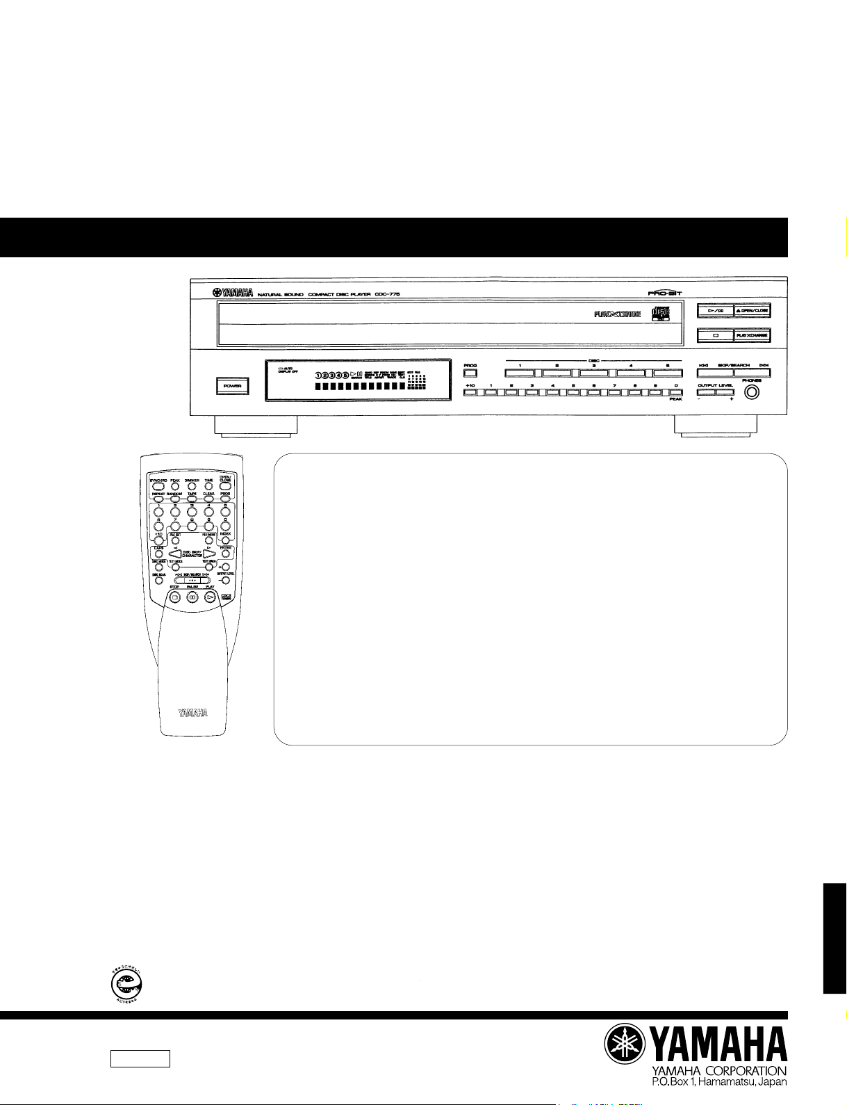
COMPACT DISC PLAYER
CDC-775
SERVICE MANUAL
SERVICE MANUAL
This manual has been provided for the use of authorized YAMAHA Retailers and their service personnel.
It has been assumed that basic service procedures inherent to the industry, and more specifically YAMAHA Products, are
already known and understood by the users, and have therefore not been restated.
WARNING: Failure to follow appropriate service and safety procedures when servicing this product may result in
IMPORTANT: The presentation or sale of this manual to any individual or firm does not constitute authorization,
The data provided is believed to be accurate and applicable to the unit(s) indicated on the cover. The research, engineering,
and service departments of YAMAHA are continually striving to improve YAMAHA products. Modifications are, therefore,
inevitable and specifications are subject to change without notice or obligation to retrofit. Should any discrepancy appear to
exist, please contact the distributor's Service Division.
WARNING: Static discharges can destroy expensive components. Discharge any static electricity your body may have
IMPORTANT: Turn the unit OFF during disassembly and part replacement. Recheck all work before you apply power to
personal injury, destruction of expensive components, and failure of the product to perform as specified.
For these reasons, we advise all YAMAHA product owners that any service required should be performed
by an authorized YAMAHA Retailer or the appointed service representative.
certification or recognition of any applicable technical capabilities, or establish a principle-agent
relationship of any form.
accumulated by grounding yourself to the ground buss in the unit (heavy gauge black wires connect to this
buss).
the unit.
■ CONTENTS
TO SERVICE PERSONNEL .....................................1~2
REAR PANELS ............................................................. 3
SPECIFICATIONS .........................................................4
INTERNAL VIEW .......................................................... 4
DISASSEMBLY PROCEDURES ..............................5~6
STANDARD OPERATION CHART ..........................7~8
TEST MODE ............................................................9~11
ADJUSTMENT.............................................................12
ERROR MESSAGES ............................................13~15
IC DATA ................................................................16~20
IMPORTANT NOTICE
DISPLAY DATA ..........................................................21
IC BLOCKS ........................................................... 22~23
PIN CONNECTION DIAGRAM ...................................23
BLOCK DIAGRAM ................................................24~25
PRINTED CIRCUIT BOARD ................................. 26~31
SCHEMATIC DIAGRAM .............................................32
PARTS LIST .......................................................... 33~42
GREASE APPLICATION DIAGRAM.......................... 43
REMOTE CONTROL TRANSMITTER........................44
CDC-775
このサービスマニュアルは、エコマーク認定の再生紙を使用しています
ThisServiceManualusesrecycledpaper.
100669

CDC-775
■ TO SERVICE PERSONNEL
1. Critical Components Information.
Components having special characteristics are marked and
must be replaced with parts having specifications equal to
those originally installed.
WALL
OUTLET
EQUIPMENT
UNDER TEST
AC LEAKAGE
TESTER OR
EQUIVALENT
<
2. Leakage Current Measurement (For 120V Models Only).
When service has been completed, it is imperative to verify
that all exposed conductive surfaces are properly insulated
from supply circuits.
● Meter impedance should be equivalent to 1500 ohm shunted
by 0.15µF.
● Leakage current must not exceed 0.5mA.
● Be sure to test for leakage with the AC plug in both
polarities.
INSULATING
TABLE
CAUTION: USE OF CONTROLS OR ADJUSTMENTS OR PERFORMANCE OF PROCEDURES OTHER THAN THOSE
SPECIFIED HEREIN MAY RESULT IN HAZARDOUS RADIATION EXPOSURE.
THE COMPACT DISC PLAYER SHOULD NOT BE ADJUSTED OR REPAIRED BY ANYONE EXCEPT PROPERLY
QUALIFIED SERVICE PERSONNEL.
PROTECTION OF EYES FROM LASER BEAM DURING SERVICING
This set employs a laser. Therefore, be sure to carefully
follow the instructions below when servicing .
1. Laser Diode Properties
● Material : GaAlAs
● Wavelength : 780 nm
● Emission Duration : Continuous
● Laser Output : max. 44.6 µW*
2. When checking the laser diode emission, keep your
eyes more than 30 cm away from the objective lens.
* This output is the value measured at a distance
of about 200 mm from the objective lens
surface on the Optical Pick-up Block.
WARNING: CHEMICAL CONTENT NOTICE!
The solder used in the production of this product contains LEAD. In addition, other electrical/electronic
and/or plastic (where applicable) components may also contain traces of chemicals found by the
California Health and Welfare Agency (and possibly other entities) to cause cancer and/or birth defects
or other reproductive harm.
DO NOT PLACE SOLDER, ELECTRICAL/ELECTRONIC OR PLASTIC COMPONENTS IN YOUR MOUTH
FOR ANY REASON WHATSOEVER!
Avoid prolonged, unprotected contact between solder and your skin! When soldering, do not inhale
solder fumes or expose eyes to solder/flux vapor!
If you come in contact with solder or components located inside the enclosure of this product, wash
your hands before handling food.
CDC-775
1
English
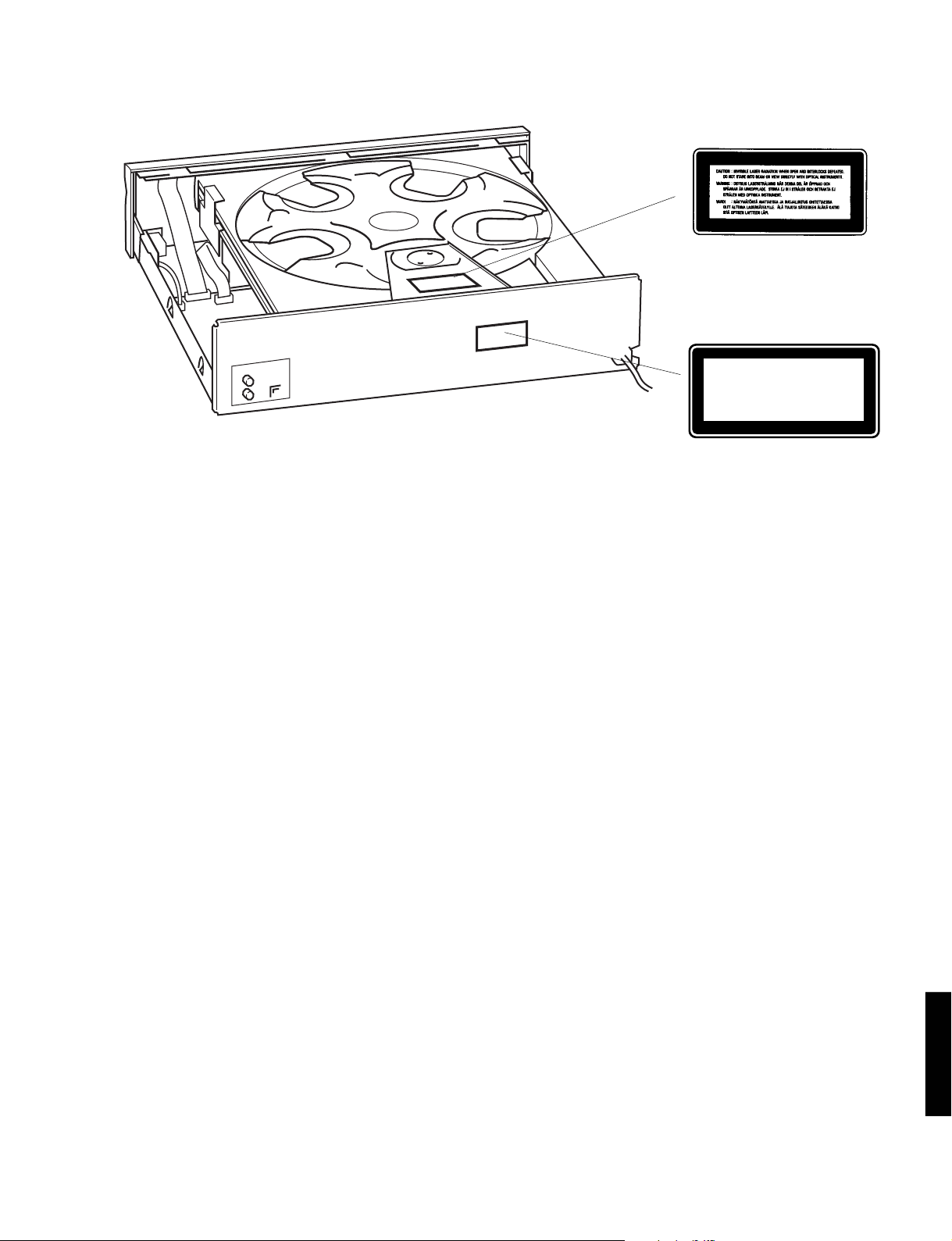
CDC-775
w R, G models
q R, G models
CLASS 1 LASER PRODUCT
➀
THIS PRINTING (SEE POSITION SHOWN IN THE ILLUSTRATION) INFORMS THE USER THAT THE APPARATUS
CONTAINS A LASER COMPONENT.
➁ THIS LABEL (SEE POSITION SHOWN IN THE ILLUSTRATION) WARNS THAT ANY FURTHER PROCEDURE WILL
BRING THE USER INTO EXPOSURE WITH THE LASER BEAM.
CAUTION : USE OF CONTROLS, ADJUSTMENTS OR PERFORMANCE OF PROCEDURES OTHER THAN THOSE
SPECIFIED HEREIN, MAY RESULT IN HAZARDOUS RADIATION EXPOSURE.
Swedish
➀
DENNA MÄRKNING (SE FIGUR) UPPLYSER OM ATT DET I APPARATEN INGÅR EN LASERKOMPONENT AV
TYP KLASS 1.
➁ VARNINGSMÄRKNING (SE FIGUR) FÖR STRÅLNING. INGREPP I APPARATEN BÖR ENDAST FÖRETAGAS AV
FACKMAN MED KÅNNEDOM OM LASER. APPARATEN INNEHÅLLER EN LASERKOMPONENT SOM AVGER
STRÅLNING ÖVERSTIGANDE GRÄNSEN FÖR LASERKLASS 1.
VARNING : OSYNLIG LASERSTRÅLNING NÄR DENNA DEL ÄR ÖPPNAD : BETRAKTA EJ STRÅLEN.
Danish
➀
DETTE MÆRKAT ER ANBRAGT SOM VIST I ILLUSTRATIONEN FOR AT ADVARE BRUGEREN OM AT APPARATET INDEHOLDER EN LASERKOMPONENT.
➁ DETTE MÆRKAT OM LASEREN ER ANBRAGT PÅ APPARATET SOM EN OPLYSNING OM AT APPARATET
INDEHOLDER ET LASERKOMPONENT.
ADVARSEL : INDGREB BOR KUN FORETAGES AF EN FAGMAND DA DER ER RISIKO FOR RADIOAKTIV
STRÅLING.
ADVARSEL : USYNLIG LASERSTRÅLING VED ÅBNING.
UNDGÅ UDSAETTELSE FOR STRÅLING.
Finnish
VARO! :
AVATTAESSA OLET ALTTIINA NÄKYMÄTTÖMÄLLE LASERSÄTEILYLLE. ÄLÄ KATSO SÄTEESEEN.
CDC-775
2
CDC-775
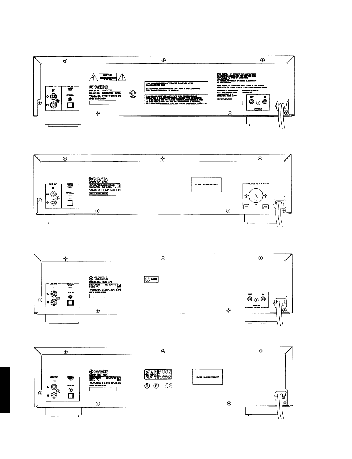
■ REAR PANELS
▼ U, C models
▼ R model
▼ A model
▼ G model
CDC-775
3

CDC-775
1
2
5
43
■ SPECIFICATIONS
■ AUDIO SECTION
Output Voltage 2.0±0.5V
S/N Ratio 115dB
Dynamic Range 100dB
Harmonic Distortion+Noise (1kHz) 0.0025%
Frequency Response (2Hz~20kHz) ±0.5dB
Headphone Output
150Ω, 1kHz, –20dB Input 200±40mV
■ GENERAL
Power Requirements
U, C models 120V AC 60Hz
G model 230V AC 50Hz
A model 240V AC 50Hz
R model 110/120/220/240V AC 50/60Hz
Power Consumption 20W
Dimensions (W x H x D) 435 x 116 x 404 mm
(17-1/8” x 4-9/16” x 15-7/8”)
Weight 5.8kg (12 lbs 12 oz)
Accessories Pin plug cord
Remote control transmitter
Dry-cell: x2 (Size “AA”, R06)
* Specifications subject to change without notice.
■ INTERNAL VIEW
q P.C.B. MAIN (2)
w CLAMP ASS’Y
e CM-210 UNIT
r P.C.B. MAIN (1)
t TRAY ASS’Y
U ........USA model
C ........Canadian model
A ........Australian model
● DIMENSION
435 (17-1/8")
G ........European model
R ........General model
6
(1/4")
394
(15-1/2")
4
(3/16")
100
(3-15/16")
16
(5/8")
Unit : mm (inch)
404
116
(15-7/8")
(4-9/16")
CAUTION FOR
TRANSPORTING THIS UNIT
When transporting this unit, first remove
all discs from the disc tray and close the
tray by pressing the OPEN/CLOSE button, and then switch off the power after
you confirm that the display has turned
as follows.
4
32
Never switch off the power if the display
does not turn as above, otherwise the
unit will get out of order during transport
because the internal mechanism is not
locked.
5
CDC-775
4
CDC-775
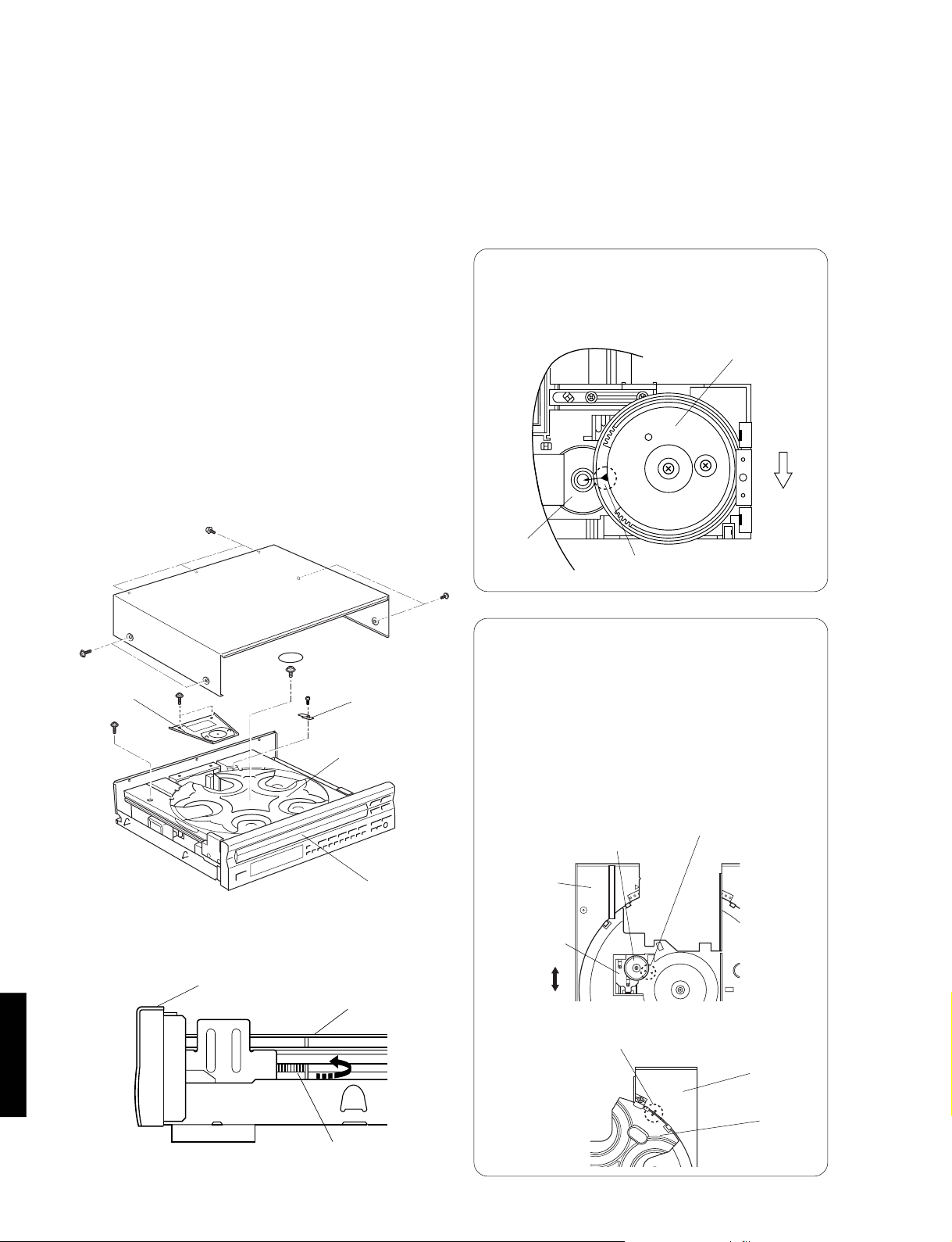
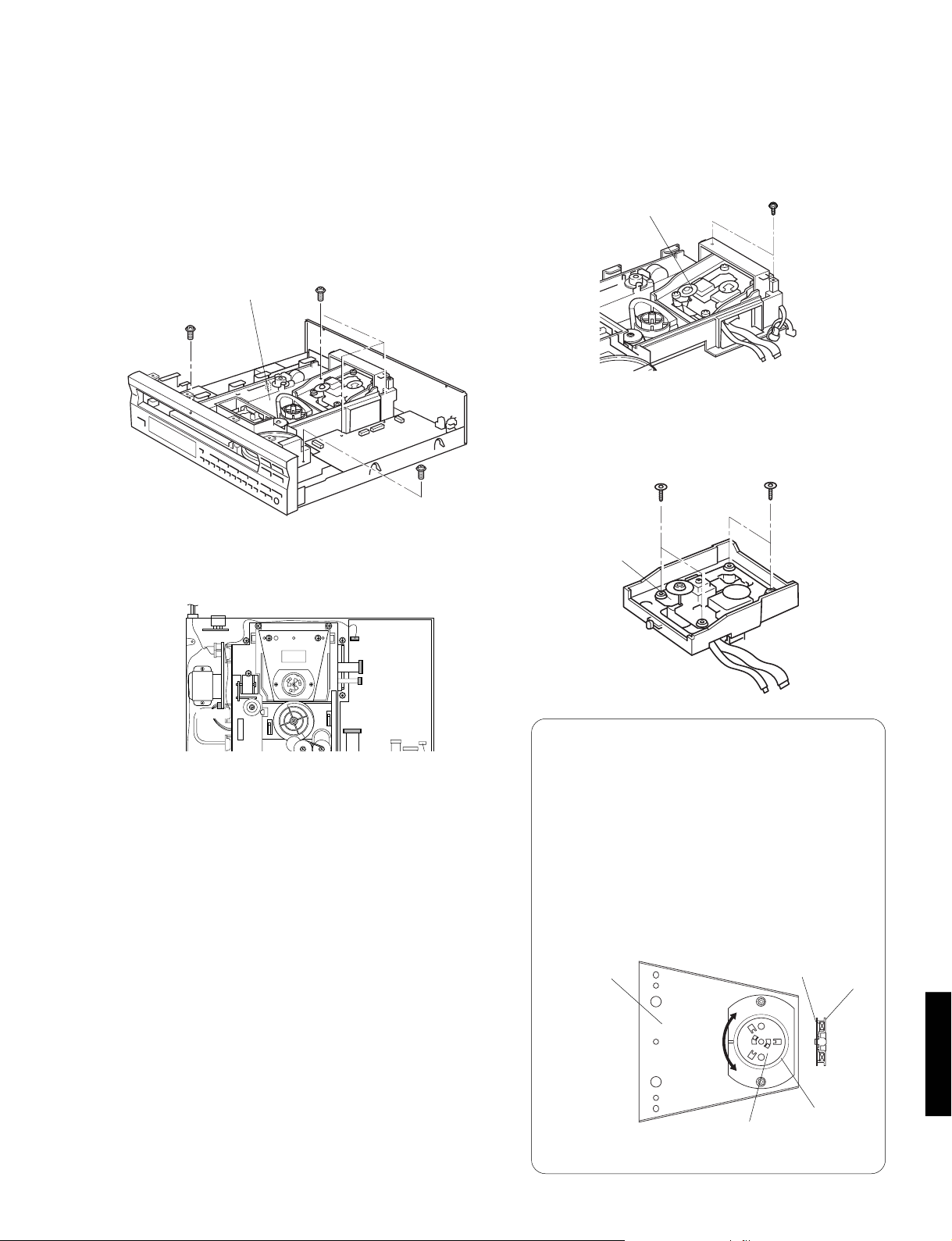
■ DISASSEMBLY PROCEDURES (Remove parts in the order as numbered.)
1. Removal of Top Cover
a. Remove 4 screws ( q ) and also 3 screws ( w ) as
shown in Fig. 1.
2. Removal of Clamp Ass’y
a. Remove 2 screws ( e ) as shown in Fig. 1.
3. Removal of Tray Ass'y
a. Remove 1 screw ( r ) as shown in Fig. 1.
b. Turn Gear/L0 as shown in Fig. 2 counter clockwise
gradually till immediately before the tray starts to
move and stop it there.
CAUTION : Gear/L0, if turned counter clockwise con-
tinuously, will mesh with the gear of the
tray and the tray will come out. When removing the tray, use care so that Gear/L0
will not mesh with the gear of the tray.
c. Pull out the Tray Ass'y.
w
Top Cover
4. Removal of Table
a. Remove 1 screw ( t ) and then remove the Support/
T as shown in Fig. 1.
b. Remove the Plate/Table as shown in Fig. 1.
c. Remove 1 screw ( y
shown in Fig. 1.
● Precaution for installation of the Tray Ass'y.
On Tray Ass'y setting.
Check the Direction of marking “▲” on gear
according to this drawing.
Gear/L01
q
) and then take off the Table as
Gear/L0
Marking
Front Panel
Fig. A
q
Clamp Ass'y
r
CDC-775
e
Front Panel
y
Plate/Table
t
Table
Tray
Support/T
Tray
Fig. 1
IMPORTANT : Installation of Table.
Install the table according to the following procedure.
1) Slide the Lever so that the Gear/RT1 becomes free. (Fig.B-1)
2) With the “▲” mark on the Gear/RT1 aligned
with the same mark on the Tray, lock it with
the Lever. (Fig.B-1)
3) Install the Table by aligning it to the thick line
/ ” mark. (Fig.B-2)
on “
*Check that the Table is locked after installation.
Fit the Gear/RT1 to “▲” mark.
Gear/RT1
Tray
Lever
Lock
Unlock
Fit the table to the thick line on “
/ ” mark.
Fig. B-1
Tray
Table
Gear/L0
Fig. 2
Fig. B-2
5
CDC-775
5. Removal of CM-210 Unit
a. Remove 5 screws ( u ) as shown in Fig. 3.
b. Remove connectors (CB201 & 202) and cables (CB1
& 2, CB300) from the P.C.B. Main.
c. Take the CM-210 Unit out slowly as shown in Fig. 3.
u
CM-210 Unit
u
u
Fig. 3
6. Removal of PU Mechanism Unit
a. Remove 2 screws ( i ) and then remove the PU
Unit Ass'y as shown Fig. 4.
i
PU Unit Ass'y
Fig. 4
b. Pull out 4 Pins ( o ) and then remove the PU
Mechanism Unit as shown in Fig. 5.
o
PU Mechanism
Unit
o
CB202
CB300
CB201
CB1
CB2
Fig. 5
● Operation Check Procedure
q Disassembly
1) Remove the top cover.
2) Remove the Clamp Ass'y.
3) Remove the stabilizer from the Holder.
Turn the Plate clockwise by 30° while holding
the Stabilizer, and the Plate will come off.
Remove the Stabilizer from the Holder.
w Clamp the disc by using the stabilizer.
e Set to the TEST mode and check for any
faulty conditions.
Frame/Clamper
Unlock
Lock
Plate
Stabilizer
CDC-775
Plate
Holder
Fig. C
6
CDC-775
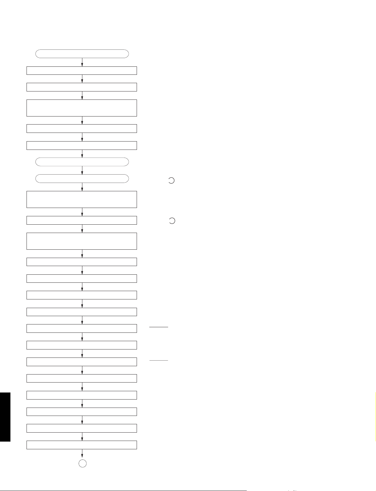
■ STANDARD OPERATION CHART
Press OPEN/CLOSE key.
Forced feed return operation.
Clamp down operation.
Disc table reset.
Tray open.
Tracking Of fset auto ADJ.
Focus Offset auto ADJ .
Load a disc in “DISC 1”.
Press PLAY ke y or push the tray.
Tray closed.
T ab le rotate.
Disc research.
“OPEN” appears on the display.
“TRV” signal is output until detection of LIMIT switch.
Proceeds to next step after detection of CLAMP switch. (SW400)
Stop after detection of LOADING switch. (SW401)
“DISC” flash.
Proceeds to next step after detection of LOADING switch. (SW401)
DISC “1” is turned to DM clamp position.
“DISC” from flashing to lighting.
Disc mechanism unit clamped up.
Feed inward switch research.
Laser ON.
Disc scan.
FOCUS Gain rough ADJ .
FOCUS Search operation.
FOCUS LOCK servo ON.
Spindle motor accelerated.
TRACKING servo ON.
Disc servo ON
VCO lock.
Tracking Gain rough ADJ .
Proceeds to next step after detection of CLAMP switch (SW401)
if FLSW = L (IC301, pin 21) Proceed to next step.
LSON = “H” (IC1, pin 3)
FLOCK = “H” → “L” (IC301, pin 8)
TLOCK = “H” → “L” (IC301, pin 7)
CDC-775
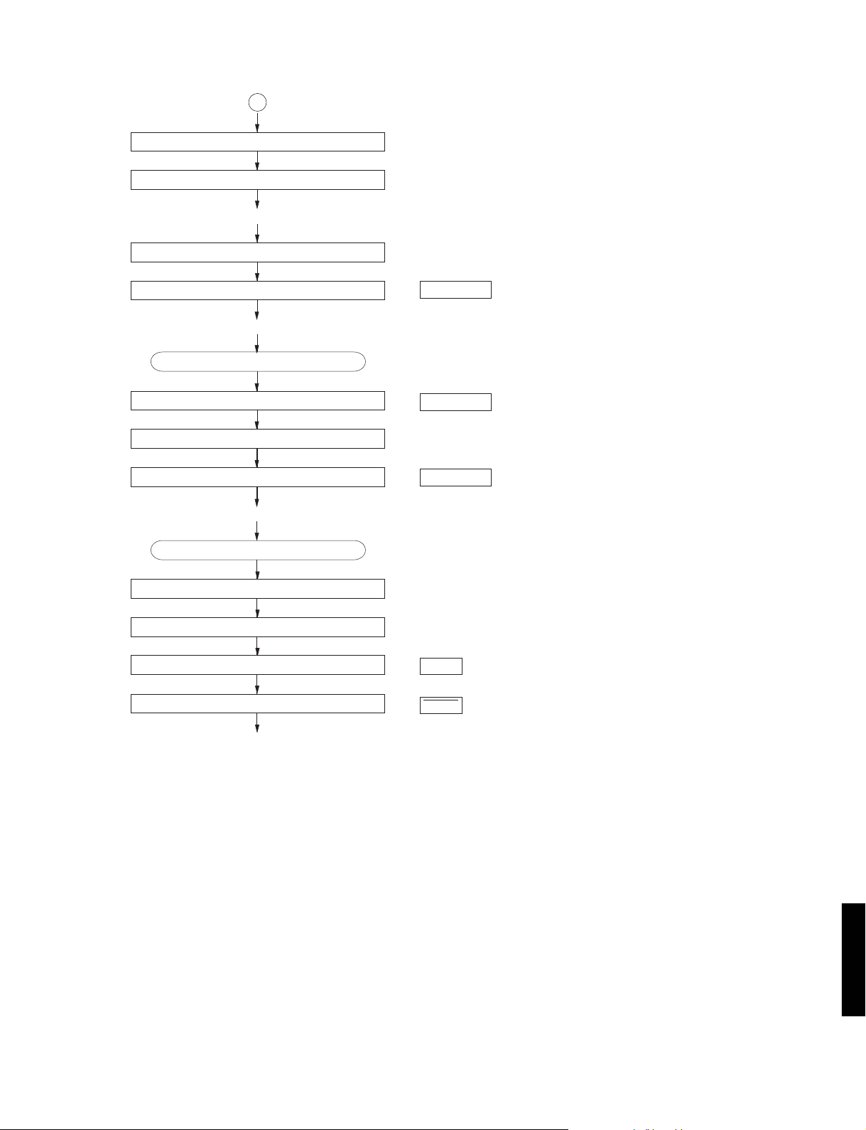
Tracking Balance ADJ. (only Tra y OPEN/CLOSE)
7
FOCUS BALANCE ADJ .
A
A
FOCUS GAIN ADJ .
TRACKING GAIN ADJ.
CDC-775
*TOC READ
After searching the beginning, MUTE is cancelled.
Set to SEARCH by means of Y,Tkey.
After searching the beginning, MUTE is cancelled.
~ Data fetch cycle ~
*
TRACK No. “1” is searched.
~ PLA Y ~
MUTE ON.
TRACK search.
~ PLA Y ~
Press the STOP key.
MUTE ON.
Spindle motor stop.
: MUTE OFF = “L” → “H”, “0:00” appears on the display.
(IC301, pin 4)
: MUTE OFF = “H”→ “L”
: MUTE OFF = “L” → “H”, “0:00” appears on the display.
Laser OFF .
Forced feed return.
~ STOP ~
: LSON = “H” → “L” (IC1, pin 3)
: FLSW = “L” (IC301, pin 21)
CDC-775
8

CDC-775
■ TEST MODE
● Starting TEST mode
Test mode is brought about when the power is turned on while the “PLAY/PAUSE” and “STOP”
keys on the panel are simultaneously pressed and held.
When the test mode is brought about, all the displays light up for about 1 second. ("TEST" on display)
NOTE : To fully operate all test modes the remote control must be used.
● Function List of Panel keys Note: “traverse servo” means the same as “feed servo”
PANEL KEY
OPEN/CLOSE
PLAYXCHANGE
PLAY/PAUSE
STOP
TSKIP
YSKIP
DISC 1
DISC 2
DISC 3
DISC 4
DISC 5
PROG
OUTPUT LEVEL –
OUTPUT LEVEL +
+10
1
2
3
4
5
6
7 NOTE:
8 NOTE:
9
0
FUNCTION
Tray open/close.
Rotating the mode of coefficients. (Coefficient mode➝Coefficient setting➝Product mode) Pressing twice will set to the product mode.
Plays if focus servo is effective. TRON, MUTE OFF.
All stop. (Focus, spindle, feed, laser, tray, etc.) Initializes FL display.
Backward traverse move. (If inner SW turns on, traverse is stopped.)
(Coefficient set up mode : upper digit down.)
Forward traverse move.
(Coefficient set up mode : upper digit up.)
Returns to product mode. (Tray and table inoperative.)
Adjustment mode 1 (TR-offset, FO-offset, FO-rough gain adjustment)
Adjustment mode 2 (TR-balance, TR-rough gain adjustment)
Adjustment mode 3 (FO-fine gain, TR-fine gain, FO-balance adjustment)
If not clamped up, measurement the rotating time of the turn table. (Slow speed) (Note 2 :See page 11)
If clamped up, enter EQSW adjustment mode. (In adjustment mode, save EQSW value to EEPROM.)
Decelerates or stops spindle.
Output level down.
(Coefficient set up mode : address down.) (EQSW adjustment mode : value down)
Output level up.
(Coefficient set up mode : address up.) (EQSW adjustment mode : value up)
—
Returns to product mode. (tray and table inoperative.)
Adjustment mode 1 (TR-offset, FO-offset, FO-rough gain adjustment)
Adjustment mode 2 (TR-balance, TR-rough gain adjustment)
Adjustment mode 3 (FO-fine gain, TR-fine gain, FO-balance adjustment)
Turn table turns counterclockwise. (Slow speed)
Turn table turns clockwise. (Slow speed)
Turn table turns counterclockwise. (Fast speed)
Turn table turns clockwise. (Fast speed)
Backward 10 TRACK KICK-continuously
Forward 10 TRACK KICK-continuously
NOTE: When the disc table is not positioned correctly, be sure to turn the disc table one full rotation by using the DISC
SKIP key on the remote control unit before canceling the TEST mode.
CDC-775
9

CDC-775
● Function List of Remote Control Transmitter
CODE
00
01
02
04
2B
2C
07
08
0A
0B
0C
0D
10
11
12
13
14
15
16
17
18
19
1A
1B
1C
1D
1E
1F
2D
4F
50
53
55
56
57
58
MODE
OPEN/CLOSE
PLAY
TSKIP
TEXT MODE
TEXT SRCH
YSKIP
REPEAT
TIME
INDEX
PROG
CLEAR
+10
RANDOM
OUTPUT LEVEL –
OUTPUT LEVEL +
DIMMER
FILE MODE
CAPS
DISC SKIP w
DISC SKIP q
DISC SCAN
PAUSE
STOP
TAPE
SYNCHRO
KEY
Traverse stop
Tray open/close
PLAY (FOON, TRON, TVON (FEON), SPON)
Backward traverse move. (If inner SW turns on, traverse is stopped.)
(Coefficient set up mode : upper digit down)
Clamp down.
(Coefficient set up mode : lower digit down)
Clamp up.
(Coefficient set up mode : lower digit up)
Forward traverse move.
(Coefficient set up mode : upper digit up)
FOON, TROF (Enter focus search if focus servo is off.)
Checks FL display. (Note 3 : See page 11)
FOON, TROF, TVOF (FEOF) (Enter focus search if focus servo is off.)
Rotates or accelerates spindle.
Decelerates spindle.
0
1
2
3
4
5
6
7
8
9
Backward 150 TRACK KICK continuously
Returns to product mode. (Tray and Table inoperative.)
Adjustment mode 1 (TR-offset, FO-off set, FO-rough gain adjustment)
Adjustment mode 2 (TR-balance, TR-rough gain adjustment)
Adjustment mode 3 (FO-fine gain, TR-fine gain, FO-balance adjustment)
Forward 1 TRACK KICK continuously
Backward 1 TRACK KICK continuously
Forward 30 TRACK KICK continuously
Backward 30 TRACK KICK continuously
Forward 150 TRACK KICK continuously
Enter coefficient set up mode.
SPON (Spindle servo on.)
Output level down.
(Coefficient set up mode : address down.) (EQSW adjustment mode : value down)
Output level up.
(Coefficient set up mode : address up.) (EQSW adjustment mode : value up)
Checks FL display. (Note 3 :See page 11)
Note :Don't use
Switches servo gain (normal or High). Head amp (GCTRL)
DISC SKIP + (Clockwise)
DISC SKIP – (Counterclockwise)
Measurement the rotating time of the turn table. (Fast speed) (Note 2 :See page 11)
FOON, TROF, TVOF (FEOF) (Enter focus search if focus servo is off.)
All stop. (Focus, spindle, traverse, laser, tray, etc.)
Spindle free (off)
Backward traverse move
CUSTOM CODE = (79)x
FUNCTION
CDC-775
10
CDC-775
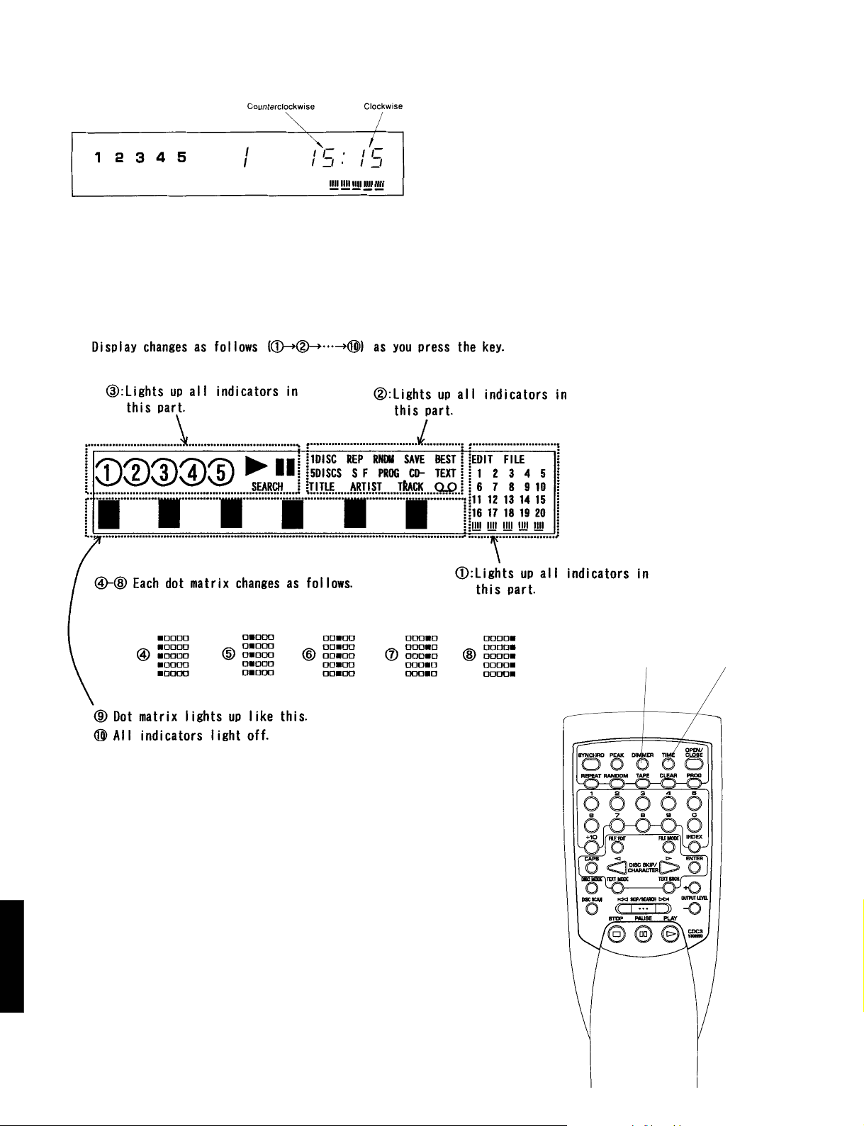
(Note 2) Display at time measurement.
The time display shows the time for 1 rotation of the turn table.
The unit of time is 0.1 second (rotate fast) or 1 second (rotate slow).
(Note 3) Checks FL display.
CDC-775
DIMMER
TIME
11
■ ADJUSTMENTS
EFM(J180)
GND(J44)
CDC-775
● Necessary items
Measuring instruments
Oscilloscope : x 1
(Band width of 50MHz or more)
Jitter meter : x 1
Test disc
SONY YEDS-18 (P/No. TX911730),
A-BEX TCD-782 (P/No. TX913350)
or Philips 5 : x 1
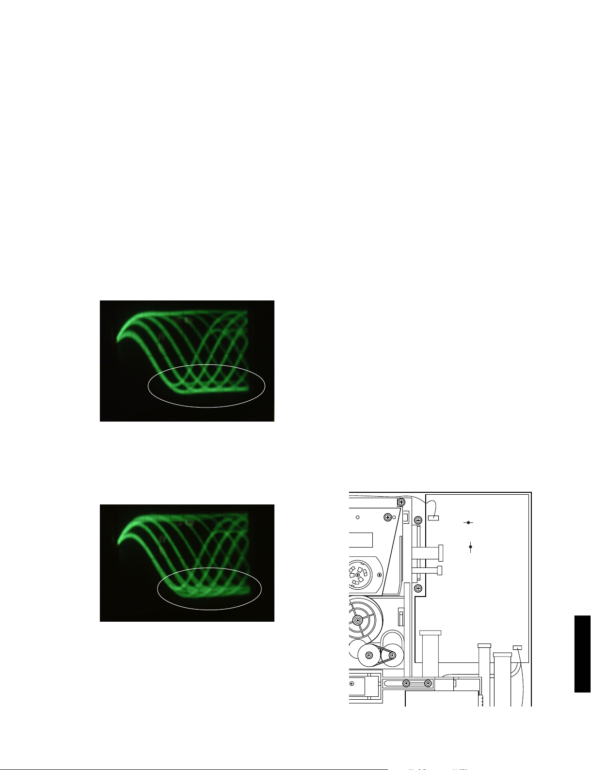
OK (Fig. A)
● Jitter Adjustment
q Connect an oscilloscope and a jitter meter to the test
points EFM and GND.
w Set to the TEST mode.
(While pressing both the “PLAY/PAUSE” and “STOP”
keys, turn ON the power switch.) See page 9 for
TEST mode explanation.
e Set the test disc on the turntable, and press the
“TEXT SRCH” key on the remote control. And then
the disc is clamped up.
r Press the DISC2 key.
(Auto adjustment mode 1)
t Press the DISC3 key.
(Auto adjustment mode 2)
y Press the DISC4 key.
(Auto adjustment mode 3)
u Press the PLAY/PAUSE key.
(Play mode)
i Press the DISC5 key, and check “EQSW ADJ (DC)”
is displayed.
(EQSW adjustment mode)
o Press the OUTPUT LEVEL + or – key, and adjust the
needle of jitter meter to minimum.
Specification : ≤ 32 nS (3T)
V : 0.2V/div H : 0.5µsec/div
AC range 1 : 1 probe
NG (Fig. B)
Bottom
Bottom
!0 Press the OUTPUT LEVEL + or – key, and adjust the
bottom of EFM signal (eye pattern) waveform clearly.
(Fig. A)
!1 At last press the DISC5 key, and check “00:00”(time)
is displayed.
CDC-775
12
 Loading...