

Page 1
Command Link Plus
Multifunction
Color Gauge
OWNER’S MANUAL
Read this manual carefully before using the
Command Link Plus Multifunction Color Gauge.
U.S.A.Edition
LIT-18626-09-13
6Y9-2819U-E0
Page 2

Read this manual carefully before using the Comman d Link Plus Multifu nction Color
Gauge. Keep this manual onbo ard in a waterproof bag when boating. This manual
should stay with the Command Link Plus Multifunction Color Gauge if it is sold.
Page 3
Important manual information
To the owner
Thank you for selecting the Command Link Plus Multifunction Color Gauge (hereinafter
called the Multi-Display). This Owner's Manual contains information needed for proper operation. A thorough understanding of these simple instructions wi ll help you obta in maximum
enjoyment from your new Yamaha. If you have any question about the operation of the MultiDisplay, please consult a Yamaha dealer.
In this Owner's Manual particularly important information is distin guished in the following
ways.
This is the safety alert symbol. It is used to alert you to potential personal injury hazards.
Obey all safety messages that follow this symbol to avoid possible injury or death.
WARNING
A WARNING indicates a hazardous situation which, if not avo ided, could result in
death or serious injury.
NOTICE
A NOTICE indicates special precautions that must be taken to avoid damage to the
outboard motor or other property.
TIP:
A TIP provides key information to make procedures easier or clearer.
Information about the owner's manual
Yamaha continually seeks advancements in product design and quality. Therefore, while this
manual contains the most current product information available at the time of printing, there
may be minor discrepancies between your machine and this manual.
Command Link Plus Multifunction Color Gauge
OWNER'S MANUAL
©2010 by Yamaha Motor Corporation, U.S.A.
2nd Edition, March 2010
All rights reserved.
Any reprinting or unauthorized use without the
written permission of Yamaha Motor Corporation,
U.S.A. is expressly prohibited.
Printed in Japan
P/N LIT-18626-09-13
Page 4
Safety information
Safety information
The Multi-Display will notify the operator when eng ine abnormalities occur by displaying a
pop-up window and alert icons. A pop-up window will also be displayed when specific alert
conditions occur.
When events requiring multiple pop-up windows occur, the pop-up wind ow with the highest
priority is displayed first. Press the “SET” button to display pop-up windows in order of priority.
There are 3 types of pop-up windows, “Alert Notifications,” “Maintenance Notifications,” and
“Other Notifications,” each displayed with its own color.
Alert Notifications: Red
Maintenance Notifications: Yellow
Other Notifications: Sky blue
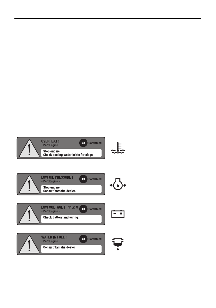
Alert Notifications
Follow the following instructions for responding to each specific alert. For further information,
see page 11.
Overheat alert
Displayed when the engine temperature rises too high. Stop the
engine and check the cooling
water inlet.
Low oil pressure alert
Displayed when the oil pressure
drops too low. Stop the engine
and consult a Yamaha dealer.
Low battery voltage alert
Displayed when the battery voltage drops too low. Check the
battery and battery connections.
Water in fuel alert
Displayed when water has accumulated in the water separator
(fuel filter). Consult a Yamaha
dealer.
Page 5
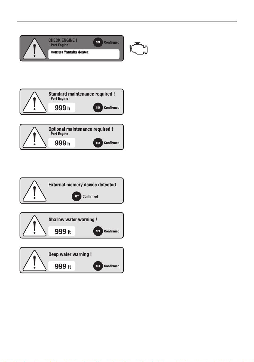
Maintenance Notifications
Other Notifications
Safety information
Engine trouble alert
Displayed when the engine malfunctions. Consult a Yamaha
dealer.
Displayed when scheduled maintenance is
overdue.
Carry out the maintenance and reset the
maintenance schedule.
You can also specify individual maintenance intervals. For further information,
see page 20.
Displayed when an external memory (USB
memory) is connected.
Displayed when water depth falls below a
preset threshold. For further information,
see page 6.
Displayed when water depth exceeds a
preset threshold. For further information,
see page 6.
Page 6
List of abbreviations
List of abbreviations
The following are abbreviations displayed on this meter or used in this manual.
Abbreviation Description
ABYC American Boat and Yacht Council
AVAL Available fuel
CL Command Link
C PORT Center Port side
C STBD Center Starboard side
ECO, ECON Fuel Economy
Eng Engine
EUR Europe
Ex. Exhaust
FForward
FW Fresh Water tank
GNRTR, GT Generator fuel tank
GPS Global Positioning System
INT Intake
LAN Local Area Network
Mfg./Dlr. Manufacturer/Dealer
N Neutral
NMEA National Marine Electronics Association
No. Number
Num. Number
OPT Optional
R Reverse
R/C Remote Control
STATS Status
STD Standard
SYNC Synchronization
Temp Temperature
TFT Thin Film Transistor
USB Universal Serial Bus
WASTE, WS Waste Water tank
Page 7
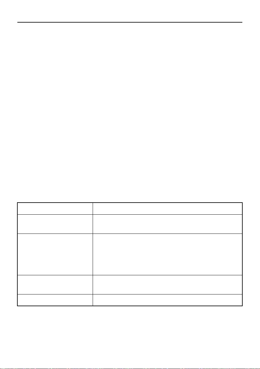
Table of contents/Specifications
Table of contents
Specifications.........................................................................1
Names and functions of parts................ ... ... .... ... ..................2
Initialization ............................................................................3
Meter display..........................................................................7
Main screens.......................................................................7
Alert display ..................... .... ... ... ... ....................................11
Condition display...............................................................12
Basic display.............. .......................................................13
Specific selection ..............................................................15
Meter operation ....................................................................17
Switching the meter display ..............................................17
Menu screen.........................................................................19
Operating the menu screen ....... ... ....................................19
Menu items and functions.................................................20
Adjusting trolling engine speed .........................................25
Trouble codes.......................................................................27
Specifications
Field Specification
Power source Rated voltage: 12 V
Operating voltage range: 8–16 V
Communications specification
Other interfaces Fuel sensor interface x 4
Display 5-inch color TFT
Information system LAN interface:
The Multi-Display conforms to J1939-based Yamaha Network specifications.
GPS Interface:
The Multi-Display conforms to NMEA0183.
USB interface (Ver.1.1, 2.0) x 1
1
Page 8
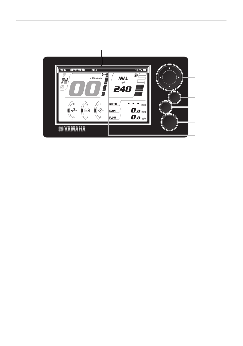
Names and functions of parts
Names and functions of parts
1
2
SET
CANCEL
MENU
3
4
5
6
Name Explanation of function
1 Display Displays engine information, boat/environment information,
setting menus, and so on.
2 Directional keypad “LI” (Up/Down) buttons
• Switches main screen
• Moves cursor (selects) on the menu screen
• Adjusts engine speed during trolling
“HJ” (Left/Right) buttons
• Switches main screen
• Moves cursor (selects) on the menu screen
3 “SET” button • Set
• Moves the menu screen cursor to the right
• When on the main screen, mov es to the “BRIGHTNESS” screen
4 “CANCEL” button • Cancel
• Moves from any setting screen to the menu screen
• Moves from the menu screen to the main screen
• Moves the menu screen cursor to the left
• Cancels trolling mode
• When on the main screen, moves to the “TRIP” screen
5 “MENU” button • Moves from any screen to the top menu screen
6 Status bar Displays the time and nam e of the main screen selected.
Time will not be displayed if time information is not received
from the network.
2
Page 9
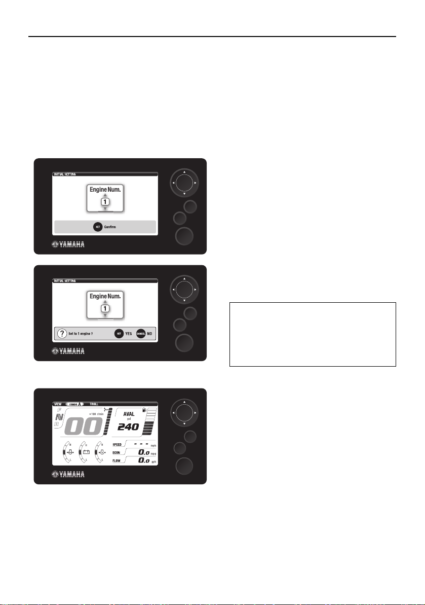
Initialization
Initialization
The initialization screen is not normally displayed, except during installation.
TIP:
If it does appear, consult a Yamaha dealer.
Configuring the number of outboard motors
1. Turn the engine switch to “ON.” The
initialization screen is displayed.
SET
CANCEL
MENU
2. Use “LI” (Up/Down) buttons on the
directional keypad to select the number
of outboard motors on your boat.
CANCEL
CANCEL
SET
1: Single-engine type
2: Twin-engine type
MENU
3: Triple-engine type
4P: Quadruple-engine type (PORT side)
4S: Quadruple-engine type (STBD side)
3. Set using the “SET” button.
4. The main screen is displayed.
SET
MENU
3
Page 10
Initialization
Fiel
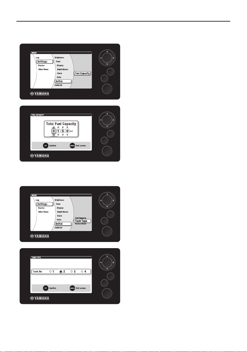
Configuring fuel tank parameters
1. Use the directional keypad and the
“SET” button to display the “Fuel
Capacity” in the menu screen.
Fiel capacity
capacity
Tank Type
Factory Reset
Configuring the tank sensors
SET
CANCEL
MENU
2. Use the directional keypad to configure
the total fuel capacity on your boat.
3. Set using the “SET” button.
SET
CANCEL
MENU
1. Use the directional keypad and the
“SET” button to display the “Tank
Type” in the menu screen.
SET
CANCEL
MENU
2. Use the “HJ” (Left/Right) buttons on
the directional keypad to select the
“Tank No.”
SET
CANCEL
MENU
4
3. Set using the “SET” button.
Page 11
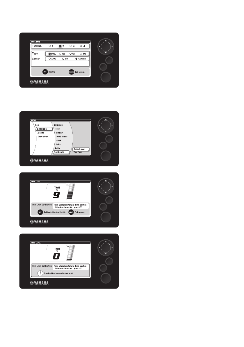
Initializing trim angle
CANCEL
CANCEL
Initialization
4. Use the directional keypad to select
the sensor from the “Sensor” list.
5. Set using the “SET” button.
SET
MENU
1. Fully trim the outboard motor down.
2. Use the directional keypad and the
“SET” button to display the “Trim
SET
MENU
Level” in the menu screen.
3. Check that the value displayed on the
screen shows “0 %.”
CANCEL
CANCEL
SET
MENU
4. Use the “SET” button to reset the value
if any value other than “0 %” is displayed.
SET
MENU
5
Page 12

Initialization
Configuring the depth alarm
NOTICE
Make sure to configure water depth b e fore turning on the depth alarm.
1. Use the directional keypad and the
“SET” button to display the “Depth
Alarms” in the menu screen.
SET
CANCEL
MENU
2. Use the directional keypad and the
“SET” button to select “Threshold Setting.”
SET
CANCEL
MENU
3. Use the directional keypad to configure
the water depth.
4. Set using the “SET” button.
SET
CANCEL
MENU
6
NOTICE
Make sure to press the “SET” button to
complete the setting.
Page 13

Meter display
Meter display
Main screens
The layouts of main screen differ depending on the number of outboard motors on your boat.
Display can be switched between digital and analog displays.
Single-engine type
Twin-, Triple-, Quadruple-engine types
Number of outboard
motors
Single-engine type COMBO/TROLL
Twin-, Triple-, Quadruple-
engine types
COMBO: Displays engine information and boat/environment information.
ENGINE: Displays engine information.
BOAT STATS: Displays boat/environment information.
TROLL: Adjusts the trolling engine speed. For further information, see page
25.
COMBO/ENGINE/BOAT STATS/TROLL
Main screen
7
Page 14

Meter display
■ COMBO
Single-engine type Twin-, Quadruple-engine type
2
3
1
4
Triple-engine type Analog display
3
1
4
2
2
2
3
3
1
4
1: Alert display area
2: Condition display area
3: Basic display area
4: Specific selection area
1
4
8
Page 15

■ ENGINE
Twin-, Quadruple-engine types Triple-engine type
2
3
2
Meter display
3
1
4
Analog display
2
3
1
4
1: Alert display area
2: Condition display area
3: Basic display area
4: Specific selection area
1
4
9
Page 16

Meter display
■ BOAT STATS
Digital display Analog display
■ TROLL
Single-engine type Twin-, Quadruple-engine types
T r ip le-eng ine typ e
10
Page 17

Meter display
Alert display
Red-colored alert indicators will be displayed in the alert display area for “Overheat ale rt,”
“Low oil pressure alert,” “Low battery voltage alert,” “Water in fuel alert,” and “Engine trouble
alert.”
Overheat alert
NOTICE
Do not operate the outboard motor when the overheat alert is
displayed. Otherwise, severe engine damage could result.
Blinks when the engine temperature rises too high.
If the overheat alert blinks, stop the engine and check that the cooling water inlet on the lower case is not blocked. Consult your
Yamaha dealer if the problem cannot be located and corrected.
Low oil pressure alert
NOTICE
Do not operate the outboard motor when the low oil pressure
alert is displayed. Otherwise, severe engine damage could
result.
Blinks when the oil pressure drops too low.
Stop the engine and check the engine oil level. If the oil level is below
the specified level, add engine oil up to the proper level. For further
information, see the Owner's Manual of the outboard mo tor.
Consult your Yamaha dealer if the alert continues to blink even
though the oil level is at the proper level.
Low battery voltage alert
WARNING
Do not stop the engine when the low battery voltage alert is displayed. Otherwise, the engine may not restart.
Blinks when the battery voltage drops too low.
Take the engine to a Yamaha dealer and have it checked immediately.
11
Page 18

Meter display
Water in fuel alert
NOTICE
Water in fuel can cause engine malfunction.
Blinks when water has accumulated in the water separator (fuel filter)
during cruising.
Stop the engine and drain the water from the water separator (fuel filter). For further information, see the Owner's Manual of the outboard
motor.
Engine trouble alert
NOTICE
Engine is not controlled properly. Consult a Yamaha dealer.
Blinks when the engine malfunctions.
Take the engine to a Yamaha dealer and have it checked immediately.
Condition display
Orange signals are displayed in the condition display area for “Engine warming up,” “Engine
synchronization controlling,” and “Yamaha Security System Y-COP is locked.”
12
Displayed when the Yamaha Security System Y-COP is locked. (Not
displayed when your engine is not equipped with the Yamaha Security System Y-COP.)
Displayed when the engine is warming up. Goes off when engine
warm-up is finished.
Displayed when engine is under synchronization controlling. Goes
off when synchronization controlling is deactivated.
(Not displayed for single- and quadruple-engine types.)
Page 19

Meter display
Basic display
“Shift position,” “Tachometer,” and “Trim angle” are displayed in the basic display area.
Single-engine type
23
1
Twin-engine type
231
T r ip le-eng ine typ e
231
23
1
23
1
23
1: Shift position area
2: Tachometer area
3: Trim angle area
1
13
Page 20

Meter display
Quadruple-engine type
231
1: Shift position area
2: Tachometer area
3: Trim angle area
23
1
14
Page 21

Meter display
Specific selection
You can select the following meter displays for display in the specific selection area. You can
combine the displayed meters and register up to 4 different types of settings.
■ Engine information
Cooling water
temperature
Cooling water
pressure (with
scale)
Battery voltage 1 Accessory bat-
Battery voltage 2 Accessory bat-
■ Boat/Environmental information
Engine oil pressure
Cooling water
pressure (without scale)
tery voltage 1
tery voltage 2
Boat speed
15
Page 22

Meter display
Fuel economy Sailing distance
Fuel consumption Total fuel flow
PORT fuel flow STBD fuel flow
CENTER fuel flow C PORT fuel flow
C STBD fuel flow PORT hour meter
STBD hour meter CENTER hour meter
C PORT hour meter C STBD hour meter
Water Depth Water temperature
Available fuel
16
Page 23

Meter operation
Meter operation
You can switch main screens to suit your preferences. Adjust the trolling engine speed from
the main screen.
Switching the meter display
■ Switching the main screen
Press the “HJ” (Left/Right) buttons on the directional keypad to switch the main screen.
Single-engine type
1
Twin-, Triple-, Quadruple-engine types
1
1: The main screen currently displayed.
17
Page 24

Meter operation
■ Switching the registered screens
Press the “LI” (Up/Down) buttons on the directional keypad to select a display from 4
screen types (A, B, C, D).
Single-engine type
Twin-, Triple-, Quadruple-engine types
■ Customizing the registered screen
Use the menu screen to customize the specific selection area. For further information, see
page 21.
18
Page 25

Menu screen
Operating the menu screen
You can configure and reset the settings on the menu screen.
You can also check information recorded on the outboard motor.
1. Press the “MENU” button.
The menu screen is displayed.
SET
CANCEL
MENU
2. Use the directional keypad buttons and
the “SET” button to display the desired
menu.
SET
CANCEL
MENU
Menu screen
(
STD and OPT
3. Use the directional keypad and the
)
SET
CANCEL
MENU
“SET” button to set the applicable
fields.
4. Press the “CANCEL” button to return to
the previous menu.
Press the “CANCEL” button one more
SET
CANCEL
MENU
time to return to the main screen.
Pressing the “MENU” button will also
return you to the main screen.
19
Page 26

Menu screen
Menu items and functions
■ Logs
Trip
• Reset fuel consumption
• Reset sailing distance
• Reset designated driving time
Maintenance
• Reset time elapsed since previous
maintenance (reset time)
• Setting maintenance intervals
■ Settings
20
Brightness
• Turning on and off the backlight, and
adjusting brightness
• Changing the Multi-Display settings
individually/in a batch
• Day-night screen change
• Time settings for automatic day-night
screen change
(Day screen is always displayed even
when the automatic day-night screen
change is on, if time information is not
received.)
Page 27

Menu screen
Tone
• Adjusting button operation sounds
• Changing the Multi-Display settings
individually/in a batch
Display
Favorites
• Setting display fields for ENGINE,
BOAT STATS and COMBO screens
• Switching between digital and analog
displays (You can only switch some
displays)
Color
• Setting backgrounds and text display
colors
Mfg./Dlr. Set
• Input and output of Multi-Display setting information
• Reading/deleting designated images
for startup screen
Depth Alarms
• Water depth alarm On/Off settings
• Water depth alarm threshold setting
21
Page 28

Menu screen
Clock
• Time offset setting
Units
• Changing display units
Initial
Fuel Capacity
• Setting the total volume of the fuel
tanks connected to the Multi-Display
Tank Type
• Setting types for tanks connected to
the Multi-Display (Fuel, fresh water,
generator fuel, and sewage)
• Setting sensor type (ABYC/EUR/
YAMAHA)
Factory Reset
• Initializing the Multi-Display
• Initializing the connected Command
Link Plus Gateway
22
Page 29

■ Alarms
Menu screen
Calibrate
Trim Level
• Zero-setting the trim angle
Fuel Flow
• Adjusting the fuel consumption figure
Current
• Displays currently occurring alerts. For
further information, see pages 11 and
12.
Trouble Codes
• Displays the trouble code and name of
the alert. (Up to 5 displayed for each
engine)
TIP:
Please mention the trouble code when you
contact a Yamaha dealer. For further information, see page 27.
23
Page 30

Menu screen
■ Other Views
Tanks
• Can display the volume of any tanks.
• Each tank type is displayed in a predefined color.
Fuel tanks: Navy blue
Fresh water tanks: Blue
Sewage tank: Orange
Generator fuel tank: Green
Trim
• Displays trim angle as a percentage.
24
Page 31

Adjusting trolling engine speed
Adjusting trolling engine speed
Adjust the trolling engine speed using “TROLL” on th e main screen. You can adjust designated trolling speed in units of 50 r/min. The trolling engine speed is synchronized for all engines in a multi-engine configuration. You can switch to trolling mode when all the following
conditions are satisfied:
Conditions for changing to trolling mode
• When the engine is running.
• When the throttle lever is in the fully closed position.
• When the gear shift is in the N position.
• When “TROLL” is selected on the main screen.
1. Select “TROLL” on the main screen.
Press the “SET” button to switch to
trolling mode.
SET
CANCEL
MENU
“VIEW” on the status bar will switch to
“TROLL.”
CANCEL
CANCEL
SET
MENU
2. Set the gear shift in the F or R position,
and then use the “LI” (Up/Down) buttons of the directional keypad to adjust
SET
the designated trolling engine speed.
(The parameters within which the
engine speed can be adjusted depend
MENU
on the outboard motor.)
25
Page 32

Adjusting trolling engine speed
3. Set the gear shift in the N position, and
SET
CANCEL
then press the “CANCEL” button to
cancel the trolling mode.
“TROLL” on the status bar will switch to
“VIEW.”
MENU
TIP:
• If the throttle lever is in the fully closed
position, pressing the “CANCEL” button
will cancel the trolling mode even when
the gear shift is in the F or R position.
Howev er, if the throttle is open, pressing
“CANCEL” button will not cancel the trolling mode.
• Trolling mode will be automatically can-
celed if the trolling speed exceeds a predetemined speed for each engine.
26
Page 33

Trouble codes
Trouble codes
Trouble
code
13 Pulser Coil Pulser coil malfunction
15 Temp Sensor Water temperature sensor malfunction
19 Battery Voltage Charging system malfunction
23 Intake Temp Sensor Intake air temperature sensor malfunction
24 Cam Position Sensor Cam position sensor (EXH) malfunction
27 Water in Fuel Water in fuel
29 Intake Press Sensor Air pressure sensor (INT) malfunction
37 Intake Air Passage Intake air passage (Air leakage)
39 Oil Press Sensor Engine oil pressure sensor malfunction
44 Engine Stop Lanyard Engine shut-off switch on
46 Overheat Thermoswitch Overheat thermoswitch malfunction
71 Cam Position Sensor (STBD
INT)
72 Cam Position Sensor (PORT
INT)
73 Oil Control Valve (STBD) Oil control valve (STBD) malfunction
74 Oil Control Valve (PORT) Oil control valve (PORT) malfunction
83 Trim & Tilt Sensor Trim/tilt sensor malfunction (PTT sensor
85 ION Detection Module ION detection module malfunction
86 Immobilizer immobilizer malfunction
112-119 Electronic Throttle System Electronic throttle system malfunction
121-123 Electronic Throttle System Electronic throttle system malfunction
124-128 Throttle Position Sensor Throttle position sensor malfunction
129 Electronic Throttle System Electronic throttle system malfunction
136-139 Electronic Throttle System Electronic throttle system malfunction
141-145 Electronic Throttle System Electronic throttle system malfunction
146-150 Shift Position Sensor Shift position sensor malfunction
153-155 Shift Position Sensor Shift position sensor malfunction
156-157 Eng-R/C Communication Engine–Remote control communication
160-181 Remote Control System Remote control system malfunction (Dig-
183-184 Remote Control System Remote control system malfunction (Dig-
Item Cause
(Thermo sensor malfunction)
Cam position sensor (STBD INT) malfunction
Cam position sensor (PORT INT) malfunction
malfunction)
error
ital Electronic Control)
ital Electronic Control)
27
Page 34

Trouble codes
Trouble
code
186-187 Remote Control System Remote control system malfunction (Dig-
Item Cause
ital Electronic Control)
28
Page 35

Page 36

YAMAHA MOTOR CORPORATION, USA
Printed in Japan
March 2010 - 0.6 x 2 ABE
Printed on recycled paper
 Loading...