

Page 1

Reference Manual
How to Use This Reference Manual
The 01V96i Reference Manual (this document) allows you to
search for terms and take advantage of links in the text.
Searching for terms
To search for a term, use the search function of the software
you’re using to view this document.
If you’re using Adobe Reader, enter the term in the search box
and press the <Enter> key of your computer keyboard to
search for occurrences of that term.
Note: The latest version of Adobe Reader can be downloaded
from the following URL.
http://www.adobe.com/products/reader.html
Displaying the next/previous
view
If you’re using Adobe Reader, you can jump to the previous/
next view in your viewing history. This is a convenient way to
jump back to the previous page after you’ve used a link to
jump to a different page.
Note:
• If the Previous View / Next View buttons are not shown in the
toolbar, you can hold down your computer keyboard’s <Alt>
key and use the <←><→> keys to jump to the previous or next
view.
• For details on using other PDF-viewing software, refer to the
owner’s manual of the software you’re using.
Using the Function Tree
A function tree for the 01V96i is provided on page 4 and following. You can use this to quickly find the explanatory page
you want.
Page 2

2 Contents
Contents
How to Use This Reference Manual ............................................... 1
Contents of the Owner’s Manual (Booklet) .......... 3
Function Tree .......................................................... 4
Control Surface & Rear Panel ................................. 6
Control Surface .................................................................................. 6
Rear Panel ......................................................................................... 10
Analog I/O & Digital I/O ...................................... 12
Analog Inputs & Outputs ............................................................... 12
Digital Inputs & Outputs ................................................................ 13
Converting Sampling Rates of Signals Received at I/O Card
Inputs ................................................................................. 14
Monitoring Digital Input Channel Status .................................... 14
Dithering Digital Outputs .............................................................. 15
Setting the Transfer Format for Higher Sampling Rates ........... 16
Input Channels ...................................................... 17
About Input Channels .................................................................... 17
Setting the Input Channels from the Display .............................. 18
Setting the Input Channels from the Control Surface ............... 25
Pairing Input Channels ................................................................... 26
Naming Input Channels ................................................................. 28
Bus Outs ................................................................ 29
About Stereo Out ............................................................................. 29
Bus Out 1–8 ...................................................................................... 29
Setting the Stereo Out and Bus Out 1–8 from the Display ........ 30
Setting the Stereo Out and Bus Out 1–8 from the Control
Surface ............................................................................... 33
Pairing Buses or Aux Sends ........................................................... 33
Attenuating Output Signals ........................................................... 34
Naming the Stereo Out and Bus Outs .......................................... 35
Aux Outs ................................................................ 36
Aux Out 1–8 ..................................................................................... 36
Setting Aux Out 1–8 from the Display ......................................... 36
Setting Aux Out 1–8 from the Control Surface ........................... 38
Setting Aux Send Levels .................................................................. 38
Viewing Aux Send Settings for Multiple Channels .................... 40
Panning Aux Sends ......................................................................... 41
Copying Channel Fader Positions to Aux Sends ........................ 42
Input & Output Patching ..................................... 43
Input Patching ................................................................................. 43
Output Patching .............................................................................. 44
Patching Direct Outs ....................................................................... 46
Insert Patching ................................................................................. 47
Monitoring ............................................................ 49
Monitor ............................................................................................. 49
Monitor and Solo Setup .................................................................. 49
Using the Monitor ........................................................................... 50
Using the Solo Function ................................................................. 51
Surround Pan ........................................................ 52
About Surround Pan ....................................................................... 52
Setting Up and Selecting Surround Pan Modes .......................... 53
Surround Panning ........................................................................... 56
Grouping Channels & Linking Parameters .......... 59
Grouping & Linking ........................................................................ 59
Using Fader Groups and Mute Groups ........................................ 59
Using Fader Group Master ............................................................ 61
Using Mute Group Master ............................................................. 62
Linking EQ and Compressor Parameters .................................... 62
Internal Effects ..................................................... 64
About the Internal Effects .............................................................. 64
Using Effects Processors via Aux Sends ....................................... 64
Inserting the Internal Effects into Channels ................................ 65
Editing Effects .................................................................................. 66
About Add-On Effects .................................................................... 67
About Plug-Ins ................................................................................. 67
Scene Memories ................................................... 68
About Scene Memories ................................................................... 68
What is Stored in a Scene? .............................................................. 68
About Scene Numbers .................................................................... 68
Storing and Recalling Scenes .......................................................... 69
Auto Scene Memory Update .......................................................... 70
Fading Scenes ................................................................................... 71
Recalling Scenes Safely .................................................................... 72
Sorting Scenes ................................................................................... 72
Copying and Pasting a Scene (Global Paste) ............................... 73
Libraries ................................................................ 74
About the Libraries .......................................................................... 74
General Library Operation ............................................................. 74
Using Libraries ................................................................................. 75
Remote Control .................................................... 83
About Remote Function ................................................................. 83
Pro Tools Remote Layer ................................................................. 83
Nuendo/Cubase Remote Layer ...................................................... 93
Other DAW Remote Layer ............................................................. 94
MIDI Remote Layer ......................................................................... 94
Machine Control Function ............................................................. 98
MIDI .................................................................... 100
MIDI & the 01V96i ........................................................................ 100
MIDI Port Setup ............................................................................ 101
Assigning Scenes to Program Changes for Remote Recall ...... 103
Assigning Parameters to Control Changes for Real-time Control
Controlling Parameters by Using Parameter Changes ............. 106
Transmitting Parameter Settings via MIDI (Bulk Dump) ....... 107
Other Functions ................................................. 109
Setting Preferences ......................................................................... 109
Creating a Custom Layer by Combining Channels
(User Assignable Layer) ................................................. 110
Cascading Consoles ....................................................................... 111
Checking the Battery and the System Version .......................... 113
Calibrating the Faders ................................................................... 113
Index ................................................................... 115
Appendix: Parameter Lists .............................. 119
USER DEFINED KEYS ................................................................. 119
USER DEFINED KEYS Initial Assignments ............................. 121
Input Patch Parameters ................................................................ 121
Initial Input Patch Settings ........................................................... 123
Output Patch Parameters ............................................................. 125
Initial Output Patch Settings ........................................................ 127
User Defined Remote Layer Initial Bank Settings ..................... 128
Effects Parameters ......................................................................... 132
Effects and tempo synchronization ............................................. 146
Preset EQ Parameters .................................................................... 147
Preset Gate Parameters (fs = 44.1 kHz) ...................................... 148
Preset Compressor Parameters (fs = 44.1 kHz) ......................... 149
Dynamics Parameters ................................................................... 151
Appendix: MIDI ............................................... 156
Scene Memory to Program Change Table ................................. 156
Initial Parameter to Control Change Table ............................... 157
MIDI Data Format ......................................................................... 173
MIDI Implementation Chart ........... End of Manual
.. 104
01V96i—Reference Manual
Page 3

Contents of the Owner’s Manual (Booklet) 3
Contents of the Owner’s Manual (Booklet)
The contents of the separate Owner’s Manual booklet are as
follows.
PRECAUTIONS
Welcome
Package Contents
About the included discs
About the included DAW software
About the utility software
Firmware updates
About this Owner’s Manual
Conventions Used in this Manual
Control Surface & Rear Panel
Control Surface
Rear Panel
Installing an Optional Card
Troubleshooting
Error messages
Contents of the Reference Manual
Specifications
General Spec
Libraries
Analog Input Spec
Analog Output Specs
Digital Input Spec
Digital Output Spec
I/O SLOT Spec
MIDI/USB/WORD CLOCK I/O Spec
Dimensions
Options
Rack Mounting the 01V96i Using RK1 Rack Mount Kit
Index
01V96i Block Diagram
01V96i Level Diagram
Contents of the Owner’s Manual (Booklet)
Operating Basics
About the Display
Selecting Display Pages
Display Interface
Selecting Layers
Selecting Channels
Selecting Fader Modes
Metering
Connections and Setup
Connections
Wordclock Connections and Settings
Input and Output Patching
Tutorial
Input and Output Patching
Setting the Input Levels
Pairing Channels
Setting the Routing
EQ’ing the Input Signals
Using the EQ Library
Compressing the Input Signals
Using the Internal Effects
Recording to DAW Software via the USB Port
Adjusting the Monitor Levels from the DAW
Using Scene Memories
Changing the Channel Names
Creating a Custom Layer by Combining Channels
(User Assignable Layer)
Using the Oscillator
Using the User Defined Keys
Using Operation Lock
Initializing
01V96i—Reference Manual
Page 4

4 Function Tree
Function Tree
DISPLAY ACCESS
Page numbers in parentheses ( ) are the page numbers of the
Owner’s Manual (booklet).
BUTTON FUNCTION PAGE NAME LINK
SCENE SCENE MEMORY 68
IN FADE INPUT FADE TIME 71
OUT FADE OUTPUT FADE TIME 71
SCENE
DIO/SETUP
MIDI
UTILITY
/INSERT/
DELAY
PAN/
ROUTING
RCL SAFE RECALL SAFE 72
SORT SORT 72
PASTE SRC
PAS TE D S T
WORD CLOCK WORD CLOCK SELECT 14
FORMAT
PREFER1 PREFERENCES 1 109
PREFER2 PREFERENCES 2 110
MIDI/HOST MIDI/TO HOST SETUP 100
MONITOR MONITOR 49
REMOTE REMOTE 85
MACHINE MACHINE CONTROL 98
SURR BUS SURROUND BAS SETUP 54
CASCADE
OUTPUT ATT
SETUP MIDI SETUP 101
PGM ASGN
CTL ASGN
BULK BULK DUMP 107
OSCILLATOR OSCILLATOR (45)
CH STATUS
BATTERY BATTERY CHECK 113
USER DEF USER DEFINED KEY ASSIGN 119
LOCK OPERATION LOCK (47)
PHASE PHASE 18
INSERT INSERT 47
DLY 1-16 INPUT CH1-16 DELAY 18
DLY17-32 INPUT CH17-32 DELAY 18
OUT DLY OUTPUT DELAY 30
PAN PAN 22
ROUT1-16 INPUT CH1-16 ROUTING 22
ROUT17-STI
BUS TO ST BUS TO STEREO 31
SURR MODE SURROUND MODE 53
CH EDIT
SURR1-16 INPUT CH1-16 SURROUND 58
SURR17-32
SURR ST IN STEREO INPUT SURROUND 58
GLOBAL PASTE SOURCE CH
SELECT
GLOBAL PASTE
DESTINATION SCENE
HIGHER SAMPLE RATE
DATA TRANSFER FORMAT
CASCADE IN
ATTENUATION
OUTPUT PORT
ATTENUATOR
PROGRAM CHANGE
ASSIGN TABLE
CONTROL CHANGE
ASSIGN TABLE
CHANNEL STATUS
MONITOR
INPUT CH17-32
ROUTING/ST IN
SELECTED CHANNEL
SURROUND EDIT
INPUT CH17-32
SURROUND
73
73
14
15
16
112
34
102
104
14
22
56
58
BUTTON FUNCTION PAGE NAME LINK
INPUT INPUT PAIR 27
OUTPUT OUTPUT PAIR 33
IN FADER INPUT FADER GROUP 59
IN MUTE INPUT MUTE GROUP 59
OUT FADER OUTPUT FADER GROUP 59
PAI R/
GROUP
PATC H
DYNAMICS
EQ
EFFECT
VIEW
OUT MUTE OUTPUT MUTE GROUP 60
IN EQ INPUT EQUALIZER LINK 62
OUT EQ OUTPUT EQUALIZER LINK 62
IN COMP INPUT COMP LINK 63
OUT COMP OUTPUT COMP LINK 63
IN MASTER
OUT MASTER
IN PATCH INPUT PATCH 43
INPUT INS INPUT INSERT IN PATCH 48
EFFECT
CASCADE IN CASCADE IN PATCH 111
IN NAME INPUT CHANNEL NAME 28
IN LIB INPUT PATCH LIBRARY 75
OUT PATCH SLOT OUTPUT PATCH 44
USB OUT USB OUT PATCH 45
OUTPUT INS OUTPUT INSERT IN PATCH 48
DIRECT OUT DIRECT OUT DESTINATION 46
2TR OUT 2TR OUT DIGITAL PATCH 45
OUT NAME OUTPUT CHANNEL NAME 35
OUT LIB OUTPUT PATCH LIBRARY 76
GATE EDIT GATE EDIT 19
GATE LIB GATE LIBRARY 79
COMP EDIT COMP EDIT 20
COMP LIB COMP LIBRARY 79
EQ EDIT EQUALIZER EDIT 21
EQ LIBRARY EQUALIZER LIBRARY 81
IN ATT INPUT ATTENUATOR 20
OUT ATT OUTPUT ATTENUATOR 30
FX1 EDIT FX1 EDIT 66
FX2 EDIT FX2 EDIT 66
FX3 EDIT FX3 EDIT 66
FX4 EDIT FX4 EDIT 66
FX1 LIB FX1 LIBRARY 76
FX2 LIB FX2 LIBRARY 76
FX3 LIB FX3 LIBRARY 76
FX4 LIB FX4 LIBRARY 76
P-IN EDIT
PARAMETER PARAMETER VIEW
FADER FADER VIEW
LIBRARY CHANNEL LIBRARY 75
1-16 AUX INPUT CH1-16 AUX VIEW 40
17-STI AUX
INPUT FADER GROUP
MASTER
OUTPUT FADER GROUP
MASTER
EFFECT INPUT/OUTPUT
PATC H
PLUG-IN EFFECT CARD
EDIT
INPUT CH17-ST IN AUX
VIEW
61
61
64
67
23
31
37
24
32
38
40
01V96i—Reference Manual
Page 5

FADER MODE
BUTTON FUNCTION PAGE NAME LINK
SEND AUX1–AUX8 SEND 38
AUX1–
AUX8
HOME
(METER)
PAN AUX1 – AUX 8 PAN 41
VIEW1-16 INPUT CH1-16 AUX VIEW 40
VIEW17-STI
CH1-32 CH1-32 METER 8
ST IN ST IN METER 8
MASTER MASTER METER 8
EFFECT
STEREO STEREO METER 8
POSITION METER POSITION 8
INPUT CH17-ST IN AUX
VIEW
EFFECT1-4 INPUT/OUTPUT
METER
LAYER
BUTTON FUNCTION PAGE NAME LINK
1-16
17-32
MASTER
REMOTE
USER DEFINED 94
ProTools 83
Nuendo 93
Cubase 93
General DAW 94
USER
ASSIGNABLE
LAYER
Function Tree 5
Function Tree
40
8
8
8
8
110
01V96i—Reference Manual
Page 6
6 Control Surface & Rear Panel
SOLO SOLO
ON ON
SOLOONSOLOONSOLOONSOLOONSOLOONSOLOONSOLOONSOLOONSOLOONSOLOONSOLOONSOLOONSOLOONSOLO
ON
SOLOONSOLO
ONON
PEAK
SIGNAL
PEAK
SIGNAL
PEAK
SIGNAL
PEAK
SIGNAL
PEAK
SIGNAL
PEAK
SIGNAL
PEAK
SIGNAL
PEAK
SIGNAL
PEAK
SIGNAL
PEAK
SIGNAL
PEAK
SIGNAL
PEAK
SIGNAL
PEAK
SIGNAL
PEAK
SIGNAL
1-16 17-32 MASTER REMOTE
LAYER
SEL SEL SEL SEL SEL SEL SEL SEL SEL SEL SEL SEL SEL SEL SEL SEL SEL SELSEL
ST IN
ENTER
STEREO
DEC INC
SOLO CLEAR
RECALL
STORE
SCENE MEMORY
PHONES
MONITOR
OUT
MONITOR
2TR IN
CH15/16
2TR IN
LEVEL
PHONES
LEVEL
0
10
0
10
+4
-26
GAIN
+4
-26
GAIN
+4
-26
GAIN
GAIN
+4
-26
GAIN
20dB
-16
-60
GAIN
20dB
-16
-60
GAIN
20dB20dB20dB20dB20dB20dB20dB20dB20dB20dB
-16
-60
GAIN
-16
-60
GAIN
-16
-60
GAIN
-16
-60
GAIN
-16
-60
GAIN
-16
-60
GAIN
-16
-60
GAIN
-16
-60
GAIN
-16
-60
GAIN
-16
-60
PAD
FADER MODE
DISPLAY ACCESS
AUX 1
AUX 1 AUX 2 AUX 3 AUX 4 AUX 5 AUX 6 AUX 7 AUX 8 BUS 1 BUS 2 BUS 3 BUS 4 BUS 5 BUS 6 BUS 7 BUS 8
AUX 2 AUX 3 AUX 4
AUX 8AUX 7AUX 6AUX 5
HOME (METER)
DYNAMICS
EQ EFFECT VIEW
PATCH
UTILITYMIDISCENE
DIO/SETUP
/ INSERT/
DELAY
PAN/
ROUTING
PAIR/
GROUP
ABABABABABABABABABABABA
B
16
1513
121110987643215
14
INSERT I/O INSERT I/O INSERT I/O INSERT I/O INSERT I/O INSERT I/O INSERT I/O INSERT I/O INSERT I/O INSERT I/O INSERT I/O INSERT I/O
L
R
IN OUT
2TR
-10dBV (UNBAL)
PHANTOM +48V
CH9-12CH5-8CH1-4
INPUT
(BAL)
INSERT
OUTIN
(UNBAL)
ST IN 1 ST IN 2
USER DEFINED
KEYS
12
34
56
78
55
5
+10
5
1010
10
1515
15
2020
20
303030
30
4040
40
5050
50
6060
7070
20
30
40
40
50
50
60
70
00
5
10
15
20
0
0
5
+10
5
10
15
30
20
30
40
40
50
50
60
70
20
30
40
40
50
50
60
70
20
30
40
40
50
50
60
70
20
30
40
40
50
50
60
70
20
30
40
40
50
50
60
70
15
0
5
10
15
20
0
5
+10
5
10
0
30
15
5
10
15
20
0
5
+10
5
10
0
30
15
5
10
15
20
0
5
+10
5
10
0
30
15
5
10
15
20
0
5
+10
5
10
0
30
15
20
30
40
40
50
50
60
70
30
15
20
30
40
40
20
30
40
20
30
40
20
30
40
50
50505050
20
30
40
50
20
30
40
50
60
70
40
50
60
70
40
50
60
70
40
50
60
70
40
50
60
70
40
50
60
70
40
50
60
70
40
50
60
70
30
15
5
10
15
20
0
5
+10
5
10
0
5
10
15
20
0
5
+10
5
10
0
5
10
15
20
0
30
5
10
15
20
0
30
5
10
15
20
0
30
5
10
15
20
0
30
5
10
15
20
0
303030
5
10
15
20
0
5
10
15
20
0
5
10
15
20
0
5
+10
5
10
0
15
5
+10
5
10
0
15
5
+10
5
10
0
15
5
+10
5
10
0
15
20
30
40
50
15 15
20
30
40
50
15
5
+10
5
10
0
5
+10
5
10
0
5
+10
5
10
0
5
+10
5
10
0
123456
123456
7
8 9 10 11 12
7
8 9 10 11 12
13 14 15 16
13 14 15 16
32313029282726252423222120191817
STEREO
13 14 15 16
OVER
0
-3
-6
-9
-12
-15
-18
-24
-30
-36
-48
HIGH
HIGH-MID
LOW-MID
LOW
Q
FREQUENCY
GAIN
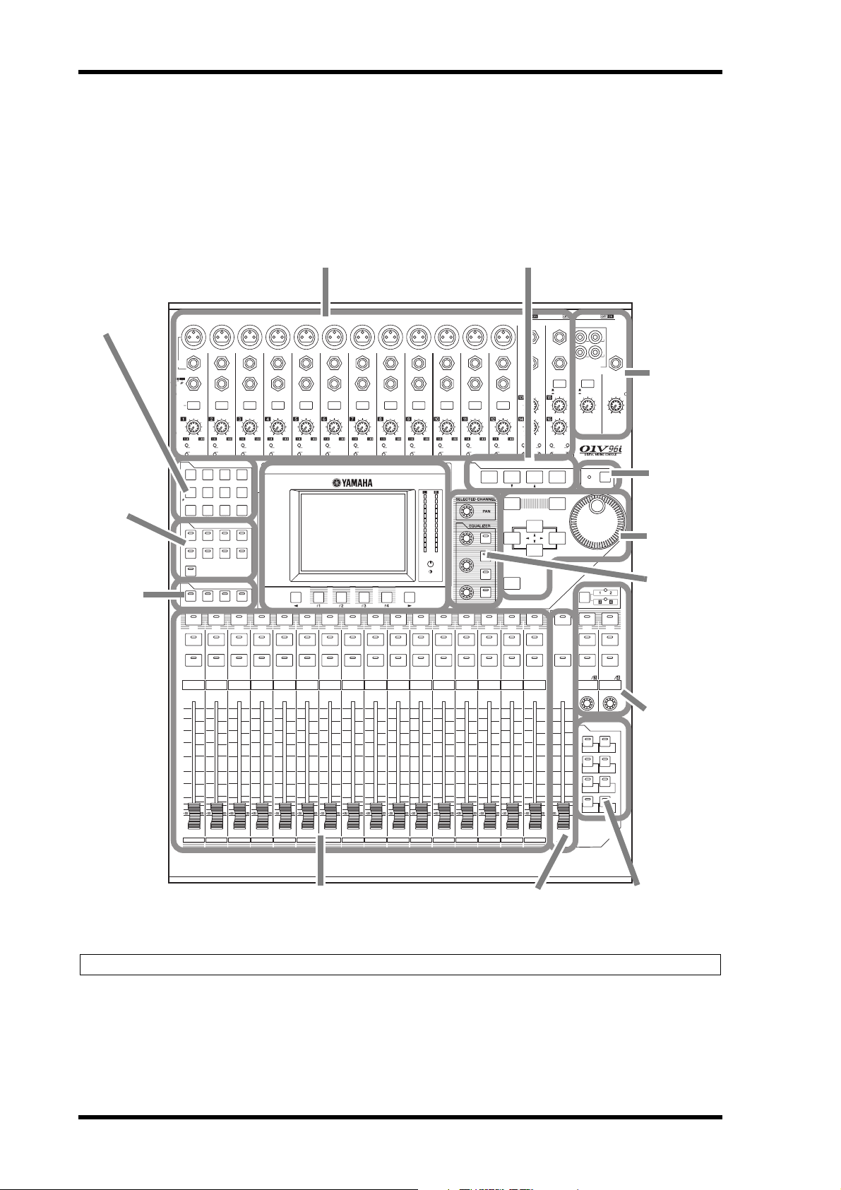
AD Input Section (p. 7)
SELECTED
CHANNEL
Section (p. 9)
Monitor Out
& Headphones Section (p. 7)
SOLO Section
(p. 9)
Channel Strip Section (p. 7) STEREO Section (p. 8) USER DEFINED KEYS
Section (p. 9)
Data Entry
Section (p. 9)
LAYER Section
(p. 8)
SCENE MEMORY Section (p. 9)
Display Section
(p. 9)
DISPLAY ACCESS
Section (p. 8)
ST IN Section
(p. 8)
FADER MODE
Section (p. 8)
Control Surface & Rear Panel
Control Surface
Note: For details on the function of each item, refer to “Control Surface & Rear Panel” in the Owner’s Manual.
01V96i—Reference Manual
Page 7

Control Surface 7
PEAK
SIGNAL
PEAK
SIGNAL
PEAK
SIGNAL
PEAK
SIGNAL
PEAK
SIGNAL
PEAK
SIGNAL
PEAK
SIGNAL
PEAK
SIGNAL
PEAK
SIGNAL
PEAK
SIGNAL
PEAK
SIGNAL
CH15
/
16
2TR IN
+4
-26
GAIN
+4
-26
GAIN
+4
-26
GAIN
GAIN
+4
-26
GAIN
20dB
-16
-60
GAIN
20dB
-16
-60
GAIN
20dB20dB20dB20dB20dB20dB20dB
-16
-60
GAIN
-16
-60
GAIN
-16
-60
GAIN
-16
-60
GAIN
-16
-60
GAIN
-16
-60
GAIN
-16
-60
PAD
A
B
A
B
A
B
A
B
A
B
A
B
A
B
A
B
A
B
16
1513
121110943215
14
INSERT I/O INSERT I/O INSERT I/O INSERT I/O INSERT I/O INSERT I/O INSERT I/O INSERT I/O INSERT I/O
CH1-4
INPUT
(BAL)
INSERT
OUTIN
(UNBAL)
13 14 15 16
1
3
4
5
6
7
8
2
PHONES
MONITOR
OUT
MONITOR
2TR IN
LEVEL
PHONES
LEVEL
0
10
0
10
L
R
IN OUT
2TR
-10dBV
(UNBAL)
PHANTOM +48V
CH9-12CH5-8
1
2
3
4
5
SOLO
ON
SEL
AUX 1
40
50
60
70
30
5
10
15
20
0
20
30
40
50
15
5
+10
5
10
0
1
1
17
1
2
3
4
AD Input Section
1 INPUT connectors A/B
2 INPUT connectors 13–16
3 INSERT I/O connectors
4 PAD switches
5 GAIN controls
6 PEAK indicators
7 SIGNAL indicators
8 AD15/16 selector
Control Surface & Rear Panel
Monitor Out & Headphones
Section
1 2TR IN/OUT connectors
2 Monitor Source selector
3 MONITOR LEVEL control
4 PHONES LEVEL control
5 PHONES jack
Channel Strip Section
1 [SEL] buttons
2 [SOLO] buttons
3 [ON] buttons
4 Channel faders
01V96i—Reference Manual
Page 8

8 Control Surface & Rear Panel
DISPLAY ACCESS
DYNAMICS
EQ EFFECT VIEW
PATCH
UTILITYMIDISCENE
DIO/SETUP
/ INSERT/
DELAY
PAN/
ROUTING
PAIR/
GROUP
1 2 3
9
0 A B
4
5
6
8
7
UTILITYMIDISCENE
DIO/SETUP
1-16 17-32 MASTER REMOTE
LAYER
1 2 3
STEREO Section
1 [SEL] button
2 [ON] button
3 [STEREO] fader
ST IN Section
1 [ST IN] button
2 [SEL] buttons
3 [SOLO] buttons
4 [ON] buttons
5 Level controls
1
2
3
4
5
1
2
3
ST IN
SEL SEL
SOLOONSOLO
ON
ST IN 1 ST IN 2
SEL
ON
0
5
10
15
20
30
40
50
60
70
STEREO
DISPLAY ACCESS Section
1 [SCENE] button
2 [DIO/SETUP] button
3 [MIDI] button
4 [UTILITY] button
5 [ /INSERT/DELAY] button
6 [PAN/ROUTING] button
7 [PAIR/GROUP] button
8 [PATCH] button
9 [DYNAMICS] button
0 [EQ] button
A [EFFECT] button
B [VIEW] button
LAYER Section
1 [1–16]/[17–32] buttons
2 [MASTER] button
3 [REMOTE] button
FADER MODE Section
1 [AUX 1]–[AUX 8] buttons
2 [HOME] button
1
2
01V96i—Reference Manual
FADER MODE
AUX 1AUX 2AUX 3AUX
AUX
7
AUX
6
AUX
5
HOME (METER)
Tip : The ST IN section is not affected by the layer settings.
4
AUX
8
Page 9

Control Surface 9
STEREO
OVER
0
-3
-6
-9
-12
-15
-18
-24
-30
-36
-48
4
1
5
2
3
6
Tab S croll arrow
HIGH
HIGH-MID
LOW-MID
LOW
Q
FREQUENCY
GAIN
2
3
4
5
6
1
7
8
USER DEFINED
KEYS
12
34
56
78
1
ENTER
DEC INC
2
3
1
4
SOLO CLEAR
1 2
Display Section
1 Display
2 Stereo meters
3 Contrast control
4 [F1]–[F4] buttons
5 Left Tab Scroll [ ] button
6 Right Tab Scroll [ ] button
SCENE MEMORY Section
SCENE MEMORY
STORE
13
2
RECALL
1 [STORE] button
2 Scene Up [ ] / Down [ ] buttons
3 [RECALL] button
USER DEFINED KEYS
Section
1 [1]–[8] buttons
Control Surface & Rear Panel
SELECTED CHANNEL Section
1 [PAN] control
2 [HIGH] button
3 [HIGH-MID] button
4 [LOW-MID] button
5 [LOW] button
6 [Q] control
7 [FREQUENCY] con-
trol
8 [GAIN] control
Data Entry Section
1 Parameter wheel
2 [ENTER] button
3 [DEC] & [INC] buttons
4 Left, Right, Up, Down ([ ]/[ ]/[ ]/[ ]) cur-
sor buttons
SOLO Section
1 [SOLO] indicator
2 [CLEAR] button
01V96i—Reference Manual
Page 10

10 Control Surface & Rear Panel
PHANTOM +48V (p. 10)
Power Section (p. 11)
AD Output Section
(p. 10)
SLOT Section (p. 11)
MIDI/USB Section
(p. 10)
Digital I/O Section
(p. 10)
321
42153
Rear Panel
PHANTOM +48V
321
1 CH1–4 ON/OFF switch
2 CH5–8 ON/OFF switch
3 CH9–12 ON/OFF switch
AD Output Section
1 MONITOR OUT connectors L/R
2 OMNI OUT connectors 1–4
3 STEREO OUT connectors L/R
Digital I/O Section
1 WORD CLOCK OUT connector
2 WORD CLOCK IN connector
3 ADAT IN/OUT connectors
4 2TR OUT DIGITAL COAXIAL
5 2TR IN DIGITAL COAXIAL
MIDI/USB Section
01V96i—Reference Manual
21
1 MIDI IN/THRU/OUT ports
2 TO HOST USB port
Page 11

Rear Panel 11
1
21
SLOT Section
1 SLOT
Power Section
1 POWER ON/OFF switch
2 AC IN connector
Control Surface & Rear Panel
01V96i—Reference Manual
Page 12

12 Analog I/O & Digital I/O
AA
21
BB
INPUT
(BAL)
16
1513
14
INSERT I/O INSERT I/O
INSERT
OUTIN
(UNBAL)
20dB
PAD
20dB
GAIN
-16
-60
PEAK
SIGNAL
GAIN
L
R
IN OUT
2TR
-10dBV
(UNBAL)
Analog I/O & Digital I/O
This chapter describes the 01V96i’s analog and digital
input/output connectors as well as the basic operations
involving the digital I/Os.
Analog Inputs & Outputs
Input Section
The 01V96i’s top panel features input connectors, which
enable you to connect microphone and line-level sources.
• INPUT connectors A 1–12
These balanced TRS-type
phone connectors accept
line-level and microphone signals. The nominal input range is
–60 dB through +4 dB. The phantom [+48V] switches on
the rear panel turn on or off the +48V phantom power
feed to these inputs.
• INPUT connectors B 1–12
These balanced TRS-type connectors accept line-level and
microphone signals. The nominal input range is –60 dB
through +4 dB.
You cannot use same-numbered INPUT A and INPUT B
connectors simultaneously. (For example, you cannot use
INPUT A-2 and INPUT B-2 at the same time.) If you
connect cables to A and B connectors of the same number, only the signal from INPUT B is effective (e.g., B-2
takes priority over A-2).
•Phantom Power
Inputs 1 through
12 feature switchable +48V phantom powering for use with condenser-type microphones and direct boxes. The phantom
[+48V] switches on the rear panel turn on or off the +48V
phantom power feed to the corresponding inputs.
•PAD switches
Inputs 1 through 12 feature pad
switches, which attenuate input
signals by 20 dB. These switches
are effective on both INPUT A and B signals.
•GAIN controls
Inputs 1 through 16 feature
rotary gain controls that adjust
input sensitivity. Input sensitivity
for INPUT connectors 1–12
ranges from –16 dB to –60 dB when the Pad is off, and
from +4 dB to –40 dB when the Pad is on. Input sensitivity for INPUT connectors 13–16 ranges from +4 dB to
–26 dB.
•PEAK & SIGNAL Indicators
The SIGNAL indicator lights up
when the input signal level at
INPUTs 1–16 exceeds –34 dB.
The PEAK indicator lights up when the input signal level
is 3 dB below clipping.
•2TR IN connectors
These unbalanced RCA phono connectors accept line-level signals from
devices such as CD players.
When the AD 15/16 source selector is
turned on (pushed in), signals input at
these conductors are routed to AD
Inputs 15 and 16. When the Monitor source selector is
turned on (pushed in), you can monitor these signals
from the MONITOR OUT connectors.
•INPUT connectors 13–16
These balanced TRS-type phone connectors accept line-level signals. When
the AD 15/16 source selector is turned
on (pushed in), signals from INPUT 15
and 16 are ignored. Instead, signals from
the 2TR IN connector will be routed to AD Input Channels 15 and 16.
Tip: You can patch signals input from the INPU T connectors
to any Input Channels. (See page 43 for information on
patching input signals to Input Channels.)
• INSERT I/O connectors
These TRS-type phone connectors
are used to insert external devices,
such as effects processors, into AD Input Channels.
01V96i—Reference Manual
Page 13

Digital Inputs & Outputs 13
L
R
IN OUT
2TR
-10dBV
(UNBAL)
Output Section
The 01V96i top and rear panels feature output connectors
that enable you to connect a monitoring system, effects processors and other line-level devices.
• MONITOR OUT connectors L/R
These balanced TRS-type phone connectors output monitoring signals or
input signals routed from the 2TR IN
connectors. The nominal output level
is +4 dB.
Use the Monitor source selector in the Monitor Out &
Headphones section to select the signal output from these
connectors.
•OMNI OUT connectors 1–4
These balanced
TRS-type phone connectors output any Bus
Outs or Input Channel
Direct Outs. The nominal output level is +4 dB.
Tip : Any signal path can be patched to the OMNI OUT connectors. (See page 44 for more information on patching signals to the OMNI OUT connectors.)
• STEREO OUT connectors L/R
These balanced XLR-3-32-type
connectors output the Stereo Out
signals. The nominal output level
is +4 dB.
•2TR OUT connectors
These unbalanced RCA phono connectors output line-level signals to a
connected recorder or other external
device. These connectors always output the Stereo Out signals.
Analog I/O & Digital I/O
Digital Inputs & Outputs
The 01V96i rear panel features digital input and output connectors that enable you to connect external digital devices.
Any signal path can be patched to these digital inputs and
outputs.
You can also add analog and digital I/Os by installing an
optional I/O card in the slot.
Digital I/O Connectors
•2TR IN DIGITAL connector
2TR IN DIGITAL is an RCA phono connector
and accepts consumer format (IEC 60958)
digital audio. You can patch digital signals
input at this connector to any Input Channel
(page 43).
• 2TR OUT DIGITAL connector
This RCA phono connector outputs consumer format (IEC 60958) digital audio. You
can patch any Bus outs or Input channel
Direct Outs to this output (page 45).
•ADAT IN connector
This TOSLINK connector accepts 8-channel ADAT optical format signals, which can be patched to any Input
Channel (page 43).
• ADAT OUT connector
This TOSLINK connector outputs an 8-channel ADAT
optical format signal. You can patch any Bus Outs or
Input Channel Direct outs to this output (page 44).
SLOT
This slot allows you to install an optional mini-YGDAI
(Yamaha General Digital Audio Interface) I/O card. This card
offers AD/DA conversion, and various analog I/O options
and digital I/O interfaces in all the popular digital audio interconnect formats, including AES/EBU, ADAT, and Tascam.
You can patch signals input at these card connectors to any
Input Channels or Insert Ins (see page 43).
You can patch the card outputs to Bus Outs or Input Channel
Direct Outs (see page 46).
For details on the mini-YGDAI I/O cards that are currently
usable, refer to “I/O Slot Specifications” in the Owner’s Manual.
For the latest information about mini-YGDAI I/O cards, refer
to the Yamaha Professional Audio website.
http://www.yamahaproaudio.com/
01V96i—Reference Manual
Page 14

14 Analog I/O & Digital I/O
1
2
3
4
5
6
Converting Sampling Rates of Signals Received at I/O Card Inputs
An optional MY8-AE96S Digital I/O card features sampling
rate converters, so you can easily convert the sampling frequency of digital inputs to the current 01V96i sampling rate.
1. Press the DISPLAY ACCESS [DIO/SETUP] but-
ton repeatedly until the DIO/Setup | Format
page appears.
Use the buttons in the SRC sections to turn the sampling
rate converters on and off. You can turn the sampling rate
converters of the digital I/O card on or off in pairs (odd &
even channels, in this order).
Monitoring Digital Input Channel Status
You can view and monitor the Channel Status (sampling rate,
emphasis, etc.) of digital audio signals connected to the 2TR
Digital Inputs and Slot Inputs as follows.
1. Press the DISPLAY ACCESS [UTILITY] button,
then press the [F2] button.
The Utility | CH Status page appears.
On this page, use the following buttons to select a slot or
connector for which you want to view the channel status.
Tip: The FS box on the Word Clock page displays the sampling frequency at which the 01V96i is currently operating.
Note: The sampling rate converter is available only on the
Yamaha MY8-AE96S Digital I/O card. If you have installed
another type of I/O card in the slot, or if no card is installed
in the 01V96i, the buttons in the SRC sections are disabled.
2. Use the cursor buttons to move the cursor to
any two-channel button in the SRC sections,
then press [ENTER].
The sampling rate converter for the selected 2-channel
input turns on or off. When on, the sampling rate of the
received digital audio is converted to the 01V96i’s current
sampling rate.
1 2TR IN
This button enables you to view the Channel Status of
input signals connected to the 2TR Digital Inputs.
2 SLOT
These buttons enable you to view the Channel Status of
each two adjacent (odd and even, in this order) channel
signals connected to the digital I/O card installed in the
slot.
2. Move the cursor to the desired input or slot
button, then press [ENTER].
Channel Status information for the selected input is displayed. However, if a mini-YGDAI I/O card other than
AES/EBU format is installed, Channel Status information
will be grayed out. Channel Status information includes
the following items:
3 FS
Indicates the sampling rate. If no signal is being input, or
if the incoming wordclock is not synching to the internal
clock, “Unlock” appears.
4 EMPHASIS
Indicates the Emphasis on/off status.
5 CATEGORY
Indicates the status of “Category Code Bit” included in
the IEC958 Part 2 (S/PDIF-Consumer) format. This
parameter can display the following values:
01V96i—Reference Manual
Page 15

Dithering Digital Outputs 15
Parameter value Description
General Tempor aril y use d
Laser Optical Laser optical device
D/D Conv
Magnetic
D.Broadcast Digital broadcast reception
Instruments
A/D Conv
A/D Conv with (C)
Solid Memory Solid memory device
Experimental Experimental device
Unknown Unknown
Note: “AES/EBU” appears in the Category row when you are
monitoring IEC958 Part 3 (AES/EBU-Professional) format
signals (that do not include Category Code Bit).
Digital - Digital converter and
signal processing device
Magnetic tape device and magnetic disk device
Musical instrument, microphone, and sources that generate string signals
A/D converter (without copyright information)
A/D converter (with copyright
information)
6 COPY
Indicates the status of copy protection information
included in the IEC958 Part2 (S/PDIF-Consumer) format signals. “OK” appears if copying is allowed. “Prohibit” appears if copy-protected.
Analog I/O & Digital I/O
Dithering Digital Outputs
When digital audio is transferred to lower-resolution systems,
truncated bits may generate unpleasant noise. To cancel the
audible effect of this noise, a small complement of noise is
intentionally added to the digital outputs. This process is
called “dithering.”
On the 01V96i, you can dither the 2TR Digital Outputs and
Slot Outputs. For example, you can apply dithering to the
01V96i stereo mix data and record to a 16-bit digital recorder.
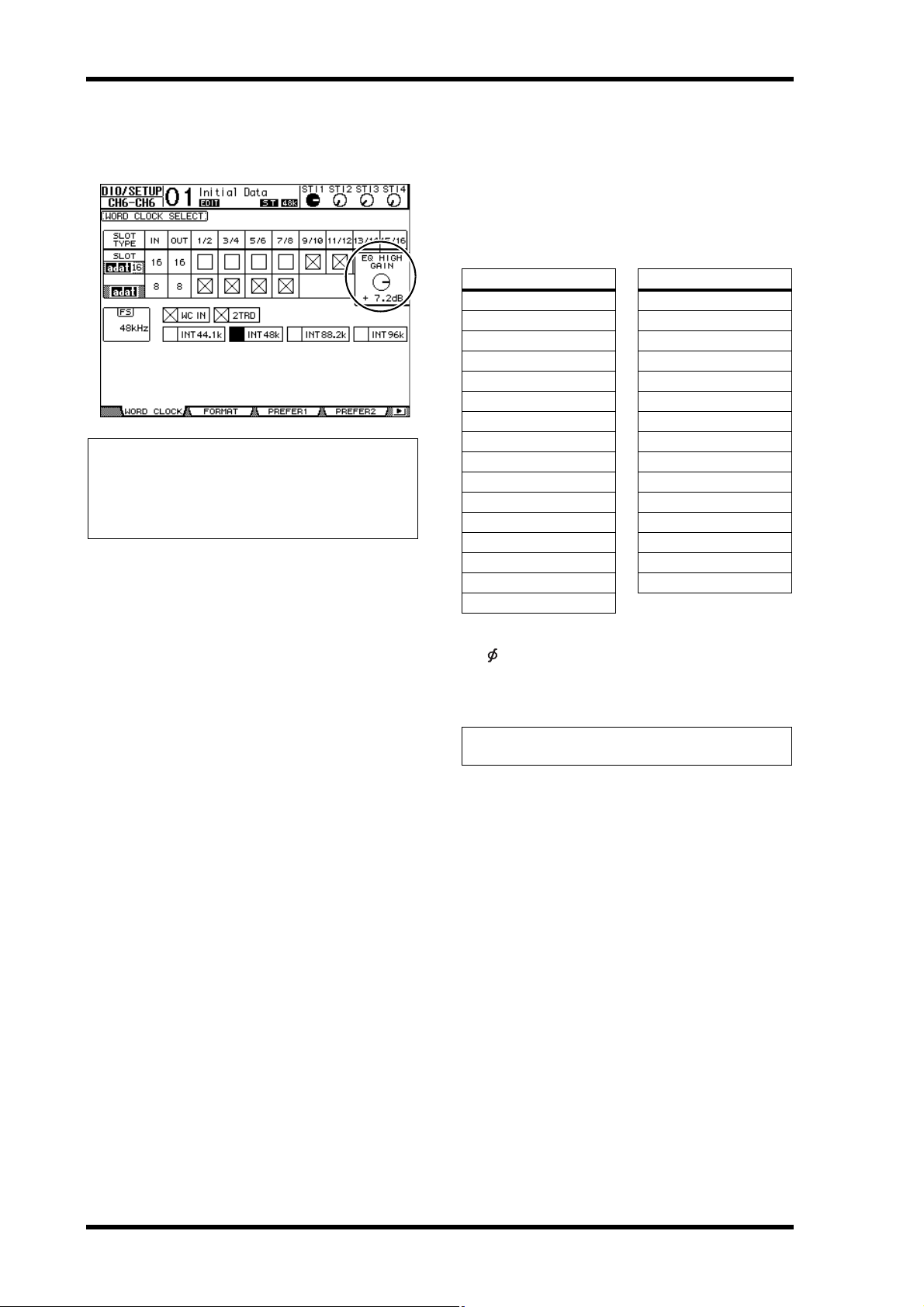
1. Press the DISPLAY ACCESS [DIO/SETUP] but-
ton repeatedly until the DIO/Setup | Format
page appears.
The dithering settings are displayed at the bottom of the
page.
3. If you select the SLOT
button for a slot that
has an MY16-AE card installed, use the 01–08
and 09–16 buttons located in the lower-right
corner of the screen to select a channel group
you wish to display.
2. Move the cursor to the output or channel to
which you want to apply dithering, then
rotate the Parameter wheel or press the
[INC]/[DEC] buttons to select the value that
matches the resolution of the receiving
device.
Note:
• You cannot apply dithering to outputs or channels that are
set to “OFF.”
• Dithering is effective only when the resolution of the
receiving device is lower than that of the 01V96i.
Tip : To copy the currently-selected setting to all channels,
double-click the [ENTER] button. The copy confirmation
window is displayed.
01V96i—Reference Manual
Page 16

16 Analog I/O & Digital I/O
Setting the Transfer Format for Higher Sampling Rates
To operate the 01V96i at higher sampling frequencies
(88.2 kHz or 96 kHz) and transfer digital audio signals to and
from connected external devices, you must set the data transfer format in accordance with the sampling frequencies supported by the external devices.
1. Press the DISPLAY ACCESS [DIO/SETUP] but-
ton repeatedly until the DIO/Setup | Word
Clock page appears.
2. Select INT88.2k or INT96k as the wordclock
source.
Note: When the 01V96i operates at a high sampling rate
(88.2 k Hz or 96 kHz), only two internal effects processors are
available.
3. Press the DISPLAY ACCESS [DIO/SETUP] but-
ton repeatedly until the DIO/Setup | Format
page appears.
•DOUBLE SPEED
In Double Speed mode, digital audio data is received and
transmitted at the current high sampling rate (i.e.,
88.2 kHz or 96 kHz). Select this mode if the devices that
support the higher sampling rates transmit or receive
data.
Note: You can select this setting only for slots in which a digital I/O card that inputs/outputs double-speed digital audio
data (e.g., MY8-AE96, MY8-AE96S) is installed.
•SINGLE
In Single mode, digital audio data is received and transmitted at a sampling rate that is half (44.1/48 kHz) the
current higher sampling rate of the 01V96i. For example,
this is useful when you want to receive 44.1 kHz digital
signals from an external digital device while the 01V96i is
operating at 88.2 kHz.
Note: You cannot select this setting for slots in which a digital
I/O card that inputs/outputs double-speed digital audio data
(e.g., MY8-AE96, MY8-AE96S) is installed.
Tip: The parameter fields display “–” if the slot contains no
I/ O c ard or i f a n AD /D A ca rd o r o the r I /O c ard tha t d oes not
allow you to set the transfer format has been installed.
1
4. Use the cursor buttons to move the cursor to
an IN/OUT parameter field (
the Parameter wheel or press the [INC]/[DEC]
buttons to set the data transfer format.
The IN/OUT parameters are used to set one of the following data transfer formats for each slot input and output.
• DOUBLE CHANNEL
In Double Channel mode, digital audio data is received
and transmitted as mono signals at a sampling rate that is
exactly half (44.1/48 kHz) the current higher sampling
rate. Data is handled by two channels. This is useful when
you want to transfer data between the 01V96i operating at
a higher sampling rate and an external digital device that
supports 44.1/48 kHz.
1), then rotate
Note: Double Channel mode reduces the total number of
inputs or outputs on the corresponding slot. The even-numbered channels are disabled.
01V96i—Reference Manual
Page 17
Input Channels 17
INPUT PATCH
INPUT PATCH
Input Channels
This chapter describes how to adjust the 01V96i’s Input
Channel parameters.
About Input Channels
The input Channel section enables you to adjust the level and
tone of the signals input to the 01V96i (and the signals output
from the internal Effects processors 1–4), and route the signals to Buses 1–8, the Stereo Bus, and Aux Sends 1–8. There
are two types of Input Channels, each featuring slightly different functions: monaural Input Channels 1–32 and stereo ST
IN Channels 1–4.
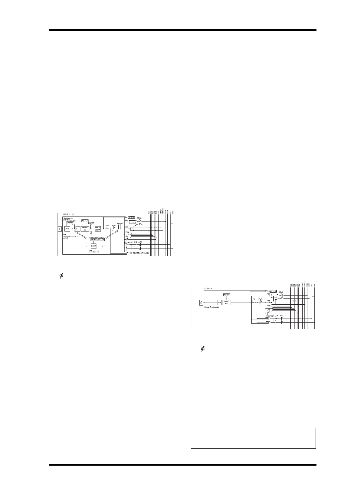
Input Channels 1–32
Each of these monaural Input Channels features a phase
effect, gate, compressor, attenuator, and EQ for signal processing. The following diagram illustrates the Input Channel
1–32 signal flow.
•LEVEL
This section enables you to adjust the input level of the
Input Channel signal.
•PAN
This section enables you to adjust the pan setting of the
signals routed from the Input Channels to the Stereo Bus.
You can also apply the pan setting to a pair of Bus channels.
• AUX (Aux Send level)
This section enables you to adjust the level of signals
routed to Aux Sends 1–8. The signals can be routed to
Aux Sends from either the pre-fader or post-fader position.
•INSERT
This section enables you to patch input signals to external
devices via the on-board I/O connectors or I/O card, or
insert the internal effect processors. You can patch any
inputs, outputs, or I/O card channels. (Note that this is
different from the INSERT I/O connectors in the AD
Input section.)
• METER
This section enables you to switch the metering position
of the signal levels that are displayed in the Meter page.
For more information on selecting the metering position,
refer to “Viewing the Level Meters” in the Owner’s Manual (booklet).
Input Channels
Input Channels 1–32 feature the following parameters:
• (Phase)
This section switches the phase of input signals.
•GATE
This dynamics processor can be used as a gate or for
ducking.
•COMP (Compressor)
This dynamics processor can be used as compressor,
expander or limiter. The compressor can be pre-EQ,
pre-fader, or post-fader.
•ATT (Attenuator)
This section enables you to attenuate or amplify the level
of signals that will be input to the EQ. The attenuator
enables you to prevent post-EQ signals from clipping and
to correct signal levels that are too low.
• 4 BAND EQ (4-band equalizer)
This parametric EQ features four bands (high, high-mid,
low-mid, and low).
• INPUT DELAY (Input delay)
This section enables you to delay input signals. You can
use this delay to fine-tune the timing between channels,
or as a delay effect with feedback.
• ON (On/Off)
This section enables you to turn the channel on or off.
The channel is muted with the Off setting.
ST IN Channels 1–4
These stereo channels enable you to process stereo signals
using the phase effect, attenuator, and EQ. The following diagram illustrates the ST IN Channel 1–4 signal flow.
ST IN Channels 1–4 feature the following parameters:
• (Phase)
•ATT (Attenuator)
• 4 BAND EQ (4-band equalizer)
• ON (On/Off)
•LEVEL
•PAN
• AUX (Aux Send level)
• METER
For more information on each parameter, refer to the preceding section Input Channel 1–32.
Tip: You can store these channel parameter settings in the Channel library. You can also store the Gate, Compressor, and EQ
parameter settings to the corresponding libraries.
01V96i—Reference Manual
Page 18
18 Input Channels
1
2
Setting the Input Channels from the Display
To set the Input Channel parameters, you can either move the
cursor to the desired parameter on the display and change the
value, or operate the desired button or control on the top
panel to directly change the setting.
This section explains how to set the parameters via the display.
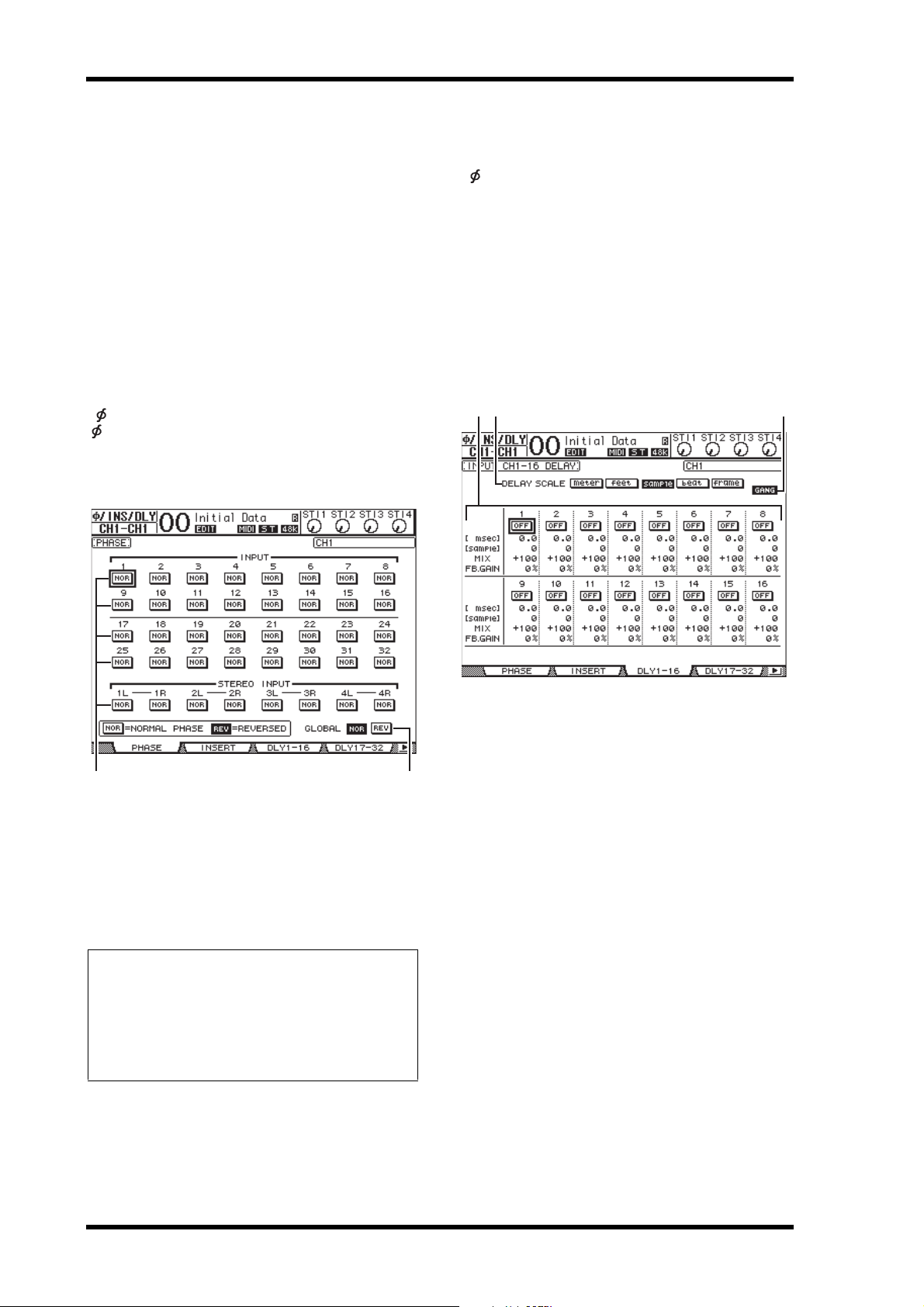
Switching the Signal Phase
To switch the phase of each Input Channel, press the
[ /INSERT/DELAY] button repeatedly until the following
/INS/DLY | Phase page appears.
Move the cursor to the NOR/REV button of the channel for
which you want to change the phase, then press the [ENTER]
or [INC]/[DEC] buttons to change the setting.
Delaying Input Channels
To set the delay for each channel, press the
[ /INSERT/DELAY] button repeatedly until the page listed
below that contains the desired channels appears.
• DLY 1-16 page
This page enables you to set the Delay function for Input
Channels 1–16.
• DLY 17-32 page
This page enables you to set the Delay function for Input
Channels 17–32.
The parameters on these two pages (and the procedure for
setting them) are the same.
213
1 NOR/REV
These buttons switch the corresponding Input Channel
phase. NOR buttons indicate normal phase, and REV
buttons indicate reversed phase.
2 GLOBAL
The GLOBAL NOR/REV buttons allow you to set the
phase for all Input Channels simultaneously.
Tip:
• The name of the currently-selected channel is indicated in the
upper-right corner of the screen.
• You can set the phase separately for each of the ST IN Channels
or for each channel in a channel pair. If you select ed the desired
ST IN Channel using the corresponding [SEL] button, pressing
the same [SEL] button repeatedly will toggle between channels
L and R.
1 DELAY SCALE
The following buttons determine the units of the delay
value shown below the msec value.
• meter........................Units are set to meters.
• feet ............................Units are set to feet.
• sample......................Units are set to samples.
• beat...........................Units are set to beats.
• frame........................Units are set to timecode frames.
2 GANG button
When this button is turned on (highlighted), the delay
time for each channel in a channel pair can be set simultaneously. When this option is turned off, the delay time
can be set for each channel in a channel pair individually.
3 Channel section
You can set individual delay parameters here. The delay
parameters include the following items:
•ON/OFF
This button switches the corresponding channel delay on
or off.
•msec
This parameter sets the delay time in milliseconds.
• meter/feet/sample/beat/frame
The delay time can be set using units of meters, feet, samples, beats, or frames, which you select by using the
DELAY SCALE buttons.
01V96i—Reference Manual
Page 19

Setting the Input Channels from the Display 19
3 4 521
76
•MIX
This parameter sets the mix balance of dry (Input Channel) and wet (delayed) signals.
•FB.GAIN
This parameter sets the amount of delay feedback.
Tip:
• This function is unavailable for the ST IN Channels.
• The delay time range depends on the sampling rate at which
the 01V96i is operating.
• If you select the DELAY SCALE meter or feet button, the distance value can be converted to the delay time based on sonic
speeds (about 343.59 m/sec at 20 degrees Celsius). This option
is useful if you wish to correct the timing difference between
two sound sources that are far apart.
• If you select the DELAY SCALE beat button, a parameter box
for setting a note that represents the beat and a parameter box
for a tempo (BPM) setting appear below the DELAY SCALE
parameter. Setting the note and BPM settings in these parameter boxes enables you to set a delay time that synchronizes to
the song tempo.
Gating Input Channels
To set the Input Channel gates, use the [SEL] buttons to select
the desired Input Channel, then press the DISPLAY ACCESS
[DYNAMICS] button, then press the [F1] button. The
Dynamics | Gate Edit page appears.
2 STEREO LINK
This parameter’s ON/OFF button enables you to pair
gates for stereo operation even when the Input Channels
are not paired.
3 CURVE
This area displays the current gate curve.
4 TYPE
This area displays the current gate type (GATE or DUCKING).
Note: You cannot change the gate type on this page. To
change the gate type, recall a program that uses the desired
gate type from the Gate library.
5 Meters
These meters indicate the levels of the post-gate signals
and the amount of gain reduction.
6 ON/OFF
The ON/OFF button turns the currently-selected Input
Channel’s gate on or off.
7 PARAMETER
These controls enable you to set the gate parameters. (See
page 148 for more information on the parameters.)
Tip :
• This function is unavailable for the ST IN Channels.
• You can store the gate settings in the Gate library, which
features preset programs that can be used for various
applications (see page 79).
Input Channels
1 KEYIN SOURCE
Select one of the following buttons to determine the trigger source for the currently-selected Input Channel’s gate.
• SELF......................... The selected channel’s own input sig-
• CHANNEL ............. Another Channel’s input signal is the
• AUX ......................... An Aux Send signal is the trigger
nal is the trigger source.
trigger source. Select the desired
channel in the parameter box below
the CHANNEL button.
source. Select the desired bus in the
parameter box below the AUX button.
01V96i—Reference Manual
Page 20

20 Input Channels
Compressing Input Channels
To set the Input Channel compressors, use the [SEL] buttons
to select the desired Input Channel, then press the DISPLAY
ACCESS [DYNAMICS] button, then press the [F3] button to
display the Dynamics | Comp Edit page.
3 4 521
76
1 POSITION
Use the Parameter wheel, or the [INC]/[DEC] buttons to
select the position of the compressor within the channel
from the following options:
• PRE EQ....................Immediately before EQ (default)
• PRE FADER ...........Immediately before the fader
• POST FADER ........Immediately after the fader
Attenuating Input Channels
To set the attenuator for each Input Channel, press the DISPLAY ACCESS [EQ] button, then press the [F3] button to
display the EQ | In Att page.
Move the cursor to the knob for the desired Input Channel,
then rotate the Parameter wheel to set the amount of attenuation in the range of –96 dB to +12 dB.
Tip : You can also set the attenuation amount (in dB) for the currently-selected channel on the EQ | EQ Edit page.
2 STEREO LINK
This ON/OFF button enables you to pair compressors for
stereo operation even when channels are not paired.
3 CURVE
This area displays the current compressor curve.
4 TYPE
This field indicates the compressor type used by the currently-selected channel’s compressor
(COMP/EXPAND/COMP (H)/COMP (S)).
Note: You cannot change the Compressor type on this page.
To change the compressor type , recall a program that uses the
desired compressor type from the compressor library.
5 Meters
These meters indicate the levels of the post-compressor
signals and the amount of gain reduction.
6 ON/OFF
The ON/OFF button turns the currently-selected Input
Channel’s compressor on or off.
7 PARAMETER section
These controls enable you to set the compressor parameters. (See page 149 for more information on the parameters of each compressor type.)
Tip:
• This function is unavailable for the ST IN Channels.
• You can store the compressor settings in the compressor
library, which features preset programs that can be used
for various applications (see page 80).
01V96i—Reference Manual
Page 21

Setting the Input Channels from the Display 21
6
51 2 3 4
EQ’ing Input Channels
The 01V96i’s Input Channels feature 4-band (LOW,
LOW-MID, HIGH-MID, HIGH) parametric EQ. The
LOW-MID and HIGH-MID bands are a peaking type of EQ.
The LOW and HIGH bands can be set to shelving, peaking,
or HPF and LPF respectively.
1. Press the [SEL] button of the channel for
which you want to adjust EQ.
2. Press the DISPLAY ACCEESS [EQ] button, then
press the [F1] button to display the EQ | EQ
Edit page.
6 LOW, L-MID, H-MID, HIGH sections
These sections contain the Q, Frequency (F), and Gain
(G) parameters for the four bands. These parameter values range as follows:
LOW-
Parameter LOW
HPF, 10.0
Q
Frequency
Gain
1. The LOW and HIGH GAIN controls function as filter
on/off controls when Q is set to HPF or LPF respectively.
Tip :
• The LOW-band EQ functions as a high-pass filter when
the Q para meter in the LOW section i s set to HPF. It functions as a shelving-type EQ when the Q parameter is set
to L.SHELF.
• The HIGH-band EQ functions as a low-pass filter when
the Q parameter in the HIGH section is set to LPF. It functions as a shelving-type EQ when the Q parameter is set
to H.SHELF.
to 0.10
(41 steps),
L.SHELF
21.2 Hz to 20.0 kHz
(120 steps per 1/12 octave)
–18.0 dB to +18.0 dB (0.1 dB steps)
HIGH-
MID
MID
10.0 to 0.10
(41 steps)
(41 steps),
Input Channels
HIGH
LPF, 10.0
to 0.10
H.SHELF
1
The parameters on this page are described below:
1 EQ ON
The ON/OFF button turns the currently-selected Input
Channel’s EQ on or off. You can press the [ENTER] button to turn the EQ on or off as long as the cursor is located
on any parameter other than TYPE.
2 TYPE
Selects the type of EQ. TYPE I is the EQ type used on legacy Yamaha 02R series digital mixing consoles. The
TYPE II algorithm minimizes the interference between
bands.
3 ATT
Determines the amount of pre-EQ signal attenuation in
dB. It is the same Attenuator parameter that appears on
the EQ | ATT In page.
4 CURVE
This area displays the current EQ curve.
5 Meters
These meters indicate the post-EQ signal levels of the
currently-selected Input Channel and its available pair
partner.
3. Move the cursor to the desired parameter,
then rotate the Parameter wheel to change
the value.
Tip :
• The EQ settings for the ST IN Channels L & R are linked
to each other.
• You can also press the buttons in the SELECTED CHANNEL section to select the desired band and use the rotary
controls to directly edit the Q, F, and G parameters (see
page 25).
• You can store the EQ settings in the EQ library, which features preset programs that can be used for various applications (see page 147).
01V96i—Reference Manual
Page 22

22 Input Channels
576
1
3
4
8
2
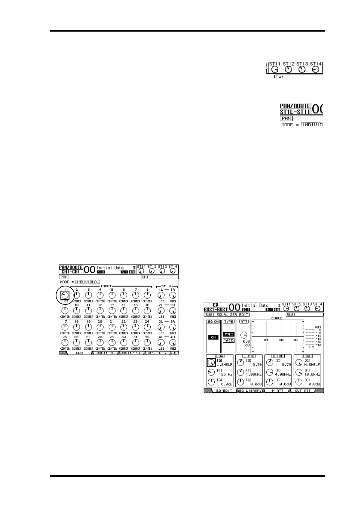
Panning Input Channels
Input Channels can be panned in the range of L63 through
CENTER to R63. To pan each channel, press the
[PAN/ROUTING] button repeatedly until the Pan/Route |
Pan page appears.
1
Move the cursor to the desired Pan control, then rotate the
Parameter wheel to set the value.
2
Routing Input Channels
You can route each Input Channel to the Stereo Bus, Bus 1–8,
or its own Direct Out. With the default setting, signals are
routed only to the Stereo Bus. However, you can patch signals
to a single or multiple destinations, if necessary.
1. Press the DISPLAY ACCESS [PAN/ROUTING]
button repeatedly until the page listed below
that contains the desired channels appears.
•ROUT1-16 page
This page enables you to change the routing for Input
Channels 1–16.
•ROUT17-ST1 page
This page enables you to change the routing for Input
Channels 17–32 and ST IN Channels 1–4.
The parameters on these two pages (and the procedure for
setting them) are the same.
1 Pan controls
These knobs adjust the channel pan settings.
Press the [ENTER] button to reset the currently-selected
Pan control to center.
2 MODE
The MODE parameter determines how paired Input
Channels are panned. There are three Pan modes as follows:
• INDIVIDUAL
In Individual mode, paired Input Channel pan controls operate independently.
•GANG
In Gang mode, paired Input Channel
pan controls operate in unison, maintaining the current pan range.
•INV GANG
In Inverse Gang mode, paired Input
Channel pan controls operate in unison
but move in opposite directions.
Tip:
• You can adjust the pan setting for the ST IN Channels L/R sep-
arately.
• You can als o adjust the p an setting for the Input Channels u sing
the PAN control in the SELECTED CHANNEL section.
• Surround Pan is available when the 01V96i is in Surround
mode. See page 52 for more information on Surround Pan.
1 PAN buttons
These buttons determine whether the channel’s Pan setting is applied to the Bus outs. In surround mode, they
also determine whether the Surround Pan setting is
applied to the Bus Outs.
2 Bus buttons 1–8
These buttons route the currently-selected Input Channel
to the Bus Outs. If the 01V96i is in Surround mode, the
button indicators change as follows, depending on the
selected Surround mode:
Bus buttons 12345678
Surround mode: 3-1 LRCS5678
Surround mode: 5.1 LRLsRsCE78
Surround mode: 6.1 LRLsRsCBsE8
L=Left, R=Right, C=Center, S=Surround, Ls=Left Surround
Rs=Right Surround, E=Low Frequency Effect, Bs=Back
Surround
The above table shows the default assignment. The actual
assignment may vary, depending on the settings on the
DIO/Setup | Surround Bus Setup page.
01V96i—Reference Manual
Page 23

Setting the Input Channels from the Display 23
2
1
3 54 6
8
7
3 S
When this button is turned on, the currently-selected
Input Channel is routed to the Stereo Bus.
4 D
When this button is turned on, the currently-selected
Input Channel is routed to its Direct Out. See page 46 for
more information on the Direct Out.
5 ALL STEREO
This button turns on the S button for all channels on the
page.
6 ALL BUS
This button turns on the Bus buttons 1–8 for all channels
on the page.
7 ALL CLEAR
This button clears all routing assignments on the page.
8 SURROUND MODE
This field displays the current Surround mode.
Tip: The routings of the ST IN Channels L/R are linked. The D
button is unavailable for the ST IN Channels.
Viewing Input Channel Settings
Input Channels
You can view and adjust parameter settings for the currently-selected Input Channel on the View | Parameter or
Fader pages.
■ Viewing the Gate, Compressor, and
EQ Settings
To display the View | Parameter page for a specific Input
Channel, use the corresponding [SEL] button to select the
desired channel, then press the DISPLAY ACCESS [VIEW]
button repeatedly.
Move the cursor to a parameter you wish to change, then
rotate the Parameter wheel or press the [INC]/[DEC] buttons
or [ENTER] button to modify the setting.
The following parameters are available (sections marked with
an asterisk (*) are unavailable for the ST IN Channels).
1 GATE section (*)
This section enables you to turn the gate-type dynamics
processor on or off and set the parameters. (See page 19
for more information.)
2 COMP section (*)
This section enables you to turn the compressor-type
dynamics processor on or off and set the parameters. (See
page 20 for more information.)
3 INSERT section (*)
This section enables you to turn the Insert on or off and
patch the Insert In and Out. (See page 47 for more information.)
4 EQ section
This section enables you to set various EQ parameters.
(See page 21 for more information.)
5 Meters
These meters indicate the signal levels of the currently-selected Input Channel and its available pair partner.
6 (Phase) section
You can reverse the signal phase of the currently-selected
Input Channel. (See page 18 for more information.)
01V96i—Reference Manual
Page 24
24 Input Channels
7 DELAY section (*)
This section enables you to set the currently-selected
channel’s Delay function. (See page 18 for more information.)
8 PAIR section (*)
This section indicates whether or not channels are paired.
The heart icon ( ) is in one piece when channels are
paired. The heart icon is broken ( ) when channels are
not paired. (See page 26 for more information.)
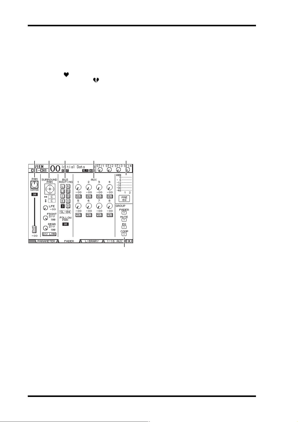
■ Viewing the Pan, Fader, and Aux
Send Level Settings
To display the View | Fader page of a certain Input Channel,
use the corresponding [SEL] button to select the desired
channel, then press the DISPLAY ACCESS [VIEW] button
repeatedly.
Move the cursor to a parameter you wish to change, then
rotate the Parameter wheel or press the [INC]/[DEC] buttons
to modify the setting.
321 4 5
3 BUS ROUTING/FOLLOW PAN section
•BUS ROUTING
This section enables you to select a destination Bus for the
selected channel. When the D button is turned on, the
channel signal is patched to the Direct Out selected in the
parameter box below the button. (The D button is
unavailable for the ST IN Channels.)
• FOLLOW PAN
This button determines whether the Input Channel’s Pan
setting is applied to the paired Bus Outs (Follow Pan
function). When the button is turned off, the Follow Pan
function is disabled and an identical signal is sent to the
paired Bus Outs. In surround mode, it also determines
whether the Surround Pan setting is applied to the Bus
Outs.
4 AUX section
•AUX
These controls set the currently-selected Input Channel’s
Aux Send 1–8 levels and positions. (See page 36 for more
information on Aux Sends.)
5 Meter section
•Meters
These meters indicate the levels of the currently-selected
Input Channel.
1 PAN/ON/Fader section
•PAN control
This control adjusts the currently-selected Input Channel’s Pan parameter.
Press the [ENTER] button to reset the Pan control to
Center.
• ON/OFF button
This button turns on or off the currently-selected Input
Channel.
•Fader
This parameter sets the fader position of the currently-selected Input Channel. The fader knob is highlighted when the fader is set to 0.0 dB.
Press the [ENTER] button to reset the Fader to 0.0 dB.
6
• PRE EQ/PRE FADER/POST FADER
The metering position is displayed below the meters.
6 GROUP section
• FADER/MUTE/EQ/COMP
These buttons indicate which Fader, Mute, EQ, or Comp
group, if any, the currently-selected Input Channel is in. If
the channel is in a group, the group number appears. If
the channel is not in a group, “—” appears. (The compressor is unavailable for the ST IN Channels.)
2 SURROUND PAN section
• SURROUND PAN
The Surround pan parameters for the currently-selected
Input Channel are displayed only when a Surround mode
is selected. See page 52 for more information on Surround pan.
01V96i—Reference Manual
Page 25
Setting the Input Channels from the Control Surface 25
Setting the Input Channels from the Control Surface
You can use the faders, [SEL] buttons, and various buttons
and controls in the SELECTED CHANNEL section on the
top panel to directly control most parameters for Input Channels.
Setting Input Channel Levels
and Panning the Channels
■ Input Channels 1–32
1. Press the LAYER [1–16] or [17–32] button to
select a layer.
2. Press the [SEL] button of the channel for
which you want to adjust the input level
and/or pan settings.
3. Use the faders to set the Input Channel levels.
4. Rotate the SELECTED CHANNEL [PAN] con-
trol to adjust the pan settings.
When you rotate the [PAN] control, the Pan/Route | Pan
page is displayed automatically.
3. Rotate the level control of the desired chan-
nel to set the level.
You can always view the
current channel level at the
top of the display.
4. Rotate the SELECTED CHANNEL [PAN] con-
trol to adjust the pan setting.
The pan setting can be applied to
either ST IN channel L or R. To
switch between channels L and R
for the pan setting, press the same
[SEL] button repeatedly. (The
channel currently being controlled is indicated in the
upper-left corner of the display.)
EQ’ing Input Channels
1. Press the [SEL] button or move the fader for
the channel you wish to control.
2. To control EQ for the currently-selected chan-
nel, press one of the following buttons to
select the band you wish to adjust:
• [HIGH] button...... HIGH band
• [H-MID] button ... HIGH-MID band
• [L-MID] button .... LOW-MID band
• [LOW] button ....... LOW band
3. Use the SELECTED CHANNEL [Q], [FRE-
QUENCY], and [GAIN] controls to adjust the
Q, frequency, and gain of the band selected
in Step 2.
When the Auto EQUALIZER Display (page 109) check
box is on, the 01V96i displays the EQ/EQ Edit page.
Input Channels
■ ST IN Channels 1–4
1. Use the ST IN [ST IN] button to select the
desired ST IN Channels.
The indicators next to the [ST IN] button display the ST
IN Channels currently selected for control by the ST IN
section.
2. Press the [SEL] button for the channel for
which you want to adjust the level and/or pan
settings.
01V96i—Reference Manual
Page 26
26 Input Channels
If the check box is off, the parameter value currently
being adjusted pops up.
See page 21 for more information on EQ.
Tip:
• Pressing and holding down the button selected in Step 2 resets
the corresponding band gain.
• Pressing the SELECTED CHANNEL [HIGH] and [LOW]
buttons simultaneously resets the Q, frequency and gain for
each band.
Pairing Input Channels
On the 01V96i, you can pair adjacent odd-even Input Channels or counterp art channels on Layer 1 and L ayer 2 that share
the same physical fader. Faders and most parame ters of paired
channels are linked for stereo operation. Paired channels’
linked parameters and non-linked parameters (that are available for independent control) are listed below:
Linked parameters Non-linked parameters
[SEL] buttons Input patches
Faders Insert patches
Channel on/off Output patches
Insert on/off Comp insert position
Solo on/off Phase
Solo Safe Delay on/off
Aux on/off Delay time
Aux Send level Delay feedback
Aux Sends as Pre or Post Delay mix
Gate Routing
Comp settings Pan, Follow Pan
EQ settings Surround pan
Fader group Aux Send pan
Mute group Balance
Fade time Attenuators
Recall Safe
* You can set this parameter for each channel indepen-
dently if the GANG button is turned off on the
/INS/DLY | DLY page.
** You can set this parameter for each channel indepen-
dently on the EQ | ATT page, but the paired channel settings are linked on the EQ | Edit and View pages.
*
**
Note: You ca nno t p ai r an ST IN cha nn el 1–4 w ith an Inp ut Ch annel.
To pair channels, or to cancel channel pairs, you can use the
[SEL] buttons on the top panel or access the Pair/Grup pages.
01V96i—Reference Manual
Page 27

Pairing Input Channels 27
■ Pairing Channels by Using the
[SEL] Buttons
1. While pressing and holding down the [SEL]
button for one of the channels you wish to
pair, press the [SEL] button for the adjacent
channel. (The paired channel numbers
should be odd and even in this order).
2. When the Pair Confirmation check box is on
(see page 109), the Channel Pairing window
appears.
Note: You can pair only channels that are adjacent, odd-even
(in this order) channels. Pressing the [SEL] button for a
non-adjacent channel will be ignored. You cannot create or
cancel a pair of vertical partners.
■ Pairing Input Channels Using the
Display
1. Press the [PAIR/GROUP] button repeatedly
until the Pair/Grup | Input page appears.
21
The parameters on this page are described below:
1 PAIR MODE
Determines how channels are paired.
2 STEREO/MONO x2 buttons
These buttons turn pairs on or off.
Input Channels
3. Move the cursor to the desired button in the
Channel Pairing window, then press [ENTER].
The following buttons are available in this window:
•CANCEL
Cancels the operation.
•CH x ➔ y
Copies the odd channel parameter values to the even
channel.
•CH y ➔ x
Copies the even channel parameter values to the odd
channel.
• RESET BOTH
Resets both channel parameters to the default settings
(same as when Channel memory #01 is recalled).
Move the cursor to the desired button, then press
[ENTER] to confirm the pair.
Tip : Pressing and holding down the first [SEL] button of the
paired channels and pressing the s econd [SEL] button cancel s
the pair.
2. Move the cursor to the PAIR MODE parameter
1), then select the HORIZONTAL or
field (
VERTICAL button.
The function of each mode is described below:
•HORIZONTAL
This button pairs adjacent odd-even channels (default).
• VERTICAL
This button pairs counterpart channels on Layer 1 and
Layer 2 that share the same physical fader (e.g., CH1 &
CH17, CH16 & CH32, etc.). This mode is useful when
you wish to use one fader to control both stereo channels.
When you switch the Pair Mode, the combinations of
channel numbers displayed on the page also change.
Note:
• When Pair mode is switched, only the channel numbers
change. The mix parameters of the paired partners do not
change.
• For example, if you chan ge Pair mo de fr om Hor izont al to
Vertical, the Input Channel “2” indication changes to
Input Channel “17.” However, its parameters do not
change. (If Channels 1 and 2 have been paired, switching
the mode will pair Channels 1 and 17.)
3. Move the cursor to the desired channel’s
MONOx2 button (
The channels are paired.
2), then press [ENTER].
01V96i—Reference Manual
Page 28

28 Input Channels
13 2
4. To cancel a pair, move the cursor to the
desired channel’s STEREO button, then press
[ENTER].
Tip: You can also c reate or canc el a p air of O utpu t Cha nnels
in the same way on the Pair/Grup | Output page (see
page 33).
Naming Input Channels
By default, Input Channels are named CH1, CH2, etc. You
can change these names if desired. For example, it may be
helpful for mixdown if you name a particular Input Channel
with the type of musical instrument connected to the corresponding input jack.
1. Press the DISPLAY ACCESS [PATCH] button
repeatedly until the Patch | IN Name page
appears.
You can specify Short names in the center column (1)
and Long (full) names in the right column (
When the Name Input Auto Copy check box (
the first four characters of a newly-entered Long name are
automatically copied to the Short name. On the other
hand, a newly-entered Short name is automatically added
to the beginning of the Long name.
You can reset all channel names to their default names by
moving the cursor to the INITIALIZE button, then pressing [ENTER].
2).
3) is on,
2. Move the cursor to a name you wish to
change, then press [ENTER].
The Title Edit window appears, enabling you to enter a
name.
01V96i—Reference Manual
3. Edit the name, move the cursor to the OK but-
ton, then press [ENTER].
The new name is now effective.
Tip: The edited name is stored in the Input Patch library.
Page 29

Bus Outs 29
OUTPUT PATCH
OUTPUT
DELAY
METER
ATT
4BAND
EQ
INSERT
INSERT
LEVEL
ON
COMP
METER
(Gain Reduction)
BAL
INSERT
Same as stereo master L
METER
METER
(Out Meter)
STEREO L
STEREO R
[STEREO OUT]
L
R
(+4dBu)
L
R
(-10dBV)
DA
DA
[2TR OUT]
Bus Outs
This chapter describes how to adjust the 01V96i’s Stereo Out
and Bus Out 1–8 parameters.
About Stereo Out
The Stereo Out section receives Input Channel and Bus Out
1–8 signals, mixes them into two channels, processes them
using on-board EQ, compressor, etc., then routes them to the
STEREO OUT and 2TR OUT connectors. The following diagram illustrates the Stereo Out signal flow.
•INSERT
This section enables you to route the Stereo Out signals to
external devices via the on-board connectors or I/O card,
or insert internal effects processors.
•ATT (Attenuator)
This section enables you to attenuate or amplify the level
of signals to be input to the EQ. The attenuator prevents
post-EQ signals from clipping or corrects signal levels
that are too low.
• 4 BAND EQ (4-band equalizer)
This parametric EQ features four bands (HIGH,
HIGH-MID, LOW-MID, and LOW).
•COMP (Compressor)
This dynamics processor can be used as compressor,
expander, or limiter. The processor can be located
pre-EQ, pre-[STEREO] fader, or post-[STEREO] fader.
• ON (On/Off)
This button turns the Stereo Out on or off.
•LEVEL
The [STEREO] fader adjusts the Stereo Out output levels.
•Balance
This section enables you to adjust the level balance
between the L and R channels of the Stereo Out.
•OUTPUT DELAY (Output delay)
This section delays the output signals. It is mainly used to
fine-tune the signal timing.
• METER
This section enables you to switch the metering position
of signal levels that are displayed on the Meter page or by
the stereo meter to the right of the screen.
For more information on selecting the metering position,
refer to “Viewing the Level Meters” in the Owner’s Manual (booklet).
Note: You can also patch the Stereo Out signals to other output
connectors or the I/O card by using the Patch | Out Patch pages.
Bus Out 1–8
The Bus Out 1–8 section mixes signals routed from Input
Channels to the specified buses, processes them using
on-board EQ, compressor, etc., then routes them to the specified output connectors or I/O card.
The following diagram illustrates the Bus Out signal flow.
(Gain Reduction)
(Out Meter)
METER
METER
COMP
BUS8
BUS7
STEREO L
STEREO R
BUS6
BUS5
BUS4
BUS3
BUS2
BUS1
INSERT
METER
4BAND
ATT
EQ
INSERT
INSERT
ON
LEVEL
ON
PAN
•INSERT
•ATT (Attenuator)
• 4 BAND EQ (4-band equalizer)
•COMP (Compressor)
• ON (On/Off)
•LEVEL
•OUTPUT DELAY (Output delay)
• METER
The parameters and sections listed above are identical to
those for the Stereo Out. For more information, refer to
the explanation of the Stereo Out.
•Bus to Stereo
Bus Out 1–8 signals are also routed to the Stereo Bus. In
addition to the ON, LEVEL, and other parameters, you
can also set the Send Level, On/Off, Pan, and other
parameters.
Tip:
• You can also pair adjacent odd-even buses for stereo operation
(see page 33).
• By default, Slot channels 1–8 and 9–16 and ADAT OUT channels 1–8 are patched to the Bus Out 1–8 outputs. However, you
can change this patching on the Patch | Out Patch page (see
page 44).
METER
OUTPUT
DELAY
LEVEL
BUS to STEREO
BUS 1(...8)
OUTPUT PATCH
Bus Outs
01V96i—Reference Manual
Page 30

30 Bus Outs
Setting the Stereo Out and Bus Out 1–8 from the Display
To set the Stereo Out and Bus Out 1–8 parameters, you can
either move the cursor to the desired parameter on the display
and change the value, or operate the desired button or control
on the top panel.
This section explains how to set the parameters on the display.
Tip: Refer to “Input & Output Patching” on page 43 for more
information on how to set inserts.
Attenuating the Stereo Out and
Bus Out
To attenuate the Stereo Out and Bus Out signals, press the
DISPLAY ACCESS [EQ] button, then press the [F4] button to
display the EQ | Out Att page. On this page, you can attenuate
the Bus Out 1–8, Aux Out 1–8, and Stereo Out signals.
Delaying the Stereo Out and
Bus Outs
To delay the Stereo Out and Bus Out 1–8 signals, press the
[ /INSERT/DELAY] button repeatedly until the
/INS/DLY | Out Dly page appears.
The parameters on this page (and the procedure for setting
them) are the same as for Input Channels, except that this
page does not include the MIX/FB.GAIN parameters (see
page 18).
The parameters on this page (and the procedure for setting
them) are the same as for Input Channels (see page 20).
Tip : You can also display the Out Dly page by pressing the
[ /INSERT/DELAY] button once, then press the [SEL] button
to select the Stereo Out or Bus Out 1–8.
Compressing the Stereo Out
and Bus Outs
To set the Stereo Out and Bus Out 1–8 compressors, press the
[DYNAMICS] button, then the [F3] button to display the
Dynamics | Comp Edit page, and use the [SEL] buttons to
select the Stereo Out or Bus Out 1–8.
01V96i—Reference Manual
The parameters on this page (and the procedure for setting
them) are the same as for Input Channels (see page 20).
Page 31

Setting the Stereo Out and Bus Out 1–8 from the Display 31
1
2
3
EQ’ing the Stereo Out and Bus
Outs
To set the EQ for the Stereo Out and Bus Out 1–8 EQ, press
the DISPLAY ACCESS [EQ] button, then press the [F1] button to display the EQ | EQ Edit page, and use the [SEL] buttons to select the Stereo Out or Bus Out 1–8.
The parameters on this page (and the procedure for setting
them) are the same as for Input Channels (see page 21). Note
that the Stereo Out does not feature the STEREO LINK
parameter.
2 TO ST ON/OFF
These buttons turn on and off the Bus Out 1–8 to the Stereo Bus routing.
3 TO ST Faders
These faders set the Bus Out 1–8 to Stereo Bus levels.
Viewing the Stereo Out and Bus
Out Settings
You can view and adjust parameter settings for the currently-selected Stereo Out or Bus Out on the View | Parameter
and Fader pages.
■ Viewing the Compressor and EQ
Settings
To display the View | Parameter page, use the corresponding
[SEL] button to select the desired bus, then press the DISPLAY ACCESS [VIEW] button, then press the [F1] button.
Bus Outs
Routing Bus Out 1–8 Signals to
the Stereo Bus
You can patch Bus Out 1–8 signals to Outputs and Slot, as well
as to the Stereo Bus. You can adjust the level and pan settings
of the signals routed to the Stereo Bus for each bus. This is
convenient when you wish to use Bus Outs (1–8) as a Group
Bus.
To patch the Bus Out 1–8 signals to the Stereo Bus, press the
DISPLAY ACCESS [PAN/ROUTING] button repeatedly to
display the Pan/Route | Bus to St page.
The parameters on this page (and the procedure for setting
them) are the same as for Input Channels, except for the following items:
• The Stereo Out and Bus Out 1–8 Parameter pages do not
contain the Gate and Phase parameters.
• The Stereo Out Parameter page does not contain the Pair
parameter.
Move the cursor to the desired parameter you wish to change,
then rotate the Parameter wheel or press the [INC]/[DEC]
buttons to modify the setting.
1 TO ST PAN
These controls pan the Bus Out 1–8 signals between the
left and right Stereo Out buses.
01V96i—Reference Manual
Page 32

32 Bus Outs
12 435
■ Viewing Faders and Other
Parameters
To display the View | Fader page, use the corresponding [SEL]
button to select the desired bus, then press the DISPLAY
ACCESS [VIEW] button, then press the [F2] button.
The Fader page layouts for Stereo Out and Bus Out 1–8 are
slightly different.
Stereo Out Fader page
132
Bus Out (1–8) Fader page
1 BUS ON/OFF
This button turns the currently-selected Bus Out (1–8)
on or off, and links with the [ON] (9–16) button in the
Master layer.
2 BUS Fader
This fader sets the currently-selected Bus Out (1–8) level,
and links with the fader (9–16) in the Master layer. The
fader knob is highlighted when the fader is set to 0.0 dB.
1 BAL
This control adjusts the level balance between the L and R
channels of the Stereo Out.
2 ON/OFF
This button turns the Stereo Out on or off, and links with
the [ON] button in the STEREO section.
3 Fader
This fader adjusts the Stereo Out output levels, and links
with the [STEREO] fader. The fader knob is highlighted
when the fader is set to 0.0 dB.
3 TO ST PAN
This control sets the Bus Out to Stereo Out Pan position
for the currently-selected Bus Out (1–8).
4 TO ST ON/OFF
This button turns on or off the Bus Out to Stereo Out signal for the currently-selected Bus Out (1–8).
5 TO ST Fader
This fader sets the Bus Out to Stereo Out signal level for
the currently-selected Bus Out (1–8).
Tip : The TO ST PAN, ON/OFF, and TO ST Fader parameters
also appear on the Pan/Route | Bus to St page.
01V96i—Reference Manual
Page 33

Setting the Stereo Out and Bus Out 1–8 from the Control Surface 33
Setting the Stereo Out
Bus Outs
Pairing Buses or Aux
and Bus Out 1–8 from the
Control Surface
You can use the faders, [SEL] buttons, and various buttons
and controls in the SELECTED CHANNEL section on the
top panel to directly control certain parameters for the Stereo
Out and Bus Out 1–8.
Setting the Levels
Move the [STEREO] fader to adjust the Stereo Out levels.
Press the [ON] button in the STEREO section to turn the Stereo Out on or off.
To set Bus Out 1–8 levels, press the [MASTER] button in the
LAYER section to select the Master layer, then move faders
9–16. At this time, you can turn Bus Out 1–8 on or off using
the [ON] 9–16 buttons.
EQ’ing and Balancing the Stereo
Out and Bus Outs
1. Press the [SEL] button of the bus to which you
want to apply EQ or set the level balance.
2. To adjust the EQ of the currently-selected bus,
select the desired band by pressing one of the
following buttons in the SELECTED CHANNEL
section:
• [HIGH] button......HIGH band
• [H-MID] button ...HIGH-MID band
• [L-MID] button .... LOW-MID band
• [LOW] button ....... LOW band
3. Use the [Q], [FREQUENCY], and [GAIN] con-
trols to adjust the Q, frequency, and gain of
the band selected in Step 2.
See page 21 for more information on EQ.
Sends
You can pair adjacent odd-even (in this order) buses or Aux
Sends for stereo operation. Paired bus and Aux Send linked
parameters and non-linked parameters (that are available for
independent controls) are listed below:
Linked parameters Non-linked parameters
[SEL] buttons Output Patching
Fader Insert Patching
Channel on/off Delay on/off
Insert on/off Delay time
Solo on/off Bus to Stereo Pan
Comp settings Attenuators
Comp insert position
EQ settings
Fader group
Mute group
Fade time
Recall safe
Bus to Stereo on/off
Bus to Stereo fader
** You can set this parameter for each channel indepen-
dently if the GANG button is turned off on the
/INS/DLY | DLY page.
*** You can set this parameter for each channel indepen-
dently on the EQ | ATT page, but the paired channel settings are linked on the EQ | Edit and View pages.
Parameters marked with an asterisk * are available only for
Bus Out 1–8.
*
*
1. Press the DISPLAY ACCESS [PAIR/GROUP]
button repeatedly until the Pair/Grup | Output page appears.
12
**
*
***
4. To adjust the Stereo Out Balance parameter,
use the [PAN] control in the SELECTED CHANNEL section.
Note: If you select Aux Out 1–8 or Bus Out 1–8, the [PAN] control
is disabled.
The parameters on this page are described below.
1 STEREO/MONOx2
These buttons turn Bus or Aux Send pairs on or off.
01V96i—Reference Manual
Page 34

34 Bus Outs
12
2 F. S
This button determines whether Aux Sends follow the
Input Channel Surround Pan when the 01V96i is in any
Surround mode other than “Stereo.” When this button is
turned on, Aux Sends follow the Input Channel Surround
Pan. This is useful for feeding Surround signals to external Surround effects processors.
2. Move the cursor to the MONOx2 button for
the desired Bus or Aux Send, then press
[ENTER].
The buses or Aux Sends are paired.
3. To cancel a pair, move the cursor to the STE-
REO button for the desired Bus or Aux Send,
then press [ENTER].
Attenuating Output Signals
To attenuate the 01V96i’s output signals, display the EQ | Out
Att page and adjust the Stereo Out and Bus Out 1–8 attenuators individually.
If necessary, you can also select Output and I/O card channels
and specify the amount of attenuation. This technique is convenient when you want to attenuate output signals quickly,
regardless of the source signal patching.
1. Press the DISPLAY ACCESS [DIO/SETUP] but-
ton repeatedly until the DIO/Setup | Output
Att page appears.
2. Move the cursor in the left column (1), then
scroll the list up or down using the Parameter
wheel to select the desired output or slot
channel for which you want to adjust attenuation.
The following outputs and slot channels can be selected:
• STEREO OUT L/R ................ STEREO OUT L & R
channels
• MONITOR OUT L/R............ MONITOR OUT L & R
channels
• OMNI OUT 1–4..................... OMNI OUT connectors
1–4
• SLOT OUT 1–1 through 1–16
.....................Slot channels 1–16
• ADAT OUT 1–8 ..................... ADAT OUT channels 1–8
• 2TR OUT DIGITAL L/R...... 2TR OUT DIGITAL L & R
channels
3. Move the cursor to the parameter value in the
right column (
wheel or press the [INC]/[DEC] buttons to set
the amount of attenuation.
The amount of attenuation can be set from 0 dB to –9 dB.
Tip: To reset the attenuation amount of all Output Channels
to 0 dB, move the cursor to the INITIALIZE button, then
press [ENTER].
2), then rotate the Parameter
01V96i—Reference Manual
Page 35

Naming the Stereo Out
3
1 2
and Bus Outs
You can change the default Bus names (BUS1, AUX4, STEREO, etc.). It may be convenient to name the buses “Monitor
Out” or “Effect Send,” for example, so that you can easily identify the signal type.
1. Press the DISPLAY ACCESS [PATCH] button
repeatedly until the Patch | Out Name page
appears.
Naming the Stereo Out and Bus Outs 35
Bus Outs
You can specify Short names in the center column (1)
and Long (full) names in the right column (
When the Name Input Auto Copy check box (
the first four characters of a newly-entered Long name are
automatically copied to the Short name. On the other
hand, a newly-entered Short name is automatically added
to the beginning of the Long name.
You can reset all bus names to their default names by
moving the cursor to the INITIALIZE button, then pressing [ENTER].
2).
3) is on,
2. Move the cursor to a name you wish to
change, then press [ENTER].
The Title Edit window appears, which enables you to edit
the name.
3. Edit the name, move the cursor to the OK but-
ton, then press [ENTER].
The new name is now effective.
Tip : The edited name is stored in the Output Patch library.
01V96i—Reference Manual
Page 36

36 Aux Outs
OUTPUT PATCH
OUTPUT
DELAY
METER
ATT
4BAND
EQ
INSERT
INSERT
LEVEL
ON
COMP
METER
(Gain Reduction)
INSERT
METER
METER
(Out Meter)
AUX 1(...8)
AUX 1
AUX 8
Aux Outs
This chapter describes how to control Aux Out 1–8.
Aux Out 1–8
The Aux Out 1–8 section mixes signals routed from the Input
Channels to the corresponding Aux Sends, processes them
using on-board EQ, compressor, etc., then routes them to the
specified internal effects processors, output connectors or I/O
card connectors.
The 01V96i features eight Aux Sends, which can be used to
send signals to the internal and external effects processors
and monitors.
The following diagram illustrates the Aux Out 1–8 signal
flow.
Setting Aux Out 1–8 from the Display
To set Aux Out 1–8 parameters, you can either move the cursor to the desired parameter on the screen and change the
value, or operate the desired button or control on the top
panel.
This section explains how to set the parameters on the screen.
Tip : Refer to “Input & Output Patching” on page 43 for more
information on how to set inserts.
Attenuating Aux Outs
To attenuate Aux Out 1–8 signals, press the [EQ] button, then
press the [F4] button to display the EQ | Out Att page.
•INSERT
• ATT (Attenuator)
• 4 BAND EQ (4-band equalizer)
•COMP (Compressor)
• ON (On/Off)
•LEVEL
• OUTPUT DELAY (Output delay)
• METER
These parameters are the same as the Stereo Out and Bus Out
1–8 (see page 29).
Tip: You can also pair adjacent odd-even Aux Sends (in this
order) for stereo Aux operation.
Note: With the default setting, Aux Out 1–4 are patched to OMNI
OUT connectors 1–4 and to internal Effects processors 1–4. However, you can change this patching on the Patch | Output page.
The parameters on this page (and the procedure for setting
them) are the same as for Input Channels (see page 20).
01V96i—Reference Manual
Page 37

Setting Aux Out 1–8 from the Display 37
Delaying Aux Outs
To delay Aux Out 1–8 signals, press the DISPLAY ACCESS
[ /INSERT/DELAY] button repeatedly until the
/INS/DLY | Out Dly page appears.
The parameters on this page (and the procedure for setting
them) are the same as for Input Channels, except that this
page does not include the MIX/FB.GAIN parameters (see
page 18).
Tip: You can also display the Out Dly page if you select the desired
Aux Out (1–8) by pressing the corresponding [SEL] button while
the DLY-related parameters are indicated on the page.
EQ settings
Aux Outs
To set the EQ for Aux Out 1–8, press the DISPLAY ACCESS
[EQ] button, then press the [F1] button to display the EQ | EQ
Edit page, then use the [SEL] buttons to select Aux Out 1–8.
The parameters on this page (and the procedure for setting
them) are the same as for Input Channels (see page 21).
Viewing Aux Out Settings
You can view and adjust the parameter settings for the currently-selected Aux Out on the View | Parameter and Fader
pages.
Comp settings
To set the Aux Out 1–8 compressors, press the DISPLAY
ACCESS [DYNAMICS] button, then press the [F3] button to
display the Dynamics | Comp Edit page, then select the
desired Aux Out 1–8 by using the corresponding [SEL] buttons.
The parameters on this page (and the procedure for setting
them) are the same as for Input Channels (see page 20).
■ Viewing the Compressor and EQ
Settings
To display the View | Parameter page, use the corresponding
[SEL] button to select the desired Aux Out (1–8), then press
the DISPLAY ACCESS [VIEW] button, then press the [F1]
button.
The parameters on this page (and the procedure for setting
them) are the same as for Input Channels, except that this
page does not include the Gate and Phase parameters (see
page 23).
01V96i—Reference Manual
Page 38

38 Aux Outs
■ Viewing Faders and On/Off
Parameters
To display the View | Fader page, use the corresponding [SEL]
button to select the desired Aux Out (1–8), then press the DISPLAY ACCESS [VIEW] button, then press the [F2] button.
•ON/OFF
This button turns the currently-selected Aux Out (1–8)
on or off. It links with the corresponding [ON] (1–8) button in the Master layer.
Setting Aux Send Levels
You can adjust the level of signals routed from Input Channels
to the corresponding Aux Out (1–8).
Setting Send Levels from the
Display
You can view multiple channels’ Aux Send levels on the screen
and adjust them individually.
1. Press the FADER MODE [AUX 1]–[AUX 8] but-
tons to select the Aux.
2. Make sure that the 01V96i displays the Aux |
Send page.
This page enables you to adjust the level of the signals
routed from each Input Channel to the Aux selected in
Step 1.
If the Send page is not displayed, repeatedly press the button that you pressed in Step 1 until the Send page appears.
•Fader
This fader sets the currently-selected Aux Out (1–8) level.
It links with the corresponding fader (1–8) in the Master
layer. The fader knob is highlighted when the fader is set
to 0.0 dB.
Setting Aux Out 1–8 from the Control Surface
You can use the faders, [SEL] buttons, and various buttons
and controls in the SELECTED CHANNEL section on the
top panel to directly control certain parameters for Aux Out
1–8.
Setting Levels
To set Aux Out 1–8 levels, press the [MASTER] button in the
LAYER section to select the Master layer, then move faders
1–8. At this time, you can turn Aux Out 1–8 on or off using
the corresponding [ON] 1–8 buttons.
EQ settings
To control Aux Out 1–8 EQ parameters, select the desired
Aux Out (1–8) using the corresponding [SEL] button or fader,
then use the buttons and controls in the SELECTED CHANNEL section. The parameters on this page (and the procedure
for setting them) are the same as for Input Channels (see
page 21).
• Aux Send rotary controls
These controls adjust the Aux Send level of the Input
Channels. The current numeric levels appear below the
rotary controls.
•PRE/POST
These buttons enable you to specify the Aux signal source
points. The PRE buttons send pre-fader signals, and the
POST buttons send post-fader signals.
•MODE
Aux Sends have two operating modes that determine how
signals are sent: Fixed (Aux Send levels are fixed); and
Variable (Aux Send levels are variable).
•GLOBAL
The GLOBAL PRE and POST buttons enable you to set
all Input Channels for the selected Aux to pre-fader or
post-fader simultaneously.
•PRE POINT
The PRE POINT PRE ON and POST ON buttons enable
you to set the pre-fader channels to pre-on (before the
[ON] button) or post-on (after the [ON] button).
01V96i—Reference Manual
Page 39

Setting Aux Send Levels 39
Note: In Fixed mode, Aux Send ON/OFF buttons appear
instead of the Aux Send rotary controls, PRE/POST buttons,
GLOBAL PRE/POST buttons, and PRE POINT PRE
ON/POST ON. These ON/OFF buttons turn on or off each
Input Channel for the currently-selected Aux Send.
3. Move the cursor to the FIXED or VARIABLE
button in the MODE section for the currently-selected Aux Send to select a mode.
•Fixed Mode
In this mode, Aux Send levels are fixed at nominal
(0.0 dB). Also, channel ON/OFF buttons appear instead
of the Send level rotary controls and PRE/POST buttons.
4. If you switched to Fixed mode in Step 3, the
ON/OFF buttons turn each Input Channel on
or off for the currently-selected Aux Send.
Note: In Fixed mode, the Aux On/Off parameters for paired
Input Channels are not linked to each other.
5. If you switched to Variable mode in Step 3,
the PRE/POST buttons and Send level rotary
controls enable you to adjust the signal
source points and Send levels.
Aux Outs
•Variable Mode
In this mode, Aux Send levels are variable and the signal
source point can be either pre-fader or post-fader. Channel Send level rotary controls and PRE/POST buttons
appear on the screen.
Tip : You can select Variable or Fixed mode individually for
each of the eight Aux.
Note:
• In Fixed mode, all ON/OFF buttons are turned OFF.
• When you switch to Variable mode, the signal source
points are set to post-fader (PRE/POST buttons are set to
POST), and Send level rotary controls are reset to –
You can turn each Input Channel on or off for the currently-selected Aux Send even in Variable mode. To do
this, move the cursor to the desired Send level control,
then press [ENTER]. (The rotary controls for Off channels are grayed out.)
Tip :
• In Variable mode, Aux Send levels, Aux On/Off, and
Pre/Post parameters for paired Input Channels are linked
to each other.
• GLOBAL PRE/POST buttons enable you to set all Input
Channels simultaneously (including those not displayed
on the current page) to pre-fader or post-fader.
.
01V96i—Reference Manual
Page 40

40 Aux Outs
1
3
2
Note:
• Do not raise the level of the Aux Sends (patched to the
effects processor) on the effects return channels.
• Fo r ex amp le , by de fau lt, Aux 1 i s ro ute d t o th e in put of the
in te rn al E ff ec ts pro ce ss or 1, and L a nd R of ST IN Ch ann el
1 are patched to the processor’s output. Under these condi tio ns , if you ra ise th e le vel of the se nd s ig nal s f rom ST I N
Channel 1 to Aux 1, the signals are returned to ST IN
Channel 1, creating a signal loop and possibly damaging
your speakers.
Viewing Aux Send Settings for Multiple Channels
You can view and set parameters for all Aux Send 1–8, including setting levels and Pre/Post parameters.
This is convenient when you wish to visually check all Aux
Send settings or simultaneously adjust the levels of certain
channels routed to Aux 1–8.
1. Press one of the FADER MODE [AUX 1]–[AUX
8] buttons repeatedly until the page listed
below that contains the desired channels
appears.
• View1-16 page
This page displays the Aux Send levels of Input Channels
1–16.
•View17-STI page
This page displays the Aux Send levels of Input Channels
17–32 and ST IN Channels 1–4.
These pages display the source Input channels and the
corresponding Aux Sends in a matrix. The parameters on
these two pages (and the procedure for setting them) are
the same.
01V96i—Reference Manual
1 DISPLAY
Use the following buttons to display the desired parameters.
• LEVEL......................Select the LEVEL button to display
Send level bar graphs for Input
Channels routed to Aux 1–8.
• PRE/POST..............Select the PRE/POST button to dis-
play signal source points for Input
Channels routed to Aux 1–8.
2 FIX/VARI
These buttons indicate the Aux mode (Fixed or Variable)
for Aux Out 1–8 and are only for display purposes.
Page 41

Panning Aux Sends 41
3 LEVEL
This field displays in dB the level of the Aux Send currently-selected by the cursor.
2. Move the cursor to either the DISPLAY LEVEL
or PRE/POST button, then press [ENTER] to
display the Level or Pre/Post parameters.
3. If you selected the PRE/POST button in Step
2, move the cursor to the desired Input Channel and Aux intersection, then press the
[ENTER] button to change the signal source
point.
Note: You can switch between Pre and Post only for Aux
Sends that are set to Variable mode. The “FIX” indication
appears for Aux Sends that are set to Fixed mode, and you
cannot switch Pre/Post.
4. If you selected the LEVEL button in Step 2,
move the cursor to the desired Input Channel
and Aux intersection, then edit the Send level
or turn the currently-selected AUX Send on or
off.
Rotate the Parameter wheel or press the [INC]/[DEC]
buttons to set the Send level, then press the [ENTER] button to turn the currently-selected Aux Send on or off.
One of the following indicators appears, depending on
the current Aux mode.
• Aux Sends in Fixed mode
A “FIX” indicator appears for On Aux Sends, and a dot
“.” appears for Off Aux Sends.
Aux Outs
Panning Aux Sends
You can pair adjacent odd-even (in this order) Aux Sends for
stereo operation. This enables you to pan signals from Input
Channels to paired Aux Sends.
1. Pair the desired two Aux Sends. (See page 33
for more information on pairing channels.)
2. Use the FADER MODE [AUX 1]–[AUX 8] but-
tons to select one of the paired Aux Sends.
3. Repeatedly press the button you pressed in
Step 2 to display the Aux | Pan page.
321
1 Aux pan controls
These controls adjust the pan setting of signals routed
from Input Channels to paired Aux buses.
2 MODE
The MODE parameter determines how paired Input
Channels are panned.
• Aux Sends in Variable mode
The current Send levels are displayed by the bar graphs. If
the level is set to nominal (0.0 dB), “N” appears in the bar.
The bars for Aux Sends that are turned off are highlighted.
3 INPUT PAN LINK
When this parameter is turned on, Aux Sends follow the
Input Channel Pan.
4. Move the cursor to the Aux pan control of the
desired Input Channel, the rotate the Parameter wheel to set the pan value.
5. If necessary, move the cursor to the MODE
parameter box, then rotate the Parameter
wheel to select INDIVIDUAL, GANG, or INV
GANG, then press [ENTER].
If the INPUT PAN LINK ON/OFF button is turned off,
this Mode setting is independent of the Mode parameter
on the Pan page. (See page 22 for more information on
Mode options.)
01V96i—Reference Manual
Page 42

42 Aux Outs
6. To link the Input Channel Pan setting with the
Aux Send Pan setting, move the cursor to the
INPUT PAN LINK ON/OFF button, then press
[ENTER].
The pan positions on the Pan page are copied to the Aux
pan setting, and the pan controls on both pages are
linked.
Tip:
• If paired Aux Sends are in Variable mode, the Aux Send
levels, Aux On/Off, and Pre/Post parameters for paired
Input Channels are linked to each other.
• If paired Aux Sends are in Fixed mode, the Aux On/Off
parameters for paired Input Channels are not linked to
each other.
Copying Channel Fader Positions to Aux Sends
While Aux Sends are in Variable mode, you can copy all Input
Channel fader positions on one layer to the corresponding
Aux Sends.
This is convenient when you wish to send to the musicians
monitor signals that have the same balance setting as the Stereo Out signals.
1. Press and hold down the copy source layer
(LAYER [1–16] or [17–32]) button.
Note: If you release the button in the LAYER section before
you proceed to Step 2, you will be unable to complete the Copy
operation.
2. Press one of the FADER MODE
[AUX 1]–[AUX 8] buttons to select the
desired Aux Send copy destination.
The confirmation window for the Copy operation
appears.
3. To execute the Copy operation, move the cur-
sor to the YES button, then press [ENTER].
To cancel the Copy operation, move the cursor to the NO
button, then press [ENTER].
Tip: If the copy destination Input Channel has been paired
with a vertical partner in another Layer, the fader position
will be copied to the partner’s Aux Send.
01V96i—Reference Manual
Page 43

Input & Output Patching 43
Input Patching
INPUT connector 1
INPUT connector 2
INPUT connector 3
INPUT connector 4
INPUT connector 5
INPUT connector 6
INPUT connector 7
INPUT connector 8
Input Channel 1
Input Channel 2
Input Channel 3
Input Channel 4
Input Channel 5
Input Channel 6
Input Channel 7
Input Channel 8
1
2
Input & Output Patching
This chapter describes how to patch (assign) signal paths
within the 01V96i to its inputs, outputs, and slot channels
Input Patching
Signals input at INPUT connectors 1–16, ADAT IN connector, 2TR IN DIGITAL connectors, and Slot I/O card are
patched to Input Channels for use.
Patch example:
Input Patching
Follow the steps below to change the Input Patch.
1. Press the DISPLAY ACCESS [PATCH] button
repeatedly until the Patch | In Patch page
appears.
1
Inputs, ADAT IN channels, TO HOST USB channels, and
slot channels that are currently assigned to Input Channels are shown in the parameter boxes (
channel numbers. The parameter indicators are
explained below:
1) below the
Input & Output Patching
By default, the Input Channels are patched as follows:
Input Channels Input connectors and Slot channels
1–16 INPUT connectors 1–16
17–24 ADAT IN Input Channels 1–8
25–32 Slot Channels 1–8
ST IN Channels
1–4
You can change these patches, if you desire.
Internal Effects Processor 1–4 Outputs
1–2
Parameter value Description
– No assignment
AD1–AD16 INPUT connectors 1–16
ADAT1–ADAT8 ADAT IN Input Channels 1–8
SL-01–SL-16 Slot Channels 1–16
FX1-1 & FX1-2
FX2-1 & FX2-2
FX3-1 & FX3-2
FX4-1 & FX4-2
2TD-L & 2TD-R 2TR DIGITAL IN (L/R)
USB1–USB16
Outputs 1 & 2 of Internal Effects
Processor 1
Outputs 1 & 2 of Internal Effects
Processor 2
Outputs 1 & 2 of Internal Effects
Processor 3
Outputs 1 & 2 of Internal Effects
Processor 4
TO HOST USB port input channels
1–16
2. Move the cursor to an input patch parameter
you wish to change, then rotate the Parameter wheel or press the [INC]/[DEC] buttons to
modify the patching.
The long name of the currently-selected channel is indicated in the upper-right corner of the screen (
the channel name is the long name of the selected input
channel (
channel names.)
2). (See page 28 for information on changing
01V96i—Reference Manual
1). Below
Page 44

44 Input & Output Patching
Output Patching
Aux Out 1
Aux Out 2
Aux Out 3
Aux Out 4
Aux Out 5
Aux Out 6
Aux Out 7
Aux Out 8
OMNI Out connector 1
OMNI Out connector 2
OMNI Out connector 3
OMNI Out connector 4
OMNI Out connector 1
OMNI Out connector 2
OMNI Out connector 3
OMNI Out connector 4
1
2
3
3. Press [ENTER] to confirm the change.
Tip:
• You can patch an input signal to multiple Input Channels.
• You can store the Input Patch settings to the Input Patch library.
Refer to “Libraries” on page 74 for more information.
Output Patching
The 01V96i’s Stereo Out, Bus Out 1–8, Aux Out 1–8 signals
can be patched to any outputs, ADAT OUT output channels,
and slot output channels.
Patch example:
Changing the Signal Path to the
ADAT OUT Connector, Slot, or
OMNI OUT connectors
Follow the steps below to change the signal path patched to
the ADAT OUT connector, the optional mini-YGDAI card
installed in the slot, or the OMNI OUT connectors.
1. Press the DISPLAY ACCESS [PATCH] button
repeatedly until the Patch | Out Patch page
appears.
Each parameter box displays the currently-patched signal
path.
By default, the following signal paths are patched to outputs,
ADAT OUT output channels, and slot output channels:
Output connectors and slot channels Signal flow
ADAT OUT output channels 1–8 Bus Outs 1–8
Slot Channels 1–8 Bus Outs 1–8
Slot Channels 9–16 Bus Outs 1–8
OMNI OUT connectors 1–4 Aux Outs 1–4
2TR OUT DIGITAL (L) Stereo Out L
2TR OUT DIGITAL (R) Stereo Out R
Tip:
• You can patch a signal to multiple outputs.
• You can store the Output Patch settings to the Output Patch
library. Refer to “Libraries” on page 74 for more information.
You can change these patches, if you desire. The procedure for
patching signals to output varies depending on the output
connectors and slots.
01V96i—Reference Manual
1 SLOT 1–16
These parameter boxes set the routing of Slot Channel
1–16 signals.
2 ADAT 1–8
These parameter boxes set the routing of ADAT OUT
connector output channel 1–8 signals.
3 OMNI 1–4
These parameter boxes set the routing of OMNI OUT
connector 1–4 signals.
The parameter indicators are explained below:
Parameter value Description
– No assignment
BUS1–BUS8 Bus Out 1–8 signal
AUX1–AUX8 Aux Out 1–8 signal
ST L/R Stereo Out signal
INS CH1–INS CH32
INS BUS1–INS BUS8 Bus Out 1–8 Insert Out
INS AUX1–INS AUX8 Aux Out 1–8 Insert Out
INS ST-L/ST-R Stereo Out Insert Out
CAS BUS1–BUS8 Bus 1–8 Cascade Outs
CAS AUX1–AUX8 Aux Bus 1–8 Cascade Outs
CAS ST-L/ST-R Stereo Bus Cascade Outs
CASSOLOL/CASSOLOR Solo Bus Cascade Outs
Input Channel 1–32 Insert
Out
2. Move the cursor to a patch parameter you
wish to change, then rotate the Parameter
wheel or press the [INC]/[DEC] buttons to
modify the patching.
Page 45

Output Patching 45
3. Press [ENTER] to confirm the change.
Tip: You can store the Output Patch settings to the Output Patch
library. Refer to “Libraries” on page 74 for more information.
Patching the USB Outputs
By default, the following output signals are assigned to USB
OUT.
Outputs Signals
USB OUT1–8 Bus Out 1–8 signals
USB OUT9–16 Bus Out 1–8 signals
If you want to change or verify this patching, proceed as follows.
1. Press the DISPLAY ACCESS [PATCH] button
repeatedly until the Patch | USB Out page
appears.
Patching the 2TR Digital
Input & Output Patching
Outputs
Follow the steps below to change the signal path patched to
the 2TR OUT DIGITAL connector.
1. Press the DISPLAY ACCESS [PATCH] button
repeatedly until the Patch | 2TR Out page
appears.
Signals assigned on the Out Patch page can also be
assigned on this page.
The parameter boxes underneath each number indicate
the currently-assigned signal routing. The meaning of
these indicators are explained below.
Parameter value Description
– No assignment
BUS1–BUS8 Bus Out 1–8 signals
AUX1–AUX8 Aux Out 1–8 signals
ST L/R Stereo Out signals
INS CH1–INS CH32
INS BUS1–INS BUS8 Bus Out 1–8 Insert Outs
INS AUX1–INS AUX8 Aux Out 1–8 Insert Outs
INS ST-L/ST-R Stereo Out Insert Outs
Input Channels 1–32 Insert
Outs
2. Move the cursor to a parameter box, and use
the Parameter wheel (or [INC]/[DEC]) to
modify the patching.
2. Move the cursor to a patch parameter you
wish to change, then rotate the Parameter
wheel or press the [INC]/[DEC] buttons to
modify the patching.
3. Press [ENTER] to confirm the change.
3. Press [ENTER] to confirm the change.
01V96i—Reference Manual
Page 46

46 Input & Output Patching
Patching Direct Outs
Input Channel 1–32 signals can be directly patched to any
outputs or slot outputs, as well as Bus Out 1–8 and Stereo Out.
This patching is convenient when you want to record the
input signal of each Input Channel to an individual track on a
connected DAW.
1. Press the DISPLAY ACCESS [PATCH] button
repeatedly until the Patch | Direct Out page
appears.
4. Press the DISPLAY ACCESS [PAN/ROUTING]
button repeatedly until one of the following
pages containing the channels you want to
patch to the Direct Out appears.
• Rout1-16 page........This page enables you to change the
Input Channel 1–16 routings.
• Rout17-STI page...This page enables you to change the
Input Channels 17–32 and ST IN
Channel 1–4 routings.
Tip: Refer to page 22 for more information on these pages.
5. Move the cursor to the D button for the chan-
nel you want to patch to the Direct Out, then
press [ENTER].
The Direct Out patching is now effective, and the signals
are routed to the assigned outputs, ADAT OUT channels,
or slot output channels.
21
The parameters on this page are described below.
1 1–32
These boxes indicate the Direct Out destination (outputs,
ADAT OUT output channels, and slot output channels)
for Input Channels 1–32.
2 DIRECT OUT
Determines the Direct Out signal source position from
the following three options:
• PRE EQ....................Immediately before Input Channel
EQ
• PRE FADER ...........Immediately before Input Channel
fader
• POST FADER ........Immediately after Input Channel
fader
2. Move t h e cursor to a patch parameter (1–32)
you want to change, then rotate the Parameter wheel or press the [INC]/[DEC] buttons
to select the destination.
If necessary, specify the signal source position using the
DIRECT OUT parameter.
3. Press [ENTER] to confirm the change.
Note: If you select a destination that is already used by an
Output Patch setting and turn on the Direct Out, the Output
Patch setting will be disabled. To restore the Output Patch setting, select another Direct Out destination or turn off the
Direct Out.
01V96i—Reference Manual
Page 47

Insert Patching 47
Effects
Input Output
Output connector Input connector
Insert Out Insert In
Channel
1
23
Insert Patching
The 01V96i’s Input Channels and Output Channels (Stereo
Out, Bus Out 1–8, Aux Out 1–8) feature independent Insert
Ins and Outs. Inputs, outputs, ADAT connector channels, slot
channels, and internal effects processor inputs and outputs
can be patched to the Output Channel Insert Ins and Outs. In
this way, you can send the signals to external effects processors for processing, or insert internal effects.
Individual Insert Patching
You can patch the 01V96i’s inputs, outputs, ADAT connector
channels, slot channels, and effects processor inputs and outputs to the Insert Ins and Outs. The same procedure applies
to both Input Channels and Output Channels.
This page contains the following parameters:
1 POSITION
This parameter determines the insert position of the
Insert patch or compressor. The insert position is indicated by highlighted COMP or INSERT buttons.
2 INSERT section
•ON/OFF
This button turns the Insert on or off.
•OUT
This parameter enables you to select outputs, ADAT
OUT channels, slot output channels, or internal effects
inputs as the Insert Out destination.
•IN
This parameter enables you to select inputs, ADAT IN
channels, slot input channels, or internal effects outputs
as the Insert In source.
3 COMP section
•ON/OFF
This button turns the compressor on or off.
•ORDER
This parameter determines the order of Insert patch and
compressor when they are inserted at the same signal
path point. With the “COMP → INS” setting, signals pass
through the compressor first, then the Insert. With the
“INS → COMP” setting, signals pass through the Insert
first, then the compressor.
Input & Output Patching
1. Press the [SEL] button of an Input Channel or
Output Channel for Insert patching.
2. Press the [ /INSERT/DELAY] button repeat-
edly until the /INS/DLY | Insert page
appears.
3. Move the cursor to the OUT parameter box,
then rotate the Parameter wheel or press the
[INC]/[DEC] buttons to select the desired outputs, slot channels, or internal effects inputs
to be patched to Insert Out.
The parameter indicators are explained below:
Parameter values Description
– No assignment
ADAT 1–AD AT 8 ADAT OUT Output Channels 1–8
SL-01–SL-16 Slot Channels 1–16
OMNI1–OMNI4 OMNI OUT connectors 1–4
2TD-L/2TD-R 2TR OUT DIGITAL (L/R)
FX1-1/FX1-2
FX2-1/FX2-2
FX3-1/FX3-2
FX4-1/FX4-2
USB1–USB16
Inputs 1 & 2 of Internal Effects
Processor 1
Inputs 1 & 2 of Internal Effects
Processor 2
Inputs 1 & 2 of Internal Effects
Processor 3
Inputs 1 & 2 of Internal Effects
Processor 4
TO HOST USB port output channels 1–16
4. Press [ENTER] to confirm the change.
If you move the cursor to another parameter box or display another page before you press the [ENTER] button,
all settings on this page will be cancelled.
01V96i—Reference Manual
Page 48

48 Input & Output Patching
5. Move the cursor to the desired IN parameter
box, then rotate the Parameter wheel or
press the [INC]/[DEC] buttons to select the
inputs, ADAT IN channels, or slot input channels to be patched to the Insert In.
Refer to the explanation regarding the Input Patch for
more information on the parameter values (see page 43).
6. Press [ENTER] to confirm the change.
Tip: Move the cursor to an empty OUT or IN parameter box
and press the [ENTER] button. The Patch Select window
appears. Rotate the Parameter wheel or press the cursor buttons to select an item to be patched, then press [ENTER].
Move the cursor to the YES button, then press [E NTER]. The
selected item is now patched.
7. To enable the specified Insert patch, move
the cursor to the ON/OFF button in the
INSERT section, and press [ENTER] to turn it
on or off.
Viewing and Changing Insert In
Patch
You can view and also change the items patched to the Insert
Ins of all Input Channels (or all Output Channels). This is
useful when you wish to find out if multiple channels have the
same patch.
1. To view the Input Channels’ Insert Ins, press
the [PATCH] button repeatedly until the
Patch | Input Ins page appears.
This page displays Input Channels 1–32 Insert In Patches.
2. Move the cursor to a channel patch parame-
ter box you wish to change, then rotate the
Parameter wheel or press the [INC]/[DEC]
buttons to modify the patching.
3. Press [ENTER] to confirm the change.
4. To view the Output Channels’ Insert Ins, press
the [PATCH] button repeatedly until the
Patch | Output Ins page appears.
01V96i—Reference Manual
5. Move the cursor to a channel patch parame-
ter box you wish to change, then rotate the
Parameter wheel or press the [INC]/[DEC]
buttons to modify the patching.
6. Press [ENTER] to confirm the change.
Page 49

Monitoring
SOLO LOGIC
MONO
BUS1-8
AUX1-8
8
8
OUTPUT SOLO
SOLO TRIM
SOLO R
SOLO L
SOLO L
SOLO R
STEREO L
STEREO R
MONITOR TRIM
[PHONES]
PHONES
LEVEL
[MONITOR OUT]
L
R
MONITOR OUT
LEVEL
DA
DA
[2TR IN]
RCA
L
R
MONITOR
/2TR IN
8 97
3 42165
This chapter explains how to set up monitoring and use the
Solo function on the 01V96i.
Monitor
The 01V96i features the stereo signal path to feed the monitors. The monitoring signal source is patched to MONITOR
OUT connectors L & R and the PHONES connector.
The following diagram illustrates the monitoring signal flow.
Monitoring 49
Monitoring
Monitor and Solo Setup
For monitoring and solo setup, press the DISPLAY ACCESS
[DIO/SETUP] button repeatedly until the DIO/Setup | Monitor page appears.
•SOLO bus
This special bus routes soloed Input Channels to the
Monitor outputs, bypassing Bus 1–8 and the Stereo Bus.
•OUTPUT SOLO
This section routes soloed Output Channels (Aux Out
1–8, Bus Out 1–8) to the Monitor outputs.
Note: Input and Output Channels cannot be solo-monitored
simultaneously. The solo function for the most-recently
soloed channels is enabled.
• MONITOR TRIM
This section adjusts the monitoring signal level in the digital domain.
• MONITOR OUT LEVEL
Use the MONITOR [MONITOR OUT] control on the
top panel to adjust the monitoring signal level in the analog domain.
• MONITOR/2TR IN
As a monitoring signal, you can select either the 01V96i
internal signals or 2TR IN digital inputs.
•PHONES
The Monitor signal is also fed to the PHONES jack. You
can set the level independently.
This page contains the following parameters:
1 SOLO
This parameter turns the Solo function on or off. By
default, it is set to Enabled.
2 MODE
This parameter determines how the Solo function works.
There are two options. The setting affects only Input
Channels.
•RECORDING
In Recording Solo mode, soloed Input Channel signals
are fed to the Solo bus and output via the Monitor outputs. Other buses (Stereo bus and Bus 1–8) are unaffected
by this mode.
•MIXDOWN
In Mixdown Solo mode, soloed Input Channel signals are
fed to the Stereo bus and output via the Monitor outputs.
Unsoloed Input Channels are not fed to the Stereo bus
while the Solo function is enabled.
Tip :
• R ec or di ng S ol o m o de i s c on ve n ie nt w he n y o u w i sh to m on -
itor certain Input Channels while recording, since the Stereo bus and Bus 1–8 signals are unaffected.
• Mixdown Solo mode is useful when you wish to mute
unsoloed Input Channels and feed soloed Input Channel
signals to the Stereo bus during mixdown.
01V96i—Reference Manual
Page 50

50 Monitoring
3 SEL MODE
This parameter determines how the Input Channels will
be soloed when you press the [SOLO] button of each
Channel. There are two options.
•MIX SOLO
In Mix Solo mode, any number of channels can be soloed
simultaneously.
•LAST SOLO
In Last Solo mode, only one channel can be soloed at a
time by pressing the [SOLO] button. The Solo function
that was previously enabled for channels is automatically
cancelled.
4 LISTEN
This parameter determines the source of the Input Channel Solo signal: Pre Fader or Post Pan. When Pre Fader is
selected, turning on the PAN button below the Pre Fader
option will solo the channel with the pan position specified by the Pan setting even if the source precedes the
fader. This parameter is effective only in Recording Solo
mode.
5 SOLO TRIM
This parameter enables you to trim the level of the Solo
signal in the range of –96 dB to +12 dB.
6 FADER/SOLO RELEASE
If this check box is checked, you can unsolo the channels
by raising the channel faders that were at the level of –
when the Solo function was turned on. If the faders were
set to higher than –, the channels cannot be soloed. This
setting is not effective in Mixdown Solo mode and for
Output Channels.
Using the Monitor
1. Connect a monitoring system to the MONI-
TOR OUT connectors.
To monitor the signal via headphones, connect headphones to the PHONES jack.
2. Press the Monitor Source selector in the
MONITOR section to select the monitoring
signal source.
PHONES
MONITOR
2TR IN
0
LEVEL
MONITOR
OUT
To monitor the 01V96i’s internal signals, turn off the
selector (the button should be raised). To monitor the signals at the 2TR IN connectors, turn on the selector (the
button should be pushed in).
3. Adjust the monitoring level using the MONI-
TOR [MONITOR LEVEL] control while playing
the sound sources.
To adjust the level of the monitoring signal via headphones, turn the [PHONES LEVEL] control.
0
LEVEL
PHONES
10
10
Note: When you check the FADER/SOLO RELEASE check
box, the Solo setting is temporarily cancelled.
7 SOLO SAFE CHANNEL
For Mixdown Solo mode, Input Channels can be configured individually so that they are not muted when other
Input Channels are soloed (Solo Safe function). Signals
from Input Channels with the SOLO SAFE CHANNEL
button turned on are always fed to the Stereo bus, regardless of the channels’ Solo function status. You can clear all
Solo Safe settings by turning on the ALL CLEAR button.
Tip: For example, if you set the internal effects processor’s
return signal to Solo Safe, you can monitor the soloed “processed (or wet)” signals.
8 MONITOR TRIM
This parameter enables you to trim the level of the monitoring signal in the range of –96 dB to +12 dB.
9 MONO
This button switches the Monitor signal into mono.
01V96i—Reference Manual
Page 51

Using the Solo Function
You can solo and monitor Input Channels, Aux Out 1–8, and
Bus Out 1–8 using the [SOLO] buttons on the top panel.
1. Press the [DIO/SETUP] button repeatedly
until the DIO/Setup | Monitor page appears.
2. Set the SOLO parameter to On.
Set other parameters on the page, if necessary.
3. To solo and monitor Input Channels, press
the corresponding LAYER button to select a
Layer that contains the desired channels,
then press the channel [SOLO] buttons.
The channel [SOLO] button indicators and the SOLO
[SOLO] indicator light up. Only the soloed Input Channel signals are fed to the Monitor outputs.
Tip : If the SEL MODE parameter is set to Mix Solo on the
DIO/Setup | Monitor page, you can solo multiple Channels
simultaneously.
Using the Solo Function 51
Monitoring
4. To solo and monitor Output Channels, press
the LAYER [MASTER] button, then press the
channel [SOLO] buttons.
Input and Output Channels (Aux Out 1–8, Bus Out 1–8)
cannot be solo-monitored simultaneously. For example, if
you solo an Input Channel, then solo an Output Channel,
the first solo channel is cancelled.
If you solo an Output Channel first, then solo an Input
Channel, canceling the Input Channel’s solo will activate
the Output Channel’s solo.
5. You can unsolo all soloed channels by press-
ing all illuminated channel [SOLO] buttons.
The button indicators turn off. You can also unsolo all
soloed channels by pressing the SOLO [CLEAR] button.
01V96i—Reference Manual
Page 52

52 Surround Pan
Front L Front RCenter
Surround
Subwoofer
Rear L Rear R
Front L Front RCenter
Subwoofer
Rear L Rear RRear center
Front L Front RCenter
Surround Pan
This chapter describes surround panning, which determines
how Input Channel signals are panned within and across the
stereo field.
About Surround Pan
The Surround Pan function places a sound image within a
two-dimensional field using a multi-channel playback system, and pans the image to the front, rear, left, and right in
relation to the listening position. To pan the stereo image, you
can use the Parameter wheel, or [INC]/[DEC] buttons.
If each channel’s follow pan (see page 24) is turned off, you
can route the signals to the corresponding Bus Outs regardless of the Surround Pan setting. This is convenient when you
wish to assign the surround source or surround effect returns
to the Buses.
If “Nominal Pan” (see page 109) in the Prefer1 page is
checked, the level of the Input Channels that are panned hard
left or right will be used as the nominal level. If the check box
is not checked, the nominal level will be +3 dB.
You can also store the surround pan settings in a Scene. In
addition to a normal Stereo mode, the 01V96i features the following three Surround modes:
•5.1
This mode uses six channels that include front left, front
right, rear left, rear right, front center, and subwoofer.
•6.1
This mode uses seven channels that include six channels
of 5.1 mode plus rear center.
•3-1
This mode uses four channels that include front left, front
right, front center, and rear.
When you select one of these Surround modes, each surround channel signal is output as the Bus Out signal specified on the
DIO/Setup | Surr Bus page (see page 54).
The following table shows the factory-default Surround Channel to Bus Out assignment in each Surround mode.
Surround Mode BUS1 BUS2 BUS3 BUS4 BUS5 BUS6 BUS7
3-1
5.1
6.1
LRCS
Front left Front right Center Surround
LRLsRsCLFE
Front left Front right Rear left Rear right Center Subwoofer
L R Ls Rs C Bs LFE
Front left Front right Rear left Rear right Center Rear center Subwoofer
———
—
Tip: You can set the surround pan either independently of normal panpots or in unison with them.
01V96i—Reference Manual
Page 53

Setting Up and Selecting Surround Pan Modes 53
1 2
3
Setting Up and Selecting Surround Pan Modes
To configure the surround environment, select 3-1, 5.1, or 6.1
Surround mode on the 01V96i and connect a DAW or
multi-channel monitoring system to the 01V96i.
1. Press the DISPLAY ACCESS [PAN/ROUTING]
button repeatedly until the Pan/Route | Surr
Mode page appears.
•3-1 Surround
•5.1 Surround
•6.1 Surround
Surround Pan
1 SURROUND MODE
This parameter enables you to select a Surround mode by
using the following buttons. The button that is turned on
(highlighted) indicates the currently-selected Surround
mode.
• STEREO.................. The 01V96i uses normal stereo
• 3-1.............................Selects 3-1 Surround mode.
• 5.1.............................Selects 5.1 Surround mode.
• 6.1.............................Selects 6.1 Surround mode.
2 PAN/SURR LINK
When this button is turned on, Input Channel panpots
and stereo surround panning are linked.
3
Press this button to display the Surr/Bus Setup page,
which enables you to change the Surround Channel to
Bus Out assignment.
2. Move the cursor to the Surround mode but-
ton you want to use.
When you move the cursor to one of these buttons,
speaker icons appear, indicating a typical listening position and the Surround Channel to Bus Out configuration.
mode (default).
3. Press the [ENTER] button.
The confirmation window for changing the Surround
mode appears.
4. Move the cursor to the YES button, then press
[ENTER].
The 01V96i enters the selected Surround mode.
5. To link the Input Channel Pan setting with the
stereo surround panning, move the cursor to
the PAN/SURR LINK button, then press
[ENTER].
When the PAN/SURR LINK button is turned on, adjusting the Input Channel pan settings will also change the
stereo surround panning accordingly, and vice versa.
6. To change the Surround Channel to Bus Out
assignment, move the cursor to the
SURR/BUS SETUP button, then press [ENTER].
01V96i—Reference Manual
Page 54

54 Surround Pan
23 1
BUS1 (L)
BUS2 (R)
BUS3 (Ls)
BUS4 (Rs)
BUS5 (C)
BUS6 (LFE)
SURROUND
PAN
LFE LEVEL
SURROUND
PAN
LFE LEVEL
SURROUND
PAN
LFE LEVEL
01V96i
Input Channel 2
DAW
USB
USB 1
USB 2
USB 3
USB 4
USB 5
USB 6
Tra c k 1
Tra c k 2
Tra c k 3
Tra c k 4
Tra c k 5
Tra c k 6
Input Channel 1
Input Channel 3
The DIO/Setup | Surr Bus page appears.
1 BUS1–BUS8
These parameters select channels to be assigned to the
Bus Outs in 3-1, 5.1, and 6.1 Surround modes.
2 INIT
These buttons reset the channel assignment to the default
setting.
3 Surround LR to Stereo
When this check box is on, the left and right front signals
of the surround channels are output from the STEREO
L/R connectors.
7. To change the assignment, move the cursor
to the desired Bus parameter, rotate the
Parameter wheel to select a channel, then
press [ENTER].
The channels are swapped between the selected Bus and
the Bus to which the channel assigned to the selected Bus
was assigned previously.
Tip:
• Pressing the DISPLAY ACCESS [SETUP] button repeat-
edly also displays the Surr Bus page.
• Available Bus Outs vary depending on the Surround
mode. For example, in 3-1 Surround mode, Bus Outs 1–4
are available. In 5.1 Surround mode, Bus Outs 1–6 are
available, and in 6.1 Surround mode, Bus Outs 1–7 are
available.
8. Depending on the selected Surround mode
or applications, patch the Bus Out signals to
the outputs, ADAT OUT channels, or slot output channels. Connect a playback device or
MTR to the output connectors.
■ Surround Pan Recording
To record sur round pan movement to a DAW, p atch the corresponding bus outs to the TO HOST USB port’s output channels, sending them to the DAW’s tracks.
The following diagram illustrates an example of recording each channel’s signal into a DAW when using 5.1 Surround mode.
01V96i—Reference Manual
Page 55

Setting Up and Selecting Surround Pan Modes 55
STEREO OUT L
Front L Front R
Rear L Rear R
Center
Subwoofer
01V96i
STEREO OUT R
OMNI OUT 1
OMNI OUT 2
OMNI OUT 3
OMNI OUT 4
Multi-channel
amplifier
Front L
Front R
Rear L
Rear R
Center
Subwoofer
Input Channel 2
Input Channel 1
Input Channel 3
■ Surround Pan Monitoring
To monitor surround pan movement, patch the Bus Outs to the analog outputs, to which a monitoring system is connected.
The following diagram illustrates an example in which Bus Out 1/2 (left and right front channel) signals are output from the STE-
REO OUT L/R connectors and Bus Out 3–6 signals are output from the OMNI OUT 1–4 connectors in 5.1 Surround mode.
BUS6 (LFE)
BUS5 (C)
BUS4 (Rs)
BUS3 (Ls)
BUS2 (R)
SURROUND
PAN
LFE LEVEL
SURROUND
PAN
LFE LEVEL
SURROUND
PAN
LFE LEVEL
BUS1 (L)
Surround Pan
Tip: To output left and right front signals of the surround channels from the STEREO OUT L/R connectors, turn on the Surround LR to Stereo
checkbox on the Surr Bus page.
01V96i—Reference Manual
Page 56

56 Surround Pan
Surround Panning
You can set the surround pan parameters for each Input
Channel.
1. Make sure that the 01V96i is in any Surround
mode except Stereo, then press the [SEL] button of the channel for which you want to set
surround pan.
2. Press the DISPLAY ACCESS [PAN/ROUTING]
button repeatedly until the Pan/Route | Ch
Edit page appears.
The Ch Edit page displays the selected Input Channel,
and its surround pan setting and available pair partner.
The following display page is an example in 6.1 Surround
mode.
123
• OFFSET ............This parameter offsets the
left-to-right direction of the selected
trajectory pattern.
• OFFSET ............This parameter offsets the
front-to-rear direction of the
selected trajectory pattern.
5 LFE
This parameter control sets the level of the LFE (Low Frequency Effects) Channel signal routed to the subwoofer,
and appears only in 5.1 and 6.1 Surround modes.
6 F/R
In 6.1 Surround mode, F and R parameter controls
appear. The F parameter control determines how the
Front Center signal is fed to the Left and Right channels,
and the R parameter control determines how the rear surround signal is fed to the Left and Right surround channels.
6 DIV
This parameter control, instead of the F/R parameter
control, appears in 3-1 or 5.1 Surround mode, and determines how the Center signal is fed to the Left, Right, and
Center channels. It is expressed as a percentage ranging
from 0 to 100%. When you set the parameter to 100, the
Center signal is fed to only the Center channel. When you
set the parameter to 0, the Center signal is fed to only the
Left and Right channels. When you set the parameter to
50, the Center signal is fed equally to the Left, Right, and
Center channels.
54 6 97 8
The following parameters are available on this page:
1 Surround pan graph
This graph indicates the pan positions in a two-dimensional field, with the listening position in the center. A
small diamond ( ) indicates the current surround pan
position. You can move the current surround pan position ( ) directly to one of the speaker icons by selecting its icon, then pressing [ENTER].
2 Trajectory patterns
These buttons represent seven trajectory patterns that
determine how the surround pan moves when you operate the Parameter wheel or the [INC]/[DEC] buttons.
3 FAST
Turning on this button increases the speed of sound
images panned via the Parameter wheel.
4 Trajectory pattern parameters
These parameters fine-tune the surround pan trajectory
pattern.
• WIDTH ............This parameter sets the left-to-right
width of the selected trajectory pattern.
• DEPTH .............This parameter sets the front-to-rear
width of the selected trajectory pattern.
7 LINK
This button is available only in 6.1 Surround mode. When
you turn on this button, the F and R controls are set to the
same value, and linked together.
8 ST LINK
Turning on this button links the surround pan parameters of two Input Channels that are currently displayed on
the page (Stereo Link function). You can link the surround pan parameters of two channels regardless of
whether they are paired.
9 PATTERN
When Input Channels are linked by the Stereo Link function, the seven patterns selectable here determine how the
linked surround pan moves via the Parameter wheel and
the [INC]/[DEC] buttons.
01V96i—Reference Manual
Page 57

Surround Panning 57
40 5636 40
36 36 36 12 8 8 44 16 20 16
Traj ecto ry
Patterns
3. Select one of seven trajectory patterns by
turning on the corresponding trajectory pattern button.
The following patterns are available:
• ......The sound image moves between left and right.
40 5636 40
• ......The sound image moves between front and rear.
• ......The sound image moves from front left to rear
right. With this pattern, you can also fine-tune
the trajectory by using the WIDTH, DEPTH,
OFFSET ( ), and OFFSET ( ) parameters.
• ......The sound image moves while tracing a circle or
oval. With this pattern, you can also fine-tune the
radius and shape of the circle or oval using the
WIDTH, DEPTH, OFFSET ( ), and OFFSET
( ) parameters.
44 48 32 24 24 24 60 40 52 40
4. If necessary, fine-tune the trajectory by edit-
ing the WIDTH, DEPTH, OFFSET ( ), and
OFFSET ( ) parameter values.
5. To move the sound image, move the cursor to
anywhere outside the parameter boxes, then
rotate the Parameter wheel.
The sound image of the selected channel moves along the
selected trajectory pattern.
Tip : You can also adjust the front and rear or left and right
movement, the trajectory pattern and other parameters from
an external MIDI device by assigning the surround parameters to MIDI Control Changes (see page 104).
Surround Pan
• ......The sound image moves from front right to rear
left. With this pattern, you can also fine-tune the
trajectory using the WIDTH, DEPTH, OFFSET
( ), and OFFSET ( ) parameters.
36 36 36 12 8 8 44 16 20 16
• ......The sound image moves between left and right
while tracing an arc. With this pattern, you can
also fine-tune the radius and shape of the arc
using the WIDTH, DEPTH, OFFSET ( ), and
OFFSET ( ) parameters.
40 48 44 44 20 32 28 56 32 24
• ......The sound image moves between front and rear
while tracing an arc. With this pattern, you can
also fine-tune the radius and shape of the arc
using the WIDTH, DEPTH, OFFSET ( ), and
OFFSET ( ) parameters.
6. To link the surround pan settings of two chan-
nels displayed on the page, turn on the ST
LINK button.
Use the PATTERN parameter box below the ST LINK
button to specify how you want the linked surround pan
to move.
The following table shows how the sound images on two
linked channels move when different trajectory patterns
and stereo link patterns are combined. A solid line indi-
cates the movement of the selected channel, and a dotted line indicates the movement of the linked partner.
40 48 44 44 20 32 28 56 32 24
01V96i—Reference Manual
Page 58

58 Surround Pan
2
3
1
7. To list multiple-channel surround pan set-
tings, press the [PAN/ROUTING] button
repeatedly until the Pan/Route | Surr1-16,
Surr17-32, or Surr ST IN page appears.
These pages display and enable you to edit the surround
pan settings for 16 channels.
1 Surround pan graphs
These graphs display the trajectory patterns and the current pan positions for the Input Channels.
2 parameter box
This parameter box enables you to move the surround
pan setting of the selected channel left and right.
3 parameter box
This parameter box enables you to move the surround
pan setting of the selected channel front and rear.
8. To move the sound image of each channel on
these pages, move the cursor to the desired
channel, then rotate the Parameter wheel.
The pan setting of the channel changes along the trajectory pattern. Press [ENTER] to display the currently-selected channel’s CH Edit page.
01V96i—Reference Manual
Page 59

Grouping Channels & Linking Parameters 59
In Fader page
Grouping Channels & Linking Parameters
This chapter describes how to group faders or [ON] buttons
for multiple channels and link the EQ or compressor parameters for simultaneous operation.
Grouping & Linking
On the 01V96i, you can group faders or [ON] buttons for
multiple Input Channels (Input Channels 1–32, ST IN Channels 1–4) or multiple Output Channels (Bus Outs 1–8, Aux
Outs 1–8, Stereo Out) and link the EQ or compressor parameters.
The following elements can be grouped or linked within
Input Channels or Output Channels.
• Fader group
Input Channel or Output Channel faders (or level controls) can be grouped. There are eight Input Channel
Fader groups and four Output Channel Fader groups.
When channel faders or level controls are grouped, operating any one of them enables you to control the level of
the other grouped faders or level controls while maintaining the relative level differences.
Also, the 01V96i features a Fader Group Master function
that enables you to control the level of all grouped channels using the Group Master level while maintaining the
relative level balance between channels.
•Compressor Link
Input or Output Channel compressor parameters can be
linked. There are four compressor links for Input Channels and Output Channels respectively.
All channels in a compressor link share the same compressor parameter settings. When you change a compressor parameter value for one of the linked channels, the
change is applied to all other linked channels.
Tip : Compressor Link is not available for the ST IN Channels, since they do not feature compressors.
Using Fader Groups and Mute Groups
Follow the steps below to group faders or [ON] buttons for
Input Channels or Output Channels.
1. Press the DISPLAY ACCESS [PAIR/GROUP]
button repeatedly until one of the pages that
contains the desired group and channels
appears.
•In Fader page
This page enables you to set Fader groups (A–H) for
Input Channels 1–32 and ST IN Channels 1–4.
•Out Fader page
This page enables you to set Fader groups (Q–T) for Bus
Outs (1–8), Aux Outs (1–8) and Stereo Out.
Grouping Channels & Linking Parameters
•Mute group
Input Channel or Output Channel [ON] buttons can be
grouped. There are eight Input Channel mute groups and
four Output Channel mute groups. When channel [ON]
buttons are grouped, pressing any one of them turns the
[ON] buttons for all the grouped channels on or off. A
mute group can include On channels and Off channels at
the same time, which turn off or on respectively when
you press any one of the grouped [ON] buttons.
Also, the 01V96i features a Mute Group Master function
that enables you to mute grouped channels using the
Master Mute buttons.
•EQ Link
Input or Output Channel EQ parameters can be linked.
There are four EQ links for Input Channels and Output
Channels respectively.
All channels in an EQ link share the same EQ parameter
settings. When you change an EQ parameter value for
one of the linked channels, the change is applied to all
other linked channels.
•In Mute page
This page enables you to set Mute groups (I–P) for Input
Channels 1–32 and ST IN Channels 1–4 respectively.
01V96i—Reference Manual
Page 60

60 Grouping Channels & Linking Parameters
In Mute page
Example: Input Channels 1–4, 7, 8, and 15, 16 have
been added to Fader group C.
•Out Mute page
This page enables you to set Mute groups (U–X) for Bus
Outs (1–8), Aux Outs (1–8) and Stereo Out.
2. Press the up ( ) or down ( ) button to select
a group.
5. To turn a group on or off, move the corre-
sponding button in the ENABLE column, then
press [ENTER].
When the group Enable button is turned off, the corresponding group is temporarily cancelled.
6. To use a fader group, operate one of the fad-
ers or level controls for the grouped channels.
Note:
• If you wish to change the relative level balance between the
grouped channels while this page is displayed, first turn off
the Enable button or remove the channels for which you
want to change the level from the group.
• If other pages are displayed, press and hold down the [SEL]
button for the desired channels to temporarily remove
them from the group, then change the level balance.
7. To use a mute group, press one of the [ON]
buttons for the grouped channels.
All channels in the group switch their on/off status.
Note:
• While a mute group is enabled, you cannot turn a subset
of the grouped channels on or off.
• If you wish to turn a subset of the grouped channels on or
off, first turn off the Enable button, or remove the channels
you wish to turn on or off from the group.
3. Press the [SEL] button for a channel you wish
to add to the group.
The selected channel is marked with “ ” and the channel is added to the group.
Tip:
• If you add one channel from a pair to a group, the pair
partner is automatically added to the group.
• You can also sel ect a channel on another layer by switching
layers.
4. In the same way, press the [SEL] button for
other channels you wish to add to the group.
The relative level of the faders for the grouped channels is
determined by the position of the faders when the channels were added to the group.
The On/Off status of the grouped channels is determined
by the [ON] button status when the channels were added
to the group.
01V96i—Reference Manual
Page 61

Using Fader Group Master 61
Using Fader Group Master
The
01V96i
features a Fader Group Master function that
enables you to control the level of all channels using the Group
Master level while maintaining the relative balance between
channels, much like a VCA group on an analog mixing cons ole.
While this function is enabled, channel fader operation does
not affect channel levels in the corresponding Fader group.
1. After you perform Step 5 in “Using Fader
Groups and Mute Groups” on page 59, use
the cursor buttons to select the INPUT FADER
MASTER check box or the OUTPUT FADER
MASTER check box, then press [ENTER] to
turn on the Fader Group Master function.
4. Use the cursor buttons to select parameters,
then use the Parameter wheel, [INC]/[DEC]
buttons, or [ENTER] button to set the parameters.
• INPUT/OUTPUT FADER MASTER
When this check box is checked, you can set the master
levels for the Fader groups. The resultant Channel level
equals the corresponding Channel fader level plus the
Group Master level.
• ALL NOMINAL
This button resets the master levels for all Fader groups to
nominal.
•ON/OFF
This turns each Input Fader group on or off. This function works like a VCA mute on an analog mixing console.
•Faders
These faders adjust the master levels of the Fader groups.
Fader knobs are highlighted when faders are set to 0.0 dB.
Press the [ENTER] button to set the currently-selected
fader to 0.0 dB.
You can also control the parameters from the channel
strips on the control surface as described below by using
the User Assignable Layer of the Remote Layers. See
page 110 for information on the User Assignable Layer.
Grouping Channels & Linking Parameters
2. When the Fader Master check box is checked,
you can set channel levels of the Fader groups
in the Master column.
When the Master column is selected, repeatedly pressing
the [ENTER] button turns the Fader group on and off.
You can also make these settings in the In Master page or
Out Master page, as shown below.
3. Press the DISPLAY ACCESS [GROUP] button
repeatedly until the Group | In Master or
Group | Out Master page appears.
• [SEL] buttons
These buttons move the cursor on the In Master page or
Out Master page.
• [SOLO] buttons
These buttons turn the Solo function of each Fader group
on and off. You can monitor all the channels in each Fader
group.
• Channel Faders
The channel faders enable you to set the master level for
each Fader group.
01V96i—Reference Manual
Page 62

62 Grouping Channels & Linking Parameters
Using Mute Group Master
In addition to the Mute Group function that links the operation of channel [ON] buttons, the 01V96i features a Mute
Group Master function that enables you to mute grouped
channels using the Master Mute buttons in a manner similar
to using a mute group on an analog mixing console. While
this function is enabled, the [ON] buttons for grouped channels will not be linked.
1. After you perform Step 5 in “Using Fader
Groups and Mute Groups” on page 59, use
the cursor buttons to select the INPUT MUTE
MASTER check box or OUTPUT MUTE MASTER check box, then press [ENTER] to turn on
the Mute Group Master function.
Linking EQ and Compressor Parameters
Follow the steps below to link EQ or compressor parameters
for Input Channels or Output Channels. This function
enables you to set EQ or compressor parameters for multiple
channels to the same values simultaneously.
1. Press the DISPLAY ACCESS [PAIR/GROUP]
button repeatedly until one of the following
pages appears.
•In EQ page
This page enables you to set EQ links (a–d) for Input
Channels 1–32 and ST IN Channels 1–4.
2. When the Mute Master check box is checked,
use the group MASTER MUTE buttons to
mute or unmute the groups.
If channels are muted via the Mute Master function, the
channel [ON] button indicators flash. It is useful if you
assign the MASTER MUTE buttons to USER DEFINED
KEYS buttons.
•Out EQ page
This page enables you to set EQ links (e–h) for Bus Outs
(1–8), Aux Outs (1–8) and Stereo Out.
01V96i—Reference Manual
Page 63

Linking EQ and Compressor Parameters 63
Example: Input Channels 1–4, 7, 8, 12 and 14
have been added to EQ link b.
•In Comp page
This page enables you to set Compressor links (i–l) for
Input Channels 1–32.
•Out Comp page
This page enables you to set Compressor links (m–p) for
Bus Outs (1–8), Aux Outs (1–8) and Stereo Out.
2. Press the up ( ) or down ( ) cursor button
to select a link to which you want to add channels.
3. Press the [SEL] button for a channel you wish
to add to the EQ or Compressor link.
The selected channel is marked with “ ” and the channel is added to the link.
Grouping Channels & Linking Parameters
Tip :
• If you add one channel from a pair to a link, the pair part-
ner is automatically added to the link.
• You can also select a channel on another layer by switching
layers.
4. In the same way, press the [SEL] button for
other channels you wish to add to the link.
The EQ or compressor settings for the first channel added
to the link are applied to all subsequently-added channels.
5. After all desired channels are added to the
link, edit the EQ or compressor parameters
for one of the linked channels.
The edits for the EQ or compressor parameters are
applied to the rest of the linked channels.
01V96i—Reference Manual
Page 64

64 Internal Effects
INPUT PATCH
AUX1-8
INSERT OUT
FX1 SEND
1-2
FX2 SEND
1-2
FX3 SEND
1-2
FX4 SEND
1-2
EFFECT 1
INPUT
OUTPUT
1
2
1
2
EFFECT 2
INPUT
OUTPUT
1
2
1
2
EFFECT 3
INPUT
OUTPUT
1
2
1
2
EFFECT 4
INPUT
OUTPUT
1
2
1
2
SELECT
1 3 2
Internal Effects
This chapter describes how to use the 01V96i’s internal effects
processors.
About the Internal Effects
The 01V96i features four internal multi-effects processors.
These effects processors offer numerous types of effects,
including reverbs, delays, modulation-based effects, and
combination effects designed especially for use with surround sound.
Note: When the 01V96i operates at a high sampling frequency
(88.2 kHz or 96 kHz), you can use only Effects processors 1 and 2.
Processor inputs and outputs can be patched to various
sources. For example, effects processor inputs can be fed from
the Aux Sends and output to ST IN Channels (effects
send/return). Effects processors can also be inserted into
Input Channels, Bus Outs, Aux Outs, or the Stereo Out.
Effects processors 1 through 4 create 1-in/2-out or
2-in/2-out effects.
Using Effects Processors via Aux Sends
You can use effects processors via Aux Sends by patching
effects processor inputs to Aux Outs, and effects processor
outputs to ST IN Channels.
1. Recall an effect program you wish to use.
Refer to page 76 for more information on recalling effect
programs.
2. Press the DISPLAY ACCESS [PATCH] button
repeatedly until the Patch | Effect page
appears.
This page enables you to patch all inputs and outputs of
Effects processors 1–4.
The 01V96i also features the Effects library, which contains 56
preset programs (including Add-On Effects) and 72 user programs.
This page contains the following parameters:
1 IN
These parameter boxes select the signals to be fed to the
effects processors.
2 OUT
These parameter boxes select the destination of the signals output from the effects processors.
3 button
This button recalls the FX1 Edit–FX4 Edit pages, which
enable you to adjust the effect parameters.
01V96i—Reference Manual
Page 65

Inserting the Internal Effects into Channels 65
3. To select a signal to be input to the effects
processor, move the cursor to the desired In
parameter box, select a signal from the following options, then press [ENTER].
• – ................................ No assignment
• AUX1– 8 .................. Aux Sends 1–8
• INS CH1–32........... Input Channel 1–32 Insert Out
• INS BUS1–8........... Bus 1–8 Insert Out
• INS AUX1–8 ..........Aux Send 1–8 Insert Out
• INS ST-L/R............. Stereo Out Insert Out
To use the internal effects processors via Aux Sends,
select Aux 1–8 (in most cases).
You can patch a different signal to the other input of
2-in/2-out effect programs.
Tip :
• You can patch a signal to multiple effect inputs.
• Move the cursor to an IN parameter box and press the
[ENTER] button. The Patch Select window appears. This
window enables you to select the input source quickly.
4. To patch a signal output from the effects pro-
cessor, move the cursor to the desired OUT
parameter box, select the signal destination
from the following options, then press
[ENTER].
• – ...............................................No assignment
• CH1–32..................................Input Channels 1–32
• ST IN 1L–ST IN 4R.............ST IN Channels 1L–4R
• INS CH1–32..........................Input Channel Insert In
• INS BUS1–8..........................Bus 1–8 Insert In
• INS AUX1–8 .........................Aux 1–8 Insert In
• INS ST-L & INS ST-R.........Stereo Bus Insert In
To use the internal effects processors via Aux Sends,
select CH 1–32 or ST IN 1–4 (in most cases). The channels you assign here will become the effects return channels.
You can patch a different channel to the other output of a
1-in/2-out or 2-in/2-out effect program to create stereo
effects.
Tip :
• If y ou s elec t an S T IN Chann el as the de stinati on, you can
patch the L and R channel signals separately.
• You can also use the Patch Select window to set the OUT
parameter boxes, as explained in Step 3.
• The number of inputs available for each effect varies
depending on the t ype of effect programs initially recalled.
5. Adjust the level of Aux Sends patched to the
effects processor.
Refer to “Aux Outs” on page 36 for information on setting
the Aux Sends.
Note: Do not raise the level of the Aux Sends (patched to the
effects processor’s input) on the effects return channels. Otherwise, the signal will return to the same channel, creating a
signal loop and possibly damaging your speakers.
Tip : Use the Master layer fader to adjust the final Aux Send
output level. At this time, you can view the le vel on the Meter
| Master page.
6. Adjust the level, pan, and EQ of the Input
Channels patched to the effect outputs.
Tip : To mix the effects sound returned via the Aux se nds with
the original dry sound, set the effect’s MIX BALANCE
parameter to 100% (only the effects sound will be output).
Inserting the Internal Effects into Channels
You can insert the internal effects into certain Input Channels
or Output Channels (Bus 1–8, Aux Bus 1–8, or the Stereo
Bus).
Note:
• You cannot use Insert In and Out for ST IN Channels.
• If effects are inserted in channels, you cannot use those effects
via Aux Sends or insert them into other channels.
1. Select an internal Effects processor (1–4),
then recall the desired effect programs.
2. Press the [SEL] button of the Input Channel
or Output Channel into which you want to
insert the selected effects.
Tip : Repeatedly pressing the STEREO [SEL] button toggles
between the left and right Stereo Bus channels.
3. Press the DISPLAY ACCESS
[ /INSERT/DELAY] button repeatedly until
the /Ins/Dly | Insert page appears.
Internal Effects
Note: You cannot select a channel as the destination of multiple effect signals. If you select a channel that is already
selected in another OUT parameter box, that OUT parameter box switches its indicator to “–” (not assigned).
01V96i—Reference Manual
Page 66

66 Internal Effects
4. Select the effect insertion position using the
INSERT button in the POSITION section.
5. Move the cursor to the OUT parameter box
in the INSERT section, then select the inputs
of the effects processor selected in Step 1.
• FX1-1 & FX1-2 ......Inputs 1 & 2 of Internal Effects Pro-
cessor 1
• FX2-1 & FX2-2 ......Inputs 1 & 2 of Internal Effects Pro-
cessor 2
• FX3-1 & FX3-2 ......Inputs 1 & 2 of Internal Effects Pro-
cessor 3
• FX4-1 & FX4-2 ......Inputs 1 & 2 of Internal Effects Pro-
cessor 4
6. Press [ENTER] to confirm the setting.
7. Move the cursor to the IN parameter box in
the INSERT section, select the outputs of the
effects processor selected in Step 1, then
press [ENTER] to confirm the setting.
8. Move the cursor to the ON/OFF button in the
INSERT section, then press [ENTER] to turn on
the button.
Effect insertion is now enabled.
Editing Effects
To edit effect programs recalled to the internal Effects processors 1–4, press the DISPLAY ACCESS [EFFECT] button
repeatedly until the Edit page for the effects processor you
wish to edit appears.
Effects processors 1–4 correspond to the following pages:
• Effects Processor 1 ............. FX1 Edit page
• Effects Processor 2 ............. FX2 Edit page
• Effects Processor 3 ............. FX3 Edit page
• Effects Processor 4 ............. FX4 Edit page
These Edit pages contain the following effect parameters.
1243 7
Tip:
• After inserting effects to channels, adjust the MIX BAL-
ANCE parameter for the effects, according to the purpose
and effects type.
• Move the cursor to an empty IN or OUT parameter box
and press the [ENTER] button. The Patch Select window
appears, which enables you to quickly select available signal paths.
5
6
1 EFFECT NAME
This parameter displays the name of the effect program
currently used by the effects processor.
2 TYPE
This parameter displays the type of effect program currently used by the effects processor. The I/O configuration of the effect program is displayed below this
parameter.
3 button
Move the cursor to this parameter, then press [ENTER] to
display the Library page for the selected effects processor.
4 button
Move the cursor to this button, then press [ENTER] to
display the Patch | Effect page, which enables you to
assign signals to the inputs and outputs of Effects processors 1–4.
5 MIX BALANCE
This parameter knob enables you to set the balance
between wet and dry signals. When the parameter is set
to 0%, only the dry signal is heard. When set to 100%,
only the wet signal is heard. Turn on the BYPASS button
to bypass the currently-selected effects processor.
01V96i—Reference Manual
6 TEMPO
This section enables you to set the tempo and interval of
the selected effects, and displays certain parameters only
when certain effect types are selected. Use the parameter
control on the left side of this section to adjust the value
between 25 BPM and 300 BPM. When the MIDI CLK
Page 67

About Add-On Effects 67
button is on, the 01V96i updates the TEMPO data
(BPM) based on the MIDI Clock information received at
the MIDI IN port. You can also specify the tempo by
moving the cursor to the TAP TEMPO button and dou-
ble-clicking the [ENTER] button. The 01V96i calculates
the tempo based on the time interval between your two
taps (clicks) on the [ENTER] button.
Tip : If the Freeze effect is selected, the TEMPO section displays the record and playback buttons for using the effect, the
recording data condition, and a progress bar that indicates
the current status.
7 Meters
These meters indicate the input or output levels of the
currently-selected effects processor. Select the IN button
or OUT button to display the input levels or output levels
respectively.
Tip : You can also view the input and output levels of the
effects processors on the Meter | Effect 1–4 pages.
Move the cursor to a parameter you wish to change, and
rotate the Parameter wheel or press the [INC]/[DEC]
buttons to adjust the setting. You can store the edited settings as a new program in the Effects library (see
page 76).
Internal Effects
About Plug-Ins
If you installed a mini-YGDAI card that supports the Effects
function into Slot, you can use plug-in effects in addition to
the internal effects processors.
You can patch Bus signals or channel inser t outs to the plug-in
input. The plug-in output can be patched to Input Channels
or channel insert ins.
To use the plug-in effects, press the [EFFECT] button repeatedly until the Effect | P-In Edit page appears.
For details on using plug-ins, refer to the owner’s manual that
came with the plug-in card.
Note: You cannot change the effects type on this page. To
change the effects type, recall a program that uses the desired
effects type from the Effects library.
About Add-On Effects
The 01V96i comes with pre-installed Add-On Effects created
with VCM technology to faithfully simulate analog circuits
using digital processing. Add-On Effects will be stored in and
recalled from preset #45 and the subsequent preset programs.
You can also store edited effects in user program #57 and the
subsequent user programs.
01V96i—Reference Manual
Page 68

68 Scene Memories
The contents of recalled Scene
memory #2 match the current
settings on the 01V96i, and
the Edit indicator remains off.
The parameters of recalled
Scene memory #2 were edited.
Therefore, the Edit indicators
appear, indicating that the current settings on the 01V96i do
not match Scene memory #2.
Display
Edit indicator
Scene Memories
This chapter describes Scene memories, which store 01V96i
mix and effects settings.
About Scene Memories
Scene memories enable you to store a snapshot of 01V96i
channel mix settings and internal effects processor settings as
a “Scene” in a special memory area.
There are 99 Scene memories, and you can recall any Scene
using the display pages or the controls on the top panel.
Tip:
• You can recall Scenes by transmitting Program Changes from
external MIDI devices (see page 103).
• You can back up Scene memories to external MIDI devices by
using MIDI Bulk Dump (see page 107).
What is Stored in a Scene?
The following parameter settings are stored in a Scene:
Scene Parameters
All channel faders (and level controls)
Channel to Aux Out 1–8 Send levels
Aux Out 1–8 & Bus Out 1–8 levels
All channel [ON] button settings
All channel Phase settings
All channel Attenuator settings
All channel Delay settings (excluding
ST IN Channels)
Mix parameters
Effects
parameters
Remote Layer
Scene settings Scene titles and Fade Time settings
Input Patching
Output Patching
01V96i—Reference Manual
All channel Compressor settings
(excluding ST IN Channels)
Input channel Gate settings (excluding ST IN Channels)
All channel EQ settings
All channel Pan settings
All channel routings
Fader groups, Mute groups, Fader
group Masters, Mute group Masters,
EQ links, and Compressor links
All channel pair settings
Effect programs recalled for Effects
processors 1–4 and their parameter
settings
Fader and [ON] button status (only
when Remote Control Target is set to
USER DEFINED)
Currently-selected Input Patch library
number
Currently-selected Output Patch
library number
Note:
• Scenes take a snapshot of Input and Output Patch library num-
bers that are in use at the time the Scene is stored, but exclude
current (edited) Input and Output patching.
• If you do not store the edited Input and Output patching to the
libraries, recalling a Scene may change the current patching.
About Scene Numbers
Scene memories are numbered with #U or from #00 through
#99. You can store Scenes in Scene memories #01–99. When
you recall a Scene, the Scene memory number appears at the
top of the display page.
Scene memory #00 is a special read-only memory that
contains the default settings of all mix parameters. To
reset all mix parameters on the 01V96i to their initial or
default values, recall Scene memory #0.
Also, the Initial Data Nominal check box on the Setup |
Prefer1 page (see page 109) enables you to specify whether
Input Channel faders are set to either 0 dB or – dB when
Scene memory #0 is recalled.
Scene memory “Ud” is a special read-only memory that
contains the mix settings in effect immediately before the
most recently recalled or stored Scene. To undo or redo
Scene memory recall and store operations, recall Scene memory #U.
When you adjust parameters after recalling a Scene, the Edit
indicators appear (“EDIT” at the top of the display), indicating that the mix settings no longer match those of the Scene
that was most recently recalled. The contents of the Edit Buffer (where the current mix settings are stored) are retained
while the 01V96i is turned off. This allows the 01V96i to
restore the edited mix settings when you turn on the power.
Page 69

Storing and Recalling Scenes 69
1
2
3
4
5
7
6 8
Storing and Recalling Scenes
You can store and recall Scenes by pressing the buttons on the
top panel or using the dedicated Scene memory page on the
display.
Note:
•
When you store Scenes, make sure that there are no settings in
the Edit Buffer that you do not want to store. Make sure that no
settings, especially faders, have been adjusted unintentionally.
• If you are not sure of the Edit Buffer’s contents, recall the last
Scene, make the adjustments you want, then store the Scene.
You may wish to store the current Scene to an unused Scene
memory, just in case.
Storing and Recalling Scenes
Using the SCENE MEMORY
Buttons
You can use the SCENE MEMORY buttons to store and recall
Scenes.
1. Adjust the mix parameters on the 01V96i to
the conditions you wish to store as a Scene.
Storing and Recalling Scenes
Scene Memories
Using the Scene Memory Page
On the Scene Memory page, you can store, recall, write-protect, delete, and edit the titles of Scenes.
1. Adjust the mix parameters on the 01V96i to
the conditions you wish to store as a Scene.
2. Press the DISPLAY ACCESS [SCENE] button
repeatedly until the Scene | Scene page
appears.
2. Press the SCENE MEMORY Up [ ] or Down
[ ] buttons to select a Scene memory number.
If you select a Scene memory other than the currently-recalled Scene, its number flashes at the to of the
display.
Scene memories #U (“Ud”) and #0 (“00”) are special
read-only memories, to which you cannot store Scenes.
Also, you cannot store Scenes to write-protected Scene
memories.
3. Press the SCENE MEMORY [STORE] button.
The Title Edit window appears, which enables you to
name the Scene to be stored.
Tip : You can disable this window by turning the Store Confirmation parameter to Off on the DIO/Setup | Prefer1 page
(see page 109). In this case, the stored Scene will hve the same
name as the one recalled most-recently.
4. Enter the title, move the cursor to the OK but-
ton, then press [ENTER].
The Title Edit window closes and the current Scene is
stored to the selected Scene memory.
5. To recall a Scene, press the SCENE MEMORY
Up [ ] or Down [ ] buttons to select a Scene
memory number, then press the SCENE
MEMORY [RECALL] button.
Tip : If you turn the Recall Confirmation parameter to On on
the DIO/Setup | Prefer1 page, a Scene recall confirmation
window for Scene recalls appears before the Scene is recalled
(see page 109).
3. Rotate the Parameter wheel or press the
[INC]/[DEC] buttons to select a Scene memory, move the cursor to one of the following
buttons, then press [ENTER].
1 TITLE EDIT
Select this button to display the Title Edit window, which
enables you to edit a selected Scene title.
2 RECALL
This button recalls the contents of the selected Scene
memory.
3 STORE
This button stores the current Scene to the selected Scene
memory. By default, a confirmation window appears
before you store the Scene.
4 CLEAR
This button deletes the contents of the selected Scene
memory.
5 PROTECT ON/OFF
This button switches on and off the write-protection of
the contents of the selected Scene memory. A padlock
icon ( ) appears next to the title of a Scene memory that
is write-protected.
6 Library list
Scene memories 01–99 are listed in the library memory
title list. The titles of stored Scenes are indicated in the
title column. The message “No Data!” appears in the title
column of empty library memories. The selected memory appears inside the dotted box between the and
marks.
01V96i—Reference Manual
Page 70

70 Scene Memories
Display
Edit indicator
Original Scene
Shadow memory
7 PATCH LINK INPUT
This indicates the Input Patch library number that is
linked to each scene. When you store a scene, the number
of the input patch that was most recently recalled or
stored will automatically be linked with that scene. When
you recall that scene, this library number will also be
automatically recalled. You can also move the cursor to
the parameter boxes and change the library numbers.
8 PATCH LINK OUTPUT
This indicates the Output Patch library number that is
linked to each scene. When you store a scene, the number
of the output patch that was most recently recalled or
stored will automatically be linked with that scene. When
you recall that scene, this library number will also be
automatically recalled. You can also move the cursor to
the parameter boxes and change the library numbers.
Auto Scene Memory Update
If the Scene MEM Auto Update check box on the Setup |
Prefer1 page (see page 109) is turned on, parameter edits are
stored automatically in a Shadow memory, which is available
for each Scene. This is called the Auto Update function.
If the Auto Update function is enabled, parameter edits made
after the Scene was recalled are stored in the Scene’s Shadow
memory. When you again recall the Scene, the contents of the
Original and Shadow memories are recalled alternately.
Therefore, even after you recall the Original Scene mem-
ory, you can recall the edited version from Shadow memory to restore the most recent edits.
If the “EDIT” indicator appears at the top of the display, the
edited version from Shadow memory has been recalled.
If a Shadow memory is recalled, the edited version is stored
when you store the Scene. (The contents of the Original and
Shadow memories then become identical.)
01V96i—Reference Manual
Page 71

Fading Scenes 71
3
2
5
4
1
Fading Scenes
You can specify the time it takes the Input and Output Channel faders (or level controls) to move to their new positions
when a Scene is recalled. This is called Fade Time, and it can
be set for each channel in the range of 00.0 through 30.0 seconds (in 0.1 second steps). You can set the Fade Time for each
Scene individually or for all Scenes globally.
Fading Input Channels
To set the Fade Time for Input Channels 1–32 and ST IN
Channels 1–4, press the DISPLAY ACCESS [SCENE] button
repeatedly until the Scene | In Fade page appears. Move the
cursor to the desired channel parameter box, then rotate the
Parameter wheel or press the [INC]/[DEC] buttons to modify
the Fade Time setting.
1 23
Fading Output Channels
Scene Memories
To set the Fade Time for the Output Channels (Stereo Out,
Bus Outs 1–8, Aux Outs 1–8), press the DISPLAY ACCESS
[SCENE] button repeatedly until the Scene | Out Fade page
appears.
The basic operation is the same as on the In Fade page.
1 BUS1–8
These parameters enable you to set the Fade Time for
each Bus Out (1–8) in the range of 00.0 through 30.0 seconds.
1 Global Fade Time
When this check box is checked, a Scene is recalled using
the currently-specified Fade Time. (The Fade Time setting stored in the recalled Scene is temporarily ignored.)
This check box setting works in unison with the Out Fade
page.
2 ALL INPUT CLEAR
This button resets all channel Fade Times on the page to
00.0 second.
3 INPUT CH1–32/ST IN 1–4
These parameters enable you to set the Fade Time for
each Input Channel in the range of 00.0 through 30.0 seconds. The Fade Time setting for one channel in a pair
works in unison with its partner.
Tip:
• If you operate a fader while fading channels, the fader’s Fade
Time setting is temporarily ignored.
• You can copy the currently-selected Input Channel Fade Time
to all Input Channels by double-clicking the [ENTER] button
to display a window for copying. This is convenient when you
wish to set the Fade Time for all channels simultaneously.
2 AUX1–8
These parameters enable you to set the Fade Time for Aux
Outs 1–8.
3 STEREO
This parameter enables you to set the Fade Time for the
Stereo Out.
4 INPUT MASTER A–H
These parameters enable you to set the Fade Time for
Input Fader Group Master A–H.
5 OUTPUT MASTER Q–T
These parameters enable you to set the Fade Time for
Output Fader Group Master Q–T.
Tip: You can copy the currently-selected Output Channel Fade
Time setting to all Output Channels by double-clicking the
[ENTER] button.
01V96i—Reference Manual
Page 72

72 Scene Memories
1 42
3
1 2
Recalling Scenes Safely
When a Scene is recalled, all mix parameters are set accordingly. However, in some situations, you can retain the cur-
rent settings of certain parameters on certain channels by
using the Recall Safe function. You can set the Recall Safe
function parameters for each Scene individually or for all
Scenes globally.
To set the Recall Safe function, press the DISPLAY ACCESS
[SCENE] button repeatedly until the Scene | Rcl Safe page
appears.
4 RECALL SAFE CHANNEL section
This section enables you to select which channels will
remain unaffected by Scene recalls, including Input
Channels 1–32, ST IN Channels 1–4, Bus Outs 1–8, Aux
Outs 1–8, Stereo Out, internal effects, USER DEFINED
Remote layers, and plug-in effects. The Recall Safe function is effective on channels and functions for which the
buttons are turned on.
Sorting Scenes
You can sort Scenes in Scene memories.
1. Press the DISPLAY ACCESS [SCENE] button
repeatedly until the Scene | Sort page
appears.
1 Global Recall Safe
When this check box is checked, Recall Safe settings
stored in Scene memories are ignored and the current settings are retained.
2 SAFE
This parameter enables or disables the Recall Safe function.
3 MODE
The following MODE buttons determine which Safe
channel parameters will remain unaffected by Scene
recalls. The MODE buttons correspond to the following
parameters:
• ALL...........................All parameters
• FAD ER .....................Channel faders (or level controls)
• ON.............................Channel On/Off parameters
• PAN ..........................Channel Pan parameters, Stereo Out
balance
• EQ.............................Channel EQ parameters
• COMP......................Channel Comp parameters
• GATE........................Channel Gate parameters
• AUX ..........................Channel Aux Send levels, Pre/Post
• AUX ON ..................Aux Send On/Off parameters
• DELAY.....................Channel Delay parameters
• ROUTING ..............Channel Routing parameters
Tip: The ALL button is mutually exclusive of the other buttons.
2. Move the cursor to the SOURCE list (1) in the
left column, then rotate the Parameter wheel
or press the [INC]/[DEC] buttons to select the
Scene memory you wish to move.
3. Move the cursor to the DESTINATION list (2)
in the right column, then rotate the Parameter wheel or press the [INC]/[DEC] buttons to
select the position to which you want to move
the source Scene memory.
4. Press [ENTER] to move the source Scene
memory to the specified destination.
The Scene memory numbers are updated accordingly.
01V96i—Reference Manual
Page 73

Copying and Pasting a Scene (Global Paste) 73
Copying and Pasting a Scene (Global Paste)
Any channel or parameter settings for the current scene can
be copied and pasted into one or more scenes. This function
is useful when you want to apply edited parameter settings in
the current scene to other scenes.
1. Press the DISPLAY ACCESS [SCENE] button
repeatedly until the Paste SRC page appears.
5. Use the Parameter wheel or [INC]/[DEC] but-
tons to select the destination scene(s).
Scenes specified between FROM and TO (inclusive)
become the paste destination. You can paste up to 10
scenes at a time.
6. Use the cursor buttons to select the PASTE
button, then use the [ENTER] button to paste
the settings.
You cannot paste the settings to write-protected scenes.
To restore the previous settings that existed before the
paste operation, click the UNDO button, then press
[ENTER] button. However, if the settings in the scene are
changed after the paste operation (such as by saving,
clearing, or sorting the scene, or receiving scene data via
MI DI Bu lk Du mp ), th e UN D O f unc ti on is di sa bl ed. Al so ,
note that you will not be able to undo the operation after
you turn off the power to the console.
Scene Memories
2. Use the cursor buttons, [SEL] buttons, or
Parameter wheel to select the channel category, then use the [ENTER] button or the
[INC]/[DEC] buttons to select the copy source
channel.
The number of the source channel is highlighted.
You can also select Group Masters, internal Effects, and a
User Defined Remote layer as copy sources.
3. Use the cursor buttons or Parameter wheel to
select the copy source parameter, then press
the [ENTER] button.
4. Press the DISPLAY ACCESS [SCENE] button
repeatedly until the Paste DST page appears.
01V96i—Reference Manual
Page 74

74 Libraries
1
2
3
4
Libraries
This chapter describes the 01V96i’s various libraries.
An “ ” icon is displayed next to the name of read-only
preset memories. You cannot store, clear, or edit the titles
of these memories.
Memories #0 and #U are special read-only memories.
Recall memory #0 to reset the parameter settings to their
initial values. Recall #U to undo memory recall and store
operations.
About the Libraries
The 01V96i features seven libraries that enable you to store
Channel, Input Patch, Output Patch, Effects, and other data.
You can also quickly recall this data from the libraries to
restore previous parameter values.
The 01V96i offers the following libraries:
• Channel Library
•Input Patch Library
• Output Patch Library
•Effects Library
•Gate Library
•Compressor Library
•EQ Library
Tip:
• You can store library data to a computer hard disk using the
included Studio Manager software. Be sure to back up your
important data.
• You can also store library data to an external MIDI device,
such as a MIDI data filer, by using MIDI Bulk Dump (see
page 107).
General Library Operation
Most library functions are the same for each library.
1. Use the buttons on the top panel to locate the
desired library pages.
The procedure for locating library pages varies depending on the library. Refer to the latter part of this chapter
for more information on how to display the desired
library page.
The example below assumes you have located the Input
Patch library page.
2. Rotate the Parameter wheel or press the
[INC]/[DEC] buttons to select the desired
memory.
The selected memory appears inside the dotted box.
3. Move the cursor to one of the following func-
tion buttons, then press [ENTER].
1 TITLE EDIT
This button displays the Title Edit window, which enables
you to edit the title of the selected memory. Move the cursor to the OK button, then press [ENTER] to confirm the
edited title. Refer to “Title Edit Window” in the Owner’s
Manual (booklet) for more information on entering characters.
2 RECALL
This button recalls the contents of the selected library
memory. If you turn on the Recall Confirmation parameter on the DIO/Setup | Prefer1 page, the 01V96i displays
a memory recall confirmation window.
3 STORE
This button stores the settings to the selected memory.
Before you store the settings, you can enter or edit the title
using the Title Edit window.
You can disable the Title Edit window by turning off the
Store Confirmation parameter on the DIO/Setup |
Prefer1 page. If you bypass the Edit Title window, the
name “New Data” will be used as a title for the Scene
memory.
4 CLEAR
This button deletes the contents of the selected memory.
After you press [ENTER], the 01V96i displays a confirmation window. To execute the delete operation, move
the cursor to the YES button in the confirmation window,
then press [ENTER].
Note: If you select a memory that already contains settings
and execute the delete operation, the settings will be lost.
Make sure that you do not accidentally delete important settings.
The library memory title list is displayed in the middle of
the page. The message “No Data!” appears in the title column of empty library memories.
01V96i—Reference Manual
Page 75

Using Libraries 75
12
3
4
Using Libraries
Channel Library
Channel library enables you to store and recall Input Channel
and Output Channel parameter settings. The library contains
two preset memories and 127 user (readable & writable)
memories.
You can recall only the settings for the currently-selected
channels from the Channel library. For example, you cannot
recall Input Channel 1–32 settings to ST IN Channels 1–4,
Bus Outs 1–8, Aux Outs 1–8, or Stereo Out, with the exception that memories #0 and #1 can be recalled to any channels.
Follow the steps below to use the Channel library.
1. Press the DISPLAY ACCESS [VIEW] button
repeatedly until the View | Library page
appears.
If the selected memory’s channel type does not match the
type of the destination channel, an alarm mark ( ) and
the word “CONFLICT” appear next to the STORED
FROM parameter. These alarms indicate that you tried to
recall unrecallable channel settings to the currently-selected channel.
The alarm indicators also appear when the Surround
mode, Aux pair, and other non-channel parameter settings originally stored in the memory do not match those
for the destination channel. However, if the channel type
of the memory and that of the destination channel match,
you can recall the settings even with the alarm indicators
displayed. (For unmatched parameter settings, the
01V96i will use the settings in the memory that is to be
recalled.)
The following preset memories are available for the
Channel library.
No. Preset Name Description
This preset memory resets all
parameters of the cur-
0 Reset (– dB)
1 Reset (0 dB)
rently-selected channel to their
initial values and sets the channel fader level to (– dB).
This preset memory resets all
parameters of the currently-selected channel to their
initial values and sets the channel fader level to 0 dB (i.e.,
nominal).
Libraries
1 SEL CH
This parameter indicates the currently-selected channel.
2 CURRENT CONFIGURATION section
If the currently-selected channel is an Input Channel
(1–32) or ST IN Channels (1–4), its Surround mode and
Aux configuration information is displayed here.
3 Level meters
These meters indicate the levels of the currently-selected
channel and the available partner.
4 STORED FROM
This parameter indicates the channel for which the settings were originally stored in the selected library memory. If the currently-selected library memory contains
Input Channel 1–32 and ST IN Channels 1–4 settings, its
Surround mode and Aux pairing information are also
displayed below this parameter.
2. Use the LAYER buttons to select layers, then
press the [SEL] buttons to select channels.
For details on the Store and Recall functions, see “General
Library Operation” on page 74.
Input Patch Library
The Input Patch library enables you to store and recall all
Input Patch settings. The library contains one preset memory
and 32 user (readable & writable) memories.
To access the Input Patch library, press the DISPLAY ACCESS
[PATCH] button repeatedly until the Patch | IN LIB page
appears. For details on storing and recalling memories, see
“General Library Operation” on page 74.
Input Patch preset memory #0 contains the following settings:
Input Channels 1–16 INPUT connectors 1–16
Input Channels 17–24 ADAT IN Channels 1–8
Input Channels 25–32 Slot Channels 1–8
ST IN Channels 1–4
Internal Effects Processor 1–4
Outputs 1 & 2
01V96i—Reference Manual
Page 76

76 Libraries
1243 5
Output Patch Library
The Output Patch library enables you to store and recall all
Output Patch settings. The library contains one preset memory and 32 user (readable & writable) memories.
To access the Output Patch library, press the DISPLAY
ACCESS [PATCH] button repeatedly until the Patch | Out
LIB page appears.
For details on storing and recalling memories, see “General
Library Operation” on page 74.
The Output Patch preset memory #0 contains the following
settings:
Effects Library
The Effects library enables you to store and recall Effects processor 1–4 programs. The libr ary contains 56 preset programs
(including Add-On Effects) and 72 user (readable & writable)
programs.
Note: The Effe cts library is shared by Effects processors 1– 4. However, only Effects processors 1 and 2 enable the recall of Effect 19
“HQ Pitch” and Effect 42 “Freeze.”
To store and recall settings to and from the library, you must
locate the corresponding Effects processor’s page.
To access the Effects library, press the DISPLAY ACCESS
[EFFECT] button repeatedly until the library page for the
desired Effects processor appears.
Each Effects processor features the library pages listed below:
• Internal Effects Processor 1 Library ...FX1 Lib page
• Internal Effects Processor 2 Library ...FX2 Lib page
• Internal Effects Processor 3 Library ...FX3 Lib page
• Internal Effects Processor 4 Library ...FX4 Lib page
Slot output channels 1–8 Bus Outs 1–8
Slot output channels 9–16 Bus Outs 1–8
ADAT OUT channels 1–8 Bus Outs 1–8
OMNI OUT connectors 1–4 Aux Outs 1–4
1 EFFECT NAME
This parameter displays the name of the Effects program
currently selected by the Effects processor.
2 TYPE
This parameter displays the effects type currently used by
the Effects processor. The number of input and output
channels for the currently-used effects appears below the
TYPE parameter.
3
Move the cursor to this button, then press [ENTER] to
display the Effect | FX1 Edit, FX2 Edit, FX3 Edit, or FX4
Edit page to adjust the Effects parameters.
4
Move the cursor to this button, then press [ENTER] to
display the In Patch | Effect page to assign the input and
output signals of Effects processors 1–4.
01V96i—Reference Manual
5 Level meters
These meters indicate the input or output levels of the
currently-selected Effects processor. Select the IN button
or OUT button to display the input levels or output levels
respectively.
Page 77

Using Libraries 77
For details on storing and recalling programs, see “General Library Operation” on page 74.
The following tables list the preset effects programs in the Effects library:
•Reverbs
No. Preset Name Type Description
1 Reverb Hall REVERB HALL Concert hall reverberation simulation with gate
2 Reverb Room REVERB ROOM Room reverberation simulation with gate
3 Reverb Stage REVERB STAGE Reverb designed for vocals, with gate
4 Reverb Plate REVERB PLATE Plate reverb simulation with gate
5 Early Ref. EARLY REF. Early reflections without the subsequent reverb
6 Gate Reverb GATE REVERB Gated early reflections
7 Reverse Gate REVERSE GATE Gated reverse early reflections
•Delays
No. Preset Name Type Description
8 Mono Delay MONO DELAY Simple mono delay
9 Stereo Delay STEREO DELAY Simple stereo delay
10 Mod.delay MOD.DELAY Simple repeat delay with modulation
11 Delay LCR DELAY LCR 3-tap (left, center, right) delay
12 Echo ECHO Stereo delay with crossed left/right feedback
Libraries
• Modulation-based Effects
No. Preset Name Type Description
13 Chorus CHORUS Chorus
14 Flange FLANGE Flanger
15 Symphonic SYMPHONIC
16 Phaser PHASER 16-stage stereo phase shifter
17 Auto Pan AUTO PAN Auto-panner
18 TREMOLO TREMOLO Tremolo
19 HQ.Pitch HQ.PITCH
20 Dual Pitch DUAL PITCH Stereo pitch shifter
21 Rotary ROTARY Rotary speaker simulation
22 Ring Mod. RING MOD. Ring modulator
23 Mod.Filter MOD.FILTER Modulated filter
Proprietary Yamaha effect that produces a richer and more complex modulation than normal chorus
Mono pitch shifter, producing stable results (Available for internal effects 1
and 2.)
•Guitar Effects
No. Preset Name Type Description
24 Distortion DISTORTION Distortion
25 Amp Simulate AMP SIMULATE Guitar amp simulation
•Dynamic Effects
No. Preset Name Type Description
26 Dyna.Filter DYNA.FILTER Dynamically controlled filter
27 Dyna.Flange DYNA.FLANGE Dynamically controlled flanger
28 Dyna.Phaser DYNA.PHASER Dynamically controlled phase shifter
01V96i—Reference Manual
Page 78

78 Libraries
• Combination Effects
No. Preset Name Type Description
29 Rev+Chorus REV+CHORUS Reverb and chorus in parallel
30 Rev->Chorus REV->CHORUS Reverb and chorus in series
31 Rev+Flange REV+FLANGE Reverb and flanger in parallel
32 Rev->Flange REV->FLANGE Reverb and flanger in series
33 Rev+Sympho. REV+SYMPHO. Reverb and symphonic in parallel
34 Rev->Sympho. REV->SYMPHO. Reverb and symphonic in series
35 Rev->Pan REV->PAN Reverb and auto-pan in series
36 Delay+ER. DELAY+ER. Delay and early reflections in parallel
37 Delay->ER. DELAY->ER. Delay and early reflections in series
38 Delay+Rev DELAY+REV Delay and reverb in parallel
39 Delay->Rev DELAY->REV Delay and reverb in series
40 Dist->Delay DIST->DELAY Distortion and delay in series
•Others
No. Preset Name Type Description
41 Multi.Filter MULTI.FILTER 3-band parallel filter (24 dB/octave)
42 Freeze FREEZE Simple sampler (Available for internal effects 1 and 2.)
43 Stereo Reverb ST REVERB Stereo reverb
44 M.Band Dyna. M.BAND DYNA. 3-band dynamics processor
• Add-On Effects
No. Preset Name Type Description
45 Comp276 COMP276
46 Comp276S COMP276S This is a stereo model of Comp276.
47 Comp260 COMP260
48 Comp260S COMP260S This is a stereo model of Comp260.
49 Equalizer601 EQUALIZER601 This emulates the characteristics of an analog equalizer of the 1970s.
50 OpenDeck OPENDECK
51 REV-X Hall REV-X HALL
52 REV-X Room REV-X ROOM
53 REV-X Plate REV-X PLATE
54 Max100 MAX100
55 Vintage Phaser VNTG PHASER
56 Dual Phaser DUAL PHASER This phaser emulates a vintage effect manufactured during the mid-1970s.
This emulates the characteristics of an analog compressor that has become a
standard in recording studios.
This emulates the characteristics of a compressor/limiter of the mid-1970s
that has now become a standard for live sound reinforcement.
This is a mastering effect that emulates the tape compression produced by
two open-reel tape recorders, a recording deck and a reproduction deck.
REV-X reverb provides a high-density, richly reverberant sound quality, with
smooth decay, spaciousness and depth that enhance the original sound.
Three types are available: hall, room, and plate.
This emulates a vintage phaser effect that was manufactured only during the
second half of the 1970s.
Rather than limiting itself to reproducing any particular model, this phaser
offers an extremely high level of freedom in creating phaser sounds.
01V96i—Reference Manual
Page 79

Using Libraries 79
1 3 42
Gate Library
The Gate library enables you to store and recall Input Channel
gate settings. The library contains four preset memories and
124 user (readable & writable) memories.
Follow the steps below to use the Gate library.
1. Press the DISPLAY ACCESS [DYNAMICS] but-
ton, then press the [F2] button.
The Dynamics | Gate Lib page appears.
Compressor Library
Libraries
This library enables you to store and recall settings for the
compressors on Input Channels, Bus Outs 1–8, Aux Outs 1–8,
and Stereo Out. The library contains 36 preset memories and
92 user (readable & writable) memories.
Follow the steps below to use the Compressor library.
1. Press the DISPLAY ACCESS [DYNAMICS] but-
ton, then press the [F4] button.
The Dynamics | Comp Lib page appears.
1 3 42
1 CURRENT TYPE
2 CURRENT CURVE
3 GR meters
4 Type & Curve section
2. Use the LAYER buttons to select layers, then
The following table lists the preset memories in the Gate
library:
No. Preset Name Type Description
This parameter displays the currently-selected channel
gate type (Gate or Ducking).
This graph displays the current channel gate curve.
These meters indicate the amount of gain reduction being
applied by the gate, and the post-gate levels of the currently-selected channel and its available pair partner.
The type (Gate or Ducking) and curve of the currently-selected memory is displayed here.
Tip : If you sele cted an ST IN C hannel (1 –4), Aux O ut ( 1–8),
Bus Out (1–8), or Stereo Out that does not feature a gate, the
01V96i indicates “XXX has no Gate!” (in which XXX represents a channel name).
press the [SEL] buttons to select channels.
You can now store the selected channel gate settings or
recall the gate library memories to channels. For details
on storing and recalling memories, see “General Library
Operation” on page 74.
1 Gate GATE Gate template
2 Ducking DUCKING Ducking template
3 A. Dr. BD GATE
4 A. Dr. SN GATE
Gate preset for use with
acoustic bass drums
Gate preset for use with
acoustic snare drums
1 CURRENT TYPE
This parameter displays the currently-selected channel
comp type (Compressor, Expander, Compander Soft,
Compander Hard).
2 CURRENT CURVE
This graph displays the current compressor curve.
3 GR meters
These meters indicate the amount of gain reduction being
applied by the compressor, and the post-comp levels of
the currently-selected channel and its available pair partner.
4 Type & Curve section
The type and curve of the currently-selected memory is
displayed here.
2. Use the LAYER buttons to select layers, then
press the [SEL] buttons to select channels.
You can now store the selected channel comp settings and
recall the compressor library memories to channels. For
details on storing and recalling memories, see “General
Library Operation” on page 74. Since ST IN Channels do
not feature compressors, if you select an ST IN Channel,
the message “Stereo in has no Comp!” appears on the display.
01V96i—Reference Manual
Page 80

80 Libraries
The following table lists the preset memories in the Compressor library:
No. Preset Name Type Description
1 Comp COMP
2 Expand EXPAND Expander template.
3 Compander (H) COMPAND-H Hard-kneed compressor template.
4 Compander (S) COMPAND-S Soft-kneed compressor template.
5 A. Dr. BD COMP Compressor for use with acoustic bass drum.
6 A. Dr. BD COMPAND-H Hard-kneed compander for use with acoustic bass drum.
7 A. Dr. SN COMP Compressor for use with acoustic snare drum.
8 A. Dr. SN EXPAND Expander for use with acoustic snare drum.
9 A. Dr. SN COMPAND-S Soft-kneed compander for use with acoustic snare drum.
10 A. Dr. Tom EXPAND
11 A. Dr. OverTop COMPAND-S
12 E. B. Finger COMP Compressor for leveling the attack and volume of a finger-picked electric bass guitar.
13 E. B. Slap COMP Compressor for leveling the attack and volume of a slapped electric bass guitar.
14 Syn. Bass COMP Compressor for controlling or emphasizing the level of a synth bass.
15 Piano1 COMP Compressor for brightening the tonal color of a piano.
16 Piano2 COMP A variation on preset 15, using a deep threshold to change the overall attack and level.
17 E. Guitar COMP
18 A. Guitar COMP Compressor for acoustic guitar “stroke” or arpeggio-style backing.
19 Strings1 COMP Compressor for use with strings.
20 Strings2 COMP A variation on preset 19, intended for violas or cellos.
21 Strings3 COMP
22 BrassSection COMP Compressor for brass sounds with a fast and strong attack.
23 Syn. Pad COMP
24 SamplingPerc COMPAND-S Compressor for making sampled percussion sound like real acoustic percussion.
25 Sampling BD
26 Sampling SN COMP A variation on preset 25, intended for sampled snare drum sounds.
27 Hip Comp COMPAND-S A variation on preset 26, intended for sampled loops and phrases.
28 Solo Vocal1 COMP Compressor for use with main vocals.
29 Solo Vocal2 COMP A variation on preset 28.
30 Chorus COMP A variation on preset 28, intended for choruses.
31 Click Erase EXPAND
32 Announcer COMPAND-H Hard-kneed compander for reducing the level of the music when an announcer speaks.
33 Limiter1 COMPAND-S A soft-kneed compander with a slow release.
34 Limiter2 COMP A “peak-stop” compressor.
35 Tota l Com p1 COMP
36 Tota l Com p2 COMP A variation on preset 35, but with more compression.
COMP A variation on preset 24, intended for sampled bass drum sounds.
Compressor for reducing the overall volume level. Use it on the stereo output during
mixdown, or with paired Input or Output Channels.
Expander for use with acoustic tom toms, which automatically reduces the volume
when the tom toms are not played, improving mic separation.
Soft-kneed compander for emphasizing the attack and ambience of cymbals recorded
with overhead mics. It automatically reduces the volume when the cymbals are not
played, improving mic separation.
Compressor for electric guitar “cutting” or arpeggio-style backing. The sound color
can be varied by playing different styles.
A variation on preset 20, intended for string instruments with a very low range, such as
cellos or contrabass.
Compressor for musical instruments that feature gentle sounds which, depending on
the tones, could diffuse, such as synth pad. Intended to prevent diffusion of the sound.
Expander for removing a click track that may bleed through from a musician’s headphones.
Compressor for reducing the overall volume level. Use it on the stereo output during
mixdown, or with paired Input or Output Channels.
01V96i—Reference Manual
Page 81

Using Libraries 81
1 3 42
EQ Library
This library enables you to store and recall EQ settings for
Input Channels, Bus Outs 1–8, Aux Outs 1–8, and Stereo Out.
The library contains 40 preset memories and 160 user (readable & writable) memories.
Follow the steps below to use the EQ library.
1. Press the DISPLAY ACCESS [EQ] button, then
press the [F2] button.
The EQ | EQ Library page appears.
1 CURRENT TYPE
This parameter displays the currently-selected channel
EQ type (TYPE I or II).
2 CURRENT CURVE
This graph displays the current EQ curve.
3 Level meters
These meters indicate the post-EQ levels of the currently-selected channel and its available pair partner.
4 Type & Curve section
The type and curve of the currently-selected EQ program
are displayed here.
2. Use the LAYER buttons to select layers, then
press the [SEL] buttons to select channels.
You can now store the selected channel EQ settings or
recall the EQ library memories to channels. For details on
storing and recalling memories, see “General Library
Operation” on page 74.
The following table lists the preset memories in the EQ
library:
Libraries
No. Preset Name Description
1 Bass Drum 1 Emphasizes the low range of a bass drum and the attack created by the beater.
2 Bass Drum 2 Creates a peak around 80 Hz, producing a tight, stiff sound.
3 Snare Drum 1 Emphasizes “snappy” and rimshot sounds.
4 Snare Drum 2 Emphasizes various ranges for that classic rock snare drum sound.
5 Tom-tom 1 Emphasizes the attack of tom-toms, and creates a long, “leathery” decay.
6 Cymbal Emphasizes the attack of crash cymbals, extending the “sparkling” decay.
7 High Hat Use on a tight high-hat, emphasizing the mid to high range.
8 Percussion
9 E. Bass 1 Produces a tight electric bass sound by cutting very low frequencies.
10 E. Bass 2 Unlike preset 9, this preset emphasizes the low range of an electric bass.
11 Syn. Bass 1 Use on a synth bass with emphasized low range.
12 Syn. Bass 2 Emphasizes the attack that is peculiar to synth bass.
13 Piano 1 Makes pianos sound brighter.
14 Piano 2 Used in conjunction with a compressor, this preset emphasizes the attack and low range of pianos.
15 E. G. Clean Use for line-level recording of an electric or semi-acoustic guitar to get a slightly harder sound.
16 E. G. Crunch 1 Adjusts the tonal quality of a slightly distorted guitar sound.
17 E. G. Crunch 2 A variation on preset 16.
18 E. G. Dist. 1 Makes a heavily distorted guitar sound clearer.
19 E. G. Dist. 2 A variation on preset 18.
20 A. G. Stroke 1 Emphasizes the bright tones of acoustic guitars.
21 A. G. Stroke 2 A variation on preset 20. You can also use it with an acoustic-electric nylon string guitar.
22 A. G. Arpeg. 1 Ideal for arpeggio playing on acoustic guitars.
23 A. G. Arpeg. 2 A variation on preset 22.
24 Brass Sec.
25 Male Vocal 1
Emphasizes attack and adds clarity to the high-range of instruments, such as shakers, cabasas, and congas.
Use with trumpets, trombones, or saxes. When used with a single instrument, try adjusting the HIGH
or HIGH-MID frequency.
An EQ template for male vocals. Try adjusting the HIGH or HIGH-MID parameters according to the
voice quality.
01V96i—Reference Manual
Page 82

82 Libraries
No. Preset Name Description
26 Male Vocal 2 A variation on preset 25.
27 Female Vo. 1
28 Female Vo. 2 A variation on preset 27.
29 Chorus&Harmo An EQ template for brightening choruses.
30 Tota l EQ 1 Use on a stereo mix during mixdown. Sounds even better when used with a compressor.
31 Tota l EQ 2 A variation on preset 30.
32 Tota l EQ 3 A variation on preset 30. Can also be used with paired Input or Output Channels.
33 Bass Drum 3 A variation on preset 1, with low and mid range reduced.
34 Snare Drum 3 A variation on preset 3, creating a thicker sound.
35 Tom-tom 2 A variation on preset 5, emphasizing the mid and high ranges.
36 Piano 3 A variation on preset 13.
37 Piano Low Emphasizes the low range of pianos recorded in stereo.
38 Piano High Emphasizes the high range of pianos recorded in stereo.
39 Fine-EQ Cass Add clarity when recording to or from cassette tape.
40 Narrator Ideal for recording narration.
An EQ template for female vocals. Try adjusting the HIGH or HIGH-MID parameters according to the
voice quality.
01V96i—Reference Manual
Page 83

Remote Control 83
Remote Control
This chapter describes the Remote function, which enables
you to control external equipment directly from the 01V96i
top panel.
About Remote Function
The 01V96i’s Remote function enables you to control external
DAW (Digital Audio Workstation) equipment, MIDI devices,
etc.
There are two types of Remote functions (Remote and
Machine Control):
■ REMOTE (Remote Layer)
To use these types of Remote functions, you must connect the
01V96i to a target device via USB or an optional
MY16-mLAN card installed in the slot, and operate the faders
and [ON] buttons on the top panel to control the external
device remotely.
You can specify a target device and parameter values on the
DIO/Setup | Remote page. This layer is enabled when you
turn on the LAYER [REMOTE] button. During Remote operation, the controls on the top panel enable you to control the
external device. (You cannot adjust the 01V96i’s parameters
unless you select a different layer.)
You can assign functions of a target device to the controls on
the top panel of the 01V96i by using Remote layer. The following targets are available for remote control:
•ProTools
You can remotely control Digidesign Pro Tools.
•Nuendo
You can remotely control Steinberg Nuendo.
•Cubase
You can remotely control Steinberg Cubase.
• General DAW
You can remotely control DAW software that supports
the protocol used by Pro Tools.
•User Defined
You can also assign MIDI messages to the faders or [ON]
buttons to remotely control a connected MIDI device,
such as a synthesizer.
■ Machine Control
By using MIDI Machine Control commands and the
DIO/Setup | Machine page, you can control an external
recording machine that is connected to the 01V96i MIDI
port, USB port, or optional MY16-mLAN card installed in
the slot.
Tip: To control external devices from the 01V96i, you can also use
the User Defined buttons. Refer to “Other Functions” on page 109
for more information.
Pro Tools Remote Layer
The 01V96i features Remote Layer target especially designed
for controlling Pro Tools.
Connections and Configuring
Pro Tools
Follow the steps below to connect the 01V96i to your computer via the USB port so that you can control Pro Tools from
the 01V96i.
Note: You cannot control Pro Tools via MIDI conne ctions. Be sure
to connect your computer via the USB or an optional
MY16-mLAN card installed in the 01V96i slot.
■ Configuring Windows Computers
1. Download the Yamaha Steinberg USB Driver
from the following URL.
http://www.yamahaproaudio.com/
2. Install the driver in your computer as
described in the installation guide included in
the downloaded file.
3. Connect the 01V96i TO HOST USB port to a
USB port on your PC using a USB cable.
4. Make the necessary settings in Pro Tools.
Refer to the Pro Tools Owner’s Manual for more information about Pro Tools settings.
Remote Control
•User Assignable Layer
You can combine the 01V96i channels to create a custom
layer. (See Owner’s Manual for more information on this
function.)
01V96i—Reference Manual
Page 84

84 Remote Control
■ Configuring Macintosh Computers
1. Download the Yamaha Steinberg USB Driver
from the following URL.
http://www.yamahaproaudio.com/
2. Install the driver in your computer as
described in the installation guide included in
the downloaded file.
3. Connect the 01V96i TO HOST USB port to a
USB port on your Mac using a USB cable.
4. Make sure that the 01V96i is powered-on.
5. Launch Pro Tools.
6. Choose Peripherals from the Setups menu to
open the Peripherals window.
7. Double-click the MIDI Controllers tab.
8. Refer to the screen below to set the Type,
Receive From, Send To, and #Ch’s parameters.
The 01V96i can emulate up to two MIDI controllers.
Configuring the 01V96i
Follow the steps below to set up the 01V96i so that you can
remotely control Pro Tools from the 01V96i Remote Layer.
1. Press the DISPLAY ACCESS [DIO/SETUP] but-
ton repeatedly until the DIO/Setup |
MIDI/Host page appears.
2. Move the cursor to the first DAW parameter
box in the SPECIAL FUNCTIONS section, then
rotate the Parameter wheel to select USB as
the port.
Tip: To control Pro Tools remotely, you need one port for
every eight audio channels.
9. When you finish setting the parameters, close
the window.
3. Press [ENTER] to confirm the setting.
4. Move the cursor to the adjacent parameter
box (on the right), then rotate the Parameter
wheel to specify the port ID.
Note: If you select an incorrect port, you will be unable to use
the Remote function. Be sure to match the port ID with that
specified in the Peripherals window in Pro Tools.
01V96i—Reference Manual
Page 85

Pro Tools Remote Layer 85
1
12 34
5
5. Press the DISPLAY ACCESS [DIO/SETUP] but-
ton repeatedly until the DIO/Setup | Remote
page appears.
6. Select ProTools (as the target device) for the
Target parameter (
upper-right corner of the page.
By default, the Remote layer target is set to ProTools. If
another target has been selected, rotate the Parameter
wheel to select ProTools.
1) located in the
Display
Remote Control
While the Pro Tools layer is selected, you can use the
[F2]–[F4] buttons as well as the left and right [ ]/[ ] Tab
Scroll buttons to select display modes. You can select the following display modes using these buttons:
■ Insert Display mode ( [F2] button)
Press the [F2] button to select Insert Display mode. In this
mode, you can assign and edit plug-ins.
7. Press the LAYER [REMOTE] button.
The Remote Layer is now available for control, enabling
you to remotely control Pro Tools.
Note: When the Pro Tools Remote layer is selected, the
01V96i’s top panel faders and other channel buttons are
available fo r remote control. To control th e 01V96i, you need
to select an Input Channel Layer or the Master Layer.
1 TARGET
This parameter enables you to select the remote control
target device.
2 COUNTER
This counter indicates the current position. This counter
works in unison with the timecode counter on Pro Tools.
The display format of the counter is specified in Pro
Tools. The following three check boxes in the COUNTER
section indicate the currently-selected format.
•TIME CODE
Pro Tools timecode format is set to “Time Code.”
• FEET
Pro Tools timecode format is set to “Feet:Frames.”
•BEATS
Pro Tools timecode format is set to “Bars:Beats.”
• If no check boxes are selected
Pro Tools timecode format is set to “Minutes:Seconds” or
“Samples.”
3 SELECT ASSIGN
This parameter indicates the current parameter, which
can be adjusted via the parameter controls on the page.
For example, Pan, PanR, SndA, SndB, SndC, SndD, or
SndE (see page 87).
4 P.WHEEL MODE
This parameter indicates the function currently assigned
to the Parameter wheel (see page 87).
01V96i—Reference Manual
Page 86

86 Remote Control
5 INSERT ASSIGN/EDIT section
This section enables you to insert plug-ins into Pro Tools
channels and adjust plug-in settings. Us e the left and right
[ ]/[ ] Tab Scroll buttons to change the parameters
displayed in this section.
•ASSIGN
Turn on this button to insert plug-ins into Pro Tools
channels. (If you are using the TDM system, you can also
assign outboard effects processors.)
•COMPARE
You can compare your edits with the original settings by
turning on this button. This button works in unison with
the Compare button in the Pro Tools Inserts and Sends
windows.
•BYPASS
Turning on this button bypasses the plug-ins (see
page 92).
• INSERT/PARAM
Switching this button to INSERT enables you to assign
plug-ins using four rotary controls on the page. Switching
this button to PARAM enables you to adjust the plug-in
parameters using the four rotary controls (see page 91).
■ Channel Display mode ( [F3]
button)
Press the [F3] button to select this display mode, in which the
parameter controls for tracks 1–16 are displayed.
• Parameter controls 1–16
Channel parameter controls, such as channel 1–16 panpots, Send A–E send levels, etc. are displayed.
■ Meter Display mode ( [F4] button)
Press the [F4] button to select this display mode, in which the
level meters for tracks 1–16 are displayed.
• Information box
This box displays plug-in parameter names, values, alarm
messages from Pro Tools, etc.
•Rotary controls 1–4
These controls enable you to select plug-ins or adjust the
selected plug-in parameters.
•Channels 1–16
The channel 1–16 levels or Send levels are displayed.
01V96i—Reference Manual
Page 87

Pro Tools Remote Layer 87
Control Surface Operation
When the Pro Tools Remote layer is selected, the 01V96i controls on the top panel engage the following functions:
■ Channel Strip section
• [SEL] buttons
These buttons select Pro Tools channels, inserts, and
Automation mode.
• [SOLO] buttons
These buttons solo Pro Tools channels. The button indicators for the soloed channels light up.
•[ON] buttons
These buttons mute Pro Tools channels.
•Faders
The faders set Pro Tools channel levels, including the
audio tracks, MIDI tracks, master fader, Aux Ins, etc. If 16
or fewer channels are displayed in Pro Tools, faders are
assigned starting from the left-most channel.
■ FADER MODE Section
• [AUX 1]–[AUX 5] buttons
These buttons select Sends A–E so that you can adjust the
corresponding Pro Tools channel send level.
•[AUX 6] button
Press and hold down this button and press the desired
[SEL] button to reset the corresponding channel fader
level.
Move the cursor to the parameter control on the display,
then press and hold down this button and press [ENTER]
to reset the corresponding channel panpot to center.
While you are holding down the [AUX 6] button, the
SELECT ASSIGN parameter indicates “DFLT.”
•[AUX 7] button
When this button is turned on, you can adjust the selected
channel panpot using the SELECTED CHANNEL [PAN]
control. If you turn on this button while a Channel Display mode page is selected, you can adjust each channel
panpot using parameter controls 1–16.
To adjust the stereo channel panpots, press this button
repeatedly to toggle between L and R channels.
•[AUX 8] button
Use this button along with the desired [SEL] button to
assign a plug-in to the corresponding Pro Tools channel
(see page 90).
• [HOME] button
This button turns Flip mode (see page 90) on or off. Flip
mode enables you to adjust the Aux Send parameters
using the faders, [ON] buttons, and the [PAN] control.
■ DISPLAY ACCESS section
• [PAIR/GROUP] button
Press this button while a Channel Display mode or Meter
Display mode page is selected to display a Group ID to
which each channel belongs.
• [EFFECT] button
Press this button to display or hide the Insert window in
Pro Tools.
■ Display section
•[F1] button
Press this button to reset the Clipping and Peak Hold
indicators on Meter Display mode pages.
•Tab Scroll buttons ([ ]/[ ])
These buttons switch the INSERT ASSIGN/EDIT parameter settings on Insert Display mode pages.
■ Data Entry section
• [ENTER] button
This button switches the on/off status of the buttons on
the display.
• Left, Right, Up, Down ([ ]/[ ]/[ ]/[ ]) cursor
buttons
These buttons move the cursor on the display.
• [INC] & [DEC] buttons
The [INC] button works the same as the Enter key on
your computer keyboard. The [DEC] button works the
same as the Esc key on your computer keyboard.
• Parameter wheel
The Parameter wheel enables you to adjust the currently-selected parameter, or execute the shuttle and
scrub operation. By default, it adjusts the value of the currently-selected parameter (The P.WHEEL MODE
parameter indicates “Prm.”).
■ USER DEFINED KEYS section
• [1]–[8] buttons
You can assign one of 194 parameters to each of these buttons. In particular, if you assign any of 54 Remote Control
parameters to these buttons, you can operate the transport section and select various Pro Tools modes from the
01V96i top panel. For more information on assigning
functions to keys, refer to “Using the User Defined Keys”
in the Owner’s Manual (separate booklet).
Parameter Function
Places Pro Tools in Record Enabled
DAW REC
DAW PLAY
DAW STOP Stops playback and recording.
DAW FF Fast forwards the cursor position.
mode. The button indicator flashes
while the transport section is
stopped. The indicator lights up
when recording starts.
Starts playback from the current cursor position.
Remote Control
01V96i—Reference Manual
Page 88

88 Remote Control
Parameter Function
DAW REW Fast rewinds the cursor position.
DAW SHUTTLE Switches the Wheel mode to Shuttle.
DAW SCRUB
DAW AUDITION
DAW PRE
DAW IN
DAW OUT
DAW POST
DAW RTZ
DAW END
DAW ONLINE Toggles between on-line and off-line.
DAW LOOP Toggles Loop Playback on and off.
DAW
QUICKPUNCH
DAW AUTO FADER
DAW AUTO MUTE
DAW AUTO PAN
DAW AUTO SEND
DAW AUTO
PLUGIN
DAW AUTO
SENDMUTE
DAW AUTO READ
DAW AUTO
TOUCH
DAW AUTO LATCH
DAW AUTO WRITE
DAW AUTO TRIM
DAW AUTO OFF
DAW AUTO
SUSPEND
DAW AUTO
STATUS
Switches the Wheel mode to Scrub
(Jog).
You can audition the pre-roll,
post-roll, in-point area, or out-point
area by holding down the button to
which this function is assigned and
pressing a button to which DAW
PRE, DAW POST, DAW IN, or DAW
OUT is assigned.
Plays back from the pre-roll point up
to the beginning of the selected
area.
Plays back from the beginning of the
selected area for a duration specified
as the pre-roll.
Plays back to the end of the selected
area for a duration specified as the
post-roll.
Plays back from the end of the
selected area for a duration specified
as the post-roll.
Moves the playback cursor to the
beginning of the session.
Moves the playback cursor to the
end of the session.
Toggles QuickPunch on and off.
Correspond to the Automation Overwrite (Auto Enable) functions.
Select Automation modes.
Cancels Automation recording and
playback for all channels. When
Automation is interrupted, the LED
flashes, and channel strip controls
maintain the current settings.
Displays the channel Automation
mode (Read, Tch, Ltch, Wrt, or Off).
The mode setting appears at the bottom of each channel on a Channel or
Meter Display page when you press
and hold the button to which this
function is assigned.
Parameter Function
Displays a Group ID (to which each
DAW GROUP
STATUS
DAW MONI
STATUS
DAW CREATE
GROUP
DAW SUSPEND
GROUP
DAW WIN
TRANSPORT
DAW WIN INSERT Shows or hides the Insert window.
DAW WIN
MIX/EDIT
DAW WIN
MEM-LOC
DAW WIN STATUS Shows or hides the Status window.
DAW UNDO
DAW SAVE
DAW EDIT MODE
DAW EDIT TOOL
DAW SHIFT/ADD Functions in the same way as Macin-
DAW OPTION/ALL
DAW
CTRL/CLUCH
DAW ALT/FINE
DAW BANK + Executes the Bank Swap operation.
DAW BANK –
DAW Channel + Executes the Channel Scroll opera-
DAW Channel –
channel belongs) below each channel number on a Channel or Meter
Display page (in all caps for a main
group and in lowercase letters for a
sub-group).
Pressing the key (to which this function is assigned) enables you to view
the current monitoring mode and
the channel strip type.
Pressing the key (to which this function is assigned) enables you to execute the function specified in the
menu of the Pro Tools Group list.
Suspends all mix groups temporarily.
Press the button again to undo suspension.
Shows or hides the Transport window.
Toggles between the Mix window
and Edit window. (Both windows are
not displayed at the same time.)
Shows or hides the Memory Locations window.
Executes the Edit menu’s Undo/Redo
command.
Executes the Edit menu’s Save command.
Pressing the button (to which this
function is assigned) repeatedly
selects Shuffle, Slip, Spot, or Grid
edit mode in this order.
Pressing the button (to which this
function is assigned) repeatedly
selects one of seven edit tools
(Zoomer, Trimmer, Selector, Grabber, Smart Tool, Scrubber, and Pencil, in this order).
tosh keyboard keys (Shift, Option,
Control, and Alt). Pressing one of the
buttons (to which these functions
are assigned) along with another
button enables you to execute various commands.
Pressing the button (to which this
function is assigned) switches the
entire 16-channel bank.
tion. Pressing the buttons (to which
these functions are assigned) enables
you to scroll channels horizontally.
01V96i—Reference Manual
Page 89

Pro Tools Remote Layer 89
Parameter Function
DAW REC/RDY 1
DAW REC/RDY 2
DAW REC/RDY 3
DAW REC/RDY 4
DAW REC/RDY 5
DAW REC/RDY 6
DAW REC/RDY 7
DAW REC/RDY 8
DAW REC/RDY 9
DAW REC/RDY 10
DAW REC/RDY 11
DAW REC/RDY 12
DAW REC/RDY 13
DAW REC/RDY 14
DAW REC/RDY 15
DAW REC/RDY 16
DAW REC/
RDY ALL
Pressing the buttons (to which these
functions are assigned) places the
corresponding channel strips in
Record Ready mode. At this time,
the indicator of the button you
pressed flashes. It lights up when
recording starts.
If no channel strips are in Record
Enabled mode, pressing the button
(to which this function is assigned)
places all channel strips in Record
Enabled mode. The button indicator
flashes if any channel strip in any
bank is in Record Enabled mode.
Pressing the button while the button
indicator is flashing cancels Record
Enabled mode for all channel strips.
Selecting Channels
Muting Channels
Remote Control
To mute Pro Tools channels, press the [ON] buttons. The
[ON] button indicators of muted channels turn off. Grouped
channels are muted together.
Press the [ON] buttons again to unmute channels. The [ON]
button indicators of unmuted channels light up.
There are two mute modes in Pro Tools: Implicit mute and
Explicit mute. You can check the mute mode by viewing the
[ON] button indicators.
• Implicit mute
This is a forced mute mode in which the channels are
muted because other channels are soloed. In this mode,
the [ON] button indicators flash.
•Explicit mute
In this mode, the channels are turned off manually. In this
mode, the [ON] button indicators turn off.
Panning Channels
You can adjust the Pro Tools channel pan settings.
1. Press the FADER MODE [AUX 7] button.
The button indicator lights up.
2. Press the [F3] button to select Channel Dis-
play mode.
On a Channel Display mode page, parameter controls
1–16 indicate the pan settings.
To select a single Pro Tools channel, press the [SEL] button
that corresponds to the desired channel.
To select multiple Pro Tools channels simultaneously, while
holding down one [SEL] button, press the [SEL] buttons of
the other channels you wish to add. Press the [SEL] buttons
again to cancel the selection.
Setting Channel Levels
1. Make sure that the FADER MODE [HOME]
button indicator is lit steadily.
If the indicator is flashing, press the [HOME] button to
turn on the button indicator.
2. Operate the faders to set channel levels.
Press and hold down the [AUX 6] button and press the
desired [SEL] button to reset the corresponding channel
fader level.
3. Press the [SEL] button of the channel for
which you want to adjust the pan setting.
To adjust the stereo channel panpots, press the STEREO
[SEL] button, then press the [AUX 7] button to select the
L or R channel. Pressing the [AUX 7] button repeatedly
toggles between the left and right channels. When the left
channel is selected, the [AUX 7] button indicator lights
up and the SELECT ASSIGN parameter on the display
indicates “Pan.” When the right channel is selected, the
[AUX 7] button indicator flashes and the SELECT
ASSIGN parameter indicates “PanR.”
Note: Before you adjust monaural channel panpots, first be
sure the [AUX 7] button indicator is illuminated steadily. If
the indicator is flashing, operating the [PAN] control will be
ineffective.
4. Adjust the selected channel panpot using the
SELECTED CHANNEL [PAN] control.
5. To reset the corresponding channel panpot
to center, move the cursor to the parameter
control on the display, then press and hold
down the [AUX 6] button and press [ENTER].
You can reset the pan settings only when the [AUX 7] button indicator is lit steadily.
01V96i—Reference Manual
Page 90

90 Remote Control
Soloing Channels
To solo Pro Tools channels, press the [SOLO] buttons of the
desired channels. Grouped channels are soloed together, and
other channels are muted.
Press the [SOLO] buttons again to unsolo the channels.
Configuring Sends A–E as Pre or
Post
You can set Pro Tools channels for the selected Sends (A–E)
to pre or post.
1. Press the [F3] button to select Channel Dis-
play mode.
2. Press the FADER MODE [AUX 1]–[AUX 5] but-
tons to select the desired Sends (A–E).
3. To toggle between pre and post, move the
cursor to the parameter control on the display, then press [ENTER].
Pressing [ENTER] repeatedly toggles between pre and
post.
Setting Send Levels
You can adjust Pro Tools Send (A–E) send levels as follows.
Flip Mode
In Flip mode, you can use the faders, [ON] buttons, and the
[PAN] control to control send levels, pre/post positions, and
mute settings as shown in the following table.
Control Normal mode Flip Mode
Faders Channel level AUX Send level
[ON] buttons Channel mute AUX Send mute
[PAN] control Channel pan AUX Send pan
1. Press the FADER MODE [HOME] button
repeatedly so that the button indicator
flashes.
The SELECT ASSIGN parameter on the display indicates
“FLIP.”
2. Press the FADER MODE [AUX 1]–[AUX 5] but-
tons to select the desired Aux Sends (A–E).
The button indicator of the selected send lights up.
3. Use the faders, [ON] buttons, and the [PAN]
control to control the currently-selected Aux
send.
For stereo Aux input channels, you can set the left and
right panpots individually. To do this, press the FADER
MODE [AUX 7] button repeatedly. When the button
indicator is lit continuously, you can set the left panpot.
When the button indicator is flashing, you can set the
right panpot.
1. Press the [F3] button to select Channel Dis-
play mode.
2. Press the AUX SELECT [AUX 1]–[AUX 5] but-
tons to select the desired Sends (A–E).
3. Move the cursor to the parameter control of
the channel for which you want to adjust the
Send level, then rotate the Parameter wheel.
You can set Send levels by operating the faders if faders,
[ON] buttons, and the [PAN] control are in Flip mode.
Refer to “Flip Mode” for more information.
Muting Sends A–E
You can mute Sends by pressing the [ON] buttons if faders,
[ON] buttons, and the [PAN] control are in Flip mode. Refer
to “Flip Mode” for more information.
Panning Sends A–E
You can pan channel signals sent to stereo Aux Sends by rotating the SELECTED CHANNEL [PAN] control if faders, [ON]
buttons, and the [PAN] control are in Flip mode. Refer to the
next section for more information.
Assigning Plug-ins to Pro Tools
Channels
You can assign plug-ins to five inserts available for Pro Tools
channel strips as follows.
1. Press the [F2] button to select Insert Display
mode.
2. Press the FADER MODE [AUX 8] button.
The [AUX 8] button indicator flashes. You can now select
a channel to which you want to insert plug-ins.
3. Press the [SEL] button of each desired chan-
nel.
4. Make sure that the INSERT/PARAM button
1) is selected in the INSERT ASSIGN/EDIT
(
section.
01V96i—Reference Manual
Page 91

Pro Tools Remote Layer 91
12
If the PARAM button is selected instead, move the cursor
to the button, then press [ENTER] to select INSERT.
5. Move the cursor to the ASSIGN button (2),
then press [ENTER] to turn on the button.
You can now select plug-ins. If you press another channel’s [SEL] button after you turn on the ASSIGN button,
the button turns off. If you wish to assign plug-ins to
other channels, turn on the ASSIGN button again.
6. Move the cursor to one of the four parameter
controls, then rotate the Parameter wheel to
select a plug-in.
By default, the parameter controls enable you to select
plug-ins to be assigned to channel inserts #1–#4. To
assign a plug-in to insert #5, press the Tab Scroll button
[ ] to change the indication in the INSERT
ASSIGN/EDIT section.
If you are using the TDM system, you can also assign outboard effects processors.
Editing Plug-ins
Remote Control
You can edit plug-ins inserted in the channel strips as follows:
1. Press the [F2] button to select Insert Display
mode.
2. Press the corresponding [SEL] button to
select the channel that was assigned the
plug-in you want to edit.
3. In the INSERT ASSIGN/EDIT section, move
the cursor to the parameter control (Insert
1–4) that was assigned the parameter you
want to edit.
Note: To adjust a plug-in assigned to insert #5, press the Tab
Scroll button [ ] to change the parameter indication in the
INSERT ASSIGN/EDIT section, then select a parameter control.
4. Press [ENTER] to display the parameters.
In the INSERT ASSIGN/EDIT section, the PARAM button is automatically selected and the Information box
indicates the selected plug-in parameters.
You can now use parameter controls 1–4 and the
[ENTER] button to adjust the parameters.
7. Press [ENTER] to confirm the assignment.
Repeat Steps 6 and 7 to assign more plug-ins to other
insert positions in the channel strip.
8. In the same way, assign plug-ins to other
channels.
9. When you finish assigning plug-ins, press the
[AUX 8] button.
The button indicator turns off.
5. Use the Tab Scroll buttons to display the
parameter value you wish to change.
Most plug-ins feature five or more parameters. To edit the
fifth or subsequent parameters, use the Tab Scroll buttons
to display the desired parameters and their values in the
INSERT ASSIGN/EDIT section. The current page number and the plug-in name appear for a moment immediately after you press the Tab Scroll buttons.
01V96i—Reference Manual
Page 92

92 Remote Control
6. Move the cursor to a parameter control, then
rotate the Parameter wheel or press the
[ENTER] button to adjust the value.
One or two parameters are assigned to a single parameter
control. To turn the parameter setting on or off, press
[ENTER]. To modify the parameter variable, rotate the
Parameter wheel.
7. When you finish adjusting the parameters,
move the cursor to the INSERT/PARAM button, then press [ENTER] to switch it to INSERT.
Bypassing Plug-ins
You can bypass plug-ins assigned to Pro Tools channels.
Before bypassing plug-ins, you must press the corresponding
[SEL] button to select a channel to which the plug-ins have
been assigned, then press the [F2] button to select Insert Display mode.
To bypass plug-ins, display the parameters of the plug-in you
wish to bypass in the INSERT ASSIGN/EDIT section, then
turn on the BYPASS button.
Scrub & Shuttle
By assigning the DAW SCRUB parameter to one of the User
Defined buttons [1]–[8], you can scrub Pro Tools tracks back
and forth by turning the Parameter wheel. By assigning the
DAW SHU T TLE parameter to one of the User Defined buttons [1]–[8], you can shuttle back and forth by turning the
Parameter wheel.
1. Assign the DAW SCRUB or DAW SHUTTLE
parameter to one of the User Defined buttons
[1]–[8].
Before assigning parameters to these buttons, you must
switch layers to cancel the Remote function. For more
information on assigning the user defined keys, refer to
“Using the User Defined Keys” in the Owner’s Manual
(separate booklet).
2. Press the LAYER [REMOTE] button to enable
remote control of Pro Tools.
3. Make sure that Pro Tools is stopped.
4. Press the User Defined button to which you
assigned the DAW SCRUB or DAW SHUTTLE
parameter in Step 1.
You can now use the Scrub or Shuttle function.
5. Rotate the Parameter wheel.
Rotate the Parameter wheel clockwise to scrub or shuttle
forwards. Turn it counterclockwise to scrub or shuttle
backwards.
The minimum scrub playback step varies depending on
the zoom setting in the Pro Tools Edit window.
6. To cancel the Scrub or Shuttle function, press
the User Defined button or DAW SHUTTLE to
which you assigned the DAW SCRUB parameter in Step 1.
Alternatively, you can cancel the Scrub or Shuttle function by pressing the User Defined button to which the
DAW STOP parameter is assigned. The Scrub function is
automatically cancelled if you commence playback or fast
forward.
Note: The Scrub/Shuttle operation might be stopped unexpectedly by Pro Tools. Therefore, whenever you use the Scrub
or Shuttle function, make sure that the P.WHEEL MODE
parameter indicates “SCRUB” or “SHUTTLE .” You can check
the Scrub/Shuttle function status by viewing the corresponding User Defined button indicator.
01V96i—Reference Manual
Page 93

Nuendo/Cubase Remote Layer 93
Automation
If you assign a parameter that controls Pro Tools Automation
mode (such as DAW Auto Read, DAW Auto Touch, etc.) to
one of the User Defined buttons, you can control the Automation settings for each channel by using that User Defined button. For more information on assigning functions to the user
defined keys, refer to “Using the User Defined Keys” in the
Owner’s Manual (separate booklet).
Press the STEREO OUT channel [SEL] button. The button
indicator lights up, and the Channel 1–16 [SEL] buttons
become available for the Automation mode setting.
Press the desired channel [SEL] buttons while pressing the
programmed User Defined button to switch the corresponding channels’ Automation settings.
While the channel [SEL] buttons are available for the Automation mode setting, pressing the [SEL] buttons will cause
the Fader Touch or Untouch command to be transmitted to
Pro Tools. This is useful for Automation punch in and out
recording.
Note: Operating a fader also causes the Fader Touch command
to be transmitted. Also, whenever the transport mode changes
(such as Play and Stop), the Fader Untouch command is transmitted.
Depending on the currently-selected Automation mode, the
channel [SEL] button indicators operate as follows:
Remote Control
Nuendo/Cubase Remote Layer
You can remotely control Nuendo and Cubase using the
Remote Layer.
■ Configuring Computers
1. Download the Yamaha Steinberg USB Driver
from the following URL, and install the driver
as described in the included installation
guide.
http://www.yamahaproaudio.com/
2. Use a USB cable to connect the 01V96i.
3. Make sure that the 01V96i is powered-on.
4. Launch Nuendo/Cubase, select the Device
Setup menu, and set up Nuendo/Cubase so
that the 01V96i can communicate with the
software.
Refer to the Nuendo/Cubase User’s Manual for more
information on setting up the software.
User Defined Keys
Function
DAW AUTO WRITE Auto write
DAW AUTO TOUTCH Auto touch
DAW AUTO LATCH Auto latch
DAW AUTO READ Auto read
DAW AUTO OFF Auto off Off
Pro Tools
Automation
Mode
Flashing red
(Record Ready)
Red (Recording)
Illuminated
steadily
[SEL] Button
Indicators
■ Configuring the 01V96i
1. Refer to page 84 to configure the DIO/Setup
| MIDI/HOST page.
2. Press the LAYER [REMOTE] button to set the
TARGET parameter to Nuendo/Cubase.
You can now remotely control Nuendo/Cubase using the
Remote Layer.
01V96i—Reference Manual
Page 94

94 Remote Control
REC
SONG SCENE
MUSIC
PRODUCTION
SYNTHESIZER
Integrated
Sampling
Sequencer
Real-timeExternalControl
Surface
Modular
SynthesisPlug-in
System
SOLO SOLO
ON ON
SOLOONSOLOONSOLOONSOLOONSOLOONSOLOONSOLOONSOLOONSOLOONSOLOONSOLOONSOLOONSOLOONSOLOONSOLOONSOLO
ONON
PEAK
SIGNAL
PEAK
SIGNAL
PEAK
SIGNAL
PEAK
SIGNAL
PEAK
SIGNAL
PEAK
SIGNAL
PEAK
SIGNAL
PEAK
SIGNAL
PEAK
SIGNAL
PEAK
SIGNAL
PEAK
SIGNAL
PEAK
SIGNAL
PEAK
SIGNAL
PEAK
SIGNAL
1-16 17-32 MASTER REMOTE
LAYER
SEL SEL SEL SEL SEL SEL SEL SEL SEL SEL SEL SEL SEL SEL SEL SEL SEL SELSEL
ST IN
ENTER
STEREO
DEC INC
SOLO CLEAR
RECALL
STORE
SCENE MEMORY
PHONES
MONITOR
OUT
MONITOR
2TR IN
CH15/16
2TR IN
LEVEL
PHONES
LEVEL
0100
10
+4
-26
GAIN
+4
-26
GAIN
+4
-26
GAIN
GAIN
+4
-26
GAIN
20dB
-16 -60
GAIN
20dB
-16 -60
GAIN
20dB20dB20dB20dB20dB20dB20dB20dB20dB20dB
-16 -60
GAIN
-16 -60
GAIN
-16 -60
GAIN
-16 -60
GAIN
-16 -60
GAIN
-16 -60
GAIN
-16 -60
GAIN
-16 -60
GAIN
-16 -60
GAIN
-16 -60
PAD
FADER MODE
DISPLAY ACCESS
AUX 1
AUX 1 AUX 2 AUX 3 AUX 4 AUX 5 AUX 6 AUX 7 AUX 8 BUS 1 BUS 2 BUS 3 BUS 4 BUS 5 BUS 6 BUS 7 BUS 8
AUX 2 AUX 3 AU X 4
AUX 8AUX 7AUX 6AUX 5
HOME (METER)
DYNAMICS
EQ EFFECT VIEW
PATCH
UTILITYMIDISCENE
DIO/SETUP
/ INSERT/
DELAY
PAN/
ROUTING
PAIR/
GROUP
ABABABABABABABABABABABA
B
16
1513
121110987643215
14
INSERT I/OINSERT I/OINSERT I/OINSERT I/OINSERT I/OINSERT I/OINSERT I/OINSERT I/OINSERT I/OINSERT I/OINSERT I/OINSERT I/O
L
R
IN OUT
2TR
-10dBV (UNBAL)
PHANTOM +48V
CH9-12CH5-8CH1-4
INPUT
(BAL)
INSERT
OUTIN
(UNBAL)
ST IN 1 ST IN 2
USER DEFINED
KEYS
12
34
56
78
55
5
+10
5
1010
10
1515
15
2020
20
303030
30
4040
40
5050
50
6060
7070
20
30
40
40
50
50
60
70
00
5
10
15
20
0
0
5
+10
5
10
15
30
20
30
40
40
50
50
60
70
20
30
40
40
50
50
60
70
20
30
40
40
50
50
60
70
20
30
40
40
50
50
60
70
20
30
40
40
50
50
60
70
15
0
5
10
15
20
0
5
+10
5
10
0
30
15
5
10
15
20
0
5
+10
5
10
0
30
15
5
10
15
20
0
5
+10
5
10
0
30
15
5
10
15
20
0
5
+10
5
10
0
30
15
20
30
40
40
50
50
60
70
30
15
20
30
40
40
20
30
40
20
30
40
20
30
40
50
50505050
20
30
40
50
20
30
40
50
60
70
40
50
60
70
40
50
60
70
40
50
60
70
40
50
60
70
40
50
60
70
40
50
60
70
40
50
60
70
30
15
5
10
15
20
0
5
+10
5
10
0
5
10
15
20
0
5
+10
5
10
0
5
10
15
20
0
30
5
10
15
20
0
30
5
10
15
20
0
30
5
10
15
20
0
30
5
10
15
20
0
303030
5
10
15
20
0
5
10
15
20
0
5
10
15
20
0
5
+10
5
10
0
15
5
+10
5
10
0
15
5
+10
5
10
0
15
5
+10
5
10
0
15
20
30
40
50
15 15
20
30
40
50
15
5
+10
5
10
0
5
+10
5
10
0
5
+10
5
10
0
5
+10
5
10
0
123456
123456
7
8 9 10 11 12
7
8 9 10 11 12
13 14 15 16
13 14 15 16
32313029282726252423222120191817
STEREO
13 14 15 16
OVER
0
-3
-6
-9
-12
-15
-18
-24
-30
-36
-48
HIGH
HIGH-MID
LOW-MID
LOW
Q
FREQUENCY
GAIN
MIDI OUT
Synthesizer
MIDI IN
Other DAW Remote Layer
You can remotely control DAW software that supports the
Pro Tools protocol.
■ Configuring Computers
1. Download the Yamaha Steinberg USB Driver
from the following URL, and install the driver
as described in the included installation
guide.
http://www.yamahaproaudio.com/
2. Launch and set up the DAW software so that
the 01V96i communicates with the software.
Refer to the DAW software’s user’s manual for more information on setting up the software.
■ Configuring the 01V96i
1. Refer to page 84 to configure the DIO/Setup
| MIDI/HOST page.
2. Use a USB cable to connect the 01V96i.
3. Press the LAYER [REMOTE] button to set the
TARGET parameter to General DAW.
You can now remotely control the DAW software using
the Remote Layer.
MIDI Remote Layer
If you select USER DEFINED as the target for the Remote
Layer, you can remotely control the parameters of external
MIDI devices (such as synthesizers and tone generators) by
operating the channel [ON] buttons, and faders to output various MIDI messages. (This is called MIDI Remote function.)
You can store MIDI messages assigned to the channel controls in four banks. When the 01V96i is shipped from the factory, it includes MIDI settings in these banks, which you can
quickly recall to use the MIDI Remote function.
If necessary, you can also assign other MIDI messages to the
faders or [ON] buttons to remotely control the parameters of
a connected MIDI device.
Using the MIDI Remote
Function
This section describes how to recall and use the factory-preset
MIDI Remote settings stored in the banks.
By default, the 01V96i’s four MIDI Remote banks (Banks
1–4) contain the following MIDI messages.
Control Function
Bank Usage
Panning and setting GM
1
sound levels
Setting GM sound effect
2
send levels
3 Setting XG sound levels — Volume
Adjusting mute, and levels
4
for Cubase series mixer
[ON]
buttons
Faders
—Volume
—Effect Send
Mute Volume
01V96i—Reference Manual
1. Connect the 01V96i’s MIDI OUT port to the
MIDI IN port of the MIDI device.
Page 95

MIDI Remote Layer 95
1
214
5
6
3
2. Press the DISPLAY ACCESS [DIO/SETUP] but-
ton repeatedly until the DIO/Setup |
MIDI/Host page appears.
3. Move the cursor to the REMOTE parameter
1) in the SPECIAL FUNCTIONS section,
box (
rotate the Parameter wheel to select MIDI,
then press [ENTER].
If the MIDI port is already in use, a window confirming
the assignment change appears. Move the cursor to the
YES button, then press [ENTER].
Tip : If the REMOTE parameter box is grayed out, proceed to
Steps 4 and 5 to set the TARGET parameter, then return to
Steps 2 and 3.
4. Press the DISPLAY ACCESS [DIO/SETUP] but-
ton repeatedly until the DIO/Setup | Remote
page appears.
5. Move the cursor to the TARGET parameter
box, rotate the Parameter wheel to select
USER DEFINED, then press [ENTER].
The confirmation window for changing the setting
appears. Move the cursor to the YES button, then press
[ENTER]. The display changes as follows:
1 TRANSMIT ENABLE/DISABLE
This button switches the MIDI Remote function between
enable and disable.
2 INITIALIZE
This button resets the settings stored in the bank selected
by the BANK parameter their default settings.
3 BANK
This parameter enables you to select one of four banks.
4 ID, SHORT, LONG
These parameters display the channel names. The ID
parameter displays the channel ID (RM01–RM16) for the
currently-controlled MIDI device.
5 ON section
This section displays the type of MIDI messages (in hexadecimal or alphabet) assigned to the [ON] buttons for the
currently-selected channels (RM01–RM16).
• L ATC H /U NL ATC H
This button toggles between Latch and Unlatch for [ON]
button operation.
•LEARN
When you turn on this button, MIDI messages received
at the MIDI IN port are assigned to the DATA parameter
boxes.
•DATA parameter boxes
These boxes display the type of MIDI messages (in hexadecimal or alphabets) assigned to the [ON] button).
6 FADER section
This section displays the type of MIDI messages (in hexadecimal or alphabet) assigned to the faders for the currently-selected channels (RM01–RM16).
6. Move the cursor to the desired bank button
(BANK parameter buttons 1–4), then press
[ENTER].
7. Press the LAYER [REMOTE] button to select
Remote layer.
You can now use the MIDI Remote function.
Remote Control
8. Use the faders and [ON] buttons to control
the MIDI device.
01V96i—Reference Manual
Page 96

96 Remote Control
SOLO SOLO
ON ON
SOLOONSOLOONSOLOONSOLOONSOLOONSOLOONSOLOONSOLOONSOLOONSOLOONSOLOONSOLOONSOLOONSOLOONSOLOONSOLO
ONON
PEAK
SIGNAL
PEAK
SIGNAL
PEAK
SIGNAL
PEAK
SIGNAL
PEAK
SIGNAL
PEAK
SIGNAL
PEAK
SIGNAL
PEAK
SIGNAL
PEAK
SIGNAL
PEAK
SIGNAL
PEAK
SIGNAL
PEAK
SIGNAL
PEAK
SIGNAL
PEAK
SIGNAL
1-16 17-32 MASTER REMOTE
LAYER
SEL SEL SEL SEL SEL SEL SEL SEL SEL SEL SEL SEL SEL SEL SEL SEL SEL SELSEL
ST IN
ENTER
STEREO
DEC INC
SOLO CLEAR
RECALL
STORE
SCENE MEMORY
PHONES
MONITOR
OUT
MONITOR
2TR IN
CH15/16
2TR IN
LEVEL
PHONES
LEVEL
0100
10
+4
-26
GAIN
+4
-26
GAIN
+4
-26
GAIN
GAIN
+4
-26
GAIN
20dB
-16 -60
GAIN
20dB
-16 -60
GAIN
20dB20dB20dB20dB20dB20dB20dB20dB20dB20dB
-16 -60
GAIN
-16 -60
GAIN
-16 -60
GAIN
-16 -60
GAIN
-16 -60
GAIN
-16 -60
GAIN
-16 -60
GAIN
-16 -60
GAIN
-16 -60
GAIN
-16 -60
PAD
FADER MODE
DISPLAY ACCESS
AUX 1
AUX 1 AUX 2 AUX 3 AUX 4 AUX 5 AUX 6 AUX 7 AUX 8 BUS 1 BUS 2 BUS 3 BUS 4 BUS 5 BUS 6 BUS 7 BUS 8
AUX 2 AUX 3 AU X 4
AUX 8AUX 7AUX 6AUX 5
HOME (METER)
DYNAMICS
EQ EFFECT VIEW
PATCH
UTILITYMIDISCENE
DIO/SETUP
/ INSERT/
DELAY
PAN/
ROUTING
PAIR/
GROUP
ABABABABABABABABABABABA
B
16
1513
121110987643215
14
INSERT I/OINSERT I/OINSERT I/OINSERT I/OINSERT I/OINSERT I/OINSERT I/OINSERT I/OINSERT I/OINSERT I/OINSERT I/OINSERT I/O
L
R
IN OUT
2TR
-10dBV (UNBAL)
PHANTOM +48V
CH9-12CH5-8CH1-4
INPUT
(BAL)
INSERT
OUTIN
(UNBAL)
ST IN 1 ST IN 2
USER DEFINED
KEYS
12
34
56
78
55
5
+10
5
1010
10
1515
15
2020
20
303030
30
4040
40
5050
50
6060
7070
20
30
40
40
50
50
60
70
00
5
10
15
20
0
0
5
+10
5
10
15
30
20
30
40
40
50
50
60
70
20
30
40
40
50
50
60
70
20
30
40
40
50
50
60
70
20
30
40
40
50
50
60
70
20
30
40
40
50
50
60
70
15
0
5
10
15
20
0
5
+10
5
10
0
30
15
5
10
15
20
0
5
+10
5
10
0
30
15
5
10
15
20
0
5
+10
5
10
0
30
15
5
10
15
20
0
5
+10
5
10
0
30
15
20
30
40
40
50
50
60
70
30
15
20
30
40
40
20
30
40
20
30
40
20
30
40
50
50505050
20
30
40
50
20
30
40
50
60
70
40
50
60
70
40
50
60
70
40
50
60
70
40
50
60
70
40
50
60
70
40
50
60
70
40
50
60
70
30
15
5
10
15
20
0
5
+10
5
10
0
5
10
15
20
0
5
+10
5
10
0
5
10
15
20
0
30
5
10
15
20
0
30
5
10
15
20
0
30
5
10
15
20
0
30
5
10
15
20
0
303030
5
10
15
20
0
5
10
15
20
0
5
10
15
20
0
5
+10
5
10
0
15
5
+10
5
10
0
15
5
+10
5
10
0
15
5
+10
5
10
0
15
20
30
40
50
15 15
20
30
40
50
15
5
+10
5
10
0
5
+10
5
10
0
5
+10
5
10
0
5
+10
5
10
0
123456
123456
7
8 9 10 11 12
7
8 9 10 11 12
13 14 15 16
13 14 15 16
32313029282726252423222120191817
STEREO
13 14 15 16
OVER
0
-3
-6
-9
-12
-15
-18
-24
-30
-36
-48
HIGH
HIGH-MID
LOW-MID
LOW
Q
FREQUENCY
GAIN
MIDI OUT
MIDI keyboard
MIDI INMIDI OUT
MIDI IN
Foot switch
Assigning MIDI Messages to
Channel Controls
You can quickly use the MIDI Remote function if you use the
factory presets in the banks. However, you can also assign the
desired MIDI messages to the faders or [ON] buttons.
This section describes how to assign MIDI messages to the
channel controls, using the example of assigning Hold
On/Off messages (Control Change #64; Va lues 127 & 0) to the
Channel 1 [ON] button.
1. Connect the 01V96i’s MIDI IN port to the
MIDI OUT port of a MIDI keyboard to which
a Hold On/Off controllable foot switch is connected. Enable the MIDI Remote function on
the 01V96i.
5. Move the cursor to the LEARN button in the
ON section, then press [ENTER].
MIDI messages received at the MIDI IN port of the
01V96i will be assigned to the DATA parameter boxes in
the ON section.
6. Press and hold down the MIDI keyboard foot
switch.
The MIDI Hold On message is assigned in the DATA
parameter box.
MIDI messages are described below:
•00–7F
MIDI messages are expressed in hexadecimal.
•END
This message indicates the end of MIDI messages. Subsequent messages assigned in the DATA parameter boxes
will be ignored.
•–
This message indicates that no messages are assigned to
the DATA parameter boxes.
2. Press the DISPLAY ACCESS [DIO/SETUP] but-
ton repeatedly until the DIO/Setup | Remote
page appears, then set the TARGET parameter to USER DEFINED.
You can now use the MIDI Remote function. Refer to the
previous section for more information on using the MIDI
Remote function.
3. Move the cursor to the desired bank button
(BANK parameter buttons 1–4), then press
[ENTER].
4. Press the [SEL] buttons for the desired chan-
nels.
Currently-assig ned MIDI messages appear in t he ON and
FADE R s e c t i o ns.
Tip: You can also choose the desired channels using the ID,
SHORT, and LONG parameters.
01V96i—Reference Manual
Tip: When you click the LEARN button to assign MIDI messages, the 01V96i automatically recognizes the end of the
messages and assigns END and “–.”
7. While continuing to hold down the foot
switch, turn off the LEARN button.
8. Move the cursor to the third parameter box
(“7F” in this example), then rotate the Parameter wheel to change the value to SW.
“SW” is a variable that changes depending on the [ON]
button’s on/off status. You can use the following variables
in MIDI messages.
•SW
This variable is selectable only in the DATA parameter
boxes of the ON section. When the [ON] buttons are
turned on, “7F” (127 in decimal) is output. When the
[ON] buttons are turned off, “00” (0 in deci mal) is output.
•FAD
This variable is selectable only in the DATA parameter
boxes of the FADER section. When you operate the faders, continuously changing values in the range of 00 to 7F
(0–127 in decimal) are output.
Page 97

MIDI Remote Layer 97
Off Illuminated Off
MIDI data transmission
(SW=7F)
MIDI data transmission
(SW=00)
Off Off
MIDI data
transmission
(SW=7F)
MIDI data
transmission
(SW=00)
Illuminated
MIDI data transmission
Off OffIlluminated
Tip : If “SW” is not assigned in the DATA parameter boxes of
the ON section, the current MIDI messages are output.
Note: Be sure to set one of the DATA parameter boxes of the
FADER section to “FAD.” If no “FA D” is assig ned, fader operation is ignored.
9. Move the cursor to the LATCH/UNLATCH but-
ton, then press [ENTER] to select LATCH or
UNLATCH depending on how you want the
[ON] buttons to function.
• LATCH.................... Pressing the [ON] buttons repeat-
edly transmits alternating On and
Off messages.
• UNLATCH............. Pressing and holding down the [ON]
buttons transmits On messages, and
releasing the [ON] buttons transmits
Off messages.
Tip : Refer to the diagrams below for information on how the
[ON] buttons behave when Latch or Unlatch is selected.
■ When “SW” is assigned:
•LATCH
■ When “SW” is not assigned:
•UNLATCH
Tip : In most situations, select Unlatch if SW is not assigned.
10.
To change the channel name, move the cursor to the ID LONG parameter box, then press
[ENTER] to display the Title Edit window.
For more information on entering names, refer to “Title
Edit Window” in the Owner’s Manual (separate booklet).
Tip :
• Move the cursor to the INITIALIZE button, then press
[ENTE R]. A wind ow is display ed that enables you to reset
the parameter settings in the currently-selected bank.
• You can also assign MIDI messages to the parameter boxes
manually without using the LEARN button.
Remote Control
•UNLATCH
01V96i—Reference Manual
Page 98

98 Remote Control
SOLO SOLO
ON ON
SOLOONSOLOONSOLOONSOLOONSOLOONSOLOONSOLOONSOLOONSOLOONSOLOONSOLOONSOLOONSOLOONSOLOONSOLOONSOLO
ONON
PEAK
SIGNAL
PEAK
SIGNAL
PEAK
SIGNAL
PEAK
SIGNAL
PEAK
SIGNAL
PEAK
SIGNAL
PEAK
SIGNAL
PEAK
SIGNAL
PEAK
SIGNAL
PEAK
SIGNAL
PEAK
SIGNAL
PEAK
SIGNAL
PEAK
SIGNAL
PEAK
SIGNAL
1-16 17-32 MASTER REMOTE
LAYER
SEL SEL SEL SEL SEL SEL SEL SEL SEL SEL SEL SEL SEL SEL SEL SEL SEL SELSEL
ST IN
ENTER
STEREO
DEC INC
SOLO CLEAR
RECALL
STORE
SCENE MEMORY
PHONES
MONITOR
OUT
MONITOR
2TR IN
CH15/16
2TR IN
LEVEL
PHONES
LEVEL
0100
10
+4
-26
GAIN
+4
-26
GAIN
+4
-26
GAIN
GAIN
+4
-26
GAIN
20dB
-16 -60
GAIN
20dB
-16 -60
GAIN
20dB20dB20dB20dB20dB20dB20dB20dB20dB20dB
-16 -60
GAIN
-16 -60
GAIN
-16 -60
GAIN
-16 -60
GAIN
-16 -60
GAIN
-16 -60
GAIN
-16 -60
GAIN
-16 -60
GAIN
-16 -60
GAIN
-16 -60
PAD
FADER MODE
DISPLAY ACCESS
AUX 1
AUX 1 AUX 2 AUX 3 AUX 4 AUX 5 AUX 6 AUX 7 AUX 8 BUS 1 BUS 2 BUS 3 BUS 4 BUS 5 BUS 6 BUS 7 BUS 8
AUX 2 AUX 3 AU X 4
AUX 8AUX 7AUX 6AUX 5
HOME (METER)
DYNAMICS
EQ EFFECT VIEW
PATCH
UTILITYMIDISCENE
DIO/SETUP
/ INSERT/
DELAY
PAN/
ROUTING
PAIR/
GROUP
ABABABABABABABABABABABA
B
16
1513
121110987643215
14
INSERT I/OINSERT I/OINSERT I/OINSERT I/OINSERT I/OINSERT I/OINSERT I/OINSERT I/OINSERT I/OINSERT I/OINSERT I/OINSERT I/O
L
R
IN OUT
2TR
-10dBV (UNBAL)
PHANTOM +48V
CH9-12CH5-8CH1-4
INPUT
(BAL)
INSERT
OUTIN
(UNBAL)
ST IN 1 ST IN 2
USER DEFINED
KEYS
12
34
56
78
55
5
+10
5
1010
10
1515
15
2020
20
303030
30
4040
40
5050
50
6060
7070
20
30
40
40
50
50
60
70
00
5
10
15
20
0
0
5
+10
5
10
15
30
20
30
40
40
50
50
60
70
20
30
40
40
50
50
60
70
20
30
40
40
50
50
60
70
20
30
40
40
50
50
60
70
20
30
40
40
50
50
60
70
15
0
5
10
15
20
0
5
+10
5
10
0
30
15
5
10
15
20
0
5
+10
5
10
0
30
15
5
10
15
20
0
5
+10
5
10
0
30
15
5
10
15
20
0
5
+10
5
10
0
30
15
20
30
40
40
50
50
60
70
30
15
20
30
40
40
20
30
40
20
30
40
20
30
40
50
50505050
20
30
40
50
20
30
40
50
60
70
40
50
60
70
40
50
60
70
40
50
60
70
40
50
60
70
40
50
60
70
40
50
60
70
40
50
60
70
30
15
5
10
15
20
0
5
+10
5
10
0
5
10
15
20
0
5
+10
5
10
0
5
10
15
20
0
30
5
10
15
20
0
30
5
10
15
20
0
30
5
10
15
20
0
30
5
10
15
20
0
303030
5
10
15
20
0
5
10
15
20
0
5
10
15
20
0
5
+10
5
10
0
15
5
+10
5
10
0
15
5
+10
5
10
0
15
5
+10
5
10
0
15
20
30
40
50
15 15
20
30
40
50
15
5
+10
5
10
0
5
+10
5
10
0
5
+10
5
10
0
5
+10
5
10
0
123456
123456
7
8 9 10 11 12
7
8 9 10 11 12
13 14 15 16
13 14 15 16
32313029282726252423222120191817
STEREO
13 14 15 16
OVER
0
-3
-6
-9
-12
-15
-18
-24
-30
-36
-48
HIGH
HIGH-MID
LOW-MID
LOW
Q
FREQUENCY
GAIN
MIDI OUT
MMC-supported
machine
MIDI INMIDI IN MIDI OUT
12
43
Machine Control Function
The 01V96i can control the transport functions and select
tracks on external recording machines that support MMC by
transmitting commands via the MIDI OUT port or USB port.
Note: Controllable parameters vary depending on the connected
devices. Refer to the User’s Manual for the external device for
more information on controllable parameters.
1. Refer to the diagram below for information
on connecting the 01V96i to an external
device.
• MIDI .................MIDI port
• USB....................USB port
• SLOT .................Slot with an MY16-mLAN (mLAN card)
installed
If USB is selected, move the cursor to the adjacent parameter box (on the right), and select one of eight ports.
4. Move the cursor to the DEVICE ID parameter
box, then rotate the Parameter wheel to set
the 01V96i MMC Device ID to the same ID
number as the external device.
MMC commands are effective on devices that use the
same Device ID. Therefore, the MMC Device ID needs to
match the ID of the devices you wish to control.
5. Press the DISPLAY ACCESS [DIO/SETUP] but-
ton repeatedly until the DIO/Setup | Machine
page appears.
2. Press the DISPLAY ACCESS [DIO/SETUP] but-
ton repeatedly until the DIO/Setup |
MIDI/Host page appears.
3. Move the cursor to the PORT parameter box
in the MACHINE CONTROL section (
rotate the Parameter wheel to select the
MMC destination.
The following ports and slot are available as the MMC
destination.
01V96i—Reference Manual
This page contains the following parameters:
1 LOCATE/TIME section
This section enables you to set the locate points.
• LOCATE 1–8..........These buttons locate the positions
(specified by the TIME values) on
external machines.
• RTZ...........................This Return To Zero button locates
the zero timecode position on external machines.
• TIME........................Locate points are specified in
hour/minute/second/frame format.
• CAPTURE ..............These buttons capture the current
position on external machines and
1
1), then
2 TRACK ARMING section
This section controls the tracks on external machines.
• 1–24 buttons...........These buttons turn external tracks
• ALL CLEAR............Turning on this button switches all
import the information into the
TIME column.
1–24 on or off, and set or cancel their
Record Ready mode.
buttons (1–24) simultaneously.
Page 99

Machine Control Function 99
3 TRANSPORT section
This section enables you to control the transport functions on external machines.
• REW......................... This button starts rewind on external
machines.
• FF.............................. This button starts fast forward on
external machines.
• STOP........................ This button stops external machines.
• PLAY........................ This button starts playback on exter-
nal machines.
• REC..........................This button is used in conjunction
with the PLAY button to start
recording on external machines.
4 FRAMES
This parameter selects the timecode frame rate from 24,
25, 30D (drop frame), and 30.
6. To control the transport functions, move the
cursor to the desired button in the TRANSPORT section, then press [ENTER].
7. If you desire, move the cursor to the buttons
and parameters in the LOCATE/TIME section
and the TRACK ARMING section, then press
the [ENTER] button or rotate the Parameter
wheel to control the transport functions on
external machines.
Remote Control
Tip : You can also use the programmed User Defined buttons
to contro l Machine Cont rol functio ns. For more information
on assigning functions to the user defined keys, refer to “Using
the User Defined Keys” in the Owner’s Manual (separate
booklet).
01V96i—Reference Manual
Page 100

100 MIDI
MIDI
This chapter describes the 01V96i’s MIDI-related functions.
MIDI & the 01V96i
Using Control Changes, Program Changes, and other MIDI
messages enables you to recall Scenes and edit parameters on
the 01V96i, and store 01V96i internal data on external MIDI
devices.
The 01V96i supports the following MIDI messages. Each of
these MIDI messages can be individually turned on or off for
transmission and reception.
• Program Changes
If you assign the 01V96i’s Scenes to Program Change
numbers, the 01V96i transmits Program Changes when it
recalls Scenes. Also, the 01V96i will switch Scenes when
it receives Program Changes.
The 01V96i features the following interface for transmitting
and receiving MIDI data.
• MIDI IN/THRU/OUT ports
These ports transmit and receive MIDI data to and from
standard MIDI devices. Each port is a single port interface that transmits and receives single-port data (16 channels x 1 ports). The MIDI THRU port outputs MIDI
messages received at the MIDI IN port without modification (as is).
•USB port
This port is used to connect a computer and transfer
MIDI messages. This is a multiport interface that transmits and receives up to eight-port data (16 channels x 8
ports). In order to connect the 01V96i via USB to a computer, the appropriate driver software must be installed in
the computer. You can download this software from the
Yamaha Pro Audio website.
http://www.yamahaproaudio.com/
For more information about installation and setup, refer
to the above website and to the installation guide
included with the program you downloaded.
•Control Changes
If you assign the 01V96i’s parameters to Control Change
numbers, the 01V96i transmits the assigned Control
Changes when the parameter values change. Also, the
01V96i changes certain parameter values when it receives
the corresponding Control Changes.
• System Exclusive Messages
The 01V96i transmits System Exclusive Parameter
Changes in real-time when the parameter values change.
Also, the 01V96i notifies certain parameter values when
it receives assigned Parameter Changes.
• MMC (MIDI Machine Control)
MMC is used for external machine control.
• MIDI Note On/Off
These messages are used to adjust the Freeze effect.
• Bulk Dump Messages
These messages enable you to store the 01V96i’s internal
data to a sequencer or MIDI filer. When the 01V96i
receives these messages, they overwrite the 01V96i data
Note: If the computer is turned on but the USB MIDI application has not been launched, 01V96i performance may be
slow. In this case, cancel the assignment of the USB port as
the MIDI message transmission port.
•SLOT
If an optional “MY16-mLAN” I/O card is installed in the
slot, MIDI data transfer to and from an external MIDI
device is available via the MY16-mLAN card.
01V96i—Reference Manual
 Loading...