

Page 1
L
O
GAIN
7
–60
–34
ON
OFF
13
PHANTOM +48V
26dB
26dB
26dB
26dB
GAIN
26dB
26dB
GAIN
Owner’s ManualOwner’s Manual
GAIN
+10
–60–16
–34
GAIN
+10
–60–16
+10
–34
–60–16
+10
–34
–60–16
+10
–34
8 9 10 11
14
GAIN
12
PAN
–60–16
–10dBV (UNBAL)
L
15
R
16
15/16
2TR IN
–20+10
GAIN
–34
13/14 15/16
DIGITAL MIXING CONSOLE
PAN
IN
–20+10
EQ
F
OUT
2TR
MONITOR
2TR IN
HIGH
PHONES
100
LEVEL LEVELGAIN
MONITOR
OUT
HI-MID
LO-MID
100
PHONES
L STEREO R
CLIP
–3
–6
–9
–12
–15
–18
–24
–30
–36
–42
–48
1 RETURN 2
9
10
EL
11
SEL
F
12
G
SEL
13/14
SEL
SOLO
15/16
SEL
LOW
G
SELECTED CHANNEL
STEREO
MASTER
SOLO
1 RETURN 2
SELSEL
SOLO S
E
ONON
SE
Page 2

ADVARSEL!
Lithiumbatteri—Eksplosionsfare ved fejlagtig
håndtering. Udskiftning må kun ske med batteri
af samme fabrikat og type. Levér det brugte
batteri tilbage til leverandoren.
VARNING
Explosionsfara vid felaktigt batteribyte. Använd
samma batterityp eller en ekvivalent typ som
rekommenderas av apparattillverkaren.
Kassera använt batteri enligt fabrikantens
instruktion.
VAROITUS
Paristo voi räjähtää, jos se on virheellisesti
asennettu. Vaihda paristo ainoastaan
laitevalmistajan suosittelemaan tyyppiin. Hävitä
käytetty paristo valmistajan ohjeiden
mukaisesti.
FCC INFORMATION (U.S.A.)
1. IMPORTANT NOTICE: DO NOT MODIFY THIS UNIT!
This product, when installed as indicated in the instructions contained in this manual, meets FCC requirements. Modifications not expressly approved by Yamaha
may void your authority, granted by the FCC, to use the product.
2. IMPORTANT: When connecting this product to accessories and/or another product use only high quality shielded cables. Cable/s supplied with this product MUST
be used. Follow all installation instructions. Failure to follow instructions could void your FCC authorization to use this product in the USA.
3. NOTE: This product has been tested and found to comply with the requirements listed in FCC Regulations, Part 15 for Class “B” digital devices. Compliance with
these requirements provides a reasonable level of assurance that your use of this product in a residential environment will not result in harmful interference with
other electronic devices. This equipment generates/uses radio frequencies and, if not installed and used according to the instructions found in the users manual, may
cause interference harmful to the operation of other electronic devices. Compliance with FCC regulations does not guarantee that interference will not occur in all
installations. If this product is found to be the source of interference, which can be determined by turning the unit “OFF” and “ON”, please try to eliminate the
problem by using one of the following measures:
Relocate either this product or the device that is being affected by the interference.
Utilize power outlets that are on different branch (circuit breaker or fuse) circuits or install AC line filter/s.
In the case of radio or TV interference, relocate/reorient the antenna. If the antenna lead-in is 300 ohm ribbon lead, change the lead-in to coaxial type cable.
If these corrective measures do not produce satisfactory results, please contact the local retailer authorized to distribute this type of product. If you can not locate the
appropriate retailer, please contact Yamaha Corporation of America, Electronic Service Division, 6600 Orangethorpe Ave, Buena Park, CA 90620
* This applies only to products distributed by YAMAHA CORPORATION OF AMERICA.
IMPORTANT NOTICE FOR
THE UNITED KINGDOM
Connecting the Plug and Cord
WARNING: THIS APPARATUS MUST BE EARTHED
IMPORTANT: The wires in this mains lead are coloured in accordance with
the following code:
GREEN-AND-YELLOW : EARTH
BLUE : NEUTRAL
BROWN : LIVE
As the colours of the wires in the mains lead of this apparatus may not
correspond with the coloured markings identifying the terminals in your
plug, proceed as follows:
The wire which is coloured GREEN and YELLOW must be connected to
the terminal in the plug which is marked by the letter E or by the safety earth
symbol or coloured GREEN and YELLOW.
The wire which is coloured BLUE must be connected to the terminal which
is marked with the letter N or coloured BLACK.
The wire which is coloured BROWN must be connected to the terminal
which is marked with the letter L or coloured RED.
* This applies only to products distributed by YAMAHA KEMBLE
MUSIC (U.K.) LTD.
NEDERLAND
● Dit apparaat bevat een lithium batterij voor geheugen
back-up.
● Raadpleeg uw leverancier over de verwijdering van de
batterij op het moment dat u het apparaat ann het einde
van de levensduur afdankt of de volgende Yamaha Service
Afdeiing:
Yamaha Music Nederland Service Afdeiing
Kanaalweg 18-G, 3526 KL UTRECHT
Tel. 030-2828425
● Gooi de batterij niet weg, maar lever hem in als KCA.
THE NETHERLANDS
● This apparatus contains a lithium battery for memory
back-up.
● For the removal of the battery at the moment of the
disposal at the end of the service life please consult your
retailer or Yamaha Service Center as follows:
Yamaha Music Nederland Service Center
Address: Kanaalweg 18-G, 3526 KL
UTRECHT
Tel: 030-2828425
● Do not throw away the battery. Instead, hand it in as small
chemical waste.
Page 3

i
Important Information
Read the Following Before Operating the 01V
Warnings
• Do not locate the 01V in a place subject to exc essi ve heat or in direct sunlight. This
could be a fire hazard.
• Do not place the 01V in a place subject to exc essi v e humidity or dust. This c ould be
a fire and electrical shock hazard.
• Connect the 01V power cord only t o an AC outlet of the type stated in this Owner’s
Manual or as marked on the 01V. Failure to do so is a fire and electrical shock hazard.
• Do not plug several devices into the same AC outlet. This can overload the AC outlet,
and can be a fire and electrical shock hazard. It ma y also affect the performanc e of
some devices.
• Do not place heavy objects on the power c or d. A damaged po wer c or d is a potential
fire and electrical shock hazard.
• If the power cord is damaged (i.e., cut or a bare wire is exposed), ask y our dealer for
a replacement. Using the 01V in this condition is a fire and shock hazard.
• Hold the power co r d plug when disc onnecting from an AC outlet. Never pull the
cord. Damaging the po w er c ord in this way is a potential fire and electrical shock
hazard.
• Do not place small metal objects on top of the 01V. Metal objects inside the 01V are
a fire and electrical shock hazard.
• Do not block the 01V ventilation slots. The 01V has v entilation slots on the top and
rear to prevent the internal temperature from rising. Blocked ventilation slots are a
fire hazard.
• Do not try to modify the 01V. This could be a fire and electrical shock hazard.
• The 01V operating temperature is between 5˚C and 35˚C (41˚F and 95˚F).
Cautions
• Turn off all audio devices and speakers when connecting to the 01V. R e fer t o the
owner’s manual for eac h device. Use the correct cables and c o nnect as specified.
• If you notice any abnormality—such as smoke, odor, or noise—turn off the 01V
immediately . Remove the power cord fr om the AC outlet. C o nfirm that the abnor mality is no longer present. Consult your dealer for r epair . Using the 01V in this c ondition is a fire and shock hazard.
• If a foreign object or water gets inside the 01V, turn it off immediately. Remove the
power cord fr om the A C outlet. Consult y our dealer for repair. Using the 01V in this
condition is a fire and electrical shock hazard.
• If you plan not to use the 01V for a long period of time, remove the power c ord from
the AC outlet. Leaving the 01V connected is a fire hazar d.
• Do not use benzene, thinner , cleaning det ergent, or a chemical cloth to clean the 01V.
Use only a soft, dry cloth.
• The 01V is a heavy piece of equipment. Alwa ys grip the underneath, not the side panels, when lifting.
01V—Owner’s Manual
Page 4

ii
Interference
01V uses high-frequency digital circuits that may cause interference on radios and televisions placed close to it. If interference does occur, relocate the affected equipment.
Copyright
© 1998 Yamaha Corporation. All rights reserved.
No part of the 01V software or this Owner’s Manual may be reproduced or distributed
in any form or by any means without the prior written authorization of Yamaha Corporation.
Trademarks
ADAT MultiChannel Optical Digital Interface is a trademark and ADAT and Alesis are
registered trademarks of Alesis Corporation. Macintosh is a registered trademark of
Apple Computer, Inc. Pro Tools is a registered trademark of Digidesign or Avid Technology, Inc. Tascam Digital Interface is a trademark and Tascam and TEAC are registered trademarks of TEAC Corporation. W indows is a trademark of Microsoft
Corporation.
All other trademarks are the property of their respective holders and are hereby
acknowledged.
Package Contents
The 01V package should contain the following items. M ake sure that y ou have them all.
• 01V Digital Mixing Console
• Owner’s Manual
Contact your Yamaha dealer if anything is missing.
Keep this manual for future reference!
01V—Owner’s Manual
Page 5

Contents
Contents
1 Welcome to the 01V . . . . . . . . . . . . . . . . . . . . . . . . 1
Welcome to the 01V . . . . . . . . . . . . . . . . . . . . . . . . . . . . . . . . . . . . . . . . . 2
About this Owner’s Manual . . . . . . . . . . . . . . . . . . . . . . . . . . . . . . . . . . . 2
01V Installation . . . . . . . . . . . . . . . . . . . . . . . . . . . . . . . . . . . . . . . . . . . . . 2
01V Features . . . . . . . . . . . . . . . . . . . . . . . . . . . . . . . . . . . . . . . . . . . . . . . . 3
Key Feature Discussion . . . . . . . . . . . . . . . . . . . . . . . . . . . . . . . . . . . . . . . 4
2 Getting Started . . . . . . . . . . . . . . . . . . . . . . . . . . . . 9
01V System Example . . . . . . . . . . . . . . . . . . . . . . . . . . . . . . . . . . . . . . . . 10
Important Wordclock Information . . . . . . . . . . . . . . . . . . . . . . . . . . . . 11
Connecting the Power Cord . . . . . . . . . . . . . . . . . . . . . . . . . . . . . . . . . . 11
Turning On the 01V . . . . . . . . . . . . . . . . . . . . . . . . . . . . . . . . . . . . . . . . 11
Turning Off the 01V . . . . . . . . . . . . . . . . . . . . . . . . . . . . . . . . . . . . . . . . 11
3 Touring the 01V . . . . . . . . . . . . . . . . . . . . . . . . . . . 13
Top Panel Controls . . . . . . . . . . . . . . . . . . . . . . . . . . . . . . . . . . . . . . . . . 14
Inputs & Outputs . . . . . . . . . . . . . . . . . . . . . . . . . . . . . . . . . . . . . . . . . . . 20
Block Diagram . . . . . . . . . . . . . . . . . . . . . . . . . . . . . . . . . . . . . . . . . . . . . 24
iii
4 Getting Around the User Interface . . . . . . . . . . . . 27
About the User Interface . . . . . . . . . . . . . . . . . . . . . . . . . . . . . . . . . . . . . 28
Display . . . . . . . . . . . . . . . . . . . . . . . . . . . . . . . . . . . . . . . . . . . . . . . . . . . 28
Display Elements . . . . . . . . . . . . . . . . . . . . . . . . . . . . . . . . . . . . . . . . . . . 30
Cursor Buttons . . . . . . . . . . . . . . . . . . . . . . . . . . . . . . . . . . . . . . . . . . . . . 31
PARAMETER Wheel . . . . . . . . . . . . . . . . . . . . . . . . . . . . . . . . . . . . . . . . 31
–1/DEC & +1/INC Buttons . . . . . . . . . . . . . . . . . . . . . . . . . . . . . . . . . . . 31
ENTER Button . . . . . . . . . . . . . . . . . . . . . . . . . . . . . . . . . . . . . . . . . . . . . 31
Fader Modes . . . . . . . . . . . . . . . . . . . . . . . . . . . . . . . . . . . . . . . . . . . . . . . 32
Title Edit Dialog Box . . . . . . . . . . . . . . . . . . . . . . . . . . . . . . . . . . . . . . . . 37
5 Input Channels . . . . . . . . . . . . . . . . . . . . . . . . . . . 39
Input Channel Overview . . . . . . . . . . . . . . . . . . . . . . . . . . . . . . . . . . . . . 40
Phantom Powering . . . . . . . . . . . . . . . . . . . . . . . . . . . . . . . . . . . . . . . . . 41
Pad Switches . . . . . . . . . . . . . . . . . . . . . . . . . . . . . . . . . . . . . . . . . . . . . . . 41
Setting Input Channel Gain . . . . . . . . . . . . . . . . . . . . . . . . . . . . . . . . . . 41
Metering Input Channels . . . . . . . . . . . . . . . . . . . . . . . . . . . . . . . . . . . . 41
Changing the Input Phase . . . . . . . . . . . . . . . . . . . . . . . . . . . . . . . . . . . . 42
Attenuating Input Channel Signals . . . . . . . . . . . . . . . . . . . . . . . . . . . . 43
Applying EQ to Input Channels . . . . . . . . . . . . . . . . . . . . . . . . . . . . . . . 44
Input Channels Dynamics Processors . . . . . . . . . . . . . . . . . . . . . . . . . . 44
Delaying Channel Signals . . . . . . . . . . . . . . . . . . . . . . . . . . . . . . . . . . . . 45
Muting Input Channels . . . . . . . . . . . . . . . . . . . . . . . . . . . . . . . . . . . . . . 46
Setting Input Channel Levels . . . . . . . . . . . . . . . . . . . . . . . . . . . . . . . . . 46
Panning Input Channels . . . . . . . . . . . . . . . . . . . . . . . . . . . . . . . . . . . . . 47
Routing Input Channels . . . . . . . . . . . . . . . . . . . . . . . . . . . . . . . . . . . . . 49
Monitoring Input Channels . . . . . . . . . . . . . . . . . . . . . . . . . . . . . . . . . . 50
Input Channels & Aux Sends . . . . . . . . . . . . . . . . . . . . . . . . . . . . . . . . . 50
01V—Owner’s Manual
Page 6

iv
Contents
Input Channels & the Omni Outs . . . . . . . . . . . . . . . . . . . . . . . . . . . . . 50
Input Channels & the Option I/O Outs . . . . . . . . . . . . . . . . . . . . . . . . . 50
Swapping Inputs 1–8 & 17–24 . . . . . . . . . . . . . . . . . . . . . . . . . . . . . . . . 51
Pairing Input Channels . . . . . . . . . . . . . . . . . . . . . . . . . . . . . . . . . . . . . . 52
Grouping Faders . . . . . . . . . . . . . . . . . . . . . . . . . . . . . . . . . . . . . . . . . . . 55
Grouping Mutes . . . . . . . . . . . . . . . . . . . . . . . . . . . . . . . . . . . . . . . . . . . . 56
Viewing Input Channel Settings . . . . . . . . . . . . . . . . . . . . . . . . . . . . . . . 57
Copying & Swapping Channel Settings . . . . . . . . . . . . . . . . . . . . . . . . . 59
Input Channel Block Diagram . . . . . . . . . . . . . . . . . . . . . . . . . . . . . . . . 60
6 EQ . . . . . . . . . . . . . . . . . . . . . . . . . . . . . . . . . . . . . . 61
About the 01V EQ . . . . . . . . . . . . . . . . . . . . . . . . . . . . . . . . . . . . . . . . . . 62
Adjusting the EQ . . . . . . . . . . . . . . . . . . . . . . . . . . . . . . . . . . . . . . . . . . . 63
EQ Specs . . . . . . . . . . . . . . . . . . . . . . . . . . . . . . . . . . . . . . . . . . . . . . . . . . 66
Bypassing the EQ . . . . . . . . . . . . . . . . . . . . . . . . . . . . . . . . . . . . . . . . . . . 66
Resetting the EQ . . . . . . . . . . . . . . . . . . . . . . . . . . . . . . . . . . . . . . . . . . . . 66
EQ Library . . . . . . . . . . . . . . . . . . . . . . . . . . . . . . . . . . . . . . . . . . . . . . . . 67
Preset EQ Program List . . . . . . . . . . . . . . . . . . . . . . . . . . . . . . . . . . . . . . 67
Storing EQ Programs . . . . . . . . . . . . . . . . . . . . . . . . . . . . . . . . . . . . . . . . 68
Recalling EQ Programs . . . . . . . . . . . . . . . . . . . . . . . . . . . . . . . . . . . . . . 69
Editing EQ Program Titles . . . . . . . . . . . . . . . . . . . . . . . . . . . . . . . . . . . 70
Preset EQ Program Parameters . . . . . . . . . . . . . . . . . . . . . . . . . . . . . . . 71
7 Solo, Monitors & Meters . . . . . . . . . . . . . . . . . . . . 75
About Monitor & Solo . . . . . . . . . . . . . . . . . . . . . . . . . . . . . . . . . . . . . . . 76
Monitor Outputs . . . . . . . . . . . . . . . . . . . . . . . . . . . . . . . . . . . . . . . . . . . 77
Phones . . . . . . . . . . . . . . . . . . . . . . . . . . . . . . . . . . . . . . . . . . . . . . . . . . . . 77
Two-track Input (2TR IN) . . . . . . . . . . . . . . . . . . . . . . . . . . . . . . . . . . . 77
Monitor Setup . . . . . . . . . . . . . . . . . . . . . . . . . . . . . . . . . . . . . . . . . . . . . 78
Using Monitor . . . . . . . . . . . . . . . . . . . . . . . . . . . . . . . . . . . . . . . . . . . . . 78
Monitor Block Diagram . . . . . . . . . . . . . . . . . . . . . . . . . . . . . . . . . . . . . 79
Solo Setup . . . . . . . . . . . . . . . . . . . . . . . . . . . . . . . . . . . . . . . . . . . . . . . . . 80
Using Solo . . . . . . . . . . . . . . . . . . . . . . . . . . . . . . . . . . . . . . . . . . . . . . . . . 81
Solo Block Diagram . . . . . . . . . . . . . . . . . . . . . . . . . . . . . . . . . . . . . . . . . 82
Metering Signal Levels . . . . . . . . . . . . . . . . . . . . . . . . . . . . . . . . . . . . . . . 83
Main Stereo Meters . . . . . . . . . . . . . . . . . . . . . . . . . . . . . . . . . . . . . . . . . 84
Peak Hold . . . . . . . . . . . . . . . . . . . . . . . . . . . . . . . . . . . . . . . . . . . . . . . . . 84
Setting the Metering Point . . . . . . . . . . . . . . . . . . . . . . . . . . . . . . . . . . . 85
Option I/O Meters (input channels 17–24) . . . . . . . . . . . . . . . . . . . . . . 85
Effects Send Meters . . . . . . . . . . . . . . . . . . . . . . . . . . . . . . . . . . . . . . . . . 86
8 Stereo Output . . . . . . . . . . . . . . . . . . . . . . . . . . . . . 87
About the Stereo Output . . . . . . . . . . . . . . . . . . . . . . . . . . . . . . . . . . . . . 88
Analog Stereo Output . . . . . . . . . . . . . . . . . . . . . . . . . . . . . . . . . . . . . . . 88
2TR Out & the Stereo Output . . . . . . . . . . . . . . . . . . . . . . . . . . . . . . . . . 88
Coaxial Digital Out & the Stereo Output . . . . . . . . . . . . . . . . . . . . . . . 88
Option I/O & the Stereo Output . . . . . . . . . . . . . . . . . . . . . . . . . . . . . . 88
Omni Outs & the Stereo Output . . . . . . . . . . . . . . . . . . . . . . . . . . . . . . 88
Solo & the Stereo Output . . . . . . . . . . . . . . . . . . . . . . . . . . . . . . . . . . . . 88
Monitoring the Stereo Output . . . . . . . . . . . . . . . . . . . . . . . . . . . . . . . . 88
01V—Owner’s Manual
Page 7

Contents
Metering the Stereo Output . . . . . . . . . . . . . . . . . . . . . . . . . . . . . . . . . . 89
Routing Signals to the Stereo Output . . . . . . . . . . . . . . . . . . . . . . . . . . 89
Viewing Stereo Output Settings . . . . . . . . . . . . . . . . . . . . . . . . . . . . . . . 89
Setting the Stereo Output Level . . . . . . . . . . . . . . . . . . . . . . . . . . . . . . . 90
Muting the Stereo Output . . . . . . . . . . . . . . . . . . . . . . . . . . . . . . . . . . . . 90
Balancing the Stereo Output . . . . . . . . . . . . . . . . . . . . . . . . . . . . . . . . . . 90
Applying EQ to the Stereo Output . . . . . . . . . . . . . . . . . . . . . . . . . . . . . 90
Stereo Output Dynamics Processors . . . . . . . . . . . . . . . . . . . . . . . . . . . 90
Stereo Output Delay . . . . . . . . . . . . . . . . . . . . . . . . . . . . . . . . . . . . . . . . 91
Stereo Output Block Diagram . . . . . . . . . . . . . . . . . . . . . . . . . . . . . . . . 92
9 Aux Sends . . . . . . . . . . . . . . . . . . . . . . . . . . . . . . . 93
About the Aux Sends . . . . . . . . . . . . . . . . . . . . . . . . . . . . . . . . . . . . . . . . 94
Option I/O & the Aux Sends . . . . . . . . . . . . . . . . . . . . . . . . . . . . . . . . . . 94
Omni Outs & the Aux Sends . . . . . . . . . . . . . . . . . . . . . . . . . . . . . . . . . . 94
Monitoring Aux Sends . . . . . . . . . . . . . . . . . . . . . . . . . . . . . . . . . . . . . . 94
Metering Aux Sends . . . . . . . . . . . . . . . . . . . . . . . . . . . . . . . . . . . . . . . . . 94
Sending Channel Signals to Aux Sends . . . . . . . . . . . . . . . . . . . . . . . . . 95
Pre-fader/Post-fader Aux Sends . . . . . . . . . . . . . . . . . . . . . . . . . . . . . . . 97
Viewing Aux Send Settings . . . . . . . . . . . . . . . . . . . . . . . . . . . . . . . . . . . 98
Setting Aux Send Master Levels . . . . . . . . . . . . . . . . . . . . . . . . . . . . . . . 99
Muting Aux Sends . . . . . . . . . . . . . . . . . . . . . . . . . . . . . . . . . . . . . . . . . . 100
Applying EQ to Aux Sends . . . . . . . . . . . . . . . . . . . . . . . . . . . . . . . . . . . 100
Aux Send Dynamics Processors . . . . . . . . . . . . . . . . . . . . . . . . . . . . . . . 100
Pairing Aux Sends . . . . . . . . . . . . . . . . . . . . . . . . . . . . . . . . . . . . . . . . . . 101
Aux Send Block Diagram . . . . . . . . . . . . . . . . . . . . . . . . . . . . . . . . . . . . 104
Stereo Pair Aux Send Block Diagram . . . . . . . . . . . . . . . . . . . . . . . . . . . 105
v
10 Bus Outs . . . . . . . . . . . . . . . . . . . . . . . . . . . . . . . . . 107
About the Bus Outs . . . . . . . . . . . . . . . . . . . . . . . . . . . . . . . . . . . . . . . . . 108
Option I/O & the Bus Outs . . . . . . . . . . . . . . . . . . . . . . . . . . . . . . . . . . . 108
Omni Outs & the Bus Outs . . . . . . . . . . . . . . . . . . . . . . . . . . . . . . . . . . . 108
Monitoring Bus Outs . . . . . . . . . . . . . . . . . . . . . . . . . . . . . . . . . . . . . . . . 108
Metering Bus Outs . . . . . . . . . . . . . . . . . . . . . . . . . . . . . . . . . . . . . . . . . . 108
Routing Signals to the Bus Outs . . . . . . . . . . . . . . . . . . . . . . . . . . . . . . . 108
Setting Bus Out Master Levels . . . . . . . . . . . . . . . . . . . . . . . . . . . . . . . . 109
Muting Bus Outs . . . . . . . . . . . . . . . . . . . . . . . . . . . . . . . . . . . . . . . . . . . 109
Routing Bus Signals to the Stereo Bus . . . . . . . . . . . . . . . . . . . . . . . . . . 110
Pairing Bus Outs . . . . . . . . . . . . . . . . . . . . . . . . . . . . . . . . . . . . . . . . . . . 111
Bus Out Block Diagram . . . . . . . . . . . . . . . . . . . . . . . . . . . . . . . . . . . . . . 112
Stereo Pair Bus Out Block Diagram . . . . . . . . . . . . . . . . . . . . . . . . . . . . 113
11 Omni Outs . . . . . . . . . . . . . . . . . . . . . . . . . . . . . . . 115
About the Omni Outs . . . . . . . . . . . . . . . . . . . . . . . . . . . . . . . . . . . . . . . 116
Omni Outs . . . . . . . . . . . . . . . . . . . . . . . . . . . . . . . . . . . . . . . . . . . . . . . . 116
Assigning Omni Outs . . . . . . . . . . . . . . . . . . . . . . . . . . . . . . . . . . . . . . . 116
Omni Out Delay . . . . . . . . . . . . . . . . . . . . . . . . . . . . . . . . . . . . . . . . . . . . 117
Omni Out Block Diagram . . . . . . . . . . . . . . . . . . . . . . . . . . . . . . . . . . . . 118
01V—Owner’s Manual
Page 8

vi
Contents
12 Effects . . . . . . . . . . . . . . . . . . . . . . . . . . . . . . . . . . 119
About the Onboard Effects . . . . . . . . . . . . . . . . . . . . . . . . . . . . . . . . . . . 120
Preset Effects Programs . . . . . . . . . . . . . . . . . . . . . . . . . . . . . . . . . . . . . . 121
Using the Effects . . . . . . . . . . . . . . . . . . . . . . . . . . . . . . . . . . . . . . . . . . . . 123
Pre-fader/Post-fader Effects Sends . . . . . . . . . . . . . . . . . . . . . . . . . . . . . 125
Viewing Effects Send Settings . . . . . . . . . . . . . . . . . . . . . . . . . . . . . . . . . 127
Metering Effects Sends . . . . . . . . . . . . . . . . . . . . . . . . . . . . . . . . . . . . . . . 127
Setting Effects Send Master Levels . . . . . . . . . . . . . . . . . . . . . . . . . . . . . 128
Muting Effects Sends . . . . . . . . . . . . . . . . . . . . . . . . . . . . . . . . . . . . . . . . 129
Viewing Effects Returns Settings . . . . . . . . . . . . . . . . . . . . . . . . . . . . . . 130
Metering Effects Returns . . . . . . . . . . . . . . . . . . . . . . . . . . . . . . . . . . . . . 130
Applying EQ to Effects Returns . . . . . . . . . . . . . . . . . . . . . . . . . . . . . . . 130
Muting Effects Returns . . . . . . . . . . . . . . . . . . . . . . . . . . . . . . . . . . . . . . 130
Setting Effects Returns Levels . . . . . . . . . . . . . . . . . . . . . . . . . . . . . . . . . 131
Panning Effects Returns . . . . . . . . . . . . . . . . . . . . . . . . . . . . . . . . . . . . . 131
Routing Effects Returns . . . . . . . . . . . . . . . . . . . . . . . . . . . . . . . . . . . . . . 131
Monitoring Effects Returns . . . . . . . . . . . . . . . . . . . . . . . . . . . . . . . . . . . 131
Effects Returns & Aux Sends . . . . . . . . . . . . . . . . . . . . . . . . . . . . . . . . . . 131
Effects Library . . . . . . . . . . . . . . . . . . . . . . . . . . . . . . . . . . . . . . . . . . . . . . 132
Storing Effects Programs . . . . . . . . . . . . . . . . . . . . . . . . . . . . . . . . . . . . . 133
Recalling Effects Programs . . . . . . . . . . . . . . . . . . . . . . . . . . . . . . . . . . . 134
Editing Effects Program Titles . . . . . . . . . . . . . . . . . . . . . . . . . . . . . . . . 135
Editing Effects . . . . . . . . . . . . . . . . . . . . . . . . . . . . . . . . . . . . . . . . . . . . . . 136
Setting Delay, Freq, Note & Tempo Parameters . . . . . . . . . . . . . . . . . . 137
Effects Parameters . . . . . . . . . . . . . . . . . . . . . . . . . . . . . . . . . . . . . . . . . . 138
Effects Block Diagram . . . . . . . . . . . . . . . . . . . . . . . . . . . . . . . . . . . . . . . 159
13 Dynamics Processors . . . . . . . . . . . . . . . . . . . . . . 161
About the Dynamics Processors . . . . . . . . . . . . . . . . . . . . . . . . . . . . . . . 162
Preset Dynamics Programs . . . . . . . . . . . . . . . . . . . . . . . . . . . . . . . . . . . 163
Using the Dynamics Processors . . . . . . . . . . . . . . . . . . . . . . . . . . . . . . . 164
Editing the Dynamics Processors . . . . . . . . . . . . . . . . . . . . . . . . . . . . . . 166
Processor Types . . . . . . . . . . . . . . . . . . . . . . . . . . . . . . . . . . . . . . . . . . . . 167
Dynamics Library . . . . . . . . . . . . . . . . . . . . . . . . . . . . . . . . . . . . . . . . . . . 173
Storing Dynamics Programs . . . . . . . . . . . . . . . . . . . . . . . . . . . . . . . . . . 174
Recalling Dynamics Programs . . . . . . . . . . . . . . . . . . . . . . . . . . . . . . . . 175
Editing Dynamics Program Titles . . . . . . . . . . . . . . . . . . . . . . . . . . . . . 176
Preset Dynamics Program Settings . . . . . . . . . . . . . . . . . . . . . . . . . . . . . 177
14 Scene Memories . . . . . . . . . . . . . . . . . . . . . . . . . . 183
About Scene Memories . . . . . . . . . . . . . . . . . . . . . . . . . . . . . . . . . . . . . . 184
What’s Stored in Scene Memories? . . . . . . . . . . . . . . . . . . . . . . . . . . . . 184
About the Edit Buffer & Indicator . . . . . . . . . . . . . . . . . . . . . . . . . . . . . 185
Scene Memory 00 . . . . . . . . . . . . . . . . . . . . . . . . . . . . . . . . . . . . . . . . . . . 185
Scene Memory Display Area . . . . . . . . . . . . . . . . . . . . . . . . . . . . . . . . . . 185
Storing Mix Scenes . . . . . . . . . . . . . . . . . . . . . . . . . . . . . . . . . . . . . . . . . . 186
Recalling Mix Scenes . . . . . . . . . . . . . . . . . . . . . . . . . . . . . . . . . . . . . . . . 187
Recalling Mix Scenes Using MIDI Program Change Messages . . . . . . 188
Undoing Mix Scene Recalls . . . . . . . . . . . . . . . . . . . . . . . . . . . . . . . . . . . 189
Protecting Scene Memories . . . . . . . . . . . . . . . . . . . . . . . . . . . . . . . . . . . 189
01V—Owner’s Manual
Page 9

Contents
Editing Scene Memory Titles . . . . . . . . . . . . . . . . . . . . . . . . . . . . . . . . . 190
Renumbering Scene Memories . . . . . . . . . . . . . . . . . . . . . . . . . . . . . . . . 190
Setting a Fade Time . . . . . . . . . . . . . . . . . . . . . . . . . . . . . . . . . . . . . . . . . 191
Recalling Scene Data Safely . . . . . . . . . . . . . . . . . . . . . . . . . . . . . . . . . . . 192
15 Other Functions . . . . . . . . . . . . . . . . . . . . . . . . . . . 193
Assigning Faders & On Buttons . . . . . . . . . . . . . . . . . . . . . . . . . . . . . . . 194
Using the Oscillator . . . . . . . . . . . . . . . . . . . . . . . . . . . . . . . . . . . . . . . . . 202
Setting 01V Preferences . . . . . . . . . . . . . . . . . . . . . . . . . . . . . . . . . . . . . . 203
Initializing the 01V . . . . . . . . . . . . . . . . . . . . . . . . . . . . . . . . . . . . . . . . . 204
Calibrating the Faders . . . . . . . . . . . . . . . . . . . . . . . . . . . . . . . . . . . . . . . 204
16 Using the Digital Inputs & Outputs . . . . . . . . . . . 205
About Wordclocks . . . . . . . . . . . . . . . . . . . . . . . . . . . . . . . . . . . . . . . . . . 206
Setting the Wordclock . . . . . . . . . . . . . . . . . . . . . . . . . . . . . . . . . . . . . . . 209
Digital Stereo Out . . . . . . . . . . . . . . . . . . . . . . . . . . . . . . . . . . . . . . . . . . 211
Output Dither . . . . . . . . . . . . . . . . . . . . . . . . . . . . . . . . . . . . . . . . . . . . . 212
Digital Stereo In . . . . . . . . . . . . . . . . . . . . . . . . . . . . . . . . . . . . . . . . . . . . 213
Cascading 01Vs . . . . . . . . . . . . . . . . . . . . . . . . . . . . . . . . . . . . . . . . . . . . 214
About Option I/O Cards . . . . . . . . . . . . . . . . . . . . . . . . . . . . . . . . . . . . . 216
Installing Option I/O Cards . . . . . . . . . . . . . . . . . . . . . . . . . . . . . . . . . . 218
Assigning Option I/O Digital Outputs . . . . . . . . . . . . . . . . . . . . . . . . . . 219
Option I/O Block Diagram . . . . . . . . . . . . . . . . . . . . . . . . . . . . . . . . . . . 220
vii
17 MIDI . . . . . . . . . . . . . . . . . . . . . . . . . . . . . . . . . . . . 221
MIDI & the 01V . . . . . . . . . . . . . . . . . . . . . . . . . . . . . . . . . . . . . . . . . . . . 222
MIDI Ports . . . . . . . . . . . . . . . . . . . . . . . . . . . . . . . . . . . . . . . . . . . . . . . . 222
MIDI Receive Indicators . . . . . . . . . . . . . . . . . . . . . . . . . . . . . . . . . . . . . 224
MIDI Setup . . . . . . . . . . . . . . . . . . . . . . . . . . . . . . . . . . . . . . . . . . . . . . . . 224
Program Change Scene Recall . . . . . . . . . . . . . . . . . . . . . . . . . . . . . . . . 227
Control Change Parameter Control . . . . . . . . . . . . . . . . . . . . . . . . . . . . 229
System Exclusive Parameter Control . . . . . . . . . . . . . . . . . . . . . . . . . . . 231
Bulk Dump . . . . . . . . . . . . . . . . . . . . . . . . . . . . . . . . . . . . . . . . . . . . . . . . 232
Local Control . . . . . . . . . . . . . . . . . . . . . . . . . . . . . . . . . . . . . . . . . . . . . . 234
MIDI Machine Control . . . . . . . . . . . . . . . . . . . . . . . . . . . . . . . . . . . . . . 236
User Defined MIDI Controllers . . . . . . . . . . . . . . . . . . . . . . . . . . . . . . . 238
Linking 01Vs . . . . . . . . . . . . . . . . . . . . . . . . . . . . . . . . . . . . . . . . . . . . . . . 239
18 System Examples . . . . . . . . . . . . . . . . . . . . . . . . . . 241
01V & ADAT-Interface Recorder . . . . . . . . . . . . . . . . . . . . . . . . . . . . . . 242
Two 01Vs & two ADAT-Interface Recorders . . . . . . . . . . . . . . . . . . . . 244
01V & Tascam-Interface Recorder . . . . . . . . . . . . . . . . . . . . . . . . . . . . . 246
Two 01Vs & two Tascam-Interface Recorders . . . . . . . . . . . . . . . . . . . 248
01V & Pro Tools (AES/EBU) . . . . . . . . . . . . . . . . . . . . . . . . . . . . . . . . . 250
Troubleshooting . . . . . . . . . . . . . . . . . . . . . . . . . . . . . 253
Appendix A: General . . . . . . . . . . . . . . . . . . . . . . . . . . 257
01V Level Diagram . . . . . . . . . . . . . . . . . . . . . . . . . . . . . . . . . . . . . . . . . . 257
Display Messages . . . . . . . . . . . . . . . . . . . . . . . . . . . . . . . . . . . . . . . . . . . 258
01V—Owner’s Manual
Page 10

viii
Contents
Security Cover . . . . . . . . . . . . . . . . . . . . . . . . . . . . . . . . . . . . . . . . . . . . . 259
Rack-mounting Kit . . . . . . . . . . . . . . . . . . . . . . . . . . . . . . . . . . . . . . . . . 259
Appendix B: Specifications . . . . . . . . . . . . . . . . . . . . . 261
General . . . . . . . . . . . . . . . . . . . . . . . . . . . . . . . . . . . . . . . . . . . . . . . . . . . 261
Input Channels 1–16 . . . . . . . . . . . . . . . . . . . . . . . . . . . . . . . . . . . . . . . . 263
Option I/O Inputs 17–24 (need optional card) . . . . . . . . . . . . . . . . . . . 264
Digital Stereo In . . . . . . . . . . . . . . . . . . . . . . . . . . . . . . . . . . . . . . . . . . . . 264
Return 1, 2 (Internal Effect 1, 2) . . . . . . . . . . . . . . . . . . . . . . . . . . . . . . . 264
Bus 1–4 . . . . . . . . . . . . . . . . . . . . . . . . . . . . . . . . . . . . . . . . . . . . . . . . . . . 265
Aux 1–4 . . . . . . . . . . . . . . . . . . . . . . . . . . . . . . . . . . . . . . . . . . . . . . . . . . . 265
Stereo Out . . . . . . . . . . . . . . . . . . . . . . . . . . . . . . . . . . . . . . . . . . . . . . . . . 265
Omni Out 1–4 . . . . . . . . . . . . . . . . . . . . . . . . . . . . . . . . . . . . . . . . . . . . . 265
Monitor Out (Solo) . . . . . . . . . . . . . . . . . . . . . . . . . . . . . . . . . . . . . . . . . 266
Digital Stereo Out . . . . . . . . . . . . . . . . . . . . . . . . . . . . . . . . . . . . . . . . . . 266
Option I/O Output (need optional card) . . . . . . . . . . . . . . . . . . . . . . . 266
Memories & Libraries . . . . . . . . . . . . . . . . . . . . . . . . . . . . . . . . . . . . . . . 266
EQ . . . . . . . . . . . . . . . . . . . . . . . . . . . . . . . . . . . . . . . . . . . . . . . . . . . . . . . 267
Analog Inputs . . . . . . . . . . . . . . . . . . . . . . . . . . . . . . . . . . . . . . . . . . . . . . 268
Analog Outputs . . . . . . . . . . . . . . . . . . . . . . . . . . . . . . . . . . . . . . . . . . . . 268
Digital Audio Inputs . . . . . . . . . . . . . . . . . . . . . . . . . . . . . . . . . . . . . . . . 269
Digital Audio Outputs . . . . . . . . . . . . . . . . . . . . . . . . . . . . . . . . . . . . . . . 269
Option I/O Cards . . . . . . . . . . . . . . . . . . . . . . . . . . . . . . . . . . . . . . . . . . . 269
Control I/O . . . . . . . . . . . . . . . . . . . . . . . . . . . . . . . . . . . . . . . . . . . . . . . . 270
01V Dimensions . . . . . . . . . . . . . . . . . . . . . . . . . . . . . . . . . . . . . . . . . . . . 271
Appendix C: MIDI . . . . . . . . . . . . . . . . . . . . . . . . . . . . 273
Scene Memory to Program Change Table . . . . . . . . . . . . . . . . . . . . . . . 273
01V Parameter to Control Change Table . . . . . . . . . . . . . . . . . . . . . . 274
03D & Programmable Mixer 01 Parameter to Control Change Table 277
MIDI Data Format . . . . . . . . . . . . . . . . . . . . . . . . . . . . . . . . . . . . . . . . . . 280
Appendix D: Resources . . . . . . . . . . . . . . . . . . . . . . . 291
Books . . . . . . . . . . . . . . . . . . . . . . . . . . . . . . . . . . . . . . . . . . . . . . . . . . . . . 291
Yamaha Web Site . . . . . . . . . . . . . . . . . . . . . . . . . . . . . . . . . . . . . . . . . . . 291
Glossary . . . . . . . . . . . . . . . . . . . . . . . . . . . . . . . . . . . 293
Index . . . . . . . . . . . . . . . . . . . . . . . . . . . . . . . . . . . . . . 297
01V—Owner’s Manual
Page 11

In this chapter...
Welcome to the 01V
Welcome to the 01V
1
1
Welcome to the 01V . . . . . . . . . . . . . . . . . . . . . . . . . . . . . . . . . . . . . . . . . . . . . . . . 2
About this Owner’s Manual . . . . . . . . . . . . . . . . . . . . . . . . . . . . . . . . . . . . . . . . . . 2
01V Installation . . . . . . . . . . . . . . . . . . . . . . . . . . . . . . . . . . . . . . . . . . . . . . . . . . . . 2
01V Features . . . . . . . . . . . . . . . . . . . . . . . . . . . . . . . . . . . . . . . . . . . . . . . . . . . . . . 3
Key Feature Discussion . . . . . . . . . . . . . . . . . . . . . . . . . . . . . . . . . . . . . . . . . . . . . 4
01V—Owner’s Manual
Page 12

2
Chapter 1—Welcome to the 01V
Welcome to the 01V
Thank you for choosing the Yamaha 01V Digital Mixing Console. Based on the highly
successful Yamaha digital mixer series, the Y amaha 01V has been designed with MIDI
musicians and small sound reinforcement applications in mind, although its versatility ,
compactness, and ease-of-use will appeal to both professional and semiprofessional
users.
About this Owner’s Manual
This Owner’s Manual c ontains all the information you’ll need in order to operate your
01V Digital Mixing Console. U se the table of contents to find general information and
familiarize yourself with the organization of this manual, and use the inde x t o locat e
specific items. A glossary of 01V-relat ed jargon is provided on page 293.
Each chapter cov ers a specific section of the 01V. The Input Channels Chapter, for
example, explains all about input channels, while the Scene Memories Chapter deals
with scene memories. The content of each chapter should be fairly obvious from its
title. Items such as EQ and d ynamics, which ar e available on input channels, aux sends,
and the stereo output, ar e explained in their own chapters.
Where possible, the indi vidual sections of a chapter are organized in order of signal
flow. The Input Channel Chapter, for example, starts with the input connectors and
works through each input channel function, finishing up at the buses.
01V Installation
Site the 01V on a stable surface, somewher e that complies with the important information at the front of this manual. The 01V can be rack-mounted using an optional
rack-mount kit.
01V—Owner’s Manual
Page 13

01V Features
01V Features
01V Sonic Specs
• Linear 20-bit 128-times oversampling A/D co nverters
• Linear 20-bit 8-times oversampling D/A con verters (STEREO OUT)
• 105 dB typical dynamic range (CH INPUT to STEREO OUT)
• 20 Hz–20 kHz (+1, –3 dB) frequency response
• 32-bit internal digital audio processing
• 44-bit digital EQ processing
01V Features
• 24 inputs (including 8 digital inputs)
• 14 outputs (STEREO OUT, OMNI OUT s, 8 assignable digital outputs)
• Continuously variable gain controls
• Balanced XLRs with +48 V phantom powe ring (input channels 1 thr ough 12)
3
• 26 dB pad (input channels 1 through 12)
• Balanced phone jack inputs (input channels 1 through 16)
• Four configurable analog Omni outs (AUX, BUS, CH DIRECT, STEREO)
• Option I/O slot for digital interface with 8-track digital multitrack recorders
• 8 assignable digital outputs from an Option I/O card (Tascam, ADAT, AES/EBU)
• Coaxial-type digital input and output
• Versatile solo modes for comprehensive monitoring
• 3 fader groups for multiple fader control
• 3 mute groups for multiple mute contr ol
• 250 ms input delay (1–16) and 300 ms output delay (STEREO OUT, OMNI OUTs)
• Channel Copy function
• Stereo-pair operation for input channels, aux sends, and bus outs
• 100 scene memories for storing mix snapshots
• Four-band parametric EQ (2-band on Option I/O input channels)
• Pow erful EQ library with 40 preset programs and 40 user programs
• Dedicated controls for EQ and pan
• Two stereo multi-effects processors onboard
• Pow erful effects library with 42 preset programs and 57 user programs
• The equivalent of 22 dynamics processors onboard (compressor, gate, ducking,
expander, compander)
• Pow erful dynamics library with 40 preset programs and 40 user programs
• 320 x 80 dot LCD display
• Comprehensive MIDI implementation (remot e c ontr ol, MMC, Bulk)
• Built-in MIDI interface and TO HOST port for quick and simple connection t o a
personal computer
• 15 motorized 60 mm faders
01V—Owner’s Manual
Page 14

4
Chapter 1—Welcome to the 01V
Key Feature Discussion
Configuration
The 01V provides a total of 24 inputs: 12 mono input channels (1 through 12), 2 stereo
input channels (13/14 and 15/16), and 8 digital inputs (17 through 24) by means of an
Option I/O card. The ster eo output signal is available fr om the analog STEREO OUT,
coaxial DIGITAL STEREO OUT, and can be assigned to the analog OMNI OUTs and
Option I/O digital outputs. The four bus outputs and four aux sends can be assigned to
the analog OMNI OUT s and Option I/O digital outputs. The Effect 1 and Effect 2 buses
feed the onboard stereo multi-effects proc essors, whose signals are r eturned via effects
returns 1 and 2, which feature four -band parametric EQ. Input channels 1 thr ough 12
feature balanced XLR and phone jack connections, with switchable phantom powering.
Input channels 13 through 16 feature phone jack connections. Input channels 17
through 24 are accessed via an Option I/O card.
Full-feature input channels 1 through 16 feature an atten uat or, four-band parametric
EQ, dynamics proc essor, delay , and can be assigned to aux sends 1 through 4 and effects
sends 1 and 2. Simplified input channels 17 through 24 feature an att enuator , two-band
parametric EQ, and can be assigned to aux sends 1 and 2 and effects sends 1 and 2.
Input channels 1 through 8 and 17 through 24 can be swapped, so that Option I/O digital input signals appear on full-feature channels 1 through 8. Input dela ys can be used
for microphone-placement compensation, while output delays can be used for
delay-compensation in multi-speaker syst ems. The number of input channels can be
increased by digitally cascading two 01Vs together. Option I/O digital outputs can be
configured as bus outs, aux sends, input channel direct outs, or stereo outs. So although
the 01V is a four-bus mixer , assigning the four buses and four aux sends, or the c hannel
direct outs to the Option I/O eight outputs allows eight-track simultaneous recording.
Benefits of a Digital Mixer
You’r e pr obably alr ead y familiar with the man y benefits offer ed b y digital audio , but
what exactly are the benefits for digital audio mixing? Well, an audio mixer has the job
of combining audio signals from various sources, at differing levels and impedances,
usually into a stereo mix. And it m ust do this without introducing any new distortions
and noise. Analog mix e rs do a pretty good job , but even with the best designs, non-linear effects caused by circuit components are una voidable.
In the digital realm, audio mixing consists of adding and multiplying binary numbers
that represent audio signals. The DSP (Digital Signal Proc essor) c hips used for these
calculations never get their sums wrong, so once past the initial A/D c on version, audio
signals are immune from signal degradation. With the 01V, noise, distortion, and
crosstalk are virtually eliminated, and you’ll hear a new clarity in your mix es.
Once in the digital domain, it makes sense to keep audio data digital, as multiple
AD/DA con v ersions can degrade signal quality . W ith an Option I/O int erface car d, the
01V can be connected directly to a modular digital multitrack recor der, thereby keeping
audio data in the digital domain for both recording and mixing. The final ster eo mix
can be transferred to a two-track digital recorder using the 01V’ s C oaxial STEREO
OUT.
Onboard stereo multi-effects proc essors and dynamics processors mean that signals
remain in the digital domain, eliminating unnecessary AD/D A con versions. Digital signal processing is performed using third-generation Yamaha DSPs, as used in the
Yamaha ProR3 Digital Reverberator .
01V—Owner’s Manual
Page 15

Key Feature Discussion
01V Sonic Performance
The 01V’s linear 20-bit 128-times o v ersampling A/D converters pr o vide a typical
dynamic range of 105 dB. The STEREO OUT features 20-bit 8-times oversampling
D/A converters, while the MONITOR OUT and OMNI OUTs feature 18-bit 8-times
oversampling D/A con verters. Oversampling techniques effectively increase the internal sampling rate, so side effects caused by steep lo w-pass filters, used to filter out sampling frequency components during D/A conversion, are virtually eliminated.
Consequently, audio signal integrity is maintained from input through to output.
The 01V can generate the industry standard sampling rate of 44.1 kHz, or synchr onize
to an external wordclock source from 44.1 kHz –10% to 48 kHz +6%.
Four-band Parametric EQ & Library
Input channels 1 through 16, the ster eo output, aux sends, and effects returns all feature
four-band fully parametric EQ, with variable gain, frequency, Q, and bypass. Input
channels 17 through 24 feature a simplified two-band parametric EQ. High and low EQ
bands can be used as shelving, peaking, or HPF and LPF, respectively. See “EQ ” on page
61 for more information.
EQ settings can be stored in the EQ library as programs, or with all mix settings in mix
scenes. The EQ library consists of 40 preset programs and 40 user programs. User pr ograms allow you to store frequently used EQ settings, whic h can be titled for easy identification. The unique collection of preset EQ programs are designed for specific
applications and instruments, and provide a good referenc e and starting point when
making EQ adjustments. See “EQ Library” on page 67 for more information.
5
Motorized Faders
The 01V features 15 motorized 60 mm faders that move automatically when a mix
scene is recalled, pr o viding a clear and visual indication of fader levels. A fade time of
up to 25 seconds can be set for each mix scene individually. Faders can be grouped
together in one of three fader groups for multiple fader control. See “Grouping Faders”
on page 55 for more information. Faders on paired channels move simultaneously. See
“Pairing Input Channels” on page 52 for more information.
01V Faders are multifunction controls, and their exact operation depends on the
selected Fader mode. Input c hannel faders ma y be used as c hannel faders or aux or
effects send controls. The STEREO fader ma y be used as the stereo output fader or aux
or effects send master level faders. See “F ader Modes” on page 32 for more information.
Faders 1 through 16 and master can be assigned to various internal parameters on
REMOTE page 1, or used as MIDI c ontrollers on REMOTE page 3. See “Assigning Faders & On Buttons” on page 194 and “User Defined MIDI Controllers” on page 238 for
more information.
01V—Owner’s Manual
Page 16

6
Chapter 1—Welcome to the 01V
Onboard Effects Processors
The 01V has two stereo multi-effects proc essors onboar d: Effect 1 and Effect 2. These
processors provide a wide range of quality effects, including reverb, dela y, chorus,
flange, amp simulator, and more. There are 34 different effects types available. The
effects processors are fed by the Effect 1 and Effect 2 buses, and the pr ocessed signals are
returned through the effects return channels. Effects can be applied to input c hannels
1 through 24. Effects return 1 can be fed to Effect 2, and Effects return 2 can be fed to
Effect 1.
Effects settings can be stored in the effects library as programs, or with all mix settings
in mix scenes. The effect library consists of 42 preset programs and 57 user programs.
User programs allow y ou t o st or e your own effects programs, which can be titled for
easy identification. See “Effects Library” on page 132 for more information.
External effects processors can be patched into the 01V using the aux sends.
Onboard Dynamics Processors
Dynamics processors, pr oviding compressor, gate, ducking, expander, and compander,
are available on input channels 1 through 16, the st er eo output, and the aux sends.
That’ s equivalent to 22 dynamics processors! Dynamics proc essors can be self triggering
(i.e., the signal being processed is used as the trigger signal), or triggered by a signal
from another channel.
Dynamics settings can be stored in the dynamics library as programs, or with all mix
settings in mix scenes. The dynamics library consists of 40 preset programs and 40 user
programs. U ser programs allow y ou to st ore y our o wn dynamics programs, which can
be titled for easy identification. See “Dynamics Library” on page 173 for more information.
Option I/O & Digital I/O
The 01V features a single slot for an optional Option I/O card, pro viding eight digital
inputs (input channels 17 through 24) and eight assignable digital outputs. Option I/O
provides a direct digital connection to modular digital multitrack recorders, with cards
for the following formats: AD A T , T ascam, and AES/EBU . V arious Option I/O cards with
analog inputs and outputs are also available. See “About Option I/O Cards ” on page 216
for more information. 01V Option I/O cards are not interchangeable with the YGDAI
cards used by the Yamaha 02R and 03D Digital Recor ding C onsoles, such as the
CD8-AT.
The Coaxial DIGITAL STEREO IN and OUT allow direct connection t o stereo digital
recorders and other digital equipment. Digital ster eo signals can be routed to the Stereo
bus for cascade operation, or to input channels 13/14 for mixing and proc essing. See
“Digital Stereo In ” on page 213 for more information.
Easy-to-Learn GUI Interface
01V—Owner’s Manual
01V operation is both logical and intuitive. The 320 x 80 dot L CD display uses graphical
icons to represent rotary controls, switches, and faders, and provides a clear indication
of the current mix settings and EQ curves. Dedicated controls allow for quick EQ and
pan adjustments. Mixing functions and configuration settings are organized int o display pages. Parameter selection and editing is performed using the [CURSOR],
[ENTER], [–1/DEC] and [+1/INC] buttons, and PARAMETER wheel.
Page 17

Key Feature Discussion
Scene Memories
On many mixers, the only way to store mix settings is with marker pen and masking
tape. With the 01V, however, virtually every mix setting can be stored in a mix sc ene
using the 01V’s 99 sc ene memories. Mix scenes can be recalled instantly with just one
button press, or r emotely using MIDI Program Change commands. If you work on several projects at a time, you can st or e the current mix sc ene so when you return to that
project, you can start again right where you left off. Scene memories also make light
work of night-after-night sound checks. Simply press recall to r eturn to the pr evious
night’s mix settings. For theater work, scene memories allow accurate and repeatable
sound changes between scenes.
MIDI
In addition to regular MIDI ports, the 01V features a TO HOST port that allows the
01V to be connected directly to a personal c o mput er without a MIDI interface.
MIDI Program Change messages can be used to recall mix scenes, and mix parameters
can be assigned to MIDI Control Change messages for real-time remote c ontr ol. Mix
parameters that can be stored in mix scenes can be controlled r emotely using MIDI System Exclusive messages. Scene memory, library, and setup data can be transferred to a
MIDI data filer, computer, or another 01V for backup and archive using MIDI Bulk
Dump. See “MIDI” on page 221 for more information.
7
When REMOTE page 2 is displa yed, the 01V’s [SEL] and [ON] buttons can be used to
control record ers that support MMC (MIDI Machine Control) c ommands (stop , play,
rewind, forward, and r ec or d). When REMOTE page 3 is displayed, faders, [SOLO] &
[ON] buttons function as assignable MIDI Controllers.
01V—Owner’s Manual
Page 18

8
Chapter 1—Welcome to the 01V
01V—Owner’s Manual
Page 19

In this chapter...
Getting Started
Getting Started
2
9
01V System Example . . . . . . . . . . . . . . . . . . . . . . . . . . . . . . . . . . . . . . . . . . . . . . 10
Important Wordclock Information . . . . . . . . . . . . . . . . . . . . . . . . . . . . . . . . . . 11
Connecting the Power Cord . . . . . . . . . . . . . . . . . . . . . . . . . . . . . . . . . . . . . . . . 11
Turning On the 01V . . . . . . . . . . . . . . . . . . . . . . . . . . . . . . . . . . . . . . . . . . . . . . . 11
Turning Off the 01V . . . . . . . . . . . . . . . . . . . . . . . . . . . . . . . . . . . . . . . . . . . . . . . 11
01V—Owner’s Manual
Page 20
10 Chapter 2—Getting Started
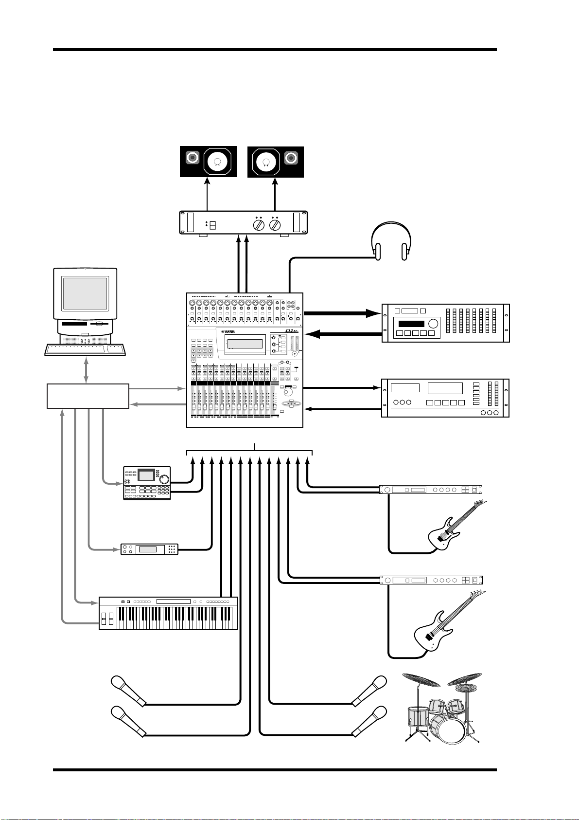
01V System Example
This example shows the kind of system possible with the 01V.
Personal computer
running MIDI software
Monitors
Power Amp
Headphones
Serial port
MIDI
interface
MIDI IN
MIDI IN
MIDI IN
MIDI OUT
Drum machine
Tone generator
MONITOR OUT
OFF
ON
PHANTOM +48V
INPUT (BAL)
PAD
26dB126dB226dB326dB426dB526dB626dB726dB826dB926dB1026dB1126dB
–60–16
–60–16
–60–16
–60–16
–60–16
–60–16
–60–16
+10 –34
+10 –34
+10 –34
+10 –34
GAIN
GAIN
GAIN
GAIN
UTILITY MIDI SETUP VIEW
PAN/
DYNAMICS EQ/ATT Ø/DELAY
ROUTING
FADER MODE
EFFECT 1 EFFECT 2 OPTION I/O REMOTE
AUX 1
AUX 2 AUX 3 AUX 4
HOME
4
3
2
1
17
SEL
SEL
SEL
SEL
SOLO
SOLO
SOLO
SOLO
ON
ON
ON
ON
6
6
6
6
0
0
0
0
5
5
5
5
10
10
10
10
20
20
20
20
40
40
40
40
60
60
60
60
∞
∞
∞
∞
4
3
2
1
17 18 19 20 21 22 23 24
–60–16
+10 –34
+10 –34
+10 –34
+10 –34
GAIN
GAIN
GAIN
GAIN
FUNCTION
MEMORY
1 RETURN 2
10
9
8
7
6
5
232221201918
24
SEL
SEL
SEL
SEL
SEL
SEL
SOLO
SOLO
SOLO
SOLO
SOLO
SOLO
ON
ON
ON
ON
ON
ON
6
6
6
6
6
6
0
0
0
0
0
0
5
5
5
5
5
5
10
10
10
10
10
10
20
20
20
20
20
20
40
40
40
40
40
40
60
60
60
60
60
60
∞
∞
∞
∞
∞
∞
10
9
8
7
6
5
MIC/LINE inputs 1–16
PHONES
OFF
ON
PHANTOM +48V
–10dBV (UNBAL)
131415
L
R
16
IN
OUT
2TR
PHONES
MONITOR
15/16
2TR IN
–60–16
+10 –34
GAIN
11
SEL
SOLO
ON
6
0
5
10
20
40
60
∞
11
2TR IN
–60–16
–60–16
–60–16
–20+10 100 100
–20+10
GAIN
+10 –34
+10 –34
GAIN
13/14
12
SEL
SOLO
ON
6
6
0
0
5
5
10
10
20
20
40
40
60
60
∞
∞
13/14
12
LEVEL LEVELGAIN
+10 –34
GAIN
GAIN
MONITOR
12
13/14 15/16
PHONES
OUT
L STEREO R
EQ
HIGH
CLIP
–3
–6
HI-MID
–9
–12
–15
–18
–24
LO-MID
–30
–36
–42
–48
LOW
1 RETURN 2
SELSEL
SEL
SOLO
SOLO SOLO
ON
MEMORY
–1/DEC
+1/INC
PARAMETER
CURSOR
ENTER
OPTION I/O
OUT
DIGITAL STEREO
COAXIAL
IN
DIGITAL MIXING CONSOLE
PAN
PAN
F
F
G
G
SELECTED CHANNEL
STEREO
15/16
MASTER
SEL
SEL
SOLO
SOLO
ON
ON
ON ON
0
6
–5
0
–10
–15
5
–20
10
–30
–40
20
–50
40
–70
60
– ∞
∞
STEREO
15/16
MASTER
Digital in
Digital out
Digital in
Digital out
Digital multitrack
8-TRACK DIGITAL
DAT recorder
00.00.00.00
DAT
Guitar processor
Bass processor
MIDI IN
MIDI OUT
01V—Owner’s Manual
MIDI keyboard
Vocals Drums
Page 21

Important Wordclock Information 11
Important Wordclock Information
Unlike analog audio equipment, digital audio equipment must be wordclock synchronized when digital audio is transferred from one device to another. See “About Wordclocks” on page 206 for more information.
If the 01V is the only digital audio device in your system, no special wordclock settings
are required, and the 01V synchronizes to its own internal wordclock. Add a D AT
recorder or digital multitrack recorder, however , and the system m ust be configured so
that digital audio equipment synchronizes to a common wor dclock sour c e. The “System Examples” on page 241 show how to configure w ordclock settings with a variety of
digital audio equipment.
Connecting the Power Cord
Warning: Turn off all equipment before making any connections.
Connect the 01V power cor d t o a suitable AC wall outlet, one that conforms to the
power supply requirements stated on the r ear panel of the 01V.
Turning On the 01V
Always turn on your audio equipment in the following order:
1. Sound sources
2. 01V
3. Monitor amplifier
To turn on the 01V, press the 01V POWER switch located on the rear panel.
When turned on, the 01V startup screen appears for a few seconds, and then the display
page selected when the 01V was last turned off appears.
Turning Off the 01V
Always turn off your audio equipment in the following order:
1. Monitor amplifier
2. 01V
3. Sound sources
To turn off the 01V, press the 01V POWER switch located on the rear panel.
All parameter settings, scene memories, and library programs are stored when the 01V
is turned off.
POWER
ON/ OFF
01V—Owner’s Manual
Page 22

12 Chapter 2—Getting Started
01V—Owner’s Manual
Page 23

In this chapter...
Touring the 01V 13
Touring the 01V
3
Top Panel Controls . . . . . . . . . . . . . . . . . . . . . . . . . . . . . . . . . . . . . . . . . . . . . . . . 14
Inputs & Outputs . . . . . . . . . . . . . . . . . . . . . . . . . . . . . . . . . . . . . . . . . . . . . . . . . 20
Block Diagram . . . . . . . . . . . . . . . . . . . . . . . . . . . . . . . . . . . . . . . . . . . . . . . . . . . 24
01V—Owner’s Manual
Page 24
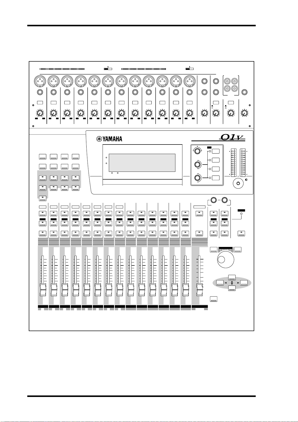
14 Chapter 3—Touring the 01V
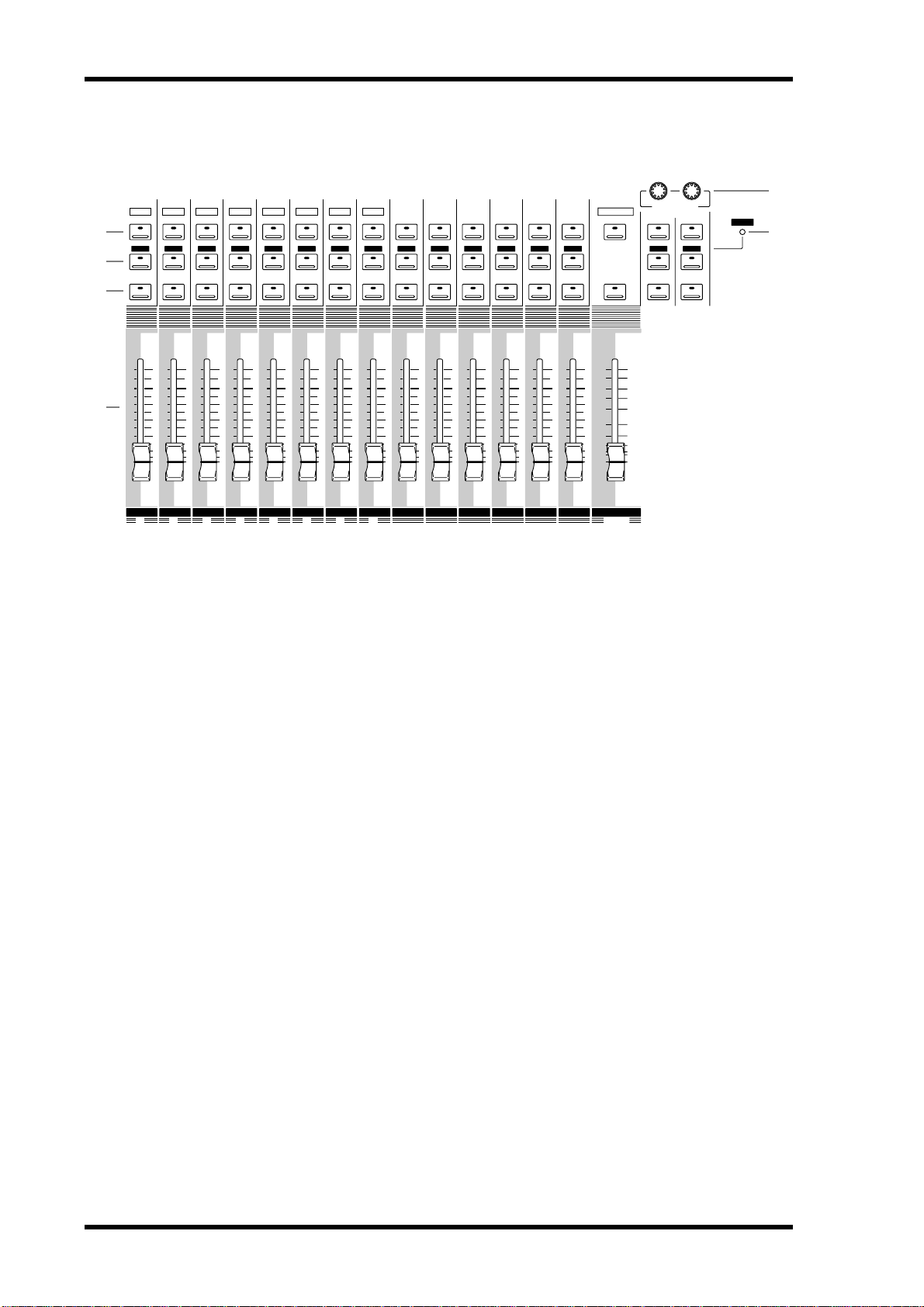
Top Panel Controls
OFF
SEL
ON
INPUT (BAL)
–60–16
–60–16
+10 –34
GAIN
8
24
SEL
–60–16
+10 –34
GAIN
9
SEL
+10 –34
GAIN
1 RETURN 2
7
6
232221201918
SEL
PHANTOM +48V
PAD
26dB126dB226dB326dB426dB526dB626dB726dB826dB
–60–16
+10 –34
+10 –34
GAIN
GAIN
UTILITY MIDI SETUP VIEW
DYNAMICS EQ/ATT Ø/DELAY
FADER MODE
EFFECT 1 EFFECT 2 OPTION I/O REMOTE
AUX 1
AUX 2 AUX 3 AUX 4
HOME
2
1
17
SEL
SEL
–60–16
PAN/
ROUTING
4
SEL
+10 –34
GAIN
–60–16
+10 –34
GAIN
FUNCTION
MEMORY
5
SEL
–60–16
+10 –34
GAIN
3
SEL
OFF
PHANTOM +48V
26dB1026dB1126dB
–60–16
–60–16
+10 –34
GAIN
–60–16
+10 –34
GAIN
+10 –34
GAIN
9
ON
15
16
15/16
2TR IN
–20+10 100 100
–10dBV (UNBAL)
L
R
IN
2TR
MONITOR
2TR IN
LEVEL LEVELGAIN
MONITOR
OUT
OUT
PHONES
PHONES
13
14
–60–16
+10 –34
GAIN
12
–60–16
–20+10
GAIN
13/14 15/16
DIGITAL MIXING CONSOLE
SEL
L STEREO R
CLIP
–3
–6
–9
–12
–15
–18
–24
–30
–36
–42
–48
SOLO
10
SEL
11
SEL
12
SEL
13/14
SEL
EQ
HIGH
SELECTED CHANNEL
STEREO
MASTER
PAN
HI-MID
F
LO-MID
G
LOW
1 RETURN 2
SELSEL
PAN
F
G
15/16
SEL
SOLO
SOLO
SOLO
SOLO
SOLO
SOLO
SOLO
ON
ON
ON
ON
ON
ON
ON
6
6
6
6
6
6
6
0
0
0
0
0
0
0
5
5
5
5
5
5
5
10
10
10
10
10
10
10
20
20
20
20
20
20
20
40
40
40
40
40
40
40
60
∞
1
17 18 19 20 21 22 23 24
60
60
∞
∞
3
2
60
60
∞
∞
5
4
60
60
∞
∞
7
6
The individual sections of the 01V are explained on the following pages.
SOLO
SOLO
SOLO
SOLO
SOLO
SOLO
SOLO
ON
ON
ON
ON
ON
ON
ON
0
6
6
6
6
6
6
6
0
0
0
0
0
0
5
5
5
5
5
5
10
10
10
10
10
10
20
20
20
20
20
20
40
40
40
40
40
40
60
60
∞
∞
9
8
60
60
∞
∞
11
10
60
60
∞
∞
13/14
12
0
5
10
20
40
60
∞
15/16
–5
–10
–15
–20
–30
–40
–50
–70
– ∞
STEREO
MASTER
SOLO SOLO
ON ON
ON
–1/DEC
PARAMETER
ENTER
MEMORY
+1/INC
CURSOR
01V—Owner’s Manual
Page 25

PAD
26dB126dB226dB
–60–16
+10 –34
+10 –34
GAIN
GAIN
Top Panel Controls 15
Analog Control Section
1 2 3
26dB426dB526dB626dB726dB826dB926dB1026dB1126dB
–60–16
–60–16
–60–16
–60–16
–60–16
–60–16
–60–16
–60–16
–60–16
–60–16
+10 –34
+10 –34
+10 –34
+10 –34
+10 –34
+10 –34
+10 –34
+10 –34
GAIN
GAIN
GAIN
GAIN
GAIN
GAIN
GAIN
GAIN
+10 –34
GAIN
3
+10 –34
GAIN
12
–60–16
4 5 6
A PAD switches
These switches are used to turn on and off the 26 dB input pads. See “P ad S witches” on
page 41 for more information.
B 15/16–2TR IN Switch
This switch is used to select the signal source for input channels 15 and 16: phone jacks
15 and 16 (15/16) or the 2TR IN phono jacks (2TR IN).
15/16
2TR IN
–20+10 –20+10 –20+10
–20+10
GAIN
13/14 15/16 PHONES
MONITOR
2TR IN
LEVEL LEVELGAIN
MONITOR
OUT
C MONITOR–2TR IN Switch
This switch is used to select the signal source for the monitor out and phones: M onitor
bus (MONITOR) or 2TR IN phono jacks (2TR IN).
D GAIN controls
These controls are used to adjust the gain of the input preamps. See “Setting Input
Channel Gain” on page 41 for more information.
E MONITOR OUT LEVEL control
This control is used to adjust the monitor out level.
F PHONES LEVEL control
This control is used to adjust the phones level.
01V—Owner’s Manual
Page 26
16 Chapter 3—Touring the 01V
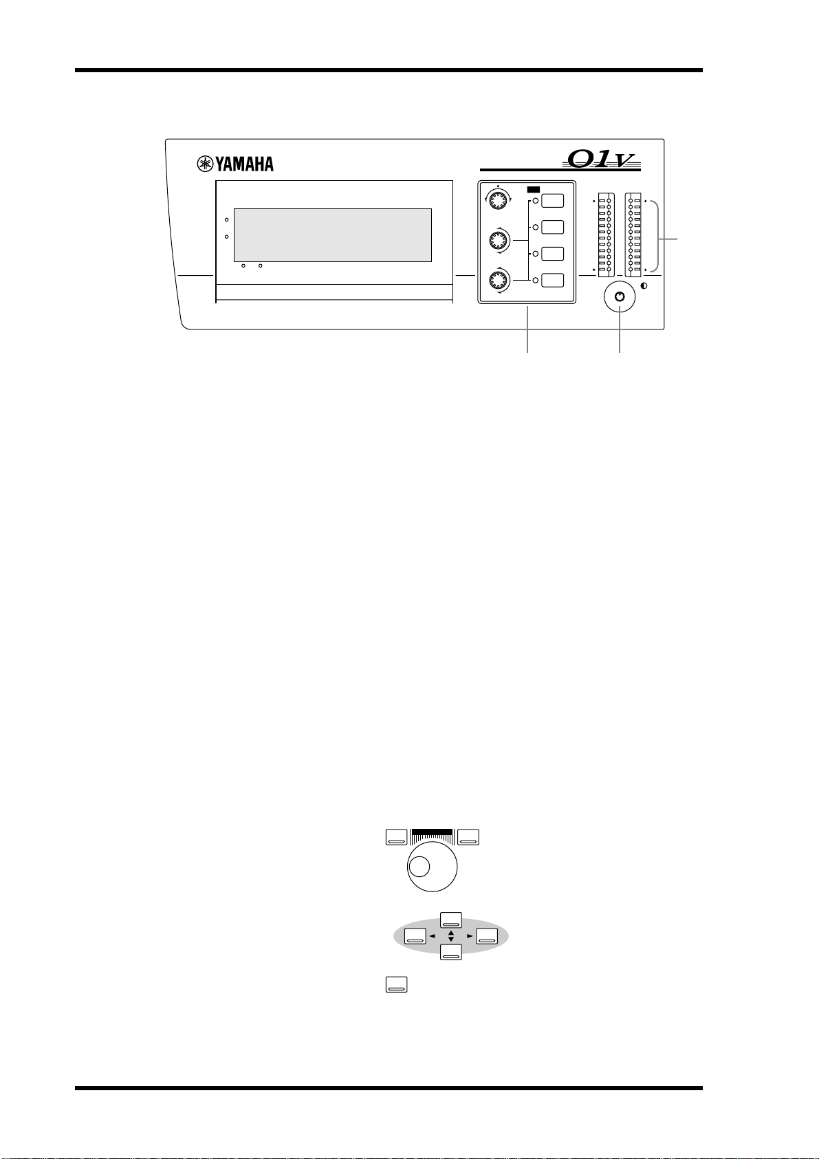
Display, Selected Channel Controls & Meters
DIGITAL MIXING CONSOLE
L STEREO R
CLIP
–3
–6
–9
–12
–15
–18
–24
–30
–36
–42
–48
FUNCTION
MEMORY
1 RETURN 2
1
EQ
HIGH
PAN
PAN
F
G
HI-MID
F
LO-MID
G
LOW
SELECTED CHANNEL
2 3
A Display
This 320 x 80 dot LCD display pr o vides clear indication of mix settings and operating
status. As w ell as showing parameter values numerically, faders and rotary controls are
represented graphically, so you can actually see pan and fader positions. The display
also shows EQ curves and signal level meters. See “Display” on page 28 for more infor mation.
B SELECTED CHANNEL Controls
These controls are used to adjust the pan and EQ of the selected channel. Dedicat ed
rotary controls for PAN, EQ frequency (F) and EQ gain (G), and EQ [HIGH],
[HI-MID], [L O-MID], and [LOW] buttons make for quick operation. When the EQ
AUTO SCREEN option is turned on, and an EQ co ntrol is adjust ed, the EQ page
appears automatically. Likewise, for the PANPOT AUTO SCREEN option and PAN
control. See “Setting 01V Preferences” on page 203 for more information.
4
C Contrast
This control is used to adjust the display c ontrast. Adjust it so that the display is clear
and easy-to-read from your viewing position. You may need to readjust it when viewing
the display from a different height or angle.
D Stereo Output Meters
These 12-segment LED bar-type meters display the stereo output signal levels.
Parameter Wheel, Cursors & Enter
–1/DEC
PARAMETER
ENTER
These controls are used to na vigate ar ound the displa y pages and edit paramet ers. See
“Getting Around the User Interface” on page 27 for mor e information.
+1/INC
CURSOR
01V—Owner’s Manual
Page 27
Top Panel Controls 17
Function Buttons
UTILITY MIDI SETUP VIEW
DYNAMICS EQ/ATT Ø/DELAY
PAN/
ROUTING
Function buttons are used to acc ess the following function pages. Related pages are
grouped together and can be selected by repeatedly pr essing a button. The name of the
selected function and its page number appear in the top-left corner of the display.
Button Pages
UTILITY
MIDI
SETUP
VIEW
DYNAMICS
EQ/ATT
ø/DELAY
PAN/ROUTING
MEMORY
Oscillator, Preferences-1, Preferences-2
MIDI Setup, Program Change, Control Change, Bulk, Local Control
Word Clock Select, Monitor/Solo Setup, Group, Pair, Dither
Channel View, Fader View, CH Copy
Dynamics Edit, Dynamics Library
EQ Edit, EQ Library
Phase, Input Delay 1–8, Input Delay 9–16, Output Delay
Panpot, Routing, Bus Master, Omni Out Select
Memory, Fade Time, Memory Sort, Recall Safe
MEMORY
Fader Mode Buttons
FADER MODE
EFFECT 1 EFFECT 2 OPTION I/O REMOTE
AUX 1
AUX 2 AUX 3 AUX 4
HOME
Fader mode buttons are used to select the following fader modes and display pages.
Pressing buttons repeatedly selects the various pages that are a vailable for a mode. The
name of the selected function and its page number appear in the top-left corner of the
display .
Button Pages
EFFECT 1
EFFECT 2
OPTION I/O
REMOTE
AUX 1
AUX 2
AUX 3
AUX 4
HOME
Effect1 Edit, Effect1 Library, Effect1 Pre/Post
Effect2 Edit, Effect2 Library, Effect2 Pre/Post
Option In Meter, Channel Control, Option Out Meter, Option Out
Select, Input Swap
Internal Parameter, MMC Control, User Define
Pre/Post, Aux 1-2 Pan
Pre/Post, Aux 1-2 Pan
Pre/Post, Aux 3-4 Pan
Pre/Post, Aux 3-4 Pan
Input Meter, Rtn/Output Meter, Omni Out Meter, St Out Meter,
Metering Point
01V—Owner’s Manual
Page 28
18 Chapter 3—Touring the 01V
SEL, SOLO, ON buttons & Faders
1
2
3
4
1
17
SEL
SOLO
ON
6
0
5
10
20
40
60
∞
1
17 18 19 20 21 22 23 24
SEL
SEL
SOLO
SOLO
ON
ON
6
6
0
0
5
5
10
10
20
20
40
40
60
60
∞
∞
3
2
SEL
SEL
SOLO
SOLO
ON
ON
6
6
0
0
5
5
10
10
20
20
40
40
60
60
∞
∞
5
4
232221201918
SEL
SEL
SOLO
SOLO
ON
ON
6
6
0
0
5
5
10
10
20
20
40
40
60
60
∞
∞
7
6
7
6
5
4
3
2
A SEL buttons
The [SEL] buttons are used to select channels for parameter editing: input channels 1
through 24, effects returns 1 and 2, aux sends 1 through 4, effects sends 1 and 2, and the
stereo output. P ress [SEL] button 13/14 or 15/16 r epeatedly to select input channels 13
and 14 or 15 and 16, respectiv ely. Since most functions on input channels 13 and 14
(likewise 15 and 16) are linked together, the only time you’ll need to select either c hannel 13 or channel 14 (likewise 15 or 16) is to set the Phase or Pan for a channel indi vidually . The number of the selected channel appears in the lower-right corner of the
display. See “Display” on page 28 for more information.
5
SOLO
SEL
8
24
SEL
SEL
SEL
SEL
SEL
SEL
MASTER
SEL
1 RETURN 2
SEL SEL
STEREO
15/16
13/14
12
11
10
9
6
SOLO
SOLO
SOLO
SOLO
SOLO
SOLO
SOLO
ON
ON
ON
ON
ON
ON
ON
0
6
6
6
6
6
6
6
0
0
0
0
0
0
5
5
5
5
5
5
10
10
10
10
10
10
20
20
40
40
60
60
∞
∞
9
8
20
20
40
40
60
60
∞
∞
11
10
20
20
40
40
60
60
∞
∞
13/14
12
0
5
10
20
40
60
∞
15/16
–5
–10
–15
–20
–30
–40
–50
–70
– ∞
STEREO
ON
MASTER
SOLO SOLO
ON ON
Normally , [SEL] buttons 1 thr ough 8 select channels 1 through 8. W hen the [OPTION
I/O] button is pressed, ho w ev er, they select input channels 17 through 24, which are
only available when an Option I/O card is installed. See “SEL Buttons” on page 32 for
more information. The [SEL] buttons 1 through 6 are also used to transmit MMC
(MIDI Machine Control) Locate c ommands when REMOTE page 2 is displayed.
Finally , [SEL] buttons are also used to make and br eak c hannel pairs (“Pairing Input
Channels” on page 52) and fader and mute groups (“Grouping F aders” on page 55 and
“Grouping Mutes” on page 56).
B SOLO buttons
The [SOLO] buttons are used t o solo channels: input channels 1 through 16 and effects
returns 1 and 2. No rmally, [SOLO] buttons 1 through 8 select channels 1 through 8.
When the [OPTION I/O] button is pressed, however, they select input channels 17
through 24, which are only a vailable when an Option I/O car d is installed. See “Solo
Buttons” on page 33 for more information.
The [SOLO] buttons 1 through 16 can also be used as MIDI contr ollers on REMOTE
page 3. See “User Defined MIDI Controllers” on page 238 for more information.
C ON buttons
The [ON] buttons are used to turn channels on and off: input channels 1 thr ough 24,
effects returns 1 and 2, aux sends 1 through 4, effects sends 1 and 2, and the ster eo out-
01V—Owner’s Manual
Page 29

Top Panel Controls 19
put. Normally, [ON] buttons 1 through 8 select channels 1 through 8. When the
[OPTION I/O] button is pressed, ho w ev er, they select input channels 17 through 24,
which are only available when an Option I/O card is installed. See “ON Buttons” on
page 34 for more information.
The [ON] buttons 1 through 16 and master can be assigned to various internal parameters on REMOTE page 1, or used as MIDI c ontr ollers on REMOTE page 3. See
“Assigning Faders & On Buttons” on page 194 and “User Defined MIDI Controllers”
on page 238 for more information.
D Faders
Depending on the selected fader mode, the 01V’s 60 mm motorized faders are used to
control channel levels, aux send lev els, or effects sends levels. N o rmally, faders 1
through 8 control channels 1 through 8. When the [OPTION I/O] button is pressed,
however, they control input channels 17 through 24, which are only a vailable when an
Option I/O card is installed. See “F aders (plus Return Rotary Controls)” on page 35 for
more information.
Faders 1 through 16 and master can be assigned to various internal parameters on
REMOTE page 1, or used as MIDI c ontrollers on REMOTE page 3. See “Assigning Faders & On Buttons” on page 194 and “User Defined MIDI Controllers” on page 238 for
more information.
E RETURN Controls
The RETURN controls are used to adjust the effects return levels, and their positions
are displayed in the lowe r-left corner of the display.
F SOLO Status Indicator
The SOLO status indicator lights up when a channel is soloed.
01V—Owner’s Manual
Page 30
20 Chapter 3—Touring the 01V
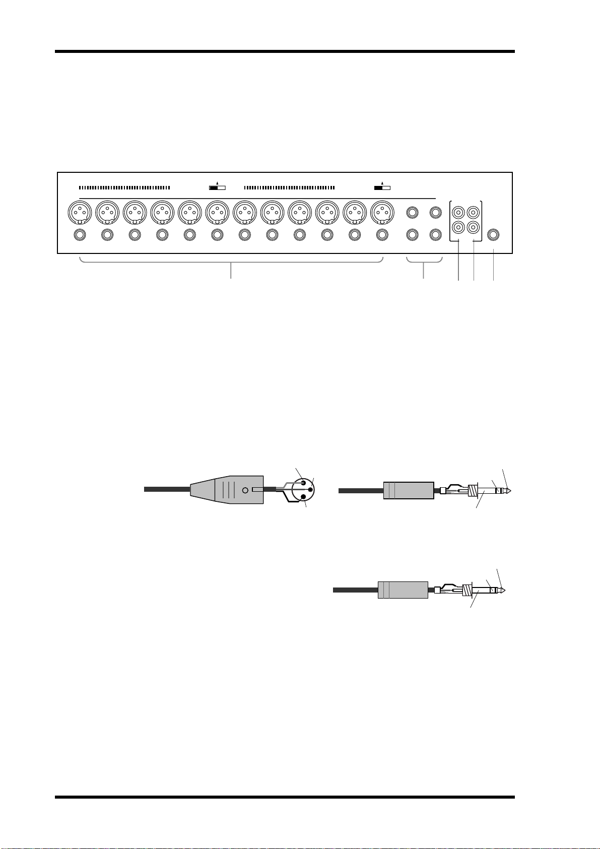
Inputs & Outputs
Input and output connectors are located on the t o p and r ear panels.
Top Panel
PHANTOM +48V
OFF
ON
INPUT (BAL)
PHANTOM +48V
OFF
ON
131415
–10dBV (UNBAL)
L
R
16
IN OUT
2TR
1 2
A INPUT (BAL) 1–12
Input channels 1 through 12 feature balanced XLR -3-31-type and balanced phone jack
connectors, both with a nominal input range of –60 dB to +10 dB. Phantom powering
(+48 V) is supplied to the XLR connectors, with master on/off switches for connectors
1 through 6 and 7 through 12. Phone jacks, whic h can also be used with unbalanced
phone plugs, have priority over the XLR-type connectors, so when a phone plug is
inserted, the XLR -type connector is disconnected. With their high sensitivity and 26 dB
PAD switches, these inputs can handle a wide range of signals, from condenser microphones to “hot ” line levels.
Male XLR plug
1 (ground)
3 (cold)
1/4" TRS phone plug
Ring (cold)
PHONES
534
Tip (hot)
B INPUT (BAL) 13–16
Input channels 13 through 16 feature balanced phone jack connectors, with a
nominal input range of –20 dB to +10 dB.
These inputs are designed for use with
line-level sources, and can also be used
with unbalanced phone plugs. The stereo
outputs of an external effects processor or
other stereo device can be connected here.
2 (hot)
1/4" TRS phone plug
Sleeve (ground)
Tip (hot)
Ring (cold)
Sleeve (ground)
01V—Owner’s Manual
Page 31

C 2TR IN
These are phono jacks with a –10 dBV nominal input level.
Signals input here can be monitored via the monitor out and
phones when the MONITOR–2TR IN switch is set to
2TR IN. The stereo outputs of a master recorder can be connected here for confidence monitoring and master pla yback.
By setting the 15/16–2TR IN switch to 2TR IN, 2TR IN signals can be fed to input channels 15 and 16 for mixing with
other signals.
D 2TR OUT
These are phono jacks with a –10 dBV nominal output level.
The 2TR OUT signal is the same as the stereo out signal. A
cassette deck, D AT, or MiniDisc deck connected here can be
used to record the ster eo mix.
E PHONES
This is a stereo (TRS) phone jack, to
which a pair of stereo headphones can be
connected for monitoring. The phones
signal is the same as the monitor out signal, and the level is set using the phones
level control.
Inputs & Outputs 21
Phono plug
Phono plug
1/4" TRS phone plug
Ring (right)
Sleeve (ground)
Tip
Sleeve
Tip
Sleeve
Tip (left)
01V—Owner’s Manual
Page 32

22 Chapter 3—Touring the 01V
Rear Panel
1 2 3 4 2 65 7 8
PHANTOM +48V
+4dB (BAL)+4dB (BAL)
MONITOR OUT
CH 7-12
ON
OFF ON OFF
OMNI OUT
34LR21
A MONITOR OUT
These are balanced 1/4-inch phone jacks
with a +4 dB nominal output level. Balanced or unbalanced phone plugs can be
connected. They output the monitor signals and should be connected to the inputs
on a monitor amplifier . The monitor signal
source is set using the MONITOR–2TR IN
switch and SETUP page 2, and the output
level is set using the MONITOR LEVEL
control.
CH 1-6
STEREO OUT
+4dB (BAL)
RL
POWER
ON/ OFF
COAXIAL
OUT IN
THRU
OUT IN
OPTION I/O
9 J
1/4" TRS phone plug
TO HOSTMIDIDIGITAL STEREO
Tip (hot)
Ring (cold)
Sleeve (ground)
B PHANTOM +48V ON–OFF Switches
The CH 1–6 and CH 7–12 PHANTOM +48V ON–OFF switches are used to turn on
and off the +48 V phantom power for XLR inputs 1 through 6 and 7 through 12,
respectively.
C OMNI OUTs
These are balanced 1/4-inch phone jacks
with a +4 dB nominal output level. Balanced or unbalanced phone plugs can be
connected. These outputs can be c o nfigured individually as analog bus outs, aux
sends, stereo outs, or direct outs for input
channels 1 through 16. Bus outputs are typically connected to multitrack recor ders,
while aux sends are typically used to feed
external effects processors, foldback amplifiers, and so on.
1/4" TRS phone plug
Tip (hot)
Ring (cold)
Sleeve (ground)
01V—Owner’s Manual
Page 33

Inputs & Outputs 23
D STEREO OUT
These are balanced XLR -3-32-type
connectors with a +4 dB nominal
Female XLR plug
output level. They are wired pin
1–ground, pin 2–hot (+), and pin
3–cold (–). They output the main stereo mix.
If you need to connect the balanced ST OUT to an unbalanced phone jack input, use a
cable with the following wiring scheme (i.e., XLR pins 3 and 1 linked).
Tip (hot)
1/4" phone plug
Female XLR plug
2 (hot)
2 (hot)
3 (cold)
1 (ground)
3 (cold)
Sleeve (ground)
E DIGITAL STEREO OUT
This phono jack outputs the main stereo mix as Coaxial format 24-bit digital audio,
allowing digital transfer to a DAT, MiniDisc deck, or other digital recorder .
F DIGITAL STEREO IN
This phono jack accepts 24-bit Coaxial format digital audio. S ignals input here can be
fed directly to the Stereo bus for ster eo cascade operation (i.e., two mixers working
together), or to input channels 13 and 14.
G MIDI IN, OUT, THRU
These are standard MIDI IN, OUT, and THR U ports and are used t o c onnect the 01V
to other MIDI equipment for remote control and data backup. The MIDI IN port
receives MIDI messages, while the MIDI OUT port transmits them. The MIDI THRU
port transmits all MIDI messages received at the MIDI IN port.
H TO HOST
This 8-pin mini DIN port is used to connect the 01V to a personal computer for use
with MIDI software. It eliminates the need for a co mputer MIDI interface, and t ogether
with the MIDI ports allows the 01V to be used as a MIDI interface for other MIDI
equipment.
I POWER switch
This switch is used to turn on and off the 01V. It’s r ec essed t o pr ev ent ac cidental operation.
1 (ground)
J OPTION I/O slot
An Option I/O card can be installed here, pr o viding acc ess t o the 01V’s eight digital
inputs and outputs. See “A bout Option I/O Car ds” on page 216.
01V—Owner’s Manual
Page 34

24 Chapter 3—Touring the 01V
Block Diagram
LR
OUT
MONI
OUTPUT
SELECT
to
Meter
L
2TR OUT
R
L
DA
Delay
OUT
STEREO
R
DA
Delay
DIGITAL
STEREO
Dither
STEREO OUT
LISTEN
Meter
BUS
SELECT
OUTPUT
to
1-4
1-4
LISTEN
Meter
AUX
OUTPUT
SELECT
to
1-4
1-4
LISTEN
ST CASCADE IN
LISTEN
to
MONITOR
to INTERNAL
EFFECT 1, 2
ST
EFF
AUX
BUS
Meter
RL
121234
4321
Meter
PAN
CH Fader
Delay
Dynamics
PEQ
4-Band
AUX1
ON
BALANCE
AUX2
ON
AUX3
Dynamics
PEQ
4-Band
AUX4
EFF1
EFF2
AUX/EFF
PRE/POST
SELECT
OUTPUT
to
Meter
CH Fader
Delay
ON
BUS
master fader
TO ST
Meter
PAN
AUX3
AUX4
EFF1
AUX2
AUX1
PAN*
ON
Delay
AUX
master fader
Meter
Meter
EFF2
ON
Dynamics
PEQ
4-Band
AUX/EFF
PRE/POST
OUTPUT
SELECT
to
DIGITAL
to MONI
ON/OFF
STEREO
IN
from
to MONI
master fader
Effect send 1/2
Same as INPUT 13
ON
*PAN: INDIVIDUAL/GANG/INV. GANG
Same as INPUT 14
Meter
Dynamics
PEQ
4-Band
ATT
+48V
AD
PHANTOM
7-12
1-6,
to
INPUT
(BAL)
GAIN
HA
Pad
26dB
1-12
01V—Owner’s Manual
Meter
Dynamics
PEQ
4-Band
HA AD
13
ATT
GAIN
INPUT
(BAL)
Dynamics
PEQ
4-Band
HA AD
14
FLIP
De-emphasis
DIGITAL
STEREO
IN
Meter
4-Band
AD
HA
15
PEQ
ATT
15/16
GAIN
INPUT
2TR IN
(BAL)
PEQ
4-Band
AD
HA
16
from 2TR IN
Page 35

1-8
OUT
Option I/O
OMNI
Block Diagram 25
OUT
MONITOR
R
L
OUT
1-4
PHONES
STEFFAUX
BUS
RL
121234
4321
Meter
STEREO L
STEREO R
BUS 1
Meter
Option I/O
BUS 4
AUX 1
PAN
I/O
Option
Select
Output
from
Meter
Dither
AUX 4
AUX1
CH 1
CH 2
AUX2
Meter
EFF1
CH 15
CH 16
EFF2
AUX/EFF
PRE/POST
BUS 1
STEREO L
STEREO R
LEVEL
DA
Delay
Select
OMNI OUT
BUS 4
AUX 1
AUX 4
CH 1
CH 2
CH 15
CH 16
from
AUX3
AUX4
EFF2
AUX/EFF
PRE/POST
AUX1
PAN*
AUX2
from
MONI
MONITOR
2TR IN
EFF1
DA
DA
MONO
TRIM
MONI
to INPUT 15, 16
LEVEL
R
L
2TR IN
Meter
Unchanged
Unchanged
1-8
INPUT
(BAL)
SWAP
CH Fader
Meter
De-emphasis
PEQ
2-Band
or DC Cut
IN
Option I/O
17-24
Rotary
EFF RTN
ON
Meter
ATT
This section is available only when
an optional Option I/O card is installed.
Meter
PEQ
4-Band
from EFF1
ON
Internal
Effect 1
PEQ
4-Band
Meter
Same as Effect 1
Internal
from EFF2
Effect 2
OSC
ON
LEVEL
100Hz
1kHz
10kHz
Waveform
PINK
*PAN: INDIVIDUAL/GANG/INV. GANG
BURST
01V—Owner’s Manual
Page 36

26 Chapter 3—Touring the 01V
01V—Owner’s Manual
Page 37

Getting Around the User Interface 27
Getting Around the User Interface
4
In this chapter...
About the User I nt e rfac e . . . . . . . . . . . . . . . . . . . . . . . . . . . . . . . . . . . . . . . . . . . 28
Display . . . . . . . . . . . . . . . . . . . . . . . . . . . . . . . . . . . . . . . . . . . . . . . . . . . . . . . . . . 28
Display Elements . . . . . . . . . . . . . . . . . . . . . . . . . . . . . . . . . . . . . . . . . . . . . . . . . . 30
Cursor Buttons . . . . . . . . . . . . . . . . . . . . . . . . . . . . . . . . . . . . . . . . . . . . . . . . . . . 31
PARAMETER Wheel . . . . . . . . . . . . . . . . . . . . . . . . . . . . . . . . . . . . . . . . . . . . . . 31
–1/DEC & +1/INC Buttons . . . . . . . . . . . . . . . . . . . . . . . . . . . . . . . . . . . . . . . . . 31
ENTER Button . . . . . . . . . . . . . . . . . . . . . . . . . . . . . . . . . . . . . . . . . . . . . . . . . . . 31
Fader Modes . . . . . . . . . . . . . . . . . . . . . . . . . . . . . . . . . . . . . . . . . . . . . . . . . . . . . 32
Title Edit Dialog Box . . . . . . . . . . . . . . . . . . . . . . . . . . . . . . . . . . . . . . . . . . . . . . 37
01V—Owner’s Manual
Page 38

28 Chapter 4—Getting Around the User Interface
About the User Interface
Thanks to a user-friendly interface, 01V operation is both logical and intuitive. The 320
x 80 dot LCD display pr o vides clear indication of mix settings and operating status,
while dedicated SELECTED CHANNEL controls allow for quick EQ and pan adjustments. Operation of the multifunction faders depends on the selected Fader mode.
Mixing functions and configuration settings are organized into display pages, with up
to five related pages being grouped together . For example, the MIDI Setup and P rogram
Change pages are grouped together under MIDI. P arameter selection and editing is carried out using the [CURSOR], [ENTER], [–1/DEC] and [+1/INC] butto ns, and
PARAMETER wheel, which is detent ed for pr ecise and ac curate editing.
Display
The 320 x 80 dot LCD display pr o vides clear indication of mix settings and operating
status. As w ell as showing parameter values numerically, faders and rotary controls are
represented graphically, so you can actually see pan and fader positions. The display
also shows EQ curves and signal level meters. The various sections of the display are
explained below .
Page area
Function
Memory
Effects
Returns
Selected channel
Function—This area of the display shows the name of the function
selected using the Function and Fader mode buttons. Functions are
divided into pages, which are identified b y n umber ed tabs, as shown
here. In this example, page 1 of the VIEW function is select ed. The following functions can be selected.
Function Buttons Fader Mode Buttons
UTILITY EFFECT 1
MIDI EFFECT 2
SETUP OPTION I/O
VIEW REMOTE
DYNAMICS AUX 1
EQ/ATT AUX 2
ø/DELAY AUX 3
PAN/ROUTING AUX 4
MEMORY HOME
01V—Owner’s Manual
Page 39

Display 29
Memory—This area of the display shows the number and title of the
selected scene memory, whether that scene memory is read only or write
protected (indicated by the closed padlock ic on), and whether or not the
contents of the Edit Buffer have been edited. See “ Sc ene Memory Display Area” on page 185 for more information. Also in the M emory area
are the MIDI and HOST indicators, which appear when MIDI data is
received at the MIDI IN or TO HOST port, respectively. See “MIDI
Receive I ndicat ors ” on page 224 for more information.
Effects Returns—This area of the display shows two control icons,
which indicate the positions of the RETURN level controls, and the type
of effects selected for the two onboard effects processors: Effect 1 and
Effect 2. When the EFFECT 1 or EFFECT 2 Fader mode is selected, the
corresponding control icon is highlighted.
Selected channel—This area of the display shows three control ic ons:
Pan, EQ fr equency (F), and EQ gain (G), which indicate the pan, EQ frequency , and EQ gain of the selected channel. Below these is the selected
channel indicator, showing which channel is currently selected. The following channels can be selected.
CH1 through CH24—Input channels 1 through 24
•
ST—Ster eo output
•
RTN1, RTN2—Effects returns 1 and 2
•
AUX1 through AUX4—Aux sends 1 through 4
•
EFF1, EFF2—Effects sends 1 and 2
•
1–16, MAS—Remote function channels
•
When channels 13 through 16, the effects return channels, or paired input
channels from 1 through 12 are selected, dotted lines appear to the right
of these control icons when an odd or left channel is selected. Similarly,
dotted lines appear to the left, as sho wn here, when an even or right channel is selected.
Page area—This area of the display is where the various setup, utility, and mixing
function pages appear. As well as showing parameter values numerically, faders and
rotary controls are represented graphically, so you can actually see pan and fader positions. See “Display Elements” on page 30 for more information. A n e xample page is
shown below .
01V—Owner’s Manual
Page 40

30 Chapter 4—Getting Around the User Interface
Nominal
Display Elements
This section explains the various control elements that appear on display pages.
Switches
Switches appear as box es with a shadowed outline (i.e., a thick er outline on the right side and bottom).
Simple on/off-type switches are highlighted when they are turned
on. In this example, the [ST] switch is on.
The labels inside some switches change when they turned on and
off, as these phase switches show.
For option-type switches, only one switch can be on at a time. In this
example, the monitor sourc e can be set t o either st er eo out or ST
CASCADE IN, but not both.
To operate a switch, use the cursor buttons to select it, and the [ENTER] button or
[–1/DEC] and [+1/INC] buttons to turn it on or off.
Rotary Controls
Some parameters appear as rotary controls, as this example fr om
the P ANPO T page shows. To adjust a rotary control, use the cursor
buttons to select it and use the PARAMETER wheel or [–1/DEC]
and [+1/INC] buttons to adjust it.
Parameter Boxes
Some parameters appear in parameter boxes
(i.e., dotted-line bo xes), as this example from
the EFFECT1 EDIT page shows. To adjust a
parameter box parameter, use the cursor buttons to select it, and the PARAMETER wheel or
[–1/DEC] and [+1/INC] buttons to set it.
Parameter bo xes that require you to c o nfirm
new settings flash until you press the [ENTER]
button.
Faders
01V—Owner’s Manual
Pages such as VIEW and BUS MASTER display faders graphically . To adjust a fader , use the cursor buttons to select it, and the
PARAMETER wheel or [–1/DEC] and [+1/INC] buttons to set
it. Fader knobs appear highlighted when set to the nominal position.
Page 41

Cursor Buttons
Cursor Buttons 31
The cursor buttons are used to move the cursor
around the display pages, selecting parameters and
options. The cursor appears as a flashing box, making
it easy to see which parameter or option is currently
selected. Holding down a cursor button moves the
cursor continuously in the respectiv e dir ection.
PARAMETER Wheel
The P ARAMETER wheel is used t o adjust parameter values, scroll
through scene memory and library programs, and position the
cursor when titling scene memories, effects programs, and so on.
Its detented action gives it a positiv e feel, allo wing quick and accurate parameter editing. Turning it clockwise increases parameter
values; turning it counterclockwise decreases them.
–1/DEC & +1/INC Buttons
Like the P ARAMETER wheel, the [–1/DEC] and [+1/INC]
buttons are used to adjust parameter values, scroll through
scene memory and library programs, and position the cursor when titling scene memories, effects programs, and so
on. The [–1/DEC] button is used to decrement values, while the [+1/INC] button is
used to increment them. H olding down the [–1/DEC] or [+1/INC] button sweeps
through a parameter’s adjustable range. When titling memories or programs, the
[–1/DEC] button is used to toggle between uppercase, lo we r case, and numerals, while
the [+1/INC] button is used to insert spaces.
–1/DEC +1/INC
PARAMETER
CURSOR
PARAMETER
ENTER Button
The [ENTER] button is used to activate parameter settings selected using
the [CURSOR] buttons, and set on/off-type parameters, such as EQ
ON/OFF . It ’ s also used to confirm settings and enter characte rs when titling
scene memories, effects programs, and so on. On the EQ page, the [ENTER] button is
used solely to turn the EQ on and off.
ENTER
01V—Owner’s Manual
Page 42

32 Chapter 4—Getting Around the User Interface
Fader Modes
The 01V [SEL], [SOL O], and [ON] buttons, channel faders, and STEREO (MASTER)
fader are multifunction controls, and their exact operation depends on the selected
Fader mode. Operation of these controls is shown in the following tables.
SEL Buttons
The [SEL] buttons are used to select channels for EQ, Pan, Dynamics, and Routing
operations. The following channels can be selected:
CH1 through CH24—Input channels 1 through 24
•
ST—Ster eo output
•
RTN1, RTN2—Effects returns 1 and 2
•
AUX1 through AUX4—Aux sends 1 through 4
•
EFF1, EFF2—Effects sends 1 and 2
•
1–16, MAS—Remote function channels
•
The [SEL] buttons are also used to make and r elease channel pairs and fader and mute
groups (“Grouping Faders ” on page 55 and “Grouping Mutes ” on page 56).
Fader Mode
HOME
AUX 1
AUX 2
AUX 3
AUX 4
EFFECT 1
EFFECT 2
OPTION I/O
REMOTE 1
REMOTE 2
REMOTE 3
*1. CH17–20 with four-input Option I/O cards.
1–8
[17–24]
CH 17–24
select
MMC (1–6) —
9–12 13/14
CH 1–16 select
*1
— — STEREO select
Internal parameter assign select —
User defined MIDI controller select —
SEL button
15/16
STEREO
[MASTER]
STEREO OUT
select
AUX 1
master select
AUX 2
master select
AUX 3
master select
AUX 4
master select
EFFECT 1
master select
EFFECT 2
master select
RETURN 1/2
RETURN 1/2
select
01V—Owner’s Manual
Input Channel [SEL] button Examples
T o select the EQ function for input channel 3, press the [HOME] button, and then press
[SEL] button 3 (CH3 appears in the bottom right corner of the display). Use the
SELECTED CHANNEL F and G controls to adjust the EQ. (If a fader mode other than
Option I/O or Remote is selected, it’ s not nec essary to press the [HOME] butt on.)
To select the Pan function for input channel 13, press the [HOME] butt on, and then
press [SEL] button 13/14 repeatedly until CH13 appears on the displa y. Use the
SELECTED CHANNEL P AN c ontrol t o adjust the pan. Sinc e most functions on input
Page 43

Fader Modes 33
channels 13 and 14 (likewise 15 and 16) are linked, the only time you’ll need to select
these channels individually is to set the Phase or Pan. (If a fader mode other than
Option I/O or Remote is selected, it’ s not nec essary to press the [HOME] butt on.)
To select the EQ function for input channel 20, press the [OPTION I/O] button, and
then press [SEL] button 20 (CH20 appears on the display). U se the F and G controls t o
adjust the EQ.
Master [SEL] Button Examples
To select the stereo output, press the [HOME] button, and then press the MASTER
[SEL] button (ST appears in the bottom right corner of the display).
To select the A UX 1 master, press the [AUX 1] button, and then press the MASTER
[SEL] button (AUX1 appears on the display).
To select the EFFECT 1 master , press the [EFFECT 1] button, and then press the MASTER [SEL] button (EFF1 appears on the display).
Solo Buttons
The [SOLO] buttons are used t o solo channels for monit oring. See “Solo Setup” on
page 80 for more information. The following channels can be soloed:
CH1 through CH24—Input channels 1 through 24
•
RTN1, RTN2—Effects returns 1 and 2
•
SOLO button
Fader Mode
HOME
AUX 1
AUX 2
AUX 3
AUX 4
EFFECT 1
EFFECT 2
OPTION I/O
REMOTE 1
REMOTE 2
REMOTE 3
*1. CH17–20 with four-input Option I/O cards.
1–8
[17–24]
CH 17–24
solo
User defined MIDI controller —
9–12 13/14
CH 1–16 solo
*1
———
15/16
—
—
RETURN 1/2
RETURN 1/2
solo
The [SOLO] buttons 1 through 16 can be used as MIDI contr ollers on REMO TE page
3. See “User Defined MIDI Controllers” on page 238 for more information.
Usage Examples
To solo input channel 3, press the [HOME] button, and then pr ess [SOLO] button 3.
(If a fader mode other than Option I/O or Remote is selected, it ’ s not necessary to press
the [HOME] button.)
T o solo input channels 13/14, press the [HOME] button, and then press [SOLO] button
13/14. (If a fader mode other than Option I/O or Remote is selected, it’s not necessary
to press the [HOME] button.)
To solo input channel 20, press the [OPTION I/O] button, and then pr ess [SOL O] button 20.
01V—Owner’s Manual
Page 44

34 Chapter 4—Getting Around the User Interface
ON Buttons
The [ON] buttons are used to turn channels on or off. They work with the following
channels:
CH1 through CH24—Input channels 1 through 24
•
ST—Ster eo output
•
RTN1, RTN2—Effects returns 1 and 2
•
AUX1 through AUX4—Aux sends 1 through 4
•
EFF1, EFF2—Effects sends 1 and 2
•
The bus outs can be turned on or off on PAN/R OUT page 4.
Fader Mode
HOME
AUX 1
AUX 2
AUX 3
AUX 4
EFFECT 1
EFFECT 2
OPTION I/O
REMOTE 1
REMOTE 2
REMOTE 3
*1. CH17–20 with four-input Option I/O cards.
1–8
[17–24]
CH 1–16 On/Off
CH 17–24
On/Off
MMC (1–6) —
*1
Assigned internal parameters —
User defined MIDI controllers —
ON button
9–12 13/14
15/16
master On/Off
master On/Off
master On/Off
master On/Off
master On/Off
master On/Off
——
STEREO
[MASTER]
STEREO OUT
On/Off
AUX 1
AUX 2
AUX 3
AUX 4
EFFECT 1
EFFECT 2
STEREO OUT
On/Off
RETURN 1/2
RETURN 1/2
On/Off
01V—Owner’s Manual
On buttons 1 through 16 and master can be assigned to various internal parameters on
REMOTE page 1, or used as MIDI c ontrollers on REMOTE page 3. See “Assigning Faders & On Buttons” on page 194 and “User Defined MIDI Controllers” on page 238 for
more information.
Input Channel [ON] button Examples
To turn on or off input channel 3, press the [HOME] button, and then press [ON] button 3. (If a fader mode other than Option I/O or Remote is select ed, it’s not necessary
to press the [HOME] button.)
T o turn on or off input channels 13/14, pr ess the [HOME] button, and then press [ON]
button 13/14. (If a fader mode other than Option I/O or Remote is select ed, it’ s not necessary to press the [HOME] button.)
To turn on or off input channel 20, pr ess the [OPTION I/O] butt on, and then press
[ON] button 20.
Master [ON] Button Examples
To turn on or off the stereo output, press the [HOME] button, and then use the MASTER [ON] button.
Page 45

Fader Modes 35
To turn on or off the AUX 1 send master, pr ess the [AUX 1] button, and then use the
MASTER [ON] button.
To turn on or off the EFFECT 1 send master, press the [EFFECT 1] button, and then
use the MASTER [ON] button.
Faders (plus Return Rotary Controls)
The faders are used to adjust channel levels.
Fader Rotary Control
Fader Mode
HOME
AUX 1
AUX 2
AUX 3
AUX 4
EFFECT 1
EFFECT 2
OPTION I/O
REMOTE 1
REMOTE 2
REMOTE 3
*1. Effects return 1 cannot be fed to effect send 1
*2. Effects return 2 cannot be fed to effect send 2
*3. CH17–20 with four-input Option I/O cards.
1–8
[17–24]
CH 1–16 AUX 1 send level
CH 1–16 AUX 2 send level
CH 1–16 AUX 3 send level
CH 1–16 AUX 4 send level
CH 1–16 EFFECT 1 send level
CH 1–16 EFFECT 2 send level
CH 17–24
level
9–12 13/14
CH 1–16 level
*3
——
Assigned internal parameters —
User defined MIDI controllers —
15/16
—
STEREO
[MASTER]
STEREO
master level
AUX 1
master level
AUX 2
master level
AUX 3
master level
AUX 4
master level
EFFECT 1
master level
EFFECT 2
master level
STEREO
master level
RETURN 1/2
RETURN 1/2 levels
RETURN 1/2 AUX
1 send levels
RETURN 1/2 AUX
2 send levels
RETURN 1/2 AUX
3 send levels
RETURN 1/2 AUX
4 send levels
RETURN 1 level
*1
RETURN 2 EFFECT
1 send level
*2
RETURN 1 EFFECT
2 send level
RETURN 2 level
RETURN 1/2 levels
Faders 1 through 16 and master can be assigned to various internal parameters on
REMOTE page 1, or used as MIDI c ontrollers on REMOTE page 3. See “Assigning Faders & On Buttons” on page 194 and “User Defined MIDI Controllers” on page 238 for
more information.
Input Channel Level Examples
T o adjust the level of input channel 3, pr ess the [HOME] button, and then operate fader
3.
To adjust the level of input channel 13/14, press the [HOME] button, and then operate
fader 13/14.
To adjust the level of input channel 20, press the [OPTION I/O] button, and then oper-
ate fader 20.
Input Channel Aux Send Examples
To adjust the aux 1 send level of input channel 3, press the [A UX 1] butt on, and then
operate fader 3.
01V—Owner’s Manual
Page 46

36 Chapter 4—Getting Around the User Interface
To adjust the aux 1 send level of input channel 13/14, press the [A UX 1] butt on, and
then operate fader 13/14.
To adjust the aux 1 send level of input channel 20, use the [OPTION I/O] button to
locate OPTION page 2, press [SEL] button 20, use the cursor buttons to select the
AUX 1 fader, and then adjust it using the PARAMETER wheel or [–1/DEC] and
[+1/INC] buttons.
Note: A ux send levels for input channels 17 through 24 can only be set using the virtual
faders on OPTION page 2.
Input Channel Effects Send Examples
To adjust the Effect 1 send level of input channel 3, press the [EFFECT 1] button, and
then operate fader 3.
To adjust the Effect 1 send level of input channel 13/14, press the [EFFECT 1] button,
and then operate fader 13/14.
To adjust the Effect 1 send level of input channel 20, use the [OPTION I/O] button to
locate OPTION page 2, press [SEL] button 20, use the cursor buttons to select the
EFFECT 1 fader, and then adjust it using the PARAMETER wheel or [–1/DEC] and
[+1/INC] buttons.
Note: Effects send levels for input channels 17 through 24 can only be set using the
virtual faders on OPTION page 2.
Master Level Examples
To adjust the level of stereo out, press the [HOME] button, and then operate the MASTER fader.
To adjust the A UX 1 master send level, pr ess the [AUX 1] button, and then operate the
MASTER fader.
To adjust the EFFECT 1 master send level, press the [EFFECT 1] button, and then
operate the MASTER fader.
To adjust the BUS OUT 1 master send level, use the [PAN/ROUT] button to locate
P AN/R OUT page 3, use the cursor buttons to select the BUS 1 fader, and then adjust it
using the PARAMETER wheel or [–1/DEC] and [+1/INC] buttons.
Note: Bus out master levels can only be set using the virtual faders on PAN/ROUT
page 3.
01V—Owner’s Manual
Page 47

Title Edit Dialog Box 37
Title Edit Dialog Box
The Title Edit dialog box is used to title mix sc enes, EQ pr ograms, dynamics pr ograms,
and effects programs. Program titles can be up to 12 characters, scene memory titles up
to 8 characters.
1. Use the cursor buttons to position the cursor in the title window.
2. Use the PARAMETER wheel to select characters.
3. Use the cursor buttons to select the following switches, and press the
[ENTER] button to execute their functions.
INS—Insert a space at the cursor position and moves subsequent characters to the
right. Characters moved beyond the right edge of the title window are lost.
DEL—Delete the character at the cursor position and move subsequent characters t o
the left.
4. Use the [+1/INC] button to enter a space at the cursor position.
5. Use the [–1/DEC] button to toggle the character at the cursor position
between uppercase, lowercase, and numerals.
6. Press the [ENTER] button to store.
01V—Owner’s Manual
Page 48

38 Chapter 4—Getting Around the User Interface
01V—Owner’s Manual
Page 49

In this chapter...
Input Channels 39
Input Channels
5
Input Channel Overview . . . . . . . . . . . . . . . . . . . . . . . . . . . . . . . . . . . . . . . . . . . 40
Phantom Powering . . . . . . . . . . . . . . . . . . . . . . . . . . . . . . . . . . . . . . . . . . . . . . . . 41
Pad S witches . . . . . . . . . . . . . . . . . . . . . . . . . . . . . . . . . . . . . . . . . . . . . . . . . . . . . 41
Setting Input Channel Gain . . . . . . . . . . . . . . . . . . . . . . . . . . . . . . . . . . . . . . . . . 41
Metering Input Channels . . . . . . . . . . . . . . . . . . . . . . . . . . . . . . . . . . . . . . . . . . . 41
Changing the Input Phase . . . . . . . . . . . . . . . . . . . . . . . . . . . . . . . . . . . . . . . . . . 42
Attenuating Input Channel S ignals . . . . . . . . . . . . . . . . . . . . . . . . . . . . . . . . . . 43
Applying EQ to Input Channels . . . . . . . . . . . . . . . . . . . . . . . . . . . . . . . . . . . . . 44
Input Channels Dynamics Processors . . . . . . . . . . . . . . . . . . . . . . . . . . . . . . . . 44
Delaying Channel Signals . . . . . . . . . . . . . . . . . . . . . . . . . . . . . . . . . . . . . . . . . . 45
Muting Input Channels . . . . . . . . . . . . . . . . . . . . . . . . . . . . . . . . . . . . . . . . . . . . 46
Setting Input Channel Levels . . . . . . . . . . . . . . . . . . . . . . . . . . . . . . . . . . . . . . . . 46
Panning Input Channels . . . . . . . . . . . . . . . . . . . . . . . . . . . . . . . . . . . . . . . . . . . 47
Routing Input Channels . . . . . . . . . . . . . . . . . . . . . . . . . . . . . . . . . . . . . . . . . . . 49
Monitoring Input Channels . . . . . . . . . . . . . . . . . . . . . . . . . . . . . . . . . . . . . . . . 50
Input Channels & Aux Sends . . . . . . . . . . . . . . . . . . . . . . . . . . . . . . . . . . . . . . . 50
Input Channels & the Omni Outs . . . . . . . . . . . . . . . . . . . . . . . . . . . . . . . . . . . 50
Input Channels & the Option I/O Outs . . . . . . . . . . . . . . . . . . . . . . . . . . . . . . . 50
Swapping Inputs 1–8 & 17–24 . . . . . . . . . . . . . . . . . . . . . . . . . . . . . . . . . . . . . . 51
Pairing Input Channels . . . . . . . . . . . . . . . . . . . . . . . . . . . . . . . . . . . . . . . . . . . . 52
Grouping Faders . . . . . . . . . . . . . . . . . . . . . . . . . . . . . . . . . . . . . . . . . . . . . . . . . . 55
Grouping M ut es . . . . . . . . . . . . . . . . . . . . . . . . . . . . . . . . . . . . . . . . . . . . . . . . . . 56
Viewing Input Channel Settings . . . . . . . . . . . . . . . . . . . . . . . . . . . . . . . . . . . . . 57
Copying & Swapping Channel Settings . . . . . . . . . . . . . . . . . . . . . . . . . . . . . . . 59
Input Channel Block Diagram . . . . . . . . . . . . . . . . . . . . . . . . . . . . . . . . . . . . . . 60
01V—Owner’s Manual
Page 50

40 Chapter 5—Input Channels
Input Channel Overview
This section provides an overview of 01V input channels.
Input Channels 1–12
3
1
2
XLR INPUT
(balanced)
XLR-3-31-type and balanced phone jack connectors, both
with a nominal input range of –60 dB to +10 dB. Phantom
powering (+48 V) is supplied to the XLR c onnect ors, with
master on/off switches for connectors 1 through 6 and 7
Input channels 1 through 12 feature balanced
Phone jack INPUT
(balanced)
through 12. Phone jacks, which can also be used with
unbalanced phone plugs, hav e priority over the XLR-type
connectors, so when a phone plug is inserted, the XLR -type
connector is disconnected. Inputs 1 through 8 can be
swapped with inputs 17 through 24. See “Swapping Inputs
1–8 & 17–24” on page 51 for mor e information.
Input Channels 13–16
13
14
Phone jacks INPUT
(balanced)
15
16
Apart from being stereo, input channels 13/14 and 15/16
offer the same features as input channels 1 through 12. N ormally , the input signals for input channels 13 and 14 are
derived from phone jack inputs 13 and 14. B y using the
CH13-14 FLIP function on PAN/ROUT page 4, however,
the DIGIT AL STEREO IN signals can be fed to input c hannels 13 and 14. See “Digital Stereo I n ” on page 213 for more
information. Similarly, the input signals for input channels
15 and 16 are normally derived from phone jack inputs 15
and 16. By using the 15/16–2TR IN switch, however, the
2TR IN signals can be fed to input channels 15 and 16. See
“Two-track Input (2TR IN)” on page 77 for more information.
01V—Owner’s Manual
Input Channels 17–24
OPTION I/O
Input channels 17 through 24 do not have analog input
connectors, a pad switch, gain control, or direct out. They
are somewhat simpler than input channels 1 through 16 in
that they feature only an attenuator, two-band parametric
EQ, and can be assigned to aux sends 1 and 2, but not aux
sends 3 and 4. Input channels 17 through 24 are accessed
through the digital inputs of the Option I/O slot. See “About
Option I/O Cards” on page 216 for more information.
Inputs 17 through 24 can be swapped with inputs 1 through
8. See “ Swapping I nputs 1–8 & 17–24” on page 51 for mor e
information.
Page 51

Phantom Powering
Phantom Powering 41
CH 1-6
ON OFF
Input channels 1 through 12 feature +48 V phant om po w ering for use with
condenser-type microphones. Phantom powering is supplied to the balanced XLR-3-31-type connector , and can be switched for inputs 1 through 6
and inputs 7 through 12. Phantom pow ering should be turned on only when
CH 7-12
ON OFF
a condenser-type microphone is connected.
W arning: Make sure that phantom pow ering is turned off when connecting an unbalanced source to an XLR input.
Pad Switches
Input channels 1 through 12 feature 26 dB pad switches. Input pads att enu-
26dB
ate the input signal by 26 dB, allo wing the input preamp to work with
high-level signals. You may need to use a pad with “hot” signals fr om bass or
snare drum microphones, or “hot” line-level signals. P AD switch settings are
not stored in scene memories.
Setting Input Channel Gain
GAIN controls adjust the gain of the input channel preamps. They’ re used to optimiz e
the input signal level for the best signal-to-noise performance, and should be set in conjunction with the level meters on the HOME pages. Ideally, the GAIN control should
be set so that the signal level is relatively high, and it ’s okay for it to reach CLIP occasionally . If CLIP is reached often, however , back off the GAIN control a little, otherwise,
signal distortion may occur . The GAIN control should be set with care. If it’ s set too low,
the signal-to-noise performance will suffer. If it’s set too high, unpleasant signal clipping and distortion may occur.
The GAIN controls on input channels 1 through 12 are designed for use
with microphone signals, and have an input sensitivity of –16 dB to
–60 dB. Used in conjunction with the 26 dB PAD switches, howev e r,
–60–16
+10 –34
GAIN
these channels can also be used with line-level signals and “hot” microphone signals. W ith the pad switch on, input sensitivity is +10 to –34 dB.
A detented action allows for accurate r epeat setting.
The GAIN controls on input channels 13 through 16 are designed for use
with line-level signals, and have a gain range of –10 dB to 20 dB.
–20+10
GAIN
GAIN control settings are not stored in sc ene memories.
Metering Input Channels
Signal levels can be metered on the HOME pages. See “Metering Signal Levels” on page
83 for more information.
01V—Owner’s Manual
Page 52

42 Chapter 5—Input Channels
Changing the Input Phase
The Phase switches, available on input channels 1 thr ough 16, reverse the phase of input
signals by 180 degrees. This can be used to compensat e for inc orrectly wired balanc ed
cables and microphones. Also, when a snare drum is miked to p and bott om, the channel connected to the bottom microphone can be phase r ev e rsed t o pr ev ent signal cancellation.
1. Use the [∅/DELAY] button to locate DELAY page 1, as shown below.
2. Use [SEL] buttons 1 through 16 to select channels.
Phase switches can also be selected using the cursor buttons.
3. Use the [ENTER] button, or the [–1/DEC] and [+1/INC] buttons to set the
phase of the selected channel to normal or reversed.
Normal phase
Reversed phase
The Phase switches on input channels 13 and 14 (likewise 15 and 16) are not linked, and
can be set independently . W hen input channels 1 through 12 are paired (“P airing Input
Channels” on page 52), their Phase switches continue to w o rk independently.
Input channels 17 through 24 do not have Phase switches.
01V—Owner’s Manual
Page 53

Attenuating Input Channel Signals 43
Attenuating Input Channel Signals
Input channels 1 through 24 are fitted with digital attenuators, whic h can be used t o
attenuate input signals from 0 dB to –96 dB in 1 dB steps.
For Input Channels 1–16
1. Use the [EQ/ATT] button to locate EQ page 1, as shown below.
2. Use [SEL] buttons 1 through 16 to select channels.
3. Use the cursor buttons to select the ATT control, and the PARAMETER
wheel or [–1/DEC] and [+1/INC] buttons to adjust it.
The Attenuation functions on input c hannels 13 and 14 (likewise 15 and 16) are permanently linked. When input channels 1 through 12 are paired (“Pairing Input Channels” on page 52), their attenuat ors are link ed, so adjustments can be made with either
channel selected.
The Atten uation function can be used t o c ompensat e for signal level incr eases caused
by EQ boosting or dynamics processing. Although such signals can be reduced using
the GAIN controls, doing so w ould ad v ersely affect the performanc e of the A/D converters, which need a reasonable signal level in or der t o maximiz e signal-to-noise performance. Since the digital attenuat ors ar e locat ed aft er A/D conversion, they can be
used to attenuate signals without affecting performance.
For Input Channels 17–24
1. Use the [OPTION I/O] button to locate OPTION page 2.
2. Use [SEL] buttons 17 through 24 to select channels.
3. Use the cursor buttons to select the ATT control, and the PARAMETER
wheel or [–1/DEC] and [+1/INC] buttons to adjust it.
01V—Owner’s Manual
Page 54

44 Chapter 5—Input Channels
Applying EQ to Input Channels
Input channels 1 through 16 feature four-band parametric EQ, while input c hannels 17
through 24 feature two-band parametric EQ. See “EQ” on page 61 for more information. EQ can be turned on or off and the EQ curve viewed on the EQ page and VIEW
page. See “Viewing Input Channel Settings” on page 57 for more information.
Input Channels Dynamics Processors
Input channels 1 through 16 feature a dynamics proc essor. See “Dynamics Pr ocessors ”
on page 161 for more information. The dynamics can be turned on or off and the
dynamics curve viewed on the Dynamics page and VIEW page. See “ Viewing Input
Channel Settings” on page 57 for mor e information.
01V—Owner’s Manual
Page 55

Delaying Channel Signals 45
Delaying Channel Signals
The Channel Delays, a vailable on input channels 1 through 16, can be used to compensate for microphone placement, or simply as delay effects. The delay parameters for
input channels 1 through 8 are on DELAY page 2, while those for input channels 9
though 16 are on DELAY page 3. Both pages are shown below.
1. Use the [∅/DELA Y] button to locate DELA Y page 2 or 3, as shown below.
2. Use the [SEL] buttons to select channels.
3. Use the cursor buttons to select the delay parameters and the [ENTER]
button, PARAMETER wheel, or [–1/DEC] and [+1/INC] buttons to set
them.
Parameter Range Description
ON/OFF
DELAY
MIX
FB. GAIN
ON/OFF These switches are used to turn on and off the delays.
Delay can be specified in milliseconds, meters, or samples
(“Setting 01V Preferences” on page 203). The maximum
0–250 ms
–100 to +100
–99 to +99
delay in samples is fixed at 11025. The maximum delay in
milliseconds and meters depends on the sampling rate. At
44.1 kHz, for example, it is 250 milliseconds and 85.2
meters, respectively.
This parameter determines the level of delayed signal. 0 is
no delay. +50 is a 50/50 mix of delayed and dry signals.
+100 is all delay, no dry. Negative values are the same
except the delayed signal is phase reversed.
This parameter determines how much of the delayed signal is fed back into the delay. 0 is no feedback. +99 is
maximum feedback. Negative values are the same except
the feedback signal is phase reversed.
The Channel Delays on input channels 13 and 14 (likewise 15 and 16) are permanently
linked. When input channels 1 through 12 are paired (“Pairing Input Channels” on
page 52), their Channel Delays are linked, so adjustments can be made with either
channel selected.
01V—Owner’s Manual
Page 56

46 Chapter 5—Input Channels
Muting Input Channels
Input channels can be turned on and off (i.e., muted) using the [ON] buttons.
ON
When a channel is on, its [ON] butt on lights up .
To turn on or off an input channel from 1 thr ough 16, select a fader mode
other than Option I/O or Remote, and then pr ess an [ON] butt on fr om 1
through 16.
To turn on or off an input channel from 17 thr ough 24, press the [OPTION
I/O] button, and then press an [ON] button from 17 through 24.
The [ON] buttons on input channels 13 and 14 (likewise 15 and 16) are permanently linked. When input channels 1 through 12 are paired (“Pairing
Input Channels” on page 52), their [ON] buttons are linked.
ON buttons can be grouped together for multi-channel muting using a single
[ON] button. See “Grouping Mutes” on page 56 for more information.
Setting Input Channel Levels
Input channel levels are controlled using the mot o rized 60 mm faders.
6
0
5
T o adjust the level of an input channel from 1 through 16, press the [HOME]
button, and then operate a fader from 1 thr ough 16.
To adjust the level of an input channel from 17 through 24, press the
[OPTION I/O] button, and then operate a fader from 17 thr ough 24.
10
20
40
60
Faders operation depends on the selected Fader mode. See “Faders (plus
Return Rotary Controls)” on page 35 for more information. The selected
fader mode is shown on the display . See “Display” on page 28 for more infor mation.
∞
The faders on input channels 13 and 14 (likewise 15 and 16) are permanently
linked. W hen input channels 1 thr ough 12 are paired (“Pairing Input Channels” on page 52), their faders are linked.
Faders can be grouped together for multi-channel control using a single
fader. See “Grouping Faders” on page 55 for more information.
01V—Owner’s Manual
Page 57

Panning Input Channels 47
Panning Input Channels
The Panpots, available on input channels 1 through 24 (and the effects returns), are
used to pan signals between the left and right channels of the stereo out, and the odd
and even bus outs. Panpots can be adjusted using the SELECTED CHANNEL PAN
control, the quick est method, or the panpot pages in conjunction with the cursor buttons, [–/DEC] and [+/INC] buttons, and PARAMETER wheel.
EQ
HIGH
For quick panning, select
a channel and use the
PAN control.
For Input Channels 1–16 & the Effects Returns
1. Use the [SEL] buttons to select channels.
To select input channel 13 or 14 (likewise 15 or 16), press [SEL] button 13/14 (15/16)
repeatedly. The number of the currently selected channel appears on the display. To
select the left or right channel of effects return 1 (likewise effects return 2), press [SEL]
button RETURN 1 (RETURN 2) repeatedly. As these channels are selected, the lett er
“R” or “L” appears on the display next to the panpot ic on.
PAN
HI-MID
F
LO-MID
G
LOW
SELECTED CHANNEL
2. Use the PAN control to pan the selected channel.
If the PANPOT AUTO SCREEN option is turned on in the preferences (“Setting 01V
Preferences ” on page 203), the P AN/ROUT page shown below appears, and the H ome
fader mode is selected. This page can also be located using the [PAN/ROUTING] button.
Panpots can be adjusted on this page by using the PARAMETER wheel or [–1/DEC]
and [+1/INC] buttons. In addition to the [SEL] butt ons, panpots on the PAN/ROUT
page can be selected using the cursor buttons.
For Input Channels 17–24
1. Press the [OPTION I/O] button.
2. Use [SEL] buttons 17 through 24 to select channels.
3. Use the PAN control to pan the selected channel.
If the PANPOT AUTO SCREEN option is turned on in the preferences (“Setting 01V
Preferences ” on page 203), the OPTION page shown below appears. This page can also
01V—Owner’s Manual
Page 58

48 Chapter 5—Input Channels
be located using the [OPTION I/O] button.
Panpots can also be adjusted on this page by using the cursor butt ons to select the PAN
control and the PARAMETER wheel or [–1/DEC] and [+1/INC] buttons to set it.
Including center, there are 33 pan positions.
Hard left
L16←···←L3←L2←L1←CENTER→R1→R2→R3→···→R16
Center
Hard right
Input channels 1 through 12 and 17 through 24 feature a single panpot, as
shown here.
Input channels 13/14 and 15/16 (and the effects returns) feature dual panpots, with the inner panpots being odd-numbered channel pans 13 and 15
(effects returns left), and the outer panpots being even-numbered channel
pans 14 and 16 (effects returns right). When w orking with stereo signals,
these dual panpots can be used to adjust the width of stereo signals, as
shown below .
With the inner control set at L16 and the out er contr ol set at R16, as sho wn
here, the width of a stereo signal is 100%.
With both controls set at CENTER, as shown here, the width of the stereo
signal is zero (i.e., mono).
Setting the controls to positions in between these two extr emes allo ws you
to set the width of the stereo signal. To maintain a central balance, however,
you must set both controls to c o rresponding values. For example, L8 and
R8, or L10 and R10.
1. Use the cursor buttons to select the MODE parameter, and the PARAM-
01V—Owner’s Manual
Pan Modes
The three Pan modes, INDIVIDU AL, GANG, and INV. GANG, determine how the
panpots operate on input channels 13/14, 15/16 (and the effects returns), and paired
input channels 1 through 12. Since input c hannels 17 through 24 cannot be paired, they
are not affected by the P an modes.
ETER wheel or [–1/DEC] and [+1/INC] buttons to select a mode.
INDIVIDUAL—In this mode, panpots function independently.
GANG—In this mode, panpots are ganged (i.e., linked) together.
INV. GANG—In this mode, panpots are ganged t ogether but operation is
inverted (i.e., panpots mo ve in opposite directions).
Page 59

Routing Input Channels 49
Routing Input Channels
The Routing switches, a vailable on input channels 1 through 24 (and the effects
returns), are used to r out e signals to the four bus outs, stereo out, and dir ect outs.
For Input Channels 1–16 & the Effects Returns
1. Use the [PAN/ROUTING] button to locate PAN/ROUT page 2, as shown
below.
2. Use the [SEL] buttons to select channels.
3. Use the cursor buttons to select the Routing switches and the [ENTER]
button to set them.
For Input Channels 17–24
1. Use the [OPTION I/O] button to locate OPTION page 2, as shown below .
2. Use [SEL] buttons 17 through 24 to select channels.
3. Use the cursor buttons to select the Routing switches and the [ENTER]
button to set them.
A highlighted Routing switch indicates that a channel has been routed.
Input channels 1 through 12 have four bus out r outing switches (1, 2, 3, 4), a
stereo out routing switch (ST), and a dir ect out r outing switch (D). The latt er
switch is turned on automatically when an input channel is selected as the
source for an Option I/O out on OPTION page 4. Lik ewise, when an input
channel is selected as the source for an Option I/O out on OPTION page 4, the
corresponding D switch on the PAN/ROUT page is turned on. See “Assigning
Option I/O Digital Outputs” on page 219 for mor e information.
Input channels 13 through 24 (and the effects returns) have four bus out r outing switches (1, 2, 3, 4) and a stereo out routing switch (ST).
Routing switches work in conjunction with Panpots t o feed signals thr ough to the left
and right channels of the stereo out and the odd and even bus outs. The following table
01V—Owner’s Manual
Page 60

50 Chapter 5—Input Channels
shows how it works.
Routing Pan Signal Destination
The Routing switches on input channels 13 and 14 (likewise 15 and 16) are permanently linked. When input channels 1 thr ough 12 are paired (“P airing Input Channels”
on page 52), their Routing switches are not linked.
Monitoring Input Channels
Input channels can be monitored using the monitor out or phones. See “Monitor
Setup” on page 78 for more information.
Signals are fed equally to bus outs 1 and 2 and the left and right
channels of the stereo out.
Signals are fed to bus out 1 and the left channel of the stereo
out.
Signals are fed to bus out 2 and the right channel of the stereo
out.
Input Channels & Aux Sends
Signals from input channels 1 through 16 can be sent to aux sends 1 through 4, while
those from input channels 17 through 24 can be sent to aux sends 1 and 2. Input channel sends can be configured as either pre-fader or post-fader sends. When aux sends ar e
paired, aux send panpots become a vailable on eac h input channel. See “Aux Sends” on
page 93 for more information.
Input Channels & the Omni Outs
Direct signals from input channels 1 through 16 can be selected for the omni outs. See
“Omni Outs” on page 115 for more information. Note that OMNI OUTs are not
affected by the D switches on the PAN/ROUT page 2.
Input Channels & the Option I/O Outs
Input channels 1 through 16 can be selected as sources for the Option I/O outs. See
“Routing Input Channels” on page 49 and “About Option I/O Cards” on page 216 for
more information.
01V—Owner’s Manual
Page 61

Swapping Inputs 1–8 & 17–24 51
Swapping Inputs 1–8 & 17–24
The inputs to channels 1 through 8 can be swapped with those of input channels 17
through 24 either individually or altogether . This allows signals from the Option I/O
digital inputs to make use of the 4-band EQ, dynamics processors, and other functions
of full-feature input channels 1 through 8.
1. Use the [OPTION I/O] button to locate OPTION page 5, as shown below .
2. Use the cursor buttons to select the GLOBAL or individual SWAP switches,
and the [ENTER] button, PARAMETER wheel, or [–1/DEC] and [+1/INC]
buttons to set them.
Swap switches appear highlighted when channels are swapped.
When channels are swapped, their meter n umbers appear highlighted on HOME page
1 and OPTION page 1, as shown below. When a swapped channel is selected, the
selected channel area of the display alternately shows the channel number and “SW AP”,
also shown below.
01V—Owner’s Manual
Page 62

52 Chapter 5—Input Channels
Pairing Input Channels
Input channels 1 through 12 can be paired together for stereo signal pr oc essing. Adjacent odd and even input channels can be paired together (i.e., 1/2, 3/4, 5/6, not 2/3 or
4/5). The following parameters are linked when c hannels ar e pair ed: att en uat ors, EQ,
dynamics, delays, [ON], and [SEL] buttons, faders, aux sends, effects sends, and
pre/post settings. Routing switches, [SOL O] buttons, phase, panpots, aux panpots, and
fade time on/off are not linked. P anpot operation depends on the selected Pan mode.
See “Pan Modes” on page 48 for more information.
Making Input Channel Pairs
1. Press the [SEL] button of both input channels simultaneously.
OR
Use the [SETUP] button to locate SETUP page 4, as shown below , and use
the cursor buttons to select channel pairs, and then press the [ENTER]
button.
The following dialog box appears.
CH 1 –> 2—Copy the settings of input channel 1 to input channel 2.
CH 2 –> 1—Copy the settings of input channel 2 to input channel 1.
RESET BOTH—Reset both input channels to their initial settings.
2. Use the cursor buttons to select a pairing mode, and then press the
[ENTER] button.
The highlighted switch and STEREO label show that the input
channels are now configur ed as a st er eo pair.
01V—Owner’s Manual
Page 63

Pairing Input Channels 53
Releasing Input Channel Pairs
1. Press the [SEL] button of both input channels simultaneously.
OR
On SETUP page 4, use the cursor buttons to select the paired channel
switch, and then press the [ENTER] button.
The following dialog box appears.
2. Select OK, and then press the [ENTER] button.
The stereo pair is broken, and both input channels operate independently.
01V—Owner’s Manual
Page 64

54 Chapter 5—Input Channels
Input Channel Pair Block Diagram
LR
432121
AUX EFF ST
BUS
1234
PAN*
AUX1
AUX2
EFF1
EFF2
AUX/EFF
PRE/POST
*PAN: INDIVIDUAL/GANG/INV. GANG
CH Fader
Meter
Delay
Dynamics
PEQ
4-Band
Unchanged
ON
ATT
CH Fader
Meter
Delay
Dynamics
PEQ
4-Band
Unchanged
01V—Owner’s Manual
CH INPUT 1, 3...11
(odd channels)
CH INPUT 2, 4...12
(even channels)
Page 65

Grouping Faders 55
Grouping Faders
Input channel faders 1 through 16 can be grouped together in fader groups for
multi-channel control using a single fader. Three groups are available: A, B , and C.
Making Fader Groups
1. Use the [SETUP] button to locate SETUP page 3, as shown below.
2. Use the up and down cursor buttons to select the fader groups, and the
[SEL] buttons to add and remove faders to and from that group.
Channels cannot be in more than one group at a time.
Input channels 13/14, 15/16, and paired input channels 1 through 12 (“Pairing Input
Channels” on page 52) are added and removed together.
Operate only one fader in a group at a time. If you attempt to adjust two or mor e faders
in the same group, the fader mot ors may malfunction due to the increased load.
Enabling & Disabling Fader Groups
Fader groups can be enabled and disabled using the ENABLE switches. Disabling a
group allows you to adjust faders without removing them from the group.
1. Use the up and down cursor buttons to select the fader group that you
want to disable: A, B, or C.
2. Use the [ENTER] button, PARAMETER wheel, or [–1/DEC] and [+1/INC]
buttons to enable or disable the selected group.
Fader group enabled
Fader group disabled
01V—Owner’s Manual
Page 66

56 Chapter 5—Input Channels
Grouping Mutes
Input channel [ON] buttons 1 through 16 can be grouped together in mute groups for
multi-channel control using a single button. Thr ee groups ar e available: D, E, and F.
Mute groups may contain on channels and off channels, making it easy to toggle
between channels. When switched, on channels go off and off channels come on.
Making a Mute Group
1. Use the [SETUP] button to locate SETUP page 3, as shown below.
2. Use the up and down cursor buttons to select the mute groups, and the
[SEL] buttons to add and remove channels to and from that group.
Channels cannot be in more than one group at a time.
Input channels 13/14, 15/16, and paired input channels 1 through 12 (“Pairing Input
Channels” on page 52) are added and removed together.
Enabling & Disabling Mute Groups
Mute groups can be enabled and disabled using the ENABLE switches. Disabling a
group allows you to set channels without remo ving them from the group.
1. Use the up and down cursor buttons to select the mute group that you
want to disable: D, E, or F.
2. Use the [ENTER] button, PARAMETER wheel, or [–1/DEC] and [+1/INC]
buttons to enable or disable the selected group.
Mute group enabled
Mute group disabled
01V—Owner’s Manual
Page 67

Viewing Input Channel Settings 57
Viewing Input Channel Settings
Settings for input channels 1 through 16 can be viewed, and certain parameters
adjusted on VIEW pages 1 and 2. Settings for input channels 17 through 24 can be
viewed and adjusted on OPTION page 2.
Input Channels 1–16
1. Use the [VIEW] button to locate VIEW page 1 or 2
VIEW pages for input channels 1 through 12 appear as below.
VIEW pages for input channels 13/14 and 15/16 appear as below.
2. Use [SEL] buttons 1 through 16 to select channels.
3. Use the cursor buttons to select the parameters, and the PARAMETER
wheel, [–1/DEC], [+1/INC], and [ENTER] buttons to set them.
01V—Owner’s Manual
Page 68

58 Chapter 5—Input Channels
Input Channels 17–24
1. Use the [OPTION I/O] button to locate OPTION page 2, as shown below .
2. Use [SEL] buttons 17 through 24 to select channels.
3. Use the cursor buttons to select the parameters, and the PARAMETER
wheel, [–1/DEC], [+1/INC], and [ENTER] buttons to set them.
Most of the parameters for input channels 17 through 24 can be set only on OPTION
page 2.
01V—Owner’s Manual
Page 69

Copying & Swapping Channel Settings 59
Copying & Swapping Channel Settings
The Channel Copy function is used to copy input c hannel settings from one channel to
another. The Channel swap function is used to swap input channel settings between
channels. Copy and Swap can be used with input channels 1 through 16.
1. Use the [VIEW] button to locate the VIEW page shown below.
2. Use the cursor buttons and PARAMETER wheel to select the SOURCE and
DESTINATION channels.
3. Use the cursor buttons and [ENTER] button to select a CATEGORY.
ALL—All input channel settings.
EQ—EQ settings.
DELAY—Delay settings.
DYNAMICS—Dynamics settings.
FADER—Fader settings.
4. Use the cursor buttons to select COPY or SWAP, and the [ENTER] button
to execute the function.
01V—Owner’s Manual
Page 70

60 Chapter 5—Input Channels
Input Channel Block Diagram
1-6,
INPUT
(BAL)
1-12
Pad
26dB
to
7-12
PHANTOM
HA
GAIN
+48V
AD
ATT
4-Band
PEQ
Meter
Dynamics
Meter
Delay
Meter
AUX
BUS
4321
CH Fader
ON
PAN
AUX/EFF
PRE/POST
OUTPUT
to
SELECT
AUX1
AUX2
AUX3
AUX4
EFF1
EFF2
EFF
121234
ST
RL
13
INPUT
(BAL)
14
DIGITAL
STEREO
IN
15
INPUT
(BAL)
16
GAIN
De-emphasis
GAIN
HA AD
HA AD
HA
HA
Pad
Pad
15/16
2TR IN
Meter
4-Band
Dynamics
PEQ
ATT
4-Band
Dynamics
PEQ
FLIP
Meter
ATT
4-Band
PEQ
4-Band
PEQ
AD
AD
Delay
Delay
Same as INPUT 13
Same as INPUT 14
CH Fader
ON
AUX/EFF
PRE/POST
ON/OFF
to
PAN*
AUX1
AUX2
AUX3
AUX4
EFF1
EFF2
OUTPUT
SELECT
to MONI
to MONI
INPUT
1-8
(BAL)
Option I/O
17-24
IN
Thissectionisavailableonlywhen
anoptionalOptionI/Ocardisinstalled.
Unchanged
De-emphasis
or DC Cut
01V—Owner’s Manual
from 2TR IN
SWAP
Meter
Meter
ATT
2-Band
PEQ
Unchanged
CH Fader
ON
AUX/EFF
PRE/POST
*PAN: INDIVIDUAL/GANG/INV. GANG
PAN
AUX1
AUX2
EFF1
EFF2
Page 71

In this chapter...
EQ 61
EQ
6
About the 01V EQ . . . . . . . . . . . . . . . . . . . . . . . . . . . . . . . . . . . . . . . . . . . . . . . . 62
Adjusting the EQ . . . . . . . . . . . . . . . . . . . . . . . . . . . . . . . . . . . . . . . . . . . . . . . . . . 63
EQ Specs . . . . . . . . . . . . . . . . . . . . . . . . . . . . . . . . . . . . . . . . . . . . . . . . . . . . . . . . 66
Bypassing the EQ . . . . . . . . . . . . . . . . . . . . . . . . . . . . . . . . . . . . . . . . . . . . . . . . . 66
Resetting the EQ . . . . . . . . . . . . . . . . . . . . . . . . . . . . . . . . . . . . . . . . . . . . . . . . . . 66
EQ Library . . . . . . . . . . . . . . . . . . . . . . . . . . . . . . . . . . . . . . . . . . . . . . . . . . . . . . . 67
Preset EQ Pr ogram List . . . . . . . . . . . . . . . . . . . . . . . . . . . . . . . . . . . . . . . . . . . . 67
Storing EQ Programs . . . . . . . . . . . . . . . . . . . . . . . . . . . . . . . . . . . . . . . . . . . . . . 68
Recalling EQ Programs . . . . . . . . . . . . . . . . . . . . . . . . . . . . . . . . . . . . . . . . . . . . 69
Editing EQ Program Titles . . . . . . . . . . . . . . . . . . . . . . . . . . . . . . . . . . . . . . . . . 70
Preset EQ Pr ogram P aramete rs . . . . . . . . . . . . . . . . . . . . . . . . . . . . . . . . . . . . . . 71
01V—Owner’s Manual
Page 72

62 Chapter 6—EQ
About the 01V EQ
Input channels 1 through 16, the effects returns, aux sends, and stereo out all featur e
four-band parametric EQ, with variable gain, frequency, Q, and ON/OFF parameters.
Input channels 17 through 24 feature a simplified two-band parametric EQ. See the
“Block Diagram” on page 24 for the exact location of each EQ section. The high and
low bands of each EQ can be used as shelving, peaking, or HPF (High-Pass Filt er) and
LPF (Low-Pass Filter), respectively.
EQ settings can be stored in the EQ library as programs, or with all mix settings in mix
scenes. The EQ library consists of 40 preset programs and 40 user programs. User pr ograms allow you to store frequently used EQ settings, whic h can be titled for easy identification. The unique collection of preset EQ programs are designed for specific
applications and instruments, and provide a good referenc e and starting point when
making EQ adjustments. The EQ library cannot be used with the 2-band EQs on input
channels 17 through 24. See “EQ Library” on page 67 for mor e information.
The EQs on input channels 13 and 14 (likewise 15 and 16) are permanently linked.
When input channels 1 through 12 are paired (“Pairing Input Channels” on page 52),
their EQs are linked.
The EQ parameters and response curve for input channels 1 through 16, the effects
returns, aux sends, and stereo out appear on the EQ page shown below.
The EQ parameters and response curve for input channels 17 through 24 appear on the
OPTION page shown below.
The quickest way to adjust the EQ is by using the SELECTED CHANNEL c o ntrols
shown below .
EQ
HIGH
PAN
HI-MID
F
LO-MID
G
LOW
SELECTED CHANNEL
01V—Owner’s Manual
Page 73

Adjusting the EQ 63
Adjusting the EQ
EQ can be adjusted using the SELECTED CHANNEL controls, the quickest method, or
the EQ pages in conjunction with the cursor buttons, [–/DEC] and [+/INC] buttons,
and PARAMETER wheel.
EQ
HIGH
PAN
HI-MID
F
For quick EQ'ing select
a channel and use the
EQ controls.
For Input Channels 1–16
1. Use [SEL] buttons 1 through 16 to select channels.
2. Use the [HIGH], [HI-MID], [LO-MID], and [LOW] buttons to select EQ
bands, and the F and G controls to adjust the frequency and gain, respectively .
LO-MID
G
LOW
SELECTED CHANNEL
If the EQ A UTO SCREEN option is turned on in the preferenc es (“Setting 01V Preferences” on page 203), the EQ page shown below appears, and the Home fader mode is
selected. This page can also be located using the [EQ/ATT] button.
The EQ can also be adjusted on this page by using the cursor buttons to select parameters and the PARAMETER wheel or [–1/DEC] and [+1/INC] buttons to set them.
For Input Channels 17–24
1. Press the [OPTION I/O] button.
2. Use [SEL] buttons 17 through 24 to select channels.
3. Use the [HIGH] and [LOW] buttons to select EQ bands, and the F and G
controls to adjust the frequency and gain, respectively.
If the EQ A UTO SCREEN option is turned on in the preferenc es (“Setting 01V Preferences” on page 203), the OPTION page shown below appears. This page can also be
located using the [OPTION I/O] button.
01V—Owner’s Manual
Page 74

64 Chapter 6—EQ
The EQ can also be adjusted on this page by using the cursor buttons to select parameters and the PARAMETER wheel or [–1/DEC] and [+1/INC] buttons to set them.
For Effects Returns 1 & 2
1. Use the effects returns [SEL] buttons to select effects returns 1 and 2.
2. Use the [HIGH], [HI-MID], [LO-MID], and [LOW] buttons to select EQ
bands, and the F and G controls to adjust the frequency and gain, respectively .
If the EQ A UTO SCREEN option is turned on in the preferenc es (“Setting 01V Preferences” on page 203), the EQ page shown below appears, and the Home fader mode is
selected. This page can also be located using the [EQ/ATT] button.
The EQ can also be adjusted on this page by using the cursor buttons to select parameters and the PARAMETER wheel or [–1/DEC] and [+1/INC] buttons to set them.
For Aux Sends 1–4
1. Use the Fader Mode AUX buttons to select an aux send.
2. Press the MASTER [SEL] button.
3. Use the [HIGH], [HI-MID], [LO-MID], and [LOW] buttons to select EQ
bands, and the F and G controls to adjust the frequency and gain, respectively .
If the EQ A UTO SCREEN option is turned on in the preferenc es (“Setting 01V Preferences” on page 203), the EQ page shown below appears, and the Home fader mode is
selected. This page can also be located using the [EQ/ATT] button.
01V—Owner’s Manual
The EQ can also be adjusted on this page by using the cursor buttons to select parameters and the PARAMETER wheel or [–1/DEC] and [+1/INC] buttons to set them.
When aux sends are paired (“Pairing Aux Sends” on page 101), their EQs are link ed.
Page 75

Adjusting the EQ 65
For the Stereo Output
1. Press the [HOME] button.
2. Press the MASTER [SEL] button.
ST is the selected channel.
3. Use the [HIGH], [HI-MID], [LO-MID], and [LOW] buttons to select EQ
bands, and the F and G controls to adjust the frequency and gain, respectively .
If the EQ A UTO SCREEN option is turned on in the preferenc es (“Setting 01V Preferences” on page 203), the EQ page shown below appears, and the Home fader mode is
selected. This page can also be located using the [EQ/ATT] button.
The EQ can also be adjusted on this page by using the cursor buttons to select parameters and the PARAMETER wheel or [–1/DEC] and [+1/INC] buttons to set them.
01V—Owner’s Manual
Page 76

66 Chapter 6—EQ
EQ Specs
The following table contains the EQ specs.
Gain (G)
Frequency (F)
Q
1. Four-band EQs only (low and high bands only on input channels 17 through 24).
2. When the low and high EQ bands are configured as HPF and LPF, their gain controls
Bypassing the EQ
The selected channel’ s EQ can be turned on or off using the EQ ON switch on
the EQ page (OPTION page 2 for channels 17 through 24), or the [ENTER]
button. While the EQ page is display ed, the [ENTER] button turns the EQ on
or off regardless of the cursor position.
Low
21 Hz–20.1 kHz (1/12 octave steps, 120 steps)
HPF, 10.0–0.10
(41 steps),
L.SHELF
function as filter on and off switches.
Lo-Mid
–18.0 dB to +18.0 dB (0.5 dB steps)
1
10.0–0.10 (41 steps)
Hi-Mid
1
2
High
LPF, 10.0–0.10
(41 steps),
H.SHELF
ENTER
Resetting the EQ
To reset all the EQ parameters on the selected channel to their initial values, press the
[HIGH] and [LO W] butt ons sim ultaneously.
The following table contains the initial EQ values.
Low
Gain (G)
Frequency (F)
Q
1. Four-band EQs only (low and high bands only on input channels 17 through 24).
0 dB 0 dB 0 dB 0 dB
125 Hz 1.00 kHz 4.00 kHz 10.0 kHz
L.SHELF 0.70 0.70 H.SHELF
Lo-Mid
1
Hi-Mid
1
High
01V—Owner’s Manual
Page 77

EQ Library 67
EQ Library
EQ settings can be stored as programs in the EQ library, which contains 40 preset programs (1–40) and 40 user programs (41–80). User programs allow y ou t o st or e fr equently used EQ settings, and they can be titled for easy identification. The EQ library
can also be used to transfer settings from one EQ to another . For example, the stereo
out EQ settings could be stored as a library program and then recalled to an aux send
EQ. The unique collection of preset EQ programs are designed for specific applications
and instruments, and provide a good referenc e and starting point when making EQ
adjustments. See page 71 for a complete list of the preset EQ programs.
The EQ library is controlled from the EQ Library page shown below. U se the [EQ/A TT]
button to locate this page.
As each program is selected, its EQ curve appears in the EQ CURVE window. Above
this are signal level meters for the selected channel.
Preset EQ Program List
# Title # Title
01 Bass Drum 1 21 A.G.Stroke 2
02 Bass Drum 2 22 A.G.Arpeg. 1
03 Snare Drum 1 23 A.G.Arpeg. 2
04 Snare Drum 2 24 Brass Sec.
05 Tom-tom 1 25 Male Vocal 1
06 Cymbal 26 Male Vocal 2
07 High Hat 27 Female Vo. 1
08 Percussion 28 Female Vo. 2
09 E.Bass 1 29 Chorus&Harmo
10 E.Bass 2 30 Total EQ 1
11 Syn.Bass 1 31 Total EQ 2
12 Syn.Bass 2 32 Total EQ 3
13 Piano 1 33 Bass Drum 3
14 Piano 2 34 Snare Drum 3
15 E.G.Clean 35 Tom-tom 2
16 E.G.Crunch 1 36 Piano 3
17 E.G.Crunch 2 37 Piano Low
18 E.G.Dist. 1 38 Piano High
19 E.G.Dist. 2 39 Fine-EQ Cass
20 A.G.Stroke 1 40 Narrator
01V—Owner’s Manual
Page 78

68 Chapter 6—EQ
Storing EQ Programs
EQ programs are stored on the EQ Library page. You can store EQ settings to user pr ograms 41 to 80. Preset pr ograms 1 through 40 are read only.
1. Use the [EQ/ATT] button to locate the EQ Library page shown below.
2. Use the [SEL] buttons to select the channel whose EQ settings you want
to store as a program.
You can select input channels 1 through 16, the effects returns, aux sends, or stereo out.
You cannot select input channels 17 through 24.
3. Use the PARAMETER wheel or [–1/DEC] and [+1/INC] buttons to select
programs.
The program list order can be set using the LIBRARY LIST ORDER option in preferences (“Setting 01V Preferenc es” on page 203).
4. Use the cursor buttons to select STORE, and then press the [ENTER] button.
The Title Edit dialog box appears. If the STORE CONFIRMA TION option is turned off
in the preferences (“Setting 01V Pr eferences” on page 203), the Title Edit dialog box
does not appear and the EQ program is stored.
5. Enter a title for the EQ program.
See “T itle Edit Dialog Box” on page 37 for more information.
6. When you’ve finished, select OK, and then press the [ENTER] button.
The EQ program is stored.
01V—Owner’s Manual
Page 79

Recalling EQ Programs 69
Recalling EQ Programs
EQ programs are recalled on the EQ Library page. You can recall any one of the 40 preset and 40 user programs.
1. Use the [EQ/ATT] button to locate the EQ Library page shown below.
2. Use the [SEL] buttons to select the channel to which you want to recall
the EQ program.
You can select input channels 1 through 16, the effects returns, aux sends, or stereo out.
You cannot select input channels 17 through 24.
3. Use the PARAMETER wheel or [–1/DEC] and [+1/INC] buttons to select
programs.
As each program is selected its EQ curve is displayed in the EQ CURVE window.
The program list order can be set using the LIBRARY LIST ORDER option in prefer-
ences (“Setting 01V Preferenc es” on page 203).
4. Use the cursor buttons to select RECALL, and then press the [ENTER] button.
The EQ program is recalled. If the RECALL CONFIRMATION option is turned on in
the preferences (“Setting 01V Pr eferences” on page 203), a confirmation dialog bo x
appears. In this case, select OK, and then press the [ENTER] button to confirm the
recall.
01V—Owner’s Manual
Page 80

70 Chapter 6—EQ
Editing EQ Program Titles
The titles of stored EQ programs can be edited using the Title Edit function.
1. Use the [EQ/ATT] button to locate the EQ Library page shown below.
2. Use the PARAMETER wheel to select programs.
3. Use the cursor buttons to select TITLE EDIT, and then press the [ENTER]
button.
The Title Edit dialog box appears.
4. Edit the program title.
See “T itle Edit Dialog Box” on page 37 for more information.
5. When you’ve finished, select OK, and then press the [ENTER] button.
The new title is stored.
01V—Owner’s Manual
Page 81

Preset EQ Program Parameters 71
Preset EQ Program Parameters
# Title
01 Bass Drum 1
02 Bass Drum 2
03 Snare Drum 1
04 Snare Drum 2
05 Tom-tom 1
06 Cymbal
07 High Hat
08 Percussion
09 E.Bass 1
10 E.Bass 2
Parameter
LOW L-MID H-MID HIGH
PEAKING PEAKING PEAKING H.SHELF
G
+3.5 dB –3.5 dB 0.0 dB +4.0 dB
F
99 Hz 265 Hz 1.05 kHz 5.33 kHz
Q
G
F
Q
G
F
Q
G
F
Q
G
F
Q
G
F
Q
G
F
Q
G
F
Q
G
F
Q
G
F
Q
1.2 10 0.9 —
PEAKING PEAKING PEAKING LPF
+8.0 dB –7.0 dB +6.0 dB ON
79 Hz 397 Hz 2.52 kHz 12.6 kHz
1.4 4.5 2.2 —
PEAKING PEAKING PEAKING H.SHELF
–0.5 dB 0.0 dB +3.0 dB +4.5 dB
132 Hz 1.00 kHz 3.17 kHz 5.04 kHz
1.2 4.5 0.11 —
L.SHELF PEAKING PEAKING PEAKING
+1.5 dB –8.5 dB +2.5 dB +4.0 dB
177 Hz 334 Hz 2.37 kHz 4.00 kHz
— 10 0.7 0.1
PEAKING PEAKING PEAKING PEAKING
+2.0 dB –7.5 dB +2.0 dB +1.0 dB
210 Hz 667 Hz 4.49 kHz 6.35 kHz
1.4 10 1.2 0.28
L.SHELF PEAKING PEAKING H.SHELF
–2.0 dB 0.0 dB 0.0 dB +3.0 dB
105 Hz 420 Hz 1.05 kHz 13.4 kHz
— 8 0.9 —
L.SHELF PEAKING PEAKING H.SHELF
–4.0 dB –2.5 dB +1.0 dB +0.5 dB
94 Hz 420 Hz 2.82 kHz 7.55 kHz
— 0.5 1 —
L.SHELF PEAKING PEAKING H.SHELF
–4.5 dB 0.0 dB +2.0 dB 0.0 dB
99 Hz 397 Hz 2.82 kHz 16.9 kHz
— 4.5 0.56 —
L.SHELF PEAKING PEAKING H.SHELF
–7.5 dB +4.5 dB +2.5 dB 0.0 dB
35 Hz 111 Hz 2.00 kHz 4.00 kHz
— 5 4.5 —
PEAKING PEAKING PEAKING H.SHELF
+3.0 dB 0.0 dB +2.5 dB +0.5 dB
111 Hz 111 Hz 2.24 kHz 4.00 kHz
0.1 5 6.3 —
Description
Emphasizes the low
range of a bass drum
and the attack created
by the beater.
Creates a peak around
80Hz, producing a
tight, stiff sound.
Emphasizes snapping
and rimshot sounds.
Emphasizes the ranges
of that classic rock snare
drum sound.
Emphasizes the attack of
tom-toms, and creates a
long, “leathery” decay.
Emphasizes the attack of
crash cymbals, extending the “sparkling”
decay.
Use on a tight high-hat,
emphasizing the mid to
high range.
Emphasizes the attack
and clarifies the
high-range of instruments, such as shakers,
cabasas, and congas.
Makes a tight electric
bass sound by cutting
very low frequencies.
Unlike program 9, this
program emphasizes
the low range of an
electric bass.
01V—Owner’s Manual
Page 82

72 Chapter 6—EQ
# Title
11 Syn.Bass 1
12 Syn.Bass 2
13 Piano 1
14 Piano 2
15 E.G.Clean
16 E.G.Crunch 1
17 E.G.Crunch 2
18 E.G.Dist. 1
19 E.G.Dist. 2
20 A.G.Stroke 1
Parameter
LOW L-MID H-MID HIGH
PEAKING PEAKING PEAKING H.SHELF
G
+3.5 dB +8.5 dB 0.0 dB 0.0 dB
F
83 Hz 944 Hz 4.00 kHz 12.6 kHz
Q
G
F
Q
G
F
Q
G
F
Q
G
F
Q
G
F
Q
G
F
Q
G
F
Q
G
F
Q
G
F
Q
0.1 8 4.5 —
PEAKING PEAKING PEAKING H.SHELF
+2.5 dB 0.0 dB +1.5 dB 0.0 dB
125 Hz 177 Hz 1.12 kHz 12.6 kHz
1.6 8 2.2 —
L.SHELF PEAKING PEAKING H.SHELF
–6.0 dB 0.0 dB +2.0 dB +4.0 dB
94 Hz 944 Hz 3.17 kHz 7.55 kHz
— 8 0.9 —
PEAKING PEAKING PEAKING H.SHELF
+3.5 dB –8.5 dB +1.5 dB +3.0 dB
223 Hz 595 Hz 3.17 kHz 5.33 kHz
5.6 10 0.7 —
PEAKING PEAKING PEAKING H.SHELF
+2.0 dB –5.5 dB +0.5 dB +2.5 dB
265 Hz 397 Hz 1.33 kHz 4.49 kHz
0.18 10 6.3 —
PEAKING PEAKING PEAKING PEAKING
+4.5 dB 0.0 dB +4.0 dB +2.0 dB
140 Hz 1.00 kHz 1.88 kHz 5.65 kHz
8 4.5 0.63 9
PEAKING PEAKING PEAKING H.SHELF
+2.5 dB +1.5 dB +2.5 dB 0.0 dB
125 Hz 445 Hz 3.36 kHz 19.0 kHz
8 0.4 0.16 —
L.SHELF PEAKING PEAKING H.SHELF
+5.0 dB 0.0 dB +3.5 dB 0.0 dB
354 Hz 944 Hz 3.36 kHz 12.6 kHz
— 9 10 —
L.SHELF PEAKING PEAKING H.SHELF
+6.0 dB –8.5 dB +4.5 dB +4.0 dB
315 Hz 1.05 kHz 4.23 kHz 12.6 kHz
—104 —
PEAKING PEAKING PEAKING H.SHELF
–2.0 dB 0.0 dB +1.0 dB +4.0 dB
105 Hz 1.00 kHz 1.88 kHz 5.33 kHz
0.9 4.5 3.5 —
Description
Use on a synth bass with
emphasized low range.
Emphasizes the attack
that is peculiar to a
synth bass.
This is used to make a
piano sound brighter.
Used in conjunction
with a compressor, this
program emphasizes
the attack and low
range of a piano sound.
Use for line-recording
an electric guitar or
semi-acoustic guitar to
get a slightly hard
sound.
Adjusts the tonal quality of a slightly distorted
guitar sound.
A variation on program
16.
Makes a heavily distorted guitar sound
clearer.
A variation on program
18.
Emphasizes the bright
tones of an acoustic guitar.
01V—Owner’s Manual
Page 83

Preset EQ Program Parameters 73
# Title
21 A.G.Stroke 2
22 A.G.Arpeg. 1
23 A.G.Arpeg. 2
24 Brass Sec.
25 Male Vocal 1
26 Male Vocal 2
27 Female Vo. 1
28 Female Vo. 2
29 Chorus&Harmo
30 Total EQ 1
Parameter
LOW L-MID H-MID HIGH
L.SHELF PEAKING PEAKING H.SHELF
G
–3.5 dB –2.0 dB 0.0 dB +2.0 dB
F
297 Hz 749 Hz 2.00 kHz 3.56 kHz
Q
G
F
Q
G
F
Q
G
F
Q
G
F
Q
G
F
Q
G
F
Q
G
F
Q
G
F
Q
G
F
Q
— 9 4.5 —
L.SHELF PEAKING PEAKING PEAKING
–0.5 dB 0.0 dB 0.0 dB +2.0 dB
223 Hz 1.00 kHz 4.00 kHz 6.72 kHz
— 4.5 4.5 0.12
L.SHELF PEAKING PEAKING H.SHELF
0.0 dB –5.5 dB 0.0 dB +4.0 dB
177 Hz 354 Hz 4.00 kHz 4.23 kHz
— 7 4.5 —
PEAKING PEAKING PEAKING PEAKING
–2.0 dB –1.0 dB +1.5 dB +3.0 dB
88 Hz 841 Hz 2.11 kHz 4.49 kHz
2.8 2 0.7 7
PEAKING PEAKING PEAKING PEAKING
–0.5 dB 0.0 dB +2.0 dB +3.5 dB
187 Hz 1.00 kHz 2.00 kHz 6.72 kHz
0.11 4.5 0.56 0.11
PEAKING PEAKING PEAKING H.SHELF
+2.0 dB –5.0 dB –2.5 dB +4.0 dB
167 Hz 236 Hz 2.67 kHz 6.72 kHz
0.11 10 5.6 —
PEAKING PEAKING PEAKING PEAKING
–1.0 dB +1.0 dB +1.5 dB +2.0 dB
118 Hz 397 Hz 2.67 kHz 5.99 kHz
0.18 0.45 0.56 0.14
L.SHELF PEAKING PEAKING H.SHELF
–7.0 dB +1.5 dB +1.5 dB +2.5 dB
111 Hz 334 Hz 2.00 kHz 6.72 kHz
— 0.16 0.2 —
PEAKING PEAKING PEAKING PEAKING
–2.0 dB –1.0 dB +1.5 dB +3.0 dB
88 Hz 841 Hz 2.11 kHz 4.49 kHz
2.8 2 0.7 7
PEAKING PEAKING PEAKING H.SHELF
–0.5 dB 0.0 dB +3.0 dB +6.5 dB
94 Hz 944 Hz 2.11 kHz 16.0 kHz
7 2.2 5.6 —
Description
A variation on program
20. You can also use it
with a gutsy guitar
sound.
Corrects arpeggio technique of an acoustic guitar.
A variation on program
22.
Use with trumpets,
trombones, or sax. With
one instrument, adjust
the HIGH or H-MID frequency.
Use as a template for
male vocal. Adjust the
HIGH or H-MID setting
according to the voice
quality.
A variation on program
25.
Use as a template for
female vocal. Adjust the
HIGH or H-MID setting
according to the voice
quality.
A variation on program
27.
Use as a template for a
chorus. It makes the
entire chorus much
brighter.
Use on a stereo mix during mixdown. Sounds
even better when used
with a compressor.
01V—Owner’s Manual
Page 84

74 Chapter 6—EQ
# Title
31 Total EQ 2
32 Total EQ 3
33 Bass Drum 3
34 Snare Drum 3
35 Tom-tom 2
36 Piano 3
37 Piano Low
38 Piano High
39 Fine-EQ Cass
40 Narrator
Parameter
LOW L-MID H-MID HIGH
PEAKING PEAKING PEAKING H.SHELF
G
+4.0 dB +1.5 dB +2.0 dB +6.0 dB
F
94 Hz 749 Hz 1.78 kHz 17.9 kHz
Q
G
F
Q
G
F
Q
G
F
Q
G
F
Q
G
F
Q
G
F
Q
G
F
Q
G
F
Q
G
F
Q
7 2.8 5.6 —
L.SHELF PEAKING PEAKING H.SHELF
+1.5 dB +0.5 dB +2.0 dB +4.0 dB
66 Hz 841 Hz 1.88 kHz 15.1 kHz
— 0.28 0.7 —
PEAKING PEAKING PEAKING PEAKING
+3.5 dB –10.0 dB +3.5 dB 0.0 dB
118 Hz 315 Hz 4.23 kHz 20.1 kHz
2 10 0.4 0.4
L.SHELF PEAKING PEAKING PEAKING
0.0 dB +2.0 dB +3.5 dB 0.0 dB
223 Hz 561 Hz 4.23 kHz 4.00 kHz
— 4.5 2.8 0.1
L.SHELF PEAKING PEAKING H.SHELF
–9.0 dB +1.5 dB +2.0 dB 0.0 dB
88 Hz 210 Hz 5.33 kHz 16.9 kHz
— 4.5 1.2 —
PEAKING PEAKING PEAKING H.SHELF
+4.5 dB –13.0 dB +4.5 dB +2.5 dB
99 Hz 472 Hz 2.37 kHz 10.0 kHz
8109—
PEAKING PEAKING PEAKING H.SHELF
–5.5 dB +1.5 dB +6.0 dB 0.0 dB
187 Hz 397 Hz 6.72 kHz 12.6 kHz
10 6.3 2.2 —
PEAKING PEAKING PEAKING PEAKING
–5.5 dB +1.5 dB +5.0 dB +3.0 dB
187 Hz 397 Hz 6.72 kHz 5.65 kHz
10 6.3 2.2 0.1
L.SHELF PEAKING PEAKING H.SHELF
–1.5 dB –18.0 dB +1.0 dB +3.0 dB
74 Hz 1.00 kHz 4.00 kHz 12.6 kHz
— 4.5 1.8 —
PEAKING PEAKING PEAKING H.SHELF
–4.0 dB –1.0 dB +2.0 dB 0.0 dB
105 Hz 707 Hz 2.52 kHz 10.0 kHz
4 7 0.63 —
Description
A variation on program
30.
A variation on program
30. Can also be used
with stereo inputs or
external effect returns.
A variation on program
1. The low and mid
range is removed.
A variation on program
3. It creates a thick
sound.
A variation on program
5. Emphasizes the mid
and high range.
A variation on program
13.
Use for the low range of
a piano sound recorded
in stereo.
Use for the high range
of a piano sound
recorded in stereo.
Use when recording to
or from cassette tape to
make the sound clearer.
Use when recording
narration.
01V—Owner’s Manual
Page 85

Solo, Monitors & Meters
In this chapter...
Solo, Monitors & Meters 75
7
About Monitor & Solo . . . . . . . . . . . . . . . . . . . . . . . . . . . . . . . . . . . . . . . . . . . . . 76
Monitor Outputs . . . . . . . . . . . . . . . . . . . . . . . . . . . . . . . . . . . . . . . . . . . . . . . . . 77
Phones . . . . . . . . . . . . . . . . . . . . . . . . . . . . . . . . . . . . . . . . . . . . . . . . . . . . . . . . . . 77
Two-track Input (2TR IN) . . . . . . . . . . . . . . . . . . . . . . . . . . . . . . . . . . . . . . . . . . 77
Monitor Setup . . . . . . . . . . . . . . . . . . . . . . . . . . . . . . . . . . . . . . . . . . . . . . . . . . . . 78
Using M o nitor . . . . . . . . . . . . . . . . . . . . . . . . . . . . . . . . . . . . . . . . . . . . . . . . . . . . 78
Monitor Block Diagram . . . . . . . . . . . . . . . . . . . . . . . . . . . . . . . . . . . . . . . . . . . . 79
Solo Setup . . . . . . . . . . . . . . . . . . . . . . . . . . . . . . . . . . . . . . . . . . . . . . . . . . . . . . . 80
Using Solo . . . . . . . . . . . . . . . . . . . . . . . . . . . . . . . . . . . . . . . . . . . . . . . . . . . . . . . 81
Solo Block Diagram . . . . . . . . . . . . . . . . . . . . . . . . . . . . . . . . . . . . . . . . . . . . . . . 82
Metering Signal Levels . . . . . . . . . . . . . . . . . . . . . . . . . . . . . . . . . . . . . . . . . . . . . 83
Main Stereo M et ers . . . . . . . . . . . . . . . . . . . . . . . . . . . . . . . . . . . . . . . . . . . . . . . . 84
Peak H old . . . . . . . . . . . . . . . . . . . . . . . . . . . . . . . . . . . . . . . . . . . . . . . . . . . . . . . . 84
Setting the Metering Point . . . . . . . . . . . . . . . . . . . . . . . . . . . . . . . . . . . . . . . . . . 85
Option I/O Meters (input channels 17–24) . . . . . . . . . . . . . . . . . . . . . . . . . . . . 85
Effects Send Meters . . . . . . . . . . . . . . . . . . . . . . . . . . . . . . . . . . . . . . . . . . . . . . . . 86
01V—Owner’s Manual
Page 86

76 Chapter 7—Solo, Monitors & Meters
About Monitor & Solo
Flexible monitoring and solo functions mean the 01V can be used in a wide range of
applications. All inputs and outputs can be monitor ed pre or post fader via the monitor
out or phones. Rec or ding Solo and M ixdo wn Solo modes allow quick monit oring of
inputs channels and effects returns. M onit or and solo parameters appear on SETUP
page 2 shown below.
When no channels are soloed, the signal source for the monitor out and phones is
selected using the MONITOR SETUP parameters in the top half of this page. Selectable
sources are: the ster eo output, stereo cascade in, aux sends 1 thr ough 4, or bus outs 1
through 4. Signals can be sourced pre-fader (PFL) or post-fader (AFL). Other parameters include monitor trim and a mono/stereo switch. See “Monitor Setup” on page 78
for more information.
The SOLO SETUP parameters in the bottom half of this page are used to configure the
Solo function. Input channels 1 thr ough 24 and the effects returns can be soloed using
the [SOLO] buttons. T w o Solo modes are available: R ecording Solo and Mixdown Solo .
The SEL MODE determines how signals from each channel are soloed: indi vidually or
mixed together. Signals can be sourced pre-fader (PFL) or post-fader (AFL). Other
parameters include solo trim and a solo enable switch. See “Solo Setup” on page 80 for
more information.
01V—Owner’s Manual
Page 87

Monitor Outputs 77
Monitor Outputs
Monitor and solo signals are output via the monitor out and phones connections. Make
sure the MONITOR–2TR IN switch is set to MONITOR for monitoring. See
“Two-track Input (2TR IN)” on page 77 for mor e information.
Monitor signals are converted to analog using 18-bit 8-times
MONITOR OUT
oversampling D/A con verters, and then output via balanced
1/4-inch phone jacks with a +4 dB nominal output level.
The MONITOR OUT LEVEL co ntrol is used to adjust the level
of the monitor out signal.
MONITOR
Phones
+4dB(BAL)
LEVEL
OUT
LR
100
A pair of stereo headphones can be connected to the PHONES
stereo (TRS) phone jack. The phones signal is the same as the
monitor out signal.
The PHONES LEVEL control is used to adjust the lev el of the
phones signal.
Two-track Input (2TR IN)
Signals connected via the 2TR IN jacks can be monitored via the
MONITOR OUT and PHONES when the MONIT OR–2TR IN
switch is set to 2TR IN. The stereo outputs of a master recor der
can be connected here for confidenc e monit oring and master
playback. The 2TR IN uses phono jacks with a –10 dBV nominal
input level.
PHONES
100
LEVEL
PHONES
–10dBV (UNBAL)
L
R
IN OUT
2TR
By setting the 15/16–2TR IN switch to 2TR IN, 2TR IN signals
can be fed to input channels 15 and 16 for mixing with other signals. Normally, the input signals for these input channels are
derived from phone jack inputs 15 and 16.
The 2TR OUT jacks are explained on page 88.
MONITOR
2TR IN
15/16
2TR IN
01V—Owner’s Manual
Page 88

78 Chapter 7—Solo, Monitors & Meters
Monitor Setup
The signal source for the monitor out and phones is selected using the MONITOR
SETUP parameters on SETUP page 2. Selectable sources ar e: the st er eo output, stereo
cascade in, aux sends 1 through 4, or bus outs 1 through 4. Sinc e the Solo function has
priority, these sour c es can be monit or ed only when the Solo function is off (i.e., no
channels are soloed). Signals can be sourc ed pr e-fader (PFL) or post-fader (AFL).
Other parameters include monitor trim and a mono/stereo switch.
1. Use the [SETUP] button to locate SETUP page 2 shown below.
2. Use the cursor buttons to select the MONITOR SETUP parameters, and
the PARAMETER wheel, [–1/DEC] and [+1/INC] buttons, and [ENTER] button to set them.
SOURCE—These switches are used to select the signal source for the monitor out and
phones. You can select the stereo out, stereo cascade in, aux sends 1 thr ough 4, or bus
outs 1 through 4. Several sourc es can be select ed simultaneously.
LISTEN—This switch sets the monitor signal source to pre-fader (PFL) or post-fader
(AFL). It affects the ster eo out, aux send, and bus out monitor sourc es. For example,
when set to PFL, the stereo out can be monit ored regardless of the position of the stereo
master fader . When set t o AFL, however, this fader must be raised in order to monitor
the stereo out.
MONI TRIM—This parameter is used to adjust the level of the monitor signal from
–60 dB to +6 dB.
MONO—This switch sets the monitor and phone’s signals to mono (MONO) or ste-
reo (ST). W hen set to MONO , the left and right signals are summed together to form a
mono mix, which is attenuated by –3 dB.
Using Monitor
To monitor, for e xample, the stereo out, pr oc eed as follows.
1. Connect a monitoring system (amp, speakers) to the MONITOR OUT.
2. Make sure that the MONITOR–2TR IN switch is set to MONITOR.
3. Set the MONITOR OUT LEVEL control midway.
4. Use the [SETUP] button to locate SETUP page 2, explained previously.
5. Set the SOURCE to STEREO OUT.
01V—Owner’s Manual
If you are using headphones, set the PHONES LEVEL control midway.
If MONITOR SETUP LISTEN is set to AFL, the STEREO fader m ust be raised. Otherwise, you won’t hear anything.
Page 89

BUS
Monitor Block Diagram
ST
EFFAUX
RL
4321
121234
Meter
4-Band
PEQ
Dynamics
Delay
Monitor Block Diagram 79
Meter
DA
L
2TR OUT
R
L
4-Band
PEQ
4-Band
PEQ
PAN
Meter
Meter
Dynamics
1-4
Meter
Dynamics
BALANCE
BUS
master fader
AUX
master fader
ON
ON
ON
Delay
LISTEN
LISTEN
LISTEN
Meter
Meter
DA
Dither
STEREO OUT
BUS
1-4
1-4
AUX
1-4
1-4
STEREO
OUT
R
ST
OUTPUT
to
SELECT
OUTPUT
to
SELECT
OUTPUT
to
SELECT
DIGITAL
STEREO
OUT
MONI
LR
Monitor section
MONI
TRIM
to INPUT 15, 16
2TR IN
L
R
MONO
from
DA
DA
DIGITAL
STEREO
IN
MONITOR
2TR IN
LISTEN
LEVEL
LEVEL
ST CASCADE IN
L
MONITOR
OUT
R
PHONES
01V—Owner’s Manual
Page 90

80 Chapter 7—Solo, Monitors & Meters
Solo Setup
The Solo function, available on input channels 1 thr ough 24 and the effects returns, is
used to monitor channels individually. Two solo modes are available: R ec or ding Solo
and Mixdown Solo. These and configured using the SOLO SETUP parameters on
SETUP page 2. Solo has priority over the sources selected using the MONIT OR SETUP
parameters. Channel signals can be soloed pre-fader (PFL) or post-fader (AFL). W hen
input channels 1 through 12 are paired (“P airing Input Channels” on page 52), their
[SOLO] buttons contin ue t o w ork independently.
1. Use the [SETUP] button to locate SETUP page 2 shown below.
2. Use the cursor buttons to select the MONITOR SETUP parameters, and
the PARAMETER wheel, [–1/DEC] and [+1/INC] buttons, and [ENTER] button to set them.
SOLO—This switch is used to enable and disable the Solo function. When set to DIS-
ABLE, signals are not soloed, the [SOLO] indicator on the soloed channel lights up
instead of flashing, and the SOLO status indicator does not light up.
SOLO MODE—These switches are used to select the Solo mode: Rec o r ding Solo or
Mixdown Solo.
In Recording Solo mode, Soloed channel signals are fed to the Monitor bus and then
output to the monitor out and phones. No other outputs are affected. Input c hannels
that are turned off can also be soloed. If LISTEN is set to AFL, off channels are monitored PFL. This mode is typically used to monitor individual input signals in recording
and sound reinforcement applications, and is useful for c hecking whether signals are
clipping, or making EQ adjustments in isolation.
In Mixdown Solo mode, Soloed channels signals are fed t o the Stereo bus and then output to the stereo output, monit or out, and phones. Non-soloed channels are muted.
Only channels that are routed to the Ster eo bus cab be soloed. For the purpose of soloing, channels that are turned off are turned on when soloed. This mode is typically used
when adjusting individual channels during mixdown.
SEL MODE—These switches set the Solo Select mode. In LAST SOL O mode, only one
channels can be soloed at a time. In MIX SOLO mode, howev er, several channels can
be soloed simultaneously .
LISTEN—This switches set the solo signal source to pre-fader (PFL) or post-fader
(AFL). It affects input channels 1 thr ough 24 and the effects returns. This switc h is not
effective in Mixdown Solo mode because the monitor out and phones signals are
sourced from the Stereo bus. In this mode, the MONIT OR SETUP LISTEN switch can
be used to select either PFL or AFL.
SOLO TRIM—This parameter is used to adjust the level of the solo signal from –60 dB
to +6 dB.
01V—Owner’s Manual
Page 91

Using Solo 81
Using Solo
Input channels 1 through 24 and the effects returns can be soloed as follows.
1. Connect a monitoring system (amp, speakers) to the MONITOR OUT.
2. Make sure that the MONITOR–2TR IN switch is set to MONITOR.
3. Set the MONITOR OUT LEVEL control midway.
If you are using headphones, set the PHONES LEVEL control midway.
4. Use the [SETUP] button to locate SETUP page 2, explained previously , and
configure as necessary.
For Input Channels 1–16
5. Use [SOLO] buttons 1 through 16 to solo channels.
For Input Channels 17–24
6. Press the [OPTION I/O] button.
7. Use [SOLO] buttons 17 through 24 to solo channels.
For Effects Returns 1 & 2
8. Use the effects returns [SOLO] buttons to solo effects returns 1 and 2.
When a channel is soloed, its [SOLO] button and the main SOLO indicator flash.
If SOLO SETUP LISTEN is set to AFL, you must raise the soloed channel’s fader. Oth-
erwise, you won’t hear anything.
01V—Owner’s Manual
Page 92

82 Chapter 7—Solo, Monitors & Meters
Solo Block Diagram
OUT
MONITOR
PHONES
PHONES
MONITOR
OUT
ST
AUX EFF
BUS
LR
MONI
LR
432121
1234
LISTEN SOLO
SOLO
LISTEN
Unchanged
MONO
TRIM
SOLO
STEREO OUT: unchanged
ST
LR
432121
AUX EFF
BUS
1234
MONI
LR
ON
BALANCE
Unchanged
MONO
TRIM
SOLO
SOLO
LISTEN
Input channels 1 through 24 and the effects returns can be soloed.
The stereo output, aux sends, bus outs, and stereo cascade input
01V—Owner’s Manual
PAN
Unchanged
ON
Unchanged
ON
Unchanged Unchanged
PAN
Unchanged
ON
Input channels 1 through 24 and
effects returns that are turned off are
temporarily turned on when soloed
(Solo Safe channels are unaffected).
Unchanged
can be monitored when Solo is off.
MIX SOLO
1-12
RECORDING SOLO
17-24
13/14
15/16
EFF1, 2
1-12
17-24
13/14
15/16
EFF1, 2
Page 93

Metering Signal Levels 83
Metering Signal Levels
Signal level meters for input channels 1 through 16, the effects r eturns, aux sends, bus
outs, omni outs, and st ereo output are provided on the HOME pages. The signal source
points for input and output meters can be set on HOME page 5. Ster eo output levels
can be metered using the main stereo meters or the met ers on HOME page 4. A P eak
Hold function can be set globally for all meters. Meters for input channels 17 through
24 and the eight digital outputs (Option I/O) are available on the OPTION pages. All
meters feature a CLIP indicator , which lights up when signals clip. If this happens, back
off the levels, otherwise signal distortion may occur.
Input channels 1 through 16, the ster eo output, aux sends, and effects sends can also be
metered on the VIEW pages.
1. Use the [HOME] button to locate the following HOME pages.
Input channels 1–16
HOME page 1 displays signal level meters for input channels 1 through 16. The decibel
value below each meter indicates the position of the corresponding channel fader. The
highlighted numbers 1, 2, and 3 indicate that input c hannels 1, 2, and 3 have been
swapped with input channels 17, 18, and 19. See “ Swapping Inputs 1–8 & 17–24” on
page 51 for more information.
Meters for input channels 1 through 16 also appear on the VIEW pages. See “Viewing
Input Channel Settings” on page 57 for more information.
Effects Returns, Aux Sends & Bus Outs
HOME page 2 displays signal level meters for the effects returns, aux sends, and bus
outs. The decibel value below each met er indicat es the position of the corresponding
fader. The position of the stereo fader (ST) is also shown.
Meters for the effects returns also appear on the EFFECT and VIE W pages. See “Using
the Effects” on page 123 and “Viewing Effects Returns Settings” on page 130. M eters for
the aux sends also appear on the VIEW pages. See “V iewing A ux Send Settings” on page
98 for more information.
01V—Owner’s Manual
Page 94

84 Chapter 7—Solo, Monitors & Meters
Omni Outs
HOME page 3 displays signal level meters for the four omni outs. The sour ce assigned
to an omni out is displayed below its mete rs. These assignments are made on
PAN/ROUT page 4. See “Assigning Omni Outs” on page 116 for more information.
Stereo Output
HOME page 4 displays signal level meters for the stereo output. Compared to the main
stereo meters, these ha ve a large scale from –72 dB to CLIP.
Meters for the stereo output also appear on the VIEW pages. See “Viewing Stereo Output Settings” on page 89 for mor e information.
Main Stereo Meters
L STEREO R
CLIP
–3
–6
–9
–12
–15
–18
–24
–30
–36
–42
–48
In addition to the meters on HOME page 4, st ereo output levels are
displayed on the dedicated 12-segment main stereo meters, with
Peak Hold. The meters range from –48 dB to CLIP. If a CLIP LED
does light, reduce the stereo output lev el t o pr event signal distortion. The main stereo meters are not affected b y the met ering
points on HOME page 5.
Peak Hold
The Peak Hold function w orks with the HOME, OPTION I/O , and main ster eo meters.
When it’s turned on, the meter segments lit by the loudest signal peaks remain on, providing an easy way to check for peak levels.
1. Use the PARAMETER wheel, [–1/DEC] and [+1/INC] buttons, or [ENTER]
01V—Owner’s Manual
button to turn the Peak Hold function on or off.
To reset the Peak Hold function, turn it off and then on again.
Page 95

Setting the Metering Point 85
Setting the Metering Point
The metering points for input channels 1 through 16 and the effects returns can be set
to either PRE EQ or PRE FADER. For the stereo output, aux send, and bus out meters
it can be set to either POST EQ or POST ON. These settings do not affect the main stereo meters, which always meter POST ON signals.
1. Use the [HOME] button to locate HOME page 5, as shown below.
2. Use the cursor buttons to select the switches, and the PARAMETER wheel,
[–1/DEC], [+1/INC], and [ENTER] buttons to set them.
INPUT—Used to set the meter source points for input channels 1 thr ough 16 and the
effects returns to either PRE EQ or PRE F ADER.
OUTPUT—U sed to set the meter source points for the st ereo output, aux send, and bus
out meters to either POST EQ or POST ON.
Option I/O Meters (input channels 17–24)
Signal level meters for input channels 17 through 24 and the Option I/O outputs are
displayed on the OPTION pages.
1. Use the [OPTION I/O] button to locate the OPTION pages.
Signal level meters for inputs 17 through 24 are displayed on OPTION page 1, as shown
below. The decibel value below each meter indicates the position of the corresponding
fader. The highlighted numbers 20 and 22 indicate that input channels 20 and 22 hav e
been swapped with input channels 4 and 6. See “Swapping Inputs 1–8 & 17–24” on
page 51 for more information.
Signal level meters for the Option I/O outputs are displayed on OPTION page 3, as
shown below. The source assigned to each output is displayed below its meter. These
assignments are made on OPTION page 4. See “Assigning Option I/O Digital Outputs”
on page 219 for more information.
01V—Owner’s Manual
Page 96

86 Chapter 7—Solo, Monitors & Meters
Effects Send Meters
Signal level meters for effects sends 1 and 2 are displayed on the VIEW pages.
1. Use the [EFFECT 1] or [EFFECT 2] button to select an effects send, and
then press the MASTER [SEL] button.
EFF1 or EFF2 appears on the display, indicating that an effects send is selected.
2. Use the [VIEW] button to locate VIEW pages 1 and 2, as shown below.
Signal level meters for effects send 1 are displayed on VIEW pages 1 and 2, as shown
below .
Signal level meters for effects send 2 are displayed on VIEW pages 1 and 2, as shown
below .
01V—Owner’s Manual
Page 97

In this chapter...
Stereo Output 87
Stereo Output
8
About the Stereo Output . . . . . . . . . . . . . . . . . . . . . . . . . . . . . . . . . . . . . . . . . . . 88
Analog Stereo Output . . . . . . . . . . . . . . . . . . . . . . . . . . . . . . . . . . . . . . . . . . . . . 88
2TR Out & the Stereo Output . . . . . . . . . . . . . . . . . . . . . . . . . . . . . . . . . . . . . . . 88
Coaxial Digital Out & the Stereo Output . . . . . . . . . . . . . . . . . . . . . . . . . . . . . 88
Option I/O & the Stereo Output . . . . . . . . . . . . . . . . . . . . . . . . . . . . . . . . . . . . . 88
Omni Outs & the Stereo Output . . . . . . . . . . . . . . . . . . . . . . . . . . . . . . . . . . . . . 88
Solo & the Stereo Output . . . . . . . . . . . . . . . . . . . . . . . . . . . . . . . . . . . . . . . . . . . 88
Monitoring the Stereo Output . . . . . . . . . . . . . . . . . . . . . . . . . . . . . . . . . . . . . . 88
Metering the Stereo Output . . . . . . . . . . . . . . . . . . . . . . . . . . . . . . . . . . . . . . . . . 89
Routing Signals to the Stereo Output . . . . . . . . . . . . . . . . . . . . . . . . . . . . . . . . . 89
Viewing Stereo Output Settings . . . . . . . . . . . . . . . . . . . . . . . . . . . . . . . . . . . . . 89
Setting the Stereo Output Level . . . . . . . . . . . . . . . . . . . . . . . . . . . . . . . . . . . . . 90
Muting the Ster eo Output . . . . . . . . . . . . . . . . . . . . . . . . . . . . . . . . . . . . . . . . . . 90
Balancing the Stereo Output . . . . . . . . . . . . . . . . . . . . . . . . . . . . . . . . . . . . . . . . 90
Applying EQ to the Stereo Output . . . . . . . . . . . . . . . . . . . . . . . . . . . . . . . . . . . 90
Stereo Output Dynamics Proc essors . . . . . . . . . . . . . . . . . . . . . . . . . . . . . . . . . 90
Stereo Output Delay . . . . . . . . . . . . . . . . . . . . . . . . . . . . . . . . . . . . . . . . . . . . . . . 91
Stereo Output Block Diagram . . . . . . . . . . . . . . . . . . . . . . . . . . . . . . . . . . . . . . . 92
01V—Owner’s Manual
Page 98

88 Chapter 8—Stereo Output
DIGITAL STEREO
COAXIAL
OUT IN
About the Stereo Output
The stereo output features four-band parametric EQ, a dynamics processor , balance
control, and variable output delay of up to 300 milliseconds. The stereo signal is output
via analog XLR-type connectors, analog 2TR OUT c onnectors, C oaxial digital outputs,
and can be assigned to the Option I/O digital outputs or omni outs.
Analog Stereo Output
The stereo output signal is conv erted to analog using
20-bit 8-times oversampling D/A con verters, and then
output via balanced XLR-3-32-type connectors with a
+4 dB nominal output level.
STEREO OUT
+4dB(BAL)
RL
2TR Out & the Stereo Output
In addition to the XLR connectors, the stereo output signal is output
to the 2TR OUT connectors. These ar e phono jacks with a –10 dBV
nominal output level, and are typically connected to the analog
inputs of a stereo cassette deck, D A T , or MiniDisc deck for stereo mix
recording.
L
R
Coaxial Digital Out & the Stereo Output
The stereo output signal is output digitally in Coaxial format
from the digital stereo out connector . T ypically this is connected
to the digital input on a DAT or MiniDisc deck for stereo mix
recording. See “Digital Stereo Out” on page 211 for more information.
–10dBV (UNBAL)
IN OUT
2TR
01V—Owner’s Manual
Option I/O & the Stereo Output
The stereo output signal can be assigned to the Option I/O digital outputs. See “A bout
Option I/O Cards” on page 216 for more information.
Omni Outs & the Stereo Output
The stereo output signal can be assigned to the omni outs. See “A ssigning Omni Outs”
on page 116 for more information.
Solo & the Stereo Output
The Mixdown Solo modes work in conjunction with the stereo output. See “Solo
Setup” on page 80 for more information.
Monitoring the Stereo Output
The stereo output can be monitored using the monitor out or phones. See “Monitor
Setup” on page 78 for more information.
Page 99

Metering the Stereo Output 89
Metering the Stereo Output
Stereo output signal levels can be metered using the L STEREO R meters or HOME
page 4 meters. See “Metering Signal Levels” on page 83 for mor e information.
Routing Signals to the Stereo Output
Input channels 1 through 24 and the effects return can be routed to the ster eo output.
See “Routing Input Channels” on page 49 for more information.
Viewing Stereo Output Settings
Settings for the stereo output can be viewed, and certain parameters adjusted on VIEW
pages 1 and 2.
1. Press the [HOME] button, and then the MASTER [SEL] button.
ST appears on the display, indicating that the stereo output is select ed.
2. Use the [VIEW] button to locate VIEW pages 1 and 2, as shown below.
3. Use the cursor buttons to select the parameters, and the PARAMETER
wheel, [–1/DEC], [+1/INC], and [ENTER] buttons to set them.
Parameters are explained in the following sections.
01V—Owner’s Manual
Page 100

90 Chapter 8—Stereo Output
Setting the Stereo Output Level
0
–5
–10
–15
–20
–30
–40
–50
–70
– ∞
STEREO
MASTER
Muting the Stereo Output
The stereo output level is controlled using the STEREO fader. Since
this fader is also used to control the aux and effects send master levels,
you may need to press the [HOME] butt on before adjusting the stereo
output level. See “Faders (plus Return Rotary Controls)” on page 35
for more information.
ON
The stereo output can be muted using the STEREO [ON] button. This button lights up when stereo output is on. Sinc e this butt on is also used t o
mute the aux and effects send master outputs, you may need to press the
[HOME] button before turning the stereo output on or off. See “ON Buttons” on page 34 for more information.
Balancing the Stereo Output
The left and right channels of the stereo output signal can be balanced as follows.
1. Press the [HOME] button, and then the STEREO [SEL] button.
ST appears on the display, indicating that the stereo output is select ed.
2. Use the PAN control to adjust the balance.
The balance can also be adjusted on the VIEW page. See “Viewing Stereo Output Settings” on page 89 for mor e information.
Applying EQ to the Stereo Output
The stereo output features four-band parametric EQ. See “EQ” on page 61 for more
information. The EQ can be turned on or off, and the EQ curve viewed on the VIEW
page. See “Viewing Stereo Output Settings” on page 89 for mor e information.
Stereo Output Dynamics Processors
01V—Owner’s Manual
The stereo output features a stereo dynamics pr oc essor. See “Dynamics Pr ocessors ” on
page 161 for more information. The dynamics can be turned on or off, and the dynamics curve viewed on the VIEW page. See “Viewing Stereo Output Settings” on page 89
for more information.
 Loading...